

Page 1

Please read this manual carefully before operating
your set.
Retain it for future reference.
Record model number and serial number of the set.
See the label attached on the back cover and quote
this information to your dealer
when you require service.
Note: All features shown within this guide may not be available
on all models.
LCD TV
OWNER’S MANUAL
Hospital Grade Models
22LG3DCH 26LG3DCH 32LG3DCH
Lodging Gr
ade Model
32LG3DC
Inst
aller Reference for C
ommercial Mode
Commercial Mode Setup see pages 91-110
Channel Banks Setup see pages 87-90
Pillow Speaker Setup see page 29
MPI/PPV Card Setup see page 20
P/NO : SAC30708037 (0810-REV00)
www.lgcommercial.com
Page 2

Page 3
1
WARNING / CAUTION
WARNING / CAUTION
To prevent fire or shock hazards, do not expose
this product to rain or moisture.
FCC NOTICE
Class B digital device
This equipment has been tested and found to comply
with the limits for a Class B digital device, pursuant to
Part 15 of the FCC Rules. These limits are designed
to provide reasonable protection against harmful
interference in a residential installation. This equipment
generates, uses and can radiate radio frequency energy
and, if not installed and used in accordance with the
instructions, may cause harmful interference to radio
communications. However, there is no guarantee that
interference will not occur in a particular installation.
If this equipment does cause harmful interference to
radio or television reception, which can be determined
by turning the equipment off and on, the user is
encouraged to try to correct the interference by one
or more of the following measures:
- Reorient or relocate the receiving antenna.
- Increase the separation between the equipment and
receiver.
- Connect the equipment to an outlet on a circuit
different from that to which the receiver is connected.
- Consult the dealer or an experienced radio/TV
technician for help.
Any changes or modifications not expressly approved
by the party responsible for compliance could void
the user’s authority to operate the equipment.
CAUTION
Do not attempt to modify this product in any way
without written authorization from LG Electronics.
Unauthorized modification could void the user’s
authority to operate this product
The lightning flash with arrowhead
symbol, within an equilateral triangle, is
intended to alert the user to the presence
of uninsulated “dangerous voltage” within the
product’s enclosure that may be of sufficient
magnitude to constitute a risk of electric shock to
persons.
The exclamation point within an equilateral
triangle is intended to alert the user to
the presence of important operating and
maintenance (servicing) instructions in the literature accompanying the appliance.
TO REDUCE THE RISK OF ELECTRIC SHOCK
DO NOT REMOVE COVER (OR BACK). NO
USER SERVICEABLE PARTS INSIDE. REFER TO
QUALIFIED SERVICE PERSONNEL.
WARNING/CAUTION
TO REDUCE THE RISK OF FIRE AND ELECTRIC
SHOCK, DO NOT EXPOSE THIS PRODUCT TO
RAIN OR MOISTURE.
NOTE TO CABLE/TV INSTALLER
This reminder is provided to call the CATV system
installer’s attention to Article 820-40 of the National
Electric Code (U.S.A.). The code provides guidelines for
proper grounding and, in particular, specifies that the
cable ground shall be connected to the grounding system
of the building, as close to the point of the cable entry
as practical.
Page 4
Read these instructions.
Keep these instructions.
Heed all warnings.
Follow all instructions.
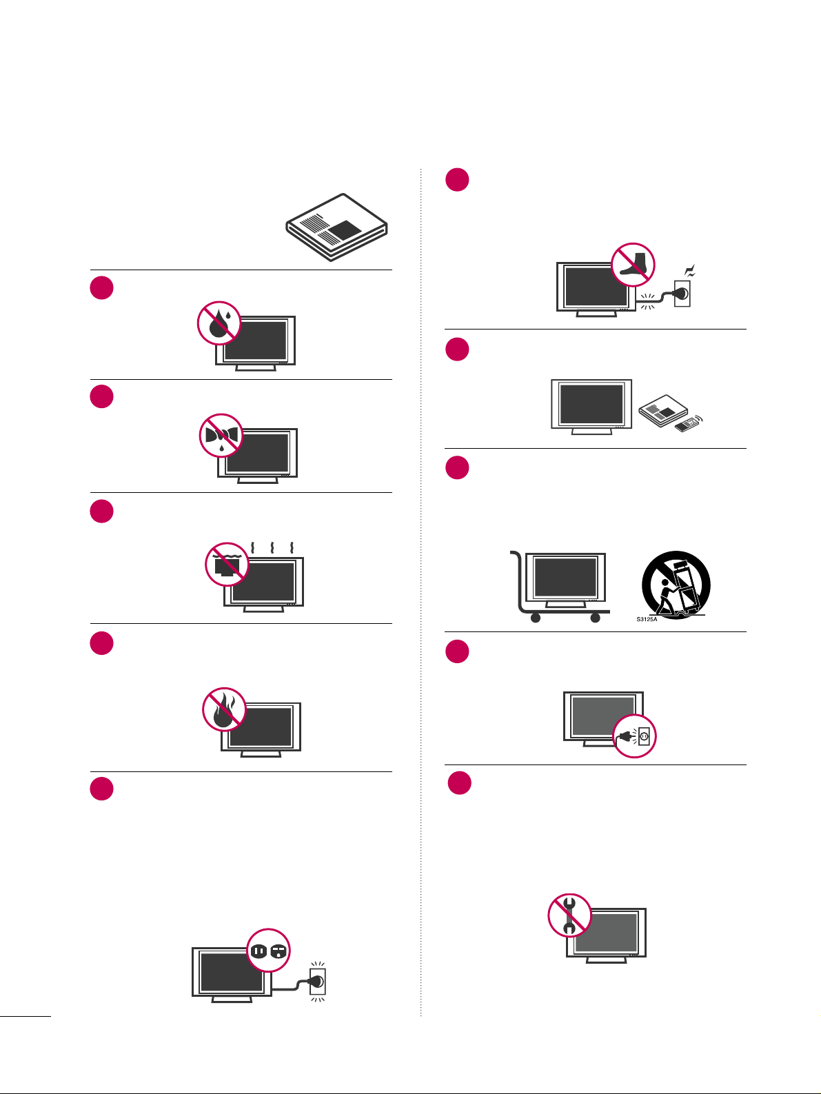
Do not use this apparatus near water.
Clean only with dry cloth.
Do not block any ventilation openings. Install in
accordance with the manufacturer’s instructions.
Do not install near any heat sources such as
radiators, heat registers, stoves, or other apparatus
(including amplifiers)that produce heat.
Do not defeat the safety purpose of the polarized
or grounding-type plug. A polarized plug has
two blades with one wider than the other. A
grounding type plug has two blades and a third
grounding prong, The wide blade or the third
prong are provided for your safety. If the provided
plug does not fit into your outlet, consult an
electrician for replacement of the obsolete outlet.
Protect the power cord from being walked on
or pinched particularly at plugs, convenience
receptacles, and the point where they exit from
the apparatus.
Only use attachments/accessories specified by
the manufacturer.
Use only with the cart, stand, tripod, bracket,
or table specified by the manufacturer, or sold
with the apparatus. When a cart is used, use
caution when moving the cart/apparatus
combination to avoid injury from tip-over.
Unplug this apparatus during lighting storms or
when unused for long periods of time.
Refer all servicing to qualified service personnel.
Servicing is required when the apparatus has been
damaged in any way, such as power-supply cord or
plug is damaged, liquid has been spilled or objects
have fallen into the apparatus, the apparatus has
been exposed to rain or moisture, does not operate
normally, or has been dropped.
2
IMPORTANT SAFETY INSTRUCTIONS
SAFETY INSTRUCTIONS
1
2
3
4
5
7
8
6
9
10
Page 5
3
Never touch this apparatus or antenna during a
thunder or lighting storm.
When mounting a TV on the wall, make sure not to
install the TV by the hanging power and signal
cables on the back of the TV.
Do not allow an impact shock or any objects to fall
into the product, and do not drop onto the screen
with something.
CAUTION concerning the Power Cord :
It is recommend that appliances be placed upon a
dedicated circuit; that is, a single outlet circuit which
powers only that appliance and has no additional
outlets or branch circuits. Check the specification
page of this owner's manual to be certain.
Do not connect too many appliances to the same
AC power outlet as this could result in fire or electric shock.
Do not overload wall outlets. Overloaded wall outlets, loose or damaged wall outlets, extension cords,
frayed power cords, or damaged or cracked wire
insulation are dangerous. Any of these conditions
could result in electric shock or fire. Periodically
examine the cord of your appliance, and if its
appearance indicates damage or deterioration,
unplug it, discontinue use of the appliance, and
have the cord replaced with an exact replacement
part by an authorized servicer. Protect the power
cord from physical or mechanical abuse, such as
being twisted, kinked, pinched, closed in a door, or
walked upon. Pay particular attention to plugs, wall
outlets, and the point where the cord exits the
appliance.
Do not make the TV with the power cord plugged
in. Do not use a damaged or loose power cord. Be
sure do grasp the plug when unplugging the power
cord. Do not pull on the power cord to unplug the
TV.
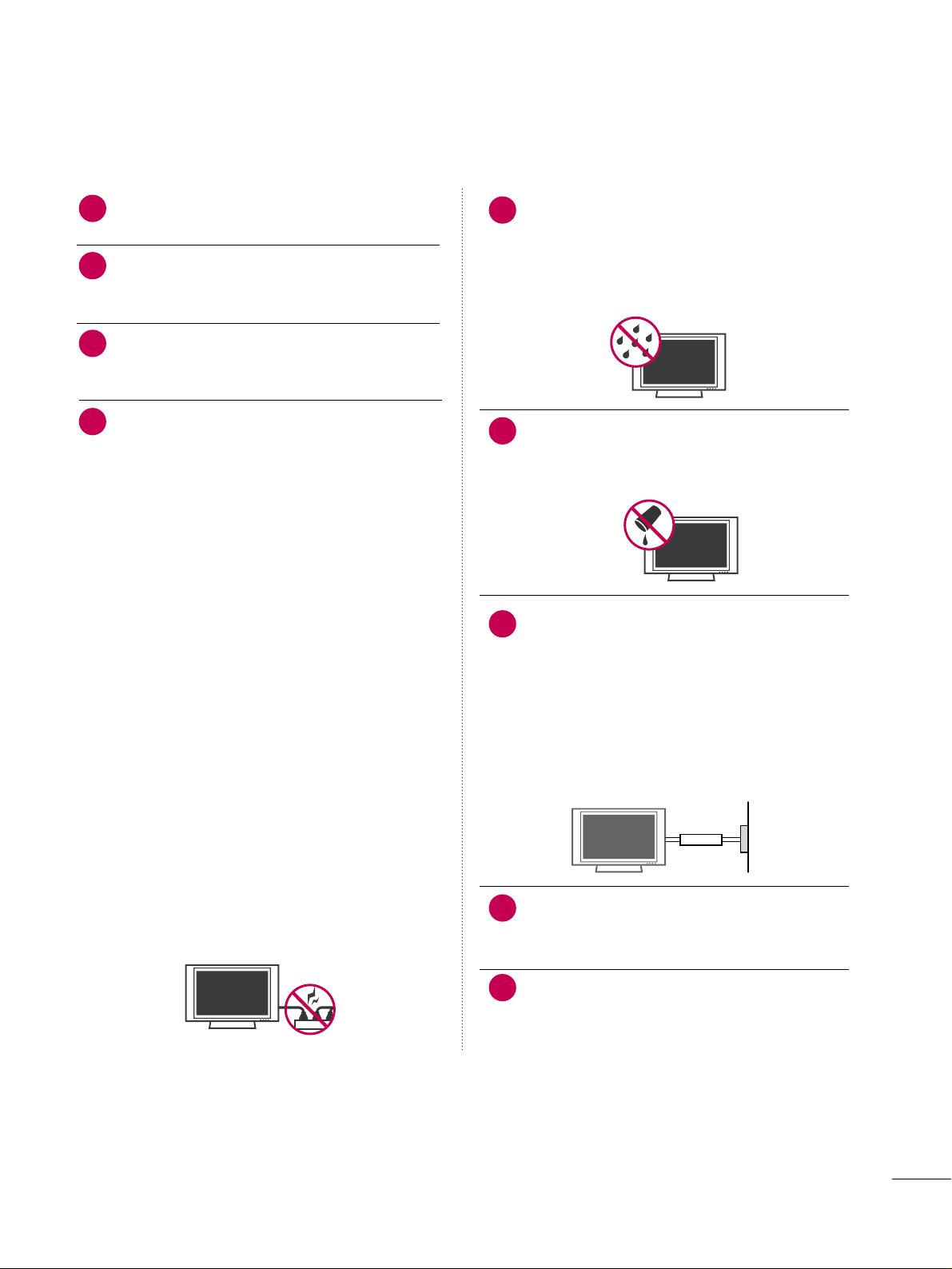
WARNING - To reduce the risk of fire or electrical
shock, do not expose this product to rain, moisture
or other liquids. Do not touch the TV with wet
hands. Do not install this product near flammable
objects such as gasoline or candles or expose the
TV to direct air conditioning.
Do not expose to dripping or splashing and do not
place objects filled with liquids, such as vases, cups,
etc. on or over the apparatus (e.g. on shelves above
the unit).
GGRROOUUNNDDIINNGG
Ensure that you connect the earth ground wire to
prevent possible electric shock. (i.e. a TV with a
three-prong grounded AC plug must be connected
to a three-prong grouned AC outlet) If grounding
methods are not possible, have a qualified electrician install a separate circuit breaker.
Do not try to ground the unit by connecting it to
telephone wires, lightening rods, or gas pipes.
DDIISSCCOONNNNEECCTTIINNGG DDEEVVIICCEE FFRROOMM MMAAIINNSS
Mains plug is the disconnecting device. The plug
must remain readily operable.
Keep the product away from direct sunlight.
12
11
14
13
16
17
18
19
Power
Supply
Short-circuit
Breaker
15
Page 6
4
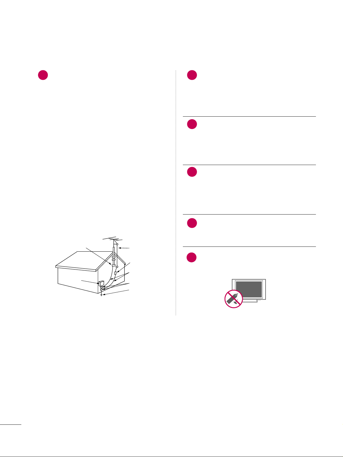
AANNTTEENNNNAASS
OOuuttddoooorr aanntteennnnaa ggrroouunnddiinngg
If an outdoor antenna is installed, follow the precautions below. An outdoor antenna system should not
be located in the vicinity of overhead power lines or
other electric light or power circuits, or where it can
come in contact with such power lines or circuits as
death or serious injury can occur.
Be sure the antenna system is grounded so as to provide some protection against voltage surges and
built-up static charges.
Section 810 of the National Electrical Code (NEC) in
the U.S.A. provides information with respect to proper grounding of the mast and supporting structure,
grounding of the lead-in wire to an antenna discharge unit, size of grounding conductors, location of
antenna discharge unit, connection to grounding
electrodes and requirements for the grounding electrode.
AAnntteennnnaa ggrroouunnddiinngg aaccccoorrddiinngg ttoo tthhee
NNaattiioonnaall EElleeccttrriiccaall CCooddee,, AANNSSII//NNFFPPAA 7700
Cleaning
When cleaning, unplug the power cord and scrub
gently with a soft cloth to prevent scratching. Do not
spray water or other liquids directly on the TV as
electric shock may occur. Do not clean with chemicals such as alcohol, thinners or benzene.
Moving
Make sure the product is turned off, unplugged
and all cables have been removed. It may take 2 or
more people to carry larger TVs. Do not press
against or put stress on the front panel of the TV.
Ventilation
Install your TV where there is proper ventilation. Do
not install in a confined space such as a bookcase.
Do not cover the product with cloth or other materials (e.g.) plastic while plugged in. Do not install in
excessively dusty places.
If you smell smoke or other odors coming from the
TV or hear strange sounds, unplug the power cord
contact an authorized service center.
Do not press strongly upon the panel with a hand or
sharp object such as nail, pencil or pen, or make a
scratch on it.
22
20
Antenna Lead in Wire
Antenna Discharge Unit
(NEC Section 810-20)
Grounding Conductors
(NEC Section 810-21)
Ground Clamps
Power Service Grounding
Electrode System (NEC
Art 250, Part H)
Ground Clamp
Electric Service
Equipment
NEC: National Electrical Code
23
24
21
25
Page 7

5
CONTENTS
WARNING / CAUTION
. . . . . . . . . . . . . . . . . . . . . . . . . . . . 1
SAFETY INSTRUCTIONS
. . . . . . . . . . . . . . . . . . . . . . . . . .
2
FEATURES OF THIS TV
. . . . . . . . . . . . . . . . . . . . . . . . . . . . . 7
PREPARATION
Accessories
. . . . . . . . . . . . . . . . . . . . . . . . . . . . . . . . . . . . . . . . . . . . . . . . . . . . . . 8
Front Panel Information
. . . . . . . . . . . . . . . . . . . . . . . . . . . . . . . . . . . . . 9
Back Panel Information
. . . . . . . . . . . . . . . . . . . . . . . . . . . . . . . . . . . . 10
Stand Instruction
. . . . . . . . . . . . . . . . . . . . . . . . . . . . . . . . . . . . . . . . . . . . .12
Cable Management
. . . . . . . . . . . . . . . . . . . . . . . . . . . . . . . . . . . . . . . . .13
Desktop Pedestal Installation
. . . . . . . . . . . . . . . . . . . . . . . . . . . . 14
Swivel Stand
. . . . . . . . . . . . . . . . . . . . . . . . . . . . . . . . . . . . . . . . . . . . . . . . . . . . 14
Attaching the TV to a desk
. . . . . . . . . . . . . . . . . . . . . . . . . . . . . . . 15
VESA Wall Mounting
. . . . . . . . . . . . . . . . . . . . . . . . . . . . . . . . . . . . . . . . 16
VESA Standard TV Mounts
. . . . . . . . . . . . . . . . . . . . . . . . . . . . . . . 17
Securing the TV to the wall to prevent falling
When the TV is used on a stand
. . . . . . . . . . . . . . . . . . . . . . . . . . 18
Antenna or Cable Connection
. . . . . . . . . . . . . . . . . . . . . . . . . . 19
MPI Card Slot
. . . . . . . . . . . . . . . . . . . . . . . . . . . . . . . . . . . . . . . . . . . . . . . . . 20
EXTERNAL EQUIPMENT SETUP
HD Receiver Setup
. . . . . . . . . . . . . . . . . . . . . . . . . . . . . . . . . . . . . . . . .21
DVD Setup
. . . . . . . . . . . . . . . . . . . . . . . . . . . . . . . . . . . . . . . . . . . . . . . . . . . . . 24
VCR Setup
. . . . . . . . . . . . . . . . . . . . . . . . . . . . . . . . . . . . . . . . . . . . . . . . . . . . . 26
Other A/V Source Setup
. . . . . . . . . . . . . . . . . . . . . . . . . . . . . . . . .
28
Pillow Speaker Setup
. . . . . . . . . . . . . . . . . . . . . . . . . . . . . . . . . . . . . . . 29
PC Setup
. . . . . . . . . . . . . . . . . . . . . . . . . . . . . . . . . . . . . . . . . . . . . . . . . . . . . . . . 30
WATCHING TV / CHANNEL CONTROL
Remote Control Functions
. . . . . . . . . . . . . . . . . . . . . . . . . . . . . . . 36
Installer Remote Control Functions
. . . . . . . . . . . . . . . . . . . 38
Turning On TV
. . . . . . . . . . . . . . . . . . . . . . . . . . . . . . . . . . . . . . . . . . . . . . . . 40
Channel Selection
. . . . . . . . . . . . . . . . . . . . . . . . . . . . . . . . . . . . . . . . . . . 41
Volume Adjustment
. . . . . . . . . . . . . . . . . . . . . . . . . . . . . . . . . . . . . . . . .41
On-Screen Menus Selection
. . . . . . . . . . . . . . . . . . . . . . . . . . . . . 42
Channel Setup
- Auto Scan (Auto Tuning)
. . . . . . . . . . . . . . . . . . . . . . . . . . . 43
- Add / Delete Channel (Manual Tuning)
. . . . . . 44
- Channel Editing
. . . . . . . . . . . . . . . . . . . . . . . . . . . . . . . . . . . . . . . . 45
Channel Label
. . . . . . . . . . . . . . . . . . . . . . . . . . . . . . . . . . . . . . . . . . . . . . . . . 46
Input List
. . . . . . . . . . . . . . . . . . . . . . . . . . . . . . . . . . . . . . . . . . . . . . . . . . . . . . . . 47
PICTURE CONTROL
Picture Size (Aspect Ratio) Control . . . . . . . . . . . . . . . . . . 48
Preset Picture Settings
- Picture Mode - Preset
. . . . . . . . . . . . . . . . . . . . . . . . . . . . . . . 51
- Color Tone - Preset
. . . . . . . . . . . . . . . . . . . . . . . . . . . . . . . . . . . 52
Manual Picture Adjustment
- Picture Mode - User Mode
. . . . . . . . . . . . . . . . . . . . . . . .
53
- Picture Mode - Expert Control
. . . . . . . . . . . . . . . . . . 54
Picture Improvement Settings
. . . . . . . . . . . . . . . . . . . . . . . . . . . 55
Advanced Control - Black (Darkness) Level
. . . . . . .
56
Advanced Control - Real Cinema
. . . . . . . . . . . . . . . . . . . . . .57
Picture Reset
. . . . . . . . . . . . . . . . . . . . . . . . . . . . . . . . . . . . . . . . . . . . . . . . . 58
SOUND & LANGUAGE CONTROL
Auto Volume Leveler (Auto Volume)
. . . . . . . . . . . . . . . . . 59
Clear Voice
. . . . . . . . . . . . . . . . . . . . . . . . . . . . . . . . . . . . . . . . . . . . . . . . . . . . . 60
Preset Sound Settings (Sound Mode)
. . . . . . . . . . . . . . . 61
Sound Setting Adjustment - User Mode
. . . . . . . . . . . 62
- SRS TruSurround XT
. . . . . . . . . . . . . . . . . . . . . . . . . . . . . . . . . 63
Balance
. . . . . . . . . . . . . . . . . . . . . . . . . . . . . . . . . . . . . . . . . . . . . . . . . . . . . . . . . .64
TV Speakers On/Off Setup
. . . . . . . . . . . . . . . . . . . . . . . . . . . . . . 65
Audio Reset
. . . . . . . . . . . . . . . . . . . . . . . . . . . . . . . . . . . . . . . . . . . . . . . . . . . 66
Stereo/SAP Broadcast Setup
. . . . . . . . . . . . . . . . . . . . . . . . . . . 67
Audio Language
. . . . . . . . . . . . . . . . . . . . . . . . . . . . . . . . . . . . . . . . . . . . . . 68
On-Screen Menus Language Selection
. . . . . . . . . . . . . 69
Caption Mode
- Analog Broadcasting System Captions
. . . . . . . 70
- Digital Broadcasting System Captions
. . . . . . . . 71
- Caption Option
. . . . . . . . . . . . . . . . . . . . . . . . . . . . . . . . . . . . . . . 72
TIME SETTING
Clock Setting
- Auto Clock Setup
. . . . . . . . . . . . . . . . . . . . . . . . . . . . . . . . . . . . 73
- Manual Clock Setup
. . . . . . . . . . . . . . . . . . . . . . . . . . . . . . . . . 74
Auto On/Off Time Setting
. . . . . . . . . . . . . . . . . . . . . . . . . . . . . . 75
Sleep Timer Setting
. . . . . . . . . . . . . . . . . . . . . . . . . . . . . . . . . . . . . . . . .76
Auto Shut-off Setting
. . . . . . . . . . . . . . . . . . . . . . . . . . . . . . . . . . . . . . . 77
Page 8

6
PARENTAL CONTROL / RATINGS
Set Password & Lock System . . . . . . . . . . . . . . . . . . . . . . . . . . . 78
Channel Blocking
. . . . . . . . . . . . . . . . . . . . . . . . . . . . . . . . . . . . . . . . . . . . 81
Movie & TV Rating
. . . . . . . . . . . . . . . . . . . . . . . . . . . . . . . . . . . . . . . . .82
Downloadable Rating
. . . . . . . . . . . . . . . . . . . . . . . . . . . . . . . . . . . . . . 85
External Input Blocking
. . . . . . . . . . . . . . . . . . . . . . . . . . . . . . . . . . . . 86
CHANNEL BANKS
Channel Banks Overview . . . . . . . . . . . . . . . . . . . . . . . . . . . . . . . . . . 87
Channel Banks Setup Installer Remote Control Key
Functions
. . . . . . . . . . . . . . . . . . . . . . . . . . . . . . . . . . . . . . . . . . . . . . . . . . . . . . . .88
Channel Banks Setup
. . . . . . . . . . . . . . . . . . . . . . . . . . . . . . . . . . . . . . 89
Reference: Channel Banks Worksheet
. . . . . . . . . . . . . . . 90
COMMERCIAL MODE SETUP
Installer Overview
. . . . . . . . . . . . . . . . . . . . . . . . . . . . . . . . . . . . . . . . . . . . 91
TV overview
. . . . . . . . . . . . . . . . . . . . . . . . . . . . . . . . . . . . . . . . . . . . . . . . . . . .
92
Commercial Mode Setup for Master TV
. . . . . . . . . . . . 93
Master TV Profile Setup Learning/Teaching with
USB Memory Card
. . . . . . . . . . . . . . . . . . . . . . . . . . . . . . . . . . . . . . . . . . 94
TLL-1100A Clone Connections / Learning and
Teaching Setups
. . . . . . . . . . . . . . . . . . . . . . . . . . . . . . . . . . . . . . . . . . . . . .96
LT2002 Cloning Connections/Learning Setup
. . 97
Cloning Learning Setup
. . . . . . . . . . . . . . . . . . . . . . . . . . . . . . . . . . . 98
Cloning Connections/Teaching Setup
. . . . . . . . . . . . .99
Installer Menu
. . . . . . . . . . . . . . . . . . . . . . . . . . . . . . . . . . . . . . . . . . . . . . . .10 0
Reference: Detailed Information For Making A
Master TV
. . . . . . . . . . . . . . . . . . . . . . . . . . . . . . . . . . . . . . . . . . . . . . . . . . . . .10 7
Reference: Procedures for adding Channel Label
Icons/Custom Channel Labels (2-5-4 + MENU
Mode)
. . . . . . . . . . . . . . . . . . . . . . . . . . . . . . . . . . . . . . . . . . . . . . . . . . . . . . . . . . .10 8
Reference: Clonable Menu Features
. . . . . . . . . . . . . . . . .10 9
Reference: Checking Software Version
. . . . . . . . . . . . .109
TV Aux Input Configuration
. . . . . . . . . . . . . . . . . . . . . . . . . . . . .110
Power Saving Setup
. . . . . . . . . . . . . . . . . . . . . . . . . . . . . . . . . . . . . . . . .110
APPENDIX
Troubleshooting . . . . . . . . . . . . . . . . . . . . . . . . . . . . . . . . . . . . . . . . . . . . . .111
Reference: LT2002 Cloning Procedure
Troubleshooting
. . . . . . . . . . . . . . . . . . . . . . . . . . . . . . . . . . . . . . . . . . . . . .113
Channel Banks Setup Troubleshooting
. . . . . . . . . . . . .114
Troubleshooting Flow Chart
. . . . . . . . . . . . . . . . . . . . . . . . . . . .115
Commercial Mode Check
. . . . . . . . . . . . . . . . . . . . . . . . . . . . . . . .116
Glossary of Terms
. . . . . . . . . . . . . . . . . . . . . . . . . . . . . . . . . . . . . . . . . . .
117
Maintenance
. . . . . . . . . . . . . . . . . . . . . . . . . . . . . . . . . . . . . . . . . . . . . . . . . . .118
Product Specifications
. . . . . . . . . . . . . . . . . . . . . . . . . . . . . . . . . . . .119
IR Codes
. . . . . . . . . . . . . . . . . . . . . . . . . . . . . . . . . . . . . . . . . . . . . . . . . . . . . . .
12 0
Page 9
7
is a trademark of SRS Labs, Inc.
TruSurround XT technology is incorporated under
license from SRS Labs, Inc.
Manufactured under license from Dolby Laboratories.
“
Dolby
“and the double-D symbol are trademarks of
Dolby Laboratories.
FEATURES OF THIS TV
USB IN
SERVUCE ONLYSERVUCE ONLY
USB port shall be used for software update by service
personnel only.
FOR LCD TV
■
If the TV feels cold to the touch, there may be a small “flicker” when it is turned on. This is normal, there is nothing wrong
with TV.
■
Some minute dot defects may be visible on the screen, appearing as tiny red, green, or blue spots. However, they have no adverse
effect on the monitor's performance.
■
Avoid touching the LCD screen or holding your finger(s) against it for long periods of time. Doing so may produce some
temporary distortion effects on the screen.
On Disposal
The fluorescent lamp used in this product contains a small amount of mercury. Do not dispose of this product with general
household waste. Disposal of this product must be carried out in accordance to the regulations of your local authority.
HDMITM, the HDMI logo and High-Definition
Multimedia Interface are trademarks or registered
trademarks of HDMI Licensing."
Page 10
PREPARATION
8
PREPARATION
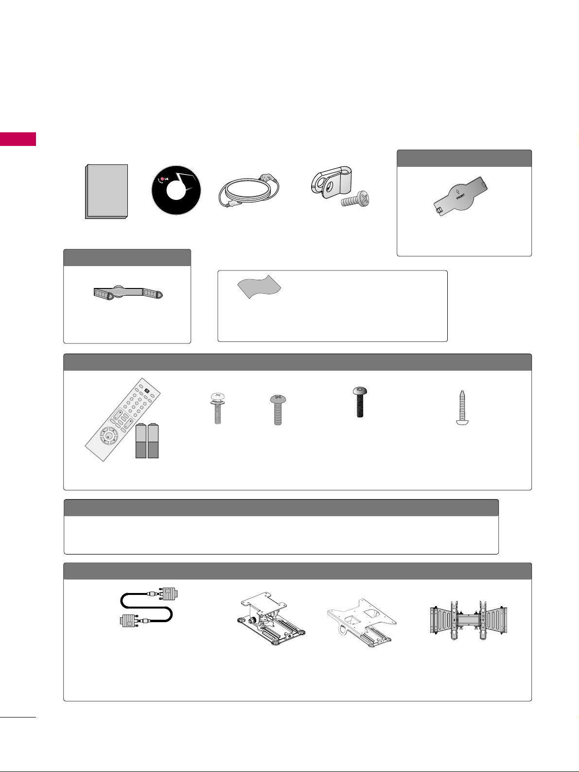
ACCESSORIES
Ensure that the following accessories are included with your TV. If an accessory is missing, please contact the
dealer where you purchased the TV.
The accessories included may differ from the images below.
OOppttiioonn EExxttrraass
D-sub 15 pin Cable
When using the VGA (D-sub 15 pin cable) PC
connection, the user must use shielded signal
interface cables with ferrite cores to maintain
standards compliance.
OOppttiioonnaall IInnssttaalllleerr RReemmoottee CCoonnttrrooll ffoorr MMooddeell NNoo.. SSeerriieess 2222//2266//3322LLGG33DDCCHH
There is an optional Installer remote control available for the 22/26/32LG3DCH models. The
installer remote control is NOT included with the TV.
Tilt Wall Mounting Bracket
(AW-47LG30M)
(Only 32LG3DCH)
Wall Mounting Bracket
(RW230)
(Only 26LG3DCH)
3322LLGG33DDCC oonnllyy
1.5V 1.5V
Remote Control,
Batteries
123
456
78
0-
9
VOL CH
ENTER
POWER
MUTE
MENU
A
D
JU
S
T
R
ETU
R
N
CC
SAP
FLASHBK
PICTURE
S
O
U
N
D
RATIO
TV
IN
P
U
T
TIMER
Bolts for stand assembly
(Refer to P.12)
Screw for stand fixing
(Refer to P.15)
x 4 x 4
x 2
Torx plus
Star head screw
(Refer to P.12)
M4xL26
(Machine Screw)
Ø
4xL20
(Plastic Screw)
Ø
4xL20
(Plastic Screw)
M4xL22
(Machine Screw)
Wall Mounting Bracket
(RW120)
(Only 22LG3DCH)
2222LLGG33DDCCHH oonnllyy
Copyright© 2007 LGE,
All Rights Reserved.
Owner’s Manual
Power Cord
CD Manual
Cable Management Clip
(Refer to P.13)
2266//3322LLGG33DDCCHH,, 3322LLGG33DDCC oonnllyy
Protection Cover
(Refer to P.12)
Protective Bracket and
Bolt for Power Cord
(Refer to P.13)
(This feature is not available for
all models.)
* Wipe spots on the exterior only with the pol-
ishing cloth.
* Do not wipe roughly when removing stains.
Excessive pressure may cause scratches or
discoloration.
Polishing Cloth
(This feature is not avail-
able for all models.)
Page 11
PREPARATION
9
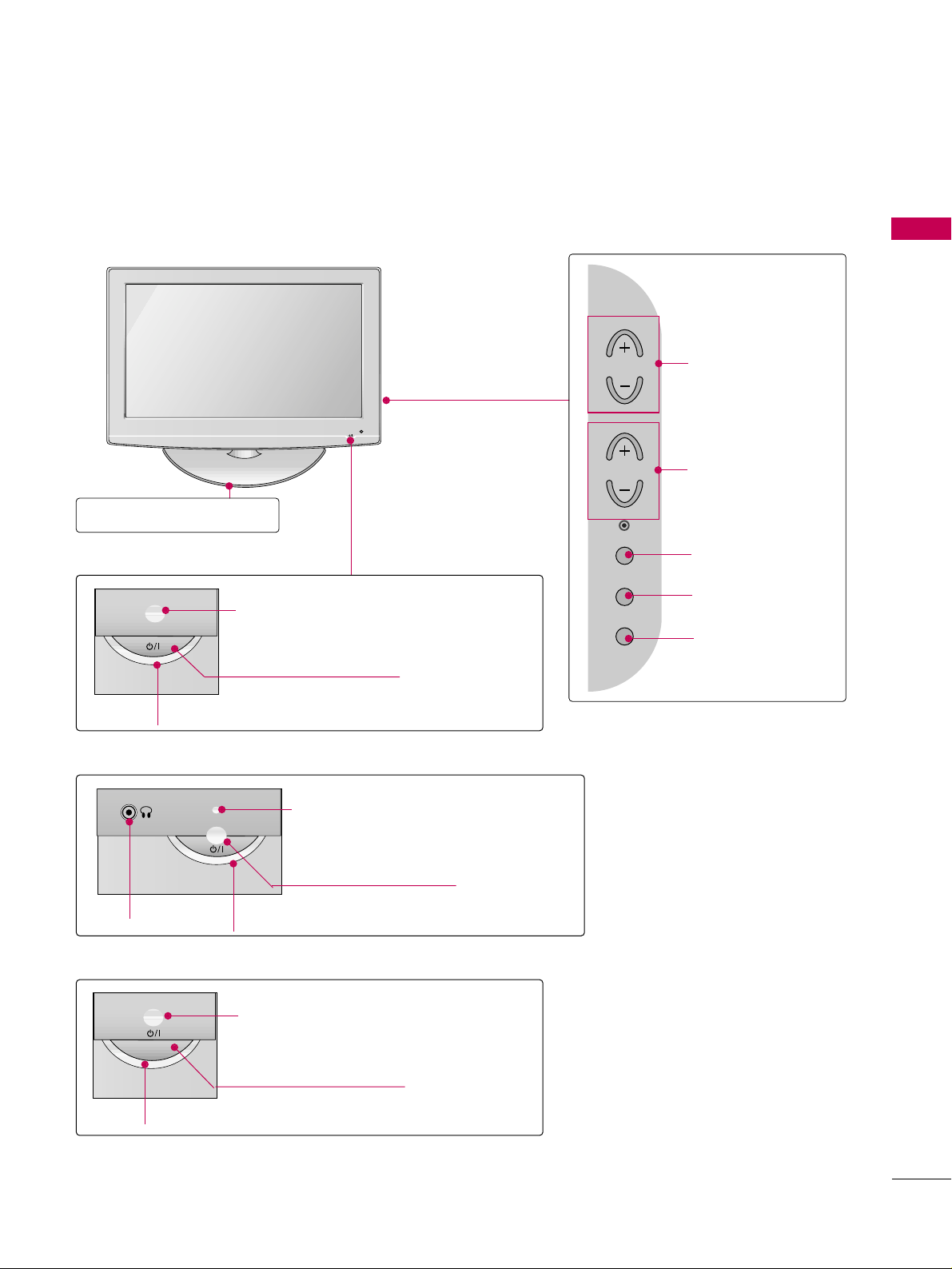
FRONT PANEL INFORMATION
■
Image shown may differ from your TV.
■
NOTE: If your TV has a protection tape attached, remove the tape.
And then wipe the TV with a cloth (If a polishing cloth is included with your TV, use it).
POWER Button
Power/Standby Indicator
Illuminates red in standby mode.
Illuminates blue when the set is switched on.
VOLUME (+, -)
Buttons
ENTER Button
MENU Button
INPUT Button
Remote Control Sensor
CHANNEL(+, -)
Buttons
POWER Button
Power/Standby Indicator
Illuminates red in standby mode.
Illuminates green when the set is switched
on.
Remote Control Sensor
Stand
26/32LG3DCH model
32LG3DC model
(only 32LG3DC)
22LG3DCH model
POWER Button
Power/Standby Indicator
Illuminates red in standby mode.
Illuminates green when the set is
switched on.
Remote Control Sensor
Headphone
CH
VOL
ENTER
MENU
INPUT
Page 12
PREPARATION
10
PREPARATION
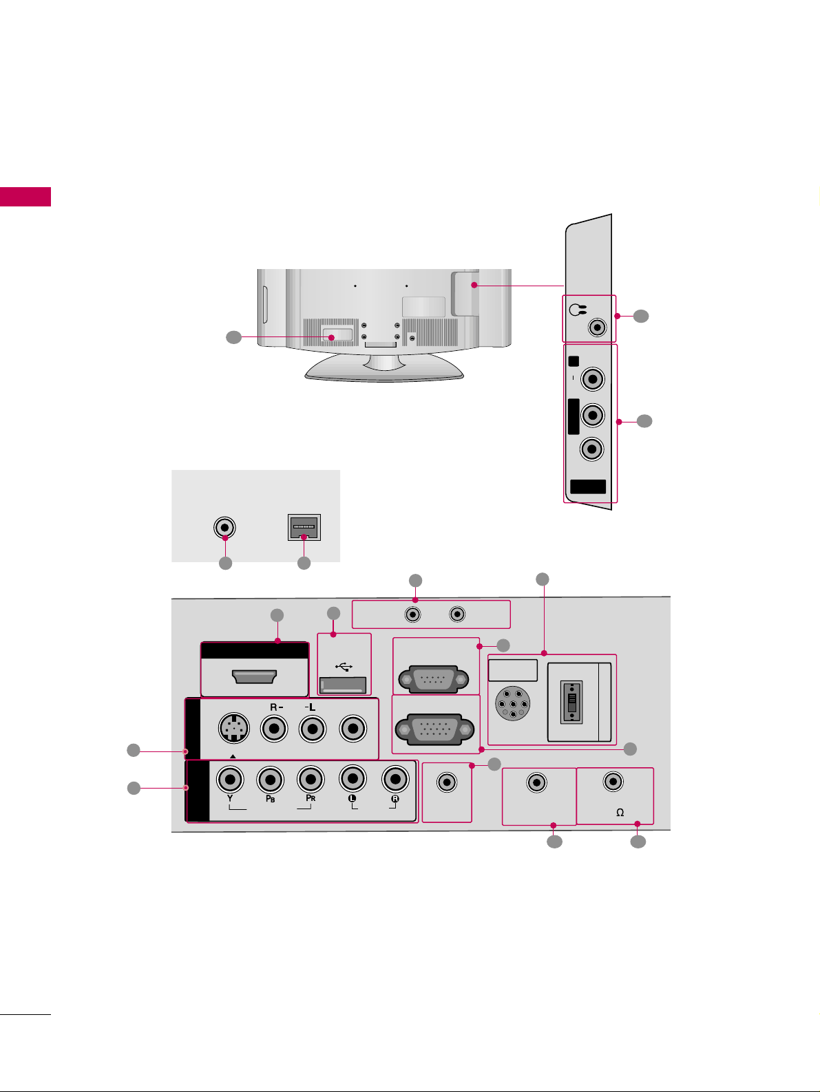
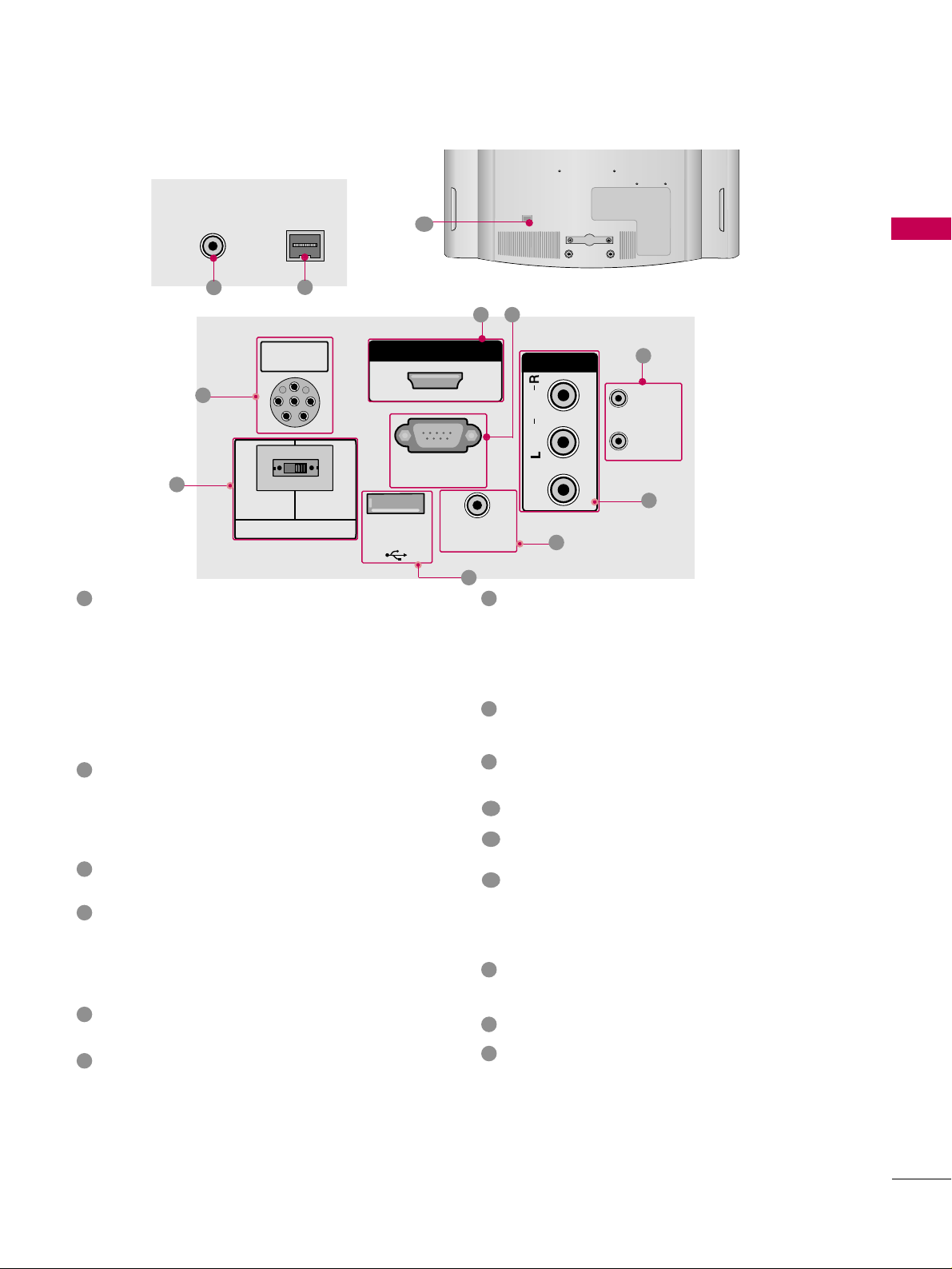
BACK PANEL INFORMATION
■
Image shown may differ from your TV.
R
1
11
AV IN 2
L/ MONO
R
AUDIO
VIDEO
H/P
12
AUDIO IN
(RGB/DVI)
VIDEO
AUDIOAUDIO
HDMI/DVI INHDMI/DVI IN
USB INUSB IN
SERVUCE ONLYSERVUCE ONLY
AV IN 1
VIDEOVIDEO
MONO
( )
AUDIOAUDIO
S-VIDEO
COMPONENTCOMPONENT
IN
RGB IN (PC)
RESET
UPDATE
RS-232C INRS-232C IN
(SERVICE ONLY)(SERVICE ONLY)
REMOTE
CONTROL OUT
SPEAKER OUT
8
R
PILLOW
SPEAKER
NORMALNORMAL
SPEAKERSPEAKER
PILLOWPILLOW
SPEAKERSPEAKER
SPEAKER SWITCH
PILLOW
SPEAKER
NORMAL
SPEAKER
PILLOW
SPEAKER
SPEAKER SWITCH
6
5
1
8
2
3
4
9 10
15
(only 26/32LG3DCH model)
For 32LG3DC
26/32LG3DCH
R
ANTENNA INANTENNA IN
M.P.I.M.P.I.
7
13
14
Page 13
PREPARATION
11
For 22LG3DCH
R
ANTENNA INANTENNA IN
M.P.I.M.P.I.
13
14
12
R
PILLOW
SPEAKER
NORMAL
SPEAKER
PILLOW
SPEAKER
SPEAKER SWITCH
PILLOWPILLOW
SPEAKERSPEAKER
HDMI/DVI INHDMI/DVI IN
RS-232C INRS-232C IN
(SERVICE ONLY)(SERVICE ONLY)
USB INUSB IN
SERVUCE ONLYSERVUCE ONLY
REMOTEREMOTE
CONTROL OUTCONTROL OUT
AV IN AV IN
VIDEOVIDEO
AUDIOAUDIO
MONOMONO
( )
NORMALNORMAL
SPEAKERSPEAKER
PILLOWPILLOW
SPEAKERSPEAKER
SPEAKER SWITCHSPEAKER SWITCH
RESETRESET
UPDATEUPDATE
RS-232C IN
(SERVICE ONLY)
USB IN
SERVUCE ONLY
REMOTE
CONTROL OUT
AV IN
VIDEO
AUDIO
MONO
( )
RESET
UPDATE
DVI AUDIO IN
DVI AUDIO INDVI AUDIO IN
15
15
2
5
1
3
4
9
COMPONENT IN (Except 22LG3DCH model)
Analog Connection.
Supports HD.
Uses a red, green, and blue cable for video & a red
and white cable for audio.
AUDIO IN (RGB/DVI)
(Except 22LG3DCH model)
1/8” headphone jack for analog PC audio input.
REMOTE CONTROL OUT
IR output for controlling an auxiliary device.
SPEAKER OUT 8
Ω (Except 22LG3DCH model)
H/P
Plug the headphone into the headphone socket.
Power Cord Socket
For operation with AC power.
Caution: Never attempt to operate the TV on DC
power.
ANTENNA IN
Connect over-the air signals to this jack.
M.P. I.
PILLOW SPEAKER (Except 32LG3DC model)
Used to connect to pillow speaker.
SPEAKER SWITCH (Except 32LG3DC model)
Used to select the speaker output switch.
Note: If Pillow Speaker is selected, no Sound will be
heard from TV speakers.
(NORMAL SPEAKER or PILLOW SPEAKER)
AV (Audio/Video) IN
Analog composite connection. Supports standard
definition video only (480i).
Used for PC/DTV audio input jack (Only 22LG3DCHUA model).
S-VIDEO (Except 22LG3DCH model)
Better quality than standard composite (yellow
RCA cable). Supports standard definition video
only (480i).
HDMI/DVI IN
Digital Connection. Supports HD video and Digital
audio.
Accepts DVI video using an adapter or HDMI to
DVI cable (not included).
USB IN SERVICE ONLY
Used for software updates.
UPDATE
Software downloads and debug mode enable/disable.
RESET
Hardware reset to PTC microcontroller.
RS-232C IN (SERVICE ONLY)
Used for software updates.
RGB IN (PC) (Except 22LG3DCH model)
Analog PC Connection. Uses a D-sub 15 pin cable
(VGA cable).
1
2
3
4
5
9
8
6
10
11
12
13
14
15
7
Page 14
PREPARATION
12
PREPARATION
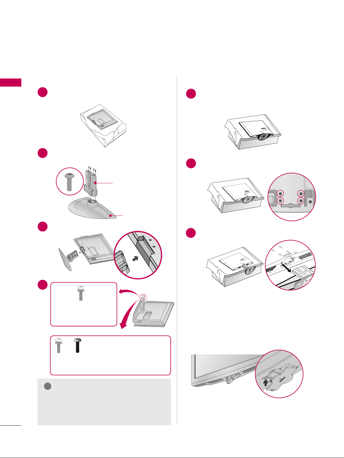
STAND INSTRUCTION
Carefully place the TV screen side down on a
cushioned surface to protect the screen from
damage.
Assemble the parts of the
SSTTAANN DD BBOO DDYY
with
CC OOVVEE RR BBAASS EE
of the TV.
1
2
Insert the stand as shown.
3
SSTTAA NNDD BBOODD YY
CC OOVVEE RR BBAASS EE
■
Image shown may differ from your TV.
GG
Make sure the screws in the stand are fully
tightened. (If not tightened fully, the product
could tilt forward and fall). But do not over
tighten, over-tightening can damage the threads
on the screws.
NOTE
!
DETACHMENT
(Only 32LG3DC)
Carefully place the TV screen side down on a
cushioned surface to protect the screen from
damage.
1
Remove the four screws that hold the base on.
2
Detach the stand from TV.
3
After removing the stand, install the included
pp rrootteecctt iioonn ccoovv ee rr
over the hole for the stand.
Press the
PPRROO TTEECCTT II OONN CCOOVVEERR
into the TV
until you hear it click.
PROTECTION COVER
(Except 22LG3DCH)
INSTALLATION
(Only 32LG3DC)
4
or
x 4
Tighten the stand with the
four screws (provided as parts
of the TV).
Tighten the two of these four screws
and the two Torx plus star head screws
(provided as parts of the TV) to secure the TV. Tighten
the two Torx plus star head screws with a star head driver bit (not provided as parts of the TV).
x 2
x 2
Page 15
PREPARATION
13
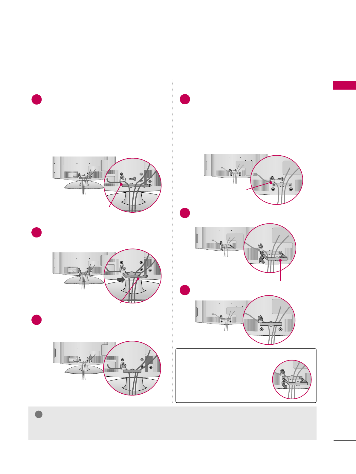
CABLE MANAGEMENT
Install the CABLE MANAGEMENT CLIP as
shown.
2
■
Image shown may differ from your TV.
Connect the cables as necessary.
To connect additional equipment, see the
EXTERNAL EQUIPMENT SETUP section.
Secure the power cable with the
PROTECTIVE BRACKET and the screw as
shown. It will help prevent the power cable
from being removed by accident.
Install the CABLE MANAGEMENT CLIP as
shown.
CABLE MANAGEMENT CLIP
1
2
Put the cables inside the CABLE MANAGEMENT
CLIP and snap it closed.
3
PROTECTIVE BRACKET
(This feature is not available
for all models.)
Connect the cables as necessary.
To connect additional equipment, see the
EXTERNAL EQUIPMENT SETUP section.
Secure the power cable with the
PROTECTIVE BRACKET and the screw as
shown. It will help prevent the power cable
from being removed by accident.
CABLE MANAGEMENT CLIP
1
Fit the CABLE MANAGEMENT CLIP as shown.
3
GG
Do not hold the CABLE MANAGEMENT CLIP when moving the TV.
- If the TV is dropped, you may be injured or the product may be broken.
NOTE
!
How to remove the
CABLE MANAGEMENT CLIP
GG
Hold the CABLE MANAGEMENT CLIP with both hands
and pull it backward.
For 22LG3DCH For 26/32LG3DCH, 32LG3DC
PROTECTIVE BRACKET
(This feature is not available
for all models.)
Page 16
PREPARATION
14
PREPARATION
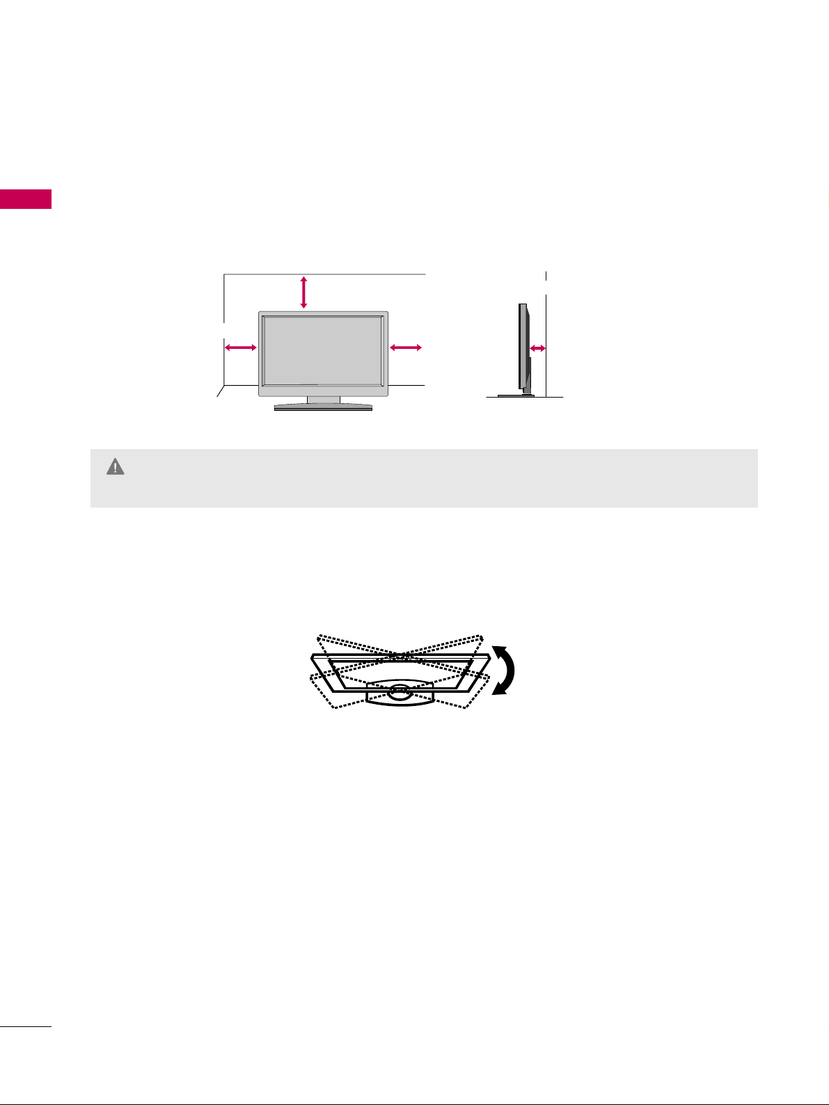
DESKTOP PEDESTAL INSTALLATION
For proper ventilation, allow a clearance of 4 inches on all four sides.
■
Image shown may differ from your TV.
* This feature is not available for all models.
4 inches
4 inches
4 inches
4 inches
SWIVEL STAND (Only 32LG3DC)
The TV can be conveniently swivelled on its stand 90° to the left or right to provide the optimum viewing angle.
GG
Ensure adequate ventilation by following the clearance recommendations.
GG
Do not mount near or above any type of heat source.
CAUTION
Page 17
PREPARATION
15
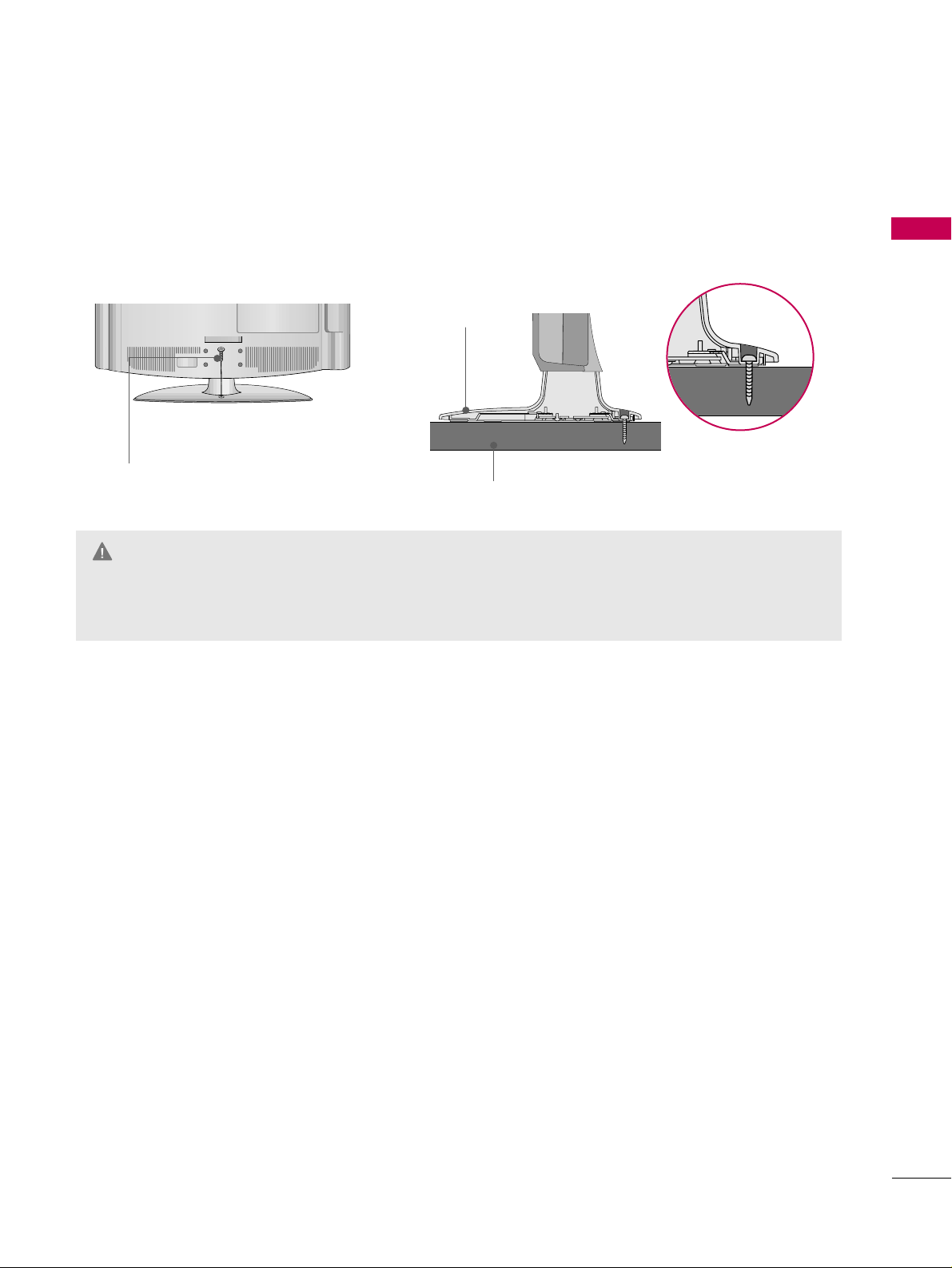
ATTACHING THE TV TO A DESK (Only 32LG3DC)
The TV must be attached to a desk so it cannot be pulled in a forward/backward direction, potentially causing
injury or damaging the product. Use only the included screw.
GG
To prevent TV from falling over, the TV should be securely attached to the floor/wall per installation
instructions. Tipping, shaking, or rocking the TV may cause injury.
WARNING
1-Screw
(provided as parts of the product)
Desk
Stand
Page 18
PREPARATION
16
PREPARATION
VESA WALL MOUNTING
Install your wall mount on a solid wall perpendicular to the floor. When attaching to other building materials, please contact your nearest dealer.
If installed on a ceiling or slanted wall, it may fall and result in severe personal injury.
We recommend that you use an LG brand wall mount when mounting the TV to a wall.
GG
Do not install your wall mount kit while the TV is plugged in. It may result in personal injury due to electric
shock.
CAUTION
GG
Screw length needed depends on the wall mount
used. For further information, refer to the instructions included with the mount.
GG
Standard dimensions for wall mount kits are shown
in the table.
GG
When purchasing our wall mount kit, a detailed
installation manual and all parts necessary for
assembly are provided.
GG
Do not use screws longer then the standard dimension, as they may cause damage to the inside to
the TV.
GG
For wall mounts that do not comply with the VESA
standard screw specifications, the length of the
screws may differ depending on their specifications.
GG
Do not use screws that do not comply with the
VESA standard screw specifications.
Do not tighten the screws too much. It may damage the TV or allow the TV to a fall and cause personal injury. LG is not liable for these kinds of accidents.
GG
LG is not liable for TV damage or personal injury
when a non-VESA or non specified wall mount is
used or the consumer fails to follow the TV installation instructions.
NOTE
!
Product Model
VESA
(A *B)
Standard Screw Quantity
26LG3DCH, 32LG3DCH
32LG3DC
200* 10 0
M4 4
LCD TV
AA
BB
GG
To prevent injury, this apparatus must be securely attached to the wall in accordance with the installation instructions.
WARNING
22LG3DCH 100* 10 0
M4
4
Page 19
PREPARATION
17
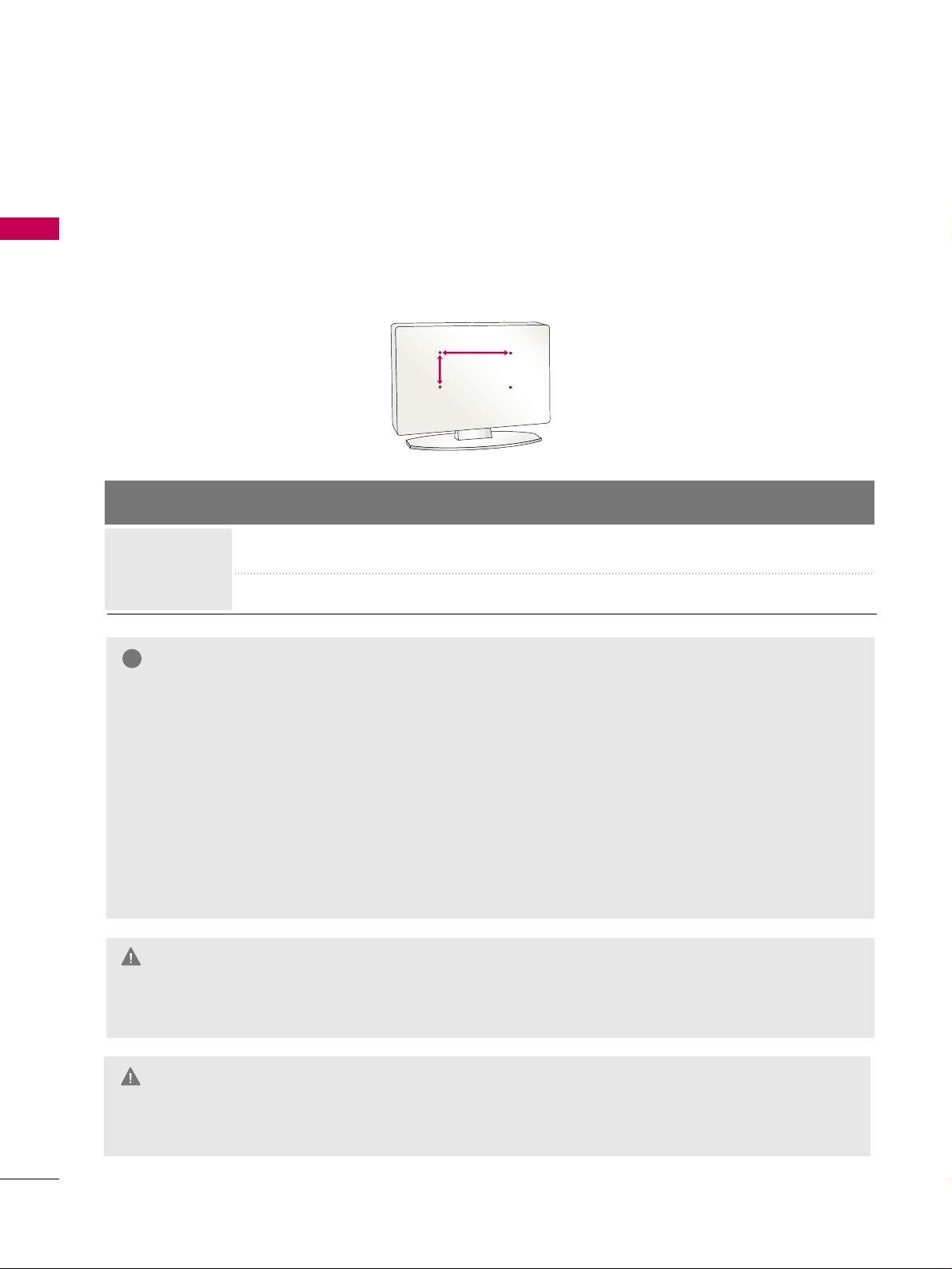
General Guidelines: Choosing a
Location for installing a VESA
Standard
MMoo uu nntt
To the right are some examples of VESA standard
mounts. Since there are numerous types of stands and
mounts available, only a few are shown here. Refer to the
instructions provided with the TV stand that will be
used to mount the TV. Be sure the style of stand selected is capable of supporting the weight of the TV and is
appropriate for the application.
WWaall ll MMoouu nnttss
If the mount will be on a wall, a typical wooden stud
behind the wall board would be the preferred choice for
a location to attach the wall mount. The wall mount
location chosen should be appropriate for drilling holes
and have available the required power source as well as
antenna/cable and any other equipment leads as necessary.
PPee dd ee ssttaall MMoouunn ttss aann dd SSttaanndd ss
A sturdy surface on a desk or other similar flat table-like
furniture would be the appropriate location for mounting a pedestal-style TV stand.
Most stands are designed so that the wiring is threaded
through the stand itself or a loop-through style clamp
so that the wiring is neatly bunched and not strung in
such a way as to create a potential hazard to the user.
(Some stands are portable and can be moved from one
location to another.) Be sure all safety considerations
are followed.
Typical Pedestal Type Mount with
Swivel Bracket
Typical Wall Stud Type Mount with Swivel
Bracket
VESA STANDARD TV MOUNTS
Page 20
PREPARATION
18
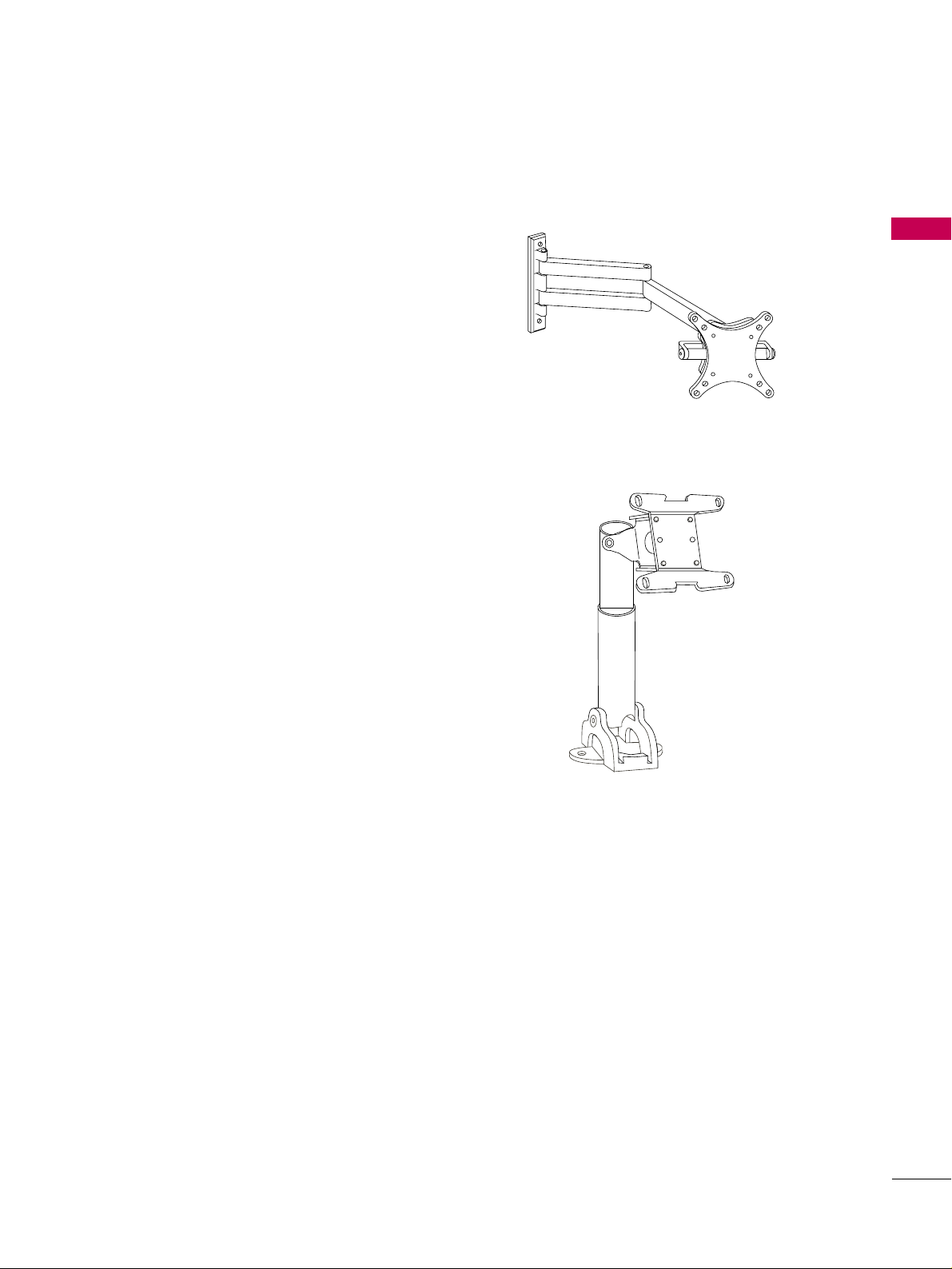
SECURING THE TV TO THE WALL TO PREVENT FALLING WHEN THE TV IS USED ON A STAND
PREPARATION
We recommend that you set the TV close to a wall so it cannot fall over if pushed backwards.
Additionally, we recommend that the TV be attached to a wall so it cannot be pulled in a forward direction,
potentially causing injury or damaging the product.
Caution: Please make sure that children don’t climb on or hang from the TV.
■
Insert eye-bolts (or TV brackets and bolts) to attach the product to the wall as shown in the picture.
*If your product has the bolts in the eye-bolts position before inserting the eye-bolts, loosen the bolts.
* Insert the eye-bolts or TV brackets/bolts and tighten them securely in the upper holes.
Secure the wall brackets with screws (sold separately) to the wall. Match the height of the bracket that
is mounted on the wall to the holes in the product.
Ensure the eye-bolts or brackets are tightened securely.
■
Use a sturdy rope or cord (sold separately) to tie the product. It is
safer to tie the rope so it becomes horizontal between the wall and
the product (the less slack in the rope, the better).
■
You should purchase necessary components to prevent TV from falling off of the stand.
■
Image shown may differ from your TV.
* This feature is not available for all models.
GG
Use a platform or cabinet strong enough and large enough to support the size and weight of the TV.
GG
To use the TV safely, make sure that the height of the bracket on the wall and the one on the TV are
the same.
NOTE
!
Page 21
PREPARATION
19
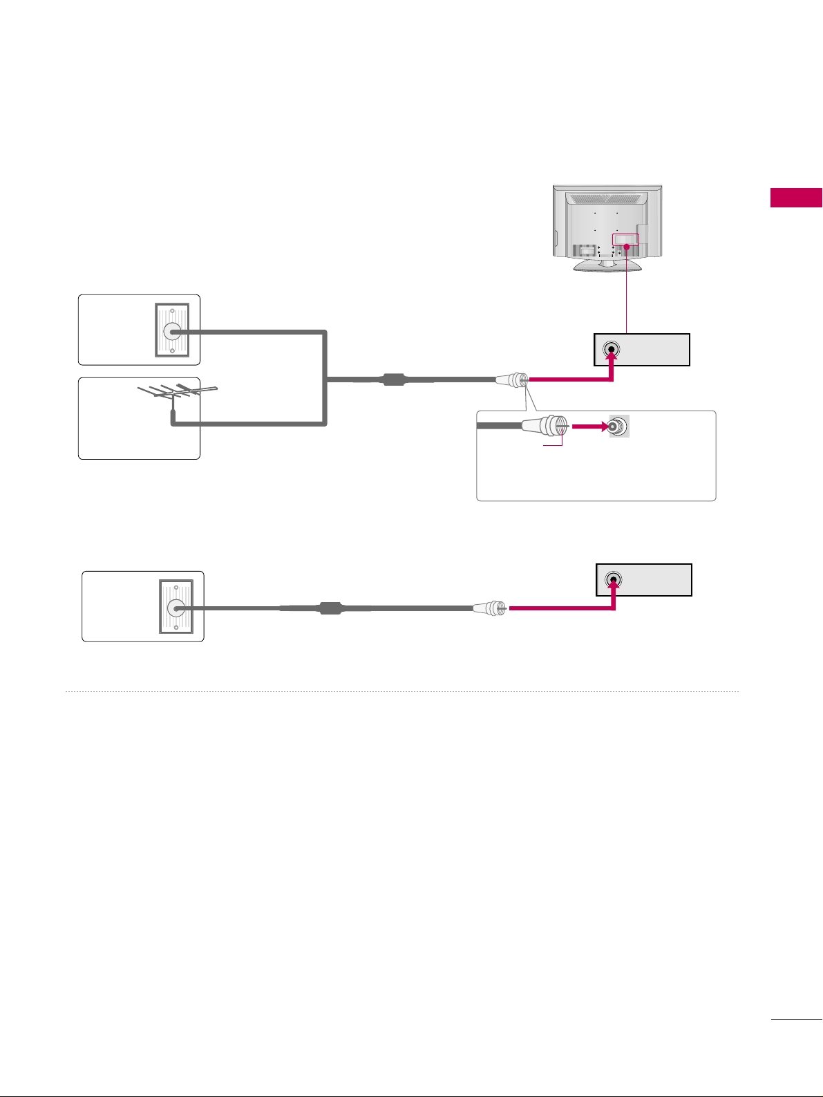
ANTENNA OR CABLE CONNECTION
■
To prevent damage do not connect to the power outlet until all connections are made between the devices.
ANTENNA IN
1. Antenna (Analog or Digital)
Wall Antenna Socket or Outdoor Antenna without a Cable Box
Connection.
For optimum picture quality, adjust the direction if needed.
2. Cable
Wall
Antenna
Socket
Outdoor
Antenna
(VHF, UHF)
Cable TV
Wall Jack
Multi-family Dwellings/Apartments
(Connect to wall antenna socket)
RF Coaxial Wire (75 ohm)
RF Coaxial Wire (75 ohm)
Single-family Dwellings /Houses
(Connect to wall jack for outdoor antenna)
Be careful not to bend the copper wire
when connecting the antenna.
Copper Wire
■
To improve the picture quality in a poor signal area, please purchase a signal amplifier and install properly.
■
If the antenna needs to be split for two TV’s, install a 2-Way Signal Splitter.
■
If the antenna is not installed properly, contact your dealer for assistance.
R
ANTENNA IN
Page 22
PREPARATION
20
PREPARATION
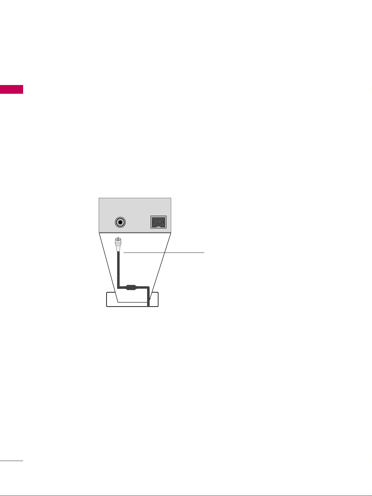
ANTENNAANTENNA IN
M.PM.P.I.
M.P. I.
Card Slot
RR FF CC AA BB LL EE
RF cable needs to be disconnected to remove current card.
1. Remove the two MPI card retainer screws.
2. Pull out current MPI card far enough so that the RF cable can be detached from the old card.
2. Detach RF cable.
3. Place new PPV card into slot and slide it in far enough to reconnect RF cable.
4. Reconnect RF cable.
5. Insert card all the way into the slot making sure it is fully seated into back plane connector.
6. Replace the two card retainer screws.
The MPI card is equipped with an RF jack for antenna/cable signal source connection.
The slot is also available for installing a PPV (Pay-Per-View) card.
MPI Card Removal / PPV Card Installation
MPI CARD SLOT
Page 23
EXTERNAL EQUIPMENT SETUP
21
EXTERNAL EQUIPMENT SETUP
■
To prevent the equipment damage, never plug in any power cords until you have finished connecting all equipment.
■
This part of EXTERNAL EQUIPMENT SETUP mainly uses the picture for 32LG3DC model.
HD RECEIVER SETUP
This TV can receive Digital Over-the-air or Digital Cable signals without an external digital set-top box. However,
if you do receive digital signals from a digital set-top box or other digital external device, refer to the figure as
shown below.
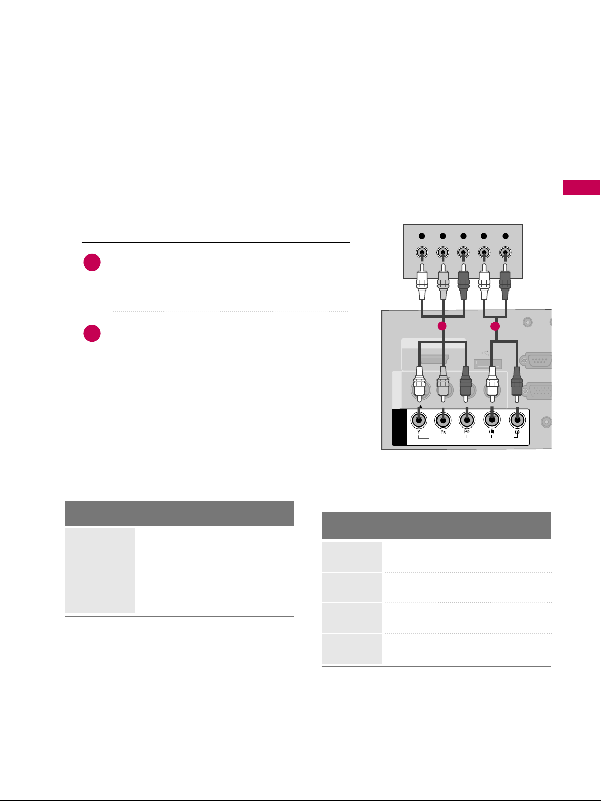
Component Connection
(Except 22LG3DCH)
1. How to connect
Connect the video outputs (Y, PB, PR
)
of the digital set-
top box to the
CC OOMMPPOO NNEENNTT II NN VV IIDDEE OO
jacks on
the TV. Match the jack colors (Y = green, P
B = blue, and
P
R = red).
Connect the audio output of the digital set-top box to
the
CC OOMMPPOO NNEENNTT IINN AAUU DDIIOO
jacks on the TV.
2
1
2. How to use
■
Turn on the digital set-top box.
(
Refer to the owner’s manual for the digital set-top box.
)
■
Select
CC oommppoonn eenn tt
input source using the
IINNPPUU TT
button
on the remote control.
( )
AUDIO
(RGB/D
AUDIO IN
(RGB/DVI)
HDMI/DVI IN
USB IN
SERVUCE ONLY
VIDEO
MONO
( )
AUDIO
S-VIDEOS-VIDEO
RGB IN (PCRGB IN (PC)
RESET
UPDATE
RS-232C I
(SERVICE O
RS-232C IN
(SERVICE ONLY)
REMOTE
CONTROL OUT
SPEAKER OUT
8
AV IN 1AV IN 1
VIDEO
AUDIO
COMPONENT
IN
Y L RPBP
R
1
2
Y, CB/PB, CR/PR
Supported Resolutions
Horizontal Vertical
Frequency(KHz)Frequency(Hz
)
15.73 59.94
15.73 60.00
31.47 59.94
31.50 60.00
44.96 59.94
45.00 60.00
33.72 59.94
33.75 60.00
Resolution
720x480i
720x480p
1280x720p
1920x1080i
Signal
480i
480p
720p
10 8 0 i
10 8 0 p
Component
Yes
Yes
Yes
Yes
No
HDMI
Yes
Yes
Yes
Yes
Yes
Page 24
EXTERNAL EQUIPMENT SETUP
22
EXTERNAL EQUIPMENT SETUP
HDMI Connection
Connect the digital set-top box to
HHDDMMII// DD VVII IINN
jack on the TV.
No separate audio connection is necessary.
HDMI supports both audio and video.
1. How to connect
2. How to use
■
Turn on the digital set-top box.
(
Refer to the owner’s manual for the digital set-top box.
)
■
Select
HHDD MMII
input source with using the
IINNPP UUTT
button
on the remote control.
2
1
HDMI-DTV
Horizontal Vertical
Frequency(KHz)Frequency(Hz
)
15.73 59.94
15.73 60.00
31.469 59.94
31.500 60.00
44.96 59.94
45.00 60.00
33.72 59.94
33.75 60.00
67.50 60.00
Resolution
720x480p
1280x720p
1920x1080i
1920x1080p
HDMI/DVI IN
USB IN
SERVUCE ONL
VIDEO
MONO
( )
AUDIO
S-VIDEOS-VIDEO
RESET
UPUPDATE
AV IN 1AV IN 1
VIDEO
AU
COMPONENT
IN
HDMI-DTV OUTPUT
1
720x480i
Page 25
EXTERNAL EQUIPMENT SETUP
23
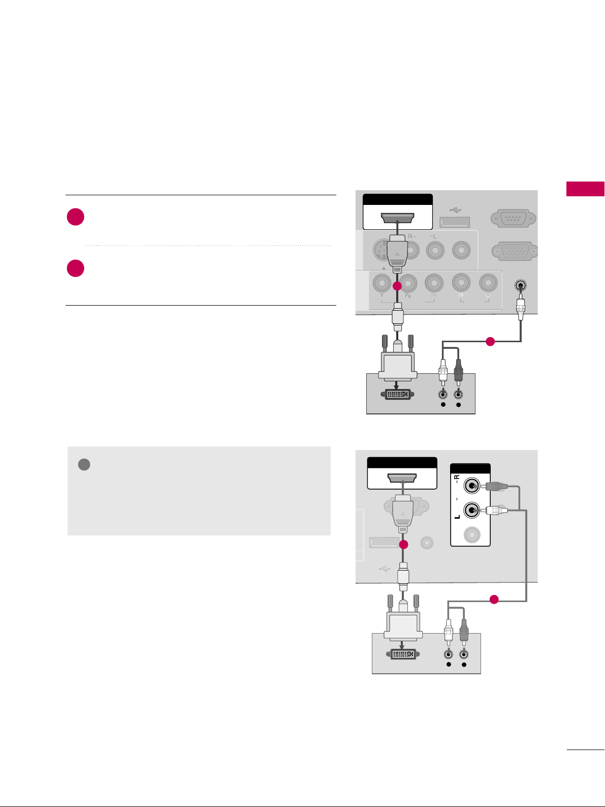
DVI to HDMI Connection
( )
( )
AUDIO IN
(RGB/DVI)
AUDIO IN
(RGB/DVI)
HDMI/DVI IN
USB IN
SERVUCE ONLY
VIDEO
MONO
( )
AUDIO
S-VIDEOS-VIDEO
RGB IN (PC)
RS-232C IN
(SERVICE ONLY)
RS-232C IN
(SERVICE ONLY)
AV IN 1AV IN 1
VIDEO
AUDIO
COMPONENT
IN
LR
DVI-DTV OUTPUT
L
R
1
2
GG
A DVI to HDMI cable or adapter is required for this
connection. DVI doesn't support audio, so a separate
audio connection is necessary.
NOTE
!
Connect the DVI output of the digital set-top box to
the
HHDDMMII //DDVV II II NN
jack on the TV.
Connect the audio output of the digital set-top box to
the
AAUUDD IIOO IINN (( RRGGBB //DDVV II))
or
AAVV IINN AAUU DD IIOO
jack
on the TV.
1. How to connect
2. How to use
■
Turn on the digital set-top box. (Refer to the owner’s manual for the digital set-top box.
)
■
Select the
HHDD MMII
input source on the TV using the
IINNPPUUTT
button on the remote control.
2
1
RS-232C INRS-232C IN
(SERVICE ONLY)(SERVICE ONLY)
USB INUSB IN
SERVUCE ONLYSERVUCE ONLY
REMOTEREMOTE
CONTROL OUTCONTROL OUT
AV IN 1AV IN 1
AUDIOAUDIO
MONOMONO
( )
RESETRESET
UPDATEUPDATE
AUDIOAUDIO
MONOMONO
( )
LR
DVI-DTV OUTPUT
L
R
HSPEAKER SWITCH
DVI AUDIO INDVI AUDIO IN
AV IN AV IN
VIDEOVIDEO
HDMI/DVI INHDMI/DVI IN
1
2
22LG3DCH model
26/32LG3DCH,
32LG3DC model
Page 26
EXTERNAL EQUIPMENT SETUP
24
EXTERNAL EQUIPMENT SETUP
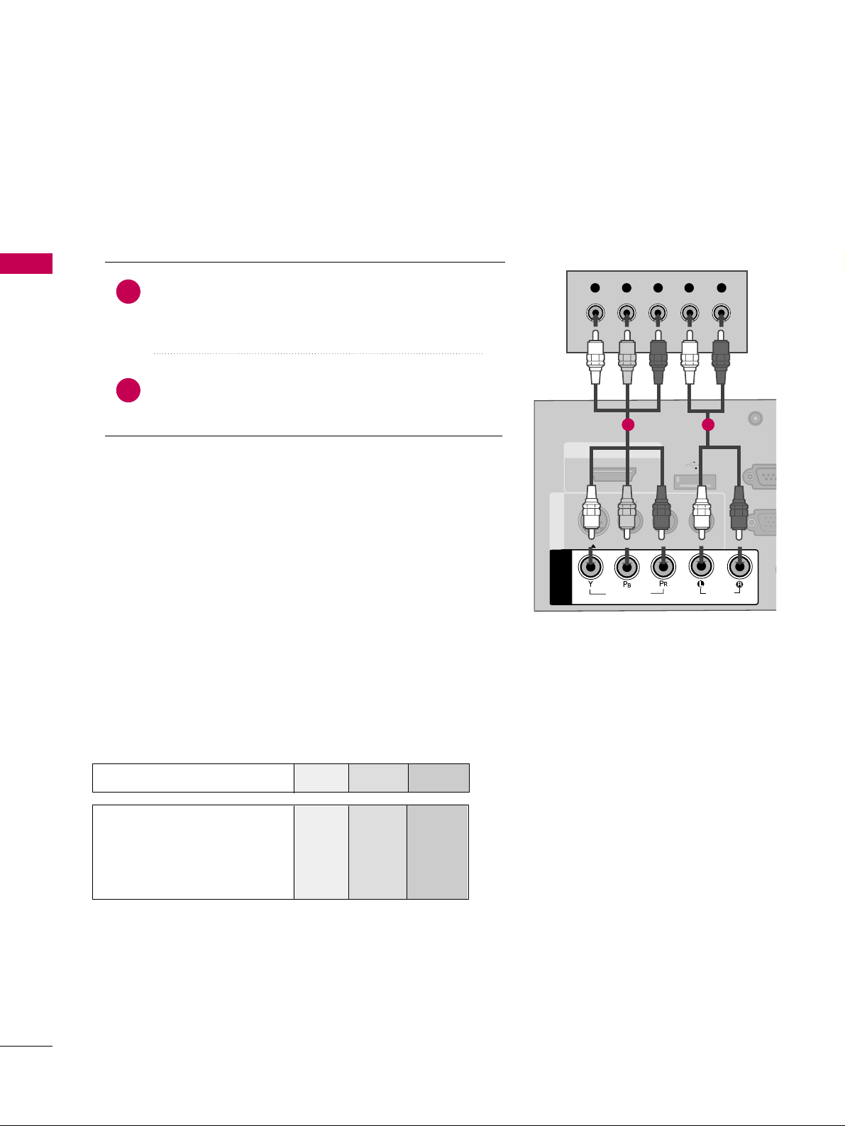
DVD SETUP
Component Connection
(Except 22LG3DCH)
Component Input ports
To get better picture quality, connect a DVD player to the component input ports as shown below.
Component ports on the TV
YPBP
R
Video output ports
on DVD player
Y
Y
Y
Y
PB
B-Y
Cb
Pb
PR
R-Y
Cr
Pr
Connect the video outputs (Y, PB
, PR
)
of the DVD to the
CC OOMMPPOO NNEENNTT IINN VV II DDEEOO
jacks on the TV.
Match the jack colors (Y = green, P
B = blue, and PR = red
)
.
Connect the audio outputs of the DVD to the
CC OOMMPPOO NNEENNTT IINN AAUU DDIIOO
jacks on the TV.
1. How to connect
2. How to use
■
Turn on the DVD player, insert a DVD.
■
Select the
CC oommppoonn eenn tt
input source on the TV using the
IINNPP UUTT
button on the remote control.
■
Refer to the DVD player's manual for operating instructions.
2
1
( )
AU
(RG
AUDIO IN
(RGB/DVI)
HDMI/DVI IN
USB IN
SERVUCE ONLY
VIDEO
MONO
( )
AUDIO
S-VIDEOS-VIDEO
RGB INRGB IN (PC)
RESET
UPDATEUPDATE
RS-23
(SERVIC
RS-232C IN
(SERVICE ONLY)
REMOTE
CONTROL OUT
SPEAKER OUT
8
AV IN 1AV IN 1
VIDEO
AUDIO
COMPONENT
IN
Y L RPBP
R
1 2
Page 27
EXTERNAL EQUIPMENT SETUP
25
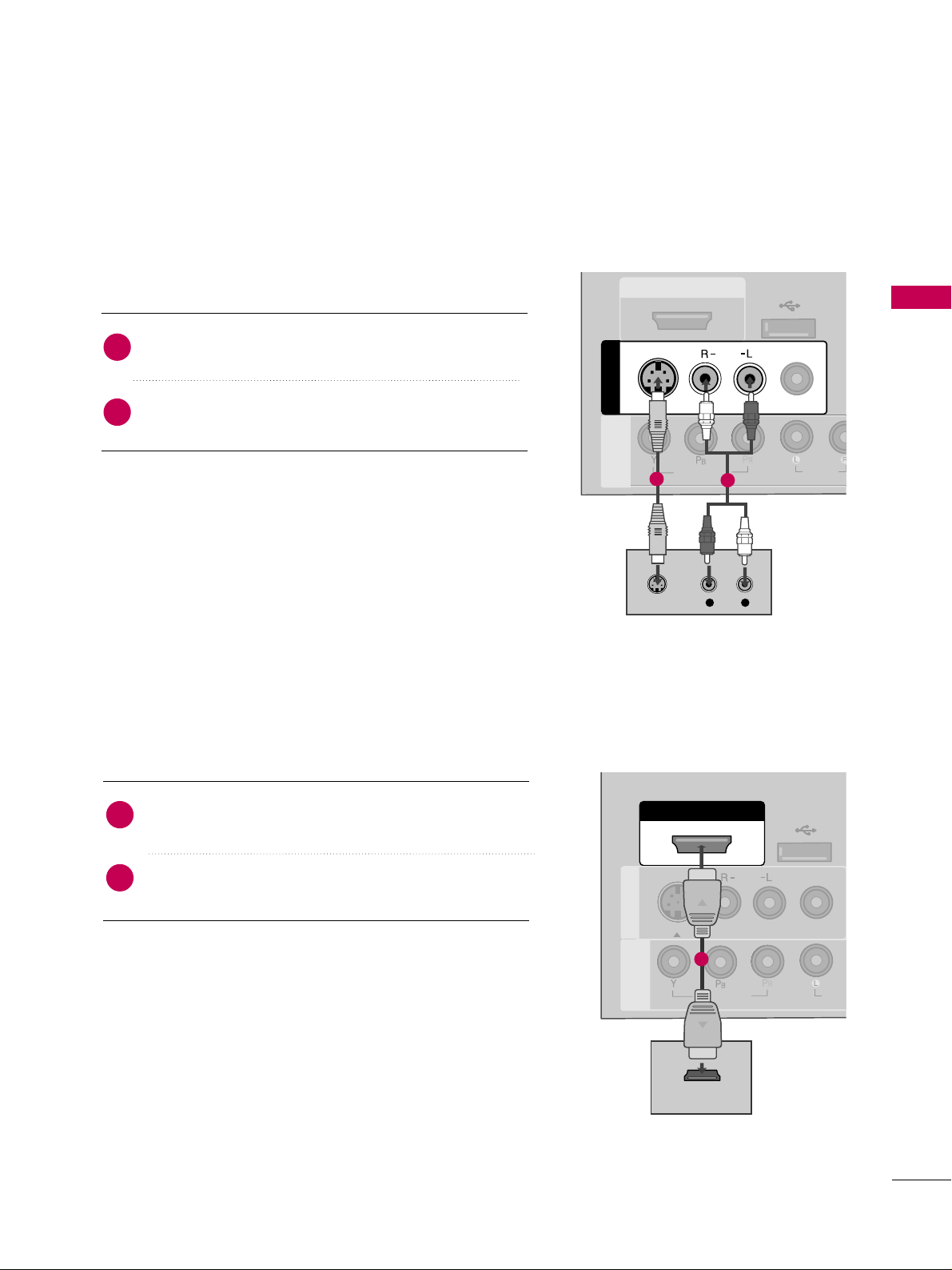
S-Video Connection
(Except 22LG3DCH)
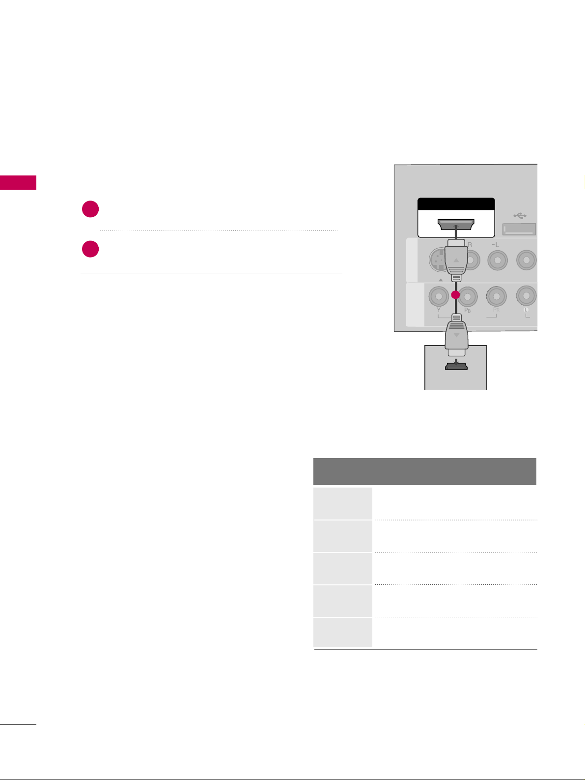
HDMI Connection
Connect the HDMI output of the DVD to the
HHDDMMII //DDVV II II NN
jack on the TV.
No separate audio connection is necessary.
HDMI supports both audio and video.
1. How to connect
2. How to use
■
Select the
HHDDMMII
input source on the TV using the
IINNPP UUTT
button on the remote control.
■
Refer to the DVD player's manual for operating instructions.
2
1
( )
L
R
S-VIDEO
AUDIO
HDMI/DVI IN
USB IN
SERVUCE ONLY
VIDEO
MONO
( )
AUDIO
AV IN 1AV IN 1
VIDEO
AUDIO
COMPONENT
IN
S-VIDEO
1
2
HDMI/DVI IN
USB IN
SERVUCE ONLY
VIDEO
MONO
( )
AUDIO
S-VIDEOS-VIDEO
RESET
UPDUPDATE
AV IN 1AV IN 1
VIDEO
AUDI
COMPONENT
IN
HDMI OUTPUT
1
Connect the S-VIDEO output of the DVD to the
SS --VV IIDD EEOO
input on the TV.
Connect the audio outputs of the DVD to the
AAUU DDIIOO
input jacks on the TV.
1. How to connect
2. How to use
■
Turn on the DVD player, insert a DVD.
■
Select the
AAVV 11
input source on the TV using the
IINNPP UUTT
button on the remote control.
■
Refer to the DVD player's manual for operating instructions.
2
1
Page 28
EXTERNAL EQUIPMENT SETUP
26
EXTERNAL EQUIPMENT SETUP
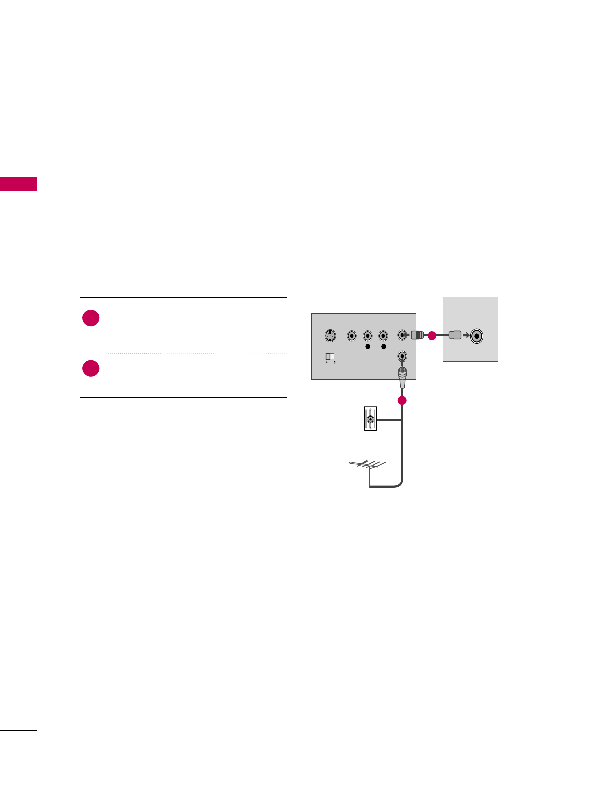
VCR SETUP
Antenna Connection
■
To avoid picture noise (interference), leave an adequate distance between the VCR and TV.
■
If the 4:3 picture format is used; the fixed images on the sides of the screen may remain visible on the
screen. This phenomenon is common to all TVs and is not covered by warranty.
L R
S-VIDEO VIDEO
OUTPUT
SWITCH
ANT IN
ANT OUT
ANTENNA IN
M.P.I.
Wall Jack
Antenna
1
2
Connect the RF antenna out socket of the
VCR to the
AANNTTEENNNNAA IINN
socket on the
TV.
Connect the antenna cable to the RF
antenna in socket of the VCR.
1. How to connect
2. How to use
■
Set VCR output switch to 3 or 4 and then
tune TV to the same channel number.
■
Insert a video tape into the VCR and press
PLAY on the VCR. (Refer to the VCR owner’s
manual.
)
2
1
Page 29
EXTERNAL EQUIPMENT SETUP
27
Composite (RCA) Connection
Connect the
AAUU DDIIOO/VVII DD EE OO
jacks between TV and
VCR. Match the jack colors (Video = yellow, Audio Left
= white, and Audio Right = red)
1. How to connect
2. How to use
■
Insert a video tape into the VCR and press PLAY on the
VCR. (Refer to the VCR owner’s manual.
)
■
Select the
AAVV orAAVV 11
input source on the TV using the
IINNPP UUTT
button on the remote control.
■
If connected to
AAVV IINN22
, select
AAVV 22
input source on the TV
(Except 22LG3DCH)
.
1
2. How to use
■
Insert a video tape into the VCR and press PLAY on the
VCR. (Refer to the VCR owner’s manual.
)
■
Select the
AAVV 11
input source on the TV using the
IINNPP UUTT
button on the remote control.
GG
If you have a mono VCR, connect the audio cable
from the VCR to the
AAUUDD IIOO LL ((MMOO NN OO))
jack of
the TV.
NOTE
!
AUDIO
(RGB/
VIDEO
MONO
( )
AUDIO
RGB IN (P
AV IN 1
AV IN 1
VIDEO
AUDIO
COMPONENT
IN
S-VIDEO
L
R
S-VIDEO
VIDEO
OUTPUT
SWITCH
ANT IN
ANT OUT
1
S-Video Connection
(Except 22LG3DCH)
Connect the
SS --VV IIDD EEOO
output of the VCR to the
SS --VV IIDD EEOO
input on the TV.
Connect the audio outputs of the VCR to the
AAUU DDIIOO
input jacks on the TV.
1. How to connect
2
1
ANTENNA IN
M.P.I.
VIDEO
MONO
( )
AUDIO
R
AV I N 1AV IN 1
VIDEO
AUDIO
COMPONENT
IN
S-VIDEO
L
R
S-VIDEO VIDEO
OUTPUT
SWITCH
ANT IN
ANT OUT
1
2
GG
Do not connect to both Video
and S-Video at the same time. In
the event that you connect both
Video and the S-Video cables,
only the S-Video will work.
CAUTION
GG
S-Video provides better quality than composite. Use
it when available.
NOTE
!
Page 30
EXTERNAL EQUIPMENT SETUP
28
EXTERNAL EQUIPMENT SETUP
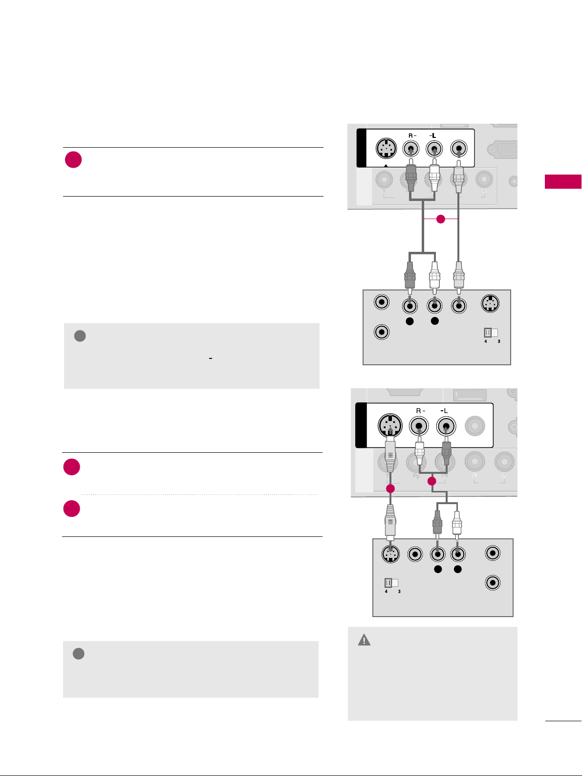
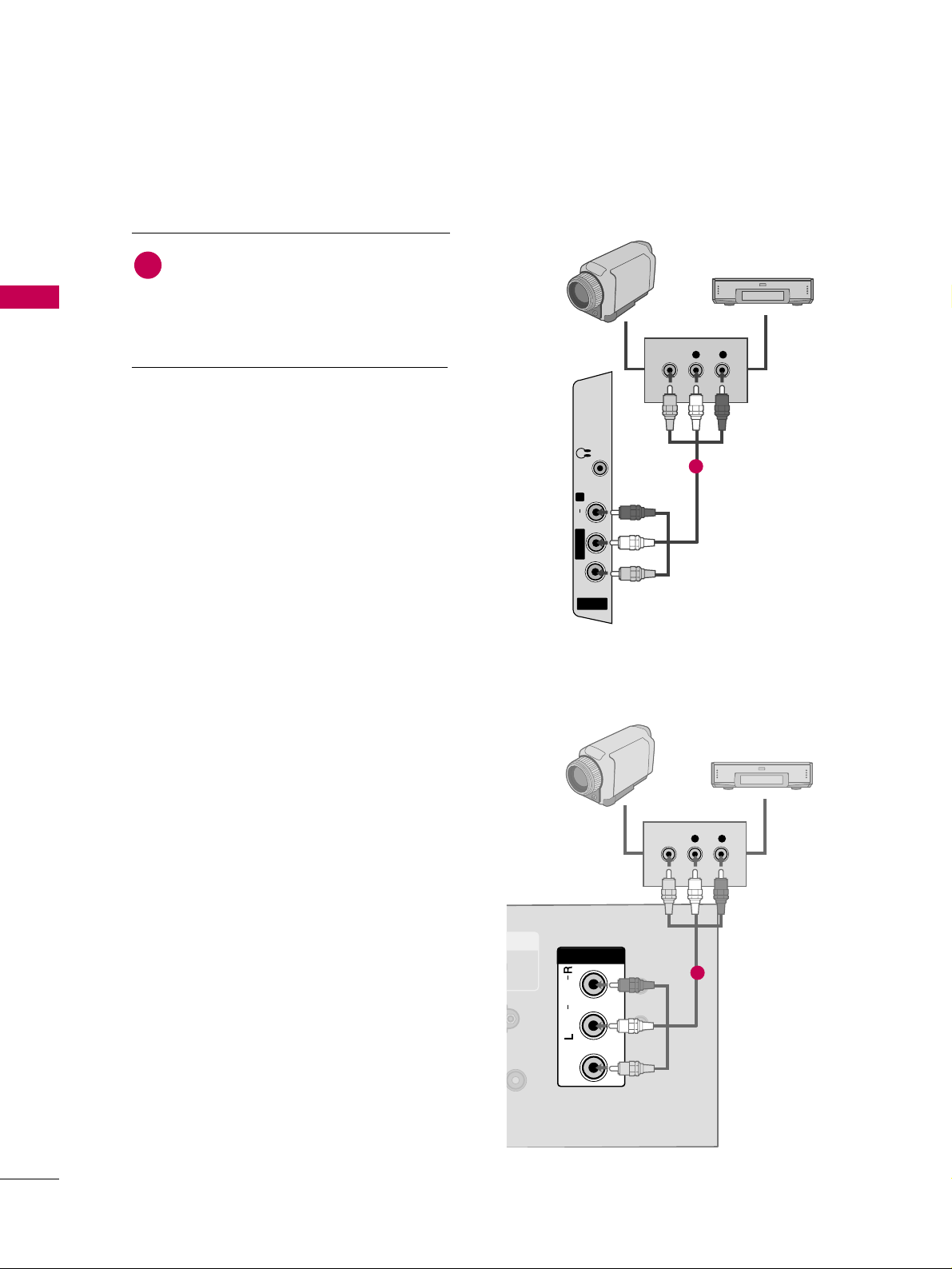
OTHER A/V SOURCE SETUP
AV IN 2
L/ MONO
R
AUDIO
VIDEO
H/P
L R
VIDEO
Camcorder
Video Game Set
Connect the
AAUUDDIIOO/VVIIDDEEOO
jacks
between TV and external equipment.
Match the jack colors
.
(
Video = yellow, Audio Left = white, and
Audio Right = red
)
1. How to connect
2. How to use
■
Select the
AAVV 22
input source on the TV using the
IINNPPUUTT
button on the remote control.
(Except
22LG3DCH)
■
If connected to
AAVV II NN orAAVV II NN 11
input, select
the
AAVV orAAVV 11
input source on the TV.
■
Operate the corresponding external equipment.
1
1
RESETRESET
UPDATEUPDATE
VIDEOVIDEO
AUDIOAUDIO
MONOMONO
( )
L R
VIDEO
DVI AUDIO INDVI AUDIO IN
AV IN AV IN
Video Game Set
1
Camcorder
22LG3DCH model
26/32LG3DCH,
32LG3DC model
Page 31

EXTERNAL EQUIPMENT SETUP
29
PILLOW SPEAKER SETUP
■
Connect a pillow speaker to the LCD TV/Monitor.
PILLOWPILLOW
SPEAKERSPEAKER
NORMALNORMAL
SPEAKERSPEAKER
PILLOWPILLOW
SPEAKERSPEAKER
SPEAKER SWITCHSPEAKER SWITCH
(Except 32LG3DC)
1. How to connect
Connect the
PPIILL LLOOWW SSPPEE AAKKEE RR
output jack on the
back of the TV.
Connect an acccessory pillow speaker or wired remote
control unit to this 6-pin jack.
Select
PPIILL LLOOWW SSPP EEAAKK EERR
on the rear panel of the
TV.
2
1
3
■
NOTE:
If the pillow speaker switch is set to Pillow Speaker, no
sound will be heard from the TV speakers. Also, Auto Volume will
be grayed out and not accessible on the Sound menu.
Use a pillow speaker that is a UL recognized pendant control
bearing the warning:
“Risk of fire if used in oxygen enriched atmosphere. Keep pen-
dant control away from oxygen equipment.”
Controlling the TV with Serial Data
The TV is capable of being controlled by a single-wire, serial data
signal. This is a LG patented technology and is being implemented
by certain brands of “smart” pillow speakers.
Pillow Speaker Interface
This connector furnishes three control lines and an audio output.
A patient-pendant remote control, or entertainment audio and
nurse call system may be connected here. All lines are isolated
from the AC power line and earth ground. (Optoisolators isolate
the control lines, and a transformer isolates the audio. There are
no relays or inductive components in the control lines.)
Controlling the TV with Mechanical Switches
Pin 4(common) is momentarily connected to pin
1, 3, or 6 via push-action switches to control
On/Off and Channel Up/Down. These pins are
at +13volts DC(when measured from pin4) with
the switches open. Current draw is 8 mA when a
switch is closed. (This operation is identical to
previous LG models using the 5-Wire Interface
except that only +7 volts DC was supplied and
current draw was only 2.5 mA.)
pin No.
1
2
3
4
5
6
External TV On/Off switch.
(Not used.)
External Channel Up switch or Data in.
Common connection for control, data, and
audio output. Impedance to earth ground is a
10-meg resistor in parallel with a 1100 pf
capacitor.
Isolated audio output. Nominal 14-ohm source
impedance with short circuit protection.
Intended for a pillow speaker with a low-impe
ance pad-type volume control.
External Channel Down switch.
Purpose
Page 32

EXTERNAL EQUIPMENT SETUP
30
EXTERNAL EQUIPMENT SETUP
PC SETUP
Horizontal Vertical
Frequency(KHz)Frequency(Hz
)
31.469 70.08
31.469 70.08
31.469 59.94
37.879 60.31
48.363 60.00
47.776 59.87
47.712 60.01
47.720 59.799
47.130 59.65
GG
To get the the best picture quality, adjust the PC
graphics card to 1360x768.
GG
Depending on the graphics card, DOS mode may
not work if a HDMI to DVI Cable is in use.
GG
In PC mode, there may be noise associated with the
resolution, vertical pattern, contrast or brightness.
If noise is present, change the PC output to another resolution, change the refresh rate to another
rate or adjust the brightness and contrast on the
PICTURE menu until the picture is clear.
GG
Avoid keeping a fixed image on the screen for a
long period of time. The fixed image could become
permanently imprinted on the screen.
GG
The synchronization input form for Horizontal and
Vertical frequencies is separate.
GG
Depending on the graphics card, some resolution
settings may not allow the image to be positioned
on the screen properly.
NOTES
!
Supported Display Specifications
(RGB-PC, HDMI-PC)
Resolution
720x400
1360x768
640x350
640x480
800x600
1024x768
1366x768
1280x768
* Only RGB-PC mode
This TV provides Plug and Play capability, meaning that the PC adjusts automatically to the TV's settings.
VGA (D-Sub 15 pin) Connection
(Except 22LG3DCH)
RGB OUTPUT
AUDIO
AUDIO IN
(RGB/DVI)
AUDIO IN
(RGB/DVI)
VIDEO
RGB IN (PC)RGB IN (PC)
REMOT
CONTROL
AUDIOAUDIO
1
2
2. How to use
■
Turn on the PC and the TV.
■
Select the
RR GG BB
input source on the TV using the
IINNPP UUTT
button on the remote control.
Connect the VGA output of the PC to the
RR GG BB
II NN((PP CC
))
jack on the TV.
Connect the PC audio output to the
AAUU DD IIOO IINN
((
RRGG BB// DD VVII
))
jack on the TV.
1. How to connect
2
1
Page 33

EXTERNAL EQUIPMENT SETUP
31
DVI to HDMI Connection
( )
AUDIO IN
(RGB/DVI)
AUDIO IN
(RGB/DVI)
HDMI/DVI IN
USB IN
SERVUCE ONLY
VIDEO
MONO
( )
AUDIO
S-VIDEOS-VIDEO
RGB IN (PC)
UPDATE
RS-232C IN
(SERVICE ONLY)
AV IN 1AV IN 1
VIDEOVIDEO
AUDIOAUDIO
COMPONENT
IN
DVI-PC OUTPUT AUDIO
1
2
2. How to use
■
Turn on the PC and the TV.
■
Select the
HHDDMMII
input source on the TV using the
IINNPP UUTT
button on the remote control.
Connect the DVI output of the PC to the
HHDDMM II //DDVV II
IINN
jack on the TV.
Connect the PC audio output to the
AAUU DDIIOO II NN
((RRGGBB//DDVV II )) orAAVV IINN AAUUDD IIOO
jack on the TV.
1. How to connect
2
1
RS-232C INRS-232C IN
(SERVICE ONLY)(SERVICE ONLY)
USB INUSB IN
SERVUCE ONLYSERVUCE ONLY
REMOTEREMOTE
CONTROL OUTCONTROL OUT
AV IN 1AV IN 1
AUDIOAUDIO
MONOMONO
( )
UPDATEUPDATE
RESETRESET
AUDIOAUDIO
MONOMONO
( )
DVI-PC OUTPUT AUDIO
DVI AUDIO INDVI AUDIO IN
HDMI/DVI INHDMI/DVI IN
AV IN AV IN
VIDEOVIDEO
1
2
22LG3DCH model
26/32LG3DCH,
32LG3DC model
Page 34

EXTERNAL EQUIPMENT SETUP
32
EXTERNAL EQUIPMENT SETUP
Screen Setup for PC mode
(Except 22LG3DCH)
Select the desired resolution.
1024 x 768
1280 x 768
1360 x 768
1366 x 768
Auto config.
Resolution
G
Position
Size
Phase
Reset
Screen
Move
Prev.
MENU
1
ADJUST
3
4
2
ENTER
RETURN
Select
RReessoo lluu ttii oo nn
.
Selecting Resolution
You can choose the resolution in RGB mode.
The
PPooss iittiioo nn, PPhh aassee
, and
SS iizzee
can also be adjusted.
Press the
AADDJJ UUSS TT
button.
Return to TV viewing.
■
You can also adjust
SSccrr ee ee nn((RRGG BB-- PPCC ))
in the
PPIICCTTUURREE
menu.
Page 35

EXTERNAL EQUIPMENT SETUP
33
Auto Configure
Automatically adjusts picture position and minimizes image instability. After adjustment, if the image is still
not correct, try using the manual settings or a different resolution or refresh rate on the PC.
Select
AAuutt oo cc oonn ffiigg..
.
Auto config.
G
Resolution
Position
Size
Phase
Reset
Screen
Move
Prev.
MENU
To Set
3
2
Select
YYee ss
.
4
ENTER
Start Auto Configuration.
ENTER
Press the
AADDJJ UUSS TT
button.
1
• If the position of the image is still not
correct, try Auto adjustment again.
• If picture needs to be adjusted again
after Auto adjustment in RGB, you can
adjust the
PPooss ii tt ii oonn, SSii zz ee
or
PPhh aa ss ee
.
Yes No
ADJUST
Page 36

EXTERNAL EQUIPMENT SETUP
34
EXTERNAL EQUIPMENT SETUP
Adjustment for screen Position, Size, and Phase
If the picture is not clear after auto adjustment and especially if characters are still trembling, adjust the picture
phase manually.
This feature operates only in RGB mode.
Make appropriate adjustments.
Auto config.
Resolution
Position
G
Size
Phase
Reset
GF
D
E
Screen
Move
Prev.
MENU
3
ENTER
4
RETURN
■
PPooss ii tt ii oonn
: This function is to adjust picture to left/right and up/down as you
prefer.
■
SSii zzee
: This function is to minimize any
vertical bars or stripes visible on the
screen background. And the horizontal
screen size will also change. The
SSiizzee
adjustment range is
--3300
~
3300
.
■
PPhh aa ss ee
: This function allows you to
remove any horizontal noise and clear or
sharpen the image of characters. The
PPhhaassee
adjustment range is
--3322
~
3311
.
Press the
AADDJJ UUSS TT
button.
Select
PPooss ii tt ii oonn, SSii zzee
, or
PPhh aa ss ee
.
1
ADJUST
2
Return to TV viewing.
Page 37

EXTERNAL EQUIPMENT SETUP
35
Screen Reset (Reset to original factory values)
Returns
PPoo ssii ttiioonn, SS iizzee
, and
PPhhaassee
to the default factory settings.
This feature operates only in RGB mode.
3
ENTER
Select
RReesseett
.
1
ADJUST
2
Select
YYee ss
.
4
ENTER
Auto config.
Position
Resolution
Size
Phase
Reset
G
Screen
Move
Prev.
MENU
Initialize Settings.
Yes No
Press the
AADDJJ UUSS TT
button.
Page 38

WATCHING TV / CHANNEL CONTROL
36
REMOTE CONTROL FUNCTIONS
WATCHING TV / CHANNEL CONTROL
When using the remote control, aim it at the remote control sensor on the TV.
123
456
780-9
VOL CH
ENTER
POWER
MUTE
MENU
ADJUST
RETURN
CC
SAP
FLASHBK
PICTURE
SOUND
RATIO
TV
INPUT
TIMER
POWER
TV
INPUT
PICTURE
SOUND
SAP
RATIO
Turns your TV on or off.
In AV1-2, Component, RGB, and HDMI input sources, screen
returns to the last TV channel.
External input modes rotate in regular sequence: TV, AV12, Component, RGB, and HDMI.
Selects the factory preset picture depend on the viewing
environment.
GG
pp..5511
Selects the factory preset sound for type of program.
GG
pp..6611
Analog mode: Selects MTS sound (Mono, Stereo, or a
SAP).
GG
pp..6677
DTV mode: Changes the audio language.
Change the aspect ratio.
GG
pp..4488
THUMBSTICK
(Up/Down/Left
Right/ENTER)
Navigate the on-screen menus and adjust the system settings to your preference.
(Only 32LG3DC)
Page 39

WATCHING TV / CHANNEL CONTROL
37
Installing Batteries
■
Open the battery compartment cover on the back side and install
the batteries matching correct polarity (+with +,-with -).
■
Install two 1.5V AAA batteries. Don’t mix old or used batteries with
new ones.
■
Close cover.
NUMBER button
— (DASH)
FLASHBK
Used to enter a program number for multiple program channels such as 2-1, 2-2, etc.
Tune to the last channel viewed.
VOLUME UP
/DOWN
TIMER
CC
MUTE
CHANNEL
UP/DOWN
ADJUST
MENU
RETURN
Increase/decrease the sound level.
Select the amount of time before your TV turns off automatically.
GG
pp..7766
Select a closed caption.
GG
pp..7700
Switch the sound on or off.
GG
pp..4411
Select available channels.
Adjust the screen resolution, position, size and phase.
GG
pp..3322 -- pp..3355
Displays the main menu.
Allows the user to move return one step in an interactive application or other user interaction function.
Page 40

WATCHING TV / CHANNEL CONTROL
38
INSTALLER REMOTE CONTROL FUNCTIONS
WATCHING TV / CHANNEL CONTROL
ENTER
TVTV
INPUT
INPUT MODE
DVD
MULTI
EXIT
VOL
EZ SOUND
INFO
SWAP
EZ PIC
TIMER
MUTE
CH
SAP
CC
RATIO
MENU
VCR
POWER
123
456
789
0
FLASH
BACK
PAG E
TV INPUT/INPUT
POWER
MULTI
MODE
Select available input sources.
Turns your TV or any other programmed
equipment On or Off, depending on mode.
Selects available auxiliary input sources.
Adjusts picture brightness.
Selects remote operating mode: TV, VCR, or DVD. Select
these other operating modes for remote to operate external
devices.
VOLUME
UP/DOWN
CHANNEL
UP/DOWN/PAGE
TIMER
MUTE
NUMBER
Buttons (0 - 9)
— (DASH)
FLASHBK
Increases/decreases the sound level.
Selects available channels found with Auto tuning.
Moves to next available page.
Sets the amount of time before the TV automatically
turns itself Off.
Switches the sound on or off.
Use to enter a program number or channels.
Dash for multiple channels such as 9-1, 9-2, etc.
Returns to the previously viewed channel.
Use the MODE button to select TV and put installer remote into TV operating
mode.
Notes: This remote is not supplied with the TV. This typical LG multi-brand
remote control is shown for reference.
Follow the instructions provided in the Installer menu section to configure the
TV’s features.
All features shown may not be available on all TVs.
LG Multi-brand Remote Control
Page 41

WATCHING TV / CHANNEL CONTROL
39
EZ PIC
EZ SOUND
SWAP
INFO
VCR/DVD
BUTTONS
Selects the factory preset picture appropriate for the viewing environment.
Sets the appropriate sound for the program’s content.
Exchanges the main/sub images in Twin picture mode.
While watching a TV program, will display program information on top of the screen.
Info feature is not functional for Aux sources.
Control some video cassette recorders or DVD players. (“RECORD” is not functional in DVD
mode.) Set up for VCR recording: Once, Regularly, Weekly, Off. (“RECORD” button only).
MENU
CC
EXIT
RATIO
SAP
THUMBSTICK
(Up/Down/Left
Right/ENTER)
Brings up the main menu to the screen.
Enters or exits a Panel Menu in the TV Guide on-screen menu system.
Selects a closed caption option: Off, CC1
~ 4, Text1 ~ 4.
Clears all on-screen displays and returns to TV viewing from any TV menu.
Adjusts the picture aspect ratio.
Selects MTS sound:
Mono, Stereo, and SAP in Analog mode.
Changes the audio language in DTV mode.
Use to navigate on-screen menus / adjust the system settings to your requirements.
Installing Batteries in Installer Remote Control
■
Remove the battery compartment cover on the back side by sliding the cover downward until the batteries are exposed and can be
removed. Install new batteries matching correct polarity as shown
(+ with + and - with -). Slide cover back into position to close
compartment.
■
Install two high-quality 1.5V AAA batteries. Never mix old or used
batteries with new ones. Replace cover.
AAA +
+ AAA
Page 42

WATCHING TV / CHANNEL CONTROL
40
WATCHING TV / CHANNEL CONTROLWATCHING TV / CHANNEL CONTROL
NOTE
!
GG
If you intend to be away on vacation, disconnect the power plug from the wall power outlet.
TURNING ON TV
First, connect power cord correctly.
At this moment, the TV switches to standby mode.
■
In standby mode to turn TV on, press the button on the TV or press
the
PPOO WW EE RR
button on the remote control.
■
Note: Only for 32LG3DCH the TV also turn on with
CCHH ((++
or
--))
button on the remote.
Select the viewing source by using the
IINNPPUUTT
button on the remote control.
■
This TV is programmed to remember which power state it was last set to,
even if the power cord is out.
When finished using the TV, press the
PPOO WW EE RR
button on the remote con-
trol. The TV reverts to standby mode.
1
2
3
Page 43

WATCHING TV / CHANNEL CONTROL
41
Press the
CCHH ((++
or
--))
or
NNUUMMBBEERR
buttons to select a channel number.
1
VOLUME ADJUSTMENT
CHANNEL SELECTION
Press the
VVOOLL ((++
or
--))
button to adjust the volume.
If you want to switch the sound off, press the
MMUUTTEE
button.
You can cancel the Mute function by pressing the
MMUUTTEE
or
VVOOLL ((++
or
--))
button.
Adjust the volume to suit your personal preference.
1
2
3
Page 44

WATCHING TV / CHANNEL CONTROL
42
WATCHING TV / CHANNEL CONTROL
ON-SCREEN MENUS SELECTION
Your TV's OSD (On Screen Display) may differ slightly from that shown in this manual.
Display each menu.
Select a menu item.
Enter to the pop up menu.
1
MENU
3
2
ENTER
ENTER
Return to TV viewing.
4
MENU
Enter
Move
CHANNEL
CHANNEL
TIME
PICTURE
OPTION
AUDIO
LOCK
Enter
Move
Aspect Ratio : 16:9
Picture Mode : Standard
• Backlight 80
• Contrast 90
• Brightness 50
• Sharpness 60
• Color 60
• Tint 0
PICTURE
E
Enter
Move
Auto Volume : Off
Clear Voice : On
Balance 0
Sound Mode : Standard
•
SRS TruSurround XT:
Off
• Treble 50
• Bass 50
• Reset
AUDIO
E
LR
Enter
Move
Clock :
Feb/21/2008/ 2:10 AM
Off Time : Off
On Time : Off
Sleep Timer : Off
Auto Sleep : Off
TIME
Enter
Move
Lock System : Off
Set Password
Block Channel
Movie Rating
TV Rating-Children
TV Rating-General
Downloadable Rating
Input Block
LOCK
RG
Auto Tuning
Manual Tuning
Channel Edit
Channel Label
Enter
Move
Language : English
Caption : Off
OPTION
Page 45

WATCHING TV / CHANNEL CONTROL
43
CHANNEL SETUP
Auto Scan (Auto Tuning)
Automatically finds all channels available through antenna or cable inputs, and stores them in memory on the
channel list.
Run Auto Tuning again after any Antenna/Cable connection changes.
Select
CC HHAANNNNEE LL
.
Select
AAuu tt oo TT uunn iinn gg
.
Select
YYee ss
.
Run
AAuu tt oo tt uunniinngg
.
1
MENU
3
2
ENTER
ENTER
4
ENTER
■
A password is required to gain access to
Auto Tuning menu if the Lock System is
turned on.
5
RETURN
Return to the previous menu.
MENU
Return to TV viewing.
Enter
Move
CHANNEL
Auto Tuning
Manual Tuning
Channel Edit
Channel Label
Enter
Move
CHANNEL
Auto Tuning
Manual Tuning
Channel Edit
Channel Label
Press ‘Yes’ button to begin
auto tuning.
Yes
No
Page 46

WATCHING TV / CHANNEL CONTROL
44
WATCHING TV / CHANNEL CONTROL
Select
CC HHAANNNNEE LL
.
1
MENU
2
ENTER
If selecting DTV or CADTV input signal, you can view the on-screen signal strength monitor to see the quality
of the signal being received.
Add/Delete Channel (Manual Tuning)
Select
MMaa nnuu aall TTuu nniinn gg
.
Select
DDIIGG II TTAA LL
or
AANNAA LLOO GG
.
Select channel you want to add
or delete.
3
ENTER
4
Select
AAdddd
or
DDeell ee ttee
.
5
ENTER
■
A password is required to gain access to
Manual Tuning menu if the Lock System
is turned on.
6
RETURN
Return to the previous menu.
MENU
Return to TV viewing.
Enter
Move
CHANNEL
Enter
Move
CHANNEL
Auto Tuning
Manual Tuning
Channel Edit
Channel Label
Channel
Select channel type and
RF-channel number.
FF
DIGITAL
GG
FF
2
GG
Close
Delete
DIGITAL 2-1
Bad Normal Good
Auto Tuning
Manual Tuning
Channel Edit
Channel Label
Page 47

WATCHING TV / CHANNEL CONTROL
45
Select a channel.
Select channel you want to add or delete.
3
ENTER
4
ENTER
A custom list can be created by toggling each channel on or off with ENTER button. The channels in the Custom
List are displayed in black and the channels deleted from the Custom List are displayed in gray.
Once a channel is highlighted you can add or delete the channel by referring to the small window at the topright corner of the screen.
Channel Editing
Select
CC HHAANNNNEE LL
.
1
MENU
2
ENTER
Select
CC hhaannnn ee ll EE dd iitt
.
RETURN
Return to TV viewing.
Return to the previous menu.
5
MENU
Add/Delete
Move Page
CH
Move
Previous
RETURN
EXIT
MENU
Enter
Move
CHANNEL
Auto Tuning
Manual Tuning
Channel Edit
Channel Label
+
Page 48

WATCHING TV / CHANNEL CONTROL
46
WATCHING TV / CHANNEL CONTROL
CHANNEL LABEL
Choose preset labels for your channels.
If a channel label is provided on the signal from the broadcasting station, the TV displays a short name for a
channel even if you didn't preset a label for the channel.
Enter
Move
CHANNEL
Auto Tuning
Manual Tuning
Channel Edit
Channel Label
Enter
Move
CHANNEL
Auto Tuning
Manual Tuning
Channel Edit
Channel Label
Logo
FF
Disney
GG
Channel
DIGITAL 2-1
Close
Select
CC HHAANNNNEE LL
.
Select
CC hhaannnn ee ll LL aa bb ee ll
.
Select Channel.
1
MENU
3
2
ENTER
ENTER
Select the appropriate logo for the channel.
5
Select a channel to set logo.
4
6
RETURN
Return to the previous menu.
MENU
Return to TV viewing.
Page 49

WATCHING TV / CHANNEL CONTROL
47
INPUT LIST
Select the desired input source.
1
INPUT
TV AV1 AV2
Component
HDMI RGB
TV AV1 AV2 Component RGB
ENTER
■
TT VV
: Select it to watch over-the-air, cable
and digital cable broadcasts.
■
AAVV 11--22
: Select them to watch a VCR or
other external equipment.
■
CC oo mmppoonn eenn tt
: Select them to watch
DVD or a Digital set-top box.
■
RR GG BB
: Select it to view PC input.
■
HHDD MMII
: Select them to watch high defin-
ition devices.
TV AV
HDMI
For 26/32LG3DCH
32LG3DC
For 22LG3DCH
Page 50

PICTURE CONTROL
48
PICTURE SIZE (ASPECT RATIO) CONTROL
PICTURE CONTROL
This feature lets you choose the way an analog picture with a 4:3 aspect ratio is displayed on your TV.
■
RGB input source use 4:3 or 16:9 aspect ratio.
NOTE
!
GG
If a fixed image is displayed on the screen for a long time, the image could become imprinted on the
screen and remain visible. This phenomenon is rare on LCDs, but is possible when the image is on the
screen for a very long time. This phenomenon is common to all manufacturers and is not covered by
warranty. When watching video that does not fill the screen, any after-image from the black bars will
normally dissipate after a few minutes.
Press the
RRAA TTIIOO
button repeatedly to select the picture options
:
SSee tt BByy PPrroogg rraamm,, 44:: 33,, 1166:: 99,, FF uull ll
(Only 22LG3DCH)
,, ZZoo oo mm11,, ZZoooomm22,,
JJuusstt SScc aa nn
.
1
RATIO
2
RETURN
Return to TV viewing.
1166::99
■
You can also adjust
AAss pp ee cctt RR aa tt iioo
in
the
PPIICCTTUURREE
menu.
Page 51

PICTURE CONTROL
49
Set by program
Selects the proper picture proportion to match
the source’s image.
4:3
Choose 4:3 when you want to view a picture
with an original 4:3 aspect ratio.
16 : 9
Adjust the picture horizontally, in a linear proportion to fill the entire screen.
Full
(Only 22LG3DCH)
When TV receives the wide screen signal, it will lead
you to adjust the picture horizontally or vertically,
in a linear proportion, to fill the entire screen fully.
(4:3 4:3)
(16:9 16:9)
Page 52

PICTURE CONTROL
50
PICTURE CONTROL
Zoom 1
Choose Zoom 1 when you want to view the picture without any alteration. However, the top and
bottom portions of the picture will be cropped.
Zoom 2
Choose Zoom 2 when you want the picture to be
altered, both vertically extended and cropped.
The picture taking a halfway trade off between
alteration and screen coverage.
Just Scan
Normally the edges of video signals are cropped
1-2%. Just Scan turns off this cropping and
shows the complete video.
Notes: If there is noise on the edges of the original
signal, it will be visible when Just Scan is activated.
JJuusstt SScc aa nn
operates only with
DTV/CADTV/HDMI-DTV/DVI-DTV
(720p/1080i/1080p),
Component(720p/1080i) input sources.
Page 53

PICTURE CONTROL
51
PRESET PICTURE SETTINGS
Picture Mode - Preset
There are factory presets for picture settings available in the user menus. You can use a preset, change each
setting manually.
1
PICTURE
Press the
PPIICCTTUURREE
button repeatedly to select the picture options
:
VVii vvii dd,SSttaannddaarrdd, CCiinn eemmaa, SSpp oo rrtt, GGaammee
and
EExx ppeerr tt 11-- 22
.
■
You can also adjust
PPii cc ttuu rree MMoo dd ee
in
the
PPIICCTTUURREE
menu.
Return to TV viewing.
2
RETURN
VVii vvii dd
Page 54

PICTURE CONTROL
52
PICTURE CONTROL
Color Tone - Preset
Choose one of three automatic color adjustments. Set to warm to enhance hotter colors such as red, or set to
cool to see less intense colors with more blue.
Select
PPIICCTTUU RREE
.
Select
CC oolloorr TTeemmpp eerraatt uurr ee
.
1
MENU
3
ENTER
Select
CC oo oo ll, MMee dd ii uumm
, or
WW aarr mm
.
4
Select
AAddvvaann cceedd CCoo nnttrrooll
.
2
ENTER
5
RETURN
Return to the previous menu.
MENU
Return to TV viewing.
Enter
Move
PICTURE
EE
RG
• Contrast 50
• Brightness 50
• Sharpness 50
• Color 50
• Tint 0
• Advanced Control
• Reset
Screen (RGB-PC)
Enter
Move
PICTURE
E
RG
• Contrast 50
• Brightness 50
• Sharpness 50
• Color 50
• Tint 0
• Advanced Control
• Reset
Screen (RGB-PC)
Color Temperature
FF
Medium
GG
Fresh Contrast
Off
Fresh Color
Off
Noise Reduction
Auto
Gamma
Medium
Black Level
Medium
Real Cinema
Off
Close
Page 55

PICTURE CONTROL
53
MANUAL PICTURE ADJUSTMENT
Picture Mode - User Mode
Adjust the picture appearance to suit your preference and viewing situations.
Select
PPIICCTTUU RREE
.
Make appropriate adjustments.
Select
BBllaacckklliigg hhtt,, CCoonnttrraass tt ,, BBrr iigghhttnnee ssss,,
SShhaarrppnnee ssss ,, CCoolloorr ,, oorr TT iinn tt..
1
MENU
Select
PPii cc ttuu rree MMoo dd ee
.
2
ENTER
Select
VVii vvii dd,SSttaannddaarrdd, CCiinn eemmaa, SSpp oo rrtt
, or
GGaammee
.
3
ENTER
4
ENTER
5
ENTER
6
RETURN
Return to the previous menu.
Return to TV viewing.
Enter
Move
PICTURE
E
Aspect Ratio : 16:9
Picture Mode : Standard
• Backlight 90
• Contrast 90
• Brightness 50
• Sharpness 60
• Color 60
• Tint 0
• Backlight 80
EE
EE
EE
EE
Enter
RG
MENU
Page 56

PICTURE CONTROL
54
PICTURE CONTROL
Picture Mode - Expert Control
Select your desired menu option.
Select
PPIICCTTUU RREE
.
Select
PPii cc ttuu rree MMoo dd ee
.
Select
EExxpp ee rrtt CCoo nnttrrooll
.
Select
EExxpp ee rr tt 11
or
EExxpp ee rr tt 22
.
1
MENU
3
2
ENTER
ENTER
4
ENTER
5
ENTER
Make appropriate adjustments.
6
EExx ppeerrtt11
and
EExx ppeerrtt22
allow you set you own custom settings.
7
RETURN
Return to the previous menu.
Return to TV viewing.
Enter
Move
PICTURE
E
Aspect Ratio : 16:9
Picture Mode : Standard
• Backlight
• Contrast 90
• Brightness 50
• Sharpness 60
• Color 60
• Tint 0
RG
Enter
Move
PICTURE
Vivid
Standard
Cinema
Sport
Game
Expert1
Expert2
E
MENU
• Contrast 90
• Brightness 50
• Sharpness 60
• Color 60
• Tint 0
• Expert Control
• Reset
Screen (RGB-PC)
RG
FF
Off
GG
Fresh Contrast
Noise Reduction
Off
Gamma
Medium
Black Level
Auto
Off
Real Cinema
Color Standard
HD
White Balance
Normal
Red Contrast
50
E
Page 57

PICTURE CONTROL
55
PICTURE IMPROVEMENT SETTINGS
Fresh Contrast: Optimizes the contrast automatically according to the brightness of the reflection.
Fresh Color: Adjusts the color of the reflection automatically to reproduce as close as possible natural colors.
Noise Reduction: Removes interference up to the point where it does not damage the original picture.
Gamma: High gamma values display whitish images and low gamma values display high contrast images.
Select
PPIICCTTUU RREE
.
Select
AAddvvaann cceedd CCoo nnttrrooll
.
Select
FF rreesshh CCoonn ttrr aa ss tt, FF rr eesshh CC oolloo rr
,
NNoo iissee RR ee dd uucctt iioonn
, or
GGaammmmaa
.
1
MENU
3
2
ENTER
ENTER
5
RETURN
Return to the previous menu.
Return to TV viewing.
Select your desired options.
4
Enter
Move
PICTURE
E
RG
• Contrast 50
• Brightness 50
• Sharpness 50
• Color 50
• Tint 0
• Advanced Control
• Reset
Screen (RGB-PC)
Enter
Move
PICTURE
E
RG
• Contrast 50
• Brightness 50
• Sharpness 50
• Color 50
• Tint 0
• Advanced Control
• Reset
Screen (RGB-PC)
MENU
Color Temperature
FF
Medium
GG
Fresh Contrast
Off
Fresh Color
Off
Noise Reduction
Auto
Gamma
Medium
Black Level
Medium
Real Cinema
Off
Close
Medium
FF
Off
GG
Page 58

PICTURE CONTROL
56
PICTURE CONTROL
ADVANCED CONTROL - BLACK (DARKNESS) LEVEL
Adjusting the contrast and the brightness of the screen using the black level of the screen.
This feature is disable in DTV and RGB mode.
Select
PPIICCTTUU RREE
.
Select
AAddvvaann cceedd CCoo nnttrrooll
.
Select
BBllaacc kk LLeevv eell
.
1
MENU
3
2
ENTER
ENTER
Select
LLoo ww
or
HHii gg hh
.
4
■
LLoo ww
: The reflection of the screen gets
darker.
■
HHii gg hh
: The reflection of the screen gets
brighter.
■
AAuu ttoo
: Realizing the black level of the
screen and set it to High or Low automatically.
5
RETURN
Return to the previous menu.
MENU
Return to TV viewing.
Enter
Move
PICTURE
E
RG
• Contrast 50
• Brightness 50
• Sharpness 50
• Color 50
• Tint 0
• Advanced Control
• Reset
Screen (RGB-PC)
Enter
Move
PICTURE
E
RG
• Contrast 50
• Brightness 50
• Sharpness 50
• Color 50
• Tint 0
• Advanced Control
• Reset
Screen (RGB-PC)
Medium
Off
Off
Color Temperature
Fresh Contrast
Off
Fresh Color
Off
Noise Reduction
Auto
Gamma
Medium
Black Level
Close
Real Cinema
Off
FF
Low
GG
Page 59

PICTURE CONTROL
57
ADVANCED CONTROL - REAL CINEMA
Set up the TV for the best picture appearance for viewing movies.
When you operate Real Cinema (3:2 Pull-Down Mode or Cinema Correction Mode), the TV will adjust 24 fps
video from movies to 30 fps video for display.
This feature operates only in TV (Analog TV/CATV, Digital DTV/CADTV), AV/AV1-2, Component 480i/1080i,
and HDMI 480i/1080i mode.
Select
PPIICCTTUU RREE
.
Select
AAddvvaann cceedd CCoo nnttrrooll
.
Select
RReeaall CCiinn ee mmaa
.
1
MENU
3
2
ENTER
ENTER
Select
OO nn
or
OO ffff
.
4
5
RETURN
Return to the previous menu.
MENU
Return to TV viewing.
Enter
Move
PICTURE
E
RG
• Contrast 50
• Brightness 50
• Sharpness 50
• Color 50
• Tint 0
• Advanced Control
• Reset
Screen (RGB-PC)
Enter
Move
PICTURE
E
RG
• Contrast 50
• Brightness 50
• Sharpness 50
• Color 50
• Tint 0
• Advanced Control
• Reset
Screen (RGB-PC)
Color Temperature
FF
Medium
GG
Fresh Contrast
Off
Fresh Color
Off
Noise Reduction
Auto
Gamma
Medium
Black Level
Medium
Close
Real Cinema
Off
Medium
FF
Off
GG
Page 60

PICTURE CONTROL
58
PICTURE CONTROL
PICTURE RESET
Settings of the selected picture modes return to the default factory settings.
Select
PPIICCTTUU RREE
.
Select
RReesseett
.
Initialize the adjusted value.
1
MENU
3
2
ENTER
ENTER
MENU
Return to TV viewing.
Enter
Move
PICTURE
E
RG
• Contrast 50
• Brightness 50
• Sharpness 50
• Color 50
• Tint 0
• Advanced Control
• Reset
Screen (RGB-PC)
Enter
Move
PICTURE
E
RG
• Contrast 50
• Brightness 50
• Sharpness 50
• Color 50
• Tint 0
• Advanced Control
• Reset
Screen (RGB-PC)
Resetting video configuration...
ii
Page 61

SOUND & LANGUAGE CONTROL
59
SOUND & LANGUAGE CONTROL
AUTO VOLUME LEVELER (AUTO VOLUME)
Auto Volume makes sure that the volume level remains consistent whether you are watching a commercial or a
regular TV program.
Select
AAUU DDIIOO
.
Select
AAuutt oo VV oo lluummee
.
Select
OO nn
or
OO ffff
.
1
MENU
3
2
ENTER
ENTER
4
RETURN
Return to the previous menu.
MENU
Return to TV viewing.
Enter
Move
AUDIO
Auto Volume : Off
Clear Voice : On
Balance 0
Sound Mode : Standard
•
SRS TruSurround XT:
Off
• Treble 50
• Bass 50
• Reset
Enter
Move
AUDIO
Auto Volume : Off
Clear Voice : On
Balance 0
Sound Mode : Standard
•
SRS TruSurround XT:
Off
• Treble 50
• Bass 50
• Reset
LR
LR
Off
On
E
E
Page 62

SOUND & LANGUAGE CONTROL
60
SOUND & LANGUAGE CONTROL
CLEAR VOICE
By differentiating the human sound range from others, it improves the sound quality of voices.
■
If you select “
CC lleeaa rr VVooiicc ee --OO nn
”,
SSRR SS
TTrr uuSSuu rrrroouu nndd XX TT
feature will not work.
Select
AAUU DDIIOO
.
Select
CC llee aa rr VV oo iiccee
.
Select
OO nn
or
OO ffff
.
1
MENU
3
2
ENTER
ENTER
4
RETURN
Return to the previous menu.
MENU
Return to TV viewing.
Enter
Move
AUDIO
Auto Volume : Off
Clear Voice : On
Balance 0
Sound Mode : Standard
•
SRS TruSurround XT:
Off
• Treble 50
• Bass 50
• Reset
Enter
Move
AUDIO
Auto Volume : Off
Clear Voice : On
Balance 0
Sound Mode : Standard
•
SRS TruSurround XT:
Off
• Treble 50
• Bass 50
• Reset
LR
LR
Off
On
E
E
Page 63

SOUND & LANGUAGE CONTROL
61
PRESET SOUND SETTINGS (SOUND MODE)
Sound Mode lets you enjoy the best sound without any special adjustment as the TV sets the appropriate
sound options based on the program content.
SS ttaa nndd aa rr dd, MMuussiicc, CCii nnee mm aa, SS pp oo rr tt
, and
GGaa mm ee
are preset for optimum sound quality at the factory and are
not adjustable.
1
SOUND
Press the
SSOO UUNNDD
button repeatedly to select the sound options
:
SSttaann dd aarr dd, MMuu ssiicc, CC iinn ee mmaa, SSppoorr tt
, and
GGaammee
.
■
You can also adjust
SSoo uunn dd MM ooddee
in
the
AAUUDDIIOO
menu.
Return to TV viewing.
2
RETURN
SS ttaa nndd aa rr dd
Page 64

SOUND & LANGUAGE CONTROL
62
SOUND & LANGUAGE CONTROL
SOUND SETTING ADJUSTMENT - USER MODE
Adjust the sound to suit your taste and room situations.
Select
AAUU DDIIOO
.
Select
SSoo uunn dd MM ooddee
.
Select
TTrr ee bb ll ee
or
BBaa ss ss
.
1
MENU
4
2
ENTER
Select
SSttaann dd aarr dd, MMuu ssiicc
,
CC iinn ee mmaa, SSppoorr tt
, or
GGaammee
.
3
ENTER
ENTER
Make appropriate adjustments.
5
ENTER
6
RETURN
Return to the previous menu.
MENU
Return to TV viewing.
Enter
Move
AUDIO
Auto Volume : Off
Clear Voice : On
Balance 0
Sound Mode : Standard
•
SRS TruSurround XT:
Off
• Treble 50
• Bass 50
• Reset
Enter
Move
AUDIO
Auto Volume : Off
Clear Voice : On
Balance 0
Sound Mode : Standard
•
SRS TruSurround XT:
Off
• Treble 50
• Bass 50
• Reset
LR
LR
Close
EE
EE
Treble 50
Bass 50
SRS TruSurround XT
Off
E
E
Page 65

SOUND & LANGUAGE CONTROL
63
Enter
Move
AUDIO
LR
SRS TRUSURROUND XT
Select
AAUU DDIIOO
.
Select
SSRRSS TT rruuSSuu rrrroouu nndd XX TT
.
Select
OO nn
or
OO ffff
.
1
ENTER
3
2
ENTER
ENTER
4
RETURN
Return to the previous menu.
MENU
Return to TV viewing.
Enter
Move
AUDIO
Auto Volume : Off
Clear Voice : On
Balance 0
Sound Mode : Standard
•
SRS TruSurround XT:
Off
• Treble 50
• Bass 50
• Reset
LR
E
E
Auto Volume : Off
Clear Voice : On
Balance 0
Sound Mode : Standard
•
SRS TruSurround XT:
Off
• Treble 50
• Bass 50
• Reset
Treble 50
Bass 50
Close
SRS TruSurround XT
Off
FF
Off
GG
Takes advantage of any multi-channel format without needing to add extra speakers or equipment. Dialog
clarity, bass enrichment, and the addition of stereo audio enhancement produces an immersive sound experience from standard stereo material.
Page 66

SOUND & LANGUAGE CONTROL
64
SOUND & LANGUAGE CONTROL
BALANCE
Select
AAUU DDIIOO
.
Select
BBaallaa nncc ee
.
Make appropriate adjustments.
1
MENU
3
2
ENTER
ENTER
Adjust the left/right sound of speaker to suit your taste and room situations.
4
RETURN
Return to the previous menu.
MENU
Return to TV viewing.
Enter
Move
AUDIO
Auto Volume : Off
Clear Voice : On
Balance 0
Sound Mode : Standard
•
SRS TruSurround XT:
Off
• Treble 50
• Bass 50
• Reset
Enter
Move
AUDIO
Auto Volume : Off
Clear Voice : On
Balance 0
Sound Mode : Standard
•
SRS TruSurround XT:
Off
• Treble 50
• Bass 50
• Reset
LR
LR
Close
EE
EE
Balance 0
LR
E
E
Page 67

SOUND & LANGUAGE CONTROL
65
TV SPEAKERS ON/OFF SETUP
Turn the TV speakers off if using external audio equipment.
Select
AAUU DDIIOO
.
Select
TTVV SSppeeaakk ee rr
.
Select
OO nn
or
OO ffff
.
1
MENU
3
2
ENTER
ENTER
4
RETURN
Return to the previous menu.
MENU
Return to TV viewing.
Enter
Move
AUDIO
Clear Voice : On
Balance 0
Sound Mode : Standard
•
SRS TruSurround XT:
Off
• Treble 50
• Bass 50
• Reset
TV Speaker : On
Enter
Move
AUDIO
Clear Voice : On
Balance 0
Sound Mode : Standard
•
SRS TruSurround XT:
Off
• Treble 50
• Bass 50
• Reset
TV Speaker : On
LR
LR
EE
Off
On
Page 68

SOUND & LANGUAGE CONTROL
66
SOUND & LANGUAGE CONTROL
AUDIO RESET
Settings of the selected Sound Mode return to the default factory settings.
Select
AAUU DDIIOO
.
Select
RReesseett
.
1
MENU
2
ENTER
Initialize the adjusted value.
3
ENTER
Enter
Move
AUDIO
Auto Volume : Off
Clear Voice : On
Balance 0
Sound Mode : Standard
•
SRS TruSurround XT:
Off
• Treble 50
• Bass 50
• Reset
Enter
Move
AUDIO
Auto Volume : Off
Clear Voice : On
Balance 0
Sound Mode : Standard
•
SRS TruSurround XT:
Off
• Treble 50
• Bass 50
• Reset
LR
LR
E E
Resetting audio configuration...
ii
Page 69

SOUND & LANGUAGE CONTROL
67
Each time you press the
SSAA PP
button,
MMoo nn oo, SStteerr ee oo
, or
SSAA PP
appear in turn.
Return to TV viewing.
1
SAP
2
STEREO/SAP BROADCAST SETUP
For Analog only: This TV can receive MTS stereo programs and any SAP (Secondary Audio Program) that accompanies the stereo program if the station transmits an additional sound signal. Mono sound is automatically used
if the broadcast is only in Mono.
■
If other languages available on the digital signal,
select them with the
SSAA PP
button.
RETURN
MONO SAPSTEREO
Page 70

SOUND & LANGUAGE CONTROL
68
SOUND & LANGUAGE CONTROL
Enter
Move
OPTION
Enter
Move
OPTION
AUDIO LANGUAGE
Other languages may be available if a digital signal is provided by the broadcasting station.
This feature operates only in DTV/CADTV mode.
Select
OO PP TTII OONN
.
Select
LLaann gguu aaggee
.
Select
AAuu dd ii oo
.
1
MENU
3
2
ENTER
ENTER
Select your desired language:
EEnn ggll iisshh, SSppaanniisshh
, or
FF rr eenn cchh
4
5
RETURN
Return to the previous menu.
MENU
Return to TV viewing.
Language : English
Caption : Off
Menu
English
Audio
FF
English
GG
Close
Language : English
Caption : Off
Page 71

SOUND & LANGUAGE CONTROL
69
Enter
Move
OPTION
Enter
Move
OPTION
ON-SCREEN MENUS LANGUAGE SELECTION
The menus can be shown on the screen in the selected language.
Select
OO PP TTII OONN
.
Select
LLaann gguu aaggee
.
Select
MMee nn uu
.
1
MENU
3
2
ENTER
ENTER
Select your desired language.
From this point on, the on-screen menus
will be shown in the selected language.
4
5
RETURN
Return to the previous menu.
MENU
Return to TV viewing.
Language : English
Caption : Off
Language : English
Caption : Off
Menu
FF
English
GG
Audio
English
Close
Page 72

SOUND & LANGUAGE CONTROL
70
SOUND & LANGUAGE CONTROL
CAPTION MODE
Caption must be provided to help people with hearing loss watch TV.
This feature operates only in TV, AV/AV1-2 mode.
Select Caption
OO nn
or
OO ffff
.
1
cc
■
When selecting
OO ffff
, Sub-menus for
Analog, DTV, and Digital Option
become disabled.
Caption must be provided to help people with hearing loss watch TV. Select a caption mode for displaying captioning information if provided on a program. Analog caption displays information at any position on the screen
and is usually the program's dialog. Caption/Text, if provided by the broadcaster, would be available for both
digital and analog channels on the Antenna/Cable.
Analog Broadcasting System Captions
Select
OO PP TTII OONN
.
Select
CC aa pp ttii oo nn
.
Select
OO nn
.
1
MENU
3
2
ENTER
ENTER
Select
CC CC 11-44
or
TTeexx tt11-44
.
4
■
CC AAPPTT IIOO NN
The term for the words that scroll
across the bottom of the TV screen;
usually the audio portion of the program provided for the hearing impaired.
■
TTEE XXTT
The term for the words that appear in a
large black frame and almost cover the
entire screen; usually messages provided by the broadcaster.
5
RETURN
Return to the previous menu.
MENU
Return to TV viewing.
Enter
Move
OPTION
Mode
CC1
Close
Digital Option
FF
On
GG
Language : English
Caption : CC1
Enter
Move
OPTION
Language : English
Caption : Off
Page 73

SOUND & LANGUAGE CONTROL
71
Digital Broadcasting System Captions
Choose the language you want the DTV/CADTV Captions to appear in.
Other Languages can be chosen for digital sources only if they are included on the program.
This function in only available when Caption Mode is set On.
Enter
Move
OPTION
Select
OO PP TTII OONN
.
Select
CC aa pp ttii oo nn
.
Select
OO nn
.
1
MENU
3
2
ENTER
ENTER
Select
CC CC 11-44, TTeexx tt11-44
, or
SSee rr vviicc ee 11- 66
.
4
5
RETURN
Return to the previous menu.
MENU
Return to TV viewing.
Enter
Move
OPTION
Language : English
Caption : CC1
Language : English
Caption : Off
Mode
CC1
Close
Digital Option
FF
On
GG
Page 74

SOUND & LANGUAGE CONTROL
72
SOUND & LANGUAGE CONTROL
Enter
Move
OPTION
Caption Option
Customize the DTV/CADTV captions that appear on your screen.
This function in only available when Caption Mode is set On.
Select
OO PP TTII OONN
.
Select
CC aa pp ttii oo nn
.
Select
OO nn
.
1
MENU
3
2
ENTER
ENTER
Select
CC uussttoomm
.
5
ENTER
Customize the
SSttyyll ee, FF oonn tt
, etc., to your
preference. A preview icon is provided at
the bottom of the screen, use it to see the
caption language.
6
Select
DDii ggii ttaall OOpptt iioo nn
.
4
■
SSii zzee
: Set the word size.
■
FF oonn tt
: Select a typeface for the text.
■
TTeexx tt CCooll oorr
: Choose a color for the
text.
■
TTeexx tt OOpp aa ccii ttyy
: Specify the opacity
for the text color.
■
BBgg ((BB aacckkggrr oouu nndd)) CC oolloorr
: Select a
background color.
■
BBgg ((BB aacckkggrroouu nndd)) OOppaacc iittyy
: Select
the opacity for the background color.
7
RETURN
Return to the previous menu.
MENU
Return to TV viewing.
Size
A Standard
Font
Font 1
Text Color
White
Text Opacity
Solid
Bg Color
Black
Bg Opacity
Solid
Close
FF
Custom
GG
Mode
CC1
Close
Digital Option
FF
On
GG
Enter
Move
OPTION
Language : English
Caption : Off
Language : English
Caption : CC1
Page 75

TIME SETTING
73
CLOCK SETTING
TIME SETTING
Auto Clock Setup
The time is set automatically from a digital channel signal.
The digital channel signal includes information for the current time provided by the broadcasting station.
Set the clock manually if the current time is set incorrectly by the auto clock function.
Select
TTII MM EE
.
Select
CC lloocc kk
.
Select
AAuu ttoo
.
1
MENU
3
2
ENTER
ENTER
Select your viewing area time zone.
:
EEaasstteerr nn, CC eenn ttrr aall, MMoo uunn ttaaii nn, PPaacciiffiicc
,
AAll aa ss kkaa
, or
HHaawwaaii ii
.
4
Select
AAuu ttoo, OO nn
, or
OO ffff
(depending on
whether or not your viewing area observes
Daylight Saving time).
5
6
RETURN
Return to the previous menu.
MENU
Return to TV viewing.
Enter
Move
TIME
Clock :
Feb/21/2008/ 2:10 AM
Off Time : Off
On Time : Off
Sleep Timer : Off
Auto Sleep : Off
Enter
Move
TIME
Clock :
Feb/21/2008/ 2:10 AM
Off Time : Off
On Time : Off
Sleep Timer : Off
Auto Sleep : Off
Year
Month
2
Date
21
Hour
2 AM
2008
Minute
10
Time Zone
Eastern
Daylight
Saving
Auto
Close
FF
Auto
GG
Page 76

TIME SETTING
74
TIME SETTINGTIME SETTING
Manual Clock Setup
If the current time setting is wrong, set the clock manually.
Select
TTII MM EE
.
Select
CC lloocc kk
.
Select
MMaann uuaall
.
1
MENU
3
2
ENTER
ENTER
Select the Year, Month, Date, Hour, or Minute option.
4
Set the Year, Month, Date, Hour, or Minute option.
5
6
RETURN
Return to the previous menu.
MENU
Return to TV viewing.
Enter
Move
TIME
Clock :
Feb/21/2008/ 2:10 AM
Off Time : Off
On Time : Off
Sleep Timer : Off
Auto Sleep : Off
Enter
Move
TIME
Clock :
Feb/21/2008/ 2:10 AM
Off Time : Off
On Time : Off
Sleep Timer : Off
Auto Sleep : Off
Year
Month
2
Date
21
Hour
2 AM
2008
Minute
10
Time Zone
Eastern
Daylight
Saving
Auto
Close
FF
Manual
GG
Page 77

TIME SETTING
75
AUTO ON/OFF TIME SETTING
This function operates only if the current time has been set.
The
OOffff TT iimm ee
function overrides the
OOnn TTii mmee
function if they are both set to the same time.
The TV must be in standby mode for the
OOnn TTii mmee
to work.
Select
TTII MM EE
.
Select
OOffff TTii mmee
or
OO nn TTii mmee
.
Select
RReeppeeaatt
.
1
MENU
3
2
ENTER
ENTER
Select
OO ffff, OO nncc ee, EEvv ee rryyddaayy, MMoonn~FF rr ii
,
MMoonn~SSaa tt, WW ee ee kkeenn dd
, or
SSuu nnddaayy
.
4
Select and set
HHoouu rr
or
MMiinn uutt ee
.
5
6
RETURN
Return to the previous menu.
MENU
Return to TV viewing.
Enter
Move
TIME
Clock :
Feb/21/2008/ 2:10 AM
Off Time : Off
On Time : Off
Sleep Timer : Off
Auto Sleep : Off
Enter
Move
TIME
Clock :
Feb/21/2008/ 2:10 AM
Off Time : Off
On Time : 6:30 AM (Once)
Sleep Timer : Off
Auto Sleep : Off
Repeat
FF
Once
GG
Hour
6 AM
Minute
30
Close
Page 78

TIME SETTING
76
TIME SETTINGTIME SETTING
SLEEP TIMER SETTING
The Sleep Time turns the TV off at the preset time.
Note that this setting is cleared when the TV is turned off.
Press the
TTIIMMEERR
button repeatedly to select the number of minutes.
Sleep timer options: Off, 10, 20, 30, 60, 90, 120, 180, and 240 minutes.
1
TIMER
2
RETURN
■
You can also adjust
SSlleeeepp TT iimmee rr
in the
TTIIMMEE
menu.
10min
Return to TV viewing.
Page 79

TIME SETTING
77
AUTO SHUT-OFF SETTING
TV will be automatically turned off, in case of no signal for 10 minutes.
Select
TTII MM EE
.
Select
AAuu tt oo SS llee eepp
.
Select
OO nn
or
OO ffff
.
1
MENU
3
2
ENTER
ENTER
4
RETURN
Return to the previous menu.
MENU
Return to TV viewing.
Enter
Move
TIME
Clock :
Feb/21/2008/ 2:10 AM
Off Time : Off
On Time : Off
Sleep Timer : Off
Auto Sleep : Off
Enter
Move
TIME
Clock :
Feb/21/2008/ 2:10 AM
Off Time : Off
On Time : Off
Sleep Timer : Off
Auto Sleep : Off
Off
On
TV will be automatically turned off,
in case of No Signal for 10 minutes.
Page 80

PARENTAL CONTROL / RATINGS
78
PARENTAL CONTROL / RATINGS
Parental Control can be used to block specific channels, ratings and other viewing sources.
The Parental Control Function (V-Chip) is used to block program viewing based on the ratings sent by the broadcasting station. The default setting is to allow all programs to be viewed. Viewing can be blocked by choosing the
type of the program and the categories. It is also possible to block all program viewing for a time period. To use
this function, the following must be done :
1. Set ratings and categories to be blocked.
2. Specify a password
3. Enable the lock
V-Chip rating and categories
Rating guidelines are provided by broadcasting stations. Most television programs and television movies can be
blocked by TV Rating and/or Individual Categories. Movies that have been shown at the theaters or direct-tovideo movies use the Movie Rating System (MPAA)only.
Ratings for Television programs including made-for-TV movies :
■
TV-G(General audience
)
■
TV-PG(Parental guidance suggested
)
■
TV-14(Parents strongly cautioned
)
■
TV-MA (Mature audience only
)
■
TV-Y(All children
)
■
TV-Y7(Children 7 years older
)
Set up blocking schemes to block specific channels, ratings, and external viewing sources.
A password is required to gain access to this menu.
Setting up Your Password
Close
Enter Password
* * * *
Select
LLOOCC KK
.
1
MENU
ENTER
Input the password.
2
1
456
7809
23
■
Enter the password as requested.
■
The TV is set up with the initial password “0-0-0-0”.
SET PASSWORD & LOCK SYSTEM
Enter
Move
LOCK
Lock System : Off
Set Password
Block Channel
Movie Rating
TV Rating-Children
TV Rating-General
Downloadable Rating
Input Block
Page 81

PARENTAL CONTROL / RATINGS
79
Enables or disables the blocking scheme you set up previously.
Lock System
Select
LLoocckk SS yysstteemm
.
Select
OO nn
or
OO ffff
.
4
3
ENTER
■
When you select
OO nn
, the Lock System
is enable.
Select
LLOOCC KK
.
1
MENU
ENTER
Input the password.
2
1
456
7809
23
5
RETURN
Return to the previous menu.
MENU
Return to TV viewing.
Enter
Move
LOCK
Lock System : Off
Set Password
Block Channel
Movie Rating
TV Rating-Children
TV Rating-General
Downloadable Rating
Input Block
Enter
Move
LOCK
Lock System : On
Set Password
Block Channel
Movie Rating
TV Rating-Children
TV Rating-General
Downloadable Rating
Input Block
Off
On
Page 82

PARENTAL CONTROL / RATINGS
80
PARENTAL CONTROL /RATINGS
Change the password by inputting a new password twice.
Set Password
Select
SSee tt ppaassss ww oo rrdd
.
Choose any 4 digits for your new password.
As soon as the 4 digits are entered, re-enter
the same 4 digits on the
CC oonn ffiirrmm
.
4
3
ENTER
1
456
7809
23
Select
LLOOCC KK
.
1
MENU
ENTER
Input the password.
2
1
456
7809
23
5
RETURN
Return to the previous menu.
MENU
Return to TV viewing.
Enter
Move
LOCK
Lock System : Off
Set Password
Block Channel
Movie Rating
TV Rating-Children
TV Rating-General
Downloadable Rating
Input Block
Enter
Move
LOCK
Lock System : Off
Set Password
Block Channel
Movie Rating
TV Rating-Children
TV Rating-General
Downloadable Rating
Input Block
Close
New
* * * *
Confirm
* * * *
Page 83

PARENTAL CONTROL / RATINGS
81
CHANNEL BLOCKING
Select
BBll oo cckk CC hhaannnn eell
.
Select a channel to block or unblock.
4
3
ENTER
Block or unblock a channel.
5
ENTER
Blocks any channels that you do not want to watch or that you do not want your children to watch.
Select
LLOOCC KK
.
1
MENU
ENTER
Input the password.
2
1
456
7809
23
6
MENU
Return to the previous menu.
RETURN
Return to TV viewing.
Block/Unblock
Move Page
CH
Move
Previous
RETURN
EXIT
MENU
Enter
Move
LOCK
Lock System : Off
Set Password
Block Channel
Movie Rating
TV Rating-Children
TV Rating-General
Downloadable Rating
Input Block
+
Page 84

PARENTAL CONTROL / RATINGS
82
PARENTAL CONTROL /RATINGSPARENTAL CONTROL /RATINGS
MOVIE & TV RATING
Movie Rating (MPAA)
Blocks movies according to the movie ratings limits specified, so children cannot view certain movies. You can
set the ratings limit by blocking out all the movies with the ratings above a specified level. Keep in mind that
the movie ratings limit only applies to movies shown on TV, not TV programs, such as soap operas.
Select
MMoo vviiee RRaattiinn gg
.
Select GG,
PP GG, PPGG-- 1133, RR, NNCC --1177
,
XX
, or
BBlloocckkiinn gg OOffff
.
4
3
ENTER
■
G (General audience)
■
PG (Parental guidance suggested)
■
PG-13 (Parents strongly cautioned)
■
R (Restricted)
■
NC-17 (No one 17 and under admitted)
■
X (Adult only)
■
Blocking Off (Permits all programs)
GG
If you set PG-13: G and PG movies will
be available, PG-13, R, NC-17 and X will
be blocked.
Select
LLOOCC KK
.
1
MENU
ENTER
Input the password.
2
1
456
7809
23
5
RETURN
Return to the previous menu.
MENU
Return to TV viewing.
Enter
Move
LOCK
Lock System : Off
Set Password
Block Channel
Movie Rating
TV Rating-Children
TV Rating-General
Downloadable Rating
Input Block
Enter
Move
LOCK
Lock System : Off
Set Password
Block Channel
Movie Rating
TV Rating-Children
TV Rating-General
Downloadable Rating
Input Block
G
PG
PG-13
R
NC-17
X
Blocking Off
Blocking off : Permits all
programs
Page 85

PARENTAL CONTROL / RATINGS
83
Select
TTVV RRaatt iinngg-- CChhii llddrr ee nn
.
Select
AAgg ee
or
FF aannttaassyy VViiooll ee nnccee
.
4
3
ENTER
Select block options.
5
■
Age (applies to TV-Y, TV-Y7)
■
Fantasy Violence (applies to TV-Y7)
TV Rating Children
Prevents children from watching certain children's TV programs, according to the ratings limit set. The children
rating does not apply to other TV programs. Unless you block certain TV programs intended for mature audiences in the TV Rating - sub menu, your children can view those programs.
Select
LLOOCC KK
.
1
MENU
ENTER
Input the password.
2
1
456
7809
23
Enter
Move
LOCK
Lock System : Off
Set Password
Block Channel
Movie Rating
TV Rating-Children
TV Rating-General
Downloadable Rating
Input Block
Enter
Move
LOCK
Lock System : Off
Set Password
Block Channel
Movie Rating
TV Rating-Children
TV Rating-General
Downloadable Rating
Input Block
Close
Age
GG
Fantasy Violence
Page 86

PARENTAL CONTROL / RATINGS
84
PARENTAL CONTROL /RATINGS
TV Rating General
Based on the ratings, blocks certain TV programs that you and your family do not want to view.
Select
AAgg ee, DDii aall oo gguu ee, LLaann gguuaagg ee
,
SSeexx
or
VVii oo lleenncc ee
.
4
3
ENTER
Select block options.
5
■
Age (applies to TV-G,TV-PG,TV-14,TVMA).
■
Dialogue-sexual dialogue (applies to
TV-PG,TV-14).
■
Language-adult language (applies to
TV-PG, TV-14, TV-MA).
■
Sex-sexual situations (applies to TV-PG,
TV-14, TV-MA).
■
Violence (applies to TV-PG, TV-14, TVMA).
Select
LLOOCC KK
.
1
MENU
ENTER
Input the password.
2
1
456
7809
23
6
RETURN
Return to the previous menu.
MENU
Return to TV viewing.
Enter
Move
LOCK
Lock System : Off
Set Password
Block Channel
Movie Rating
TV Rating-Children
TV Rating-General
Downloadable Rating
Input Block
Enter
Move
LOCK
Lock System : Off
Set Password
Block Channel
Movie Rating
TV Rating-Children
TV Rating-General
Downloadable Rating
Input Block
Close
Age
GG
Dialogue
Language
Sex
Violence
PARENTAL CONTROL /RATINGS
Select
TTVV RRaatt iinngg-- GG ee nnee rraall
.
Page 87

PARENTAL CONTROL / RATINGS
85
DOWNLOADABLE RATING
■
Based on rating table, your TV's OSD
(On Screen Display) may differ slightly
from what is shown in this manual.
This function may become available in the future and will be available only for digital channels.
This function operates only when TV has received Region5 Rating data.
Select
DDoo wwnnllooaaddaabbllee RRaattii nngg
.
Select desired
DDoo wwnnllooaaddaabbll ee
RRaatt iinngg
option.
4
3
ENTER
Select desired option and block it.
5
ENTER
Select
LLOOCC KK
.
1
MENU
ENTER
Input the password.
2
1
456
7809
23
6
RETURN
Return to the previous menu.
MENU
Return to TV viewing.
Enter
Move
LOCK
Lock System : Off
Set Password
Block Channel
Movie Rating
TV Rating-Children
TV Rating-General
Downloadable Rating
Input Block
Enter
Move
LOCK
Lock System : Off
Set Password
Block Channel
Movie Rating
TV Rating-Children
TV Rating-General
Downloadable Rating
Input Block
Humor
Sport
Cruelty
Language
Sadness
Genre
Age
Close
E
E
Page 88

PARENTAL CONTROL / RATINGS
86
PARENTAL CONTROL /RATINGSPARENTAL CONTROL /RATINGS
EXTERNAL INPUT BLOCKING
Enables you to block an input.
Select
IInnppuutt BB lloocckk
.
Select input source.
4
3
Select
OO nn
or
OO ffff
.
5
ENTER
Select
LLOOCC KK
.
1
MENU
ENTER
Input the password.
2
1
456
7809
23
6
RETURN
Return to the previous menu.
MENU
Return to TV viewing.
Enter
Move
LOCK
Lock System : Off
Set Password
Block Channel
Movie Rating
TV Rating-Children
TV Rating-General
Downloadable Rating
Input Block
Enter
Move
LOCK
Lock System : Off
Set Password
Block Channel
Movie Rating
TV Rating-Children
TV Rating-General
Downloadable Rating
Input Block
AV1
FF
Off
GG
AV2
Off
Component
Off
HDMI
Off
RGB
Off
Close
FF
Off
GG
Off
Close
AV
HDMI
For 22LG3DCH For 26/32LG3DCH
32LG3DC
Page 89

CHANNEL BANKS
87
CHANNEL BANKS
CHANNEL BANKS OVERVIEW (Except 32LG3DC)
Channel Banks Note: Disable all Aux sources in the Installer menu that will not be made available to the end
user.
CH 011-001 NORMAL-ADDED
Enter -> Change
CC ->VCHIP Menu Ch. Preview -> Exit
CHANNEL PREVIEW - BANK 1
CC hh aannnn eell BBaannkk SSee ttuupp MMee nn uu
Channel Banks Overview
Purpose of Channel Banks: Allows the institution administrator to control
access to patient in-room TV programming. A channel bank can be enabled
for a patient for a pre-determined fee. For Banks 1-2 and 3, the institution
can create programming levels. Each level would offer a custom channel lineup. Top tier would be the most programming (premium etc.), 2nd tier=lesser
programming, 3rd tier=basic programming etc. Channel Bank 4 would display the ‘Inactive TV Call Attendant’ message when the TV is turned on. The
administrator could activate Banks 1-2 or 3 depending on the programming
tier selected by the patient. When the patient leaves the hospital, the administrator can then select Bank 4 to reinstate the Inactive TV message.
Channels Available Charts
All channels found in the channel search are included in all channel banks.
Default is for all channels to be active in channel banks 1-2-3 and 4. Create
channel banks charts similar to the examples on the following pages. Show on
the channel bank chart, the status for each channel in all channel banks. This
then becomes the patient entertainment programming offerings plan.
Channel Banks Setup
Operating the Channel Banks menu.
Note: Channel banks can only be set up after the 2-5-5+Menu procedure
has been completed. See remote key functions for channel banks menu on
the following page.
Channel Status Options Available for Channel Banks
In the Ch Preview-Channel Banks menu, use the channel up-down arrows to
go to a channel and the Left-Right arrows to select the channel status. See
channel status chart.
Inactive TV Setup
Go to Channel Bank 4. Select ‘Normal Delete’ for all channels. When the TV
is powered on by the patient, the ‘Inactive TV Call Attendant’ message will
appear on the screen and after a few moments the TV will turn itself off.
With the Installer remote, the administrator can activate Banks 1, 2 or 3
depending on the entertainment programming tier selected by the patient.
When the patient leaves the hospital, the administrator can then select Bank
4 to reinstate the ‘Inactive TV’ message.
Note: Default setting for Aux sources is to be active in the Installer menu. The Aux
sources will appear between the highest Analog and lowest Digital channel number
in the channel scan with Channel Up/Down. If the Aux sources will not be used, it
is advisable to set them to 000 (Off) before doing 2-5-5 + Menu. After doing 25-5 + Menu, the only way to turn the Aux sources off so they will not appear in
the channel scan, is to go to the Channel Bank menus and select ‘Normal Delete’.
Refer to Installer menu items: 35 and 39.
3140OSKZ003AR6
MUTE
POWER
BANK
GUIDE
CH
PREVIEW
SAP
INFO
CC
OK
VOL
CH
CH
VOL
FLASHBK
TIMER
ALARM
MENU
ADJ
ADJ
ADJ
ADJ
BED1
BED2
Use to access Ch Preview Menu
Page 90

CHANNEL BANKS
88
CHANNEL BANKS
CHANNEL BANKS SETUP INSTALLER REMOTE CONTROL KEY FUNCTIONS (Except 32LG3DC)
Channel Banks Setup Remote Control Key Functions
After doing 2-5-5 + Menu, select a channel bank with the
input/source or Banks button. After desired bank is selected, press Ch
Preview to display the Channel Banks editing menu.
Shows currently selected Channel Bank.
Shows currently selected Channel.
Shows channel status in selected bank.
IInn CC hhaa nnnneell BBaannkkss mmeennuu,, uussee tthhee LLeefftt -- RRiigg hhtt aarrrr oowwss tt oo ssee lleecctt::
Normal-Added Channel will appear in channel scan.
Normal-Deleted Channel will not appear in channel scan.
Blank-Added Channel will appear in all channel banks,
video will be black, no picture.
Blank-Deleted Channel will be blanked in all channel banks.
Bank
Ch Preview
Channel Up
OK (Enter)
Channel Down
Selects channel banks 1-2-3-4.
Selects channel banks setup menu.
Exits menu.
Selects next higher channel number.
Tunes in deleted channels in scan.
Selects next lower channel number.
3140OSKZ003AR6
MUTE
POWER
BANK
GUIDE
CH
PREVIEW
SAP
INFO
CC
OK
VOL
CH
CH
VOL
FLASHBK
TIMER
ALARM
MENU
ADJ
ADJ
ADJ
ADJ
BED1
BED2
CH 011-001 NORMAL-ADDED
Enter -> Change
CC ->VCHIP Menu Ch. Preview -> Exit
CHANNEL PREVIEW - BANK 1
Channel Bank Setup Menu
Typical Installer Remote Control
Up-Down
Left-Right
Tune to added channels in menu.
Choose menu options.
Up/Down Left/Right ADJ Arrows
Note: Pressing CC Displays V-Chip menu.
Page 91

CHANNEL BANKS
89
CHANNEL BANKS SETUP (Except 32LG3DC)
Use the Channel Banks to format the channel lineup programming package options for the end user
Each channel bank is capable of storing broadcast digital and analog channels
Figure 1. Typical channel banks after running A uto Tuning
B
A
N
K
1
2
3
4
A
A
A
A
A
A
A
A
A
A
A
A
A
A
A
A
A
A
A
A
A
A
A
A
A
A
A
A
A
A
A
A
A
A
A
A
A
A
A
A
A
A
A
A
A
A
A
A
A
A
A
A
A
A
A
A
A
A
A
A
Purpose
Channel Number
123 4 5 6 7 8 9 101112131415161718192021 222324 2
A = Active - - Channel was found durin g AU TO TUNING
Figure 2. Typical channel banks after running Auto Tuning, and customizing with Add/Del/Blnk
B
A
N
K
1
2
3
4
Basic
Extend
All CTV
Oth
er
A
A
A
A
BC
BC
BC
BC
A
A
A
A
A
A
A
A
A
A
A
A
A
A
A
A
D
A
A
A
D
D
D
A
D
A
A
A
D
D
D
A
D
A
A
A
D
A
A
A
D
A
A
A
D
D
A
A
D
D
D
A
D
D
A
A
D
D
A
A
Purpose
Channel Number
1234 5 6 7 8 9 10 11 12 13 14 1 5 16 1 7 18 19 20 21 22 23 24 2
A = Active Channel was found during AU TO TUNING
D = Delete Channel was deleted using Add/Del option.
BC = Blanked Channel Channel was blanked using BLANK chann el option (ADD/DEL/BLNK).
5
5
Adding / Deleting / Blanking Channels
It is best to do ADD / DEL customizing before doing
“BLANK.” Auto Tuning (channel search) enters the
same channel numbers in channel banks 1, 2, 3 and 4.
Auto Tuning removes any channels previously customized with ADD / DEL / BLANK. The channels found
in the channel search on your antenna / cable will be
included, and any channels previously found but not
currently available will not be included. ADD and DEL
(not BLANK) can be used independently for channel
banks 1, 2, 3 and 4. (If a channel is not found in the
channel search, it can be added see the Channel Menu
Manual Tuning option.)
NNoo tteess::
A channel blanked, is blanked in all channel
banks.
Selecting Deleted Channels
To tune to a Normal Delete channel: Select a Channel
Bank where the channel is added. Or, direct enter the
channel number then go to the bank where the channel is set as ‘Normal
Delete’ and reconfigure the channel status.
Note: Ch Override must be set to 001 to allow access
to the channel scan.
Channel allocations in tuning bands:
• Broadcast and Broadcast Digital: 2 - 69
• CABLE - CATV, HRC or ICC: 1 - 125
Inactive TV Setup for Channel Bank 4
To create an inactive TV display on Channel Bank 4,
select ‘Normal Delete’ for every channel in Bank 4.
When Bank 4 is selected with the bank button on
installer remote, the ‘Inactive TV, call attendant’ message will be shown on the TV screen. The TV will turn
itself off afterward. This will prompt the patient to
arrange for an available programming package on
Banks 1, 2 or 3.
Page 92

CHANNEL BANKS
90
CHANNEL BANKS
REFERENCE: CHANNEL BANKS WORKSHEET (Except 32LG3DC)
Use the Channel Banks worksheet provided below to plan your program packages. Photocopy additional
worksheets as needed.
PLAN Y OUR CHANNEL BANKS BY FILLING IN THESE CHARTS (or use photocopies)
B
A
N
K
1
2
3
4
Purpose
Channel Number
1234 5 6 7 8 9 10 11 12 13 14 15 16 17 18 19 20 21 22 23 24
2
B
A
N
K
1
2
3
4
Purpose
Channel Number
26 27 28 29 30 31 32 33 34 35 36 37 38 39 40 41 42 43 44 45 46 47 48 49
B
A
N
K
1
2
3
4
Purpose
Channel Number
51 52 53 54 55 56 57 58 59 60 61 62 63 64 65 66 67 68 69 70 71 72 73 74
B
A
N
K
1
2
3
4
Purpose
Channel Number
76 77 78 79 80 81 82 83 84 85 86 87 88 89 90 91 92 93 94 95 96 97 98 99 100
B
A
N
K
1
2
3
4
Purpose
Channel Number
101
102 103 104 105 106 107 108 109 110 111 112 113 114 115 116 117 118 119 120 121 122 123 124 125
5
50
75
Date _____________ Installer _____________________________________ Page ___ of ____
Location ______________________________________________________________________
Page 93

COMMERCIAL MODE SETUP
91
COMMERCIAL MODE SETUP
INSTALLER OVERVIEW
OOppeerr aa ttii nngg IInnssttaall lleerr MMeenn uu
To set up the controls for the TV you will need to know how to
enter the TV Installer menu and make changes to the default values. If necessary, familiarize yourself with the TV Installer menu
and how to make and save changes to the items in the menu.
LLGG IInnssttaall lleerr RRee mmoott ee
You will need an
LLGG IInnssttaall lleerr rreemmoo ttee
control similar to the
one shown to the right. The installer remote must have a “Source”
button or its equivalent. The remote shown for reference in this
manual has “INPUT” -- this button serves the purpose of a Source
button.
The TV’s clonable features need to be set up. This is a critical
step. If the Master TV display panel’s clonable features like added
channel icons or channel labels are not done correctly, then the
cloned TVs will all have problems. Refer to the TV menus for
other TV features: Picture, Audio, Option, Closed captions, Lock
(V-Chip), etc.
TTLLLL --11110000AA CClloonnee PPrr ooggrraammmmee rr
The TLL-1100A is a very simple cloner to use. It
can be set up to clone a master TV setup and
transfer it into a target TV. Cloning is possible
using MPI protocol. Be sure the Master TV is
set up completely. Cloning is only possible
when the signal source is an Analog
channel,
not a digital channel. Refer to TLL-1100A
instruction manual supplied with the cloner.
Typical Installer Menu
TV Link
Loader-Demo
TLL1100A
Ready
TLL1100A
ENTER
RECEIVE SEND
MENU
MODE
ENTER
TVTV
INPUT
INPUT MODE
DVD
MULTI
EXIT
VOL
EZ SOUND
INFO
SWAP
EZ PIC
TIMER
MUTE
CH
SAP
CC
RATIO
MENU
VCR
POWER
123
456
789
0
FLASH
BACK
PAG E
000 INSTALLER SEQ 000
UPN 000-000-000-000 FPGA E0F1
PTC V1.00.000 CPU V3.06.00
HOSPITAL PTC INSTALLER MENU
Page 94

COMMERCIAL MODE SETUP
92
COMMERCIAL MODE SETUP
TV OVERVIEW
Using a Hospital Grade TV, the patient has available the following entertainment options.
• Pillow Speaker control of TV.
• Auxiliary inputs connections panel, if enabled.
• Analog and Digital programming entertainment as provided by hospital:
VHF, UHF, DTV, CATV, CADTV.
• 22 Inch screen size.
• 16:9 Aspect Ratio.
• Auto Volume sound control
• Digital Captions
• Tier programming as available through Channel Banks setup, RF delivered programming
content options for premium as well as basic entertainment packages.
• Headphone(s) output jack.
NNoo tteess
• See the Installer’s menus to set up the operational features of the TV. The Installer’s section content is intended
to be used primarily by qualified TV electronics technicians.
• Reference is made to installer remote controls used for menu operation within the manual. The remote information is provided for reference only. The typical installer remote control shown for reference in this manual may
be different than the actual remote control used to configure the TV.
• For any additional information, contact your LG representative.
Note: Design and specifications are subject to change without prior notice.
Page 95

COMMERCIAL MODE SETUP
93
COMMERCIAL MODE SETUP FOR MASTER TV
This page provides an overview of the TV configuration. See the pages referenced for more specific, detailed
instructions at each step; how to access and use the Installer menu etc.
NNoottee 11::
Disconnect all Aux inputs. Under certain conditions, Auto Tuning
(Channel search) is disabled if there is an Aux input active.
OOvveerrvviieeww:: CCoommmmeerrcciiaall MMooddee SSeettuupp PPrroocceedduurree
11.. SSeett IInnssttaalllleerr MMeennuu IItteemmss
(Enter TV Installer Menu, see Installer menus for detailed instructions.)
a. Set Installer menu item
111177 FFAACCTT DDEEFFAAUULLTT
,to
000011
and press
EENNTTEERR
on Installer remote. (This clears all installer menu custom set-
tings, channel labels / icons etc. and reloads the factory default settings.)
b. Set Item
000033 BBAANNDD//AAFFCC
.
-
BBrrooaaddccaasstt
: set to
000000
.-
HHRRCC
: set to
000022
-
CCAATTVV
: set to
000011
.-
IIRRCC
: set to
000033
c. Set item
002288 CCHH OOVVEERRIIDDEE
to
000011
. This allows access to Auto Tuning,
Manual Tuning and Channel Edit submenus in the Channel Menu.
d. Set other particular installer items that affect your TV programming net-
work. Enable/Disable Aux sources etc. See Installer menu pages.
Note: Disable all Aux sources that will not be active.
e. After all required installer menu item settings have been adjusted, press
ENTER on the remote to remove Installer Menu.
22.. SSeett UUpp TTVV FFeeaattuurreess ((SSeeee TTVV MMeennuuss sseeccttiioonn))
Channel, Picture, Sound, Lock, Time, Option (Digital Captions etc).
See TV Clonable Options page.
33.. RRuunn AAuuttoo TTuunniinngg ((CChhaannnneell SSeeaarrcchh))
(Search for all available channels.) Go to the Channel menu and access
the Auto Tuning option, follow onscreen instructions.
a. Edit Channel Scan. In the Channel Menu, access Channel Edit.
• Add/Delete channels per your system requirements.
Note: Physical channel numbers are used to identify Virtual channels.
• Add familiar Channel Trademarks/Logos like ABC, CBS, NBC etc. to the
Channel-Time onscreen display. In the Setup menu, select the Channel
Label option. Add identifiable labels for the end user to readily know what
common networks are available.
44.. TTrraannssffeerr TTVV SSeettuupp ttoo IInntteerrnnaall TTVV CCoonnttrroolllleerr:: 22--55--55 ++ MMeennuu MMooddee
After the TV channel scan has been edited and channel label icons added,
enter the Installer menu. Once in the Installer menu, press 2-5-5 and MENU
on the remote. This transfers the TV setup to the internal controller box.
Note: The maximum number of channels including Aux sources that can be
transferred to the TV controller is 140.
55.. AAdddd CCuussttoomm CChhaannnneell LLaabbeellss ffoorr aannaalloogg cchhaannnneellss:: 22--55--44 ++ MMeennuu MMooddee
Enter Installer menu, press 2-5-4 and Menu. Add your own custom text
labels to channel onscreen displays. Note: Digital Channels often have a
broadcaster generated text label. When done to exit mode, press
MMEENNUU
.
66.. VVeerriiffyy TTVV SSeettuupp
At this point, verify that the channel lineup, channel icons and custom labels
are correct. Make sure the TV features are set per your requirements. Set
Installer menu item
002288 CChh OOvveerriiddee
to
000000
to lock the channel scan.
After the preceding has been completed, the Master TV setup is ready to be
copied to a Clone Programmer, see Clone programmer pages.
003 BAND/AFC 00X
028 CH. OVERIDE 001
117 FACT DEFAULT 00X
Typical TV Installer Menu
Review the settings for these
Installer Menu Items
DIGITAL 19-3
WXYZ
MONO
STEREO SAP
Custom Channel Label ‘WXYZ’ created in
2-5-4 + Menu (Add Channel Label) Mode
028 CH. OVERIDE 000
After Master TV setup has been completed,
set Installer menu item 028 Ch Overide to
000. This action locks the channel scan.
000 INSTALLER SEQ 000
UPN 000-000-000-000 FPGA E0F1
PTC V1.00.000 CPU V3.06.00
HOSPITAL PTC INSTALLER MENU
Page 96

COMMERCIAL MODE SETUP
94
COMMERCIAL MODE SETUP
Upgrade TV Software
Select a type of sofware to be downloaded:
Upgrade TV Software
Upgrade PTC Software
Teach To TV
Learn From TV
On Master TV, Create Profile and Learn
MASTER TV PROFILE SETUP LEARNING/TEACHING WITH USB MEMORY CARD
Optional: Edit/Change File Name
If necessary, the file name can be edited or changed.
Notes
• Do not remove TV power cord or USB memory card
while Learning, doing so might harm your USB memory
card.
• Do not remove TV power cord or USB memory card
while Teaching, doing so may cause the TV to malfunction.
• You are allowed to edit the file name, however, a file with
edited contents will not be recognized.
• Since clock data is copied into USB memory card as
numeric data, the time difference between teaching and
learning is not automatically adjusted. Either set the
clock manually, or use Auto Clock set on TV main menu.
Learn From TV
Choose the name of the image file:
32LG3DC_UA_ a a c c c .TLL
1. Set up all Master TV features on the menus and do
a Channel Search. Add Channel and Aux Labels etc.
Tune in an analog channel.
2. Plug USB memory card into the USB In port on
Master TV.
3. Press Menu key to open Main menu. Highlight the
Option icon.
4. Press the Left arrow key once, the Option icon on
left side of menu will be highlighted.
5. Press number key ‘7’ a total of 7 times.
6. Key in password* used to enter Installer Menu.
7. Using Up/Down arrow key, highlight “Learn Current
Profile’, then press Enter.
8. To identify the profile from others, you can change
the last 5 digits. Key in a custom file name, then
press the Enter key.
9. The Learning status will be shown on progress bar.
As soon as learning the current profile is complete,
a message will appear on screen indicating the
learning process is done.
10. Remove the USB memory card.
Learn From TV
Learning current profile from master TV:
20%
Do not unplug until restart automatically
* See Installer Menu pages.
Page 97

COMMERCIAL MODE SETUP
95
1. Plug USB memory card with Master TV Profile setup
into Target TV USB input port.
2. Press Menu key to open Main menu and then highlight the Option Menu icon.
3. Press the Left arrow key once, this will highlight the
Option icon on left side of menu.
4. Press number key ‘7’, a total of 7 times.
5. Using the Up/Down arrow key, select ‘Teach New
Profile’, then press Enter key.
6. Use Up/Down arrow keys to navigate through profiles. Select the profile that you want to install by
highlighting it and pressing the Enter key.
7. Teaching progress will be shown on the progress bar.
As soon as teaching is done, a message will appear
indicating that the teaching process has been completed.
Teach Current Profile
Teaching the selected profile to the TV:
20%
Do not unplug until restart automatically!
On Target TV, Teach Master TV Profile
Teach To TV
The following software files are found in the memory card.
Select the file you want to download to this TV.
Or, Press EXIT to cancel the upgrade.
Software File List in USB Memory
32LG30_UA_ 128.TLL
32LG30_UA_ 126.TLL
Page 98

COMMERCIAL MODE SETUP
96
COMMERCIAL MODE SETUP
TLL-1100A CLONE CONNECTIONS/LEARNING AND TEACHING SETUPS
Connections for the TLL-1100A Clone Programmer to Learn the Master TV Setup
Antenna
(or CATV)
Antenna
(or CATV)
TV Link
Loader-Demo
TLL1100A
Ready
TLL1100A
ENTER
RECEIVE SEND
MENU
MODE
CLONE SELECTION MENU
Selected Bank: CBank X Saved
(1) LEARN FROM TV
(2) TEACH TO TV
(3) SET CLONE CLOCK FROM TV
(4) SET TV CLOCK FROM CLONE
(5) DISPLAY TV SETUP
(6) DISPLAY CLONE SETUP
CLONE CLOCK = 00:00
TV CLOCK = 00:00
THE CLONE IS VERSION V2.2.2
-To change menu items, Press
channel keys or digits.
-To execute item, Press ENTER.
M.P.I. Learning Setup
M.P.I. Teaching Setup
TV Link
Loader-Demo
TLL1100A
Ready
TLL1100A
ENTER
RECEIVE SEND
MENU
MODE
NNoo tteess::
It is assumed that the TV is connected to a signal
source, the TV source selected is Antenna (RF) In, the signal is
from an Analog channel, not a digital channel, all equipment is
connected to power and turned on and the TLL-1100A Cloner
main menu is displayed on the TV screen, see above.
Warning: Do not use the TLL-1100A while any PPV card is
installed or clone programmer device will be damaged.
OOnn MM aa sstteerr TTVV
Set up all Master TV features on
the menus and do a Channel
Search. Add Channel and Aux
labels etc. Tune in an analog
channel. Insert MPI cable into TV
MPI port.
OOnn TT LLLL --11110000AA
1. Turn On the TLL-1100A.
2. Use the Mode button to select
Clone Mode.
3. Use the Left/Right arrow to
select the CBank (1 - 8) to
store the master TV setup in.
4. Plug the other end of the MPI
cable into the MPI port on the
bottom of the TLL.
5. With the Installer remote control, select item 1 on TLL
menu.
6. Press Enter, to transfer the
Master TV setup into CBankX
on the TLL. The TLL will copy
the master TV setup.
7. When learning is done, disconnect MPI cable from Master
TV.
OOnn TT aa rr ggee tt TTVV
1. Connect MPI cable from the
TLL to the MPI port on the
Target TV. Assure that the
correct CBank(X) is selected
on TLL.
2. With the Installer remote con-
trol, select item 2 to Teach
the target TV the master TV
setup.
3. Press Enter to begin teaching.
4. When Teaching is done, dis-
connect MPI cable and power
the TV Off. Unplug TV power
cord.
5. Reconnect TV power cord.
Power the TV On and the
master TV setup should be
resident on the target TV.
Page 99

COMMERCIAL MODE SETUP
97
LT2002 CLONING CONNECTIONS/LEARNING SETUP
Connections for the LT2002 Clone Programmer to Learn the TV Master TV Setup
• The Master TV should be connected to a good, stable signal from an over-the-air antenna or cable service Analog
channel and connected to power. (See
above.)
• Teaching and Learning is only possible between identical model TV/STBs. (However, the LT2002 Clone
programmer can store up to 3 different ‘master’
setups.)
WARNING: Copying a blank or incorrect memory into
a TV, STB or other device will cause the TV, STB or
other device to operate erratically or become inoperable.
• Use an Installer’s remote to operate Learning and
Teaching menus.
• Make sure that the batteries in the Clone programmer are fresh.
• If batteries are removed, the Clone Clock time will be
lost.
• Decide if you want to set the time from the Clone
programmer or copy the time to the Clone programmer; from a compatible TV which has had the clock
set to the current time.
• Setting the time and transferring it to the Clone or
other device is a separate procedure.
• Follow the connection diagram above to connect the
Clone to a Master TV display panel. After learning is
complete, to another identical TV display panel to
“teach” it the master TV setup.
• See the Clone Troubleshooting section to resolve
problems.
TTuurrnn ttoo tthhee nnee xx tt ppaagg ee ttoo ccoo nnttiinn uuee CClloonn iinn gg
SSee ttuu pp..
QuickSet II Programmer
LT2002
Ferrite Core
(TDK, ZCAT
2035-0930)
• heartbeat power on
communications ok
• slow power on
no communications
• green battery ok
• red battery low
Blink pattern
Color
Reset
Status
Indicator
Connect cable to
TV MPI Jack and
follow on screen
instructions
MPI
THE CLONE HAS CONTROL OF THE TV
THE CLONE IS VERSION XX
THE TV IS VERSION XX
THE SW IS REVISION XX
CLONE CLOCK = XX:XX
TV CLOCK = XX:XX
-PRESS ANY KEY TO CONTINUE.
-DISCONNECT CLONE WHEN DONE.
Antenna
or CATV
Master TV
Clone Programmer
Notes: It is assumed that the TV is connected to a signal source, the source selected is Antenna (RF) In, the signal is from an Analog channel, not a digital channel, all equipment is connected to power and turned on and the
LT2002 Clone Programmer main menu (THE CLONE HAS CONTROL OF THE TV) menu is displayed on the TV
screen, see above and next page.
Warning: Do not use LT2002
while any PPV card is installed
in TV or clone programmer
device will be damaged.
Before you begin cloning...
Page 100

COMMERCIAL MODE SETUP
98
COMMERCIAL MODE SETUP
CLONING LEARNING SETUP
Learning the Master TV Setup
Instructions for the Clone Programmer to Learn the Master TV Setup
Use MPI Cable to Connect LT2002 Clone
Programmer to Master TV MPI Port
If there is a good connection, “THE CLONE HAS CONTROL OF TV”
message will appear. Press any key on the Installer remote.
Learn Setup from Master TV
Press 1 to select the “LEARN FROM TV” option, then press
ON/OFF, POWER, or ENTER to go to the Memory Bank
Selection Menu. Pick the Memory ”Bank” you want to store
the master TV’s setup in by pressing either Channel key
repeatedly to choose Memory 1, 2 or 3. (If you choose a
Memory “Bank” that has a master device’s setup programmed
into it, that setup will be overwritten by the new master TV’s
setup.) Once the Clone memory bank is selected, press
ON/OFF, POWER, or ENTER. The Clone memory bank you
have selected will be shown. Press ON/OFF or POWER to
begin copying the master TV’s setup.
Set the Clock (Optional)
Set the time on a Master TV’s Clock. (If the time has already
been copied from a TV into the Clone programmer, you can
set a master TV’s clock by copying the time from the Clone
programmer.) The Clone Programmer can copy the current
time to both a master TV and to the Clone’s internal clock;
accurate to within one minute. (Another reason that the Clone
programmer should be equipped with fresh, high-quality alkaline batteries, is for it to keep the time as accurately as possible.)
Since the Clone Programmer’s time cannot be set directly, the
current time needs to be copied from a Zenith/LG TV
equipped with M.P.I. input capability.
After the time is copied to the Clone programmer, the current
time can then be transferred to another TV. (This can be a
master TV, or another TV which has already had the features
set up.)
LT2002 Clone Programmer Communication
Problems
• A slow flashing green light indicates there are
communication problems between the TV and
the LT2002 clone programmer. If this is the
case, check for a damaged cable, poor contacts, or other connection troubles.
• If the status indicator is red, the programmer
batteries are low and should be replaced.
Install 4 high-quality alkaline AA batteries.
THE CLONE HAS CONTROL OF THE TV
THE CLONE IS VERSION XX
THE TV IS VERSION XX
THE SW IS REVISION XX
CLONE CLOCK= XX:XX
TV CLOCK= XX:XX
-PRESS ANY KEY TO CONTINUE.
-DISCONNECT CLONE WHEN DONE.
CLONE SELECTION MENU
(1) LEARN FROM TV
(2) TEACH TO TV
(3) SET CLONE CLOCK FROM TV
(4) SET TV CLOCK FROM CLONE
(5) DISPLAY TV SETUP
(6) DISPLAY CLONE SETUP
-TO CHANGE MENU ITEMS, PRESS
CHANNEL KEYS OR DIGITS.
-TO EXECUTE ITEM, PRESS ON/OFF,
POWER, OR ENTER
This menu should appear by itself after
the LT2002 is connected to the TV MPI
port.
This menu should appear after any key is
pressed on the Installer remote.
 Loading...