

Page 1

22LG3DCH 26LG3DCH 32LG3DCH
22LG3DDH 26LG3DDH 32LG3DDH
Hospital TVs
Commercial Mode Setup Guide
Note: Selected features shown within this guide may not be available on all models.
EXPERIENCED INSTALLER
Commercial Mode Setup
page 7
© Copyright 2010, LG Electronics U.S.A., Inc.
206-4096
Express Script
pages 8 – 9
Cloning Information
pages 30 – 34
Part No: 206-4096
1
Page 2
WARNING
RISK OF ELECTRIC SHOCK
DO NOT OPEN
For Customer Support/Service, please call:
1-888-865-3026
The latest product information and documentation is
available online at:
www.LGcommercial.com/products
MODEL and SERIAL NUMBER
The model and serial numbers of this TV are located on the
back of the cabinet. For future reference, LG suggests that
you record those numbers here:
Model No._________________Serial No. _______________
WARNING:
TO REDUCE THE RISK OF ELECTRIC SHOCK DO NOT REMOVE COVER (OR BACK). NO USERSERVICEABLE PARTS INSIDE. REFER TO QUALIFIED SERVICE PERSONNEL.
The lightning flash with arrowhead symbol, within an equilateral triangle, is intended to alert the user to
the presence of uninsulated “dangerous voltage” within the product’s enclosure that may be of sufficient
magnitude to constitute a risk of electric shock to persons.
The exclamation point within an equilateral triangle is intended to alert the user to the presence of impor-
tant operating and maintenance (servicing) instructions in the literature accompanying the appliance.
WARNING:
TO PREVENT FIRE OR SHOCK HAZARDS, DO NOT EXPOSE THIS PRODUCT TO RAIN OR MOISTURE.
POWER CORD POLARIZATION:
This product is equipped with a 3-wire grounding-type alternating current power plug. This plug will fit into the power
outlet only one way. This is a safety feature. If you are unable to insert the plug fully into the outlet, contact your electrician to replace your obsolete outlet. Do not defeat the safety purpose of the 3-wire grounding-type plug.
NOTE TO CABLE/TV INSTALLER:
This reminder is provided to call the cable TV system installer’s attention to Article 820-40 of the National Electric
Code (U.S.A.). The code provides guidelines for proper grounding and, in particular, specifies that the cable ground
shall be connected to the grounding system of the building, as close to the point of the cable entry as practical.
REGULATORY INFORMATION:
This equipment has been tested and found to comply with the limits for a Class B digital device, pursuant to Part 15 of
the FCC Rules. These limits are designed to provide reasonable protection against harmful interference when the
equipment is operated in a residential installation. This equipment generates, uses and can radiate radio frequency
energy and, if not installed and used in accordance with the instruction manual, may cause harmful interference to radio
communications. However, there is no guarantee that interference will not occur in a particular installation. If this equipment does cause harmful interference to radio or television reception, which can be determined by turning the equipment off and on, the user is encouraged to try to correct the interference by one or more of the following measures:
• Reorient or relocate the receiving antenna.
• Increase the separation between the equipment and receiver.
• Connect the equipment to an outlet on a circuit different from that to which the receiver is connected.
• Consult the dealer or an experienced radio/TV technician for help.
CAUTION:
Do not attempt to modify this product in any way without written authorization from LG Electronics U.S.A., Inc.
Unauthorized modification could void the user’s authority to operate this product.
COMPLIANCE:
The responsible party for this product’s compliance is: LG Electronics U.S.A., Inc.
1000 Sylvan Avenue, Englewood Cliffs, NJ 07632, USA • Phone: 1-201-816-2000
Marketed and Distributed in the United States by LG Electronics U.S.A., Inc.
1000 Sylvan Avenue, Englewood Cliffs, NJ 07632
2
© Copyright 2010, LG Electronics U.S.A., Inc.
206-4096
Page 3

IMPORTANT SAFETY INSTRUCTIONS
PORTABLE CART WARNING
1. Read these instructions.
2. Keep these instructions.
3. Heed all warnings.
4. Follow all instructions.
5. Do not use this apparatus near water.
6. Clean only with dry cloth.
7. Do not block any ventilation openings. Install in
accordance with the manufacturer’s instructions.
8. Do not install near any heat sources, such as radiators, heat registers, stoves, or other apparatus
(including amplifiers) that produce heat.
9. Do not defeat the safety purpose of the polarized
or grounding-type plug. A polarized plug has two
blades with one wider than the other. A groundingtype plug has two blades and a third grounding
prong. The wide blade or the third prong are provided for your safety. If the provided plug does not
fit into your outlet, consult an electrician for
replacement of the obsolete outlet.
10. Protect the power cord from being walked on or
pinched, particularly at plugs, convenience receptacles, and the point where it exits from the apparatus.
11. Only use attachments/accessories specified by the
manufacturer.
12. Use only with the cart, stand, tripod, bracket, or
table specified by the manufacturer or sold with
the apparatus. When a cart is used, use caution
when moving the cart/apparatus combination in
order to avoid injury from tip-over.
13.
Unplug this apparatus during lighting storms or
when unused for long periods of time.
14.
Refer all servicing to qualifi ed service personnel.
Servicing is required when the apparatus has been
damaged in any way, such as power-supply cord
or plug is damaged, liquid has been spilled or
objects have fallen into the apparatus, the apparatus has been exposed to rain or moisture, does
not operate normally, or has been dropped.
15. Never touch this apparatus or antenna during a thun-
der or lighting storm.
16. When mounting a TV on the wall, make sure not to
install the TV by the hanging power and signal cables
on the back of the TV.
17. Do not allow an impact shock or any objects to fall into
the product, and do not drop objects onto the screen.
18. Power Cord
Caution concerning the power cord: It is recom-
mended that appliances be placed upon a dedicated circuit; that is, a single outlet circuit which
powers only that appliance and has no additional
outlets or branch circuits. Check the specification
page of the Owner’s Manual to be certain.
Periodically examine the cord of your appliance, and
if its appearance indicates damage or deterioration,
unplug it, discontinue use of the appliance, and have
the cord replaced with an exact replacement part by an
authorized servicer. Protect the power cord from physical or mechanical abuse, such as twisting, kinking, or
pinching or being closed in a door or walked upon. Pay
particular attention to plugs, wall outlets, and the point
where the cord exits the appliance.
Do not use a damaged or loose power cord. Be sure
to grasp the plug when unplugging the power cord. Do
not pull on the power cord to unplug the TV.
19. Overloading
Do not connect too many appliances to the same AC
power outlet as this could result in fire or electric shock.
Do not overload wall outlets. Overloaded wall outlets,
loose or damaged wall outlets, extension cords, frayed
power cords, or damaged or cracked wire insulation
are dangerous. Any of these conditions could result in
fi re or electric shock.
20. Outdoor Use/Wet Location
Warning: To reduce the risk of fi re or elec-
trical shock, do not expose this product to
rain, moisture or other liquids.
Do not touch the TV with wet hands. Do not install this
product near fl ammable objects such as gasoline or
candles or expose the TV to direct air conditioning.
Do not expose to dripping or splashing and do not place
objects fi lled with liquids, such as vases, cups, etc., on
or over the apparatus (e.g., on shelves above the unit).
(Continued on next page)
206-4096
3
Page 4

IMPORTANT SAFETY INSTRUCTIONS
(Continued from previous page)
21. Grounding
Ensure that you connect the earth ground wire to pre-
vent possible electric shock (i.e., a TV with a threeprong grounded AC plug must be connected to a
three-prong grounded AC outlet). If grounding methods are not possible, have a qualified electrician
install a separate circuit breaker. Do not try to ground
the unit by connecting it to telephone wires, lightening
rods, or gas pipes.
22. Disconnect Device
The mains plug is the disconnecting device. The plug
must remain readily operable.
As long as this unit is connected to the AC wall outlet,
it is not disconnected from the AC power source even
if you turn off this unit by SWITCH.
23. Outdoor Antenna Grounding
If an outside antenna or cable system is connected to
the product, follow the precautions below.
An outdoor antenna system should not be located in
the vicinity of overhead power lines or other electric
light or power circuits or where it can come into contact with such power lines or circuits as death or serious injury can occur.
Be sure the antenna system is grounded so as to pro-
vide some protection against voltage surges and builtup static charges.
Article 810 of the National Electrical Code (NEC) in
the U.S.A. provides information with respect to proper
grounding of the mast and supporting structure,
grounding of the lead-in wire to an antenna-discharge
unit, size of grounding conductors, location of
antenna-discharge unit, connection to grounding electrodes, and requirements for the grounding electrode.
24. Cleaning
When cleaning, unplug the power cord and rub gently
with a soft cloth to prevent scratching. Do not spray
water or other liquids directly on the TV as electric
shock may occur. Do not clean with chemicals such
as alcohol, thinners or benzene.
25. Transporting Product
Make sure the product is turned Off and unplugged
and that all cables have been removed. It may take
two or more people to carry larger TVs. Do not press
against or put stress on the front panel of the TV.
26. Ventilation
Install the TV where there is proper ventilation. Do not
install in a confined space such as a bookcase. Do
not cover the product with cloth or other materials
(e.g., plastic) while it is plugged in. Do not install in
excessively dusty places.
27. Do not touch the ventilation openings, as they may
become hot while the TV is operating.
28. If you smell smoke or other odors coming from the TV
or hear strange sounds, unplug the power cord, and
contact an authorized service center.
29. Do not press strongly on the panel with a hand or
sharp object (e.g., a nail, pencil, or pen) or make a
scratch on it.
30. Keep the product away from direct sunlight.
Antenna Grounding According to NEC, ANSI/NFPA 70
Ground Clamp
Electric Service
Equipment
Antenna Lead in Wire
Antenna Discharge Unit
(NEC Section 810-20)
Grounding Conductor
(NEC Section 810-21)
Ground Clamps
Power Service Grounding
Electrode System (NEC
Art 250, Part H)
4
206-4096
Page 5

Table of Contents
Table of Contents
Safety Warnings. . . . . . . . . . . . . . . . . . . . . . . . . . . . . . . . 2
Important Safety Instructions . . . . . . . . . . . . . . . . . . . 3 – 4
Table of Contents. . . . . . . . . . . . . . . . . . . . . . . . . . . . . . . 5
TV Overview / Setup Checklist. . . . . . . . . . . . . . . . . . . . . 6
Commercial Mode Setup for Master TV . . . . . . . . . . . . 7
Express Script Installer Menu Wizard . . . . . . . . . . 8 – 9
Installer Overview. . . . . . . . . . . . . . . . . . . . . . . . . . . . . . 10
Typical Multi-Brand Installer Remote Control. . . . . . . . . 11
Installer Remote Control Typical Key Functions . . . . . . 12
VESA Standard TV Mounts . . . . . . . . . . . . . . . . . . . . . . 13
Rear Connections Panel . . . . . . . . . . . . . . . . . . . . . . . . 14
Side Connections Panel / RF Antenna Connection. . . . 15
MPI Card Slot. . . . . . . . . . . . . . . . . . . . . . . . . . . . . . . . . 16
Pillow Speaker Setup . . . . . . . . . . . . . . . . . . . . . . . . . . . 17
Basic TV Features Overview . . . . . . . . . . . . . . . . . . . . . 18
Channel Menu . . . . . . . . . . . . . . . . . . . . . . . . . . . . . . . . 19
Picture Menu . . . . . . . . . . . . . . . . . . . . . . . . . . . . . . . . . 20
Audio Menu . . . . . . . . . . . . . . . . . . . . . . . . . . . . . . . . . . 21
Time Menu . . . . . . . . . . . . . . . . . . . . . . . . . . . . . . . . . . . 22
Option Menu. . . . . . . . . . . . . . . . . . . . . . . . . . . . . . . . . . 23
Lock Menu . . . . . . . . . . . . . . . . . . . . . . . . . . . . . . . . . . . 24
Channel Banks Overview. . . . . . . . . . . . . . . . . . . . . . . . 25
Channel Banks Setup Installer Remote Control Key
Functions . . . . . . . . . . . . . . . . . . . . . . . . . . . . . . . . . . . . 26
Channel Banks Setup. . . . . . . . . . . . . . . . . . . . . . . . . . . 27
Channel Banks Worksheet. . . . . . . . . . . . . . . . . . . . . . . 28
Upgrading TV Software with USB Memory Card. . . . . . 29
Master TV Profile Setup Learning / Teaching with
USB Memory Card . . . . . . . . . . . . . . . . . . . . . . . . . . . . . 30
TLL-1100A Clone Connections / Learning and
Teaching Setups . . . . . . . . . . . . . . . . . . . . . . . . . . . . . . 31
LT2002 Cloning Connections / Learning Setup . . . 32 – 33
LT2002 Cloning Connections / Teaching Setup. . . . . . 34
Installer Menu. . . . . . . . . . . . . . . . . . . . . . . . . . . . 35 – 40
References
Detailed Information for Making a Master TV . . . . . . . . 41
Adding Channel Label Icons / Custom Channel
Labels (2-5-4 + MENU Mode) . . . . . . . . . . . . . . . . . . . . 42
Clonable Menu Features / Checking Software Version. . 43
TV Camport Auto Sense Operation . . . . . . . . . . . . . . . . 44
TV Aux Input Configuration / Power Savings Setup . . . 45
General Troubleshooting . . . . . . . . . . . . . . . . . . . . . . . . 46
USB Cloning Troubleshooting . . . . . . . . . . . . . . . . . . . . 47
LT2002 Cloning Procedure Troubleshooting . . . . . . . . . 48
Channel Banks Setup Troubleshooting . . . . . . . . . . . . . 49
Troubleshooting Flow Chart . . . . . . . . . . . . . . . . . . . . . . 50
Commercial Mode Check. . . . . . . . . . . . . . . . . . . . . . . . 51
Glossary of Terms . . . . . . . . . . . . . . . . . . . . . . . . . . . . . 52
Document Revision History / Notes. . . . . . . . . . . . . . . . 53
Back Cover. . . . . . . . . . . . . . . . . . . . . . . . . . . . . . . . . . . 54
Notes
• Go to page 7 to begin the Commercial Mode Master TV setup.
• Refer to the “Installer Menu” section of this document to set up the operational features of the TV. Installer Menu content is intended
for use primarily by qualifi ed TV electronics technicians.
• This document references Installer Remote Controls used for menu operation. The remote information is provided for
reference only. The typical Installer Remotes shown for reference in this document may be different from the actual remote control
supplied with the TV.
• For additional information, contact your LG representative.
Note: Design and specifications subject to change without prior notice.
206-4096
5
Page 6

TV Overview / Setup Checklist
TV Overview
Using the Hospital TV, the patient has available the following entertainment options:
• Pillow speaker control of TV.
• Auxiliary inputs on side connections panel, if enabled.
• Analog and digital programming entertainment as pro-
vided by hospital: VHF, UHF, DTV, CATV, CADTV.
• 16:9 aspect ratio.
• SRS surround sound or infi nite sound.
Setup Checklist
• Digital captions.
• Tier programming as available through Channel Banks
setup, RF delivered programming content options for premium as well as basic entertainment packages.
• Headphone(s) output jack.
Installation and Setup Checklist
__ Unpack TV and all accessories.
__ Install batteries in remote control.
__ Install TV on VESA mount or stand.
Note: It may be advisable to make all hardwire
connections before installing on VESA mount or
stand, as appropriate.
Hardware Connections
__ Install any additional hardware as
appropriate to your institution, LAN, etc.
Hardwire Connections
__ Make all connections to the rear jack pack
(see page 14).
Installer Menu Items Setup
__ Configure all relevant Installer Menu items as
required of your institution.
TV Menus Configuration
Configure TV features for the end user.
__ Channel
__ Picture
__ Audio
__ Option
__ Time
__ Lock
__ Choose on-screen menu language.
(English is the default language.)
Commercial Mode Setup
__ Complete Commercial Mode setup (see next
page).
Software Installation
__ Install or configure any software, as applicable,
for example, Pay-Per-View (PPV), etc.
Additional Features Setup
__ Select viewing source on TV.
(See also Table of Contents.)
Setup Notes
• If not disabled in the Installer Menu, Aux sources will
appear in the channel scan between analog and digital
channels after the TV setup is transferred to the internal
TV controller (2-5-5 + MENU Mode).
• Scan mode is not functional until the TV setup is transferred (2-5-5 + MENU Mode).
• Not all TV menu/submenu options are clonable.
6
• The maximum number of channels and Aux sources
that can reside in the TV controller is 140 channels.
• Channel banks can be set up after the TV setup is
transferred in 2-5-5 + MENU Mode. (Requires Installer
Remote with CH PREVIEW button.)
• The TV controller will not store channel numbers if the
numbers are higher than 255.
206-4096
Page 7
Commercial Mode Setup for Master TV
This page provides an overview of manual TV configuration. On LG3DDH TVs,
these steps are automated in an Express Setup Script (see pages 8 – 9).
Note: Disconnect all Aux inputs. Under certain conditions, Auto Tuning
(Channel Search) is disabled if there is an Aux input active.
Note: If the Express Script Installer Menu Wizard is present on the display,
exit the Express Script before beginning/continuing this procedure.
Commercial Mode Setup Procedure
1. Set Installer Menu Items
(Enter the TV Installer Menu—refer to the “Installer Menu” section of
this document for detailed instructions.)
a. Set Installer Menu item 117 FACT DEFAULT to 001, and press ENTER
on the Installer Remote. (This clears all Installer Menu custom settings,
channel labels / icons, etc. and reloads the factory default settings.)
b. Set item 003 BAND/AFC, as appropriate.
- Broadcast: Set to 000. - HRC: Set to 002.
- CATV: Set to 001. - IRC: Set to 003.
c. Set other particular installer items that affect your TV programming net-
work. Enable/disable Aux sources, set a Start Channel, etc.
d. After you have adjusted all required Installer Menu item settings, press
ENTER on the remote to exit the menu and save your changes.
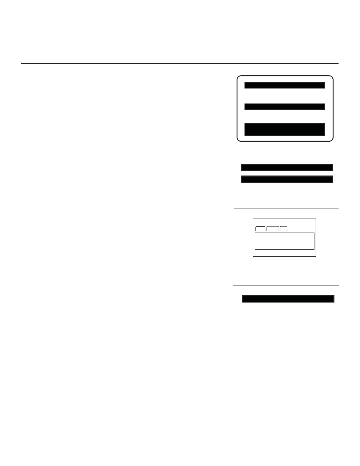
HOSPITAL PTC INSTALLER MENU
000 INSTALLER SEQ 000
UPN 000-000-000-000 FPGA E0F1
PTC V1.00.000 CPU V3.06.00
Typical TV Installer Menu
117 FACT DEFAULT 001
003 BAND/AFC 00X
Adjust the settings for these
Installer Menu items.
2. Set Up TV Features
(Channel, Picture, Audio, Lock, Time, Option, Digital Captions, etc.
DIGITAL 19-3
STEREO SAP
MONO
See TV Clonable Options list and TV Menus information.)
3. Run Auto Tuning (Channel Search)
a. (Search for all available channels.) Go to the Channel Menu, access
the Auto Tuning option, and follow the on-screen instructions.
b. In the Channel Menu, access the Channel Edit option to edit the
channel scan.
Custom Text Label “WXYZ” created in
2-5-4 + MENU (Add Channel Label) Mode.
• Add/delete channels per your system requirements.
Note: Physical channel numbers are used to identify virtual channels.
• Add familiar channel trademarks/logos like ABC, CBS, NBC, etc. to
the Channel-Time on-screen display. In the Channel Menu, select the
Channel Label option. Add identifiable labels (logos) for the end user
028 CH. OVERIDE 000
After Master TV Setup is completed,
set item 028 CH. OVERIDE to 000.
to readily know what common networks are available.
4. Transfer TV Setup to Internal TV Controller: 2-5-5 + MENU Mode
After the TV channel scan has been edited and channel label icons added, enter the Installer
Menu. Once in the Installer Menu, press 2-5-5 + MENU on the remote. This transfers the TV
setup to the internal controller box.
5. Add Custom Channel Labels for Analog Channels: 2-5-4 + MENU Mode
Enter the Installer Menu, and press 2-5-4 + MENU. Add your own custom text labels to channel
on-screen displays. Note: Digital channels often have a broadcaster generated label (see 2-5-4 +
MENU reference information). When you are finished, press MENU to exit 2-5-4 + MENU Mode.
WXYZ
6. Verify TV Setup
At this point, verify that the channel lineup, channel icons, and custom labels are correct.
Make sure the TV features are set per your requirements. Set item 028 CH. OVERIDE to 000
to lock the channel scan and restrict Setup Menu access. After the preceding has been completed, the Master TV Setup is ready to be copied to a Clone Programmer (see cloning information in this document).
206-4096
7
Page 8
Express Script Installer Menu Wizard
(LG3DDH TVs only)
The Express Script Installer Menu Wizard enables users to set up essential items for viewing the TV the
fi rst time it is turned on. The Express Script Installer Menu Wizard can also be activated from the Installer
Menu—set Installer Menu item 117 FACT DEFAULT to 001 to reinitiate the Express Script (see the “In-
staller Menu” section of this document for further information).
Note: If you plan to perform the Commercial Mode Setup using the procedure on page 7, via cloning,
or via the FTG (Free-To-Guest) Confi guration Application, be sure to exit the Express Script in order to
avoid setup confl icts that may cause the TV to malfunction.
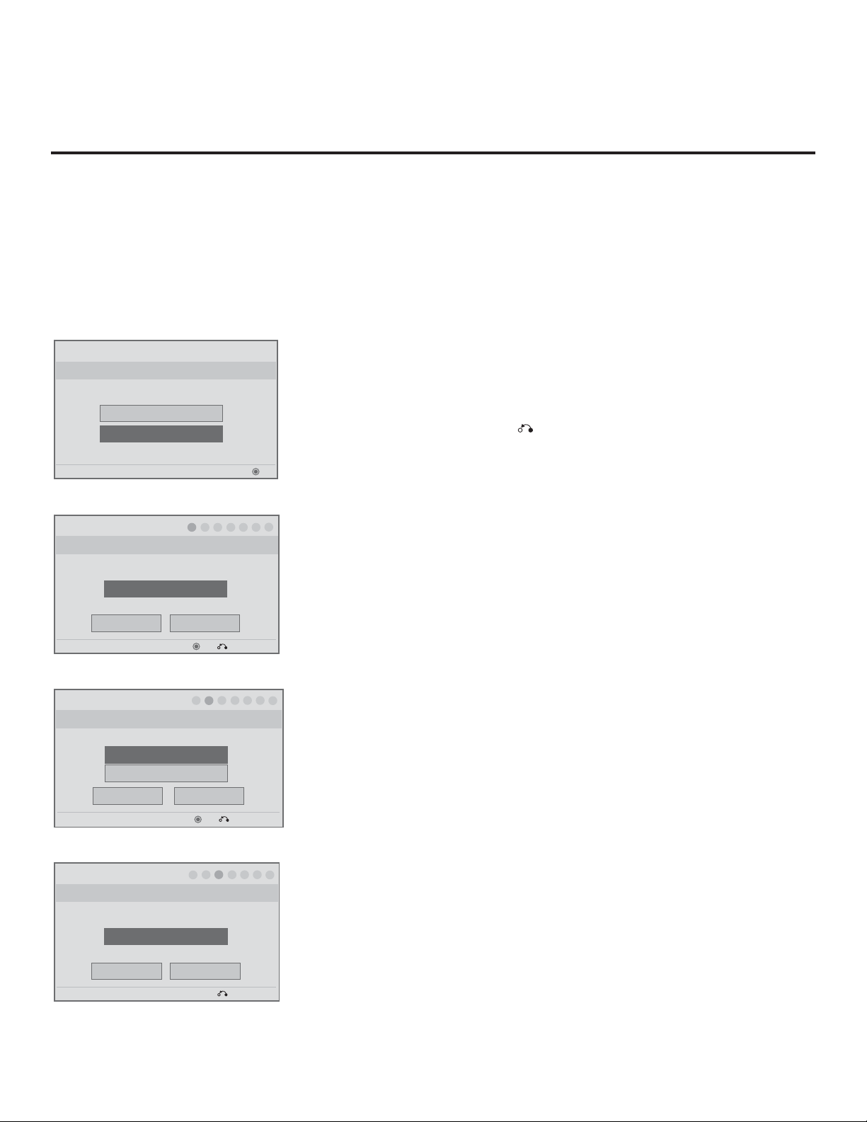
Installer Menu Wizard
Select Menu Mode
Which menu mode will you be using?
Express Script
Exit Express Script
PTC: V1.00.006 CPU: V01.17.00 FPGA: 20E7
Installer Menu Wizard
Step 1. Tuning Band
Which tuning band would you like to use?
►
Cable Standard
Exit Script
F
Back
PTC: V1.00.006 CPU: V01.17.00 FPGA: 20E7
Installer Menu Wizard
Step 2. Aux Input
Which inputs will you be using?
Customize Inputs.
Use default values.
Back
PTC: V1.00.006 CPU: V01.17.00 FPGA: 20E7
►
►
►
214 5 63
►
G
Next
OK Exit Express Script
►
1
►
►
2
Next
OK Exit Express Script
1. Use the Installer Remote Up/Down arrow keys to select/highlight
the desired Menu Mode. Then, press ENTER.
The remaining steps of this procedure describe the Express Script
Installer Menu Wizard; however, you can exit the Express Script at
any time using the RETURN key.
In addition, you can use the Back button, where available, to check
OK
►
►
►
7
previous settings, as necessary.
2. Use the Left/Right arrow keys to select the Tuning Band. When you
have made your selection, use the Up/Down/Left/Right arrow keys
to select Next, and press ENTER.
3. Use the Up/Down arrow keys to select/highlight the desired Aux
►
4 5 63
►
►
7
Input option.
To customize settings, select Customize Inputs, and press
ENTER. Aux Input options are displayed in a pop-up window. Use
the Up/Down/Left/Right arrow keys to select the input(s) you want
to enable or disable. When you are fi nished, press MENU to close
the pop-up window and continue.
To use default values, select Use default values. Then use the Up/
Down/Left/Right arrow keys to select Next, and press ENTER.
Installer Menu Wizard
1
►
3
►
►
2
Step 3. Pillow Speaker
Up/Down/Left/Right arrow keys
Which brand pillow speaker code will you be using?
►
Zenith code
Exit Script
F
Back
PTC: V1.00.006 CPU: V01.17.00 FPGA: 20E7
►
G
Next
OK Exit Express Script
8
►
4 5 6
►
►
7
4. Use the Left/Right arrow keys to select the appropriate Pillow
Speaker code. Then, use the Up/Down/Left/Right arrow keys to
select Next, and press ENTER.
(Continued on next page)
206-4096
Page 9
(Continued from previous page)
Express Script Installer Menu Wizard (Cont.)
(LG3DDH TVs only)
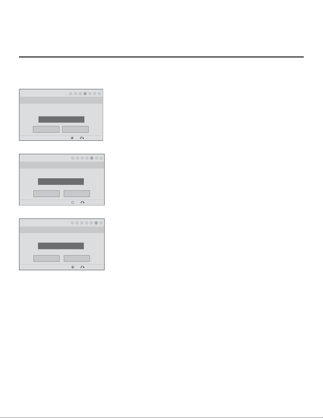
Installer Menu Wizard
1 2
►
►
Step 4. Channel Access
Do you want to allow direct access to channels not in
PTC: V1.00.006 CPU: V01.17.00 FPGA: 20E7
Installer Menu Wizard
the channel list?
►
Back
Yes
Next
1
OK
2
►
Step 5. Auto Search
Would you like to scan for available channels?
Excute Auto Search
1
Next
OK
►
►
2
Back
PTC: V1.00.006 CPU: V01.17.00 FPGA: 20E7
Installer Menu Wizard
Step 6. Channel Map Edit
Would you like to edit channel map and icons?
Edit channel map.
Back
PTC: V1.00.006 CPU: V01.17.00 FPGA: 20E7
Next
OK
4
►
3
►
Exit Express Script
►
►
4
3
Exit Express Script
►
3
4
Exit Express Script
5 6
►
►
►
7
5. Use the Left/Right arrow keys to select the appropriate Channel
Access option (yes or no). Then, use the Up/Down/Left/Right arrow
keys to select Next, and press ENTER.
►
►
►
6
7
5
6. Select/highlight Execute Auto Search, and press ENTER to start
the channel scan. The system will display the progress of the channel scan in a pop-up window. When the scan is complete, press any
key on the Installer Remote to close the pop-up window.
When the scan is complete, or to continue without running the
channel scan, use the Up/Down/Left/Right arrow keys to select
Next, and press ENTER.
►
►
►
7
5
6
7. Press ENTER, if desired, to edit Channel Map settings. Channel
Map options will be displayed in a pop-up window. Use the Up/
Down/Left/Right arrow keys to make any necessary edits. When
you are fi nished, press MENU to close the pop-up window.
Then, use the Up/Down/Left/Right arrow keys to select Next, and
press ENTER.
206-4096
For the fi nal step, the system will save your settings, transfer the setup
to the internal TV controller (similar to 2-5-5 + MENU Mode), and exit
the Installer Menu Wizard.
9
Page 10
Installer Overview
Operating Installer Menu
To set up the controls for the TV you will need to know how to enter the TV
Installer menu and make changes to the default values. If necessary, familiarize yourself with the TV Installer menu and how to make and save changes to the items in the menu.
LG Installer Remote
You will need an LG Installer Remote similar to the one shown to the right.
The Installer Remote must have a SOURCE button or its equivalent. The
remote shown for reference on this page has an INPUT button, which
serves the purpose of a SOURCE button.
The TV’s clonable features need to be set up. This is a critical step. If the
Master TV display panel’s clonable features like added channel icons or
channel labels are not done correctly, then the cloned TVs will all have
problems. Refer to the TV menus for other TV features: Picture, Audio,
Option, Closed captions, Lock (V-Chip), etc.
TLL-1100A Clone Programmer
The TLL-1100A is a very simple cloner to use. It can be set up to clone a
master TV setup and transfer it into a target TV. Cloning is possible using
MPI protocol. Be sure the Master TV is set up completely.
TV Link
Loader-Demo
TLL1100A
Ready
MODE
MENU
Cloning is only possible when the signal source is an
Analog channel, not a digital channel. Refer to TLL-1100A
instruction manual supplied with the cloner.
HOSPITAL PTC INSTALLER MENU
000 INSTALLER SEQ 000
UPN 000-000-000-000 FPGA E0F1
PTC V1.00.000 CPU V3.06.00
Typical Installer Menu
INPUT MODE
PO WER
INPUT
MULTI
EZ SOUND
EZ PIC
CC
EXIT
MENU
ENTER
SW AP
TVTV
DV D
VCR
INFO
RATIO
SAP
RECEIVE SEND
10
ENTER
TLL1100A
TIMER
VO L
MUTE
123
456
789
PA G E
CH
FLASH
0
BACK
206-4096
Page 11
INPUT MODE
PO WER
INPUT
MULTI
SW AP
EZ SOUND
EZ PIC
TVTV
DV D
VCR
INFO
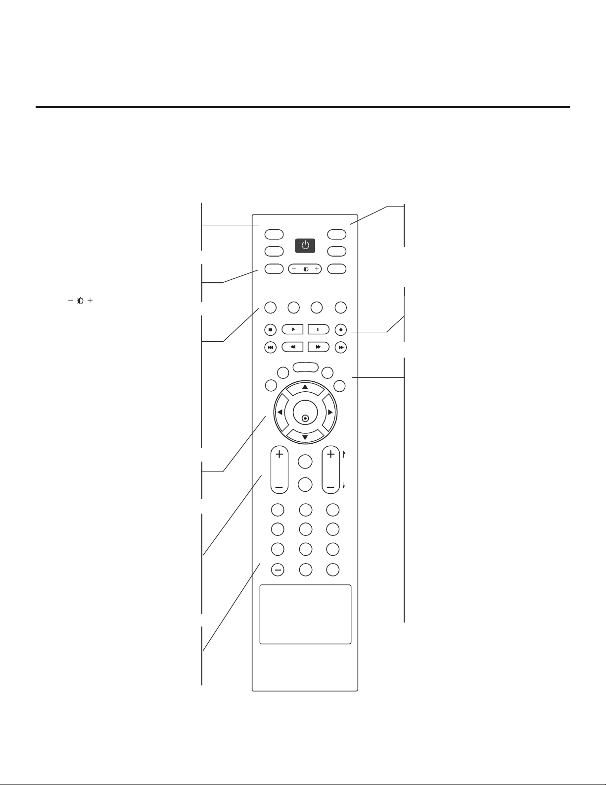
Typical Multi-brand Installer Remote Control
LG Multi-brand Installer Remote
Use the MODE button to select the TV and put the Installer
Remote into TV operating mode.
See next page for typical key functions in TV operating mode.
Follow the instructions provided in the “Installer Menu” section
of this document to configure the TV’s features.
CC
EXIT
VO L
123
456
789
MENU
ENTER
TIMER
MUTE
0
RATIO
CH
FLASH
SAP
PA G E
AA +
AA +
BACK
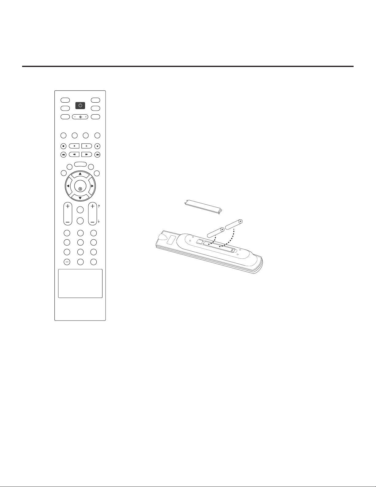
Installing Batteries in Installer Remote
• Remove the battery compartment cover on the back side by
pressing the arrow tab forward and lifting. Install batteries
matching correct polarity as shown (+ with + and - with -).
• Install two high-quality alkaline 1.5V AA batteries. Never mix
old or used batteries with new ones. Replace cover.
206-4096
11
Page 12
Installer Remote Control Typical Key Functions
To put the Installer Remote into TV operating mode, select TV with the MODE button.
Note:
The LG Installer Remote illustrated below and throughout this document shows typical remote control functions and
is provided for reference only. This Installer Remote may vary from the actual Installer Remote supplied with the TV.
TV INPUT/INPUT
Select available input sources.
POWER
Turns the TV or any other programmed
equipment On or Off, depending on mode.
MULTI
Selects RGB, HDMI,DVI, HDMI2 and
Component Input sources.
Adjusts picture brightness.
EZ PIC (For 22/26/32LG3DCH)
Selects the factory preset picture appropri-
ate for the viewing environment.
EZ SOUND (For 22/26/32LG3DCH)
Sets the appropriate sound for the pro-
gram’s content.
SWAP
Exchanges the main/sub images in Twin
picture mode.
INFO
During a TV program, will display program
information on top of the screen. Info fea-
ture is not functional for Aux sources.
THUMBSTICK Up/Down/Left/Right/
ENTER
Use to navigate on-screen menus / adjust
the system settings to your requirements.
VOLUME UP/DOWN
Increases/decreases the sound level.
TIMER
Sets the amount of time before the TV
automatically turns itself Off.
MUTE
Switches the sound on or off.
CHANNEL UP/DOWN/PAGE
Selects available channels found with EZ
Scan. Moves to next available page.
NUMBER Buttons (0 - 9) DASH
Use to enter a program number or channels.
Dash for multiple channels such as 9-1, 9-2,
etc.
FLASHBK
Returns to the previously viewed channel.
INPUT MODE
PO WER
INPUT
MULTI
EZ SOUND
EZ PIC
CC
EXIT
MENU
ENTER
TIMER
VO L
MUTE
123
456
789
0
SW AP
RATIO
CH
DV D
VCR
FLASH
BACK
TVTV
INFO
SAP
PA G E
MODE
Selects remote operating mode: TV, VCR,
or DVD. Select these other operating
modes for remote to operate external
devices.
VCR/DVD BUTTONS
Control some video cassette recorders or
DVD players. (“RECORD” is not functional
in DVD mode.) Set up for VCR recording:
Once, Regularly, Weekly, Off. (“RECORD”
button only).
EXIT
Clears all on-screen displays and returns
to TV viewing from any TV menu.
CC
Selects a closed caption option.
MENU
Displays the Main Menu on the screen.
Enters or exits a Panel Menu in the TV
Guide on-screen menu system.
RATIO
Adjusts the picture aspect ratio.
SAP
Selects MTS sound: Mono, Stereo, and
SAP in Analog mode.
Changes the audio language in DTV
mode.
SAP Notes
• SAP settings are retained with power off/
on for individual analog channels.
• If SAP is selected and no SAP is provided, sound will not be heard on channel.
• Each analog channel may have its own
SAP setting.
• Digital channels will reset to default
audio language with a power off/on.
12
206-4096
Page 13
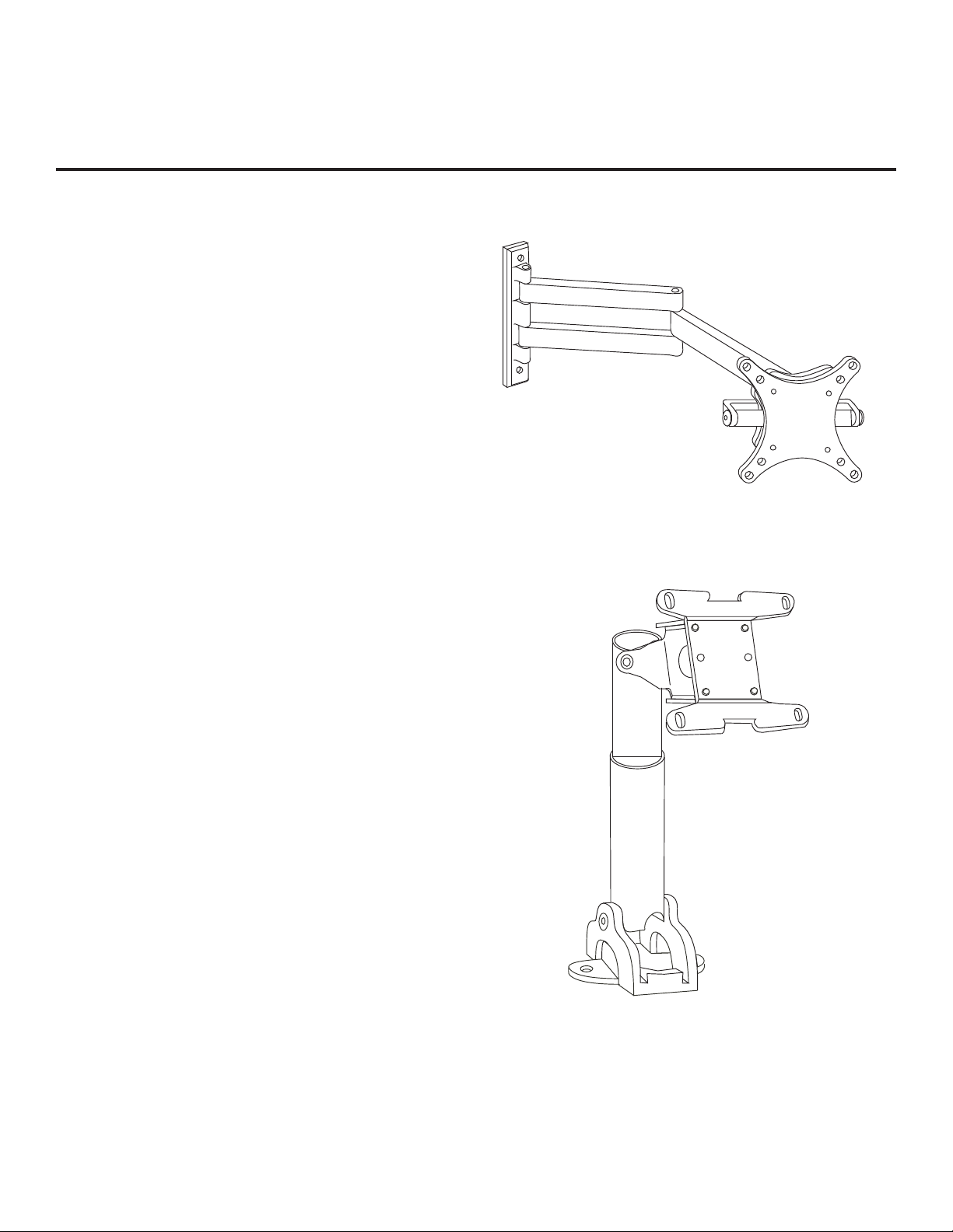
General Guidelines: Choosing a Location
for Installing a VESA Standard Mount
To the right are some examples of VESA
standard mounts. Since there are numerous
types of stands and mounts available, only
a few are shown here. Refer to the instructions provided with the TV stand that will be
used to mount the TV. Be sure the style of
stand selected is capable of supporting the
weight of the TV and is appropriate for the
application.
Wall Mounts
If the mount will be on a wall, a typical
wooden stud behind the wall board would be
the preferred choice for a location to attach
the wall mount. The wall mount location
chosen should be appropriate for drilling
holes and have available the required power
source as well as antenna/cable and any
other equipment leads as necessary.
VESA Standard TV Mounts
Typical Wall Stud Type Mount with
Swivel Bracket
Pedestal Mounts and Stands
A sturdy surface on a desk or other similar
flat table-like furniture would be the appropriate location for mounting a pedestal-style TV
stand.
Most stands are designed so that the wiring
is threaded through the stand itself or a loopthrough style clamp so that the wiring is
neatly bunched and not strung in such a way
as to create a potential hazard to the user.
(Some stands are portable and can be
moved from one location to another.) Be
sure all safety considerations are followed.
206-4096
Typical Pedestal Type Mount with
Swivel Bracket
13
Page 14
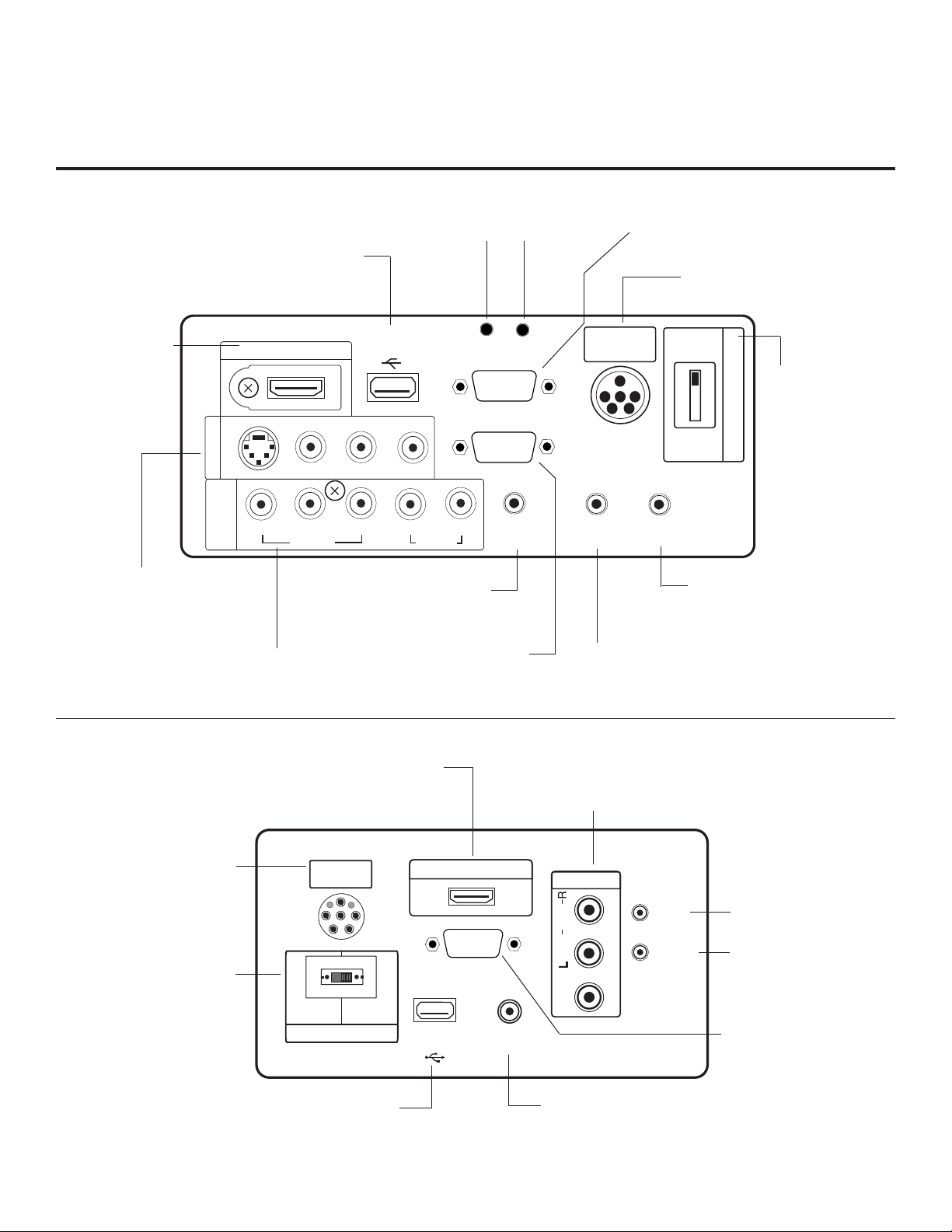
Rear Connections Panel
PILLOW
SPEAKER
HDMI/DVI IN
RS-232C IN
(SERVICE ONLY)
USB IN
SERViCE ONLY
REMOTE
CONTROL OUT
AV IN
VIDEO
AUDIO
MONO( )
NORMAL
SPEAKER
PILLOW
SPEAKER
SPEAKER SWITCH
RESET
UPDATE
DVI AUDIO IN
.....
....
......
..........
For further information, refer to the Owner’s Manual.
26/32LG3DCH
26/32LG3DDH
Restricted to service use only.
HDMI/DVI IN
Connect to output
jacks from HDMI/
DVI device.
AUDIO/VIDEO IN 1
Connect to output jacks
on audio/video or device.
(Except S-VIDEO:
26/32LG3DDH)
USB IN
HDMI/DVI IN
..........
R-AUDIO-L
AV IN 1
S-VIDEO
IN
COMPONENT
COMPONENT IN
Connect to output jacks
on component device.
PB
Y
VIDEO
Audio connection for RGB
UPDATE
Not functional.
USB IN
SERVICE ONLY
UPDATE
......
(MONO)
VIDEO
P
AUDIO IN (RGB / DVI)
L
R
or DVI device.
Connection for RGB
R
AUDIO
RGB IN (PC)
hookup from PC
RESET
Not functional.
RS-232C IN
SERVICE ONLY
.....
....
RGB IN (PC)
.....
.....
.....
AUDIO IN
(RGB / DVI)
RESET
CONTROL OUT
RS-232C IN
Provided for updating TV software.
PILLOW SPEAKER INPUT
Connect pillow speaker here.
PILLOW
SPEAKER
REMOTE
REMOTE CONTROL OUT
IR output for controlling an
auxiliary device.
NORMAL
SPEAKER
PILLOW
SPEAKER
SPEAKER OUT
ȍ
8
SPEAKER OUT (8-OHM)
Connect to 8 ohm external
speaker input.
SPEAKER SWITCH
Set to NORMAL
SPEAKER to hear TV
speakers sound. Set
SPEAKER SWITCH
to PILLOW SPEAKER
to hear pillow speaker
sound and have TV
controllable with pillow
speaker.
22LG3DCH
22LG3DDH
PILLOW SPEAKER INPUT
Connect pillow speaker here.
SPEAKER SWITCH
Set to NORMAL SPEAKER
to hear TV speakers sound.
Set to PILLOW SPEAKER to
hear pillow speaker sound
and have TV controllable
with pillow speaker.
14
HDMI/DVI IN PORT
Connect to output jacks
from HDMI / DVI device.
USB IN
Restricted to service
use only.
AUDIO/VIDEO IN
Connect to output jacks on
audio/video or device.
RESET
Not functional.
UPDATE
Not functional.
RS-232C IN
Provided for updating
TV software.
REMOTE CONTROL OUT
IR output for controlling an
auxiliary device.
206-4096
Page 15
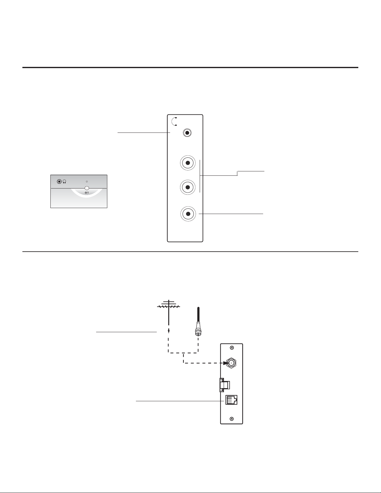
Side Connections Panel
Side Connections Panel / RF Antenna Connection
Headphone Output
Connect headphone to
this port.
(Headphone Output
for 22LG3DCH and
22LG3DDH)
RF Antenna Connection
H/P
L/MONO-AUDIO-R
VIDEO
AV IN 2
A/V 2 Input
L/MONO-AUDIO-R IN
Connect to audio output
jacks from external device.
For only mono audio output,
connect to Left audio input.
VIDEO IN
Connect to video output
port on external device.
206-4096
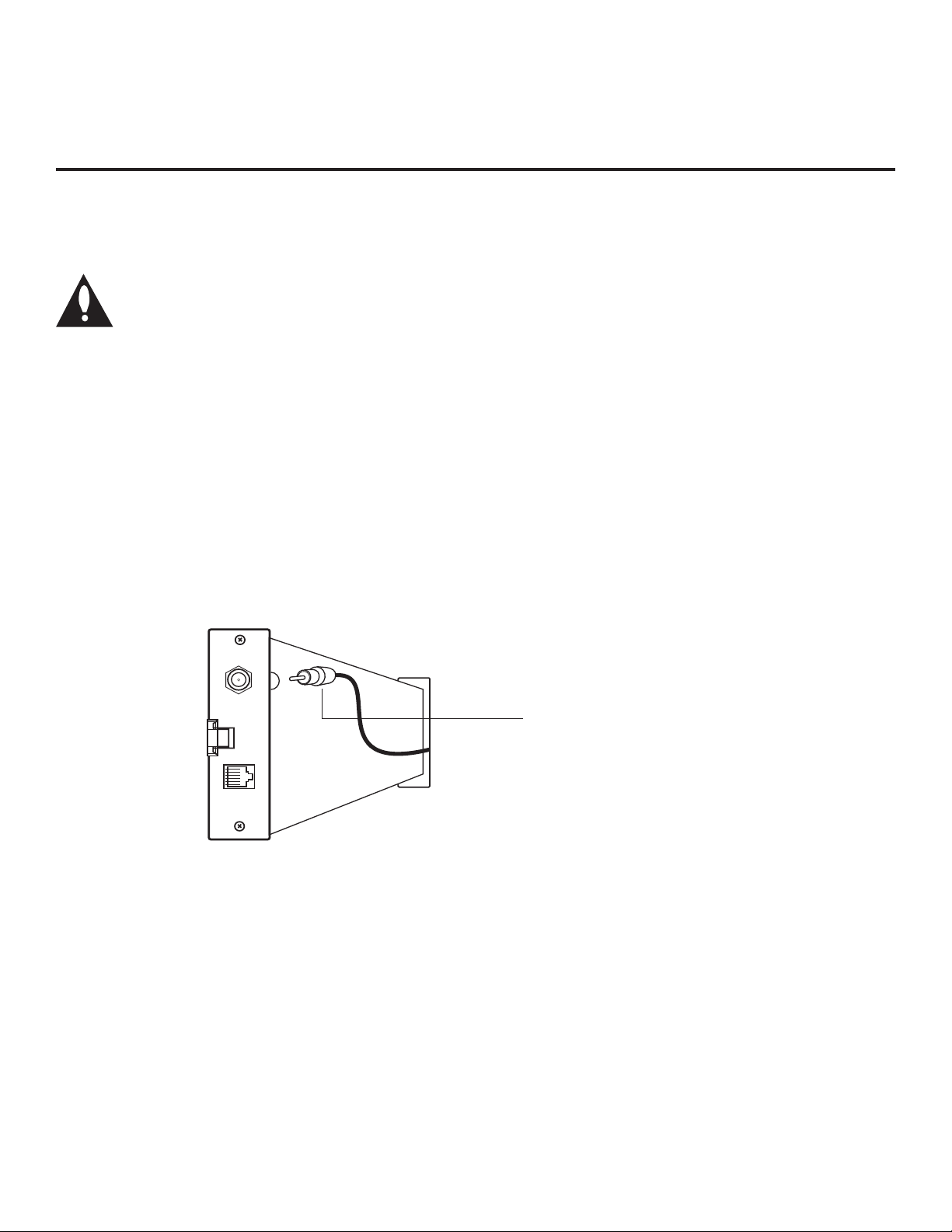
RF ANTENNA
Connect to
Antenna/Cable
Input on MPI card.
Connect external MPI
control devices (i.e., Cloner,
PPV provider, etc.).
MPI PORT
Antenna
or CATV
ANTENNA IN
MP I
15
Page 16
MPI Card Slot
The MPI card is equipped with an RF jack for antenna/cable signal source connection.
The slot is also available for installing a PPV (Pay-Per-View) card.
Note: (LG3DDH TVs only) Turn the TV On. If the Express Script Installer Menu
Wizard is present on the display (e.g., this is the first time the TV has been turned
On), exit the Express Script before inserting the PPV card.
MPI Card Removal / PPV Card Installation
1. Remove the two MPI card retainer screws.
2. Pull out the current MPI card far enough so that the RF cable can be detached from the old card.
3. Detach the RF cable.
4. Place the new PPV card into the slot and slide it in far enough to reconnect the RF cable.
5. Reconnect the RF cable.
6. Insert the card all the way into the slot making sure it is fully seated into the back plane connector.
7. Replace the two card retainer screws.
ANTENNA
/CABLE
MPI
DC IN
MPI
Card Slot
RF CABLE
RF cable needs to be
disconnected to remove
current card
.
16
206-4096
Page 17
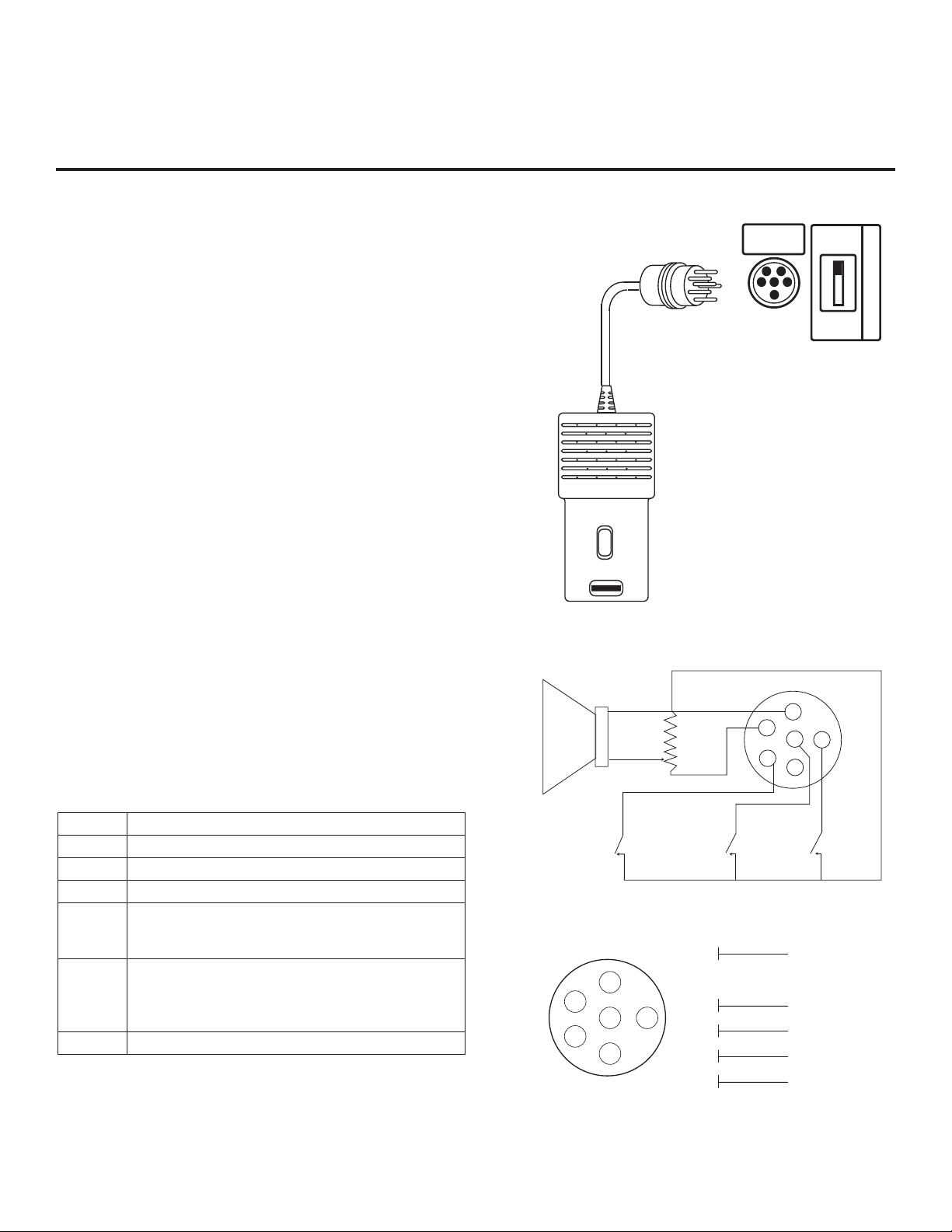
Pillow Speaker Setup
Set up pillow speaker after Commercial Mode Setup and Cloning procedures are complete.
Connect a Pillow Speaker to the LCD TV/Monitor
1. Connect the Pillow Speaker to the output jack on the
back of the TV.
2. Either:
• Slide the control switch to PILLOW SPEAKER on the
rear panel of the TV to control TV and hear audio on
pillow speaker.
• For TV speakers sound with pillow speaker control,
set the control switch to NORMAL SPEAKER.
Use a pillow speaker that is a UL recognized pendant
control bearing the warning: “Risk of fi re if used in oxygen
enriched atmosphere. Keep pendant control away from
oxygen equipment.”
Controlling the TV with Serial Data
The TV is capable of being controlled by a single-wire,
serial data signal. This is an LG patented technology and
is being implemented by certain brands of “smart” pillow
speakers.
Controlling the TV with Mechanical Switches
Pin 4 (common) is momentarily connected to pin 1, 3, or 6
via push-action switches to control Power On/Off and
Channel Up/Down. These pins are at +13 volts DC (when
measured from pin 4) with the switches open. Current
draw is 8 mA when a switch is closed. (This operation is
identical to previous models using the 5-wire interface,
except that only +7 volts DC was supplied and current
draw was only 2.5 mA.)
Pin No. Description
1 External TV On/Off switch.
2 (Not used)
3 External Channel Up switch or Data in.
4 Common connection for control, data, and audio
output. Impedance to earth ground is a 10-meg
resistor in parallel with a 1100 pf capacitor.
5 Isolated audio output. Nominal 14 ohm source
impedance with short circuit protection. Intended
for a pillow speaker with a low-impedance pad-type
volume control.
6 External Channel Down switch.
SPKR
TV
VOLUME CONTROL
TV
ON/OFF
4
5
6
1
2
PILLOW
SPEAKER
5
1
CHAN
DOWN
1
2
3
3
4
5
6
NORMAL
SPEAKER
PILLOW
SPEAKER
4
3
6
2
(MALE
PLUG)
CHAN
UP
TV ON/OFF
OPEN
CHAN UP/DATA IN
COMMON
AUDIO OUT
CHAN DOWN
SPEAKER SWITCH
206-4096
17
Page 18

Basic TV Features Overview
On-screen menus allow the Installer to set up the basic TV features.
Note that your TV's OSD (On-screen Display) may differ from that shown in this manual.
CHANNEL
Auto Tuning
Manual Tuning
Channel Edit
Channel Label
PICTURE
Aspect Ratio : 16:9
Picture Mode : Vivid
·Contrast
·Brightness
·Sharpness
·Color
·Tint
Backlight
·
Move
Enter
Move
Enter
100
100
50
50
50
0
CHANNEL
TIME
PICTURE
OPTION
AUDIO
LOCK
AUDIO
Auto Volume : Off
Clear Voice II : On
·Level
Balance :
Sound Mode : Standard
·Infinite Sound :Off
·Bass
Treble
·
LOCK
Lock System : Off
Set Password
Block Channel
Movie Rating
TV Rating-Children
TV Rating-General
Downloadable Rating
Input Block
OPTION
Menu Language : English
Audio Language : English
Caption : Off
Set ID : 1
Demo Mode : Off
TIME
Clock : - - - -, - - - - , - - : - - - -
Off Time : Off
On Time : Off
Sleep Timer : Off
Move
0
0
50
50
Move
Move
Move
Enter
Enter
Enter
Enter
18
206-4096
Page 19

Channel Menu
CHANNEL
PICTURE
AUDIO
TIME
OPTION
LOCK
CHANNEL
Enter
Move
Auto Tuning
Manual Tuning
Channel Edit
Channel Label
The Channel menu contains the channel search and channel scanning setup options.
Auto Tuning: Searches for analog and digital channels.
Manual Tuning: Gives the Installer the option to manu-
ally add channels to channels list in TV memory. Shows
signal strength for selected channel.
Channel Edit: Allows Installer to add/delete channels in
channel memory.
Channel Label: Adds an identifying logo to channel-time
OSD.
Channel Menu Navigation
Typical Menu Operation
Auto Tuning (Channel Search)
1. Press MENU on the Installer Remote.
2. Select the Channel menu option, and press
ENTER.
3. Use the Up/Down/Left/Right arrow keys to select the
Auto Tuning option.
4. Press ENTER.
5. Press ENTER again to start the channel search.
6. Press MENU to remove the Channel menu from the
screen.
206-4096
19
Page 20

Picture Menu
CHANNEL
PICTURE
AUDIO
TIME
OPTION
LOCK
PICTURE
Enter
Move
Aspect Ratio : 16:9
Picture Mode : Vivid
·
Backlight
·
Contrast
·
Brightness
·
Sharpness
·
Color
·
Tint
Advanced Control
Picture Reset
100
100
50
50
50
0
The Picture menu settings control the appearance on the TV picture.
Aspect Ratio: Sets the picture proportion.
Picture Mode: Selects factory preset picture options.
Also allows the Installer to specify custom picture setups.
(Additional menu options accessible
with Down arrow.)
20
Picture Menu Navigation
Typical Menu Operation
Picture Mode
1. Press MENU on the Installer Remote.
2. Select the Picture menu option, and press
ENTER.
3. Use the Up/Down/Left/Right arrow keys to select the
Picture Mode option.
4. Press ENTER.
5. Select from the preset picture mode options, or make
custom picture appearance settings.
6. Press MENU to remove the Picture menu from the
screen.
206-4096
Page 21

The Audio menu configures the TV sound options.
Audio Menu
CHANNEL
TIME
AUDIO
Auto Volume : Off
Clear Voice II : On
Balance :
Sound Mode : Standard
Level
·
Infinite Sound :Off
·
Treble
·
Bass
·
Reset
TV Speaker: On/Off
PICTURE
OPTION
0
0
50
50
Move
AUDIO
LOCK
Enter
(Additional menu options accessible
with Down arrow.)
Notes:
• 22/26/32LG3DCH: Auto Volume is disabled if the Pil-
low Speaker switch is set to “Pillow Speaker” and “TV
Speaker” is not selected as an audio source.
• 22/26/32LG3DDH: Audio Menu is disabled if the Pillow
Speaker switch is set to “Pillow’ Speaker” and “TV
Speaker” is not selected as an audio source.
Enables and disables Auto Volume (22/26/32LG3DCH) /
Audio Menu (22/26/32LG3DDH) option. See also Notes
below.
Enables and disables the Clear Voice II option.
(22/26/32LG3DCH: Clear Voice)
Balance: Gives the Installer the option to set the sound
output more to the Left or to the Right speaker.
Sound Mode: Selects preset optimum audio output
based on program content. The Installer can also make
custom sound settings.
Audio Menu Navigation
Typical Menu Operation
Sound Mode
1. Press MENU on the Installer Remote.
2. Select the Audio menu option, and press ENTER.
3. Use the Up/Down/Left/Right arrow keys to select the
Sound Mode option.
4. Press ENTER.
5. Select from the preset sound output options, or make
custom sound settings.
6. Press MENU to remove the Audio menu from the
screen.
206-4096
21
Page 22

Time Menu
The Time menu configures the TV clock options.
CHANNEL
TIME
TIME
Clock : - - - -, - - - - , - - : - - - -
Off Time : Off
On Time : Off
Sleep Timer : Off
PICTURE
OPTION
Move
AUDIO
LOCK
Enter
Clock: Set the internal clock on the TV automatically or
manually.
Off Time: Sets a time at which the TV will automatically
turn Off each day.
On Time: Sets a time at which the TV will automatically
turn On each day.
Sleep Timer: Sets a time at which the TV will turn itself
Off, once.
22
Time Menu Navigation
Typical Menu Operation
Sleep Timer
1. Press MENU on the Installer Remote.
2. Select the Time menu option, and press ENTER.
3. Use the Up/Down/Left/Right arrow keys to select the
Sleep Timer option.
4. Press ENTER.
5. Select a Sleep Timer TV Turn Off time.
6. Press MENU to remove the Time menu from the
screen.
206-4096
Page 23

The Option menu can be used to configure digital captions for the end user.
CHANNEL
PICTURE
AUDIO
TIME
OPTION
LOCK
OPTION
Enter
Move
Menu Language : English
Audio Language : English
Caption : Off
Set ID : 1
Demo Mode : Off
OPTION
Enter
Move
Language
: English
Caption : Off
or
Menu / Audio Language: Selects English, Spanish, or
French.
Option Menu
or
Caption: Enters the Captions menu. Allows the Installer
to specify which analog or digital captions will appear.
The Installer can customize the appearance of the digital captions.
Demo Mode: Displays a slide show to explain the
features of this TV.
Option Menu Navigation
Typical Menu Operation
Caption (Turns captions on/off and enters submenus)
1. Press MENU on the Installer Remote.
2. Select the Option menu option, and press ENTER.
3. Use the Up/Down/Left/Right arrow keys to select the
Caption option.
4. Press ENTER.
5. Set up Caption menu and Digital Captions submenus
options.
6. Press MENU to remove the Option menu from the
screen.
206-4096
23
Page 24

Lock Menu
The Lock menu can be used to set up V-Chip (Parental Control).
CHANNEL
TIME
LOCK
Lock System : Off
Set Password
Block Channel
Movie Rating
TV Rating-Children
TV Rating-General
Downloadable Rating
Input Block
PICTURE
OPTION
Move
AUDIO
LOCK
Enter
Notes:
• 22/26/32LG3DCH: The Installer can enter 7-7-7-7 to
access the Lock menu if it is active and the password
is not available.
• 22/26/32LG3DDH: The Installer can enter 0-3-2-5 to
access the Lock menu if it is active and the password
is not available.
Lock System: Enables and disables the parental lock.
Set Password: Sets the V-Chip password.
Block Channel: Allows the Installer to block individual
channels.
The remaining Lock menu options set up individual
V-Chip controls for programming that can appear.
If provided on program, additional blocks can be set to
restrict programming that can appear.
Lock Menu Navigation
Typical Menu Operation
Lock System
1. Press MENU on the Installer Remote.
2. Select the Lock menu option, and press ENTER.
3. Use the Up/Down/Left/Right arrow keys to select the
Lock System option.
4. Press ENTER.
5. Set the Lock System to be enabled or disabled. Set
up V-Chip blocks for the available Parental Control
options.
6. Press MENU to remove the Lock menu from the
screen.
24
206-4096
Page 25

Channel Banks Note: Disable all Aux sources in the Installer Menu that will not be made available to the end user.
Channel Banks Overview
Channel banks enable the institution administrator to control access to patient
in-room TV programming. A channel bank can be enabled for a patient for a
pre-determined fee. For Banks 1-2 and 3, the institution can create programming levels. Each level would offer a custom channel lineup. Top tier would
be the most programming (premium, etc.), 2nd tier = lesser programming, 3rd
tier = basic programming, etc. Channel Bank 4 would display the “Inactive TV
Call Attendant” message when the TV is turned On. The administrator could
activate Banks 1-2 or 3 depending on the programming tier selected by the
patient. When the patient leaves the hospital, the administrator can then
select Bank 4 to reinstate the “Inactive TV” message.
Channel Banks Overview
CHANNEL PREVIEW - BANK 1
CH 011-001 NORMAL-ADDED
CC -> VCHIP Menu Ch. Preview -> Exit
Enter -> Change
Channels Available Charts
All channels found in the channel search are included in all channel banks.
The default is for all channels to be active in Channel Banks 1-2-3 and 4.
Create channel banks charts similar to the examples on the following pages.
On the channel bank chart, show the status for each channel in all channel
banks. This then becomes the patient entertainment programming offerings
plan.
Channel Banks Setup
Operating the Channel Banks menu.
Note: Channel banks can only be set up after the 2-5-5 + MENU procedure
has been completed. See remote key functions for Channel Banks menu on
the following page.
Channel Status Options Available for Channel Banks
In the Ch Preview-Channel Banks menu, use the Channel Up/Down arrows
to go to a channel and the Left/Right arrows to select the channel status. See
channel status chart.
Inactive TV Setup
Go to Channel Bank 4. Select NORMAL DELETE for all channels. When the
TV is powered on by the patient, the “Inactive TV Call Attendant” message
will appear on the screen and after a few moments the TV will turn itself Off.
With the Installer Remote, the administrator can activate Banks 1, 2, or 3
depending on the entertainment programming tier selected by the patient.
When the patient leaves the hospital, the administrator can then select Bank
4 to reinstate the “Inactive TV” message.
Channel Banks Setup Menu
MUTE
BANK
SAP
VOL
TIMER
ADJ
PREVIEW
INFO
CH
OK
CH
MENU
ADJ
ADJ
BED1
CH
POWER
GUIDE
CC
VOL
FLASHBK
ALARM
ADJ
BED2
Note: The default setting for Aux sources is to be active in the Installer Menu. The
Aux sources will appear between the highest analog and lowest digital channel number in the channel scan with Channel Up/Down. If the Aux sources will not be used,
it is advisable to set them to 000 (Off) before running 2-5-5 + MENU. After running
2-5-5 + MENU, the only way to turn the Aux sources off so they will not appear in
the channel scan, is to go to the Channel Banks menus and select Normal Delete.
Refer to Installer Menu items: 034, 035, 038, 039 and 087.
206-4096
3140OSKZ003AR6
Use to access Ch Preview Menu.
25
Page 26

Channel Banks Setup Installer Remote Control Key Functions
After running 2-5-5 + MENU, select a channel bank with the INPUT/
SOURCE or BANK button. After the desired bank is selected, press
CH PREVIEW to display the Channel Banks editing menu.
CHANNEL PREVIEW - BANK 1
CH 011-001 NORMAL-ADDED
CC -> VCHIP Menu Ch. Preview -> Exit
Enter -> Change
Channel Banks Setup Menu
MUTE
BANK
SAP
VOL
CH
PREVIEW
INFO
CH
OK
CH
POWER
GUIDE
CC
VOL
Shows currently selected channel bank.
Shows currently selected channel.
Shows channel status in selected bank.
In the Channel Banks menu, use Left/Right arrows to select:
• Normal-Added: Channel will appear in channel scan.
• Normal-Deleted
: Channel will not appear in channel scan.
• Blank-Added: Channel will appear in all channel banks, video will
be black, no picture.
• Blank-Deleted : Channel will be blanked in all channel banks.
Bank
Selects channel banks 1-2-3-4.
Ch Preview
Selects Channel Banks setup menu.
Exits menu.
Channel Up
Selects next higher channel number.
OK (Enter)
Tunes in deleted channels in scan.
Channel Down
Selects next lower channel number.
26
FLASHBK
MENU
TIMER
ADJ
3140OSKZ003AR6
BED1
ADJ
ADJ
ALARM
ADJ
BED2
Typical Installer Remote
Up/Down Left/Right ADJ Arrows:
• Up/Down: Tune to added channels
in menu.
• Left/Right: Choose menu options.
Note: CC displays the V-Chip menu.
206-4096
Page 27

Channel Banks Setup
Use the Channel Banks to format the channel lineup programming package options for the end user.
Each channel bank is capable of storing broadcast digital and analog channels.
Example: Typical Channel Banks After Auto Tuning
B
Purpose Channel Number
A
N
K
1 A A A A AAAAAAA AAAA
2 A A A A AAAAAAA AAAA
3 A A A A AAAAAAA AAAA
4 A A A A AAAAAAA AAAA
A = Active (channel was found during Auto Tuning)
Example: Typical Channel Banks After Auto Tuning and Customization with Add/Del/Blnk Options
12345678910111213141516171819202122232425
B
Purpose Channel Number
A
N
K
1 BCA AAAA DDDDDDD DDDD
2 BCA AAAA ADADAAADDDD
3 BCA AAAA ADADAAAADAA
4 BCA AAAA AAAAAAA AAAA
A = Active (channel was found during Auto Tuning)
D = Delete (channel was deleted using the Add/Del channel option)
BC = Blanked Channel (channel was blanked using the Blank channel option)
Adding / Deleting / Blanking Channels
It is best to do ADD / DEL customizing before doing
12345678910111213141516171819202122232425
Note: Installer Menu item 028 CH. OVERIDE must be set
to 001 to allow access to the channel scan.
“BLANK.” Auto Tuning (channel search) enters the same
channel numbers in channel banks 1, 2, 3 and 4. Auto
Tuning removes any channels previously customized with
ADD / DEL / BLANK. The channels found in the channel
search on your antenna / cable will be included, and any
channels previously found but not currently available will
not be included. ADD and DEL (not BLANK) can be used
independently for channel banks 1, 2, 3 and 4. (If a channel is not found in the channel search, it can be added see
the Channel Menu Manual Tuning option.)
Note: A channel blanked, is blanked in all channel banks.
Selecting Deleted Channels
Channel allocations in tuning bands:
• Broadcast and Broadcast Digital: 2 - 69
• CABLE - CATV, HRC or ICC: 1 - 125
Inactive TV Setup for Channel Bank 4
To create an inactive TV display on Channel Bank 4,
select Normal Delete for every channel in Bank 4. When
Bank 4 is selected with the BANK button on the Installer
Remote, the “Inactive TV Call Attendant” message will be
shown on the TV screen. The TV will turn itself Off after-
ward. This will prompt the patient to arrange for an avail-
able programming package on Banks 1, 2 or 3.
To tune to a Normal Delete channel, either:
• Select a channel bank where the channel is added.
• Direct enter the channel number; then go to the bank
where the channel is set as “Normal Delete” and reconfigure the channel status.
206-4096
27
Page 28

Channel Banks Worksheet
Use this worksheet to plan your program packages. (Photocopy additional worksheets as needed.)
B
Purpose Channel Number
A
N
K
1
2
3
4
B
Purpose Channel Number
A
N
K
1
2
3
4
12345678910111213141516171819202122232425
26 27 28 29 30 31 32 33 34 35 36 37 38 39 40 41 42 43 44 45 46 47 48 49 50
B
Purpose Channel Number
A
N
K
1
2
3
4
B
Purpose Channel Number
A
N
K
1
2
3
4
B
Purpose Channel Number
A
N
K
1
2
3
4
51 52 53 54 55 56 57 58 59 60 61 62 63 64 65 66 67 68 69 70 71 72 73 74 75
76 77 78 79 80 81 82 83 84 85 86 87 88 89 90 91 92 93 94 95 96 97 98 99 100
101 102 103 104 105 106 107 108 109 110 111 112 113 114 115 116 117 118 119 120 121 122 123 124 125
28
Date _____________ Installer _____________________________________ Page ___ of ____
Location ______________________________________________________________________
206-4096
Page 29

Upgrading TV Software with USB Memory Card
Upgrade TV Software
USB Download Menu
Upgrade TV Software
Upgrade PTC Software
Teach To TV
Exit
Select a type of sofware to be downloaded:
Upgrade TV Software
Upgrade PTC Software
Teach To TV
Teach To TV
The following software files are found in the memory card.
Select the file you want to download to this TV.
Or, press EXIT to cancel the upgrade.
Software File List in USB Memory
32LG30_UA_ 128.TLL
32LG30_UA_ 126.TLL
Teach To TV
xxLG3DDH-UA00001.TLL
xxLG3DDH-UA00010.TLL
xxLG3DDH-UA00013.TLL
Previous
.....
HDMI/DVI IN
AV IN 1
S-VIDEO
IN
Y
COMPONENT
..........
R-AUDIO-L
PB
VIDEO
USB IN
SERVICE ONLY
......
(MONO)
P
R
VIDEO
L
UPDATE
AUDIO
R
RS-232C IN
SERVICE ONLY
.....
....
RGB IN (PC)
.....
.....
.....
AUDIO IN
(RGB / DVI)
RESET
REMOTE
CONTROL OUT
Typical Layout
Upgrading TV Software
1.
Plug the USB memory card into the USB
In port on the TV.
2.
The Upgrade TV Software (LG3DCH) /
USB Download Menu (LG3DDH) menu
should appear; if not, press MENU.
3. Use the Up/Down arrow keys to navigate
through the upgrades. Select/highlight
the upgrade you want to install, and press
ENTER.
Copying progress will be shown. When upgrading is complete, the TV will turn Off.
PILLOW
SPEAKER
NORMAL
SPEAKER
PILLOW
SPEAKER
SPEAKER OUT
ȍ
8
For 22/26/32LG3DCH
For 22/26/32LG3DDH
SPEAKER SWITCH
On USB Memory Card
Ensure that memory card has been formatted
with FAT format.
For 22/26/32LG3DCH
For 22/26/32LG3DDH
Optional: Edit / Change Filename
If necessary, the filename can be edited or changed.
Notes
• Do not remove the TV power cord or the USB memory card while
Learning, as doing so may harm the USB memory card.
• Do not remove the TV power cord or the USB memory card while
Teaching, as doing so may cause the TV to malfunction.
• You may edit the fi lename; however, a fi le with edited contents will not
be recognized.
• Since clock data is copied into the USB memory card as numeric data,
the time difference between Teaching and Learning is not automatically
adjusted. Either set the clock manually, or use the Auto Clock setting
on the TV Main Menu.
206-4096
For 22/26/32LG3DCH
Learn From TV
Choose the name of the image file:
32LG3DC_UA_ a a c c c .TLL
For 22/26/32LG3DDH
Learn From TV
Select the file name and press OK to start
xxLG3DDH-UA00001.TLL
Previous
29
Page 30

Master TV Profile Setup Learning / Teaching with USB Memory Card
Upgrade TV Software
Select a type of sofware to be downloaded:
Upgrade TV Software
Upgrade PTC Software
Teach T o TV
Learn From TV
USB Download Menu
Upgrade TV Software
Upgrade PTC Software
Teach T o TV
Learn From TV
Exit
Learn From TV
Learning current profile from master TV:
20%
Do not unplug until restart automatically
Learn From TV
20%
Upgrading...
Do not unplug!
!
Teach Current Profile
Teaching the selected profile to the TV:
20%
Do not unplug until restart automatically!
Teach To TV
20%
Upgrading...
Do not unplug!
!
On Master TV, Create Profile and Learn
For 22/26/32LG3DCH
For 22/26/32LG3DCH
1. Set up all Master TV features on the
menus, and do a channel search. Add
channel and Aux labels, etc. (See setup
procedure on page 7 or pages 8 – 9,
as applicable.) Tune in an analog channel.
2. Plug the USB memory card into the
USB In port on the Master TV.
3. Press MENU to open the Main Menu.
For 22/26/32LG3DDH
For 22/26/32LG3DDH
4. Press the Left arrow key once to highlight
the Option icon on left side of menu.
5. Press the number “7” key a total of seven
times.
6. Key in the password used to enter the
Installer Menu (see “Installer Menu”
section).
7. Use the Up/Down arrow keys to highlight Learn From TV, and press ENTER.
8. To identify the profi le from others, you can change the last fi ve digits. Key in a custom
fi lename, and then press ENTER.
The Learning status will be shown on the progress bar. As soon as current profi le learning is
complete, a message will appear on screen indicating that the Learning process is done.
9. Remove the USB memory card.
On Target TV, Teach Master TV Profile
1. Plug the USB memory card with the Master TV Profi le setup into the Target TV
USB In port.
2. Press MENU to open the Main Menu.
3. Press the Left arrow key once to highlight the Option icon on left side of menu.
4. Press the number “7” key a total of seven times.
5. Using the Up/Down arrow keys to select Teach New Profi le, and press ENTER.
6. Use Up/Down arrow keys to navigate through profi les. Select/highlight the profi le
that you want to install, and press ENTER.
Teaching progress will be shown on the progress bar. As soon as teaching is done,
a message will appear indicating that the Teaching process has been completed.
7. When Teaching is done, remove the USB memory card, and unplug the TV power
cord.
8. Reconnect the TV power cord, and turn ON the TV. The Master Setup should be
resident on the TV.
30
For 22/26/32LG3DCH
For 22/26/32LG3DDH
206-4096
Page 31

TLL-1100A Clone Connections / Learning and Teaching Setups
Connections for the TLL-1100A Clone Programmer to Learn the Master TV Setup
On Master TV
Set up all Master TV features on the
menus, and do a channel search. Add
channel and Aux labels, etc. (See
setup procedure on page 7 or pages
8 – 9, as applicable.) Insert the MPI
cable into the TV MPI port.
On TLL-1100A
1. Turn ON the TLL-1100A.
2. Use the MODE button to select
Clone Mode.
3. Use the Left/Right arrow to select
the CBank (1 to 8) in which to store
the Master Setup.
4. Plug the other end of the MPI cable
into the MPI port on the bottom of
the TLL.
5. With the Installer Remote, select
item 1 on the TLL Menu.
6. Press ENTER to transfer the Master
Setup into CBankX on the TLL. The
TLL will copy the Master Setup.
7. When Learning is done, disconnect
the MPI cable from the Master TV.
8. Reconnect the TV power cord, and
turn ON the TV. The Master Setup
should be resident on the TV.
CLONE SELECTION MENU
Selected Bank: CBankX Saved
(1) LEARN FROM TV
(2) TEACH TO TV
(3) SET CLONE CLOCK FROM TV
(4) SET TV CLOCK FROM CLONE
(5) DISPLAY TV SETUP
(6) DISPLAY CLONE SETUP
CLONE CLOCK = 00:00
TV CLOCK = 00:00
THE CLONE IS VERSION V2.2.2
-To change menu items, press
channel keys or digits.
-To execute item, press ENTER.
TV Link
Loader-Demo
TLL1100A
Ready
MODE
MENU
ENTER
RECEIVE SEND
TLL1100A
MPI Learning Setup
Antenna
(or CATV)
MPI Teaching Setup
Antenna
(or CATV)
TV Link
Loader-Demo
TLL1100A
Ready
MODE
MENU
ENTER
RECEIVE SEND
TLL1100A
CLONE SELECTION MENU
Selected Bank: CBankX Saved
(1) LEARN FROM TV
(2) TEACH TO TV
(3) SET CLONE CLOCK FROM TV
(4) SET TV CLOCK FROM CLONE
(5) DISPLAY TV SETUP
(6) DISPLAY CLONE SETUP
CLONE CLOCK = 00:00
TV CLOCK = 00:00
THE CLONE IS VERSION V2.2.2
-To change menu items, press
channel keys or digits.
-To execute item, press ENTER.
On Target TV
1. Connect the MPI cable from the
TLL to the MPI port on the Target
TV. Ensure that the correct
CBank(X) is selected on TLL.
2. With the Installer Remote, select
item 2, to “teach” the Target TV the
Master TV Setup.
3. Press ENTER to begin Teaching.
4. When Teaching is done, disconnect
the MPI cable, and turn OFF the TV.
Then, unplug the TV power cord.
5. Reconnect the TV power cord, and
turn ON the TV. The Master Setup
should be resident on the TV.
206-4096
Warning: Do not use the TLL-1100A while any PPV card is installed
in the TV, or the Clone Programmer device and the PPV card will be
damaged.
Note: These procedures assume that the TV is connected to
a signal source, the TV source selected is Antenna (RF) In,
the signal is from an analog channel (not a digital channel), all
equipment is connected to power and turned ON, and the TLL
Cloner Main Menu is displayed on the TV screen (see above).
31
Page 32

LT2002 Cloning Connections / Learning Setup
Connections for the LT2002 Clone Programmer to Learn the Master TV Setup
Antenna
or CATV
Ferrite Core
(TDK, ZCAT
2035-0930)
THE CLONE HAS CONTROL OF THE TV
THE CLONE IS VERSION XX
THE TV IS VERSION XX
THE SW IS REVISION XX
CLONE CLOCK= XX:XX
TV CLOCK= XX:XX
Warning: Do not use the
LT2002 while any PPV card is
installed in the TV, or the
Clone Programmer device and
the PPV card will be damaged.
-PRESS ANY KEY TO CONTINUE.
-DISCONNECT CLONE WHEN DONE.
Master TV
$POOFDUDBCMFUP
57.1*+BDLBOE
GPMMPXPOTDSFFO
instructions
ZENITH ELECTRONICS CORPORATION, LINCOLNSHIRE, ILLINOIS, USA
Status
*OEJDBUPS
MPI
$PMPS
tHSFFO CBUUFS ZPL
tSFE CBUUFSZMPX
#MJOLQBUUFSO
tTMPX QPXFSPO
no communications
tIFBSUCFBUQPXFSPO
communications ok
®
QuickSet II Programmer
LT2002
Reset
Clone Programmer
Note: These procedures assume that the TV is connected to a signal source, the TV source selected
is Antenna (RF) In, the signal is from an analog channel (not a digital channel), all equipment is connected to power and turned ON, and the LT2002 Clone Programmer main menu (THE CLONE HAS
CONTROL OF THE TV) is displayed on the TV screen (see above and next page).
Before you begin cloning:
• The Master TV should be connected to a good, stable
signal from an over-the-air antenna or cable service
analog channel and should also be connected to power
(see above).
• If the Express Script Installer Menu Wizard is present
on the display (e.g., this is the fi rst time the TV has been
turned On), exit the Express Script before beginning cloning.
• Teaching and Learning is only possible between identical
model TV/STBs. (However, the LT2002 Clone Programmer can store up to three different “Master” Setups.)
• WARNING: Copying a blank or incorrect memory into a
TV, STB, or other device will cause the TV, STB, or other
device to operate erratically or become inoperable.
• Use an Installer Remote to operate Learning and Teach-
ing menus.
• Make sure the batteries in the Clone Programmer are
fresh.
• If batteries are removed, the Clone Clock Time will be lost.
• Decide if you want to set the time from the Clone Pro-
grammer or copy the time to the Clone Programmer from
a compatible TV which has the clock set to the current
time.
• Setting the time and transferring it to the Clone Program-
mer or other device is a separate procedure.
• Follow the connection diagram above to connect the
Clone Programmer to a Master TV display panel. After
Learning is complete, connect to another identical TV
display panel to “teach” it the Master Setup.
• Refer to “LT2002 Cloning Procedure Troubleshooting”
information to resolve problems.
32
206-4096
Page 33

LT2002 Cloning Connections / Learning Setup (Cont.)
THE CLONE HAS CONTROL OF THE TV
THE CLONE IS VERSION XX
THE TV IS VERSION XX
THE SW IS REVISION XX
CLONE CLOCK= XX:XX
TV CLOCK= XX:XX
-PRESS ANY KEY TO CONTINUE.
-DISCONNECT CLONE WHEN DONE.
CLONE SELECTION MENU
(1) LEARN FROM TV
(2) TEACH TO TV
(3) SET CLONE CLOCK FROM TV
(4) SET TV CLOCK FROM CLONE
(5) DISPLAY T V SETUP
(6) DISPLAY CLONE SE TUP
-TO CHANGE MENU ITEMS, PRESS
CHANNEL KEYS OR DIGITS.
-TO EXECUTE ITEM, PRESS ON/OFF,
POWER, OR ENTER
Learning the Master TV Setup
Instructions for the Clone Programmer to Learn the Master TV Setup
Use the MPI Cable to Connect the LT2002 Clone
Programmer to the Master TV MPI Port
If there is a good connection, “THE CLONE HAS CONTROL OF
THE TV” message will appear. Press any key on the Installer
Remote.
Learn Setup from Master TV
Press 1 to select the LEARN FROM TV option; then press ON/
OFF, POWER, or ENTER to go to the Memory Bank Selection
Menu. Select the Memory “Bank” in which you want to store the
Master TV Setup by pressing either Channel key repeatedly to
choose Memory 1, 2, or 3. (If you choose a Memory Bank that
has a Master device’s setup programmed into it, that setup will
be overwritten by the new Master TV’s Setup.) Once you select
the Clone Memory Bank, press ON/OFF, POWER, or ENTER.
The Clone Memory Bank you have selected will be shown.
Press ON/OFF or POWER to begin copying the Master TV
Setup.
This menu should appear by itself after the
LT2002 is connected to the TV MPI port.
Set the Clock (Optional)
Set the time on a Master TV’s clock. (If the time has already
been copied from a TV into the Clone Programmer, you can set a
Master TV’s clock by copying the time from the Clone
Programmer.) The Clone Programmer can copy the current time
to both a Master TV and to the Clone’s internal clock—accurate
to within one minute. (Another reason that the Clone Programmer
should be equipped with fresh, high-quality alkaline batteries, is
for it to keep the time as accurately as possible.)
Since the Clone Programmer’s time cannot be set directly, the
current time needs to be copied from an LG TV equipped with
MPI input capability.
After the time is copied to the Clone Programmer, the current
time can then be transferred to another TV. (This can be a
Master TV or another TV which has already had the features
set up.)
This menu should appear after any key is
pressed on the Installer Remote.
LT2002 Clone Programmer Communication
Problems
• A slow fl ashing green light indicates that there
are communication problems between the TV
and the LT2002 Clone Programmer. If this is
the case, check for a damaged cable, poor
contacts, or other connection troubles.
• If the status indicator is red, the Programmer
batteries are low and should be replaced. Install four (4) high-quality alkaline AA batteries.
206-4096
33
Page 34

LT2002 Cloning Connections / Teaching Setup
CLONE SELECTION MENU
(1) LEARN FROM TV
(2) TEACH TO TV
(3) SET CLONE CLOCK FROM TV
(4) SET TV CLOCK FROM CLONE
(5) DISPLAY TV SETUP
(6) DISPLAY CLONE SETUP
-TO CHANGE MENU ITEMS, PRESS
CHANNEL KEYS OR DIGITS.
-TO EXECUTE ITEM, PRESS ON/OFF,
POWER, OR ENTER
Teaching the Master Setup to Another TV
Connections for the LT2002 to Teach Another TV the Master Setup
Antenna
or CATV
THE CLONE HAS CONTROL OF THE TV
THE CLONE IS VERSION XX
THE TV IS VERSION XX
THE SW IS REVISION XX
CLONE CLOCK= XX:XX
TV CLOCK= XX:XX
-PRESS ANY KEY TO CONTINUE.
-DISCONNECT CLONE WHEN DONE.
Target TV
Teach Master TV Setup to Target TV
After Learning is complete, remove the MPI cable from the
Master TV, and connect it to the Target TV into which you
wish to copy the Master TV Setup. With “THE CLONE HAS
CONTROL OF TV” message displayed, press 2 or use
either Channel key to select the TEACH TO TV option, and
press ON/OFF, POWER, or ENTER. Select the LT2002
memory in which the new setup is located. Press ON/OFF
to transfer the new setup and other information to the new
TV. Teaching usually takes 2 to 3 minutes. After the
“TEACHING COMPLETE” message is displayed, press any
key to return to the Clone Selection Menu; then press ON/
OFF, POWER, or ENTER. When finished, detach the MPI
cable from the target, newly-cloned TV.
Disconnect TV Power for 15 Seconds
Unplug the AC power cord of the newly-cloned TV from the
power outlet for about 15 seconds to activate the newlycopied setup.
Ferrite Core
(TDK, ZCAT
2035-0930)
$POOFDUDBCMFUP
57.1*+BDLBOE
Status
GPMMPXPOTDSFFO
*OEJDBUPS
instructions
MPI
Reset
$PMPS
tHSFFO CBUUFSZPL
tSFE CBUUFSZMPX
#MJOLQBUUFSO
tTMPX QPXFSPO
no communications
tIFBSUCFBUQPXFSPO
communications ok
®
QuickSet II Programmer
LT2002
ZENITH ELECTRONICS CORPORATION, LINCOLNSHIRE, ILLINOIS, USA
Clone Programmer
This menu should appear
after any key is pressed
on the Installer Remote.
TEACHING IN PROGRESS,
PLEASE WAIT
This display will appear
during Teaching function.
TEACHING COMPLETE
34
This display will appear
after Teaching is complete.
206-4096
Page 35

Installer Menu
Use the Installer Menu to set up or change operational settings.
See more detailed descriptions of the Installer Menu items on the pages that follow.
Accessing the Installer Menu
Make sure the TV is ON. Using an Installer Remote, press MENU repeatedly until the on-screen menu locks up, and then press 9-8-7-6 + ENTER
to access the Installer Menu. To exit the Installer Menu, press ENTER
again. Any changes you make will be stored in non-volatile memory.
The Installer Menu opens with item 000 INSTALLER SEQ 000. Use the
Up/Down arrow keys to sequence through the available menu items, or
access an item directly by keying in the line number and then pressing
MENU. For example, to access the SLEEP TIMER option, which is item
015, press 0-1-5 + MENU. To change a setting, use the Left/Right arrow
keys, or enter a value directly.
HOSPITAL PTC INSTALLER MENU
000 INSTALLER SEQ 000
UPN 000-000-000-000 FPGA E0F1
PTC V1.00.000 CPU V3.06.00
Using the Installer Menu
Typical Installer Menu
Items 000 ~ 1 17 are immediately accessible only upon entering the Installer
Menu. Refer to the table below as well as the following pages for item numbers,
descriptions, ranges, factory default settings, and a place for listing any changes made
on-site. Installer Menu items not relevant to these TV series are not present on the Installer
Menu; therefore, some numbers are missing. For example, item 006 will not appear.
Installer Menu Items 000 through 025
Menu Item
000 INSTALLER SEQ 0 ~ 3 0 Leave default set to 0.
001 POWER MANAGE 0 ~ 7 0 Sets number of hours of no activity before automatic shutoff.
002 AC ON 0 / 1 0 Set to 1 to enable Auto Turn On at power up.
003 BAND/AFC 0 ~ 3 1 Selects Tuning Band: 0=Broadcast, 1=CATV, 2=HRC, 3=IRC
004 STRT CHANNEL 0 ~ 127, 255 255 Channel at turn-on. (Set to 255 to tune in last channel before power Off.)
005 CHAN LOCK 0 / 1 0 If set to 1, cannot tune from current channel.
007 STRT VOLUME 0 ~ 63, 255 255 Sets volume level at TV turn-on. (Set to 255 to retain last volume level.)
008 MIN VOLUME 0 ~ 63 0 Sets minimum allowable volume setting.
009 MAX VOLUME 0 ~ 63 63 Sets maximum allowable volume setting.
010 MUTE DISABLE 0 / 1 0 Set to 1 to disable Mute Function.
011 KEY DEFEAT 0 / 1 0 Set to 1 to disable menu navigation keys on display panel.
012 IR BANKS EN. 0 / 1 0 Set to 1 to enable TV to respond to IR code.
013 SCAN MODE 0 / 1 1 Typically used for hospitals: Enables On/Off in Ch Up/Down sequence.
014 STRT CH IN SM 0 / 1 0 Set to 1 to put TV On/Off below start channel number.
015 SLEEP TIMER 0 / 1 1 Set to 1 to enable Sleep Timer.
016 EN TIMER 0 / 1 0 Set to 1 to enable On/Off Timers.
017 ALARM 0 / 1 1 Set to 1 to enable Alarm.
020 FEATURE LEVEL 0 / 1 1 Zen 1. Leave default set to 1 (1 Zen 1).
021 V-CHIP 0 / 1 1 Set to 1 to enable V-Chip (Parental Control) functions.
022 MAX BLK HRS 0 ~ 99 12 Sets number of V-Chip blocking hours.
023 CAPTION LOCK 0 / 1 0 Set to 1 to retain caption setting at power off.
025 FUNCTION PRE. 0 ~ 1 1 Controls channel preview in PPV function.
Function Value Range Default Value Brief Description of Function and Comments
206-4096
35
Page 36

Installer Menu (Cont.)
Installer Menu Items 027 through 117
Menu Item Function Value Range Default Value Brief Description of Function and Comments
0 ~ 2
027 HOSPITAL MODE
028 CH. OVERIDE 0 / 1 1 If set to 0, limits direct access to favorite channels.
029 OLD OCV 0 / 1 0 Set to 1 to change MPI operation to OCV.
030 ACK MASK 0 / 1 0 If set to 1, changes MPI for some OCV boxes.
031 POLL RATE 20 ~ 169 94 Selects poll rate for MPI.
032 TIMING PULSE 186 ~ 227 207 Sets baud rate for MPI.
034 CAMPORT EN
035
038 YPrPb EN.
039 REAR AUX EN 0 / 1 1 Set to 1 to enable display panel Video 1 input jack.
040 AUTO CAMPORT
046 STRT AUX SRCE
047 AUX STATUS 0 / 1 0 Set to 1 for MPI Aux source to be reported as a channel number instead of Channel 0.
053 DIS. CH-TIME 0 / 1 0 Set to 1 to disable Channel-Time display.
069 EN. CH-T COL. 0 / 1 1 Set to 1 to enable custom color for the Channel-Time display.
070 FOR. CH-TIME 0 ~ 7 2 Chooses custom foreground color for the Channel-Time display.
071 BCK. CH-TIME 0 ~ 7 2 Chooses custom background color for the Channel-Time display.
073 CH NOT AVBLE 0 / 1 0
075 REVERT CH 0 / 1 0 If set to 1 and loss of MPI communication occurs, TV tunes to Start Channel.
077 QUICK SHUTOFF 0 ~ 17 0 Allows TV timed power off press and hold setup with pillow speaker channel button.
078 UPN MSB 0 ~ 255 0 User programmable number, most significant byte.
079 UPN MSB-1 0 ~ 255 0 User programmable number, most significant byte - 1.
080 UPN MSB-2 0 ~ 255 0 User programmable number, most significant byte - 2.
081 UPN LSB 0 ~ 255 0 User programmable number, least significant byte.
082 CHKSM ERROR 0 / 1 1 Enforces rigid MPI checksum.
083 HANDSHK TIME 0 ~ 5 5 Relaxes MPI timing to be compatible with PC-based Windows-controlled systems.
084 PERMANENT BLK 0 / 1 0 Removes block hours setting for Parental Control and makes block permanent.
087 REAR RGB EN.
088 EN NOISE MUTE 0 / 1 1 If set to 1, audio is muted if no signal is present.
090 KEY LOCK 0 / 1 0 If set to 1, keyboard is locked out, IR is still functional.
094 SAP MENU EN 0 / 1 1 Set to 0 to disable feature on Function Menu. Set to 1 to enable feature on Function Menu.
096 DEF. ASP. RATIO 0 ~ 4 2 Sets default aspect ratio at power up. See detailed descriptions and item 106.
099 BACK LIGHTING
102 ATSC BAND 0 ~ 4 4 Selects ATSC band.
103 ATSC TUNE MODE 0 / 1 1 Set to 1 (default) for Physical Channel scan. Set to 0 for Virtual Channel scan.
104 START MINOR CH 0 ~ 255 0 Selects Minor Start Channel. Set to 0 for NTSC.
106 ASP RATIO LOCK 0 / 1 0 To retain set aspect ratio on power cycle, set to 1. Set to 0 for default ratio on power cycle.
116 VIDEO MUTE EN 0 / 1 0 Set to 0 for Normal. Set to 1 for Blank.
117 FACT DEFAULT 0 / 1 0 Set to 0 for Normal. Set to 1 to load presets of all above settings.
COMPPORT EN. 0 / 1 1 Set to 0 to disable HDMI 1. Set to 1 enable HDMI 1.
(LG3DCH)
0 ~ 162
(LG3DDH)
*
0 / 1
*
0 / 1
*
0 / 1
1 ~ 4, 6, 255
0/2/18 (LG3DCH)
0/1/17 (LG3DDH)*
1 ~ 100,
101 ~ 200
**
2 (LG3DCH)
*
1 (LG3DDH)
200 (LG3DCH)
100 (LG3DDH)
2
1 Set to 1 to enable Video 2 input.
1 Set to 1 to enable display panel Component Video 1 input jacks.
1
6 Sets the starting Aux source.
* Not applicable for 22LG3DCH/22LG3DDH. ** 1, 3, 255 for 22LG3DCH/22
For LG3DCH, set to 2 (default). For LG3DDH, set according to the pillow speaker power
supply, audio source, and brand.
Set to 1 to automatically switch to Camport. If set to 1, STRT AUX SRCE
cannot be set to 2.
If set to 1 and Channel Override is 0, “NOT AVAILABLE” message is displayed when
directly accessing a channel not in the favorite Channel List.
Set to 0 to disable RGB1. Set to 2 (LG3DCH) /1 (LG3DDH) to enable for RGB PC. Set
to 18 (LG3DCH) /17 (LG3DDH) for Auto detect configure.
Sets the brilliance of the TV picture backlighting. Settings above 101 control dynamic
back lighting and disable power savings mode.
LG3DDH
36
206-4096
Page 37

Installer Menu (Cont.)
Detailed Descriptions of Installer Menu Items
000 - INSTALLER SEQUENCE
Specifi es entry sequence to the Installer Menu.
0 = 9876 1 = 4321
2 = 1478 3 = 3698
001 - POWER MANAGE (Power Management)
Determines hours of no activity before automatic shutoff. The
Power Management function is for saving energy. If set to 0,
Power Manage is Off. Settings range from 0 ~ 7, with 1 ~ 7 representing the hours that the unit will remain ON, unless there has
been activity from either the control panel or remote control.
002 - AC ON (AC Power Switchable)
If set to 1, this allows the TV to turn ON when AC power is applied. Pressing the ON button is not necessary. This is desirable
if the TV is plugged into a cable box or a power outlet controlled
by a wall switch. Use the ADJ Left/Right arrow to choose 0 or 1,
where 0 is the default (OFF), and 1 is ON.
Note: If set to 1 (ON), the TV does not respond to On/Off commands from either the remote or the display control panel, and the
SLEEP TIMER is also nonfunctional.
003 - BAND/AFC (Band/Automatic Frequency Control)
There are four possible settings for this option:
0 = Broadcast 1 = CATV
2 = HRC 3 = IRC
If some channels were not found by Auto Tuning (Channel
Search), select the appropriate Band setting here, and add the
channels using the Channel Edit option in the Channel Menu.
004 - STRT CHANNEL (Start Channel)
If active, this function allows you to determine the initial channel
number when the TV is turned ON. This feature is useful for an
in-house information channel, since the TV would always select
that channel when it is turned ON. Setting this to 255 causes the
last channel viewed when the TV was turned OFF, to be the tuned
to channel when the TV is turned ON again.
Note: For a digital Start Channel, always remember to set item
104 to the Minor Start Channel number.
255 = Last channel 1 ~ 125 = Ch X 0 = Aux
126 Map to Channel 3. 127 Map to Channel 4.
005 - CHAN LOCK (Channel Lock)
Channel Lock is ideal if the system must always be on the same
channel. Changing channels with the Channel Up/Down or keypad numbers is impossible. Channel Lock is inactive if set to 0
(default).
Generally, this feature is used in connection with STRT CHANNEL (Installer Menu item 004) where the Start Channel may, for
example, be set to 3 or 4. If the Start Channel is 3, then the TV
will remain locked on channel 3.
NOTE: For items 007, 008, and 009
For legacy reasons, the scale used is 0 - 63. The PTC software
will translate this to the 0 - 100 scale used by the TV.
To translate a TV volume level to the Installer Menu value, use
the following formula:
Installer Value = TV Value x 63
100
Enter only the whole number (disregard fractions).
007 - STRT VOLUME (Start Volume)
This function allows the Installer to determine the initial volume
level setting when the TV is turned ON. This feature is useful
for an in-house information channel, since the TV would always
select that volume level when it is turned ON. The range of values
are 0 - 63, 255. If 255 is selected, the current volume level will be
retained in memory when the TV is turned OFF; at turn ON, the
volume level will be automatically set at the previous or last level.
008 - MIN VOLUME (Minimum Volume)
This function determines the minimum volume level allowable with
the VOLUME (VOL) Up/Down control. In this way, for example,
someone cannot set the volume too low to hear. The value range
is from 0 to 63 — change values with ADJ Left/Right arrow. The
factory default is 0, which provides the full range of volume control, if item 009 MAX VOLUME is also set to 63. It may be best to
set the same value on every TV.
Note: The minimum volume level cannot have a value setting
higher than the maximum volume level (described below).
009 - MAX VOLUME (Maximum Volume)
This function determines the maximum volume level allowable
with the VOLUME (VOL) Up/Down controls. In this way, for
example, someone can not set the volume level high enough to
disturb others. The value range is 0 to 63, with 63 as the default,
which gives the user the full range of volume control, if item 008
MIN VOLUME is also set at 0. Change values with ADJ Left/Right
arrow keys. It may be best to set the same value on every TV.
Note: The maximum volume level cannot have a value setting
lower than the minimum volume level (described above).
010 - MUTE DISABLE
Enables or disables sound mute function. If set to 1, sound cannot
be muted. If set to 0, sound can be muted.
011 - KEY DEFEAT (Keyboard Defeat)
If set to 1, KEY DEFEAT prevents the end user from accessing
the on-screen menus with the display front panel—MENU, SELECT, and Left/Right arrow keys do not function. If set to 0, those
keys do function.
Note: The menus can always be accessed by pressing MENU on
the remote.
206-4096
37
Page 38

Installer Menu (Cont.)
012 - IR BANKS EN (IR Banks Enable)
For direct access to a particular Channel Bank. When enabled,
the Installer can access a channel bank by inputting the IR code
for the bank.
013 - SCAN MODE (Functional after 2-5-5 + MENU setup
transfer)
Allows variation in setting the TV On/Off with Channel UP/DOWN.
You may opt for TV channels only; TV channels + Off/ON; with
these settings for Scan Mode:
SCAN MODE Characteristics
0 Channel up/down keys change channels only.
1 Channel down below the lowest channel
(or channel up higher than the highest) and TV turns off.
014 - STRT CH IN SM (Start Channel in Scan Mode)
If set to 1, installs TV On/Off event below the start channel at
TV turn On. If set to 1, the user can select channels with either
Channel Up/Down or by direct keypad entry. If set to 0, only those
channels that are entered for scanning can be selected.
015 - SLEEP TIMER
If set to 1, the Sleep Timer feature may be used. If set to 0, the
Sleep Timer is not available.
016 - EN TIMER (Enable On/Off Timers) *
If set to 1, the Timer function is available to the end user and
enabled continuously. Set to 0 to disable On/Off Timers.
Note: Clock must be set in order to use timers.
017 - ALARM *
Gives the installer the option of making the Alarm
function available to the end user. If set to 1, the Alarm
function is available to the end user. Set to 0 to disable
the Alarm function.
Note: Clock must be set before the Alarm function will work.
020 - FEATURE LEVEL
Installer should leave item 20 FEATURE LEVEL set to 1
(default). Default set to ZEN 1 for Zenith IR codes remote control
operation. Set O, P LBL for Zenith Private Label IR remote control
operation. Warning: Do not set to “0” or remote will not control TV.
021 - V-CHIP (Parental Control) *
Set to 1 to activate V-Chip (Parental Control) and have it available
to the end user to fi lter and control or otherwise restrict program-
ming content that can appear. Set to 0 to turn the V-Chip feature
Off (not available to user); no programming restrictions can be set.
022 - MAX BLK HRS (Maximum Block Hours) *
Sets hours from 0 to 99 for the maximum V-Chip (Parental Control) block hours. Default setting is for 12 blocking hours.
* Only affects Function Menu if enabled by some PPV providers.
023 - CAPTION LOCK
Set to 1 to restore previous Caption On/Off state after turn Off. If
set to 0, captions are always Off at turn On.
025 - FUNCTION PRE (Function Preview)
Set to 0 to suppress CHANNEL PREVIEW from the FUNCTION
menu with some Pay-Per-View systems.
027 - HOSPITAL MODE
With this setting two things are affected: Channel Banks 1, 2 and
3 are accessible, while Channel Bank 4 can be made inactive by
removing all the channels from Channel Bank 4. Then, if Channel
Bank 4 is selected when the TV is turned on, the TV screen will
show “Inactive TV”. The Channel Bank 4 setup allows the hospital
to present TV viewing options to the patient. The patient can select
programming options available in either Bank 1, 2 or 3. Channel
Banks are available in all hospital modes 1, 2 (and the above).
The IR code that will control the TV depends on the Installer Menu
item 020 FEATURE LEVEL setting.
For LG3DCH TVs
It is recommended that you leave this item set to 2 (default), which
favors most hospitals.
Hosp. Mode = 0 Hospital Mode disabled.
Hosp. Mode = 1 Zenith Private Label IR Code (Bed 1)
Hosp. Mode = 2 Zenith Consumer IR Code (Bed 2)
For LG3DDH TVs
Set according to the pillow speaker supply voltage and audio
source (see table below). Note the following regarding pillow speaker voltage: +12 v identifi es a Zenith pillow speaker, +5 v identifi es a
Phillips pillow speaker, and -5 v identifi es an RCA pillow speaker.
Item 27
Value
000 Disabled +12 v Pillow Only
001 Enabled, Zenith Private Label +12 v Pillow Only
002 Enabled, Zenith Consumer +12 v Pillow Only
017 Enabled, Zenith Private Label +5 v Pillow Only
018 Enabled, Zenith Consumer +5 v Pillow Only
033 Enabled, Zenith Private Label -5 v Pillow Only
034 Enabled, Zenith Consumer -5 v Pillow Only
065 Enabled, Zenith Private Label +12 v Main Only
066 Enabled, Zenith Consumer +12 v Main Only
081 Enabled, Zenith Private Label +5 v Main Only
082 Enabled, Zenith Consumer +5 v Main Only
097 Enabled, Zenith Private Label -5 v Main Only
098 Enabled, Zenith Consumer -5 v Main Only
129 Enabled, Zenith Private Label +12 v Pillow & Main
130 Enabled, Zenith Consumer +12 v Pillow & Main
145 Enabled, Zenith Private Label +5 v Pillow & Main
146 Enabled, Zenith Consumer +5 v Pillow & Main
161 Enabled, Zenith Private Label -5 v Pillow & Main
162 Enabled, Zenith Consumer -5 v Pillow & Main
Hospital Mode
Pillow
Speaker
Voltage
Audio Source
(Switch = Pil-
low)
38
206-4096
Page 39

Installer Menu (Cont.)
028 - CH. OVERIDE (Channel Override)
If set to 1, the user can select channels with either Channel Up/
Down or by direct keypad entry. If set to 0, only those channels
that are active in the TV’s memory can be selected.
029 - OLD OCV (On Command Video™)
Set to 1 for operation with systems from On Command Corporation.
030 - ACK MASK
MPI Communication Parameter. Leave at default setting unless
changed by Pay-Per-View provider. When set to 1, changes MPI
for some OCV boxes.
031 - POLL RATE
MPI Communication Parameter. Selects Poll Rate for MPI. Leave
at default setting unless changed by Pay-Per-View provider. Step
size of 16 ms.
032 - TIMING PULSE
MPI Communication Parameter. Leave at default setting unless
changed by Pay-Per-View provider. Sets baud rate. Step size of
4.3 uS.
034 - CAMPORT EN. (Camera Port Enable)
Set to 1 to enable Video 2 input on display panel. If set to 0, Video
2 input on display panel is not functional.
Note: S-Video overrides Video.
If item 040 AUTO CAMPORT is set to 1:
1 = Video 1 4 = RGB
3 = HDMI 1 6 = Component
Note: Above is applicable only if all Aux sources are enabled.
047 - AUX STATUS
Set to 1 for MPI Aux source to be reported as a channel number
instead of channel 0. Set to 0 to disable Aux identifi cation change.
Controls MPI status channel response for Aux inputs.
053 - DIS. CH-TIME (Disable Channel-Time)
Set to 1 to disable the Channel-Time display; Channel-Time display will not appear. Set to 0 to enable the Channel-Time display.
069 - EN. CH-T COL. (Enable Channel-Time Custom Color)
Set to 1 to enable custom color for the Channel-Time display. Set
to 0 to disable custom color for the Channel-Time display.
070 - FOR. CH-TIME (Channel-Time Display Foreground
Color)
Set according to Color Chart:
0 = Black 3 = Cyan 6 = Yellow
1 = Blue 4 = Red 7 = White
2 = Green 5 = Violet
Notes: Applies only to “Channel Not Available” message if item
073 is set to 1, enabled. If foreground color and background color
are the same, menu background will be transparent.
035 - COMPPORT EN. (Computer Port Enable)
Enable/disable TV display panel HDMI 1 input jack. Set to 0 to
disable HDMI1. Set to 1 to enable HDMI1.
038 - YPrPb EN. (Rear Component Video Enable)
Set to 1 to enable display panel rear Component Video input
jacks. Set to 0 to disable display panel rear Component Video
input jacks.
039 - REAR AUX EN. (Rear Aux Enable)
Set to 1 to enable display panel rear Aux (Video 1) input. Set to 0
to disable display panel rear Aux (Video 1) input.
Note: S-Video overrides Video.
040 - AUTO CAMPORT
Set to 1 to automatically switch to Camport when equipment is
connected to front Video input. Set to 0 to disable front Video
automatic source selection.
Note: If set to 1, STRT AUX SRCE cannot be set at 2.
046 - STRT AUX SRCE (Start Aux Source)
Sets the starting AUX source. At power up, TV will tune to starting
Aux source if item 004 STRT CHANNEL is set to 0.
1 = Video 1 4 = RGB 255 = Last Aux
2 = Video 2 6 = Component
3 = HDMI 1
071 - BCK. CH-TIME (Channel-Time Display Background
Color)
Set according to Color Chart:
0 = Black 3 = Cyan 6 = Yellow
1 = Blue 4 = Red 7 = White
2 = Green 5 = Violet
Notes: Applies only to “Channel Not Available” message if item
073 is set to 1, enabled. If foreground color and background color
are the same, menu background will be transparent.
073 - CH NOT AVBLE (Channel Not Available)
If set to 1 and item 028 CH. OVERIDE is set to 0, a “NOT AVAILABLE” message is displayed when directly accessing a channel
not in the channel scan list available in memory.
075 - REVERT CH (Revert to Start Channel)
If set to 1 and loss of MPI communication occurs, TV automatically tunes to the specifi ed Start Channel.
077 - QUICK SHUTOFF
Allows TV power Off event to be controlled by the remote control,
TV front panel and Pillow Speaker Channel Up/Down buttons. End
user would push and hold channel button down for time required to
have TV turn Off. Setting 0 = disabled. Value Range 0 - 17, each
number represents 1/2 second. For example, if set to 4, TV would
turn Off if end user held any channel button down for two seconds.
206-4096
39
Page 40

Installer Menu (Cont.)
078 - UPN MSB (UPN Most Signifi cant Byte)
User programmable number, most signifi cant byte readable by
MPI command. Note: Not linked to serial number.
079 - UPN MSB-1 (UPN Most Signifi cant Byte-1)
User programmable number, most signifi cant byte-1 readable by
MPI command. Not linked to serial number.
080 - UPN MSB-2 (UPN Most Signifi cant Byte-2)
User programmable number, most signifi cant byte-2 readable by
MPI command. Note: Not linked to serial number.
081 - UPN LSB (UPN Least Signifi cant Byte)
User programmable number, least signifi cant byte readable by
MPI command. Note: Not linked to serial number.
082 - CHKSM ERROR (Checksum Error)
Enforces rigid MPI checksum validation. Set to 1 for validation.
Set to 0 to disable (does not check checksum on MPI async port).
SPI is always checked.
083 - HANDSHK TIME (Handshake Time)
Adds an additional delay to the handshake time which is 64 msec,
thus relaxing MPI timing requirements to be compatible with PCbased Windows controlled systems. Range is 0 - 5.
(Timeout = 25.5MS + [25.5 MS* Handshake time].)
084 - PERMANENT BLK (Permanent Block)
Allows Lock (Parental Control) blocking schemes to be permanent
by disabling the blocking hours function. Set to 1 to install Parental Control restrictions permanently. Set to 0 for user-specifi ed
hours control of blocking schemes.
087 - REAR RGB EN. (Rear RGB Enable)
Controls access to rear RGB input on TV. Set to 0 to disable RGB
input. Set to 2 (LG3DCH) / 1 (LG3DDH) to enable for RGB PC
input and automatically confi gure its input format every time TV
is turned On. Set to 18 (LG3DCH) / 17 (LG3DDH) to enable RGB
PC input and to confi gure the input format one time only with AC
power cord removal and reinsertion.
088 - EN NOISE MUTE (Enable Noise Mute)
If set to 1, audio mutes if no signal is present.
090 - KEY LOCK
If set to 1, front keyboard buttons Channel, Volume, and Captions are disabled, Power button remains enabled. If set to 0, front
keyboard Channel, Volume, Captions and Power buttons are all
enabled.
094 - SAP MENU EN (2nd Audio Program)
Set to 1 to enable SAP feature on Function menu, if Function
menu is available. Set to 0 to disable SAP feature on Function
menu, if Function menu is available.
096 - DEF. ASP. RATIO (Default Aspect Ratio)
Selects default aspect ratio at power up.
• Set to 0 for Set By System.
• Set to 1 for 4:3.
• Set to 2 for 16:9 (Factory Default).
• Set to 3 for Just Scan. (LG3DDH only)
• Set to 4 for Zoom. (Zoom 1 for LG3DCH)
• Set to 5 for Zoom 2. (LG3DCH only)
Note: Only applies if item 106 ASP RATIO LOCK is disabled, set
to 0.
099 - BACK LIGHTING
Sets the TV screen brightness at power up.
LG3DCH: Default setting is 100. LG3DDH: Default setting is 200.
• 1 - 100 Static Backlighting.
(1 = Dimmest picture, 100 = Brightest picture)
• 101 - 200 Dynamic Backlighting.
(101 = Dimmest picture, 200 = Brightest picture)
If settings are above 200, the TV automatically controls backlighting depending upon the picture level of the current program.
102 - ATSC BAND
Sets up TV to receive different types of incoming signals:
0=Broadcast, 1=CATV, 2=HRC, 3=IRC, 4=Same as NTSC.
103 - ATSC TUNE MODE
Sets ATSC tuning mode: Default set to 1 for Physical Channel
scan. Set to 0 for Virtual Channel scan.
104 - START MINOR CHANNEL
Sets XXX-XXX digital Minor Start Channel at power up. 0=NTSC.
If not 0, number selected is the digital Minor Start Channel number.
106 - ASP RATIO LOCK (Aspect Ratio Lock)
Set to 1 to retain previous aspect ratio with power off. Set to 0 to
retain default aspect ratio with power off. See item 096 DEF. ASP.
RATIO above.
116 - VIDEO MUTE EN (Video Mute Enable)
Set to 0 for Normal. Set to 1 for Blank.
117 - FACT DEFAULT (Factory Default)
Set to 0 for normal. Set to 1 to load presets of all Installer Menu
item settings. Setting this item to 1 will also reinitiate the Express
Script Installer Menu Wizard (see pages 8 – 9).
WARNING: If set to 1, this will reload the factory defaults
and clear the Channel List, including any assigned channel icons and custom channel labels.
40
206-4096
Page 41

Reference: Detailed Instructions for Making A Master TV
This reference provides instruction for manual TV configuration. On LG3DDH TVs,
these steps are automated in an Express Setup Script (see pages 8 – 9).
IMPORTANT INSTALLER SETUP INFORMATION! PLEASE READ THE FOLLOWING...
To set up a Master TV, you will need to know
how to enter the TV Installer Menu and make
changes to the default values as required. If
necessary, familiarize yourself with the Installer
Menu and how to make and save changes in the menu,
before attempting to clone the Master TV Setup.
Note: If the Express Script Installer Menu Wizard is present on the display, exit the Express Script before beginning/
continuing the procedure below.
You will also need an LG Installer Remote similar to the
one shown in this manual. The Installer Remote must have
a SOURCE button or its equivalent. The remote shown in
this manual has an INPUT button, which serves the purpose of a SOURCE button.
Finally, the TV’s clonable features need to be set up. This
is a critical step. If the Master TV display panel’s clonable
features, such as channel icons or channel labels, digital
font options, etc., are not correctly added, the cloned TVs
will all have problems.
As you perform the cloning procedure, you must complete
specific steps at the indicated times in order to achieve the
desired result. Be sure to perform each task as indicated.
If a procedure or step is left out or not performed completely, cloning may not work. At each step, pay attention
to ensure the TV screen shows the proper message when
cloning. If the message indicated does not appear, there is
a problem with that step, and cloning may not be successful. Cloning is only possible when the signal source is an
analog channel, not a digital channel.
Making a Master TV
The following procedure describes how to prepare a Master
TV for cloning. Refer to the next page for procedures for
adding channel icons and/or labels.
Note: Disconnect all Aux inputs. Under certain conditions,
Auto Tuning (Channel Search) is disabled if there is an
Aux input active.
Note: Under certain conditions, changes to the input mode
of the RGB inputs will not take effect until the power is
cycled (TV is turned OFF and ON). To avoid confusion, disconnect all RGB inputs before entering the Installer Menu.
1. Enter the TV Installer Menu.
a. Reset the internal controller to factory default: set Installer
Menu item 117 FACT DEFAULT to 1, and press ENTER
on the Installer Remote. The value will change back to
0 after the TV’s internal controller has been restored to
factory default condition. This step will ensure that the TV
Channel Memory will be the active Channel List.
b. It is important to set the Tuning Band (Installer Menu item
003 BAND/AFC) at this time. Refer to the “Installer Menu”
section for details, and set as appropriate.
c. Set any other Installer Menu items to the confi guration
required of your institution.
2. Press ENTER to exit the Installer Menu and save your
changes.
3. Access the Master TV menus, and set the clonable op-
tions on the menus to the desired confi guration (Refer to
the Clonable Menu Features chart in this manual.)
4. Run Auto Tuning to find analog and digital channels.
5. Enter the Channel Edit Menu, and edit the Channel
Lineup to include the Free-To-Guest channels only.
6. Assign icons to the channels using the Channel Label
Menu.
Note: You can add channel icons, typically network
logos, such as ABC, NBC, PBS, etc., in this step; or, in
step 8, you can add channel icons or labels for channels without icons.
7. Transfer the TV Setup: Enter the TV Installer Menu,
and press 2-5-5 + MENU to start the transfer of the TV
Setup to the internal controller. Once the transfer is
complete, the system will exit the Installer Menu.
Check the Status LED inside the TV. It should be blinking slowly (1 blink per second). Note: The maximum
number of active channels and Aux sources that can
be transferred is 140. Total channels numbering more
than 140 will result in erratic TV operation.
8. Edit/add channel icons and channel labels as needed.
Enter the Installer Menu, and press 2-5-4 + MENU.
See next page for detailed instructions.
9. Verify the Master TV Setup and feature configuration:
• Did you add channel icons and/or labels?
• Did you add source labels?
• Did you adjust all TV menu options as required?
10. After verifying the Master Setup, enter the TV Installer
Menu, and set Installer Menu item 028 CH. OVERIDE
to 000.
11. Press ENTER to exit the Installer Menu and save your
changes.
206-4096
41
Page 42

Reference: Adding Channel Label Icons / Custom Channel Labels
(2-5-4 + MENU Mode)
Editing/Adding Channel Icons and/or Labels
If there is no pre-assigned icon, you can make a custom
channel label of up to seven (7) characters to help identify
a channel or network. If desired, channel labels can also
be added in addition to a pre-assigned icon. You may also
add labels for the Aux input sources to clearly identify the
devices that are connected to the Aux inputs.
(Icon)
XYZ
XYZ
XYZ
NETWORK
2
4
1
3
7
5
6
Changing a Channel’s ICON
on the Master TV
1. With Channel Up/Down, select
the channel for which you wish to
change the icon.
2. With the ADJ Left/Right arrow,
select the thin letter “I” on the
Channel ID display.
3. Use the Up/Down arrow keys to
select the icon with which you want
to identify the channel. (If you know
the icon number, enter the number,
and press ENTER/SELECT.)
4. Proceed to change/add channel
labels, or go to the next channel.
(Label)
Changing/Adding Channel
Labels on the Master TV
1. With Channel Up/Down, select the
desired channel.
2. Press the ADJ Left/Right arrow
repeatedly until the numbers 1 to 7
appear on the display. The number
shows the position of the character
that can be changed. Number 1 is
the fi rst character, number 2 the
second character, and so on.
3. Use the Up/Down arrow keys to
select the desired character.
4. Proceed to the next number position, or use Channel Up/Down to
go to the next channel.
Editing and adding the labels can only be done if there are
channels entered into the TV’s Channel Map either by using
the method described on the previous page, by cloning, or
by using the master remote control from the PPV provider.
Note: A blank letter space is available between “Z” and “!”.
To perform channel editing/labeling, proceed as follows:
1. Enter the TV Installer Menu.
2. Press 2-5-4 + MENU to enter the Channel Label Editing
Mode.
3. Add your channel icons and channel labels as
described in the procedures below. (You can do this
more than once.)
4. To exit the menu when you are done, press MENU.
Changing Source Labels on
the Master TV
1. Press INPUT to select the desired
Aux input source: A/V 1, A/V 2,
HDMI Component, RGB, etc.
2. Press the ADJ Left/Right arrow
repeatedly until the numbers 0 to 9
appear on the display. The number
shows the position of the character
that can be changed.
3. Use the Up/Down arrow keys to
select the desired character.
4. Press INPUT for the next Aux
source, or proceed with changing
an icon or changing/adding labels.
Use Channel Up/Down to return to
channels.
Installer Remote Control Key Functions for Master TV Channel Editing/Labeling Menu
• Channel Up/Down: Tunes in the next channel in scan.
• Left/Right Arrows: Select the item to change. If “I” is
shown, the icon can be changed. If a number is shown, it
indicates the position of the character that can be changed.
• Up/Down Arrows: Select the icon or the character to be
displayed. Tip: Arrows can be held down for fast scrolling.
42
• 0 – 9: Use to enter the index number of the icon, if
known.
• ENTER/SELECT: Changes the icon after the number
has been entered.
• INPUT: Changes the Aux input label.
• MENU: Exits the editing process.
206-4096
Page 43

Reference: Clonable Menu Features / Checking Software Version
Clonable Menu Features
Menu /Submenu Features
Channel
Auto Tuning
Manual Tuning
Channel Edit
Channel Label
(Channel Lineup)
Note: The end user only has access to features that are available on the pillow speaker or the user remote control if
provided by the institution.
Option
Language
Caption
Picture
Aspect Ratio
Picture Mode
Audio
Auto Volume
Clear Voice
Installer
Item settings
Note: Some menu options will revert to
their default settings after cloning.
Checking Software Version
You can check the software version of the TV by accessing the Installer Menu.
To do this, press MENU repeatedly until the on-screen menu locks up. Then, press 9-8-7-6 + ENTER. When
you are finished, press ENTER again to exit the Installer Menu.
HOSPITAL PTC INSTALLER MENU
Typical Installer Menu
000 INSTALLER SEQ 000
UPN 000-000-000-000 FPGA E0F1
PTC V1.00.000 CPU V3.06.00
PTC Version
CPU Version
206-4096
43
Page 44

Reference: TV Camport Auto Sense Operation
The Camport Auto Sense function is enabled when:
1. Installer Menu item 34 CAMPORT EN is set to 1 AND
2. Installer Menu item 40 AUTO CAMPORT is enabled (1).
Selectable: Can be accessed with INPUT key, direct
access, etc.
Auto Sense: Switches to this input when connector is insert-
ed. The Camport (Front Video) has the highest priority and
will override any commands including tuning to the Start
Channel.
Camport Operation (Stand-Alone)
When Camport Auto Sense is enabled as above, the TV’s
source will switch to the front video source whenever a
plug is inserted into any of the front panel video inputs
(either Composite Video or S-Video).
When the plug is removed, the TV will switch back to the
previous channel or input source that the TV was using
before the plug was inserted. However, if any direct access
to an RF channel or Aux channel is requested while the
Camport is active, then, when the Camport plug is
removed, the TV will switch to the last requested channel.
Source changes using any Source keys (INPUT) are
ignored. Channel Up/Down and Flashback commands are
not direct access tuning commands, and they are also
ignored.
CAMPORT (Front Video) Functionality Control
Item 34
CAMPORT EN
0 0 Disabled
0 1 Disabled
1 0 Selectable
1 1 Auto Sense
Previous State
Before Inserting
CAMPORT
Aux or RF
Channel
Aux or RF
Channel
Aux or RF
Channel
Item 40
AUTO CAMPORT
Operation While
CAMPORT is
Active
None
Direct Access
Ch Up/Down,
Flashback, and
TV/AV Keys
Front Video
Operation
State Upon
Removal of
CAMPORT
Previous Aux
or RF Channel
Last Requested
RF or Aux Channel
Previous Aux
or RF Channel
Camport Operation (PPV)
The operation will be similar to that of the Stand-Alone
Mode. However, the PPV providers may send different
commands to the TV for the same user commands. For
instance, some providers will always send a direct tune
command when they receive a Channel Up/Down or a
Flashback command while other PPV providers will just
send a key command.
44
Previous State
Before Inserting
CAMPORT
Aux or RF
Channel
Aux or RF
Channel
Aux or RF
Channel
Operation While
CAMPORT is
Active
None
Direct Access
Ch Up/Down,
Flashback, and
TV/AV Keys
State Upon
Removal of
CAMPORT
Previous Aux
or RF Channel
Last Requested
RF or Aux Channel
Last Requested
Channel if PPV
translates it to direct
access tuning com-
mand. Otherwise,
goes to previous
Aux or RF Channel
206-4096
Page 45

Reference: TV Aux Input Configuration / Power Savings Setup
TV Aux Input Configuration
DIRECT ACCESS
Tuning
OLD_OCV
130
131 91
133 93
134
136
= 0
*
*
*
OLD_OCV
= 1
90
94 RGB
96
* Not applicable for 22LG3DCH and 22LG3DDH.
Source
Input
Video2
(Side)
Video1
(Rear)
HDMI1/
DVI
Compo-
nent
TV
Source
Mode
CV/
SVIDEO
CV/
SVIDEO
DTV 35 COMPPORT_EN = 1 0x08 Front Computer 3 Front Computer 0 (VIDEO) 3
PC 35 COMPPORT_EN = 2 0x08 Front Computer 3 Front Computer 2 (COMPUTER) 3
DTV 87 REAR RGB EN = 1 0x10
PC 87 REAR RGB EN = 2 0x10
ENABLE MPI DATA
MPI DATA
Installer Menu
STATUS TYPE
0x41 SOURCES
ENABLED (R/W)
Number Labeling Value Labeling Value Labeling
34 CAMPORT_EN 0x01
39 REAR_AUX_EN 0x02 Rear Video (Aux) 1 Rear Video (Aux) 0 (VIDEO) 1
38 YPrPb EN 0x40
Video Front
(Camport)
SVGA Rear
Computer
SVGA Rear
Computer
Y/UV
Component
DATA STATUS
TYPE 0xD2
CURRENT AV
SOURCE (R)
Video Front
0
SVGA Rear
4
SVGA Rear
4
Rear Y/PrPb
6
Component Video
(Camport)
Computer
Computer
DATA STATUS
TYPE 0x0D
AUX
SOURCE (R)
0 (VIDEO) 2
0 (VIDEO) 4
2 (COMPUTER) 4
0 (VIDEO) 6
START AUX
SOURCE
ASSIGN-
MENT
Power Savings Setup
Installer Menu item 099
BACKLIGHTING value set
as shown below.
(LG3DCH: Default value
is 200; LG3DDH:
Default value is 100.)
Note: Values are results of
controlled experiments under
laboratory conditions.
Item 099 BACK-
LIGHTING (Static)
100 239 46.5 0.0 % 200 168 38.0 0.0 %
90 210 44.0 5.4 % 190 158 36.8 3.1 %
80 195 41.9 9.9 % 180 143 27.8 26.8 %
70 180 39.7 14.6 % 170 132 27.3 28.2 %
60 161 37.5 19.4 % 160 119 26.8 29.5 %
For 22-inchFor 26-inchFor 32-inch
50 142 35.3 24.1 % 150 107 26.2 31.1 %
40 123 33.0 29.0 % 140 92 25.8 32.1 %
30 105 30.8 33.8 % 130 80 25 34.2 %
20 83 28.0 39.8 % 120 66 24.3 36.1 %
10 63 25.8 44.5 % 110 52 23.7 37.6 %
1 45 23.5 49.5 % 101 42 23.2 38.9 %
Item 099 BACK-
LIGHTING (Static)
100 430 78.6 0.0 % 200 220 50.0 0.0 %
90 371 71.7 9.5 % 190 212 48.1 3.7 %
80 331 65.4 16.7 % 180 203 46.2 7.7 %
70 298 60.6 22.9 % 170 197 44.8 10.5 %
60 262 56.1 28.6 % 160 189 43.0 14.0 %
50 227 51.4 34.6 % 150 181 41.0 17.9 %
40 194 47.0 40.3 % 140 174 39.5 20.9 %
30 163 42.6 45.8 % 130 167 37.9 24.2 %
20 127 38.0 51.6 % 120 161 36.6 26.7 %
10 93 33.5 57.4 % 110 153 34.9 30.2 %
1 68 30.0 61.8 % 101 149 34.0 32.1 %
Item 099 BACK-
LIGHTING (Static)
100 452 106.0 0.0 % 200 227 59.0 0.0 %
90 399 95.0 10.4 % 190 223 56.0 5.1 %
80 326 82.0 22.6 % 180 208 53.5 9.3 %
70 287 75.5 28.8 % 170 189 51.0 13.6 %
60 260 69.0 34.9 % 160 173 49.5 16.1 %
50 217 63.5 40.1 % 150 155 47.0 20.3 %
40 188 58.0 45.3 % 140 138 45.0 23.7 %
30 158 53.0 50.0 % 130 119 42.5 28.0 %
20 128 47.5 55.2 % 120 99 40.5 31.4 %
10 98 42.5 60.8 % 110 84 39.0 33.9 %
1 75 37.0 52.9 % 101 68 37.0 37.3 %
Picture
Lumin.
(cd/m2)
Picture
Lumin.
(cd/m2)
Picture
Lumin.
(cd/m2)
Power
Consumption
(Watts)
Power
Consumption
(Watts)
Power
Consumption
(Watts)
Power
Savings
Rating
Power
Savings
Rating
Power
Savings
Rating
Item 099
BACKLIGHTING
(Dynamic)
Item 099
BACKLIGHTING
(Dynamic)
Item 099
BACKLIGHTING
(Dynamic)
Picture
Lumin.
(cd/m2)
Picture
Lumin.
(cd/m2)
Picture
Lumin.
(cd/m2)
Power
Consumption
(Watts)
Power
Consumption
(Watts)
Power
Consumption
(Watts)
Power
Savings
Rating
Power
Savings
Rating
Power
Savings
Rating
206-4096
45
Page 46

Reference: General Troubleshooting
Some Quick and Easy Tips for Resolving Problems
Symptom Possible Cause(s) Possible Solution(s)
Software
Cannot direct enter
channel number or “No
Signal” appears.
Power
No Power. See troubleshooting flow chart.
TV Picture
No Picture. Display panel is turned off. • Turn TV ON.
Channel not included in Channel Scan
in TV controller.
Antenna/cable not connected. Connect antenna/cable signal to TV (see Owner's Manual).
Connections incorrect. Check connections on TV (see Owner's Manual).
MPI not connected. If applicable, connect MPI cable to MPI device.
Encrypted program. Try another channel.
Wrong tuning band. Adjust Installer Menu settings.
After 2-5-5 + MENU, only channels included in TV controller
will appear. If channel is available, it can be added to
Channel Scan. If it is not available, the “No Signal” message appears on the TV screen.
• Power failure?
Erratic Operation
Installer Menu setup. Wrong Installer Menu settings. Adjust Installer Menu settings as required.
Remote Control
Remote doesn’t work. Remote not in TV Mode. Use Mode key to select TV; puts remote into TV Mode.
Not aimed at IR remote sensor. Point remote at TV’s IR receiver on TV.
Remote too far from IR sensor. Move remote closer to TV’s IR receiver or darken room.
IR path to TV’s receiver obstructed. Remove obstructions.
Weak batteries. Replace batteries.
Wrong battery polarity. Check that “+” and “-” match in battery compartment.
Too much light in room. Dim room light.
Wrong Installer Remote. Requires compatible Installer Remote. Contact your LG
dealer.
Picture / Sound
Normal picture,
poor or no sound.
Audio muted. Press MUTE or use Volume Up key to increase sound level.
Broadcast problem. Try a different channel.
Pillow Speaker Switch setting. Check Pillow Speaker Switch setting. If set to Normal,
sound will be heard on TV speakers. If set to Pillow, sound
will be heard on pillow speaker.
Note: For other problems not caused by the TV, refer to the other devices’ operating guide(s).
46
206-4096
Page 47

Reference: USB Cloning Troubleshooting
CHANNEL
PICTURE
AUDIO
TIME
OPTION
LOCK
OPTION
Enter
Move
Menu Language : English
Audio Language : English
Caption : Off
Set ID : 1
Demo Mode : Off
If Upgrade Menu Does Not Appear:
1. Press MENU on the Installer Remote.
2. Highlight the Option icon on the left side of menu.
3. Press the number “7” key seven times (7-7-7-7-7-7-7); then
press ENTER.
The Upgrade menu should now appear.
206-4096
47
Page 48

Reference: LT2002 Cloning Procedure Troubleshooting
Warning: Do not use the LT2002 while any PPV
card is installed in TV, or the Clone Programmer
and the PPV card will be damaged.
Note
The LT2002 Programmer is designed to be used with TVs
containing the 221-01006 and later processors. Use with
earlier TV sets may give unpredictable results. Proces-
Reset Clone After Static Shock
After replacing exhausted batteries, or if the Clone Programmer behaves strangely after a static shock, use a
paper clip or similar instrument inserted through the small
hole marked RESET to activate the internal reset switch
and restore normal operation. After a reset, check the realtime clock setting. It may be necessary to reset the Clone
Programmer clock from a TV containing the correct time.
sors used before the 221-01006-04 have a limited screen
display capability. They cannot display entire screens as
shown in the quick setup instructions accompanying the
LT2002 Clone Programmer. Use the printed menu illustrations on the quick setup sheet supplied with the Clone Programmer as an aid to making your programming choices.
(Although the menus are not all displayed, the clone functions all operate normally.)
Clone Programmer Troubleshooting
Symptom Possible Cause(s) Possible Solution(s)
Clone Programmer
Clone copies setup in
less than 30 seconds.
Remote does not operate
clone.
LED does not blink. MPI cord not connected. Connect MPI cord properly, and ensure good connection.
Clone menu hard to read. Weak signal. Connect TV to a reliable analog channel signal source.
No time set. Time not available. Set time on a TV, and copy time to Clone Programmer.
Clone not working. Clone Programmer problem. • Try a different LT2002 Clone Programmer.
Clone scans channels
more than once.
Not enough time to copy entire TV setup. Press RESET on Clone Programmer, redo Teach/Learn.
(Teach/Learn should take a minimum of one (1) minute.)
Wrong Installer Remote. Only use an LG Installer Remote to operate Clone
Programmer with TV.
TV not turned ON. TV must be powered ON for Clone Programmer to work.
Weak batteries. Install four (4) fresh AA high-quality alkaline batteries.
• Reset the Clone Programmer.
Clone should only scan channels once. Try cloning again.
Master and Other TVs
Cloning did not work. Procedure interrupted. Wait until procedure complete message is displayed.
Different TV models. Cloning is only possible with identical model TVs.
Step(s) omitted or not performed. Refer to pages 32 to 34, and make sure all tasks were
performed.
Clone time disappeared. Batteries were removed. Batteries must remain installed to retain time settings.
New setup not present. TV not reset. Disconnect newly-cloned unit from power for five (5) sec-
onds.
• After cloning operations are complete, unplug the LT2002 from the TV.
• If the TV does not display a picture (blank screen) after a few seconds, just change channels.
48
206-4096
Page 49

Reference: Channel Banks Setup Troubleshooting
CHANNEL PREVIEW - BANK 1
CH 011-001 NORMAL-ADDED
CC -> VCHIP Menu Ch. Preview -> Exit
Enter -> Change
Channel Banks Setup Menu
Symptom Cause Solution
Cannot change channel status in menu.
Channel Preview menu
does not appear.
Installer Menu item 028 CH.
OVERIDE is set to 000.
2-5-5 + MENU procedure was not
performed.
Set CH. OVERIDE to 001 to allow access for chan-
nel status change.
Channel Banks setup menu will not be available until
2-5-5 + MENU procedure is run and Installer Menu
item 028 CH. OVERIDE is set to 001 to allow access
for channel status changes.
Channel is blanked in
all channel banks.
Blanking a channel in one channel
bank will make it blank in all channel
banks.
Cannot tune in deleted
channel on Ch Preview
menu.
Select a channel bank where the deleted channel
number is set to “Normal Added.” Direct enter the
deleted channel number. Change to the bank in
which you want to activate the channel. Select
“Normal Added” on the Ch Preview-Channel Banks
menu.
“Inactive TV” message
appears and then TV
turns Off.
Channel found in scan
does not tune in with
Channel Up/Down.
TV is set up to display “Inactive TV”
message if all channels are “Normal
Delete” from Channel Bank 4.
Channel was deleted in currently
selected channel bank.
Select another channel bank (Bank 1, 2 or 3) to
return TV to normal operation.
If banks were set up, premium channels may only be
available on another channel bank. Select the chan-
nel bank where the channel is set to “Normal
Added.” Or, direct enter channel number; then go to
Channel Banks menu and select “Normal Added.”
When BANK on
Installer Remote is
Installer Menu item 027 HOSPITAL
MODE in Installer Menu is set to 0.
Set back to default “2” for channel banks to appear
with BANK or SOURCE/INPUT key presses.
pressed, TV shows
Aux Sources Selection
menu.
206-4096
49
Page 50

Reference: Troubleshooting Flow Chart
Controller
Quick Check
STATUS
LED on Analog
No
Board
Blinking?
Yes
Red LED
No
on TV Lit?
Yes
Cycle the power by removing
and re-connecting the AC
power cord. Observe the POWER
LED and TV screen as soon as
AC power is re-applied.
Analog
Board POWER
LED Turned On
No
Momentarily?
TV Connected
to AC Power?
Yes
Bad
TV
1. Bad Analog Board
2. Bad Digital Board
Bad
TV
No
Plug into AC
Power Outlet
Press POWER or
ON/OFF key on TV
TV
No
Turned On?
Yes
Press POWER or ON/OFF or
VOLUME UP/DOWN or MUTE
key on Installer Remote
TV
No
Responded?
Yes
Press POWER or ON/OFF or
VOLUME UP/DOWN or MUTE
key on User-Supplied Remote
1. Bad TV
1. Bad TV
2. Go to Setup Checklist, page 6.
50
Yes
TV
Turned On
Momentarily?
Yes
No
Check to see if TV
is in Commercial Mode.
See Commercial Mode
Check chart.
TV
Responded?
Yes
End
No
1. Bad PPV Card
2. Go to Setup Checklist, page 6.
206-4096
Page 51

Press the ON/OFF key
on the front panel.
The ON/OFF key is always operational.
Reference: Commercial Mode Check
Did
you get
a response?
Yes
Leave the
TV set ON
Go to Installer Menu
by pressing MENU until
the TV stops responding.
Did TV
stop responding
or continue
to respond?
No
Bad TV
Stopped
responding
TV is in
Commercial Mode.
206-4096
Continued
to
respond
TV is not in Commercial Mode.
Call Technical Support for
Assistance.
51
Page 52

Reference: Glossary of Terms
A list of defi nitions for some of the words found in this guide
75 OHM RF CABLE
The wire that comes from an off-air antenna or cable service provider. The end
looks like a hex-shaped nut with a wire
sticking through the middle. It screws
onto the Antenna/Cable threaded jack
on the back of the TV.
300 TO 75 OHM ADAPTER
A small device that connects a two-wire
300 ohm antenna to a 75 ohm RF jack.
They are usually about an inch long with
two screws on one end and a round
opening with a wire sticking out on the
other end.
ANALOG TELEVISION
Standard television broadcasting format
in 4:3 picture aspect ratio.
A/V CABLES
Audio/Video cables. Three cables
bunched together —right audio (red), left
audio (white), and video (yellow). A/V
cables are used for stereo playback of
videocassettes and for higher quality picture and sound from other A/V devices.
A/V DEVICE
Any device that produces video or sound
(VCR, DVD, cable box, or television).
AMPLIFIER
An electronic device that amplifi es sound
from a television, CD player, VCR, DVD,
or other Audio/Video device.
ANTENNA
The physical receiver of television signals
sent over the air. A large metal piece of
equipment does not always have to be
visible to be using an antenna.
CABLE
Cable service box. Refers to the descrambler box cable subscribers use to
receive cable programming signals.
CATV
Programming provided by a cable service.
COMPONENT VIDEO
Uses three wires for transporting threecolor video signals. The end result is
usually better video quality.
COMPOSITE VIDEO
Typical video jack, uses one wire for
transporting three-color video signals.
DELETE
Lets you remove channels from the list
that the end user can scroll through using Channel Up/Down.
DIGITAL TELEVISION
High-resolution, cinema-quality television signals transmitted digitally.
DVI
Digital Video Interface. Accommodates
analog and digital interfaces with a
single connector.
HDMI
High-defi nition multi-media interface.
HDSTB
High-defi nition set-top box. Refers to a
tuner device that receives high-defi nition
television signals, which have higher resolution than ordinary analog TV signals.
HDTV
High-defi nition television. Refers to tele-
vision signals that have higher resolution
than ordinary analog TV signals.
INPUT
Refers to the input jack that receives a
signal from a TV, VCR, DVD Player or
other Audio/Video device.
JACK
An input or output connector on the
back of a TV, VCR, DVD Player, or other
Audio/Video device.
MONO SOUND
Mono (monaural) sound is one channel
of sound. On more than one speaker, all
the speakers play the same audio.
OUTPUT
Refers to the output jack that sends
a signal out of a VCR, DVD, or other
Audio/Video device.
PHYSICAL CHANNEL NUMBER
The actual channel number. Analog
channels use the physical channel
number, while digital channels can use a
virtual channel number.
RGB (RED, GREEN, BLUE)
Connection input or output port available
for producing a video image using three
separate colors: Red, Green, and Blue.
RS-232
Serial communication port through which
the display panel is controlled.
2ND AUDIO PROGRAMMING/SAP
Second Audio Programming (SAP) is
another, separate audio channel available with some programming. Choosing
SAP often refers to listening to audio in
another language, such as Spanish or
French.
SIGNAL
Picture and sound traveling through a
cable, or over the air, to the TV.
STEREO SOUND
Stereo (Stereophonic) sound refers to
audio that is divided into right and left
sides.
TUNER
Device that picks up the broadcast signal and turns it into picture and sound.
VIRTUAL CHANNEL NUMBER
A re-mapped channel number. Analog
channels use the physical channel
number; however, digital channels use a
virtual (or false) channel number.
XDS
Extended Data Service. Additional
program information included on the
signal provided at the discretion of the
broadcaster.
Note: Refer to www.atsc.org for further
information.
52
206-4096
Page 53

Document Revision History / Notes
Document Revision History
Date Description
May 2008 Revision A: New Document
June 2008 Revision B: Installer Menu updates
July 2008 Revision C: Channel Banks and Installer Menu updates
June 2010 Revision D: Introduction of LG3DDH and Installer Menu updates
July 2010 Revision E: Express Script, pillow speaker, and Installer Menu (HOSPITAL
MODE) updates
Documentation is available online at: www.LGcommercial.com/products.
Notes
206-4096
53
Page 54

For Customer Support/Service, please call:
1-888-865-3026
www.LGcommercial.com
Marketed and Distributed in the United States by LG Electronics U.S.A., Inc.
1000 Sylvan Avenue, Englewood Cliffs, NJ 07632
© Copyright 2010, LG Electronics U.S.A., Inc.
206-4096
Revision E
 Loading...