

LG 22LG300C User Manual
User’s Guide Specification
User’s Guide Specification
담 당
관리자
Model Description
1.
MODEL
SUFFIX
2.
22/26/32/
37/42LG300C-ZA
EU
BRAND
Product Name
Printing Specification
1. Trim Size (Format) : 185mm x 260 mm
2. Printing Colors
• Cover : 1 COLOR (BLACK)
• Inside : 1 COLOR (BLACK)
3. Stock (Paper)
• Cover : Coated paper, S/W 150 g/㎡
• Inside : Uncoated paper , 백상지 60 g/㎡
4. Printing Method : Off-set
5. Bindery : Perfect bind
6. Language : English (1)
7. Number of pages : 96
LG
22/26/32/37/42LG300C-ZA
JMJ
08.03.06
Part No.
KIM JONG OK
08.03.06
MFL34441619
(0810-REV03)
“This part contain Eco-hazardous substances (Pb, Cd, Hg, Cr6+, PBB, PBDE, etc.) within LG standard level,
N
O
T
E
S
Details should be followed Eco-SCM management standard[LG(56)-A-2524].
Especially, Part should be followed and controlled the following specification.
(1)Eco-hazardous substances test report should be submitted
when Part certification test and First Mass Production.
(2) Especially, Don’t use or contain lead(Pb) and cadmium(Cd) in ink.
Special Instructions3.
(1) Origin Notification
* LGEIN : Printed in Indonesia * LGEWA : Printed in U.K.
* LGESP : Printed in Brazil * LGEMX : Printed in Mexico
* LGEND : Printed in China * LGEIL : Printed in India
* LGEMA : Printed in Poland
4.
Changes
10
9
8
7
6
5
4
3
Oct. 21.08 Jeon Mi Jeong S8-32796
Sep.23.08 Jeon Mi Jeong S8-30668 Added Screw for stand fixing(37LG300C-ZA)
2
May.23.08 Jeon Mi Jeong S8-20892 Applied the result of PQ testing.
1
REV.
NO.
MM/DD/YY
SIGNATURE
CHANGE NO.
Added the Protective Bracket and Bolt for Power Cord
CHANGE CONTENTS
Front cover
<en>
Pagination sheet
Pagination sheet
Blank
page
P/NO. MFL34441619
Total pages :
96 pages
1
…… ……
…… ……
Blank
page
92
……
Back cover
<en>
……
Please read this manual carefully before operating
your TV.
Retain it for future reference.
Record model number and serial number of the TV.
Refer to the label on the back cover and quote this
information.
To your dealer when requiring service.
LCD TV
OWNER’S MANUAL
LCD TV MODELS
2222LLGG3300
****
2266LLGG3300
****
3322LLGG3300
****
3377LLGG3300
****
4422LLGG3300
****
Trade Mark of the DVB Digital Video
Broadcasting Project (1991 to 1996)
ENGLISH
IIDD NNuummbbeerr((ss)) ::
5243: 22LG300C-ZA
5242: 26LG300C-ZA
5382: 32LG300C-ZA
5383: 37LG300C-ZA
5384: 42LG300C-ZA
PP//NN OO:: MMFFLL3344444411661199 (( 00881100--RREEVV 0033))
PP rriinntteedd iinn KKoo rreeaa

1
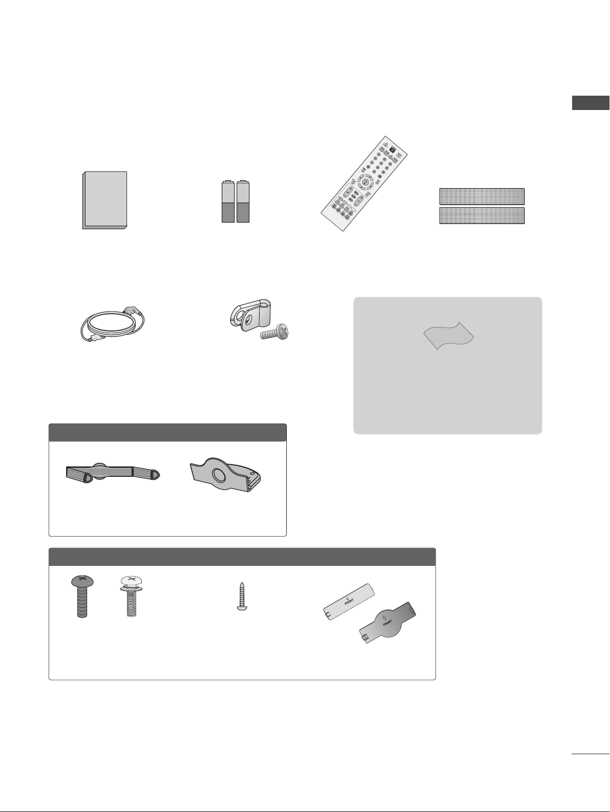
ACCESSORIES
ACCESSORIES
Ensure that the following accessories are included with your TV. If an accessory is missing, please contact the
dealer where you purchased the TV.
The accessories included may differ from the images below.
Batteries
Remote Control
Power Cord
Polishing Cloth
Polishing cloth for use on the screen.
Lightly wipe any stains or fingerprints on the surface
of the TV with the polishing cloth.
Do not use excessive force. This may cause scratching
or discolouration.
This feature is not available for all models.
OOnnllyy 2222LLGG3300
** **
Cable Management Clip Protection Cover
OOnnllyy 2266//3322//3377//4422LLGG3300
** **
Screw for stand fixing
(Refer to P.11)
Bolts for stand assembly
(Refer to P.8)
x 4 x 4
Protection Cover
(Refer to P.13)
or
(Only 26/32/37/42LG30**)
Owner’s Manual
Protective Bracket and Bolt for Power Cord
(This feature is not available for all models.)
(Refer to P.10)
Dual Lock™
(This feature is not available for
all models.)
(Refer to P.11)

ACCESSORIES
. . . . . . . . . . . . . . . . . . . . . . . . . . . . . . . . . . . . . . . . . . . . .
1
PREPARATION
Front Panel Controls . . . . . . . . . . . . . . . . . . . . . . . . 4
Back Panel Information . . . . . . . . . . . . . . . . . . . . . . 6
Stand Installation . . . . . . . . . . . . . . . . . . . . . . . . . . . 8
Please set it up carefully so the product
does not fall over . . . . . . . . . . . . . . . . . . . . . . . . . . . 9
Back Cover for Wire Arrangement . . . . . . . . . . . . . 10
Attaching the TV to a desk . . . . . . . . . . . . . . . . . . . 11
Swivel Stand . . . . . . . . . . . . . . . . . . . . . . . . . . . . . . . 11
Positioning your display . . . . . . . . . . . . . . . . . . . . . 12
Location . . . . . . . . . . . . . . . . . . . . . . . . . . . . . . . . . . 12
Kensington Security System . . . . . . . . . . . . . . . . . . 12
Protection cover . . . . . . . . . . . . . . . . . . . . . . . . . . . .13
Desktop Pedestal Installation . . . . . . . . . . . . . . . . . 14
Wall Mount: Horizontal installation . . . . . . . . . . . . 14
Antenna Connection . . . . . . . . . . . . . . . . . . . . . . . . 15
EXTERNAL EQUIPMENT SETUP
HD Receiver Setup . . . . . . . . . . . . . . . . . . . . . . . . 16
DVD Setup . . . . . . . . . . . . . . . . . . . . . . . . . . . . . . . . 18
VCR Setup . . . . . . . . . . . . . . . . . . . . . . . . . . . . . . . . 20
Other A/V Source Setup . . . . . . . . . . . . . . . . . . . . 22
Insertion of CI Module . . . . . . . . . . . . . . . . . . . . . . 22
PC Setup . . . . . . . . . . . . . . . . . . . . . . . . . . . . . . . . . 23
- Screen Setup for PC Mode . . . . . . . . . . . . . . . 26
WATCHING TV / PROGRAMME CONTROL
Remote Control Key Functions . . . . . . . . . . . . . . . 30
Turning on the TV . . . . . . . . . . . . . . . . . . . . . . . . . . 32
Programme Selection . . . . . . . . . . . . . . . . . . . . . . . 32
Volume Adjustment . . . . . . . . . . . . . . . . . . . . . . . . . 32
On-Screen Menus Selection and Adjustment . . . . 33
Auto Programme Tuning . . . . . . . . . . . . . . . . . . . . . 34
Manual Programme Tuning (In Digital Mode) . . . . 35
Manual Programme Tuning (In Analogue Mode) . . 36
Programme Edit . . . . . . . . . . . . . . . . . . . . . . . . . . . . 38
Booster . . . . . . . . . . . . . . . . . . . . . . . . . . . . . . . . . . 41
Software Update . . . . . . . . . . . . . . . . . . . . . . . . . . . 42
Diagnostics . . . . . . . . . . . . . . . . . . . . . . . . . . . . . . . 43
CI Information . . . . . . . . . . . . . . . . . . . . . . . . . . . . . 44
Selecting the Programme Table . . . . . . . . . . . . . . 45
Input Label . . . . . . . . . . . . . . . . . . . . . . . . . . . . . . . 46
EPG (ELECTRONIC PROGRAMME
GUIDE) (IN DIGITAL MODE)
Switch On/ Off EPG . . . . . . . . . . . . . . . . . . . . . . . . 47
Select Programme . . . . . . . . . . . . . . . . . . . . . . . . . . 47
Button Function in NOW/NEXT Guide Mode . . . . . 47
Button Function in 8 Day Guide Mode . . . . . . . . . . 48
Button Function in Date Change Mode . . . . . . . . . . 48
PICTURE CONTROL
Picture Size (Aspect Ratio) Control . . . . . . . . . . . . 49
Preset Picture Settings
- Picture Mode-Preset . . . . . . . . . . . . . . . . . . . . 51
-
Auto Colour Tone Control (Warm/Medium/Cool)
. . . . .52
Manual Picture Adjustment
- Picture Mode-User option . . . . . . . . . . . . . . . . 53
Picture Improvement Technology . . . . . . . . . . . . . . . . . 54
Advanced - Film Mode . . . . . . . . . . . . . . . . . . . . . . 55
Advanced - Black(Darkness) Level . . . . . . . . . . . . . 56
Eye Care . . . . . . . . . . . . . . . . . . . . . . . . . . . . . . . . . 57
Picture Reset . . . . . . . . . . . . . . . . . . . . . . . . . . . . . . 58
2
CONTENTS
CONTENTS

SOUND & LANGUAGE CONTROL
Auto Volume Leveler . . . . . . . . . . . . . . . . . . . . . . . . 59
Preset Sound Settings - Sound Mode . . . . . . . . . . 60
Sound Setting Adjustment - User Mode . . . . . . . . . . 61
Balance . . . . . . . . . . . . . . . . . . . . . . . . . . . . . . . . . . . 62
Audio Reset . . . . . . . . . . . . . . . . . . . . . . . . . . . . . . . 63
I/II
-
Stereo/Dual Reception (In Analogue Mode Only)
. . . . 64
-
NICAM Reception (In Analogue Mode Only) . . . . . . .
65
- Speaker Sound Output Selection . . . . . . . . . . 65
On-Screen Menu Language/Country Selection
. . . . . . . . 66
Language selection (In Digital Mode only) . . . . . . 67
TIME SETTING
Clock Setup . . . . . . . . . . . . . . . . . . . . . . . . . . . . . . . 68
Auto On/ Off Timer Setting . . . . . . . . . . . . . . . . . . 69
Auto Shut-off Setting . . . . . . . . . . . . . . . . . . . . . . . 70
Time Zone Setup . . . . . . . . . . . . . . . . . . . . . . . . . . . 70
Sleep Timer Setting . . . . . . . . . . . . . . . . . . . . . . . . . 71
Alarm setting . . . . . . . . . . . . . . . . . . . . . . . . . . . . . . 71
PARENTAL CONTROL / RATINGS
Set Password & Lock System . . . . . . . . . . . . . . . . . 72
Block Programme . . . . . . . . . . . . . . . . . . . . . . . . . . . 73
Parental Control . . . . . . . . . . . . . . . . . . . . . . . . . . . 74
Key Lock . . . . . . . . . . . . . . . . . . . . . . . . . . . . . . . . . . 75
TELETEXT
Switch On/ Off . . . . . . . . . . . . . . . . . . . . . . . . . . . . 76
SIMPLE Text . . . . . . . . . . . . . . . . . . . . . . . . . . . . . . . 76
TOP Text . . . . . . . . . . . . . . . . . . . . . . . . . . . . . . . . . 76
FASTEXT . . . . . . . . . . . . . . . . . . . . . . . . . . . . . . . . . 77
Special Teletext Functions . . . . . . . . . . . . . . . . . . . . 77
DIGITAL TELETEXT
Teletext within Digital Service . . . . . . . . . . . . . . . 78
Teletext in Digital Service . . . . . . . . . . . . . . . . . . 78
APPENDIX
Initializing (Reset to original factory setting) . . . . . 79
Troubleshooting . . . . . . . . . . . . . . . . . . . . . . . . . . . 80
Maintenance . . . . . . . . . . . . . . . . . . . . . . . . . . . . . . 82
Product Specifications . . . . . . . . . . . . . . . . . . . . . . 83
IR Codes . . . . . . . . . . . . . . . . . . . . . . . . . . . . . . . . . 84
External Control Device Setup . . . . . . . . . . . . . . . 86
3
CONTENTS
4
PREPARATION
PREPARATION
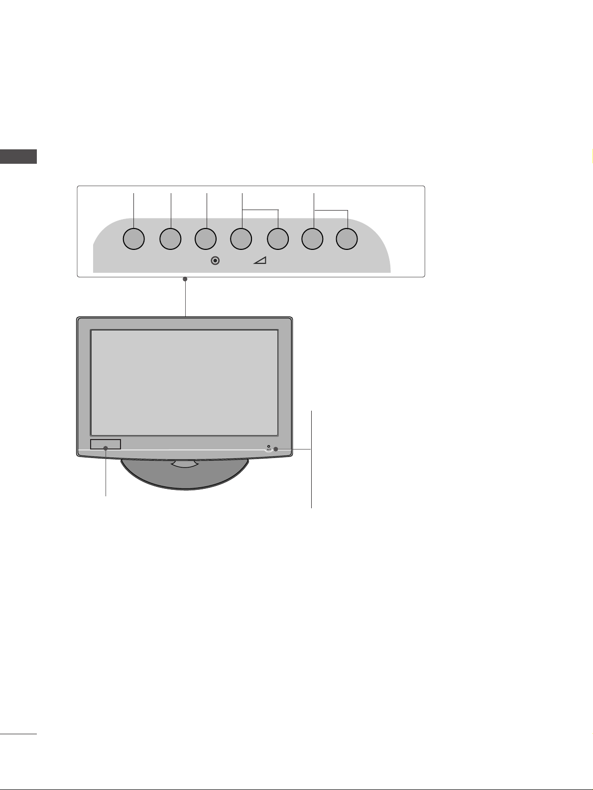
FRONT PANEL CONTROLS
■
Image shown may differ from your TV.
■
If your TV has a protection film attached, remove the film and then wipe the TV with a polishing cloth.
INPUT MENU P-+-+OK
PROGRAMMEVOLUME
MENU
OK
INPUT
22LG30
**
POWER
Remote Control Sensor
Power/Standby Indicator
• illuminates red in standby mode.
• illuminates blue when the TV is switched on.
Note:
You can adjust
PPoowweerr IInnddiiccaattoorr
in the OPTION
menu.
Clock LED
5
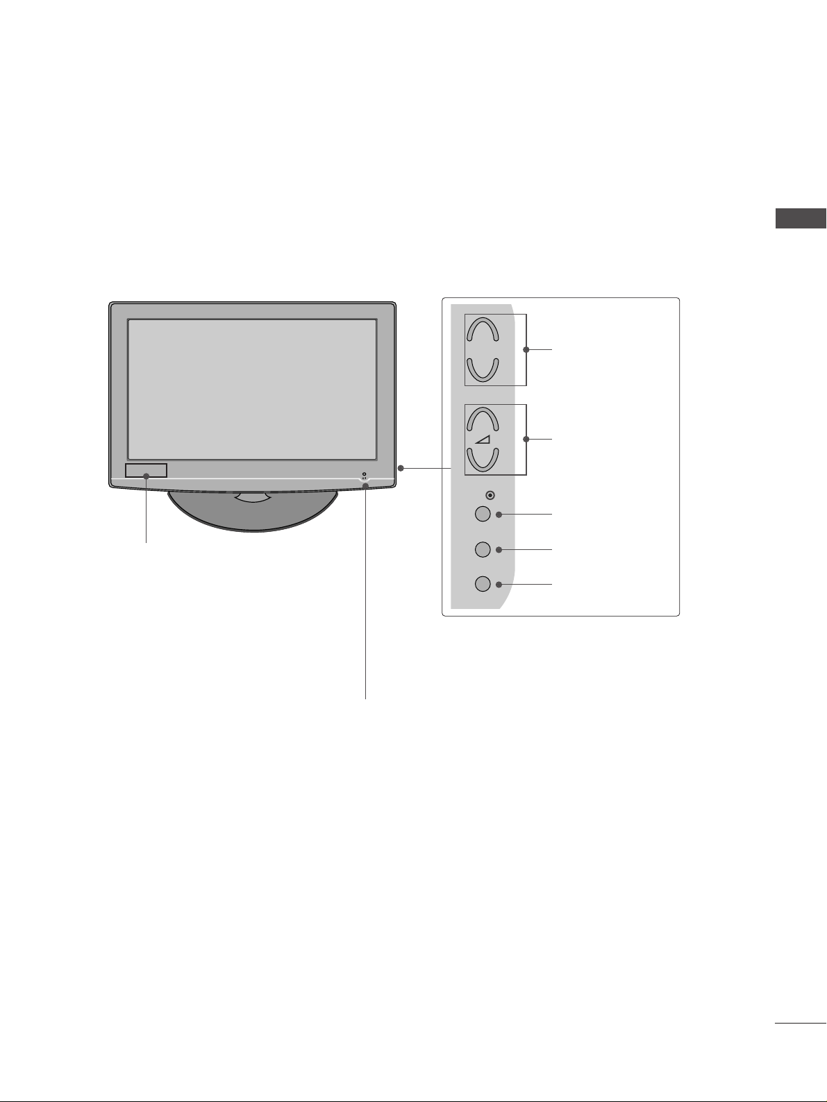
PREPARATION
26/32/37/42LG30
**
POWER
Remote Control Sensor
Power/Standby Indicator
• illuminates red in standby mode.
• illuminates blue when the TV is switched on.
Note:
You can adjust
PPoowweerr IInnddiiccaattoorr
in
the
OPTION menu.
P
MENU
INPUT
OK
+
-
+
-
PROGRAMME
VOLUME
OK
MENU
INPUT
Clock LED
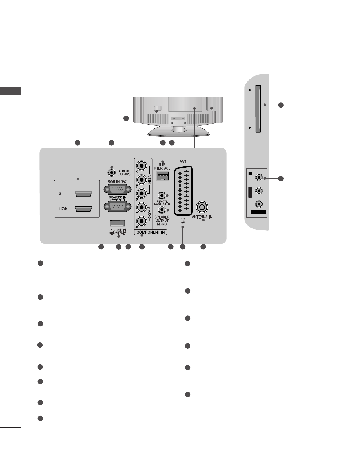
BACK PANEL INFORMATION
A
Image shown may differ from your TV.
6
PREPARATION
PREPARATION
( )
HDMI/DVI IN
2 3 4 5
AV IN 2V IN 2
L/MONOMONO
R
AUDIOAUDIO
PCMCIA CARD SLOT PCMCIA CARD SLOT
VIDEOVIDEO
( )
121186
7
9 10
13
14
22LG30
**
1
Power Cord Socket
This TV operates on an AC power. The voltage is
indicated on the Specifications page. Never
attempt to operate the TV on DC power.
HDMI Input
Connect a HDMI signal to HDMI IN. Or DVI (VIDEO)
signal to HDMI/DVI port with DVI to HDMI cable.
RGB/DVI Audio Input
Connect the audio from a PC or STB with DVI output.
RJP INTERFACE
Connect control line (RJ45) for RJP(Remote Jack pack)
Remote Control Port
RGB Input
Connect the output from a PC.
SERVICE ONLY PORT
RS-232C IN (CONTROL & SERVICE) PORT
Connect to the RS-232C port on a PC.
Component Input
Connect a component video/audio input to these
jacks.
SPEAKER OUTPUT(MONO)
The phone socket for external speaker is on this
jack.
Euro Scart Socket (AV1)
Connect scart socket from an external device to
this jack.
Antenna Input
Connect RF antenna to this jack.
PCMCIA (Personal Computer Memory Card
International Association) Card Slot
(This feature is not available in all countries.)
Audio/Video Input(AV2)
Connect audio/video output from an external
device to these jacks.
1
2
3
4
5
6
7
8
9
10
11
12
13
14
7
PREPARATION
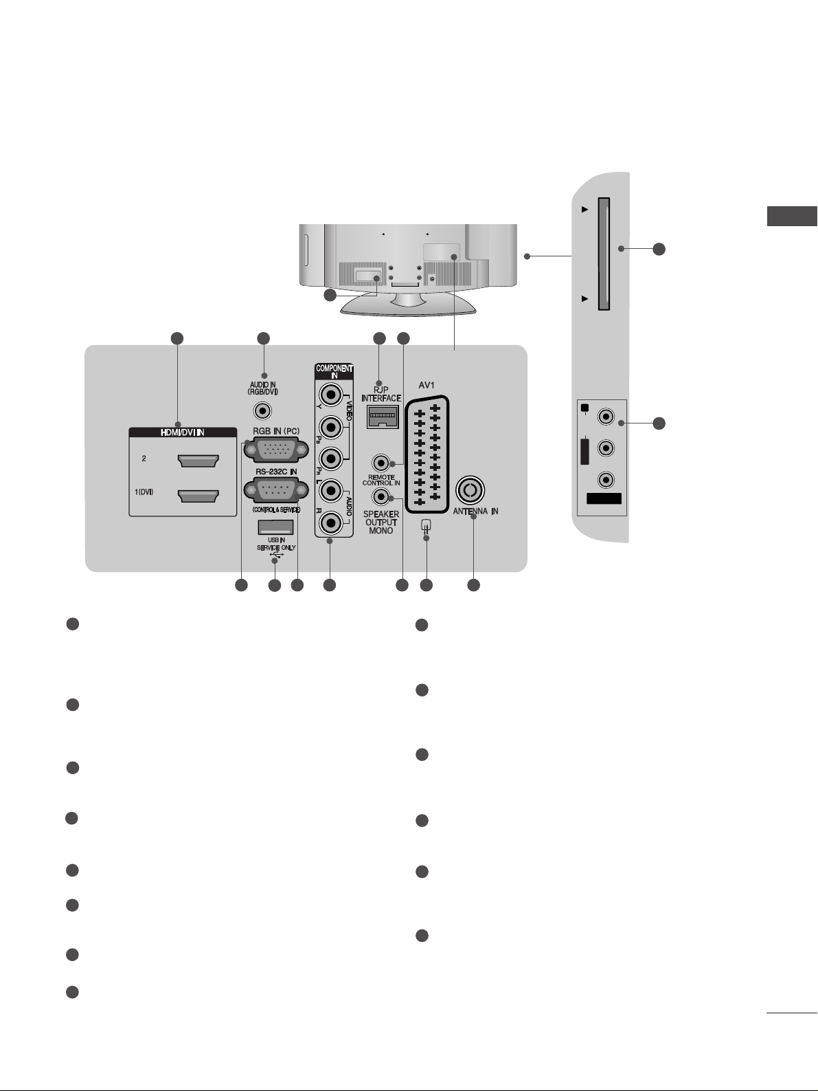
26/32/37/42LG30
**
( )
2 3 4 5
AV IN 2V IN 2
L/MONOMONO
R
AUDIOAUDIO
PCMCIA CARD SLOT PCMCIA CARD SLOT
VIDEOVIDEO
( )
121186
7
9 10
13
14
1
Power Cord Socket
This TV operates on an AC power. The voltage is
indicated on the Specifications page. Never
attempt to operate the TV on DC power.
HDMI Input
Connect a HDMI signal to HDMI IN. Or DVI (VIDEO)
signal to HDMI/DVI port with DVI to HDMI cable.
RGB/DVI Audio Input
Connect the audio from a PC or STB with DVI output.
RJP INTERFACE
Connect control line (RJ45) for RJP(Remote Jack pack)
Remote Control Port
RGB Input
Connect the output from a PC.
SERVICE ONLY PORT
RS-232C IN (CONTROL & SERVICE) PORT
Connect to the RS-232C port on a PC.
Component Input
Connect a component video/audio input to these
jacks.
SPEAKER OUTPUT(MONO)
The phone socket for external speaker is on this
jack.
Euro Scart Socket (AV1)
Connect scart socket from an external device to
this jack.
Antenna Input
Connect RF antenna to this jack.
PCMCIA (Personal Computer Memory Card
International Association) Card Slot
(This feature is not available in all countries.)
Audio/Video Input(AV2)
Connect audio/video output from an external
device to these jacks.
1
2
3
4
5
6
7
8
9
10
11
12
13
14

8
PREPARATION
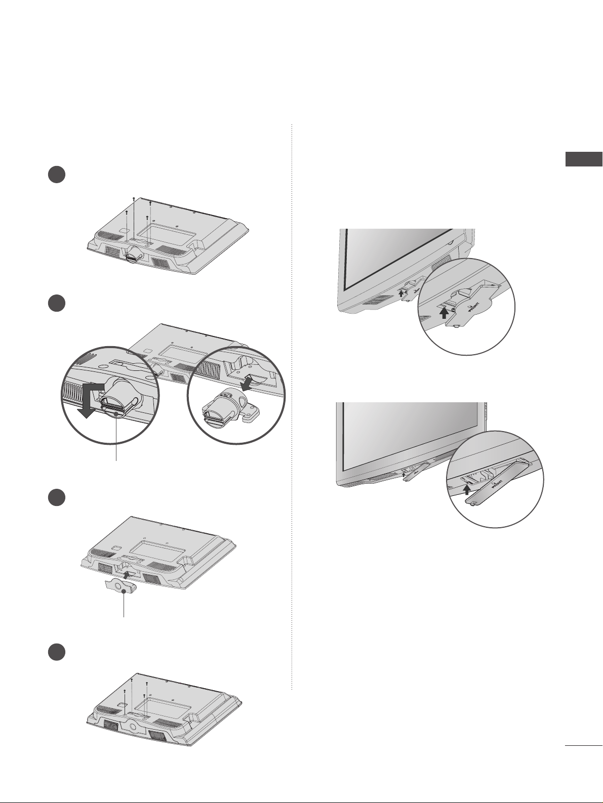
Stand installation
A
Image shown may differ from your TV.
Assemble the parts of the
SS TT AANNDD BBOODDYY
with
CC OOVVEERR BB AASSEE
of the TV. Insert the
SS TT AA NNDD
BBOO DDYY
into a
CC OOVVEERR BBAASSEE
until clicking sound.
2
Assemble the TV as shown.
3
For 22LG30
**
For 26/32/37/42LG30
**
SS TTAANN DD BBOO DDYY
CC OOVV EERR BBAA SSEE
Carefully place the TV screen side down on a
cushioned surface to protect the screen from
damage.
1
Assemble the parts of the
SS TT AANNDD BB OODDYY
with
CC OOVV EERR BBAA SSEE
of the TV.
2
Assemble the TV as shown.
3
Fix the 4 bolts securely using the holes in the
back of the TV.
4
SS TTAANN DD BBOO DDYY
CC OOVV EERR BBAA SSEE
Carefully place the TV screen side down on a
cushioned surface to protect the screen from
damage.
1
9
PREPARATION
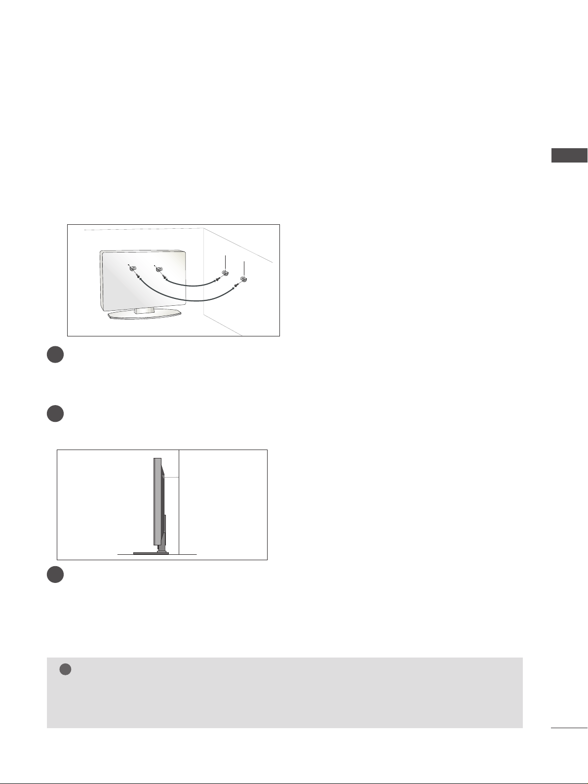
PLEASE SET IT UP CAREFULLY SO THE PRODUCT DOES NOT
FALL OVER.
■
You should purchase necessary components to fix the TV to the wall on the market.
■
Position the TV close to the wall to avoid the possibility of it falling when pushed.
■
The instructions shown below are a safer way to set up the TV, which is to fix it to the wall, avoiding the
possibility of it falling forwards if pulled. This will prevent the TV from falling forward and causing injury. This
will also prevent the TV from damage. Ensure that children do not climb or hang from the TV.
NOTE
!
G
When moving the TV undo the cords first.
G
Use a platform or cabinet strong and large enough to support the size and weight of the TV.
G
To use the TV safely make sure that the height of the bracket on the wall and on the TV is the same.
3
1
2
Use the eye-bolts or TV brackets/bolts to fix the TV to the wall as shown in the picture.
(If your TV has bolts in the eyebolts, loosen these bolts.)
* Insert the eye-bolts or TV brackets/bolts and tighten them securely in the upper holes.
Secure the wall brackets with the bolts on the wall. Match the height of the bracket that is mounted on the
wall.
3
Use a sturdy rope to tie the TV. It is safer to tie the rope so it becomes horizontal between the wall and the
TV.
2
1
10
PREPARATION
PREPARATION
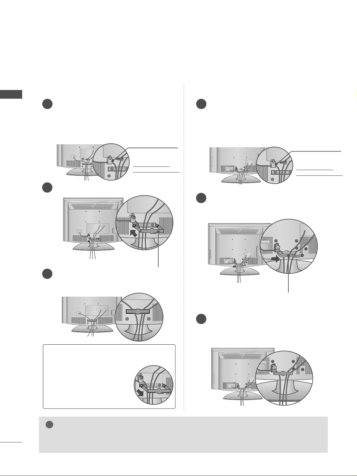
BACK COVER FOR WIRE ARRANGEMENT
A
Image shown may differ from your TV.
Connect the cables as necessary.
To connect additional equipment, see the
EXTERNAL EQUIPMENT SETUP section.
Secure the power cable with the PROTECTIVE
BRACKET and the screw as shown. It will help prevent
the power cable from being removed by accident.
Install the CABLE MANAGEMENT CLIP as shown.
1
2
Fit the CABLE MANAGEMENT CLIP as shown.
3
Connect the cables as necessary.
To connect additional equipment, see the
EXTERNAL EQUIPMENT SETUP section.
Secure the power cable with the PROTECTIVE
BRACKETand the screw as shown. It will help prevent
the power cable from being removed by accident.
Install the CABLE MANAGEMENT CLIP as
shown.
1
2
Put the cables inside the CABLE MANAGEMENT
CLIP and snap it closed.
3
For 26/32/37/42LG30
**
For 22LG30
**
GG
Do not hold the CABLE MANAGEMENT CLIP when moving the TV.
- If the TV is dropped, you may be injured or the product may be broken.
NOTE
!
GG
Hold the CABLE MANAGEMENT CLIP with both hands
and pull it backward.
How to remove the
CABLE MANAGEMENT CLIP
PROTECTIVE
BRACKET
(This feature is not
available for all models.)
PROTECTIVE
BRACKET
(This feature is not
available for all models.)
CABLE MANAGEMENT CLIP
CABLE MANAGEMENT CLIP
11
PREPARATION
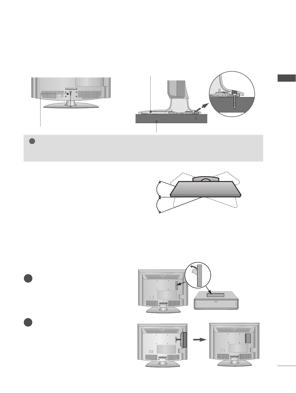
Attaching the TV to a desk (Only 26/32/37/42LG30
**
)
WARNING
!
GG
To prevent TV from falling over, the TV should be securely attached to the floor/wall per installation
instructions. Tipping, shaking, or rocking the machine may cause injury.
The TV must be attached to desk so it cannot be pulled in a forward/backward direction, potentially causing
injury or damaging the product. Use only an attached screw.
1-Screw
(provided as parts of the product)
Desk
Stand
Swivel Stand
(Only 26/32/37/42LG30**)
After installing the TV, you can adjust the TV manually
to the left or right direction by 20 degrees to suit your
viewing position.
How to use Dual Lock™ (This feature is not available for all models.)
Fix the set-top box to the TV and use it when you want to.
After removing the protection paper from
the Dual Lock, stick it to the TV and the
set-top box as shown.
Attach the set-top box to the TV by pressing
the Velcro strips together.
1
2
12
PREPARATION
PREPARATION
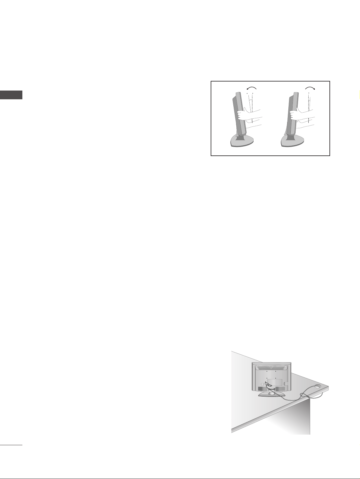
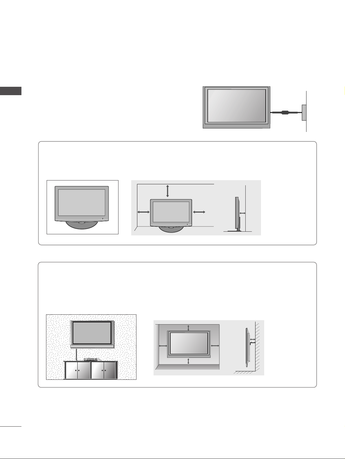
POSITIONING YOUR DISPLAY
(Only 22LG30**)
■
Image shown may differ from your TV.
■
Adjust the position of the panel in various ways for
maximum comfort.
• Tilt range
LOCATION
(Only 22LG30**)
Position your TV so that no bright light or sunlight falls directly onto the screen. Care should be taken not to
expose the tv to any unnecessary vibration, moisture, dust or heat. Also ensure that the TV is placed in a position
to allow a free flow of air. Do not cover the ventilation openings on the back cover.
If you intend to mount the TV to a wall, attach VESA standard mounting interface (optional parts) to the back of
the TV.
When you install the TV to use the wall mounting bracket (optional parts), fix it carefully so as not to drop.
KENSINGTON SECURITY SYSTEM (Only 22LG30
**
)
The TV is equipped with a Kensington Security System connector on the back panel. Connect the Kensington
Security System cable as shown below.
For the detailed installation and use of the Kensington Security System, refer to the user’s guide provided with
the Kensington Security System.
For further information, contact http://www.kensington.com, the internet homepage of the Kensington
company. Kensington sells security systems for expensive electronic equipment such as notebook PCs and LCD
projectors.
NOTE
- The Kensington Security System is an optional accessory.
NOTES
a. If the TV feels cold to the touch, there may be a small “flicker” when
when it is turned on.
This is normal, there is nothing wrong with TV.
b. Some minute dot defects may be visible on the screen, appearing as
tiny red, green, or blue spots. However, they have no adverse effect on
the monitor's performance.
c. Avoid touching the LCD screen or holding your finger(s)
against it for long periods of time.
Doing so may produce some temporary distortion effects on the screen.
12
0
3
0
13
PREPARATION
PROTECTION COVER
For 22LG30
**
For 26/32/37/42LG30
**
HHIINNGGEE BBOODDYY
■
Image shown may differ from your TV.
When installing the wall-mounted unit, use the protection cover for desk-type stand installation. Insert
the
PP RROOTTEECCTTIIOONN CCOOVVEE RR
into the TV until click-
ing sound.
Loose the bolts from TV.
1
Insert the
PP RROO TT EECCTTIIOO NN CC OOVV EERR
into the TV.
3
PP RROO TT EECCTTIIOO NN CCOOVVEERR
Bend the
HHIINNGGEE BBOODDYY
and pull it backward.
2
Fix the 4 bolts securely using the holes in the
back of the TV.
4
or
14
PREPARATION
DESKTOP PEDESTAL INSTALLATION
For adequate ventilation allow a clearance of 4” (10cm) all around the TV.
EARTHING
Ensure that you connect the earth wire to prevent possible
electric shock. If grounding methods are not possible, have a
qualified electrician install a separate circuit breaker.
Do not try to earth the TV by connecting it to telephone
wires, lightening rods or gas pipes.
Power Supply
Circuit
breaker
■
The TV can be installed in various ways such as on a wall, or on a desktop etc.
■
The TV is designed to be mounted horizontally.
4 inches
4 inches 4 inches 4 inches
WALL MOUNT: HORIZONTAL INSTALLATION
For adequate ventilation allow a clearance of 4” (10cm) all around the TV. We recommend that you
use a wall mounting bracket of LG brand when mounting the TV to a wall.
4 inches
4 inches
4 inches 4 inches
4 inches
15
PREPARATION
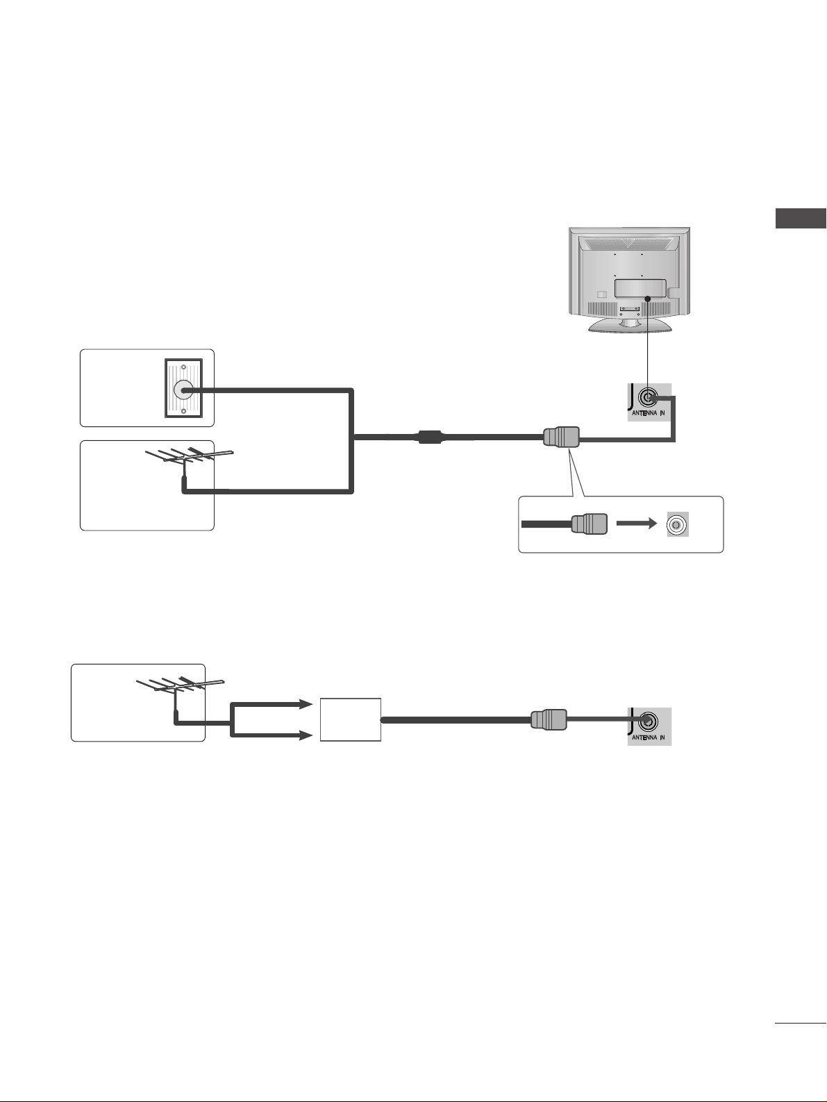
■
For optimum picture quality, adjust antenna direction.
■
An antenna cable and converter are not supplied.
Multi-family Dwellings/Apartments
(Connect to wall antenna socket)
Single-family Dwellings /Houses
(Connect to wall jack for outdoor antenna)
Outdoor
Antenna
(VHF, UHF)
Wall
Antenna
Socket
RF Coaxial Wire (75 ohm)
ANTENNA CONNECTION
Antenna
UHF
Signal
Amplifier
VHF
■
In poor signal areas, to achieve better picture quality it may be necessary to install a signal amplifier to the
antenna as shown above.
■
If signal needs to be split for two TVs, use an antenna signal splitter for connection.
■
To prevent damage do not connect to the mains outlet until all connections are made between the devices.
16
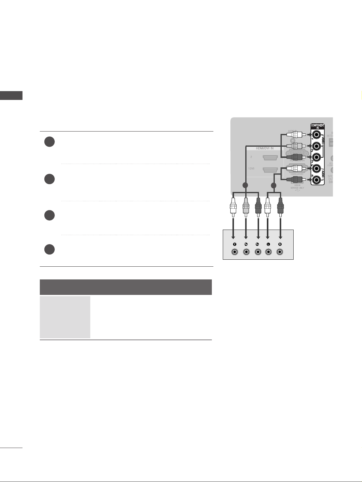
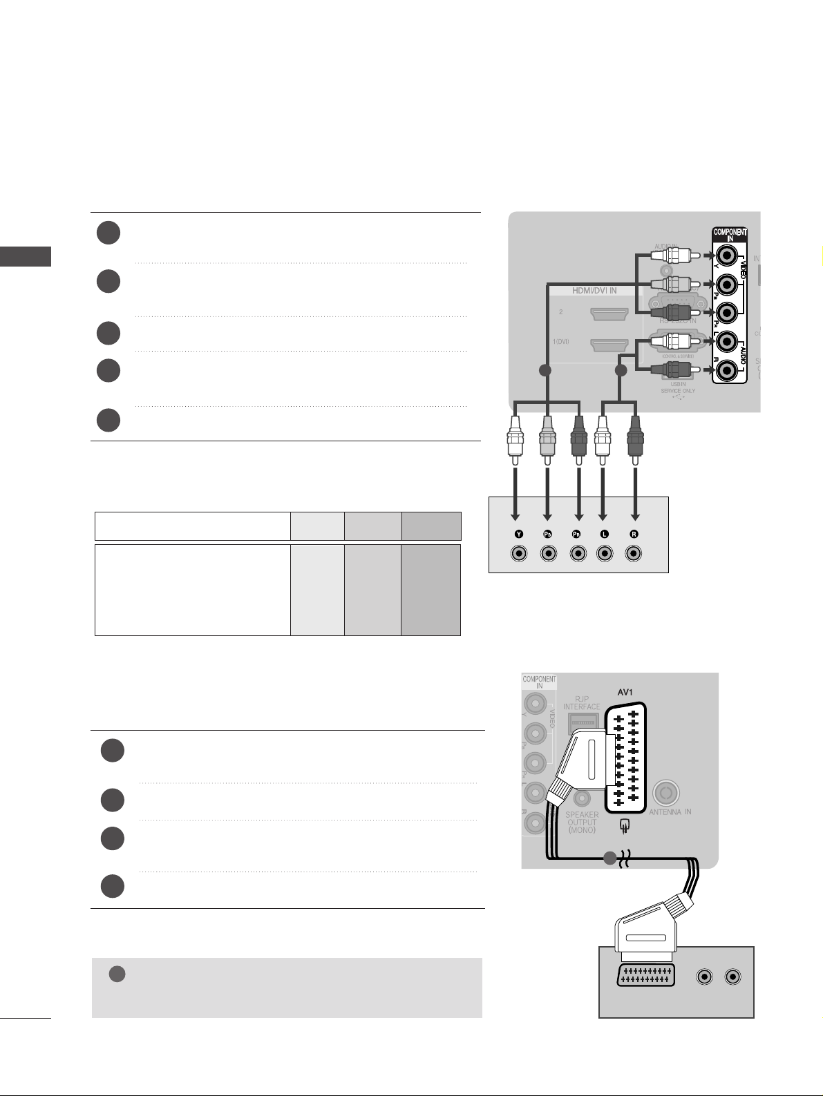
EXTERNAL EQUIPMENT SETUP
PREPARATION
Connect the video outputs (Y, PB
, PR
)
of the digital set
top box to the
CC OOMMPPOO NNEENN TT IINN VVIIDDEEOO
jacks on the TV.
Connect the audio output of the digital set-top box to
the
CC OOMMPPOO NNEENN TT IINN AA UUDDIIOO
jacks on the TV.
Turn on the digital set-top box.
(
Refer to the owner’s manual for the digital set-top box.
)
Select
CCoomm pp oonnee nntt
input source using the
II NN PP UU TT
button
on the remote control.
2
3
4
1
HD RECEIVER SETUP
■
To avoid damaging any equipment, never plug in any power cords until you have finished connecting all equipment.
■
This section on EXTERNAL EQUIPMENT SETUP mainly uses diagrams for the 26LG30**models.
Connecting with a component cable
1
2
Signal
480i/576i
480p/576p
720p/1080i
10 8 0 p
Component
Yes
Yes
Yes
Yes
HDMI
No
Yes
Yes
Yes
■
This TV can receive Digital RF/Cable signals without an external digital set-top box. However, if you do receive
Digital signals from a digital set-top box or other digital external device, refer to the diagram as shown below.
17
EXTERNAL EQIPMENT SETUP
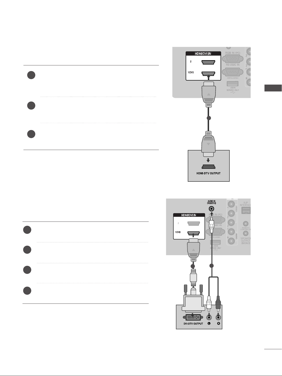
Connecting a set-top box with an HDMI cable
Connect the HDMI output of the digital set-top box to the
HHDDMMII// DDVV II IINN 11 (( DDVV II ))
or
HHDDMMII// DDVV II IINN 22
jack on the
TV.
Turn on the digital set-top box.
(
Refer to the owner’s manual for the digital set-top box.
)
Select HDMI1 or HDMI2 input source using the
II NNPPUUTT
but-
ton on the remote control.
2
3
1
HDMI/DVI INHDMI/DVI IN
1
Connect the digital set-top box to
HHDDMMII// DDVVII IINN
11((DDVV II))
jack on the TV.
Connect the audio output of the digital set-top box to
the
AA UUDDIIOO IINN ((RRGGBB//DDVVII))
jack on the TV.
Turn on the digital set-top box. (Refer to the owner’s
manual for the digital set-top box.
)
Select
HHDD MMII 11
input source using the
II NNPPUUTT
button
on the remote control.
2
3
4
1
Connecting with a HDMI to DVI cable
1
2
18
EXTERNAL EQUIPMENT SETUP
EXTERNAL EQIPMENT SETUP
DVD SETUP
When connecting with a component cable
Component Input ports
To achieve better picture quality, connect a DVD player to
the component input ports as shown below.
Component ports on the TV
YPBP
R
Video output ports
on DVD player
Y
Y
Y
Y
PB
B-Y
Cb
Pb
P
R
R-Y
Cr
Pr
Connect the video outputs (Y, P
B, PR
)
of the DVD to the
CC OOMMPPOO NNEENN TT IINN VVIIDDEEOO
jacks on the TV.
Connect the audio outputs of the DVD to the
CC OOMMPPOO NNEENN TT IINN AA UUDDIIOO
jacks on the TV.
Turn on the DVD player, insert a DVD.
Select
CCoomm pp oonnee nntt
input source using the
II NNPPUUTT
button
on the remote control.
Refer to the DVD player's manual for operating instructions.
2
3
4
5
1
1 2
(R) AUDIO (L)
AUDIO/
VIDEO
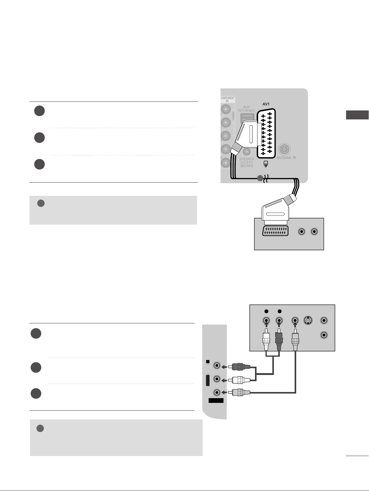
Connecting with a Euro Scart cable
Connect the Euro scart socket of the DVD to the
AA VV 11
Euro scart socket on the TV.
Turn on the DVD player, insert a DVD.
Select
AAVV11
input source using the
II NN PP UU TT
button on the
remote control.
Refer to the DVD player's manual for operating instructions.
2
3
4
1
1
NOTE
!
GG
Any Euro scart cable used must be signal shielded.
19
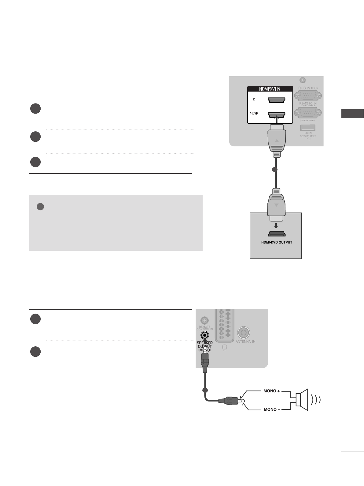
EXTERNAL EQIPMENT SETUP
SPEAKER OUTPUT SETUP
HDMI/DVI INHDMI/DVI IN
Connecting the HDMI cable
Connect the HDMI output of the DVD to the
HHDDMMII// DDVV II IINN 11((DDVV II ))orHHDDMMII// DDVV II IINN 22
jack on
the TV.
Select
HHDDMMII11orHHDDMMII22
input source using the
II NN PP UU TT
button on the remote control.
Refer to the DVD player's manual for operating instructions.
2
3
1
Connect the external speaker to the
SS pp eeaakkeerr
oouu tt pp uutt(( MMOONN OO))
jack on the TV.
Refer to the ‘Speaker & Speaker Stand’ manual for
operating instructions.
2
1
1
GG
The TV can receive video and audio signals simultaneously
when using a HDMI cable.
GG
If the DVD does not support Auto HDMI, you must set the
output resolution appropriately.
NOTE
!
( )
1
20
EXTERNAL EQUIPMENT SETUP
EXTERNAL EQIPMENT SETUP
VCR SETUP
■
To avoid picture noise (interference), allow adequate distance between the VCR and TV.
■
If 4:3 picture format is used for an extended period the fixed images on the sides of the screen may remain
visible.
OUTPUT
SWITCH
ANT IN
R
S-VIDEO VIDEO
ANT OUT
L
R
AUDIO
Wall Jack
Antenna
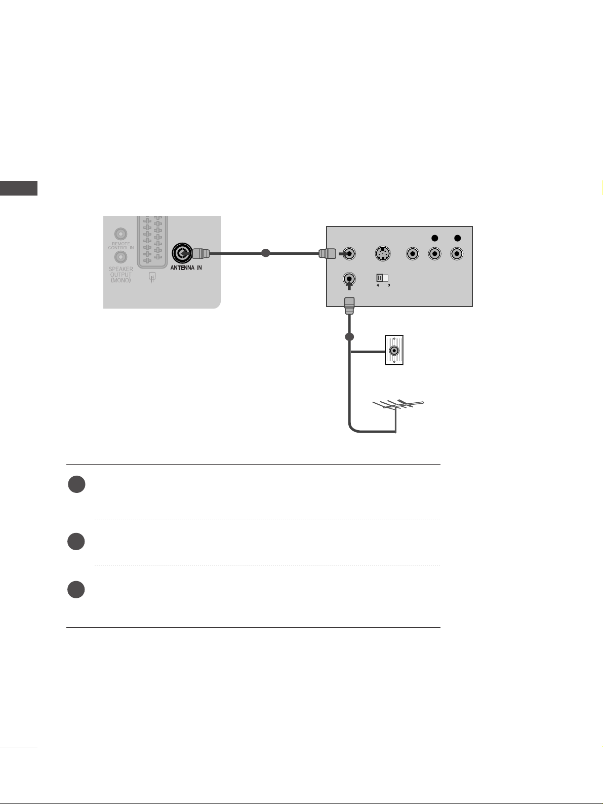
1
2
When connecting with a RF Cable
Connect the
AA NNTT OO UU TT
socket of the VCR to the
AA NNTTEE NNNN AA IINN
socket on the
TV.
Connect the antenna cable to the
AA NNTT IINN
socket of the VCR.
Press the PLAY button on the VCR and match the appropriate channel between
the TV and VCR for viewing.
1
2
3
21
EXTERNAL EQIPMENT SETUP
(R) AUDIO (L)
AUDIO/
VIDEO
AV IN 2
L/ MONO
R
AUDIO
VIDEO
Connecting with a Euro Scart cable
Connect the Euro scart socket of the VCR to the
AA VV 11
Euro scart socket on the TV.
Insert a video tape into the VCR and press PLAY on
the VCR. (Refer to the VCR owner’s manual.)
Select
AAVV11
input source using the
II NN PP UU TT
button on
the remote control.
2
3
1
1
NOTE
!
GG
Any Euro scart cable used must be signal shielded.
Connecting with a RCA cable
AV IN 2
L/L/MONOMONO
R
AUDIOAUDIO
VIDEOVIDEO
L
R
S-VIDEO
VIDEO
OUTPUT
SWITCH
ANT IN
ANT OUT
Connect the
AA UU DD II OO/VV IIDD EEOO
jacks between TV and
VCR. Match the jack colours (Video = yellow, Audio Left
= white, and Audio Right = red)
Insert a video tape into the VCR and press PLAY on
the VCR. (Refer to the VCR owner’s manual.
)
Select
AAVV22
input source using the
II NN PP UU TT
button on
the remote control.
1
2
3
GG
If you have a mono VCR, connect the audio cable from the
VCR to the
AA UU DDIIOO LL//MMOO NNOO
jack of the TV.
NOTE
!
22
EXTERNAL EQUIPMENT SETUP
EXTERNAL EQIPMENT SETUP
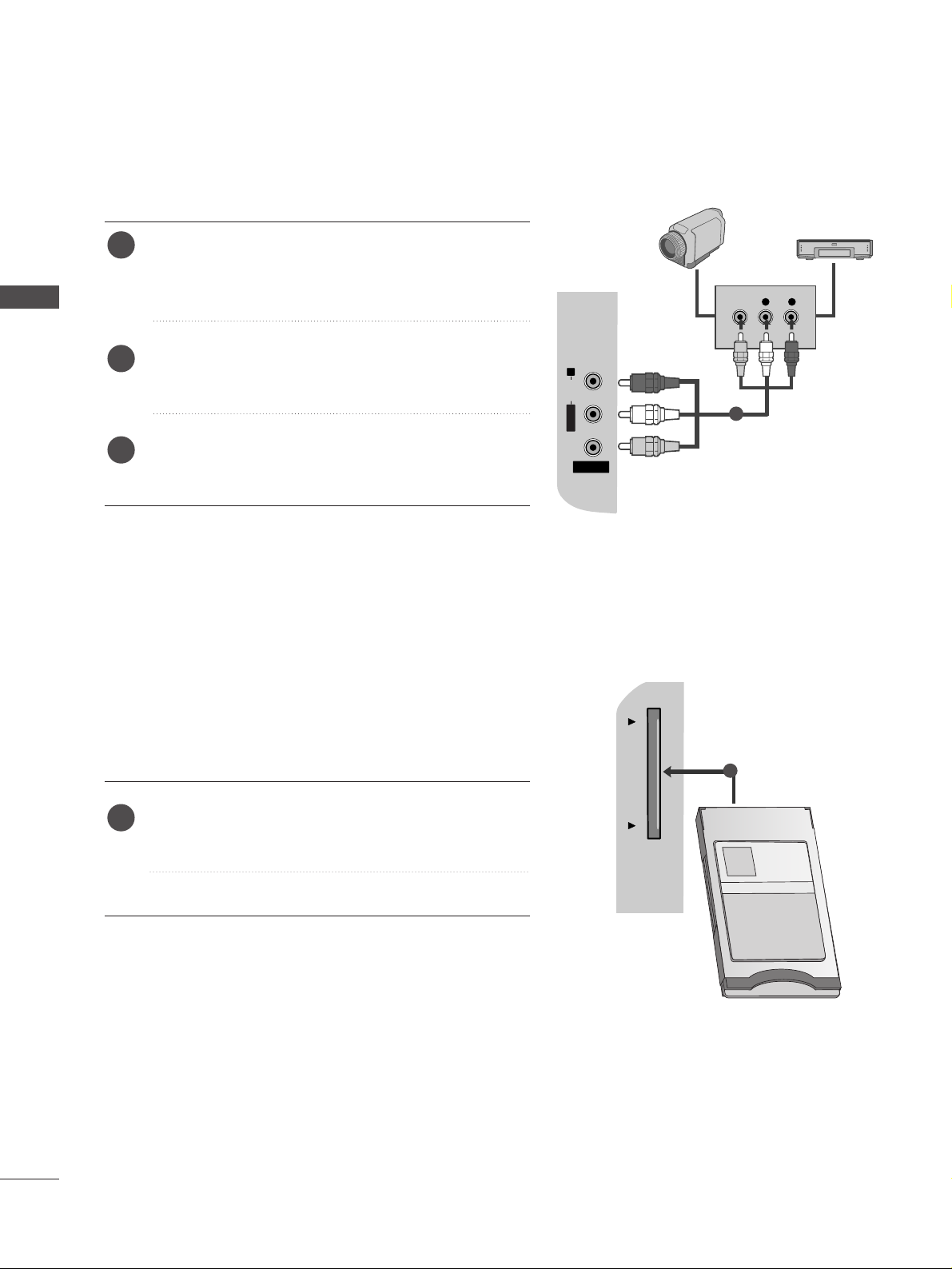
Insert the CI Module to
PP CC MMCC IIAA
(Personal Computer
Memory Card International Association)
CC AARRDD SS LL OOTT
of TV as shown.
For further information, see p.44
1
INSERTION OF CI MODULE
TVTVTV
PCMCIA CARD SLOT PCMCIA CARD SLOT
-- TT oo vvii eeww tthh ee eennccrryy ppttee dd (( ppaayy )) ss eerrvvii cc eess iinn dd iiggiittaa ll TTVV
mm oo dd ee ..
-- TT hh iiss ffeeaattuu rree ii ss nnoott aavv aaii llaa bb ll ee iinn aallll cc oouu nn ttrrii eess ..
1
L R
VIDEO
AV IN 2V IN 2
L/L/MONOMONO
R
AUDIOAUDIO
VIDEOVIDEO
Connect the
AA UU DDIIOO/VV IIDD EEOO
jacks between TV and
external equipment. Match the jack colours
.
(
Video =
yellow, Audio Left = white, and Audio Right = red
)
Select
AA VV22
input source using the
II NNPPUUTT
button on
the remote control.
Operate the corresponding external equipment.
Refer to external equipment operating guide.
2
3
1
1
Camcorder
Video Game Set
OTHER A/V SOURCE SETUP
23
EXTERNAL EQIPMENT SETUP
PC SETUP
This TV provides Plug and Play capability, meaning that the PC adjusts automatically to the TV's settings.
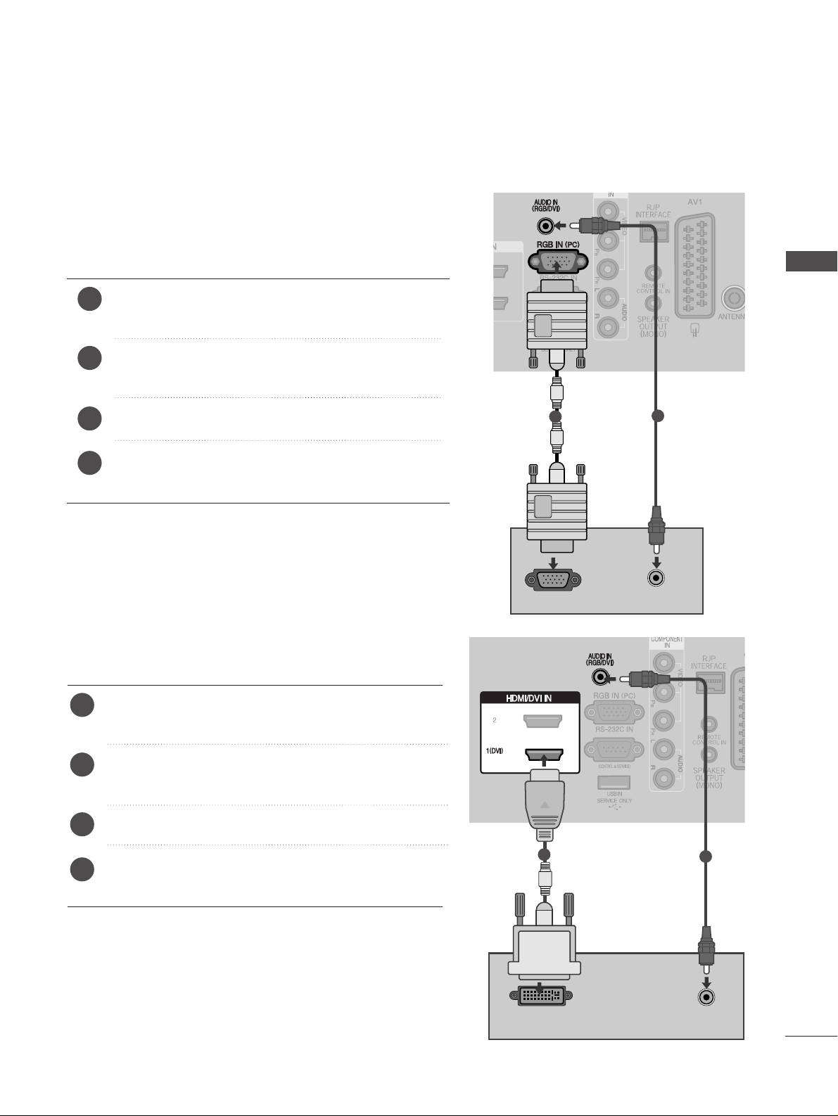
Connecting with a D-sub 15 pin cable
AUDIO
RGB OUTPUT
1
2
4
Connect the RGB output of the PC to the
RRGG BB IINN
(( PPCC))
jack on the TV.
Connect the PC audio output to the
AA UU DDIIOO IINN
(( RRGG BB//DDVVII))
jack on the TV.
Turn on the PC and the TV
Select
RRGGBB
input source using the INPUT button on
the remote control.
2
3
1
DVI-PC OUTPUT
HDMI/DVI IN
AUDIO
Connecting with a HDMI to DVI cable
Connect the DVI output of the PC to the
HHDDMMII// DDVVII II NN
11((DDVV II))
jack on the TV.
Connect the PC audio output to the
AA UUDDIIOO IINN
(( RRGG BB//DD VVII))
jack on the TV.
Turn on the PC and the TV.
Select
HHDD MMII 11
input source using the
II NNPPUUTT
button
on the remote control.
2
3
4
1
1
2
24
EXTERNAL EQUIPMENT SETUP
EXTERNAL EQIPMENT SETUP
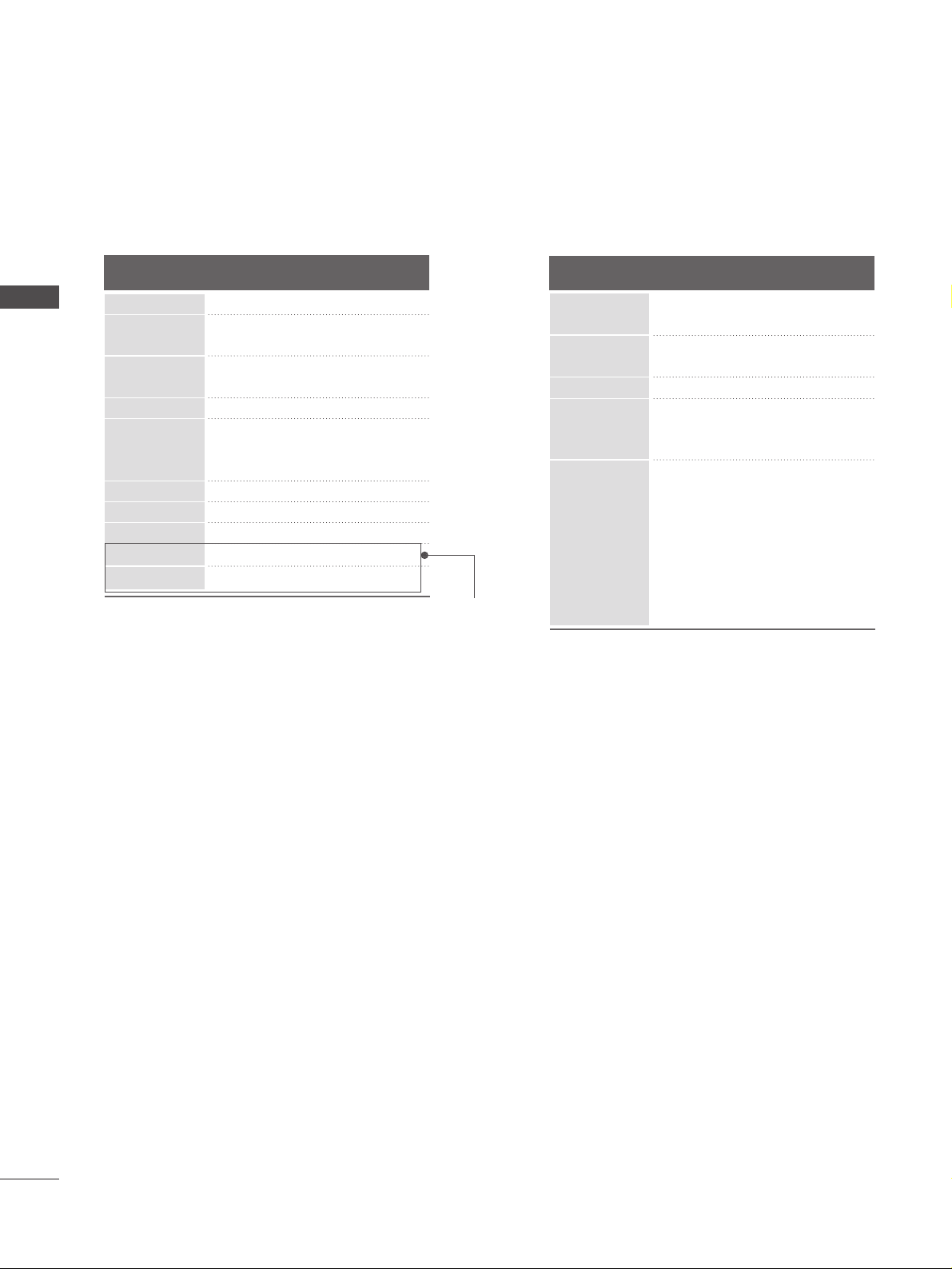
Supported Display Resolution
70.08
59.94
75.00
60.31
75.00
74.55
60.00
70.00
75.029
59.87
59.8
59.6
59.948
59.954
RGB[PC], HDMI[PC] mode
31.469
31.469
37. 684
37. 879
46.875
49.725
48.363
56.470
60.123
47. 78
47. 72
47. 56
64.744
62.290
Resolution
640x480
800x600
832x624
720x400
1024x768
Horizontal
Frequency(kHz)
Vertical
Frequency(Hz)
1280x768
1360x768
1366x768
1400x1050
1680x1050
HDMI[DTV] mode
* Only 22LG30
**
59.94
60.00
59.94
60.00
50.00
50
59.94
60.00
59.94
60.00
50.00
24.00
30.00
50.00
59.94
60.00
31.469
31.469
31.47
31.50
31.25
37. 500
44.96
45.00
33.72
33.75
28.12
27.000
33.75
56.25
67. 43
67. 5
Resolution
640x480
720x480
720x576
1280x720
1920x1080
Horizontal
Frequency(kHz)
Vertical
Frequency(Hz)

25
EXTERNAL EQIPMENT SETUP
NOTE
!
G
To enjoy vivid picture and sound, connect a PC to
the TV.
G
Avoid keeping a fixed image on the TV’s screen for
prolonged periods of time. The fixed image may
become permanently imprinted on the screen; use
a screen saver when possible.
G
Connect the PC to the RGB (PC) or HDMI/DVI IN
port of the TV; change the resolution.
G
There may be interference relating to resolution,
vertical pattern, contrast or brightness in PC
mode. Change the PC mode to another resolution
or change the refresh rate to another rate or
adjust the brightness and contrast on the menu
until the picture is clear. If the refresh rate of the
PC graphic card can not be changed, change the
PC graphic card or consult the manufacturer of
the PC graphic card.
G
The synchronization input waveform for
Horizontal and Vertical frequencies are separate.
G
Connect the signal cable from the monitor output
port of the PC to the RGB (PC) port of the TV or
the signal cable from the HDMI output port of the
PC to the HDMI/DVI IN port on the TV.
G
Connect the audio cable from the PC to the Audio
input on the TV. (Audio cables are not included
with the TV).
G
If using a sound card, adjust PC sound as required.
G
This TV uses a VESA Plug and Play Solution. The
TV provides EDID data to the PC system with a
DDC protocol. The PC adjusts automatically when
using this TV.
G
DDC protocol is preset for RGB (Analog RGB),
HDMI (Digital RGB) mode.
G
If required, adjust the settings for Plug and Play
functionality.
G
If the graphic card on the PC does not output
analogue and digital RGB simultaneously, connect
only one of either RGB or HDMI IN (or HDMI/DVI
IN) to display the PC output on the TV.
G
If the graphic card on the PC does output
analogue and digital RGB simultaneously, switch
the TV to either RGB or HDMI; (the other mode is
set to Plug and Play automatically by the TV.)
G
DOS mode may not work depending on the video
card if you use a HDMI to DVI cable.
G
If you use too long an RGB-PC cable, there may be
interference on the screen. We recommend using
under 5m of cable. This provides the best picture
quality.
26
EXTERNAL EQUIPMENT SETUP
EXTERNAL EQIPMENT SETUP
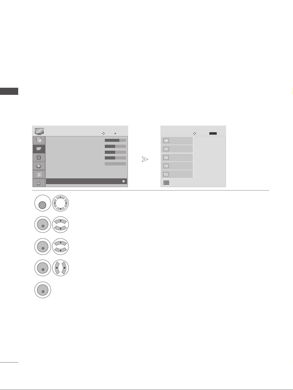
Screen Setup for PC mode
Returns to the default settings Position, Size and Phase at the factory.
This function works in the following mode : RGB[PC].
Screen Reset
1
Select PICTURE.
2
Select SCREEN.
3
Select Reset.
5
Run Reset.
• Contrast : 70
• Brightness : 50
• Sharpness : 50
• Colour : 50
• Tint : 0
• Advanced Control
• Picture Reset
PICTURE
Move
OK
D
Screen
To S e t
Auto Config.
SCREEN
Move
Prev.
BACK
Resolution
Position
Size
Phase
Reset
G
MENU
OK
OK
OK
4
Select Ye s .
OK
• Press the MENU or EXIT button to return to normal TV viewing.
• Press the BACK button to move to the previous menu screen.
 Loading...