

LG 22EB23TM-B User guide

ENGLISH
OWNER’S MANUAL
LED LCD MONITOR
Please read this manual carefully before operating
your set and retain it for future reference.
LED LCD
22EB23TM
MONITOR MODEL
www.lg.com

TABLE OF CONTENTS
2
ENGLISH
ENG
CONTENTS
3
ASSEMBLING AND PREPAR-
ING
3 Unpacking
4 Parts and buttons
5 Setting up the Monitor set
5 - Attaching the Stand Base
5 - Detaching the stand base
6 - Detaching the stand body
6 - Using the cable holder
7 - Mounting on a table
7 - Adjusting the angle
8 - Adjusting the stand height
8 - Using the Kensington locking device
9 - Swivel stand
9 - Using the Pivot function
10 - Mounting on a wall
25
TROUBLESHOOTING
27 SPECIFICATIONS
27 22EB23TM
28 Preset Modes (Resolution)
28 Indicator
PROPER POSTURE
29
29 Proper posture for using the Monitor set.
11
USING THE MONITOR SET
11 Connecting to a PC
11 - D-SUB connection
11 - DVI-D connection
14
CUSTOMIZING SETTINGS
15 Customizing Settings
15 - Menu Settings
16 - Picture
17 - Color
18 - Display
19 - Others
20
MY KEY Setting
21 FUNC. Setting
21 - Picture Mode
22 - SUPER ENERGY SAVING
23 - DUAL DISPLAY
23 - DUAL WEB
24 - MY KEY Setting
ASSEMBLING AND PREPARING
3
ASSEMBLING AND PREPARING
Unpacking
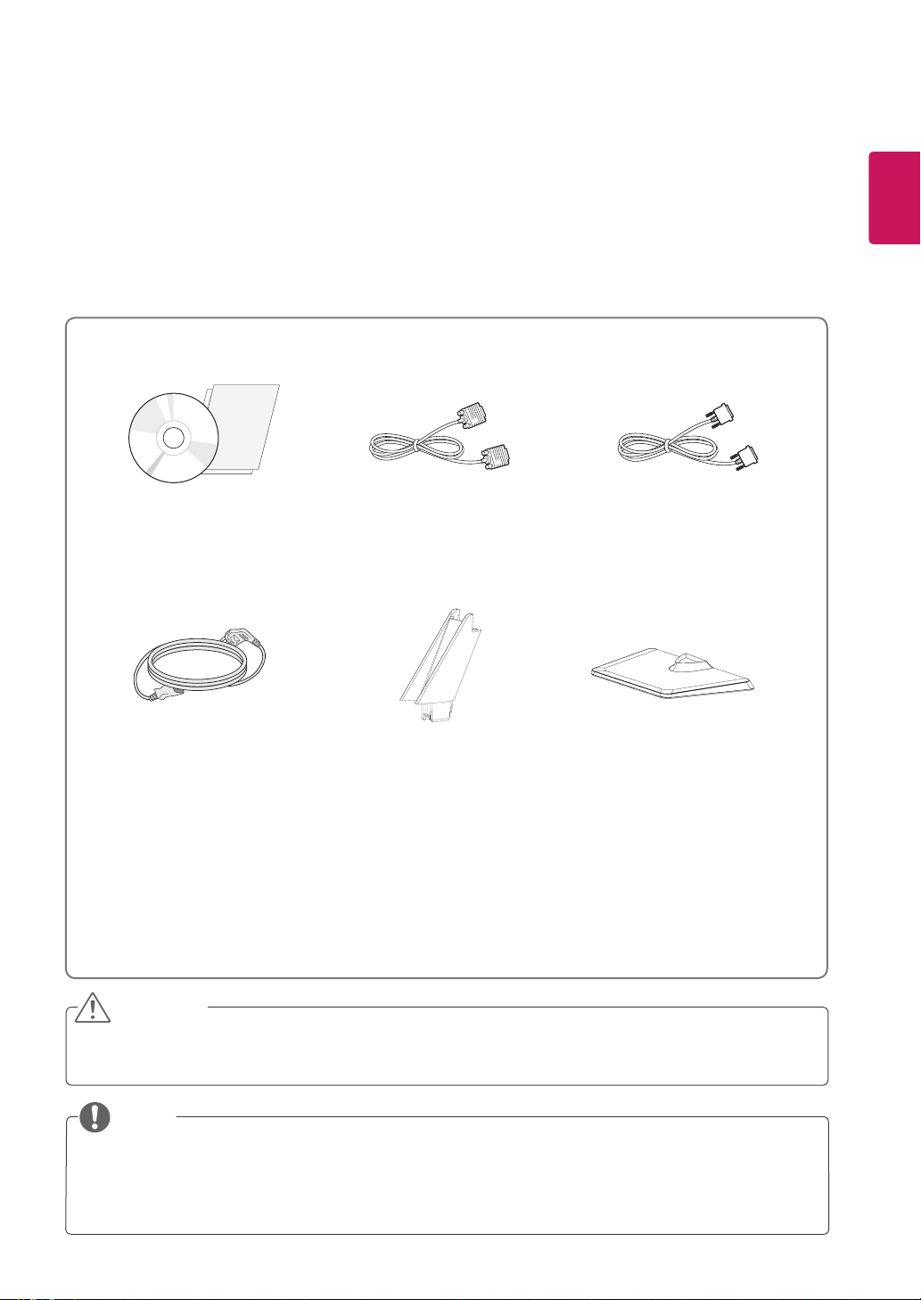
Check your product box for the following items. If there are any missing accessories, contact the local
dealer where you purchased your product. The illustrations in this manual may differ from the actual product
and accessories.
CD(Owner's Manual) /
Card
D-SUB Cable
(This cable is not included in all
countries.)
(This cable is not included in all
DVI-D Cable
countries.)
ENGLISH
ENG
Power Cord
Stand Body
Stand Base
CAUTION
Do not use any unapproved accessories to ensure the safety and product life span.
y
Any damages or injuries by using unapproved accessories are not covered by the warranty.
y
NOTE
The accessories supplied with your product may vary depending on the model.
y
Product specifications or contents in this manual may be changed without prior notice due to upgrade
y
of product functions.
ENGLISH
ENG
ASSEMBLING AND PREPARING
4
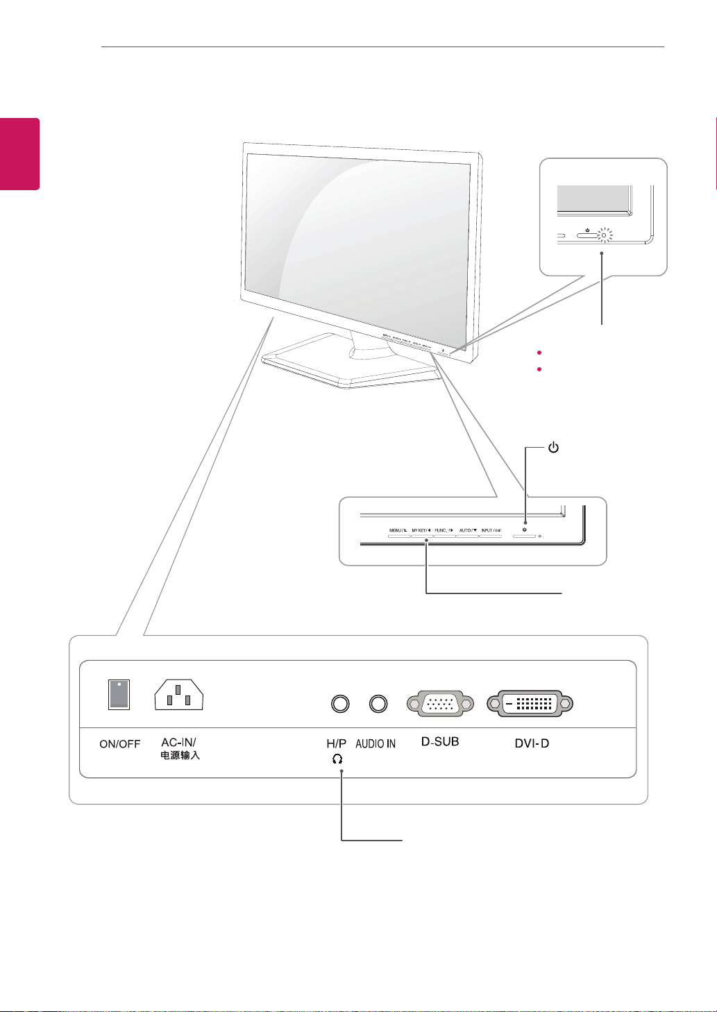
Parts and buttons
Power Indicator
LED On : Power is on
LED Off: Power is off
(Power Button)
Front Side Buttons
Input Connectors (See p.11 to 13)See p.11 to 13) to 13)13))
5
ENG
ENGLISH
ASSEMBLING AND PREPARING
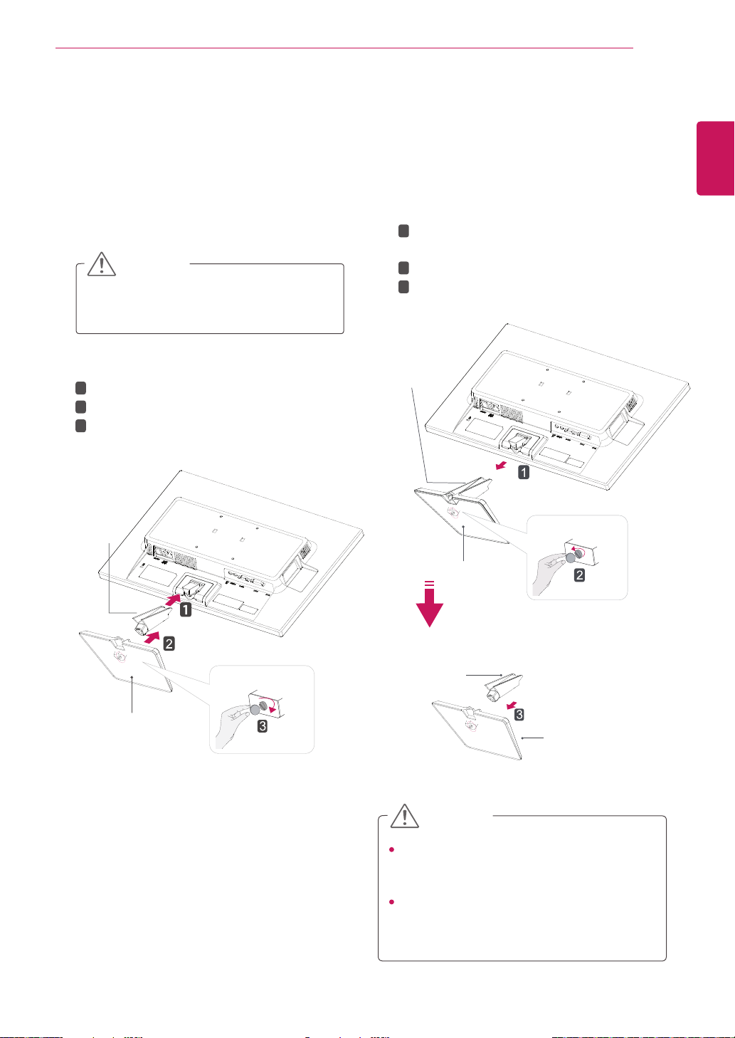
Attach the Stand Body to the monitor set.
Attach the Stand Base.
Tighten the screw to the right with a coin.
Setting up the Monitor set
Attaching the Stand Base
1
Place the Monitor set with the screen side
down on a flat and cushioned surface.
Lay a foam mat or soft protective cloth
on the surface to protect the screen from
damage.
CAUTION
2
Stand Base
Stand Body
1
2
3
This illustration depicts the general model of
connection. Your monitor may differ from the
items shown in the picture.
Do not carry the product upside down holding
only the stand base. The product may fall
and get damaged or injure your foot.
CAUTION
Detaching the Stand Base
1
Place the Monitor set with the screen side
down on a flat and cushioned surface.
2
Stand Base
Stand Base
Stand Body
Stand Body
Pull out the Stand Body and Stand Base
from the monitor set.
Turn the screw to the left with a coin.
Pull out the Stand Base.
1
2
3
ASSEMBLING AND PREPARING
6
ENGLISH
ENG
2
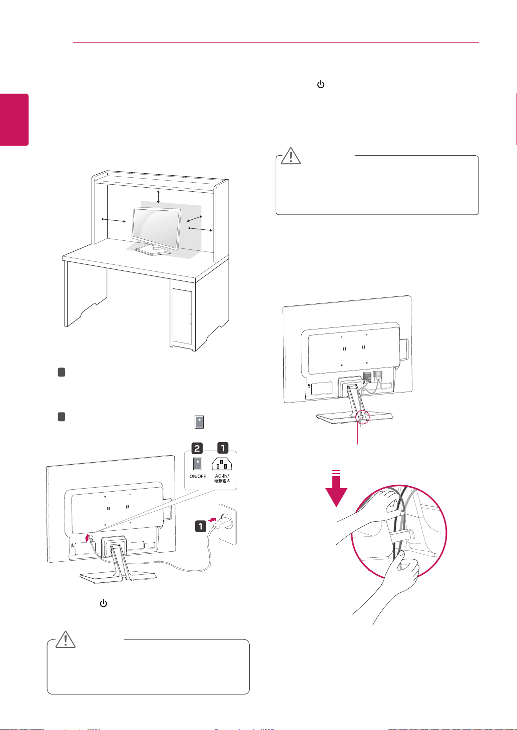
Mounting on a table
Lift and tilt the Monitor set into its upright
1
position on a table.
Leave a 10 cm (minimum) space from the wall
for proper ventilation.
10 cm
10 cm
10 cm
Connect the Power cord to the monitor, then
1
plug the power cord into the wall outlet.
(Before connect please check the “ON/OFF”
knob in “O” state).
2
Press the “ON/OFF” knob in “ ” state
(Open the power).
10 cm
Press (Power) button on the bottom switch
3
panel to turn the power on.
CAUTION
Unplug the power cord before moving the
Monitor to another location. Otherwise electric
shock may occur.
Using the cable holder
Press the (Power) button on the front of the
3
monitor to turn on the monitor.
CAUTION
Unplug the power cord prior to moving or
y
installing the monitor. There is risk of electric
shock.
Cable holder
ASSEMBLING AND PREPARING
7
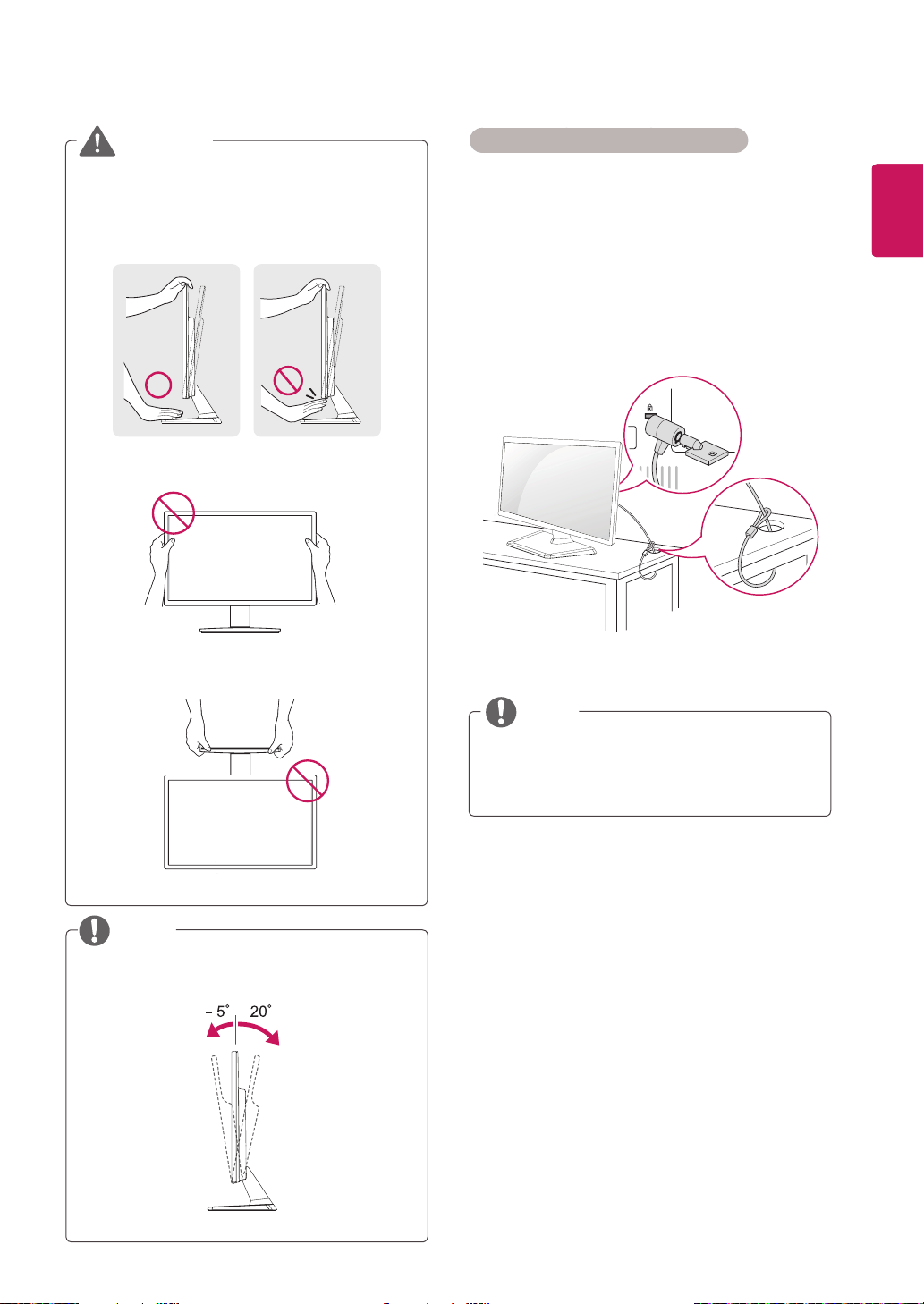
WARNING
When you adjust the angle, do not hold the
bottom of the Monitor set frame as shown on
the following illustration, as may injure your
fingers.
Do not touch or press the screen when
adjusting the angle of the monitor.
Do not hold this set like below picture.Monitor
screen can detach from stand base and injure
your body.
Using the Kensington security system
The Kensington security system connector is
located at the back of the Monitor set. For more
information of installation and using, refer to the
manual supplied with the Kensington security
system or visit
Connect the Kensington security system cable
between the Monitor set and a table.
http://www.kensington.com
.
NOTE
ENGLISH
ENG
NOTE
Tilt from +20 to -5 degrees up or down to adjust
the angle of the Monitor set to suit your view.
Front Rear
The Kensington security system is optional.
You can obtain it from most electronics stores.
ASSEMBLING AND PREPARING
10
ENGLISH
ENG
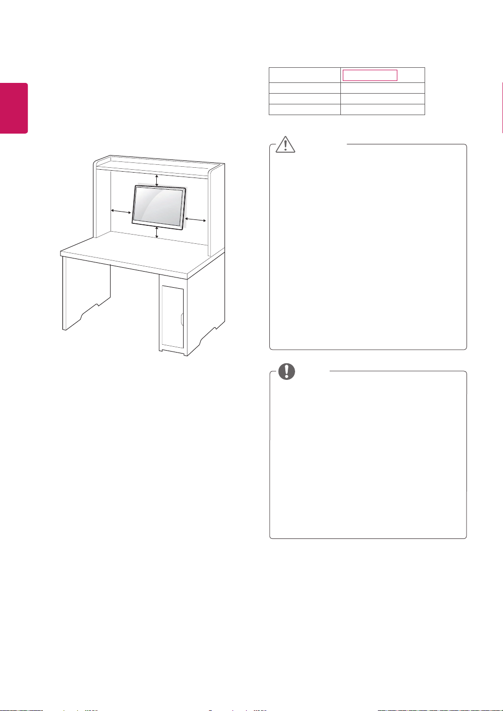
Mounting on a wall
For proper ventilation, allow a clearance of 10 cm
on each side and from the wall. Detailed
instructions are available from your dealer, see the
optional Tilt Wall Mounting Bracket Installation and
Setup Guide.
10 cm
10 cm
10 cm
10 cm
Model
VESA (A x B)
Standard screw
Number of screws
22EB23TM
100 x 100
M4
4
CAUTION
Disconnect the power cord first, and then
y
move or install the Monitor set. Otherwise
electric shock may occur.
If you install the Monitor set on a ceiling or
y
slanted wall, it may fall and result in severe
injury.
Use only an authorized LG wall mount
y
and contact the local dealer or qualified
personnel.
Do not over tighten the screws as this may
y
cause damage to the Monitor set and void
your warranty.
Use only screws and wall mounts that
y
meet the VESA standard. Any damages
or injuries by misuse or using an improper
accessory are not covered by the warranty.
If you intend to mount the Monitor set to a wall,
attach Wall mounting interface (optional parts) to
the back of the set.
When you install the Monitor set using a wall
mounting interface (optional parts), attach it
carefully so it will not drop.
Please, Use the screw and wall mount interface
1
in accordance with VESA Standards.
If you use screw longer than standard, the
2
monitor might be damaged internally.
If you use improper screw, the product might be
3
damaged and drop from mounted position. In
this case, LG Electronics is not responsible for
it.
VESA compatible.
4
Please use VESA standard as below.
5
784.8 mm (30.9 inch) and under
y
* Wall Mount Pad Thickness : 2.6 mm
* Screw : Φ 4.0 mm x Pitch 0.7 mm x
Length 10 mm
787.4 mm (31.0 inch) and above
y
* Please use VESA standard wall mount pad
and screws.
NOTE
Use the screws that are listed on the VESA
y
standard screw specifications.
The wall mount kit will include an installation
y
manual and necessary parts.
The wall mount bracket is optional. You can
y
obtain additional accessories from your local
dealer.
The length of screws may differ depending
y
on the wall mount. Be sure to use the proper
length.
For more information, refer to the
y
instructions supplied with the wall mount.
USING THE MONITOR SET
11
USING THE MONITOR SET
Connecting to a PC
Your Monitor set supports Plug & Play*.
y
*Plug & Play: A PC recognizes a connected
device that users connect to a PC and turn
on, without device configuration or user
intervention.
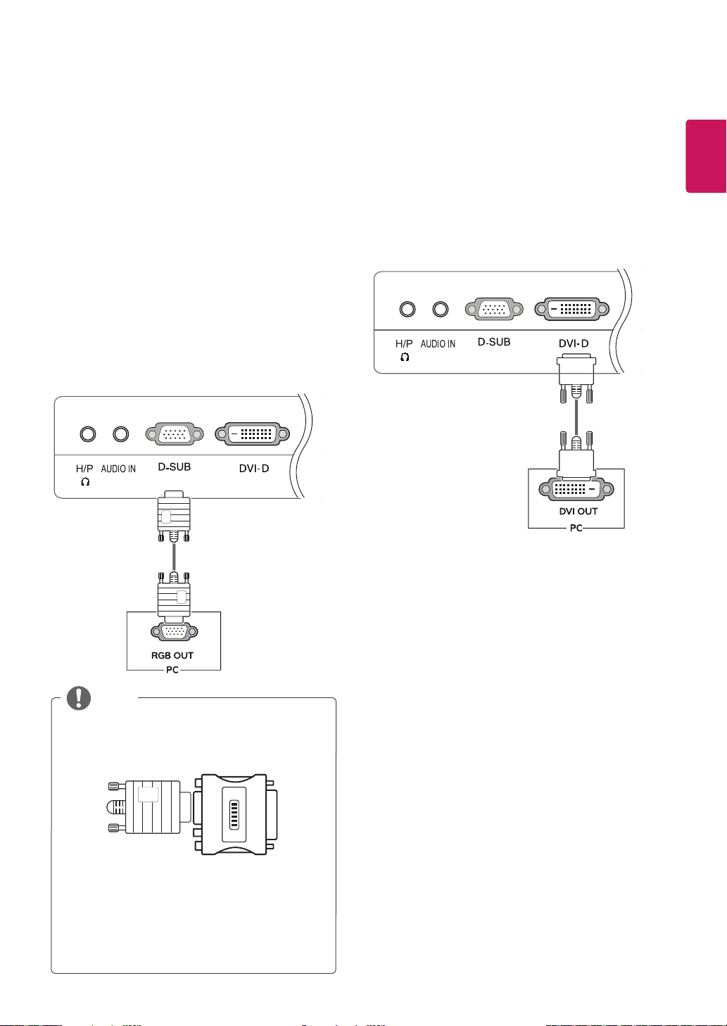
D-SUB connection
Transmits analog video from your PC to the
Monitor set. Connect the PC and the Monitor set
with the supplied D-sub 15 pin signal cable as
shown in the following illustrations.
DVI-D connection
Transmits a digital video signal from your PC to
the Monitor set. Connect the PC and the Monitor
set with a DVI cable as shown in the following
illustrations.
ENGLISH
ENG
NOTE
When using a D-Sub signal input cable
y
connector for Macintosh
Mac adapter
y
For Apple Macintosh use, a separate plug
adapter is needed to change the 15 pin
high density (3 row) D-SUB VGA connector
on the supplied cable to a 15 pin 2 row
connector.
 Loading...