

LG 21FS7RG, 21FS7RGG, 21FS7RE, 21FS7RGG-TS Service Manual
COLOR TV
SERVICE MANUAL
CAUTION
BEFORE SERVICING THE CHASSIS,
READ THE SAFETY PRECAUTIONS IN THIS MANUAL.
CHASSIS : MC-059C
MODEL : 21FS7RG/RE/RGG
21FS7RG/RE/RGG-TS
website:http://biz.LGservice.com
Nov., 2007
Printed in ChinaP/NO : 38289S0050K
Internal Use Only

- 2 -
CONTENTS
CONTENTS............................................................................................... 2
SAFETY PRECAUTIONS...........................................................................3
DESCRIPTION OF CONTROLS................................................................4
SPECIFICATIONS......................................................................................6
ADJUSTMENT ...........................................................................................8
PRINTED CIRCUIT BOARD ....................................................................15
TROUBLE SHOOTING ............................................................................17
BLOCK DIAGRAM...................................................................................21
EXPLODED VIEW....................................................................................22
EXPLODED VIEW PARTS LIST..............................................................23
REPLACEMENT PARTS LIST................................................................ 24
Copyright©2007 LG Electronics.Inc. All right reserved.
Only for training and service purposes.
LGE Internal Use Only
- 3 -
SAFETY PRECAUTIONS
Many electrical and mechanical parts in this chassis have special safety-related characteristics. These parts are identified by in the
Schematic Diagram and Replacement Parts List.
It is essential that these special safety parts should be replaced with the same components as recommended in this manual to prevent
X-RADIATION, Shock, Fire, or other Hazards.
Do not modify the original design without permission of manufacturer.
General Guidance
An isolation Transformer should always be used during the
servicing of a receiver whose chassis is not isolated from the AC
power line. Use a transformer of adequate power rating as this
protects the technician from accidents resulting in personal injury
from electrical shocks.
It will also protect the receiver and it's components from being
damaged by accidental shorts of the circuitry that may be
inadvertently introduced during the service operation.
If any fuse (or Fusible Resistor) in this TV receiver is blown,
replace it with the specified.
When replacing a high wattage resistor (Oxide Metal Film Resistor,
over 1W), keep the resistor 10mm away from PCB.
Keep wires away from high voltage or high temperature parts.
Due to high vacuum and large surface area of picture tube,
extreme care should be used in handling the Picture Tube. Do
not lift the Picture tube by it's Neck.
X-RAY Radiation
Warning:
To determine the presence of high voltage, use an accurate high
impedance HV meter.
Adjust brightness, color, contrast controls to minimum.
Measure the high voltage.
The meter reading should indicate
23.5 ± 1.5KV: 14-19 inch, 26 ± 1.5KV: 19-21 inch,
29.0 ± 1.5KV: 25-29 inch, 30.0 ± 1.5KV: 32 inch
If the meter indication is out of tolerance, immediate service and
correction is required to prevent the possibility of premature
component failure.
Before returning the receiver to the customer,
always perform an AC leakage current check on the exposed
metallic parts of the cabinet, such as antennas, terminals, etc., to
be sure the set is safe to operate without damage of electrical
shock.
Leakage Current Cold Check(Antenna Cold Check)
With the instrument AC plug removed from AC source, connect an
electrical jumper across the two AC plug prongs. Place the AC
switch in the on position, connect one lead of ohm-meter to the AC
plug prongs tied together and touch other ohm-meter lead in turn to
each exposed metallic parts such as antenna terminals, phone
jacks, etc.
If the exposed metallic part has a return path to the chassis, the
measured resistance should be between 1MΩ and 5.2MΩ.
When the exposed metal has no return path to the chassis the
reading must be infinite.
An other abnormality exists that must be corrected before the
receiver is returned to the customer.
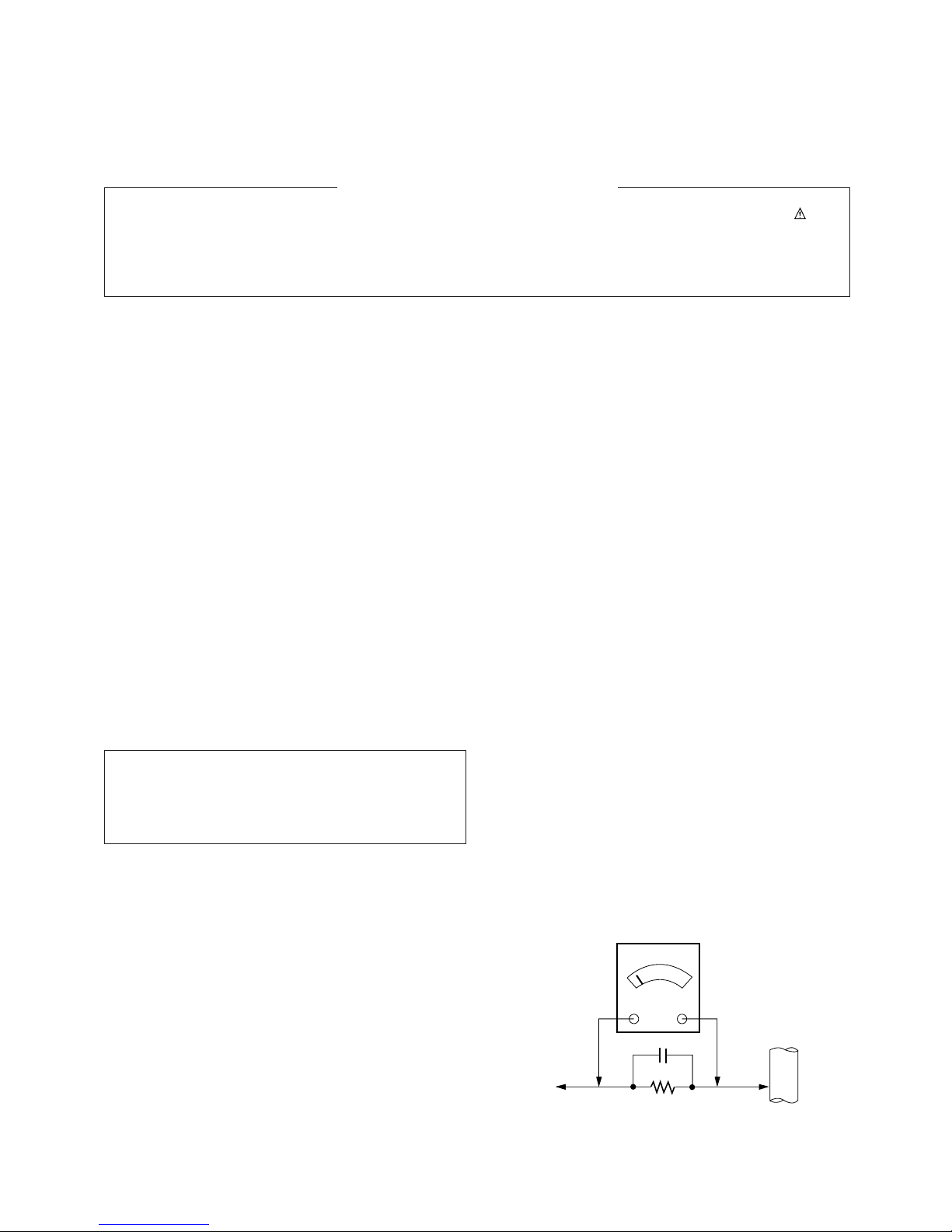
Leakage Current Hot Check (See below Figure)
Plug the AC cord directly into the AC outlet.
Do not use a line Isolation Transformer during this check.
Connect 1.5K/10watt resistor in parallel with a 0.15uF capacitor
between a known good earth ground (Water Pipe, Conduit, etc.)
and the exposed metallic parts.
Measure the AC voltage across the resistor using AC voltmeter
with 1000 ohms/volt or more sensitivity.
Reverse plug the AC cord into the AC outlet and repeat AC voltage
measurements for each exposed metallic part. Any voltage
measured must not exceed 0.75 volt RMS which is corresponds to
0.5mA.
In case any measurement is out of the limits specified, there is
possibility of shock hazard and the set must be checked and
repaired before it is returned to the customer.
Leakage Current Hot Check circuit
The source of X-RAY RADIATION in this TV receiver is the High
Voltage Section and the Picture Tube.
For continued X-RAY RADIATION protection, the replacement
tube must be the same type tube as specified in the
Replacement Parts List.
1.5 Kohm/10W
To Instrument’s
exposed
METALLIC PARTS
Good Earth Ground
such as WATER PIPE,
CONDUIT etc.
AC Volt-meter
IMPORTANT SAFETY NOTICE
0.15uF
Copyright©2007 LG Electronics.Inc. All right reserved.
Only for training and service purposes.
LGE Internal Use Only
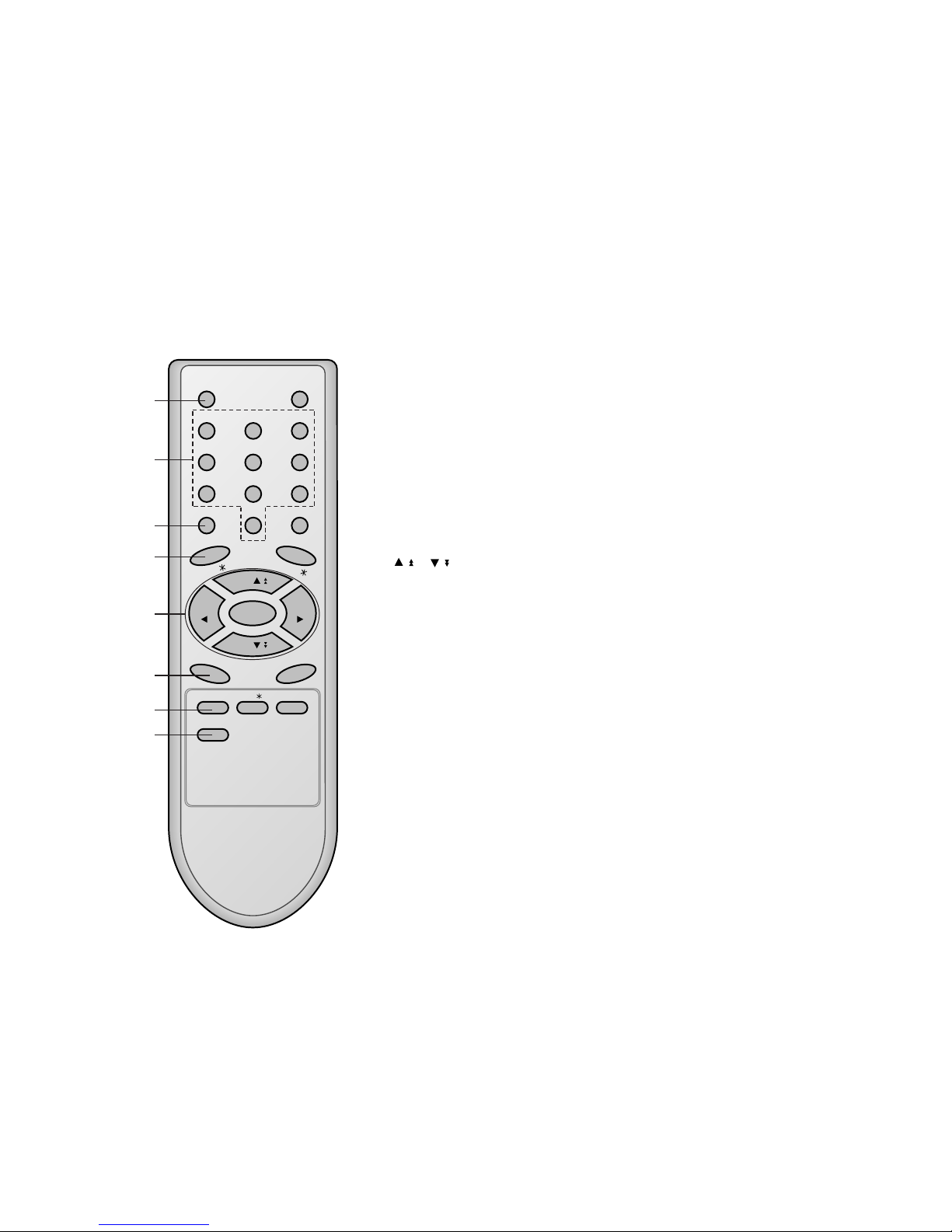
All the functions can be controlled with the remote control handset.
Some functions can also be adjusted with the buttons on the front
panel of the set.
Remote control handset
Before you use the remote control handset, please install the batteries. See the next page.
1. POWER
switches the set on from standby or off to standby.
2. NUMBER BUTTONS
switches the set on from standby or directly select a number.
3. MENU
selects a menu.
4. EYE/*(option)
switches the eye function on or off.
5.
/
(Programme Up/Down)
selects a programme or a menu item.
switches the set on from standby.
scans programmes automatically.
F / G
(Volume Up/Down)
adjusts the volume.
adjusts menu settings.
OK
accepts your selection or displays the current mode.
6. Q.VIEW
returns to the previously viewed programme.
7. PSM (Picture Status Memory)
recalls your preferred picture setting.
8. FAVOURITE
selects a favorite programme.
( )
( )
POWER MUTE
123
456
789
MENU
TV/AV
0
EYE/
Q.VIEW
LIST
I / II /
( )
PR
( )
PR
OK
VOLVOL
PSM SSM/ SLEEP
FAVOURITE
1
2
3
4
5
6
7
8
- 4 -
DESCRIPTION OF CONTROLS
Copyright©2007 LG Electronics.Inc. All right reserved.
Only for training and service purposes.
LGE Internal Use Only

- 5 -
9. MUTE
switches the sound on or off.
10. TV/AV
selects TV or AV mode.
switches the set on from standby.
11. I/II/*(option)
selects the language during dual language broadcast. (option)
selects the sound output.
12. LIST
displays the programme table.
13. SLEEP
sets the sleep timer.
14. SSM/*(Sound Status Memory) (option)
recalls your preferred sound setting.
COLOURED BUTTONS : These buttons are used for teletext (only
TELETEXT models) or programme edit.
POWER MUTE
1 2 3
4 5 6
7 8 9
MENU
TV/AV
0
EYE/
Q.VIEW
LIST
I / II /
( )
PR
( )
PR
OK
VOLVOL
PSM SSM/ SLEEP
FAVOURITE
9
10
11
12
13
14
Copyright©2007 LG Electronics.Inc. All right reserved.
Only for training and service purposes.
LGE Internal Use Only
V Scope
This specification is applied to all the television related to MC059C Chassis.
V Requirement for Test
Each part is tested as below without special appointment.
1) Temperature : 25 ± 5°C (77 ± 9°F), CST : 40 ± 5
(CST must be tested 40
± 5°C . Humidity : 50%)
2) Relative Humidity : 65
± 10%
3) Power Voltage : Standard input Voltage (AC110-240V~,
50/60Hz)
* Standard Voltage of each products is marked by models.
4) Specification and performance of each parts are followed
each drawing and specification by part number in
accordance with BOM.
5) The receiver must be operated for about 20 minutes prior to
the adjustment.
V Test Method
1) Performance : LGE TV test method followed.
2) Demanded other specification
- CCC
- Safety : K60065
- 6 -
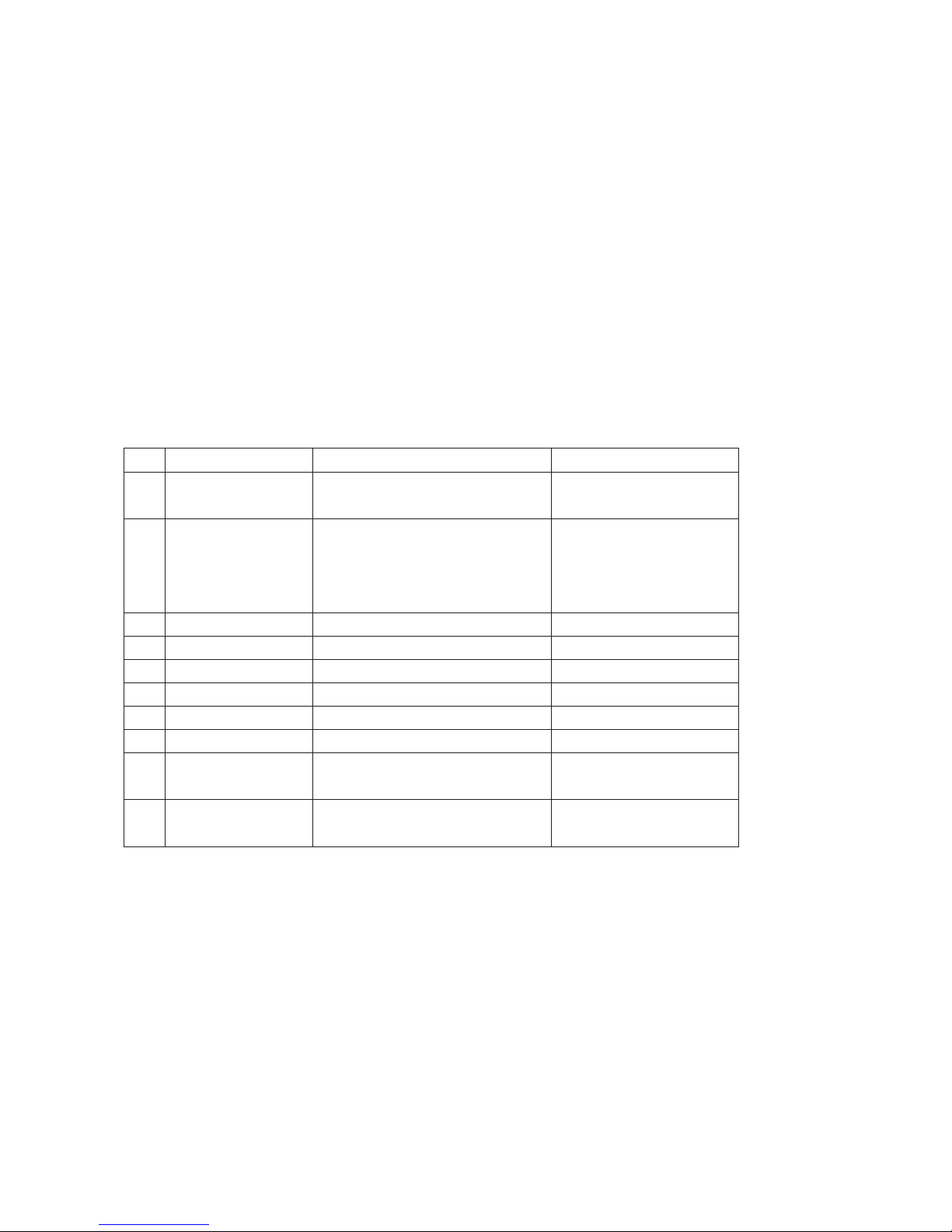
A General specification
SPECIFICATIONS
Note : Specification and others are subject to change without notice for improvement.
Item
Receiving System
Available Channel
Input Voltage
Market
Screen Size
Aspect Ratio
Display Method
Tuning System
Operating Environment
Storage Environment
Specification
PAL BG, DK, I / NTSC M (AV 3.58/ 4.43)
SECAM DK
VHF : E2 ~ E12
UHF : E21 ~ E69
CATV : S1 ~ S20
HYPER : S21 ~ S41
AC100 - 240V~, 50/60Hz
China, Indonesia, Thai, Vietnam, CIS
14 ~ 21inch (FLAT / Conventional)
4:3
CRT
FVS
Temp : 0 ~ 40 deg
Humidity : ~ 85 %
Temp : -20 ~ 60 deg
Humidity : ~ 90 %
Remark
China/ Indonesia/ Thai/ Vietnam
CIS
No.
1
2
3
4
5
6
7
8
9
10
Copyright©2007 LG Electronics.Inc. All right reserved.
Only for training and service purposes.
LGE Internal Use Only
- 7 -
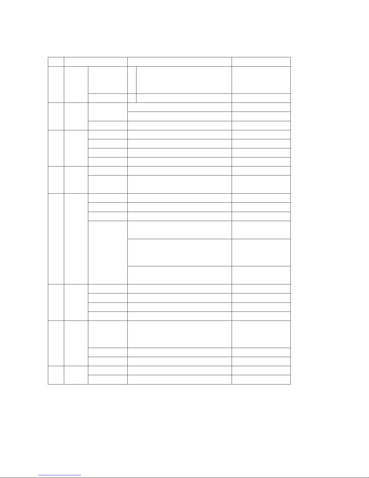
A Features and Function
Item
Feature AV Input
AV Output
Component
Earphone
Key Local Key
Remocon
Channel Auto prog.
Manual
Prog. edit
Favorite
Picture PSM
User Control
Sound SSM
Treble/ Bass
Equalizer
FM Transmitter
Timer Clock
Off time
On time
Auto off
Special Language
Input
Child lock
Etc. Sleep
Review
Specification
2 AV 1, 2
1 Monitor out
Input(For component)
1 Front
Power, Vol(
F, G), PR(E, D), MENU, OK
Turbo-Picture, Sound
LG Code (NEC)
System/ Storage/ Normal/ Turbo
Storage/ System/ Channel/ Fine/ Search/ Name
Copy/ Move/ Delete/ Skip
8 Channel
Dynamic/ Standard/ Mild/ Game/ User
Contrast/ Brightness/ Color/ Sharpness
Tint (NTSC-M Only)
Flat/ Music/ Movie/ Speech/ User
0 ~ 100
100/ 400/ 1K/ 4K/ 10K
Low Band(7ch)
87.7/ 87.9/ 88.1/ 88.3/ 88.5/ 88.7/ 88.9(MHz)
High Band(7ch)
106.7/ 106.9/ 107.1/ 107.3/ 107.5/ 107.7/
107.9(MHz)
Wide Range(1091ch)
88.0 ~ 107.0MHz
-- : --
-- : -- Off(On)
-- : -- Pr 1 VOL 30 Off(On)
On/ Off
Chinese/ English
English/ Russia
English/ Indonesia/ Thai/ Vietnam
TV/ AV1/ AV2/ Component
On/ Off
Remark
Rear1, Front1(CVBS,L,R)
Rear
Rear(Y,Pb,Pr,DVD-L/R)
7EA/ Front
Option
AV, RF Stereo Option
AV Stereo
RF Stereo
China
CIS
East-Asia
No.
1
2
3
4
5
6
7
8
Copyright©2007 LG Electronics.Inc. All right reserved.
Only for training and service purposes.
LGE Internal Use Only
1. Scope of Application
These instructions are applied to MC-059C Chassis.
2. Notes
1) Because this is a cold chassis, it is not necessary to use an
isolation transformer. However, operating it using a
transformer between the power supply line and chassis input
to prevent electric shock and to protect the test instrument.
2) All adjustment must be done in the correct sequence.
However, for better productivity, it can be change in a prepermitted range.
3) Environment conditions : If not specified, it must be done in
following conditions.
Temperature : 25 ± 5°C
Humidity 60% ± 10%
4) Power supply of SET : AC100-240~ ± 10%, 50/60Hz
5) If not specified, the receiver must be operated for more than
20 minutes prior to the adjustment.
6) Signal : Received the standard color signal (65±1dBuV).
- NTSC
: LG standard signal means the digital pattern 13CH(480NC)
- PAL/SECAM
: LG standard signal means the digital pattern PAL-B/G 05CH
7) If not specified, APC ON is APC CLEAR(DYNAMIC)
3. AGC Voltage Adjustment
3-1. Necessary Instrument
: Digital Multi-meter-1 set
- Max Input Current : Over 1A/ Max Input Voltage : 500Vdc
- Measurement Range : 10mV-100mVdc/ Accuracy : 0.03%
3-2. Adjustment Preparation
1) Input in the 75Ω cable 65dB(±1dB) LG standard signal.
2) Connect the multi-meter to J105(AGC Check, Marking).
3-3. Adjustment
1) Press the “INSTART” key of factory remote control and
select “VP0 (RFAGC)” adjustment mode.
2) Press the VOL+/-(
F/ G) key until the multi-meter shows
reading as shown below.
3) CAUTION
: Since the signal strength can be easily changed by the
condition of signal cable, you need to check the signal
strength frequently in order to prevent error.
4. Screen Voltage Adjustment
4-1. Adjustment of Screen Manually
(Using SVC Remote Control)
1) Input in the 75ohm cable LG standard signal(Digital Pattern,
480NC).
2) Press the “ADJ’ key of factory remote control once to make
the TV set display.
3) Turn the screen volume on the FBT clockwise until the
horizontal line is visible and turn it counterclockwise until
horizontal line faintly visible.
(Exit screen voltage adjustment by press “Enter(
A)” key of
factory remote control.)
5. Purity and Convergence Adjustment
5-1. Purity adjustment
(1) Adjustment Preparation
1) Receive Red Raster Pattern for purity adjustment(51CH).
2) Demagnetize the CPT and Cabinet with a degaussing coil.
(2) Adjustment
1) Pre-adjust the static convergence (STC) with the 4 and
6pole magnet.
2) If the horizontal Line is inline with CPT Mark, 2-Pole
magnet should direct 3-9 o’clock direction.
3) If not, direct 2-pole magnet handle toward 6-12 o’clock
direction and adjust the Horizontal Line to fall onto the
mark opening the magnet at an angle.
4) Push the DY(deflection yoke) all the way to the CPT
funnel.
5) Turn the purity magnet(2-pole magnet) so that the “green”
color portion of left side and the “blue” color portion on the
right side have equal amount of color.
6) Pull the DY slowly backward and fix it when the whole
screen becomes red.
(The specified torque for fixing DY screw should be
10Kg/cm.)
5-2. Convergency Adjustment
(1) Necessary Instrument
1) Degaussing Coil
2) Convergency fixing instrument
(2) Preliminary steps
1) Operate the unit at the least 30minutes before adjustment.
2) Using degaussing coil, remove the stains on CPT &
Cabinet.
3) Received the Cross Hatch Pattern of Convergence.(09ch)
4) Let the Contrast in normal luminance level
.
G R B
- 8 -
ADJUSTMENT
G R B
R
G R B
6700VS0002F
6700PF0002F
6700MF0014A
6700MF0014B
LGIT
SANYO
LGIT
LGIT
3.0 ± 0.05V
2.3 ± 0.05V
2.3 ± 0.05V
2.15 ± 0.05V
70dBu
65dBu
65dBu
65dBu
TAEW-G002D
115-B-A86EL
TAEW-G013D
TAEW-G017D CIS
Tuner P/N Maker AGC Vol Signal Tuner Spec. Remark
Copyright©2007 LG Electronics.Inc. All right reserved.
Only for training and service purposes.
LGE Internal Use Only
- 9 -
(3) Static Convergence (STC) Adjustment
1) Receive the Cross Hatch Pattern Convergence(09ch).
2) Before adjusting Static Convergence(STC), adjust the
focus first seeing to it that the WHITE color picture quality
is sharp enough.
3) Converge the RED vertical and BLUE vertical line in
unity(same line) by changing the angle between the 2
tabs of 4-pole magnet.
4) Converge the RED horizontal and BLUE horizontal line in
unity(same line) by turning the 2 tabs of the 4-pole
magnet. At this time, do not change the angle between
the 2 tabs.
5) Converge the R, G, B vertical line in unity(same line) by
changing the angle between the 2 tabs of the 6-pole
magnet.
6) Converge the R, G, B horizontal line in unity(same line) by
turning the 2 tabs of the 6-pole magnet. At this time, do
not change the angle between the 2 tabs.
(4) Dynamic Convergence (DYC) Adjustment
1) Y-axis Adjustment
: Adjust convergence of Y-axis(vertical) by moving the
deflection yoke(DY) left and right.
2) X-axis Adjustment
: Adjust convergence of X-axis(horizontal) by moving the
deflection yoke(DY) up and down.
6. White Balance Adjustment
6-1. Necessary Instrument
1) Automatic White Balance Meter(Low/High light Pattern
generator)
2) White Balance meter(CRT Color Analyzer, CA-100) :1set
3) Factory Remote Control
6-2. Adjustment Preparation
: Prior to this adjustment, the Screen Voltage adjustment
should be finished.
6-3. Automatic adjustment
1) Adjust the using Auto White Balance Meter.
2) Enter CPU OFF Mode by pressing “IN-START” & “MUTE”
key of factor remote control in turn before adjustment.
Exit CPU OFF mode by press the “TV/AV” key of factory
remote control after adjustment finished.
* In case there is excess RED color at screen voltage
adjustment, adjust it using “volume - (
F) key of factory remote
control until the RED color disappear.
6-4. Manual adjustment
1) Adjust using white Balance meter and factory remote
control.
2) Enter white balance adjustment mode by pressing
“INSTART” key
3) Use the CH
D, CHE Key to choose adjustment item.
4) Use the VOL
F, VOLG Key to change item data.
5) Adjustment Procedure
a. Make the picture luminance 45Ft-L by changing the
“CONTRAST” and “BRIGHTNESS”.
b. Adjust X data of High light with R-DRIVE(VP7) and Y
data with B-DRIVE(VP9) to have the color temperature
as shown below.
c. Make the picture luminance 4.5Ft-L by changing the
“CONTRAST” and “BRIGHTNESS”.
d. Adjust X data of low light with R-BIAS(VP4) and Y data
with B-BIAS(VP6) to have the color temperature as
shown below.
e. Repeat steps a~d until both low and high light have
same readings as shown below.
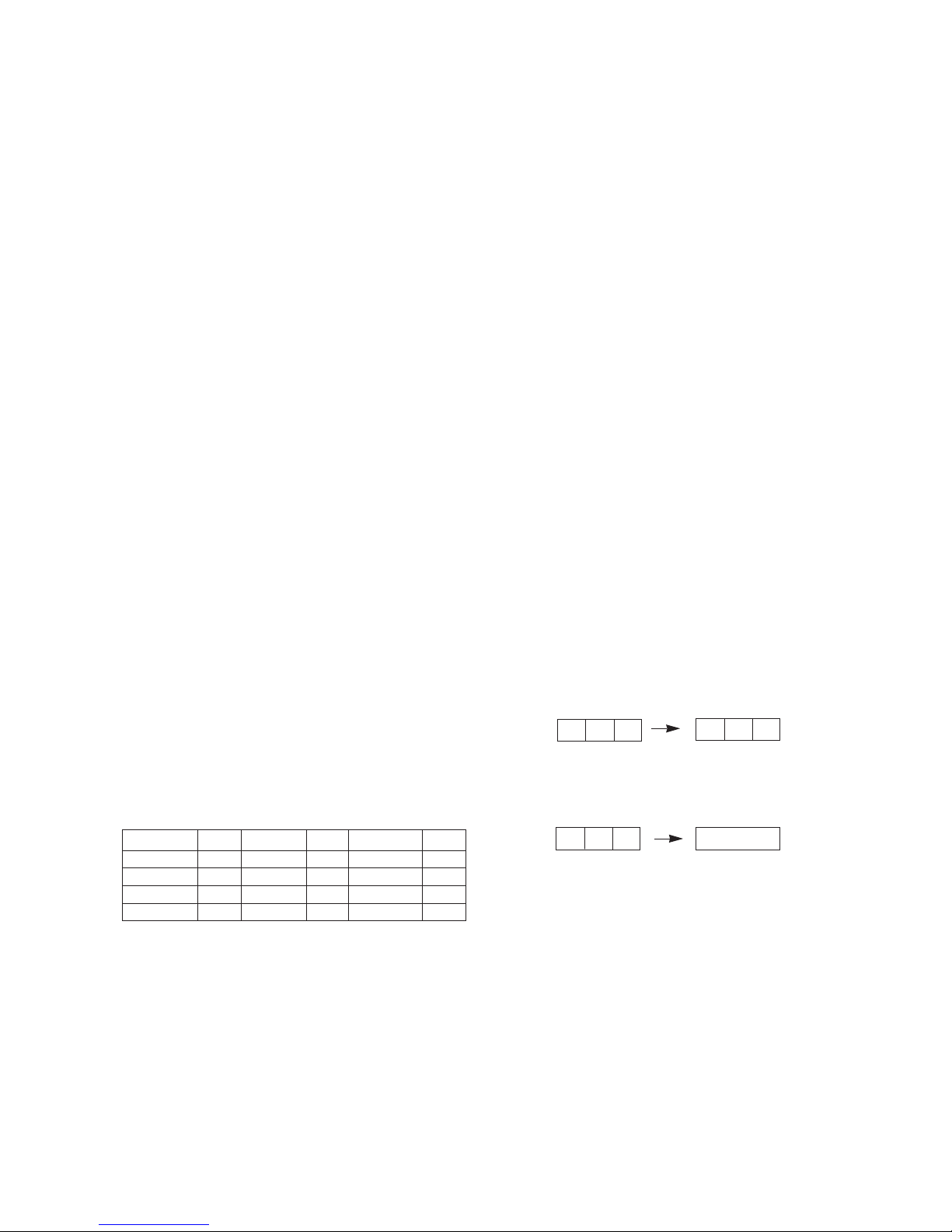
7. Focus Voltage Adjustment
This adjustment must be done after operating the TV set
receiver sufficiently.
7-1. Adjustment Preparation
1) Receive Digital pattern and Set the picture condition on
“APC ON”(CLEAR) mode.
7-2. Adjustment
Turn the focus volume on the FBT upper direction th have
the best focus vertical line(figure 1.(a)) and horizontal line
(figure 1(b)) as shown below.
8. SUB-BRIGHTNESS Adjustment
This adjustment must be done after White balance adjustment.
8-1. Adjustment Preparation
1) Receive the LG standard Mono scope pattern(CH14).
2) Set the picture condition on “APC ON”(CLEAR) mode.
8-2. Adjustment
1) Press the “ADJ”key of the factory remote control twice to
enter to “SUB-BRIGHTNESS” adjustment mode.
2) Change the Sub-Brightness data by pressing the VOL
F,
VOL
G key so that the number 1 in gray scale of mono
scope pattern almost disappear.(See figure 2)
8-3. Sub-Tint adjustment
This adjustment has to be done only if the picture has bad tint
otherwise, it can be omitted if the picture has good tint.
1) Receive LG standard pattern signal(SMPTE, 2CH)
2) Set the picture condition on “APC ON”(CLEAR) mode.
Market Color Temperature X-AXIS Y-AXIS
PAL/SECAM 12,000±800 0.270±0.003 0.283±0.003
<Fig. 1>
<Fig. 2> MONO SCOPE Pattern signal
0 1 2 3 4 5 6 7 8 9
Gray Scale
Color Bar
Copyright©2007 LG Electronics.Inc. All right reserved.
Only for training and service purposes.
LGE Internal Use Only

- 10 -
3) Press the “ADJ” key of the factory remote control three
times to enter to “SUB-TINT” adjustment mode.
4) Change the Sub-Tint data by pressing the VOL
F, VOLG
key until the upper and lower CYAN color becomes same
color.
9. Deflection setting data adjustment
These adjustment will be done by automatic adjustment
Equipment.
For manual adjustment, it is also possible by the following
procedure.
9-1. Adjustment Preparation
1) Deflection setting data adjustment can be done only with
remote control.
2) Press “IN-START” key on factory remote control continuously
to enter to Deflection Adjustment mode.
3) Press the CH
D, E key to select adjustment item.
4) Press the VOL
F, G key to change the data.
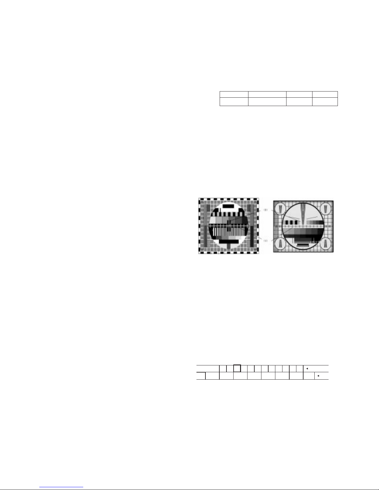
9-2. Adjustment
1) Horizontal Position Adjustment
Select VP1(H-POS) and adjust so that the left and right
vertical line are symmetrical as possible.
2) Vertical Position Adjustment
Select VP2(V-POS) and adjust so that the horizontal center
line coincide with geometric horizontal center of the CPT.
3) Vertical Size Adjustment
Select VP3(V-SIZE) and so that the middle circle of the
Digital Pattern(480NC, 13CH) coincide with the effective
screen of CPT
4) H-SIZE
Adjustment of the H-size is not basically done but if the Hsize is inappropriate, the H-size is adjustable by adjusting
variable resistance(VR403) of the main assy.
-> Adjustment for the received pattern is done so that the
outer line of the left, right and the remotest grid will
correspond to the effective boundary surface. (The
remotest grid, NTSC : within 2.5 ~ 3.0 column, PAL :
within 0 ~25 %)
5) Trapezoidal
Adjust a trap by adjusting variable resistance(VR402) of the
main A’ssy.
-> Adjustment is done so that the upper horizontal width of
the received screen and the bottom horizontal width will
be same (when the screen is a trapezoid shape, adjust it
to make a right square)
6) PIN AMP.
Adjust the pin AMP by adjusting variable resistance(VR401)
of the main A’ssy.
-> Adjustment is done so that the vertical line of the remotest
grid at the left or right side of the screen will be parallel to
the vertical line of the center of screen ( or the remotest
grid of CPT)
10. IIC BUS Adjustment Data Table
: Refer to <TABLE 1>
11. Instrument setting data
(automatic adjustment)
<TABLE 2>
12. EEPROM OPTION TABLE
<TABLE 3>
Speed
1
SLave ADD
VIDEO ICBAEEPROM
A2
Delay
30
EEPROM
Sub Add
74 71 76 73
SpeedPlus
Step/Data
3 3 3 3
Sub Add
Start Bit
Stop Bit
Masking
Direction
VCD
TV PC
B(R)AMP
C
6
0
0
1
B(R)CUT
9
7
0
0
1
G(B)AMP
E
6
0
0
1
G(B)CUT
B
7
0
0
1
B AMP B CUT G AMP G CUT
OPTION 1
DVD
TURBO ME
V-CURVE
V-MUTE
EYE
NICAM DT
SND MUTE
GAME
OPTION2
TURBO
ARC
200PR
BLUEBACK
TURBO AT
A2STEREO
SHARP
DVDN 6P
OPTION3
FM TRANS
FM HIGH
NTSC
DUAL SV
SYNC KI
SND FL1
SND FL2
SWOOFER
OPTION 4
SYSTEM
SND MODE
AV
LOC KEY
COLOR T
PLL DIV
OPTION 5
FM PRE
NICAM PRE
SCART PRE
A2 FM TH
FIRST TH
ZWT TH
INITIAL
0
0
0
0
0
0
1
0
0
0
0
1
1
1
0
1
0
0
1
1
0
0
0
0
4
1
2
1
1
31
6
8
2
5
10
7
REMARK
DVD function (1:W, 0:W/O)
T-P,T-S FUNCTION DISPLAY on MENU
VOLUME CURVE (1:HIGH, 0:LOW)
VIDEO MUTE
EYE function (1:W, 0:W/O)
NICAM ID
SOUND MUTE at no signal (yes or not)
GAME function (1:Yes, 0:No)
REMARK
TURBO P/S function (1:W, 0:W/O)
ARC function (1:W, 0:W/O)
200 CH. MEMORY
BLUEBACK function (1:W, 0:W/O)
TURBO SEARCH function (1:W, 0:W/O)
A2 STEREO(WITH NICAM)
SHARPNESS DATA (1:+10, 0:NORMAL)
DVD 6P (1:W, 0:W/O)
REMARK
FM TRANS function (1:W, 0:W/O)
FM TRANS FREQUENCY (1:HIGH, 0:LOW)
NTSC function (1:W, 0:W/O)
AV ST MODE (1:PSEUDO, 0:MATRIX)
SYNC KILL function (1:W, 0:W/O)
MONO FILTER (50MHz/ 75Hz)
MONO FILTER (100Hz/ 200KHz)
WOOFER function (1:W, 0:W/O)
REMARK
0:CHINA / 1:INDONESIA / 2: THAI / 3: VIETNAM / 4MULTI
0:MONO / 1:AV ST / 2:REAL ST
0:NO AV / 1:AV1 / 2:AV1,2 / 3:AV1,2,3
0:4KEY / 1:6KEY / 2:8KEY
COLOR TABLE
PLL DATA (NTSC Tuning Level)
REMARK
FM PRESCALER
NICAM PRESCALER
SCART PRESCALER
A2 PRESCALER
MONO THRESHOLD
A2 THRESHOLD
Copyright©2007 LG Electronics.Inc. All right reserved.
Only for training and service purposes.
LGE Internal Use Only
 Loading...