

LG 21FS4RLX, 21FS4RLX-ZV Service Manual
COLOR TV
SERVICE MANUAL
CAUTION
BEFORE SERVICING THE CHASSIS,
READ THE SAFETY PRECAUTIONS IN THIS MANUAL.
CHASSIS : CW62B
MODEL: 21FS4RLX
MODEL: 21FS4RLX-ZV
website:http://biz.lgservice.com
Jan., 2007
Printed in ChinaP/NO : MFL31616401 e

- 2 -
CONTENTS
Contents ....................................................................................................2
Safety Precautions....................................................................................3
Control Descriptions ................................................................................4
Specifications............................................................................................7
Adjustment Instructions...........................................................................8
SVC Remocon.........................................................................................13
Trouble Shooting....................................................................................14
Printed circuit board...............................................................................17
Block Diagram.........................................................................................19
Exploded View.........................................................................................20
Exploded View Parts List.......................................................................21
Replacement Parts List..........................................................................22
SVC. Sheet...................................................................................................
- 3 -
SAFETY PRECAUTIONS
Many electrical and mechanical parts in this chassis have special safety-related characteristics. These parts are identified by in the
Schematic Diagram and Replacement Parts List.
It is essential that these special safety parts should be replaced with the same components as recommended in this manual to prevent
X-RADIATION, Shock, Fire, or other Hazards.
Do not modify the original design without permission of manufacturer.
General Guidance
An isolation Transformer should always be used during the
servicing of a receiver whose chassis is not isolated from the AC
power line. Use a transformer of adequate power rating as this
protects the technician from accidents resulting in personal injury
from electrical shocks.
It will also protect the receiver and it's components from being
damaged by accidental shorts of the circuitry that may be
inadvertently introduced during the service operation.
If any fuse (or Fusible Resistor) in this TV receiver is blown,
replace it with the specified.
When replacing a high wattage resistor (Oxide Metal Film Resistor,
over 1W), keep the resistor 10mm away from PCB.
Keep wires away from high voltage or high temperature parts.
Due to high vacuum and large surface area of picture tube,
extreme care should be used in handling the Picture Tube. Do not
lift the Picture tube by it's Neck.
X-RAY Radiation
Warning:
To determine the presence of high voltage, use an accurate high
impedance HV meter.
Adjust brightness, color, contrast controls to minimum.
Measure the high voltage.
The meter reading should indicate
23.5 ± 1.5KV: 14-19 inch, 26 ± 1.5KV: 19-21 inch,
29.0 ± 1.5KV: 25-29 inch, 30.0 ± 1.5KV: 32 inch
If the meter indication is out of tolerance, immediate service and
correction is required to prevent the possibility of premature
component failure.
Before returning the receiver to the customer,
always perform an AC leakage current check on the exposed
metallic parts of the cabinet, such as antennas, terminals, etc., to
be sure the set is safe to operate without damage of electrical
shock.
Leakage Current Cold Check(Antenna Cold Check)
With the instrument AC plug removed from AC source, connect an
electrical jumper across the two AC plug prongs. Place the AC
switch in the on position, connect one lead of ohm-meter to the AC
plug prongs tied together and touch other ohm-meter lead in turn to
each exposed metallic parts such as antenna terminals, phone
jacks, etc.
If the exposed metallic part has a return path to the chassis, the
measured resistance should be between 1MΩ and 5.2MΩ.
When the exposed metal has no return path to the chassis the
reading must be infinite.
An other abnormality exists that must be corrected before the
receiver is returned to the customer.
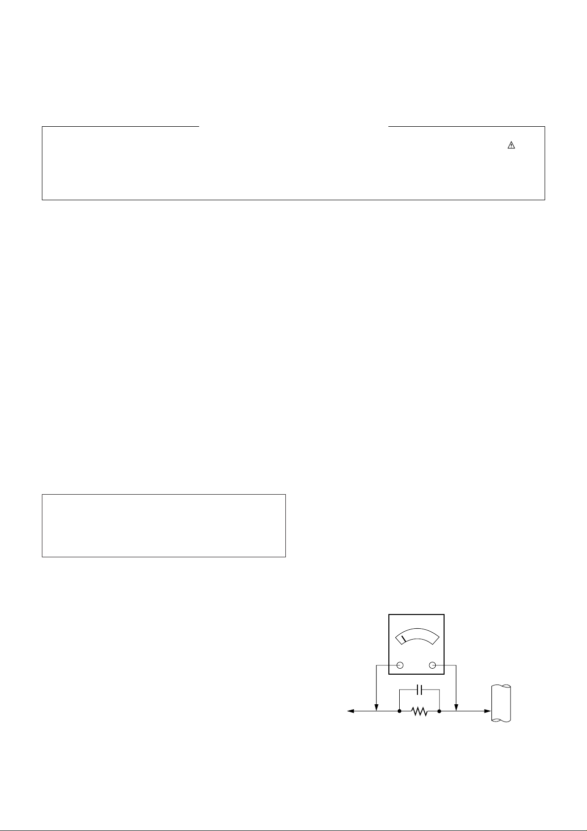
Leakage Current Hot Check (See below Figure)
Plug the AC cord directly into the AC outlet.
Do not use a line Isolation Transformer during this check.
Connect 1.5K/10watt resistor in parallel with a 0.15uF capacitor
between a known good earth ground (Water Pipe, Conduit, etc.)
and the exposed metallic parts.
Measure the AC voltage across the resistor using AC voltmeter
with 1000 ohms/volt or more sensitivity.
Reverse plug the AC cord into the AC outlet and repeat AC voltage
measurements for each exposed metallic part. Any voltage
measured must not exceed 0.75 volt RMS which is corresponds to
0.5mA.
In case any measurement is out of the limits specified, there is
possibility of shock hazard and the set must be checked and
repaired before it is returned to the customer.
Leakage Current Hot Check circuit
The source of X-RAY RADIATION in this TV receiver is the High
Voltage Section and the Picture Tube.
For continued X-RAY RADIATION protection, the replacement
tube must be the same type tube as specified in the
Replacement Parts List.
IMPORTANT SAFETY NOTICE
0.15uF
AC Volt-meter
To Instrument’s
exposed
METALLIC PARTS
Good Earth Ground
such as WATER PIPE,
CONDUIT etc.
1.5 Kohm/10W
- 4 -
DESCRIPTION OF CONTROLS
All the functions can be controlled with the remote control handset.
Some functions can also be adjusted with the buttons on the front
panel of the set.
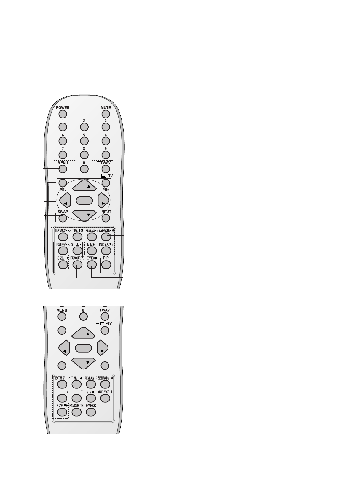
Remote control handset
Before you use the remote control handset, please install the batteries. See the next page.
1. POWER
switches the set on from standby or off to standby.
2. NUMBER BUTTONS
Switches the set on from standby or directly select a number.
3. MENU
selects a menu.
4.
D / E
(Programme Up/Down)
selects a programme or a menu item.
switches the set on from standby.
scans programmes automatically.
F / G
(Volume Up/Down)
adjusts the volume.
adjusts menu settings.
OK
accepts your selection or displays the current mode.
5. TELETEXT BUTTONS (option)
These buttons are used for teletext.
For further details, see the ‘Teletext’ section.
6.
SLEEP
sets the sleep timer.
7. PIP BUTTONS (option)
PIP
switches the sub picture on or off.
PR +/-
selects a programme for the sub picture.
SWAP
alternates between main and sub picture.
INPUT
selects the input mode for the sub picture.
SIZE
adjusts the sub picture size.
STILL
freezes motion of the sub picture.
POSITION
relocates the sub picture in clockwise direction.
(With TELETEXT / PIP)
PR
PR
OK
VOL
VOL
1
2
3
4
6
5
13
7
8
10
11
12
14
PR
PR
OK
VOL
VOL
Q.VIEW LIST
UPDATE/ HOLD/
(With TELETEXT / Without PIP)
5
9
- 5 -
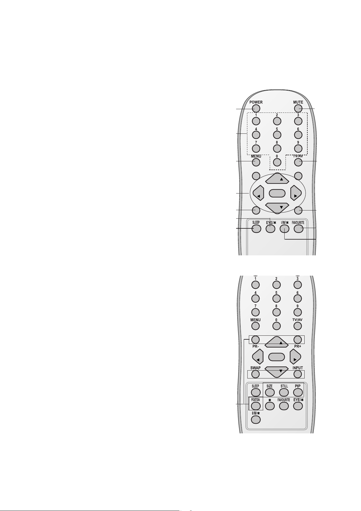
8. FAVOURITE
selects a favorite programme.
9.
EYE/*(option)
switches the eye function on or off.
10. MUTE
switches the sound on or off.
11. TV/AV
selects TV or AV mode.
switches the set on from standby.
exits the Teletext mode
(option)
.
12.
I/II/
*
selects the language during dual language broadcast.
selects the sound output (option).
13. Q.VIEW (or SWAP)
returns to the previously viewed programme.
14.
LIST (or INPUT)
displays the programme table.
*
: No function
COLOURED BUTTONS : These buttons are used for teletext (only
TELETEXT models) or programme edit.
(Without TELETEXT / PIP)
PR
PR
OK
VOL
VOL
(With PIP / Without TELETEXT)
PR
PR
OK
VOL
VOL
Q.VIEW LIST
1
2
3
4
13
6
9
10
11
8
14
7
12
- 6 -
1. MAIN POWER (ON/OFF)
switches the set on or off.
2. POWER/STANDBY INDICATOR
illuminates brightly when the set is in standby
mode.
dims when the set is switched on.
3. REMOTE CONTROL SENSOR
Note : Only use the supplied remote control
handset. (When you use others, they won’t be
able to function.)
4. MENU (option)
selects a menu.
5. OK (option)
accepts your selection or displays the current
mode.
FF / GG
(Volume Up/Down) (option)
adjusts the volume.
adjusts menu settings.
DD / EE
(Programme Up/Down) (option)
selects a programme or a menu item.
switches the set on from standby.
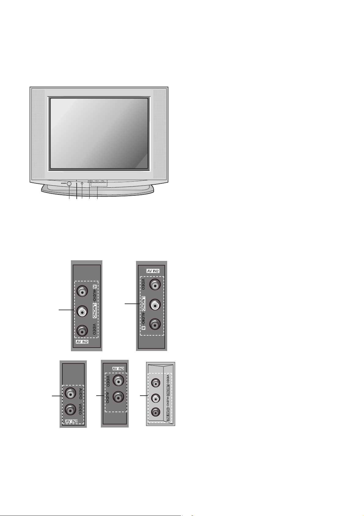
6. AUDIO (or AUDIO-L/R)/VIDEO IN SOCKETS
(AV IN2) (option)
Connect the audio/video out sockets of external
equipment to these sockets.
7. EYE (option)
adjusts picture according to the surrounding
conditions.
Note : Shown is a simplified representation of front
or side panel. What is shown here may be
somewhat different from your set or can not be
supplied on your area.
Side panel
6
6
6
6
6
1 2 3 4
5
- 7 -
SPECIFICATIONS
Note : Specification and others are subject to change without notice for improvement.
O2@@6Khe
W2@@@@@@6Xh
7@@@@@@@@1h
?J@@@@@@@@@@L?g
?7@@@@@@@@@@1?g
?@@@@@@@@@@@@?g
?@@@@@@@@@@@@?g
?3@@@@@@@@@@5?g
?N@@@@@@@@@@H?g
3@@@@@@@@5h
V4@@@@@@0Yh
I4@@0Mhe
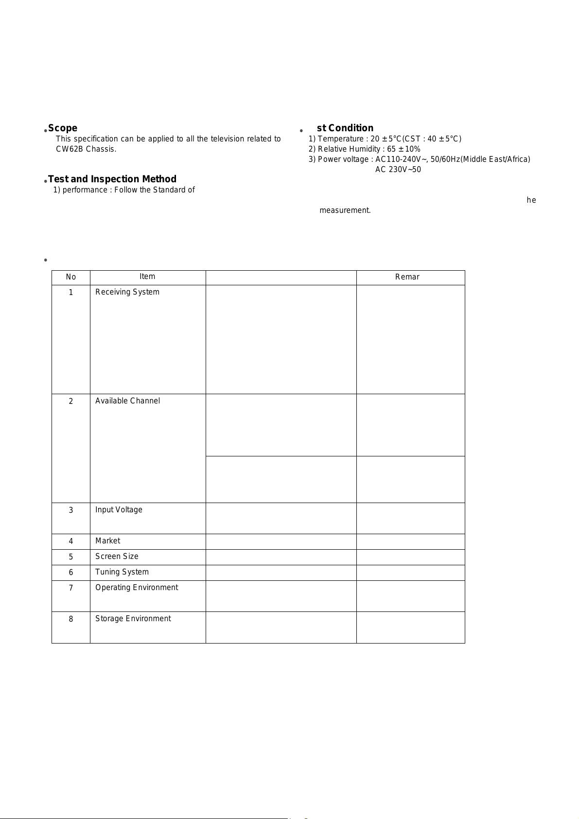
Scope
This specification can be applied to all the television related to
CW62B Chassis.
O2@@6Khe
W2@@@@@@6Xh
7@@@@@@@@1h
?J@@@@@@@@@@L?g
?7@@@@@@@@@@1?g
?@@@@@@@@@@@@?g
?@@@@@@@@@@@@?g
?3@@@@@@@@@@5?g
?N@@@@@@@@@@H?g
3@@@@@@@@5h
V4@@@@@@0Yh
I4@@0Mhe
Test and Inspection Method
1) performance : Follow the Standard of LG TV test
2) Standards of Etc. requirement
- Safety: IEC60065
- EMC: EN55020,EN55013
O2@@6Khe
W2@@@@@@6Xh
7@@@@@@@@1h
?J@@@@@@@@@@L?g
?7@@@@@@@@@@1?g
?@@@@@@@@@@@@?g
?@@@@@@@@@@@@?g
?3@@@@@@@@@@5?g
?N@@@@@@@@@@H?g
3@@@@@@@@5h
V4@@@@@@0Yh
I4@@0Mhe
Test Condition
1) Temperature : 20 ± 5°C(CST : 40 ± 5°C)
2) Relative Humidity : 65
± 10%
3) Power voltage : AC110-240V~, 50/60Hz(Middle East/Africa)
AC 230V~50/60Hz (EU/CIS)
4) Follow each drawing or spec for spec and performance of
parts,based upon P/N of B.O.M
5) Warm up TV set for more than 20min. before the
measurement.
No
1
2
3
4
5
6
7
8
Item
Receiving System
Available Channel
Input Voltage
Market
Screen Size
Tuning System
Operating Environment
Storage Environment
Remark
EU/ Non EU
OPTION
Non EU/ EU
NTSC-M
Non EU
EU
PAL 200 PR(W/O TXT)
Specification
PAL,SECAM BG
PAL/SECAM DK
PAL-I/I
NTSC M
NTSC 4.43(AV)
SECAM-L/L’
NTSC M/ PAL M/N
VHF : E2 ~ E12
UHF : E21 ~ E69
CATV : S1 ~ S20
HYPER : S21 ~ S41
VHF : 02 ~ 13
UHF : 14 ~ 69
CATV : 02 ~ 71
AC 110-240V, 50/60Hz
AC 230V, 50/60Hz
EU,CIS, China, Asia, Africa,Middle East
Flat 21”
FVS 100Program
1) Temp : 0 ~ 45 deg
2) Humidity : below 85%
1) Temp : -20 ~ 60 deg
2) Humidity : below 85%
O2@@6Khe
W2@@@@@@6Xh
7@@@@@@@@1h
?J@@@@@@@@@@L?g
?7@@@@@@@@@@1?g
?@@@@@@@@@@@@?g
?@@@@@@@@@@@@?g
?3@@@@@@@@@@5?g
?N@@@@@@@@@@H?g
3@@@@@@@@5h
V4@@@@@@0Yh
I4@@0Mhe
General Specification
1. Application Object
These instructions are applied to all of the color TV, CW62B.
2. Notes
(1) Because this is not a hot chassis, it is not necessary to use
an isolation transformer. However, the use of isolation
transformer will help protect test instrument.
(2) Adjustment must be done in the correct order.But the
adjustment can be changed by consideration of mass
production.
(3) The adjustment must be performed in the circumstance of
25±5°C of temperature and 65±10% of relative humidity if
there is no specific designation.
(4) The input AC voltage of the receiver must keep rating
voltage in adjusting.
(5) The receiver must be operated for about 20 minutes prior
to the adjustment.
(6) Signal: Received, the standard color signal.(65dB±1dB uV)
LG standard signal means the digital pattern
(PAL_EU 05CH,NTSC_US 13CH).
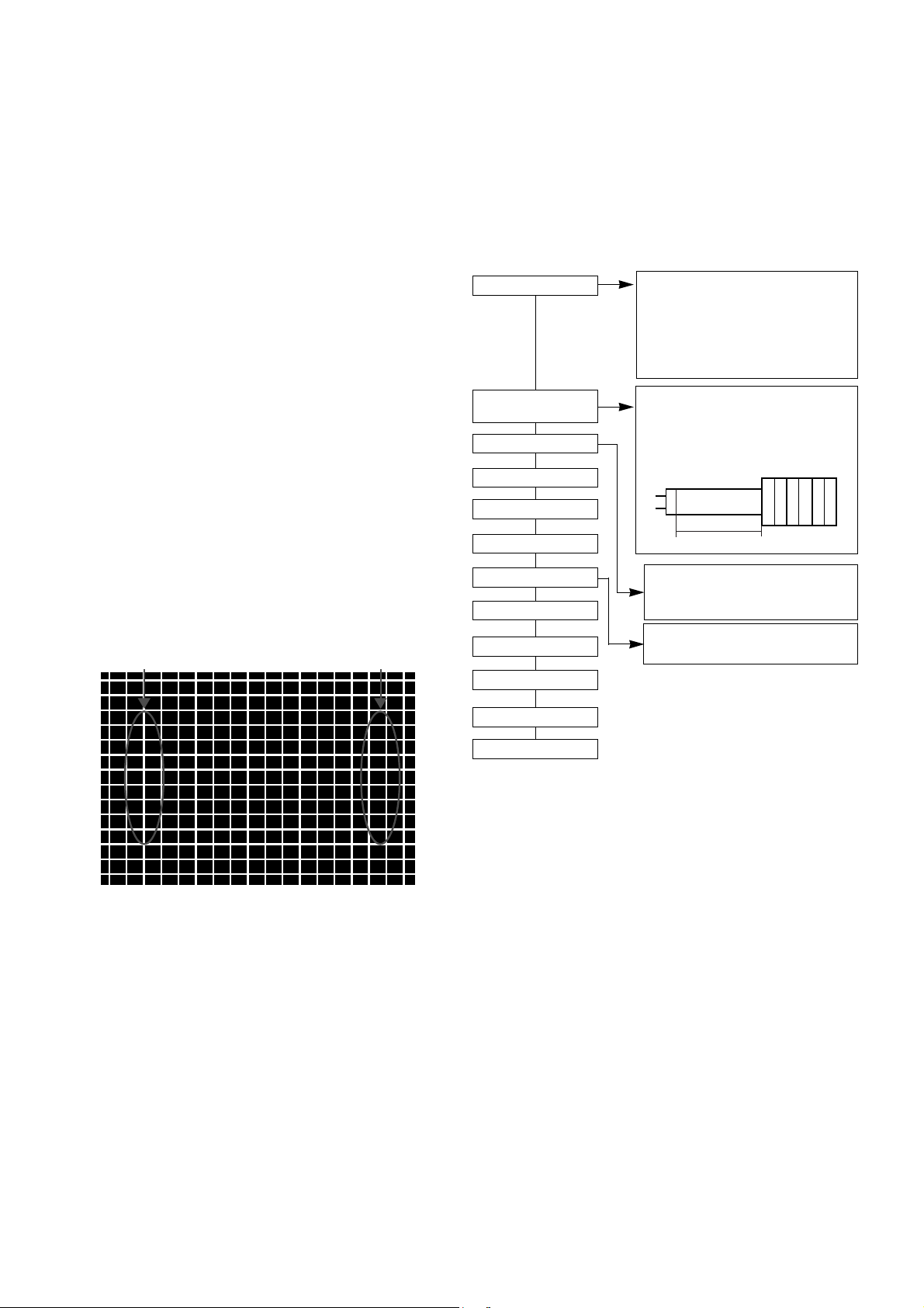
3. Focus adjustment
(1) Receive the Cross-Hatch Pattern(Fig 1).
(2) Set the picture condition on “DYNAMIC(CLEAR)” mode.
(3) Adjust the Focus volume of FBT,made the focus of the 1/4
part vertical line is best.
4. Purity & Convergence adjustment
Adjustment should be operated when using the CPT(without
ITC from CPT manufacturing place)
This adjustment must be done in the order of the following
flowchart.
4.1. Color purity adjustment
(1) It makes CPT or CABINET enough to demagnetization.
(2) Receive the signal of red raster.
(3) Unfasten DY and push DY to FUNNEL direction.
(4) Make R-Land be centered as cross Purity Magnet. That
time, 4 & 6 pole magnet should keep free gauss status.
(5) Make uniform RED Raster as moving DY,Check there is
purity problem or not on R/G/B,white Raster. Then fix screw
of DY.
(At this time, be careful about inclination and DY should be
fixed keeping horizontality.)
(6) Check the TV set in direction of EAST, WEST, SOUTH,
NORTH. Adjust with supporing MAGNET when adjustment
is not operated.
4.2. Convergence adjustment
These adjustments should be operaed at the best condition of
focus after finished purity adjustment.
(1) Receive the signal of cross hatch that BACK RASTER is
black.
(2) Adjust brightness so that there are 9 ~12 dots.
- 8 -
ADJUSTMENT INSTRUCTIONS
A
B
<Fig. 1> Cross-Hatch Pattern (NTSC : US 09CH, PAL : E-7CH)
Assembling DY to
CPT
CPT Assembling
As preparatory operations before
assembling CPT, wind cotton Tape for
protecting to CPT NECK and DY, CPT
connection parts. At this moment, end
of tape should be over-lapped and
wound in direct route to the NECK.
Let the screen Standard condition.
Operate Heat-Run at least 15
minutes.
Torque is to be 9-11 kg f.cm when
fixing DY.
Fix the Magnet to the position as
shown picture below. Be careful not to
make CPT neck shadow while
adjusting DY.
HEAT RUN
Degaussing
STC Pre-Adjustment
PURITY Adjustment
DY Fixing
SCREEN Voltage adj.
W/B Fixing
FOCUS not yet ADJ.
STC not yet ADJ.
DYC not yet ADJ.
Convergence Magnet
¢‚
15 ~ 20mm
6Pole
¢‚
4
2
(3) Widen two tabs of 4pole Magnet with equal angles and
accord red,blue vertical lines at the center of screen.
(4) With keeping angle of "c.clause",rotate tab and accord
red/blue,green vertical lines at the center of screen.
(5) Widen two tabs of 6pole Magnet with equal angles and
accord red,bllue vertical lines at the center of screen.
(6) With keeping angle of "e.clause",repeat the adjustment
from c to e keeping in mind the movement of
red,blue,green when the horizontal lines are twisted.
(7) Move the DY up,down,left,right and make the convergence
to be optimal condition and stick rubber wedge to CPT so
that the DY not to move.
5. Screen voltage adjustment
SCREEN manual adjust method(Used the remote controller)
(1) RF Mode,input the PAL or SECAM(NTSC)singal,every
channel is OK.
(2) First LINE SVC MODE(IN-START KEY) and push the ADJ
KEY change to the SCREEN adjustment MODE.
(3) Adjust the SCREEN VOL of the FBT,then TV picture will
be have a horizontal line,manual adjust the FBT SCREEN
VOL,when the horizontal line just disappear is OK
(Press the TV/AV button to exit SVC mode)
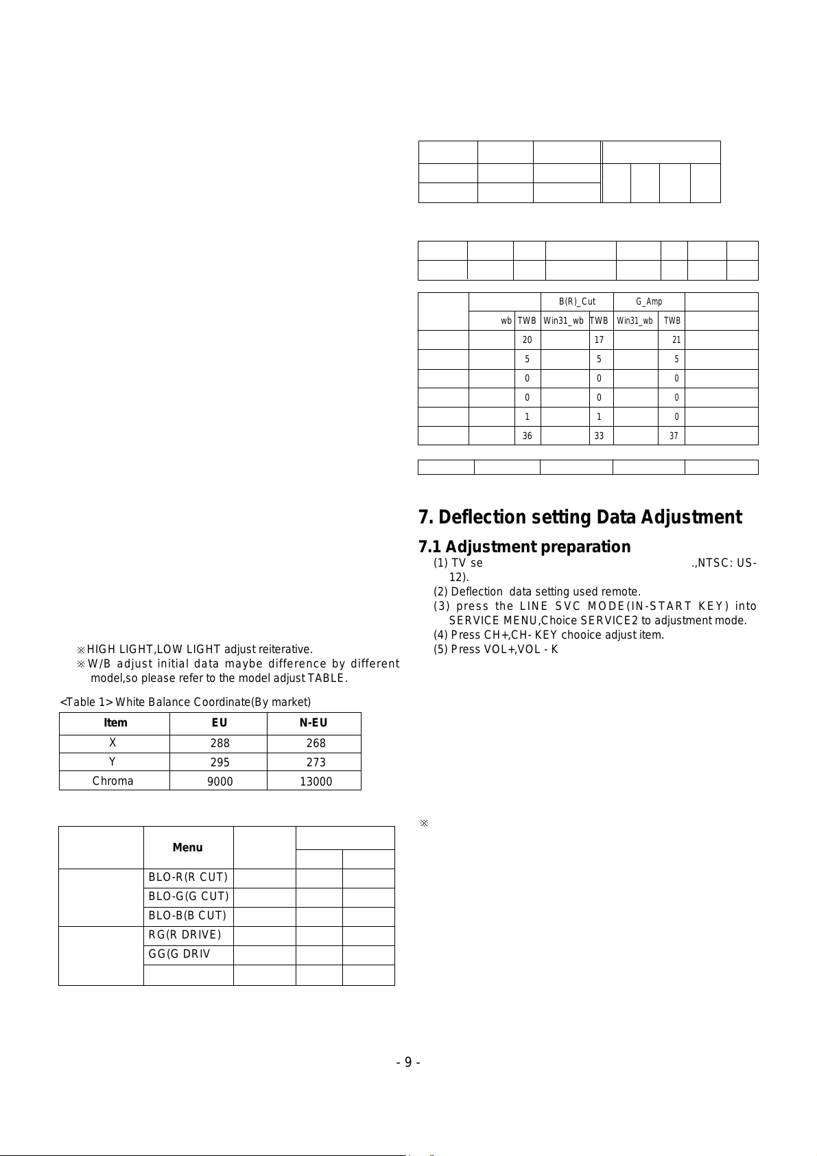
6. White balance adjustment
(1) Receive 100% white pattern.
(2) From the initial data,adjust BLO-R(R CUT),BLO-G(G CUT)
keep X,Y coordinate settle for the below list,adjust the
LOW LIGHT(4.5FL).
(3) From the initial data:BG(B-DRIVE) is 32,adjust RG(R-
DRIVE),GG(G-DRIVE) keep X,Y coordinate settle for the
below list,adjust the HIGH LIGHT(35FL).
?
?
?
?
?
?
?
?
?
?
?
?W&?he?
?'6Xe?*@?eW2(?f?
?V')X??V'??W&(Y?f?
V')XfW&(Yg?
?V')X??W&(Y?g?
V')KO&(Yh?
W-X??V'@@(Y??W-Xf?
&@)?e?@@?e?&@)f?
?W&@@)X?h?
W&(MI')Xh?
?W&(Y??V')X?g?
W&(YfV')Xg?
?W&(Y??W&??V')X?f?
?&0Ye?*@?eV4)?f?
?V'?he?
?
?
?
?
?
?
?
HIGH LIGHT,LOW LIGHT adjust reiterative.
?
?
?
?
?
?
?
?
?
?
?
?W&?he?
?'6Xe?*@?eW2(?f?
?V')X??V'??W&(Y?f?
V')XfW&(Yg?
?V')X??W&(Y?g?
V')KO&(Yh?
W-X??V'@@(Y??W-Xf?
&@)?e?@@?e?&@)f?
?W&@@)X?h?
W&(MI')Xh?
?W&(Y??V')X?g?
W&(YfV')Xg?
?W&(Y??W&??V')X?f?
?&0Ye?*@?eV4)?f?
?V'?he?
?
?
?
?
?
?
?
W/B adjust initial data maybe difference by different
model,so please refer to the model adjust TABLE.
7. Deflection setting Data Adjustment
7.1 Adjustment preparation
(1) TV set to receive an Digital pattern(PAL:E5ch.,NTSC: US-
12).
(2) Deflection data setting used remote.
(3) press the LINE SVC MODE(IN-START KEY) into
SERVICE MENU,Choice SERVICE2 to adjustment mode.
(4) Press CH+,CH- KEY chooice adjust item.
(5) Press VOL+,VOL - KEY increase or decrease DATA.
7.2 Adjustment
(1) First,adjust deflection at 50Hz,of PAL signal.
then,adjust deflection at 60Hz, of NTSC signal.
(2) Korea Model only used the N60Hz,adjustment .
Adjust vertical inclination of screen.
(3) Central or South America Model first N60Hz adjustment
and then N50(PAL-N) adjustment.
(4) when finish the adjustment and press"ENTER" KEY,save
data andexit adjustment Mode.
?
?
?
?
?
?
?
?
?
?
?
?W&?he?
?'6Xe?*@?eW2(?f?
?V')X??V'??W&(Y?f?
V')XfW&(Yg?
?V')X??W&(Y?g?
V')KO&(Yh?
W-X??V'@@(Y??W-Xf?
&@)?e?@@?e?&@)f?
?W&@@)X?h?
W&(MI')Xh?
?W&(Y??V')X?g?
W&(YfV')Xg?
?W&(Y??W&??V')X?f?
?&0Ye?*@?eV4)?f?
?V'?he?
?
?
?
?
?
?
?
Deflection adjustment small item
(1) V SLOPE
The cutting part(below) of picture transfer to Blanking.
Adjust the geometric vertical center of the CPT is in accord
lower blanking.
(2) VS (Vertical Shift)
Adjust so that the horizontal center line of a digital circle
pattern is in accord with geometric horizontal center of the
CPT.
2. White balance IIC Parameter(Address)
Program
Sub Add
Start Bit
Stop Bit
Offset
Polarity
EP_Rom_S
B(R)_Amp
Win31_wb TWB
20
5
0
0
1
36
B(R)_Cut
Win31_wb TWB
17
5
0
0
1
33
G_Amp
Win31_wb TWB
21
5
0
0
0
37
- 9 -
Item EU N-EU
X
Y
Chroma
288
295
9000
268
273
13000
<Table 1> White Balance Coordinate(By market)
Menu
BLO-R(R CUT)
BLO-G(G CUT)
BLO-B(B CUT)
RG(R DRIVE)
GG(G DRIVE)
BG (B DRIVE)
LOW LIGHT
HIGH LIGHT
0 ~ 63
0 ~ 63
0 ~ 63
0 ~ 63
0 ~ 63
0 ~ 63
32
32
32
32
32
32
Range
DATA
<Table 2> White Balance Initial Data
<Table 3> White Balance Initial Data
1. IC PARAMETER
VCD IC
EP_ROM
0 0 0 0
Name
Maker Algorithm
Program
Vcd Slave
Win31_wb
TWB
8A
Eeprom_Slave
Win31_wb
TWB
A0
Speed1Delay
30
G_Cut
Win31_wb TWB
18
5
0
0
0
34
Speed/ Plus 2 2 2 2
PAL
Menu
NTSC
32
32
32
32
32
32
 Loading...