

LG 21FJ4AB/RB, 21FJ4AB/RB-TH Service Manual
Driver Install Guide Specification
Driver Install Guide Specification
담 당 관리자
Model Description
1.
MODEL
SUFFIX
2.
21FJ4AB-TH
KDRLCEY
Printing Specification
1. Trim Size (Format) : 215mm x 280 mm
2. Printing Colors
• Cover : 2 Colors (Black and Pantone 207C)
• Inside : 1 Color (Black)
3. Stock (Paper)
• Cover : Uncoated paper 100 g/㎡
• Inside : Uncoated paper 100 g/㎡
4. Printing Method :
5. Bindery : Saddle stitch
6. Language : English
7. Number of pages : 28 pages
BRAND
Product Name
LG
SVC Manual
KIM S H
06.12.22
Part No.
KANG K S
06.12.22
MFL31479115
NOTE
3.
10
9
8
7
6
5
4
• This part contain Eco-hazardous substances (Pb, Cd, Hg, Cr6+, PBB, PBDE, etc.)
within LG standard level, Details should be followed Eco-S C M management
standard[LG(56)-A-2524].
• Especially, Part should be followed and controlled the following specification.
(1) Eco-hazardous substances test report should be submitted when Part certification
test and First Mass Production.
(2) Especially, Don’t use or contain lead(Pb) and cadmium(Cd) in ink.
Changes
3
2
1
REV.
MM/DD/YY
NO.
SIGNATURE
CHANGE NO.
CHANGE CONTENTS
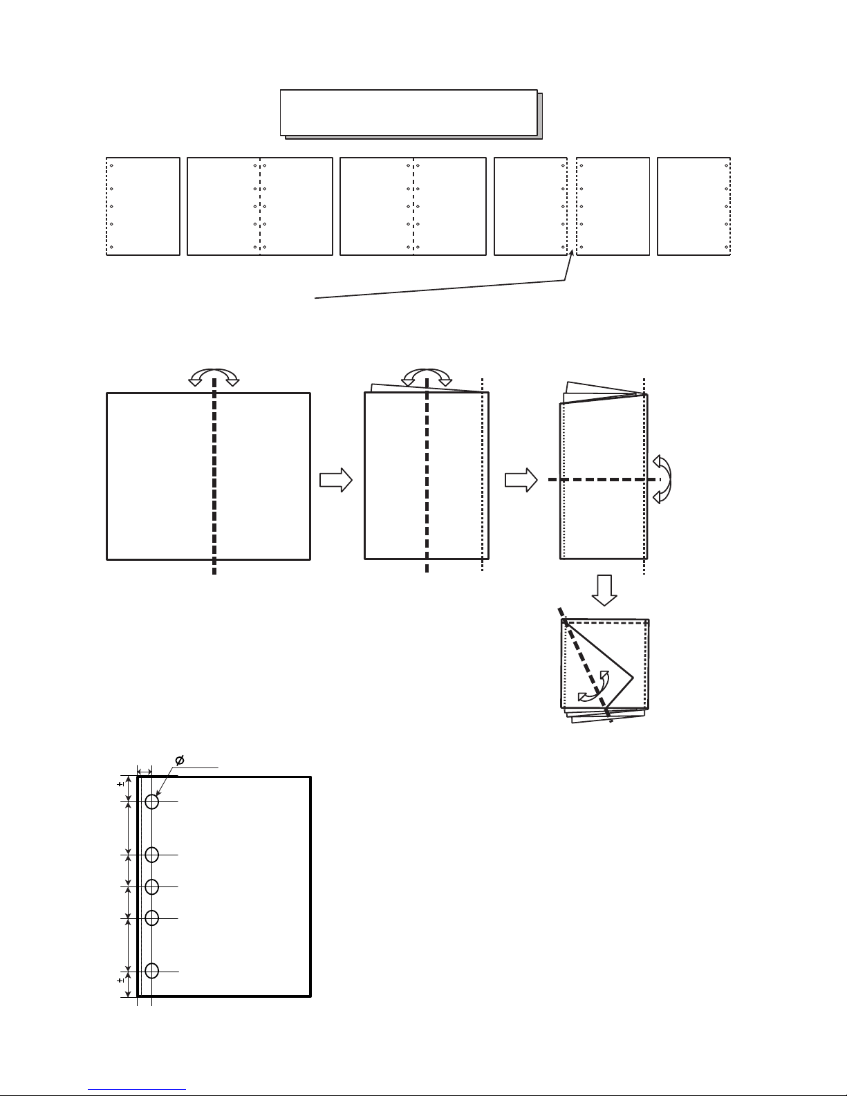
Fold 1
Fold 2
Fold 3
Fold 4
7 x 5
COLOR TV
SERVICE MANUAL
30.5 2
67
33.2 2
4067 40
Punching spec
Schematic diagram
9
unit : mm
Pagination sheet
P/NO . MFL31479115
Total pages : 28 pages
Front
Cover
(EN)
EN
2
EN
3
EN
4 ...
EN
26
27
Back
Cover
(EN)
MAIN
Front
Cover
Inside
Back
Cover
Inside
3854VA0196B-S1
3854VA0196B-S1
2005.8.16
P/N : 3854VA0196B-S1

COLOR TV
SERVICE MANUAL
CAUTION
BEFORE SERVICING THE CHASSIS,
READ THE SAFETY PRECAUTIONS IN THIS MANUAL.
CHASSIS : MC-059B
MODEL: 21FJ4AB/RB
MODEL:
21FJ4AB/RB-TH
website:http://biz.LGservice.com

- 2 -
CONTENTS
CONTENTS ............................................................................................... 2
SAFETY PRECAUTIONS...........................................................................3
DESCRIPTION OF CONTROLS ................................................................4
SPECIFICATIONS ......................................................................................6
ADJUSTMENT ...........................................................................................8
PRINTED CIRCUIT BOARD ....................................................................13
TROUBLE SHOOTING ............................................................................14
BLOCK DIAGRAM ...................................................................................18
EXPLODED VIEW ....................................................................................20
EXPLODED VIEW PARTS LIST ..............................................................21
REPLACEMENT PARTS LIST................................................................ 22
- 3 -
SAFETY PRECAUTIONS
Many electrical and mechanical parts in this chassis have special safety-related characteristics. These parts are identified by in the
Schematic Diagram and Replacement Parts List.
It is essential that these special safety parts should be replaced with the same components as recommended in this manual to prevent
X-RADIATION, Shock, Fire, or other Hazards.
Do not modify the original design without permission of manufacturer.
General Guidance
An isolation Transformer should always be used during the
servicing of a receiver whose chassis is not isolated from the AC
power line. Use a transformer of adequate power rating as this
protects the technician from accidents resulting in personal injury
from electrical shocks.
It will also protect the receiver and it's components from being
damaged by accidental shorts of the circuitry that may be
inadvertently introduced during the service operation.
If any fuse (or Fusible Resistor) in this TV receiver is blown,
replace it with the specified.
When replacing a high wattage resistor (Oxide Metal Film Resistor,
over 1W), keep the resistor 10mm away from PCB.
Keep wires away from high voltage or high temperature parts.
Due to high vacuum and large surface area of picture tube,
extreme care should be used in handling the Picture Tube. Do
not lift the Picture tube by it's Neck.
X-RAY Radiation
Warning:
To determine the presence of high voltage, use an accurate high
impedance HV meter.
Adjust brightness, color, contrast controls to minimum.
Measure the high voltage.
The meter reading should indicate
23.5 ± 1.5KV: 14-19 inch, 26 ± 1.5KV: 19-21 inch,
29.0 ± 1.5KV: 25-29 inch, 30.0 ± 1.5KV: 32 inch
If the meter indication is out of tolerance, immediate service and
correction is required to prevent the possibility of premature
component failure.
Before returning the receiver to the customer,
always perform an AC leakage current check on the exposed
metallic parts of the cabinet, such as antennas, terminals, etc., to
be sure the set is safe to operate without damage of electrical
shock.
Leakage Current Cold Check(Antenna Cold Check)
With the instrument AC plug removed from AC source, connect an
electrical jumper across the two AC plug prongs. Place the AC
switch in the on position, connect one lead of ohm-meter to the AC
plug prongs tied together and touch other ohm-meter lead in turn to
each exposed metallic parts such as antenna terminals, phone
jacks, etc.
If the exposed metallic part has a return path to the chassis, the
measured resistance should be between 1MΩ and 5.2MΩ.
When the exposed metal has no return path to the chassis the
reading must be infinite.
An other abnormality exists that must be corrected before the
receiver is returned to the customer.
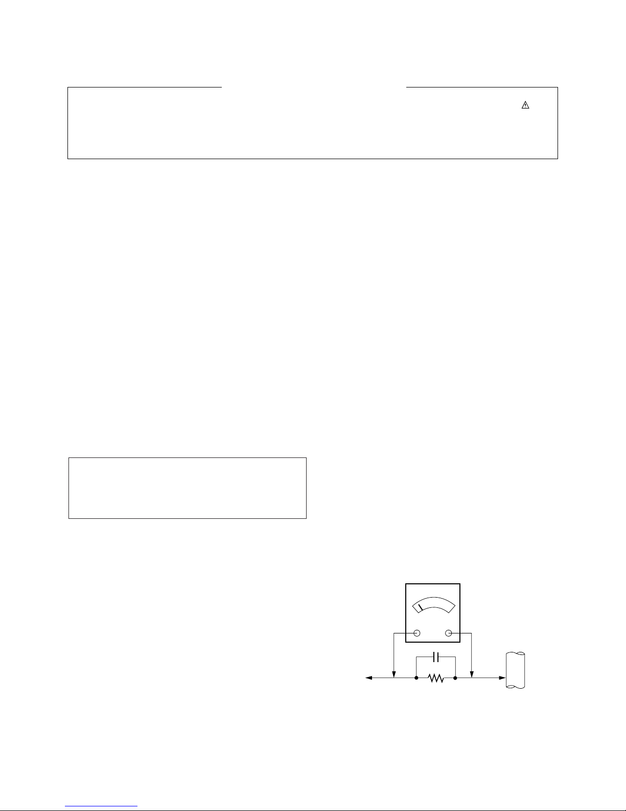
Leakage Current Hot Check (See below Figure)
Plug the AC cord directly into the AC outlet.
Do not use a line Isolation Transformer during this check.
Connect 1.5K/10watt resistor in parallel with a 0.15uF capacitor
between a known good earth ground (Water Pipe, Conduit, etc.)
and the exposed metallic parts.
Measure the AC voltage across the resistor using AC voltmeter
with 1000 ohms/volt or more sensitivity.
Reverse plug the AC cord into the AC outlet and repeat AC voltage
measurements for each exposed metallic part. Any voltage
measured must not exceed 0.75 volt RMS which is corresponds to
0.5mA.
In case any measurement is out of the limits specified, there is
possibility of shock hazard and the set must be checked and
repaired before it is returned to the customer.
Leakage Current Hot Check circuit
The source of X-RAY RADIATION in this TV receiver is the High
Voltage Section and the Picture Tube.
For continued X-RAY RADIATION protection, the replacement
tube must be the same type tube as specified in the
Replacement Parts List.
1.5 Kohm/10W
To Instrument’s
exposed
METALLIC PARTS
Good Earth Ground
such as WATER PIPE,
CONDUIT etc.
AC Volt-meter
IMPORTANT SAFETY NOTICE
0.15uF
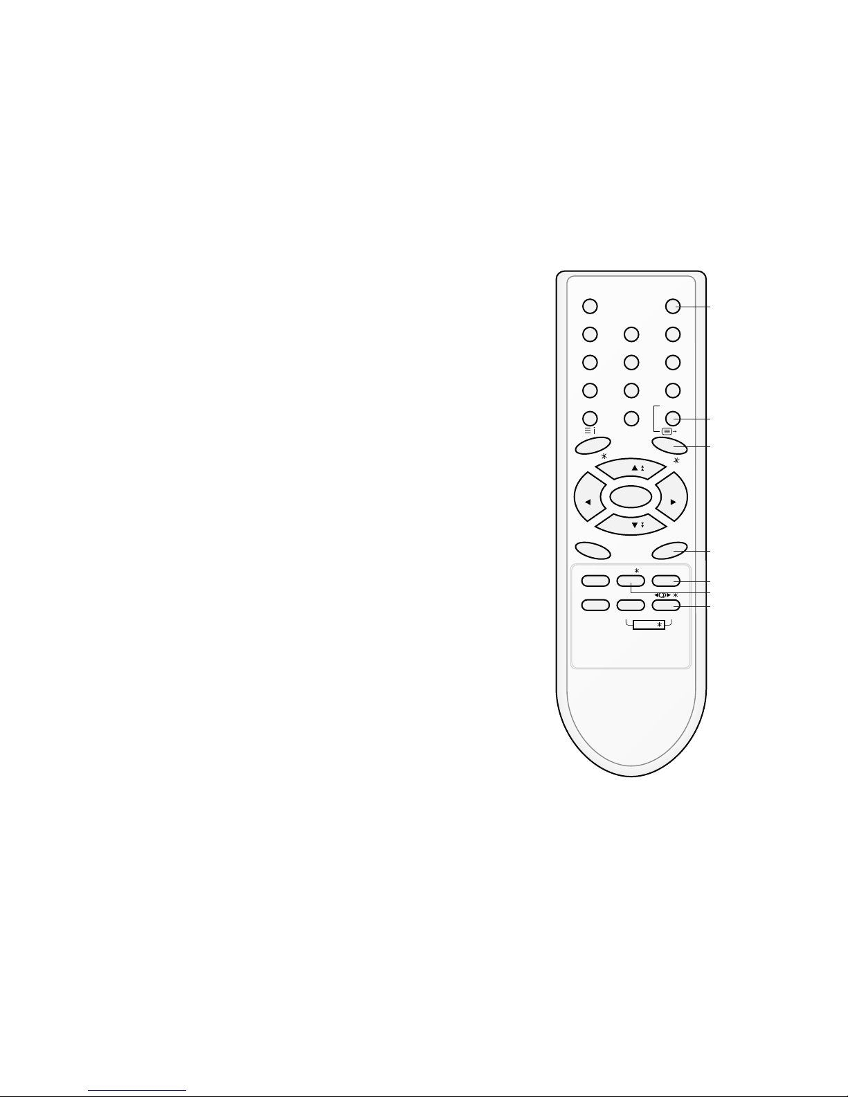
All the functions can be controlled with the remote control handset.
Some functions can also be adjusted with the buttons on the front
panel of the set.
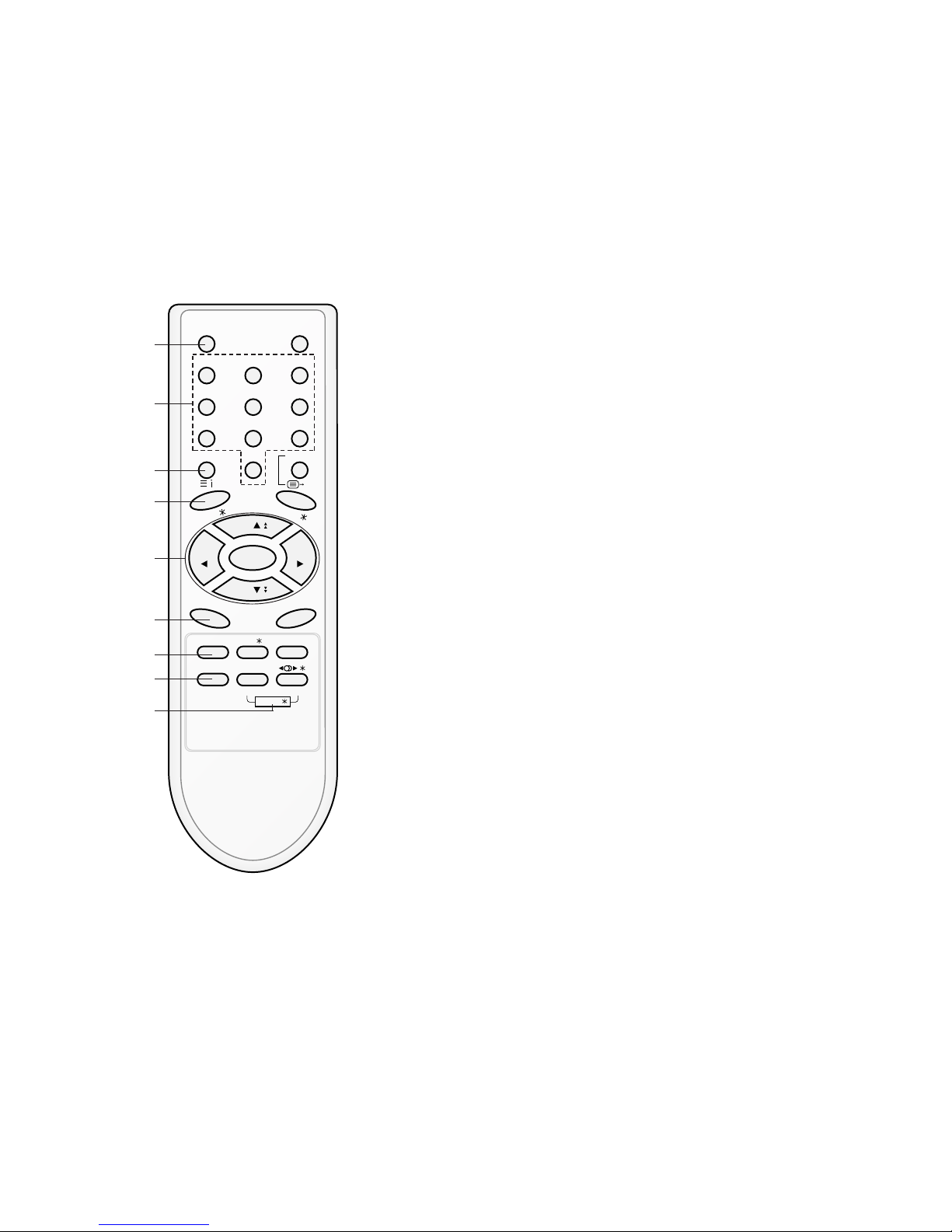
Remote control handset
Before you use the remote control handset, please install the batteries. See the next page.
1. POWER
switches the set on from standby or off to standby.
2. NUMBER BUTTONS
switches the set on from standby or directly select a number.
3. MENU (or INDEX)
selects a menu.
selects an index page in the teletext mode (only TELETEXT
models). (option)
4. EYE/*(option)
switches the eye function on or off.
5.
DD/ EE
(Programme Up/Down)
selects a programme or a menu item.
switches the set on from standby.
scans programmes automatically.
FF / GG
(Volume Up/Down)
adjusts the volume.
adjusts menu settings.
OK
accepts your selection or displays the current mode.
6. Q.VIEW
returns to the previously viewed programme.
7. PSM (Picture Status Memory)
recalls your preferred picture setting.
8. FAVOURITE
selects a favorite programme.
9. TURBO PICTURE / SOUND BUTTON (option)
selects Turbo picture and sound.
POWER MUTE
123
456
789
MENU/INDEX
TV/AV
0
EYE/
Q.VIEW
LIST
I / II /
( )
PR
( )
PR
OK
VOLVOL
PSM SSM/ SLEEP
PICTURE SOUND
/
TURBO/
FAVOURITE
TV
1
2
3
4
5
6
7
9
8
- 4 -
DESCRIPTION OF CONTROLS
- 5 -
10. MUTE
switches the sound on or off.
11. TV/AV
selects TV or AV mode.
switches the set on from standby.
12. I/II/*(option)
selects the language during dual language broadcast. (option)
selects the sound output.
13. LIST
displays the programme table.
14. SLEEP
sets the sleep timer.
15. SSM/*(Sound Status Memory) (option)
recalls your preferred sound setting.
16. SURROUND (ºº/*) (option)
selects surround sound.
*
: No function
COLOURED BUTTONS : These buttons are used for teletext (only
TELETEXT models) or programme edit.
POWER MUTE
123
456
789
MENU/INDEX
TV/AV
0
EYE/
Q.VIEW
LIST
I / II /
( )
PR
( )
PR
OK
VOLVOL
PSM SSM/ SLEEP
PICTURE SOUND
/
TURBO/
FAVOURITE
TV
10
11
12
13
14
16
15
V Scope
This specification can be applied to all the television related to
MC-059B Chassis.
V Requirement for Test
Each part is tested as below without special appointment.
1) Temperature : 25 ± 5°C (77 ± 9°F), CST : 40 ± 5
(CST must be tested 40
± 5°C . Humidity : 50%)
2) Relative Humidity : 65
± 10%
3) Power Voltage : Standard input Voltage (110-240V~,
50/60Hz)
* Standard Voltage of each products is marked by models.
4) Specification and performance of each parts are followed
each drawing and specification by part number in
accordance with BOM.
5) The receiver must be operated for about 20 minutes prior to
the adjustment.
V Test Method
1) Performance : LGE TV test method followed.
2) Demanded other specification
- CCC
- Safety : IEC60065
- 6 -
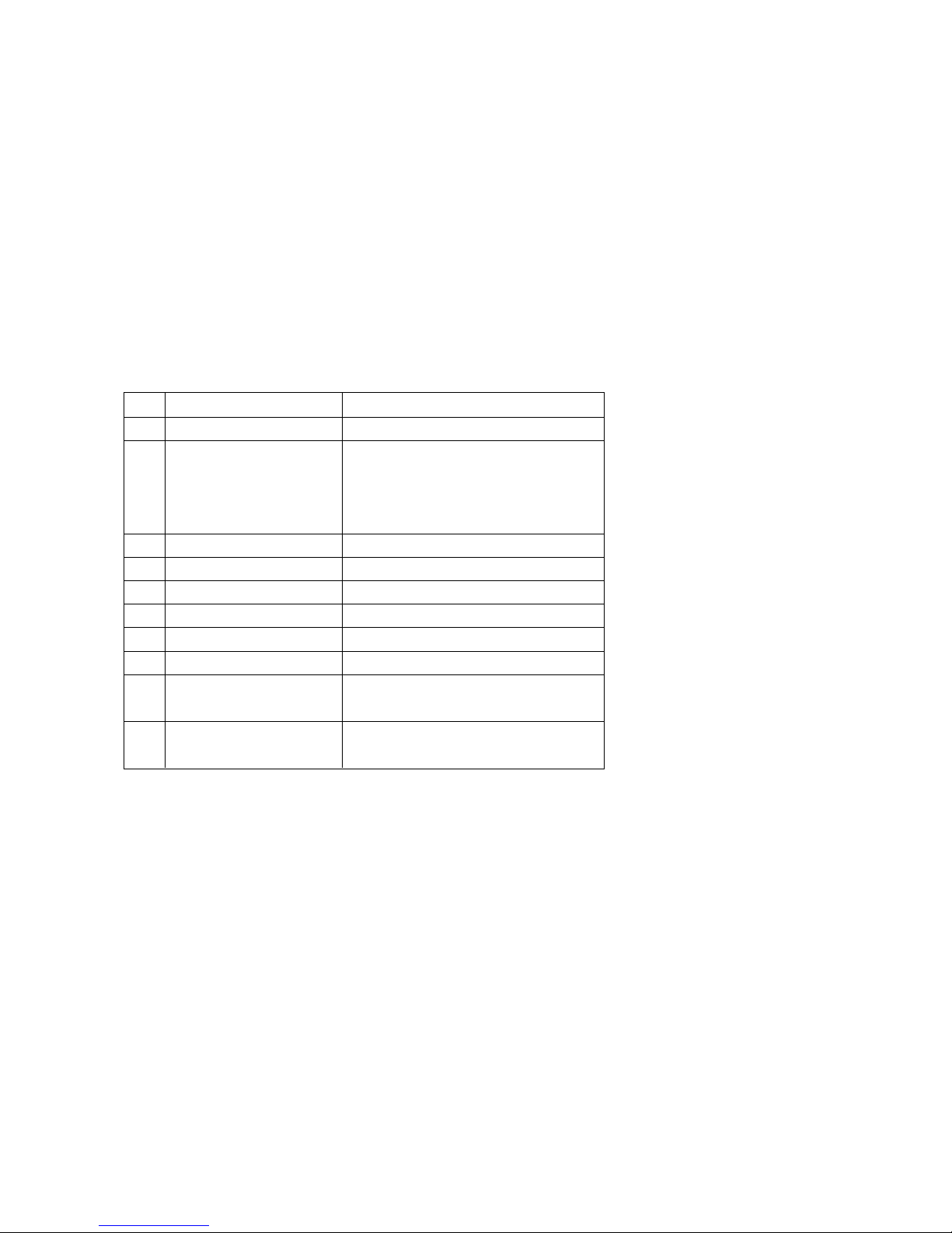
A General specification
SPECIFICATIONS
Note : Specification and others are subject to change without notice for improvement.
Item
Receiving System
Available Channel
Input Voltage
Market
Screen Size
Aspect Ratio
Display Method
Tuning System
Operating Environment
Storage Environment
Specification
PAL BG, DK, I / NTSC M (AV 3.58/ 4.43)
VHF : E2 ~ E12
UHF : E21 ~ E69
CATV : S1 ~ S20
HYPER : S21 ~ S41
100 - 240V~, 50/60Hz
China, Indonesia, Thai, Vietnam, CIS
14 ~ 21inch (FLAT / Conventional)
4:3
CRT
FVS
Temp : 0 ~ 40 deg
Humidity : ~ 85 %
Temp : -20 ~ 60 deg
Humidity : ~ 90 %
No.
1
2
3
4
5
6
7
8
9
10
- 7 -
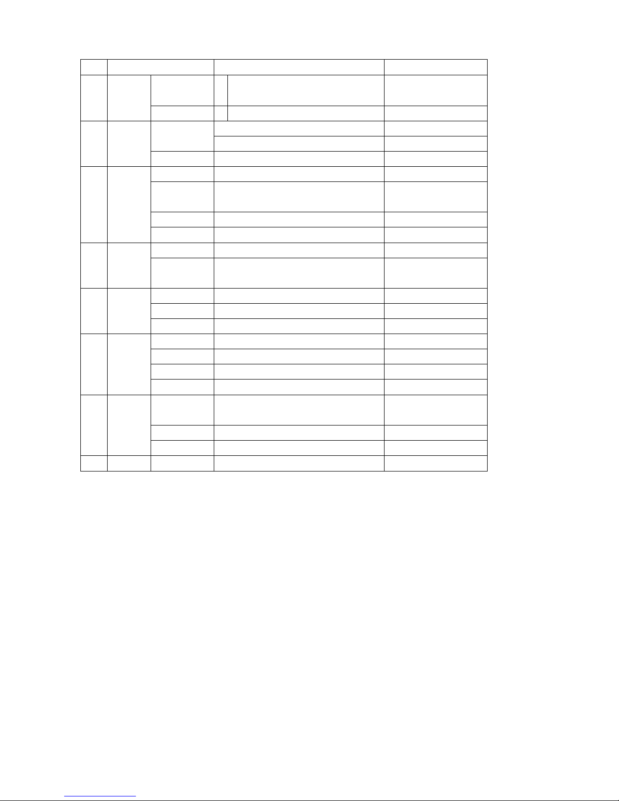
A Features and Function
Item
Feature AV Input
AV Output
Earphone
Key Local Key
Remocon
Channel Auto prog.
Manual
Prog. edit
Favorite
Picture PSM
User Control
Sound SSM
Treble/ Bass
Equalizer
Timer Clock
Off time
On time
Auto off
Special Language
Input
Child lock
Etc. Sleep
Specification
2 AV 1, 2
1 Monitor out
1 Front
Power, Vol(
F, G), PR(E, D), MENU, OK
Turbo-Picture, Sound
LG Code (NEC)
System/ Storage/ Normal/ Turbo
Storage/ System/ Channel/ Fine/
Search/ Name
Copy/ Move/ Delete/ Skip
8 Channel
Dynamic/ Standard/ Mild/ Game/ User
Contrast/ Brightness/ Color/ Sharpness
Tint (NTSC-M Only)
Flat/ Music/ Movie/ Speech/ User
0 ~ 100
100/ 400/ 1K/ 4K/ 10K
-- : --
-- : -- Off(On)
-- : -- Pr 1 VOL 30 Off(On)
On/ Off
English/ Russia
English/ Indonesia/ Thai/ Vietnam
TV/ AV1/ AV2
On/ Off
Remark
Rear1, Front1(CVBS,L,R)
Rear
7EA/ Front
Option
CIS
East-Asia
No.
1
2
3
4
5
6
7
8
 Loading...