

Page 1

OWNER’S MANUAL
ENGLISH
LED MONITOR
Please read this manual carefully before operating your set and
retain it for future reference.
LED MONITOR MODEL
19EB13T
www.lg.com
Page 2
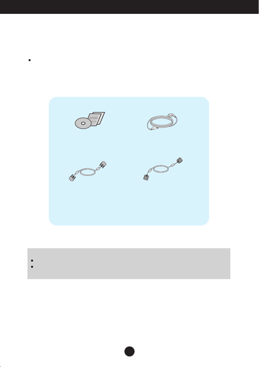
Accessories
!!! Thank for selecting LGE products !!!
Please make sure the following items are included with your
monitor. If any items are missing, contact your dealer.
User's Guide/Cards
DVI-D Signal Cable
(This feature is not available in all
countries.)
NOTE
This accessories may look different from those shown here.
User must use shielded signal interface cables (D-sub 15 pin cable, DVI-D cable) with ferrite
cores to maintain standard compliance for the product.
Power Cord
15-pin D-Sub Signal Cable
(To set it up, this signal cable may be
attached to this product before
shipping out.)
1
Page 3
Connecting the Display
.
Before setting up the monitor, ensure that the power to the monitor, the computer
system, and other attached devices is turned off.
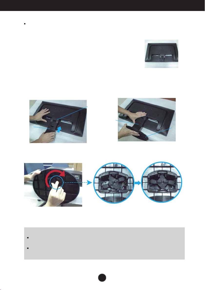
Connecting the stand
1. Place the monitor with its front facing downward on a soft cloth.
2. Assemble the Stand Body into the
product in the correct direction as shown in
the picture. Make sure you push it until you
hear it “click”.
Hinge Body
Stand Body
3. Assemble the Stand Base(Front,
Rear) into the Stand Body in the
correct direction.
Stand Body
4. Tie down the base lock to perpendicularity direction.
5. Once assembled take the monitor up carefully and face the front side.
Stand Base
Important
This illustration depicts the general model of connection. Your monitor may differ from
the items shown in the picture.
Do not carry the product upside down holding only the stand base. The product may
fall and get damaged or injure your foot.
2
Page 4
Connecting the Display
..
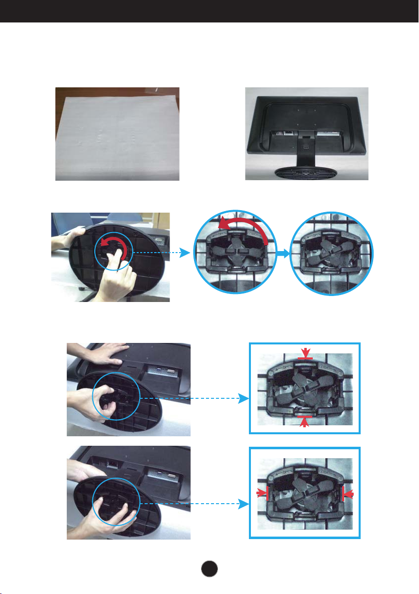
Disassembling the stand
1. Put a cushion or soft cloth on aflat
surface.
2. Place the monitor face Down on the
cushion or soft cloth.
3. Change your lock on the product as it follows and turn it in the arrow direction.
If you can't release the stand base even the locking knob is at a release
position, Please push the indicated knob down and retry it.
3
Page 5
Connecting the Display
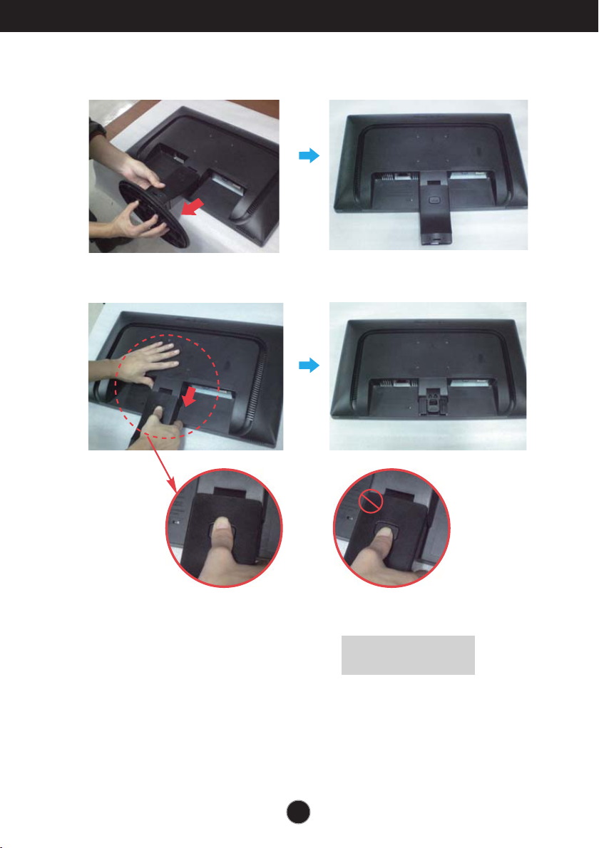
4.
Pull out the Stand to remove.
5.
Pushing the PUSH button, Take the stand body from hinge body.
Good Position Bad Position
Warning:
You can hurt your finger.
4
Page 6
Connecting the Display
Before setting up the monitor, ensure that the power to the monitor,
the computer system, and other attached devices is turned off.
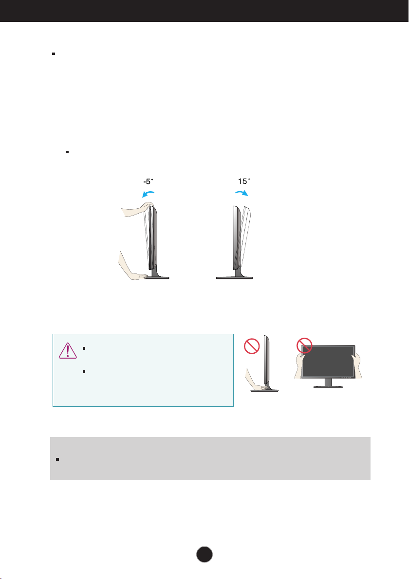
Positioning your display
-After installation, adjust the angle as shown below.
1. Adjust the position of the panel in various ways for maximum comfort.
Tilt Range : -5˚ to 15˚
Do not touch or press the screen when
adjusting the angle of the monitor.
When adjusting the angle of the screen, do
not put your finger(s) in between the head of
the monitor and the stand body. You can
hurt your finger(s).
ERGONOMIC
It is recommended that in order to maintain an ergonomic and comfortable viewing position,
the forward tilt angle of the monitor should not exceed 5 degrees.
5
Page 7
Connecting the Display
PC
PC
A
B
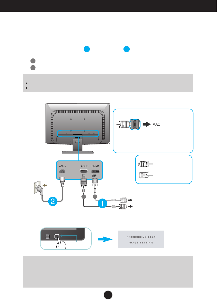
Connecting with the PC
1. Before setting up the monitor, ensure that the power to the monitor, the computer
system, and other attached devices is turned off.
2.
Connect signal input cable and power cord in order, then tighten the screw
of the signal cable.
A
Connect DVI-D(Digital signal) Cable
B
Connect D-sub(Analog signal) Cable
NOTE
This is a simplified representation of the rear view.
This rear view represents a general model; your display may differ from the view as shown.
Varies according to model.
Wall-outlet type
1
2
When using a D-Sub signal input cable connector
for Macintosh
Mac adapter : For Apple Macintosh use, a
separate plug adapter is needed to change the
15 pin high density (3 row) D-sub VGA
connector on the supplied cable to a 15 pin 2
row connector.
Connect the signal
input cable and tighten
it up by turning in the
direction of the arrow
as shown in the figure.
DVI-D (This feature is not available in all countries.)
3. Press the power button on the front panel to turn the power on. When monitor power is
turned on, the 'Self Image Setting Function' is executed automatically.
(Only Analog Mode)
Power Button
NOTE
‘ Self Image Setting Function’? This function provides the user with optimal display
settings.When the user connects the monitor for the first time, this function automatically adjusts
the display to optimal settings for individual input signals.
‘AUTO’ Function? When you encounter problems such as blurry screen, blurred letters, screen
flicker or tilted screen while using the device or after changing screen resolution, press the
AUTO function button to improve resolution.
6
Page 8
Control Panel Functions
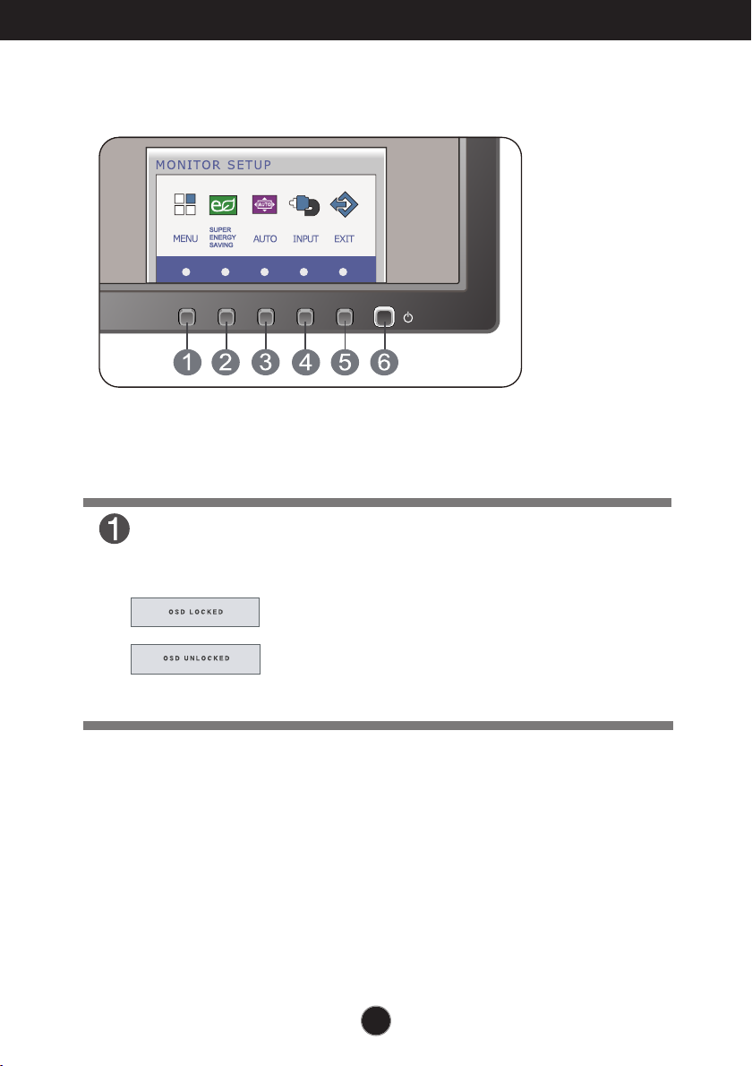
Front Panel Controls
MENU Button
OSD LOCKED/UNLOCKED
This function allows you to lock the current control
settings, so that they cannot be inadvertently changed.
Press and hold the MENU button for several seconds.
The message "OSD LOCKED" should appear.
You can unlock the OSD controls at any time by pushing
the MENU button for several seconds. The message
"OSD UNLOCKED" should appear.
7
Page 9

Control Panel Functions
SUPER ENERGY
SAVING Button
AUTO Button
INPUT Button
(SOURCE Hot key)
Use this button to enter
menu.For more information, refer to page 14.
AUTO IMAGE ADJUSTMENT
When adjusting your display settings, always press the
AUTO button before entering the On Screen
Display(OSD). (Only Analog Mode)
This will automatically adjust your display image to the
ideal settings for the current screen resolution size
(display mode).
The best display mode is
19EB13T:1366 x 768
When two input signals are connected, you can select the
input signal (D-SUB/DVI) you want. When only one signal
is connected, it is automatically detected. The default
setting is D-Sub.
SUPER ENERGY SAVING
EXIT Button
Power Button &
Power Indicator
Exit the OSD(On Screen Display).
Use this button to turn the display on or off.
The power indicator stays white if the display is running
properly (On Mode). If the display is in Sleep Mode
(Energy Saving), the power indicator is blinking white.
8
Page 10
On Screen Display (OSD) Control Adjustment
Screen Adjustment
Making adjustments to the image size, position and operating
parameters of the display is quick and easy with the On Screen
Display Control system.
A short example is given below to familiarize you with the use of the
controls. The following section is an outline of the available
adjustments and selections you can make using the OSD.
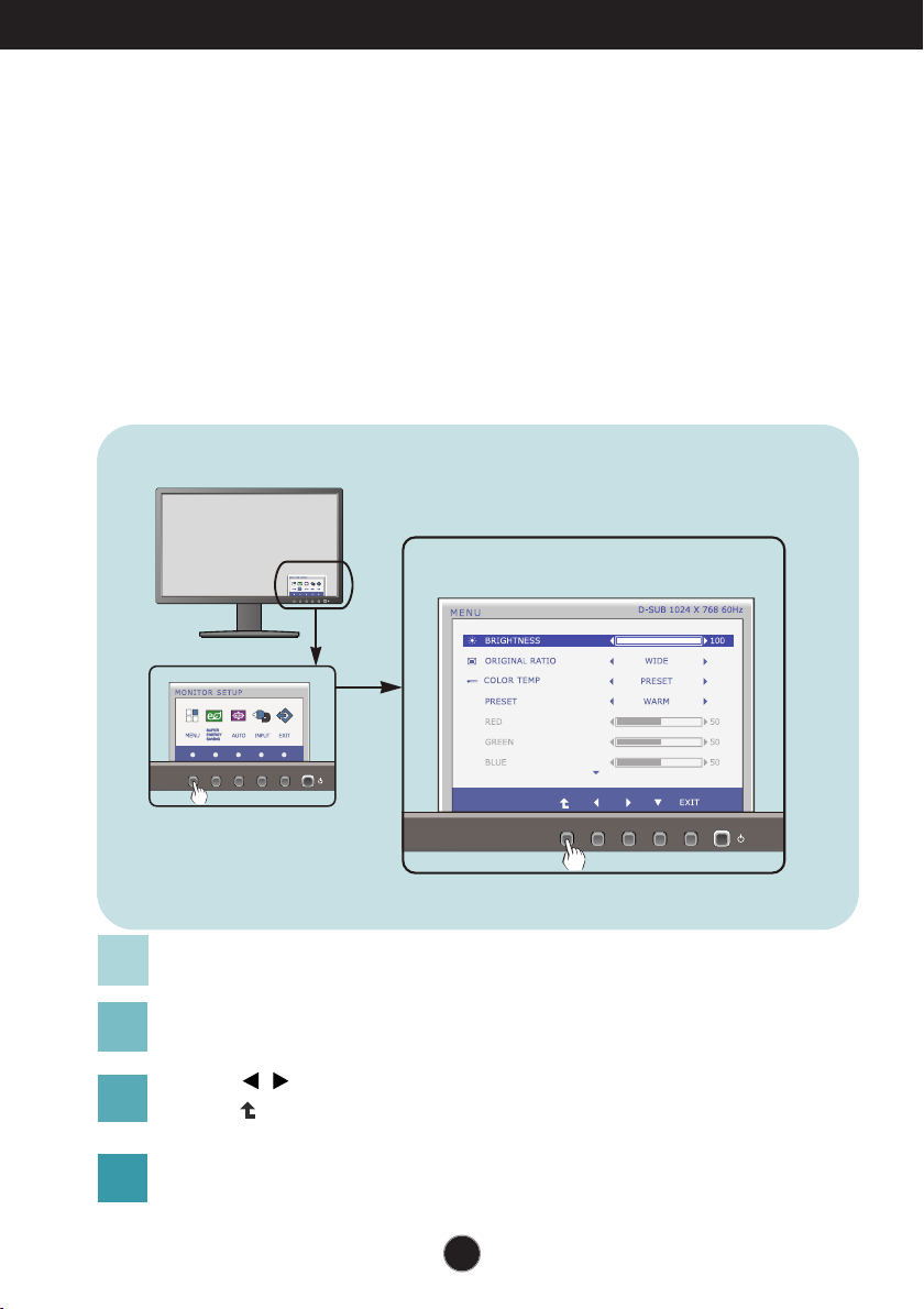
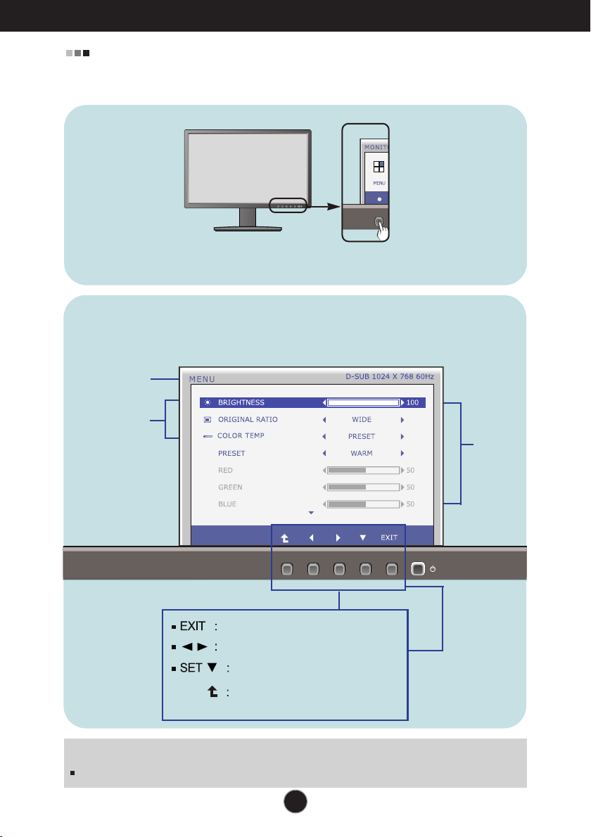
To make adjustments in the On Screen Display, follow these steps:
Press the discretionary Button, then the main menu of the OSD appears.
1
To access a control, use the corresponding Buttons.
2
Use the / Buttons to adjust the image to the desired level.
3
Use the Button to select other sub-menu items.
Press the EXIT Button to exit from the OSD.
4
9
Page 11

On Screen Display(OSD) Selection and Adjustment
The following table indicates all the On Screen Display control, adjustment,
and setting menus.
: D-SUB(Analog signal) input
DSUB
: DVI-D(Digital signal) input
DVI-D
Main menu Sub-menu
MENU
BRIGHTNESS
ORIGINAL RATIO
COLOR TEMP
(PRESET / USER)
CONTRAST
LANGUAGE
FACTORY RESET
SUPER
ENERGY
ON
SAVING
OFF
RESET
Supported input
To adjust the brightness of the
DSUB
screen
DVI-D
To adjust the image size
To customize the color of the
screen
To adjust the contrast of the
screen
To customize the screen status
for a user's operating
environment
DSUB
Turn on the SUPER ENERGY
DVI-D
SAVING function.
Turn off the SUPER ENERGY
SAVING function.
Initialize the SUPER ENERGY
SAVING and set to "OFF" mode.
Description
NOTE
The order of icons may differ depending on the model (10~16).
10
Page 12
On Screen Display(OSD) Selection and Adjustment
You were introduced to the procedure of selecting and adjusting an item
using the OSD system. Listed below are the icons, icon names, and icon
descriptions of the all items shown on the Menu.
Press the MENU Button, then the main menu of the OSD appears.
Menu Name
Icons
Submenus
Button
Exit
Adjust (Decrease/Increase)
Select another sub-menu
Restart to select sub-menu
NOTE
OSD (On Screen Display) menu languages on the monitor may differ from the manual.
Tip
11
Page 13
On Screen Display(OSD) Selection and Adjustment
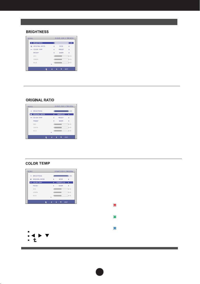
Main menu Sub menu Description
To adjust the brightness of the screen.
Exit : Exit
, , : Move
: Select another sub-menu
WIDE
ORIGINAL
PRESET
USER
Switch to full screen mode according to
input image signal.
Change the input image signal ratio to
original.
* This function works only if input
resolution is lower than monitor ratio
(16:9).
Select the screen color.
• WARM: Set the screen to warm color
temperature .
• MEDIUM: Set the screen to medium
color temperature.
• COOL: Set the screen to cool color
temperature.
RED
Set your own red color levels.
GREEN
Set your own green color levels.
BLUE
Set your own blue color levels.
12
Page 14

On Screen Display(OSD) Selection and Adjustment
Main menu Sub menu Description
To adjust the contrast of the screen.
To choose the language in which the
control names are displayed.
Exit : Exit
, , : Move
: Select another sub-menu
Restore all factory default settings except
"LANGUAGE."
Press the , buttons to reset
immediately.
13
Page 15

On Screen Display(OSD) Selection and Adjustment
You were introduced to the procedure of selecting and adjusting an item
using the OSD system. Listed below are the icons, icon names, and icon
descriptions of the all items shown on the Menu.
Press the SUPER ENERGY SAVING Button, then the main menu of the OSD appears.
Menu Name
Sub-menus
Icons
Button
Tip
Exit
Move
Restart to select sub-menu
NOTE
OSD (On Screen Display) menu languages on the monitor may differ from the manual.
14
Page 16

On Screen Display(OSD) Selection and Adjustment
Main menu Sub menu Description
ON
OFF
RESET
Turn on the SUPER ENERGY
SAVING fuction.
When current setting value is
ON,the SUPER SAVING color is
green.
Turn off the SUPER ENERGY
SAVING function.Now the monitor
is LED SAVING function.
When current setting value is
OFF,the SUPER SAVING color is
gray.
Clear the TOTAL POWER
REDUCTION and TOTAL CO2
REDUCTION values.
Exit : Exit
, : Move
: Select another sub-menu
OK : Select
TOTAL POWER REDUCTION : How much power is saved during using the monitor.
TOTAL CO2 REDUCTION : Change the TOTAL POWER REDUCTION to CO2.
15
Page 17

On Screen Display(OSD) Selection and Adjustment
NOTE
SAVING DATA(W/h):
19 inch
SUPER SAVING
LED SAVING
Saving Data depends on the Panel. So,those values should be different from
each panel and panel vendor.
LG accumulate those values using integrated function with 10 minutes
broadcast video signal.
LED Saving means that how much power can be saved using WLED Panel
instead of CCFL panel.
SUPER Saving means that how much power can be more saved using
SUPER ENERGY SAVING function.
3
3
16
Page 18

Troubleshooting
Check the following before calling for service.
No image appears
No image appears
● Is the power cord of the
display connected?
● Is the power indicator
light on?
● Is the power indicator
flickering?
● Do you see an "OUT OF
RANGE" message on
the screen?
● Do you see a "CHECK
SIGNAL CABLE"
message on the
screen?
•
Check and see if the power cord is connected
properly to the power outlet.
•
Press the Power button.
•
If the display is in power saving mode, try moving
the mouse or pressing any key on the keyboard to
bring up the screen.
• Try to turn on the PC
•
This message appears when the signal from the
PC (video card) is out of horizontal or vertical
frequency range of the display. See the
'Specifications' section of this manual and
configure your display again.
•
This message appears when the signal cable
between your PC and your display is not
connected. Check the signal cable and try again.
.
Do you see a "OSD LOCKED" message on the screen?
●
Do you see “OSD
LOCKED” when you
push MENU button?
• You can secure the current control settings,
so that they cannot be inadvertently changed.
You can unlock the OSD controls at any time
by pushing the MENU button for several
seconds: the message
“OSD UNLOCKED” will appear.
17
Page 19
Troubleshooting
Display image is incorrect
● Display Position is
incorrect.
● On the screen
background, vertical
bars or stripes are
visible.
● Any horizontal noise
appearing in any
image or characters
are not clearly
portrayed.
•
Press the AUTO button to automatically adjust
your display image to the ideal setting.
If the results are unsatisfactory, adjust the image
position using the H position and V position icon
in the on screen display.
•
Press the AUTO button to automatically adjust
your display image to the ideal setting.
If the results are unsatisfactory, decrease the
vertical bars or stripes using the CLOCK icon in
the on screen display.
•
Press the AUTO button to automatically adjust
your display image to the ideal setting.
If the results are unsatisfactory, decrease the
horizontal bars using the PHASE icon in the on
screen display.
•
Check Control Panel --> Display --> Settings
and adjust the display to the recommended
resolution or adjust the display image to the ideal
setting. Set the color setting higher than 24 bits
(true color).
IMPORTANT
Check Control Panel --> Display --> Settings and see if the frequency or the
resolution were changed. If yes, readjust the video card to the recommend
resolution.
If the recommended resolution (optimal resolution) is not selected, letters may be
blurred and the screen may be dimmed, truncated or biased. Make sure to select
the recommend resolution.
The setting method can differ by computer and O/S (Operation System),
and resolution mentioned above may not be supported by the video card
performance. In this case, please ask to the computer or the video card
manufacturer.
18
Page 20

Troubleshooting
Display image is incorrect
● The screen color is
mono or abnormal.
● The screen blinks.
•
Check if the signal cable is properly connected
and use a screwdriver to fasten if necessary.
•
Make sure the video card is properly inserted in
the slot.
•
Set the color setting higher than 24 bits (true color)
at Control Panel - Settings.
•
Check if the screen is set to interlace mode and if
yes, change it to the recommend resolution.
Do you see an "Unrecognized monitor, Plug&Play (VESA DDC) monitor found" message?
●
Have you installed the
display driver?
•
Be sure to install the display driver from the display
driver CD (or diskette) that comes with your
display. Or, you can also download the driver from
our web site: http://www.lg.com.
Make sure to check if the video card supports
•
Plug&Play function.
19
Page 21

Specifications
19EB13T
Display
Sync Input
Video Input
Resolution
Plug&Play
Power
Consumption
Dimensions
& Weight
47.0 cm (18.5 inch) Flat Panel Active matrix-TFT LCD
Anti-Glare coating
47.0
Visible diagonal size :
.
300 mm x 0.300 mm (Pixel pitch)
0
Horizontal Freq. 30 kHz to 61 kHz (Automatic)
Vertical Freq. 56 Hz to 75 Hz (Automatic)
Input Form Separate Sync.
Signal Input 15 pin D-Sub Connector
Input Form RGB Analog (0.7 Vp-p/ 75 ohm), Digital
Max VESA 1366 x 768 @ 60 Hz
Recommend VESA 1366 x 768 @ 60 Hz
DDC 2B(Digital),DDC 2AB(Analog)
On Mode
Sleep Mode < 0.3 W
Off Mode < 0.3 W
With Stand
Width 44.26 cm ( 17.42 inch)
Height 35.62 cm ( 14.02 inch)
Depth 16.99 cm ( 6.68 inch)
cm
Digital
DVI-D Connector (Digital)
18 W(Typ.)
:
Without Stand
Width 44.26 cm ( 17.42 inch)
Height 26.67 cm (10.50 inch)
Depth 6.04 cm ( 2.37 inch)
Weight(excl. packing) 2.8 kg (6.22 lb)
Range
Power Input
Environment
al Conditions
Stand Base
Power cord
NOTE
Information in this document is subject to change without notice.
Tilt : -5˚ to 15˚
AC 100 - 240 V~ 50 / 60 Hz 0.8 A
Operating Conditions
Temperature 10 ˚C to 35 ˚C
Humidity 10 % to 80 % non-Condensing
Storage Conditions
Temperature -20 ˚C to 60 ˚C
Humidity 5 % to 90 % non-Condensing
Attached ( ), Detached ( O )
Wall-outlet type
20
Page 22

Specifications
Preset Modes (Resolution)
19EB13T
*If you can't select 1366 x 768 in display property timing option, please
update your video card driver from your video card vendor.
Display Modes (Resolution) Horizontal Freq. (kHz) Vertical Freq. (Hz)
1
2
3
4
5
6
7
*8
720 x 400
640 x 480
640 x 480
800 x 600
800 x 600
832 x 624
1024 x 768
1366 x 768
31.468
31.469
37.500
37.879
46.875
49.725
48.363
47.712
70
60
75
60
75
75
60
60
*Recommend Mode
Indicator
MODE
On Mode
Sleep Mode
Off Mode
LED Color
White
White Blinking
Off
Polarity(H/V)
-/+
-/-
-/+/+
+/+
-/-
-/+/+
21
Page 23
Installing the Wall mount plate
This monitor satisfies the specifications of the Wall mount plate or
the interchange device.
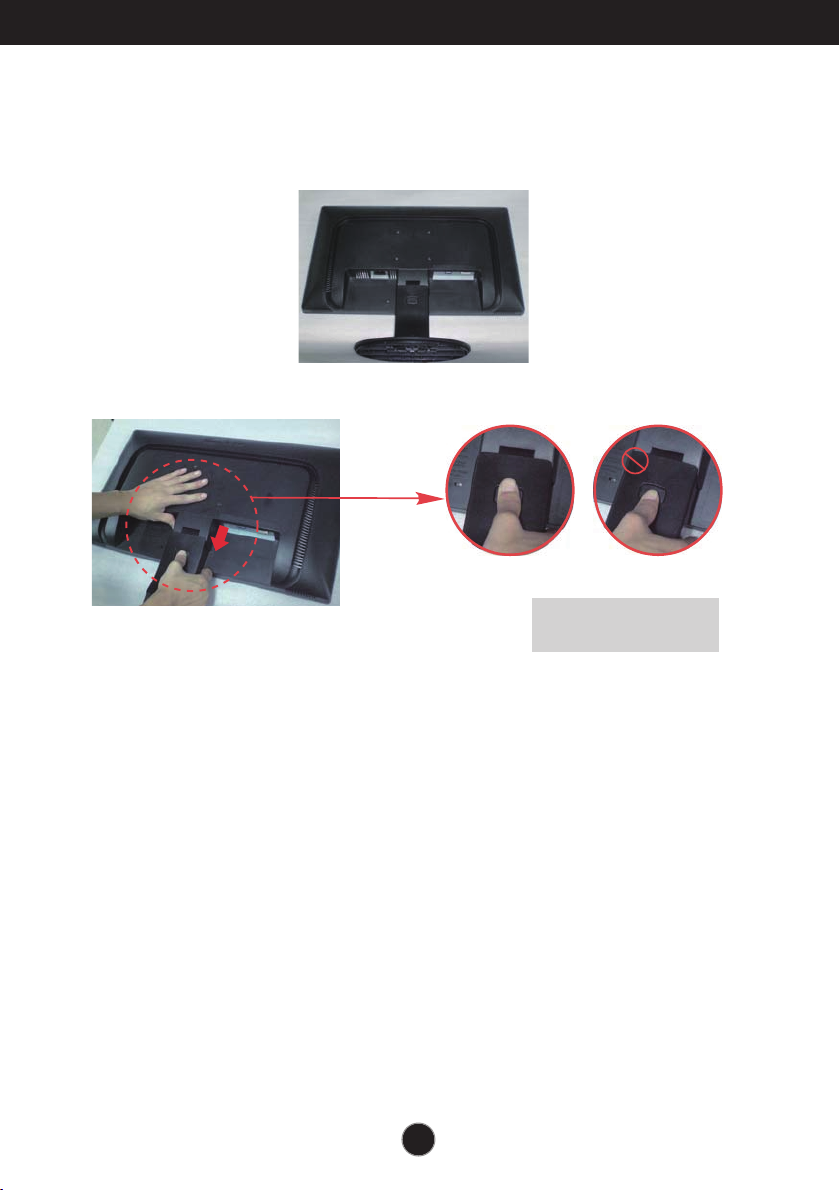
1. Place the monitor with its front facing downward on a soft cloth.
2. Separate the stand by pushing the PUSH button.
Good Position Bad Position
22
Warning:
You can hurt your finger.
Page 24

Installing the Wall mount plate
3.
Install the Wall mount plate.
Wall mount plate(Separate purchase)
This is stand-type or wall mount type and is
connectable with Wall mount plate.
Please refer to the installation guide for more
details, which is provided when Wall mount plate
is purchased.
Wall Mount pad
<Screw Mounting Interface Dimension>
Hole spacing : 75 mm x 75 mm.
Kensington Security Slot
Connected to a locking
cable that can be
purchased separately at
most computer stores.
NOTE
VESA compatible only with respect to screw mounting interface dimensions and mounting screw
specifications
Please use VESA standard as below.
* 784.8 mm and under (30.9 inch)
- Wall Mount Pad Thickness : 2.6 mm
- Screw : 4.0 mm x Pitch 0.7 mm x Length 10 mm
* 787.4 mm and above (31.0 inch)
- Please use VESA standard wall mount pad and screws.
23
Page 25

Declaration of Conformity
Trade Name: LG
Model : 19EB13TW
Responsible Party: LG Electronics Inc.
Address : 1000 Sylvan Ave. Englewood Cliffs
NJ 07632 U.S.A
TEL: 201-266-2534
*above information is only for USA FCC Regulatory
Make sure to read the Safety Precautions
before using the product.
Keep the OWNER’S MANUAL(CD) in an
accessible place for furture reference.
The model and serial number of the SET is
located on the back or one side of the SET.
Record it below should you ever need service.
MODEL
SERIAL
ENERGY STAR is a set of power-saving
guidelines issued by the U.S.Environmental
Protection Agency(EPA).
As an ENERGY STAR Partner LGE U. S. A.,Inc.
has determined that this product meets the
ENERGY STAR guidelines for energy efficiency.
 Loading...