

Page 1
LCD TV
Please read this manual carefully before operating your set.
Retain it for future reference.
Record model number and serial number of the set.
See the label attached on the back cover and quote
this information to your dealer when you require service.
OWNER’S MANUAL
MODELS: 15LS1R
*
20LS1R
*
20LS2R
*
23LS2R
*
15LC1R
*
20LC1R
*
Downloaded From TV-Manual.com Manuals
Page 2

Contents
Installation 3
Location and function of controls 8
Remote control handset
Battery installation / Front / Rear
Basic operation 14
On and off
On-Screen Menu Language/Country Selection
On screen menus 15
Menu selection / Programme selection
Volume adjustment
Setting up TV stations 16
Auto programme tuning
Manual programme tuning
Programme edit / Favourite programme
Calling the programme table
Picture adjustment 21
PSM (Picture Status Memory)
Picture adjustment
CSM (Colour Status Memory)
XD function / Cinema / Reset
Sound adjustment 25
SSM (Sound Status Memory)
Sound adjustment / Stereo/Dual reception
NICAM reception / Sound output selection
Time Menu 27
Clock / On/Off time
Auto sleep / Sleep timer
Other functions 29
Child lock / XD Demo
TV, AV and PC modes / Auto AV switching
Teletext 32
Switch on/off
SIMPLE text / TOP text
FASTEXT / Special teletext functions
Connection of external equipment 34
Aerial socket /
Euro scart socket (VCR)
Audio/Video in sockets
S-Video/Audio in sockets (S-Video)
DVD input sockets
DTV in sockets /
Headphone socket
Connection of PC 37
PC in socket
PC Setup
Selecting wide XGA mode
Picture format 40
Troubleshooting checklist 41
Product Specifications 43
2
Downloaded From TV-Manual.com Manuals
Page 3
3
ENGLISH
Installation
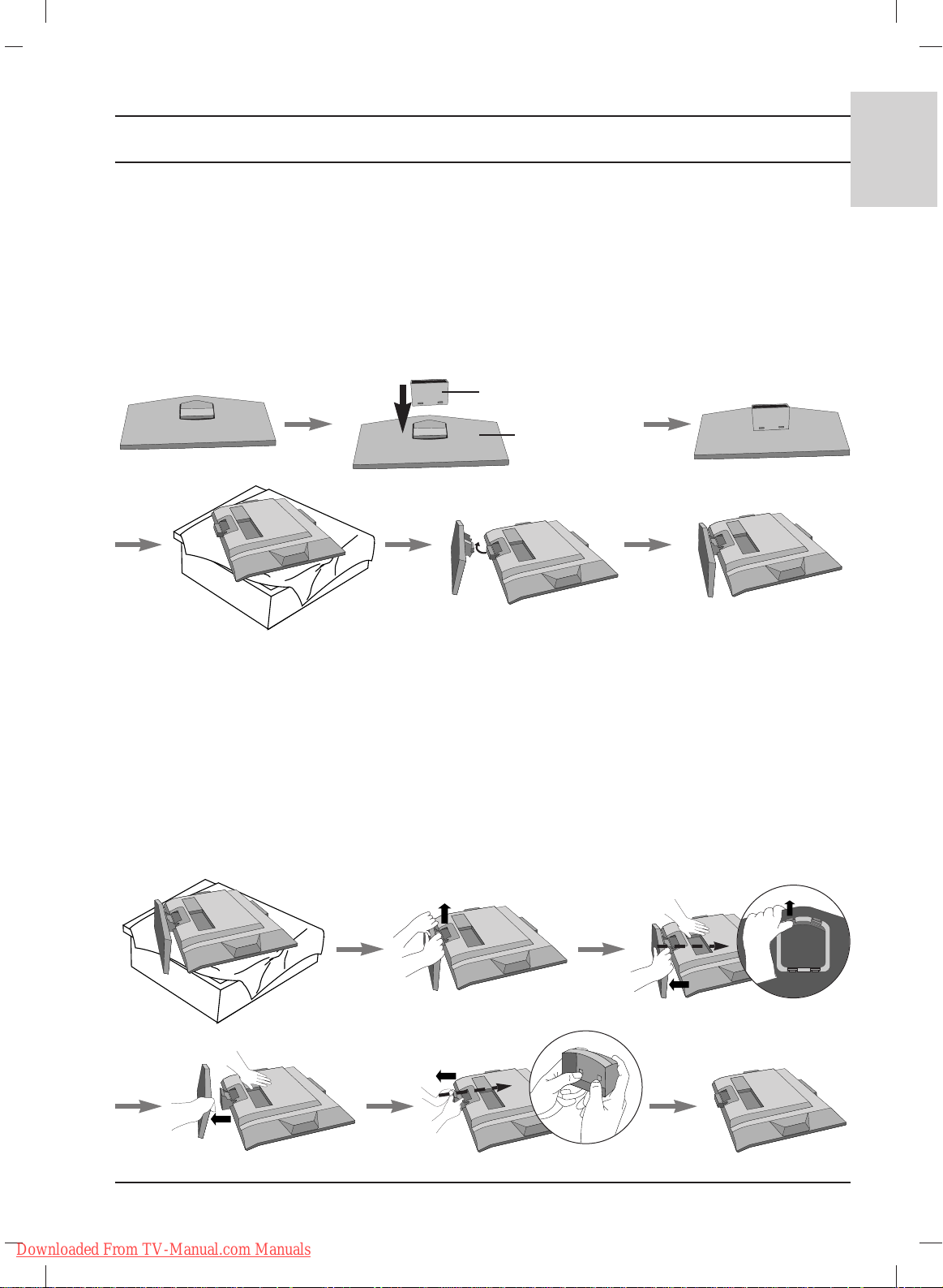
Stand Installation
1. Assemble parts of stand body with cover base of the stand. Insert stand body into a cover base
until clicking sound.
2. Carefully place the product screen side down on a cushioned surface that will protect product
and screen from damage.
3. Place the product stand on the product as shown.
Note: Here shown may be somewhat different from your set.
stand body
cover base
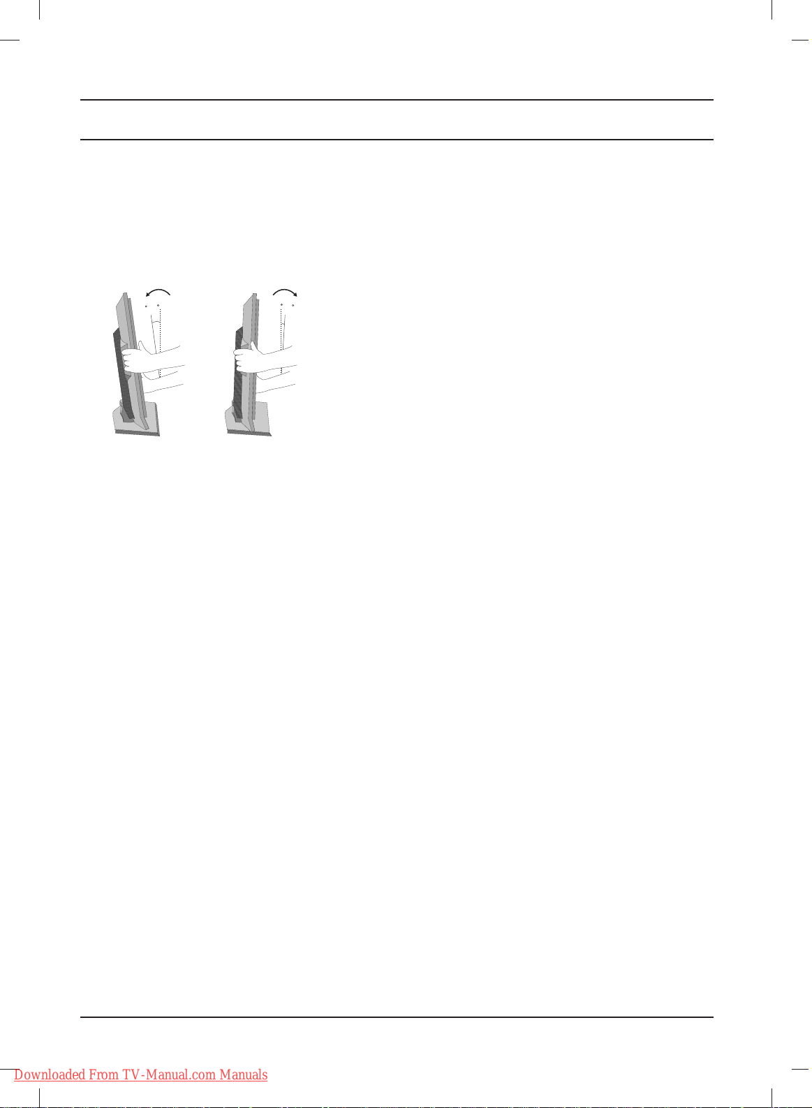
Detaching stand
1. Place the set with its front facing downward on a cushion or soft cloth.
2. Hold the stand with both hands and bend it upward.
3. Pull each side of cover base backward during pressing latch upward.
4. Hold cover base and pull with shake it backward to separate from stand body.
5. Pull stand body to separate from set during pressing 2 latches.
Note: Here shown may be somewhat different from your set.
Downloaded From TV-Manual.com Manuals
Page 4
Installation
4
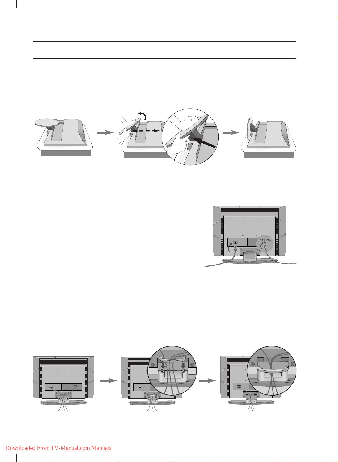
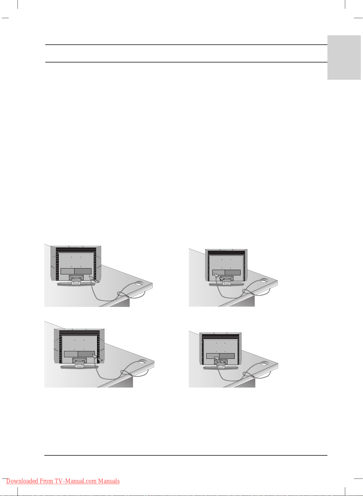
Basic connection
1. Connect the cables as necessary.
To connect an additional equipment,see the Connection of external equipment section.
2. Install the Cable management as shown.
Note: Here shown may be somewhat different from your set.
Connection of TV
1. Connect the aerial cable to the socket marked ANTENNA IN
on the back. For the best reception an outdoor aerial should
be used.
2. To connect an additional equipment, see the Connection of
external equipment section.
3. Connect the power cord.
Note: Here shown may be somewhat different from your set.
( )
The stand won't move if you
don't press release button.
Unfolding the stand base
1. Place the set with its front facing downward on a cushion or soft cloth.
2. Hold down the release button inside the stand and strongly pull out the stand with your two hands.
Note: Here shown may be somewhat different from your set.
Downloaded From TV-Manual.com Manuals
Page 5
5
ENGLISH
Installation
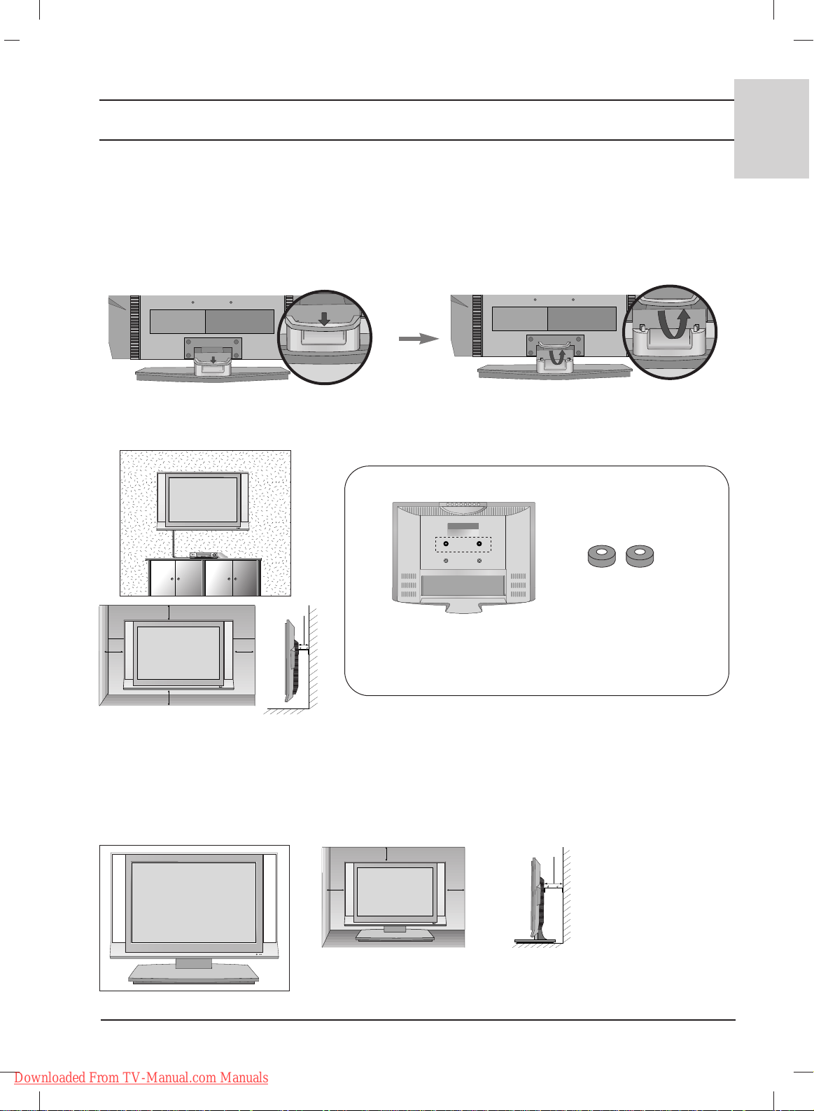
How to remove the Cable management
First, press the cable management.
Hold the Cable management with both hands and pull it upward.
Note: Do not hold the CABLE MANAGEMENT when moving the product. (If the product is dropped,you
may be injured or the product may be broken.)
Wall Mount: Horizontal installation
4 inches
4 inches
4 inches
4 inches
4 inches
R
R
For proper ventilation, allow a clearance of 4" on each side and from the wall. Detailed installation
instructions are available from your dealer, see the optional Tilt Wall Mounting Bracket Installation and
Setup Guide.
For proper ventilation, allow a clearance of 4" on each side and
from the wall.
4 inches
4 inches
4 inches
4 inches
R
Desktop Pedestal Installation
Place the ring spacers on the set before installing the
wall mounting bracket so that the inclination of the
backside of the set can be adjusted perpendicularly.
2-Ring spacers
< 20LC1R*only >
Downloaded From TV-Manual.com Manuals
Page 6
6
Installation
Positioning your display
Adjust the position of the panel in various ways for maximum comfort.
10~12
3
0
• Tilt range
Location
Position your set so that no bright light or sunlight falls directly onto the screen. Care should be taken
not to expose the set to any unnecessary vibration, moisture, dust or heat. Also ensure that the set is
placed in a position to allow a free flow of air. Do not cover the ventilation openings on the back cover.
If you intend to mount the TV to a wall, attach
VESA standard mounting interface
(optional parts) to the
back of the TV.
When you install the set to use the wall mounting bracket (optional parts), fix it carefully so as not to drop.
Downloaded From TV-Manual.com Manuals
Page 7
Installation
7
ENGLISH
Kensington Security System
- The TV is equipped with a Kensington Security System connector on the back panel. Connect the
Kensington Security System cable as shown below.
- For the detailed installation and use of the Kensington Security System, refer to the user’s guide
provided with the Kensington Security System.
For further information, contact http://www.kensington.com, the internet homepage of the
Kensington company. Kensington sells security systems for expensive electronic equipment such as
notebook PCs and LCD projectors.
Note:
- The Kensington Security System is an optional accessory.
Note:
a. If the TV feels cold to the touch, there may be a small “flicker” when when it is turned on.
This is normal, there is nothing wrong with TV.
b. Some minute dot defects may be visible on the screen, appearing as tiny red, green, or blue spots.
However, they have no adverse effect on the monitor's performance.
c. Avoid touching the LCD screen or holding your finger(s) against it for long periods of time.
Doing so may produce some temporary distortion effects on the screen.
d. Here shown may be somewhat different from your set.
Downloaded From TV-Manual.com Manuals
Page 8
8
Location and function of controls
[without ARC]
123
456
879
0
OK
LIST
MUTE
VOL
HOLD SIZE MIX TIME
REVEAL MODE
UPDATE
INDEX
VOL
PR
PR
TEXT
PSM SSM
Q.VIEW
POWER
TV INPUT
M
ENU
SLEEP
I/II
A
R
C
?
i
M
10
12
13
14
15
9
3
4
5
6
7
8
1
2
11
16
13
[with ARC]
[with ARC]
OK
MUTE
VOL VOL
PR
PR
TEXT
PSM SSM
M
ENU
SLEEP
I/II
*
[without ARC]
SSM PSM
0
SLEEP TEXT
UPDATE
TIME
SIZE MIX
HOLD
REVEAL
INDEX MODE
?
i
M
*
5 1
14
7
13
4
10
9
3
11
6
2
12
15
8
16
13
/
10
14
12
11
13
15
2
3
7
16
6
4
5
9
1
8
TV INPUT I/II
POWERMUTE
LIST
Q.VIEW MENU
PR
OK
VOL
PR
123
456
789
SSM PSM
0
SLEEP ARC TEXT
UPDATE
SIZE MIX
HOLD
INDEX MODE
i
VOL
TIME
REVEAL
?
M
Downloaded From TV-Manual.com Manuals
Page 9
9
ENGLISH
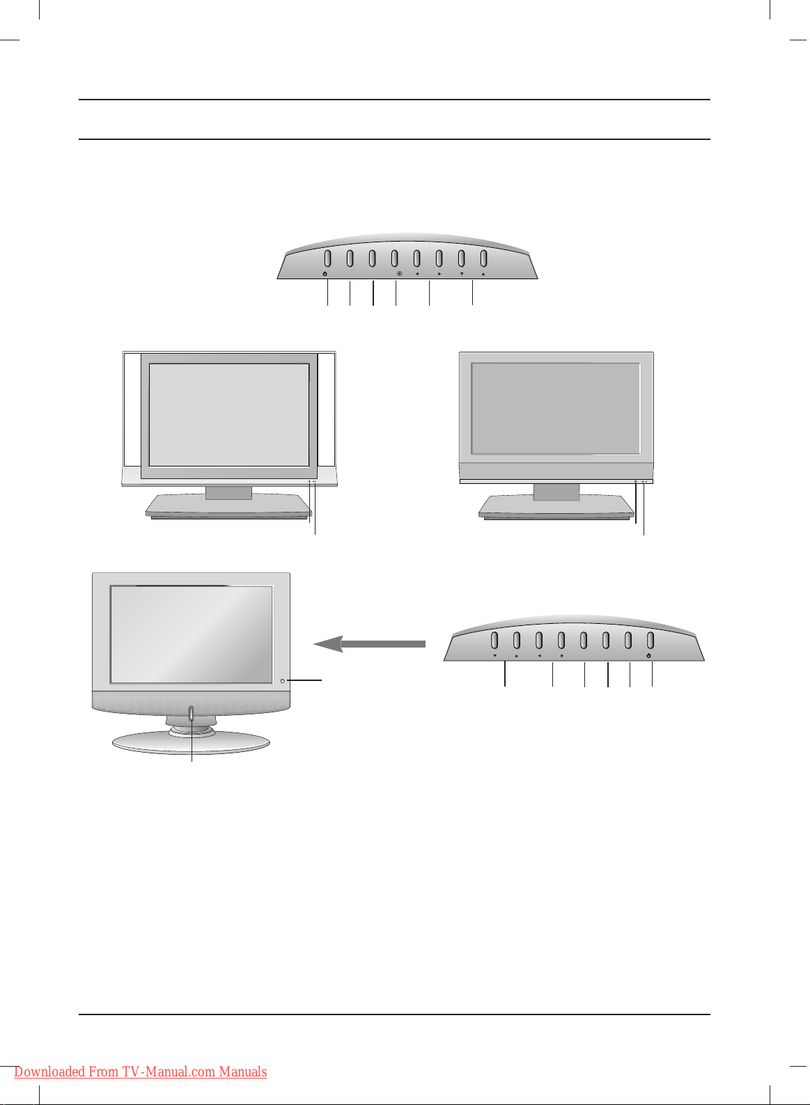
Location and function of controls
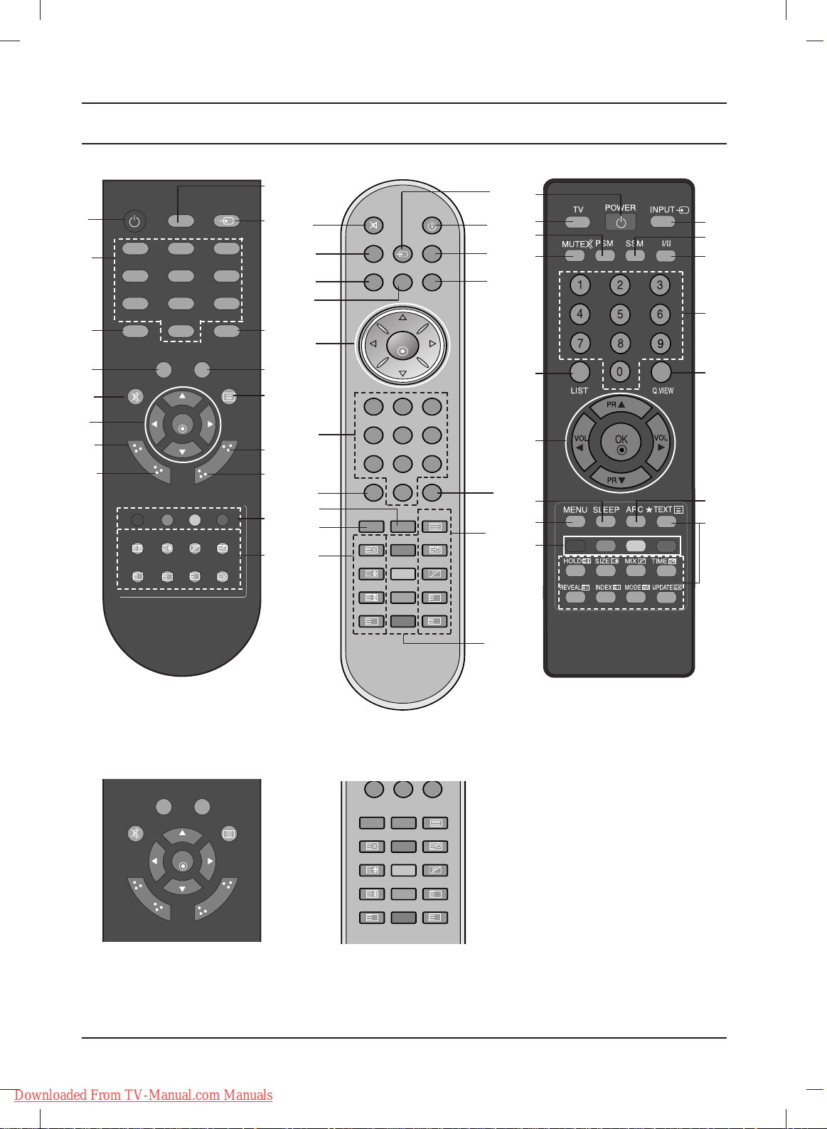
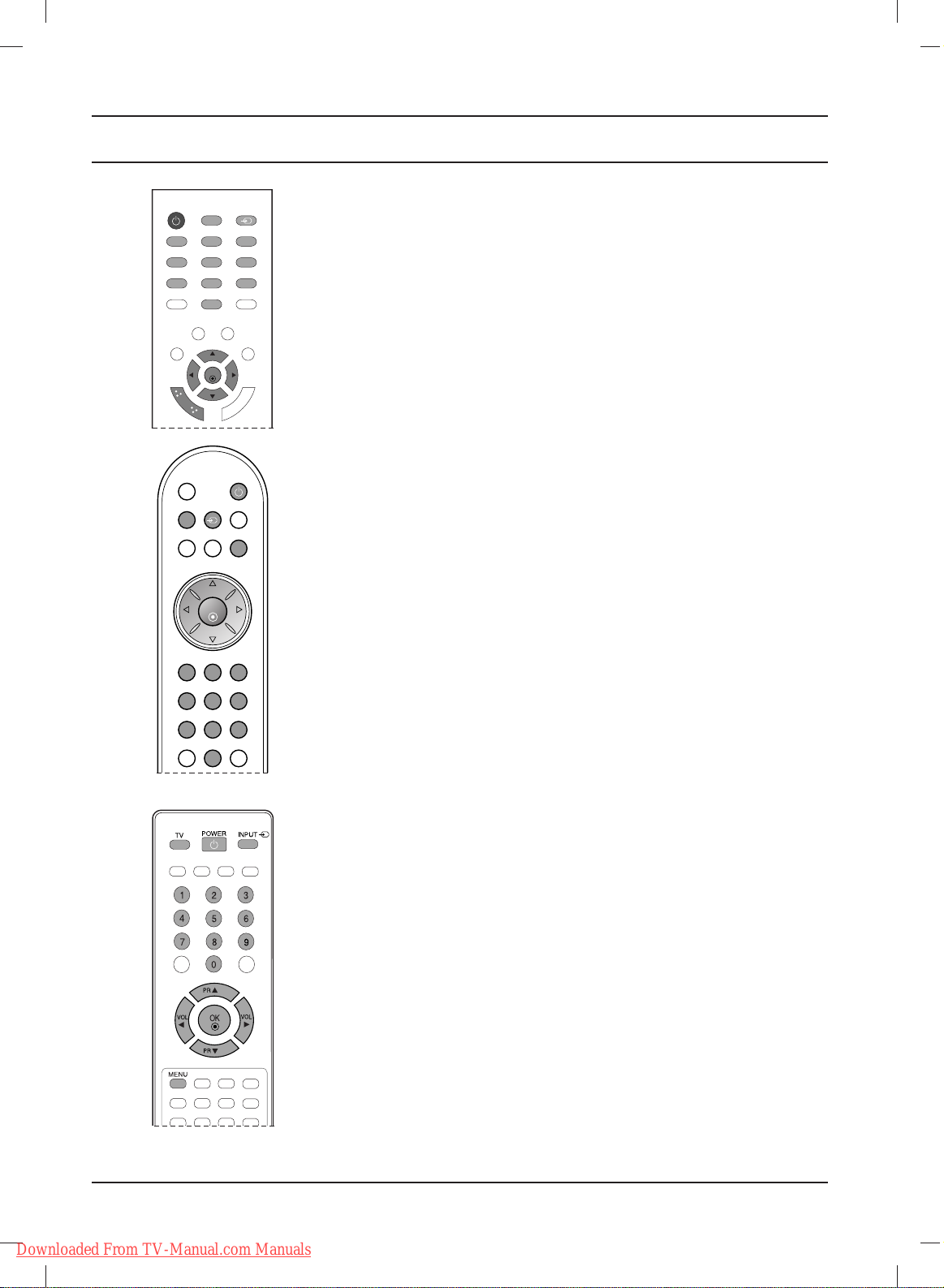
All the functions can be controlled with the remote
control handset. Some functions can also be
adjusted with the buttons on the top panel of the
set. Only the remote control handset supplied will
operate this set.
Remote control handset
Before you use the remote control handset,
please install the
batteries. See the next page.
1. POWER
switches the set on from standby or off to
standby.
2. NUMBER BUTTONS
switches the set on from standby and selects
a programme.
3. LIST
displays the programme table.
4. PSM (Picture Status Memory)
recalls your preferred picture setting.
5. MUTE
switches the sound on or off.
Press the MUTE button. The sound is
switched off and the display appears.
You can cancel it by pressing the MUTE,
FF / GG
,
I/II,orSSM button.
6.
DD / EE
(Programme Up/Down)
selects a programme or a menu item.
switches the set on from standby.
FF / GG
(Volume Down/Up)
adjusts the volume.
adjusts menu settings.
OK
accepts your selection or displays the current
mode.
7. MENU
selects a menu.
8. SLEEP
sets the sleep timer.
9. TV
returns to the TV mode.
switches the set on from standby.
10. INPUT
selects the remote operating mode.
switches the set on from standby.
11. Q.VIEW
returns to the previously viewed programme.
Press the Q.VIEW button to view the last programme you were watching.
12. SSM (Sound Status Memory)
recalls your preferred sound setting.
13. TELETEXT BUTTONS
These buttons are used for teletext.
For further details, see the ‘Teletext’ section.
14. I/II
selects the language during dual language
broadcast.
15. ARC (20LS2R*/ 23LS2R*)
select your desired picture format.
16. COLOURED BUTTONS : These buttons are
used for teletext (only TELETEXT models) or
programme edit.
*
: No function
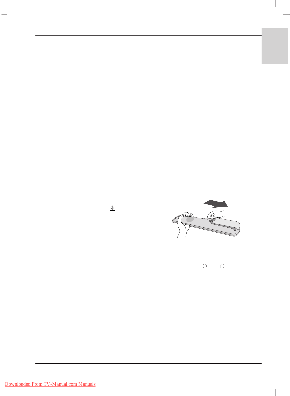
Battery installation
Note : To avoid damage from possible battery
leakage, remove the batteries if you do not plan to
use the remote control handset for an extended
period of time.
The remote control handset is powered by two
AAA batteries. To load the batteries, turn the
remote control handset over and open the battery
compartment. Install two batteries as indicated by
the polarity symbols ( and ) marked inside
the compartment.
+
-
Downloaded From TV-Manual.com Manuals
Page 10
10
Location and function of controls
8
7
8
7
1. ON/OFF (rr / I)
switches the set on from standby or off to
standby.
2. INPUT
selects the remote operating mode.
switches the set on from standby.
3. MENU
selects a menu.
4. OK
accepts your selection or displays the current
mode.
5. FF / GG (Volume Down/Up)
adjusts the volume.
adjusts menu settings.
6. EE / DD (Programme Down/Up)
selects a programme or a menu item.
switches the set on from standby.
7. REMOTE CONTROL SENSOR
8. POWER/STANDBY INDICATOR
- 15LS1R*/ 20LS1R*/ 20LS2R*/ 23LS2R
*
illuminates red in standby mode.
illuminates green when the set is switched on.
-
15LC1R*/ 20LC1R
*
illuminates orange in standby mode.
illuminates blue when the set is switched on.
INPUT
MENU
VOL
PR
/I
OK
Front
1 2
3 4 5
6
15LS1R*/ 20LS1R
*
15LC1R*/ 20LC1R
*
20LS2R*/ 23LS2R
*
7
8
Top panel
INPUT
MENU
VOL
PR OK
/I
6 5
4 3 2
1
If your product has a protection film attached, remove the film and then wipe the product with a polishing
cloth.
Top panel
Downloaded From TV-Manual.com Manuals
Page 11
Location and function of controls
11
ENGLISH
H/P
RGB(PC/DTV) IN
ANTENNA IN
AUDIO
(RGB) IN
S-VIDEO
AV IN 2
VIDEO
H/P
SERVICE ONLY
ANTENNA IN
S-VIDEO
AV IN 2
VIDEO
AV 1
AV 1
15LS1R
*
20LS1R
*
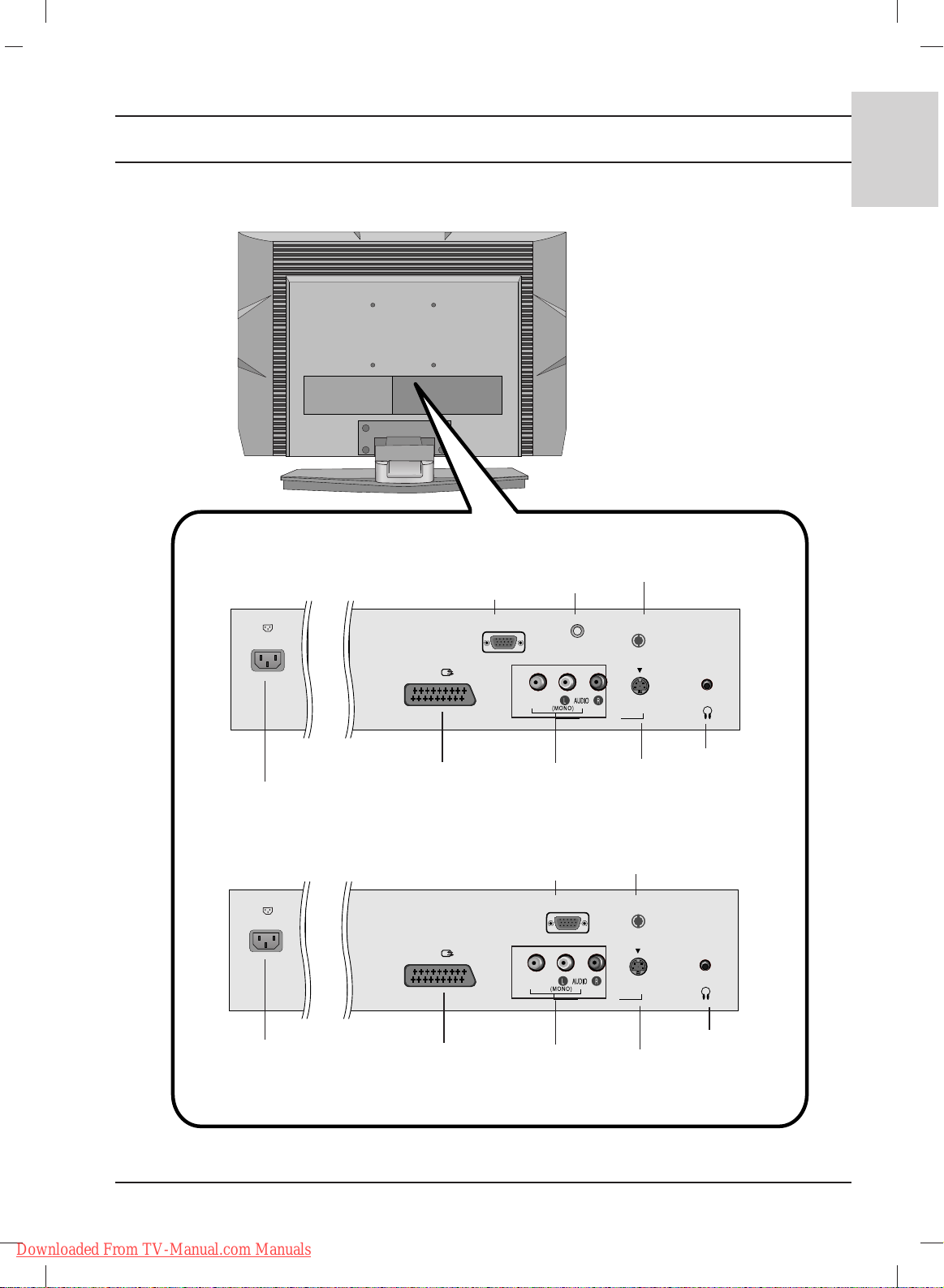
Rear
AC INPUT
AUDIO/VIDEO
INPUT
PC INPUT
JACK
PC SOUND
INPUT
ANTENNA
INPUT
EURO SCART
SOCKET
S-VIDEO
INPUT
HEADPHONE
JACK
AC INPUT
AUDIO/VIDEO
INPUT
FOR SERVICE
JACK
ANTENNA
INPUT
EURO SCART
SOCKET
S-VIDEO
INPUT
HEADPHONE
JACK
Downloaded From TV-Manual.com Manuals
Page 12
12
Location and function of controls
H/P
RGB
(PC/DTV) IN
ANTENNA IN
AUDIO
(RGB/DVI) IN
AV 1
S-VIDEO
AV IN 2
VIDEO
LR
AUDIO
YP
B PR LR
VIDEO
COMPONENT IN
AUDIO
HDMI/DVI IN
H/P
RGB
(PC/DTV) IN
ANTENNA IN
AUDIO
(RGB/DVI) IN
AV 1
S-VIDEO
AV IN 2
VIDEO
LR
AUDIO
YP
B PR LR
VIDEO
COMPONENT IN
AUDIO
HDMI/DVI IN
RS-232C
(SERVICE ONLY)
20LS2R*/ 23LS2R
*
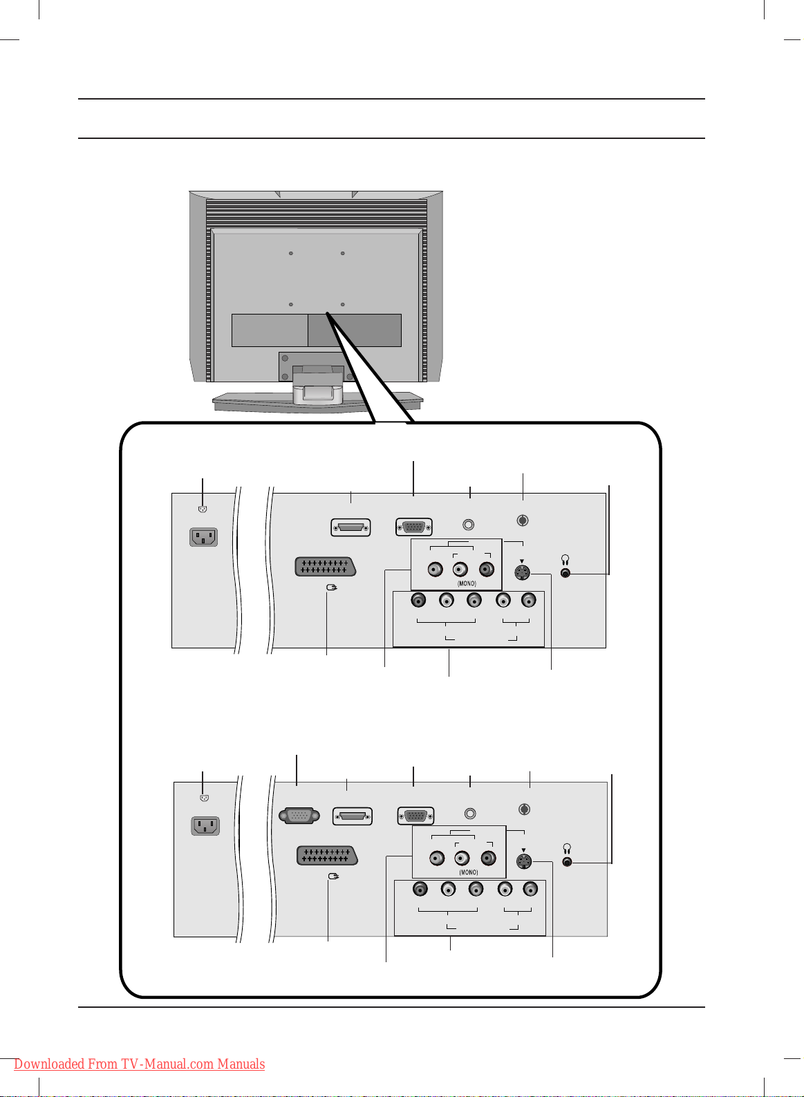
Rear
AC INPUT
AUDIO/VIDEO
INPUT
HDMI/DVI
INPUT
PC INPUT
JACK
EURO SCART
SOCKET
COMPONENT
INPUT
PC SOUND
INPUT
ANTENNA
INPUT
HEADPHONE
JACK
S-VIDEO
INPUT
20LS2RC
AC INPUT
AUDIO/VIDEO
INPUT
HDMI/DVI
INPUT
PC INPUT
JACK
EURO SCART
SOCKET
COMPONENT
INPUT
PC SOUND
INPUT
ANTENNA
INPUT
HEADPHONE
JACK
S-VIDEO
INPUT
RS-232C
(SERVICE ONLY)
Downloaded From TV-Manual.com Manuals
Page 13
13
ENGLISH
Location and function of controls
H/P
RGB(PC/DTV) IN
ANTENNA IN
AUDIO
(RGB) IN
S-VIDEO
AV IN 2
VIDEO
H/P
SERVICE ONLY
ANTENNA IN
S-VIDEO
AV IN 2
VIDEO
AV 1
AV 1
15LC1R
*
20LC1R
*
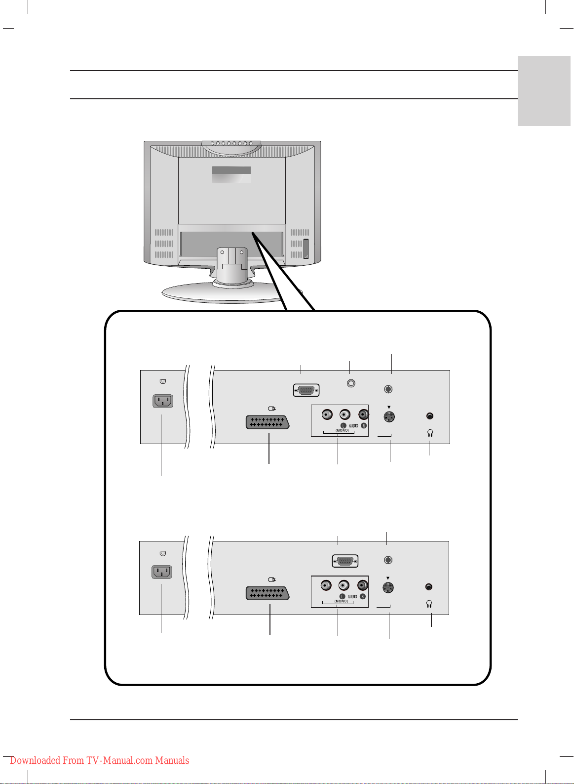
Rear
AC INPUT
AUDIO/VIDEO
INPUT
PC INPUT
JACK
PC SOUND
INPUT
ANTENNA
INPUT
EURO SCART
SOCKET
S-VIDEO
INPUT
HEADPHONE
JACK
AC INPUT
AUDIO/VIDEO
INPUT
FOR SERVICE
JACK
ANTENNA
INPUT
EURO SCART
SOCKET
S-VIDEO
INPUT
HEADPHONE
JACK
Downloaded From TV-Manual.com Manuals
Page 14
14
Basic operation
On and off
1. Press the POWER,
DD / EE
, TV, INPUT or NUMBER buttons to
switch it on fully.
2. Press the POWER button. The set reverts to standby mode.
3. Pull out mains plugs to switch the set off.
Note : If, while the set is switched on, the mains plug is disconnected
the set will switch to standby or power on when the mains plug is
replaced in the mains power socket.
On-Screen Menu Language / Country Selection
Installation guide menu appears on TV screen when it is turned on for the
first time.
1.
Press the
DD
// EE// F//
G button and then, OK button to select your
desired language.
2. Press the
DD
// EE// F//
G button and then, OK button to select your
country.
* If you want to change Language/ Country selection
1. Press the MENU button and then
DD / EE
button to select the
SPECIAL menu.
2. Press the
GG
button and then
DD / EE
button to select Language.
The menus can be shown on the screen in the selected language.
Or,
Press the GGbutton and then
DD / EE
button to select Country.
3. Press the
GG
button and then
DD
// EE// F//
G
button to select your
desired language or country.
4. Press the OK button.
5. Repeatedly press the MENU button to return to normal TV
viewing.
Note:
a. If you don’t finish set up Installation Guide by pressing MENU
button or time out of OSD (On Screen Display) display, it will
continuously appear until completing set up whenever the set
is turned on.
b. If you select wrong local country, the teletext may not appear
correctly on the screen and some problem may happen during
teletext operation.
c. Hebrew is added to Country of Installation Guide according
to the countries which using Hebrew languages.
123
456
879
0
OK
LIST
MUTE
VOL VOL
PR
PR
TEXT
PSM SSM
Q.VIEW
POWER
TV INPUT
M
ENU
S
L
E
E
P
I/II
POWER
TV INPUT I/II
PR
PR
VOL
OK
123
456
789
SSM
0
VOL
MENU
Downloaded From TV-Manual.com Manuals
Page 15

15
ENGLISH
Menu selection
1. Press the MENU button and then
DD / EE
button to display each menu.
2. Press the GGbutton and then
DD / EE
button to select a menu item.
3. Change the setting of an item in the sub or pull-down menu with
FF / GG
button.
You can move to the higher level menu by pressing the OK
button and to move to the lower level menu by pressing the
MENU
button.
Note :
a. The SCREEN (20LS1R*/20LC1R*) menu is not displayed.
b. In the teletext mode, menus are not displayed.
c. On some models, the Language will not be displayed.
Programme selection
You can select a programme number with the
DD / EE
or NUMBER
buttons.
Volume adjustment
Press the
FF / GG
button to adjust the volume.
OK
MUTE
VOL VOL
PR
PR
TEXT
PSM SSM
M
EN
U
S
L
E
E
P
I/II
*
On screen menus
STATION menu
PICTURE menu
SOUND menu
SPECIAL menu
TIME menu
SCREEN menu
*
:
20LS2R*, 23LS2R
Screen
DE FG
OK MENU
Auto config.
Manual config.
XGA Mode*
ARC*
Reset
Station
DE FG
OK MENU
Auto programme
Manual programme
Programme edit
Favourite programme
Picture
DE FG
OK MENU
PSM
CSM
XD*
Cinema*
Reset
Sound
DE FG
OK MENU
SSM
AVL
Balance 0
Time
DE FG
OK MENU
Clock
Off time
On time
Auto sleep
Special
DE FG
OK MENU
Language
Country
Child lock
XD Demo*
PR
PR
VOL VOL
MENU
OK
Downloaded From TV-Manual.com Manuals
Page 16

16
Setting up TV stations
Up to 100 TV stations can be stored by programme numbers (0 to 99).
Once you have preset the stations, you will be able to use the
DD / EE
or NUMBER buttons to scan the stations you have programmed.
Stations can be tuned using automatic or manual modes.
Auto programme tuning
All stations that can be received are stored by this method. It is
recommended that you use auto programme during installation
of this set.
1. Press the MENU button and then
DD / EE
button to select the
Station menu.
2. Press the GGbutton and then
DD / EE
button to select Auto
programme.
3. Press the GGbutton. Select a TV system with the GGbutton and
then
DD / EE
button on the System menu;
BG : PAL B/G, SECAM B/G (Europe/East Europe)
I : PAL I/II (U.K./Ireland)
DK : PAL D/K, SECAM D/K (East Europe)
L : SECAM L/L’ (France)
4. Press the OK button.
5. Press the
DD / EE
button to select Storage from.
6. Select the beginning programme number with the
FF / GG
button
or NUMBER buttons on the Storage from pull-down menu. Any
number under 10 is entered with a numeric ‘0’ in front of it, i.e.
‘05’ for 5.
7. Press the OK button.
8. Press the
DD / EE
button to select Search.
9. Press the GGbutton to begin auto programming.
All receivable stations are stored.
To stop auto programming, press the MENU button.
When auto programming is completed, the Programme edit
menu appears on the screen. See the ‘Programme edit’ section
to edit the stored programme.
10.
Repeatedly press the MENU button to return to normal TV
viewing.
Auto programme
DE F G
OK MENU
System
Storage from
Search
G
To start
Auto programme
DE FG
OK MENU
System G
Storage from
Search
BG
I
DK
L
Auto programme
C 05 BG
5 35%
MENU Stop
123
456
879
0
LIST
VOL VOL
PR
PR
TEXT
PSM
Q.VIEW
M
ENU
S
L
E
I/II
MUTE
SSM
OK
Station
DE FG
OK MENU
Auto programme
Manual programme
Programme edit
Favourite programme
PR
PR
VOL VOL
MENU
123
456
789
0
OK
Downloaded From TV-Manual.com Manuals
Page 17

17
ENGLISH
Manual programme tuning
Manual programme lets you manually tune and arrange the
stations in whatever order you desire. Also you can assign a station
name with five characters to each programme number.
1. Press the MENU button and then
DD / EE
button to select the
Station menu.
2. Press the GGbutton and then
DD / EE
button to select Manual
programme.
3. Press the GGbutton and then
DD / EE
button to select Storage.
4. Select the desired programme number (0 to 99) with the
FF / GG
button or NUMBER buttons on the Storage menu. Any number
under 10 is entered with a numeric ‘0’ in front of it, i.e. ‘05’ for 5.
5. Press the OK button.
6. Press the
DD / EE
button to select System.
7. Select a TV system with the GGbutton and then
FF / GG
button on
the System menu;
BG : PAL B/G, SECAM B/G (Europe/East Europe)
I : PAL I/II (U.K./Ireland)
DK : PAL D/K, SECAM D/K (East Europe)
L : SECAM L/L’ (France)
8. Press the OK button.
9. Press the
DD / EE
button to select Band.
10. Press the GGbutton and then
DD / EE
button to select VHF/UHF or
Cable on the Band menu.
11. Press the OK button.
12.
Press the
DD / EE
button to select Channel.
13. Select the desired programme with
FF / GG
button or NUMBER
buttons.
14. Press the OK button.
15. Press the
DD / EE
button to select Search.
16. Press the GGbutton and then
FF / GG
button to commence search-
ing on the Search pull-down menu. If a station is found the search
will stop.
17. Press the OK button to store it.
18. To store another station, repeat steps 3 to 17.
19.
Repeatedly press the MENU button to return to normal TV
viewing.
Setting up TV stations
Manual programme
DE FG
OK MENU
Storage
G
System
Band
Channel
Fine
Search
Name
29
Manual programme
DE FG
OK MENU
Storage
System
Band
Channel
Fine
Search
G
Name
F /
GG
Station
DE F G
OK MENU
Auto programme
Manual programme
Programme edit
Favourite programme
123
456
879
0
LIST
VOL VOL
PR
PR
TEXT
PSM
Q.VIEW
M
E
NU
S
L
E
I/II
MUTE
SSM
OK
PR
PR
VOL VOL
MENU
123
456
789
0
OK
Downloaded From TV-Manual.com Manuals
Page 18

18
Setting up TV stations
Station
DE FG
OK MENU
Auto programme
Manual programme
Programme edit
Favourite programme
Assigning a station name
1. Repeat the ‘Manual programme tuning’ steps 1 to 2.
2. Press the GGbutton and then
DD / EE
button to select Name.
3. Press the GGbutton and then use the
DD / EE
. You can use a blank,
+, -, the number 0 to 9 and the alphabet A to Z. It can be saved 5
digits for name.
With the FFbutton you can select in the opposite direction.
4. Select the position by pressing the
FF / GG
button and then make
your choice of the second character, and so on.
5. Press the OK button to store it.
6.
Repeatedly press the MENU button to return to normal TV
viewing.
Fine tuning
Normally fine tuning is only necessary if reception is poor.
1. Repeat the ‘Manual programme tuning’ steps 1 to 2.
2. Press the
GG
button and then
DD / EE
button to select Fine.
3. Press the GGbutton
4. Press the
FF / GG
button to fine tune for the best picture and sound
on the Fine pull-down menu.
5. Press the OK button.
6. Repeatedly press the
MENU
button to return to normal TV
viewing.
The finely tuned programme will be indicated by orange number during programme selection.
Manual programme
DE FG
OK MENU
Storage
System
Band
Channel
Fine
G
Search
Name
F /
GG
879
0
OK
LIST
MUTE
VOL
HOLD SIZE MIX TIME
VOL
PR
PR
TEXT
PSM SSM
Q.VIEW
M
ENU
S
L
E
E
P
I/II
*
PR
PR
VOL
OK
VOL
MENU
Downloaded From TV-Manual.com Manuals
Page 19

19
ENGLISH
Programme edit
This function enables you to delete or skip the stored programmes.
Also you can move some stations to other programme numbers or
insert a blank station data into the selected programme number.
1. Press the MENU button and then
DD / EE
button to select the
Station menu.
2. Press the GGbutton and then
DD / EE
button to select Programme
edit.
3.
Press the GGbutton to display the
Programme edit menu.
Deleting a programme
1. Select a programme to be deleted with the
DD / EE
or
FF / GG
button.
2. Press the RED button twice.
The selected programme is deleted, all the following
programmes are shifted up one position.
Copying a programme
1. Select a programme to be copied with the
DD / EE
or
FF / GG
button.
2. Press the GREEN button.
All the following programmes are shifted down one position.
Moving a programme
1. Select a programme to be moved with the
DD / EE
or
FF / GG
button.
2. Press the YELLOW button.
3. Move the programme to the desired programme number with
the
DD / EE
or
FF / GG
button.
4. Press the YELLOW button again to release this function.
Skipping a programme number
1. Select a programme number to be skipped with the
DD / EE
or
FF / GG
button.
2. Press the BLUE button. The skipped programme turns to blue.
3. Press the BLUE button again to release the skipped programme.
When a programme number is skipped it means that you will be
unable to select it using the
DD / EE
button during normal TV
viewing. If you want to select the skipped programme, directly
enter the programme number with the NUMBER buttons or
select it in the programme edit or table menu.
Repeatedly press the
MENU
button to return to normal TV viewing.
Setting up TV stations
Programme edit
DE F G
OK MENU
Delete
Move
Copy
Skip
Programme edit
MENU
Delete
Station
DE F G
OK MENU
Auto programme
Manual programme
Programme edit
Favourite programme
0C03 5S69
1 BLN 03 6 S 17
2 C 12 7 S 22
3 S 66 8 C 09
4 S 67 9 C 11
0C03 5S69
1 BLN 03 6 S 17
2 C 12 7 S 22
3 S 66 8 C 09
4 S 67 9 C 11
123
456
879
0
LIST
VOL
VOL
PR
PR
TEXT
PSM
Q.VIEW
M
E
N
U
SLEEP
I/II
*
MUTE
SSM
OK
PR
PR
VOL
OK
VOL
MENU
123
456
789
0
Downloaded From TV-Manual.com Manuals
Page 20

20
Setting up TV stations
Favourite programme
This function lets you select your favourite programmes directly.
1.
Press the MENU button and then
DD / EE
button to select the
Station menu.
2. Press the GGbutton and then
DD / EE
to select Favourite
programme.
3. Press the
GG
button a
nd then
FF / GG
button to select On or Off.
4. Press the
DD / EE
button to select -- -----.
5. Select a desired programme with the
FF / GG
button.
6. To store another programme, repeat steps 4 to 5.
You can store up to 8 programmes.
7.
Repeatedly press the MENU button to return to normal TV viewing.
Repeatedly press the YELLOW button to select stored favourite
programmes while it is selected On. Repeatedly press the YEL-
LOW button to select previous programmes while it is selected Off.
Calling the programme table
You can check the programmes stored in the memory by displaying
the programme table.
Displaying programme table
Press the LIST button to display the Programme table menu.
The programme table appears on the screen. One programme
table contains ten programmes as below.
Note :
a. You may find some blue programmes. They have been set up to
be skipped by auto programming or in the programme edit mode.
b. Some programmes with the channel number shown in the
programme table indicate there is no station name assigned.
Selecting a programme in the programme table
Select a programme with the
DD / EE
or
FF / GG
button.
Then press the OK button.
The set switches to the chosen programme number.
Paging through a programme table
There are 10 programme table pages in which contain 100
programmes.
Pressing the
DD / EE
or
FF / GG
button repeatedly turns the pages.
Press the MENU button to return to normal TV viewing.
Station
DE FG
OK MENU
Auto programme
Manual programme
Programme edit
Favourite programme
Station
DE FG
OK MENU
Auto programme
Manual programme
Programme edit
Favourite programme
G
Off
-- -----
-- -----
-- -----
-- -----
-- -----
-- -----
-- -----
-- -----
Programme List
DE F G
OK MENU
0C03 5S69
1 BLN 03 6 S 17
2 C 12 7 S 22
3 S 66 8 C 09
4 S 67 9 C 11
879
0
OK
LIST
MUTE
VOL
HOLD SIZE MIX TIME
VOL
PR
PR
TEXT
PSM SSM
Q.VIEW
M
ENU
S
L
E
E
P
I/II
*
PR
PR
VOL
OK
VOL
MENULIST
Downloaded From TV-Manual.com Manuals
Page 21

21
ENGLISH
PSM (Picture Status Memory)
1. Press the MENU button and then
DD / EE
button to select the
Picture menu.
2. Press the
GG
button and then
DD / EE
button to select PSM.
3. Press the
GG
button and then
DD / EE
button to select a picture set-
ting on the PSM menu.
4. Press the OK button.
5.
Repeatedly press the
MENU
button to return to normal TV
viewing.
You can also recall a desired picture (Dynamic, Standard, Mild,
Game or User) with PSM button on the remote control. The picture
Dynamic, Standard, Mild and Game are programmed for optimum
picture reproduction at the factory and cannot be changed.
Picture adjustment
You can adjust picture contrast, brightness, colour intensity,
sharpness, tint to the levels you prefer.
1. Press the MENU button and then
DD / EE
button to select the
Picture menu.
2. Press the
GG
button and then
DD / EE
button to select PSM.
3. Press the
GG
button and then
DD / EE
button to select User.
4. Press the
GG
button and then
DD / EE
button to select the desired
picture item.
5. Press the
GG
button and then
FF / GG
button to make appropriate
adjustments
.
6.
Repeatedly press the
MENU
button to return to normal TV
viewing.
Picture adjustment
Picture
DE FG
OK MENU
PSM G
CSM
XD
Cinema
Reset
Dynamic
Standard
Mild
Game
User
Picture
DE F G
OK MENU
PSM
CSM
XD
Cinema
Reset
User
DE FG
OK MENU
Contrast 100 G
Brightness 50
Colour 50
Sharpness 50
Tint 0
Contrast 85 F
G
E
879
0
OK
LIST
MUTE
VOL
HOLD SIZE MIX TIME
VOL
PR
PR
TEXT
PSM SSM
Q.VIEW
M
EN
U
S
L
E
E
P
I/II
*
PR
PR
VOL
OK
VOL
PSM
Downloaded From TV-Manual.com Manuals
Page 22

22
Picture adjustment
CSM (Colour Status Memory)
Selecting a factory setting colour set.
1. Press the MENU button and then
DD / EE
button to select the
Picture menu.
2. Press the
GG
button and then
DD / EE
button to select CSM.
3. Press the
GG
button and then
DD / EE
button to select a color set-
ting on the CSM menu: Cool, Normal, Warm or User (Red,
Green, Blue).
4. Press the OK button.
5.
Repeatedly press the
MENU
button to return to normal TV
viewing.
Picture
DE FG
OK MENU
PSM
CSM
XD
Cinema
Reset
Picture
DE FG
OK MENU
PSM
CSM
G
XD
Cinema
Reset
Cool
Normal
Warm
User
0
OK
LIST
MUTE
VOL
HOLD SIZE MIX TIME
VOL
PR
PR
TEXT
PSM SSM
Q.VIEW
M
EN
U
S
L
E
E
P
I/II
*
PR
PR
VOL
OK
VOL
MENU
Downloaded From TV-Manual.com Manuals
Page 23

23
ENGLISH
XD function
XD is LG electronic's unique picture improving technology to display a
real HD source through an advanced digital signal processing algorithm.
1. Press the MENU button and then
DD / EE
button to select the
Picture menu.
2. Press the
GG
button and then
DD / EE
button to select XD.
3. Press the
GG
button and then
DD / EE
button to select
Auto or
Manual.
4. Press the OK button.
5. Repeatedly press the MENU button to return to normal TV
viewing.
Selecting the Manual
This menu is activatived after selecting the User of PSM.
1. Press the
GG
button and then
DD
//
EE
button to select XD
Contrast, XD Colour or XD NR.
2. Press the GGbutton and then
DD/EE
button to select On or Off.
3. Repeatedly press the MENU button to return to normal TV
viewing.
XD Contrast : Optimizing the contrast automatically according to the
brightness of the reflection.
XD Colour : Adjusting the colors of the reflection automatically to
reproduce as closely as possible to the natural colors.
XD NR : Removing the noise up to the point where it does not dam-
age the original picture.
Note:
It’s not available to use this function in RGB[PC], HDMI[PC]
mode.
This feature is not available for all models.
Picture
DE FG
OK MENU
PSM
CSM
XD
G
Cinema
Reset
Auto
Manual
Picture
DE FG
OK MENU
PSM
CSM
XD
Cinema
Reset
Manual
DE FG
OK MENU
XD Contrast G
XD Colour
XD NR
Picture adjustment
On
Off
879
0
OK
LIST
MUTE
VOL
HOLD SIZE MIX TIME
VOL
PR
PR
TEXT
PSM SSM
Q.VIEW
M
EN
U
S
L
E
E
P
I/II
*
PR
PR
VOL
OK
VOL
MENU
Downloaded From TV-Manual.com Manuals
Page 24

24
Picture adjustment
Cinema
Set up the TV for the best picture appearance for viewing movies.
1. Press the MENU button and then
DD / EE
button to select the
Picture menu.
2. Press the
GG
button and then
DD / EE
button to select Cinema.
3. Press the GGbutton and then
DD/EE
button to select On or Off.
4.
Repeatedly press the
MENU
button to return to normal TV
viewing.
Note: This feature is not available for all models.
Reset
Returns to the default settings PSM, CSM, XD, Cinema at the
factory.
1. Press the MENU button and then
DD / EE
button to select the
Picture menu.
2. Press the
GG
button and then
DD / EE
button to select Reset.
3.
Press the GGbutton to initialize the adjusted value.
4.
Repeatedly press the
MENU
button to return to normal TV
viewing.
Note: This feature is not available for all models.
Picture
DE FG
OK MENU
PSM
CSM
XD
Cinema
Reset
Picture
DE FG
OK MENU
PSM
CSM
XD
Cinema
G
Reset
On
Off
Picture
DE FG
OK MENU
PSM
CSM
XD
Cinema
Reset
G
To set
879
0
OK
LIST
MUTE
VOL
HOLD SIZE MIX TIME
VOL
PR
PR
TEXT
PSM SSM
Q.VIEW
M
ENU
S
L
E
E
P
I/II
*
PR
PR
VOL
OK
VOL
MENU
Downloaded From TV-Manual.com Manuals
Page 25

25
ENGLISH
Sound adjustment
SSM (Sound Status Memory)
You can select your preferred sound setting; Flat, Music, Movie or
Sports and you can also adjust the sound frequency of the equalizer.
1. Press the MENU button and then
DD / EE
button to select the
Sound menu.
2. Press the
GG
button and then
DD / EE
button to select SSM.
3. Press the
GG
button and then
DD / EE
button to select a sound
setting on the SSM menu.
Sound Frequency Adjustment
a. Press the OK button in User.
b. Select a sound band by pressing the
FF / GG
button.
c. Make appropriate sound level with the
DD / EE
button.
d. Press the OK button to store it for the sound User.
4. Repeatedly press the MENU button to return to normal TV viewing.
You can also recall a desired sound setting (Flat, Music, Movie, Sports
or User) with SSM button on the remote control. The sound settings
Flat, Music, Movie and Sports are programmed for optimum sound
reproduction at the factory and cannot be changed.
Note : If you press the SSM button after making appropriate
adjustment on the User sub menu, the display User automatically
appears even though you have already set a factory preset setting;
Flat, Music, Movie or Sports.
Sound adjustment
You can adjust balance, AVL (Auto Volume Leveler). AV L automati-
cally keeps on an equal volume level even if you change programmes.
1. Press the MENU button and then
DD / EE
button to select the
Sound menu.
2. Press the
GG
button and then
DD / EE
button to select the desired
sound item; AVL or Balance.
3. Make desired adjustment with the
DD / EE
,
FF / GG
and then press
the OK button.
4. Repeatedly press the MENU button to return to normal TV viewing.
Sound
DE FG
OK MENU
SSM G
AVL
Balance 0
Flat
Music
Movie
Sports
User
Sound
DE F G
OK MENU
SSM
AVL
Balance 0
User
DE FG
OK MENU
0.1 0.5 1.2 5.0 10 kHz
Sound
DE FG
OK MENU
SSM
AVL
G
Balance 0
On
Off
879
0
OK
LIST
MUTE
VOL
HOLD SIZE MIX TIME
VOL
PR
PR
TEXT
PSM SSM
Q.VIEW
M
EN
U
S
L
E
E
P
I/II
*
PR
PR
VOL
OK
VOL
MENU
SSM
Downloaded From TV-Manual.com Manuals
Page 26

26
Sound adjustment
Stereo/Dual reception
When a programme is selected, the sound information for the
station appears after the programme number and station name
disappear.
Mono sound selection
In stereo reception if the stereo signal is weak, you can switch to
mono by pressing the I/II button twice. In mono reception the depth
of sound is improved. To switch back to stereo, press the I/II
button twice again.
Language selection for dual language broadcast
If a programme is received in two languages (dual language), you
can switch to DUAL I, DUAL II or DUAL I+II by pressing the I/II
button repeatedly.
DUAL I sends the primary broadcast language to the loudspeakers.
DUAL II sends the secondary broadcast language to the
loudspeakers.
DUAL I+II sends a separate language to each loudspeaker.
NICAM reception
If your set is equipped with the receiver for NICAM reception, the
high quality NICAM (Near Instantaneous Companding Audio
Multiplex) digital sound can be received.
Sound output can be selected according to the type of received
broadcast as follows by pressing the I/II button repeatedly.
1. When NICAM mono is received, you can select NICAM MONO
or FM MONO.
2. When NICAM stereo is received, you can select NICAM
STEREO or FM MONO. If the stereo signal is weak, switch to
FM mono.
3. When NICAM dual is received, you can select NICAM DUAL I,
NICAM DUAL II or NICAM DUAL I+II or MONO. When FM
mono is selected the display MONO appears on the screen.
Sound output selection
In AV mode, you can select output sound for the left and right loudspeakers.
Repeatedly press the I/II button to select the sound output.
L+R : Audio signal from audio L input is sent to left loud-speaker
and audio signal from audio R input is sent to right loudspeaker.
L+L : Audio signal from audio L input is sent to left and right loud-
speakers.
R+R : Audio signal from audio R input is sent to left and right loud-
speakers.
Broadcast
Mono
Stereo
Dual
On Screen Display
MONO
STEREO
DUAL I
456
879
0
OK
LIST
MUTE
VOL
HOLD SIZE MIX TIME
REVEAL MODE
UPDATE
INDEX
VOL
PR
PR
TEXT
PSM SSM
Q.VIEW
M
ENU
S
L
E
E
P
I/II
*
?
i
M
I/II
Downloaded From TV-Manual.com Manuals
Page 27

27
ENGLISH
Clock
You must set the time correctly before using on/off time function.
1. Press the MENU button and then
DD/EE
button to select the
Time menu.
2. Press the
GG
button and then
DD/EE
button to select Clock.
3. Press the
GG
button and then
DD/EE
button to adjust the hour.
4. Press the
GG
button and then
DD/EE
button to adjust the minute.
5. Press the MENU button to save.
On/Off time
The off timer automatically switches the set to standby at the
preset time.
1. Press the MENU button and then
DD/EE
button to select the
Time menu.
2. Press the
GG
button and then
DD/EE
button to select
Off time
or
On time
.
3. Press the
GG
button and then
DD/EE
button to select On.
To cancel
On/Off time
function, press the
DD/EE
button to
select
Off
.
4. Press the
GG
button and then
DD/EE
button to adjust the hour.
5. Press the
GG
button and then
DD/EE
button to adjust the minute.
6. Only On time function; Press the
GG
button and then
DD/EE
button to adjust volume level and programe number.
7. Press the MENU button to save.
Note :
a. In the event of power interruption (disconnection or power
failure), the clock must be reset.
b. Two hours after the set is switched on by the on time function it
will automatically switch back to standby mode unless a button
has been pressed.
c. Once the on or off time is set, these functions operate daily at
the preset time.
d. Off Timer function overrides On Timer function if they are set to
the same time.
e. The set must be in standby mode for the On Timer to work.
TIME Menu
Time
DE FG
OK MENU
Clock G
Off time
On time
Auto sleep
--:--
Time
DE F G
OK MENU
Clock
Off time
On time
Auto sleep
Time
DE FG
OK MENU
Clock
Off time
On time
G
Auto sleep
00
: 00
Pr. 0
Vol. 30
On
879
0
OK
LIST
MUTE
VOL
HOLD SIZE MIX TIME
VOL
PR
PR
TEXT
PSM SSM
Q.VIEW
M
EN
U
S
L
E
E
P
I/II
*
PR
PR
VOL
OK
VOL
MENU
Downloaded From TV-Manual.com Manuals
Page 28

28
Auto sleep
If you select On on the Auto sleep menu, the set will automatically switch itself to standby mode approximately ten minutes after a
TV station stops broadcasting.
1. Press the MENU button and then
DD/EE
button to select the
Time
menu.
2. Press the GGbutton and then
DD/EE
button to select Auto sleep.
3. Press the GGbutton and then
DD/EE
button to select On or Off.
4. Press the MENU button to save.
Sleep timer
You don’t have to remember to switch the set off before you go to
sleep. The sleep timer automatically switches the set to standby
after the preset time has elapsed.
Press the SLEEP button to select the number of minutes.
The display ‘ ---’ will appear on the screen, followed by 10, 20,
30, 60, 90, 120, 180 and 240. The timer begins to count down from
the number of minutes selected.
Note :
a. To view the remaining sleep time, press the SLEEP button
once.
b. To cancel the sleep time, repeatedly press the SLEEP button
until the display ‘ ---’ appears.
c. When you switch the set off, the set releases the preset sleep
time.
TIME Menu
Time
DE FG
OK MENU
Clock
Off time
On time
Auto sleep
Time
DE FG
OK MENU
Clock
Off time
On time
Auto sleep
G
On
Off
879
0
OK
LIST
MUTE
VOL
HOLD SIZE MIX TIME
VOL
PR
PR
TEXT
PSM SSM
Q.VIEW
M
ENU
S
L
E
E
P
I/II
*
OK
MENU
PR
PR
VOL VOL
SLEEP
Downloaded From TV-Manual.com Manuals
Page 29

29
ENGLISH
Other functions
Child lock
The TV can be set so that the remote control handset is needed to
control it. This feature can be used to prevent unauthorized viewing.
1. Press the MENU button and then
DD / EE
button to select the
Special menu.
2. Press the GGbutton and then
DD / EE
button to select Child lock.
3. Press the GGbutton and then
DD / EE
button to select On or Off
on the Child lock menu.
4. Press the MENU button to save.
5. Repeatedly press the
MENU
button to return to normal TV
viewing.
With the lock on, the display Child lock on appears on the screen
if any button on the top panel is pressed while viewing the TV.
Special
DE FG
OK MENU
Language
Country
Child lock
G
XD Demo
On
Off
Special
DE FG
OK MENU
Language
Country
Child lock
XD Demo
879
0
OK
LIST
MUTE
VOL
HOLD SIZE MIX TIME
VOL
PR
PR
TEXT
PSM SSM
Q.VIEW
M
EN
U
S
L
E
E
P
I/II
*
PR
PR
VOL
OK
VOL
MENU
Downloaded From TV-Manual.com Manuals
Page 30

30
Other functions
XD Demo
Use it to see the difference between XD Demo on and XD Demo
off.
1. Press the MENU button and then
DD / EE
button to select the
Special menu.
2. Press the GGbutton and then
DD / EE
button to select XD Demo.
3. Press the GGbutton to begin XD Demo.
4. Press the
MENU
button to return to normal TV viewing.
Note:
a.
It’s not available to use this function in RGB[PC], HDMI[PC]
mode.
b.
This feature is not available for all models.
Special
DE FG
OK MENU
Language
Country
Child lock
XD Demo
G
To start
Special
DE FG
OK MENU
Language
Country
Child lock
XD Demo
• XD Demo
XD™Off XD™On
Exit
Menu
879
0
OK
LIST
MUTE
VOL
HOLD SIZE MIX TIME
VOL
PR
PR
TEXT
PSM SSM
Q.VIEW
M
ENU
S
L
E
E
P
I/II
*
PR
PR
VOL
OK
VOL
MENU
Downloaded From TV-Manual.com Manuals
Page 31

31
ENGLISH
Other functions
TV, AV and PC modes
Press the INPUT button and then
DD / EE
button to select desired
mode.
Inputs can be set for TV, AV or PC mode. AV mode is used when a
video cassette recorder (VCR), or other equipment is connected to
the set.
Note : When a VCR is connected via the aerial socket the set is
used in TV mode. See the ‘Connection of external equipment’ section.
15LS1R*/15LC1R*: TV, AV1, AV2, RGB (RGB [DTV], RGB [PC]).
20LS1R*/20LC1R*: TV, AV1, AV2.
20LS2R*/ 23LS2R*: TV, AV1, AV2, Component, RGB (RGB
[DTV], RGB [PC]), HDMI/DVI (HDMI/DVI
[DTV], HDMI/DVI [PC]).
The AV and PC modes are :
• AV 1 : VCR connected to the Euro scart socket of the set.
• AV 2 : VCR connected to the AV IN 2 or S-Video of the set.
• RGB-DTV : SET TOP connected to the PC INPUT and PC
SOUND socket.
• RGB-PC : PERSONAL COMPUTER connected to the PC
socket.
•
Component : DVD connected to the COMPONENT sockets on
the back of set.
•
HDMI-DTV : DVD connected to the HDMI sockets on the back
of set.
•
HDMI-PC :
PERSONAL COMPUTER
connected to the HDMI
sockets on the back of set.
Auto AV switching
If your VCR outputs an AV switching voltage when connected to the
Euro scart socket, the set will switch to AV1 mode automatically. But
if you want to keep on watching TV mode, press the
DD / EE
or NUM-
BER buttons.
Input
DE
OK
TV
AV1
AV2
RGB*
Input
DE
OK
TV
AV1
AV2
Component
RGB
HDMI/DVI
<15LS1R*/ 20LS1R*>
<15LC1R*/ 20LC1R*>
<20LS2R*/ 23LS2R*>
* : 15LS1R/15LC1R
123
456
879
0
OK
LIST
MUTE
VOL VOL
PR
PR
TEXT
PSM SSM
Q.VIEW
POWER
TV INPUT
M
EN
U
S
L
E
E
P
I/II
PR
PR
VOL
OK
VOL
INPUT
123
456
789
0
Downloaded From TV-Manual.com Manuals
Page 32

32
- This feature is not available in all countries.
Teletext (or TOP text) is an optional function, therefore only a set with
the teletext system can receive the teletext broadcast.
Teletext is a free service broadcast by most TV stations which gives upto-the-minute information on news, weather, television programmes,
share prices and many other topics.
The teletext decoder of this TV can support the SIMPLE, TOP and FASTEXT systems. SIMPLE (standard teletext) consists of a number of
pages which are selected by directly entering the corresponding page
number. TOP and FASTEXT are more modern methods allowing quick
and easy selection of teletext information.
Switch on/off
Press the TEXT button to switch to teletext. The initial page or last page
appears on the screen.
Two page numbers, TV station name, date and time are displayed on
the screen headline. The first page number indicates your selection,
while the second shows the current page displayed. Press the TEXT
button to switch off teletext. The previous mode reappears.
SIMPLE text
Page selection
1. Enter the desired page number as a three digit number with the
NUMBER buttons. If during selection you press a wrong number,
you must complete the three digit number and then re-enter the correct page number.
2. The
DD / EE
button can be used to select the preceding or following
page.
Programming a colour button in LIST mode
If the TV is in SIMPLE text, TOP text or FASTEXT mode, press the
button to switch to LIST mode.
Four teletext page numbers of your choice can be colour coded and
easily selected by pressing the corresponding coloured button on the
remote control handset.
1. Press a coloured button.
2. Using the NUMBER buttons, select the page you wish to programme.
3. Press the OK button. Then the selected page is stored as the
selected page number by blinking once. From now on, you can
select this page with the same coloured button.
4. The three other coloured buttons are programmed in this way.
M
Teletext
OK
LIST
MUTE
VOL
HOLD SIZE MIX TIME
REVEAL MODE
UPDATE
INDEX
VOL
PR
PR
TEXT
PSM SSM
Q.VIEW
MENU
SLEEP
I/II
*
?
i
M
123
456
879
0
VOL VOL
?
i
OK
PR
PR
TEXT
MODE
M
123
456
789
0
i
INDEX
?
TIME
MIX
REVEAL
SIZE
UPDATE
HOLD
Downloaded From TV-Manual.com Manuals
Page 33

33
ENGLISH
Teletext
TOP text
The user guide displays four fields-red, green, yellow and blue at the bottom of the screen. The yellow field
denotes the next group and the blue field indicates the next block.
Block / group / page selection
1. With the blue button you can progress from block to block.
2. Use the yellow button to proceed to the next group with automatic overflow to the next block.
3. With the green button you can proceed to the next existing page with automatic overflow to the next
group. Alternatively the
DD
button can be used.
4. The red button permits to return to previous selection. Alternatively the
EE
button can be used.
Direct page selection
Corresponding to the SIMPLE teletext mode, you can select a page by entering it as a three digit number using the NUMBER buttons in TOP mode.
FASTEXT
The teletext pages are colour coded along the bottom of the screen and are selected by pressing the
corresponding coloured button.
Page selection
1. Press the button to select the index page.
2. You can select the pages which are colour coded along the bottom line with the same coloured buttons.
3. Corresponding to the SIMPLE teletext mode, you can select a page by entering its three digit page
number with the NUMBER buttons in FASTEXT mode.
4. The
DD / EE
button can be used to select the preceding or following page.
Special teletext functions
REVEAL
Press this button to display concealed information, such as solutions of riddles or puzzles.
Press this button again to remove the information from the display.
SIZE
Selects double height text.
Press this button to enlarge the top half of the page.
Press this button again to enlarge the bottom half of the page.
Press this button again to return to the normal display.
UPDATE
Displays the TV picture on the screen while waiting for the new teletext page.
The display will appear at the top left hand corner of the screen. When the updated page
is available then display will change to the page number.
Press this button to view the updated teletext page.
HOLD
Stops the automatic page change which will occur if a teletext page consists of 2 or more sub
pages.
The number of sub pages and the sub page displayed is, usually, shown on the screen below
the time. When this button is pressed the stop symbol is displayed at the top left-hand corner
of the screen and the automatic page change is inhibited.
To continue press this button again.
MIX
Displays the teletext pages superimposed on the TV picture.
To switch the TV picture off press this button again.
TIME
When viewing a TV programme, press this button to display the time at the top right hand corner of the screen. Press this button again to remove the display. In the teletext mode, press this
button to select a sub page number. The sub page number is displayed at the top left hand corner of the screen. To hold or change the sub page, press the NUMBER buttons.
Press again to exit this function.
i
?
Downloaded From TV-Manual.com Manuals
Page 34

34
You can connect additional equipment, such as VCRs, camcorders
etc. to your set. Examples are shown below.
Note: Here shown may be somewhat different from your set.
Aerial socket
1. Connect the RF out socket of the VCR to the aerial socket of
the set.
2. Connect the aerial cable to the RF aerial in socket of the VCR.
3. Store the VCR channel on a desired programme number using
the ‘Manual programme tuning’ section.
4. Select the programme number where the VCR channel is
stored.
5. Press the PLAY button on the VCR.
Euro scart socket (VCR)
1. Connect the Euro scart socket of the VCR to the Euro scart
socket of the set.
2. Press the PLAY button on the VCR.
If your VCR outputs an AV switching signal via the Scart lead the
set will auto switch to AV 1 mode on start of playback, but if you
want to keep on watching in TV mode, press the
DD / EE
or NUM-
BER buttons.
Otherwise press the INPUT button on the remote control
handset to select AV1. The VCR play back picture appears on
the screen.
You can also record programmes received by the TV on video
tape.
Note :
a. Signal type RGB, i.e. the signals red, green and blue can only
be selected for the Euro scart and the AV1 can be received.
These signals are transmitted, for example, by a pay TV
decoder, game machine or photo CD unit, etc.
b. Please use shielded scart cable.
Audio/Video in sockets
1. Connect the audio/video out sockets of the VCR to audio/video
in sockets of the set.
2. Press the INPUT button to select AV 2.
3. Press the PLAY button on the VCR.
The VCR playback picture appears on the screen.
Note : If you have a mono VCR, connect the audio cable from the
VCR to the AUDIO L/MONO socket of the set.
AV 1
S-VIDEO
AV IN 2
RGB(PC/DTV) IN
ANTENNA
VIDEO
VCR
ANTENNA IN
VCR
Connection of external equipment
AV 1
S-VIDEO
AV IN 2
VIDEO
VCR
Downloaded From TV-Manual.com Manuals
Page 35

35
ENGLISH
Connection of external equipment
S-Video/Audio in sockets (S-Video)
When connecting an S-VIDEO VCR to the S-VIDEO socket, the
picture quality will be further improved.
1. Connect the S-Video socket of the VCR to the S-VIDEO socket
of the set.
2. Connect the audio cable from the S-VIDEO VCR to the AUDIO
sockets of the set.
3. Press the INPUT button to select AV 2.
4. Press the PLAY button on the VCR.
The VCR playback picture appears on the screen.
DVD input sockets
Euro scart socket
1. Connect the Euro scart socket of the DVD to the Euro scart
socket of the set.
2. Press the INPUT button to select AV1.
3. Press the PLAY button on the DVD.
The DVD playback picture appears on the screen.
Component sockets (20LS2R
*
/ 23LS2R*)
1. Connect the video output sockets (Y Cb Cr, Y Pb Pr, Y B-Y RY or Y PB PR) of the DVD to the COMPONENT sockets (Y PB
P
R) of the set.
2. Connect the audio cable from the DVD to COMPONENT/
AUDIO sockets of the set.
3. Press the INPUT button to select Component
(480i/576i/480p/576p/720p/1080i).
4. Press the PLAY button on the DVD.
The DVD playback picture appears on the screen.
HDMI sockets (20LS2R
*
/ 23LS2R*)
1. Connect the HDMI output of the DVD to the HDMI/DVI IN jack
on the set.
2. Select HDMI/DVI (480p/576p/720p/1080i) input source with
using the INPUT button on the remote control.
AV 1
S-VIDEO
AV IN 2
RGB(PC/DTV) IN
ANTENNA IN
VIDEO
DVD
YPB PR LR
VIDEO
COMPONENT IN
AUDIO
DVD
DVD
HDMI/DVI IN
S-VIDEO
AV IN 2
VIDEO
S-VIDEO VCR
Downloaded From TV-Manual.com Manuals
Page 36

36
DTV in sockets
RGB in socket (15LS1R
*
/15LC1R*/ 20LS2R*/ 23LS2R*)
1. Connect the SET TOP with the D-Sub output socket to RGB
(PC/DTV) IN socket on the set and audio cable of the SET TOP
to the AUDIO (RGB) IN (15LS1R*/15LC1R*) or AUDIO
(RGB/DVI) IN (20LS2R*/ 23LS2R*).
2. Press the INPUT button to select RGB (or RGB [DTV])
(576p/480p) - 15LS1R*/15LC1R*, (480p/576p/720p/1080i) 20LS2R*/ 23LS2R*.
Component sockets (20LS2R
*
/ 23LS2R*)
1. Connect the SET TOP outputs to the COMPONENT (DVD/DTV)
sockets (Y PB PR) on the set.
2. Connect the audio cable from the SET TOP to COMPONENT/
AUDIO sockets of the set.
3. Press the INPUT button to select Component
(480i/576i/480p/576p/720p/1080i).
HDMI sockets
(20LS2R*/ 23LS2R*)
1. Connect the HDMI output of the
digital set-top box to the
HDMI/DVI IN jack on the set.
2. Select HDMI/DVI (480p/576p/720p/1080i) input source with
using the INPUT button on the remote control.
Headphone socket
Insert the headphone plug to the headphone socket of the set. You
can listen to the sound through the headphone. To adjust the headphone volume, press the
FF / GG
button. If you press the MUTE but-
ton, the sound from the headphone is switched off.
Connection of external equipment
H/P
HDMI/DVI IN
DTV Reciever
DTV Reciever
YPB PR LR
VIDEO
COMPONENT IN
AUDIO
RGB(PC/DTV) IN
AUDIO
(RGB) IN
DTV Reciever
Downloaded From TV-Manual.com Manuals
Page 37

37
ENGLISH
Connection of PC
PC in socket
RGB in socket (15LS1R
*
/15LC1R*/ 20LS2R*/ 23LS2R*)
1. Connect the signal cable from the monitor output socket of the
PERSONAL COMPUTER to the PC input socket of the set.
2. Connect the audio cable from the PC to the AUDIO (RGB) IN
(15LS1R*/15LC1R*) or AUDIO (RGB/DVI) IN (20LS2R*/
23LS2R*) sockets of the set.
3. Press the INPUT button to select RGB (or RGB [PC]).
4. Switch on the PC, and the PC screen appears on the set.
The set can be operated as the PC monitor.
HDMI sockets (20LS2R*/ 23LS2R*)
1. Connect the DVI output of the PC to the HDMI/DVI IN jack on
the set.
2. Connect the audio cable from the PC to the AUDIO (RGB/DVI)
IN (20LS2R*/ 23LS2R*) sockets of the set.
3. Select HDMI/DVI [PC] input source with using the INPUT button
on the remote control.
RGB(PC/DTV) IN
AUDIO
(RGB) IN
PERSONAL COMPUTER
HDMI/DVI IN
PERSONAL COMPUTER
AUDIO
(RGB) IN
Displayable Monitor Specification
(Synchronization input form : separate)
Note :
a. If the set is cold, there may be a small “flicker” when the set is switched on. This is normal, there is
nothing wrong with the set.
b. If possible, use the VESA 1024x768@60Hz (15LS1R*//15LC1R*), 1360x768@60Hz (20LS2R*/
23LS2R*) video mode to obtain the best image quality for your LCD monitor. If used under the other
resolutions, some scaled or processed pictures may appear on the screen. The set has been preadjusted to the mode VESA 1024x768@60Hz (15LS1R*//15LC1R*), 1360x768@60Hz (20LS2R*/
23LS2R*).
c. Some dot defects may appear on the screen, like Red, Green or Blue spots. However, this will have
no impact or effect on the monitor performance.
d. Do not press the LCD screen with your finger for a long time as this may produce some temporary
distortion effects on the screen.
e. When the PC screen appears on the set, a message may appear on the screen, and the message
will differ according to the Window system version. If a message appears click “Next” until the
message finishes.
f. If the message “No signal” appears on the screen, adjust the PC as in the ‘Displayable Monitor
Specification’ section.
MODE Resolution
Horizontal
Frequency(kHz)
Vertical
Frequency(Hz)
VGA
SVGA
XGA
640x480
800x600
800x600
1024x768
31.4
35.1
37.8
48.3
60
56
60
60
MODE Resolution
Horizontal
Frequency(kHz)
Vertical
Frequency(Hz)
VGA
SVGA
XGA
WXGA
640x480
800x600
1024x768
1280x768
1360x768
31.4
37.8
48.3
47.7
47.7
60
60
60
60
60
<15LS1R
*
/15LC1R
*
>
<20LS2R
*
, 23LS2R*>
Downloaded From TV-Manual.com Manuals
Page 38

38
Connection of PC
PC Setup
You can adjust auto configure, manual configure and reset as you
prefer.
1. Press the INPUT button and then
DD / EE
button to select the
RGB [PC].
2. Press the MENU button and then
DD / EE
button to select the
Screen menu.
3. Press the GGbutton and then
DD / EE
button to select the desired
screen function.
4. Make appropriate adjustments.
Auto configure
This function is for the automatic adjustment of the screen position, clock and phase. The displayed image will disappear for a
few seconds while the Auto-configuration is in progress.
Manual configure
This function is for the manual adjustment of the screen position, clock and phase. Press the
FF / GG
button to make appro-
priate adjustments.
• H-Position / V-Position
This function is to adjust picture to left/right and up/down as you
prefer.
• Clock
This function is to minimize any vertical bars or stripes visible on
the screen background. And the horizontal screen size will also
change.
• Phase
This function allows you to remove any horizontal noise and
clear or sharpen the image of characters.
Reset
This function allows you to return to the good picture reproduction programmed at the factory and cannot be changed.
Note : Some signal from some graphics boards may not function properly. If the results are unsatisfactory, adjust your monitor’s position, clock and phase manually.
5. Press the OK button to store it for the PC monitor picture.
Screen
DE F G
OK MENU
Auto config. G
Manual config.
XGA Mode
ARC
Reset
To set
Screen
DE FG
OK MENU
Auto config.
Manual config.
XGA Mode
ARC
Reset
123
456
879
0
OK
LIST
MUTE
VOL VOL
PR
PR
TEXT
PSM SSM
Q.VIEW
POWER
TV INPUT
M
ENU
S
L
E
E
I/II
PR
PR
VOL
OK
VOL
INPUT
MENU
Downloaded From TV-Manual.com Manuals
Page 39

39
ENGLISH
Connection of PC
Selecting wide XGA mode
To see a normal picture, match the resolution of RGB mode and
selection of XGA mode.
1. Press the MENU button and then
DD / EE
button to select the
Screen menu.
2. Press the GGbutton and then
DD/EE
button to select XGA mode.
3. Press the GGbutton and then
DD/EE
button to select the desired
XGA resolution.
4. Repeatedly press the
MENU
button to return to normal TV
viewing.
Note: This feature is not available for all models.
Screen
DE FG
OK MENU
Auto config.
Manual config.
XGA Mode
G
ARC
Reset
1024x768
1280x768
1360x768
Screen
DE F G
OK MENU
Auto config.
Manual config.
XGA Mode
ARC
Reset
879
0
OK
LIST
MUTE
VOL
HOLD SIZE MIX TIME
VOL
PR
PR
TEXT
PSM SSM
Q.VIEW
M
EN
U
S
L
E
E
P
I/II
*
PR
PR
VOL
OK
VOL
MENU
Downloaded From TV-Manual.com Manuals
Page 40

40
Picture format
You can watch TV in various picture formats; Spectacle, Original,
4:3, 16:9, 14:9, Zoom1, Zoom2.
Repeatedly press the ARC button to select your desired picture
format.
Spectacle
When your TV receives the wide screen signal, it will lead you to
adjust the picture horizontally, in a nonlinear proportion, to fill the
entire screen.
Original
When your TV receives the wide screen signal, it will be automatically
changed to the picture format to be sent.
(Not available in all countries)
4:3
This picture format is 4 to 3 of general TV.
16:9
You can enjoy the cinema (the picture format of 16:9) or general TV
programme through the 16:9 mode.
The screen 16:9 is viewed just like that but the screen 4:3 is
magnified to the left and right so that the screen 16:9 is full.
14:9
You can enjoy the picture format of 14:9 or general TV programme
through the 14:9 mode.
The screen 14:9 is viewed just like that the screen 4:3 is magnified
to the upper / lower and left / right.
Zoom1
Following selection will lead you to view the picture without any alternation, while filling the entire screen. However, the top and bottom portions
of the picture will be cropped.
Zoom2
Choose Zoom2 when you want the picture to be altered, both horizontally extended and vertically cropped. The picture taking a
halfway trade off between alteration and screen coverage.
Note :
a. ARC menu is not available in RGB, HDMI, Component mode
exept 4:3, 16:9. You cn adjust the enlarge proportion using
D / E
button.
b. This feature is not available for all models.
456
879
0
OK
LIST
MUTE
VOL
HOLD SIZE MIX TIME
REVEAL MODE
UPDATE
INDEX
VOL
PR
PR
TEXT
PSM SSM
Q.VIEW
M
ENU
S
L
E
E
P
I/II
?
i
M
ARC
ARC
PR
PR
/
Downloaded From TV-Manual.com Manuals
Page 41

41
ENGLISH
Troubleshooting Checklist
The video function does not work.
No picture &
No sound
No or poor color
or poor picture
• Adjust Color in menu option.
• Keep a sufficient distance between the product and the VCR.
• Try another channel. The problem may be with the broadcast.
• Are the video cables installed properly?
• Activate any function to restore the brightness of the picture.
Picture appears
slowly after
switching on
• This is normal, the image is muted during the product startup process.
Please contact your service center, if the picture has not appeared after five
minutes.
Horizontal/verti-
cal bars or pic-
ture shaking
• Check for local interference such as an electrical appliance or power tool.
Poor reception on
some channels
• Station or cable product experiencing problems, tune to another station.
• Station signal is weak, reorient antenna to receive weaker station.
• Check for sources of possible interference.
Lines or streaks
in pictures
• Check antenna (Change the direction of the antenna).
• Check whether the product is turned on.
• Try another channel. The problem may be with the broadcast.
• Is the power cord inserted into wall power outlet?
• Check your antenna direction and/or location.
• Test the wall power outlet, plug another product’s power cord into the outlet
where the product’s power cord was plugged in.
The remote control
doesn’t work
The operation does not work normally.
• Check to see if there is any object between the product and the remote
control causing obstruction.
• Are batteries installed with correct polarity (+ to +, - to -)?
• Correct remote operating mode set: TV, VCR etc.?
• Install new batteries.
Power is suddenly
turned off
• Is the sleep timer set?
• Check the power control settings. Power interrupted
• No broadcast on station tuned with Auto off activated.
Downloaded From TV-Manual.com Manuals
Page 42

42
Troubleshooting Checklist
The audio function does not work.
Picture OK &
No sound
• Press the VOL (or Volume) button.
• Sound muted? Press MUTE button.
• Try another channel. The problem may be with the broadcast.
• Are the audio cables installed properly?
Unusual sound
from inside the
product
• A change in ambient humidity or temperature may result in an unusual
noise when the product is turned on or off and does not indicate a fault with
the product.
No output from one
of the speakers
• Adjust Balance in menu option.
Screen color is
unstable or single
color
• Check the signal cable.
• Reinstall the PC video card.
The signal is out of
range.
There is a problem in PC mode.
(Only PC mode applied)
• Adjust resolution, horizontal frequency, or vertical frequency.
• Check the input source.
Vertical bar or
stripe on back-
ground &
Horizontal Noise &
Incorrect position
• Work the Auto configure or adjust clock, phase, or H/V position.
Downloaded From TV-Manual.com Manuals
Page 43

43
ENGLISH
Product Specifications
* The specifications shown above may be changed without prior notice for quality
improvement.
15LS1R*: AC100-240V~ 50/60Hz 0.7A / 40W
20LS1R*: AC100-240V~ 50/60Hz 1.0A / 60W
20LS2R*: AC100-240V~ 50/60Hz 1.0A / 60W
23LS2R*: AC100-240V~ 50/60Hz 0.9A / 85W
15LS1R*: 463.3mm x 166.3mm x 353.5mm
18.2inches x 6.5inches x 13.9inches
20LS1R*: 573.2mm x 189.7mm x 435.5mm
22.6inches x 7.5inches x 17.1inches
20LS2R*: 518.9mm x 177.7mm x 415.5mm
20.4inches x 7.0inches x 16.4inches
23LS2R*: 589.2mm x 189.7mm x 464.9mm
24.0inches x 7.5inches x 18.3inches
15LS1R*: 3.9kg (8.7lbs)
20LS1R*: 6.9kg (15.3lbs)
20LS2R*: 6.2kg (13.6lbs)
23LS2R*: 7.9kg (17.4lbs)
PAL/SECAM B/G/D/K, PAL I/II, SECAM L/L’
VHF: E2 ~ E12, UHF: E21 ~ E69, CATV: S1 ~ S20, HYPER: S21 ~ S47
75 Ω
Power Requirement/
Power Consumption
Dimensions
(Width x Depth x Height)
Weight (Net)
Television System
Programme Coverage
External Antenna Impedance
* The specifications shown above may be changed without prior notice for quality improvement.
15LC1R*: AC100-240V~ 50/60Hz 0.7A / 40W
20LC1R*: AC100-240V~ 50/60Hz 1.0A / 60W
15LC1R*: 377.6mm x 242.8mm x 394.5mm
14.9inches x 9.6inches x 15.5inches
20LC1R*: 492.4mm x 272.8mm x 483.3mm
19.4inches x 10.7inches x 19.0inches
15LC1R*: 5.6kg (12.3lbs)
20LC1R*: 9.1kg (20.1lbs)
PAL/SECAM B/G/D/K, PAL I/II, SECAM L/L’
VHF: E2 ~ E12, UHF: E21 ~ E69, CATV: S1 ~ S20, HYPER: S21 ~ S47
75 Ω
Power Requirement/
Power Consumption
Dimensions
(Width x Depth x Height)
Weight (Net)
Television System
Programme Coverage
External Antenna Impedance
Downloaded From TV-Manual.com Manuals
Page 44

Downloaded From TV-Manual.com Manuals
 Loading...