

Page 1

Test Report No.: GETEC-E3-05-074
FCC Class B Certification
APPENDIX H
: USER’S MANUAL
EUT Type: 15” LCD TV/Monitor
FCC ID: BEJ15LRG
Page 2
LCD TV
Please read this manual carefully before operating
your set.
Retain it for future reference.
Record model number and serial number of the set.
See the label attached on the back cover and quote
this information to your dealer
when you require service.
P/NO : 38289U0559A (0511-REV00)
Printed in Korea
OWNER’S MANUAL
MODELS: 15LC1R
*
20LC1R
*
23LC1R
*
Internet Home Page : http://www.lge.com
http://www.lg.ca
Page 3
Warning
WARNING:
TO REDUCE THE RISK OF ELECTRIC SHOCK DO NOT REMOVE COVER (OR BACK). NO
USER SERVICEABLE PARTS INSIDE. REFER TO QUALIFIED SERVICE PERSONNEL.
The lightning flash with arrowhead symbol, within an equilateral triangle, is intended to alert the
user to the presence of uninsulated “dangerous voltage” within the product’s enclosure that may
be of sufficient magnitude to constitute a risk of electric shock to persons.
The exclamation point within an equilateral triangle is intended to alert the user to the presence of
important operating and maintenance (servicing) instructions in the literature accompanying the
appliance.
NOTE TO CABLE/TV INSTALLER:
This reminder is provided to call the CATV system installer’s attention to Article 820-40 of the
National Electric Code (U.S.A.). The code provides guidelines for proper grounding and, in particular, specifies that the cable ground shall be connected to the grounding system of the building, as close to the point of the cable entry as practical.
REGULATORY INFORMATION
This equipment has been tested and found to comply with the limits for a Class B digital device,
pursuant to Part 15 of the FCC Rules. These limits are designed to provide reasonable protection against harmful interference in a residential installation. This equipment generates,
uses and can radiate radio frequency energy and, if not installed and used in accordance with
the instructions, may cause harmful interference to radio communications. However, there is
no guarantee that interference will not occur in a particular installation. If this equipment does
cause harmful interference to radio or television reception, which can be determined by turning the equipment off and on, the user is encouraged to try to correct the interference by one
or more of the following measures:
- Reorient or relocate the receiving antenna.
- Increase the separation between the equipment and receiver.
- Connect the equipment into an outlet on a circuit different from that to which the receiver is connected.
- Consult the dealer or an experienced radio/TV technician for help.
Any changes or modifications not expressly approved by the party responsible for compliance
could void the user’s authority to operate the equipment.
CAUTION:
Do not attempt to modify this product in any way without written authorization from LG Electronics
Corporation. Unauthorized modification could void the user’s authority to operate this product.
U.S.A. only -----------------------------------------------
COMPLIANCE:
The responsible party for this product’s compliance is:
LG Electronics U.S.A., Inc.
1000 Sylvan Avenue, Englewood Cliffs, NJ 07632
Phone: 1-201-816-2000
http://us.lge.com
---------------------------------------------------------------
CAUTION
RISK OF ELECTRIC SHOCK
DO NOT OPEN
W
W
arning
arning
Page 4
Introduction
Introduction
Introduction
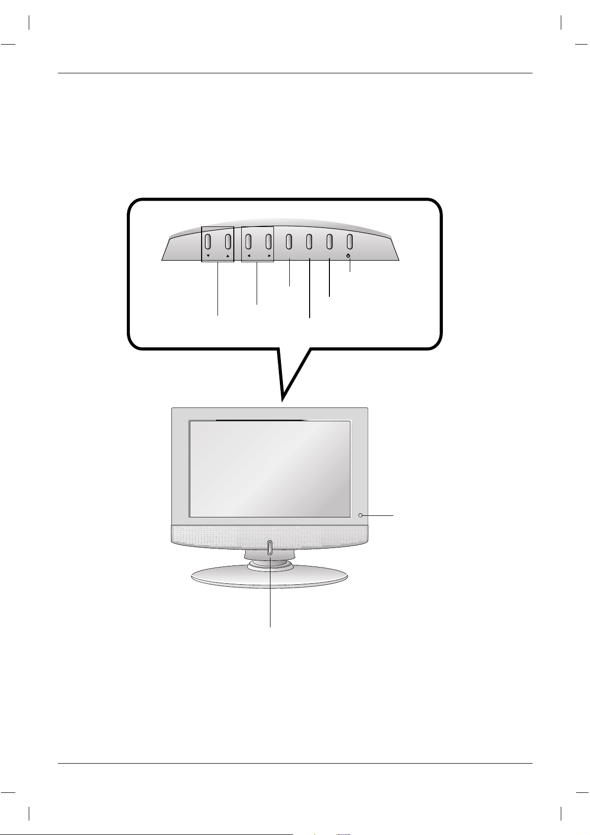
Controls
Controls
Remote Control Sensor
INPUT
MENU
VOL
CH ENTER
/I
Power/Standby Indicator
Glows amber in Standby mode,
Glows blue when the TV is turned on.
Channel
Buttons
Volume
Buttons
Enter
Button
Menu
Button
On/Off
Button
Input
Button
Page 5
Introduction
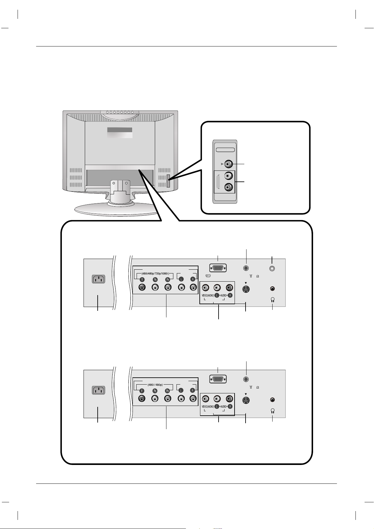
Connection Options
Connection Options
AC INPUT
S-VIDEO
H/P
VIDEO IN*
PC INPUT
PC SOUND
ANT IN ( 75 )
COMPONENT (DTV/DVD IN)
AUDIO
AC INPUT
S-VIDEO
H/P
VIDEO IN
FOR SERVICE
ANT IN ( 75 )
COMPONENT (DTV/DVD IN)
AUDIO
VIDEO IN 2
VIDEO
R
L
AUDIO
15/ 23LC1R
*
20LC1R
*
23LC1R*only
AUDIO INPUT
VIDEO INPUT
COMPONENT (DTV/DVD IN)
((480i/480p/720p/1080i), Audio)
AC INPUT
AUDIO/VIDEO
INPUT
ANTENNA
INPUT
PC SOUND
INPUT
S-VIDEO
INPUT
HEADPHONE
JACK
PC INPUT JACK
COMPONENT (DTV/DVD IN)
((480i/480p), Audio)
AC INPUT
AUDIO/VIDEO
INPUT
ANTENNA INPUT
S-VIDEO
INPUT
HEADPHONE
JACK
FOR SERVICE JACK
*
: VIDEO IN 1 (23LC1R*)
Page 6
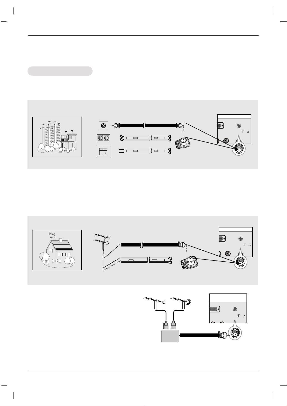
Installation
ANT IN ( 75 )
External Equipment Connections
External Equipment Connections
- For optimum picture quality, adjust antenna direction.
- Typical wall antenna jack used in apartment buildings, connect the antenna cable as shown below.
(Use the correct type of antenna cable for the type of wall antenna jack.)
Wall Connection Jack
Apartment Buildings
Antenna Jack
Copper Wire
Turn clockwise to tighten.
Antenna
Converter
300Ω Flat Wire
75Ω Round Cable
- This type of antenna is commonly used in single family dwellings.
UHF
Antenna
VHF Antenna
- If you have a 75Ω round cable, insert the bronze wire and then tighten the connection nut. If you have
a 300Ω flat wire, connect the twisted wire to the antenna converter and then connect the converter to
the antenna jack on the TV.
- If using 75Ω round cable, do not bend the bronze wire. It may cause poor picture quality.
- In poor signal areas, to get better picture quality, install a signal amplifier to the antenna as
shown to the right.
- If signal needs to be split for two TVs, use an
antenna signal splitter for connection.
Signal
Amplifier
UHF
VHF
Single Family Home
Connecting to an Inside Antenna Setup
Connecting to an Outdoor Antenna Setup
NPUT
ANT IN ( 75 )
Copper Wire
Turn clockwise to tighten.
Antenna
Converter
300Ω Flat Wire
75Ω Round Cable
Antenna Connection
Antenna Connection
Antenna Jack
NPUT
ANT IN ( 75 )
Page 7

Installation
- After setup, be sure to select RGB-PC source on TV.
PC Setup
PC Setup
Connections
1. Set the monitor output resolution on the PC before connecting to the TV.
2. Connect the TV to the PC with the PC cable.
3. Connect the PC audio output to the TV's PC SOUND input.
Viewing Setup
1. Turn on the PC.
2. Use the INPUT button on the remote control to select RGB-PC.
S-VIDEO
H/P
VIDEO IN
PC INPUT
PC SOUND
ANT IN ( 75 )
COMPONENT (DTV/DVD IN)
AUDIO
DTV Setup
DTV Setup
- To watch digitally broadcast programs, purchase and connect a digital set-top box.
Connections
Connect the digital set-top box video outputs to the COMPONENT (Y, P
B, PR) jacks and connect the digital set-top
box audio outputs to the AUDIO jacks. (or, Connect the
set-top box with the D-sub output socket to PC INPUT
socket on the set and audio cable of the set-top box to the
PC SOUND.)
Viewing Setup
1. Turn on the digital set-top box. (Refer to the owner’s
manual for the digital set-top box.)
2. Use the INPUT button on the remote control to select
Component or RGB-DTV.
DTV Receiver
(Set-top Box)
S-VIDEO
H/P
VIDEO IN
PC INPUT
PC SOUND
ANT IN ( 75 )
COMPONENT (DTV/DVD IN)
AUDIO
AUDIOYPBP
R
(L)
(R)
NOTES
a. For optimum picture quality, use standard 1024x768@60Hz (15") / 1360x768@60Hz (23”) computer output at a
60Hz refresh rate . Using other formats (VGA, SVGA, etc.) or refresh rates may result in reduced picture quality. (To
change the computer video output format, please refer to the operating manual for the computer you are using).
b. If the message “
Out of range” appears on the screen, adjust the PC output to a format listed in the
‘Monitor Display Specifications' chart above.
c. The synchronization input form for Horizontal and Vertical frequencies is separate.
DPM (Display Power Management) mode
If the PC goes to power saving mode, the monitor automatically switches to DPM mode.
If you don’t use the PC cable provided, DPM mode may not work.
Monitor Display Specifications
23” only
MODE Resolution
Horizontal
Frequency(kHz)
Vertical
Frequency(Hz)
VGA
SVGA
XGA
WXGA
640x480
800x600
800x600
1024x768
1360x768
31.4
35.1
37.8
48.3
47.6
60
56
60
60
60
DTV Receiver
(Set-top Box)
S-VIDEO
H/P
VIDEO IN
PC INPUT
PC SOUND
ANT IN ( 75 )
COMPONENT (DTV/DVD IN)
AUDIO
AUDIO
RGB-PV OUTPUT
Page 8

Operation
Operation
Operation
Menu Language Selection
Menu Language Selection
TV Operation Overview
TV Operation Overview
- The menus can be shown on the screen in the selected language. First select your language.
1. Press the MENU button and then use
D/E
button to select the SPECIAL menu.
2. Press the
G
button and then use
D/E
button to select Language.
3. Press the
G
button and then use
D/E
button to select your desired language.
From this point on, the on-screen menus will be shown in the language of your choice.
4. Press the ENTER button to save.
1. First, make all equipment connections. Plug the AC Adapter into the TV, then plug the AC Adapter into
a power outlet. At this time, the TV is switched to standby mode.
• In standby mode, press the
POWER, CH (
D,E
), INPUT or number button on the remote control or
ON/OFF, CH (
D,E
), TV button located on the TV to turn the TV on.
2. Select the viewing source by pressing
INPUT.
• Note: See page 18 if you have not auto programmed the TV to receive channels in your local broadcast area.
3. After viewing, press the
POWER button on the remote control or ON/OFF located on the TV. The TV
reverts to standby mode.
NOTE
• If you want to turn the TV off, press the on/off button located on the TV. If you intend to be away on
vacation, disconnect the power plug from the wall power outlet.
Page 9

Operation
Sound Menu Options
Sound Menu Options
1. Use the AUDIO button to select the appropriate sound setup as shown below.
EZEZAudio
Audio
1.
Press the MENU button and then use
D /E
button to select the SOUND menu.
2. Press the
G
button and then use
D /E
button to select EZ Audio.
3. Press the
G
button and then use
D /E
button to select User.
4. Press the
G
button and then use
F /G
button to select the band you want to adjust. Then,
use
D /E
button to adjust the band level.
5. Press the ENTER button to save.
Equalizer
Equalizer
Adjustments
Adjustments
- This function lets you enjoy the best sound without any special adjustment because the TV selects
the appropriate sound option based on the program content.
• You can also adjust
EZ Audio in the SOUND menu.
Flat Music Movie Sports User
- AVL maintains an equal volume level automatically even if the channel is changed.
1.Press the MENU button and then use
D /E
button to select
the SOUND menu.
2. Press the
G
button and then use
D /E
button to select AV L .
3. Press the
G
button and then use
D /E
button to to select
On or Off.
4. Press the ENTER button to save.
AAVLVL(Auto V
(Auto V
olume Leveler)
olume Leveler)
SOUND
EZ Audio
AVL
Balance
Flat
Music
Movie
Sports
User
G
0.1 0.3 1 3 8
Khz
MENU
FG Á
D
E
SOUND
EZ Audio
AVL
Balance
On
Off
MENU
FÁ
D
E
MENU
FG Á
D
E
Page 10

Operation
1. Press the MTS button repeatedly.
Stereo/SAP
Stereo/SAP
Broadcasts Setup
Broadcasts Setup
• Select mono sound mode if the signal is not clear or in poor signal reception areas.
•
Stereo, SAP mode are available only if included on the broadcast signal.
Mono Stereo SAP
- The TV can receive MTS stereo programs and any SAP (Secondary Audio Program) that accompanies
the stereo program, if the broadcaster transmits an additional sound signal as well as the original one.
- Mono: The primary language is heard from left and right speakers. Signal mode is mono.
- Stereo: The primary language is heard from left and right speakers. Signal mode is stereo.
- SAP: The secondary language is heard from left and right speakers.
Sound Menu Options continued
Sound Menu Options continued
1.Press the MENU button and then use
D /E
button to select
the
SOUND menu.
2. Press the
G
button and then use
D /E
button to select
Balance.
3. Press the
G
button and then use
F /G
button to adjust the
sound balance.
• Balance is adjustable from Left 50 to Right 50.
4. Press the ENTER button to save.
Sound Balance
Sound Balance
SOUND
EZ Audio
AVL
Balance
0
MENU
FG Á
D
E
Page 11

Operation
TTimer Menu Options
imer Menu Options
Auto Clock Setup
Auto Clock Setup
- If the time on the clock is incorrect, reset the clock manually.
1. Press the MENU button and then use
D /E
button to select the TIMER menu.
2. Press the
G
button and then use
D /E
button to select Clock.
3. Press the
G
button and then use
D /E
button to select Auto.
4. Press the
G
button and then use
D /E
button to select the time zone for your viewing area. Your
choices are:
Auto, E.S.T. (Eastern Standard Time), C.S.T. (Central Standard Time), M.S.T.
(Mountain Standard Time),
P.S.T. (Pacific Standard Time), Alaska, and Hawaii.
5. Press the
G
button and then use
D /E
button to set PBS channel.
6. Press the
G
button and then use
D /E
button to set D.S.T. (Daylight Savings Time) Auto, Off or
On, depending on whether or not your viewing area observes Daylight Savings Time.
7. Press the ENTER button to save.
- The time is set automatically through from a PBS broadcast signal.
- The PBS channel signal includes information for the correct time and daylight saving time.
Manual Clock Setup
Manual Clock Setup
1. Press the MENU button and then use
D /E
button to select
the
TIMER menu.
2. Press the
G
button and then use
D /E
button to select
Clock.
3. Press the
G
button and then use
D /E
button to select
Manual.
4. Press the
G
button and then use
D /E
button to set the
hour.
5. Press the
G
button and then use
D /E
button to set the
minutes.
6. Press the ENTER button to save.
TIMER
Auto G
Manual
- - : - - - -
Clock
Off timer
On timer
Auto off
TIMER
Auto
Manual
- - : - - - -
Clock
Off timer
On timer
Auto off
Auto clock
Time zone Auto
PBS Ch. TV 1
D.S.T. Auto
MENU
FG Á
D
E
MENU
FG Á
D
E
MENU
FÁ
D
E
Page 12

Operation
- Timer function operates only if current time is set.
- Off-Timer function overrides On-Timer function if they are set to the same time.
- The TV must be in standby mode for the On-Timer to work.
- If you don’t press any button within 2 hours after turning on the TV with the On-Timer function, the TV
will automatically revert to standby mode.
On/Of
On/OfffTT
imer Setup
imer Setup
1. Press the MENU button and then use
D /E
button to select
the
TIMER menu.
2. Press the
G
button and then use
D /E
button to select Off
timer
or On timer.
3. Press the Gbutton and then use
D /E
button to set the hour.
4. Press the
G
button and then use
D /E
button to set the minutes.
5. For
On timer function only:
Press the
G
button and then use
D /E
button to set the chan-
nel at turn-on. Then, press the
G
button and then use
D /E
button to set the turn-on sound level.
6. Press the
G
button and then use
D /E
button to select On or Off.
• Off: Off timer/On timer will not work.
On: Off timer/On timer are active.
7. Press the ENTER button to save.
Sleep
SleepTT
imer Setup
imer Setup
- The Sleep Timer turns the TV off at a preset time.
1. Press the SLEEP button repeatedly to select the number of minutes. First the ‘ --- Min.’ option
appears on the screen, followed by the following sleep timer options: 10, 20, 30, 60, 90, 120, 180, and
240 minutes.
2. When the number of minutes you want is displayed on the screen, press the ENTER button. The timer
begins to count down from the number of minutes selected.
3. To check the remaining minutes before the TV turns off, press the SLEEP button once.
4. To cancel the Sleep Timer, press the SLEEP button repeatedly until ‘ --- Min.’ appears.
Auto of
Auto offf
- If Auto off is active and there is no input signal, the TV switches to Standby mode automatically after
10 minutes.
1. Press the menu button and then use
D /E
button to select
the
TIMER menu.
2. Press the
G
button and then use
D /E
button to select
Auto off.
3. Press the
G
button and then use
D /E
button to select On
or Off.
4. Press the ENTER button to save.
TIMER
Clock
Off timer
On timer
Auto off
On
Off
TTimer Menu Options continued
imer Menu Options continued
TIMER
Clock
Off timer
On timer
Auto off
- - : - - AM
TV 2
Volume 30
On
MENU
FG Á
D
E
MENU
FÁ
D
E
Page 13

Operation
Special Menu Options
Special Menu Options
Closed Captions
Closed Captions
2. An old, bad, or illegally recorded tape is being played.
3. Strong, random signals from a car or airplane interfere with the TV signal.
4. The signal from the antenna is weak.
5. The program wasn’t captioned when it was produced, transmitted, or taped.
Closed captioning is a process which converts the audio portion of a television program into written words
which then appear as subtitles on the television screen. Closed captions allow viewers to read the dia-
Captions are the subtitles of the dialogue and narration of television programs.
For prerecorded programs, program dialogue can be arranged into captions
in advance. Its possible to caption a live program by using a process called
real-time captioning, which creates captions instantly. Real-time captioning is
normally done by professional reporters using a machine shorthand system
and computer for translation into English.
Captioning is an effective system for the hearing-impaired, and it can also aid
in teaching language skills.
• The picture at left shows a typical caption.
• IGNITION:
Picture may flutter, drift, suffer from black spots, or horizontal streaking.
Usually caused by interference from automobile ignition systems, neon lamps,
electrical drills, and other electrical appliances.
• GHOSTS:
Ghosts are caused when the TV signal splits and follows two paths. One is the
direct path and the other is reflected off tall buildings, hills or other objects.
Changing the direction or position of the antenna may improve reception.
• SNOW:
If your receiver is located at the weak, fringe area of a TV signal, your picture
may be marred by small dots. It may be necessary to install a special antenna
to improve the picture.
Caption Tips
FOLLOW ME
Using Closed Captions
• Not all TV broadcasts include closed caption signals.
• Sometimes TV stations broadcast four different caption signals on the same channel. By selecting
From
CC 1 to CC 4
, you can choose which signal you view. CC 1 is usually the signal with the captions, while
Another mode might show demonstration or programming information.
• Your TV might not receive caption signals normally in the following situations.
1. Poor reception conditions are encountered:
Page 14

Operation
Key lock
Key lock
- The TV can be set up so that it can only be used with the remote control.
- This feature can prevent unauthorized viewing.
1. Press the MENU button and then use
D /E
button to select
the
SPECIAL menu.
2. Press the
G
button and then use
D /E
button to select Key
lock
.
3. Press the
G
button and then use
D /E
button to select On
or Off.
4. Press the ENTER button to save.
SPECIAL
Language
Input
Key lock
Power indicator
Caption/Text
Captions
Parental
TV
Video1
Video2
Component
RGB-DTV
RGB-PC
Select Mode
Select Mode
1. Press the MENU button and then
D /E
button to select
the SPECIAL menu.
2. Press the
G
button and then
D /E
button to select Input.
3. Press the
G
button and then
D /E
button to select TV,
Video (
or Video1), Video2, Component, RGB-DTV or
RGB-PC.
• Video (or Video1): VCR connected to the VIDEO IN
socket of the set.
•
Video2: VCR connected to the VIDEO IN 2 socket of the
set. (23LC1R
*
)
•
Component
: DVD connected to the COMPONENT
sockets on the back of set.
• RGB-DTV: SET TOP connected to the PC INPUT and PC
SOUND socket of the set. (15/23LC1R
*
)
•
RGB-PC: PERSONAL COMPUTER connected to the PC
socket of the set. (15/23LC1R
*
)
4. Press the ENTER button to save.
Special Menu Options continued
Special Menu Options continued
- Inputs can be set for TV, Video or RGB-PC mode. Video mode is used when a video cassette recorder
(VCR), or other equipment is connected to the set.
SPECIAL
Language
Input
Key lock
Power indicator
Caption/Text
Captions
Parental
On
Off
Power indicator
Power indicator
- Use this function to set the power indicator on the front side of the product to On or Off. If you set On
at any time, the power indicator will automatically be turned on. Although you select Off, set front light
turns on for a moment when the set turns on.
1. Press the MENU button and then use
D /E
button to select
the
SPECIAL menu.
2. Press the
G
button and then use
D /E
button to select
Power indicator.
3. Press the
G
button and then use
D /E
button to select On
or Off.
4. Press the ENTER button to save.
SPECIAL
Language
Input
Key lock
Power indicator
Caption/Text
Captions
Parental
On
Off
MENU
FÁ
D
E
MENU
FÁ
D
E
MENU
FÁ
D
E
Page 15

Operation
SPECIAL
Language
Input
Key lock
Power indicator
Caption/Text
Captions
Parental
CC1
CC2
CC3
CC4
Text1
Text2
Text3
Text4
Caption/T
Caption/T
ext
ext
1. Press the MENU button and then use
D /E
button to select
the
SPECIAL menu.
2. Press the
G
button and then use
D /E
button to select
Caption/Text.
3. Press the
G
button and then use
D /E
button to select cap-
tion:
CC1, CC2, CC3, CC4, Text1, Text2, Text3, or
Text4.
• CAPTION
The term for the words that scroll across the bottom of the
TV screen; usually the audio portion of the program provided for the hearing impaired.
•
TEXT
The term for the words that appear in a large black frame
and almost cover the entire screen; usually messages
provided by the broadcaster.
4. Press the ENTER button to save.
Captions
Captions
• Use the CC button repeatedly to select Caption.
- Select On from Captions menu in order to adjust the Caption/Text menu.
MENU
FÁ
D
E
SPECIAL
Language
Input
Key lock
Power indicator
Caption/Text
Captions
Parental
On
Off
MENU
FÁ
D
E
1. Press the MENU button and then use
D /E
button to select
the
SPECIAL menu.
2. Press the
G
button and then use
D /E
button to select
Captions.
3. Press the
G
button and then use
D /E
button to select On
or Off.
4. Press the ENTER button to save.
Page 16

Operation
1. Press the MENU button and then use
D /E
button to select the SCREEN menu.
2. Press the
G
button and then use
D /E
button to select desired item.
3. Use the
F /G
button to make appropriate adjustments.
• H-position/V-position
Adjusts picture left/right and up/down.
The adjustment ranges of H-Position is 0~100.
(Based on the input mode, the adjustment range may change.)
• Clock
Minimizes any vertical bars or stripes appearing on the screen background.
The adjustment range is 0~100. (Based on the input mode, the adjustment range may change.)
• Phase
Remove any horizontal noise and clear up or sharpen the character images.
The range adjustment is 0~100. (Based on the input mode, the adjustment range may change.)
• Auto-configure
Automatically adjusts the screen position, clock, and clock phase.
(The displayed image will disappear for a few seconds while Auto-configuration is in progress.)
• Reset
Returns to the default settings programmed at the factory; default settings
cannot be changed.
4. Press the ENTER button to save.
- After setup, be sure to select PC source to see the PC image on TV screen.
Screen Menu Options
Screen Menu Options
SCREEN
To set
ARC *
Auto configure
Manual configure
Reset
MENU
FG Á
D
E
H-Position 85 F
G
D
E
Page 17

Operation
SCREEN
To start
ARC *
Auto configure
Manual configure
Reset
MENU
FG Á
D
E
Picture format (ARC) (23LC1R
Picture format (ARC) (23LC1R
*
*
)
)
1. Press the MENU button and then use
D /E
button to select the SCREEN menu.
2. Press the
G
button and then use
D /E
button to select desired picture format.
3.Press the ENTER button to save.
• Full
When your TV receives the wide screen signal, it will lead you to adjust the picture
horizontally or vertically, in a linear proportion, to fill the entire screen fully. (Not available in all countries)
• 16:9
You can enjoy the cinema (the picture format of 16:9) or general TV programme
through the 16:9 mode.
The screen 16:9 is viewed just like that but the screen 4:3 is
magnified to the left and right so that the screen 16:9 is full.
• 14:9
You can enjoy the picture format of 14:9 or general TV programme through the 14:9
mode.
The screen 14:9 is viewed just like that the screen 4:3 is magnified to the upper / lower
and left / right.
• Zoom
You can enjoy the cinema in a vast screen through the Zoom mode.
The screen 4:3 is magnified to the upper / lower and left / right sides so that the
screen 16:9 is full. The bottom and top of the picture may be lost.
• Spectacle
When your TV receives the wide screen signal, it will lead you to adjust the picture
horizontally, in a nonlinear proportion, to fill the entire screen.
• Original
When your TV receives the wide screen signal, it will be automatically changed to the picture format to be sent.
(Not available in all countries)
• 4:3
This picture format is 4 to 3 of general TV.
NOTES
ARC menu is not available in RGB-PC mode.
Page 18

Maintenance & Product Specifications
Maintenance & Product Specifications
Power Requirement
Power Consumption
Television System
Television Channel
Television Screen
External Antenna Impedance
Audio Output
15LC1R
*
: AC100-240V~ 50/60Hz 0.8A
20LC1R
*
: AC100-240V~ 50/60Hz 1.2A
23LC1R
*
: AC100-240V~ 50/60Hz 1.4A
15LC1R
*
: 40W
20LC1R
*
: 65W
23LC1R
*
: 120W
NTSC
VHF : 2 ~ 13, UHF : 14 ~ 69, Cable : 01 ~ 125
LCD Panel
75 Ω
15LC1R
*
: 3W+3W
20LC1R
*
: 5W+5W
23LC1R
*
: 7W+7W
Product Specifications
Product Specifications
1. Here’s a great way to keep the dust off your screen for a while. Wet a soft cloth in a mixture of
lukewarm water and a little fabric softener or dish washing detergent. Wring the cloth until it’s
almost dry, and then use it to wipe the screen.
2. Make sure the excess water is off the screen, and then let it air-dry before you turn on your TV.
To remove dirt or dust, wipe the cabinet with a soft, dry, lint-free cloth.
Please be sure not to use a wet cloth.
If you leave your TV dormant for a long time (such as a vacation), it’s a good idea to
unplug the power cord to protect against possible damage from lightning or power surges.
- Early malfunctions can be prevented. Careful and regular cleaning can extend the amount of time you
will have your new TV. Be sure to turn the power off and unplug the power cord before you begin any
cleaning.
Cleaning the Screen
Cleaning the Screen
Cleaning the Cabinet
Cleaning the Cabinet
Extended
Extended
Absence
Absence
Maintenance
Maintenance
Page 19

Note
Note
Note
Page 20

 Loading...