

LG 14FU7RB, 14FU7RB-T2 Service Manual
COLOR TV
SERVICE MANUAL
CAUTION
BEFORE SERVICING THE CHASSIS,
READ THE SAFETY PRECAUTIONS IN THIS MANUAL.
CHASSIS : MC059D
MODEL : 14FU7RB
MODEL : 14FU7RB-T2
North/ Latin America http://aic.lgservice.com
Europe/Africa http://eic.lgservice.com
Asia/Oceania http://biz.lgservice.com
Feb., 2010
Printed in ChinaP/NO : MFL40183504
Internal Use Only

- 2 -
CONTENTS
CONTENTS............................................................................................... 2
SAFETY PRECAUTIONS...........................................................................3
SPECIFICATIONS......................................................................................4
ADJUSTMENT ...........................................................................................6
TROUBLE SHOOTING.............................................................................11
BLOCK DIAGRAM...................................................................................15
PRINTED CIRCUIT BOARD ....................................................................16
EXPLODED VIEW....................................................................................18
Copyright©2010 LG Electronics.Inc. All right reserved.
Only for training and service purposes.
LGE Internal Use Only
- 3 -
SAFETY PRECAUTIONS
Many electrical and mechanical parts in this chassis have special safety-related characteristics. These parts are identified by in the
Schematic Diagram and Replacement Parts List.
It is essential that these special safety parts should be replaced with the same components as recommended in this manual to prevent
X-RADIATION, Shock, Fire, or other Hazards.
Do not modify the original design without permission of manufacturer.
General Guidance
An isolation Transformer should always be used during the
servicing of a receiver whose chassis is not isolated from the AC
power line. Use a transformer of adequate power rating as this
protects the technician from accidents resulting in personal injury
from electrical shocks.
It will also protect the receiver and it's components from being
damaged by accidental shorts of the circuitry that may be
inadvertently introduced during the service operation.
If any fuse (or Fusible Resistor) in this TV receiver is blown,
replace it with the specified.
When replacing a high wattage resistor (Oxide Metal Film Resistor,
over 1W), keep the resistor 10mm away from PCB.
Keep wires away from high voltage or high temperature parts.
Due to high vacuum and large surface area of picture tube,
extreme care should be used in handling the Picture Tube. Do
not lift the Picture tube by it's Neck.
X-RAY Radiation
Warning:
To determine the presence of high voltage, use an accurate high
impedance HV meter.
Adjust brightness, color, contrast controls to minimum.
Measure the high voltage.
The meter reading should indicate
23.5 ± 1.5KV: 14-19 inch, 26 ± 1.5KV: 19-21 inch,
29.0 ± 1.5KV: 25-29 inch, 30.0 ± 1.5KV: 32 inch
If the meter indication is out of tolerance, immediate service and
correction is required to prevent the possibility of premature
component failure.
Before returning the receiver to the customer,
always perform an AC leakage current check on the exposed
metallic parts of the cabinet, such as antennas, terminals, etc., to
be sure the set is safe to operate without damage of electrical
shock.
Leakage Current Cold Check(Antenna Cold Check)
With the instrument AC plug removed from AC source, connect an
electrical jumper across the two AC plug prongs. Place the AC
switch in the on position, connect one lead of ohm-meter to the AC
plug prongs tied together and touch other ohm-meter lead in turn to
each exposed metallic parts such as antenna terminals, phone
jacks, etc.
If the exposed metallic part has a return path to the chassis, the
measured resistance should be between 1MΩ and 5.2MΩ.
When the exposed metal has no return path to the chassis the
reading must be infinite.
An other abnormality exists that must be corrected before the
receiver is returned to the customer.
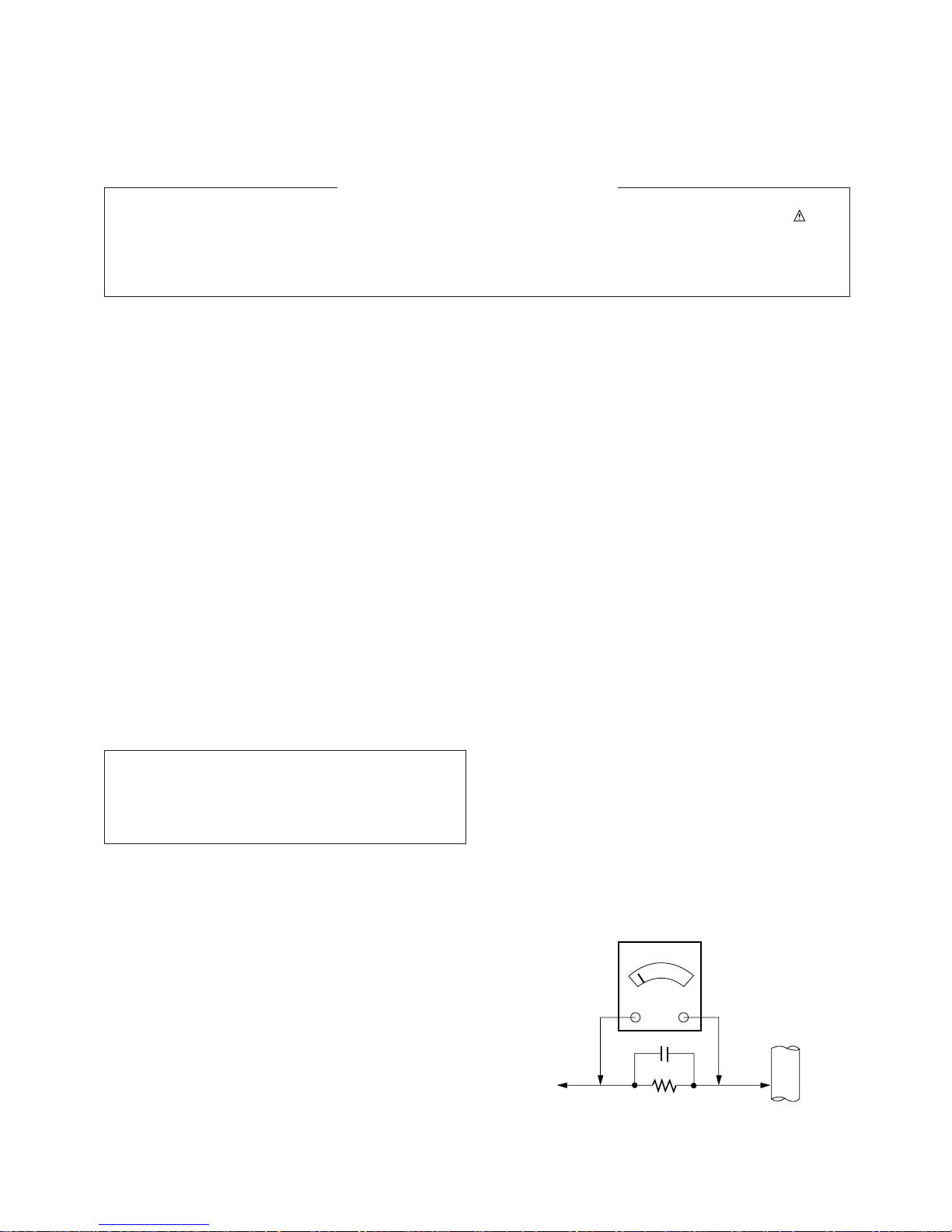
Leakage Current Hot Check (See below Figure)
Plug the AC cord directly into the AC outlet.
Do not use a line Isolation Transformer during this check.
Connect 1.5K/10watt resistor in parallel with a 0.15uF capacitor
between a known good earth ground (Water Pipe, Conduit, etc.)
and the exposed metallic parts.
Measure the AC voltage across the resistor using AC voltmeter
with 1000 ohms/volt or more sensitivity.
Reverse plug the AC cord into the AC outlet and repeat AC voltage
measurements for each exposed metallic part. Any voltage
measured must not exceed 0.75 volt RMS which is corresponds to
0.5mA.
In case any measurement is out of the limits specified, there is
possibility of shock hazard and the set must be checked and
repaired before it is returned to the customer.
Leakage Current Hot Check circuit
The source of X-RAY RADIATION in this TV receiver is the High
Voltage Section and the Picture Tube.
For continued X-RAY RADIATION protection, the replacement
tube must be the same type tube as specified in the
Replacement Parts List.
1.5 Kohm/10W
To Instrument’s
exposed
METALLIC PARTS
Good Earth Ground
such as WATER PIPE,
CONDUIT etc.
AC Volt-meter
IMPORTANT SAFETY NOTICE
0.15uF
Copyright©2010 LG Electronics.Inc. All right reserved.
Only for training and service purposes.
LGE Internal Use Only
- 4 -
General specification
SPECIFICATIONS
Note : Specification and others are subject to change without notice for improvement.
Item
Receiving System
Available Channel
Input Voltage
Market
Screen Size
Aspect Ratio
Display Method
Tuning System
Operating Environment
Storage Environment
Specification
NTSC M (AV 3.58)
NTSC M (AV 3.58)/ PAL M/N
PAL BG, DK, I/NTSC M (AV 3.58/4.43)
SECAM DK
1) VHF : E2 ~ E12
UHF : E21 ~ E69
CATV : S1 ~ S20
HYPER : S21 ~ S41
2) VHF: 02 ~ 13CH (12CH)
UHF : 14 ~ 69CH (56CH)
CATV : 01~125CH (113CH)
AC110 ~ 240V@50/60Hz
AC110 ~ 240V@50/60Hz
Mideast,Africa, Middle South America
Conventional 14
4: 3
CRT
FS
FVS 100 Program
1) Temp : 0 ~ 45 deg
2) Humidity: Below 85 %
1) Temp: -20 ~ 60 deg
2) Humidity: Below 85 %
Remark
Mideast/Africa
L America/Philippines/Taiwan
China/Indonesia/Thai/Vietnam
CIS
PAL MODEL
NTSC MODEL
Mideast/Africa
Middle South America
NTSC MODEL
PAL MODEL
No.
1
2
3
4
5
6
7
8
9
10
Copyright©2010 LG Electronics.Inc. All right reserved.
Only for training and service purposes.
LGE Internal Use Only
Scope
This specification is applied to the MC-059D CHASSIS Colour
TV.
Specification
Each part is tested as below without special appointment.
1) Temperature : 25 ± 5°C (77 ± 9°F), CST : 40 ± 5°C
2) Relative Humidity : 65
± 10%
3) Power Voltage :
4) Specification and performance of each parts are followed
each drawing and specification by part number in
accordance with BOM.
5) Warm up TV set for more than 20min, before the
measurement.
Test Method
1) Capacity: It follows the TV QC Standard of LGE
2) Other standard.
Standard Input Voltage
110 ~ 240V@50/60Hz
110 ~ 240V@50/60Hz
Remark
Market
Mideast/Africa
Middle/South America
Compliance
Safety: As CB standand (IEC60065)
EMC: CE standard (EN55020, EN55013)
Market
Mideast/Africa
Middle/South America
- 5 -
Features and Function
Feature
Key
Station
Picture
Time
Special
Audio Input
Local Key
Remocon
Audio program
Manual program
Program edit
Favorite channel
PSM
CSM
Clock
Off time
On time
Auto Sleep
Language
Input
Child lock
Blue back
Specification
1 Rear (Mono)
6EA/Front: ON/OFF, MENU, Vol (
F, G), PR(E, D)
7EA/Front: ON/OFF, MENU, OK, Vol (
F, G), PR(E, D)
LG Code
System
Storage from
Normal search
Turbo search
Storage
System
Channel
Search
Name
8CH Memory
Dynamic
Standard
Mid
Game
User
Standard
Reddish
Greenish
Bluish
--:--
--:--/On/Off
--:--/Pr/Vol./On/Off
On/Off
English
French
Parsi
Arab
TV/AV
On/Off
On/Off
Remark
Non regulation region
Regulation region
PAL MODEL BG/I/DK
PAL MODEL BG/I/DK
V/UHF or Cable
" or "
Detail drawing Control item:
contrast
Brightness
Colour
Sharpness
Settting now time
Setting shut time
Setting turn on
No signal power off action
English
France
Parsi
Arab
No.
1
2
3
4
5
6
Copyright©2010 LG Electronics.Inc. All right reserved.
Only for training and service purposes.
LGE Internal Use Only
Item
1. Scope of Application
These instructions are applied to MC-059D Chassis.
2. Notes
1) Because this is a cold chassis, it is not necessary to use an
isolation transformer. However, operating it using a
transformer between the power supply line and chassis
input to prevent electric shock and to protect the test
instrument.
2) Adjustment must be done in the correct order.
3) The adjustment must be performed in the circumstance of
25°C±5°C of temperature and 65%±10% of relative
humidity if there is no specific designation.
4) The input voltage of the receiver must keep PAL: 100~240V
±10%,50/60Hz (China/Indonesia/Thailand/Vietnam/CIS
market) in adjusting.
5) The receiver must be operated for about 20 minutes prior to
the adjustment.
6) Signal: Receive the standard color signal. (65dB±1dBuV )
PAL/SECAM: LG standard signal means the digital pattern
PAL-B/G 05CH
7) If not specified, APC ON is APC CLEAR. (DYNAMIC)
3. AGC Voltage Adjustment
3-1. Necessary Instrument
- Digital Multi meter : 1 set
- Max Input Current : Over 1A/ Max Input Voltage : 500Vdc
- Measurement Range : 10mV-100mVdc/ Accuracy : 0.03%
3-2. Adjustment Preparation
1) Input LG standard signal 65dB (±1dB) into 75Ω cable.
2) Connect the digital multi-meter to J105. (AGC Check
Marking)
3-3. Adjustment
1) Select the VP 0(RF AGC) adjustment mode by pressing
IN-START key on the SVC remote control.
2) Press VOL +/-
(F, G) key until the muti-meter shows
reading as below:
3) CAUTION:
Since the signal strength can be easily changed by the
condition of signal cable, you need to check the signal
strength frequently in order to prevent error.
4. Screen Voltage Adjustment
4-1. Adjustment (Use factory Remote Control)
1) Input in the 75Ω cable LG standard signal (Digital
Pattern,480NC)
2) Press the “ADJ’ key of factory remote control once to
make TV set display horizontal line.
3) Turn the Screen Vol. on the FBT clockwise to appear
Horizontal Line and turn it counterclockwise until
horizontal line faintly visible.
(Exit screen voltage adjustment by press " Enter (
A) key of
factory remote control.)
5. Purity and Convergence Adjustment
5-1. Purity Adjustment
(1) Adjustment Preparation
1) Receive Red Raster Pattern for purity adjustment
(51CH).
2) Demagnetize the CPT and Cabinet with a degaussing
coil.
(2) Adjustment
1) Pre-adjust the static convergence (STC) with the 4 and
6-pole magnet.
2) If the horizontal line is inline with CPT Mark, 2-pole
magnet should direct 3-9 o'clock direction.
3) If not, direct 2-pole handle towards 6-12 o'clock direction
and adjust the horizontal line to fall onto the mark
opening the magnet at an angle.
4) Push the DY (deflection yoke) all the way to CPT funnel.
5) Turn the purity magnet (2-pole magnet) so that the
"green" color portion of left side and the blue color
portion on the right side have equal amount of color.
Review <Fig. 1>
6) Pull the DY slowly backward and fix it when the whole
screen becomes red. (The specified torque for fixing DY
screw should be 10Kg/cm). See <Fig. 2>
5-2. Convergency Adjustment
(1) Necessary Instrument
1) Degaussing Coil
2) Convergency fixing instrument (special tools)
(2) Adjustment Preparation
1) Heat run over 30 minutes before adjustment.
2) Demagnetize the CPT and Cabinet by using degaussing
coil.
3) Receive Cross Hatch Pattern for Convergence (09CH).
4) Let the contrast in normal luminance level.
(3) Static Convergence (STC) Adjustment
1) Receive Cross Hatch Pattern for Convergence (09CH).
2) Adjust the focus first seeing to it that the WHITE color
picture quality is sharp enough.
3) Change the angle between the 2 tabs of 4-pole magnet
until vertical Red and Blue lines are unified.
4) Turning the 2 tabs of 4-pole magnet until horizontal Red
and Blue lines are unified. At this time, do not change
the angle between the 2 tabs.
- 6 -
ADJUSTMENT
R
G R B
G R B
G R B
<Fig. 1>
<Fig. 2>
Copyright©2010 LG Electronics.Inc. All right reserved.
Only for training and service purposes.
LGE Internal Use Only
Maker
LG Innote
SANYO
LG Innote
Tuner Spec.
TAEW-G013D
115-B-A86EL
TAEA-G001D
Signal
65dBu
65dBu
65dBu
Remark
PAL
PAL
PAL
AGC Vol.
2.3±0.05V
2.3±0.05V
2.3±0.05V
Tuner P/N
6700MF0014A
6700PF0006B
6700MF0018B
 Loading...