

Page 1

r
User’s Manual
LG Programmable Logic Controlle
MASTER-K 120S series
LG Industrial Systems
- When using LGIS equipment, thoroughly read this datasheet and associated
manuals introduced in this datasheet. Also pay careful attention to safety and
handle the module properly.
- Keep this datasheet within easy reach for quick reference
Page 2

y
y
y
g
SAFETY INSTRUCTIONS
To Prevent injury and property damage, follow these instructions.
Incorrect operation due to ignoring instructions will cause harm or
damage, the seriousness of which is indicated by the following symbols
WARNING
CAUTION
This symbol indicates the possibility of
death or serious injury
This s
mbol indicates the possibility of
injury or damage to property.
■ The meaning of each symbol in this manual and on your equipment is
as follows
This is the safety alert symbol.
Read and follow instructions carefull
situation.
.
to avoid dangerous
.
This s
mbol alerts the user to the presence of “dangerous
voltage” inside the product that mi
ht cause harm or electric
shock.
Page 3

r
r
g
SAFETY INSTRUCTIONS
Design Precautions
Install a safety circuit external to the PLC that keeps the entire system
safe even when there are problems with the external power supply o
the PLC module. Otherwise, serious trouble could result from
erroneous output or erroneous operation.
- Outside the PLC, construct mechanical damage preventing interlock
circuits such as emergency stop, protective circuits, positioning uppe
and lower limits switches and interlocking forward/reverse operation.
When the PLC detects the following problems, it will stop calculation and
turn off all output in the case of watchdog timer error, module interface
error, or other hardware errors.
However, one or more outputs could be turned on when there are
problems that the PLC CPU cannot detect, such as malfunction of output
device (relay, transistor, etc.) itself or I/O controller. Build a fail safe
circuit exterior to the PLC that will make sure the equipment operates
Warnin
safely at such times. Also, build an external monitoring circuit that will
monitor any single outputs that could cause serious trouble.
Make sure all external load connected to output does NOT exceed the
rating of output module.
Overcurrent exceeding the rating of output module could cause fire, damage
or erroneous operation.
Build a circuit that turns on the external power supply when the PLC
main module power is turned on.
If the external power supply is turned on first, it could result in erroneous
output or erroneous operation.
Page 4

SAFETY INSTRUCTIONS
Design Precautions
Do not bunch the control wires or communication cables with the main
circuit or power wires, or install them close to each other. They should
be installed 100mm (3.94inch) or more from each other.
Not doing so could result in noise that would cause erroneous operation.
Caution
Installation Precautions
Caution
Use the PLC in an environment that meets the general specification
contained in this manual or datasheet.
Using the PLC in an environment outside the range of the general
specifications could result in electric shock, fire, erroneous operation, and
damage to or deterioration of the product.
Completely turn off the power supply before loading or unloading the
module.
Not doing so could result in electric shock or damage to the product.
Make sure all modules are loaded correctly and securely.
Not doing so could cause a malfunction, failure or drop.
Make sure I/O and extension connector are installed correctly.
Poor connection could cause an input or output failure.
When install the PLC in environment of much vibration, be sure to
insulate the PLC from direct vibration.
Not doing so could cause electric shock, fire, and erroneous operation.
Be sure to there are no foreign substances such as conductive debris
inside the module.
Conductive debris could cause fires, damage, or erroneous operation.
Page 5

r
r
g
SAFETY INSTRUCTIONS
Wiring Precautions
Completely turn off the external power supply when installing o
placing wiring.
Not doing so could cause electric shock or damage to the product.
Make sure that all terminal covers are correctly attached.
Not attaching the terminal cover could result in electric shock.
Warnin
Caution
Be sure that wiring is done correctly be checking the product’s rated
voltage and the terminal layout.
Incorrect wiring could result in fire, damage, or erroneous operation.
Tighten the terminal screws with the specified torque.
If the terminal screws are loose, it could result in short circuits, fire, o
erroneous operation.
Be sure to ground the FG or LG terminal to the protective ground
conductor.
Not doing so could result in erroneous operation.
Be sure there are no foreign substances such as sawdust or wiring
debris inside the module.
Such debris could cause fire, damage, or erroneous operation.
Page 6

r
r
g
SAFETY INSTRUCTIONS
Startup and Maintenance Precautions
Do not touch the terminals while power is on.
Doing so could cause electric shock or erroneous operation.
Switch all phases of the external power supply off when cleaning the
module or retightening the terminal or module mounting screws.
Not doing so could result in electric shock or erroneous operation.
Do not charge, disassemble, heat, place in fire, short circuit, or solde
the battery.
Mishandling of battery can cause overheating or cracks which could result in
injury and fires.
Do not disassemble or modify the modules.
Doing so could cause trouble, erroneous operation, injury, or fire.
Switch all phases of the external power supply off before mounting o
removing the module.
Not doing so could cause failure or malfunction of the module.
Use a cellular phone or walky-talky more than 30cm (11.81 inch) away
from the PLC
Not doing so can cause a malfunction.
Warnin
Caution
Disposal Precaution
When disposing of this product, treat it as industrial waste.
Not doing so could cause poisonous pollution or explosion.
Caution
Page 7

Revision History
Date Code Revision history
2002.7. 10310000380 First edition is published
2003.5. 10310000380 A revised edition is published
– Main unit and expansion modules are added
– Built-in function are upgraded
2003.9 10310000380 A revised edition is published.
- Main units are added
- Built-in functions are upgraded.
Page 8

◎ Contents ◎
Chapter 1. General
1.1 Guide to Use This Manual ················· 1 - 1
1.2 Features ······················· 1 - 2
1.3 Terminology ······················ 1 - 3
Chapter 2. System Configuration
2.1 Overall Configuration ··················· 2 - 1
2.1.1 Basic System································································································2 - 1
2.1.2 Cnet I/F System·····························································································2 - 2
2.2 Product Functional Model ················· 2 - 4
2.2.1 Product Functional Block················································································· 2 - 4
2.2.2 MASTER-K120S Series System Equipment Product ·············································2 - 5
Chapter 3. General Specifications
3.1 General Specifications ·················· 3 - 1
Chapter 4. Names of Parts
4.1 Main Unit ······················· 4 - 1
4.1.1 60 Points Main Unit (Standard)·········································································4 - 2
4.1.2 40 Points Main Unit (Standard)··········································································4 -3
4.1.3 30 Points Main Unit (Standard)·········································································4 - 4
4.1.4 20 Points Main Unit (Standard)·········································································4 - 5
4.1.5 30 Points Main Unit (Economic)········································································4 - 6
4.1.6 20 Points Main Unit (Economic)·········································································4 -7
4.1.7 14 Points Main Unit (Economic)········································································ 4 - 7
4.1.8 10 Points Main Unit (Economic)········································································ 4 - 7
4.2 Expansion I/O Module··················· 4 - 8
4.2.1 20 Point I/O Module························································································4 - 8
4.2.2 10 Point I/O Module························································································4 - 8
4.2.3 8 Point I/O Module························································································· 4 - 9
4.3 Special Module ···················· 4 - 10
4.3.1 A/D·D/A Combination Module········································································4 - 10
4.3.2 D/A Conversion Module··················································································4 - 11
4.3.3 A/D Conversion Module··················································································4 - 11
4.3.4 Analog Timer Module·····················································································4 - 12
4.3.5 RTD Input Module·························································································4 - 12
Page 9

4.4 Communication I/F Module ················· 4 - 13
4.4.1 Cnet I/F Module····························································································4 - 13
4.4.2 Fnet I/F Module····························································································4 - 13
4.4.3 Pnet I/F Module····························································································4 - 14
4.4.4 DeviceNet I/F Module···················································································· 4 - 14
4.5 Option Module ····················· 4 - 14
Chapter 5. Power Supply / CPU
5.1 Power Supply Specifications ················ 5 - 1
5.1.1 Standard Type·······························································································5 - 1
5.3.2 Economic Type······························································································5 - 1
5.2 CPU Specifications···················· 5 - 2
5.2.1 Standard Type·······························································································5 - 2
5.2.2 Economic Type······························································································5 - 4
5.3 Operation Processing ··················· 5 -6
5.3.1 Operation Processing Method···········································································5 - 6
5.3.2 Operation Processing at Momentary Power Failure Occurrence······························· 5 - 7
5.3.3 Scan Time···································································································· 5 - 8
5.3.4 Scan Watchdog Timer·····················································································5 - 8
5.3.5 Timer Processing ·························································································5 - 9
5.3.6 Counter Processing·······················································································5 - 12
5.4 Program························································································5 - 14
5.4.1Classifications of Program ·············································································5 - 14
5.4.2 Program Execution Procedure·········································································5 - 14
5.4.3 Interrupt Programs························································································5 - 15
5.4.4 Error Handling······························································································5 - 17
5.5 Operation Modes ···················· 5 - 19
5.5.1 RUN Mode··································································································5 - 19
5.5.2 STOP Mode·································································································5 - 20
5.5.3 PAUSE Mode·······························································································5 - 20
5.5.4 DEBUG Mode(Standard Type Only)··································································5 - 20
5.5.5 Operation Mode Change················································································5 - 21
5.6 Function························ 5 - 23
5.6.1 Self-diagnosis······························································································5 - 23
5.6.2 I/O Force On/Off function ··············································································5 - 24
5.6.3 Direct I/O Operation function···········································································5 - 27
5.6.4 System error history······················································································5 - 27
5.7 Memory Configuration··················· 5 - 28
5.8 I/O Address Allocation··················· 5 - 29
5.9 Built-in Cnet Selection switch ···························································5 - 30
5.9.1 Structure·····································································································5 - 30
Page 10

5.9.2 Usage········································································································5 - 30
5.10 External Memory Module ················· 5 - 32
5.10.1 Structure···································································································5 - 32
5.10.2 Usage·······································································································5 - 32
5.11 RTC Module······················ 5 - 34
5.11.1 Structure···································································································5 - 34
5.11.2 Usage······································································································5 – 34
Chapter 6. Input and Output Modules
6.1 Input / Output Specifications ················ 6 - 1
6.2 Digital Input Specifications ················· 6 - 2
6.2.1 Main Unit ·····································································································6 - 2
6.2.2 Expansion Module ·························································································6 - 5
6.3 Digital Output Specification ················· 6 - 6
6.3.1 Main Unit (Relay Output)·················································································6 - 6
6.3.2 Main Unit (Tr Output :DRT/DT Type Only) ···························································6 - 9
6.3.3 Expansion Module ························································································ 6 - 11
Chapter 7. Usage of Various Functions
7.1 Built-in Functions ···················· 7 - 1
7.1.1 High Speed Counter Function··········································································· 7 - 1
7.1.2 Pulse Catch Function·····················································································7 - 14
7.1.3 Input Filter Function·······················································································7 - 16
7.1.4 External Interrupt Function··············································································7 - 17
7.1.5 PID Control Function(Standard Type Only)·························································7 - 19
7.2 Special Module ····················· 7 - 39
7.2.1 A/D·D/A Combination Module········································································7 - 40
7.2.2 A/D Conversion Module··················································································7 - 49
7.2.3 D/A Conversion Module··················································································7 - 55
7.2.4 Analogue Timer ··························································································7 - 61
7.2.5 RTD input Module ·······················································································7 - 63
7.3 Positioning Function(DRT /DTtype only) ············ 7 - 69
7.3.1 Specification································································································7 - 69
7.3.2 Positioning Function······················································································7 - 72
7.3.3 Positioning parameter and Operation Data·························································7 - 85
7.3.4 Instructions ································································································7 - 91
7.3.5 Flag list and Error code ··············································································7 - 100
7.3.6 Wiring with servo and stepping motor driver······················································7 - 104
Page 11

Chapter 8. Communication Function
8.1 Dedicated Protocol Communication ·············· 8 - 1
8.1.1 Introduction ··································································································8 - 1
8.1.2 System configuration method ···········································································8 - 2
8.1.3 Frame Structure ····························································································8 - 5
8.1.4 Lists of Commands ························································································8 - 7
8.1.5 Data Type····································································································8 - 8
8.1.6 Execution of Commands ·················································································8 - 9
8.1.7 1:1, 1:n Built-in Communication between MASTER-K120S’s ································8 - 28
8.1.8 Error Codes·································································································8 - 38
8.2 User Defined Protocol Communication ············· 8 - 39
8.2.1 Introduction ·································································································8 - 39
8.2.2 Parameter Setting·························································································8 - 39
8.2.3 Instruction ·································································································8 - 47
8.2.4 Example of usage ·······················································································8 - 48
8.3 Modbus Protocol Communication··············· 8 - 57
8.3.1 Introduction ·································································································8 - 57
8.3.2 Basic Specifications ······················································································8 - 57
8.3.3 Parameter Setting·························································································8 - 60
8.3.4 Instruction and examples ··············································································8 - 62
8.4 No Protocol Communication ················ 8 - 67
8.4.1 Introduction ·································································································8 - 67
8.4.2 Parameter Setting·························································································8 - 68
8.4.3 Instructions··································································································8 - 69
8.4.4 Examples ··································································································8 - 71
8.5 Remote Connection and Communication I/F module ········ 8 - 73
8.5.1 Remote Connection·······················································································8 - 73
8.5.2 Communication I/F Module ·············································································8 - 76
Chapter 9. Installation and Wiring
9.1 Installation ······················· 9 - 1
9.1.1 Installation Environment·················································································· 9 - 1
9.1.2 Handling Instructions······················································································9 - 3
9.1.3 Connection of Expansion Module······································································9 - 6
9.2 Wiring ························ 9 - 7
9.2.1 Power Supply Wiring······················································································ 9 - 7
9.2.2 Input and Output Devices Wiring·······································································9 - 8
9.2.3 Grounding···································································································· 9 - 9
9.2.4 Cable Specifications for wiring··········································································9 - 9
Page 12

Chapter 10. Maintenance
10.1 Maintenance and Inspection ················ 10 - 1
10.2 Daily Inspection ···················· 10 - 1
10.3 Periodic Inspection ··················· 10 - 2
Chapter 11. Troubleshooting
11.1 Basic Procedure of Troubleshooting ············· 11 - 1
1 1.2 Troubleshooting ············································································ 11 - 1
11.2.1 Troubleshooting flowchart used when the power LED turns off ·····························11 - 2
11.2.2 Troubleshooting flowchart used when the error LED is flickering····························11 - 3
11.2.3 Troubleshooting flowchart used when the RUN LED turns off································11 - 4
11.2.4 Troubleshooting flowchart used when the I/O devices doesn’t operate normally ········11 - 5
11.2.5 Troubleshooting flowchart used when a program can’t be written to the CPU············11 - 7
1 1.3 Troubleshooting Questionnaire························································· 11 - 8
1 1.4 Troubleshooting Examples······························································· 11 - 9
11.4.1 Input circuit troubles and corrective actions·······················································11 - 9
11.4.2 Output circuit troubles and corrective actions···················································11 - 10
11.5 Error code list ··············································································11 - 12
Appendix··················································································································
Appendix 1 System Definitions·······························································App1-1
Appendix 2 Flag Lists···········································································
App2-1
Appendix 3 Dimensions········································································App3-1
Page 13

Chapter 1 General
Chapter 1. General
1.1 Guide to Use This Manual
This manual includes specifications, functions and handling instructions for the MASTER-K120S series PLC.
This manual is divided up into chapters as follows:
No. Title Contents
Chapter 1 General Describes configuration of this manual, unit's features and terminology.
Chapter 2 System configuration Describes available units and system configurations in the MASTER-K120S series.
Chapter 3 General Specification Describes general specifications of units used in the MASTER-K120S series.
Chapter 4 Names of Parts Describes each kind of manufacturing goods, titles, and main functions
Chapter 5 Power Supply / CPU
Chapter 6 Input and Output
Chapter 7
Chapter 8 Communication Function Describes built-in communication functions
Chapter 9 Installation and Wiring Describes installation, wiring and handling instructions for reliability of the PLC system
Chapter 10 Maintenance
Chapter 11 Troubleshooting Describes various operation errors and corrective actions.
Appendix 1 System Definitions Describes parameter setting for basic I/O and communications module
Appendix 2 Flag List Describes the types and contents of various flags.
Appendix 3 Dimensions Shows dimensions of the main units and expansion modules
REMARK
Usage of Various
Functions
Describes each kind of manufactured goods' usage
Describes the check items and method for long-term normal operation of the PLC
system.
-. This manual does not describes the programming method. For their own functions, refer to the related user's
manuals.
1-1
Page 14

Chapter 1 General
1.2. Features
1) MASTER-K120S series is extremely compact, to fit a wide range of applications and have following features.
(1) High speed processing
High speed processing of 0.1~0.9µs/step with an general purpose processor included .
(2) Various built-in functions
The main unit can perform many functions without using separate modules. Therefore, It is possible to construct various
systems just using the main unit.
• Fast Processing Applications
- Pulse catch: Allows the main unit to read a pulse which has width as small as 10 ㎲.
- High speed counter(Economic): Support high-speed counting up to 100(10)kHz for 1 phase, 50(5)kHz for 2 phase.
- External interrupts : Using in applications that have a high-priority event which requires immediate responses.
• The input filter function help reduce the possibility of false input conditions from external noise, such as signal
chattering. The filter time can be programmed from 0 to 1000ms.
• Using RS-232C and RS-485 built-in port, MASTER-K120S can connects with external devices, such as personal
computers or monitoring devices and communicate 1:N with MASTER-K120S system.
• Using built-in PID control function, PID control system can be constructed without using separate PID module.
• Using built-in Positioning function, position control system can be constructed without using separate position control
module.(only DRT/DT type has built-in positioning function)
(3) Battery-less
The user’s program can be saved permanently, because it is stored to EEPROM.
(4) When program is edited during processing, it is stored to EEPROM automatically
(5) Open network by use of communication protocols in compliance with international standard specifications.
(6) Various special modules that enlarge the range of application of the PLC
(7) It can easily do On/Off of the system, using RUN/STOP switch.
(8) It can easily save the user program in EEPROM by simple manipulation in KGLWIN without using external memory.
(9) Strong self-diagnostic functions
It can detect the cause of errors with more detailed error codes.
(10) It can prevent unintentional reading and writing, using password.
(11)
Debugging function(Standard type)
On-line debugging is available when the PLC Operation mode is set to debug mode.
y executed by one command.
y executed by break-point settings.
y executed by the condition of the device
y executed by the specified scan time.
(12) Various program execution function
External and internal interrupt program as well as scan program can be executed by setting the execution condition.
Therefore, user can set variously program execution mode.
1-2
Page 15

Chapter 1 General
1.3 Terminology
The following table gives definition of terms used in this manual.
Terms Definition Remarks
A standard element that has a specified function which configures the
Module
Unit
PLC system
KGLWIN
KLD-150S
I/O Image Area Internal memory area of the CPU module which used to hold I/O statuses.
Watch Dog Timer
system. Devices such as I/O board, which inserted onto the mother board
or base unit.
A single module or group of modules that perform an independent
Operation as a part of PLC system.
A system which consists of the PLC and peripheral devices. A user program
can control the system.
A program and debugging tool for the MASTER-K series. It executes
program creation, edit, compile and debugging(A computer software).
A hand-held loader used for program creation, edit, compile and debugging
for MASTER-K series.
Supervisors the pre-set execution times of programs and warns if a
program is not completed within the pre-set time.
Example)
CPU module
Power Supply module
I/O module
Example)
Main unit
FAM
Fnet Fieldbus network
Cnet Computer network(RS-232C, RS-422/485)
RTC
Abbreviation of the word ‘Factory Automation Monitoring S/W’. It is used to
call S/W packages for process supervision.
Abbreviation of ‘Real Time Clock’. It is used to call general IC that
contains clock function.
1-3
Page 16

Chapter 1 General
Terms Definition Remarks
Sink Input
Source
Input
Current flows from the switch to the PLC input terminal if a input signal turns on.
Current flows from the PLC input terminal to the switch after a input signal turns
on.
Current flows from the load to the output terminal and the PLC output turn on.
Sink Output
Source
Output
Output
Contact
Current flows from the output terminal to the load and the PLC output turn on.
Output Contact
1-4
Page 17
Chapter 2 System Configuration
Chapter 2. System Configuration
The MASTER-K120S series has suitable to configuration of the basic, computer link and network systems.
This chapter describes the configuration and features of each system.
2.1 Overall Configuration
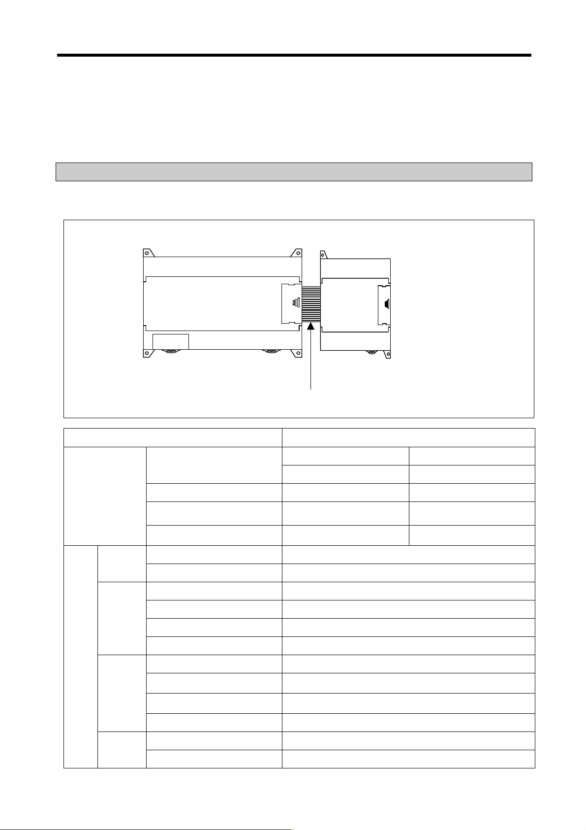
2.1.1 Basic system
Main unit
expansion
cable
expansion
module
Total I/O points
Maximum number
of expansion
modules
Main unit
Expansion
module
Items
Communic
ation I/F
module
Digital I/O module
A/D-D/A module
Analog timer
Cnet I/F module
Economic
Standard
Digital I/O module
Analog I/O module
Analog timer
Resistance Temperature Detactor
Cnet I/F modules
DeviceNet I/F module
FieldBus I/F module
Profibus I/F Module
• 10-120 points
Standard Economic
• 3 modules • 2 modules
• 3 modules • 2 modules
• 3 modules • 2 modules
• 1 module • 1 modules
• K7M-DR10/14/20/30UE
• K7M-DR//DRT/DT20/30/40/60U
•
G7E-DR10A, G7E-DR20A, G7E-TR10A, G7E-DC08A, G7E-RY08A
• G7F-ADHA, G7F-ADHB, G7F-AD2A, G7F-DA2I, G7F-DA2V
• G7F-AT2A
• G7F-RD2A
• G7L-CUEB, G7L-CUEC
• G7L-DBEA
• G7L-FUEA
• G7L-PBEA
Option
module
RTC
Memory
• G7E-RTCA
• G7M-M256B
2-1
Page 18
Chapter 2 System Configuration
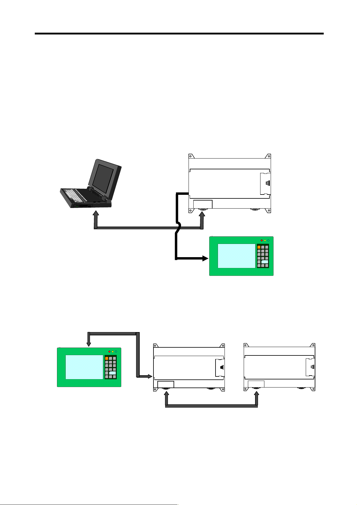
2.1.2 Cnet I/F system
Cnet I/F System is used for communication between the main unit and external devices using RS-232C/RS-422 Interface.
The MK120S has a built-in RS-232C port, RS-485 port and has also G7L-CUEB for RS-232C, G7L-CUEC for RS-422. It is
possible to construct communication systems on demand.
1) 1:1 Communications system
(1) 1:1 ratio of an external device (computer) to main unit using a built-in port
MASTER-K120S
RS-232C
Monitoring Device
RS-485
(2) 1:1 ratio of an external device (monitoring unit) to main unit using a built-in RS-485 port
RS-485
MASTER-K120S
MASTER-K120S
Monitoring Device
RS-232C
2-2
Page 19
Chapter 2 System Configuration
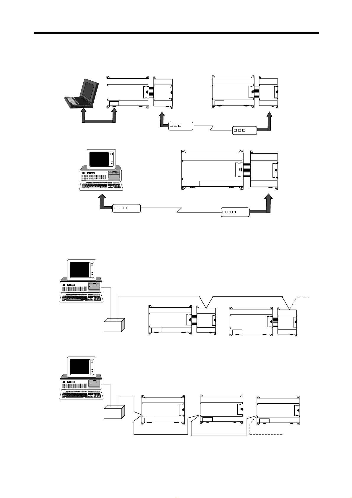
(3) RS-232C Communication over a long distance via modem by Cnet I/F modules
MASTER-K120S
Modem
2) 1:n Communications system
G7L-CUEB
Modem
MASTER-K120S
MASTER-K120S
G7L-CUEB
Modem
G7L-CUEB
Modem
This method can connect between one computer and multiple main units for up to 32 stations
RS-232C ⇔ RS-422 Converter
MASTER-K120S
G7L-CUEC
MASTER-K120S
G7L-CUEC
MASTER-K120S
RS-232C ⇔ RS-485
Converter
Built-in RS-485 Built-in RS-485
* Refer to ‘chapter 8. communication function’ for details.
2-3
Built-in RS-485
Page 20
Chapter 2 System Configuration
2.2 Product Functional Model
The following describes functional model of the MASTER-K120Sseries.
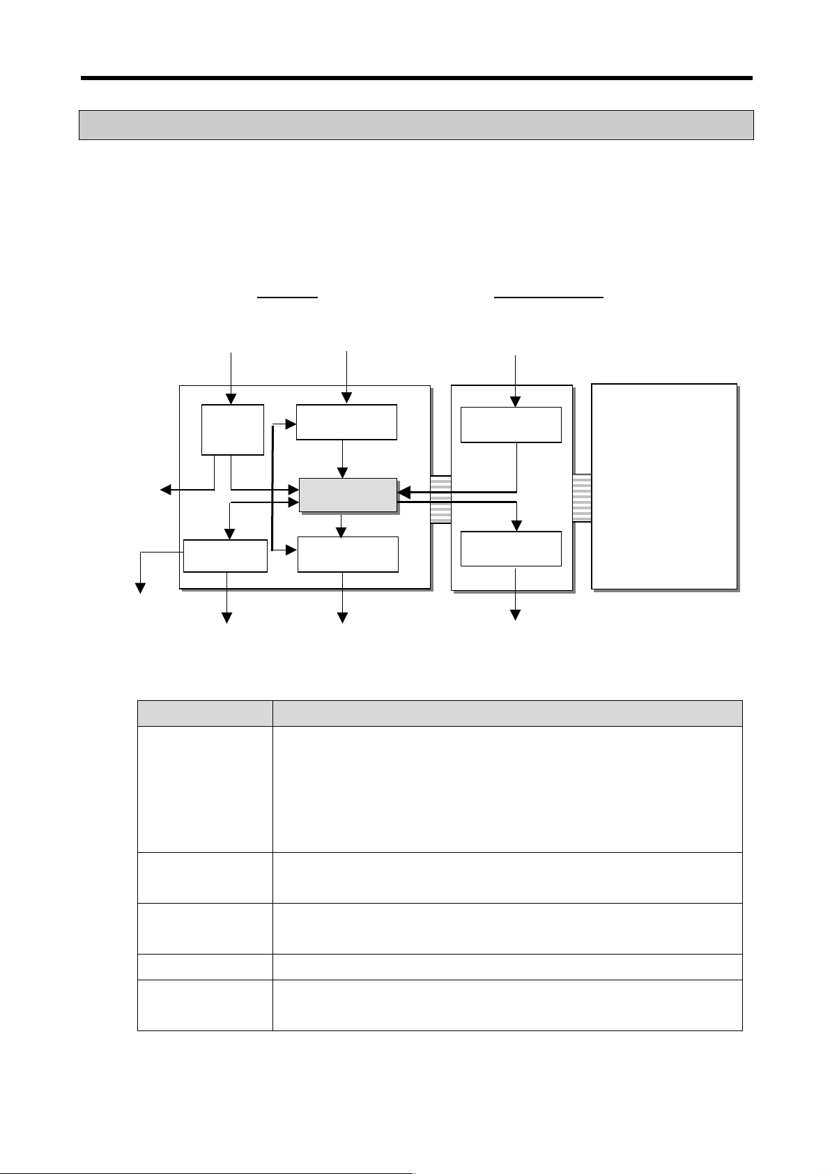
2.2.1 Product Functional Block
Product function block for the K120S series is as follows.
Power supply Input signal Input signal
DC24V
Power
supply
Built-in
RS-485
Built-in RS-232C I/F Output signal Output signal
Power
supply
Comm. I/F
Main Unit Expansion Modules
•
Input
CPU
Output
Input
Output
Special/communication
modules
Sub-system Description
CPU
Input
Output
Power Supply
Communication
Interface
• Signal processing function
-. Operating system function
-. Application program storage / memory function
-. Data storage / memory function
-. Application program execution function
• The input signals obtained from the machine/process to appropriate signal levels for
processing
• The output signals obtained from the signal processing function to appropriate signal
levels to drive actuators and/or displays
• Provides for conversion and isolation of the PLC system power from the main supply
• Provides the data exchange with other systems or PADT, such as KGLWIN, personal
computers
2-4
Page 21

Chapter 2 System Configuration
2.2.2 K120S Series System Equipment Product
1) Main Unit – Standard type
Items Models
K7M-DR20U
K7M-DR30U
K7M-DR40U
K7M-DR60U
K7M-
Main Unit
DRT/DT20U
K7M-
DRT/DT30U
K7M-
DRT/DT40U
K7M-
DRT/DT60U
2) Main Unit – Economic type
Items Models
K7M-DR10UE
K7M-DR14UE
Main Unit
K7M-DR20UE
K7M-DR30UE
I/O Point &
Power Supply
12 DC inputs(24VDC)
8 relay outputs
85~264 VAC
18 DC inputs(24VDC)
12 relay outputs
85~264 VAC
24 DC inputs(24VDC)
16 relay outputs
85~264 VAC
36 DC inputs(24VDC)
24 relay outputs
85~264 VAC
12 DC inputs(24VDC)
4/0 relay outputs
4/8 TR outputs
85~264 VAC
18 DC inputs(24VDC)
8/0 relay outputs
4/12 TR outputs
85~264 VAC
24 DC inputs(24VDC)
12/0 relay outputs
4/16 TR outputs
85~264 VAC
36 DC inputs(24VDC)
20/0 relay outputs
4/24 TR outputs
85~264 VAC
I/O Point &
Power Supply
6 DC inputs(24VDC)
4 relay outputs
85~264 VAC
8 DC inputs(24VDC)
6 relay outputs
85~264 VAC
12 DC inputs(24VDC)
8 relay outputs
85~264 VAC
18 DC inputs(24VDC)
12 relay outputs
85~264 VAC
Built-in Function Remark
• Program capacity : 10 k steps
• Max. expansion : 3 modules
• High-speed counter :
- 1 Phase : 100 kHz 1channel, 20 kHz 2channel.
- 2 Phase : 50 kHz 1channel, 10 kHz 1channel.
• Pulse catch : pulse width 10 ㎲ 2 points, 50 ㎲ 6 points,
• External interrupt: : 10 ㎲ 2 points, 50 ㎲ 6 points
• Input filter: 0 ~ 1000ms (can be designated with groups)
• PID control function
• RS-232C communication, RS-485 communication
• Program capacity : 10 k steps
• Max. expansion : 3 modules
• High-speed counter :
- 1 Phase : 100 kHz 1channel, 20 kHz 2channel.
- 2 Phase : 50 kHz 1channel, 10 kHz 1channel.
• Pulse catch : pulse width 10 ㎲- 2 points, 50 ㎲- 6 points,
• External interrupt: : 10 ㎲- 2 points, 50 ㎲- 6 points
• Input filter: 0 ~ 1000ms (can be designated with groups)
• PID control function
• RS-232C communication, RS-485 communication
• Positioning function
- 2axes 100 kpps
- Absolute / Incremental positioning method
- Single / Repeat operation method
- End / Keep / Continuous mode
- Return to origin, JOG, PWM, velocity control
Built-in Function Remark
• Program capacity : 2 k steps
• Max. expansion : 2 modules
• Pulse catch : pulse width 50 ㎲ 4 points,
• High-speed counter :
- 1 Phase : 10 kHz 2channel.
- 2 Phase : 5 kHz 1channel.
• External interrupt: : 50 ㎲ 4 points
• Input filter: 0 ~ 1000ms (can be designated with groups)
• RS-232C communication
• RS-485 communication(K7M-DR10/14UE only)
• Built-in analog timer(K7M-DR10/14UE only)
2-5
Page 22

Chapter 2 System Configuration
3) Expansion Modules
Section Items Models Description Remark
Expansion
module
Special
module
G7E-DR10A
G7E-DR20A
G7E-DC08A
Digital I/O module
G7E-TR10A
G7E-RY08A
G7E-DR08A
A/D-D/A
Combination module
A/D conversion module G7F-AD2A
D/A conversion module
Analog timermodule G7F-AT2A
RTD module G7F-RD2A
G7F-ADHA
G7F-ADHB
G7F-DA2I
G7F-DA2V
G7L-CUEB
• 6 DC inputs / 4 relay outputs
• 12 DC inputs / 8 relay outputs
• 8 DC inputs
• 10 Transistor outputs
• 8 relay outputs
• 4 DC Input, 4 Relay output
• A/D : 2 channel , D/A : 1 channel
• A/D : 2 channel , D/A : 2 channel
• A/D : 4 channel
• D/A : 4 channel(current output)
• D/A : 4 channel(voltage output)
• Points : 4points
• Digital output range : 0~200
• Resistance temperature detactor
- 4 channel(Pt100, JPt100)
• RS-232C : 1 channel
Slim Type
Slim Type
Slim
Type
Slim
Type
Slim
Type
Standard
type only
G7L-CUEC
Communication I/F module
RTC module G7E-RTCA
External Memory G7M-M256B
* External memory G7M-M256 isn’t supported in K120S series. Only G7M-M256B is available for K120S series.
G7L-DBEA
G7L-FUEA
G7L-PBEA
• RS-422 : 1 channel
• DeviceNet I/F module (Slave)
• FieldBus I/F module
• Profibus I/F module (Slave)
• Real Time Clock module
• External Memory module
2-6
Standard
type only
Page 23
Chapter 3 General Specifications
p
Chapter 3. General Specifications
3.1 General Specifications
The following table shows the general specifications of the MASTER-K120S series.
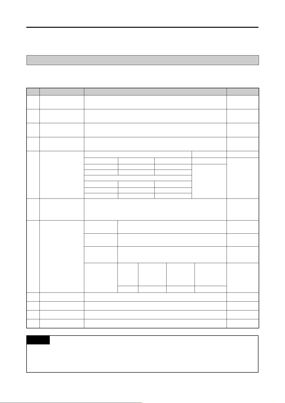
No. Item Specifications References
1
2
3
4
5 Vibrations
6 Shocks
Operating ambient
Temperature
Storage ambient
Temperature
Operating ambient
Humidity
Storage ambient
Humidity
0 ~ 55 °C
−25 ~ +70 °C
5 ~ 95%RH, non-condensing
5 ~ 95%RH, non-condensing
Occasional vibration -
Frequency Acceleration Amplitude Sweep count
10 ≤ f < 57Hz
57 ≤ f ≤ 150Hz
Frequency Acceleration Amplitude
10 ≤ f < 57Hz
57 ≤ f ≤ 150Hz
• Maximum shock acceleration: 147 m/s
• Duration time: 11ms
• Pulse wave: half sine pulse ( 3 shocks per axis, on X, Y, Z axis )
−
2
{1G}
9.8m/s
Continuous vibration
−
2
{0.5G}
4.9m/s
2
{15G}
0.075mm
−
10 times for each
X, Y, Z axis
0.035mm
−
IEC 61131-2
IEC 61131-2
7 Noise Immunity
8
9
10
11
Atmosphere Free of corrosive gases and excessive dust
Altitude
Pollution degree
Cooling method
Square wave
Impulse noise
Electronic
discharge
Radiated
electromagnetic
field noise
Fast transient &
burst noise
Up to 2,000m
2
Air-cooling
± 1,500 V
Voltage: 4 kV ( Discharge by contact )
27 ~ 500 MHz, 10 V/m
Item Power supply
Voltage
2kV 1kV 0.25kV
Digital I/O
(24V and up)
Digital I/O
(less than24V)
Analog I/O
Interface
LGIS’ Internal
Standard
IEC 61131-2,
IEC 1000-4-2
IEC 61131-2,
IEC 1000-4-3
IEC 61131-2
IEC 1000-4-4
REMARK
1)
IEC (International Electrotechnical Commission): A n international civi lian institute who establishes internatio nal standards i n area of elec tric
and electronics.
2) Pollution degree: An indicator, which indicates pollution degree, which determine insulation performance of equipment.
* Pollution degree 2 : Normally, only non-conductive pollution occurs. Occasionally, however, a temporary conductivity caused by
condensation shall be ex
ected.
3-1
Page 24
Chapter 4 Names of Parts
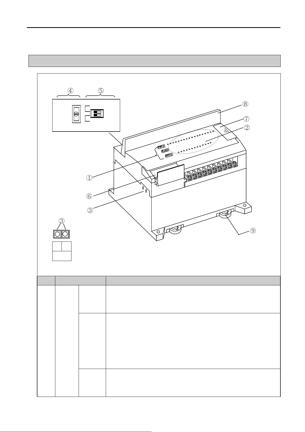
Chapter 4. Names of Parts
4.1 Main Unit
③
④
⑤
①
⑥
③
⑧
⑦
②
⑨
- +
RS-485
No. Name Description
Indicates status of power supply to the system
CPU
Condition
LED
PWR LED
RUN LED
ERR LED
y On : When the supplied power is normal
y Off : When the supplied power is abnormal
Indicates operating status of main unit
y On : Indicates local key switch or remote running mode
y Off : with the followings, LED turns off
- When the supplied power to the main unit is abnormal.
- While key switch is on stop mode
- Detecting an error which makes operation stop
Indicates operating status of CPU
y Flickering : self-inspected error
y Off: CPU is working normal.
4 -1
Page 25
Chapter 4 Names of Parts
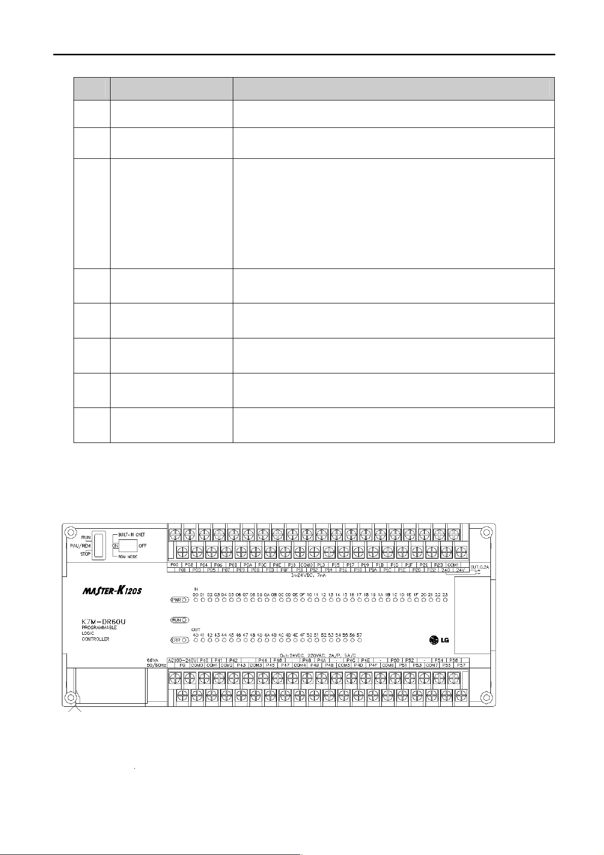
No Name Description
I/O LED Indicates operating status of I/O
Built-in RS-485 connector
(Except K7M-DR10/14UE)
2-pin connector for built-in RS-485 communications.
Designates main unit’s operation mode
y RUN : Run program operation
Key switch for mode creation
.(Except economic type)
Dip-switch for Cnet I/F
RS-232C connector
Expansion connector cover Connector cover to connect with expansion unit
Terminal block cover
Private hook DIN rail
4.1.1 60-points main unit (Standard)
1) K7M-DR60U
y STO P : Stop program operation
y P AU / REM: usage of each modules are as follows:
- P A U S E : temporary stopping program operation
- REMOTE : designates remote driving
See Chapter 5.
9-pin DIN connector to connect with external devices like KGLWIN
Protection cover for wiring of terminal block
Private part hook for DIN rail
4 -2
Page 26
Chapter 4 Names of Parts
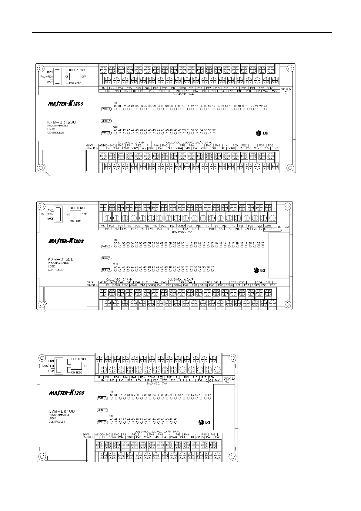
2) K7M-DRT60U
3) K7M-DT60U
4.1.2 40-points main unit (Standard)
1) K7M-DR40U
4 -3
Page 27
Chapter 4 Names of Parts
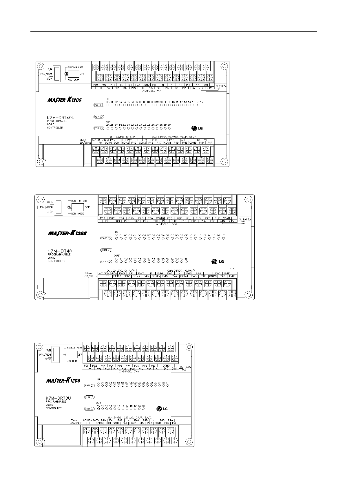
2) K7M-DRT40U
3) K7M-DT40U
4.1.3 30-points main unit (Standard)
1) K7M-DR30U
4 -4
Page 28
Chapter 4 Names of Parts
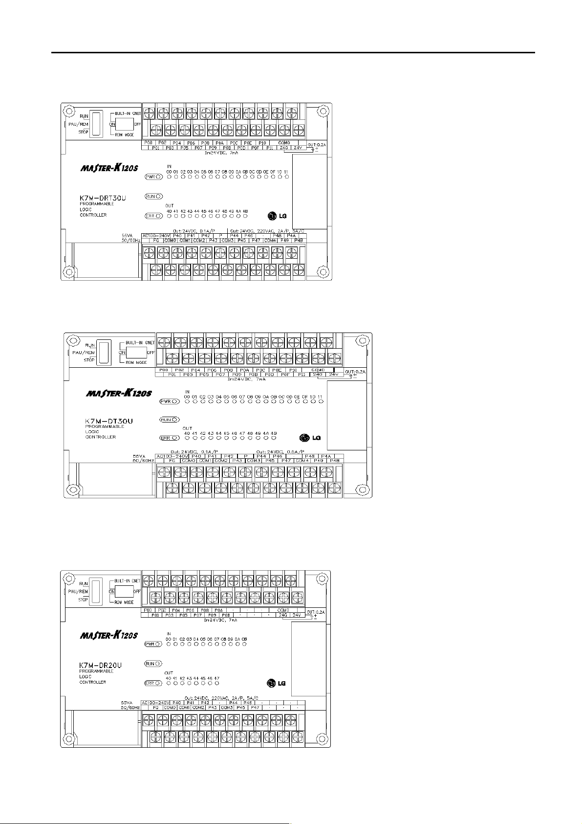
2) K7M-DRT30U
3) K7M-DT30U
4.1.4 20-points main unit (Standard)
1) K7M-DR20U
4 -5
Page 29
Chapter 4 Names of Parts
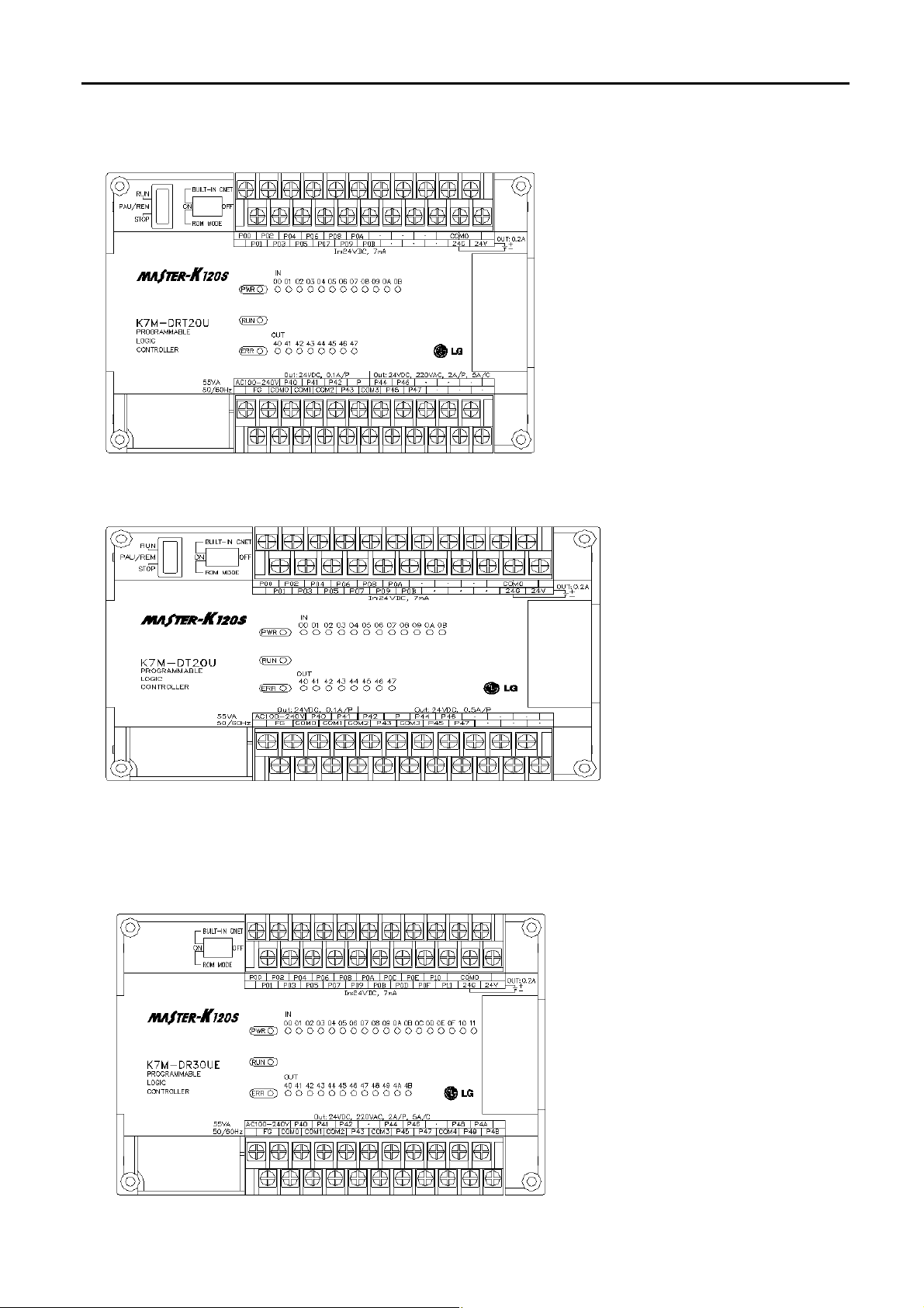
2) K7M-DRT20U
3) K7M-DT20U
4.1.5 30-points main unit (Economic)
1) K7M-DR30UE
4 -6
Page 30
Chapter 4 Names of Parts
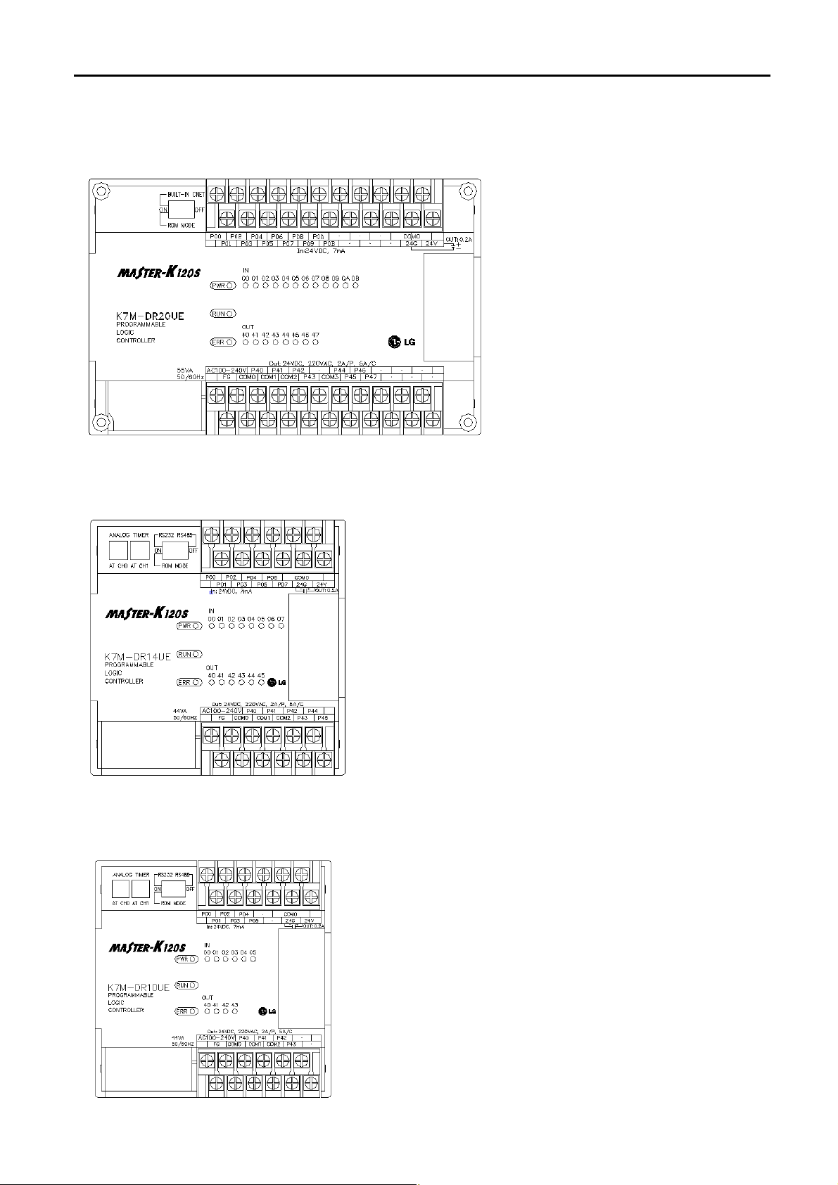
4.1.6 20-points main unit (Economic)
1) K7M-DR20UE
4.1.7 14-points main unit (Economic)
1) K7M-DR14UE
4.1.8 10-points main unit (Economic)
1) K7M-DR10UE
4 -7
Page 31

Chapter 4 Names of Parts
②
⑤③④
⑥
⑦
⑤
⑥⑧③④⑦
⑧
⑤⑤⑤⑥⑥
⑥
③④⑤
⑥
4.2 Expansion I/O Module
4.2.1 20points I/O Module
1) G7E-DR20A
4.2.2 10points I/O Module
1) G7E-DR10A
1) G7E-TR10A
②
①
①
No. Names
①
① Input LED
② Output LED
③ Input contact
④ Input common terminal
⑤ Output contact
⑥ Output common terminal
⑦ Expansion cable
⑧ Expansion Cable Connecting Terminal
No. Names
① Input LED
② Output LED
③ Input contact
④ Input common terminal
⑤ Output contact
②
⑥ Output common terminal
⑦ Expansion cable
⑧ Expansion Cable Connecting Terminal
No. Names
① Output LED
② Output contact
③ Output common terminal
④ External Power Supply Terminal (DC24V)
⑤ Expansion cable
⑥ Expansion Cable Connecting Terminal
4 -8
Page 32

Chapter 4 Names of Parts
③②③⑤④
③②③⑤④
4.2.3 8points I/O Module
1) G7E-DC08A
2) G7E-RY08A
②
No. Names
①
① Input LED
② Input contact
③ Input common terminal
④ Expansion cable
⑤ Expansion Cable Connecting Terminal
②
No. Names
①
① Output LED
② Output contact
③ Output common terminal
④ Expansion cable
⑤ Expansion Cable Connecting Terminal
4 -9
Page 33

Chapter 4 Names of Parts
⑦①②③④⑤⑥
4.3 Special Module
4.3.1 A/D·D/A Combination Module
1) G7F-ADHA
2) G7F-ADHB
③
No.
①
②
③
④
⑤
⑥
⑦
Names
RUN LED
Analog Output Terminal
Analog Input (Voltage/current) selecting jumper pin
Analog Input Terminal
External Power Supply Terminal (DC24V)
Expansion Cable
Expansion Cable Connecting Terminal
No.
Names
RUN LED
⑤
④
②
⑥
①
External Power Supply Terminal (DC24V)
Expansion Cable Connecting Terminal
Analog Input Terminal
Analog Output Terminal
Expansion Cable
4 -10
Page 34

Chapter 4 Names of Parts
①②③④⑤
①②③
④⑤⑥⑤③①④
②
4.3.2 D/A Conversion Module
1) G7F-DA2I
No.
Names
2) G7F-DA2V
①
②
③
④
RUN LED
Analog Output Terminal
Expansion Cable
Expansion Cable Connecting Terminal
External Power Supply Terminal (DC24V)
No.
Names
RUN LED
Analog Output Terminal
4.3.3 A/D Conversion Module
24V 24G
Input
Input
Select
CH0
V0 COM
I0
·
CH1 CH2 CH3
V1 COM
V2
I1
·
CH3
CH2
CH1
CH0
Expansion Cable
Expansion Cable Connecting Terminal
External Power Supply Terminal (DC24V)
COM
V3 COM
I2
I3
·
·
RUN LED
Analog Input Terminal
Analog Input (Voltage/current) selecting jumper
pin
External Power Supply Terminal (DC24V)
Expansion Cable
Expansion Cable Connecting Terminal
4 -11
Page 35

Chapter 4 Names of Parts
①②③④③①④②⑤
②
4.3.4 Analog timer Module
4.3.5 RTD Input Module
No.
①
②
③
④
Names
RUN LED
Analog Timer Volume Control Resistor
Expansion Cable
Expansion Cable Connecting Terminal
No.
①
②
Names
RUN LED
Analog Timer Volume Control Resistor
③
④
Expansion Cable
Expansion Cable Connecting Terminal
4 -12
Page 36

Chapter 4 Names of Parts
4.4 Communication I/F Module
4.4.1 Cnet I/F Module
1) G7L-CUEB
No. Names
① RS-232C connector
② Communication status LED
③ Expansion cable
④ Expansion cable connecting terminal
⑤ TM/TC selecting dip switch
2) G7L-CUEC
4.4.2 Fnet I/F Module
1) G7L-FUEA
No. Names
① RS-422/485 connector
② Power supply/Communication status LED
③ Expansion cable
④ Expansion cable connecting terminal
No. Names
① Station No. selecting switch
② Fnet cable connector 1 and 2
③ Expansion cable
④ Expansion cable connecting terminal
⑤ Communication status LED
4 -13
Page 37

Chapter 4 Names of Parts
4.4.3 Pnet I/F Module
1) G7L-PBEA
4.4.4 DeviceNet I/F Module
1) G7L-DBEA
No. Names
① Station No. selecting switch
② Pnet cable connector
③ Expansion cable
④ Expansion cable connecting terminal
⑤ Communication status LED
No. Names
① Station No. selecting switch(NA)
② DeviceNet cable connector
③ Expansion cable
④ Expansion cable connecting terminal
⑤ Baud rate selecting switch
⑥ Power supply/Communication status LED
4.5 Option Module
Option modules are attached the expansion slot of main unit or expansion unit, and supplies optional functions such as
memory expansion or real time clock. MASTER-K120S series have two option modules – External memory module and RTC
module.
No.
Names
①
Option module
②
4 -14
Connector
Page 38

Chapter 5 Power Supply / CPU
Chapter 5. Power Supply / CPU
5.1 Power Supply Specifications
5.1.1. Standard Type
Rated voltage
Rated frequency
Rated current
Input
Inrush current
Efficiency
Input fuse
Permitted Momentary
power failure
Output voltage
Output(1)
Output current
Output voltage
Output(2)
Output current
Power supply status indication
5.1.2. Economic Type
Items
DR/DRT/DT20U
K7M –
85 ~ 264 VAC
50 / 60 Hz (47 ~ 63 Hz)
0.5A(110VAC)/0.25A(220VAC) 0.6A(110VAC)/0.3A(220VAC)
Up to 30A Up to 60A
65% min.(rated input/maximum load)
2A/AC250V (Time Lag Type)
10 ms
DC 5V
1.2A 2A
DC 24V
0.2A
PWR LED On when power supply is normal
K7M –
DR/DRT/DT30U
K7M –
DR/DRT/DT40U
K7M –
DR/DRT/DT60U
Items K7M – DR10UE K7M – DR14UE K7M – DR20UE K7M – DR30UE
Rated voltage
Rated frequency
Rated current
Input
Inrush current
Efficiency
Input fuse
Permitted Momentary
power failure
Output voltage
Output(1)
Output current
Output voltage
Output(2)
Output current
Power supply status indication
85 ~ 264 VAC
50 / 60 Hz (47 ~ 63 Hz)
0.3A(110VAC) / 0.15A(220VAC) 0.5A(110VAC) / 0.25A(220VAC)
Up to 30A
65% min.(rated input/maximum load)
2A/AC250V (Time Lag Type)
10 ms
DC 5V
0.5A 1.2A
DC 24V
0.2A
PWR LED On when power supply is normal
5-1
Page 39

Chapter 5 Power Supply / CPU
5.2 CPU Specifications
The following table shows the general specifications of the MASTER-K120S series
5.2.1. Standard Type
Specifications
Items
K7M-DR/DRT/DT20U K7M-DR/DRT/DT30U K7M-DR/DRT/DT40U K7M-DR/DR`T/DT60U
Program control method Cyclic execution of stored program, Time-driven interrupt, Process-driven interrupt
I/O control method Indirect mode(Refresh method), Direct by program command
Program language Instruction list, Ladder diagram
Numbers of instructions Basic : 30, Application : 277
Remarks
Processing speed
Program capacity 10ksteps
I/O points 20 30 40 60
P P000 ~ P63F I/O relay,TR.
M M000 ~ M191F Auxiliary relay
K K000 ~ K31F Keep relay
L L000 ~ L63F Link relay
F F000 ~ F63F Special relay
Memory
device
T
0.1µs/step
100msec : T000 ~ T191 (192 points)
10msec : T192 ~ T250 (59 points)
1msec : T251 ~ T255 (5 points)
-. Adjustable by parameter setting
Timer
C C000 ~ C255 Counter
S S00.00 ~ S99.99
D D0000 ~ D4999 Data register
Operation modes RUN, STOP, PAUSE, DEBUG
Self-diagnosis functions Detects errors of scan time, memory, I/O and power supply
Data back-up method Latch area back-up
Up to 3 level
Max. expansion level
(External memory or RTC module can be connected as 4th expansion module)
5-2
Step controller
Page 40

Chapter 5 Power Supply / CPU
(continued)
Items
K7M-DR/DRT/DT20U K7M-DR/DRT/DT30U K7M-DR/DRT/DT40U K7M-DR/DRT/DT60U
Specifications
Remarks
Built-in
Function
PID control function
Cnet I/F Function
Capacity
High-
Counter function
speed
counter
Additional
function
Controlled by commands, Relay and PRC auto tuning,
PWM output, manual output, adjustable operation scan time,
Anti-windup, SV-Ramp, Delta MV, Position and Velocity algorithm
Dedicated protocol support
MODBUS protocol support RS-232C - 1port
User defined protocol support RS-485 - 1 port
No protocol support
1 phase : 100 kHz-2 channel, 20 kHz-2 channel
2 phase : 50 kHz-1 channel, 10 kHz-1 channel
4 different counter modes as following;
-. 1 phase operation mode.
-. 2 phase CW/CCW mode.
-. 2 phase Pulse + Direction mode.
-. 2 phase Multiplication mode(MUL4)
Internal/External preset function
Latch Counter function
RPM function
Comparison Output function
N0. of control axis : 2 Axis
Operation
Specification
Position-
Positioning
ing
Return to Origin
JOG Setting range : 5~100,000 ( High / Low speed)
Pulse catch
External interrupt
Input filter 0~1000ms(Adjustable)
Control method : Point-to-Point, Speed Control
Control unit : Pulse
Positioning data : 20 data / axis(Operation step N0. 1 ~ 20)
Positioning method : Absolute / Incremental
Operation method : Single / Repeat
Operation mode : End / Keep / Continuous
Address range : -2,147,483,648 ~ 2,147,483,647
Speed : Max. 100kpps(setting range 5 ~ 100,000)
Acceleration / Deceleration method : trapezoidal method
Origin detection when approximate origin turns off
Origin detection after deceleration when approximate origin turns on.
Origin detection by approximate origin.
Minimum pulse width : 10 ㎲( 2 points) and 50 ㎲(6 points)
10 ㎲(2 points) and 50 ㎲(6 points)
DRT / DT
Type Only
Weight (g) 520 540 660 850
5-3
Page 41

Chapter 5 Power Supply / CPU
5.2.2. Economic Type
Specifications
Items
K7M-DR10UE K7M-DR14UE K7M-DR20UE K7M-DR30UE
Program control method Cyclic execution of stored program, Time-driven interrupt, Process-driven interrupt
I/O control method Indirect mode(Refresh method), Direct by program command
Program language Instruction list, Ladder diagram
Numbers of instructions Basic : 30, Application : 269
Remarks
Processing speed
Program capacity 2ksteps
I/O points 10 14 20 30
P P000 ~ P63F I/O relay
M M000 ~ M191F Auxiliary relay
K K000 ~ K31F Keep relay
L L000 ~ L63F Link relay
F F000 ~ F63F Special relay
Memory
device
T
0.4µs/step
100msec : T000 ~ T191 (192 points)
10msec : T192 ~ T250 (59 points)
1msec : T251 ~ T255 (5 points)
-. Adjustable by parameter setting
Timer
C C000 ~ C255 Counter
S S00.00 ~ S99.99 Step controller
D D0000 ~ D4999 Data register
Operation modes RUN, STOP, PAUSE
Self-diagnosis functions Detects errors of scan time, memory, I/O and power supply
Data back-up method Latch area back-up
Up to 2 level
Max. expansion level
(External memory or RTC module can be connected as 3th expansion module)
5-4
Page 42

Chapter 5 Power Supply / CPU
(continued)
Items
Specifications
Remarks
K7M-DR10UE K7M-DR14UE K7M-DR20UE K7M-DR30UE
Built-in
Function
Cnet I/F Function
High-speed
counter
Pulse catch
External interrupt
Capacity
Counter
function
Additional
function
Dedicated protocol support
MODBUS protocol support RS-232C - 1port
User defined protocol support RS-485 - 1 port
No protocol support
1 phase : 10 kHz-2 channel
2 phase : 5 kHz-1 channel
4 different counter modes as following;
-. 1 phase operation mode.
-. 2 phase CW/CCW mode.
-. 1 phase Pulse + Direction mode.
-. 2 phase Multiplication mode(MUL4)
Internal/External preset function
Latch Counter function
RPM function
Comparison Output function
Minimum pulse width : 50 ㎲(4 points)
50 ㎲(4 points)
RS-485 is available
on K7M-DR10/14UE
only
Input filter 0 ~ 1000ms(Adjustable)
Weight (g) 360 370 500 510
5-5
Page 43

Chapter 5 Power Supply / CPU
A
5.3 Operation Processing
5.3.1 Operation Processing Method
1) Cyclic operation
A PLC program is sequentially executed from the first step to the last step, which is called scan. This sequential
processing is called cyclic operation. Cyclic operation of the PLC continues as long as conditions do not change
for interrupt processing during program execution. This processing is classified into the following stages:
Stages Processing
Operation Start
-
Initialization
Stage for the start of a scan processing. it is executed only one
time when the power is applied or reset is executed. It executes
the following processing..
▶ I/O reset
▶ Execution of self-diagnosis
▶ Data clear
llocating I/O address and type
▶
Input image area refresh
Input conditions are read and stored into the input image area
before starts processing.
Program operation processing
Program is sequentially executed from the first step to the last step
Program operation processing
Program starts
~
Program ends
Output image area refresh
The contents stored in the output image area is output to output part
when operation processing of a program is finished.
END processing
Stage for return processing after the CPU part has finished 1 scan.
The END processing following processing is executed.
▶ Self-diagnosis
▶ Change the present values of timer and counter, etc.
▶ Processing data communications between computer link module
and communications module.
▶ Checking the switch for mode setting.
5-6
Page 44

Chapter 5 Power Supply / CPU
r
r
2) Interrupt operation method
If a situation occurs which is requested to be urgently processed during execution of a PLC program, this opera
tion method processes immediately the operation, which corresponds to interrupt program. The signal, which infor
ms the CPU of those urgent conditions is called interrupt signal. The MASTER-K120S CPU has three kind of int
errupt operation methods, which are internal, external and high speed counter interrupt signal methods.
5.3.2 Operation Processing at Momentary Power Failure Occurrence
The momentary power failure occurs when the input line voltage to the power supply falls down below the rated
voltage. When momentary power failure within 10ms occurs, the CPU maintain operation processing. But If is exceeds
10ms, CPU stop processing and all output turns off. And The re-start process is executed as the power is re-applied.
1) Momentary power failure within 10 ms
Input powe
Momentary power failure
within 1Oms
2) Momentary power failure exceeding 10 ms
Input powe
Power failure exceeding 1Oms
→ The operation processing is maintained
→ The re-start process is executed as the power is re-applied.
REMARK
1) Momentary power failure
The PLC defining power failure is a state that the voltage of power has been lowered outside the allowable
variation range of it. The momentary power failure is a power failure of short interval (several to tens ms).
5-7
Page 45

Chapter 5 Power Supply / CPU
5.3.3 Scan Time
The processing time from a 0 step to the 0 step of next scan is called scan time.
1) Expression for scan time
Scan time is the sum of the processing time of scan program that the user has written, of the task program processing time
and the PLC internal processing time.
(1) Scan time = Scan program processing time + Interrupt program processing time + PLC internal processing time
• Scan program processing time = The processing time used to process a user program that is not specified
to a task program.
• Interrupt program processing time = Total of the processing times of interrupt programs executed during
one scan.
• PLC internal processing time = Self-diagnosis time + I/O refresh time + Internal data processing time
+ Communications service processing time
(2) Scan time differs in accordance with the execution or non-execution of interrupt programs and communications
processing, etc.
2) Flags
Scan time is stored in the following system flag area.
• F50 : Maximum scan time (unit: 1 ms)
• F51
: Minimum scan time (unit: 1 ms)
• F52 : Current scan time (unit: 1 ms)
5.3.4 Scan Watchdog Timer
1) Watchdog timer is used to detect a delay which is attributable to abnormal operation of sequence program
(Watchdog time is set in menu of basic parameter of KGLWIN.)
2) When watchdog timer detects an exceeding of preset watchdog time, the operation of PLC is stopped immediately
and all output is off.
3) If an exceeding of preset watchdog time is expected in sequence program, use ‘WDT’ instruction.
‘WDT’ instruction make elapsed watchdog time as zero.
4) In order to clear watchdog error, restarting the PLC or mode change to STOP mode are available.
REMARK
-. Setting range of watchdog : 10 ~ 6,000ms(unit : 10ms)
5-8
Page 46

Chapter 5 Power Supply / CPU
p
5.3.5 Timer Processing
The MASTER-K series use up count timer. There are 5 timer instructions such as on-delay (TON), off-delay (TOFF), integral
(TMR), monostable (TMON), and re-triggerable (TRTG) timer.
The measuring range of 100msec timer is 0.1 ~ 6553.5 seconds, 10msec timer is 0.01 ~ 655.35 seconds, and that of 1msec
timer is 0.001 ~ 65.53 seconds. Please refer to the ‘MASTER-K programming manual’ for details.
1) On delay timer
The current value of timer starts to increase from 0 when the input condition of TON instruction turns on. When the
Preset value
Timer output relay
Timer type
current value reaches the preset value, the timer output relay turns on.
When the timer input condition is turned off, the current value becomes 0 and the timer output relay is turned off.
input condition
Output relay
Pre value
t0
t0+PT
t1 t2 t3
t4
t5
t5 t4+PT
Current value
t0 t1
t2 t3 t4 t5
2) Off delay timer
The current value of timer set as preset value and the timer output relay is turned on when the input condition of TOFF
instruction turns on. When the input condition is turned off, the current value starts to decrease. The timer output relay is
turned off when the current value reaches 0.
Timer input condition
t0
t1
t2 t4
t3
t5
Timer out
Preset value
ut relay
PT
t5 + PT t1 + PT
PT
Current value
5-9
Page 47

Chapter 5 Power Supply / CPU
3) Integral timer
In general, its operation is same as on-delay timer. Only the difference is the current value will not be clear when the
input condition of TMR instruction is turned off. It keeps the elapsed value and restart to increase when the input
condition is turned on again. When the current value reaches preset value, the timer output relay is turned on.
The current value can be cleared by the RST instruction only.
Timer input condition
Timer output relay
Preset value
Current value
Timer reset input
t0 t1 t2
t0
t4
PT = (t1-t0)+(t3-t2)
t2
t1
t3
t5
t5
t5+PT
4)
Monostable timer
In general, its operation is same as off-delay timer. However, the change of input condition is ignored while the timer is
operating (decreasing). When current value reaches preset value the timer output relay is turned off and current value is
cleared.
Timer input condition
Timer output relay
Preset value
t0
t0
t0+PT
t1
t2
t3
t2
t2+PT
t4
t4
t4+PT
Current value
t0
t1
t2
t4
5 - 10
Page 48

Chapter 5 Power Supply / CPU
5) Retriggerable timer
The operation of retriggerable timer is same as that of monostable timer. Only difference is that the retriggerable timer is
not ignore the input condition of TRTG instruction while the timer is operating (decreasing). The current value of
retriggerable timer will be set as preset value whenever the input condition of TRTG instruction is turned on.
Timer input condition
Timer output relay
Preset value (PV)
Current value
PT
(On operation)
REMARK
The Maximum timing error of timers of MASTER-K series is ‘1 scan time + the time from 0 step to timer instruction’
5 - 11
Page 49

Chapter 5 Power Supply / CPU
5.3.6 Counter Processing
The counter counts the rising edges of pulses driving its input signal and counts once only when the input signal is switched
from off to on. MASTER-K series have 4 counter instructions such as CTU, CTD, CTUD, and CTR. The followings shows
brief information for counter operation. Refer to the ‘MASTER-K Instruction Manual’ for details.
1) Up counter (CTU)
-. The counter output relay is turned on when the current value reaches the preset value.
-. When the reset input is turned on, the counter output relay and current value is cleared as 0.
2) Down counter (CTD)
-. When the CPU is switched to the RUN mode, the current value is set as preset value.
-. The current value is decreased by 1 with the rising edge of counter input signal.
-. The counter output relay is turned on when the current value reaches 0.
3) Up-down counter
-. The current value is increased with the rising edge of up-count input signal, and decreased with the rising edge of
down-count input signal.
-. The counter output relay is turned on when the current value is equal or greater than the preset value otherwise off.
5 - 12
Page 50

Chapter 5 Power Supply / CPU
4) Ring counter
-. The current value is increased with the rising edge of the counter input signal, and the counter output relay is turned on
when the current value reaches the preset value. Then the current value and counter output relay is cleared as 0 when
the next counter input signal is applied.
5) Maximum counting speed
(1) The maximum counting speed of counter is determined by the length of scan time. Counting is possible only when the
on/off switching time of the counter input signal is longer than scan time.
)(C speed counting Maximum max
100
n
1
×=
times/sec)(
t
s
where, n : duty (%), ts : scan time
(2) Duty
Duty is the ratio of the input signal’s on time to off time as a percentage.
If T1 ≤ T2,
If T1 > T2,
T1 T2
OFF ON
T1
n (%100×
=
T2T1
+
T2
n (%100×
=
T2T1
+
OFF
)
)
5 - 13
Page 51

Chapter 5 Power Supply / CPU
g
5.4 Program
5.4.1 Classifications of Program
All functional elements need to execute a certain control process are called as a ‘program’. In MASTER-K120 series, a
program is stored in the EEPROM mounted on a CPU module or flash memory of a external memory module. The following
table shows the classification of the program.
Program type Description
Scan program The scan program is executed regularly in every scan
Time-driven interrupt
program (TDI)
Process driven interrupt
program (PDI)
High speed counter driven
interrupt program(HSCDI)
Subroutine program
The TDI programs are executed with a constant time interval specified with parameter settin
The PDI programs are executed when external interrupt input is applied and the corresponding
interrupt routine is enabled by EI instruction.
This interrupt programs are executed when comparison task signal is applied.
(Standard Type only)
The subroutine programs are executed when they are called by the scan program with a CALL
instruction.
5.4.2 Program Execution Procedure
The following diagram shows that how the CPU module process programs when the CPU module is powered on or switched to
RUN mode.
Start processing
.
Scan program
HSCDI program
END processing
5 - 14
Subroutine program
PDI program
TDI program
Page 52

Chapter 5 Power Supply / CPU
1) Scan program
-. The scan program is executed regularly in every scan from 0 step to last step.
-. When interrupts has occurred, CPU pauses scan program and executes corresponding interrupt program first.
-. When this interrupt program finished, scan program is to resume.
2) Interrupt program
-. When an interrupt occurs, the CPU module will stop the current operation and execute the corresponding interrupt routine
first. After finish the interrupt routine, the CPU resume the sequence program from the stopped step.
-. MASTER-K102S series provides 3 types of interrupt.
• The TDI (Time driven interrupt) occurs with the constant period
• The PDI (Process driven interrupt) occurs with the status of external input.
• The HSCDI(High speed counter driven interrupt) occur with comparison task signal from high speed counter.
(Standard type only)
5.4.3 Interrupt Programs
1) Usage of interrupt program
(1) Before to use interrupt function in sequence program, the parameter setting should be done properly. Then the
corresponding interrupt routine should be written after END instruction. (Refer chapter 4 for details) If interrupt routines
are not matched with parameter settings, an error occurs and the operation of CPU will be stopped.
(2) To execute an interrupt routine, use the EI instruction to enable the corresponding interrupt. The interrupt routine is not
executed if an interrupt factor occurs before execution of an EI instruction. Once an interrupt is enabled with EI
instruction.
(3) When multiple interrupt factors occur simultaneously, interrupt routines are executed according to the priority given to
the each interrupt. If an interrupt factor that has higher priority occurs while other interrupt that has lower priority are
executing, the interrupt routine of lower priority will be stopped and the interrupt of higher priority will be executed first.
Following figure show how CPU handles multiple interrupts
1
Program starts
2
2
Interrupt 2 occurs
Scan Program
1
Interrupt routine 1
Interrupt routine 2
7
5
3
6
3
Stop main program and execute interrupt routine 2
4
Interrupt 1 occurs (higher priority)
5
Stop routine 2 and run routine 1
6
Finish routine 1 and return to routine2
4
7
Finish routine 2 and return to main program
5 - 15
Page 53

Chapter 5 Power Supply / CPU
2) parameter setting
3) Time driven interrupt
TDI occurs periodically with the constant interval assigned in parameter setting. The interrupt routine of TDI starts with the
TDINT instruction and ends with the IRET instruction.
When multiple interrupt factors occur simultaneously, interrupt routines are executed according to the priority given to the
each interrupt. If an interrupt factor has higher priority occurs while other interrupt of lower priority is executing, the interrupt
routine of lower priority will be stopped and the interrupt of higher priority will be executed first. In standard types of MK120S
series, Available TDI is P000 ~ P007 (8 points) assigned in parameter setting and period can be designated for each other.
In economic types, Available TDI is P000 ~ P003 (4 points) .
4) Process driven interrupt
In standard types of MK120S series, Available PDI is P000 ~ P007 (8 points) assigned in parameter setting.
In the parameter setting window, TDINT indicates time driven interrupt and INT indicates process driven interrupt.
PDI occurs when the input status of P000 ~ P007 is changed from Off to On or from On to Off or both.
In economic types of MK120S series, Available PDI is P000 ~ P003 (4 points), and occurs when the input status of P000 ~
P003 is changed from Off to On. It isn’t occurs falling edge of input condition.
5) HSC driven interrupt
HSCDI occurs when comparison task of HSC occurs and Available HSCDI is Ch0 ~ Ch4 (4 points) .
5 - 16
Page 54

Chapter 5 Power Supply / CPU
REMARK
Total available interrupt points is 8(In standard type).
-. Time driven interrupt + process driven interrupt + high speed counter driven interrupt ≤ 8 points
Interrupt signal is ignored when self-interrupt occurs more than 2 times during interrupt processing is executing.
ignored
Interrupt executing time
Interrupt signal (ex : rising edge)
5.4.4 Error Handling
1) Error Classification
Errors occur due to various causes such as PLC system defect, system configuration fault or abnormal operation
result. Errors are classified into fatal error mode, which stops system operation for system stability, and ordinary
error mode, which continues system operation with informing the user of its error warning.
The main factors that occurs the PLC system error are given as followings.
• PLC hardware defect
• System configuration error
• Operation error during execution of the user programs
• External device malfunction
2) Operation mode at error occurrence
In case of error occurrence, the PLC system write the error contents the corresponding flags and stops or conti
nues its operation complying with its operation mode.
(1) PLC hardware defect
The system enters into the STOP state if a fatal error such as the CPU module defect has occurred, and
continues its operation if an ordinary error such as operation error has occurred.
(2) System configuration error
This error occurs when the PLC hardware configuration differs from the configuration defined in the
K120S series. The system enters into the STOP state.
(3) Operation error during execution of the user programs
It the numeric operation error of these errors occurs during execution of the user program, its contents are
marked on the error flags and the system continues its operation. If operation time overruns the watchdog
time or I/O modules loaded are not normally controlled, the system enters into the STOP state.
5 - 17
Page 55

Chapter 5 Power Supply / CPU
(4) External device malfunction
The PLC user program detects malfunctions of external devices. If a fatal error is detected the system ent
ers into the STOP state, and if an ordinary error is detected the system continues its operation.
REMARK
1) In occurrence of a error, the state is to be stored in the representative system error flag F006.
2) For details of flags, refer to Chapter 11. Troubleshooting.
5 - 18
Page 56

Chapter 5 Power Supply / CPU
t
5.5 Operation Modes
The CPU operates in one of the four modes - RUN, STOP, PAUSE and DEBUG mode. The following describes ope
ration processing in each operation mode.
5.5.1 RUN Mode
In this mode, programs are normally operated.
The first scan start in the RUN mode
Initialize data area according to the prese
restart mode.
Check the program and determine it can be
executed or not.
Execute input refresh
Execute programs and tasks
Check the availability of expansion units
Execute communication and internal service
Execute output refresh
No
Operation mode is changed?
Yes
Operate with new mode
1) Processing when the operation mode is changed.
Initialization of data area is executed when the first scan starts and The possibility of execution of the program
is decided with check on its effectiveness.
2) Operation processing contents
I/O Refresh and program operation are executed.
(1) Interrupt programs are executed with the detection of their start-up conditions.
(2) Normal or abnormal operation and mounting conditions of the loaded module are checked.
(3) Communications service or other internal operations are processed.
5 - 19
Page 57

Chapter 5 Power Supply / CPU
5.5.2 STOP mode
In this mode, programs are not operated.
1) Processing when the operation mode is changed.
The output image area is cleared and output refresh is executed.
2) Operation processing contents
(1) I/O refresh is executed.
(2) Normal or abnormal operation and mounting conditions of the loaded module are checked.
(3) Communications service or other internal operations are processed.
5.5.3 PAUSE mode
In this mode, the program operation is temporarily stopped. If it returns to the RUN mode, the operation continu
es from the state before the stop.
1) Processing when the operation mode changes
Data registers and input image areas are not cleared and the operating conditions just before the mode chang
e is maintained.
2) Operation processing contents
(1) I/O refresh is executed.
(2) Normal or abnormal operation and mounting conditions of the loaded module are checked.
(3) Communications service or other internal operations are processed.
5.5.4 DEBUG mode(Standard type only)
In this mode, errors of a program are searched and the operation sequence is traced. Changing into this mode
is only possible from the STOP mode. In this mode, a program can be checked with examination on its executi
on state and contents of each data.
1) Processing when the operation mode changes
(1) Data area is initialized at the starting time of the mode change complying with the restart mode, which
has been set on the parameters.
(2) The output image area is cleared and input refresh is executed.
2) Operation processing contents
(1) I/O refresh is executed.
(2) Debugging process is executed complying with setting. I
(3) I/O refresh is executed after debugging process has executed to end of the program
(4) Normal or abnormal operation and mounting conditions of the loaded module are checked.
(5) Communications service or other internal operations are processed
5 - 20
Page 58

Chapter 5 Power Supply / CPU
3) Debug operation conditions
following four operation conditions can be specified.
Operation conditions Description
executed by one
command.
executed by break-point
settings.
When executed, Stop operation after executing one instruction
When executed, Stop operation at designated break-point
executed by the
condition of the device
executed by the
specified scan time
4) Operation method
(1) Execute the operation after the debug operation conditions have been set in the KGLWIN.
(2) In interrupt programs, each task can be specified to operation enable/disable.
For detailed operation method, refer to the KGLWIN User’s Manual Chapter 9.
5.5.5 Operation Mode Change
1) Operation mode change methods
The following method is used to change the operation mode.
(1) Change by the mode-setting switch of CPU module.(Standard type only)
(2) Change by the KGLWIN connected with the CPU module communications port.
(3) Change by the KGLWIN connected to the remote CPU module through Cnet I/F
When executed, Stop operation by condition of designated device’s status
When executed, Operates specified scan time.
(4) Change by the ‘STOP’ instruction, during program execution.
(5) Change by the KGLWIN connected to the remote CPU module through Fnet(Standard type only)
2) Operation mode change by the mode-setting switch of CPU module.(Standard type only)
The following shows the operation mode change by the mode-setting switch of CPU module.
Mode setting switch position Operation mode
RUN Local RUN
STOP Local STOP
STOP → PAU / REM
PAU / REM → RUN ∗ 1
RUN → PAU / REM * 2
PAU / REM → STOP
REMARK
-. If the operation mode changes from RUN mode to local RUN mode by the mode setting switch, the
PLC operates continuously without stopping.
Remote STOP
Local RUN
Local PAUSE
Local STOP
5 - 21
Page 59

Chapter 5 Power Supply / CPU
3) Mode change Remote operation
Remote operation mode change is available only when the operation mode is set to the remote STOP mode
(i.e., the mode setting switch position is in the STOP→ PAU/REM’).
Mode setting switch
position
Mode Change
Mode change by the
KGLWIN
Mode change using
FAM or Cnet I/F, etc.
Remote STOP Æ Remote RUN
Remote STOP Æ Remote PAUSE X X
Remote STOP Æ DEBUG
Remote RUN Æ Remote PAUSE
Remote RUN Æ Remote STOP
PAU / REM
Remote RUN Æ DEBUG X X
Remote PAUSE Æ Remote RUN
Remote PAUSE Æ Remote STOP
Remote PAUSE Æ Remote DEBUG X X
DEBUG Æ Remote STOP
DEBUG Æ Remote RUN X X
DEBUG Æ Remote PAUSE X X
○ ○
○ ○
○ ○
○ ○
○ ○
○ ○
○ ○
5 - 22
Page 60

Chapter 5 Power Supply / CPU
5.6 Functions
5.6.1 Self-diagnosis
1) Functions
(1) The self-diagnosis function permits the CPU module to detect its own errors.
(2) Self-diagnosis is carried out when an error occurs during PLC power supply is turned on or operating process.
If an error is detected, the system stops operation to prevent faulty PLC operation.
2) WDT (Watch dog timer) function
The watch dog timer is an internal timer of a PLC to detect the error of hardware and a sequence program. it is
changeable with parameter setting.
The CPU resets the watch dog timer before step 0 is executed (after the END processing is finished). When the END
instruction has not been executed within the set value due to an error occurred in the PLC or the delay of a sequence
program, the watch dog timer will times out. When a watch dog timer error is occurred, all outputs of the PLC are turned
OFF, and the ERR LED of the CPU will flickers. (RUN LED will be turned OFF) Therefore, when use FOR ~ NEXT or
CALL instruction, insert WDT instruction to reset the watch dog timer.
Refer the MASTER-K programming manual for details on the parameter setting.
0 WDT END 0 END
WDT Reset WDT Reset WDT Reset
3) I/O module check function
Mounting conditions of the loaded module are checked
4) Error history
When error occurs, Corresponding error code is stored in special relay F006.
5 - 23
Page 61

Chapter 5 Power Supply / CPU
5.6.2 I/O Force On/Off function
It is possible to input/output a designated data regardless of the program operation results. When used with OUTOFF
instruction simultaneously, OUTOFF is prior to I/O Force On/Off.
1) Forced I/O setting method.
-. I/O Force on/off setting is applied to input area and output area.
-. I/O Force on/off should be set for each input and output, the setting operates from the time that
Force I/O setting enable’ is set.
-. This setting can be done when I/O modules are not really loaded.
-. Select the ’set forced I/O’ from KGLWIN
-. Select the I/O area and then double click.
Click
5 - 24
Page 62

Chapter 5 Power Supply / CPU
-. When forced I/O set enables, forced I/O function is executing.
Set ‘forced I/O data’ by bit
Set ‘forced I/O data enable’ by bit
Click
5 - 25
Page 63

Chapter 5 Power Supply / CPU
2) Special data register for forced I/O
The contents of forced I/O setting is registered to special data register as below.
It is possible to use ‘forced I/O function’ to program.
Items Special Device
All Forced I/O enable M1910
Forced I/O enable by bit D4700 ~ D4763
Forced I/O set data D4800 ~ D4863
3) Force on/ off Processing timing and method
(1) Forced Input
After data have been read from input modules, at the time of input refresh the data of the junctions which
have been set to force on/off will be replaced with force setting data to change the input image area. And
then, the user program will be executed with real input data and force setting data.
(2) Forced output
When a user program has finished its execution the output image area has the operation results. At the time
of output refresh the data of the junctions which have been set to force on/off will be replaced with force se
tting data and the replaced data will be output. However, the force on/off setting does not change the output
image area data while it changes the input image area data.
(3) Precautions
y Turning the power off and on, changes of the operation mode or operation by reset switch does not change
the previous force on/off setting data. They remain within the CPU module and operation is executed with
the same data.
y Forced I/O data will not be cleared even in the STOP mode.
y When setting new data, disable every I/O settings using the setting data clear function and set the new data.
REMARK
-. For detailed operation, refer to the KGLWIN user’s Manual Chapter 7 ‘Force I/O setting.
5 - 26
Page 64

Chapter 5 Power Supply / CPU
5.6.3 Direct I/O Operation function
This function is useful when reads an input relay’s state directly during execution of a program and uses in the operation, or
write the operation result directly to an output relay. Direct input/output is executed by the ‘IORF’ instruction. If this instruction is
used, the input/output image area will be directly updated and applied to the continuing operations.
REMARK
-. For detailed operation, refer to the ‘MASTER-K Manual for instruction’.
5.6.4 System error history
When the system is stopped by error occurrence, the CPU stores the error occurrence time and error code to the special data
register area. The most recent 16 error occurring times and error codes are stored in the special data register.
1) Special data register for error history
Data area Description
D4901 ~ D4904
D4905 ~ D4908 The 2nd error information :
Device
D4961 ~ D4964 The 16
2) Description of each word
Data area Contents Description
D4900 H0001 Error occurred point
D4901 H0305 Year : 03, Month : 5
D4902 h2812 Date : 28, Hour : 12
D4903 h3030 Minute : 30, Second : 30
D4904 h0001 Error code (h0001)
3) Clear error data
st
The 1
error information, The 17th error information
: :
th
error information
Use a ‘data clear’ function of KGLWIN.
REMARK
Refer to the KGLWIN user’s Manual Chapter 7, for details.
5 - 27
Page 65

Chapter 5 Power Supply / CPU
(
)
5.7 Memory Configuration
The CPU module includes two types of memory that are available by the user. One is program memory, which is
used to store the user programs written to implement a system by the user. The other is data memory, which sto
res data during operation.
Bit Data Area
0 ~ F 0000 ~ FFFF
I/O relay
Auxiliary relay
(3,040 points)
Special auxiliary relay
(32 points)
Keep relay
(512 points)
Special relay
(1,024 points)
Link relay
(1,024 points)
M000
M189
M190
M191
K00
P00
P63
K31
F00
F63
L00
L63
“P”
“M”
“M”
“K”
“F”
“L”
D0000
D4500
D4999
T255
T000
T255
C000
C255
C000
Word Data Area User Program Area
Data Register
Reserved for special usage
“D”
Word
Parameter setting area
User Program Area
(10ksteps)
Timer preset value
(256 words)
Timer elapsed value
(256 words)
Counter preset value
(256 words)
Counter elapsed value
256 words
(economic type : 2ksteps)
T000
T191
T192
T250
T251
T255
C000
C255
Timer (100ms)
192 points
Timer (10ms)
59 points
Timer (1ms)
5 points
Counter
“T”
“T”
“T”
“C”
S00
S99
Step Controller
(100 x 100 steps)
S00.00~S99.99
5 - 28
“S”
Page 66

Chapter 5 Power Supply / CPU
5.8 I/O Address Allocation
I/O No. allocation means to give an address to each module in order to read data from input modules and output data to
output modules.
Expansion I/O module 3 2 modules in economic type
Max. 3 expansion module is available in standard type.
Mounting module Max. module can be mounted remark
A/D, D/A conversion module 3
Analog timer module 3
Communication module 1
1) I/O No. allocation method
-. Basically, I/O allocation is fixed point method.(the area which is not used can be used internal relay)
-. The special module is not allocated.
Module I/O Allocation Remark
Main
Expansion #1
Expansion #2
Expansion #3
Not available on economic type
Input P000 ~ P03F Fixed 64 points
Output P040 ~ P07F Fixed 64 points
Input P080 ~ P08F Fixed 16 points
Output P090 ~ P09F Fixed 16 points
Input P100 ~ P10F Fixed 16 points
Output P110 ~ P11F Fixed 16 points
Input P120 ~ P12F Fixed 16 points
Output P130 ~ P13F Fixed 16 points
Special None A/D,A/T,Communication
5 - 29
Page 67

Chapter 5 Power Supply / CPU
5.9 Built-in Cnet Selection Switch
5.9.1 Structure
You can see dip switches as shown when you open I/O terminal block cover.
5.9.2 Usage
BUILT_IN CNET
ON
ROM MODE
Dip switch position Description
OFF
Terminal block cover
upper switch is for Cnet.
ON
ROM MODE
Upper switch is for Cnet.
ON
* The lower switch is for O/S download setting. Don’t handle this switch.
ROM MODE
OFF
OFF
Turn upper switch on to use built-in RS-232C communication
Turn upper off switch to use external communication modules.
5 - 30
Page 68

Chapter 5 Power Supply / CPU
Dip switch for Built-in Cnet is placed in deep place to prevent a mistaken operation caused by terminal block cover, etc. Use
a small driver to operate it.
Driver
Dip switch
Terminal block cover
5 - 31
Page 69

Chapter 5 Power Supply / CPU
5.10 External Memory Module
MK120S series supplies external memory module for the user to save programs safely or download a program on the
system and use it in case of a program is damaged.
5.10.1 Structure
5.10.2 Usage
Installation connector
1) Saving the user’s program on the external memory module.
(1) Turn the power of the base unit off.
(2) Install the memory module.
-. When only main unit is used : Connect to the expansion connector of the basic unit.
-. When expansion units are used : Connect to the expansion connector of the last connected expansion unit.
(3) Turn the power of the main unit on.
(4) Connect KGLWIN and PLC.
(5) Select Online –Read Information – I/O Information in menu, and the following message box will displayed
5 - 32
Page 70

Chapter 5 Power Supply / CPU
(6) Select Online – Flash memory – Write to external memory in menu, and the following message box will displayed.
(7) Turn the power of the main unit off.
(8) Remove the external memory module.
Through the above steps a user can save a program into the external memory module.
2) Run the PLC with a program of external memory module
(1) Turn the power of the main unit off.
(2) Install the memory module
- When only main unit is used, connect to the expansion connector of the main unit And when expansion unit is used,
connect to the expansion connector of the last connected expansion unit.
(3) Turn on the power of the main unit.
Through the above steps the user can operate the PLC with program stored in the external memory module.
REMARK
1) When the PLC restarts, it always operated with the external memory module automatically if external memory is
connected.
2) Remove after writing is finished.
5 - 33
Page 71

Chapter 5 Power Supply / CPU
5.11 RTC Module
MK120S series supplies RTC(Real Time Clock) module for the time-scheduling control. To use RTC function with K120S series,
the RTC operation module should be attached to the expansion slot of main unit or expansion module. Clock operation by the
RTC function is continued with a super capacitor when the CPU is powered off.
5.11.1 Structure
5.11.2 Usage
1) Read RTC data
(1) Read RTC data from KGLWIN
-. Select Online –Write Information – Set PLC Clock in menu.
Installation connector
-. Following message box will be displayed
5 - 34
Page 72

Chapter 5 Power Supply / CPU
(2) Read RTC data from special register
Special register Area
(Word)
F053 Lower 2 digits of year Month H0207
F054 Day Hour H2313
F055 Minute Second H5020
F056 Higher 2 digits of year Date H2002
Example : 2002. 07. 23. 13:50:20, Tuesday
Upper byte Lower byte
2) Write RTC data
There is two ways to write new RTC data to the CPU.
The first one is using a graphic loader (KGLWIN). For detailed information, refer the user’s manual of KGLWIN.
The second one is write sequence program. By switching a special bit on, user can replace the current RTC data with the
reset data stored in a specified memory area. The followings are the memory address of preset data and an example
Description
Data
(BCD format)
program.
Data register Area
(Word)
D4993 Lower 2 digits of year Month H0207
D4994 Day Hour H1011
D4995 Minute Second h5324
D4996 Higher 2 digits of year Date H2001
Example : 2002. 7. 10. 11:53:24, Monday
* M1904 : RTC data change bit
When the M1904 bit is switched on, the new data in D4993 ~ D4996 will be moved to F53 ~ F56. After data is
moved, M1904 has to be switched off immediately because current data will be updated every scan while
M1904 is on.
Upper byte Lower byte
3) Date expression
Description
Data
(BCD format)
Number 0 1 2 3 4 5 6
Date Sunday Monday Tuesday Wednesday Thursday Friday Saturday
REMARK
1) If RTC stops or error occurs, write new data to the RTC then error is called off.
2) There is no written clock data in the RTC when shipped.
3) Before using RTC module, write clock data to the RTC first
5 - 35
Page 73

Chapter 6 Input and Output Specification
Chapter 6 Input and Output Specification
6.1 Input / Output Specifications
Digital input that offers to MASTER-K120S series are made to use both of electric current sink and electric current source.
To keep use coil load as an output module, maximum opening and shutting frequency is 1 second on and 1 second off.
The following diagram shows maximum life relay for relay output.
Frequency (
100
×
10,000)
50
30
20
10
0.5
AC 125V r/load
DC 30V r/load
AC 250V r/load
3 2 1
Opening/shutting of electric current
10 5
100(A)
6-1
Page 74

Chapter 6 Input and Output Specification
6.2 Digital Input Specification
6.2.1 Main unit
1) Specification
K7M-
Main unit
DR/DRT/DT30U
K7M-DR30UE
K7M-
K7M-
DR/DRT/DT40U
K7M-DRT40U
Model
Specification
Number of input points 6 points 8 points 12 points 18 points 24 points 36 points
Insulation method Photo coupler
Rated input voltage DC 24V
Rated input current 7 mA (Standard Type P0~P3:9mA, Economic Type P0,P1:9mA)
Operating voltage range DC20.4 ~ 28.8V (ripple: less than 5%)
Max. simultaneous input points 100% simultaneously On
On voltage / On current DC19V or higher / 5.7 mA or higher
Off voltage / Off current DC6V or lower / 1.8 mA or lower
Input impedance
Response time
Off → On
On → Off
K7M-DR10UE K7M-DR14UE
Approx.3.3 kΩ(Standard Type P0~P3:2.7 kΩ, Economic Type P0,P1:2.7 kΩ)
0,1,2,5,10,20,50,100,200,500,1000ms (Default : 10ms)
0,1,2,5,10,20,50,100,200,500,1000ms (Default : 10ms)
DR/DRT/DT20U
K7M-DR20UE
K7M-
DR/DRT/DT60U
K7M-DRT60U
Common terminal 6 points / COM 8 points/COM 12 points/COM 18 points/ COM 12points/COM 18points/COM
Operating indicator LED turns on at ON state of input
2) Circuit diagram
COM
COM
R
R
R
R
C
Internal
circuit
Internal
circuit
Standard Type P000 ~ P001
Economic Type None
Standard Type P002 ~
Economic Type P000 ~
6-2
Page 75

Chapter 6 Input and Output Specification
3) Input wiring
Main unit’s wiring method is as follows. DC input specifications offered by MASTER-K120S is to be used for both electric
current sink and electric current source.
(1) Main unit
DC24V DC24V
6-3
Page 76

Chapter 6 Input and Output Specification
r
4) Example of external devices.
To connect with external device of DC output type into DC input module, wire depending on the type of the external device
as shown.
External device
Input
Contact points
Relay
7mA
IN
COM
NPN open collector output type
7mA
7mA
Power fo
sensor
Power for
sensor
IN
COM +
Same power for sensor
and input
IN
+
COM
Sensor
NPN current output type
Constant
] current
+
Output
0V
+
Output
0V
PNP current output type
Voltage output type
+
Output
0V
+
Output
0V
7mA
Power for
sensor
Power for
sensor
IN
COM
COM +
IN
-
6-4
Page 77

Chapter 6 Input and Output Specification
6.2.2 Expansion Module
1) Specifications
Model
Specification
Number of input points 6 points 8 points 12 points
Insulation method Photo coupler
Rated input voltage DC 24V
Rated input current 7 mA
Operating voltage range DC 20.4 ~ 28.8V (ripple: less than 5%)
Max. Simultaneous input points 100% simultaneously On
On voltage / On current DC19V or higher/ 5.7 mA or higher
Off voltage / Off current DC6V or lower / 1.8 mA or lower
Input impedance Approx. 3.3 kΩ
Expansion Module
G7E-DR10A G7E-DC08A G7E-DR20A
Response time
Common terminal 6 points / com 4 points / com 12 points / com
Operating indicator LED turns on at ON state of input
2) Circuit diagram
3) Input wiring
Off → On 0,1,2,5,10,20,50,100,200,500,1000ms (Default : 10ms)
On → Off 0,1,2,5,10,20,50,100,200,500,1000ms (Default : 10ms)
It’s the same with the one for the main unit.
DC24V
DC24V
6-5
Page 78

Chapter 6 Input and Output Specification
6.3 Digital Output Specification
6.3.1 Main unit (Relay Output)
1) Specification
(1) Standard type
Model
Specifications
Output point 8 points(4 points) 12 points(8 points) 16 points(12 points) 24 points(20 points)
Insulation method Relay insulation
Rated load voltage/current DC24V / 2A (r/load), AC220V / 2A (COS Ψ = 1)/1 point , 5A / 1COM
Min. load Voltage/current DC5V / 1mA
K7M-DR20U
(K7M-DRT20U)
K7M-DR30U
(K7M-DRT30U)
Main Unit
(K7M-DRT40U)
K7M-DR40U
K7M-DR60U
(K7M-DRT60U)
Max. load voltage/current AC250V, DC110V
Current leakage when off 0.1mA (AC220V, 60Hz)
Max. On/off frequency 1,200 times/hr
Surge Absorber None
Mechanical More than 20,000,000
Rated on/off voltage/current load 100,000 or more
Life
time
Operation indication LED is on at on status of output
Electrical
Off → On 10 ms or lower Response
On → Off 12 ms or lower
AC200V / 1.5A, AC240V / 1A (COSΨ = 0.7) 100,000 or more
AC200V / 1A, AC240V / 0.5A (COSΨ = 0.35) 100,000 or more
DC24V / 1A, DC100V / 0.1A (L / R = 7ms) 100,000 or more
6-6
Page 79

Chapter 6 Input and Output Specification
(2) Economic type
Model
Specifications
Output point 4 points 6 points 8 points 12 points
Insulation method Relay insulation
Rated load voltage/current DC24V / 2A (r/load), AC220V / 2A (COS Ψ = 1)/1 point , 5A / 1COM
Min. load Voltage/current DC5V / 1mA
Max. load voltage/current AC250V, DC110V
Current leakage when off 0.1mA (AC220V, 60Hz)
Max. On/off frequency 1,200 times/hr
Surge Absorber None
Mechanical More than 20,000,000
K7M-DR10UE K7M-DR14UE K7M-DR20UE K7M-DR30UE
Main Unit
Rated on/off voltage/current load 100,000 or more
Life
time
Operation indication LED is on at on status of output
Electrical
Off → On 10 ms or lower Response
On → Off 12 ms or lower
AC200V / 1.5A, AC240V / 1A (COSΨ = 0.7) 100,000 or more
AC200V / 1A, AC240V / 0.5A (COSΨ = 0.35) 100,000 or more
DC24V / 1A, DC100V / 0.1A (L / R = 7ms) 100,000 or more
2) Circuit
Internal
circuit
Relay
L
L
COM
6-7
Page 80

Chapter 6 Input and Output Specification
3) Output wiring
(1) Main unit
U
LL
L
L
LLL
L
LLL
L
L
L
L
L L
L L L
LLL
DC5V
DC24V AC110/220V
DC24V LDC24V
6-8
Page 81

Chapter 6 Input and Output Specification
R
R
6.3.2 Main unit (TR Output : DRT/DT type only)
1) Specification
Model
Specifications
Output point 4 points / 8 point 4 points / 12 point 4 points / 16 point 4 points / 24 point
Insulation method Photo coupler insulation
Rated load voltage DC12/24V
Operation load Voltage DC10.2 ~ 26.4V
Max. load current 0.5A/1 point (DRT Type P40~P43: 0.1A/1point, DT Type P40~P41 0.1A/1point)
Current leakage when off Less than 0.1mA
Voltage drop when on Less than DC0.3V
Surge Absorber Zener diode
K7M-DRT/DT20U K7M-DRT/DT30U K7M-DRT/DT40U K7M-DRT/DT60U
Main Unit
Inrush current Less than 4A, 10ms
Off → On 0.2 ms or lower Response
time
Operation indication LED is on at on status of output
P40,P41
On → Off 0.2 ms or lower
24V
Internal
Circuit
R2
P42,P43
24V
P/C
Internal
Circuit
R2
TR1
3
TR1
3
REMARK
1) Output TR P000 ~ P003 of DRT Type(K7M-DRT20/30/40/60U) are for positioning function.
2) They also can be used as general transistor output, but can’t be used for AC load. When used for AC loads, they can be destroyed.
6-9
Page 82

Chapter 6 Input and Output Specification
V
LLL
L
2) Output wiring
AC100-240
FG
DC12V/24V
COM0
P40
COM1
P41
COM2
P42
P43
P
COM3
6-10
Page 83

Chapter 6 Input and Output Specification
6.3.3 Expansion Module
1) Specifications
Model
Specifications
Output point 4 points 8 points
Insulation method Relay insulation
Rated load Voltage/current
Min. load Voltage/current DC5V / 1mA
Max. load voltage/current AC250V, DC110V
Current leakage when off 0.1mA (AC220V, 60Hz)
Max. on/off frequency 1,200 times/hr
Surge Absorber None
Mechanical More than 20,000,000
Life
Response time
Operation indication LED is on at on status of output
Electrical
Off → On
On → Off
G7E-DR10A G7E-DR08A G7E-RY08A G7E-DR20A
DC24V / 2A (Resistive load), AC220V / 2A (COS Ψ = 1) / 1 point 5A / 1COM
Rated on/off voltage/current load 100,000 or more
AC200V / 1.5A, AC240V / 1A (COSΨ = 0.7) 100,000 or more
AC200V / 1A, AC240V / 0.5A (COSΨ = 0.35) 100,000 or more
DC24V / 1A, DC100V / 0.1A (L / R = 7ms) 100,000 or more
10 ms or lower
12 ms or lower
Expansion Module
2) Circuit
It’s the same with the output circuit of the main unit.
Output wiring
3)
L
L L L
…
L
…
L
DC5V
DC24V
AC110/220V
DC5V/24V
AC110/220V
6-11
Page 84

Chapter 6 Input and Output Specification
Model
Specifications
Output point 10 points
Insulation method Photo coupler insulation
Rated load Voltage/current DC12V/24V
Operating load voltage range DC10.2 ~ 26.4V
Max. load current 0.5A/1 point, 4A/1COM
Current leakage when off 0.1mA or lower
Max. inrush current 4A/10ms or lower
Max. Voltage drop when on DC 1.5V or lower
Surge Absorber Clamp diode
Expansion Module
G7E-TR10A
Response time
Common method 10 points/ 1COM,
Operation indication LED is on at on status of output
Off → On 2 ms or lower
On → Off 2 ms or lower
…
DC12/24V
REMARK
1) Refer to 7.2 ‘Special Functions’ for the special modules
6-12
Page 85

Chapter 7 Usage of Various Functions
Chapter 7. Usage of Various Functions
7.1 Built-in Functions
7.1.1 High-speed counter function
This chapter describes the specification, handling, and programming of built-in high speed counter of MASTER-K120S. The
built-in high speed counter of MASTER-K120S(hereafter called HSC) has the following features;
Function Description
• Linear counter : Up/Down counter.
Additional
function
Counter format
• Ring counter : Counter value rotates from 0 to (set value-1)
4 counter functions as followings
• 1-phase operation mode
Counter mode
Preset function Change current value to preset value.
Latch counter Latches current value.
Comparison output When current value is equal to comparison value, turns on the output contact points or
RPM function Calculate the RPM(Rotates Per Minute) of input pulse
• 1-phase pulse + direction mode : Up / down is selected by direction pulse
• 2-phase CW/CCW mode : Up / down is selected by CW or CCW pulse input
• 2-phase multiplication mode : Up / down is automatically selected by the phase
executes interrupt program
Counting range is from -2,147,483,648 to 2,147,483,647
difference between A-phase and B.(multiplied by 4)
1) Performance Specifications
Items Specifications
Points
Max. counting speed
Input types A-Phase, B-Phase, Preset input
Counting ranges from -2,147,483,648 to 2,147,483,647(Binary 32 bits)
1-phase Up counter
1-phase Pulse +
Up / Down
selection
direction input
2-phase
CW/CCW mode
2-phase
multiplication mode
Additional function Ring counter, Latch counter, Preset, Comparison output, RPM function
2) Input specification
Items Specifications Items Specifications
Rated input 24VDC (7mA) Rated input 24VDC (7mA)
On voltage 20.4 ~ 28.8VDC On voltage 20.4 ~ 28.8VDC
A / B phase
Off voltage 6VDC or lower
Standard Type Economic Type
1 phase : 4 points, 2 Phase : 2 points 1 phase : 2 points, 2 Phase : 1 points
1-phase 100kHz/ 2-phase 50kHz ( Ch0, Ch1)
1-phase 20kHz/ 2-phase 10kHz ( Ch2, Ch3)
A-Phase : Input pulse, B-Phase : Direction pulse
A-Phase : Up counting pulse, B-Phase : Down counting pulse
Auto-select by phase difference of A-phase and B
Preset input
On delay time
Off delay time
1-phase 10kHz/ 2-phase 5kHz
( Ch0, Ch1)
Off voltage 6VDC or lower
200 or lower
200 or lower
7-1
Page 86

Chapter 7 Usage of Various Functions
3) Names of wiring terminals
No.
Terminal
No.
1Phase 2Phase 1Phase 2Phase
Input pulse
Preset input
⑨
④ ⑤ ⑥ ⑦ ⑧
②
P00
P01
P02
P03
P04
P05
P06
P07
P08
P10
COM0
P11P0F
Names Usage
P23
P22
COM1
24G
24V
P00 Ch0 Input Ch0 A Phase Input Counter input terminal A Phase Input terminal
P01 Ch1 Input Ch0 B Phase Input Counter input terminal B Phase Input terminal
P02 Ch2 Input Ch2 A Phase Input Counter input terminal A Phase Input terminal
P03 Ch3 Input Ch2 B Phase Input Counter input terminal B Phase Input terminal
P04 Ch0 Preset 24V Ch0 Preset 24V Preset input terminal Preset input terminal
P05 Ch1 Preset 24V - Preset input terminal P06 Ch2 Preset 24V Ch2 Preset 24V Preset input terminal Preset input terminal
P07 Ch3 Preset 24V - Preset input terminal COM0 Input Common Input common terminal
< Standard Type >
Terminal
No.
No.
1Phase 2Phase 1Phase 2Phase
P00 Ch0 Input Ch0 A Phase Input Counter input terminal A Phase Input terminal
P01 Ch1 Input Ch0 B Phase Input Counter input terminal B Phase Input terminal
P02 Ch0 Preset 24V Ch0 Preset 24V Preset input terminal Preset input terminal
Names Usage
P03 Ch1 Preset 24V - Preset input terminal -
< Econnomic Type >
7-2
Page 87

Chapter 7 Usage of Various Functions
4) External interface circuit
I/O Internal circuit
Ω
Ω
Termi
nal
No.
P00
P01
Signal name
1Phase 2Phase
Ch0
Input
pulse
Ch1
Input
pulse
Ch0 A
Phase
Input
Ch0 B
Phase
Input
Operati
on
Input warranted
voltage
On 20.4~28.8V
Off 6V or lower
On 20.4~28.8V
Off 6V or lower
Input
Input
Ω
Ω
Ω
Ω
Ω
Ω
P02
P03
COM
0
P04
P05
P06
P07
Ch2
Input
pulse
Ch3
Input
pulse
Ch2 A
Phase
Input
Ch2 B
Phase
Input
On 20.4~28.8V
Off 6V or lower
On 20.4~28.8V
Off 6V or lower
Common
Ch0
Preset
input
Ch1
Preset
input
Ch2
Preset
input
Ch3
Preset
input
Ch0
Preset
input
-
Ch2
Preset
input
-
On 20.4~28.8V
Off 6V or lower
On 20.4~28.8V
Off 6V or lower
On 20.4~28.8V
Off 6V or lower
On 20.4~28.8V
Off 6V or lower
COM
0
Common
5) Wiring instructions
A high speed pulse input is sensitive to the external noise and should be handled with special care. When wiring the built-in
high speed counter of MASTER-K120S, take the following precautions against wiring noise.
(1) Be sure to use shielded twisted pair cables. Also provide Class 3 grounding.
(2) Do not run a twisted pair cable in parallel with power cables or other I/O lines which may generate noise.
(3) Before applying a power source for pulse generator, be sure to use a noise-protected power supply.
(4) For 1-phase input, connect the count input signal only to the phase A input; for 2-phase input, connect to phases A and B.
7-3
Page 88

Chapter 7 Usage of Various Functions
6) Wiring example
(1) Voltage output pulse generator
Pulse Generator
Pulse Generator
24V
COM
CHSC
A
B
(2) Open collector output pulse generator
Pulse Generator
Pulse Generator
24VG
24V
CHSC
COM
A
B
24VG
7-4
Page 89

Chapter 7 Usage of Various Functions
7) Instruction(HSCST)
HSCAST High speed counter
Instruction
M P K L F T C S D #D integer
S
Available device
No. of
steps
Error
(F110)
Flag
Zero
(F111)
Carry
(F112)
SV
CV
7/9
Flag set
Error
(F110)
Error flag turns on when designating area is over
Designation
S Channel which is designated at parameter(0~3)
Set value (binary 32 bits)
SV
Range : (-2,147,483,648 ~ 2,147,483,647)
CV Current value of HSC stored area
(1) Functions
• When input condition turns on, corresponding high speed counter is enabled.
• When input condition turns off, high speed counter stop counting and turns output point off . The current value is retained.
• The high speed counter can counts from -2,147,483,648 to 2,147,483,647(binary 32bits).
• When current value is greater than set value, output point F17*(* is channel number) turns on and it turns off when current
value is less than set value.
• If current value is greater than 2,147,483,647, carry flag F18* turns on and and it turns off when input condition turns off.
If HSC designated as ring counter, carry flag is set when current value reaches set value.
• If current value is smaller than -2,147,483,648, borrow flag F19* turns on and and turns off when input condition turns off
If designated as ring counter, if current value is 0, borrow flag is set at next pulse’s rising edge and current value goes ‘set
value –1’(in down counter mode)
(2) Error code
Code Error Corrective Actions
H’10 Mode setting error
H’11 Ring counter setting error Adjust the range of ring counter within 2 ~ 2,147,483,647.
H’12 SV2 setting error Set SV2 greater than SV1 if zone comparison set is selected.
H’13 Ring counter and SV2 setting error
When Ch0 is set as 2-Phase, Ch 1 can’t be used and Ch3 can’t be
used if Ch2 is set to 2-Phase.
Adjust the range of ring counter within 2 ~ 2,147,483,647 Set SV2
greater than SV1if zone comparison set is selected
7-5
Page 90

Chapter 7 Usage of Various Functions
8) Parameter Setting
(1) Format setting
(a) Linear counter
• If HSC is designate as Linear counter, it can counts from -2,147,483,648 to 2,147,483,647.
• The carry flag F18*(* is channel number) turns on when the current value of high speed counter is overflow during up
counting and HSC stop counting.
• The borrow flag F19*(* is channel number) turns on when the current value of high speed counter is underflow during
down counting and HSC stop counting.
• Carry and borrow flags can be reset by preset operation and HSC can re-starts its operation.
Carry occurs
(b) Ring counter
• If HSC is designate as Ring counter, it can counts from 0 to set value.
• The carry flag turns on when the current value of high speed counter reaches set value during up counting and current
value is changed to 0.
• The borrow flag turns on when the current value of high speed counter is reaches 0 during down counting and current
value is changed to ‘set value –1’.
• When set value is out of range(2 ~ 2,147,483,647), Ring counter setting error(h’11) occurs and HSC operates as linear
counter.
• When current value is changed to out of range(2 ~ 2,147,483,647) by preset operation, Ring counter setting error(h’11)
occurs and HSC operates as linear counter.
• The ring counter setting error can be corrected by re-start of instruction(HSCST) only.
Decreasing
Current value
Borrow occurs
0
-
Carry occurs
Increasing
Current value
Decreasing
Borrow occurs
0
Increasing
7-6
Page 91

A-p
A-p
A-p
g
Chapter 7 Usage of Various Functions
(2) Mode setting
(a) 1-phase operation mode
- Current value increases by 1 at the rising edge of input pulse.
hase input pulse
Current value
(b) 1-phase pulse + direction mode
- Current value increases by 1 at the rising edge of A-Phase pulse when B-phase is ‘low’ state.
- Current value decreases by 1 at the rising edge of A-Phase pulse when A-phase is ‘High’ state.
hase input pulse
B-phase input pulse
1 2 3 4 5
Hi
Low
h
Current value
(c) 2-phase CW/CCW mode
- Current value increases by 1 at the rising edge of A-Phase pulse when B-phase is ‘low’ state.
- Current value increases by 1 at the rising edge of B-Phase pulse when A-phase is ‘low’ state.
hase input pulse
B-phase input pulse
Current value
10 11 10 9 8
10 11 12 11 10
7-7
Page 92

A-p
Chapter 7 Usage of Various Functions
(d) 2-phase multiplication mode (MUL4)
- Up or Down is set automatically by the phase difference between A and B phase.
• Up counter
- At the rising edge of A-Phase pulse when B-phase is ‘low’.
- At the falling edge of A-Phase pulse when B-phase is ‘high’.
- At the rising edge of B-Phase pulse when A-phase is ‘high’.
- At the falling edge of B-Phase pulse when A-phase is ‘low’.
• Up counter
- At the rising edge of A-Phase pulse when B-phase is ‘high’.
- At the falling edge of A-Phase pulse when B-phase is ‘low’.
- At the rising edge of B-Phase pulse when A-phase is ‘low’.
- At the falling edge of B-Phase pulse when A-phase is ‘high’.
hase input pulse
B-phase input pulse
Current value
(3) Preset setting
10 11 12 13
14 15 16 17 18 17 16 15 14 13
(a) Internal Preset
- Set internal preset area and preset value.
- Current value of high speed counter is replaced with preset value at the rising edge of internal preset device.
(b) External Preset
- Set external preset area and preset value.
- External devices are fixed as following
Ch0 : P4, Ch1 : P5, Ch2 : P6, Ch3 : P7
- Current value of high speed counter is replaced with preset value at the rising edge of external preset device.
7-8
Page 93

p
p
Chapter 7 Usage of Various Functions
(4) Latch Counter setting
If this function is enabled, Current value of high speed counter is always retained.
Current value
(5) Comparison Output setting
(a) Comparison set
- When current value of HSC is equal to SV1, corresponding output point turns on.
- P40 ~ P47 are available for comparison output point.
0
Latches CV
Latches CV
- When power supply is off.
- When is ‘Stop’ or ‘Pause’
- When input condition of
‘HSCST’ is off
Time
In
ut pulse
Out
ut Contact
Current value
98 99 100 101 102
7-9
Page 94

p
Chapter 7 Usage of Various Functions
(b) Zone Comparison Set
- When current value of HSC isn’t less than SV1 and more than SV2. corresponding output point turns on.
- P40 ~ P47 are available for comparison output point.
- If SV2 is less than SV1, SV2 setting error(h’12) occurs and zone comparison set is disabled.
(c) Comparison Task
- If Comparison Task is selected in parameter window, corresponding interrupts is enabled.
- For the details about programming, refer to ‘KGLWIN User’s Manual’.
In
ut pulse
Output point
Current value
- When current value of HSC is equal to SV1, corresponding interrupt program is executed.
999 1000 2000 2001
7-10
Page 95

p
,
Chapter 7 Usage of Various Functions
(6) RPM setting
- Can calculates RPM of input pulse
- RPM is stored in designated device.
- The RPM is expressed as:
RPM
=
(a) Examples of Program
- Refresh cycle : 1000ms, Pulses per rotate : 60, RPM save area : D0
ut pulse
In
Current value
D1
D0
Time
Last value = 500(Assumption), Current value = 1000
RPM = { (1000 – 500) * 60,000} / {60 * 1000} = 500
Last value = 1000, Current value = 2000
RPM = { (2000 – 1000) * 60,000} / {60 * 1000} = 1000
Last value = 2000, Current value = 4000
RPM = { (4000 – 2000) * 60,000} / {60 * 1000} = 2000
1000 2000 2001 4000
×
cycle[ms]refresh rotateper Pulses
60,000Value)Last -Value(Current
×
7-11
Page 96

Chapter 7 Usage of Various Functions
9) Programming example
(1) Parameter setting
• Channel : Ch0
• Counter format : Ring counter ( 0 ~ 100,000)
• Counter mode : 2-phase multiplication mode
- P0 : A-phase pulse input, P1 : B-phase pulse input
• Preset
- Preset type : internal preset (M100)
- Preset value : 0
• Last counter setting
- None
• Comparison output
- Output mode : Zone comparison set
- SV1 : 10,000 SV2 : 20,000
- Output point : P43
• RPM setting
- Refresh cycle : 100(*10ms)
- Pulses per rotate : 60
- RPM save area : D100
7-12
Page 97

Chapter 7 Usage of Various Functions
(2) Programming
• When M0 turns on, HSC starts its operation
• If current value is not less than 50,000, F170 turns on.
• Current value is saved in D0(double word).
Remark
The contact point which is designated as HSC input can’t be used for pulse catch or external interrupt.
Duplicated designation may cause faults.
7-13
Page 98

Chapter 7 Usage of Various Functions
7.1.2. Pulse Catch Function
In the main unit, 4(economic type) or 8(standard type) points of pulse catch input contact points are internalized. Through using
this contact point, short pulse signal short can be taken which can not be executed by general digital input.
1) Usage
When narrow width of pulse signal is input, a trouble occurs which can not be detected by general digital input, so the
operation does not perform as user's intention. But in this case through pulse catch function even narrow interval of pulse
signal as 10 min. can be detected.
2) Minimum input pulse width.
Type Standard Economic
10
50
3) Operating Explanation
input signal
input image data
step executing contents
scan1
scan2 used to turn on the region of input image
scan3 used to turn off the region of input image
CPU senses input when pulse signal, min. 10 , is input, then saves the status.
2 points (P0, P1) None
6 points (P2 ~ P7) 4 points (P0 ~ P3)
10
scan 1
scan 2
scan 3
4) using method
(1) click twice the basic parameter on the project window of KGLMIN
(2) Select no. to use for pulse catch input of the basic parameter window.
For details of KGLWIN refers to the manual.
7-14
Page 99

Chapter 7 Usage of Various Functions
Remark
1) Pulse catch input contact points operate as general digital input if they are not designated as pulse catch input.
2) Do not designate HSC input points as pulse catch input.
7-15
Page 100

p
)
Chapter 7 Usage of Various Functions
7.1.3 Input Filter Function
External input of MASTER-K120S selects input on/off delay time from the range of 0-1000ms of KGLWIN. Credibility
secured system may be established by adjustment of input correction no. through using environment.
1) Usage
Input signal status affects to the credibility of system in where noise occurs frequently or pulse width of input signal affects
as a crucial factor. In this case the user sets up the proper input on/off delay time, then the trouble by miss operation of input
signal may be prevented because the signal which is shorter than set up value is not adopted.
2) Operating Explanation
narrower width pulse than input correction no. is not considered as input signal
input signal
input image data
in
input image data
Input on/off delay time.(filter time
time
ut signal
3) Using method
(1) Click twice the basic parameter on the project window of KGLWIN.
(2) The value of filter can be set up as one of 0,1,2,5,10,20,50,100,200,500,1000ms to the input on/off delay time of the
basic parameter window.(Input on/off delay time is set up as default value of 10ms)
(3) Set up input on/off delay time is conformed to all input is used.
The range of 0-1000ms
7-16
 Loading...