

Page 1

4 2008 Product Data
1. Models Line up
kW (kBtu/h)
Indoor Type
AS-W096E1G0
[S09AW NE0]
AS-W126E1G0
[S12AW NE0]
AS-W1865DH2
[S18AW N52]
AS-W0964GG1
[S09AM N41G]
AS-W1264GG1
[S12AM N41G]
AS-W1865GG1
[S18AM N51G]
AS-W2465DH2
[S24AW N52]
AS-W306DGM0
[S30AW ND0]
AS-W366DGM0
[S36AW ND0]
2.63(9) 3.51(12) 5.28(18) 7.03(24) 8.79(30) 10.55(36)
Wall Mounted Type
Wall Mounted Type
1.1 Indoor Unit
* denotes the color or the picture used on the front grille of the unit (refer to the Nomenclature section)
Page 2
2008 Product Data 5
1. Models Line up
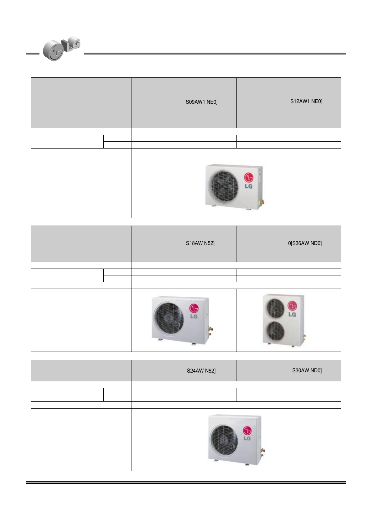
1.2 Outdoor Unit
Heat pump
AS-W096E1G0[S09AW1 NE0]
AS-W126E1G0[S12AW1 NE0]
No. of connectable indoor units Max.1
Total capacity index of connectable kW 2.64 3.52
indoor units kBtu/h 9 12
Power supply 1ø, 220-240V, 50Hz
Chassis
Heat pump
AS-W1865DH2[S18AW N52] AS-W366DGM0[S36AW ND0]
No. of connectable indoor units Max.1
Total capacity index of connectable kW 5.28 10.55
indoor units kBtu/h 18 36
Power supply 1ø, 220-240V, 50Hz
Chassis
Heat pump
AS-W2465DH2[S24AW N52]
AS-W306DGM0[S30AW ND0]
No. of connectable indoor units Max.1
Total capacity index of connectable kW 7.03 8.79
indoor units kBtu/h 24 30
Power supply 1ø, 220-240V, 50Hz
Chassis
Page 3

6 2008 Product Data
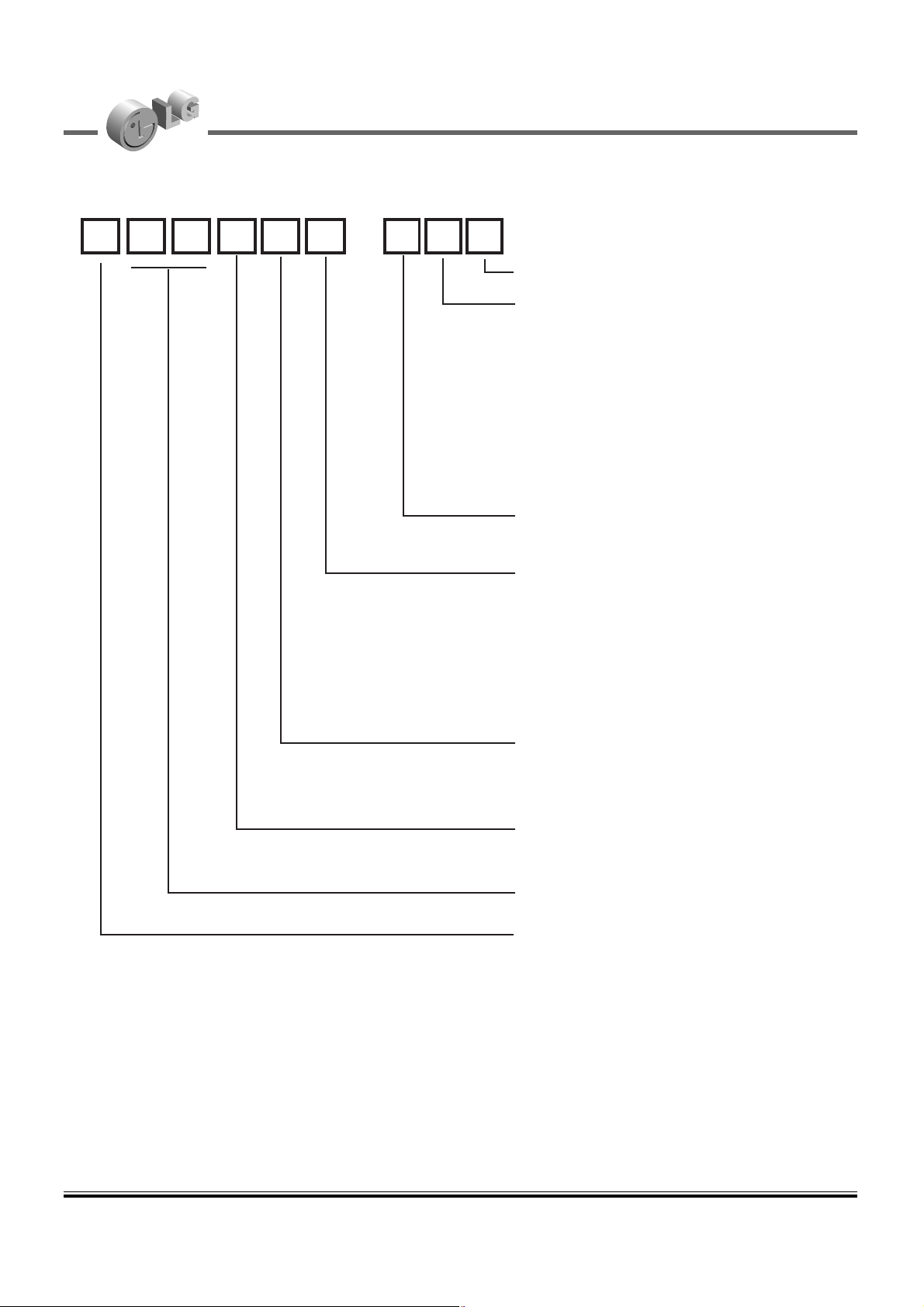
2. Nomenclature
Code Type Code of Model Meaning
1 Production Center, A~Z L: Chang-won R22
Refrigerant A: Chang-won R410A
2 Product Type A~Z S: Split Type Air Conditioner
3 Cooling/Heating/Inverter A~Z C: Cooling only
H: Heat pump
X: C/O + E/Heater
Z: H/P + E/Heater
V: AC Inverter C/O
N: AC Inverter H/P
Q: DC Inverter C/O
W: DC Inverter H/P
4, 5 Capacity 0~9 Cooling/Heating Capacity
Ex. "09" → 9,000 Btu/h
6 Electric Range 1~9 1: 115V/60Hz,
A~Z 2: 220V/60Hz
3: 208-230V/60Hz
5: 200-220V/50Hz
6: 220-240V/50Hz
7: 110V, 50/60Hz
7 Chassis A~Z Name of Chassis
8 Look A~Z ART COOL models
B : Blue C : Cherry K : Mecca 1 : The Kiss(SF chassis)
W: White D : Wood R : Mirror 2 : The Sunset(SF chassis)
M: Metal Q : Quran 3 : London Bridge(SG chassis)
General Wall Mounted models
D – Look ( Panel Type)
G – Look ( Grille Type)
Glory Look :- (a) F – Look (Blue color)
(b) H – Look (Gold)
(c) J – Look (Silver)
9, 10 Function A~Z
11 Serial No. 1~9
LG Model Development Serial No.
1 2 - 3 4 5 6 7 8 9 10
A Basic
B
Basic+4Way
C
Plasma Filter
D
Plasma Filter+4 Way
E
Tele+LCD
F
Tele+LCD+Nano plasma+4Way
G NBF F+(A/changeove)+A/clean+Low
A
H NBF F+(A/changeove)+A/clean+4way+Low
A
I
Tele+LED+4way
J
Internet
K
Plasma F+4Way+Oxygen generator
L
NBF F+(A/changeove)+A/clean
M
NBF F+(A/changeove)+A/clean+4way
N
NBF F+(A/changeove)+A/clean+PTC
P
NBF F+(A/changeove)+Autoclean+4way+PTC
Q
NBF F+(A/changeove)+A/clean+4way+Low A+PTC
R
Negative ion+A/Clean
S
(Nano)Plasma+Negative ion+A/Clean
T
4way+(Nano)Plasma F+Negative ion+A/Clean
U
Nano Plasma F+4Way+(A/changeove)+A/clean+Oxygen generator
V
4way+(Nano)Plasma F+Negative ion+A/Clean+Oxygen generator
W Dry contact
Y Basic + Low
A
A S W 0 9 6 4 G G 1
Page 4
2008 Product Data 7
2. Nomenclature
• Europe Model Number
C 0 9 A W M N 1
Development sequence
Chassis
For ART COOL type
E : SE chassis
F : SF chassis
U : SU chassis
8 : S8 chassis
For Wall mounted type
D : SD chassis
4 : S4 chassis
5 : S5 chassis
Indicator for unit type
N : Indoor
Color of the Panel
(only ART COOL Models)
M : Metal (Silver)
R : Mirror (Black)
B : Blue
D : Wood
W : White
Type of Operation
W : DC inverter Deluxe
N : DC inverter Normal
Type of Refrigerant
A : R410A
Cooling / Heating Capacity (kBtu/h)
Model Type
A : ART COOL Panel type
C : ART COOL Mirror type
S : Wall mounted type
N
Page 5

26 2008 Product Data
4. Specifications Inverter single
Inverter Single, General Wall Mounted
Note : O : Applie, X : Not applied, – : No relation
• Filters are optional in some specific areas.
• For Circuit Breaker Rating, please conform to local standards whenever necessary.
Models Unit
Cooling Capacity kW
Btu/h.
Heating Capacity kW
Btu/h.
Power Input Cooling/Heating W
Running Current Cooling/Heating A
Starting Current Cooling/Heating A
EER W/W
Btu/h.W
COP W/W
Power Supply Ø / V / Hz
Power Factor %
Air Flow Rate Indoor,Max m3/min(CFM)
Outdoor,Max m3/min(CFM)
Moisture Removal l/h.
Sound Level Indoor,H/M/L dB(A)±3
Outdoor,Max dB(A)±3
Refrigerant & Charge (at 7.5 m) g(oz)
Additional Refrigerant charge g/m(oz/ft)
Compressor Type
Model
Motor Type
Oil Type
Oil Charge cc
O.L.P. name
Fan(Indoor) Type
Motor Output W
Fan(Outdoor) Type
Motor Type
Motor Output W
Circuit Breaker* A
Power Supply Cable No.*mm
2
Power and Transmission Cable No.*mm
2
No.*mm
2
Piping Connections Liquid Side mm(in)
Gas Side mm(in)
Drain Hose(O.D/ I.D.) mm(in)
Dimensions Indoor (W*H*D) mm
inch
Outdoor (W*H*D) mm
inch
Net Weight Indoor kg(lbs)
Outdoor kg(lbs)
Operation Range Cooling(Outdoor) °C(°F)
Heating(Outdoor) °C(°F)
Max. Piping Length m(ft)
Max. Elevation Difference m(ft)
Tool Code(Chassis) Indoor + Outdoor
Functions Temperature Control
Plasma Filter
Prefilter(washable/anti-fungus)
Auto Clean
CHAOS Wind(Auto Wind)
Steps, Fan/Cool/Heat
Airflow Direction Control(up & Down)
Airflow Direction Control(left & right)
Remote Controller Type
Setting Temperature Cooling
Range Heating
Auto Operation (Micom Control)
Auto Changeover (Micom Control)
Self Diagnosis
Timer
Sleep Operation
Soft Dry Operation
Restart Delay(minute)
Deice Control(Defrost)
Hot Start
Jet Cool
Low Ambient Operation
Special Function
AS-W096E1G0[S09AW NE0] AS-W0964GG1[S09AM N41G]
0.89~2.64~3.69 0.90 ~ 2.64 ~ 3.46
3,070~9,000~12,620 3,070 ~ 9,000 ~ 11,800
0.89~3.60~5.00 0.90 ~ 3.17 ~ 3.87
3,070~12,300~17,060 3,070 ~ 10,800 ~ 13,200
650 / 870 820 / 930
3/4 3.8 / 4.3
3/4 3.8 / 4.3
4.1 3.2
13.9 11.0
4.1 3.4
1,220-240,50 1 / 220 ~ 240 / 50
94.2 93.8
8.5(300) 9.5(335)
29(1,024) 26(918)
0.6 1.3
31 / 27 / 22 / 20 32 / 28 / 25
45 45
R410A, 1,000(35.3) R410A, 630(22.2)
20(0.22) 20(0.22)
Rotary Rotary
5RS102XAA21 5RS102XAA21
Brushless DC Motor Brushless DC motor
FV50S FV50S
320 320
CS-7L 115 CS-7L 115
Cross Flow Fan Cross Flow Fan
20 20
Propeller Propeller
BLDC AC Induction
43 29
15 15
3*1.0 3*1.0
4*1.5(Including Earth) 4*1.0 (Including Earth)
6.35(1/4) 6.35(1/4)
9.52(3/8) 9.52(3/8)
21.5 /16(0.85 / 0.63) 21.5 / 16.0(0.85 / 0.63)
915*282*165 840*270*153
36.0*11.1*6.5 33.1*10.6*6.0
770*545*245 770*545*245
30.3*21.5*9.6 30.3*21.3*9.7
8(17.6) 7.5(16.5)
32(70.6) 32(70.6)
-5~43(23~109.4) -5~43(23~109.4)
-10~24(14.0~75.2) -10~24(14.0~75.2)
15(49) 15(49)
7(23) 7(23)
SE + UL S4 + UL
Thermistor Thermistor
Neo Neo
O O
O O
O O
3/4 3 / 4 / 4
Auto Auto
Auto Manual
Wireless LCD Wireless LCD
18°C ~ 30°C 18°C ~ 30°C
16°C ~ 30°C 16°C ~ 30°C
- O O
O O
24h, On/Off 24h, On/Off
O O
O O
2 2
O O
O O
O O
O(Logic) O
- -
Page 6

2008 Product Data 27
4. Specifications
Inverter single
Note : O : Applie, X : Not applied, – : No relation
• Filters are optional in some specific areas.
• For Circuit Breaker Rating, please conform to local standards whenever necessary.
Models Unit
Cooling Capacity kW
Btu/h.
Heating Capacity kW
Btu/h.
Power Input Cooling/Heating W
Running Current Cooling/Heating A
Starting Current Cooling/Heating A
EER W/W
Btu/h.W
COP W/W
Power Supply Ø / V / Hz
Power Factor %
Air Flow Rate Indoor,Max m3/min(CFM)
Outdoor,Max m3/min(CFM)
Moisture Removal l/h.
Sound Level Indoor,H/M/L dB(A)±3
Outdoor,Max dB(A)±3
Refrigerant & Charge (at 7.5 m) g(oz)
Additional Refrigerant charge g/m(oz/ft)
Compressor Type
Model
Motor Type
Oil Type
Oil Charge cc
O.L.P. name
Fan(Indoor) Type
Motor Output W
Fan(Outdoor) Type
Motor Type
Motor Output W
Circuit Breaker* A
Power Supply Cable No.*mm
2
Power and Transmission Cable No.*mm
2
No.*mm
2
Piping Connections Liquid Side mm(in)
Gas Side mm(in)
Drain Hose(O.D/ I.D.) mm(in)
Dimensions Indoor (W*H*D) mm
inch
Outdoor (W*H*D) mm
inch
Net Weight Indoor kg(lbs)
Outdoor kg(lbs)
Operation Range Cooling(Outdoor) °C(°F)
Heating(Outdoor) °C(°F)
Max. Piping Length m(ft)
Max. Elevation Difference m(ft)
Tool Code(Chassis) Indoor + Outdoor
Functions Temperature Control
Plasma Filter
Prefilter(washable/anti-fungus)
Auto Clean
CHAOS Wind(Auto Wind)
Steps, Fan/Cool/Heat
Airflow Direction Control(up & Down)
Airflow Direction Control(left & right)
Remote Controller Type
Setting Temperature Cooling
Range Heating
Auto Operation (Micom Control)
Auto Changeover (Micom Control)
Self Diagnosis
Timer
Sleep Operation
Soft Dry Operation
Restart Delay(minute)
Deice Control(Defrost)
Hot Start
Jet Cool
Low Ambient Operation
Special Function
AS-W126E1G0 [S12AW NE0] AS-W1264GG1[S12AM N41G]
0.89~3.52~4.04 0.90 ~ 3.52 ~4.04
3,070~12,000~13,800 3,070 ~ 12,000 ~ 13,800
0.89~4.57~5.48 0.90 ~ 4.00 ~ 4.86
3,070~15,600~18,720 3,070 ~ 13,650 ~ 16,600
1,090 / 1,260 1,090 / 1,170
4.8 / 5.7 5.0 / 5.3
4.8 / 5.7 5.0 / 5.3
3.2 3.2
11.0 11.0
3.63 3.4
1 / 220 ~ 240 / 50 1 / 220 ~ 240 / 50
98.7 94.8
9.5(335) 10.8(381)
29(1,024) 26(918)
1.3 1.5
37 / 27 / 22 / 20 38 / 30 / 25
45 45
R410A, 1,000(35.3) R410A, 940(33.2)
20(0.22) 20(0.22)
Rotary Rotary
5RS102XAA21 5RS102XAA21
Brushless DC Motor Brushless DC motor
FV50S FV50S
320 320
CS-7L 115 CS-7L 115
Cross Flow Fan Cross Flow Fan
20 20
Propeller Propeller
BLDC AC Induction
43 29
15 15
3*1.0 3*1.0
4*1.5(Including Earth) 4*1.0 (Including Earth)
6.35(1/4) 6.35(1/4)
9.52(3/8) 9.52(3/8)
21.5 /16(0.85 / 0.63) 21.5 / 16.0(0.85 / 0.63)
915*282*165 840*270*153
36.0*11.1*6.5 33.1*10.6*6.0
770*545*245 770*545*245
30.3*21.5*9.6 30.3*21.3*9.7
8(17.64) 7.5(16.5)
32(70.6) 32(70.6)
-5~43(23~109.4) -5~43(23~109.4)
-10~24(14.0~75.2) -10~24(14.0~75.2)
15(49) 15(49)
7(23) 7(23)
SE + UL S4 + UL
Thermistor Thermistor
Nano Neo
O O
O O
O O
3/4 3 / 4 / 4
Auto Auto
Auto Manual
Wireless LCD Wireless LCD
18°C ~ 30°C 18°C ~ 30°C
16°C ~ 30°C 16°C ~ 30°C
- O O
O O
24h, On/Off 24h, On/Off
O O
O O
2 2
O O
O O
O O
O(Logic) O
- -
Page 7

28 2008 Product Data
4. Specifications Inverter single
Note : O : Applie, X : Not applied, – : No relation
• Filters are optional in some specific areas.
• For Circuit Breaker Rating, please conform to local standards whenever necessary.
Models Unit
Cooling Capacity kW
Btu/h.
Heating Capacity kW
Btu/h.
Power Input Cooling/Heating W
Running Current Cooling/Heating A
Starting Current Cooling/Heating A
EER W/W
Btu/h.W
COP W/W
Power Supply Ø / V / Hz
Power Factor %
Air Flow Rate Indoor,Max m3/min(CFM)
Outdoor,Max m3/min(CFM)
Moisture Removal l/h.
Sound Level Indoor,H/M/L dB(A)±3
Outdoor,Max dB(A)±3
Refrigerant & Charge (at 7.5 m) g(oz)
Additional Refrigerant charge g/m(oz/ft)
Compressor Type
Model
Motor Type
Oil Type
Oil Charge cc
O.L.P. name
Fan(Indoor) Type
Motor Output W
Fan(Outdoor) Type
Motor Type
Motor Output W
Circuit Breaker* A
Power Supply Cable No.*mm
2
Power and Transmission Cable No.*mm
2
No.*mm
2
Piping Connections Liquid Side mm(in)
Gas Side mm(in)
Drain Hose(O.D/ I.D.) mm(in)
Dimensions Indoor (W*H*D) mm
inch
Outdoor (W*H*D) mm
inch
Net Weight Indoor kg(lbs)
Outdoor kg(lbs)
Operation Range Cooling(Outdoor) °C(°F)
Heating(Outdoor) °C(°F)
Max. Piping Length m(ft)
Max. Elevation Difference m(ft)
Tool Code(Chassis) Indoor + Outdoor
Functions Temperature Control
Plasma Filter
Prefilter(washable/anti-fungus)
Auto Clean
CHAOS Wind(Auto Wind)
Steps, Fan/Cool/Heat
Airflow Direction Control(up & Down)
Airflow Direction Control(left & right)
Remote Controller Type
Setting Temperature Cooling
Range Heating
Auto Operation (Micom Control)
Auto Changeover (Micom Control)
Self Diagnosis
Timer
Sleep Operation
Soft Dry Operation
Restart Delay(minute)
Deice Control(Defrost)
Hot Start
Jet Cool
Low Ambient Operation
Special Function
AS-W1865DH2 [S18AW N52] AS-W1865GG1[S18AM N51G]
1.76~5.28~5.80 1.78~5.28 ~ 5.80
6,000~18,000~19,800 6,000 ~ 18,000 ~ 19,800
1.41~6.07~6.65 1.40 ~5.80 ~ 6.65
4,800~20,700~22,700 4,800 ~ 19,790 ~ 22,700
1,640 / 1,770 1,730 / 1,800
7.3 / 8.3 8.0 / 8.3
7.3 / 8.3 8.0 / 8.3
3.2 3.1
11.0 10.4
3.4 3.2
1 / 220-240 / 50 1 / 220 ~ 240 / 50
98.8 94.0
16(565) 13.0(459)
42(1,483) 42(1,483)
2.1 2.1
42 / 39 / 36 43 / 40 / 37
55 56
R410A, 1,200(40.8) R410A 1,200(40.8)
20(0.22) 20(0.22)
E-SCROLL E-SCROLL
5CS130XCC03 5CS130XCA
Brushless DC Motor Brushless DC motor
RB68A RB68A
480 480
CS-7L N120 CS-7L N120
Cross Flow Fan Cross Flow Fan
20 24
Propeller Propeller
AC Induction AC Induction
65 85.3
15 15
3*1.5 3*1.5
4*1.5 (Including Earth) 4*1.5(Including Earth)
6.35(1/4) 6.35(1/4)
12.7(1/2) 12.7(1/2)
21.5 / 16.0(0.85 / 0.63) 21.5 / 16.0(0.85 / 0.63)
1,090*300*180 1,090*300*180
42.9*11.8*7.1 42.9*11.8*7.1
870*655*320 870*655*320
34.3*25.8*12.6 34.3*25.8*12.6
13(28.7) 13(28.7)
46(101.4) 46(101.4)
-5~43(23~109.4) -5~43(23~109.4)
-10~24(14.0~75.2) -10~24(14.0~75.2)
15(49) 15(49)
7(23) 7(23)
S5 + UE S5 + UE
Thermistor Thermistor
Nano Neo
O O
O O
O O
3 / 4 / 4 3/ 4 / 4
Auto Auto
Auto Manual
Wireless LCD Wireless LCD
18°C ~ 30°C 18°C ~ 30°C
16°C ~ 30°C 16°C ~ 30°C
- O O
O O
24hr, On/Off 24h, On/Off
O O
O O
2 2
O O
O O
O O
O(Logic) O
- -
Page 8

2008 Product Data 29
4. Specifications
Inverter single
Note : O : Applie, X : Not applied, – : No relation
• Filters are optional in some specific areas.
• For Circuit Breaker Rating, please conform to local standards whenever necessary.
Models Unit
Cooling Capacity kW
Btu/h.
Heating Capacity kW
Btu/h.
Power Input Cooling/Heating W
Running Current Cooling/Heating A
Starting Current Cooling/Heating A
EER W/W
Btu/h.W
COP W/W
Power Supply Ø / V / Hz
Power Factor %
Air Flow Rate Indoor,Max m3/min(CFM)
Outdoor,Max m3/min(CFM)
Moisture Removal l/h.
Sound Level Indoor,H/M/L dB(A)±3
Outdoor,Max dB(A)±3
Refrigerant & Charge (at 7.5 m) g(oz)
Additional Refrigerant charge g/m(oz/ft)
Compressor Type
Model
Motor Type
Oil Type
Oil Charge cc
O.L.P. name
Fan(Indoor) Type
Motor Output W
Fan(Outdoor) Type
Motor Type
Motor Output W
Circuit Breaker* A
Power Supply Cable No.*mm
2
Power and Transmission Cable No.*mm
2
No.*mm
2
Piping Connections Liquid Side mm(in)
Gas Side mm(in)
Drain Hose(O.D/ I.D.) mm(in)
Dimensions Indoor (W*H*D) mm
inch
Outdoor (W*H*D) mm
inch
Net Weight Indoor kg(lbs)
Outdoor kg(lbs)
Operation Range Cooling(Outdoor) °C(°F)
Heating(Outdoor) °C(°F)
Max. Piping Length m(ft)
Max. Elevation Difference m(ft)
Tool Code(Chassis) Indoor + Outdoor
Functions Temperature Control
Plasma Filter
Prefilter(washable/anti-fungus)
Auto Clean
CHAOS Wind(Auto Wind)
Steps, Fan/Cool/Heat
Airflow Direction Control(up & Down)
Airflow Direction Control(left & right)
Remote Controller Type
Setting Temperature Cooling
Range Heating
Auto Operation (Micom Control)
Auto Changeover (Micom Control)
Self Diagnosis
Timer
Sleep Operation
Soft Dry Operation
Restart Delay(minute)
Deice Control(Defrost)
Hot Start
Jet Cool
Low Ambient Operation
Special Function
AS-W2465DH2 [S24AW N52] AS-W306DGM0 [S30AW ND0]
3.86~7.03~7.47 3.6 ~ 8.0 ~ 8.8
13,200~24,000~25,500 12,283 ~ 27,296 ~ 30,026
3.60~8.08~8.88 5.3 ~ 9.6 ~ 10.2
12,300~27,570~30,300 18,084 ~ 32,775 ~ 34,802
2,500 / 2,880 2,650 / 3,180
11.0 / 13.0 12.0 / 14.5
11.0 / 13.0 12.0 / 14.5
2.8 3.0
9.6 10.3
2.8 3.0
1 / 220-240 / 50 1 / 220 ~ 240 / 50
98.8 97
18.0(636) 21(350)
58(966) 58(966)
3.2 3.5
44 / 41 / 37 46 / 43 / 39
56 54
R410A, 1,800(63.5) R410A, 1,800(63.3)(at 10m)
30(0.32) 30(0.32)
Rotary Rotary
5KD240XCA21 5KD240XAE21
Brushless DC Motor Brushless DC motor
FV50S FV50S
900 900
- CS-7L 115
Cross Flow Fan Cross Flow Fan
- 70
Propeller Propeller
AC Induction Brushless DC motor
83 80
30 25
3*2.5 3*2.5
4*2.5(Including Earth) 4*0.75 (Including Earth)
9.52(3/8) 6.35(1/4)
15.88(5/8) 15.88(5/8)
21.5 / 16.0 (0.85 / 0.63) 21.5 / 16.0(0.85 / 0.63)
1,090*300*178 1,209*346*205
42.9*11.8*7.1 47.6*13.6*8.1
870*808*320 870*808*320
34.25*31.5*12.6 34.3*31.8*12.6
13(28.7) 18(39.7)
60(132.3) 60(132.3)
-5~43(23~109.4) -5~43(23~109.4)
-10~24(14.0~75.2) -10~24(14.0~75.2)
30(98) 50(164)
15(49) 30(98.4)
S5 + UE1 SD + UE1
Thermistor Thermistor
Nano Neo
O O
O O
O O
3 / 4 / 3 3 / 4 / 3
Auto Auto
Auto Auto
Wireless LCD Wireless LCD
18°C ~ 30°C 18°C ~ 30°C
16°C ~ 30°C 16°C ~ 30°C
- O O
O O
24hr, On/Off 24h, On/Off
O O
O O
2 3
O O
O O
O O
O(Logic) O
- -
Page 9

30 2008 Product Data
4. Specifications Inverter single
Models Unit
Cooling Capacity kW
Btu/h.
Heating Capacity kW
Btu/h.
Power Input Cooling/Heating W
Running Current Cooling/Heating A
Starting Current Cooling/Heating A
EER W/W
Btu/h.W
COP W/W
Power Supply Ø / V / Hz
Power Factor %
Air Flow Rate Indoor,Max m3/min(CFM)
Outdoor,Max m3/min(CFM)
Moisture Removal l/h.
Sound Level Indoor,H/M/L dB(A)±3
Outdoor,Max dB(A)±3
Refrigerant & Charge (at 7.5 m) g(oz)
Additional Refrigerant charge g/m(oz/ft)
Compressor Type
Model
Motor Type
Oil Type
Oil Charge cc
O.L.P. name
Fan(Indoor) Type
Motor Output W
Fan(Outdoor) Type
Motor Type
Motor Output W
Circuit Breaker* A
Power Supply Cable No.*mm
2
Power and Transmission Cable No.*mm
2
No.*mm
2
Piping Connections Liquid Side mm(in)
Gas Side mm(in)
Drain Hose O.D / I.D mm(in)
Dimensions Indoor (W*H*D) mm
inch
Outdoor (W*H*D) mm
inch
Net Weight Indoor kg(lbs)
Outdoor kg(lbs)
Operation Range Cooling(Outdoor) °C(°F)
Heating(Outdoor) °C(°F)
Max. Piping Length m(ft)
Max. Elevation Difference m(ft)
Tool Code(Chassis) Indoor + Outdoor
Functions Temperature Control
Plasma Filter
Prefilter(washable/anti-fungus)
Auto Clean
CHAOS Wind(Auto Wind)
Steps, Fan/Cool/Heat
Airflow Direction Control(up & Down)
Airflow Direction Control(left & right)
Remote Controller Type
Setting Temperature Cooling
Range Heating
Auto Operation (Micom Control)
Auto Changeover (Micom Control)
Self Diagnosis
Timer
Sleep Operation
Soft Dry Operation
Restart Delay(minute)
Deice Control(Defrost)
Hot Start
Jet Cool
Low Ambient Operation
Special Function
AS-W366DGM0 [S36AW ND0]
4.0 ~ 9.0 ~ 9.8
13,648 ~ 30,708 ~ 33,438
5.6 ~ 10.4 ~ 11.0
19,107 ~ 35,485 ~ 37,532
2,980 / 3,450
13.6 / 16.5
13.6 / 16.5
3.2
10.3
3.0
1 / 220 ~ 240 / 50
97
25(416)
68(1133)
4.2
47 / 44 / 41
58
R410A, 2,200(77.6)
35(0.38)
Rotary
5JD420XAD22
Brushless DC motor
FV50S
1,300
CS-7L 115
Cross Flow Fan
75
Propeller
Brushless DC motor
100
25
3*2.5
4*0.75 (Including Earth)
6.35(1/4)
15.88(5/8)
21.5 / 16.0(0.85 / 0.63)
1,209*346*205
47.6*13.6*8.1
870*1,060*320
34.3*41.7*12.6
19(41.9)
75(165.3)
-10 ~ 43 (14 ~ 109.4)
-15 ~ 24(5 ~ 75.2)
50(164)
30(98.4)
SD + UE2
Thermistor
Neo
O
O
O
3 / 4 / 3
Auto
Auto
Wireless LCD
18°C ~ 30°C
16°C ~ 30°C
O
O
24h, On/Off
O
O
3
O
O
O
O
-
Note : O : Applie, X : Not applied, – : No relation
• Filters are optional in some specific areas.
• For Circuit Breaker Rating, please conform to local standards whenever necessary.
Page 10
28 2007 Product Data
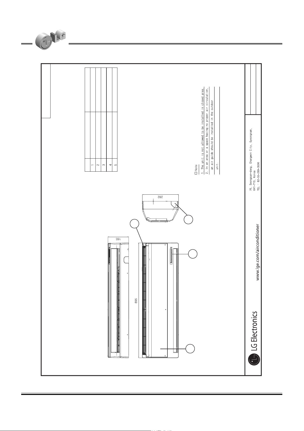
5. Dimensional Drawings Indoor Units
TOOL CODE : SE
General Wall Mounted
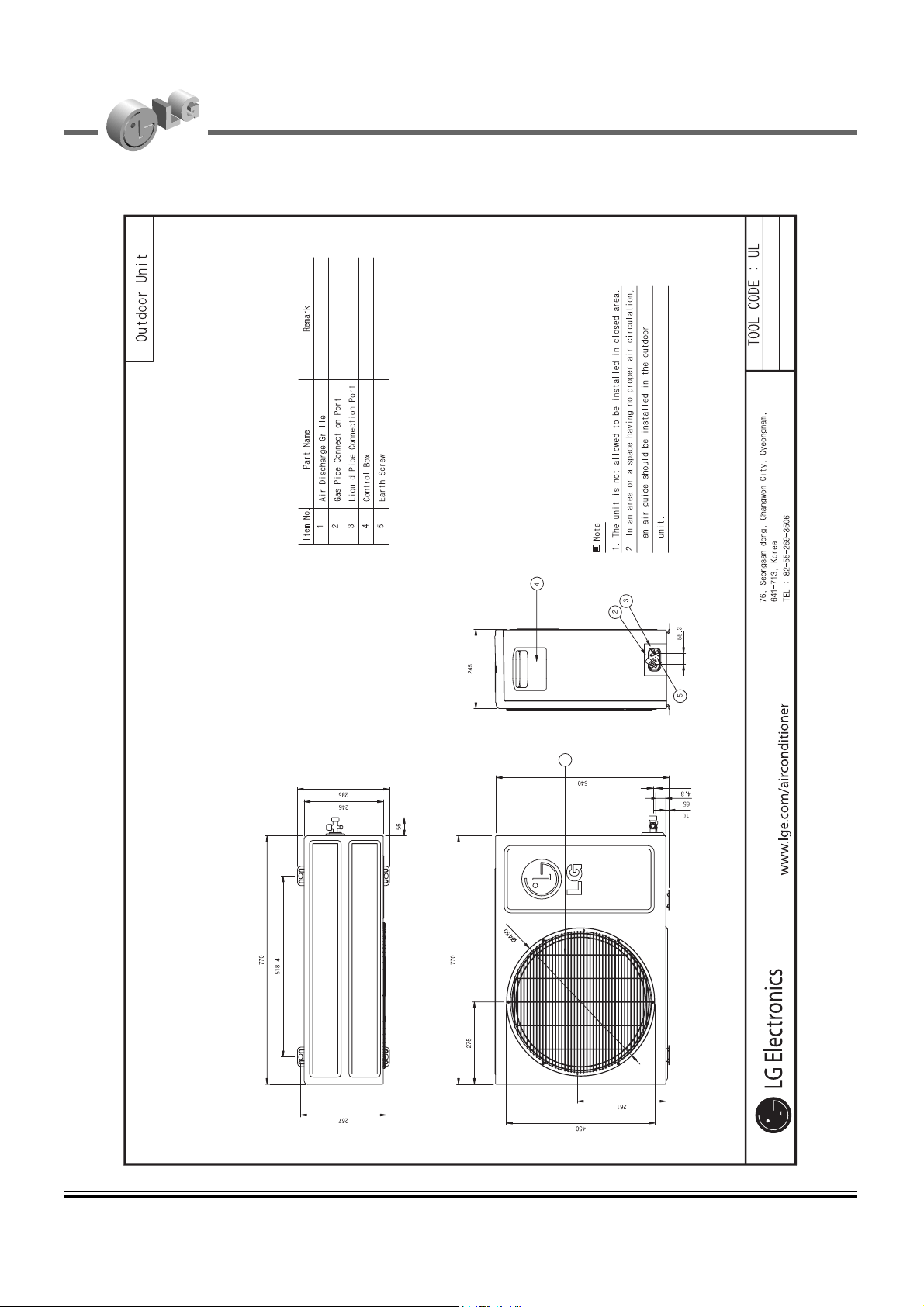
Part name
Front Panel
Display & signal receiver
Knockout hole
Air suction grille
Item No.
Remark
1
2
3
4
S09AW & S12AW-NE0
Page 11
34 2008 Product Data
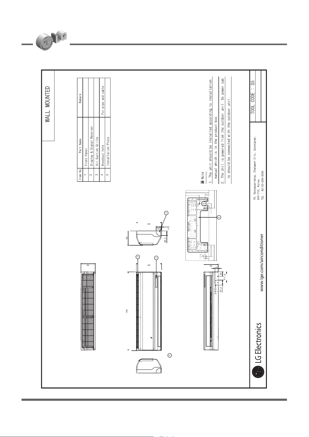
5. Dimensional drawings Indoor units
45
140
Ø70
188
926
65
221
45
296
175
Ø
70
S18AW & S24AW-N52
Page 12

2008 Product Data 35
5. Dimensional drawings
Indoor units
S30AW & S36AW-ND0
Page 13
2008 Product Data 39
5. Dimensional drawings
Outdoor units
1
5.2 Outdoor Units
S09AW & S12AW-UE0
Page 14
40 2008 Product Data
5. Dimensional drawings Outdoor units
1
S18AW-U52
Page 15
2008 Product Data 41
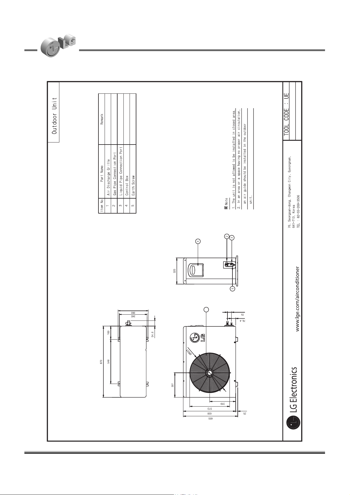
5. Dimensional drawings
Outdoor units
76.4
79
TOOL CODE : UE1
870
06
1
6
45
340
360
54 .6
301
319
ÿ
531
808
25
320
4
2
3
5
1
S24AW-U52
S30AW-UD0
Page 16

42 2008 Product Data
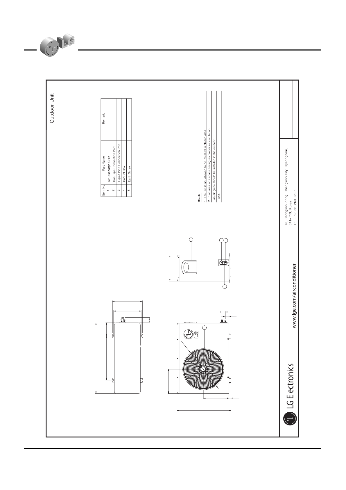
5. Dimensional drawings Outdoor units
5
1
320
492261
546
870
10
162
2
3
4
55
360
34010
301
460
1038
1060
75
80
TOOL CODE : UE2
320
Part Name Remark
S36AW-UD0
Page 17

2008 Product Data 43
6. Wiring diagrams
Indoor Unit
6.1 Indoor units
Models:
AS-W096E1G0 [S09AW1-NE0], AS-W126E1G0 [S12AW1-NE0], AS-W2465DH2 [S24AW-N52]
Page 18

46 2008 Product Data
6. Wiring diagrams Indoor Unit
Models: AS-W1865DH2 [S18AW-N52]
CN_TH1
CN_TH2
CN_HVB(BL) CN_DISP2(BL)CN_U/D(WH)CN_L/R(BL)
CN_DISP1(WH)
CN_MOTOR1
Page 19

2008 Product Data 49
6. Wiring diagrams Indoor Unit
Models:AS-W306DGM0 [S30AW-ND0], AS-W366DGM0 [A36AW-ND0]
CN-MOTOR1
CN-L/R(BL)
CN-TH1
CN-DISP1(WH)
CN-DISP2(BL)
CN-HVB
CN-U/D(WH)
CN-12V
CN-TH2
Page 20

50 2008 Product Data
6. Wiring diagrams Outdoor units
6.2 Outdoor units
Models: AS-W096E1G0 [S09AW1-NE0], AS-W126E1G0 [S12AW1-NE0]
Page 21

52 2008 Product Data
Models: AS-W1865DH2 [S18AW-N52]
6. Wiring diagrams Outdoor units
CN_FAN(A)
CN_4WAY
CN_COIL1
CN_COIL2
CN_TH2
(AIR/PIPE)
CN_TH3
(SUC/DIS_I)
CN_LEV1
CN_COM
Page 22

54 2008 Product Data
6. Wiring diagrams Outdoor units
Models: AS-W2465DH2 [S24AW-N52]
Page 23

2008 Product Data 55
6. Wiring diagrams
Outdoor units
Models: AS-W306DGM0 [S30AW-ND0]
CN-PFC-IN
CN-PFC-OUT
CN_TH3
CN-TH2
CN-MOTOR1
CN 4WAY
CN_H/P
CN_LEV1
CN_COM
Page 24

56 2008 Product Data
6. Wiring diagrams Outdoor units
Models: AS-W366DGM0 [S36AW-ND0]
CN-PFC-IN
CN-PFC-OUT
CN_TH3
CN-TH2
CN-MOTOR1
CN-MOTOR2
CN 4WAY
CN_H/P
CN_LEV1
CN_COM
Page 25

58 2008 Product Data
7. Refrigerant cycle diagram
Model no:
AS-W096E1G0 [S09AW1-NE0], AS-W126E1G0 [S12AW1-NE0]
Indoor Unit Outdoor Unit
Heat
Exchanger
(Evaporator)
Heat
Exchanger
(Condenser)
Compressor
Accumulator
Gas Side
3-Way Valve
2-Way Valve
Liquid Side
Cooling
Heating
Th1
Th2
Th4
Th5
Th3
LOC. Description PCB Connector
Th1 Thermistor for indoor air temperature
CN-TH1(INDOOR)
Th2 Thermistor for evaporating temperature
CN-TH1(INDOOR)
Th3 Thermistor for discharge pipe temperature
CN-D_PIPE(OUTDOOR)
Th4 Thermistor for condensing temperature CN-TH1(OUTDOOR)
Th5 Thermistor for outdoor air temperature
CN-TH1(OUTDOOR)
EEV
Page 26

2008 Product Data 59
7. Refrigerant cycle diagram
Model no: AS-W1865DH2 [S18AW-N52]
Indoor Unit Outdoor Unit
Heat
Exchanger
(Evaporator)
Heat
Exchanger
(Condenser)
EEV
Compressor
Gas Side
3-Way Valve
2-Way Valve
Liquid Side
Cooling
Heating
Reversing Valve
Th1
Th2
Th3
Th5
Th4
Th6
Th7
LOC. Description PCB Connector
Th1 Thermistor for indoor air temperature
CN_TH1(INDOOR)
Th2 Thermister for indoor pipe(in) temperature
Th3 Thermister for indoor pipe(out) temperature CN_TH2(INDOOR)
Th4 Thermistor for outdoor air temperature
CN_TH2(OUTDOOR)
Th5 Thermister for outdoor pipe temperature
Th6 Thermistor for discharge pipe temperature
CN_TH3(OUTDOOR)
Th7 Thermistor for suction pipe temperature
Page 27

60 2008 Product Data
7. Refrigerant cycle diagram
Model no: AS-W2465DH2 [S24AW-N52]
Indoor Unit Outdoor Unit
Heat
Exchanger
(Evaporator)
Heat
Exchanger
(Condenser)
EEV
Compressor
Gas Side
3-Way Valve
3-Way Valve
Liquid Side
Cooling
Heating
Reversing Valve
Th1
Th2
Th3
Th5
Th4
Th6
Th7
LOC. Description PCB Connector
Th1 Thermistor for indoor air temperature
CN_TH1(INDOOR)
Th2 Thermister for indoor pipe(in) temperature
Th3 Thermister for indoor pipe(out) temperature CN_TH2(INDOOR)
Th4 Thermistor for outdoor air temperature
CN_TH2(OUTDOOR)
Th5 Thermister for outdoor pipe temperature
Th6 Thermistor for discharge pipe temperature
CN_TH3(OUTDOOR)
Th7 Thermistor for suction pipe temperature
Page 28

2008 Product Data 61
7. Refrigerant cycle diagram
Model no: AS-W306DGM0 [S30AW-ND0], AS-W366DGM0 [S36AW-ND0]
High
Pressure
S/W
Th7
Inverter
Compressor
Reversing
Valve
Th6
Indoor Unit Outdoor Unit
Heat
Exchanger
(Evaporator)
Heat
Exchanger
(Condenser)
EEV
Accumulator
Gas Side
3-Way Valve
3-Way Valve
Liquid Side
Cooling
Heating
Th1
Th3
Th2
Th4
Th5
LOC. Description PCB Connector
Th1 Thermister for indoor air temperature
CN_TH1(INDOOR)
Th2 Thermister for indoor pipe(in) temperature
Th3 Thermister for indoor pipe(out) temperature CN-TH2(INDOOR)
Th4 Thermister for outdoor pipe temperature
CN_TH2(OUTDOOR)
Th5 Thermister for outdoor air temperature
Th6 Thermister for outdoor discharge pipe temperature(Inverter)
CN_TH3(OUTDOOR)
Th7 Thermister for outdoor suction pipe temperature(Inverter)
Page 29

2008 Product Data 65
Symbol Notes
AFR : Air flow rate [m3/min] 1. All capacities are net, evaporator fan motor heat is deducted.
DB : Dry bulb temperature [°C] 2. Indicates nominal maximum capacity.
WB : Wet bulb temperature [°C] 3. Direct interpolation is permissible. Do not extrapolate
TC : Total capacity [kW] 4. Capacities are based on the following conditions:
SHC : Sensible capacity [kW] - Interconnecting Piping Length 7.5m
PI : Power Input [kW] - Level Difference of Zero.
(Comp.+ indoor fan motor+outdoor fan motor)
8. Capacity tables Cooling
AS-W126E1G0 [S12AW1-NE0]
°CWB °CDB TC SHC PI TC SHC PI TC SHC PI
14.0 20.0
16.0 22.0
18.0 25.0
19.0 27.0
22.0 30.0
24.0 32.0
2.85 2.22 0.71 2.79 2.21 0.85 2.66 2.14 0.99
3.33 2.53 0.73 3.26 2.50 0.86 3.10 2.43 1.00
3.71 2.75 0.74 3.63 2.72 0.87 3.46 2.63 1.02
3.89 2.84 0.75 3.80 2.81 0.89 3.63 2.72 1.03
4.27 3.01 0.76 4.17 2.97 0.90 3.98 2.87 1.05
4.43 3.06 0.77 4.33 3.02 0.91 4.13 2.92 1.06
Outdoor Air Temperature : °CDB
20 25 32
Indoor Air
Temperature
°CWB °CDB TC SHC PI TC SHC PI TC SHC PI
14.0 20.0
16.0 22.0
18.0 25.0
19.0 27.0
22.0 30.0
24.0 32.0
2.58 2.10 1.04 2.49 2.05 1.11 2.43 2.03 1.14
3.01 2.38 1.06 2.90 2.32 1.12 2.83 2.28 1.16
3.36 2.57 1.07 3.24 2.51 1.14 3.16 2.47 1.18
3.52 2.66 1.09 3.39 2.59 1.16 3.31 2.55 1.20
3.86 2.81 1.10 3.72 2.73 1.17 3.63 2.68 1.21
4.01 2.84 1.12 3.86 2.76 1.19 3.77 2.71 1.23
Outdoor Air Temperature : °CDB
35 40 43
Indoor Air
Temperature
Page 30

2008 Product Data 67
AS-W1865DH2 [S18AW-N52]
°CWB °CDB TC SHC PI TC SHC PI TC SHC PI
14.0 20.0
16.0 22.0
18.0 25.0
19.0 27.0
22.0 30.0
24.0 32.0
5.18 4.27 0.91 4.95 4.13 0.95 4.65 3.96 1.27
5.50 4.32 1.23 5.27 4.19 1.24 4.97 4.04 1.50
5.81 4.36 1.33 5.59 4.24 1.34 5.28 4.10 1.57
5.97 4.40 1.34 5.75 4.28 1.36 5.44 4.14 1.59
6.45 4.49 1.34 6.22 4.38 1.38 5.91 4.25 1.63
6.77 4.57 1.34 6.54 4.47 1.39 6.23 4.35 1.66
Outdoor Air Temperature : °CDB
20 25 32
Indoor Air
Temperature
°CWB °CDB TC SHC PI TC SHC PI TC SHC PI
14.0 20.0
16.0 22.0
18.0 25.0
19.0 27.0
22.0 30.0
24.0 32.0
4.51 3.83 1.42 4.31 3.71 1.56 4.19 3.58 1.53
4.82 3.91 1.61 4.62 3.80 1.68 4.51 3.68 1.60
5.14 3.97 1.64 4.94 3.87 1.70 4.82 3.75 1.59
5.28 4.01 1.64 5.10 3.92 1.71 4.98 3.80 1.59
5.76 4.13 1.72 5.57 4.05 1.73 5.45 3.93 1.61
6.08 4.23 1.75 5.88 4.15 1.77 5.76 4.03 1.64
Outdoor Air Temperature : °CDB
35 40 43
Indoor Air
Temperature
8. Capacity tables
Cooling
Symbol Notes
AFR : Air flow rate [m3/min] 1. All capacities are net, evaporator fan motor heat is deducted.
DB : Dry bulb temperature [°C] 2. Indicates nominal maximum capacity.
WB : Wet bulb temperature [°C] 3. Direct interpolation is permissible. Do not extrapolate
TC : Total capacity [kW] 4. Capacities are based on the following conditions:
SHC : Sensible capacity [kW] - Interconnecting Piping Length 7.5m
PI : Power Input [kW] - Level Difference of Zero.
(Comp.+ indoor fan motor+outdoor fan motor)
Page 31

2008 Product Data 69
AS-W2465DH2 [S24AW-N52]
°CWB °CDB TC SHC PI TC SHC PI TC SHC PI
14.0 20.0
16.0 22.0
18.0 25.0
19.0 27.0
22.0 30.0
24.0 32.0
5.70 4.45 1.64 5.58 4.41 1.94 5.32 4.29 2.26
6.66 5.05 1.66 6.52 5.00 1.97 6.21 4.86 2.30
7.43 5.50 1.69 7.27 5.43 2.00 6.93 5.27 2.33
7.77 5.68 1.72 7.61 5.62 2.04 7.25 5.44 2.37
8.53 6.03 1.74 8.35 5.95 2.06 7.96 5.75 2.40
8.85 6.13 1.76 8.67 6.04 2.09 8.26 5.83 2.44
Outdoor Air Temperature : °CDB
20 25 32
Indoor Air
Temperature
°CWB °CDB TC SHC PI TC SHC PI TC SHC PI
14.0 20.0
16.0 22.0
18.0 25.0
19.0 27.0
22.0 30.0
24.0 32.0
5.16 4.20 2.38 4.97 4.11 2.54 4.86 4.05 2.62
6.02 4.75 2.42 5.80 4.64 2.58 5.66 4.57 2.66
6.72 5.15 2.46 6.47 5.02 2.61 6.32 4.94 2.70
7.03 5.31 2.50 6.77 5.18 2.66 6.62 5.09 2.75
7.72 5.61 2.53 7.43 5.46 2.69 7.26 5.36 2.78
8.01 5.69 2.57 7.71 5.53 2.73 7.53 5.42 2.82
Outdoor Air Temperature : °CDB
35 40 43
Indoor Air
Temperature
8. Capacity tables
Cooling
Symbol Notes
AFR : Air flow rate [m
3
/min] 1. All capacities are net, evaporator fan motor heat is deducted.
DB : Dry bulb temperature [°C] 2. Indicates nominal maximum capacity.
WB : Wet bulb temperature [°C] 3. Direct interpolation is permissible. Do not extrapolate
TC : Total capacity [kW] 4. Capacities are based on the following conditions:
SHC : Sensible capacity [kW] - Interconnecting Piping Length 7.5m
PI : Power Input [kW] - Level Difference of Zero.
(Comp.+ indoor fan motor+outdoor fan motor)
Page 32

70 2008 Product Data
Symbol Notes
AFR : Air flow rate [m3/min] 1. All capacities are net, evaporator fan motor heat is deducted.
DB : Dry bulb temperature [°C] 2. Indicates nominal maximum capacity.
WB : Wet bulb temperature [°C] 3. Direct interpolation is permissible. Do not extrapolate
TC : Total capacity [kW] 4. Capacities are based on the following conditions:
SHC : Sensible capacity [kW] - Interconnecting Piping Length 7.5m
PI : Power Input [kW] - Level Difference of Zero.
(Comp.+ indoor fan motor+outdoor fan motor)
8. Capacity tables Cooling
AS-W306DGM0 [S30AW-ND0]
°CWB °CDB TC SHC PI TC SHC PI TC SHC PI
14.0 20.0
16.0 22.0
18.0 25.0
19.0 27.0
22.0 30.0
24.0 32.0
7.84 6.90 1.46 7.50 6.68 1.53 7.04 6.41 2.05
8.33 6.99 1.98 7.98 6.78 2.00 7.52 6.53 2.42
8.81 7.05 2.15 8.46 6.85 2.16 8.00 6.62 2.54
9.05 7.12 2.17 8.70 6.92 2.19 8.24 6.70 2.57
9.78 7.26 2.17 9.43 7.08 2.23 8.96 6.88 2.63
10.26 7.39 2.16 9.91 7.22 2.25 9.44 7.03 2.68
Outdoor Air Temperature : °CDB
20 25 32
Indoor Air
Temperature
°CWB °CDB TC SHC PI TC SHC PI TC SHC PI
14.0 20.0
16.0 22.0
18.0 25.0
19.0 27.0
22.0 30.0
24.0 32.0
6.83 6.19 2.29 6.53 6.00 2.52 6.35 5.79 2.46
7.31 6.32 2.60 7.01 6.15 2.71 6.83 5.94 2.58
7.78 6.42 2.65 7.48 6.26 2.75 7.30 6.06 2.58
8.00 6.48 2.65 7.72 6.34 2.76 7.54 6.14 2.57
8.73 6.68 2.78 8.43 6.54 2.80 8.25 6.35 2.60
9.21 6.84 2.83 8.91 6.71 2.86 8.73 6.52 2.65
Outdoor Air Temperature : °CDB
35 40 43
Indoor Air
Temperature
Page 33

2008 Product Data 71
Symbol Notes
AFR : Air flow rate [m3/min] 1. All capacities are net, evaporator fan motor heat is deducted.
DB : Dry bulb temperature [°C] 2. Indicates nominal maximum capacity.
WB : Wet bulb temperature [°C] 3. Direct interpolation is permissible. Do not extrapolate
TC : Total capacity [kW] 4. Capacities are based on the following conditions:
SHC : Sensible capacity [kW] - Interconnecting Piping Length 7.5m
PI : Power Input [kW] - Level Difference of Zero.
(Comp.+ indoor fan motor+outdoor fan motor)
8. Capacity tables Cooling
AS-W366DGM0 [S36AW-ND0]
°CWB °CDB TC SHC PI TC SHC PI TC SHC PI
14.0 20.0
16.0 22.0
18.0 25.0
19.0 27.0
22.0 30.0
24.0 32.0
8.82 7.29 1.65 8.44 7.05 1.72 7.93 6.77 2.31
9.37 7.38 2.23 8.98 7.16 2.25 8.46 6.89 2.72
9.91 7.44 2.41 9.52 7.24 2.43 9.00 6.99 2.86
10.18 7.51 2.44 9.79 7.31 2.46 9.27 7.07 2.89
11.00 7.66 2.44 10.60 7.47 2.50 10.08 7.26 2.96
11.54 7.80 2.43 11.14 7.62 2.53 10.62 7.42 3.01
Outdoor Air Temperature : °CDB
20 25 32
Indoor Air
Temperature
°CWB °CDB TC SHC PI TC SHC PI TC SHC PI
14.0 20.0
16.0 22.0
18.0 25.0
19.0 27.0
22.0 30.0
24.0 32.0
7.68 6.54 2.58 7.35 6.34 2.83 7.14 6.12 2.77
8.22 6.67 2.92 7.88 6.49 3.05 7.68 6.27 2.90
8.75 6.78 2.98 8.42 6.61 3.09 8.22 6.40 2.90
9.00 6.84 2.98 8.69 6.69 3.10 8.48 6.49 2.89
9.83 7.05 3.12 9.49 6.90 3.15 9.29 6.70 2.92
10.36 7.22 3.19 10.02 7.08 3.22 9.82 6.88 2.98
Outdoor Air Temperature : °CDB
35 40 43
Indoor Air
Temperature
Page 34

2008 Product Data 73
8. Capacity tables Heating
Symbol Notes
AFR : Air flow rate [m3/min] 1. All capacities are net, evaporator fan motor heat is deducted.
DB : Dry bulb temperature [°C] 2. Indicates nominal maximum capacity.
WB : Wet bulb temperature [°C] 3. Direct interpolation is permissible. Do not extrapolate
TC : Total capacity [kW] 4. Capacities are based on the following conditions:
SHC : Sensible capacity [kW] - Interconnecting Piping Length 7.5m
PI : Power Input [kW] - Level Difference of Zero.
(Comp.+ indoor fan motor+outdoor fan motor) - Outdoor air : 85%RH. However, the condition on nominal capacity
is 7°CDB/6°CWB
AS-W126E1G0 [S12AW1-NE0]
°CDB TC PI TC PI TC PI TC PI TC PI TC PI TC PI
16.0
18.0
20.0
21.0
22.0
24.0
3.44 1.03 3.62 1.00 3.92 1.05 4.19 1.13 4.65 1.21 4.91 1.25 5.33 1.34
3.40 1.04 3.61 1.03 3.92 1.08 4.18 1.16 4.62 1.23 4.85 1.28 5.31 1.35
3.38 1.06 3.61 1.05 3.93 1.11 4.17 1.19 4.57 1.26 4.82 1.30 5.32 1.36
3.37 1.07 3.61 1.07 3.93 1.13 4.16 1.20 4.54 1.27 4.82 1.31 5.29 1.36
3.36 1.08 3.61 1.08 3.92 1.14 4.15 1.22 4.51 1.28 4.81 1.31 5.24 1.36
3.32 1.11 3.57 1.11 3.88 1.17 4.12 1.25 4.47 1.30 4.73 1.33 5.18 1.37
Outdoor Air Temperature : °CWB
-15 -10 -5 0 6 10 15
Indoor Air
Temperature (°C)
Page 35

74 2008 Product Data
AS-W1865DH2 [S18AW-N52]
Symbol Notes
AFR : Air flow rate [m3/min] 1. All capacities are net, evaporator fan motor heat is deducted.
DB : Dry bulb temperature [°C] 2. Indicates nominal maximum capacity.
WB : Wet bulb temperature [°C] 3. Direct interpolation is permissible. Do not extrapolate
TC : Total capacity [kW] 4. Capacities are based on the following conditions:
SHC : Sensible capacity [kW] - Interconnecting Piping Length 7.5m
PI : Power Input [kW] - Level Difference of Zero.
(Comp.+ indoor fan motor+outdoor fan motor) - Outdoor air : 85%RH. However, the condition on nominal capacity
is 7°CDB/6°CWB
8. Capacity tables Heating
°CDB TC PI TC PI TC PI TC PI TC PI TC PI TC PI
16.0
18.0
20.0
21.0
22.0
24.0
4.56 1.44 4.80 1.41 5.20 1.47 5.56 1.58 6.17 1.69 6.52 1.76 7.08 1.88
4.52 1.46 4.79 1.44 5.21 1.52 5.56 1.63 6.13 1.73 6.44 1.80 7.05 1.90
4.49 1.49 4.79 1.48 5.21 1.56 5.54 1.67 6.07 1.77 6.40 1.82 7.07 1.91
4.48 1.51 4.79 1.50 5.21 1.58 5.53 1.69 6.03 1.79 6.40 1.84 7.02 1.91
4.47 1.52 4.79 1.52 5.21 1.60 5.51 1.71 5.99 1.80 6.39 1.85 6.96 1.91
4.42 1.56 4.75 1.57 5.15 1.65 5.47 1.75 5.94 1.83 6.28 1.86 6.88 1.93
Outdoor Air Temperature : °CWB
-15 -10 -5 0 6 10 15
Indoor Air
Temperature (°C)
Page 36

2008 Product Data 75
AS-W366DGM0 [S36AW-ND0]
°CDB TC PI TC PI TC PI TC PI TC PI TC PI TC PI
16.0
18.0
20.0
21.0
22.0
24.0
7.82 2.81 8.23 2.74 8.92 2.87 9.52 3.09 10.57 3.30 11.17 3.44 12.12 3.66
7.74 2.85 8.21 2.81 8.93 2.96 9.52 3.17 10.50 3.38 11.03 3.50 12.09 3.70
7.69 2.91 8.21 2.89 8.93 3.04 9.50 3.26 10.40 3.45 10.96 3.56 12.11 3.72
7.67 2.94 8.21 2.92 8.93 3.08 9.47 3.30 10.33 3.48 10.96 3.58 12.03 3.73
7.66 2.97 8.21 2.96 8.93 3.13 9.45 3.34 10.26 3.51 10.94 3.60 11.93 3.73
7.56 3.04 8.13 3.05 8.82 3.21 9.37 3.42 10.18 3.57 10.76 3.63 11.79 3.76
Outdoor Air Temperature : °CWB
-15 -10 -5 0 6 10 15
Indoor Air
Temperature (°C)
Symbol Notes
AFR : Air flow rate [m3/min] 1. All capacities are net, evaporator fan motor heat is deducted.
DB : Dry bulb temperature [°C] 2. Indicates nominal maximum capacity.
WB : Wet bulb temperature [°C] 3. Direct interpolation is permissible. Do not extrapolate
TC : Total capacity [kW] 4. Capacities are based on the following conditions:
SHC : Sensible capacity [kW] - Interconnecting Piping Length 7.5m
PI : Power Input [kW] - Level Difference of Zero.
(Comp.+ indoor fan motor+outdoor fan motor) - Outdoor air : 85%RH. However, the condition on nominal capacity
is 7°CDB/6°CWB
8. Capacity tables Heating
AS-W2465DH2 [S24AW-N52]
AS-W306DGM0 [S30AW-ND0]
°CDB TC PI TC PI TC PI TC PI TC PI TC PI TC PI
16.0
18.0
20.0
21.0
22.0
24.0
6.08 2.35 6.39 2.29 6.93 2.40 7.40 2.58 8.21 2.76 8.68 2.87 9.42 3.06
6.01 2.38 6.38 2.35 6.94 2.47 7.40 2.65 8.16 2.82 8.57 2.92 9.39 3.09
5.97 2.43 6.38 2.41 6.94 2.54 7.38 2.72 8.08 2.88 8.51 2.97 9.41 3.11
5.96 2.45 6.38 2.44 6.94 2.57 7.36 2.75 8.03 2.91 8.51 2.99 9.34 3.11
5.95 2.48 6.38 2.48 6.94 2.61 7.34 2.79 7.97 2.93 8.50 3.00 9.27 3.11
5.88 2.54 6.32 2.55 6.85 2.68 7.28 2.86 7.91 2.98 8.36 3.03 9.16 3.14
Outdoor Air Temperature : °CWB
-15 -10 -5 0 6 10 15
Indoor Air
Temperature (°C)
°CDB TC PI TC PI TC PI TC PI TC PI TC PI TC PI
16.0
18.0
20.0
21.0
22.0
24.0
7.22 2.65 7.59 2.59 8.23 2.71 8.79 2.91 9.76 3.11 10.31 3.24 11.19 3.45
7.15 2.69 7.58 2.65 8.24 2.78 8.79 2.99 9.69 3.18 10.18 3.30 11.16 3.49
7.10 2.74 7.58 2.72 8.25 2.86 8.76 3.07 9.60 3.25 10.12 3.35 11.18 3.51
7.08 2.77 7.58 2.75 8.25 2.90 8.75 3.11 9.54 3.28 10.11 3.37 11.10 3.51
7.07 2.80 7.58 2.79 8.24 2.94 8.72 3.15 9.47 3.31 10.10 3.39 11.01 3.51
6.98 2.86 7.51 2.87 8.14 3.03 8.65 3.22 9.39 3.36 9.93 3.42 10.88 3.54
Outdoor Air Temperature : °CWB
-15 -10 -5 0 6 10 15
Indoor Air
Temperature (°C)
Page 37

76 2008 Product Data
9. Capacity coefficient factor
100
90
80
70
7.5 15 5030
30k/36k
24k
9k/12k/18k
Capacity(%)
Total Pipe Length(m)
100
90
80
70
7.5 15 5030
9k/12k/18k
24k
30k/36k
Capacity(%)
Total Pipe Length(m)
Cooling
Heating
Page 38

2008 Product Data 77
9. Capacity coefficient factor
Notes
❈ Equivalent pipe length = actual pipe length + number of band x 0.3
❈ Additional Refrigerant Charge
Example: For Model No. AS-W126ADR0 having 15m pipe length, additional refrigerant to be charged is
(15-7) x 20 = 160g
* Refer to the specification for the maximum pipe length of each model.
* 18k S5/S8 Chassis total piping length is 15m.
AS-W096ADR0 15 7 20(0.22)
AS-W0964GG1 15 7 20(0.22)
AS-W096E*H2 15 7 20(0.22)
AS-W096E1G0 15 7 20(0.22)
AS-W096F*G2 15 7 20(0.22)
AS-W096F1G2 15 7 20(0.22)
AS-W096U*H1 15 7 20(0.22)
AS-W126ADR0 15 7 20(0.22)
AS-W1264GG1 15 7 20(0.22)
AS-W126E*H2 15 7 20(0.22)
AS-W126E1G0 15 7 20(0.22)
AS-W126F*G2 15 7 20(0.22)
AS-W126F1G2 15 7 20(0.22)
AS-W126U*H1 15 7 20(0.22)
AS-W1863*H3 15 7 20(0.22)
AS-W1865DH2 15 7 20(0.22)
AS-W1865GG1 15 7 20(0.22)
AS-W1868*H1 15 7 20(0.22)
AS-W2463*H3 30 15 30(0.32)
AS-W2465DH2 30 15 30(0.32)
AS-W2468*H1 30 15 30(0.32)
AS-W306DGM0 50 30 30(0.32)
AS-W366DGM0 50 30 35(0.37)
Model No.
Max. Pipe
Length(m)
Max. Elevation
(m)
Additional
Refrigerant[g/m(oz/ft)]
CAUTION:
•
Capacity is based on
standard length and
maximum allowance
length is on the basis
of reliability.
• Oil trap should be
installed every 5~7
meters.
Outdoor unit
Indoor unit
A
B
Outdoor unit
Indoor unit
A
B
A
Oil trap
Outdoor unit
Indoor unit
B
If piping length is more than 5m
Page 39

78 2008 Product Data
10. Operation range
Cooling
-15
-10
16
30
Operative
Continuous
operation
24
Warming up
Operation
Outdoor
Unit
[°C DB]
Indoor Unit [°C DB]
Heating
Indoor Unit [°C DB]
Outdoor
Unit
[°C DB]
-10
43
46
18 32
Continuous
operation
Operative
Operative: Intermittent operation due to the operational
conditions (indoor/outdoor temperature, humidity,
load etc.) can cause the heating capacity to
decrease.
Page 40

2008 Product Data 79
11. Air flow and temperature distributions(reference data)
General Wall Mouted 9kBtu/h
Air velocity [m/s]
2.7m
2m
1m
0m
0m
1m2m3m4m5m
Temperature [˚C]
2.7m
2m
1m
0m
0m
1m2m3m4m5m
0.75
1.0
0.5
25
24
23
Air velocity [m/s]
2.7m
2m
1m
0m
0m
1m2m3m4m5m
Temperature [˚C]
2.7m
2m
1m
0m
0m
1m2m3m4m5m
0.75
1.0
1.2
0.5
28
29
30
Cooling
Discharge angle:45°
Heating
Discharge angle:50°
Page 41

2008 Product Data 81
11. Air flow and temperature distributions(reference data)
General Wall Mouted 12kBtu/h
Air velocity [m/s]
2.7m
2m
1m
0m
0m
1m2m3m4m5m
Temperature [˚C]
2.7m
2m
1m
0m
0m
1m2m3m4m5m
0.75
1.25
1.0
1.5
0.5
25
24
23
Air velocity [m/s]
2.7m
2m
1m
0m
0m
1m2m3m4m5m
Temperature [˚C]
2.7m
2m
1m
0m
0m
1m2m3m4m5m
0.75
1.25
1.0
1.5
0.5
28
29
30
Cooling
Discharge angle:45°
Heating
Discharge angle:50°
General Wall Mouted 18kBtu/h
Air velocity [m/s]
2.7m
2m
1m
0m1m2m3m4m5m6m7m8m
Temperature [˚C]
2.7m
2m
1m
0m1m2m3m4m5m6m7m8m
0.75
1.25
1.0
1.5
0.5
25
24
23
Air velocity [m/s]
2.7m
2m
1m
0m1m2m3m4m5m6m7m8m
Temperature [˚C]
2.7m
2m
1m
0m1m2m3m4m5m6m7m8m
0.75
1.25
1.0
1.5
0.5
28
29
30
31
Cooling
Discharge angle:45°
Heating
Discharge angle:50°
Page 42

82 2008 Product Data
12. Sound levels
0.8m
1m
Microphone
Notes:
- Sound measured at 1m away from the center of the unit.
- Data is valid at free field condition.
- Data is valid at nominal operation condition.
- Reference accoustic pressure 0dB=20µPa.
- Sound level will vary depending on a range of factors such as
the construction(acoustic absorption coefficient) of particular
room in which the equipment is installed.
- The operating conditions are assumed to be standard.
AS-W096E1G0
AS-W096E*H2AS-W096ADR0AS-W096ADR0
Sound Pressure Level
Overall
Sound Pressure Level (dB re 20µPa )
Octave Band Center Frequency (Hz)
Sound Pressure Level (dB re 20µPa )
Octave Band Center Frequency (Hz)
10
20
30
40
50
60
70
80
63 125 250 500 1000 2000 4000 8000
High
Middle
Low
NC-15
NC-20
NC-25
NC-30
NC-35
NC-40
NC-45
NC-50
NC-55
NC-60
NC-65
Approximate
Hearing
Threshold
Sound Pressure Level (dB re 20µPa )
Octave Band Center Frequency (Hz)
M LH
Sound Levels [dB(A)]
Model
AS-W096ADR0
AS-W0964GG1
AS-W096E*H2
AS-W096E1G0
AS-W096F*G2
AS-W096F1G2
AS-W096U*H1
AS-W126ADR0
AS-W1264GG1
AS-W126E*H2
AS-W126E1G0
AS-W126F*G2
AS-W126F1G2
AS-W126U*H1
31
32
31
31
35
35
34
36
38
37
37
39
39
35
27
28
27
27
29
29
32
27
30
27
27
32
32
33
22
25
22
22
25
25
28
22
25
22
22
25
25
28
M
43
42
43
42
45
44
43
46
47
39
40
39
36
41
40
43
44
37
36
37
36
37
37
36
39
41
LH
Sound Levels [dB(A)]
Model
AS-W1863*H3
AS-W1865DH2
AS-W1865GG1
AS-W1868*H1
AS-W2463*H3
AS-W2465DH2
AS-W2468*H1
AS-W306DGM0
AS-W366DGM0
10
20
30
40
50
60
70
80
63 125 250 500 1000 2000 4000 8000
High
Middle
Low
NC-15
NC-20
NC-25
NC-30
NC-35
NC-40
NC-45
NC-50
NC-55
NC-60
NC-65
Approximate
Hearing
Threshold
10
20
30
40
50
60
70
80
63 125 250 500 1000 2000 4000 8000
High
Middle
Low
NC-15
NC-20
NC-25
NC-30
NC-35
NC-40
NC-45
NC-50
NC-55
NC-60
NC-65
Approximate
Hearing
Threshold
AS-W126ADR0
Sound Pressure Level (dB re 20µPa )
Octave Band Center Frequency (Hz)
AS-W096U*H1
Sound Pressure Level (dB re 20µPa )
Octave Band Center Frequency (Hz)
AS-W096F1G2
AS-W096F*G2
Sound Pressure Level (dB re 20µPa )
Octave Band Center Frequency (Hz)
10
20
30
40
50
60
70
80
63 125 250 500 1000 2000 4000 8000
NC-15
NC-20
NC-25
NC-30
NC-35
NC-40
NC-45
NC-50
NC-55
NC-60
NC-65
Approximate
Hearing
Threshold
High
Middle
Low
10
20
30
40
50
60
70
80
63 125 250 500 1000 2000 4000 8000
NC-15
NC-20
NC-25
NC-30
NC-35
NC-40
NC-45
NC-50
NC-55
NC-60
NC-65
Approximate
Hearing
Threshold
10
20
30
40
50
60
70
80
63 125 250 500 1000 2000 4000 8000
NC-15
NC-20
NC-25
NC-30
NC-35
NC-40
NC-45
NC-50
NC-55
NC-60
NC-65
Approximate
Hearing
Threshold
High
Middle
Low
High
Middle
Low
12.1 Indoor Units
Page 43

2008 Product Data 83
Sound Pressure Level (dB re 20µPa )
Octave Band Center Frequency (Hz)
AS-W126E1G0
AS-W126E*H2
Sound Pressure Level (dB re 20µPa )
Octave Band Center Frequency (Hz)
AS-W126U*H1
Sound Pressure Level (dB re 20µPa )
Octave Band Center Frequency (Hz)
AS-W126F1G2
AS-W126F*G2
Sound Pressure Level (dB re 20µPa )
Octave Band Center Frequency (Hz)
AS-W2463*H3
Sound Pressure Level (dB re 20µPa )
Octave Band Center Frequency (Hz)
AS-W1264GG1
Sound Pressure Level (dB re 20µPa )
Octave Band Center Frequency (Hz)
AS-W2468*H1
10
20
30
40
50
60
70
80
63 125 250 500 1000 2000 4000 8000
NC-15
NC-20
NC-25
NC-30
NC-35
NC-40
NC-45
NC-50
NC-55
NC-60
NC-65
Approximate
Hearing
Threshold
10
20
30
40
50
60
70
80
63 125 250 500 1000 2000 4000 8000
NC-15
NC-20
NC-25
NC-30
NC-35
NC-40
NC-45
NC-50
NC-55
NC-60
NC-65
Approximate
Hearing
Threshold
10
20
30
40
50
60
70
80
63 125 250 500 1000 2000 4000 8000
NC-15
NC-20
NC-25
NC-30
NC-35
NC-40
NC-45
NC-50
NC-55
NC-60
NC-65
Approximate
Hearing
Threshold
10
20
30
40
50
60
70
80
63 125 250 500 1000 2000 4000 8000
NC-15
NC-20
NC-25
NC-30
NC-35
NC-40
NC-45
NC-50
NC-55
NC-60
NC-65
Approximate
Hearing
Threshold
Sound Pressure Level (dB re 20µPa )
Octave Band Center Frequency (Hz)
Sound Pressure Level (dB re 20µPa )
Octave Band Center Frequency (Hz)
10
20
30
40
50
60
70
80
63 125 250 500 1000 2000 4000 8000
NC-15
NC-20
NC-25
NC-30
NC-35
NC-40
NC-45
NC-50
NC-55
NC-60
NC-65
Approximate
Hearing
Threshold
AS-W1865DH2
AS-W1868*H1
AS-W1865GG1
AS-W1863*H3
10
20
30
40
50
60
70
80
63 125 250 500 1000 2000 4000 8000
NC- 15
NC- 20
NC- 25
NC- 30
NC- 35
NC- 40
NC- 45
NC- 50
NC- 55
NC- 60
NC- 65
Approximate
Hearing
Threshold
Sound Pressure Level (dB re 20µPa )
Octave Band Center Frequency (Hz)
AS-W2465DH2
10
20
30
40
50
60
70
80
63 125 250 500 1000 2000 4000 8000
NC-15
NC-20
NC-25
NC-30
NC-35
NC-40
NC-45
NC-50
NC-55
NC-60
NC-65
Approximate
Hearing
Threshold
10
20
30
40
50
60
70
80
63 125 250 500 1000 2000 4000 8000
NC-15
NC-20
NC-25
NC-30
NC-35
NC-40
NC-45
NC-50
NC-55
NC-60
NC-65
Approximate
Hearing
Threshold
10
20
30
40
50
60
70
80
63 125 250 500 1000 2000 4000 8000
NC-15
NC-20
NC-25
NC-30
NC-35
NC-40
NC-45
NC-50
NC-55
NC-60
NC-65
Approximate
Hearing
Threshold
High
Middle
Low
High
Middle
Low
High
Middle
Low
High
Middle
Low
High
Middle
Low
High
Middle
Low
High
Middle
Low
High
Middle
Low
High
Middle
Low
12. Sound levels
Page 44

84 2008 Product Data
12. Sound levels
AS-W306DGM0
AS-W366DGM0
Octave Band Center Frequency (Hz)
Sound Pressure Level (dB re 20µPa )
Octave Band Center Frequency (Hz)
Sound Pressure Level (dB re 20µPa )
Page 45

2008 Product Data 85
12. Sound levels
1m
1m
Center of
Outdoor Unit
Notes:
- Sound measured at 1m away from the center of the unit.
- Data is valid at free field condition.
- Data is valid at nominal operation condition.
- Reference accoustic pressure 0dB=20µPa.
- Sound level will vary depending on a range of factors such as
the construction(acoustic absorption coefficient) of particular
room in which the equipment is installed.
- The operating conditions are assumed to be standard.
AS-W126ADR0AS-W0964GG1
AS-W096ADR0
AS-W096F1G2
AS-W096F*G2
10
20
30
40
50
60
70
80
63 125 250 500 1000 2000 4000 8000
Octave Band Center Frequency (Hz)
Sound Pressure Level (dB re 20µPa )
Sound Pressure Level
Overall
H
Sound Levels [dB(A)]
Model
AS-W096ADR0
AS-W0964GG1
AS-W096E*H2
AS-W096E1G0
AS-W096F*G2
AS-W096F1G2
AS-W096U*H1
AS-W126ADR0
AS-W1264GG1
AS-W126E*H2
AS-W126E1G0
AS-W126F*G2
AS-W126F1G2
AS-W126U*H1
45
45
45
45
48
48
48
45
45
45
45
48
48
48
H
Sound Levels [dB(A)]
Model
AS-W1863*H3
AS-W1865DH2
AS-W1865GG1
AS-W1868*H1
AS-W2463*H3
AS-W2465DH2
AS-W2468*H1
AS-W306DGM0
AS-W366DGM0
57
55
56
54
57
56
55
54
58
10
20
30
40
50
60
70
80
63 125 250 500 1000 2000 4000 8000
NC-15
NC-20
NC-25
NC-30
NC-35
NC-40
NC-45
NC-50
NC-55
NC-60
NC-65
Approximate
Hearing
Threshold
10
20
30
40
50
60
70
80
63 125 250 500 1000 2000 4000 8000
NC-15
NC-20
NC-25
NC-30
NC-35
NC-40
NC-45
NC-50
NC-55
NC-60
NC-65
Approximate
Hearing
Threshold
Octave Band Center Frequency (Hz)
Sound Pressure Level (dB re 20µPa )
AS-W096E1G0
AS-W096E*H2
AS-W096U*H1
Octave Band Center Frequency (Hz)
Sound Pressure Level (dB re 20µPa )
Octave Band Center Frequency (Hz)
Sound Pressure Level (dB re 20µPa )
Octave Band Center Frequency (Hz)
Sound Pressure Level (dB re 20µPa )
AS-W126E1G0
AS-W126E*H2
Octave Band Center Frequency (Hz)
Sound Pressure Level (dB re 20µPa )
10
20
30
40
50
60
70
80
63 125 250 500 1000 2000 4000 8000
NC-15
NC-20
NC-25
NC-30
NC-35
NC-40
NC-45
NC-50
NC-55
NC-60
NC-65
Approximate
Hearing
Threshold
NC-15
NC-20
NC-25
NC-30
NC-35
NC-40
NC-45
NC-50
NC-55
NC-60
NC-65
Approximate
Hearing
Threshold
10
20
30
40
50
60
70
80
63 125 250 500 1000 2000 4000 8000
NC-15
NC-20
NC-25
NC-30
NC-35
NC-40
NC-45
NC-50
NC-55
NC-60
NC-65
Approximate
Hearing
Threshold
10
20
30
40
50
60
70
80
63 125 250 500 1000 2000 4000 8000
NC-15
NC-20
NC-25
NC-30
NC-35
NC-40
NC-45
NC-50
NC-55
NC-60
NC-65
Approximate
Hearing
Threshold
12.2 Outdoor Units
Page 46

86 2008 Product Data
12. Sound levels
AS-W1865DH2
AS-W2465DH2AS-W2463*H3
AS-W2468*H1
10
20
30
40
50
60
70
80
63 125 250 500 1000 2000 4000 8000
Octave Band Center Frequency (Hz)
Sound Pressure Level (dB re 20µPa )
AS-W1865GG1
Octave Band Center Frequency (Hz)
Sound Pressure Level (dB re 20µPa )
Octave Band Center Frequency (Hz)
Sound Pressure Level (dB re 20µPa )
Octave Band Center Frequency (Hz)
Sound Pressure Level (dB re 20µPa )
Octave Band Center Frequency (Hz)
Sound Pressure Level (dB re 20µPa )
10
20
30
40
50
60
70
80
63 125 250 500 1000 2000 4000 8000
NC-15
NC-20
NC-25
NC-30
NC-35
NC-40
NC-45
NC-50
NC-55
NC-60
NC-65
Approximate
Hearing
Threshold
NC-15
NC-20
NC-25
NC-30
NC-35
NC-40
NC-45
NC-50
NC-55
NC-60
NC-65
Approximate
Hearing
Threshold
AS-W1868*H1
Octave Band Center Frequency (Hz)
Sound Pressure Level (dB re 20µPa )
AS-W126F1G2
AS-W126F*G2
AS-W126U*H1
AS-W1264GG1
Octave Band Center Frequency (Hz)
Sound Pressure Level (dB re 20µPa )
Octave Band Center Frequency (Hz)
Sound Pressure Level (dB re 20µPa )
10
20
30
40
50
60
70
80
63 125 250 500 1000 2000 4000 8000
NC-15
NC-20
NC-25
NC-30
NC-35
NC-40
NC-45
NC-50
NC-55
NC-60
NC-65
Approximate
Hearing
Threshold
10
20
30
40
50
60
70
80
63 125 250 500 1000 2000 4000 8000
NC-15
NC-20
NC-25
NC-30
NC-35
NC-40
NC-45
NC-50
NC-55
NC-60
NC-65
Approximate
Hearing
Threshold
AS-W1863*H3
Octave Band Center Frequency (Hz)
Sound Pressure Level (dB re 20µPa )
10
20
30
40
50
60
70
80
63 125 250 500 1000 2000 4000 8000
NC-15
NC-20
NC-25
NC-30
NC-35
NC-40
NC-45
NC-50
NC-55
NC-60
NC-65
Approximate
Hearing
Threshold
10
20
30
40
50
60
70
80
63 125 250 500 1000 2000 4000 8000
NC-15
NC-20
NC-25
NC-30
NC-35
NC-40
NC-45
NC-50
NC-55
NC-60
NC-65
Approximate
Hearing
Threshold
10
20
30
40
50
60
70
80
63 125 250 500 1000 2000 4000 8000
NC-15
NC-20
NC-25
NC-30
NC-35
NC-40
NC-45
NC-50
NC-55
NC-60
NC-65
Approximate
Hearing
Threshold
10
20
30
40
50
60
70
80
63 125 250 500 1000 2000 4000 8000
NC-15
NC-20
NC-25
NC-30
NC-35
NC-40
NC-45
NC-50
NC-55
NC-60
NC-65
Approximate
Hearing
Threshold
10
20
30
40
50
60
70
80
63 125 250 500 1000 2000 4000 8000
NC-15
NC-20
NC-25
NC-30
NC-35
NC-40
NC-45
NC-50
NC-55
NC-60
NC-65
Approximate
Hearing
Threshold
Page 47

2008 Product Data 87
AS-W306DGM0 AS-W366DGM0
Octave Band Center Frequency (Hz)
Sound Pressure Level (dB re 20µPa )
Octave Band Center Frequency (Hz)
Sound Pressure Level (dB re 20µPa )
12. Sound levels
Page 48

88 2008 Product Data
13. Remote controller
Models: AS-W096E*H2/AS-W126E*H2/AS-W096F1G2/AS-W126F1G2/
AS-W096F*G2/AS-W126F*G2/AS-W1868*H1/AS-W2468*H1
Cooling Operation
Auto Operation or Auto Changeover
Healthy Dehumidification Operation
Heating Operation
Air Circulation
Signal transmitter
•
Cooling Model( ), Heat Pump Model( )
Operation Mode
1
4
18
7
16
9
13
8
5
17
2
10
14
8
12
11
15
3
6
The controls will look like the following.
1. ON/OFF BUTTON
Used to turn off/on the unit.
2. OPERATION MODE SELECTION BUTTON
Used to select the operation mode.
3. ROOM TEMPERATURE SETTING BUTTONS
Used to select the room temperature.
4. INDOOR FAN SPEED SELECTOR BUTTON
Used to select fan speed in four steps
low, medium, high and CHAOS.
5. JET COOL BUTTON
Used to start or stop the speed cooling.
(It operates fan in super high speed in cooling mode)
6. CHAOS SWING BUTTON
Used to stop or start louver movement and set the desired up/down
airflow direction.
7. TIMER AND TIME SETTING BUTTON
Used to set the time of starting and stopping operation.
8. TIME SETTING BUTTONS
Used to adjust the time.
9. TIMER SET / CLEAR BUTTON
Used to set and to cancel the timer operation.
10. SLEEP MODE AUTO BUTTON
Used to set sleep mode auto operation.
11. ROOM TEMPERATURE CHECKING BUTTON
Used to check the room temperature.
12. RESET BUTTON
Used prior to resetting time.
13. AUTO CLEAN BUTTON
Used to set auto clean mode.
14. PLASMA BUTTON
Used to start or stop the plasma-purification function.
15. CLEAR ALL BUTTON
Used to cancel all timer setting.
16.
ENERGY SAVING COOLING BUTTON(OPTIONAL)
Used to save Energy.
17. LCD LUMINOSITY BUTTON(OPTIONAL)
Used to adjust LCD luminosity.
18. HORIZONTAL AIRFLOW DIRECTION CONTROL BUTTON
(OPTIONAL)
Used to set the desired horizontal airflow direction.
Page 49

2008 Product Data 89
13. Remote controller
Cooling Operation
Auto Operation or Auto Changeover
Healthy Dehumidification Operation
Heating Operation
Air Circulation
Signal transmitter
•
Cooling Model( ), Heat Pump Model( )
Operation Mode
1
4
18
7
16
9
13
8
5
17
2
10
14
8
12
11
15
3
6
The controls will look like the following.
1. ON/OFF BUTTON
Used to turn off/on the unit.
2. OPERATION MODE SELECTION BUTTON
Used to select the operation mode.
3. ROOM TEMPERATURE SETTING BUTTONS
Used to select the room temperature.
4. INDOOR FAN SPEED SELECTOR BUTTON
Used to select fan speed in four steps low, medium,
high and CHAOS.
5. JET COOL BUTTON
Used to start or stop the speed cooling.
(It operates fan in super high speed in cooling mode)
6. CHAOS SWING BUTTON
Used to stop or start louver movement and set the
desired up/down airflow direction.
7. TIMER AND TIME SETTING BUTTON
Used to set the time of starting / stopping and
sleeping operation
8. TIME SETTING BUTTONS
Used to adjust the time.
9. TIMER SET / CLEAR BUTTON
Used to set and to cancel the timer operation.
13. FUNCTION SETTING BUTTON
Used to set auto clean and smart clean mode
regularly.
14. SMART CLEAN BUTTON
Used to start or stop the smart clean function.
15. CLEAR ALL BUTTON
Used to cancel all timer setting.
16. ENERGY SAVING COOLING BUTTON
Used to save Energy.
17. LED LUMINOSITY BUTTON
Used to adjust bruch and display LED luminosity.
18. HORIZONTAL AIRFLOW DIRECTION CONTROL
BUTTON
Used to set the desired horizontal airflow direction.
10. SLEEP MODE AUTO BUTTON
Used to set sleep mode auto operation.
11. ROOM TEMPERATURE CHECKING BUTTON
Used to check the room temperature.
12. RESET BUTTON
Used prior to resetting time.
Models: AS-W096ADR0/AS-W126ADR0
Page 50

90 2008 Product Data
13. Remote controller
Wireless Remote Controller
1
3
5
4
9
18
10
12
14
16
7
2
8
13
15
11
6
Cooling Operation
Auto Operation or Auto Changeover
Healthy Dehumidification Operation
Flip-up door
(opened)
Heating Operation
Signal transmitter
•
Cooling Model( ), Heat Pump Model( )
17
19
Operation Mode
Operation Mode
The controls will look like the following.
1. START/STOP BUTTON
Used to turn off/on the unit.
2. OPERATION MODE SELECTION BUTTON
Used to select the operation mode.
3. ROOM TEMPERATURE SETTING BUTTONS
Used to select the room temperature.
4. INDOOR FAN SPEED SELECTOR BUTTON
Used to select fan speed in four steps
low, medium, high and CHAOS.
5. JET COOL BUTTON
Used to start or stop the speed cooling.
(It operates fan in super high speed in cooling mode)
6. CHAOS SWING BUTTON
Used to stop or start louver movement and set the
desired up/down airflow direction.
7. ON/OFF TIMER BUTTONS
Used to set the time of starting and stopping
operation.
8. TIME SETTING BUTTONS
Used to adjust the time.
9. TIMER SET/CANCEL BUTTON
Used to set and to cancel the timer operation.
10. SLEEP MODE AUTO BUTTON
Used to set sleep mode auto operation.
11. AIR CIRCULATION BUTTON(OPTIONAL)
Used to circulate the room air without cooling or heating.
ENERGY-SAVING COOLING MODE BUTTON
(OPTIONAL) For inverter type models
12. ROOM TEMPERATURE CHECKING BUTTON
Used to check the room temperature.
13. PLASMA BUTTON(OPTIONAL)
Used to start or stop the plasma-purification function.
14. HORIZONTAL AIRFLOW DIRECTION CONTROL
BUTTON (OPTIONAL)
Used to set the desired horizontal airflow direction.
15. RESET BUTTON
Used prior to resetting time.
16. 2nd F BUTTON
Used prior to using modes printed in blue at the
bottom of buttons.
17. AUTO CLEAN BUTTON(OPTIONAL)
Used to set auto clean mode.
In some models this button has a 2nd function of LED
luminosity control.
18. HEATER BUTTON(OPTIONAL)
(Not available in all models)
19. LCD LUMINOSITY BUTTON(OPTIONAL)
Used to adjust LCD luminosity.
To use the functions printed in blue at the bottom of the buttons press 2ndF button first and then the required function
button. Pressing the 2
nd
F button activates the blue printed function of the respective button. To cancel the function
press the 2nd F button again else it will automatically cancel if remains idle after 10 seconds.
NOTE
 Loading...