

LEYBOLD MAG W 1600 C, MAG 1600 C, MAG W 1600 CT, MAG 2000 C, MAG W 2000 C Operating Instructions Manual
...Page 1
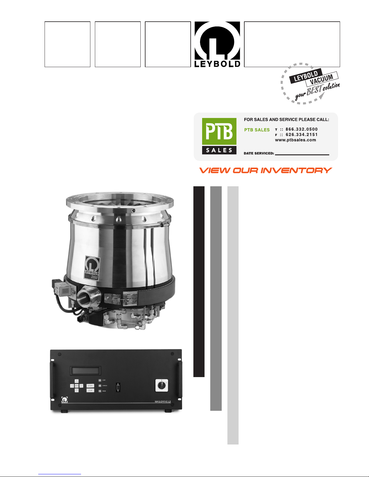
MAG 1600 C, CT
MAG W 1600 C, CT
MAG 2000 C, CT
MAG W 2000 C, CT
Turbomolecular Pump
with Magnetic Bearing
MAG.DRIVE L, L2
Electronic Frequency
Converter
Software version
MAG.DRIVE L: 1.2.3
MAG.DRIVE L2: 1.3.4 - 1.3.7
Cat. Nos.
894 14 /28
894 15 /29
894 16 /30
894 17 /31
857 24 /23
Operating Instructions
Vacuum Solutions Application Support Service
LEYBOLD VACUUM
GA 05.130/3.02
Page 2

Description
Contents
Page
1 Description . . . . . . . . . . . . . . . . . . . . . . . . . 3
1.1 System overview . . . . . . . . . . . . . . . . . . . . . . 3
1.2 Compatibility with pumped media . . . . . . . . . . 4
1.3 Design of the MAG . . . . . . . . . . . . . . . . . . . . 4
1.4 Function and design of the MAG.DRIVE . . . . 6
1.5 Standard specification . . . . . . . . . . . . . . . . . . 8
1.6 Technical data . . . . . . . . . . . . . . . . . . . . . . . . 9
1.7 Ordering information . . . . . . . . . . . . . . . . . . 10
2 Installation . . . . . . . . . . . . . . . . . . . . . . . . 22
2.1 General safety information . . . . . . . . . . . . . . 22
2.2 Unpacking - storing - transportation . . . . . . . 22
2.3 Operating environment . . . . . . . . . . . . . . . . 23
2.4 Connecting the MAG
to the vacuum chamber . . . . . . . . . . . . . . . . 23
2.5 Connecting the backing pump . . . . . . . . . . . 28
2.6 Connecting the cooling water . . . . . . . . . . . . 28
2.7 Connecting the purge gas . . . . . . . . . . . . . . 30
2.8 Installing the MAG.DRIVE . . . . . . . . . . . . . . 32
2.8.1 Power supply connection X10 . . . . . . . . . . . 33
2.8.2 Pump connection . . . . . . . . . . . . . . . . . . . . . 33
2.8.3 Control plug X1 . . . . . . . . . . . . . . . . . . . . . . 36
2.8.4 Interface connector . . . . . . . . . . . . . . . . . . . 38
2.8.5 Connection X33 . . . . . . . . . . . . . . . . . . . . . . 39
3 Operation . . . . . . . . . . . . . . . . . . . . . . . . . 40
3.1 Switching on . . . . . . . . . . . . . . . . . . . . . . . . 40
3.2 Operation . . . . . . . . . . . . . . . . . . . . . . . . . . 41
3.3 Switching off . . . . . . . . . . . . . . . . . . . . . . . . 41
4 Converter Control . . . . . . . . . . . . . . . . . . . 43
4.1 Functions of the front panel keys . . . . . . . . . 43
4.2 Operating display . . . . . . . . . . . . . . . . . . . . . 43
4.3 Remote control . . . . . . . . . . . . . . . . . . . . . . 44
4.4 Operating statuses . . . . . . . . . . . . . . . . . . . 46
4.5 Operating menu for the MAG.DRIVE L . . . . . 48
4.5.1 Basic menu . . . . . . . . . . . . . . . . . . . . . . . . . 48
4.5.2 Settings converter . . . . . . . . . . . . . . . . . . . . 49
4.5.3 Settings pump . . . . . . . . . . . . . . . . . . . . . . . 50
4.5.4 Settings active magnetic bearing . . . . . . . . . 50
4.5.5 Settings temperature management system . 51
4.5.6 Settings purge / vent . . . . . . . . . . . . . . . . . . 51
4.5.7 Total view of the menu . . . . . . . . . . . . . . . . . 52
4.6 Operating menu for the MAG.DRIVE L2 . . . . 53
4.6.1 Basic menu . . . . . . . . . . . . . . . . . . . . . . . . . 53
4.6.2 Settings converter . . . . . . . . . . . . . . . . . . . . 54
4.6.3 Settings pump . . . . . . . . . . . . . . . . . . . . . . . 55
4.6.4 Settings temperature management system . 55
4.6.5 Settings purge / vent . . . . . . . . . . . . . . . . . . 56
4.6.6 Total view of the menu . . . . . . . . . . . . . . . . . 57
4.7 Temperature management system . . . . . . . . 58
4.7.1 TMS for the MAG.DRIVE L . . . . . . . . . . . . . 58
4.7.2 TMS for the MAG.DRIVE L2 . . . . . . . . . . . . 60
5 Maintenance . . . . . . . . . . . . . . . . . . . . . . . 62
5.1 Removing the pump from the system . . . . . . 62
5.2 Service at Leybold’s . . . . . . . . . . . . . . . . . . 64
6 Troubleshooting . . . . . . . . . . . . . . . . . . . . . 65
6.1 Troubleshooting for the MAG.DRIVE L . . . . . 66
6.1.1 Warning and failure messages . . . . . . . . . . . 66
6.1.2 Failure messages . . . . . . . . . . . . . . . . . . . . 67
6.1.3 Warning messages . . . . . . . . . . . . . . . . . . . 68
6.1.4 Malfunctions . . . . . . . . . . . . . . . . . . . . . . . . 69
6.2 Troubleshooting for the MAG.DRIVE L2 . . . . 70
6.2.1 Warning messages . . . . . . . . . . . . . . . . . . . 70
6.2.2 Failure messages . . . . . . . . . . . . . . . . . . . . 72
6.2.3 Malfunctions . . . . . . . . . . . . . . . . . . . . . . . . 77
Certifications . . . . . . . . . . . . . . . . . . . . . . . . 78
Forms . . . . . . . . . . . . . . . . . . . . . . . . . . . . . 81
Figures
The references to diagrams, e. g.(1/2) consist of the Fig.
No.and the Item No. in that order.
We reserve the right to alter the design or any data given
in these Operating Instructions. The illustrations are not
binding.
The Operating Instructions are included with the pump
and the converter. If they have different editions, the
version delivered with the pump describes the pump
correctly and the version delivered with the converter
describes the converter correctly. The version number
is the digit behind the „/“ in the GA No.. Example: GA
05.130/1.02 is the first edition.
Differences between the versions:
/1 → /2
• We added the operation diagram and the pumping
speed curve for the MAG W 1600.
• We corrected some minor text mistakes.
/2 → /3
• We separated the Troubleshooting for the
MAG.DRIVE L & L2 and made it more detailed for
the MAG.DRIVE L2.
• We added technical data, the dimensional drawing,
the operation diagram, and the pumping speed
curve for the MAG 1600.
• We added ordering data.
• We added an installation instruction for the splinter
guard.
• We corrected some minor text mistakes.
Thus, you may use v ersion /3 instead of v ersions /1 and
/2 for the pump and the converter.
If you have a MAG pump with a MAG.DRIVE 2000 converter you must use the Operating Instructions delivered with the converter for the operation of the converter.
2
GA 05.130/3.02 - 05/98
Page 3
Description
3
GA 05.130/3.02 - 05/98
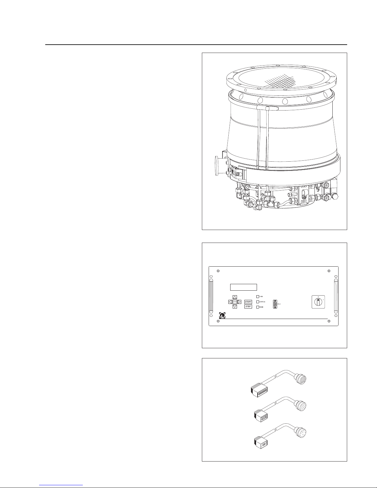
Fig. 1 MAG W 2000 CT
MAG.DRIVE L(2)
Fig. 2 MAG.DRIVE Front panel
1 Description
1.1 System overview
The Leybold MAG pumping system consists of:
• The MAG W 1600, MAG 2000, or MAG W 2000
turbopump
The MAG are turbomolecular pumps utilizing magnetic bearings.They are designed to evacuate vacuum
chambers down to pressure values in the high-vacuum range and to pump high gas throughputs.
The C versions are equipped with a purge gas valve
and a Pt 100 temperature sensor for the cooling water
temperature.
The CT versions are additionally equipped with a
temperature management system (TMS) to control
the base flange temperature.
The pumps are available with 2 different rotors:
MAG version: 11 turbo pump stages
MAG W version: 6 turbo pump stages and 1 drag
stage.
• The MAG.DRIVE L or MAG.DRIVE L2
frequency converter
The electronic converter converts the single-phase
line supply voltage into a three-phase DC voltage to
drive the pump motor.It also evaluates measured signals and controls
- the pump functions
- the temperature management system (TMS) and
- the active magnetic bearing system
• A cable set consisting of:
- BEARING cable
- TMS cable
- DRIVE cable
Fig. 3 Cable Set
Page 4

Description
1.2 Compatibility with
pumped media
The MAG (W) 1600/2000 C/CT are specifically designed
for the needs of the semiconductor industry.
Corrosion protection
To protect the pump from corrosive gases it is mandatory
to use dry Nitrogen purge during operation of the
pump.The purge gas protects the bearing section and
the motor from corrosive gases.
The rotor and the stator of the pump are KEPLA-coated
to prevent corrosiv e attac k caused b y the process gases.
The corrosion protection of the pump is effective only
when the pump is protected from moisture during
standstill and storage. If the process gas contains moisture, contact Leybold for recommendations.
Sublimation
Some media (e.g. AlCl3) can sublimate in the pump and
form deposits. Thick coatings can infringe on the requi-
red operating clearence and ultimately cause the pump
to seize.These deposits can also react with moisture and
generate corrosive gases (e.g. HCl).This can become
very critical when the pump is exposed to air. Deposits
can be avoided in many processes by heating the pump
with TMS (Temperature Management System).
The TMS is integrated in all CT-versions.The pur pose of
the TMS is to keep the baseflange temperature in a constant range. To achieve the temperature the pump is
equipped with a heaterband.
Some media ( e.g. metall organic compounds ) can
decompose at the hot surface of the pump and build layers. Please direct any inqueries to the manufacturer.
Ignition danger
During operation the pressure inside the MAG is so low
that there is no danger of ignition (at pressures below
about 100 mbar). A hazardous condition will be created
if flammable mixtures enter the hot pump at pressures
above 100 mbar. Dur ing operation the pump can reach
temperatures as high as 120°C (248°F). If the pump is
damaged, sparks could occur which could ignite explosive mixtures.
Please consult us regarding the media which can safely
be handled with this unit, with or without purge gas.
4
GA 05.130/3.02 - 05/98
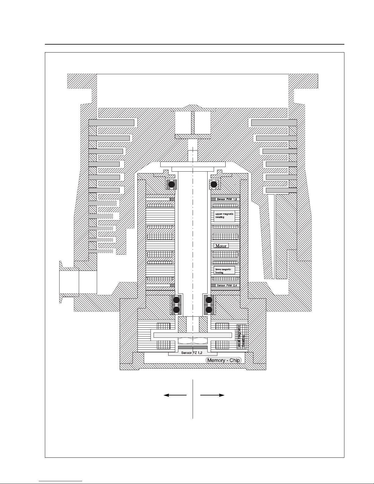
1.3 Design of the MAG
The MAG comprises basically the pump housing, the
multistage rotor with the stator package, the drive, and a
magnetic bearing.
Rotor
The rotor is made from a high strength aluminium alloy.
The rotor and the lower stator plates are protected with
a special ceramic layer ( KEPLA-coat ). The standard
rotor is a multi-stage axial-flow turbine.In addition to the
turbine stage the wide range rotor has a screw stage.
Both rotors are machined from one piece and the geometry of the the blades is optimized for high compression and pumping speed of the typical gases used in semiconductor manufacturing processes ( e.g.SF6, Ar, BCl3).
Bearings
The MAG 1600/2000 has a built-in precision 5-axis controlled magnetic bearing. The rotor is suspended by
trouble-free magnets:
• along two orthogonal axes in each of two radial planes
• and completely in the axial direction
The bearing concept allows for low vibration operations
and insures operation of the pump in any mounting position. Magnetic bearings also guarantee ultra-clean vacuum because no grease is used for lubrication of bearings.
Two touch down bearings are provided to stabilize the
rotor mechanically if impacts occur during operation.
They are only used in case of the breaking of the power
supply cable during operation, strong shocks, or faulty
electronics.
Motor and control
A DC motor without commutator is used to power the
rotor.
Drive voltage for the motor and the operating voltage for
the magnetic bearing are supplied by the MAG.DRIVE
frequency converter.It also handles the automatic monitoring of these systems.
The pump is equipped with a data storage device which
stores the important operating parameters during the
complete operation time of the pump.
The converter monitors continously all important operating parameters and provides warning and alarm signals
in case the operating conditions exceed the specification
or the set threshold.
Page 5
GA 05.130/3.02 - 05/98
Description
5
Fig. 4 Section of a MAG (W) 2000
Wide range rotorStandard rotor
Page 6

GA 05.130/3.02 - 05/98
Description
6
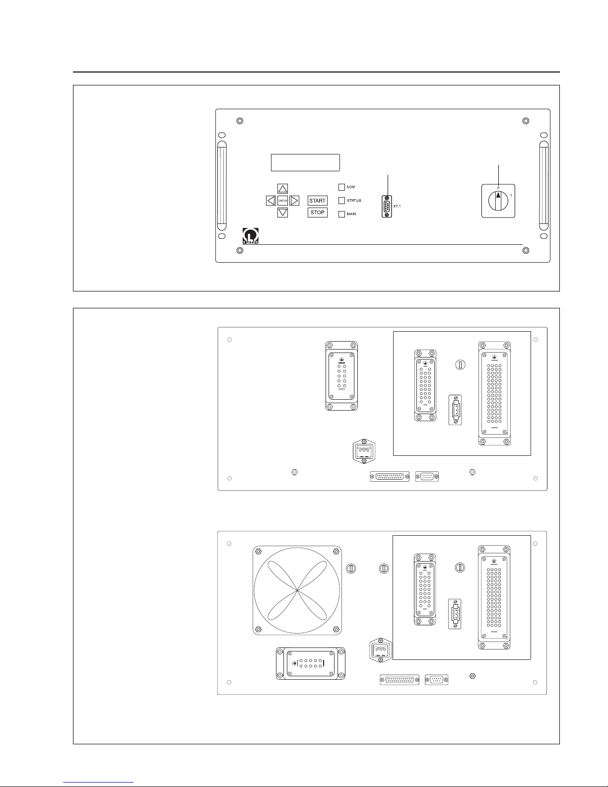
Front panel
Main switch
9-pin connecting socket for the RS232 interface
7 short-stroke keys
1 backlit LCD with 2 lines, each 16 characters, 8 mm
character height
1 green/red STATUS LED
1 green COM LED (communications interface)
1 green MAIN LED (line supply voltage)
Rear panel
X1 25-pin D socket connector for remote monitoring
and open-loop control
X7.29-pin D connector for RS232
X10 3-pin Hirschmann connector for the connection to
the mains supply
X24 64-pin Harting socket connector for internal sen-
sors and magnetic bearing connection
X26 10-pin Harting socket connector for the motor
connection
X31 25-pin Harting socket connector for the TMS and
purge valve connection
X33 3-pin terminal strip, 24 V output voltage (e.g. for the
power failure airing valve)
F1 Fuse for mains power supply (only MAG.DRIVE L2)
F2 Fuse for power supply of the active magnetic bea-
ring (only MAG.DRIVE L2)
F3 Fuse for the heating (TMS)
1 or 2 protective earth terminals
1.4 Function and design of
the MAG.DRIVE
The MAG.DRIVE L and MAG.DRIVE L2 electronic converters are used to drive the MAG turbo-molecular
pumps.
The electronic converters convert the single-phase line
supply voltage into a three-phase DC voltage to control
and monitor the electronically-commutated DC motor. It
also evaluates measured signals and controls (openloop and closed-loop) the pump functions.
The temperature management system (TMS) and the
magnetic bearing control system are integrated into the
converter.The TMS regulates the pump temperature by
switching the heating on/off or cooling the pump. The
magnetic bearing control system actively controls the
pump rotor in five axes (closed-loop control).
All parameters required for pump operation and the
listed faults and operating hours are stored in a non-volatile memory in the pump.When the converter is switched
on, the data are loaded into the converter from the pump.
The outputs of the electronic converter are no-load and
short-circuit proof.
The electronic converter can be connected via its serial
interface to external open-loop control and monitoring
devices. More detailed information on the serial interface
and the interface protocol are provided in the Option
Manual “MAG.DRIVE serial interface”.
For remote control via control connector X1 we recommend that either a relay or optocoupler is used to provide electrical isolation.
Housing
The converter is supplied with a closed housing. It can
be installed in a 19” cabinet
Page 7
X1 X7.2
X26
X31
F3
PEPE
1
13
14
25
1
ABCD
2
3
4
5
6
7
8
9
10
11
12
13
14
15
16
ABCD
1
2
3
4
5
6
7
8
9
10
11
12
13
14
15
16
X24
4
5
9
3
2
1
10
8
7
6
1
2
3
4
5
6
7
8
9
1
2
3
4
5
6
7
8
9
CBA
1
5
6
9
X10
1
3
1 2 3
s
X33
X7.2
PE
X1
X33
F3
X24
X31
X26
X10
PE
X1
X7.2
X26
X31
F3
PE
1
13
14
25
1
ABCD
2
3
4
5
6
7
8
9
10
11
12
13
14
15
16
ABCD
1
2
3
4
5
6
7
8
9
10
11
12
13
14
15
16
X24
1
2
3
4
5
6
7
8
9
1
2
3
4
5
6
7
8
9
CBA
1
5
6
9
X10
1
3
1 2 3
s
F1F2
X33
4
5
9
3
2
1
10
8
7
6
X7.2
PE
X1
X33
F3
X24
F1
X31
F2
X26
X10
GA 05.130/3.02 - 05/98
Description
7
MAG.DRIVE L(2)
Connection serial
interface RS 232
Fig.6 Rear panel with connections
Fig. 5 Front panel
Main switch
X1 Connection control plug
X7.2 Connection serial interface
RS 232
X10 Mains connection
X24 Connection magnetic
bearing
X26 Connection pump motor
X31 Connection TMS
X33 Output 24 V
F1 Fuse mains
F2 Fuse bearing
F3 Fuse TMS
PE Protective earth
MAG.DRIVE L
MAG.DRIVE L2
Page 8

Description
8
GA 05.130/3.02 - 05/98
1.5 Standard specification
MAG
The turbomolecular pumps are shipped complete,
sealed in a PE bag containing a desiccant.
The maximum effective life of the desiccant is one year.
The intake flange is sealed with a transport seal, the
forevacuum flange with a plastic cap.
For the intake flange, a centering ring with FPM O-ring,
outer ring, and a splinter guard are enclosed.
We also provide the bolts for attaching the pump to your
tool.To avoid any safety risk we highly recommend using
only the bolts provided with the pump.Refer also to Section 2.4 „Connecting the MAG ...“.
The electronic frequency converter MAG DRIVE as well
as the cables required for operation must be ordered
seperately.
In addition, a seal kit is included to seal the pump tightly
if it is removed from the process.
MAG.DRIVE
• Converter
• Line supply cable with USA connector, approx.3m
• Line supply cable with EURO connector, approx. 3 m
• Spare fuses (miniature fuses 5 x 20 mm)
F1 for the mains power supply (F8A) (only
MAG.DRIVE L2)
F2 for the power supply of the active magnetic bearing (T3.15A) (only MAG.DRIVE L2)
F3 for the heating (F4A)
Cable Set
• Bearing cable
• TMS cable
• Drive cable
Page 9

Description
1.6 Technical data
MAG 1600 C/CT W 1600 C/CT 2000 C/CT W 2000 C/CT
Pumping speed for N2measured
with splinter guard (PNEUROP) l·s
-1
1250 1300 1550 1650
Gas flow (continuous operation
with Argon) sccm 1000 1000 1000 1000
Compression for N
2
>10
8
>10
8
>10
8
>10
8
Ultimate pressure as to DIN 28 400 mbar < 10
-8
< 10
-8
< 10
-8
< 10
-8
Max. forevacuum pressure
with Nitrogen mbar 1.5 3.3 1.5 3.3
with Argon mbar 1.5 4.1 1.5 4.1
Rotor Speed min
-1
28,800
Run-up time min < 10
Braking time with/without venting min 1 / < 7.5
Cooling water
Cooling connection,
Swagelok elbow for tube OD mm 6.4 (1/4“)
Cooling water temperature °C 15 to 30
°F 59 to 86
Base flange temperature C version °C 30 to 50
(depending on the load) °F 86 to 122
Base flange temperature CT version °C 30 to 63
(controlled) °F 86 to 145
Weight approx. kg 70 65 68 62
High-vacuum connection flange DN 200 ISO-F 200 ISO-F 250 ISO-F 250 ISO-F
Forevacuum connection flange DN 40 KF 40 KF 40 KF 40 KF
Recommended backing pump DRYVAC 100 50 100 50
Admissible ambient temperature °C 5 to 40
°F 40 to 104
Storage temperature °C -10 to +60
°F 14 to 140
9
GA 05.130/3.02 - 05/98
Page 10

Purge Gas
Purge gas connection pressure, abs. 1.2 - 2.0 bar
Purge gas: dry nitrogen, argon or similar
Purge gas throughput
at purge gas pressure 1.5 bar abs. 0.6 mbar·l·s
-1
36 sccm
Connection:VCR Nut 1/4“
MAG.DRIVE
Voltage range 200 - 240 V +10% -15%
Line supply frequency 50 / 60 Hz
Load
Stand-by approx. 100 W
Continuous (rated speed) 810 W
Maximum 1800 W
Max. voltage motor 60 V
Maximum pump current (Accel.) 20 A dc_peak
Continuous pump current, max. 13 A dc_peak
Maximum frequency 480 Hz
Load capability, relay output 42 V, 1 A
Temperature during operation
MAG.DRIVE L 0-40° C
MAG.DRIVE L2 0-45° C
Storage temperature - 10° C to + 60° C
Relative air humidity Class F acc. to DIN 400 40
Weight 16 kg
Dimensions W x H x D (mm) 465 x 222 x 350
+ connector depth 130
The units have degree of protection IP20 in accordance
with EN 60529
(protection against the ingress of solid foreign bodies >
12 mm diameter (finger). It is not protected against the
ingress of water with damaging effects.)
An increased degree of protection, e.g.IP54 can only be
implemented by mounting the converter in an additional
housing.
1.7 Ordering data
Order No.
MAG 1600 C 894 14
MAG W 1600 C 894 15
MAG 2000 C 894 16
MAG W 2000 C 894 17
MAG 1600 CT 894 28
MAG W 1600 CT 894 29
MAG 2000 CT 894 30
MAG W 2000 CT 894 31
Seal Kit DN 200 200 91 684
Seal Kit DN 250 200 91 641
MAG.DRIVE L converter 857 24
MAG.DRIVE L2 converter 857 23
Connecting cables, converter / pump
Length Cable Cable Cable
BEARING DRIVE TMS
————————————————————————
3 m 859 50 859 51 859 52
5 m* 859 53 859 54 859 55
10 m* 859 56 859 57 859 58
20 m* 859 62 859 63 859 64
3 m with
bended plugs 859 68 859 69 859 70
The cables with straight plugs are shown in Fig.3, the
cables with bended plugs in Fig. 34.
• MAG.WIN, an operator control interface
which can run under Windows with user
instructions as Windows help on request
• Connecting cable serial interface (front panel,
9-pin D-connector), approx. 5 m long on request
* only permissible if the pump is mounted in a vertical position
Description
10
GA 05.130/3.02 - 05/98
Page 11
Description
11
GA 05.130/3.02 - 05/98
483
465
146
10
7
222
130
353
20
233
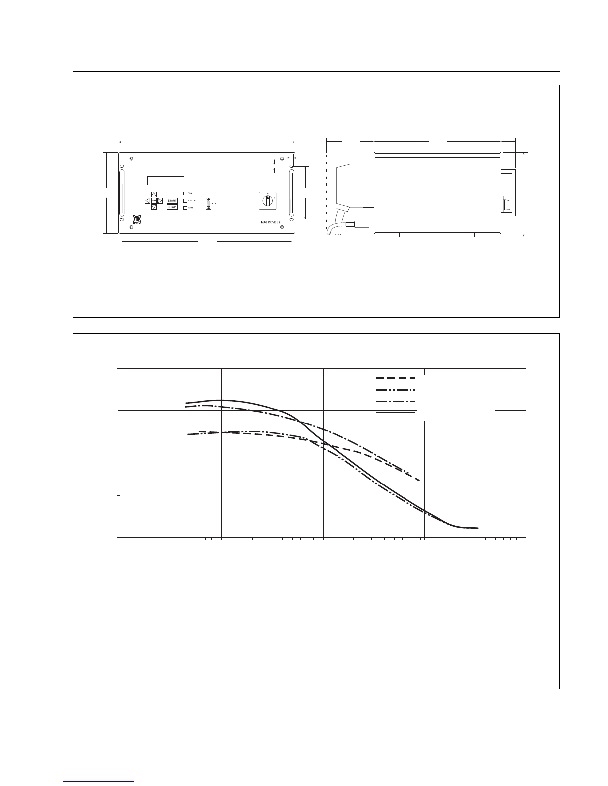
Fig. 7 Dimensional drawing of the MAG.DRIVE; dimensions in mm
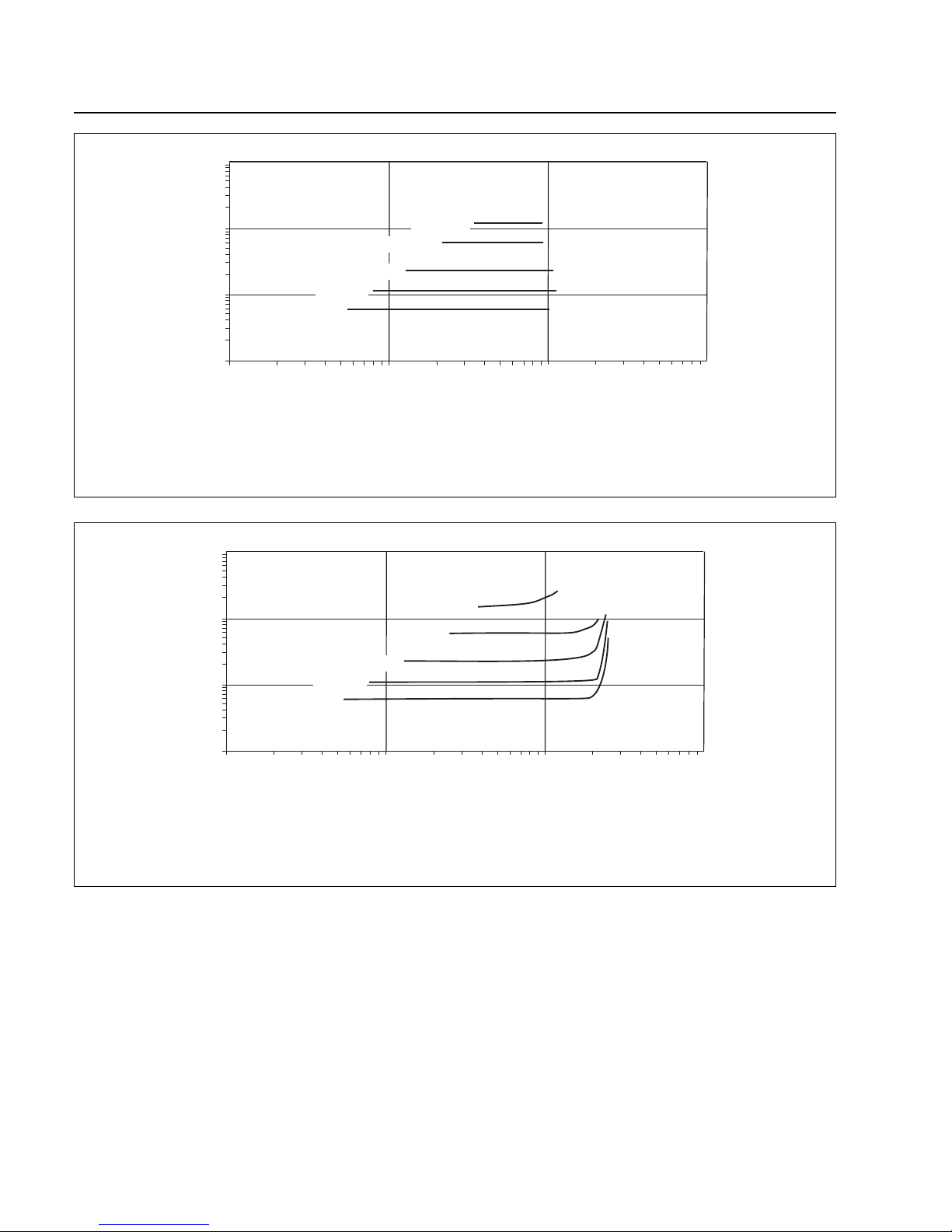
1500
1000
500
0
2000
10
-2
10
-1
1
Torr
10
-3
10
-4
l/s
MAG 1600 CT
MAG W 1600 CT
MAG 2000 CT
MAG W 2000 CT
High Vacuum Pressure
Fig. 8 Pumping speed curves for Nitrogen
Pumping speed
Rotor speed 480 Hz
Purge gas flow 36 sccm Nitrogen
with splinter guard
Forepump
for MAG 1600 CT D 65 B + WS 501
for MAG W 1600 CT D 65 B + WS 251
for MAG 2000 CT D 65 B + WS 501
for MAG W 2000 CT D 65 B + WS 251
Pipe 1 m DN 40
according to PNEUROP
Page 12
Description
12
GA 05.130/3.02 - 05/98
10
-1
10
-2
10
-3
10
-4
50 sccm
100 sccm
200 sccm
500 sccm
1000 sccm
10
-2
10
-1
1 10
Torr
Torr
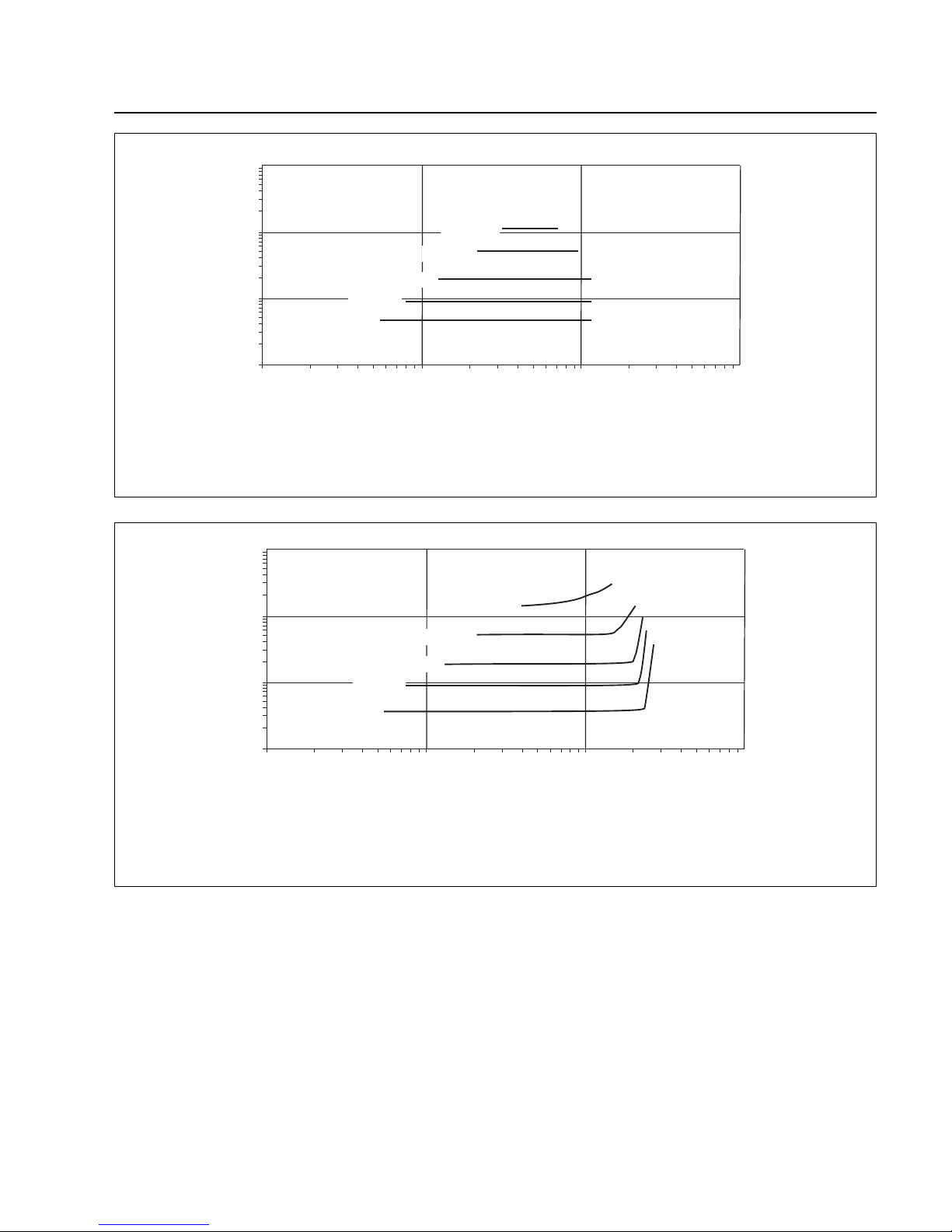
Fig. 10 MAG W 1600 C/CT: operation diagram for nitrogen
High vacuum pressure
Forevacuum pressure
Rotor speed 480 Hz
Purge gas flow 36 sccm Nitrogen
with splinter guard
Forepump D 65 B + WS 251
Pipe 1 m DN 40
according to PNEUROP
10
-1
10
-2
10
-3
10
-4
50 sccm
100 sccm
200 sccm
500 sccm
1000 sccm
10
-2
10
-1
1 10
Torr
Torr
Fig. 9 MAG 1600 C/CT: operation diagram for nitrogen
High vacuum pressure
Forevacuum pressure
Rotor speed 480 Hz
Purge gas flow 36 sccm Nitrogen
with splinter guard
Forepump D 65 B + WS 501
Pipe 1 m DN 40
according to PNEUROP
Page 13
Description
13
GA 05.130/3.02 - 05/98
10
-1
10
-2
10
-3
10
-4
50 sccm
100 sccm
200 sccm
500 sccm
1000 sccm
10
-2
10
-1
1 10
Torr
Torr
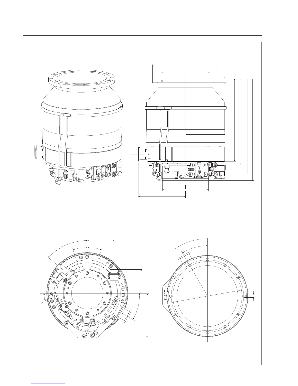
Fig. 11 MAG 2000 C/CT: operation diagram for nitrogen
High vacuum pressure
Forevacuum pressure
Rotor speed 480 Hz
Purge gas flow 36 sccm Nitrogen
with splinter guard
Forepump D 65 B + WS 501
Pipe 1 m DN 40
according to PNEUROP
10
-1
10
-2
10
-3
10
-4
50 sccm
100 sccm
200 sccm
500 sccm
1000 sccm
10
-2
10
-1
1 10
Torr
Torr
Fig. 12 MAG W 2000 C/CT: operation diagram for nitrogen
High vacuum pressure
Forevacuum pressure
Rotor speed 480 Hz
Purge gas flow 36 sccm Nitrogen
with splinter guard
Forepump D 65 B + WS 251
Pipe 1 m DN 40
according to PNEUROP
Page 14
Description
14
GA 05.130/3.02 - 05/98
DN 40
12x30° = 360°
408
202
436
368
353
322
ø285
ø210
ø339
ø199
DN 200 ISO F
30°
260
11
18°
18°
51°
30°
35°
102
192
115
16
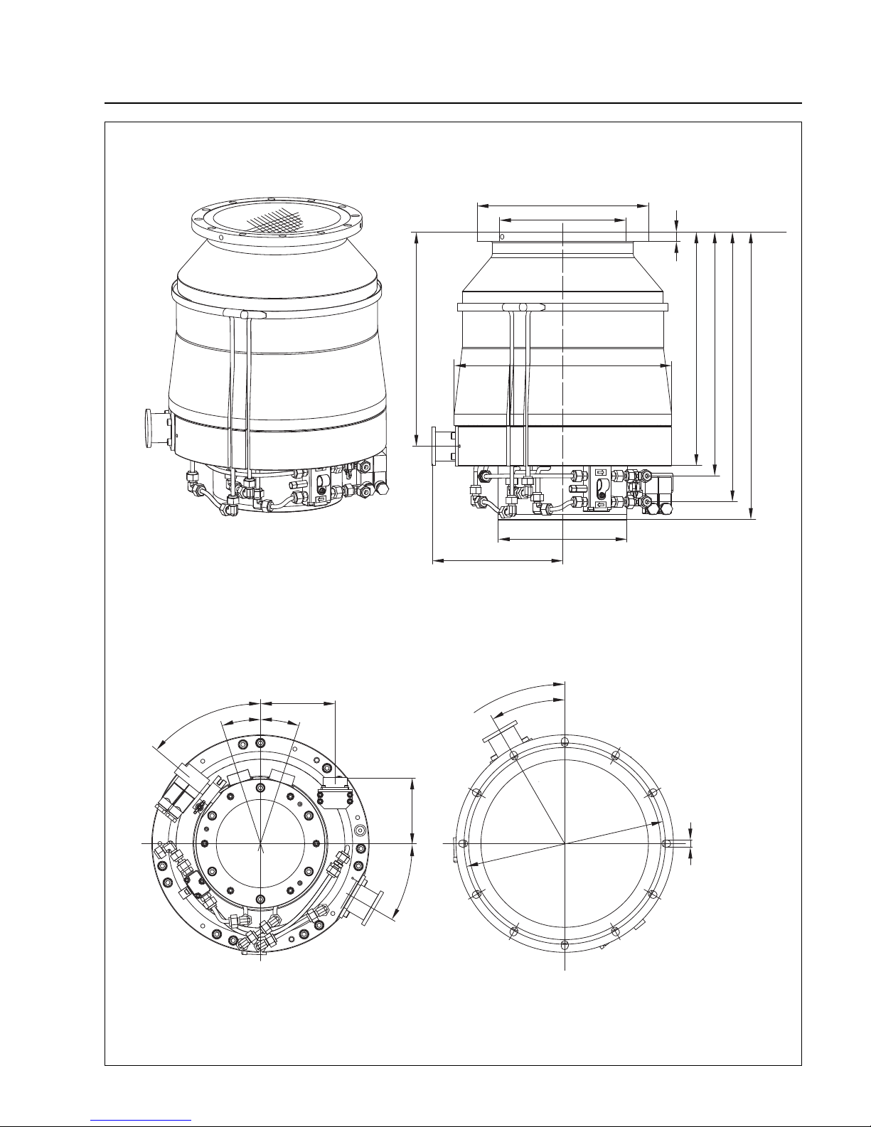
Fig. 13 MAG 1600 C, Dimensions in mm
MAG 1600 C Cat. No. 894 14
Page 15
Description
15
GA 05.130/3.02 - 05/98
322
ø285
DN 200 ISO F
ø210
DN 40
ø339
ø199
202
16
436
353
368
408
260
18°
18°
51°
30°
102
115
12x30° = 360°
30°
11
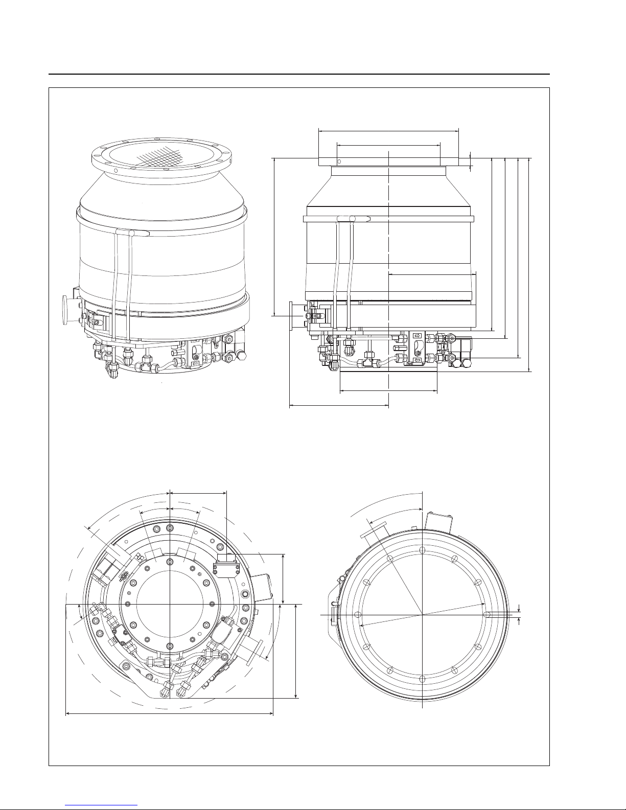
Fig. 14 MAG W 1600 C, Dimensions in mm
MAG W 1600 C Cat. No. 894 15
Page 16
Description
16
GA 05.130/3.02 - 05/98
408
202
436
368
353
322
16
ø285
ø210
ø355
ø199
12x30° = 360°
DN 40
DN 200 ISO F
30°
260
11
421
18°
18°
51°
30°
35°
102
192
115
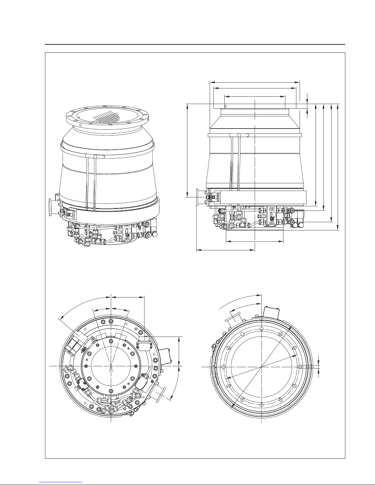
Fig. 15 MAG 1600 CT, Dimensions in mm
MAG 1600 CT Cat. No. 894 28
Page 17
Description
17
GA 05.130/3.02 - 05/98
ø310
ø285
ø210
353
368
408
436
16
DN 200ISO F
322
ø199
202
DN 40
,00
260
355
18°
18°
51°
102
115
30°
12x30° = 360°
30°
11
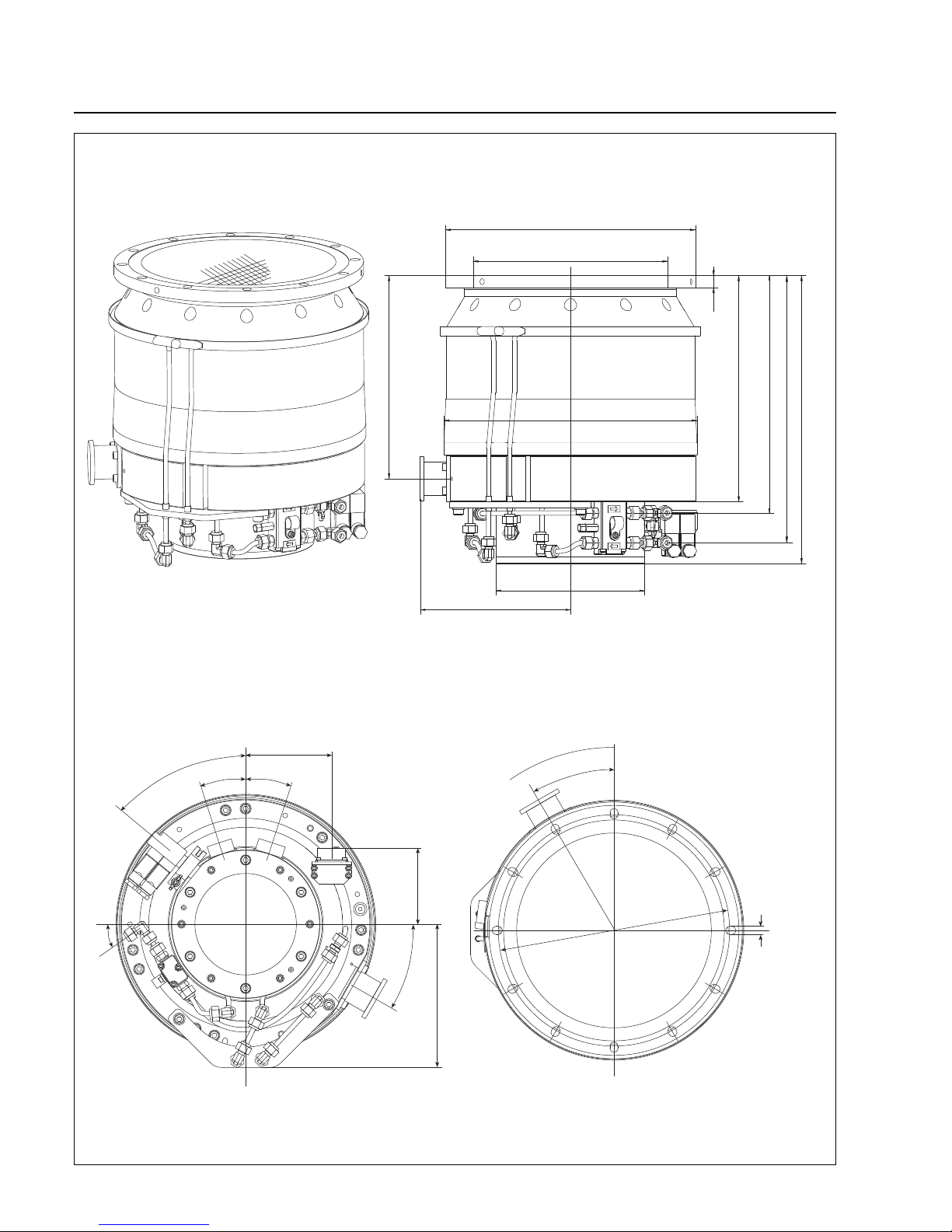
Fig. 16 MAG W 1600 CT, Dimensions in mm
MAG W 1600 CT Cat. No. 894 29
Page 18
Description
18
GA 05.130/3.02 - 05/98
DN 40
DN 250 ISO F
318
202
358
16
303
386
272
ø339
ø199
ø335
ø261
12x30° = 360°
30°
310
11
18°
18°
51°
30°
35°
102
192
115
Fig. 17 MAG 2000 C, Dimensions in mm
MAG 2000 C Cat. No. 894 16
Page 19
Description
19
GA 05.130/3.02 - 05/98
DN 40
318
202
358
16
303
386
272
ø335
ø199
ø335
ø261
12x30° = 360°
DN 250 ISO F
18°
18°
51°
35°
102
115
30°
310
11
30°
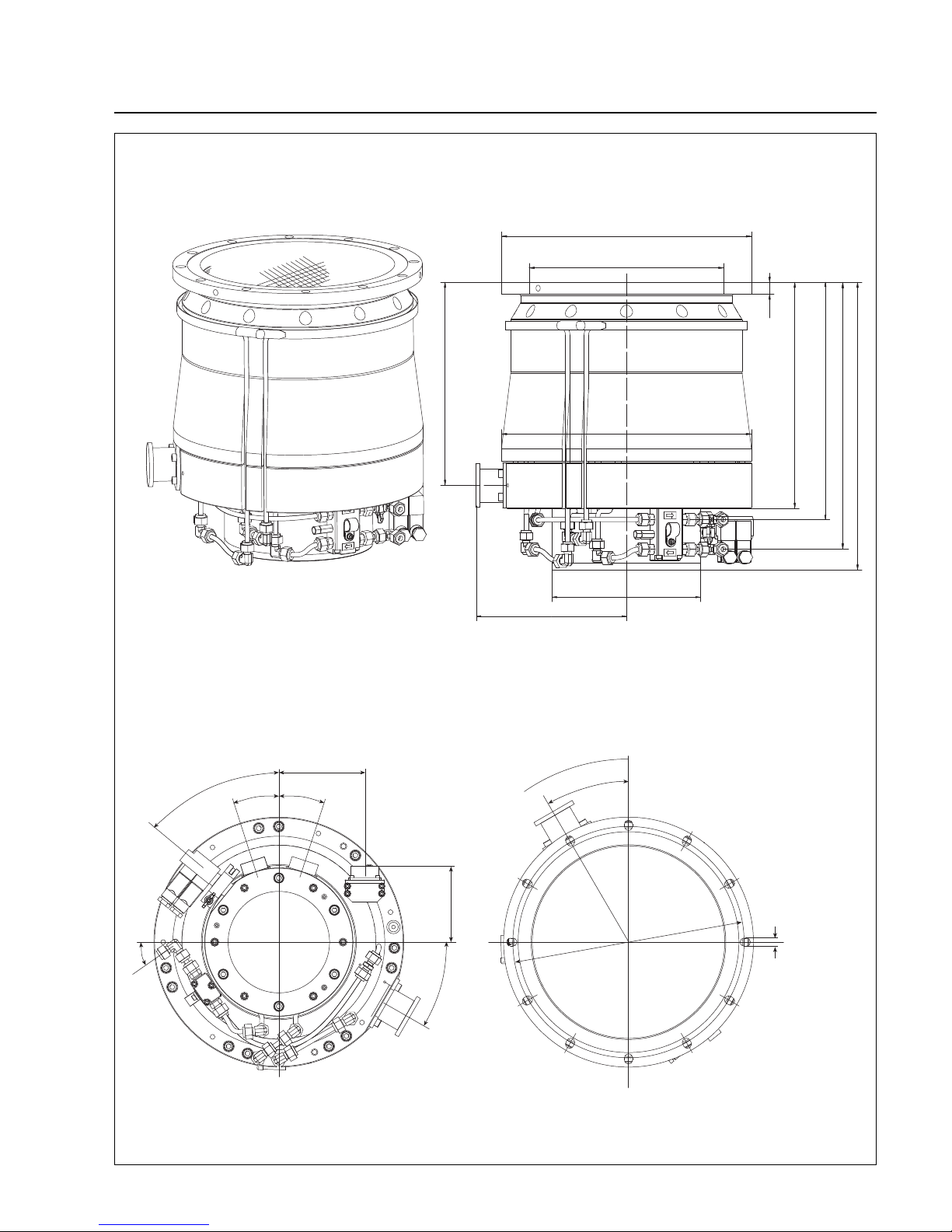
Fig. 18 MAG W 2000 C, Dimensions in mm
MAG W 2000 C Cat. No. 894 17
Page 20
Description
20
GA 05.130/3.02 - 05/98
DN 250 ISO F
DN 40
202
272
303
318
358
386
ø339
ø199
ø261
ø335
16
12x30° = 360°
421
30°
310
11
18°
18°
51°
30°
35°
102
192
115
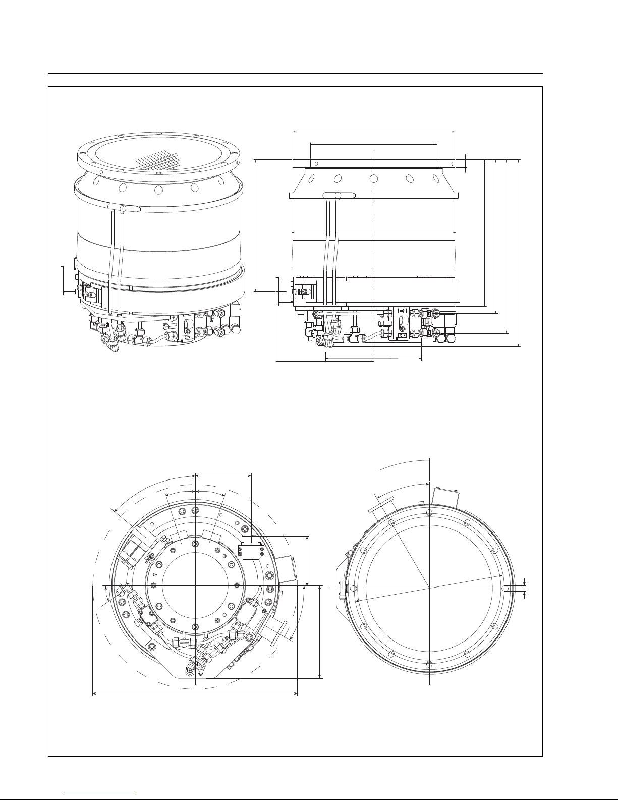
Fig. 19 MAG 2000 CT, Dimensions in mm
MAG 2000 CT Cat. No. 894 30
Page 21
Description
21
GA 05.130/3.02 - 05/98
DN 250 ISO F
DN 40
358
318
16
303
386
202
272
ø335
ø261
ø355
ø199
12x30° = 360°
18°
18°
51°
30°
35°
421
102
30°
310
11
115
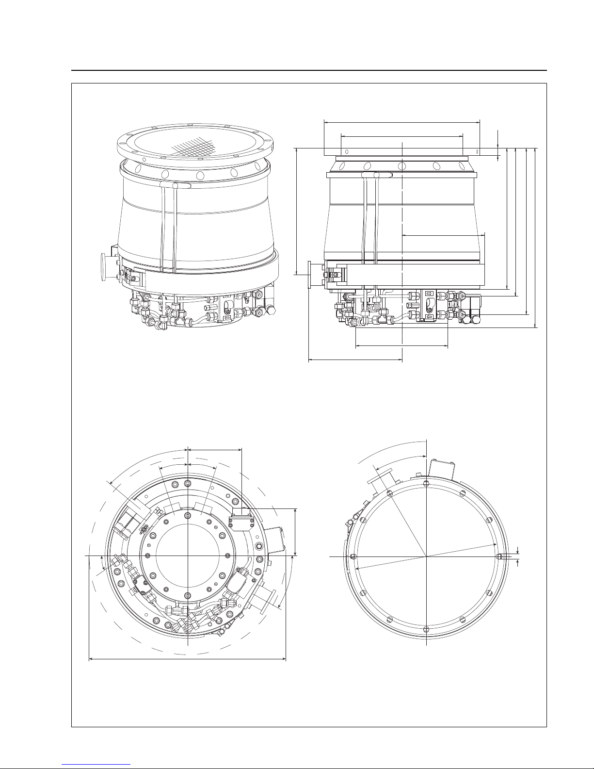
Fig. 20 MAG W 2000 CT, Dimensions in mm
MAG W 2000 CT Cat. No. 894 31
Page 22
Installation
22
GA 05.130/3.02 - 05/98
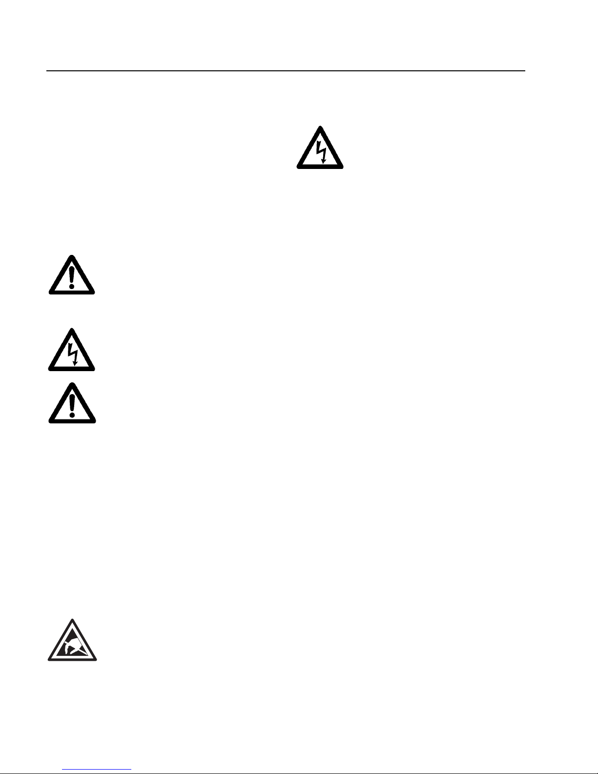
Warning
Before opening the converter, always disconnect from the mains! When applying
external voltage in excess of 42 V to terminals of the device, observe local safety
regulations!
Unauthorized device conversion and modifications are prohibited for safety reasons.
Please keep this Operating Instruction for future reference.
2.2 Unpacking - storing transportation
Remove the equipment from the transportation box and
keep the packaging. Make sure that the product has not
been damaged during transportation. If this unit is damaged contact your carrier and inform LEYBOLD if necessary. For storage of the product, use the packaging provided.
Lift the pump by the crane eyelets or mo v e it with at least
two persons.
You can position the pump on the base plate for transport with a lift-truck. Protect the pump against slipping
and tipping over.
Caution
Be careful not to damage the sockets and
coolant connections during transportation.
Do not stand below the pump while connecting or removing the MAG.
The MAG is shipped in a sealed PE bag with desiccant.
Do not open the sealed package until immediately before installing.
Do not remove the covers and blanking flanges until you
are ready to make the connections, to ensure that the
MAG is installed under the cleanest possible conditions.
2 Installation
2.1
General safety information
Warning
Indicates procedures that must be strictly observed to
prevent hazards to persons.
Caution
Indicates procedures that must be strictly observed to
prevent damage to, or destruction of the MAG.
Warning
Never expose any parts of the body to the
vacuum.
Warning
The converter has dangerous voltage
levels.
Failure to strictly follow the instructions in
this Manual can result in death, severe
bodily injuries or significant material damage.
Only suitably qualified personnel are permitted to work on the pump or converter.
Personnel m ust be completely kno wledgeable of all warning information and measures
which are specified in this Instruction
manual for transporting, installing, and operating the unit.
Qualified personnel
Qualified electrical personnel in this instruction manual
means a person who has received electrical engineering
instruction or is an electrical expert in accordance with
EN 60204, Part 1, 3.30 respectivly 3.55.
Warning
The device contain electrostatically sensitive devices (ESD)!
Page 23
Installation
23
GA 05.130/3.02 - 05/98
1
2
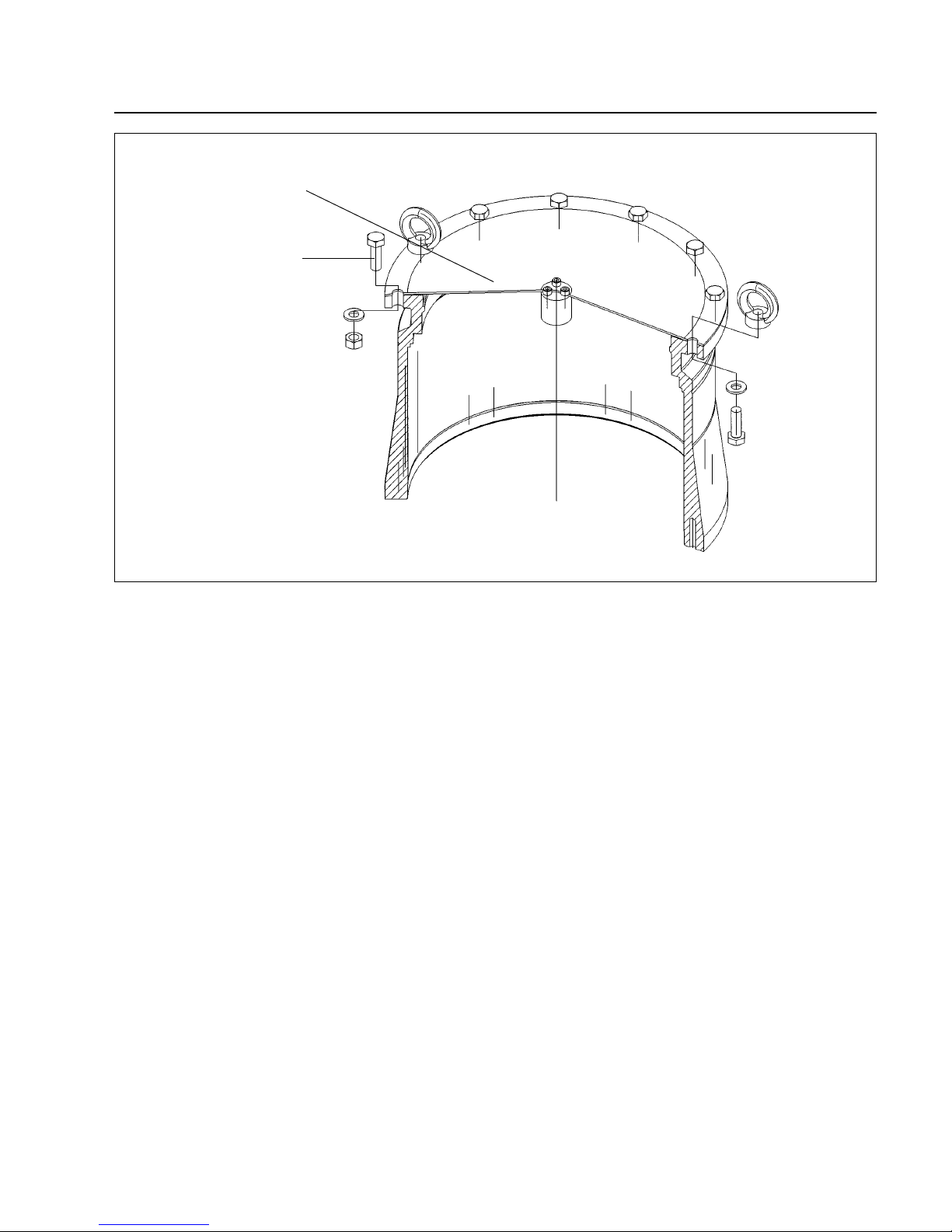
1 Aluminum cover
2 Screws
Fig. 21 Removing the transport seal
2.3 Operating environment
When using the MAG inside a magnetic field, the magnetic induction at the pump housing must not exceed 5 mT;
(1 mT (milliTesla) = 10 G (Gauß))
Exceeding this limit can cause excessive rotor heating
due to the eddy currents generated in this situation. It is
therefore necessary to provide suitable shielding in such
cases.
The standard version of the MAG is resistant to radiation
at levels up to 103Gy. (1 Gy (Gray) = 100 rad)
The ambient temperature must not exceed 40°C
(104 °F).
The noise level when the pump is running is below 70
dB(A). No acoustic insulation is required.
2.4 Connecting the MAG to
the vacuum chamber
The MAG is shipped in a sealed PE bag with desiccant.
Do not open the package until immediately before installing.
Do not remove the covers and blanking flanges until you
are ready to make the connections, to ensure that the
MAG is installed under the cleanest possible conditions.
Pay attention to maximum cleanliness when connecting.
Remove the transport seal from the intake flange.To do
so unscrew the screws (21/2) and remove the aluminum
cover.We recommend saving the transport seal for maintenance.
Page 24
GA 05.130/3.02 - 05/98
Installation
24
Foreign objects entering the pump through the high-vacuum flange can cause serious damage to the rotor.
That’s why the splinter guard must always be installed.
Damages caused during operation without the splinter
guard are excluded from warranty.
Caution
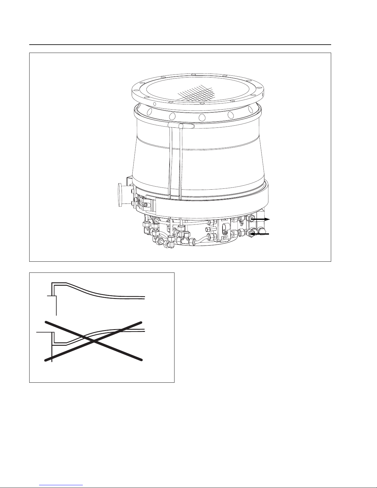
Install the splinter guard as shown in Fig.
23. Installing the splinter guard upside down
may lead to contact between splinter guard
and rotor during fast venting of the pump.
Fig. 22 Connection elements
Intake flange
Forevacuum flange
Cooling water out
Cooling water in
Correct
Wrong
Fig. 23 Installing the splinter guard
Page 25
Installation
25
GA 05.130/3.02 - 05/98
Warning
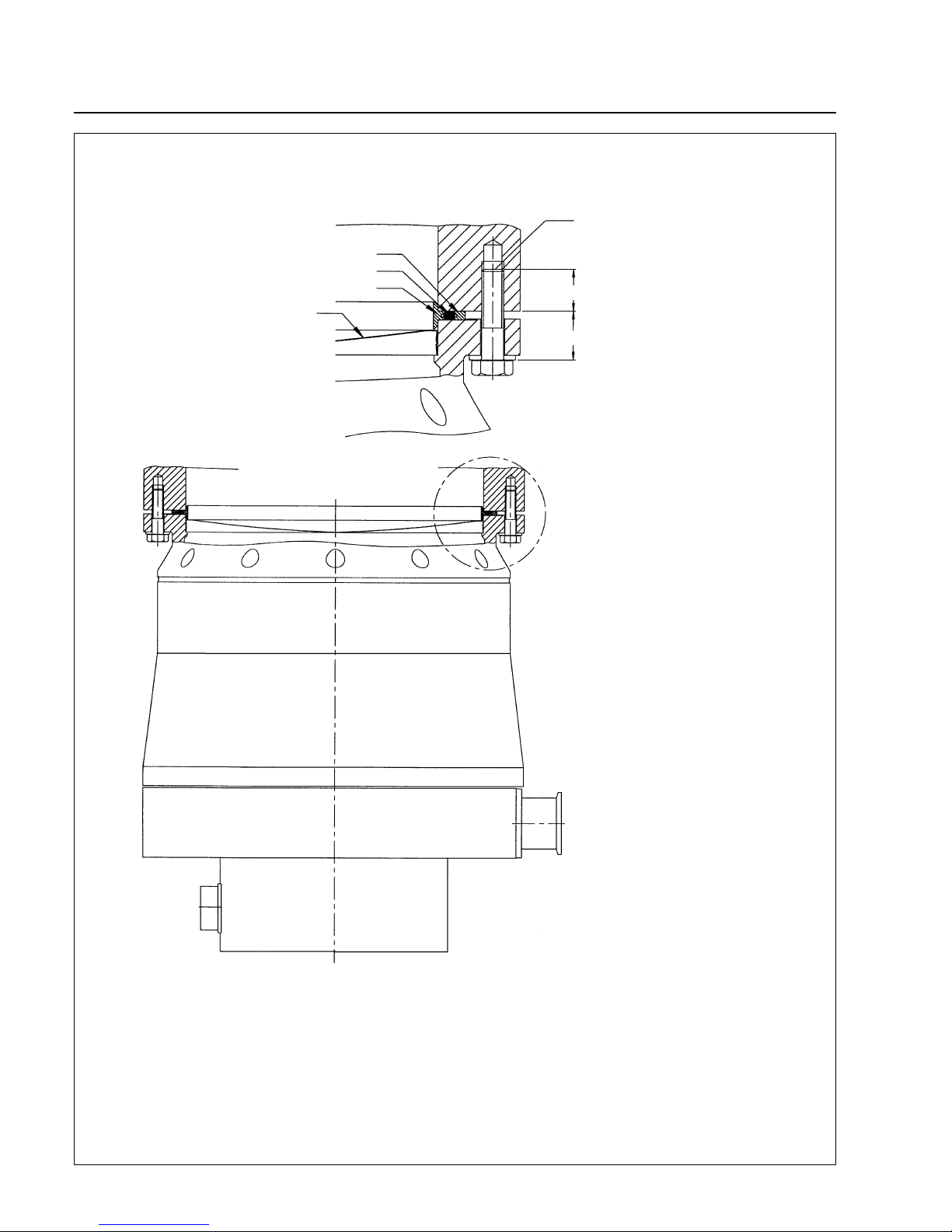
The pump must be securely attached.If the
pump should suddenly seize, inadequate
attachment could cause the pump to break
away or allow internal pump parts to be discharged. Never operate the pump (in bench
tests, for instance) without its being connected at the vacuum chamber.
If the pump should suddenly seize, the decceleration torque of 60,000 Nm will have to
be absorbed by the system. To accomplish
this, use all 12 bolts provided by Leybold for
fastening the high-vacuum flange; see also
Fig. 25.
Mount the MAG as close as possible to the vacuum
chamber. If the MAG is permanently flanged to a vacuum
chamber with a weight exceeding 500 kg, it will not be
necessary to secure it in any other way.
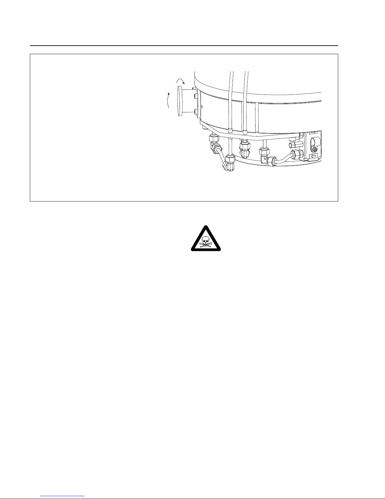
In case of lighter vacuum vessels secure the pump additionally. The pump’s bottom is equipped with tappered
holes for fastening a support; see Fig. 26.
If the pump is exposed to shocks, e.g. by a gate valve,
secure the pump so that it is supported in the direction of
the shock.
We recommend installing an isolation valve between the
pump and the chamber. The valve should be closed
during wet cleans of the chamber and in case of pump
failures which will lead to a pump shut down.The valve
should normally be closed with power off.
Warning
The basic flange heater can become so hot
during operation (> 80°C, > 176 °F) that it
represents a burn hazard:
Provide protection against contact with the
hot components.
Mounting position and cable length
If the pump is mounted in a vertical position (intake
flange up or down) the permissible length of the pumpconverter cables is 3 to 20 meters.
If the pump is mounted in a horizontal position the permissible length of the pump-converter cables is 3 meter.
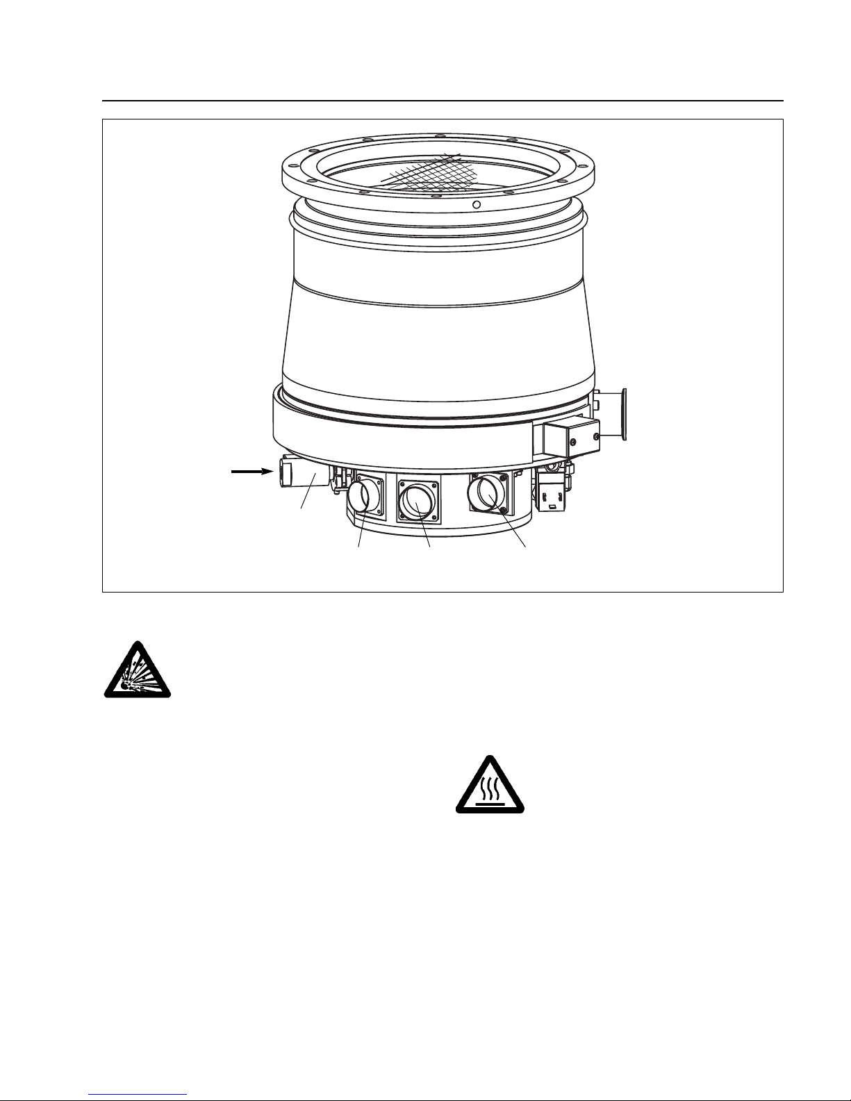
Purge gas in
TMS
connection
BEARING
connection
DRIVE
connection
Fig. 24 Connection elements
Purge gas
valve
Page 26
Installation
26
GA 05.130/3.02 - 05/98
21.5
l
l > 15 mm in aluminium
l > 10 mm in steel
Outer ring (stainless steel)
Sealing (FPM)
Centering ring (stainless steel)
Splinter guard
Max. torque = 60,000 Nm
Fig. 25 Fixing the intake flange
Bolts: M10 x 40
Quality 12.9 according to DIN 898:
0,2% yield strength > 1080 N/mm
2
Bolt torque: 40 Nm
Page 27
Installation
27
GA 05.130/3.02 - 05/98
15°
30°
70°
125°
Ø 310
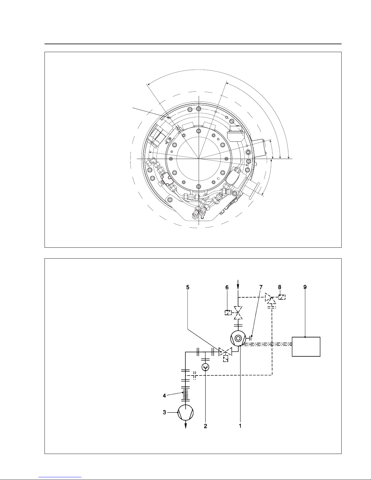
Fig. 27 Layout of a turbomolecular pump system
Key to Fig. 27
1 Turbomolecular pump
2 Forevacuum gauge point
3 Backing pump
4 Anti-vibration bellows
5 Forevacuum valve
6 High vacuum valve
7 Purge gas connection
8 Valve in the roughing line
9 Electronic frequency converter
— — — — roughing line; recommended
if shorter cycle times are to be achieved
— · — · — · — · drive, bearing, and TMS cable
Fig. 26 Fixing the pump at the bottom
Boreholes M8,
15 mm deep
Page 28
Installation
28
GA 05.130/3.02 - 05/98
2.5 Connecting the backing
pump
A two stage rotary vane pump or dry-compression
backing pump is required to support operation of the
MAG.
We recommend using the DRYVAC or our TRIVAC-B
pump for this purpose.
In case of high gas throughput, it may also be necessary
to use a roots blower to achieve the backing pressure
necessary for operating the MAG. We recommend our
RUVAC blower for this purpose or our DRYVAC 251/501
systems.
Fig. 27 shows schematically the design of a pump
system incorporating a MAG with an additional foreline
valve and an isolation v alv e between chamber and MAG.
The foreline isolation valve is recommended to protect
the MAG from shock v enting in case of uncontrolled shut
down of the backing pump. This valve must be able to
close fast enough to avoid pressure increase in the
MAG.
In case of an oil-sealed backing pump the foreline isolation valve protects the MAG from backstreaming oil
vapor during standstill.
Connect the forevacuum flange of the MAG to the
backing pump.
The torque on the forevacuum connection flange must
not exceed the values shown in Fig. 28.
Warning
The forevacuum line must be tight. Hazardous gases can escape at leaks or the
gases being pumped can react with the air
or humidity. We recommend a leak check.
2.6 Connecting the cooling
water
Cooling water specifications
Inlet temperature 15 - 30 °C
Inlet pressure 3 to 7 bar absolute
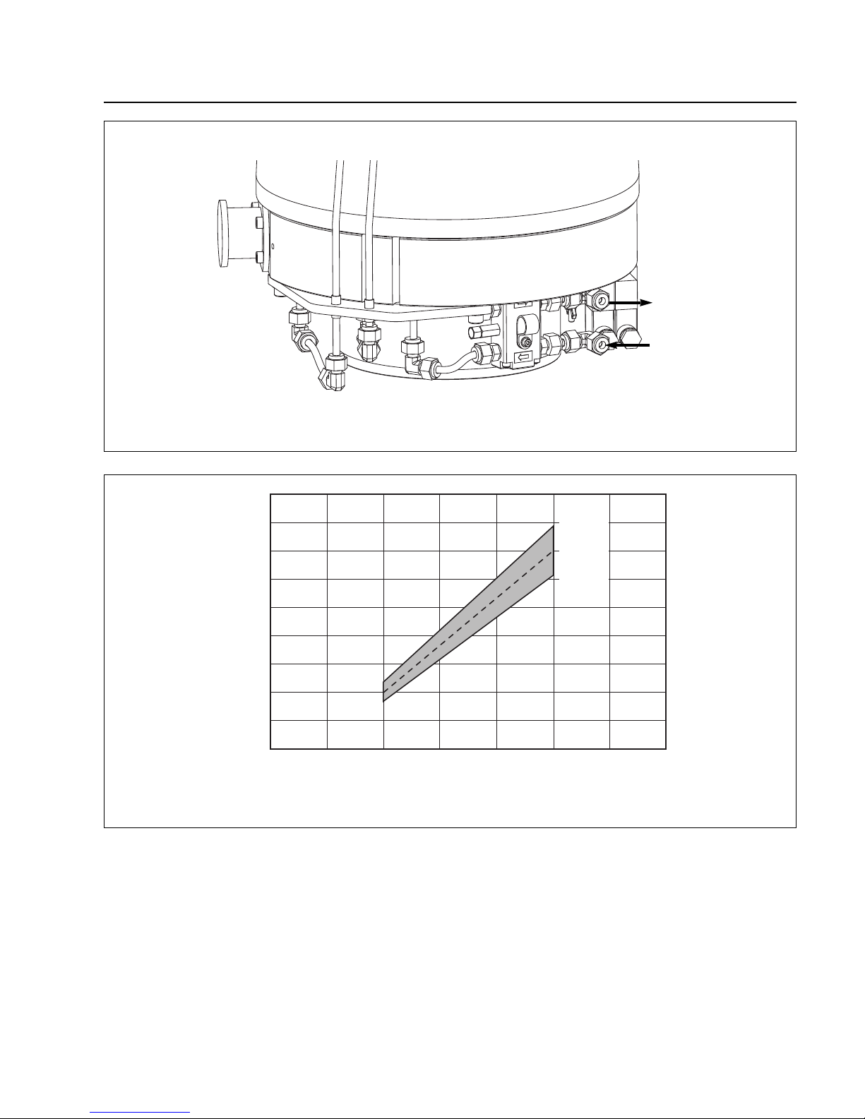
Cooling water requirement See Fig. 30
Appearance Colorless, clear,
free of oils and greases
Sediments < 250 mg/l
Particle size < 150 µm
Electrical conductivity < 500 µS/cm
pH value 7 to 8.5
Overall hardness (total alkaline earths)
max. 20 ° Ger man hardness scale
(= 3.57 mmol/l)
Further information on request.
M
M
q
M < 150 Nm
Mq< 150 Nm
Fig. 28 Maximum torques for the forevacuum connection
Page 29
Installation
29
GA 05.130/3.02 - 05/98
Connect the cooling water to the connectors;see Fig. 29.
Make sure that you do not mix up the inlet and the outlet
connection.
Tur n off the cooling water supply when the pump is
switched off in order to a void condensate f ormation in the
pump.
If you do not close the cooling water it ma y tak e longer to
achieve ultimate pressure after start up of the system.
Fig. 29 Connecting the cooling water
Cooling water out
1/4“ tube
Cooling water in
1/4“ tube
5 10 15 20 25 30 35 40
°C
220
200
180
160
140
120
100
80
60
40
l/h
Fig. 30 Recommended cooling water flow as a function of cooling water temperature
Temperature
Flow
maximum
optimum
minimum
Page 30
Installation
30
GA 05.130/3.02 - 05/98
2.7 Connecting the purge
gas
The MAG is equipped with a purge gas and venting
valve. It is controlled by the MAG.DRIVE. Additional
monitoring with a flow controller is not necessary.
Connect the purge gas and venting valve to the purge
gas supply via a pressure reducer.
Connection:VCR Nut 1/4“
Purge gas connection pressure, abs. 1.2 - 2.0 bar
Purge gas: dry nitrogen, argon or similar
Purge gas throughput
at purge gas pressure 1.5 bar abs. 0.6 mbar·l·s
-1
36 sccm
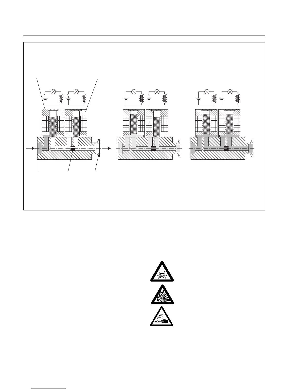
With no voltage applied the purge gas and venting valve
is closed.
The purge gas valve will be open when switching on the
MAG.DRIVE.The red LED at the purge gas valve lights.
The venting valv e can be opened via the control plug X1.
The red LED at the venting valv e lights when the valve is
open. A blind-flanged pump will be vented within 1 minute via the open venting valve.
Warning
Monitor the purge gas continuously.
Insufficient purge gas flow can result in:
- Process gases entering the motor and
bearing area of the MAG
- Process gases escaping from the purge
gas valve
- Humidity entering the pump.
24 V
24 V 24 V
Connection to Nozzle Connection to
purge gas supply pump
Purge valve venting valve
Fig. 31 Schematic drawing of purge and venting valve
Status Purge Valve
No Purge: Purge closed Purge Vent
Vent closed
Page 31
Installation
31
GA 05.130/3.02 - 05/98
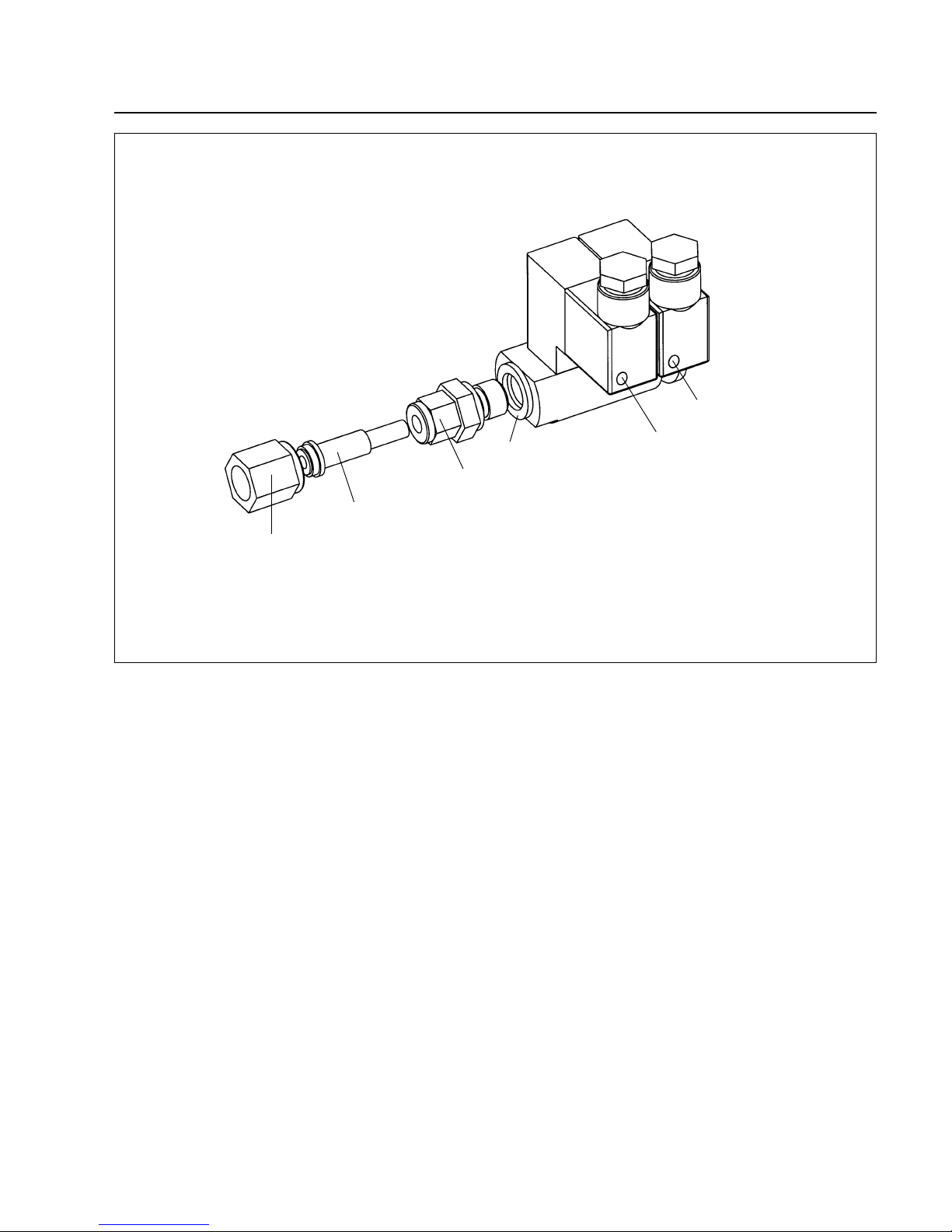
Fig. 32 Purge gas connection with connection kit
VCR Nut 1/4“
Port connector:
Tube to VCR
Male connector: Tube OD 1/4“ ISO male pipe size: 1/4“
Seal
LED purge valve
LED vent valve
Page 32
Caution
The connecting cables between the converters and pump may only be inserted or
removed when the converter is switched off
or is isolated from the line supply. If a
connector is inserted or withdrawn when
the converter is switched on, the converter
and the pump could be damaged or destroyed!
Warning
Hazardous voltages are present inside the
converter.Death or severe injury can occur
if you come into contact with these hazardous voltages. Before opening the converter, isolate the converter from the line supply, and lock the switch so that it cannot be
accidentally switched on again.
Installation instructions to maintain EMC
The MAG.DRIVE L2 complies with the Electromagnetic
Compatibility (EMC) Directives of the EC. In order to
maintain this the following installation instructions must
be observed:
• The housing must be connected to a good ground
connection (e.g. mounting rack) using a large cross
section (e.g.1.5 mm2) cable which should be as short
as possible.The PE connection is located on the rear
panel.
• To connect the pump to the converter the prescribed
Leybold cables must be used.
• A shielded cable must be used for the connections to
the terminal strip X33. The shield should be connected to ground to a low-impedance connection.
• The connection cables to the analog interface (control
plug X1) and to the serial interfaces (connectors X7.1
and X7.2) must be shielded. The shields must be
connected to the metal housings of the SUB-Dconnector and SUB-D-socket.
Installation
32
GA 05.130/3.02 - 05/98
2.8 Installing the
MAG.DRIVE
The converter can be installed in a 19” cabinet
Mounting depth: 350 mm + 130 mm for the connectors
on the rear side (133/4“ + 51/8“);
height: 5 height units (83/4“)
Caution
In order to guarantee sufficient cooling,
there must be a minimum clearance of 1
height unit (44.2 mm) at the bottom and 1
height unit at the top.A fan assembly can be
inserted. During operation the temperature
of the ambient air must not exceed
40 °C for the MAG.DRIVE L and 45 °C for
the MAG.DRIVE L2.
Warning
The pump may be operated only with a suitable frequency converter and a suitable connector cable.
Peak voltages of up to 130 V may be present at the connector line between the frequency converter and the pump; mains voltage is present at the heater.
Route all cables so as to protect them from
damage.
The protection rating for the connectors is IP 30.
Do not expose the pump, the frequency converter or the
connections to dripping water.
Install 16 A fuses for the converter.
Warning
Only adequately trained electrical/electronic
personnel may connect-up the equipment in
accordance with valid IEC (international),
EN (European) and/or national guidelines,
or under their management and supervisi-
on.
Page 33
GA 05.130/3.02 - 05/98
Installation
33
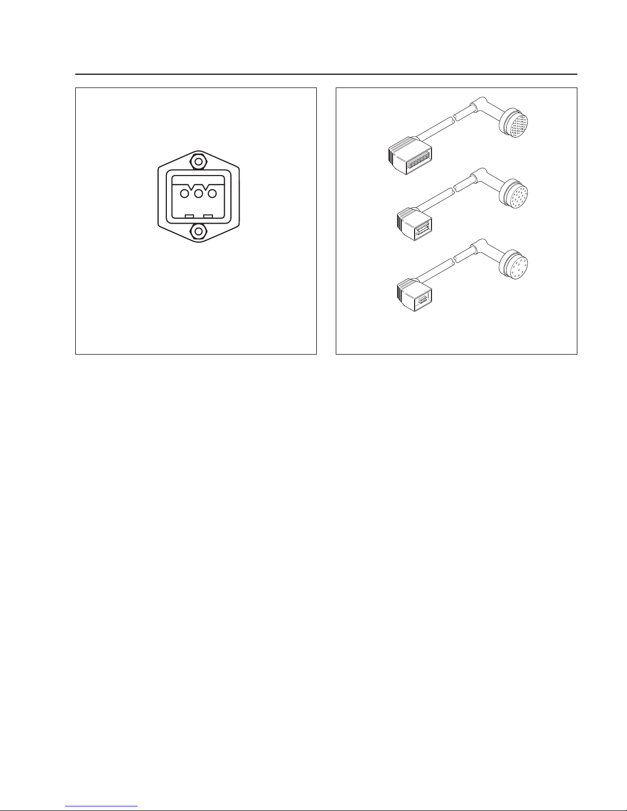
1 2 3
s
1 = Phase L
2 = Not assigned
3 = Neutral N
S = PE
Fig. 33 Connector assignment X10, supply connection
2.8.1 Power supply connection X10
The converter is ready to be connected to line supply
voltages between 200-240 V 50/60 Hz.The connection is
established using the power cable supplied, which is inserted at connector X10 at the rear of the converter.
Caution
The converter will be damaged if it is operated with the incorrect supply voltage.
BEARING
TMS
DRIVE
Fig. 34 Cable set with bended plugs;
cable set with straight plugs similar
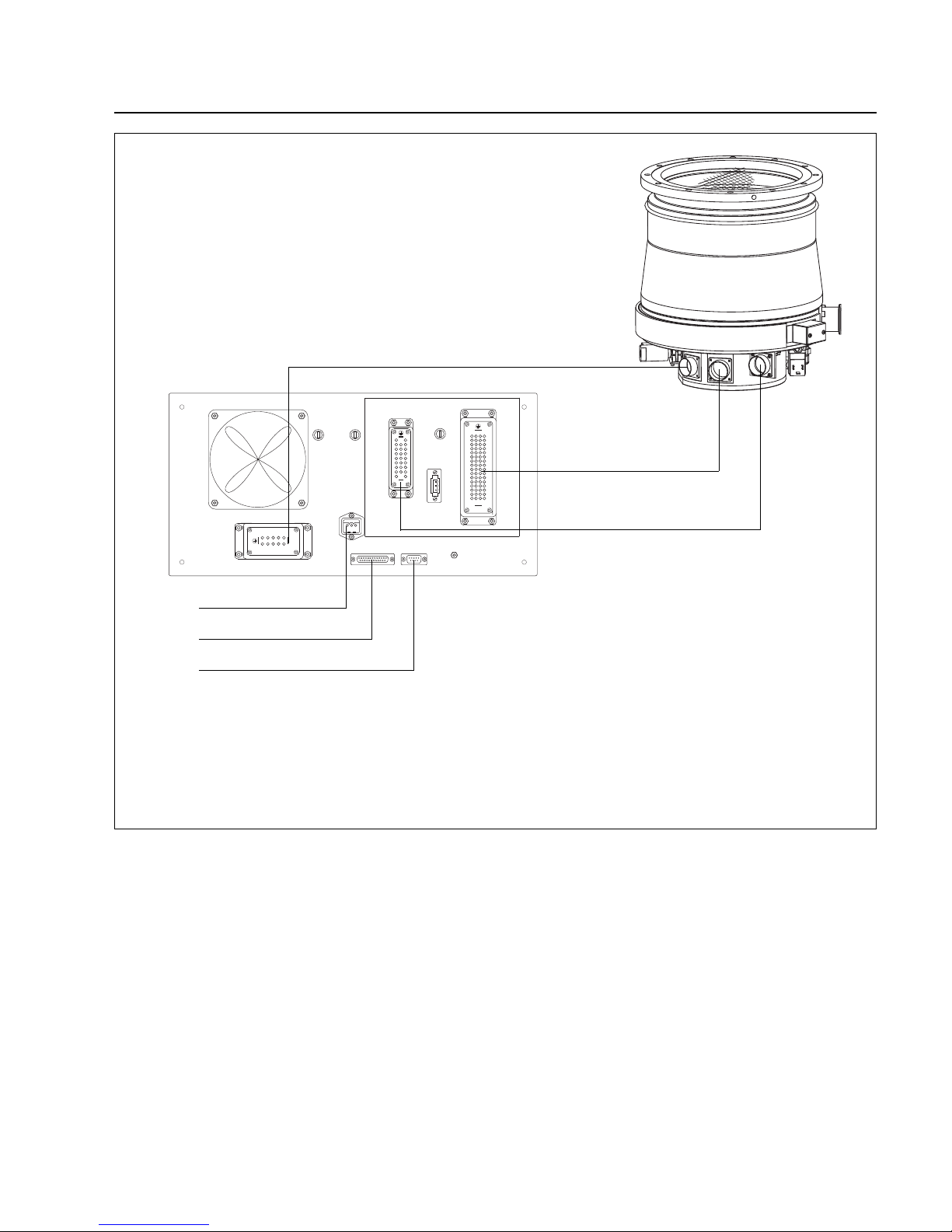
2.8.2 Pump connection
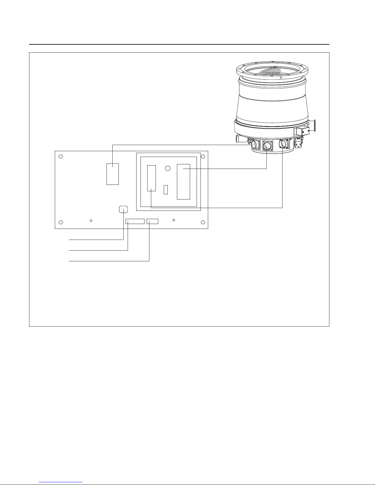
Connect the converter (X26) to the pump motor connection (X25) using the DRIVE connecting cable.
Connect the converter (X24) to the magnetic bearing
connection of the pump (X23) using the BEARING
connecting cable.
Connect the converter (X31) to the TMS connection of
the pump (X30) using the TMS connecting cable.
Also refer to Fig. 35 or 36.
Make sure that you have fixed all cables properly by
using the clamps fixed to the converter.
Mounting position and cable length
If the pump is mounted in a vertical position (intake
flange up or down) the permissible length of the pumpconverter cables is 3 to 20 meters.
If the pump is mounted in a horizontal position the permissible length of the pump-converter cables is 3 meter.
Page 34
Installation
34
GA 05.130/3.02 - 05/98
TMS
BEARING
DRIVE
X 24
BEAR-
ING
X 31
TMS
X 26
DRIVE
X 33
External
valve
F3
TMS Fuse
X 10
Mains plug
X 1 X 7.2
Control plug RS 232
PE
PE
MAINS
ANALOG INTERFACE
INTERFACE
Fig. 35 Block wiring diagram for MAG.DRIVE L
X25
X23
X30
Page 35
Installation
35
GA 05.130/3.02 - 05/98
X1
X7.2
X26
X31
F3
PE
1
13
14
25
1
ABCD
2
3
4
5
6
7
8
9
10
11
12
13
14
15
16
ABCD
1
2
3
4
5
6
7
8
9
10
11
12
13
14
15
16
X24
1
2
3
4
5
6
7
8
9
1
2
3
4
5
6
7
8
9
CBA
1
5
6
9
X10
1
3
1 2 3
s
F1F2
X33
4
5
9
3
2
1
10
8
7
6
X7.2
PE
X1
X33
F3
X24
F1
X31
F2
X26
X10
Fig. 36 Block wiring diagram for MAG.DRIVE L2
X25
X23
X30
MAINS
ANALOG INTERFACE
INTERFACE
TMS
BEARING
DRIVE
Page 36
Installation
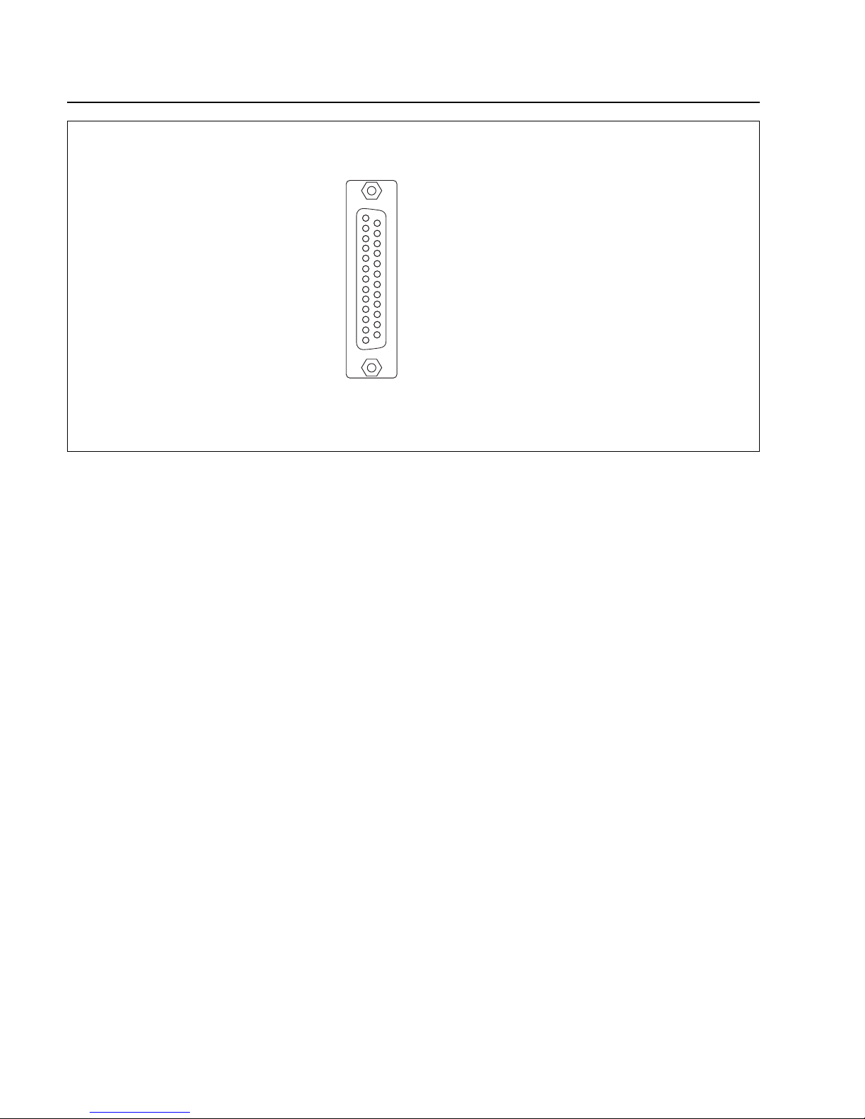
2.8.3 Control plug X1
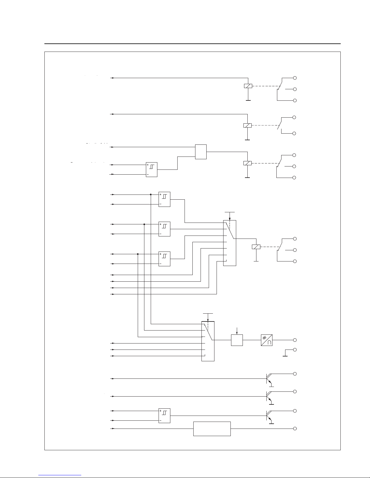
Relay outputs
The MAG.DRIVE L converter has 4 relay outputs.Three
relay outputs are permanently assigned a signal.
Normal operation (changeover contact)
Failure (changeover contact)
Warning (NO contact)
The option relay (changeover contact) can output one of
the following signals:
Threshold motor temperature reached
(only MAG.DRIVE L)
Threshold bearing temperature reached
(only MAG.DRIVE L2)
Threshold motor current reached
Threshold frequency reached
No cooling water
No purge gas
TMS temperature OK
Vent
The selection of signals for the option relay and the
adjustment of their thresholds can be achieved via the
operator control menu; see Sections 4.5.2 or 4.6.2.
Signaling outputs
Open-collector outputs are available to signal
start command applied
power supply O.K.
pump standstill
at control plug X1. The outputs can have a maximum
load of 15 V DC, 80 mA.
Analog output
The converter has an analog output which provides an
analog signal (0..10 V) with a 10-bit resolution.The analog output function can be alternatively used to output
motor current
actual frequency
motor temperature
rotor displacement signals (PW24, PV13, PZ12)
The output value can be increased or reduced by a scaling factor; refer to the operator control menu “Scaling”;
see Sections 4.5.2 and 4.6.2 Settings Converter.
36
GA 05.130/3.02 - 05/98
1
13
14
25
1 Remote/Local
2 Start/Stop
3 Ground
4 Analog output 0..10V
5 Analog ground
6 Relay „Failure“ com.
7 Relay „Failure“ n.c.
8 Relay „Failure“ n.o.
9 Relay „Norm. operation“ com.
10 Relay „Norm. operation“ n.o.
11 Relay „Norm. operation“ n.c.
12 Option relay com
13 Option relay n.o.
14 Option relay n.c.
15 Signal „Star t command present“
16 Signal „Power supply o.k.“
17 Output +15 V;max 80 mA
18 Signal „Pump stands still“
19 Digital input: TMS OFF
20 Digital input: Purge gas OFF
21 Relay „Warning“ n.o.
22 Relay „Warning“ com.
23 Digital input: Vent
24 Analog input 2
25 Analog input 1
n.o.= normally open
com. = common
n.c. = normally closed
Fig. 37 Assignment control plug X1
Page 37
Installation
37
GA 05.130/3.02 - 05/98
X1.6
X1.
8
X1.
7
X1.9
X1.10
X1.11
0
1
2
X1.12
X1.13
X1.14
X
X1.4
X1.5
X1.15
X1.16
X1.17
+15 V
3
4
5
&
X1.22
X1.21
X1.18
2,5 Hz
6
0
1
2
4
5
6
Strombegrenzung
80 mA
Open collector Ausgänge
Keine Störung
Relais Normalbetrieb
Normalbetrieb
Melderelais Option
Funktion
Melderelais
Funktion
Analogausgang
Analogausgang
Analog Masse
Startbefehl steht an
Stromversorgungo.k.
Skalierung
Kein Kühlwasser
Kein Sperrgas
TMS o.k.
Startbefehl
steht an
Relais Warnung
Warnung
Pumpe steht
Schwellwert
Motorstrom
Schwellwert
Motorstrom
Schwellwert
Frequenz
Frequenz-Istwert
Aktuelle Lager-Temp.
Schwellwert
Lager-Temp.
Frequenz-Istwert
Fluten
Rotorlage
Istwert PVW 13
Istwert PZ 12
Istwert PVW 24
Relais Störung
Frequenz-Istwert
Fig. 38 Function diagram outputs
Relay failure
Relay warning
Relay normal operation
Relay option
Function
relay option
Function
analog output
Scale
Analog output
Analog ground
Open collector outputs
Pump standstill
Current limit
80 mA
No failure
Warning
Start command
applied
Actual frequency
Normal operation
Motor or bearing
temperature
Threshold
Motor current
Threshold
Actual frequency
Threshold
No cooling water
No purge gas
TMS temperature ok
Vent
Rotor displacement
actual PVW 13
actual PVW 24
actual PZ12
Start command applied
Power supply
Actual frequency
Page 38
Installation
38
GA 05.130/3.02 - 05/98
Analog inputs
The converter has two analog inputs with a 10-bit resolution.
Input signal: 0...10V standard
4...20mA on request
A supplementary function can be set for analog input 2
via the operator control menu; see Sections 4.5.2 or
4.6.2:
No function: The input signal can be output via
the serial interface.
Frequency setpoint: In addition to the function descr i-
bed above, the drive frequency setpoint is entered via analog input 2.
Analog ground
Analog ground X1.5 is the reference ground for the analog output as well as for the analog inputs.
Digital inputs
The converter has 3 digital inputs with the following functions:
TMS OFF
Purge gas OFF
Vent ON
The functions are active if an High signal (15 V) is
connected at the digital input.
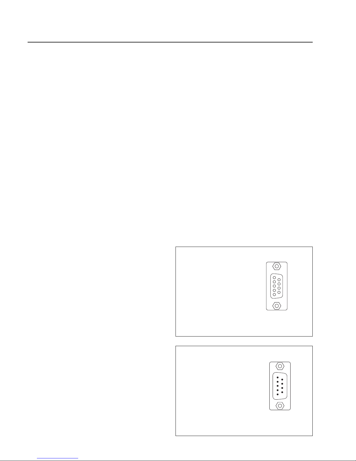
2.8.4 Interface connector
A 9-pin sub-D socket is provided at the front panel and a
9-pin sub-D connector at the rear panel to connect a higher-level open-loop control and monitoring unit or a PC
with the MAG.WIN operator control program.
The front connector X7.1 is assigned the serial interface
RS232. If the front connector is to be used, to select
connector X7.1, pin 1 must be connected to pin 5 (signal
ground). To upload the software, pin 4 (boot) must be
connected with pin 5 (signal ground).
The rear connector X7.2 is assigned with the serial
RS232 interface.
Further information on the serial interface and the interface protocol to be used are provided in the optional
manual „Serial interface MAG.DRIVE”.
1
5
6
9
1
5
6
9
1 Select front connector
X7.1
2 TxD
3 RxD
4 Boot
5 Signal ground
Fig. 39 Connector assignment,
interface X7.1 (front side)
Fig. 40 Connector assignment, interface X7.2 (rear side)
5 Signal ground
4 +5V output through 390 Ω
3 RS232 RxD
2 RS232 TxD
1 -
Page 39
Installation
39
GA 05.130/3.02 - 05/98
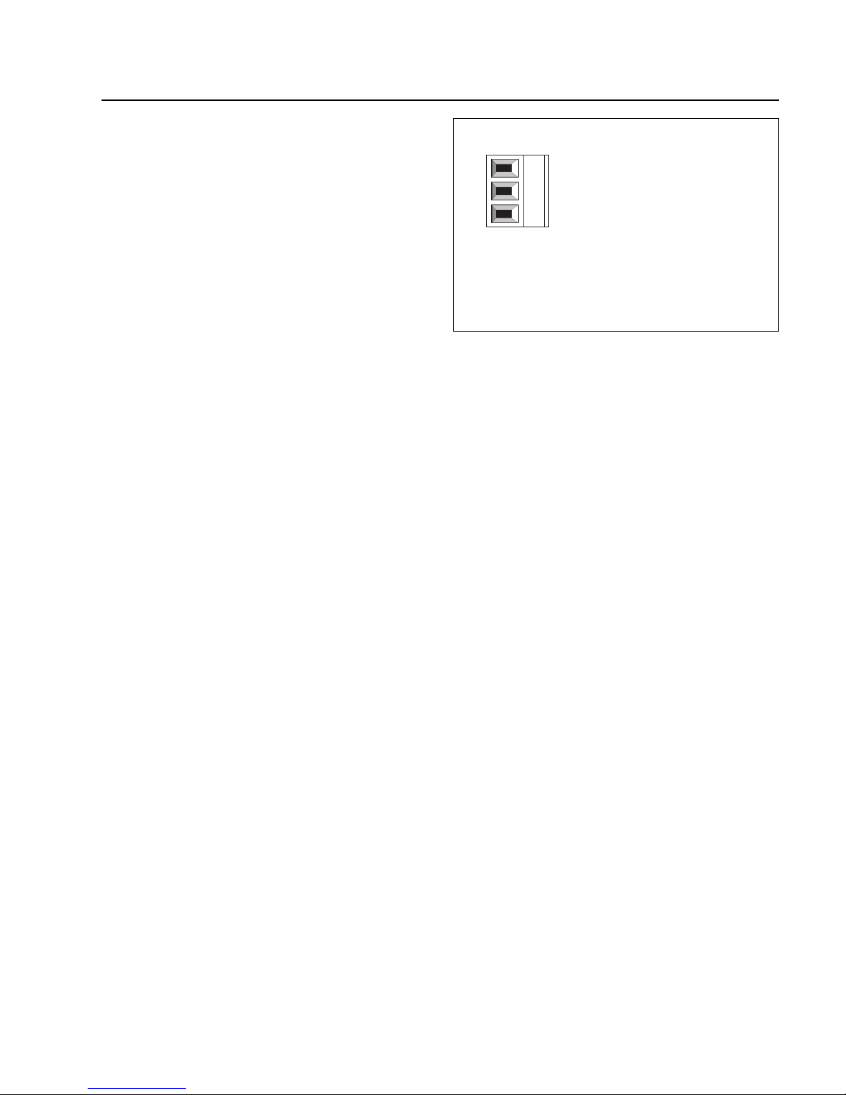
3 2 1
1 PE
2 + 24 V output,
max. 300 mA
3 Ground
Fig. 41 Connector assignment X33, supply voltage
2.8.5 Connection X33
The internal +24 V supply voltage can be accessed for
external loads at connector X33; for example, to connect
relays or solenoid valv es.The output is short-circuit-proof
and the output current is limited to 300 mA.
Page 40

Operation
40
GA 05.130/3.02 - 05/98
3 Operation
This Section describes the normal operation of the MAG
pumping system
• via the front panel keys START and STOP,
• with pump and converter in the state of delivery from
Leybold, and
• if no failure occurs.
If you want to operate the pumping system differently or
if you want more background information about the pumping system operation refer to the following Sections:
• Explanation of the front panel keys 4.1
• Explanation of the display 4.2
• Operate the pump via remote control 4.3
• Explanation of the displayed operating
statuses 4.4
• Change pump parameters via
the operating menu 4.5 or 4.6
• Explanation of the temperature
management system 4.7
• A failure message is displayed 6
3.1 Switching on
• Switch on the MAG.DRIVE.The display reads
Ready
0.0 A 0 Hz
If the pump has the optional TMS (including e.g.the red
heater band) the heater will be activated. The setpoint
temperature will be reached within 30 - 60 minutes
depending on cooling water temperature and flow.
In case of corresponding connection the backing pump
will be activated when switching on the MAG.DRIVE.
• Open the purge gas supply.
• Open the cooling water supply.
• Press the START button.
The pump runs-up.
Acceleration
20.0 A 250 Hz
is diplayed until the frequency setpoint has been reached. Then
Normal Operation
1.0 A 480 Hz
is displayed.
The backing pump and the MAG can be switched on
simultaneously. In such a situation the MAG serves from
the very outset as an effective baffle.
Do not suddenly expose the MAG to an already evacuated vacuum chamber .The pressure surge may cause the
rotor to make contact with the touch-down bearings.This
will cause increased wear.
The pump may make noise during the run-up and rundown phases.This has neither an influence on the pump
nor on the process.
Page 41
Operation
3.2 Operation
The magnetic bearing in the MAG are immune to wear.
In addition to the magnetic bearings, the MAG is equipped with touch-down bearings which protect the rotor
against mechanical contact with the stator if the pump is
subjected to external shock loading or when the pump is
switched off.These touch-down bearings have a limited
service life. Please observe the following in order to
obtain maximum service life.
• Avoid shock and vibrations when the pump is running. Shocks perpendicular to the rotation axis are
particularly har mful. If the pump appears to be running in the mechanical bearings continuously it is
switched off.
• Avoid frequent run up and down. The converter may
overheat. You may run up und down the pump twice
immediately after each other.
• Do not disconnect the MAG and MAG.DRIVE while
they are operating. If MAG and MAG.DRIVE have
been disconnected accidently do not re-connect them
while the MAG is operating.
Warning
Monitor the purge gas continuously.
Insufficient purge gas flow can result in:
- Process gases entering the motor and
bearing area of the MAG
- Process gases escaping from the purge
gas valve
- Humidity entering the pump.
Refer to Section 2.7.
MAG with heating collar:
Warning
The heating collar will be hot during operation. Burn hazard!
3.3 Switching off
The MAG.DRIVE controls the venting automatically provided purge gas is connected to the MAG and the
MAG.DRIVE is programmed correspondingly („Vent on“).
Caution
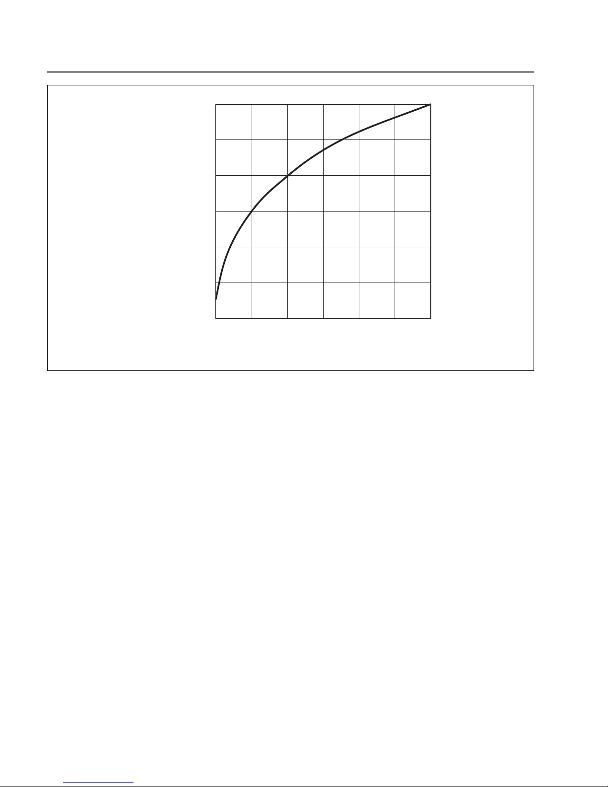
The values shown in the pressure rise
curve must be maintained; see Fig. 42.
Caution
Do not stop the MAG with the mains. Use
the STOP key.
Switching off the mains while the pump is
running will wear out the touch down
bearings.
• Press the STOP key.
Deceleration
20.0 A 400 Hz
will be displayed.When the display reads
Ready
0.0 A 0 Hz
the pump has come to a standstill.
• Close the cooling water supply when the pump is
switched off in order to a v oid condensate formation in
the pump.
The backing pump may be switched off once the MAG
has stopped.
If the MAG has been used for pumping corrosive gases
it should be purged with dry nitrogen for one hour before
switching off.During down times of the system take care
that neither ambient air nor cleaning agents enter the
pump.
41
GA 05.130/3.02 - 05/98
Page 42
Operation
42
GA 05.130/3.02 - 05/98
10
3
Forevacuum pressure/mbar
10
2
10
1
10
0
10
-1
10
-2
10
-3
Fig. 42 Curve for safe venting of the MAG;
pressure rise as a function of venting time
0 10 20 30 40 50 60
Time/s
Page 43
4 Converter Control
4.1 Functions of the front
panel keys
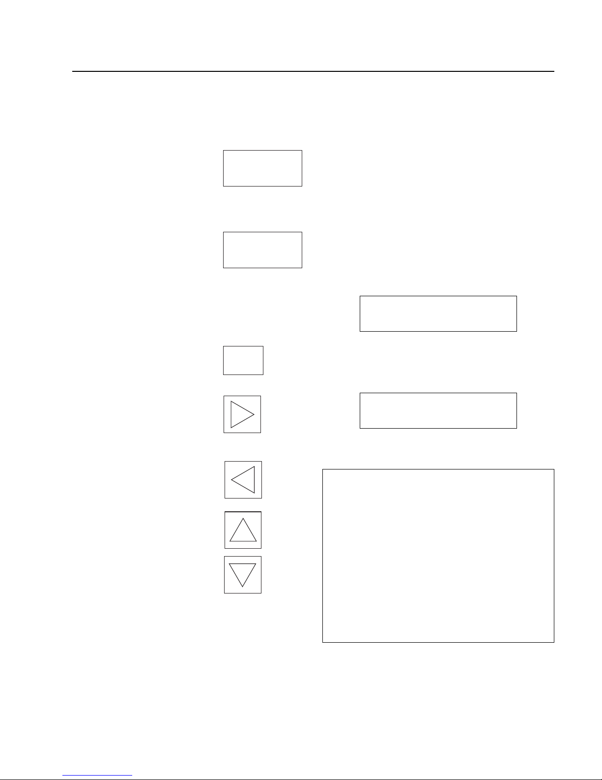
• Starts the pump (only possible
if there is no fault).The start key
is only active if the user is in the
basic menu or in the operating
display.
• Returns to the operating display
from any point in the programming menu.
• Stop when the pump is opera-
tional. The pump is braked
down to < 1 Hz.
• Acknowledges a failure after the
cause of the failure has been
removed.
• Selects a sub-menu
• Acknowledges a modified value
• Changes from the operating
display into the programming
menu
• Selects the programming menu
in the main menu
• Returns to the last main menu
in the programming menu
• Increases a parameter value or
proceeds to the next option
• Lowers a parameter value or
returns to the previous option
GA 05.130/3.02 - 05/98
Converter Control
43
4.2 Operating display
All operating states, warning and failure are displa y ed on
the display and three lamps on the front side of the converter.
If a critical operating status occurs, e.g. “Warning Temp.
Pump”, this warning is displayed, alternating with the
operating display.
Plain text display
1st line: Operating status
2nd line: Motor current / Actual frequency /
(TMS status code for MAG.DRIVE L2)
or
1st line: Failure message
2nd line: Failure cause
TMS status code (only for MAG.DRIVE L2)
No. Code Descr iption
————————————————————————
1 H Heating pump (range below T
set
- 5K)
2 H O K Temp.TMS ok, heater ON
(range T
set
- 5K to T
set
)
3 O K Temp.TMS ok (range T
set
± 2K)
4 C O K Temp.TMS ok, cooling ON
(range T
set
+ 5K to T
set
)
5 W Warning Temp. TMS
(Temp. > T
set
+ 5K)
O F F TMS cancelled via control plug X1
see also Section 4.7.2 „TMS for the MAG.DRIVE L2“
Failure
Accel.Time
Acceleration
9.7 A 254 Hz
START
STOP
ENTER
Page 44
Converter Control
Significance of the lamps
COM (green)
Is lit if communication has been established via the interface.
STA TUS(green/red)
Red, steady light = Failure
Red, flashing = Warning
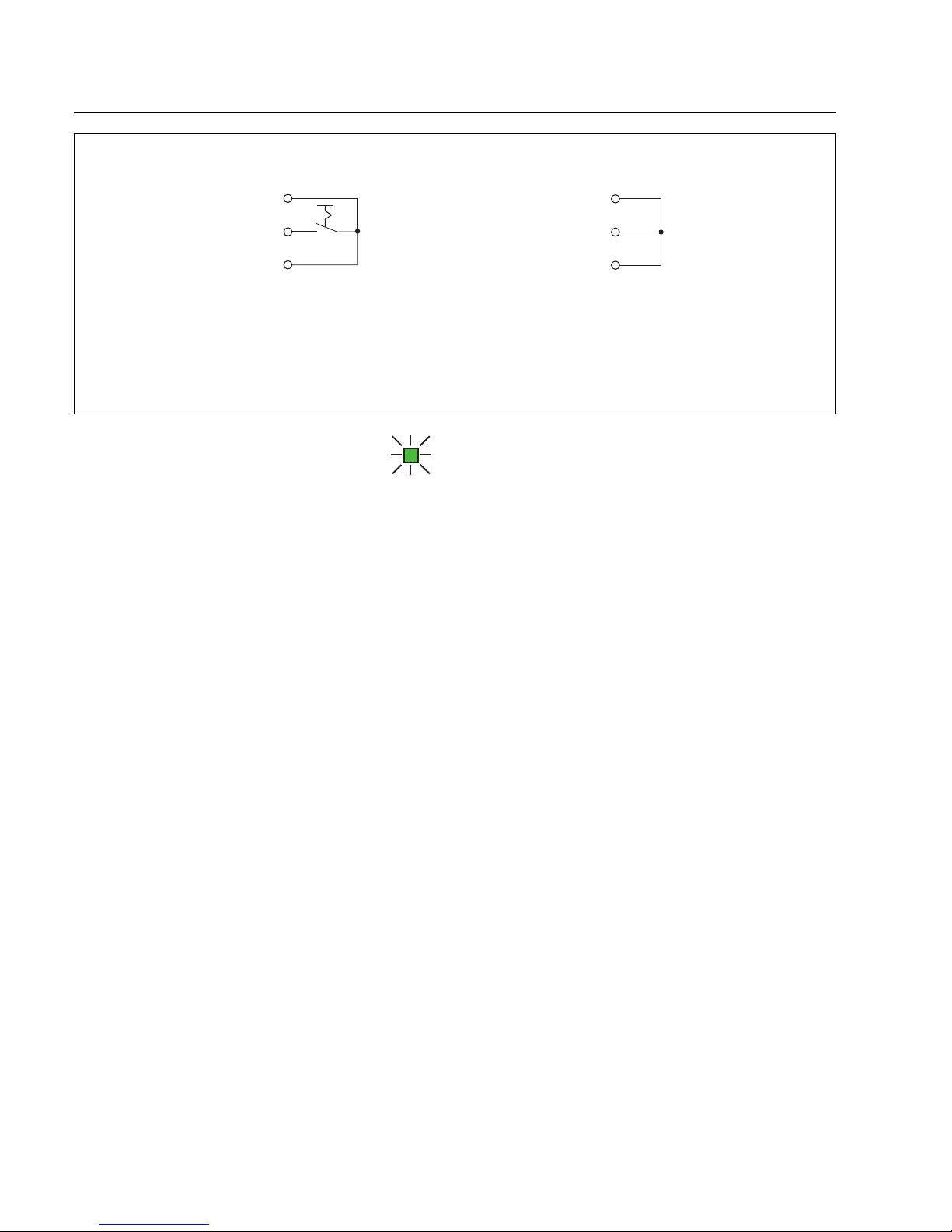
Green, flashing (slow) = Start delay, Acceleration
Green, flashing (fast) = Deceleration,
Kinetic buffering
Green, steady light = Nor mal operation
MAINS (green)
This lamp is lit if the power is switched-on, and all of the
supply voltages for operation are available.
Flashes when the power fails as long as the power supply voltages in the converter are maintained by the kinetic buffering.
4.3 Remote control
The converter permits 3 operating modes. They can be
selected via contact X1.1 of the control connector at the
rear panel of the converter or via the serial interface.
Operating mode 0 is automatically selected after the line
supply voltage has been applied.
Operating mode 0
The pump can be switched-on or off using the START/
STOP keys or via control connector X1. The reference
frequency can be selected in the operating menu.
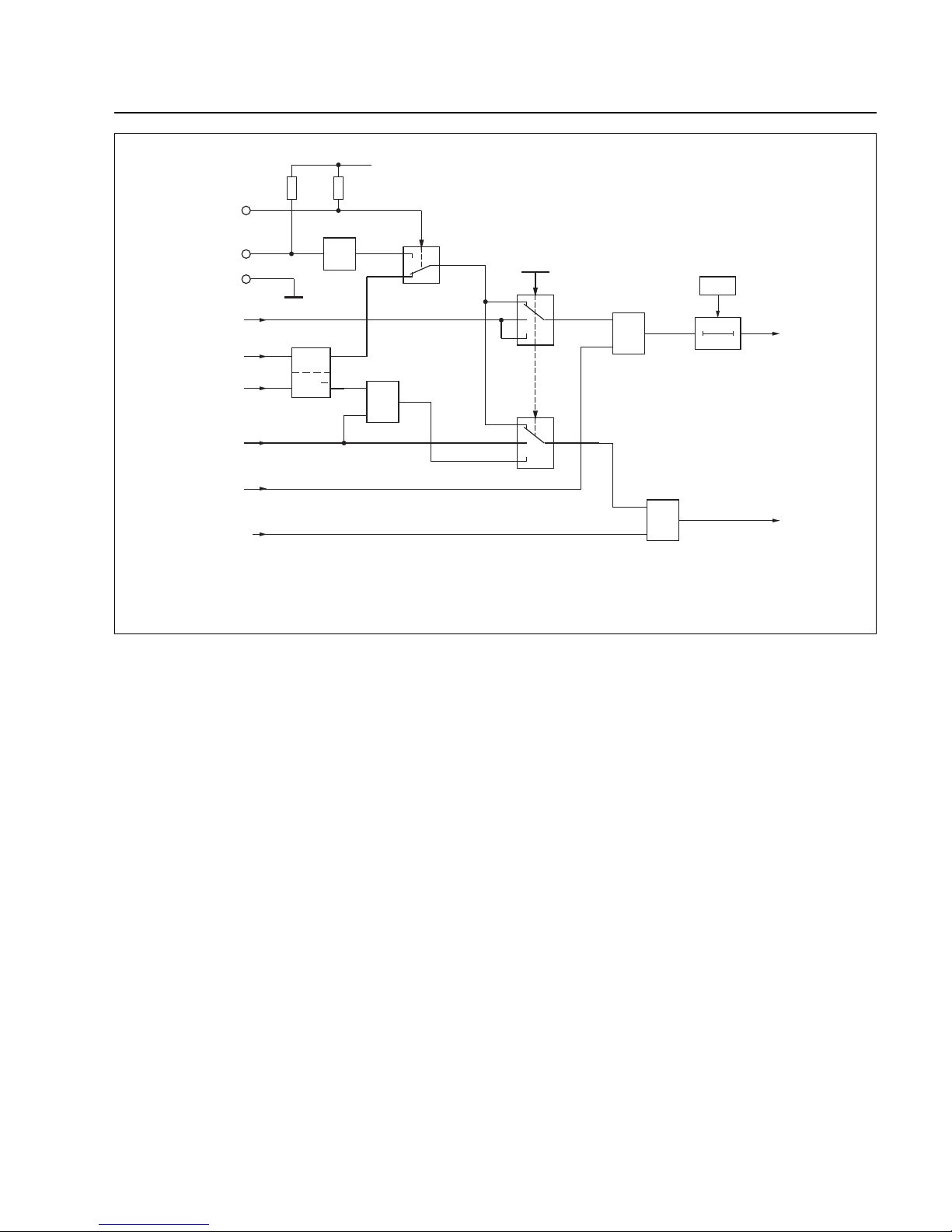
• X1.1 not connected = Start/Stop via the operator control panel
• Jumper X1.1-X1.3 = Start/Stop via control input X1.2
Operating mode 1
This operating mode can only be selected via the serial
interface.
The pump can only be started and stopped via the serial interface.
The frequency setpoint can only be changed via the serial interface, e.g.from MAG.WIN
44
GA 05.130/3.02 - 05/98
Remote
Start
Masse
X1.1
X1.2
X1.3
Switch closed: START
Switch open: STOP
Remote
Start
Masse
X1.1
X1.2
X1.3
Autostart
Remote
Start
Ground
Remote
Start
Ground
Fig. 43 Connecting-up example remote control
Page 45
Converter Control
Operating mode 2
This operating mode can only be set via the serial interface.
The pump can be switched-off via the keyboard, but it
cannot be started via the keyboard.
The frequency setpoint can only be changed via the serial interface, e.g.from MAG.WIN.
Automatic starting after the power has been
connected
Connect contacts X1.1, X1.2 and X1.3 with one another.
The converter starts automatically when the power is
applied.
45
GA 05.130/3.02 - 05/98
0
1
0
1
2
S
R
Q
Q
&
s
0
1
2
START
REMOTE
+15 V
X1.1
X1.2
X1.3
START
Pumpe
STOP
Pumpe
START
Bedienfeld
STOP
Bedienfeld
STOP
Schnittstelle
START
Schnittstelle
Störungen, die
Bremsbetrieb
verursachen
0 V = 0
15 V = 1
10 K
Ω
Keine
Störung
≥1
≥1
Startverzögerungszeit
P36
P12
-1
(Bremsbetrieb mit
dem Pulswiderstand)
Betriebsart:
Programmierung nur
über Schnittstelle
Fig. 44 Function diagram START/STOP
Operating mode:
Programming only via
serial interface
Start delay time
START
pump
STOP
pump
decelerating the pump
with the pulsed resistor
START serial
interface
START
key pad
STOP
key pad
STOP serial
interface
No
failure
Failures
causing
deceleration
Page 46

Converter Control
46
GA 05.130/3.02 - 05/98
4.4 Operating statuses
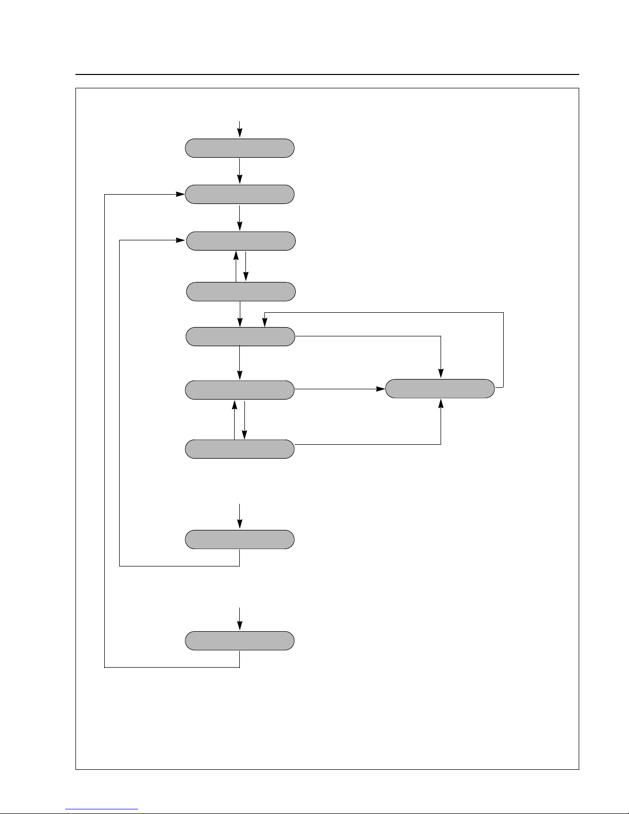
Switch-On Guard
The converter goes into the “Switch On Guard”operating
status after the power is switched on and after initialization. If there is no warning or failure, it changes over into
the “Ready” condition.
After a failure has been acknowledged, the converter
goes into the “Switch On Guard” operating status. The
failure must be acknowledged a second time, so that it
then goes into the “Ready” condition.
Ready
The converter is ready and waits for the START command. All parameters can be interrogated or changed via
the operator control panel or the serial interface.
The basic menu parameters (refer to 4.5/4.6, operating
menu) can be scanned via the operator control panel.
Acceleration
The pump continuously accelerates with the maximum
current. The acceleration time is monitored to ensure that
it lies within a programmed value (refer to the menu “settings pump/max. Accel. Time”). If the converter hasn’t
reached the normal operating mode during the monitoring time, then it is shutdown with the failure message
„max. Accel. Time”.
Normal operation
After a programmable frequency threshold has been reached (refer to the menu “settings pump/Normal Operation”), the converter goes into the normal operation mode
but the pump continues to accelerate up to the frequency setpoint.
Maximum power or Overload
„Maximum power“ for MAG.DRIVE L or
„Overload“ for MAG.DRIVE L2.
The speed is continuously monitored and controlled. If
the speed, even at maximum current, cannot be held at
the setpoint, as a result of external influences, e.g.
excessive gas intake, the speed reduces until the converter goes into the „max.pow er”or „Overload“ operating
condition when the programmable frequency threshold is
fallen below (refer to the menu “settings pump/Normal
Operation”). The acceleration time is restarted. If the
converter hasn’t gone into the normal operating mode
after the monitoring time, it is shutdown with the failure
message „max. power time” or „Failure Overload Time“.
Kinetic buffering
If the power fails when the converter is switched on, the
converter regenerates due to the pump up to a minimum
frequency of < 170 Hz. When the power returns, the
pump is again accelerated up to the frequency setpoint.
The acceleration time is now restarted. If the converter
hasn’t gone into the normal operating mode after the
monitoring time, it is shutdown with the failure message
„max. Accel.Time” .
Deceleration
After a stop command, the pump is braked down to a
speed < 1 Hz as quickly as possible. A brake resistor is
integrated into the converter which converts the regenerative energy into heat.
Failure
The converter was shutdown with a failure message and
waits for a failure acknowledgement after the failure has
been removed.The failure type can be read from the display. The failure message can be acknowledged by
depressing the STOP key or via the serial interface.
Page 47
Converter Control
47
GA 05.130/3.02 - 05/98
Mains switched on
Initialization
Switch On Guard
Acceleration
Normal Operation
Kinetic Buffer
Maximum Power
or Overload
Deceleration
Failure
After a failure, quit a second time
START command
Mains ok
Frequency > P 25 x P24
Mains failure
Mains failure
Frequency > P25 x P24
Frequency < P25 x P24
Mains failure
STOP command
If a failure occurs
the pump is decelerated
Frequency < 1 Hz
Failure occurs
Failure acknowledgement
only possible if f<5 Hz
Ready
Start Delay
STOP command
Parameter:
P24 = Frequency setpoint
P25 = Factor normal operation
Fig 45 Diagram: Operation status
Page 48
Converter Control MAG.DRIVE L
48
GA 05.130/3.02 - 05/98
Ready
0.0 A 0 Hz
Enter
Setpoint
480 Hz
Enter
Pump life
0.00 h
Enter
Temp. Motor
50 °C
Enter
Temp. Converter
40 °C
Enter
Temp. Pump
50 °C
Enter
actual PVW 13
10%
Enter
actual PVW 24
10%
Enter
actual PZ 12
5%
Enter
power
400 W
Enter
Not active
Temp.TCU
63 °C
Enter
Not active
Temp. Cooling
20 °C
Enter
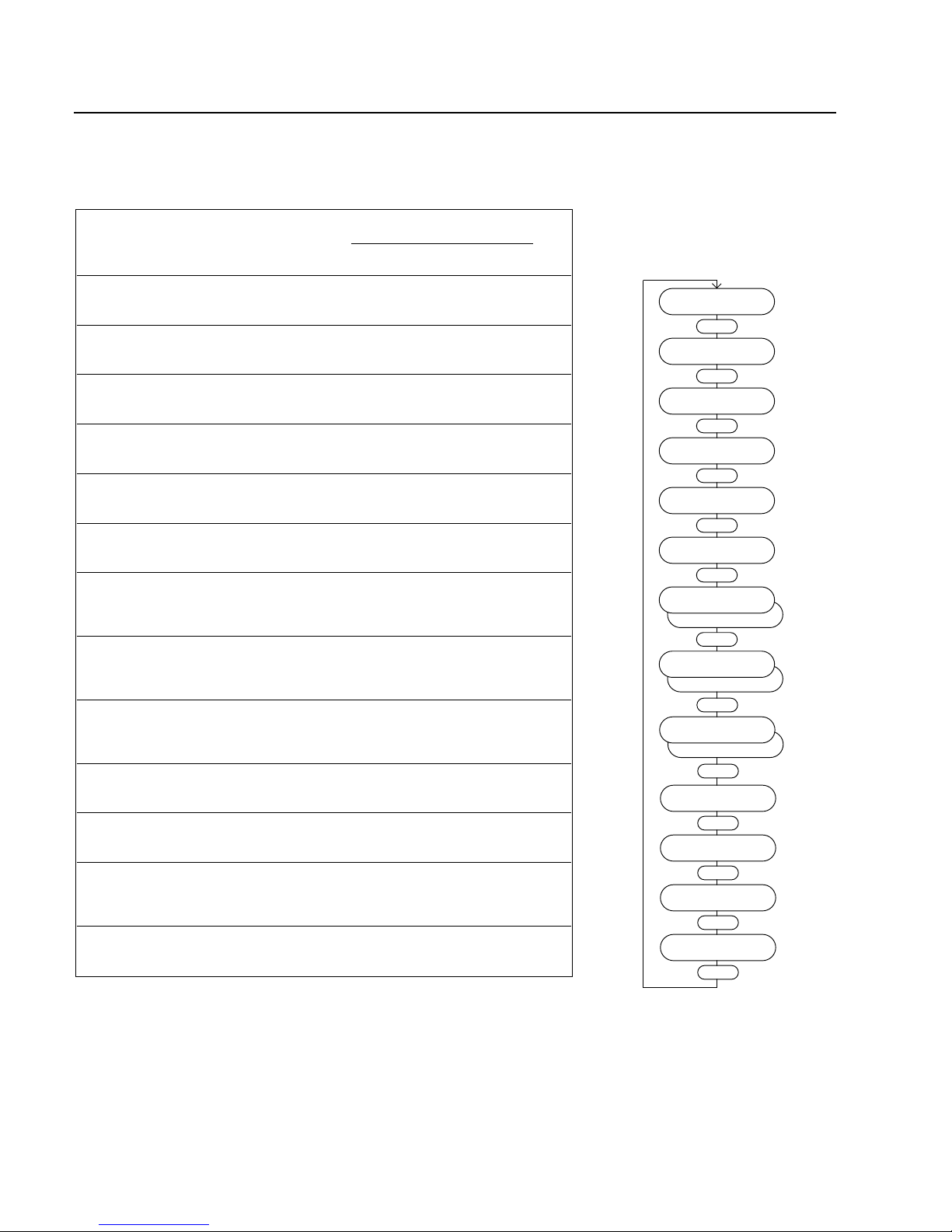
4.5.1 Basic menu
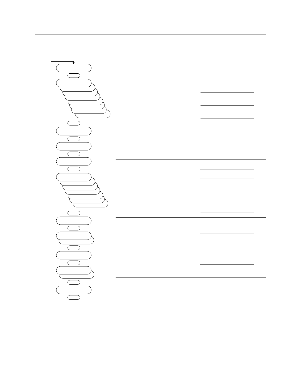
Menu item Description Adjustable value / option Ac-
cess
min. max. stan- Unit
value value dard
Ready Operating display - - - - -
Setpoint Sets the speed for operation 0 480 480 Hz r/w
Pump life Total operating hours of the pump actual value h r
Temp.Motor Motor temperature actual value °C r
Temp.Converter Temperature of the power actual value °C r
electronic
Temp.Pump Temperature of the magnetic actual value °C r
bearing
Temp.TCU Temperature of the Temperature actual value °C r
Management System
Temp.Cooling Cooling water temperature actual value °C r
Diff. pressure Difference pressure actual value mbar r
Only active at pump models
with purge valve flow control
(MCF, MCTF)
actual PVW 13 Rotor displacement in the
magnetic bearing actual value % r
plane VW13
actual PVW 24 Rotor displacement in the
magnetic bearing actual value % r
plane VW24
actual PZ 12 Rotor displacement in the
magnetic bearing actual value % r
axis Z12
power Power consumption of the drive actual value W r
r (read) = value can only be read
r /w (read/write) = value can be read and written
Enter
Not active
Diff. pressure
100 mbar
4.5 Operating menu for the MAG.DRIVE L
Page 49
Converter Control MAG.DRIVE L
49
GA 05.130/3.02 - 05/98
inductance ...
analog 1 4%
German
4.5.2 Settings converter
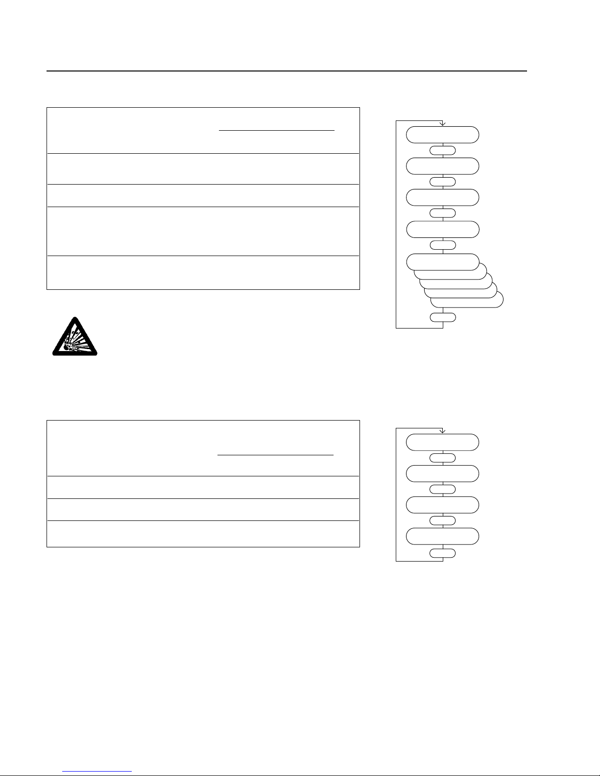
Menu item Description Adjustable value / option Ac-
cess
min. max. stan- Unit
value value dard
Option Relay Relay with change -over Threshold motor
contact; the operator can temperature reached °C r/w
select one of the functions Threshold motor
described current reached A
Threshold frequency
the thresholds are adjusted reached Hz
in the next three menu items No cooling water -
no purge gas -
TMS temperature o.k. -
Vent -
„analog1 4%“ not used
Threshold Threshold motor temp. 0 100 60 °C r/w
for option relay
Threshold Threshold motor current 0 20 10 A r/w
for option relay
Threshold Threshold frequency 0 480 300 Hz r/w
for option relay
analog output Analog output 0...10V; Motor current;
the operator can select 20 A =10Vxscale factor V r/w
one of the functions Act.frequency ;
described 500 Hz = 10Vxscale factorV
Bearing temp.;
100 °C = 10Vxscale factor V
Actual PVW13;
100% = 10Vxscale factor V
Actual PVW24;
100% = 10Vxscale factor V
Actual PZ12;
100% = 10Vxscale factor V
„inductance“ not used
scale factor Scale factor for the analog output 0 2 1 - r/w
Analog Input 2 Analog input 0...10V ; No function - r/w
optionally frequency setpoint
via analog input 2 Function frequency
(10V = max. frequency setpoint) setpoint -
Start delay Waiting time between start
command and acceleration 0 1200 0 s r/w
Display Display language English - r/w
German -
Bus adress Bus adress for the converter for
operation via 0 31 0 - r/w
serial interface RS232
venting
Temp.TCU ok
no purge gas
no cooling water
frequency
Converter data
Enter
current
option relay
temperature
Enter
Threshold
60 °C
Enter
Threshold
10.0 A
Enter
Threshold
300 Hz
Enter
PZ12 peak
PVW24 peak
PVW13 peak
temperature
frequency
analog output
current
Enter
scale factor
1.0 x
Enter
freq. setpoint
Analog Input 2
no function
Enter
Start delay
0 s
Enter
Display
English
Enter
Bus address
0
Enter
r (read) = value can only be read
r /w (read/write) = value can be read and written
Page 50
Converter Control MAG.DRIVE L
50
GA 05.130/3.02 - 05/98
4.5.3 Settings pump
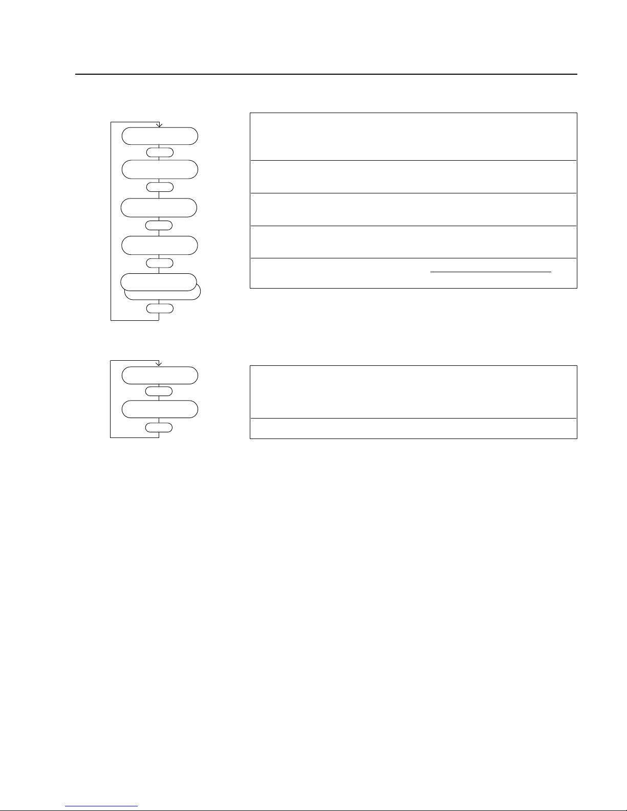
Menu item Description Adjustable value / option Ac-
cess
min. max. stan- Unit
value value dard
Normal operation Threshold for normal operation
corresponding to the 35 99 95 % r/w
frequency setpoint
max. accel.time Monitor time for acceleration
and overload 600 3600 1000 s r/w
Motor current Limits the maximum motor
current; used to limit the 5 100 65 % r/w
pump rotor temperature.
!!! See warning below!!!
Pump Type Displays the installed pump type Installed pump type - r/w
!!! Do not change
the pump setting!!!
Warning
Setting the motor current to more than 65% may result in rotor
overheating.
Setting the motor current to more than 65% or changing the
pump setting without permission from Leybold voids the warranty.
4.5.4 Settings active magnetic bearing
Menu item Description Adjustable value / option Ac-
cess
min. max. stan- Unit
value value dard
ident.magn.bear. Code to identify AMB type actual value - r
Emerg. bearing Counts actual value - r
Emerg. bearing Time actual value s r
Prog.Pump
Enter
Normal operation
95 %
Enter
max. accel. time
800 s
Enter
r (read) = value can only be read
r /w (read/write) = value can be read and written
Magnetic bearing
Enter
ident.magn.bear.
7
Enter
Emerg. bearing
0
Enter
Emerg. bearing
0.0 s
Enter
Motor current
65%
Enter
MCFT
MCF
M
MC
Pump Type
MCT
Enter
Page 51
Converter Control MAG.DRIVE L
51
GA 05.130/3.02 - 05/98
4.5.5 Settings temperature management system
Menu item Description Adjustable value / option Ac-
cess
min. max. stan- Unit
value value dard
Setpoint Temp. Setpoint Temperature 20 75 63 °C r/w
Management System
Warn.Temp. TCU Warning temperature
Temperature Management 0 85 70 °C r/w
System
FailTemp.TCU Shutdown temperature
Temperature Management 0 100 72 °C r/w
System
speaker Intermittent = warning off - r/w
Continuous = failure on -
4.5.6 Settings purge / vent
Menu item Description Adjustable value / option Ac-
cess
min. max. stan- Unit
value value dard
P-Nr.HE Testdis Not used
TCU
Enter
Setpoint Temp
63 °C
Enter
Purge/Vent
Enter
P-Nr.HE-Testdis
0
Enter
r (read) = value can only be read
r /w (read/write) = value can be read and written
Warn.Temp.TCU
70 °C
Enter
Fail Temp.TCU
72 °C
Enter
on
speaker
off
Enter
Page 52
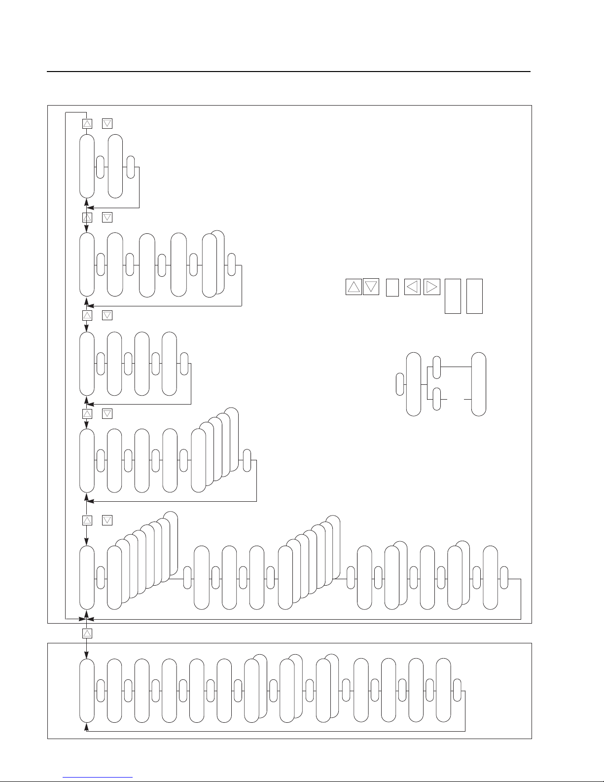
Converter Control MAG.DRIVE L
52
GA 05.130/3.02 - 05/98
4.5.7 Total view of the menu
Programming menu
Selects the parameterization menu from the
operating display.
Switches forward to the next main menu.
Switches back to the last main menu.
Selects submenu.
Confirms to store changed parameters.
Increases a parameter value or switches
forward to the next option.
Reduces a parameter value or switches
back to the last option.
Starts the pump. Only possible from the
basic menu.
Stops the pump.
Return to the operating display from
parameterization menu.
START
STOP
ENTER
Stop
Data to Eeprom?
Stop=no Enter=yes
Enter
Ready
00.0 A 0000 Hz
Stop
Data are stored
in the EPROM
To exit the parameterization menu
Basic menu
ororor
Ready
0.0 A 0 Hz
Enter
Setpoint
480 Hz
Enter
Pump life
0.00 h
Enter
Temp. Motor
50 °C
Enter
Temp. Converter
40 °C
Enter
Temp. Pump
50 °C
Enter
actual PVW 13
10%
Enter
actual PVW 24
10%
Enter
actual PZ 12
5%
Enter
power
400 W
Enter
Not active
Temp. TCU
63 °C
Enter
Not active
Temp. Cooling
20 °C
Enter
Enter
Not active
Diff. pressure
100 mbar
inductance ...
analog 1 4%
German
venting
Temp. TCU ok
no purge gas
no cooling water
frequency
Converter data
Enter
current
option relay
temperature
Enter
Threshold
60 °C
Enter
Threshold
10.0 A
Enter
Threshold
300 Hz
Enter
PZ12 peak
PVW24 peak
PVW13 peak
temperature
frequency
analog output
current
Enter
scale factor
1.0 x
Enter
freq. setpoint
Analog Input 2
no function
Enter
Start delay
0 s
Enter
Display
English
Enter
Bus address
0
Enter
Prog.Pump
Enter
Normal operation
95 %
Enter
max. accel. time
800 s
Enter
Motor current
65%
Enter
MCFT
MCF
M
MC
Pump Type
MCT
Enter
Magnetic bearing
Enter
ident.magn.bear.
7
Enter
Emerg. bearing
0
Enter
Emerg. bearing
0.0 s
Enter
TCU
Enter
Setpoint Temp
63 °C
Enter
Warn. Temp. TCU
70 °C
Enter
Fail Temp. TCU
72 °C
Enter
on
speaker
off
Enter
Purge/Vent
Enter
P-Nr. HE-Testdis
0
Enter
or or
Software version 1.2.3
Page 53
4.6.1 Basic menu
Menu item Description Adjustable value / option Ac-
cess
min. max. stan- Unit
value value dard
Ready Operating display - - - - -
Freq.Setpoint Sets the speed for operation 0 480 480 Hz r/w
Operation Hours Total operating hours of the pump actual value h r
Motor Temp. Motor temperature actual value °C r
Converter Temp. Temperature of the power actual value °C r
electronic
Bearing Temp. Temperature of the magnetic actual value °C r
bearing
Actual Value TMS Temperature of the Temperature actual value °C r
Management System
Cooling Temp. Cooling water temperature actual value °C r
Actual PVW 13 Rotor displacement in the
magnetic bearing actual value % r
plane VW13
Actual PVW 24 Rotor displacement in the
magnetic bearing actual value % r
plane VW24
Actual PZ 12 Rotor displacement in the
magnetic bearing actual value % r
axis Z12
Power Power consumption of the drive actual value W r
Software Version Actual software version actual value - r
Converter Control MAG.DRIVE L2
53
GA 05.130/3.02 - 05/98
Ready
0.0 A 0 Hz
Enter
Freq.Setpoint
480 Hz
Enter
Operation Hours
0.00 h
Enter
Motor Temp.
50 °C
Enter
Converter Temp.
40 °C
Enter
Bearing Temp.
50 °C
Enter
Actual PVW 13
10%
Enter
Actual PVW 24
10%
Enter
Actual PZ 12
5%
Enter
Power
400 W
Enter
Not Active
Actual Value TMS
63 °C
Enter
Not Active
Cooling Temp.
20 °C
Enter
r (read) = value can only be read
r /w (read/write) = value can be read and written
4.6 Operating menu for the MAG.DRIVE L2
Software Version
103.04
Enter
Page 54
Converter Control MAG.DRIVE L2
54
GA 05.130/3.02 - 05/98
r (read) = value can only be read
r /w (read/write) = value can be read and written
4.6.2 Settings converter
Menu item Description Adjustable value / option Ac-
cess
min. max. stan- Unit
value value dard
Option Relay Relay with change -over Threshold bearing
contact; the operator can temperature reached °C r/w
select one of the functions Threshold motor
described current reached A
Threshold frequency
the thresholds are adjusted reached Hz
in the next three menu items No cooling water -
no purge gas -
TMS temperature o.k. -
Vent -
Threshold Threshold bearing temp. 0 100 60 °C r/w
for option relay
Threshold Threshold motor current 0 20 10 A r/w
for option relay
Threshold Threshold frequency 0 480 300 Hz r/w
for option relay
Analog Output Analog output 0...10V; Motor current;
the operator can select 20 A =10Vxscale factor V r/w
one of the functions Act.frequency ;
described 500 Hz = 10Vxscale factorV
Bearing temp.;
100 °C = 10Vxscale factor V
Actual PVW13;
100% = 10Vxscale factor V
Actual PVW24;
100% = 10Vxscale factor V
Actual PZ12;
100% = 10Vxscale factor V
Scale Factor Scale factor for the analog output 0 2 1 - r/w
Analog Input 2 Analog input 0...10V ; No function - r/w
optionally frequency setpoint
via analog input 2 Function frequency
(10V = max. frequency setpoint) setpoint -
Start Delay Waiting time between start
command and acceleration 0 1200 0 s r/w
Display Display language English - r/w
German -
Bus Adress Bus adress for the converter by
operation via 0 31 0 - r/w
serial interface RS232/485
Acoustic Alarm OFF - r/w
Intermittent = warning ON Continuous = failure
German
Vent
TMS ok
No Purge gas
No Cooling Water
Frequency
Set Converter
Enter
Motor Current
Option Relay
Bearing Temp.
Enter
Threshold
60 °C
Enter
Threshold
10.0 A
Enter
Threshold
300 Hz
Enter
Actual PZ12
Actual PVW24
Actual PVW13
Bearing Temp.
Actual Frequency
Analog Output
Motor Current
Enter
Scale factor
1.0 x
Enter
Freq.Setpoint
Analog Input 2
No Function
Enter
Start delay
0 s
Enter
Display
English
Enter
Bus address
0
Enter
Acoustic Alarm
Off
Enter
Page 55
Converter Control MAG.DRIVE L2
55
GA 05.130/3.02 - 05/98
4.6.3 Settings pump
Menu item Description Adjustable value / option Ac-
cess
min. max. stan- Unit
value value dard
Normal Operation Threshold for normal operation
corresponding to the 35 99 95 % r/w
frequency setpoint
Max. Accel.Time Monitor time for acceleration
and overload 600 3600 1000 s r/w
Pump Type Displays the installed pump type Installed pump type - r
4.6.4 Settings temperature management system
Menu item Description Adjustable value / option Ac-
cess
min. max. stan- Unit
value value dard
TMS Setpoint Setpoint Temperature- 20 70 63 °C r/w
Management-System
Set Pump
Enter
Normal Operation
95 %
Enter
Max. Accel. time
800 s
Enter
Pump Type
MAG 1600/2000 CT
Enter
Set TMS
Enter
TMS Setpoint
60 °C
Enter
r (read) = value can only be read
r /w (read/write) = value can be read and written
Page 56
Converter Control MAG.DRIVE L2
56
GA 05.130/3.02 - 05/98
4.6.5 Settings purge / vent
Menu item Description Adjustable value / option Ac-
cess
min. max. stan- Unit
value value dard
Purge / Vent The operator can select one Purge OFF - r/w
of the beside standing Purge ON options for purge and vent Controlling purge / vent
via control plug X1 -
Option P / V Displays the factory installed
option for purge and vent Installed option - r
Via X1
Purge ON
Set Purge/Vent
Enter
Purge/Vent
Purge OFF
Enter
Option P/V
Option 1
Enter
r (read) = value can only be read
r /w (read/write) = value can be read and written
Page 57
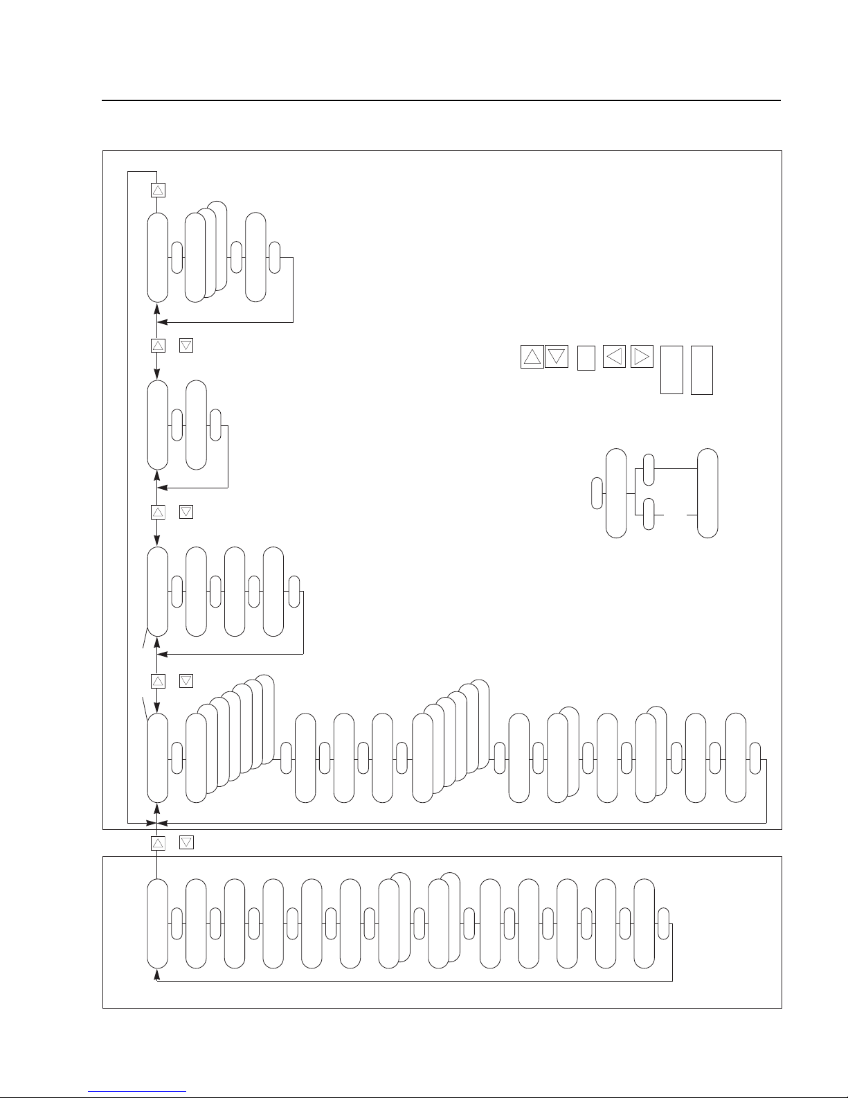
Converter Control MAG.DRIVE L2
57
GA 05.130/3.02 - 05/98
4.6.6 Total view of the menu
Programming menu
German
Vent
TMS ok
No Purge gas
No Cooling Water
Frequency
Set Converter
Enter
Motor Current
Option Relay
Bearing Temp.
Enter
Threshold
60 °C
Enter
Threshold
10.0 A
Enter
Threshold
300 Hz
Enter
Actual PZ12
Actual PVW24
Actual PVW13
Bearing Temp.
Actual Frequency
Analog Output
Motor Current
Enter
Scale factor
1.0 x
Enter
Freq. Setpoint
Analog Input 2
No Function
Enter
Start delay
0 s
Enter
Display
English
Enter
Bus address
0
Enter
Acoustic Alarm
Off
Enter
Selects the parameterization menu from the
operating display.
Switches forward to the next main menu.
Switches back to the last main menu.
Selects submenu.
Confirms to store changed parameters.
Increases a parameter value or switches
forward to the next option.
Reduces a parameter value or switches
back to the last option.
Starts the pump. Only possible from the
basic menu.
Stops the pump.
Return to the operating display from
parameterization menu.
START
STOP
ENTER
Stop
Data to Eeprom?
Stop=no Enter=yes
Enter
Ready
00.0 A 0000 Hz
Stop
Data are stored
in the EPROM
To exit the parameterization menu
Ready
0.0 A 0 Hz
Enter
Freq. Setpoint
480 Hz
Enter
Operation Hours
0.00 h
Enter
Motor Temp.
50 °C
Enter
Converter Temp.
40 °C
Enter
Bearing Temp.
50 °C
Enter
Actual PVW 13
10%
Enter
Actual PVW 24
10%
Enter
Actual PZ 12
5%
Enter
Power
400 W
Enter
Not Active
Actual Value TMS
63 °C
Enter
Not Active
Cooling Temp.
20 °C
Enter
Basic menu
Via X1
Purge ON
Set Pump
Enter
Normal Operation
95 %
Enter
Max. Accel. time
800 s
Enter
Pump Type
MAG 1600/2000 CT
Enter
Set TMS
Enter
TMS Setpoint
60 °C
Enter
Set Purge/Vent
Enter
Purge/Vent
Purge OFF
Enter
Option P/V
Option 1
Enter
ororor
Main menus
Software Version
103.04
Enter
or
Page 58

Converter Control MAG.DRIVE L
4.7. Temperature Management System
4.7.1 Temperature Management System for
the MAG.DRIVE L
Function description
The TMS is only in function, when a MAG1600/2000 CT
version is connected.The heater will be activated when
the mains is switched on. The TMS (TCU) controls the
heating and water cooling to maintain the pump at the
specified setpoint temperature.
Settings
Principally the factory presettings will be used. The settings are saved in the pump’s memory chip.Before changing any setpoint value request Leybold! The following
parameters are progammable via the key panel or the
serial interface when the pump stands still.
• Setpoint Temperature
• Warning Temperature
• Failure Temperature
For the settings refer to 4.5.5 Operating menu, Settings
TMS.
Heat up
The setpoint temperature will be reached within 30 to 60
minutes depending on cooling water temperature and
flow. If the flow is very high and the temperature low a
high temperature setpoint might not be reached. For
temperature sensitive applications observe the cooling
water specifications (refer to section 1.6 Technical Data).
Actual temperature
The actual TMS is displayed on the operating display
(refer to 4.5.1 Operating menu, Basic menu)
Signal TMS OK
If the actual TMS (TCU) temperature lies in the range
±5K from the setpoint temperature, the TMS OK signal
can be output via the option relay. The option relay must
be programmed for this function (refer to Section 2.8.3
Control plug X1, Relay outputs)
Warning message
If the actual temperature exceeds the warning temperature the converter displays the message:
warning
TCU
Failure message
If the actual temperature exceeds the failure temperature the converter displays the message:
failure
TCU
The pump is decelerated. After the pump has cooled
down, the failure can be ackno wledged and the pump restarted.
58
GA 05.130/3.02 - 05/98
Page 59
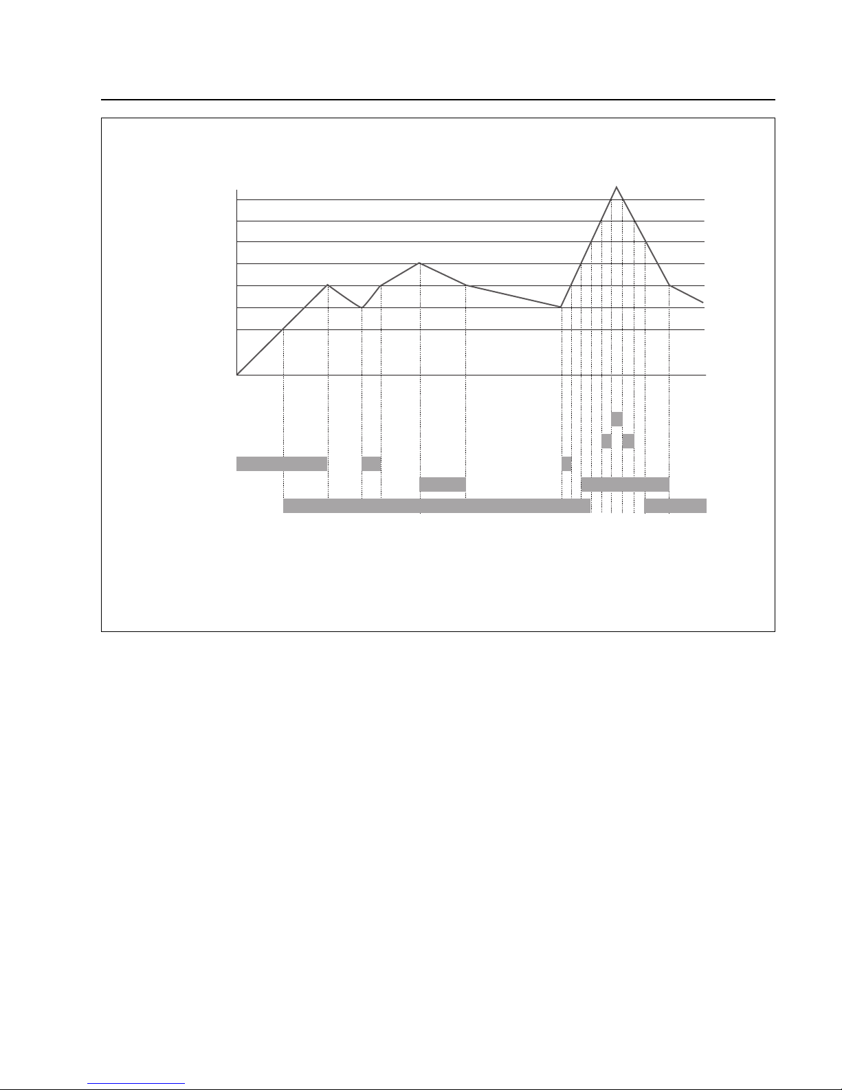
Converter Control MAG.DRIVE L
59
GA 05.130/3.02 - 05/98
Setpoint Temp. T
Failure
Warning
Heater ON
Cooling ON
Signal TMS OK
Failure
Warning
T + 5 K
T + 2 K
T - 5 K
T - 2 K
Fig. 46 Function diagram TMS for the MAG.DRIVE L
Page 60

Converter Control MAG.DRIVE L2
60
GA 05.130/3.02 - 05/98
4.7.2 Temperature Management System for
the MAG.DRIVE L2
Function description
The TMS is only in function, when a MAG1600/2000 CT
version is connected.The heater will be activated when
the mains is switched on.The TMS controls the heating
and water cooling to maintain the pump at the specified
setpoint temperature.
Settings
The temperature (TMS) setpoint can be programmed via
the front panel keys or the serial interface when the
pump stands still.
Principally the factory presetting will be used.The setting
is saved in the pump’s memor y chip. Before changing
any setpoint value request Leybold!
For the setting refer to 4.6.4 Operating menu, Settings
TMS.
Heat up
The setpoint temperature will be reached within 30 to 60
minutes depending on cooling water temperature and
flow. If the flow is very high and the temperature low a
high temperature setpoint might not be reached. For
temperature sensitive applications observe the cooling
water specifications (refer to section 1.6 Technical Data).
TMS status code
The TMS status code is displayed on the operation display, see Section 4.2.
Actual temperature
The actual temperature is displayed on the oper ating display (refer to 4.6.1 Operating menu, Basic menu)
Signal TMS OK
If the actual TMS temperature lies in the r ange ±5K from
the setpoint temperature, the TMS OK signal can be out put via the option relay. The option relay must be programmed for this function (refer to Section 2.8.3 Control
plug X1, Relay outputs)
Warning message (Temp > T
set
+5K)
If the actual temperature exceeds the warning temperature the converter displays the message:
Warning
TMS
Page 61
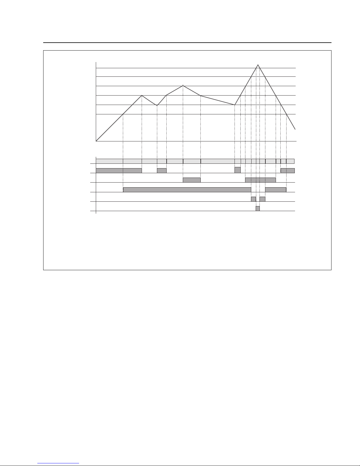
Converter Control MAG.DRIVE L2
61
GA 05.130/3.02 - 05/98
T - 5 K
T - 2 K
T + 2 K
T + 5 K
2)
2)
T + 15 K
1)
1 2
3
2 3
4
3 2 2 133
4 455
Sollwert TMS
TMS Code
Heizung EIN
Kühlung EIN
TMS OK
Warnung TMS
Störung TMS
1) The TMS status code is displayed on the operation display;see Section 4.2.
2) Heater or cooling active
Fig. 47 Function diagram TMS for the MAG.DRIVE L2
Setpoint temp.T
TMS Code
Heater ON
Cooling ON
TMS ok
Warning Temp.TMS
Failure TMS 5
Page 62
5 Maintenance
The MAG is maintenance-free. Wear only occurs at the
touch-down bearings when hard shocks have to be supported or when the pump frequently runs down without
venting.
Maintenance is also required after removing the bearing
cable during operation of the pump.
Under these conditions the rotor can not be controlled by
the magnet bearing and the pump will have a full run
down on the touch down bearing.
5.1 Removing the pump
from the system
MAG which hav e been used in semiconductor processes
are contaminated by semiconductor process gases.
Most of these gases form acids when exposed to moist
air which causes serious corrosion damage to the pump.
To prevent corrosion damage during storage and shipping, use the seal kit.
Failure to seal a contaminated MAG voids the warranty.
The seal kit contains the following
- dry car tr idge,
- plastic cap for forevacuum connection flange,
- plastic adhesive film and
- aluminum cover and screws for the high-vacuum
connection flange.
Proceed as follows to seal the turbomolecular pump
immediately after removing it from your process.
Purge the pump for two hours with the backing pump
running. This helps to remove a large quantity of the process gases from the pump.We recommend purging the
pump via the intake flange and the purge valve with
approx. 200 sccm.
Press the STOP button at the MAG.DRIVE and wait until
the pump has come to a standstill.
Afterwards turn the mains switch to the „0“ position.
The cables between the MAG and MAG.DRIVE may be
disconnected only after the MAG has come to a full stillstand and the mains is switched off.
Warning
When the pump has been pumping hazardous gases, ensure that proper safety precautions are taken before opening the intake or exhaust connections.
Use gloves or protective clothing to avoid
skin contact with toxic or highly corrosive
substances. Work under a fume hood if
available.
Disconnect the cables from the pump.
Disconnect the forevacuum line.
Disconnect the cooling water lines. Remaining cooling
water may flow out.Protect all par ts below.
Remove 10 of the 12 bolts which hold the intake flange.
The 2 remaining bolts must be directly opposite.
Support the pump with a lift-truck at the base plate and
remove the 2 remaining bolts.
Clean the intake and forevacuum connection flange as
necessary for good adhesion of tape.
Place the dry cartr idge into the forevacuum port. Don’t
use loose crystals.
Firmly seal all ports with plastic adhesive film.
Cover the forevacuum connection port with its plastic
cap.
Seal the high-vacuum connection flange with the cover
and the screws.
Pack the pump so that it may not be damaged during
transportation. Particularly protect the flanges, the cooling water connectors and the current feedthrough.
Only for MAG 1600
As the plastic adhesive film is too large for the high-v acuum connection flange slit it a little bit at the screw holes.
GA 05.130/3.02 - 05/98
Maintenance
62
Page 63
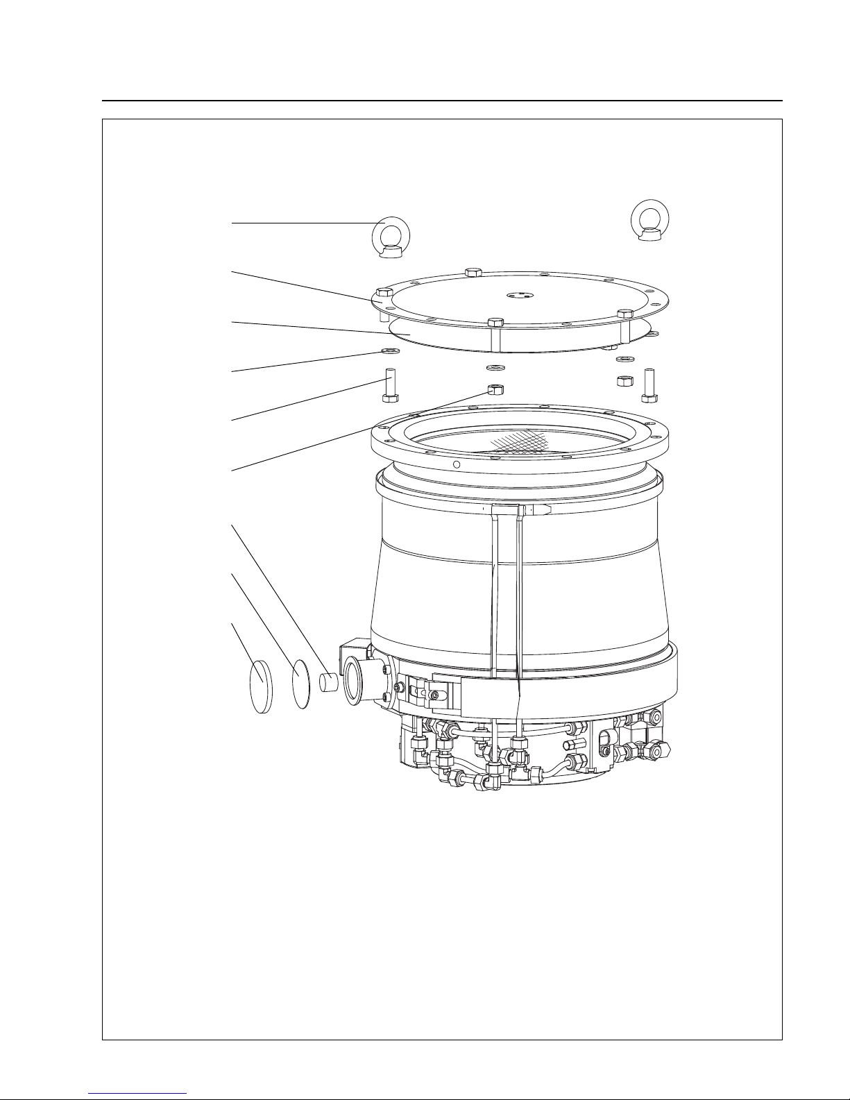
Maintenance
63
GA 05.130/3.02 - 05/98
Fig. 48 Sealing the MAG tightly
ring nut (2x)
aluminum cover
plastic adhesive film
washer (6x)
screw (6x)
nut (4x)
dry cartridge
plastic adhesive film
plastic cap
Page 64

Maintenance
64
GA 05.130/3.02 - 05/98
5.2 Service at Leybold’s
If you send a pump to Leybold indicate whether the
pump is free of substances damaging to health or
whether it is contaminated.If it is contaminated also indicate the nature of hazard.To do so, you must use a preprinted form which we shall send to you upon request.
A copy of this form is printed at the end of the Operating
Instructions: „Declaration of Contamination of Vacuum
Equipment and Components“.
Either fasten this form at the pump or simply enclose it to
the pump.
Don’t pack the form with the pump into the PE bag.
This declaration of contamination is necessary to comp-
ly with legal requirements and to protect our staff.
Leybold must return any pump without a declaration of
contamination to the sender’s address.
Page 65

6 Troubleshooting
In case of a malfunction, the MAG will be braked and the
first line of the display shows
FAILURE
Malfunction messages can be cancelled once the pump
has come to a stop and after the malfunction has been
rectified; do so with the STOP function (button or serial
interface).
Warning
The MAG shall be stopped completely and
the mains power cord detached before you
open the MAG.DRIVE. Since dangerous
voltages may nonetheless be encountered,
the housing must be opened only by a qualified electrician.
Troubleshooting
65
GA 05.130/3.02 - 05/98
Page 66
Troubleshooting for the MAG.DRIVE L
66
GA 05.130/3.02 - 05/98
Warning/Failure Message
on Display
Temp. Motor
Temperature sensor inside
the motor reads a higher
temperature than the limitation.
temp. pump
Temperature sensor inside
the pump reads a higher
temperature than the limitation.
temp. cool. water
Temperature sensor at cooling water block reads a higher temperature than the
limitation.
TCU
Temperature sensor at base
flange reads a higher temperature than the limitation.
temp. converter
Temperature sensor inside of
the converter reads a higher
temperature than the limitation (65 °C).
unbalanc. PVW13
unbalanc. PVW24
unbalanc. PZ12
Converter senses that rotor
displacement has exceeded
the limitation.
Corrective Action
Check BEARING connector and cable.
Measure resistance of KTY (temperature
sensor motor) at BEARING connector
(pump side) between X23/x - X23/w, default
2kΩ ± 1 %.
Service pump.
Set cooling water according to specifications. Check cooling lines for deposits. See
Section 2.6.
Check cable, Pt 100 wires and connector. In
particular measure resistance between
X23/v - X23/u and X23/v - X23/t, typical resistances are in the range of 110 Ω to 130 Ω
at 20 °C to 70 °C.
Set cooling water according to specifications. Check cooling lines for deposits. See
Section 2.6.
Check TMS cable, Pt 100 wires and connector.In par ticular measure resistance between X30/V - X30/S, typical resistances are
in the range of 110 Ω to 130 Ω at 20 °C to
70 °C.
Set cooling water according to specifications. Check cooling lines for deposits. See
Section 2.6.
Check TMS cable, Pt 100 wires and connector.In par ticular measure resistance between X30/F - X30/H and X30/F - X30/G,
typical resistances are in the range of 110 Ω
to 130 Ω at 20 °C to 70 °C.
If temperature sensor TMS (Pt 100) is
ok,unplug it.The water valve should open
instantly with a clicking noise and the red
LED inside the valve connector lights up.
Let the converter cool down and restart.
Check mounting position and clearences
inside the rack. See Section 2.8.Check
ambient temperature and watch for other
heat sources.
Acknowledge failure by by pressing stop and
try to restart pump.
Check unbalance PV13 / PW24 / PZ12 reading via display (basic menu) during accelleration. Check BEARING connector and
cable for bended pins.
Check the chamber pressure in the operation cycle. Remove transport seal; see Section 2. 4.
Replace pump or converter or whole
system.
Possible Cause
BEARING cable or connector damaged.
Drive failure.
No or too low cooling water.
BEARING cable or connector damaged. Pt
100 (temp.sensor bear ing) damaged.
No or too low cooling water.
Temperature sensor cooler (Pt 100) failure.
TMS cables damaged.
No or too low cooling water.
Temperature sensor TMS (Pt 100) failure or
TMS cable or connectors damaged.
Water valve malfunction.
Frequent run up and down.
No sufficient air circulation.
Mechanical shocks, perhaps due to tool
maintenance.
BEARING cable or connector damaged.
High active magnetic bearing current due to
shock venting or transport seal not removed.
Internal failure.
6.1 Troubleshooting for the MAG.DRIVE L
6.1.1 Warning and failure messages
Page 67
Troubleshooting for the MAG.DRIVE L
67
GA 05.130/3.02 - 05/98
Failure Message
on Display
MB-Code wrong
Converter senses that
magnetic bearing is not
active.
no motor current
max. accel.Time
The maximum acceleration
time has been exceeded.
max. power time
Rotational speed dropped
below normal operation
range for more than the max.
accel. time.
min. frequency
Rotational speed dropped
below the minimum frequency threshold.
Corrective Action
Replace converter.
Check cables and connectors, straighten
pins if required.
Replace pump.
Check pressures.
Set parameter max. Accel.time to default
1000 s. See Section 4.5.3/4.6.3 Settings
pump.
Check pressures.
Set parameter max. Accel.time to default
1000 s.
Set parameter Normal Operation to default
95 %.
See Section 4.5.3/4.6.3 Settings pump.
Check pressures.
Possible Cause
Internal fuse for power supply active magnetic bearing PC boards blown.
Overloaded active magnetic bearing.
BEARING cable connected while the con-
verter was powered.
DRIVE cable not connected or damaged.
Connectors damaged or pins have no
contact.
Motor coils damaged.
Backing pressure or inlet pressure too high
during start-up.
Parameter max.Accel. time is not set properly.
Backing or inlet pressure too high.
Process flows too high.
Parameters max.Accel. time or Normal
Operation not set properly.
Backing or inlet pressure too high.
Process flows too high.
6.1.2 Failure messages
Page 68
Troubleshooting for the MAG.DRIVE L
68
GA 05.130/3.02 - 05/98
Warning Message
on Display
PK communication
Converter does not communicate with the memory chip
inside of the pump.
max. power
max. frequency
Kin. Buffer
The converter works in
generator mode.
Corrective Action
Check BEARING cable and connectors.
Replace pump.
Check pressures.
Set parameter max. Accel.time to default
1000 s.
Set parameter Normal Operation to default
95 %.
See Section 4.5.3/4.6.3 Settings pump.
Motor current decreases to 0 Amp.The rotor
frequency decreases to the normal operati-
on range via gas friction.
Switch the mains power on. Locate and eli-
minate the cause of the mains failure.The
pump should handle numerous power failu-
res.
Possible Cause
BEARING cable not connected or damaged.
Memory chip inside magnetic bearing car-
tridge is damaged.
Backing or inlet pressure too high.
Process flows too high.
Parameters max.Accel. time or Normal
Operation not set properly.
Frequency exceeds the setpoint for more
than 2 Hz.
Mains power off.
6.1.3 Warning messages
Page 69
Troubleshooting for the MAG.DRIVE L
69
GA 05.130/3.02 - 05/98
Malfunction
Converter dead, nothing
happens after mains switched on.
Display malfunction, confusing failure messages.No
reaction when pressing keys.
Leaks of the vacuum chamber while the pump is stopped.
No purge gas flow
Pump does not accelerate to
more than 16 Hz
Base pressure not reached.
MAG does not heat up.
Display becomes blurred.
Corrective Action
Check if the green LED above the mains
switch lights up.Check mains cable and
connectors. Check power supply.
Replace converter.
Replace converter.
Open and close purge gas and venting valve
via control plug X1. LED on the valve must
light up and a clicking noise can be heard.
Foreline pressure drops while the valve is
closed.
Set purge flow according to specification.
Open and close purge gas and venting valve
via control plug X1. LED on the valve must
light up and a clicking noise can be heard.
Foreline pressure drops while the valve is
closed.
Compare pump type (label on the pump)
with parameter setting. Refer to Section
4.5.3/4.6.3 Settings pump.
Check pressures.
Replace converter or pump or whole
system.
Let the pump system run for 3 to 5 hours to
reach a base pressure below 10-5mbar.
Check TMS setpoint.Default 63 °C. Refer to
Section 4.5.5.
Replace fuse (F 4 A, 5x20 mm).
Measure resistance of heater, typical
approx. 70 Ω (connector pump side X30/A
and X30/B).
Measure resistance between pins X31/A1
and X31/A2 at TMS cable when pump is
connected.
It’s just the display. It becomes distinct at
moderate temperatures.
Possible Cause
No power supply.
Fuse F1 blown.
Internal failure.
Purge gas and venting valve open or malfunctioning.
No purge gas flow.
Valve malfunction.
Wrong setting in the programming menu:
Settings pump: pump type
No vacuum at all.
Internal converter or pump failure.
Degassing surfaces of rotor and stator. If the
pump was not stored in a dry environment
or was too long open to wet ambient air all
internal surfaces will be covered with a layer
of water.
Wrong setting TMS setpoint.
Fuse F3 at rear panel of converter blown or
damaged.
TMS heater jacket defective.
TMS cable or connectors damaged.
Converter temperature high or very low.
6.1.4 Malfunctions
Page 70
Troubleshooting for the MAG.DRIVE L2
70
GA 05.130/3.02 - 05/98
Warning Message
on Display
Motor Temp.
Temperature sensor inside
the motor reads a higher
temperature value than the
warning threshold (100 °C).
Message will not be activated as long as warning threshold = failure threshold.
Bearing Temp.
Temperature sensor inside
the pump reads a higher
temperature value than the
warning threshold (68 °C).
Cooling Temp.
Temperature sensor at cooling water block reads a higher temperature value than
the warning threshold (40
°C).
Converter Temp.
Temperature sensor inside of
the converter reads a higher
temperature value than the
warning threshold (69 °C).
Overspeed
The frequency exceeds the
frequency setpoint by more
than 10 Hz.
TMS
TMS temperature sensor
reads a temperature higher
than the TMS setpoint +5 °C.
Unbalanc. PVW13
Unbalanc. PVW24
Unbalanc. PZ12
A rotor displacement exceeding the warning threshold
occured.The code designates the affected axis.
Overload
The rotational speed dropped below normal operation
frequency.
Measures
Take the actual motor temperature reading
from the display; see Section 4.6.1.
Reduce gas load. If the warning persists
contact Leybold service.
Contact Leybold service.
Apply cooling water according to specifications. Check cooling water tubes for deposits.
See also Section 2.6.
Allow pump to cool down between the
cycles.
Apply cooling water according to specifications. Check cooling water tubes for deposits.
See also Section 2.6.
Allow converter to cool down between the
cycles.
Refer to Section 2.8 for the correct mounting
of the converter in a rack; max.ambient tem-
perature 45 °C.
Motor current decreases to 0 Amp.The rotor
frequency decreases to the setpoint via gas
friction.
Apply cooling water according to specificati-
ons. Check cooling water tubes for deposits.
See also Section 2.6.
Check the TMS setpoint (default 63 °C). For
the correct setting refer to Section 4.6.4.
If warning message persists contact Leybold
service.
Check the chamber pressure during operati-
on.
Contact Leybold service.
Reduce backing pressure.Additionally,
check process gas flow.
Set parameter „Normal Operation“ to default
95%. Refer also to Section 4.6.3.
Possible Cause
Motor temperature exceeds the warning
threshold e.g. due to a high gas load.
Drive failure or internal converter failure.
Cooling water flow too low or cooling water
temperature too high.
Frequent acceleration and deceleration of
the pump.
Cooling water flow too low or cooling water
temperature too high.
Frequent acceleration and deceleration of
the pump.
No sufficient air circulation.
Changing the frequency setpoint during operation to a lower value.
Cooling water flow too low or cooling water
temperature too high.
Wrong TMS temperature setpoint.
Mechanical shocks, perhaps due to tool
maintenance.
Shock venting.
Converter failure.
Backing pressure too high during operation.
Parameters „Normal Operation“ are not set
correctly.
6.2 Troubleshooting for the MAG.DRIVE L2
6.2.1 Warning messages
Page 71

Troubleshooting for the MAG.DRIVE L2
71
GA 05.130/3.02 - 05/98
Warning Message
on Display
Kinetic Buffer
The converter is in the generator mode.
Op.Without Purge
The warning indicates that a
C/CT type of pumpis operated while the purge gas
valve is closed.
Measures
Reconnect converter to the mains.
Switch on the converter.
Set purge gas function to Purge ON. (Key
panel or control connector X1).
Possible Cause
Mains interrupted or converter switched off
during operation of the pump.
Purge gas function disabled.
Page 72

Troubleshooting for the MAG.DRIVE L2
72
GA 05.130/3.02 - 05/98
Failure Message on
Display
Motor Temp.
Temperature sensor inside
the motor reads a higher
temperature value than the
failure threshold (100 °C).
Cooling Temp.
Temperature sensor at cooling water block reads a higher temperature value than
the failure threshold (50 °C).
Measures
Acknowledge failure message.
Take the actual motor temperature reading from the
display; see Section 4.6.1.
Reduce gas load. If the warning persists contact
Leybold service.
Step 1: Check pump (temperature sensor)
Check pump connector X23. In particular measure
resistance between pins X23/x and X23/w.The
resistance is typically 2kΩ ± 1 %. In case of abnormal values (> 3.4 kΩ) are measured contact Leybold service.
Step 2: Check BEARING cable
If step 1 was successful do the following:
Check BEARING cable for bent pins
Measure the resistance between pins X24/A9 and
X24/B9 with the cable connected to the pump.The
resistance is typically 2kΩ ± 1 %.
Replace the cable if it is damaged or in case the
measurement of the resistance shows abnormal
values (> 3.4 kΩ) now.
Contact Leybold service.
Apply cooling water according to specifications.
Check cooling water tubes for deposits. See also
Section 2.6.
Step 1: Check cooling water temperature sensor
Check pump connector X30. In particular measure
resistance between pins X30/S and X30/V. The
resistance is typically between 110 Ω and 130 Ω
(20 °C to 70 °C).
Step 2: Check TMS cable and connectors
If step 1 was successful do the following:
Check TMS cable for bent pins
Measure the resistance between pins X31/A4 and
X31/A5 with the TMS cable connected to the pump.
The resistance is typically between 110 Ω and 130
Ω (20 °C to 70 °C).
Replace TMS cable if it is damaged or in case the
measurement of the resistance shows abnormal
values now.
Contact Leybold service.
Possible Cause
Motor temperature exceeds the failure threshold e.g. due to a high gas
load.
Motor temperature sensor defective.
BEARING cable or connector damaged.
Converter failure.
Cooling water flow too low or cooling
water temperature too high.
Pt 100 (cooling water temperature
sensor) damaged.
TMS cable or connectors damaged.
Converter failure.
6.2.2 Failure messages
Page 73

Troubleshooting for the MAG.DRIVE L2
73
GA 05.130/3.02 - 05/98
Failure Message on
Display
Bearing Temp.
Temperature sensor inside
the pump reads a higher
temperature value than the
failure threshold (70 °C).
Converter Temp.
Temperature sensor inside of
the converter reads a higher
temperature value than the
failure threshold (74 °C).
TMS 1
The converter measures a
heating current of less than
300 mA when heater is on.
Measures
Apply cooling water according to specifications.
Check cooling water tubes for deposits. See also
Section 2.6.
Allow pump to cool down between the cycles.
Step 1: Check pump (temperature sensor)
Check pump connector X23. In particular measure
resistance between pins X23/v and X23/u as well
as between pins X23/v and X23/t.The resistance is
typically between 110 Ω and 130 Ω (20 °C to 70
°C). In case abnormal values are measured contact
Leybold service.
Step 2: Check BEARING cable
If step 1 was successful do the following:
Check BEARING cable for bent pins
Measure the resistance between pins X24/B7 and
X24/C7 as well as between pins X24/B7 and
X24/D7 with the cable connected to the pump.The
resistance is typically between 110 Ω and 130 Ω
(20 °C to 70 °C).
Replace the cable if it is damaged or in case the
measurement of the resistance shows abnormal
values now.
Contact Leybold service.
Allow converter to cool down between the cycles.
Refer to Section 2.8 for the correct mounting of the
converter in a rack; max.ambient temperature 45
°C.
Contact Leybold service.
Acknowledge TMS 1 failure message (possibly
several times).
Step 1: Check fuse
Replace fuse F3 (F4A, 5x20 mm) if blown.
Step 2: Check pump (heating element)
Check if the connector of the heating element is
connected.
Check pump connector X30. In particular measure
resistance between pins X30/A and X30/B.The
resistance is typically between 70 Ω and 75 Ω. In
case abnormal values are measured contact Leybold service.
Step 3: Check TMS cable
If step 2 was successful do the following:
Check TMS cable for bent pins
Measure resistance between pins X31/A1 and
X31/A2 with the cable connected to the pump.The
resistance is typically between 70 Ω and 75 Ω.
Replace the cable if it is damaged or in case the
measurement of the resistance shows abnormal
values now.
Contact Leybold service.
Possible Cause
Cooling water flow too low or cooling
water temperature too high.
Frequent acceleration and deceleration of the pump.
Pt 100 (temperature sensor bearing)
damaged.
BEARING cable or connectors damaged.
Converter failure.
Frequent acceleration and deceleration of the pump.
No sufficient air circulation.
Converter failure.
A TMS 2 ...5 failure occured and was
subsequently acknowledged.
Fuse F3 (rear panel) blown.
Heating element or internal pump
connection damaged.
TMS cable or connectors damaged.
Converter failure.
Page 74

Troubleshooting for the MAG.DRIVE L2
74
GA 05.130/3.02 - 05/98
Failure Message on
Display
TMS 2
The converter measures a
heating current of more than
4 A.
TMS 3
TMS temperature sensor
reads a temperature higher
than 99 °C.
TMS 4
TMS temperature sensor
reads a temperature lower
than 1 °C.
TMS 5
TMS temperature sensor
reads a temperature higher
than the TMS setpoint + 15
°C.
Measures
Check the line voltage (200-240 V +10% / -15%).
Repeat step 2of failure TMS 1. In case the measu-
red value is less than 60 Ω contact Leybold service.
Contact Leybold service.
Step 1: Check TMS sensor
Check pump connector X30. In particular measure
resistance between pins X30/F and X30/H as well
as between pins X30/F and X30/G.The resistance
is typically between 110 Ω and 130 Ω (20 °C to 70
°C).
Step 2: Additional TMS sensor test
If temperature sensor TMS (Pt 100) has the correct
resistance, unplug it while the pump is on power.
The water valve should open instantly with a
clicking noise and a red LED inside the cooling
water valve connector lighting up.This LED should
be on if the actual TMS temperature is higher than
the TMS setpoint + 2 °C.
Contact Leybold service if the sensor is defective.
Step 3: Check TMS cable
Check TMS cable connector X31. In particular
measure resistance between pins X31/A8 and
X31/C8 as well as between pins X31/A8 and
X31/B8.The resistance is typically between 110 Ω
and 130 Ω (20 °C to 70 °C).
Contact Leybold service if the TMS cable is damaged.
Contact Leybold service.
Repeat steps 1 and 2 of failure TMS 3. Contact
Leybold service if the sensor is defective.
Repeat step 3 of failure TMS 3. Contact Leybold
service if the cable is damaged.
Contact Leybold service.
Apply cooling water according to specifications.
Check cooling water tubes for deposits. See also
Section 2.6.
Repeat step 2 of failure TMS 3. Contact Leybold
service if cooling water valve is malfunctioning.
Check the TMS setpoint (default 63 °C). For the
correct settings refer to Section 4.6.4.
Possible Cause
Overvoltage.
Heating element defective.
Converter failure.
TMS sensor damaged.
TMS cable damaged.
Converter failure.
TMS sensor short-circuited.
TMS cable short-circuited.
Converter failure.
Cooling water flow too low or cooling
water temperature too high.
Cooling water valve malfunctioning.
Wrong TMS temperature setpoint.
Page 75
Troubleshooting for the MAG.DRIVE L2
75
GA 05.130/3.02 - 05/98
Failure Message on
Display
Overload PZ 12
Overload PV 13
Overload PW 24
An abnormal displacement
ot the rotor occured at frequencies between 0 and 5
Hz.The code designates the
affected axis.
MB
MB, Purge ON
MB, Purge OFF
An abnormal displacement
ot the rotor occured at frequencies between 130 Hz
and 480 Hz.
The additional message
gives information on the status of the purge gas valve
the moment the failure occured. It can be used to estimate the run down time of
the pump.
PK Communication
Converter does not communicate with the memory chip
inside of the pump.
MB-Code Wrong
Magnetic bearing controller
does not work.
Starting Time
The frequency has not reached 40 Hz 2 minutes after
the start command was
applied.
Accel.Time
The pump does not reach
the normal operation frequency after the set maximum acceleration time.
Overload Time
The rotational speed has
dropped below normal operation frequency and stays
there for longer than the
maximum „Accel.Time“.
Shutdown Freq.
Rotational speed dropped
below the shutdown frequency threshold (140 Hz).
Measures
Acknowledge failure message and restart
the pump.If failure message persists contact
Leybold service.
Remove transport seal; see Section 2.4.
Check BEARING connector and cable for
bent pins. Contact Leybold service if the
cable is damaged.
Acknowledge failure message and restart
the pump.If failure message persists contact
Leybold service.
Check the chamber pressure during the
operation. Refer to Section 3.3 for correct
venting of the pump.
Contact Leybold service.
Check BEARING connector and cable for
damages or bent pins. Contact Leybold service if the cable is damaged.
Contact Leybold service.
Contact Leybold service.
Reduce backing pressure.
Check if the rotor rotates freely. Contact Ley-
bold service if the rotor is damaged or
blocked.
Reduce backing pressure.
Set parameter „Accel.Time“ to default 1000
s; see Section 4.6.3.
Reduce backing pressure.Additionally check
process gas flow.
Set parameter „Normal Operation“ to
default 95 % and parameter „Accel.Time“ to
default 1000 s; see Section 4.6.3.
Reduce backing pressure.Additionally check
process gas flow.
Possible Cause
Mechanical shocks, possibly due to tool
maintenance whwn the rotor stands still.
Pump is still protected with transport seal on
power up.
BEARING cable or connector damaged.
Mechanical shocks, possibly due to tool
maintenance.
Shock venting.
Converter failure.
BEARING cable not connected or damaged.
Memory chip inside of magnetic bearing cartridge malfunctioning.
Converter failure.
Backing pressure too high during start-up.
Rotor blocked.
Backing pressure too high during start-up.
Parameter „Accel.Time“ is not set correctly.
Backing pressure too high during operation.
Parameters „Accel.Time“ or „Normal Operation“ are not set correctly.
Backing pressure too high during operation.
Page 76
Troubleshooting for the MAG.DRIVE L2
76
GA 05.130/3.02 - 05/98
Failure Message on
Display
Cooling Temp. SC
The cooling water temperature sensor reads a temperature lower than 1 °C.
Bearing Temp. SC
The magnetic bearing temperature sensor reads a temperature lower than 1 °C.
Motor Temp. SC
The motor temperature sensor reads a temperature
lower than 1 °C.
Connection pump
Frequency
Abnormal motor current or
frequency
Measures
Repeat step 1 of „failure Cooling Temp.“.
Contact Leybold service if the resistance of
the sensor is less than 100 Ω.
Repeat step 2 of „failure Cooling Temp.“.
Contact Leybold service if the resistance of
the sensor is less than 100 Ω.
Contact Leybold service.
Repeat step 1 of „failure Bearing Temp.“.
Contact Leybold service if the resistance of
the sensor is less than 100 Ω.
Repeat step 2 of „failure Bearing Temp.“.
Contact Leybold service if the resistance of
the sensor is less than 100 Ω.
Contact Leybold service.
Repeat step 1 of „failure Motor Temp.“.
Contact Leybold service if the resistance of
the sensor is less than 1.62 kΩ.
Repeat step 2 of „failure Motor Temp.“.
Contact Leybold service if the resistance of
the sensor is less than 1.62 kΩ.
Contact Leybold service.
Check if the BEARING cable is connected to
the pump and the converter.Acknowledge
failure message.
Contact Leybold service.
Check cables and connectors, straighten
pins if required.
Acknowledge failure message;see Section
4.4. If failure persists contact Leybold service.
Acknowledge failure message and restart
the pump.
Possible Cause
Temperature sensor Pt 100 shor t-circuited.
TMS cable short-circuited.
Converter failure.
Temperature sensor Pt 100 shor t-circuited.
BEARING cable short-circuited.
Converter failure.
Temperature sensor KTY shor t-circuited.
BEARING cable short-circuited.
Converter failure.
BEARING cable not connected.
Converter failure.
On START command: DRIVE cable not
connected or connectors damaged.
The rotor frequency exceeds 515 Hz.
A STOP commend followed by a START
command given while the warning „Overspeed“ is displayed.
Page 77
Troubleshooting for the MAG.DRIVE L2
77
GA 05.130/3.02 - 05/98
Malfunction
Converter dead, LED
„mains“ does not light up
after switching on.
Display malfunction, confusing messages. No reaction
when pressing keys.
Vacuum chamber pressure
rises above normal backing
pressure while the pump is
stopped.
No purge gas flow
Base pressure not reached.
MAG 1600/2000 CT does
not heat up.
Display blurred.
Measures
Check the line voltage.
Contact Leybold service.
Switch the converter off and on again. If the
converter still malfunctions contact Leybold
service.
Open and close purge gas and/or venting
valve via control plug X1.LED on the valve
must light up and a clicking noise can be
heard. Foreline pressure drops while the
valve is closed.
Set purge flow according to specification.
Open and close purge gas and venting valve
via control plug X1. LED on the valve must
light up and a clicking noise can be heard.
Foreline pressure drops while the valve is
closed.
Leave the pump system run for 3 to 5 hours
to reach a pressure below 10-5mbar.
See TMS failures.
Operate the converter according to the specifications.
Possible Cause
No power supply.
Fuse F1 blown or converter failure.
Converter failure.
Purge gas and venting valve open or malfunctioning.
Valve malfunctioning.
Degassing surfaces of rotor and stator. If the
pump was stored in a humid environment or
was exposed to humid ambient air all surfaces will be covered with condensation.
TMS failure.
Ambient temperature too high or too low.
6.2.3 Malfunctions
Page 78
Certifications
78
GA 05.130/3.02 - 05/98
EC declaration of manufacture
in accordance with Art. 4 paragraph 2 of EC directive 89/392/EEC changed
by 91/368EEC and 93/44/EEC, Appendix IIB
Document No.: MSR0196 / MAG.DRIVE L
Manufacturer: REFU elektronik GmbH
Product Identification: MAG.DRIVE L2
Catalog No.: 857 24
The product indicated solely for fitting in anorther machine.Commissioning is
prohibited until the conformity of the end product with EC directive
89/392/EEC has been established.
Standards applied: EN 60204-1 (DIN VDE 0113 part 1)
EN 61010-1 (DIN VDE 0411 part 1)
1.10. 1997
REFU elektronik GmbH
...................................................
H. Baumann
President
The savety notes given in the product documentation must be observed.
Page 79

Certifications
79
GA 05.130/3.02 - 05/98
EC declaration of conformity
Document No.: MSR0196 / MAG.DRIVE L
Manufacturer: REFU elektronik GmbH
Product Identification: MAG.DRIVE L2
Catalog No.: 857 24
Herewith, we declare that this product, as a result of ist design and type of
construction, and the version marketed by us, correspond to the basic health
and safety regulations specified in the EEC Directives.
This declaration is no longer valid if the product is modified without us being
in full agreement.
The product conforms to the EEC Low-Voltage Directive (73/23/EEC).
Standards applied: EN 61010-1 (DIN VDE 411 Teil 1) Edition 1994-03
Display the CE-mark: 1997
1.10. 1997
REFU elektronik GmbH
...................................................
H. Baumann
President
The savety notes given in the product documentation must be observed.
Page 80
Certifications
80
GA 05.130/3.02 - 05/98
Factory certificate
Document No.: MSR0196 / MAG.DRIVE L
Manufacturer: REFU elektronik GmbH
Product Identification: MAG.DRIVE L2
Catalog No.: 857 24
The named product, when put to ist intended use, satisfies the requirements
of Directive 89/336/EEC concerning electromagnetic compatibility.
The applicable measurements were made taking into account the following
standards:
EN 500 81-1
EN 500 82-2
EN 55011 (DIN VDE0875 Teil 1)
EN 61000-3-2
EN 61000-3-3
Note
Attention must be paid to the information provided on proper installation with
respect to elektromagnetic compatibility and to other pertinent notes in the
documentation supplied with the product, as well as to the relevant information concernning electrical connection.
1.10. 1997
REFU elektronik GmbH
...................................................
H. Baumann
President
The savety notes given in the product documentation must be observed.
Page 81
81
GA 05.130/3.02 - 05/98
Form TMP-1 … Turbopump Field Failure Report
Field Service IR No.: RMA No. (if returning to factory):
Service Center:
Customer:
Turbopump Model: Turbopump Pump Part Number:
Turbopump Serial Number:
Complaint:
Process:
OEM Equipment Name and Model:
Process Gas:
Was the turbopump replaced? ❐ Yes; ❐ No.
If yes, replacement pump P/N: replacement pump S/N:
Date Installed: Date Removed:
Date Received:
Date Examined: Examined by:
Received Condition:
Findings:
Cause of Failure:
Recommendations:
Remarks/Questions:
LEYBOLD AG
Fax to:Service LV
Fax#:(0049) 221 347 1945
LEYBOLD VACUUM
Page 82
GA 05.130/3.02 - 05/98
82
S A M P L E
Declaration of Contamination of Vacuum Equipment and Components
The repair and/or service of vacuum equipment and components will only be carried out if a correctly completed declaration has
been submitted. Non-completion will result in delay. The manufacturer could refuse to accept any equipment without a declaration.
This declaration can only be completed and signed by authorized and qualified staff.
1. Description of Vacuum Equipment and Components
- Equipment type/model: _________________________________
- Code No.: _________________________________
- Serial No.: _________________________________
- Invoice No.: _________________________________
- Delivery date:
__________________________
2. Reason for Return
____________________________________________
____________________________________________
____________________________________________
____________________________________________
____________________________________________
____________________________________________
3. Condition of the Vacuum Equipment and Components
- Has the equipment been used?
yes
❒ no ❒
- What type of pump oil/liquid was used? _________
- Is the equipment free from potentially
harmful substances?
yes ❒ (go to Section 5)
no ❒ (go to Section 4)
4. Process related Contamination of Vacuum
Equipment and Components:
- toxic yes ❒ no ❒
- corrosive yes ❒ no ❒
- explosive*) yes ❒ no ❒
- biological hazard*) yes ❒ no ❒
- radioactive*) yes ❒ no ❒
- other har mful substances yes ❒ no ❒
*) Vacuum equipment and components which have been contaminated by biological e xplosiv e or r adioactiv e substances , will
not accepted without written evidence of decontamination!
Please list all substances, gases and by-products which may have come into contact with the equipment:
Trade name
Product name Chemical name Dangerous Measures First aid in case of
Manufacturer (or Symbol) material class if spillage human contact
1.
2.
3.
4.
5.
Copies: Page 1 (white) to manufacturer or representative - Page 2 (yellow) attach to consignment packaging securety - Page 3 (blue) copy for file of sender
5. Legally Binding Declaration
I hereby declare that the information supplied on this form is complete and accurate.The despatch of the contaminated
vacuum equipment and components will be in accordance with the appropriate regulations covering Packaging, Transportation and Labelling of Dangerous Substances.
Name of organisation or company:_____________________________________________________________________
Address: _____________________________ Post code:______________________________________
Tel.: ______________________________________________________________________________
Fax: _____________________________ Telex: _________________________________________
Name: ______________________________________________________________________________
Job title: ______________________________________________________________________________
Date: _____________________________ Company stamp:
Legally binding signature:____________________________________________________________________________
Copyright © 1991 by MaschinenbauVerlag GmbH, Lyoner Straße 18, 6000 Frankfurt/M. 71 Order No.: 2121
Page 83

Notes
83
GA 05.130/3.02 - 05/98
Page 84

LEYBOLD VAKUUM GmbH
Bonner Strasse 498 (Bayenthal)
D-50968 Cologne
Tel.: + 49 (221) 347-0
Fax: + 49 (221) 347-1250
http://www.leyboldvac.de
e-mail:[email protected]
80000740 05.98 RSP Printed in Germany on chlorine-free bleached paper Technical alterations reserved
 Loading...