

Page 1
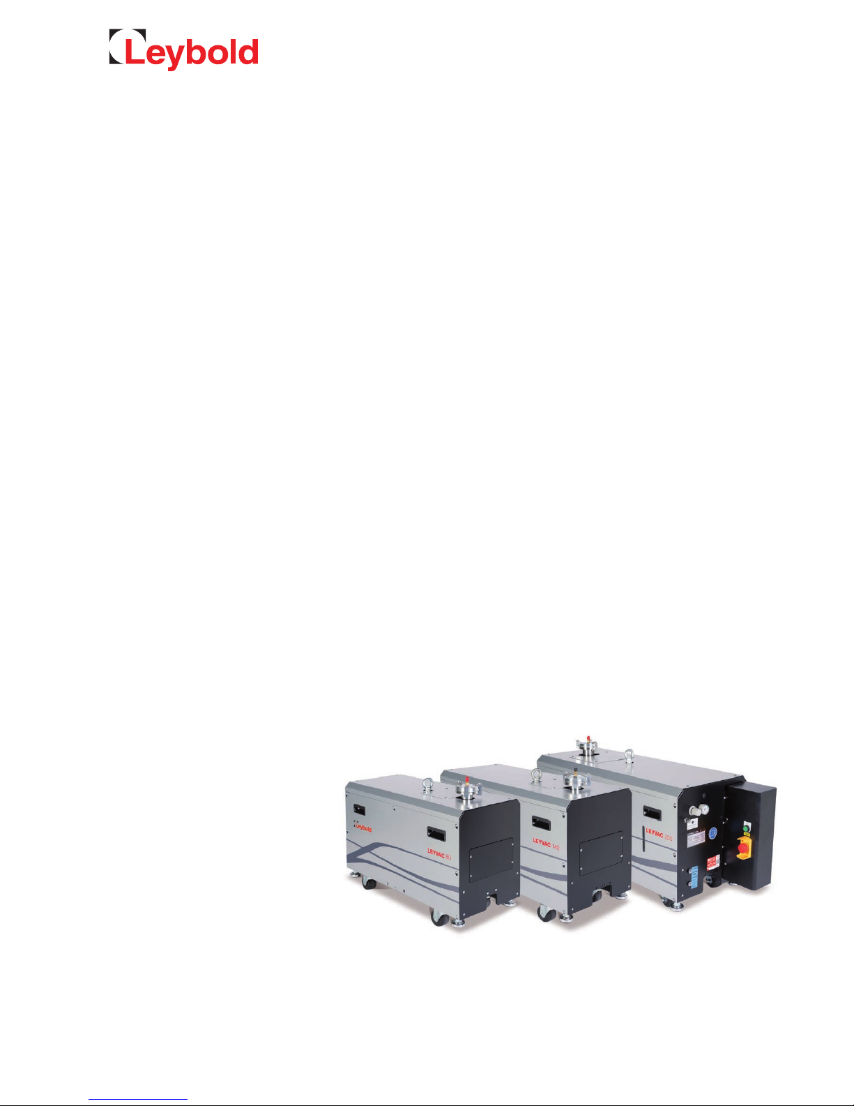
Part Numbers
115080V15 / 30 / 35 / 40
115140V15 / 30 / 35 / 40
115250V15 / 30 / 35 / 40
LEYVAC
LV 80, LV 140, LV 250
Dry Compressing Vacuum Pumps
Operating Instructions 300407956_002_C1
Page 2

Contents
2
300407956_002_C1 - 01/2017 - © Leybold
Page
0 Important Safety Information 5
Explanation of Warning Symbols 5
0.1 Mechanical Hazards 7
0.2 Electrical Hazards 8
0.3 Thermal Hazards 9
0.4 Hazards Caused by Materials and Substances 10
0.5 Ignition Risk 11
0.6 Noise Hazard 11
0.7 Dangers in Connection with safety-related
Measures and Precautions 12
0.8 Danger of Pump Damage 12
1 Description 14
1.1 Pump Module 14
1.2 Supplied Equipment 19
1.3 Technical Data 20
1.4 Ordering Information 22
2 Transport and Storage 23
3 Installation 25
3.1 Ambient Requirements and Placement 25
3.2 Conforming Use 26
3.2.1 Non-conforming Use 26
3.3 Connecting the Intake and Exhaust Lines 28
3.3.1 Intake Lines 28
3.3.2 Exhaust Lines 28
3.4 Connecting Cooling Water 30
3.4.1 Water Quality 30
3.5 Purge Gas Piping 31
3.6 Electrical Connection 32
3.6.1 Standard- and C-Type Pumps 33
3.6.2 CC-Type Pumps 35
3.6.3 Checking the Direction of Rotation 37
3.6.4 Connecting an external Frequency Converter 37
3.7 Mounting Accessories 40
3.7.1 Roots Pump Adapter 40
3.7.2 Non-return Valve and Silencers 42
3.7.4 Gas Ballast Kit (option) 44
Page 3

Contents
3
300407956_002_C1 - 01/2017 - © Leybold
Original installation and operating instructions.
4 Operation 46
4.1 Before Starting 46
4.1.1 Pumping of monoatomic Gas 47
4.2 Stop Pump 48
4.3 Venting 48
4.4 Removing from Service 49
5 Maintenance 51
5.1 Leybold Service 51
5.2 Maintenance Intervals 51
5.3 Exchanging the Lubricant 53
5.4 Exhaust Piping Connector 54
5.5 Pump Inlet Flange 54
5.6 Purge Gas Pressure and Flow Regulator 55
5.7 Cooling Water Piping 55
5.8 Coolant Level 55
6 Troubleshooting 56
6.1 Pump Malfunctions 56
6.1.1 Malfunctions with CC-type Pumps 56
6.2 Malfunctions with Frequency Converter Operations (option) 56
7 Waste Disposal 59
EC Declaration of Conformity 60
Declaration of Contamination 61
Page
Page 4
Safety Information
4
300407956_002_C1 - 01/2017 - © Leybold
Obligation to Provide Information
Before installing and commissioning the pump, carefully read these
Operating Instructions and follow the information so as to ensure optimum
and safe working right from the start.
The Leybold LEYVAC has been designed for safe and efficient operation
when used properly and in accordance with these Operating Instructions. It is
the responsibility of the user to carefully read and strictly observe all safety
precautions described in this section and throughout the Operating
Instructions. The pump must only be operated in the proper condi-
tion and under the conditions described in the Operating
Instructions. It must be operated and maintaine d by trained personnel
only. Consult local, state, and national agencies regarding specific requirements and regulations. Address any further safety, operation and/or maintenance questions to our nearest office.
DANGER indicates an imminently hazardous situation which, if not avoided, will result in death or serious injury.
WARNING indicates a potentially hazardous situation which, if not
avoided, could result in death or serious injury.
CAUTION indicates a potentially hazardous situation which, if not avoided,
could result in minor or moderate injury.
NOTICE is used to notify users of installation, operation, programming or
maintenance information that is important, but not hazard related.
We reserve the right to alter the design or any data given in these Operating
Instructions. The illustrations are not binding.
Retain the Operating Instructions for further use.
NOTE
DANGER
WARNING
CAUTION
NOTICE
Page 5
Safety Information
5
300407956_002_C1 - 01/2017 - © Leybold
0 Important Safety Information
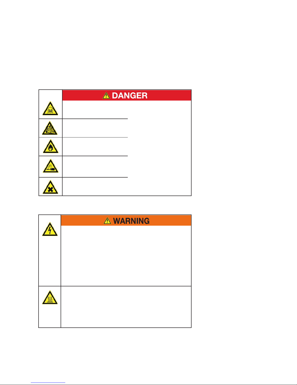
Explanation of Warning Symbols
Toxic gases
Danger of explosion
Fire danger
Reactive or corrosive
media
Contaminated parts
The pump must be leaktight.
When the pump has been used to
pump hazardous gases before,
introduce appropriate safety precautions before opening it. Before
opening the pump, purge it for a
longer period of time with an inert
gas. If necessary, wear gloves,
breathing protection or protection
clothing.
Hazardous Voltage
Disconnect power before opening.
Contact causes electrical shock.
High Leakage Current
Earth connection essential before connecting supply.
Electrical Hazards
Danger of residual voltage for up to 5 min after disconnecting power
supply. Connect and disconnect the mains plug only in deenergized
condition.
Hot Surface
Do not touch.
Allow this area to cool before servicing.
Burn hazard
Hot Surface inside. Do not touch, wear protective equipment.
Page 6
Safety Information
6
300407956_002_C1 - 01/2017 - © Leybold
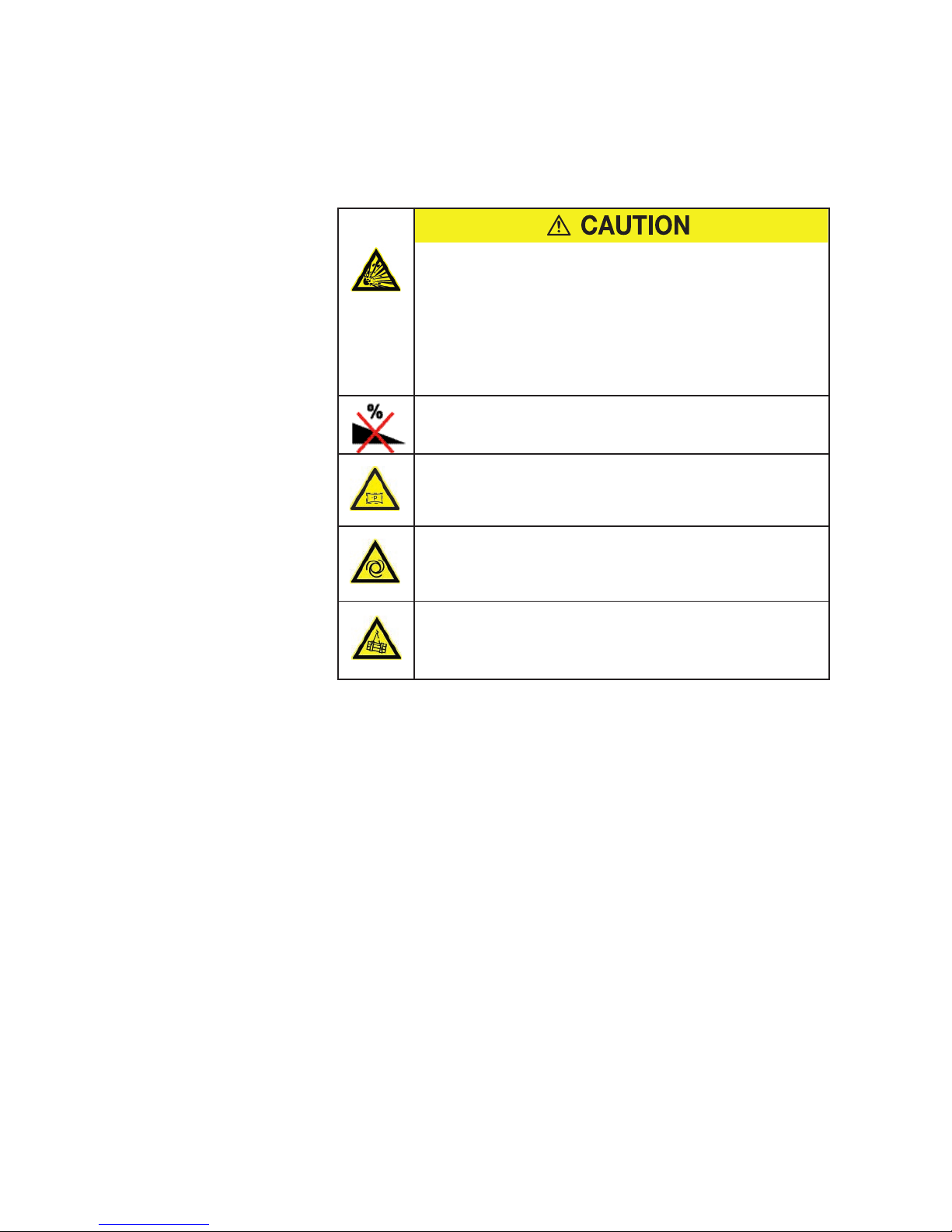
Purge gas
Check compatibility with applications
Overpressure in the discharge line
Components can be thrown in all directions.
The pressure in the discharge line must not exceed atmospheric
pressure by 300 mbar max.
The discharge line must not be blocked or restricted.
Pumps with wheels
must only be placed and moved on levelled horizontal surfaces!
Vacuum
Avoid exposing any part of the human body to the vacuum.
Machinery starts automatically
Connect the pump so that it not will restart automatically after a mains
power failure, once the power returns.
Overhead load
Transport the pump only secured with a forklift. Only qualified personnel
are allowed to unload and lift the pump. When elevating the pump, no
personnel should be under the object.
Page 7
Safety Information
7
300407956_002_C1 - 01/2017 - © Leybold
0.1 Mechanical Hazards
1 In order to avoid the destruction of systems and injury to operating
personnel we urgently recommend to observe the information and
installation information provided in these Operating Instructions.
2 Avoid exposing any part of the human body to the vacuum.
3 Do not operate the pump with an opened intake port. There exists the
risk of suffering injury.
4 The pump is intended for generating a vacuum only. If an overpres-
sure can occur in the pump and the system then they must be protected against such an overpressure by an overpressure safety valve,
for example.
5 The maximum permissible discharge pressure for the LEYVAC is
1.3 bar abs.
We recommend to operate the pump with a silencer or a connected
discharge line. The pressure in the discharge line must not exceed
atmospheric pressure by 300 mbar max.
Make sure that the gas flow at the discharge is not blocked or restricted in any way, even when the pumped out gases need to be collected
or contained.
No shutoff devices are required in the discharge line for pump operation. If shutoff devices are installed, open them before starting the
pump.
In the case of processes involving much condensate, we recommend
the installation of a condensate separator in the discharge line.
6 Protect the purge gas supply so that in the event of a malfunction or
power interruption no overpressure can occur within the pump system.
7 We recommend to design the discharge line in consideration of a pos-
sible overpressure of 5 bar. In the event of a malfunction, such a pressure can occur briefly.
8 For transporting the pump use only suitable transport means.
When selecting the lifting and transport means take note of the total
weight before transporting the pump.
Only the qualified personnel are allowed to unload and lift the pump.
When elevating the pump, no personnel should be under the object.
As standard the pump has been equipped with a single crane eye.
When transporting the pump with a forklift or similar, ensure that the
pump has been secured on the forks or on a suitable pallet.
Alternatively use two nylon slings as hoisting devices.
Be careful not to overturn the pump when pushing or pulling the pump
sideways.
WARNING
Page 8
Safety Information
8
300407956_002_C1 - 01/2017 - © Leybold
9 Select the location where the pump is installed so that all controls can
be easily accessed. Place the pump only on a floor which is level. It
can topple when it is tilted by more than 10° with respect to the vertical axis.
For pumps on castors only
Because of the fitted castors, the pump must only be placed on a level
floor capable of supporting the pump’s weight, as otherwise there
exists the risk of the pump rolling away. Moreover, the pump may only
be moved on a level floor! Moving the pump along sloping paths or
ramps is prohibited! The pump must only be transported with a forklift
or a crane! At the installation location, screw down the adjustable feet.
10 Before beginning with any maintenance and servicing work always
ensure that no gas can flow backwards through the pump since
then the rotors might turn against the normal direction of rotation. For
this reason vent the vacuum chamber to the discharge pressure level
or ensure through suitable valves that the vacuum chamber and the
lines are reliably separated from the pump. When connecting several
pump systems, pressure differences between inlet and discharge can
give rise to uncontrolled turning of the pump’s shafts.
11 During operation, the cooling water circuit must not be shut off. A
cooling water discharge which has been blocked can cause the formation of gas bubbles and result in excessively high pressures.
12 Lay electric feed and cooling water lines so that there is no risk of trip-
ping over these.
13 When changing the oil remove any escaped oil as otherwise there is
the risk of slipping.
14 Before doing installation work on the pump system make sure that no
vacuum is present in the pump and that all media connections have
been depressurised.
15 Before disassembling any cooling water lines, leave the pump to cool
down, shut off the feed line.
0.2 Electrical Hazards
1 The electrical connection must only be provided by a trained person.
Observe the national regulations in the country of use like EN 50110-1
for Europe, for example.
2 Potentially lethal voltages are present at the mains connections. Before
beginning with any maintenance or service work on the pump, disconnect the pump from all power supplies (lockout/tagout).
3 Install a device for a safe disconnection from the power supply.
4 High electric voltages! When touching parts at high electric voltages,
there is the risk of suffering severe injuries by an electric shock! Covers
marked with this symbol must only be opened by trained electricians
after having reliably deenergised (lockout/tagout) the equipment.
5 Always operate the pump with a properly connected protective earth
conductor and make sure that the motor casing is closed.
DANGER
Page 9
Safety Information
9
300407956_002_C1 - 01/2017 - © Leybold
6 The pump must only be operated at the frequency specified for the
motor.
7 After having connected the motor and each time after having made
changes to the wiring, check the motor’s direction of rotation.
A wrong direction of rotation can cause a pressure buildup on the
intake side. Moreover, the pump may suffer severe damage.
8 Install a suitable motor protection for the electric motor before starting
up for the first time. Note the information in these Operating
Instructions and on the nameplate.
9 Before starting, check to ensure that the junction box is undamaged,
run a visual inspection on on the seals.
10 Install add-on parts (pressure switches, for example) without any
mechanical tensions and protect these against being damaged by
impacts, for example.
11 Lay the connecting lines so that these cannot be damaged. Protect
the lines against humidity and contact with water. Avoid thermally
stressing the lines by unfavourable laying. Comply with the required
standards when designing and laying the electrical connections.
12 Provide strain relief for the connecting lines so that the plugs and the
line connectors are not subjected to excessively high mechanical
stresses.
13 Lay electric feed lines so that there is no risk of tripping over these.
14 The pump must be integrated in the system control arrangement so
that it can not run-up automatically after it has been shut down due to
overtemperature. This applies equally to emergency shut-down
arrange ments. After having determined the fault cause, the pump
should be switched on manually again.
0.3 Thermal Hazards
1 Under certain ambient conditions parts of the the pump may attain
temperatures over 80 °C. There then exists the risk of suffering burns.
Note the danger symbols on the pump and in the case of a hot pump
wear the required protection equipment. All work on a pump which is
“still warm from operation” should be done only whilst wearing protective gloves.
2 Handle the pump only while vented and after having let it cool down.
3 Before disassembling any cooling water lines, leave the pump to cool
down, shut off the feed line.
4 When uninstalling the cooling water lines, take note of splashing water.
Heated water can cause burns.
5 Never remove the oil-fill or oil-drain plugs while the pump is running.
There exists the risk of suffering burns. Always wear protective gloves
and protective goggles also for protection against the oil.
CAUTION
Page 10
Safety Information
10
300407956_002_C1 - 01/2017 - © Leybold
6 Operating the pump with less than the specified amount of cooling
water will result in excessively high surface temperatures. Moreover,
there exists the risk of suffering burns.
0.4 Hazards Caused by Materials and Substances
1 The vacuum line must be leaktight. Hazardous process gases may
escape or the pumped gases can react with air or atmospheric humidity. After installation of the pump and after servicing work on the vacuum system, a leak search will always be necessary.
When pumping toxic, corrosive and reactive gases we recommend a
leak search on a regular basis. Leaks in the pump cannot be ruled out
under all circumstances. When pumping hazardous gases, the operator must ensure that that leaks at the pump will not be a hazard.
2 Before commissioning the pump, make sure that the media which are
to be pumped are compatible with each other so as to avoid hazardous situations.
All relevant safety standards and regulations must be observed.
3 If required additional monitoring of the purge gas quantities is neces-
sary from the side of the operator when a well-defined and ensured
dilution is necessary from the side of the process.
The type of protection depends on the specific process and needs to
be assessed by of the customer.
4 The cooling water from the return is not of drinking water quality and
should not be used for this purpose.
After having operated the pump, the cooling water lines may suffer
from microbiological contamination. Take appropriate safety precautions.
5 Before operating the pump with a gas ballast or a purge gas check the
compatibility of the gas with the pumped media so as to avoid dangerous conditions during operation.
6 Secure the purge gas supply so that in the event of a malfunction no
overpressure can occur in the system.
7 When the pump has been used to pump hazardous gases before,
introduce appropriate safety precautions before opening the intake or
the discharge connections. Before opening the pump, purge it for a
longer period of time with an inert gas. If necessary, wear gloves,
breathing protection or protection clothing and work under a fume
hood. Firmly seal off the pump. When shipping the decontaminated
pump for servicing please also indicate the type of hazard. For this see
Section 5.1 Service at Leybold.
8 Leybold is not in a position to perform servicing (repairs) and waste
disposal of radioactively contaminated pumps. Both needs to be
ensured from the side of the user.
DANGER
Page 11
Safety Information
11
300407956_002_C1 - 01/2017 - © Leybold
9 When disposing of the pump, used lubricants and used oil filters
observe the applicable environment regulations.
10 When pumping hazardous gases you must assume the presence of
hazardous residues in the pump.
11 If the pump has been contaminated by the process or through envi-
ronmental influences, it must be decontaminated professionally.
Contaminated parts can be detrimental to health and the environment.
Before beginning with any repair and maintenance work inform yourself
about any possible contamination. When handling contaminated parts
observe the pertinent regulations and comply with the necessary protection measures.
When shipping contaminated pumps which require approval by the
authorities, note the applicable regulations regarding packaging and
shipping.
12 Some pumps use perfluoropolyether (PFPE) as lubricant.
When handling PFPE you should observe the following:
During thermal decomposition at temperatures over 290 °C toxic and
corrosive gases are released. When handling PFPE keep it way from
open fires. Do not smoke with PFPE on your fingers.
Touch the inner sections of the pumps only while wearing clean gloves,
and use clean tools;
do the necessary work in clean and dry rooms;
after having removed the pump from its packaging, start it up as
quickly as possible;
as cleaning agents solvents based on hydrofluorether compounds may
be used.
13 Fluoropolymers are used as sealants (FKM) and as lubricants (PFPE) in
the pumps. In case the pump suffers a severe mechanical failure, or is
misused, or was exposed in a fire, the possibility of hazardous substances being released owing to their thermal decomposition cannot
be excluded. Do not touch or inhale these thermal breakdown products of fluorinated materials.
0.5 Ignition Risk
The standard version of the pump must not be used to pump potentially
flammable atmospheres and is not suited for operation in explosion hazard
areas. Contact us before planning to use the pump under such circumstances.
0.6 Noise Hazard
The noise level of the pump during ultimate pressure operation with silencer or connected discharge line corresponds to the values stated in the
Technical Data. In other operating modes and with other equipment, higher
values must be expected. Make sure that suitable protection measures are
taken to protect your hearing.
We recommend to wear hearing protectors (earmuffs), if local noise levels
exceed mandatory limits.
DANGER
CAUTION
Page 12
Safety Information
12
300407956_002_C1 - 01/2017 - © Leybold
0.7 Dangers in Connection with safety-related
Measures and Precautions
Take note of the warning information on the casing surface. If this warning
information was removed, covered or obstructed, then provide corresponding additional warning information.
0.8 Danger of Pump Damage
1 Select an installation site for the pump so that all controls are easily
accessible.
2 The pumps are supplied filled with PFPE (LVO 410) or synthetic oil
(LVO 210). For this reason they should, while being transported or
shipped, not be subjected to tilting by more than 10° with respect to
the horizontal axis. Store the pumps only horizontally standing on their
feet.
3 When pumping dust containing media, install a dust filter in the pro-
cess gas flow upstream with respect to the pump.
4 When connecting the pump, provide a suitable valve on the intake side
for the purpose of shutting off the intake line so as to prevent the
pump from turning backwards in the event of a power failure.
Otherwise the pump may suffer damage or oil may contaminate the
pump chamber.
5 Lines and other vacuum connections should be clean and free of oil.
Special attention must be paid here when oil-sealed pumps have been
used on the vacuum side. Check the conditions before initial commissioning. In the case of deviations, the pump can suffer contamination
with oil residues.
6 The pressure within a pump which has been switched off will increase
to ambient pressure within a few seconds. In such a case the pump is
vented through the discharge. We recommend to fit a nonreturn dis-
charge valve.
7 The discharge line should be laid so that it slopes down and away
from the pump so as to prevent condensed vapours from backstreaming into the pump.
8 In the case of wet processes we recommend the installation of liquid
separators, upstream and downstream of the pump so as to avoid
the influx of liquid into the pump.
CAUTION
NOTICE
Page 13

Safety Information
13
300407956_002_C1 - 01/2017 - © Leybold
9 During installation work on the intake and discharge lines do not sub-
ject flanges to any stresses. Check the rubber elements of the pump’s
feet as to any deformation.
10 Before pumping condensable vapours the pump should be at oper-
ating temperature. If a gas ballast is present, then it should be opened.
The pump will attain its operating temperature approximately 120 minutes after having started the pump. During this warm-up phase, the
pump should be left separated from the process by a valve in the
intake line, for example.
11 If condensable vapours have been pumped, the pump should before
switching off be purged with an inert gas or air (depending on the specific application). This process should also be run before cleaning the
pump chamber.
12 For shutting down the pump let the pump operate idle for at least 30
minutes. Disconnect the pump from the mains power. Place desiccant
into the intake flange and into the discharge flange and blank off the
flanges with a piece of foil.
When storing the pump for a longer period of time, drain out the oil
first. Package the pump airtight in polyethylene foil.
13 Improper maintenance or repair work can have an influence on the
service life and the performance of the pump and will void any warranty claims.
14 Maximum cooling water pressure: 7 bar. When exceeded, there is
the risk of leaks.
Pressures given in bar or mbar are absolute values. If exceptionally a gauge
pressure is meant, a “g” is added (bar(g)).
Page 14
Description
14
300407956_002_C1 - 01/2017 - © Leybold
1 Description
1.1 Pump Module
Members of the LEYVAC vacuum pump family are of the dry compressing
single stage screw vacuum pump type. All LV models are positive displacement rotary pumps. During operating, the pump rotors are not in contact to
each other; therefore, there is no need of grease for lubricating or for sealing
the vacuum chamber. Thus, concerns in respect to oil dust backflows are not
applicable.
The pumps are water cooled and they are lubricated with PFPE (LVO 410) or
synthetic oil (LVO 210). Their purge gas system is equipped with a
24V-operated magnetic valve for both rotor purge and shaft seal purge, with
an additional manually operated valve fitted to the rotor purge line. There are
three different model types to be distinguished: The uncovered LEYVACs, the
C-type pumps with a cover installed, and the CC-type, equipped with covers
and an additional controller box.
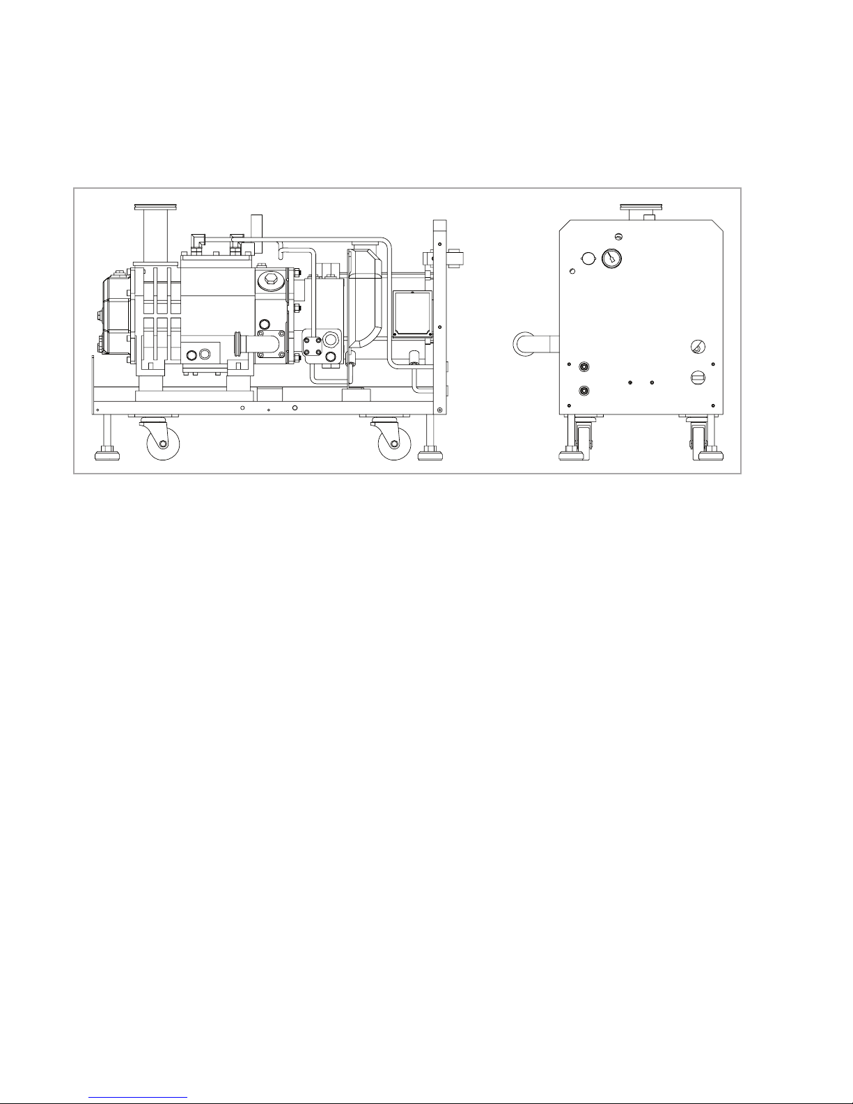
Fig. 1.1 LEYVAC LV 80; LEYVAC LV 140 and LV 250 similar
Page 15
Description
15
300407956_002_C1 - 01/2017 - © Leybold
2524
23
22
21
1918171615
14
13
12
11
10
123456789
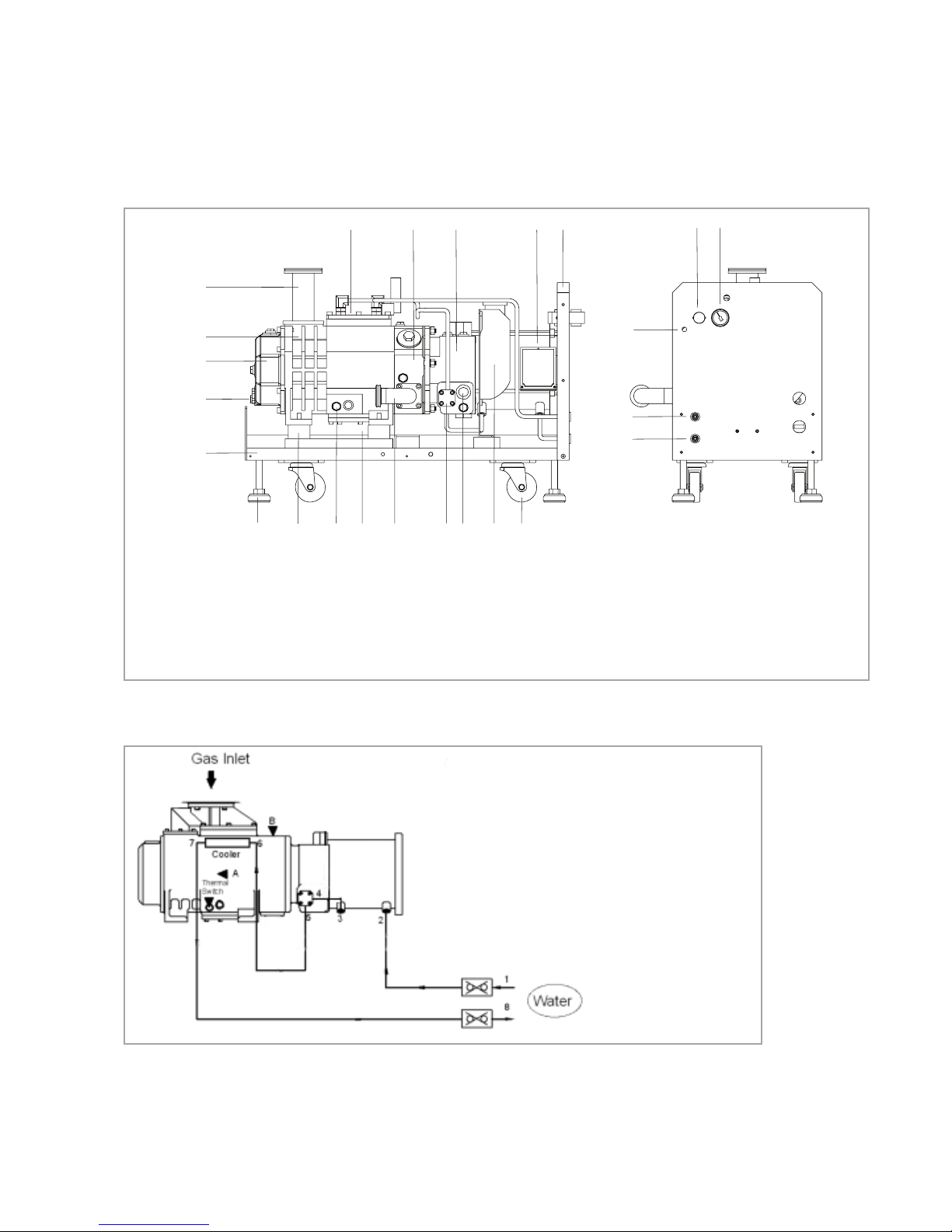
Fig. 1.2 LEYVAC LV 80 Pump Configuration; LEYVAC LV 140 and LV 250 similar
1. Castor
2. Expansion Vessel
3. Oil Level Indicator
4. Gear Box Cooler
5. Pump Outlet (Side)
6. Cooler
7. Casing Temperature Sensor
8. Shock-absorping Pad
9. Height-adjustment Foot
10. Pump Frame
11. Oil Level Indicator
12. Oil Box
13. Casing
14. Pump Inlet
15. Main Cooler
16. High Pressure Side Plate
Fig. 1.3 Cooling Water System
17. Gear Box
18. Motor
19. Front Panel
21. Cooling Water Inlet
22. Cooling Water Outlet
23. N2 Gas Inlet
24. N2 Pressure Regulator
25. N2 Pressure Gauge
1. Cooling Water Inlet
2. Cooling Water Inlet of Motor
3. Cooling Water Outlet of Motor
4. Cooling Water Inlet of Gear Box Cooler
5. Cooling Water Outlet of Gear Box Cooler
6. Cooling Water Inlet of Main Cooler
7. Cooling Water Outlet of Main Cooler
8. Cooling Water Outlet
Page 16
Description
16
300407956_002_C1 - 01/2017 - © Leybold
Cooling Water System
Fig. 1.3 shows the flow path entering at water inlet 1, cooling down the
motor (2 -> 3), the gear box (4 -> 5), the casing and the high pressure side
plate. Then it enters the main cooler (6 -> 7). After passing the main cooler at
7 the cooling water exits at outlet 8. Casing and high pressure side plate are
both cooled down by the coolant in the water jacket (indirect cooling).
There is another line between main cooler and expansion vessel, to resupply
the coolant. The expansion vessel has another pipe to balance its pressure.
There are thermal switches on motor and casing to protect the pump.
Connect the thermal switches of motor and casing to the protection circuit
of your equipment, or it might cause pump damage. With the LEYVAC CC
versions both temperature switches are connected to the CC controller. If
the CC pump is not sufficiently cooled, the pump will be switch off automatically to protect it from damage.
NOTICE
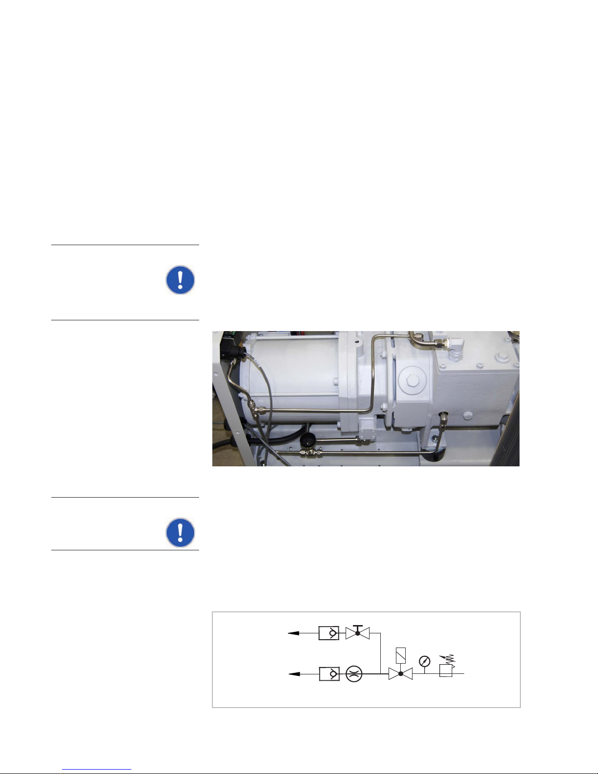
Purge Gas System
Operate the pump with purge gas at all times.
The pressurized purge gas comes into the pump via the inlet. Adjust the regulation pressure (by pressure regulator) to the specified value, and supply the
correct amount of purge gas to the pump. The pressure is shown at the
pressure gauge. The purge gas piping can be divided into two sets of pipe
lines.
LEYVAC LV 80 / 140
Purge Gas
Rotor Purge
Shaft Seal Purge
24 V DC
Fig. 1.4b Purge Gas System (schematic)
LEYVAC LV 80 / 140 / 250
NOTICE
Fig. 1.4a Purge Gas System
Rotor Purge (A) -->
24 VDC Valve
Shaft Seal Purge (B) -->
Page 17
Description
17
300407956_002_C1 - 01/2017 - © Leybold
Front Panel
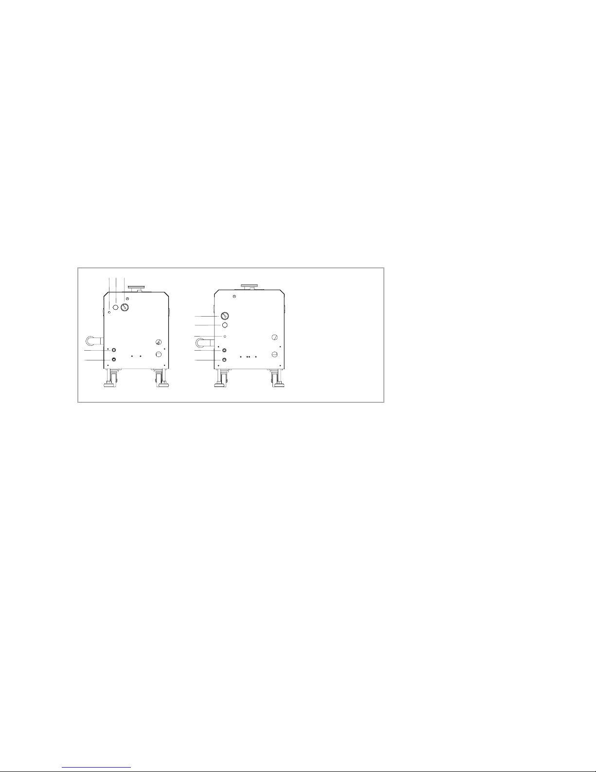
The connectors for cooling water (outlet over inlet) are RC3/8"; the connector
for the purge gas inlet is Swagelok 1/4". The maximum pressure for the
purge gas regulator is 2 bar (0.2 MPa), and the pressure is indicated at the
pressure gauge. Refer to the Technical Data Section for adjusting processdependent purge gas pressures.
CC-type pumps are additionally equipped with an EMO at the controller box
to enable the user to turn off the pump in case of an emergency.
Fig. 1.5 Front Panel Layouts
1
2
3
4
5
LEYVAC LV 80 CLEYVAC LV 140 C
123
4
5
1. Pressure Gauge
2. Pressure Regulator
3. Purge Gas Inlet
4. Cooling Water Outlet
5. Cooling Water Inlet
LEYVAC LV 80 C / 250 C
LEYVAC LV 140 C
Gas line (rotor purge): The main purpose is to decrease the partial pressure of the process gas in the pump, to reduce corrosion due to process
gas, and to retard the accumulation of reaction byproducts. The amount of
purge gas can be adjusted by the flow regulator, and the non-return valve
can prevent the process gases from getting into the purge gas pipe line.
Gas line (shaft seal purge): The main purpose is to prevent process gas
from entering the gear box through the high pressure side plate. The purge
gas will come into the rotating shaft in the high pressure side plate through
the non-return valve.
Page 18
Description
18
300407956_002_C1 - 01/2017 - © Leybold
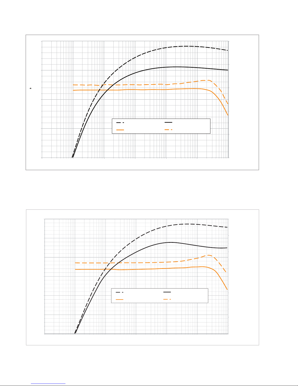
Fig. 1.6 Pumping Speed Curves for LEYVAC LV 80
0.0
1.0
2.0
3.0
4.0
5.0
0
25
50
75
100
0.001 0.01 0.1 1 10 100
[mbar]
60 Hz Pump Speed Air 50 Hz Pump Speed Air
50 Hz Power Air 60 Hz Power Air
[m
/h]
Power Consumption [kW]
Pumping Speed
Inlet Pressure
LEYVAC LV 80
Fig. 1.7 Pumping Speed Curves for LEYVAC LV 140
0.0
1.0
2.0
3.0
4.0
5.0
6.0
7.0
0
25
50
75
100
125
150
0.001 0.01 0.1 1 10 100
60 Hz Pump Speed Air 50 Hz Pump Speed Air
50 Hz Power Air 60 Hz Power Air
Power Consumption [kW]
Pumping Speed [m
3
/h]
Inlet Pressure [mbar]
LEYVAC LV 140
Page 19
Description
19
300407956_002_C1 - 01/2017 - © Leybold
1.2 Supplied Equipment
Check if all the parts attached are complete. When there is any damage, or
when components are missing, contact us immediately. All LEYBOLD vacuum pumps are equipped with:
■
Operating Instructions
■
Purge Gas Swagelok Connector
■
Lubricants (already filled in)
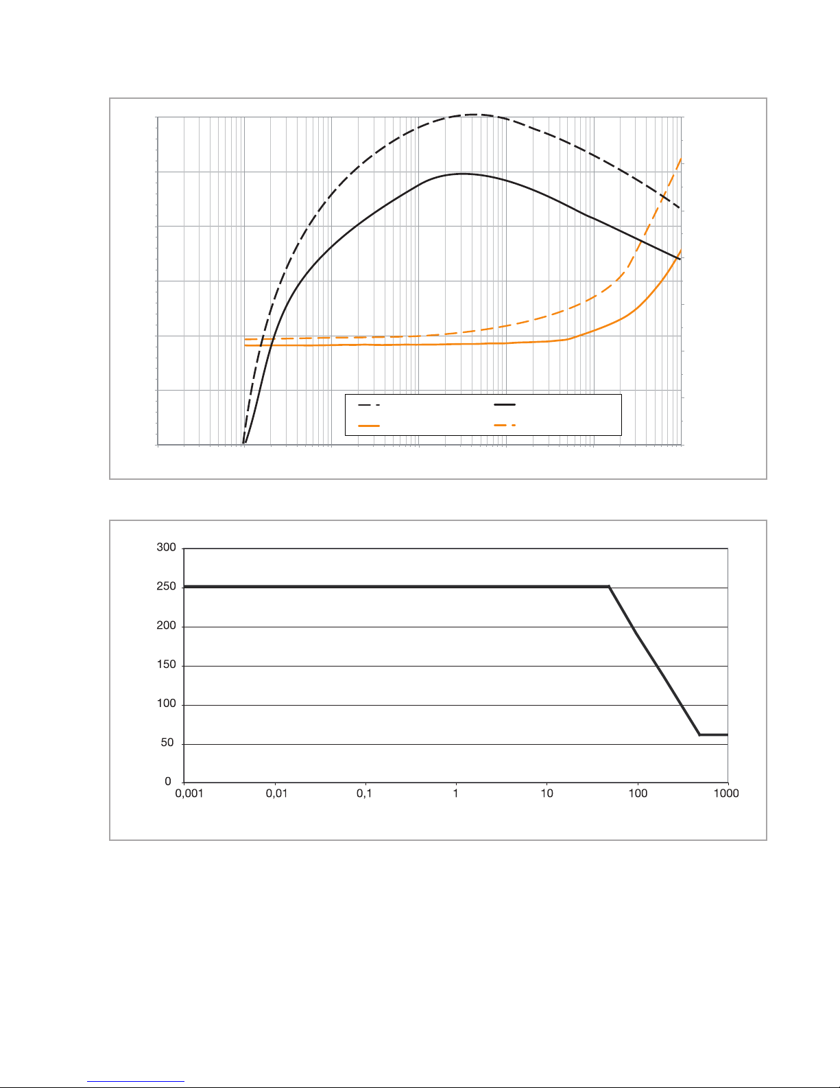
Fig. 1.8 Pumping Speed Curves for LEYVAC LV 250
0
0.001
300
200
100
250
150
50
1
60 Hz Pump Speed Air 50 Hz Pump Speed Air
50 Hz Power Air 60 Hz Power Air
Power Consumption [kW]
Pumping Speed [m
3
/h]
Inlet Pressure [mbar]
LEYVAC LV 250
0.01 0.1 10 100 1000
14
2
8
12
10
6
4
0
Fig. 1.8a Permissible gas inlet temperature as function of the inlet pressure
Gas inlet temperature (°C)
Inlet pressure (mbar)
Page 20

Description
20
300407956_002_C1 - 01/2017 - © Leybold
1.3 Technical Data
LEYVAC LV 80 140 250 Tolerance
Maximum pumping speed (50 / 60 Hz) (w/o gas ballast) 80 / 96 m3/h 125 / 145 m3/h 250 / 300 m3/h ±10 %
Ultimate partial pressure 1 x 10⁻² mbar
Max. perm. inlet pressure 1050 mbar 50 Hz: 1050 mbar
60 Hz: 1050 mbar
(temporarily);
perm.: 400 mbar
Max. perm. discharge pressure (absolute) 1300 mbar
Integral leak rate 1 x 10⁻⁵ mbarl/s
Water vapour tolerance w/gas ballast 80 slm 50 / 60 Hz 20 / 30 mbar 125 / 160 mbar 30 / 37 mbar
(at 150 slm)
Water vapour capacity w/ gas ballast 80 slm 50 / 60 Hz 1.24 / 2.3 kg/h 11.5 / 18 kg/h 6.0 / 6.3 kg/h
(at 150 slm)
Perm. ambient temperature +5 to +45 °C
Storage temperature -10 to +60 °C
Noise level with silencer, at ultimate
pressure (acc. to DIN EN ISO 2151)
< 75 dB(A)
Noise level with rigid exhaust pipe, at
ultimate pressure (acc. to DIN EN ISO 2151)
< 65 dB(A) < 72 dB(A)
Relative atmospheric humidity < 95% RH non-condensing
Installation location up to 2,500 m
Cooling Water / Glycol
Mains voltage (50 Hz) Δ200 - 220 V (Standard- & C-Version, only) / Y380 - 420 V ±10 %
Mains voltage (60 Hz) Δ200 - 220 V (Standard- & C-Version, only) / Y440 - 460 V ±10 %
Frequency 50 / 60 Hz
Phases 3-ph
Rated power at 50 / 60 Hz 4.1 kW 5.5 kW 8 kW
Rated current at 50 / 60 Hz 12 A (200 V)
6 A (400 V)
16 A (200 V)
8 A (400 V)
28 A (200 V)
16 A (400 V)
Power consumption at ultimate pressure (50 / 60 Hz) 2.9 / 3.2 kW 3.9 / 4.3 kW 4.2 / 4.7 kW
Power factor cos w (400 V; 50 / 60 Hz)
0.9 / 0.92 0.89 / 0.92 0.87 / 0.93
Max. permissible speed 4,200 rpm 3,600 rpm
Min. permissible speed 1,200 rpm
IP Code IP 54
Lubricant filling LVO 210 / LVO 410
Total lubricant quantity
(low pressure side / high pressure side)
0.8 l
(0.2 / 0.6 l)
Intake flange DN 63 ISO-K
Discharge flange DN 40 KF
Materials (components in contact
with gas in the pump chamber)
grey cast iron / steel / stainless steel / FPM
Weight, approx. 280 kg
300 kg (C & CC)
300 kg
320 kg (C & CC)
320 kg
340 kg (C & CC)
Dimensions in mm (L x W x H) 814×375×550 895×400×567 1051×425×537
Water
Water connection RC 3/8"
Water temperature +15 – 30 °C
Page 21
Description
21
300407956_002_C1 - 01/2017 - © Leybold
LEYVAC LV 80 140 250 Tolerance
Maximum supply pressure 2 – 7 bar (g)
Nominal flow
15 – 25 °C
25 – 30 °C
3 – 7 Nl/m
5 Nl/m
7 Nl/m
Materials in the cooling circuit of the pump copper, stainless steel, brass
Purge gas
Allowed purge gas N2 / Ar / dry clean air
Connection Swagelok 1/4"
Rotor purge gas flow
shaft seal
rotor purge
7 Nl / min
0 – 100 Nl / min
Permissible purge gas supply pressure 4 – 8 bar (g) (0.4 – 0.8 MPa (g))
Permissible purge gas setting pressure 1.5 – 2 bar (g) (0.15 – 0.2 MPa (g))
Optional Gas ballast (manual or electrical)
Flow (normally ambient air) 80 Nl / min
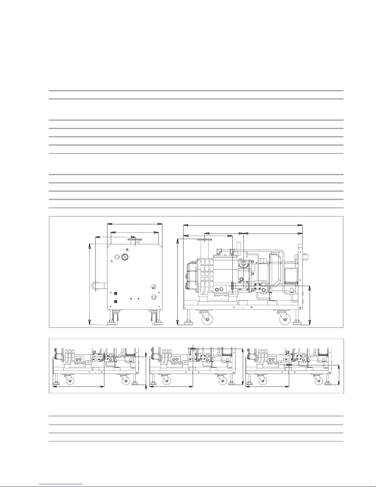
Fig. 1.9 Dimensional Drawings
C
A
B
H
G
N
P
U
V
W
Fig. 1.10 Dimensions and Exhaust Arrangements
N
Q
S
R
T
R
Modell A B C G (CC-type) H N P Q R S T U V W
LV 80 375 320 550 814 (984) 576 266 335 485 410 341 191 265 402 266
LV 140 400 350 567 895 (1065) 597 257 364 514 439 332 182 297 453 285
LV 250 425 375 537 1051 (1224) 570 230 512 662 587 305 155 420 464 285
Dimensions in mm
Page 22

Description
22
300407956_002_C1 - 01/2017 - © Leybold
1.4 Ordering Information
Part numbers for pumps
LV 80 115080V15
LV 80 C 115080V30
LV 80 C (LVO 210) 115080V40
LV 80 CC 115080V35
LV 140 115140V15
LV 140 C 115140V30
LV 140 C (LVO 210) 115140V40
LV 140 CC 115140V35
LV 250 115250V15
LV 250 C 115250V30
LV 250 C (LVO 210) 115250V40
LV 250 CC 115250V35
Accessories
Check valve ball type 115005A01
Check valve spring loaded (for noise reduction) 115005A02
RUVAC Adapter for Wx(U)501 and WH700 onto LV 80 / LV 140 115005A03
RUVAC Adapter Disc for WX1001 onto LV 140 115005A04*
RUVAC Adapter for Wx(U)501 / WH700 onto LV 250 115005A05
RUVAC Adapter Disc for WX1001 / LV 250 115005A06**
Exhaust Pressure Sensor LV 80 115005A10
Exhaust Pressure Sensor LV 140 115005A11
Exhaust Pressure Sensor LV 250 115005A09
Gas Ballast Kit manual 115005A12
Gas Ballast Kit 24V 115005A13
Purge Gas-Kit EK110003350
Standard Silencer (w/built-in check valve for noise reduction) 115005A20
High Efficiency Silencer 115005A21
Serviceable Silencer 115005A22
Drainable Silencer (w/built-in check valve for noise reduction) 115005A23
Drainable Elbow for Silencer 115005A26
Inlet screen LV 80 / LV 140 / LV 250 115005A28
Earthquake ground fixation LV 80 / LV 140 / LV 250 115005A29
Frequency converter LEYVAC LV 80 400V (incl. mains filter) 115005A30
Frequency converter LEYVAC LV 80 200V (incl. mains filter) 115005A31
Frequency converter LEYVAC LV 140 400V (incl. mains filter) 115005A35
Frequency converter LEYVAC LV 140 200V (incl. mains filter) 115005A36
Frequency converter LEYVAC LV 250 400V (incl. mains filter) 115005A40
LEYBONOL LVO 210 (synthetic oil) 1 litre L21001
LEYBONOL LVO 210 (synthetic oil) 5 litres L21005
LEYBONOL LVO 410 (PFPE) 1 litre L41001
* 115005A03 additionally required
** 115005A05 additionally required
Page 23
Transport and Storage
23
300407956_002_C1 - 01/2017 - © Leybold
2 Transport and Storage
Check the specification on the nameplate of the pump and confirm that
pump supplied agrees with your purchase.
Observe safety notes 0.1.8 and 0.1.9.
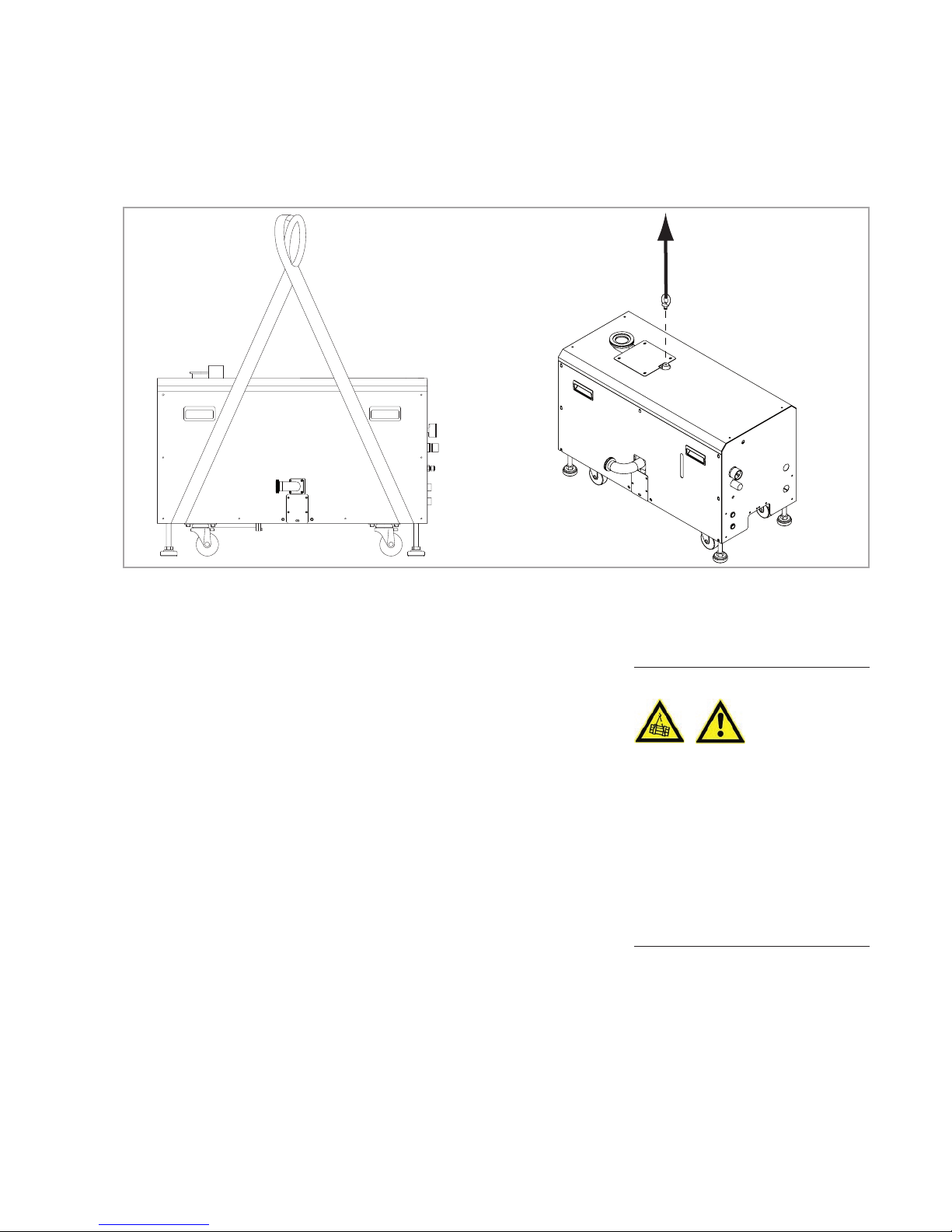
All LEYVAC LVs are equipped with a single crane eye. The pump may be
lifted with a forklift. Alternatively use two nylon slings as hoisting devices
with a length of 3 m, a width of 50 mm, and a tensile load of min. 2 tons.
Before hoisting, check if the slings are in the position between castors and
adjustment feet (cf. Fig. 2.1), to ensure the pump will not slide off. The
slings’s eyes must be centre top during hoisting, to avoid a tending to one
side. The tension for the slings should be equal at the both sides.
The pumps are supplied filled with PFPE or synthetic oil. For this reason
they should, while being transported or shipped, not be subjected to tilting
by more than 10° with respect to the horizontal axis. Store the pumps only
horizontally standing on their feet.
WARNING
Fig. 2.1 Hoisting the Pump Lifting via Crane Eye
Page 24

Transport and Storage
24
300407956_002_C1 - 01/2017 - © Leybold
Pumps with castors
Due to the castors which have been fitted, the LEYVAC must only be
installed on a level surface capable of carrying the weight of the pump as
otherwise there exists the danger of the pump rolling away. The pump must
also only be moved on level surfaces.
Moving the pump on slopes or ramps is not allowed!
The pump must only be transported using a crane.
At the installation site, use all four adjustable feet for aligning thereby securing
the unit from rolling away and thus taking away the load from the castors.
Storage
Store the pumps only horizontally standing on their feet.
When storing the pump for a longer period of time (> 2 weeks) the flanges
should be sealed off with a piece of foil. Place a bag with desiccant in the
pump chamber, if required. Before operating the pump once more do not
forget to remove this bag first.
Due to the PFPE filling pumps should be sealed off in a gas-tight manner and
vented with nitrogen.
The cooling jacket is filled with a water glycol mixture, which is cold resistant up to -10 °C.
If there is the danger of frost, the cooling water for the external water circuit must be drained, see Section 4.4 Removing from Service
Temperature -10 to +60 °C
Coolant mixture 30% glycol
Storage site dry
Maximum atmospheric humidity < 95 %, non-condensing
NOTICE
Page 25
Installation
25
300407956_002_C1 - 01/2017 - © Leybold
3 Installation
3.1 Ambient Requirements and Placement
The pump is designed for operation in buildings with a good ventilation. It
must not be installed in sites which are highly-polluted, very humid, full of
corrosive gases, and metal dust. The pump must not be exposed to direct
sunlight or water.
For maintenance purposes the clearance on top and around the pump must
be at least 900 mm.
The ambient temperature for the pump should not exceed 45 °C. The installing site should not be near boilers or any other equipment that would be
heat-radiating.
Ensure a good ventilation and heat dissipation with the pump installed
indoors; therefore the location for the vacuum pump should be considered
cautiously.
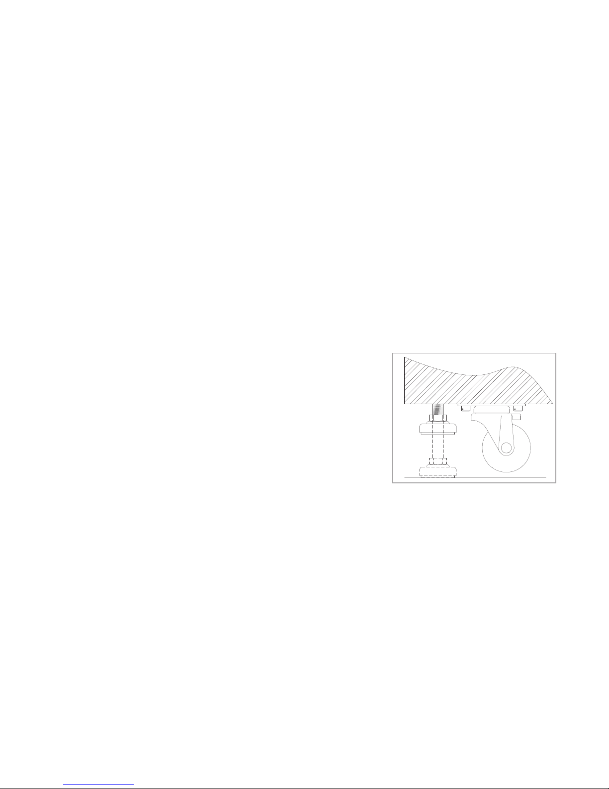
For a convenient installation, four mobile support units, each consisting of a
castor and a height-adjustment foot, are attached at the frame of the pump.
Before moving the pump, make sure to check the four adjustment feet are
already at their highest positions.
The pump should be installed on a floor which can stand the weight of the
pump. A shock-absorbing pad should be used between the frame of the
pump and the floor for a better ground holding and less impact to avoid
vibration.
Place the pump system on a flat and level surface. For proper securing
against rolling away, use all four adjustable feet for aligning thus taking away
the load from the castors.
Adjust the adjustment feet on the pump frame until the moveable wheels are
3-5 mm off the ground; then tighten the M16 nuts to fix the pump.
Remove covers and blank flanges on the pump only before fitting the pump
so that the assembly work can be performed under the cleanest conditions.
The pumps are supplied filled with PFPE (LVO 410) or synthetic oil (LVO 210).
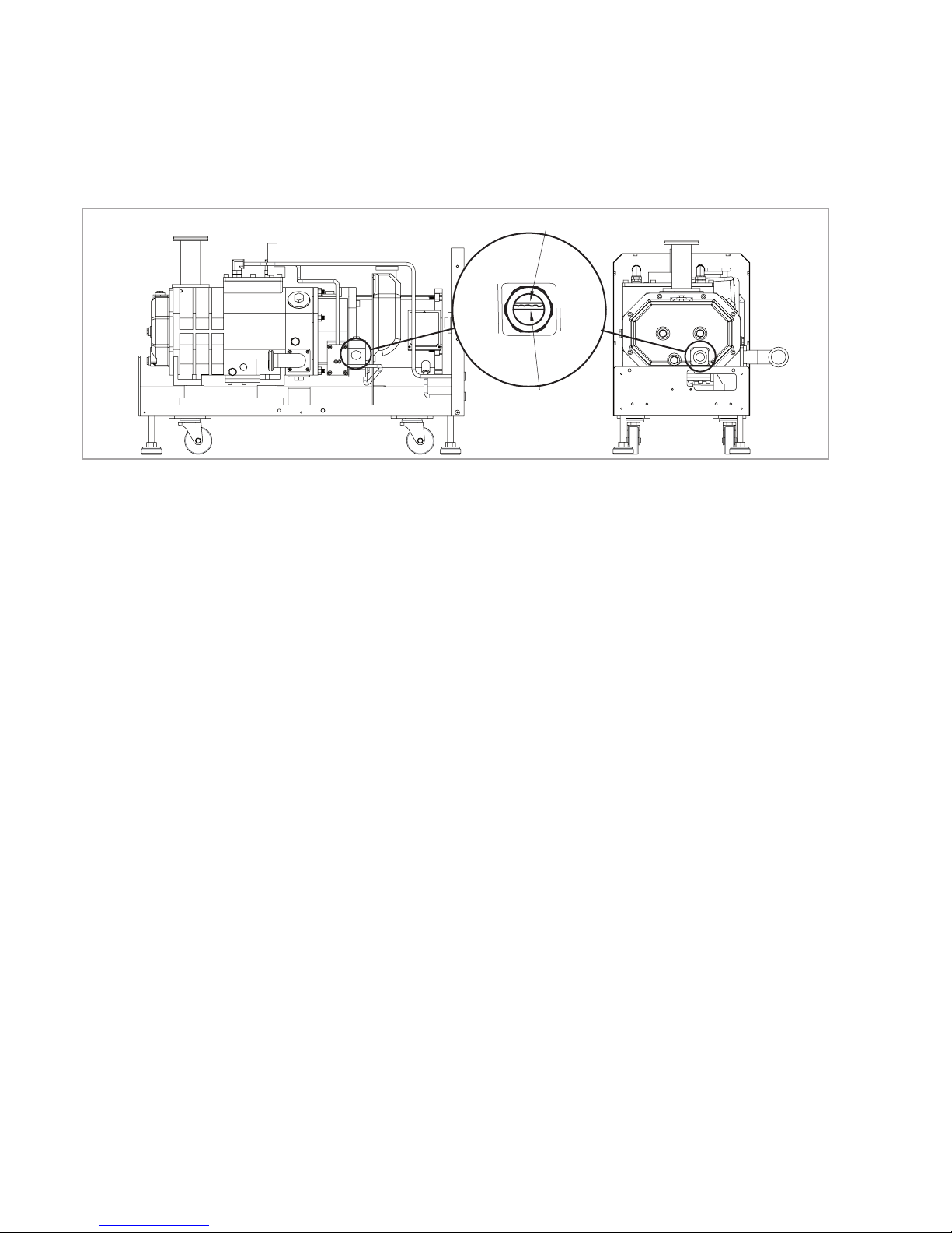
Nothing will have to be refilled. Check the oil levels through all oil level glasses. If one of the oil levels is found to be incorrect, please contact us.
The oil levels of both, the gear box and the low pressure side, should be
between 1/2 - 2/3 of the oil level glass. If the level is below 1/2, lubricant
should be added. See the Maintenance section for further information.
Fig. 3.1 Adjusting Castors
Page 26
Installation
26
300407956_002_C1 - 01/2017 - © Leybold
3.2 Conforming Use
The LEYVAC dry pumps have been developed to meet the demanding
requirements for process pumping solutions in the Coating, Flat panel,
Process and Solar industries.
Basically, all LEYVAC pumps are leaktight and may for this reason be utilised
for pumping toxic and potentially flammable gases outside their ignition
range. For such applications, note the safety information given in Section 0.4.
When using the pumps in connection with oxidising or corrosive gases,
check media compatibility first. Media compatibility and the therefrom resulting hazards of each substance used and also of each substance mixture
need to be reassessed on a case-by-case basis.
When planning to pump hazardous substances always consult Leybold first.
3.2.1 Non-conforming Use
Non-conforming use for the pump are among others:
■
Operation with limit parameters which are not programmed by Leybold,
particularly the maximum speed.
■
Pumping of gases and vapours for which the materials of the pump are not
suited, consult Leybold. For a list of materials in contact with the process
gases, see Section 1.3 Technical Data.
■
Pumping of substances and mixtures (gases, liquids and solids) which are
rated as being explosive.
■
Pumping of condensable vapours without adequately controlling the temperature of the pump. Upon compression in the pump, these vapours may
condense or form deposits, consult Leybold.
Fig. 3.2 Oil Level Indicators Low Pressure Side
High Oil
Level
Low Oil
Level
High Oil Level
Low Oil Level
Page 27
Installation
27
300407956_002_C1 - 01/2017 - © Leybold
■
Pumping of dusts and solids without suitable screens and filters, consult
Leybold.
■
Pumping of liquids
■
Pumping of ignitable gas mixtures
■
Pumping of process gases which form hard or sticky deposits which may
cause the pump to seize.
■
The use of pump and frequency converter in the explosion hazard areas
■
Non-compliance with the described maintenance and service intervals.
■
Use in systems and pump systems in which the exhaust pressure may
increase over 1.3 bar abs.
■
Operation with an inadequately affixed pump.
■
Operation at impermissibly high gas temperatures
■
Use in systems where pump, frequency converter and cables are subjected to impact stresses.
■
Operation on movable systems or system components (locks or mobile
pump systems).
■
Use of pump, fitted ad-on components, drive electronics, flanges and
cables to climb onto the system.
■
Removing, covering or obstructing warning notices.
■
Operation outside of buildings.
■
Standstill or storing of pump and drive electronics without suitable sealing
and drying. When stored in a humid atmosphere corrosion can occur.
■
Conversions, manipulations and maintenance work by persons not authorised by Leybold.
■
Accessories which have not been specified by Leybold may only be used
after approval by Leybold.
The non-conforming use of pump and accessories may result in severe
injury or damage to the components.
WARNING
Page 28
Installation
28
300407956_002_C1 - 01/2017 - © Leybold
3.3 Connecting the Intake and Exhaust Lines
3.3.1 Intake Lines
Pay attention to the following rules when connecting the vacuum pump and
the vacuum system:
For the lowest vacuum and the best pumping speed, we suggest to use the
shortest pipe, the least elbow, if possible, with the biggest diameter to
reduce the pipe line loss.
The intake lines must be clean. Connect the intake line to the pump. We recommend using bellows on the top of the pump for vibration absorption.
Support the intake lines.
Align the bellows. Do not overstress the bellows. Too much stress on the
bellows will cause them to drop out untimely and thus leading to leaks in
the system.
Check for leaks after installing the pump. A leak may lead to a dangerous
discharge of hazardous substances or to unpredictable reactions with air
admitted into the pump.
When choosing and installing the vacuum pumps for harsh processes or for
processes of special applications, like harsh furnace process, toxic or explosive gas process, please check in advance with the engineers of Leybold;
when necessary, we suggest installing a trap at the pump inlet or outlet port
to prevent any safety accidents.
Ensure that no items like welding beads, bolts, nuts, washers, pieces of
wire, for example, enter into the inlet.
3.3.2 Exhaust Lines
Connect the exhaust line to the pump system‘s exhaust connection. Use bellows to eliminate tension and vibration in the line. If applicable the exhaust ellbow can be detached and turned in 90° angels for an exhaust transport
according to customer-specific needs (cf. Fig.1.9). In this case ensure to
retighten the 4 bolts, and to conduct a leak tightness check on the exhaust.
DANGER
NOTICE
Page 29
Installation
29
300407956_002_C1 - 01/2017 - © Leybold
The exhaust line should have the same or larger diameter than the exhaust
flange (DN 40 KF) and 2.0 mm min. thickness. The exhaust line must be able
to withstand 1.3 bar and 150 °C.
Observe the following when connecting the pump and the exhaust system:
When there is high pressure from the exhaust system, check whether the
silencer of the vacuum pump and the exhaust pipes for the facilities are
blocked or not.
When using explosive, corrosive or toxic gas for the process, the pump
exhaust system must not contact the atmosphere.
The supports must be installed under the exhaust pipe line to avoid any
leakage caused by shear strength at the connecting parts of the pipe lines.
A leak check will surely be performed after the installation of the vacuum
pump or when finding any leakage. When proceeding with the leak check for
the vacuum pump or the vacuum system, please pay attention to check any
emission of gas (moisture, residual of organic solvent) which will cause virtual
leaks of the vacuum system. The recommended maximum leak rate value for
a purge gas leakage test or other ways of test is 1x10
-5
mbarl/s.
Observe Safety Information 0.1.6 to 0.1.8.
Check leak tightness of the exhaust lines on a regular basis!
Observe Safety Information 0.4.
Keep the exhaust line free of deposits. If the exhaust flow becomes restricted, deposits could collect in the LEYVACs.
Connect the exhaust line to an abatement system with sufficient throughput,
if required by the process. The LEYVAC pumps will not be switched off automatically, when the abatement system is too small and there is an overpressure. As prevention an optional pressure sensor may be installed; in this case
provide an adequate electrical connection; cf. Section 3.7.3.
In order to prevent deposits in the exhaust lines it may be necessary to heat
the exhaust lines.
Run the exhaust line only by way of a fixed installation to the outside and/or
connected to a silencer.
NOTICE
WARNING
Page 30
Installation
30
300407956_002_C1 - 01/2017 - © Leybold
3.4 Connecting Cooling Water
Observe Safety Information 0.3.3 to 0.3.6.
Never stop supplying cooling water during the pump operation, otherwise,
the components of the pump will over-heat and can damage the pump.
According to the directions of water inlet and outlet from the pump, connect
the male and female quick joints to the front panel.
Ensure that the cooling water discharge is not constricted in any way.
Supply the cooling water and check for any leakage from the joints and the
pipe lines.
Do not connect pump cooling water loops in series. Select piping to ensure
sufficient and adequate flow through each pump in accordance with the
technical data.
The temperature of the discharged cooling water must not exceed 55 °C as
otherwise the lines will tend to calcify.
If work on the water cooling system becomes necessary and in the case of a
longer standstill or transportation, completely drain out all cooling water and
completely dry the lines (with nitrogen, for example).
Block or label the area of the cooling water and exhaust lines to prevent tripping.
3.4.1 Water Quality
In order to ensure long trouble-free operation the cooling water must not
contain any oils, greases and suspended solids. Moreover, we recommend
compliance with the following limit values:
Appearance Clear, free of oils and greases
Suspended matter < 250 mg/l
Particle size < 150 µm
Electrical conductivity < 700 µS/cm
pH value 7.0 to 9.0
Total hardness (total alkaline earths) < 8 °dGH
Aggressive carbon dioxide None, not detectable
Chloride < 100 mg/l
Sulfate < 150 mg/l
Nitrate ≤ 50 mg/l
Iron < 0.2 mg/l
Manganese < 0.1 mg/l
Ammonium < 1.0 mg/l
Free chlorine < 0.2 mg/l
8 °dH (degrees German hardness) = 1.4mmol/l
= 10 °e (degrees English hardness)
= 14 °f (degrees French hardness)
If there is the danger of frost, you may use a water glycol mixture of up to 30 %.
When using DS water/deionised water (softened or fully desalinated water) check
whether cooling system, water and materials used are suitable. For this please consult us.
CAUTION
Page 31

Installation
31
300407956_002_C1 - 01/2017 - © Leybold
3.5 Purge Gas Piping
The inlet port for the purge gas is a Swagelok 1/4” stainless connector.
Allowed purge gases are N2, Ar, or dry clean air. The pressure of the purge
gas can be adjusted by the pressure regulator to a suitable pressure, and the
range is 1.5 to 2 bar (g) (0.15 – 0.2 MPa (g)).
As Leybold vacuum pumps can be used for a variety of processes the
amount of sediments thus produced will also be different. In order to reduce
corrosion due to process gas and retard the accumulation of reaction
byproducts, adjust the purge gas pressure and flow to the appropriate values. Please refer to the information given in Section 1.3 Technical Data.
Ensure that the purge gas flow is not obstructed.
The purge gas supply should not be shut off while the pump system is
operat ing, above all especially not during shutdown and venting operations.
As the pumps are equipped with a 24V-operated magnetic valve in the purge
gas system, provide an adequate electrical connection. Ensure with switching
off the pump that the magnetic valve will be closed.
Overview of Rotor Purge Gas Throughput
Refer to the following table for the relationship between pressure regulator
turns and purge gas throughput (cf. Fig. 1.4):
at End Pressure
Knob turns 0.15 MPa
0 0
0.5 16
1 37
1.5 59
2 84
2.5 95
3 100
(all values in slm; ±3 slm)
Page 32
Installation
32
300407956_002_C1 - 01/2017 - © Leybold
3.6 Electrical Connection
Observe Safety Information 0.2.
Customers must make sure that the grounding wire is connected, and the
grounding function meets the electric rules (cf. Fig. 3.4 LHS).
Check if the voltage of the power supply is correct; and the rated current
of the NFB (No Fuse Breaker) at the customer’s site meets the values in
the table listed below.
With all types of LV pumps, too, a short-circuit protection must be installed
at the connection side.
Refer to the national and local electrical regulations, and decide the proper
specification for the wire and NFB to ensure the safety of electricity usage.
Recommended rated current of main fuse and cable sizes
The voltage for the power supply should be kept within ±10% of the rating
voltage.
DANGER
Δ200 – 220V Y380 – 460V (50/60 Hz)
Main fuse Cable Size (mm
2
) Relay (A) Main fuse Cable Size (mm2) Relay (A)
LV 80 20A 4 16 15A 2.5 10
LV 140 30A 6 24 20A 4 15
LV 250 40A 6 28 30A 4 16A
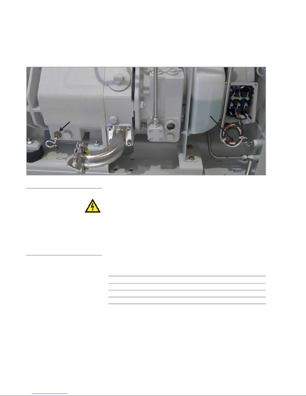
Thermal switch casing;
SW85 - white
Thermal switch
motor;
SW90 - black
PT1000 - white
Fig. 3.3 Thermal switch positions
Page 33
Installation
33
300407956_002_C1 - 01/2017 - © Leybold
3.6.1 Standard- and C-Type Pumps
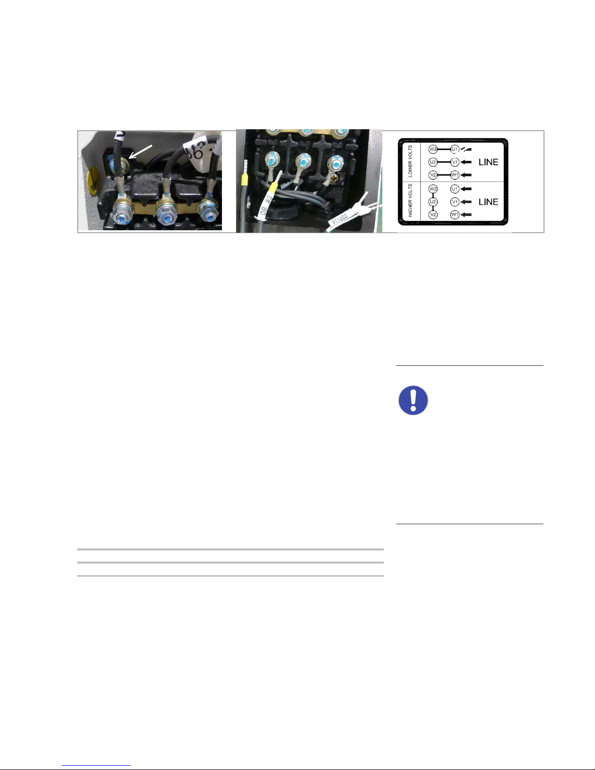
Figure 3.4 (RHS) shows the mains connecting methods for different voltages.
The terminal is designed for voltage ranges of 200 – 220V (cf. upper array),
or 380 – 420V (50 Hz) and 420 – 460V (60 Hz) (cf. lower array).
The LEYVAC has no switching devices of its own. Install an adequate motor
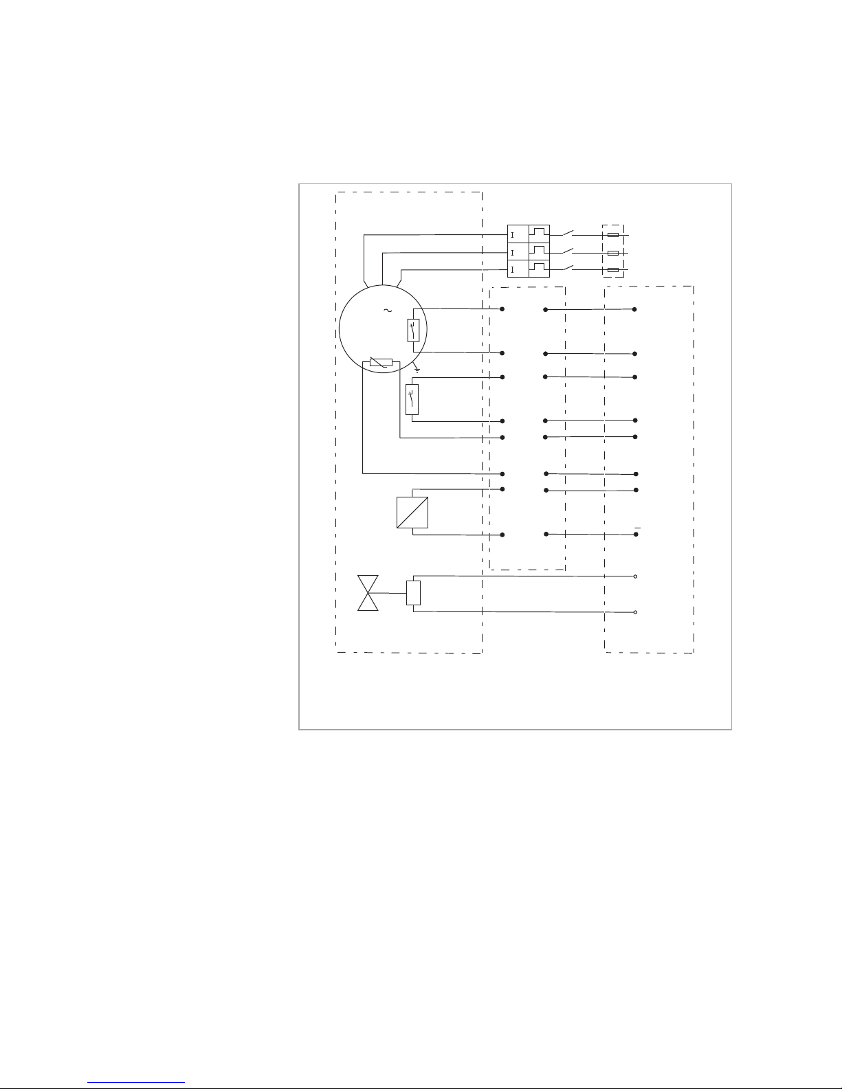
protection switch for the equipment. The pumps are equipped with two thermal switches for motor and casing protection, and a Pt1000 sensing device
for measuring the motor’s temperature (cf. Fig. 3.3).
The motor must only be operated with an overprotection circuitry in
place.
Connect the factory-integrated Pt 1000 temperature sensor, and the thermal switch of the casing (SW85) to the protection circuit of the equipment,
to prevent pump damage.
The Pt1000 serves the purpose of thermally monitoring the water-cooled
motor. It is recommended to set a warning and a shut down at temperatures of 85 °C and 100 °C, respectiviely, to protect the pump in case of
unsufficient cooling water qualities or flow rates. The thermal switch of the
motor (SW90) can be used as an alternative to the Pt 1000, if fresh water
with sufficient pressure is used as coolant.
Refer to the table below for the trigger temperatures.
Electric Device (cable) Status Action Temperatures Reset Temperatures
Motor Thermal Switch (black) NC 90 °C 50 – 60 °C
Casing Thermal Switch (white) NC 85 °C 45 – 65 °C
NOTICE
Fig. 3.4 Electrical connections: PE grounding, Thermal switch (motor) and PT 1000, and motor wiring
PE
200V
400V
Page 34
Installation
34
300407956_002_C1 - 01/2017 - © Leybold
LEYVAC LV 80 / 140 / 250
Control Unit
prov. by
customer
>>
>>
>>
F 2 F 1
L 2
L 1
L 3
Exhaust
Pressure
Sensor
(optional)
p
=
Purge Gas
24V DC
Thermal
Switch
Casing (white)
M
3
Pump
24V DC
85V AC min. 50mA
250V AC max. 2.5A
24V DC
85V AC
min. 50mA
PT1000
(white)
+
–
ϑ
Output 1 -5V
Supply 9 - 30V
< 5mA
24V DC
85V AC min. 50mA
250V AC max. 2.5A
Thermal
Switch
Motor (black)
Fig. 3.5 Main and Control Circuit Wiring (without frequency converter; non-CC-pumps)
PT1000
processing
Page 35
Installation
35
300407956_002_C1 - 01/2017 - © Leybold
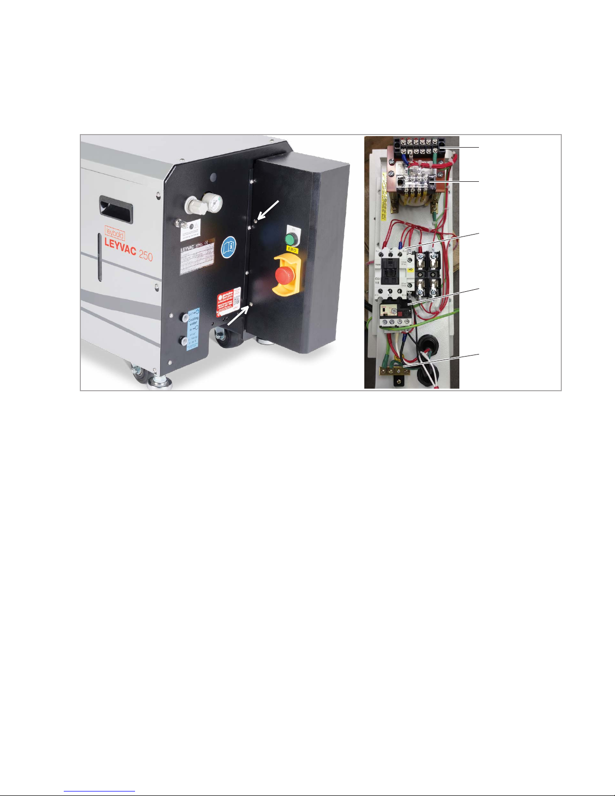
Fig. 3.6 Mains wiring for CC-type pumps
Input voltage
Transformer TR1
Mains feed
Motor protection
switch
GND
3.6.2 CC-Type Pumps
Loosen the 2 screw on each side of the terminal box (cf. Fig. 3.6). Then
remove the box cover. Connect the mains as depicted. Re-attach the cover
and tighten the screws. CC-type pumps are designed for 380 – 460V currents only.
CC-type pumps are equipped with an EMO to enable the user to turn off the
pump in case of an emergency. The EMO signal may be accessed via the
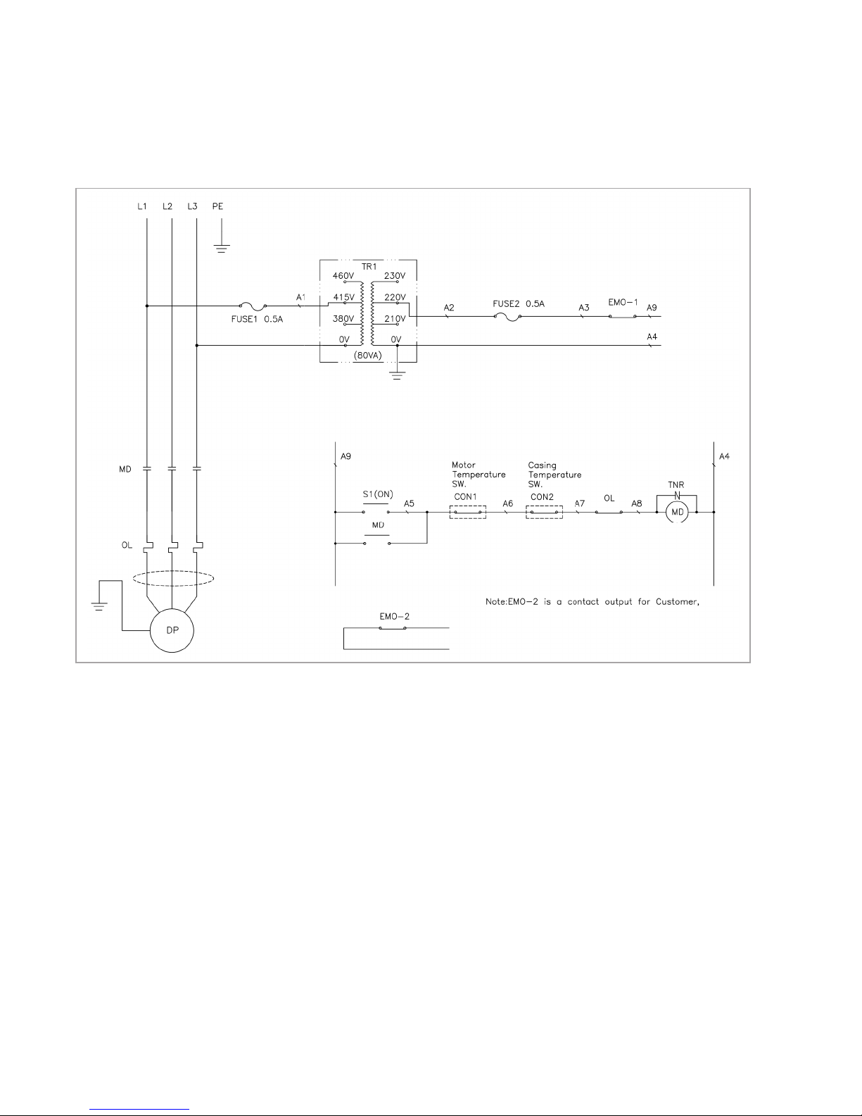
potential-free contact EMO-2 (cf. circuit diagram, Fig. 3.7) for further use
within the customer provided control unit.
The CC pump’s thermal switches are monitored by the integrated protection
circuit cutting off the motor in case of overheating. There is no need for rewiring, as the motor protection switch has already been pre-configured. By triggering the motor protection switch or the EMO the pump will be deenergised
and must be restarted after troubleshooting.
The factory-integrated Pt 1000 temperature sensor (white cable) represents
an additional means for the operator to monitor the pump (recommended
warning at 85 °C; shut down at 100 °C; cf. Fig. 3.5).
CC-type pumps are equipped with a regulating transformer for dual voltages.
Select the corresponding feed terminals A1 at the regulating transformer TR1
depending on the voltage range used: 380 – 420V: terminal 415V; 420 –
460V: terminal 380V.
Page 36
Installation
36
300407956_002_C1 - 01/2017 - © Leybold
Fig. 3.7 Main and Control Circuit Wiring (CC versions only)
* For pump operation in 460 V / 60 Hz nets the input connection of Transformer (A1) has to
be changed by trained staff from 415 V to 460 V. Output connection of Transformer (A2) stays
unchanged.
*
Page 37
Installation
37
300407956_002_C1 - 01/2017 - © Leybold
3.6.3 Checking the Direction of Rotation
The rotational direction is correct, when there is pressure at the exhaust and
the attached plastic cap fixed to the exhaust is blown off, after the pump has
been test-switched on.
3.6.4 Connecting an external Frequency Converter
Observe Safety Information 0.2.
Take note of the information provided in the manufacturer’s Operating
Instructions enclosed with the frequency converter Read these Operating
Instructions and make yourself comfortable with the contents before installing and operating the frequency converter or before doing maintenance
work on it. The frequency converter must be installed in agreement with
the information given in these Operating Instructions and in agreement with
the locally applicable regulations. Non-compliance with the safety information can result in severe or even deadly injuries or may damage the products or facilities and systems operated in connection with the product.
Enclosed with the frequency converters delivered by Leybold is a copy of the
instructions for commisioning the Yaskawa V1000. This frequency converter
shows an integrated mains filter and perfectly matches the pump.
P/N. for LEYVAC
115005A30 LV 80, 4.1 kW, 400 V
115005A31 LV 80, 4.1 kW, 200 V
115005A35 LV 140, 5.5 kW, 400 V
115005A36 LV 140, 5.5 kW, 200 V
115005A40 LV 250, 11 kW, 400 V
■
Connect the pump to the correct mains voltage through the connections in
the junction box (cf. Fig. 3.3).
■
Do not connect the electric control circuitry to the power circuitry of the
frequency converter.
■
Use fuses recommended in Main Circuit only, cf. the section Technical
Data.
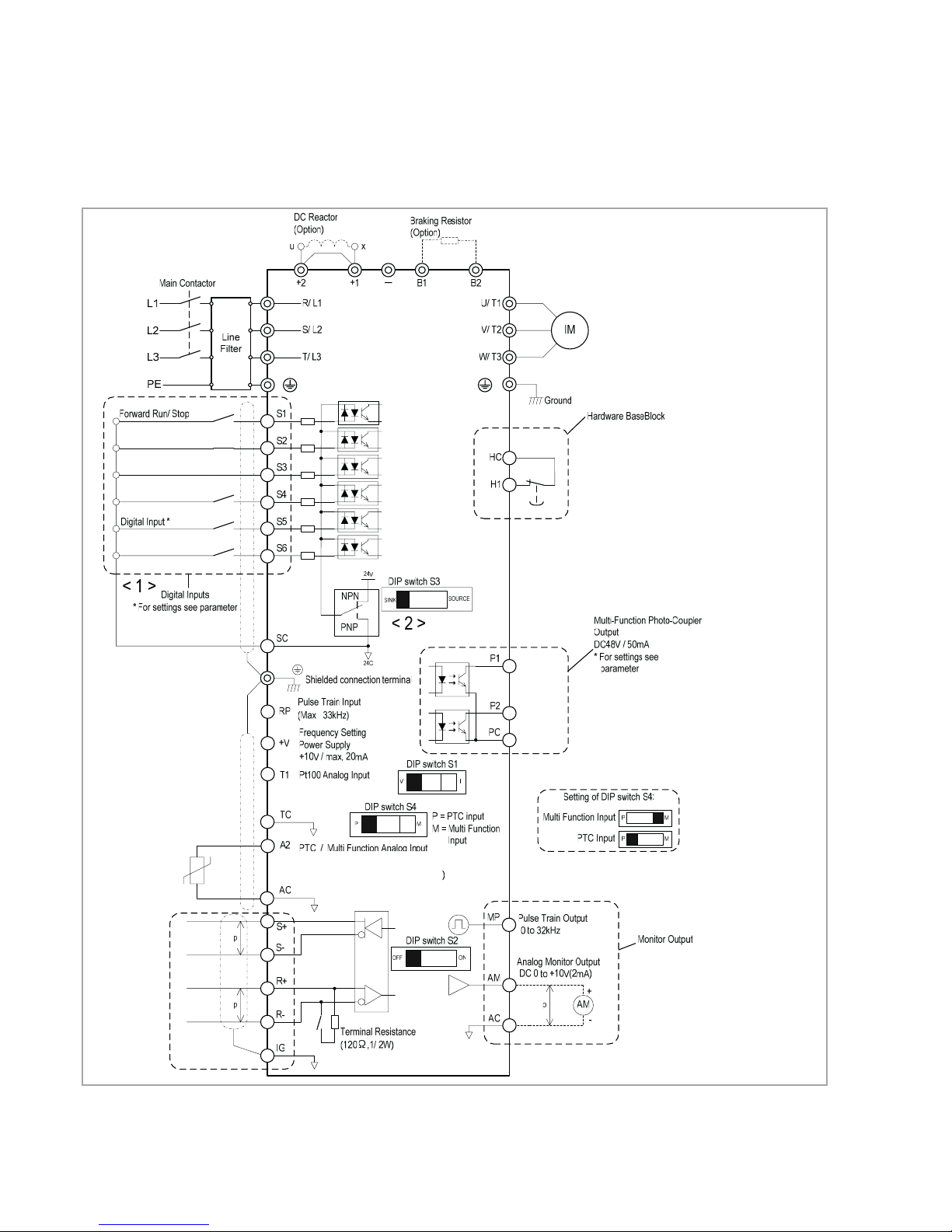
Connect both thermal switches as shown in Fig. 3.8 to ensure that the pump
is shut down as soon as one of the monitoring facilities responds:
■
Connect the casing’s thermal switch (nc; trigger 85°C) to inputs S2-SC and
■
the motor’s thermal switch (nc; trigger 90°C) to inputs S3-SC of the FC.
Shielded types of cable must be used for the motor power supply line.
The max. length for the cable between external frequency converter and
motor is 30 m.
WARNING
Page 38
Installation
38
300407956_002_C1 - 01/2017 - © Leybold
Fig. 3.8 Wiring of the main and control circuits for LEYVACs w/ external frequency converter
<1> Connected using
sequence input signal
(S1 to S6) from NPN
transistor. Default: sink
mode (0V com).
Fault reset*
PTC
Digital
Output
Warning*
Digital
Output
Failure*
Baseblock
Thermal switch casing
Thermal switch motor
Do not use the “Hardware Baseblock“
input for any functional safety in accordance to IEC 61508 or ISO/EN
13849 on your machine. For details
contact Leybold.
<2> Use only the +24V internal power supply
in sinking mode. The source mode requires
an external power supply.
DIP switch S4 changes the functionality of analog input A2. When DIP
switch S4 is set to “P“ the function is
PTC input. When DIP switch S4 is set
to “M“ the function of analog input A2
is multi-function input.
Page 39
Installation
39
300407956_002_C1 - 01/2017 - © Leybold
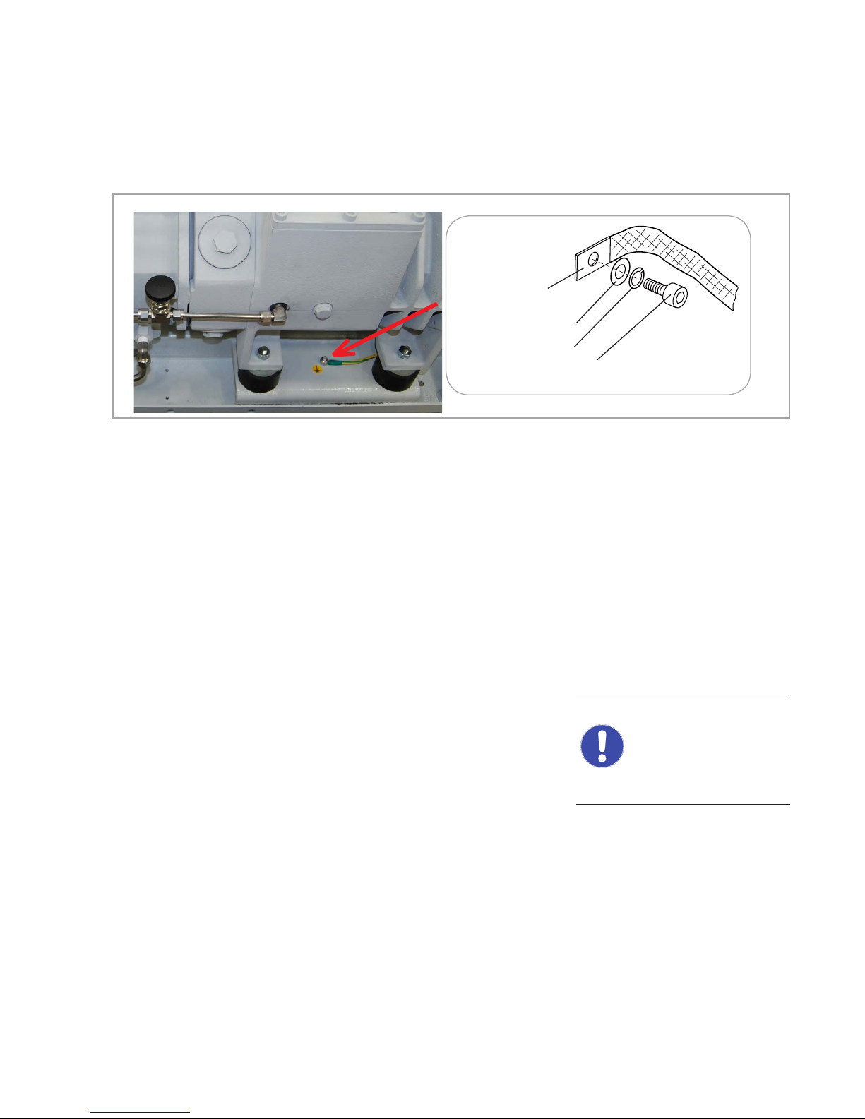
Fig. 3.9 Establishing the potential equalisation at the pump casing
Washer
Lock washer
Hexagon socket screw M 10
Copper strap, for example
In the case of FC operation considerable electromagnetic interference occurs.
Here the limits specified in the pertinent standards and guidelines need to be
complied with under all circumstances by the installer. In order to reduce the
level of electromagnetic interference, shielded motor cables, shielded cable
feedthroughs, mains filters and EMC compliant ground connections are
required between frequency converter and pump.
In order to protect the pump, current limits in the frequency converter as a
function of the frequency must be taken into account.
Permissible frequencies range
The permissible frequencies range for LEYVAC pumps is between 20 Hz
to max. 70 Hz, except for the LV 250 it is between 20 Hz and 60 Hz.
Establishing Potential Equalisation
In the case of operation with a frequency converter and ground leakagecurrents of over 3.5 mA, the protective ground conductor must have
across-section of the least 10 mm2. Or a further protective ground conductor having at least the same cross-section as the connection cable must
be provided.
A M10 thread is provided at the motor casing for connecting the external
potential equalisation cable.
The potential equalisation conductor must be connected as depicted
in Fig. 3.9.
After connecting the motor and every time you alter the wiring, check the
direction of rotation (cf. Section 3.6.3 for more information).
NOTICE
Page 40
Installation
40
300407956_002_C1 - 01/2017 - © Leybold
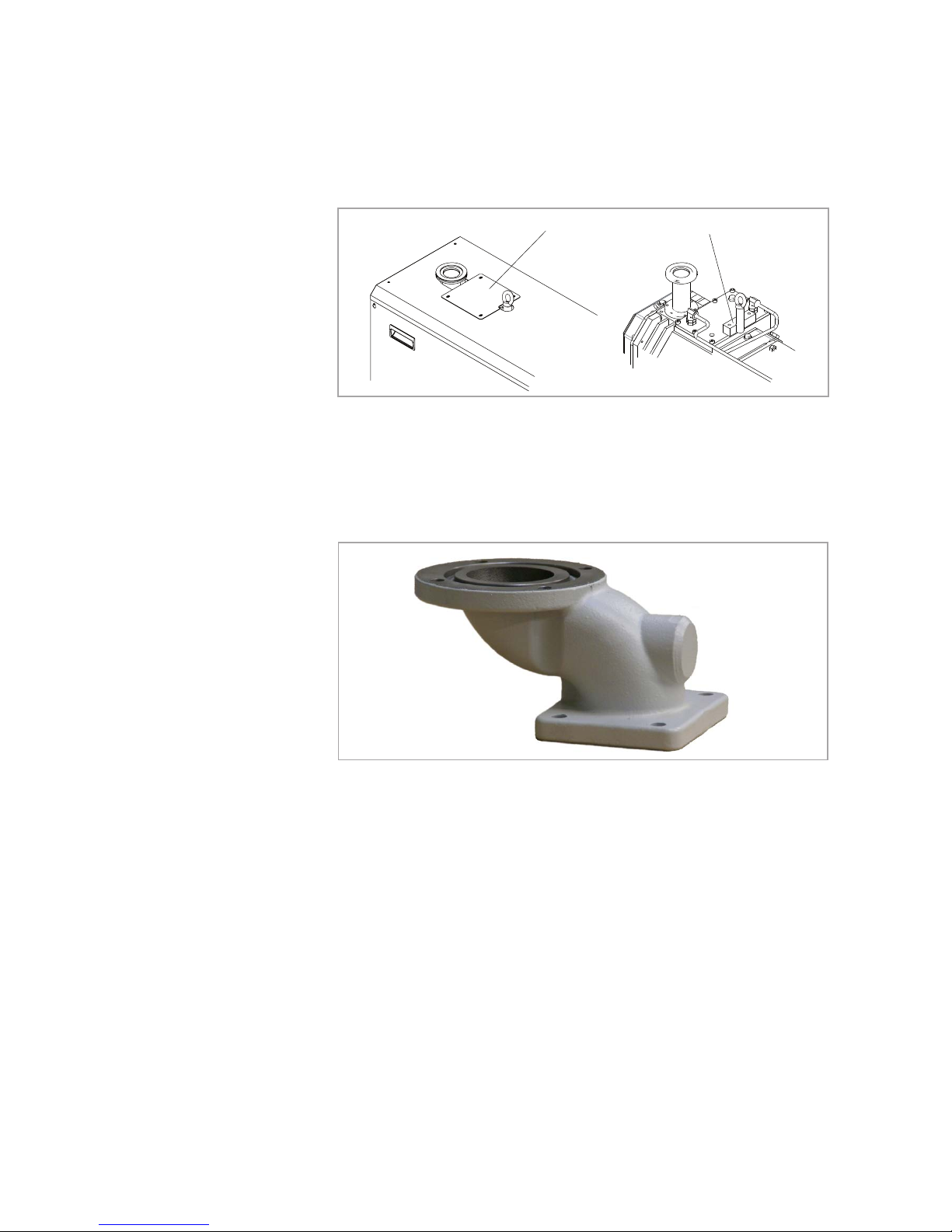
Cover
Transport Block
Fig. 3.10 Preps for Mounting a RUVAC
3.7 Mounting Accessories
C- and CC-type pumps only show a detachable cover on the housing lid.
For mounting a RUVAC remove this cover first, and then the lid. With this
modification the transport block does not have to be removed.
Fig. 3.11 RUVAC Adapter for Wx(U) 501 and WH 700 similar
3.7.1 Roots Pump Adapter
The adapter serves as a connecting component when fitting a RUVAC onto
the LV models. The use of other pump types or other connection components is not permissible. The adapter for the RUVAC weighs approximately
6kg.
Before the adapter can be mounted the stainless steel pump inlet must be
removed. Keep this gasket and the 4 screws for re-use. The RUVAC adapter
comes with 4 substitute screws; the RUVAC comes completely with bolts,
washers, nuts and gasket.
Page 41

Installation
41
300407956_002_C1 - 01/2017 - © Leybold
Fig. 3.12 LEYVAC with RUVAC WH 700 on top
Installation
Make sure that no items like welding beads, screws, nuts, washers, small
pieces of wire, for example, enter through the inlet into the pump. Carefully
handle the sealing surfaces and keep them clean.
We recommend that two fitters fit the adapter.
The Roots vacuum pump must only be fitted as depicted. Other orientations
are not allowed as otherwise stability is endangered.
Supplied Equipment
■
Adapter
■
4 hexagon socket screws M 8x25
■
O-ring 80x5, 4 stud bolts M 12x50, 8 washers A 13, 8 nuts M 12 (for fastening the RUVAC)
NOTICE
Page 42

Installation
42
300407956_002_C1 - 01/2017 - © Leybold
Mounting the adapter on the LEYVAC
C- and CC-type pumps: Firstly remove the cover and the housing lid.
When fitting the adapter onto the LEYVAC, ensure that the O-ring will not
slip.
Place the O-ring on the inlet of the LEYVAC and bolt the adapter onto the
pump, tightening torque 50 ± 5 Nm.
C- and CC-type pumps: Re-fit the housing lid, before mounting the
RUVAC.
Mounting the RUVAC
When fitting the RUVAC onto the adapter, ensure that the gasket will not slip.
Place the O-ring in the adapter groove and attach the RUVAC to the adapter,
Push the studs through the flanges and secure both ends with the nuts,
tightening torque 50 ± 5 Nm.
After fitting the adapter, we recommend conducting a leak search. For commissioning the pump combination please note the information given in the
Operating Instruction for the RUVAC.
3.7.2 Non-return Valve and Silencers
The non-return valve is a fitting for shutting off which is attached to the
ex haust flange for the LEYVAC. It prevents gas from flowing back into the
pump.
If the pump is to be connected directly to the exhaust piping, we recommend
the use of a spring-loaded valve which can be mounted in either direction.
For extremely dusty processes, we recommend the use of a self-cleaning
ball-type valve. This must only be mounted vertically.
The standard silencer comes with a built-in non-return valve which operates
both vertically and horizontally.
For processes involving much condensate there are two options for fitting the
silencer. All silencers may be fitted vertically only in combination with a drainable elbow (cf. Section 1.4).
With a horizontal version the supplied elbow can be used; in this case the
serviceable silencer must be attached, to ensure that the ball valve is the
lowest point of the exhaust system.
Page 43
Installation
43
300407956_002_C1 - 01/2017 - © Leybold
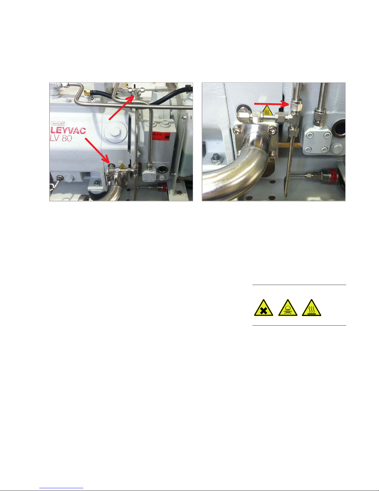
Fig. 3.13 LEYVAC 80 with optional exhaust pressure sensor Fig. 3.14 Position of the orifice plate to be inserted
3.7.3 Exhaust Pressure Sensor (option)
An exhaust pressure sensor may be installed optionally above the elbow. This
sensor is purge gas protected; the connection is provided by the customer.
At a pressure of 0 bar (g) the output voltage is 1 VDC; with a pressure of 1
bar (g) it is 5 VDC. For more information on connecting the sensor refer to
the manufacturer’s specs. The pump must be turned off with an exhaust
pressure of 0.3 bar (g).
Before starting any installation work on the pump, shut down the system
and leave it to cool down.
In particular observe Safety Information 0.3 and 0.4.
Retrofitting must only be carried out by duly trained personnel. The electrical connection must only be provided by a trained person.
The conversion kit consists of the exhaust pressure sensor as well as all necessary pipes, T-pieces, and fittings.
Only C-an CC-type pumps: Remove the top and side covers.
Remove the plug above the elbow and screw in the corresponding threaded
connector of the exhaust pressure sensor kit. Use Loctite 542 to ensure for
leak tightness. At the upper tee remove the blank flange from the shaft seal
purge gas pipe. Connect all pipes and tees as shown above. Make sure to
insert the orifice plate into the riser of the lower tee.
DANGER
Page 44
Installation
44
300407956_002_C1 - 01/2017 - © Leybold
Provide an adequate electrical connection for the sensor; refer to the wiring
schematics in the Section “Checking the Direction of Rotation”.
Systematically check for leaks after the installation, and before starting the
pump system.
Only C- and CC-type: Conduct a leak test before re-fitting the covers.
3.7.4 Gas Ballast Kit (option)
As options, LEYVACs can be retrofitted with an electrically (24 VDC) or a
manually operated gas ballast system. These conversion kits modify the conventional rotor purge gas line (A). Via these systems ambient air as the gas
ballast can be supplied at a fairly high throughput of up to 80 Nl/m. The 24
VDC valve is nc.
With the LEYVAC LV 250 with installed gas ballast kit pumped / process
gas can leak into the pump’s surrounding area via the gas ballast port. Due
to the high compression inside the pump this is the case with inlet pressures >150 mbar.
When pumping dangerous, flammable, or toxic gases the gas ballast kit of
the LEYVAC LV 250 must not be used!
The gas ballast conversion kit contains all of the necessary modification
parts.
Only C- and CC-type pumps: Remove the side cover.
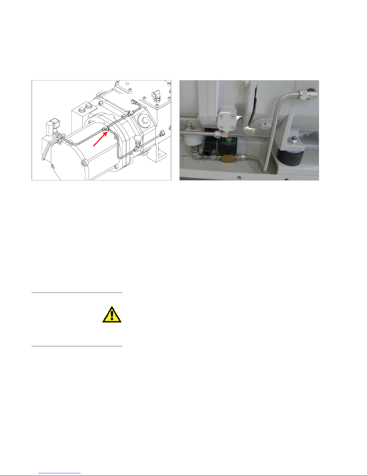
Fig. 3.16 LEYVAC with gas ballast kit installed (24 V)Fig. 3.15 Purge gas lines
Rotor Purge (A)
Purge (B)
WARNING
Page 45

Installation
45
300407956_002_C1 - 01/2017 - © Leybold
Conversion to manually operated system
Remove the purge gas pipe between the lower T-piece connection and the
manual valve. Blank-flange (included) the T-piece (cf. arrow in Fig. 3.15).
Conversion to 24 VDC system
Remove the purge gas line (A) between the lower T-piece connection and the
threaded connector at the purge gas entry (rotor). Blank-flange (included) the
T-piece, to ensure for a continuous purge gas flow to the shaft (line B).
Install the gas ballast kit, as depicted. Use Loctite 542 to ensure for leak
tightness.
Provide an adequate electrical connection for the valve (cf. to the wiring
schematics).
Check the compatibility with the media being pumped.
Systematically check for leaks after the installation, and before starting the
pump system.
Only C- and CC-type: Conduct a leak test before re-fitting the cover.
Check the gas ballast filter contamination on a regular basis.
Page 46
Operation
46
300407956_002_C1 - 01/2017 - © Leybold
4 Operation
Observe Safety Information 0.6.
4.1 Before Starting
Proceed with the following items before connecting the vacuum pump with
the power cable.
■
Check if the vacuum pump is in its position, and the adjustment feet are
fixed.
■
Turn on the cooling water flow, and check piping for water leaks.
■
Operate the pump with purge gas at all times.
For purge gas operations:
Check that the pressure regulator on the front panel is closed, i.e. the
pressure adjustment knob is fully counterclockwise. Turn on purge gas
supply. Adjust the pressure slowly to 1.5 bar (0.15 MPa), then lock the
knob. The manometer might be damaged while the purge gas supply
pressure is too large.
NOTICE
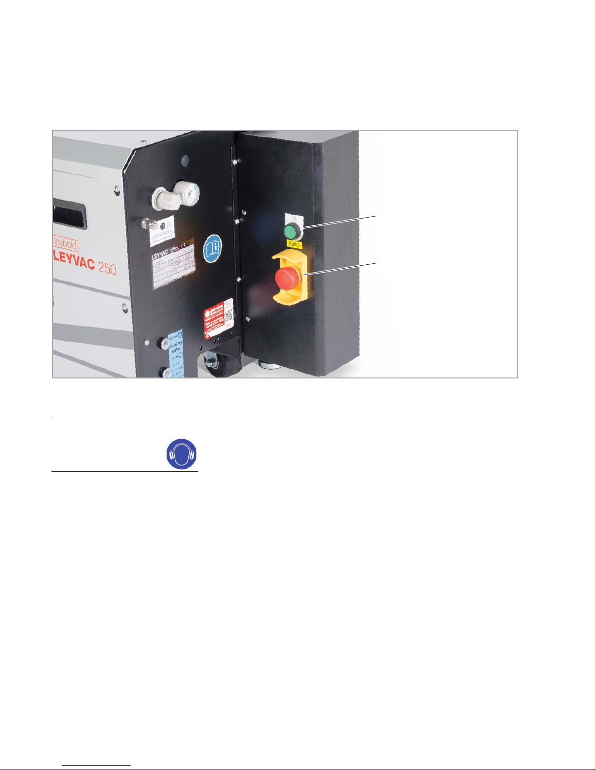
Fig. 4.1 CC-type pump’s main switches
ON
EMO
Page 47
Operation
47
300407956_002_C1 - 01/2017 - © Leybold
■
Check the exhaust piping. If there is any valve closed on the exhaust piping, open it.
■
Check that the 24V valve is opened before starting to ensure a shaft seal
purge flow.
■
Check that the manual rotor purge is opened or closed, depending on the
requirements of your applicaiton.
■
Check if the inlet port of the pump and the vacuum system are connected
properly.
■
Check the connection between the thermal switches of motor and casing
to the protection circuit of the whole equipment.
■
Check that the voltage of the power supply is correct; turn on power.
■
CC-types only:
Push the ON button, to start the pump; unlock the EMO first, if applicable.
■
Adjust the flow regulator in the N2 piping, until the flow is suitable.
If the water flow is too low, the temperatures of the pump body and the
motor will rise, and may cause rotor contact and other problems.
If the purge gas flow is too low, it can cause oil backstream, pump corrosiveness and byproducts.
CC-types only:
CC-type pumps are equipped with an EMO to enable the user to turn off
the pump in case of an emergency. The EMO signal may be accessed via
the potential-free contact EMO-2 (cf. circuit diagram, Fig. 3.7) for further
use within the customer provided control unit.
The EMO is not intented to be used as a regular switch for turning
off the pump !
4.1.1 Pumping of monoatomic Gas
Due to the higher adiabatic exponent K with monoatomic gases (e.g. argon)
and resulting higher compression temperatures please consult with the corresponding customer service before pumping these gases to evaluate your
application.
CAUTION
NOTE
Page 48

Operation
48
300407956_002_C1 - 01/2017 - © Leybold
4.2 Stop Pump
When operation is finished switch off the pump. Proceed as follows:
Isolate the pump from the chamber but keep it running.
In order to prevent any corrosive gases or byproducts inside the pump, do
not stop the pump until after at least 30 minutes after stopping the flow of
process gases.
Switch off the pump.
In order to prevent any residual process gas inside the pump, purge with
N2 gas for at least one hour after the pump stops.
Low purge gas flow during shut-off may damage the pump.
The pump must only be vented such that atmospheric pressure is
never exceeded.
If the pump has previously pumped hazard ous gases observe Safety
Information in Section 0.4.
In order to prevent a scald accident, it is strictly forbidden to touch the
pump body, the exhaust piping and the hot N2 piping before they are cold
down completely.
Keep cooling the pump with the cooling water for at least ten minutes;
after that, stop supplying the cooling water, to prevent condensation on
the surface.
4.3 Venting
Open the vacuum system only in completely vented state and only as short
as possible. Otherwise humidity will collect on the inner surfaces. This will
then, during subsequent evacuation, result in significantly longer pump down
times until attaining the desired ultimate pressure.
If during longer downtimes the system shall remain conditioned for a rapid
pumpdown, we recommend to vent the system with dry nitrogen to atmospheric pressure and maintain it in this condition without opening it.
DANGER
Page 49
Operation
49
300407956_002_C1 - 01/2017 - © Leybold
Process pump recovery after pump failure
In the event of a process pump stopping during a process step there is risk
that the pump could contain hazardous materials, the following procedure
should be followed in order to minimise the risk to people and property.
If the pump has previously pumped hazard ous gases observe Safety
Information in Section 0.4.
■
Interlock the process valve to close when the process pump stops.
■
Vent the system with dry purge gas to atmospheric pressure.
■
Shut off the purge.
■
Disconnect the pump exhaust and fit a metal ISO / NW blanking plate.
■
Disconnect the pump inlet and fit a metal ISO / NW blanking plate.
■
Disconnect the purge gas supply and seal.
■
The pump can now be removed to a workshop for decontamination and
repair.
4.4 Removing from Service
Shut off and vent the pump system as described above.
Clean the pump system of any substances which may lead to corrosion. (e.g.
by extended purge).
Flood it with nitrogen or dry purge gas, add desiccant and seal it.
Remove the cooling water from the pump system.
Remove the cooling water hoses from the pump and drain the cool ing water.
Blow out the cooling water coils with compressed air or Nitrogen (max. 4
bar). Blow into the cooling water inlet port only.
Drain the lubricant (PFPE or synthetic oil) out of the pump (cf. Fig. 5.1).
DANGER
Drain cooling water
Drain lubricant
Page 50
Operation
50
300407956_002_C1 - 01/2017 - © Leybold
If the lubricant is drained out of pumps which have already been operated
on the process, then it may have suffered contamina tion. You must determine the nature of the hazard and take the appropriate safety precautions
before draining the lubricant. Precautions can include the use of appropriate personal protective equipment (PPE) such as gloves, respirator and/or
protective clothing, working under an exhaust hood, etc. Comply with all
safety regulations.
Label the lubricant containers according to the type of contamina tion.
Loosen the drain plug somewhat, hold drain through and bucket against the
pump. Unscrew the drain plug. Tools and bucket must be clean so as not to
further contaminate the lubricant.
Screw the drain plug with the sealing ring back in, wipe off any dripped lubricant from the casing.
DANGER
Page 51

Maintenance
51
300407956_002_C1 - 01/2017 - © Leybold
5 Maintenance
5.1 Leybold Service
Whenever you send us in equipment, indicate whether the equipment is contaminated or is free of substances which could pose a health hazard. If it is
contaminated, specify exactly which substances are involved. You must use
the form we have prepared for this purpose.
A copy of the form has been reproduced at the end of these Operating
Instructions: “Declaration of Contamination for Compressors, Vacuum Pumps
and Components”. Another suitable form is available from
www.leybold.com/ -> Documents -> Download Documents.
Attach the form to each pump.
This statement detailing the type of contamination is required to satisfy legal
requirements and for the protection of our employees.
We must return to the sender any equipment which is not accompanied by a
contamination statement.
5.2 Maintenance Intervals
See the table for the recommended maintenance intervals for the pumps.
Periodic and proper maintenance will keep the pump in a normal working
condition, and helps avoiding pump breakdowns and failures. Maintenance
intervals are process-dependent. In clean processes, you may increase the
maintenance intervals; in harsh processes, you may have to decrease them.
We recommend a service contract with Leybold.
We recommend to inspect the pump system and all components after
approximately 6 months under the process conditions. The inspection of the
components shall let corrosion attacks become apparent at an early stage
and indicate possible deposits of process dust. Depending on the findings,
changed maintenance and replacement intervals can become necessary for
specific components.
Service work Interval
Coolant level in the expansion vessel Monthly
Oil level check Monthly
PFPE level and colour Monthly
Gas ballast filter Yearly
N2 pressure regulator Yearly
N2 flow regulator Yearly
Vacuum pump bearings 5 years
Vacuum pump impeller seals 5 years
LVO 210 change (synthetic oil) Yearly
PFPE change (with clean / medium application)
5 years
Water glycol mixture 5 years
Contamination
Form
Page 52
Maintenance
52
300407956_002_C1 - 01/2017 - © Leybold
This maintenance plan is a recommendation, adjust it according to your
working conditions. With harsh processes intervals should be reduced.
General Notes on Maintenance
Any maintenance work must be performed by qualified personnel. The personnel must be familiar with the safety rules related to the pump, and must
use the suitable tools to dismantle and clean the contaminated parts.
In order to prevent any danger, don’t move or disassemble the pump
before it has stopped completely; switch off the power supply to the pump
before you start maintenance work.
The pump casing, the exhaust piping and the heating piping are extremely
hot during operation and remain hot for some time after stopping. Keep
the personnel and flammable substances away from the hot area.
Purge the pump with sufficient N2 gas, at least one hour, before removing
and cleaning the vacuum lines and exhaust piping.
There might be toxic gases or materials remain in the pump, check that
there is nothing remaining before the disassembly.
Don’t reuse any o-ring. Be careful to cleaning all flange surfaces and check
they are undamaged. Check for gas leaks after installing and maintaining
the piping.
With improper use, malfunctions or exposure to fire the pump may have
overheated. Do not touch or inhale thermal breakdown products of fluorinated materials which are present if the pump has been subject to temperatures of 260 °C and above. These breakdown products are very dangerous. Fluorinated materials in the pump may include oils, greases and seals.
Disposal of process byproducts, lubricating oil, vacuum grease and other
wastes must be in strict accordance with all local and national environmental and safety regulations. For further info see Section 7 Waste Disposal.
DANGER
Page 53
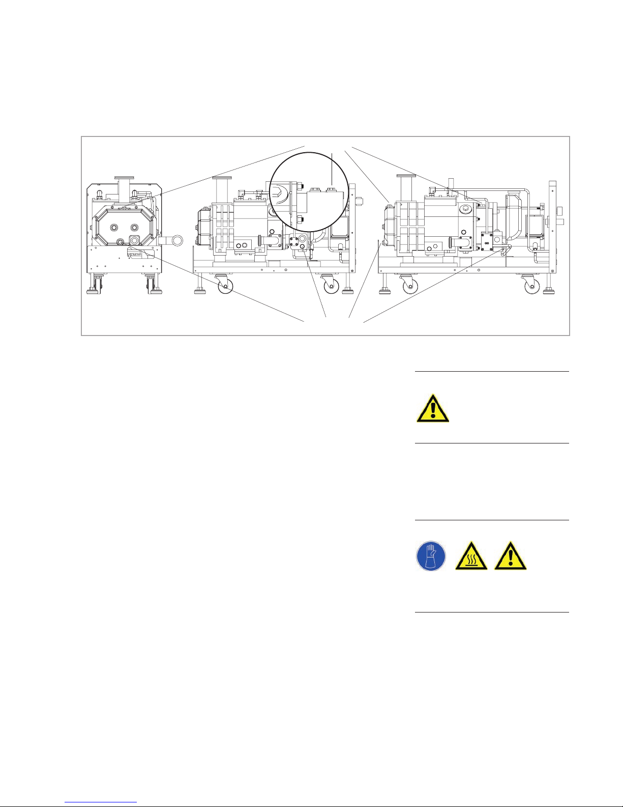
Maintenance
53
300407956_002_C1 - 01/2017 - © Leybold
5.3 Exchanging the Lubricant
Notice safety information 0.3 to 0.5.
The oil-fill port must be sealed air-tight. In the presence of a vacuum, the
entry of air may cause oil-containing gas to enter the pumping chamber via
the impeller seals.
When using PFPE as intended, PFPE is not subject to ageing. It must only be
changed if it is contaminated by the process gas. It can only be determined
individually when PFPE is so contaminated that it must be changed.
Change the lubricant more frequently when pumping corrosive vapours or
large amounts of dust or when cycling frequently from atmospheric to working pressure.
Before removing the oil-drain or oil-fill plug always switch off the pump
first and vent to atmospheric pressure.
When the pump has become warm during operation the casing and the oil
temperature may exceed 80 °C.
Leave the pump to cool down. Always wear protective gloves also to protect yourself against aggressive residues in the lubricant.
CAUTION
WARNING
Oil ll ports
Oil drain ports
LEYVAC LV 80 LEYVAC LV 140
Fig. 5.1 Positions of Oil Ports for Exchanging Lubricants
Page 54

Maintenance
54
300407956_002_C1 - 01/2017 - © Leybold
The lubricating oil for the vacuum pump is fluorinated lubricant oil (LVO 410)
or synthetic oil (LVO 210). Another kind of oil can not be used or replaced;
otherwise, it will cause a major damage of the vacuum pump. When replacing the oil, the used oil inside the pump must be drained out completely; otherwise, it will reduce the lifetime of the new oil. The procedures to replace the
oil are listed as follows:
■
Dismantle the oil fill plug at the oil inlet hole.
■
Dismantle the drain plug at the oil outlet hole; drain out the oil of the oil
box, or make use of a proper pump to draw out the used oil.
■
Replace all the O-rings. Check the drain plug is tightened. Wipe off any oil
residues from the casing.
■
Fill in new oil at a pump temperature of 15 ºC to 25 ºC.
■
Make sure to use the right kind of oil and according to Leybold’s suggestion. Only use Leybold authorized vacuum oil and re-supply the new oil.
■
Clean the oil-fill port, reinstall and tighten the plug using a gasket which is
in perfect condition. Wipe off any oil residues from the casing.
Observe the correct oil fill levels for the shutdown (standing still) pump.
The oil levels of both, the gear box and the low pressure side, should be
between 1/2 – 2/3 of the oil level glass height. If the level drops below 1/2,
lubricant should be added (cf. Fig. 3.2).
If the oil level is too low, the bearings and gearwheels are not lubricated
adequately; if it is too high, oil may enter the pumping chamber.
Mineral oils, synthetic oils and PFPE do not mix.
Please consult us if you intend to run the pump with other oils or special
lubricants.
The waste oil must be disposed by a professional and qualified waste disposal dealer, container with PFPE has to be labelled as such. For further info
see Section 7 Waste Disposal.
5.4 Exhaust Piping Connector
A regular leakage check should be performed over all the connecting parts of
the piping. It should be included of checking any crack on the pipes.
Washers, O-rings and pipes should be replaced according to their condition.
All parts should be tightened again or re-sealing if necessary.
5.5 Pump Inlet Flange
Dismantle the pump inlet flange regularly for cleaning the dirt on the mesh
and change with a new O-ring.
NOTICE
Page 55
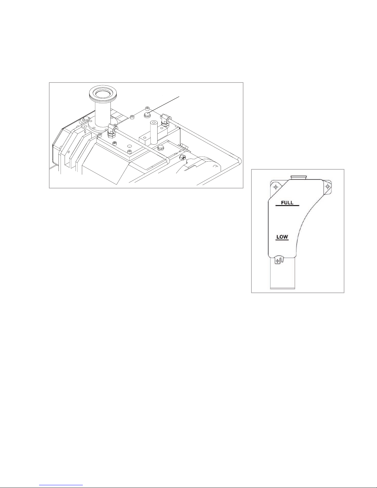
Maintenance
55
300407956_002_C1 - 01/2017 - © Leybold
Fig. 5.3 Expension Vessel
Glykoleinfüllstutzen
Fig. 5.2 Fill port for the main cooling circuit
Glycol fill port
5.6 Purge Gas Pressure and Flow Regulator
Check and test regularly that the function of the N2 pressure regulator and
the N2 flow regulator are normal. When the pump is running, supply the N2
gas and regulate the flow to check the N2 mass flow works in normal condition.
Check the gas ballast filter contamination in regards to the ambient air on a
regular basis, and replace the filter insert as appropiate.
5.7 Cooling Water Piping
After operating for a period of time, the cooling water piping might encounter
the problem of a poor cooling effect because of the dirt adhering to the piping. It will cause the pump casing temperature to rise. A regular cleaning job
is necessary, and the clean frequency is dependent on the quality of the
water. The cooling tower and the filter should also be cleaned often. If the
piping has already been adhered with the dirt, the piping should be cleaned
with a cleaner or be replaced.
5.8 Coolant Level
Check the coolant level in the expansion vessel regularly. If the coolant is
insufficient, re-supply the water-glycol-mixture and keep the level between
FULL and LOW. If the level is really low, additionally fill in coolant directly into
the main cooling circuit (cf. Fig. 5.2). The capacity of the main cooling circuit
and the expansion vessel is approx. 5 litres.
Page 56

Troubleshooting
56
300407956_002_C1 - 01/2017 - © Leybold
6 Troubleshooting
6.1 Pump Malfunctions
6.1.1 Malfunctions with CC-type Pumps
Malfunction Remedy
Thermal relay trip Reset trip (cf. Fig. 3.6)
Motor thermal switch trip Let the pump cool down (≤ 59 °C), then press the “ON”
button (CC cover) manually.
Casing thermal switch trip Let the pump cool down (≤ 70 °C ~ 40 °C), then press
the “ON” button (CC cover) manually.
6.2 Malfunctions with Frequency Converter Operations (option)
Faults and alarms indicate problems in the frequency converter or in the
pump.
An alarm (warning) is indicated by a code on the data display and the flashing
ALM LED. The frequency converter output is not necessarily switched off.
A fault is indicated by a code on the data display and the ALM LED is on.
The frequency converter output is always switched off immediately and the
motor coast to stop.
To remove an alarm or reset a fault, trace the cause, remove it and reset the
frequency converter by pushing the Reset key on the operator or cycling the
power supply.
This lists up the most important alarms and faults only.
Malfunction Likely cause Remedy
Current is too high
Exhaust pressure rises.
Pump with noise, and rotors are in contact.
Power supply failure.
Check exhaust piping and silencer.
Replace or overhaul pump.
Check power supply.
Motor temp. high (90 °C)
Insufficient cooling.
Motor failure.
Check water flow and temperature.
Replace the motor.
Casing temp. high (85 °C)
Insufficient cooling.
Insufficient coolant in the water jacket.
Byproduct is clogged.
Check water flow and temperature.
Refill the coolant.
Replace or overhaul pump.
Water flow is too low
Water piping leaks.
Differential pressure is too small
Water piping is clogged.
Outlet / inlet is reverse.
Check the fittings.
Check the inlet and outlet pressure of water piping.
Clean or replace piping.
Connect correctly.
Page 57
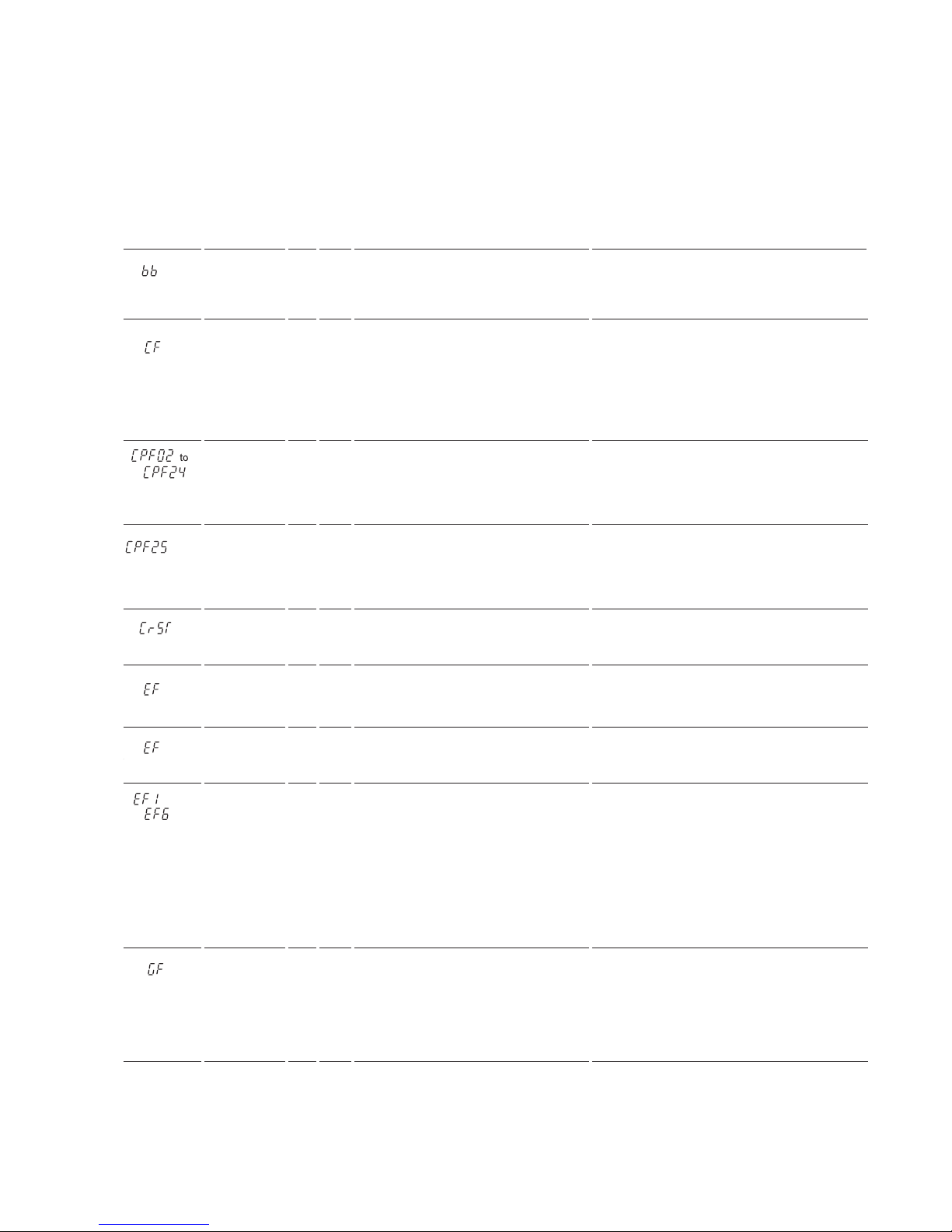
Troubleshooting
57
300407956_002_C1 - 01/2017 - © Leybold
Error
message
Brief
Description
AL FLT Possible cause Corrective Action
Base Block
n
The software base block function is
assigned to one of the digital inputs
and the input is off. The frequency converter does not accept Run commands.
Check the digital inputs function selection.
Provide link between SC and S6.
Control Fault The torque limit was reached during
deceleration for longer than 3 sec.
when in Open Loop Vector control
• The load inertia is too big.
• The torque limit is too low.
• The motor parameters are wrong.
Check the load.
Set the torque limit to the most appropriate
setting (L7-01 through L7-04).
Check the motor parameters.
Control
Circuit Fault
n
There is a problem in the frequency
converter’s control circuit.
Cycle the frequency converter power supply.
Initialize the frequency converter.
Replace the frequency converter if the fault
occurs again.
Control
Circuit Fault
n
There is no terminal board connected
to the control board.
Check if the terminal board is installed properly.
Uninstall and Reapply the terminal board.
Change the frequency converter.
Cannot
Reset
n
Fault reset was input when a Run command was active.
Turn off the Run command and reset the frequency converter.
Option
External
Fault
n n
An external fault was tripped by the
upper controller via an option card.
Remove the fault cause, reset the fault and
restart the frequency converter.
Check the upper controller program.
External
Fault
n
A forward and reverse command were
input simultaneously for longer than 500
ms. This alarm stops a running motor.
Check the sequence and make sure that the
forward and reverse input are not set at the
same time.
to
External
Faults
n n
An external fault was triggered by an
external device via one of the digital
inputs S1 to S6.
EF2: Temperatur limiter (casing rotor)
exceeds fault threshold.
EF3: Temperature limiter (motor)
exceeds fault threshold.
The digital inputs are set up incorrectly.
Find out why the device tripped the EF.
Remove the cause and reset the fault.
Check water cooling.
Check motor load, reduce if required, check
water cooling.
Check the functions assigned to the digital
inputs.
to
Ground Fault
n
Ground leakage current has exceeded
50% of the frequency converters rated
output current.
Cable or motor insulation is broken.
Excessive stray capacitance at frequency converter output.
Check the output wiring and the motor for
short circuits or broken insulation. Replace any
broken parts.
Reduce the carrier frequency.
Page 58
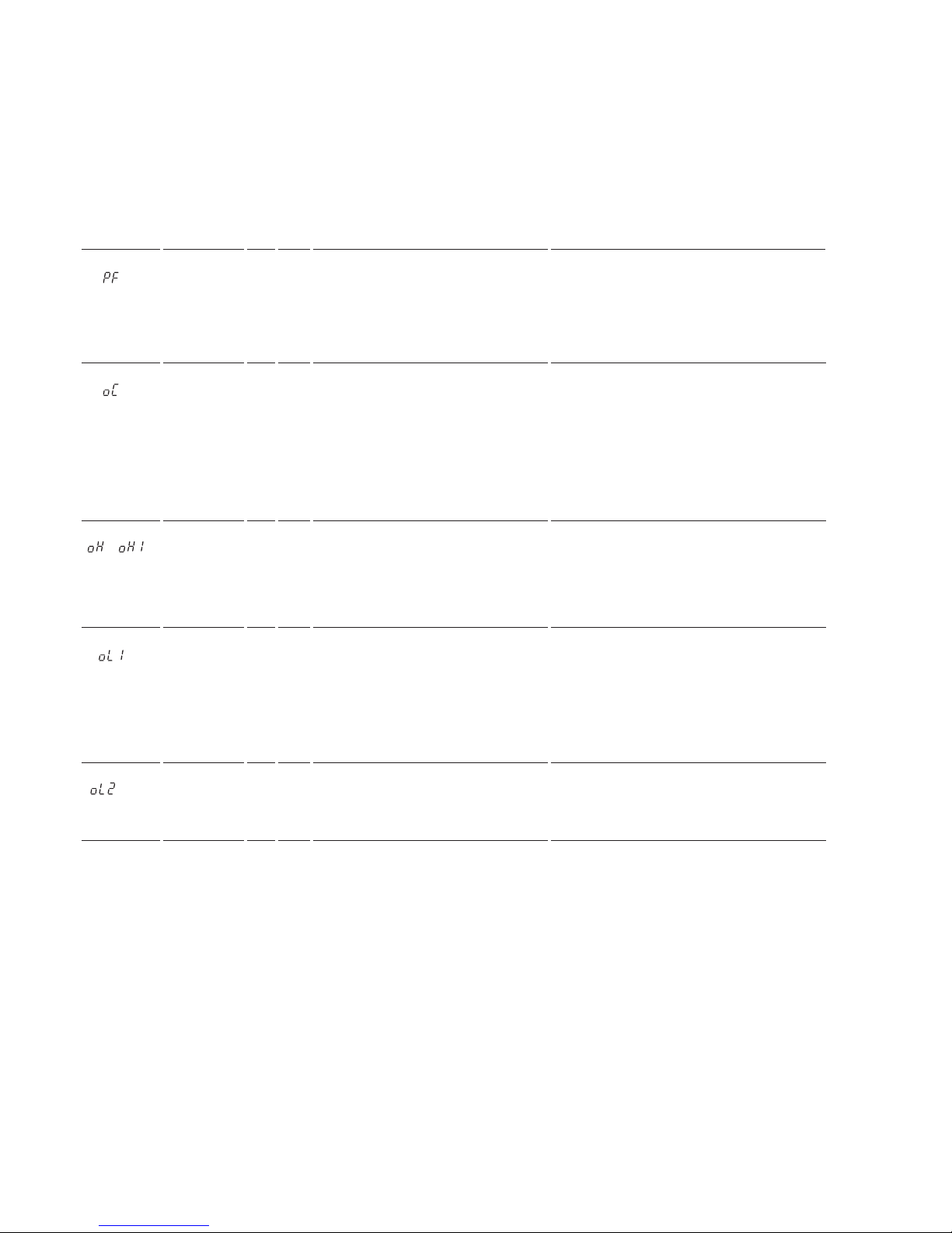
Troubleshooting
58
300407956_002_C1 - 01/2017 - © Leybold
Error
message
Brief
Description
AL FLT Possible cause Corrective Action
to
Output
Phase Loss
n
Output cable is disconnected or the
motor winding is damaged.
Loose wires at the frequency converter
output.
Motor is too small (less than 5% of frequency converter current).
Check the motor wiring.
Make sure all terminal screws in the frequency
converter and motor are properly tightened.
Check the motor and frequency converter
capacity.
to
Overcurrent
n
Short circuit or ground fault on the frequency converter output side
The load is too heavy.
The accel./decel. times are too short.
Wrong motor data or V/f pattern settings.
A magnetic contactor was switched at
the output.
Check the output wiring and the motor for
short circuits or broken insulation. Replace the
broken parts.
Check the machine for damages (gears, etc.)
and repair any broken parts.
Check the frequency converter parameter settings.
Check the output contactor sequence.
to
or
Heatsink
Overheat
n n
Surrounding temperature is too high.
The cooling fan has stopped.
The heatsink is dirty.
The airflow to the heatsink is restricted.
Check the surrounding temperature and install
cooling devices if necessary.
Check the frequency converter cooling fan.
Clean the heatsink.
Check the airflow around the heatsink.
to
or
Motor
Overload
n
The motor load is too heavy.
The motor is operated at low speed
with heavy load.
Cycle times of accel./ decel. are too
short.
Incorrect motor rated current has been
set.
Reduce the motor load.
Use a motor with external cooling and set the
correct motor in parameter L1-01
Check the sequence.
Check the rated current setting.
Drive
Overload
n
The load is too heavy.
Too much torque at low speed.
Check the load.
The overload capability is reduced at low
speeds. Reduce the load or increase the frequency converter size.
Page 59
Waste Disposal
59
300407956_002_C1 - 01/2017 - © Leybold
7 Waste Disposal
The equipment may have been contaminated by the process or by environmental influences. In this case the equipment must be decontaminated in
accordance with the relevant regulations. We offer this service at fixed prices.
Further details are available on request.
Contaminated parts can be detrimental to health and environment.
Before beginning with any work, first find out whether any parts are contaminated. Adhere to the relevant regulations and take the necessary precautions when handling contaminated parts.
Separate clean components according to their materials, and dispose of
these accordingly. We offer this service. Further details are available on
request.
When sending us any equipment, observe the regulations given in Section
5.1 Leybold service.
Disposal of Waste Oil
Owners of waste oil are entirely self-responsible for proper disposal of this
waste.
Waste oil from vacuum pumps must not be mixed with other substances or
materials.
Waste oil from vacuum pumps (Leybold oils which are based on mineral oils)
which are subject to normal wear and which are contaminated due to the
influence of oxygen in the air, high temperatures or mechanical wear must be
disposed of through the locally available waste oil disposal system.
Waste oil from vacuum pumps which is contaminated with other substances
must be marked and stored in such a way that the type of contamination is
apparent. This waste must be disposed of as special waste.
European, national and regional regulations concerning waste disposal need
to be observed. Waste must only be transported and disposed of by an
approved waste disposal vendor.
PFPE from vacuum pumps may be regenerated, if required, and provided
the quantities are large enough. For this, please contact us for assistance.
Contamination
WARNING
Page 60
60
300407956_002_C1 - 01/2017 - © Leybold
EC Declaration of Conformity
Page 61

61
300407956_002_C1 - 01/2017 - © Leybold
17200001_002_C0
© Leybold
Declaration of Contamination of Compressors, Vacuum Pumps and Components
The repair and / or servicing of compressors, va cuum pumps and components will be carried out only if a correctly completed declaration has
been submitted. Non-completion will result in delay
. The manufacturer can refuse to accept any equipment without a declaration.
A separate declaration has to be completed for each single component.
This declaration may be completed and signed only by authorized and qualified staff.
Customer/Dep./Institute : Reason for return: applicable please mark
Address : Repair: chargeable warranty
Exchange: chargeable warranty
Exchange already arranged / received
Person to contact: Return only: rent loan for credit
Phone : Fax: Calibration: DKD Factory-calibr.
End user: Quality test certificate DIN 55350-18-4.2.1
A. Description of the Leybold product:
Failure description:
Material description :
Catalog number: Additional parts:
Serial number: Application-Tool:
Type of oil (ForeVacuum-Pumps) : Application- Process:
B. Condition of the equipment
No1) Yes No Contamination : No1) Yes
11.
. Has the equipment been used
toxic
2. Drained (Product/service fluid)
corrosive
3. All openings sealed airtight
flammable
4. Purged
explosive 2)
If yes, which cleaning agent
radioactive
2)
and which method of cleaning
microbiological
2)
1)
If answered with “No”, go to D. other harmful substances
C. Description of processed substances (Please fill in absolutely)
1. What substances have come into contact with the equipment ?
Trade name and / or chemical term of service fluids and substances processed, properties of the substances
According to safety data sheet (e.g. toxic, inflammable, corrosive, radioactive)
X Tradename: Chemical name:
a)
b)
c)
d)
No Yes
2. Are these substances harmful ?
3. Dangerous decomposition products when heated ?
If yes, which ?
2)
Components contaminated by microbiological, explosive or radioactive products/substances will not be accepted without written
evidence of decontamination.
D. Legally binding declaration
I / we hereby declare that the information supplied on this form is accurate and sufficient to judge any contamination level.
Name of authorized person (block letters) :
Date signature of authorized person
firm stamp
Declaration of Contamination
Page 62

Headquarter
Leybold GmbH
Bonner Strasse 498
D-50968 Cologne
T: +49-(0)221-347-0
F: +49-(0)221-347-1250
[email protected]
Germany
Leybold GmbH
Sales, Service, Support Center (3SC)
Bonner Strasse 498
D-50968 Cologne
T: +49-(0)221-347 1234
F: +49-(0)221-347 31234
[email protected]
www.leybold.com
Leybold GmbH
Sales Area North
Branch Office Berlin
Industriestrasse 10b
D-12099 Berlin
T: +49-(0)30-435 609 0
F: +49-(0)30-435 609 10
[email protected]
Leybold GmbH
Sales Office South
Branch Office Munich
Karl-Hammerschmidt-Strasse 34
D-85609 Aschheim-Dornach
T: +49-(0)89-357 33 9-10
F: +49-(0)89-357 33 9-33
[email protected]
[email protected]
Leybold Dresden GmbH
Service Competence Center
Zur Wetterwarte 50, Haus 304
D-01109 Dresden
Service:
T: +49-(0)351-88 55 00
F: +49-(0)351-88 55 041
[email protected]
Europe
Belgium
Leybold Nederland B.V.
Belgisch bijkantoor
Leuvensesteenweg 542-9A
B-1930 Zaventem
Sales:
T: +32-2-711 00 83
F: +32-2-720 83 38
[email protected]
Service:
T: +32-2-711 00 82
F: +32-2-720 83 38
[email protected]
France
Leybold France S.A.S.
Parc du Technopolis, Bâtiment Beta
3, Avenue du Canada
F-91940 Les Ulis cedex
Sales and Service:
T: +33-1-69 82 48 00
F: +33-1-69 07 57 38
[email protected]
[email protected]
Leybold France S.A.S.
Valence Factory
640, Rue A. Bergès
B.P. 107
F-26501 Bourg-lès-Valence Cedex
T: +33-4-75 82 33 00
F: +33-4-75 82 92 69
[email protected]
Great Britain
Leybold UK LTD.
Unit 9
Silverglade Business Park
Leatherhead Road
Chessington
Surrey (London)
KT9 2QL
Sales:
T: +44-13-7273 7300
F: +44-13-7273 7301
[email protected]
Service:
T: +44-13-7273 7320
F: +44-13-7273 7303
[email protected]
Italy
Leybold Italia S.r.l.
Via Trasimeno 8
I-20128 Mailand
Sales:
T: +39-02-27 22 31
F: +39-02-27 20 96 41
[email protected]
Service:
T: +39-02-27 22 31
F: +39-02-27 22 32 17
[email protected]
Netherlands
Leybold Nederland B.V.
Floridadreef 102
NL-3565 AM Utrecht
Sales and Service:
T: +31-(30) 242 63 30
F: +31-(30) 242 63 31
[email protected]
[email protected]
Switzerland
Leybold Schweiz AG, Pfäffikon
Churerstrasse 120
CH-8808 Pfäffikon
Warehouse and shipping address:
Riedthofstrasse 214
CH-8105 Regensdorf
Sales:
T: +41-44-308 40 50
F: +41-44-302 43 73
[email protected]
Service:
T: +41-44-308 40 62
F: +41-44-308 40 60
[email protected]
Spain
Leybold Hispánica, S.A.
C/. Huelva, 7
E-08940 Cornellá de Llobregat
(Barcelona)
Sales:
T: +34-93-666 43 11
F: +34-93-666 43 70
[email protected]
Service:
T: +34-93-666 46 11
F: +34-93-685 43 70
[email protected]
America
USA
Leybold USA Inc.
5700 Mellon Road
USA-Export, PA 15632
T: +1-724-327-5700
F: +1-724-325-3577
[email protected]
Sales:
T: +1-724-327-5700
F: +1-724-333-1217
Service:
T: +1-724-327-5700
F: +1-724-325-3577
Brazil
Leybold do Brasil
Rod. Vice-Prefeito Hermenegildo Tonolli,
nº. 4413 - 6B
Distrito Industrial
Jundiaí - SP
CEP 13.213-086
Sales and Service:
T: +55 11 3395 3180
F: +55 11 99467 5934
[email protected]
[email protected]
Asia
P. R. China
Leybold (Tianjin)
International Trade Co. Ltd.
Beichen Economic
Development Area (BEDA),
No. 8 Western Shuangchen Road
Tianjin 300400
China
Sales and Service:
T: +86-22-2697 0808
F: +86-22-2697 4061
F: +86-22-2697 2017
[email protected]
[email protected]
India
Leybold India Pvt Ltd.
No. 82(P), 4th Phase
K.I.A.D.B. Plot
Bommasandra Industrial Area
Bangalore - 560 099
Indien
Sales and Service:
T: +91-80-2783 9925
F: +91-80-2783 9926
[email protected]
[email protected]
Japan
Leybold Japan Co., Ltd.
Headquarters
Shin-Yokohama A.K.Bldg., 4th floor
3-23-3, Shin-Yokohama
Kohoku-ku, Yokohama-shi
Kanagawa-ken 222-0033
Japan
Sales:
T: +81-45-471-3330
F: +81-45-471-3323
[email protected]
Leybold Japan Co., Ltd.
Tsukuba Technical Service Center
1959, Kami-yokoba
Tsukuba-shi, Ibaraki-shi 305-0854
Japan
Service:
T: +81-29 839 5480
F: +81-29 839 5485
[email protected]
Malaysia
Leybold Malaysia
Leybold Singapore Pte Ltd.
No. 1 Jalan Hi-Tech 2/6
Kulim Hi-Tech Park
Kulim, Kedah Darul
Aman 09000
Malaysia
Sales and Service:
T: +604 4020 222
F: +604 4020 221
[email protected]
[email protected]
South Korea
Leybold Korea Ltd.
3F. Jellzone 2 Tower
Jeongja-dong 159-4
Bundang-gu Sungnam-si
Gyeonggi-do
Bundang 463-384, Korea
Sales:
T: +82-31 785 1367
F: +82-31 785 1359
[email protected]
Service:
623-7, Upsung-Dong
Cheonan-Si
Chungcheongnam-Do
Korea 330-290
T: +82-41 589 3035
F: +82-41 588 0166
[email protected]
Singapore
Leybold Singapore Pte Ltd.
8 Commonwealth Lane #01-01
Singapore 149555
Singapore
Sales and Service:
T: +65-6303 7030
F: +65-6773 0039
[email protected]
[email protected]
Taiwan
Leybold Taiwan Ltd.
No 416-1, Sec. 3
Chunghsin Rd., Chutung
Hsinchu County 310
Taiwan, R.O.C.
Sales and Service:
T: +886-3-500 1688
F: +886-3-583 3999
[email protected]
[email protected]
Sales and Service
LV_20168_2017 01.17
 Loading...