

Page 1

Artisan Technology Group is your source for quality
new and certied-used/pre-owned equipment
• FAST SHIPPING AND
DELIVERY
• TENS OF THOUSANDS OF
IN-STOCK ITEMS
• EQUIPMENT DEMOS
• HUNDREDS OF
MANUFACTURERS
SUPPORTED
• LEASING/MONTHLY
RENTALS
• ITAR CERTIFIED
SECURE ASSET SOLUTIONS
SERVICE CENTER REPAIRS
Experienced engineers and technicians on staff
at our full-service, in-house repair center
Instra
Remotely inspect equipment before purchasing with
our interactive website at www.instraview.com
Contact us: (888) 88-SOURCE | [email protected] | www.artisantg.com
SM
REMOTE INSPECTION
View
WE BUY USED EQUIPMENT
Sell your excess, underutilized, and idle used equipment
We also offer credit for buy-backs and trade-ins
www.artisantg.com/WeBuyEquipment
LOOKING FOR MORE INFORMATION?
Visit us on the web at www.artisantg.com for more
information on price quotations, drivers, technical
specications, manuals, and documentation
Page 2

Vacuum Solutions
GA 06.422/2.02
Application
Support
Service
LEYBOLD VAKUUM
Angle Valve
electromagnetically actuated
with automatic voltage
adaptation 85 … 248 VAC
DN 16 … 40 ISO-KF
Catalog numbers
287 65
287 66
287 67
288 65
288 66
288 67
288 68
Artisan Technology Group - Quality Instrumentation ... Guaranteed | (888) 88-SOURCE | www.artisantg.com
Operating Manual
Page 3
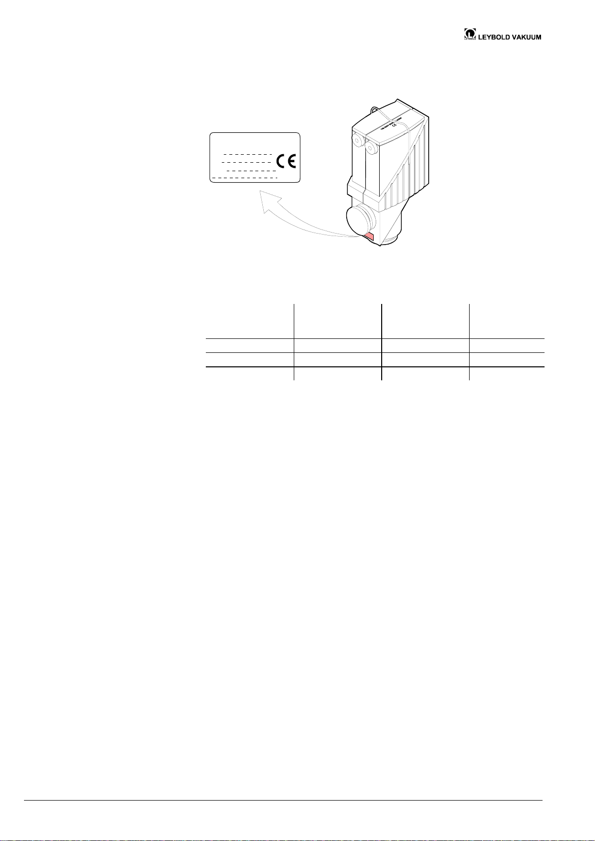
Product identification
In all communications with Leybold Vakuum, please specify the information given
on the product nameplate. For convenient reference copy that information into the
nameplate replica below.
Leybold Vakuum GmbH,
D-50968 Köln
Typ:
No:
F-No:
Validity
Intended Use
Functional Principle
This document applies to products with the following catalog numbers:
Aluminum housing
with FPM seals
Stainless steel
housing with
FPM seals
Stainless steel
housing with
EPDM seals
287 65 288 65 – DN 16 ISO–KF
287 66 288 66 – DN 25 ISO–KF
287 67 288 67 288 68 DN 40 ISO–KF
The catalog number (No) can be taken from the product nameplate.
If not indicated otherwise in the legends, the illustrations in this document correspond to the valve with the nominal diameter DN 25 ISO-KF. They apply to
valves with other nominal diameters by analogy.
We reserve the right to make technical changes without prior notice.
The electromagnetically actuated bellows sealed angle valves are used as shut-off
or venting devices in vacuum applications.
The angle valves are opened electromagnetically and closed by means of a
prestressed pressure spring. They close, or remain closed, on power loss.
Trade Marks
The following trade marks and firms are the property of their respective owners:
Loctite
® Loctite Corporation
Torx
® Camcar/Textron, Inc.
All other trade marks or trade names are the property of their respective owners.
2 GA 06.422/2.02 (0209) DN 16–40 ISO-KF.om
Artisan Technology Group - Quality Instrumentation ... Guaranteed | (888) 88-SOURCE | www.artisantg.com
Page 4

Contents
Product identification 2
Validity 2
Intended Use 2
Functional Principle 2
Trade Marks 2
1 Description 4
1.1 Operating modes 4
1.2 Indication of Positions and Faults 5
1.3 Position Indicator (in REMOTE mode only) 5
2 Safety 6
2.1 Symbols Used 6
2.2 General Safety Instructions 6
2.3 Liability and Warranty 6
3 Technical Data 8
4 Installation 9
4.1 Vacuum Connection 10
4.2 Electrical Connection 11
4.2.1 Removing the Cover 11
4.2.2 Setting the Operating Mode Selection Switch 12
4.2.3 Connecting the Feeder Line 13
4.2.4 Connecting the Control Cable (for REMOTE Mode Only) 14
4.2.5 Mounting the Cover 15
5 Operation 16
5.1 Signaling Behavior 16
5.2 Indication of Positions and Faults 16
6 Deinstallation 18
6.1 Electrical Connection 18
6.2 Vacuum Connection 19
7 Troubleshooting 20
8 Maintenance 21
9 Spare Parts 28
10 Returning the Product 30
11 Disposal 30
Declaration of Contamination 31
GA 06.422/2.02 (0209) DN 16–40 ISO-KF.om 3
Artisan Technology Group - Quality Instrumentation ... Guaranteed | (888) 88-SOURCE | www.artisantg.com
Page 5
1 Description
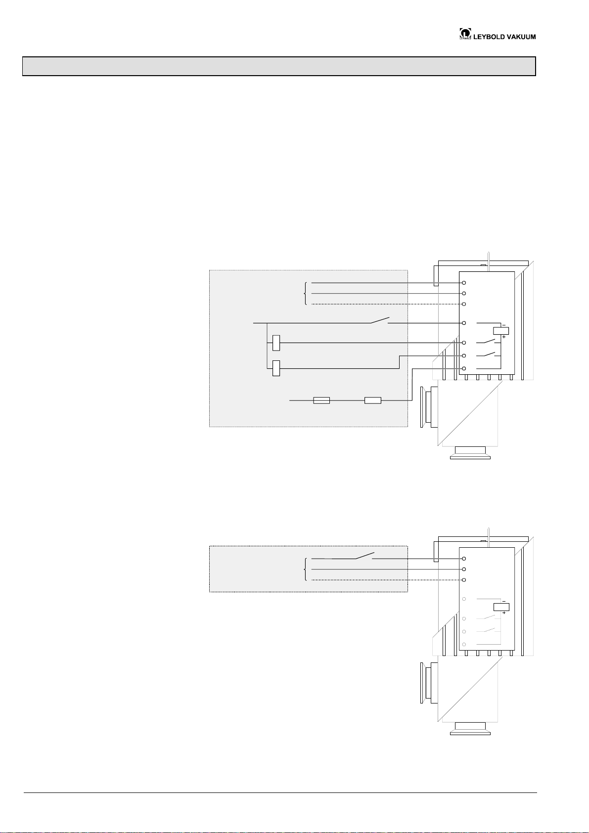
1.1 Operating modes
REMOTE mode
The angle valve has two operating modes:
· REMOTE mode
Drive via control voltage 15 … 30 VDC.
· LOCAL mode
Drive via supply voltage 85 … 248 VAC.
The operating mode is selected by setting a switch (® 2 12).
In the REMOTE mode, the supply voltage of 85 … 248 VAC is constantly fed. The
angle valve is opened and closed via the control contact (0 VDC).
L
85 ... 248 VAC
0 VDC
Control contact
Valve open
Valve closed
N
PE
a
b
c
d
LOCAL mode
W
15 ... 30 VDC
100 mA
Customer's connection
4.7k
Protective resistor
for 30 ... 60 VDC
The angle valve is opened and closed directly via the supply voltage.
L
85 ... 248 VAC
Customer's connection
N
PE
a
b
c
d
4 GA 06.422/2.02 (0209) DN 16–40 ISO-KF.om
Artisan Technology Group - Quality Instrumentation ... Guaranteed | (888) 88-SOURCE | www.artisantg.com
Page 6
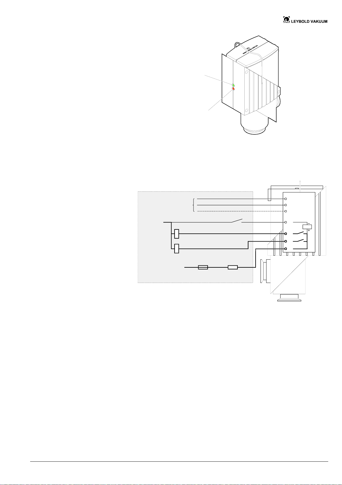
1.2 Indication of Positions
and Faults
1.3 Position Indicator
(in REMOTE mode only)
Green LED lit
Red LED lit
Red LED flashing
= valve open
= valve closed
= fault, for instance
a temperature overload
The integrated position indicator allows for polling the valve positions. In the event
of a fault, the signal "valve closed" is constantly fed.
L
85 ... 248 VAC
0 VDC
Control contact
Valve open
Valve closed
N
PE
a
b
c
d
15 ... 30 VDC
100 mA
Customer's connection
4.7k
Protective resistor
for 30 ... 60 VDC
W
GA 06.422/2.02 (0209) DN 16–40 ISO-KF.om 5
Artisan Technology Group - Quality Instrumentation ... Guaranteed | (888) 88-SOURCE | www.artisantg.com
Page 7
2 Safety
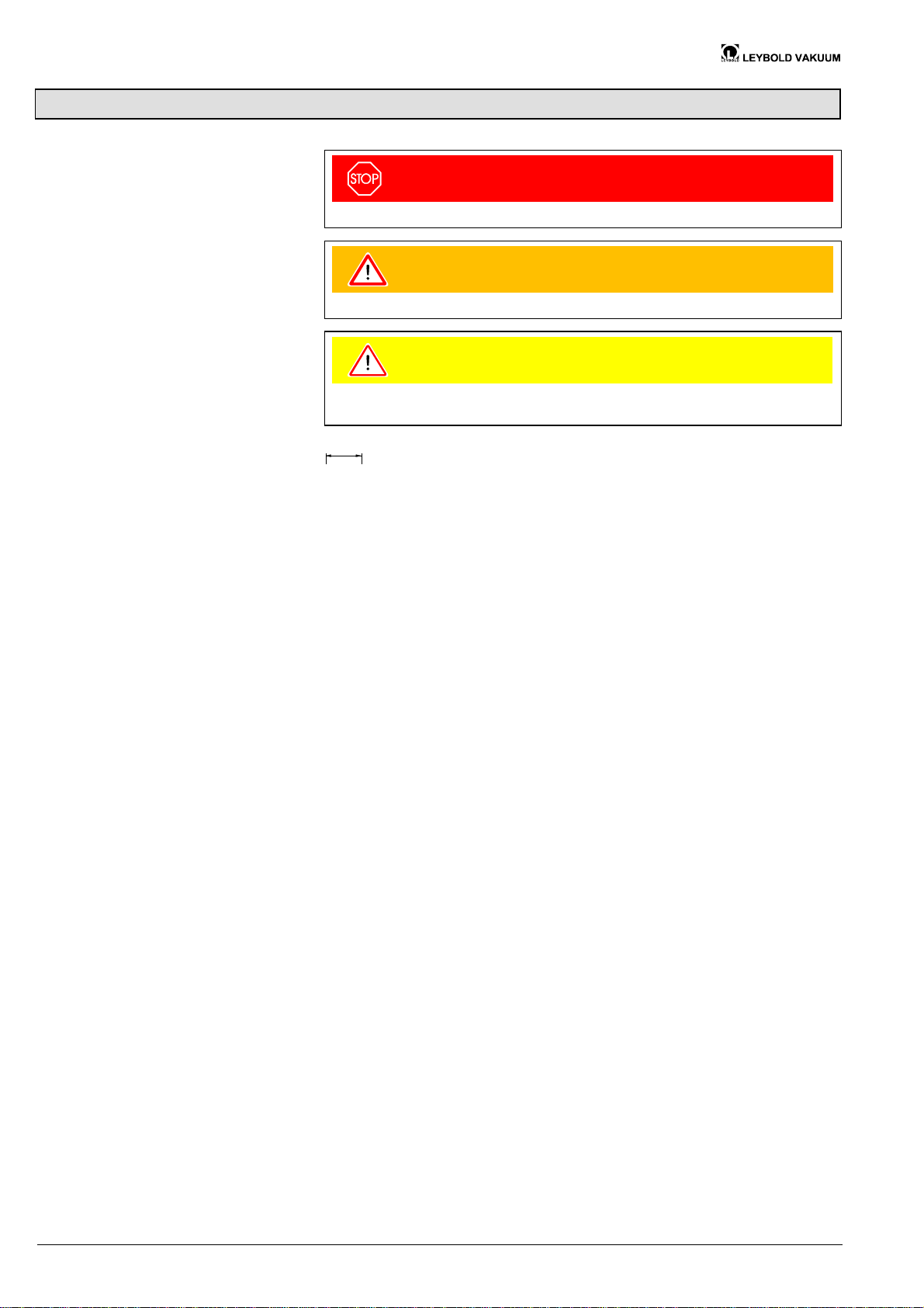
2.1 Symbols Used
DANGER
Information on preventing any kind of physical injury.
WARNING
Information on preventing extensive equipment and environmental damage.
Caution
Information on correct handling or use. Disregard can lead to malfunctions or
minor equipment damage.
20
Dimensions in mm
® 2 See page ...
2.2 General Safety
Instructions
2.3 Liability and Warranty
· Adhere to the applicable regulations and take the necessary precautions for the
process media used.
Consider possible reactions of the process media due to the heat generated by
the product (® 2 9).
· Adhere to the applicable regulations and take the necessary precautions for all
work you are going to do and consider the safety instructions in this document.
· Before beginning to work, find out whether any vacuum components are contaminated. Adhere to the relevant regulations and take the necessary precautions when handling contaminated parts.
Communicate the safety instructions to all other users.
Leybold Vakuum assumes no liability and the warranty becomes null and void if
end-users or third parties
· disregard the information in this document
· use the product in a non-conforming manner
· make any kind of changes (modifications, alterations etc.) to the product
· use the product with accessories and options not listed in the corresponding
product documentation.
The end-user assumes the responsibility in conjunction with the process media
used.
6 GA 06.422/2.02 (0209) DN 16–40 ISO-KF.om
Artisan Technology Group - Quality Instrumentation ... Guaranteed | (888) 88-SOURCE | www.artisantg.com
Page 8

Notes
GA 06.422/2.02 (0209) DN 16–40 ISO-KF.om 7
Artisan Technology Group - Quality Instrumentation ... Guaranteed | (888) 88-SOURCE | www.artisantg.com
Page 9
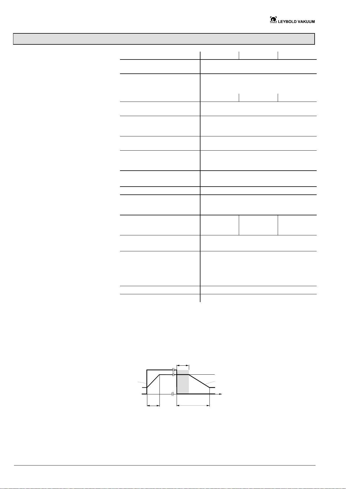
3 Technical Data
Connection flange DN 16 ISO-KF DN 25 ISO-KF DN 40 ISO-KF
Actuation opening: electromagnetically
closing: by pressure spring
Supply voltage
Frequency
Power consumption
400 W (max. upon switching on)
85 … 248 VAC
50 / 60 Hz
Pickup-/Holding power 405/8.1 W 416/8.3 W 367/7.5 W
Control voltage
Power consumption
Position indicator
switching voltage
switching current
Type of protection
Protection class
15 … 30 VDC
3 … 5 mA
2)
3)
15 … 30 VDC
100 mA
IP 54 according to DIN 40 050
1)
II
Cable diameter
feeder line
control cable
Installation angle
Flow direction
Cycle life
Switching frequency
4)
at 40 °C
at 50 °C
5)
5)
Opening time
Closing time
Dead time
6)
Pressure range
Bursting pressure
100 ms
240 ms
50 ms
1×10
5 … 7 mm
5 … 7 mm
any
any
2 million
30 / min
20 / min
120 ms
240 ms
170 ms
-
8
mbar … 1.3 bar (absolute)
3 bar (overpressure)
230 ms
700 ms
500 ms
Pressure difference Dp
in closing direction
in opening direction
1.3 bar
1.3 bar
Opens to a pressure
difference Dp
1.3 bar
Ambient temperature 0 … 50 °C
-
Tightness 1×10
9
mbar l/s
1)
30 … 60 VDC with serial resistor (RV = 4.7 kW, installation ® 2 14)
2)
Corresponds to the control voltage
3)
Must be protected with a quick-acting 100 mA fuse provided by the end-user
4)
Cycles without expendable parts (seals) and under clean operating conditions
5)
Ambient temperature
6)
Dead time
on
Controlsignal
off
Opening time
Closing time
open
Valve position
close
t
8 GA 06.422/2.02 (0209) DN 16–40 ISO-KF.om
Artisan Technology Group - Quality Instrumentation ... Guaranteed | (888) 88-SOURCE | www.artisantg.com
Page 10
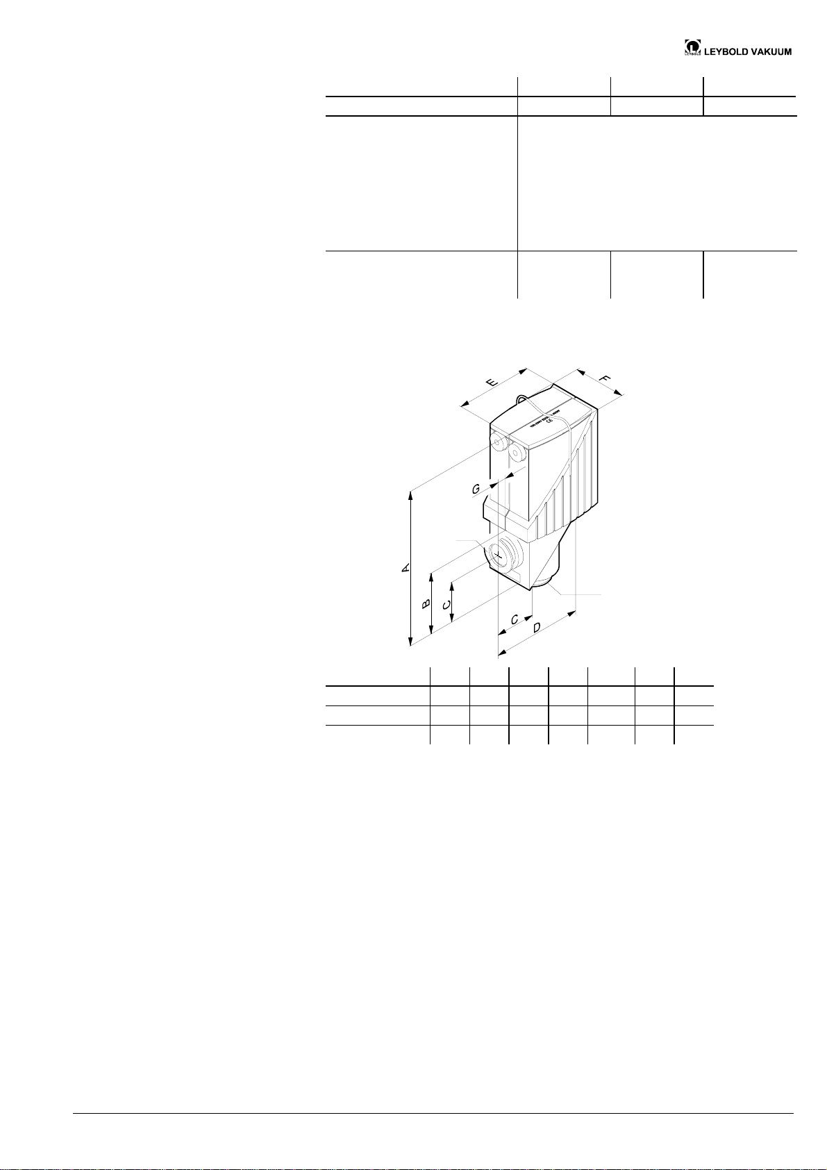
Dimensions in mm
Connection flange DN 16 ISO-KF DN 25 ISO-KF DN 40 ISO-KF
Conductance
7)
4 l/s 16 l/s 40 l/s
Materials
housing
aluminum (3.2374) or
stainless steel (1.4301)
inside section
1.4301 and 1.4541
seals
287 65-67
288 65-67
288 68
shell
FPM
FPM
EPDM
PAGV 30
Weight
aluminum housing
stainless steel housing
7)
For air with molecular flow
1.3 kg
1.5 kg
2.2 kg
2.9 kg
4 kg
5.4 kg
DN
DN
DN A B C D E F G
DN 16 ISO–KF 160 58 40 96 84.5 59 7.5
DN 25 ISO–KF 194 76 50 111 96.5 75 10
DN 40 ISO–KF 230 98 65 138 119.5 96 13.5
GA 06.422/2.02 (0209) DN 16–40 ISO-KF.om 9
Artisan Technology Group - Quality Instrumentation ... Guaranteed | (888) 88-SOURCE | www.artisantg.com
Page 11
4 Installation
4.1 Vacuum Connection
Skilled personnel
The vacuum connection may only be established by persons who have
suitable technical training and the necessary experience or who have
been instructed by the end-user of the product.
DANGER
Caution: overpressure in the vacuum system >1 bar
Injury caused by released parts and harm caused by escaping process
gases can result if clamps are opened while the vacuum system is
pressurized.
Do not open any clamps while the vacuum system is pressurized. Use
the type clamps which are suited to overpressure.
Caution
Caution: vacuum component
Dirt and damages impair the function of the vacuum component.
When handling vacuum components, take appropriate measures to
ensure cleanliness and prevent damages.
Caution
Procedure
Caution: dirt sensitive area
Touching the product or parts thereof with one's bare hands increases
the desorption rate.
Always wear clean, lint-free gloves and use clean tools when working
in this area.
Keep the protective lids.
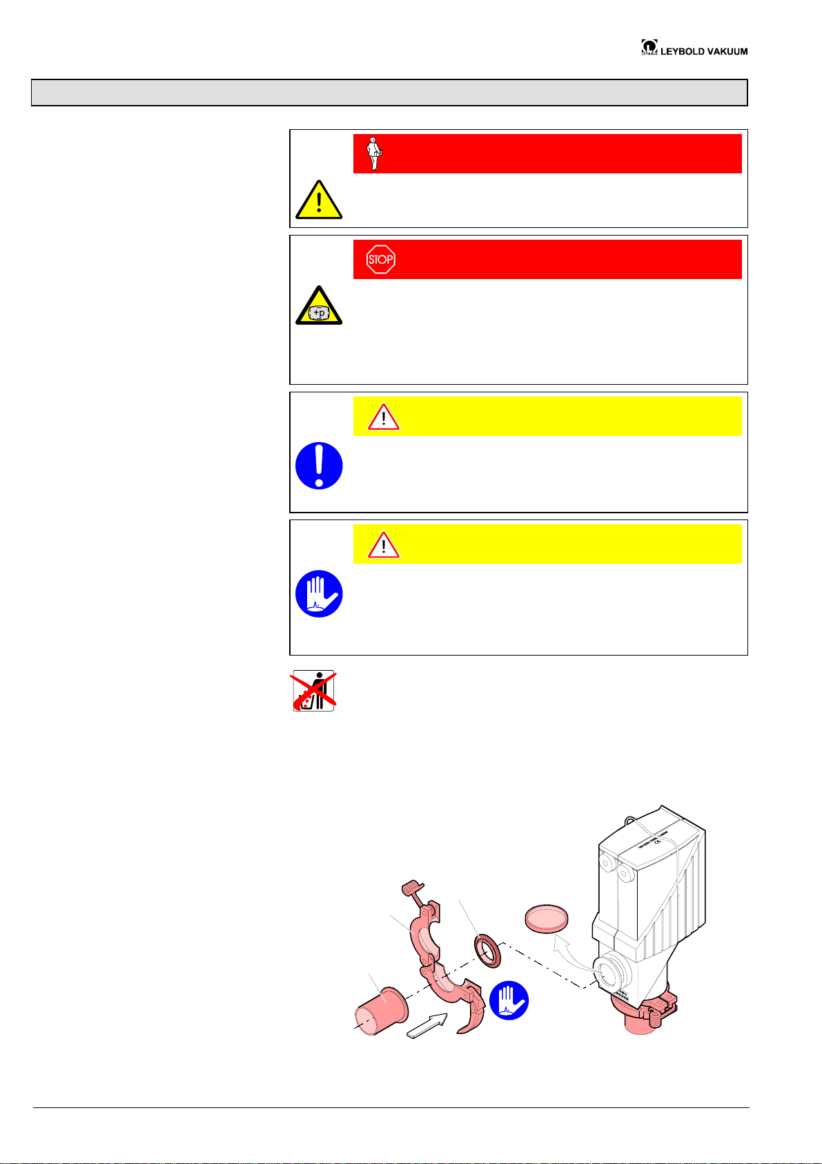
Remove the protective lids and install the valve to the vacuum system by means of
the small flange fittings.
Any installation angle and flow direction may be chosen.
Centering ring
with O-ring
Clamp
ISO-KF
connection
flange
Protective lid
10 GA 06.422/2.02 (0209) DN 16–40 ISO-KF.om
Artisan Technology Group - Quality Instrumentation ... Guaranteed | (888) 88-SOURCE | www.artisantg.com
Page 12
4.2 Electrical Connection
Skilled personnel
The electrical connection, in accordance with the VDE 0100
guidelines, may be made only by a licensed electrician, qualified as per
VDE 0105. The line cables shall be isolated from the line supply during
all electrical work.
DANGER
Caution: mains voltage
Products that are not professionally connected to ground can be
hazardous in the event of a malfunction.
Connect the product according to the local regulations and ground it
correctly.
Caution
Caution: electrostatic fields
If the valve is installed in the vicinity of switched or electronically
controlled heavy electric loads, such as furnaces, heaters, motors or
RF generators, disturbances may occur.
Install a mains filter in the supply line of the valve.
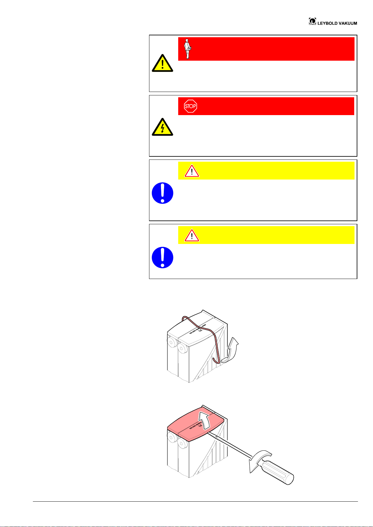
4.2.1 Removing the Cover
Caution
Caution: high voltage tests
The valve is factory tested according to the DIN EN 60 204 standard.
Additional high voltage tests may destroy the valve.
Do not carry out any further high voltage tests.
Remove the clamp.
Remove the cover.
GA 06.422/2.02 (0209) DN 16–40 ISO-KF.om 11
Artisan Technology Group - Quality Instrumentation ... Guaranteed | (888) 88-SOURCE | www.artisantg.com
Page 13
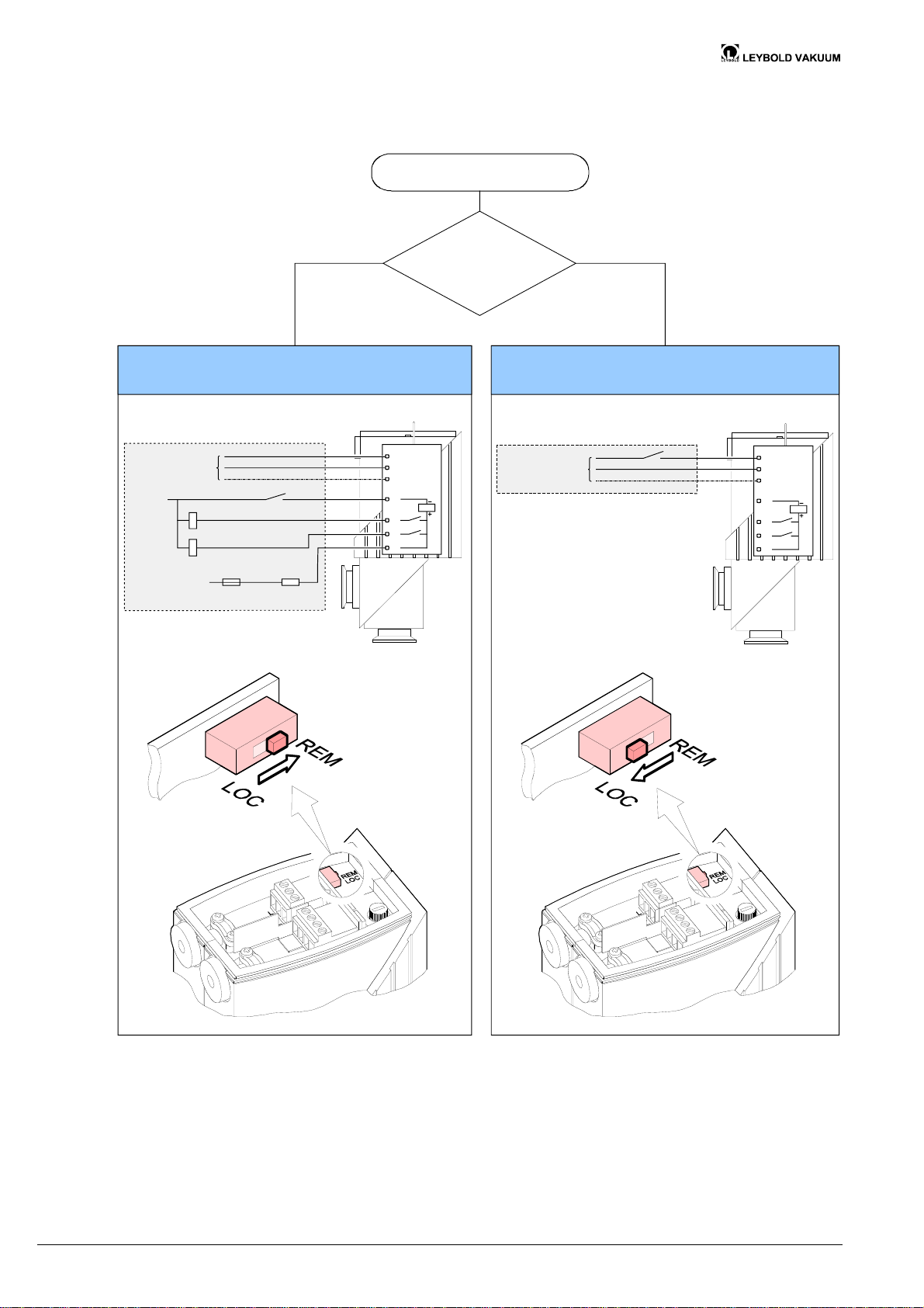
4.2.2 Setting the Operating
Mode Selection Switch
The operating mode must be selected before the electrical connection is established. If a 15 … 30 VDC control voltage is available, choose REMOTE.
Setting the operating mode switch
85 ... 248 VAC
0 VDC
15 ... 30 VDC
Control contact
REMOTE mode
Valve open
Valve closed
W
100 mA
Customers' connection
4.7k
Protective resistor
for 30 ... 60 VDC
Yes No
Control voltage
15 ... 30 VDC
available?
L
N
PE
a
b
c
d
85 ... 248 VAC
Customer's connection
LOCAL mode
L
N
PE
a
b
c
d
12 GA 06.422/2.02 (0209) DN 16–40 ISO-KF.om
Artisan Technology Group - Quality Instrumentation ... Guaranteed | (888) 88-SOURCE | www.artisantg.com
Page 14
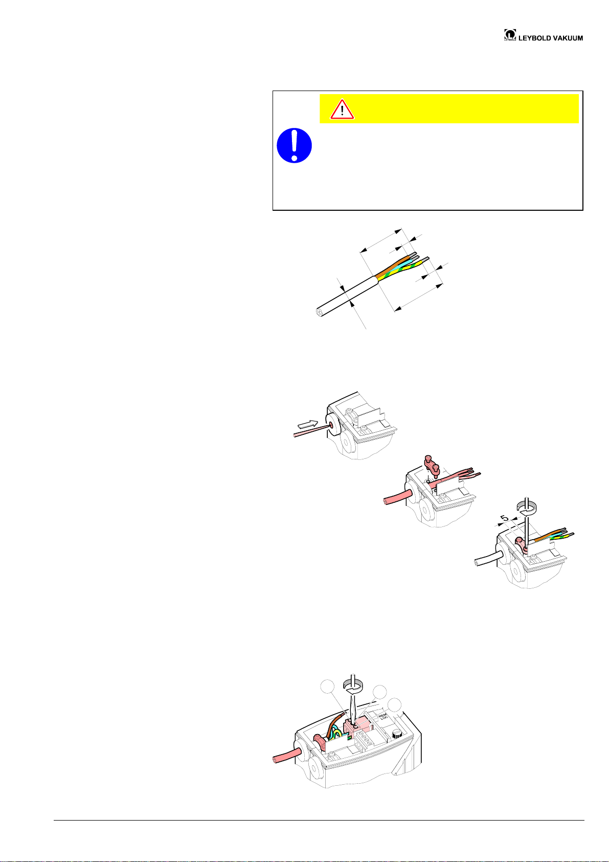
4.2.3 Connecting the Feeder
Line
Prepare the feeder line.
The cable must meet the following specifications:
· flexible
· conductor cross-section 1 mm
· 3-pole with protective conductor (P+N+PE)
· 5 … 7 mm diameter
(for the cable feedthrough to meet the IP 54 specifications)
ø
5
Caution
0
4
.
.
.
7
2
8
8
0
5
Connect the feeder line.
Pierce the cable
feedthrough.
Loosen the strainrelief clamp and
introduce the cable.
Connect the conductors.
Fasten the strainrelief clamp.
L
GA 06.422/2.02 (0209) DN 16–40 ISO-KF.om 13
Artisan Technology Group - Quality Instrumentation ... Guaranteed | (888) 88-SOURCE | www.artisantg.com
N
PE
Page 15
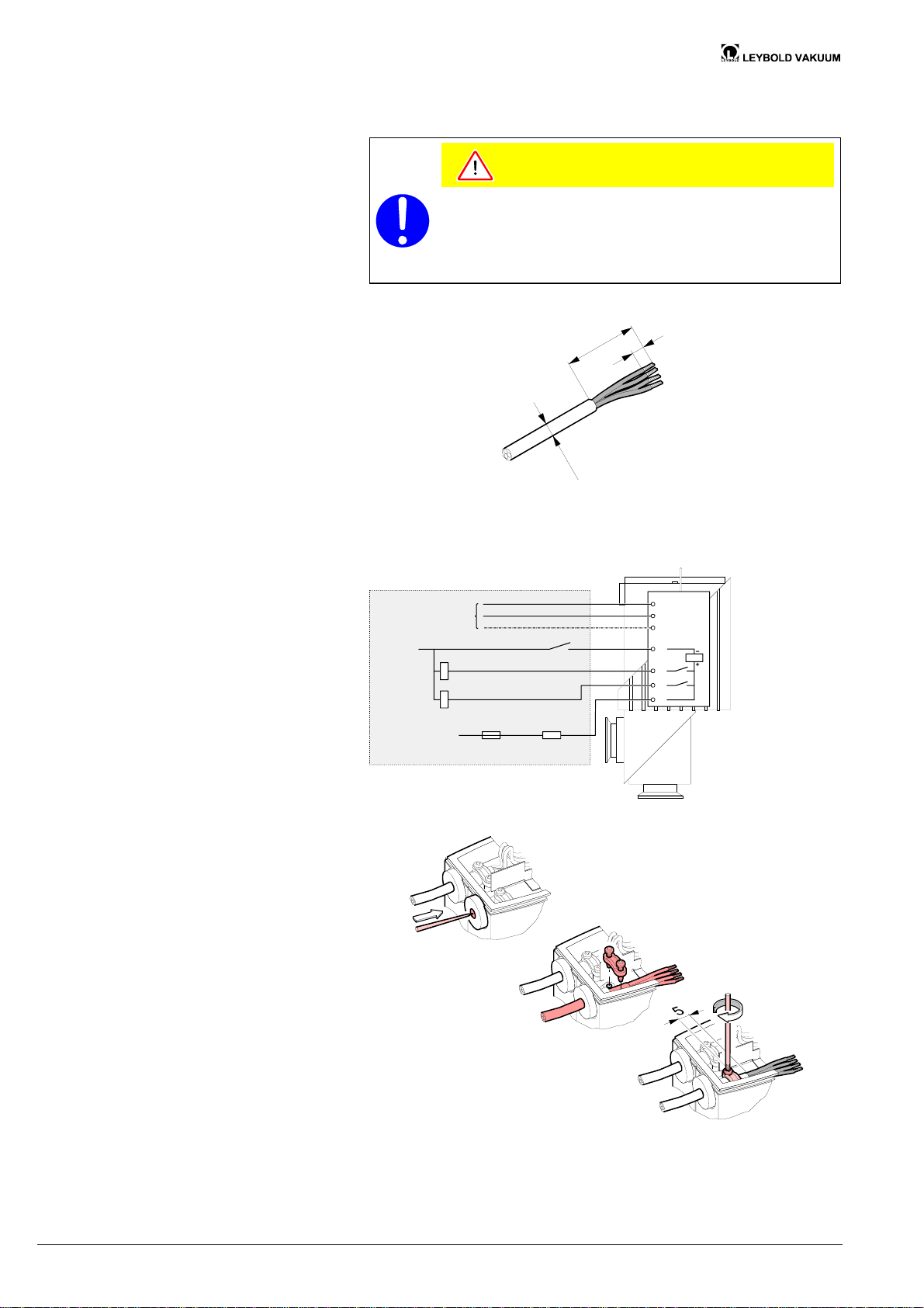
4.2.4 Connecting the Control
Cable (for REMOTE Mode
Only)
Prepare the control cable.
Caution
The cable must meet the following specifications:
· flexible, 4 poles
· conductor cross-section 0.75 mm
· 5 … 7 mm diameter
(for the cable feedthrough to meet the IP 54 specifications)
Connect the control cable.
2
0
4
8
ø
5
.
.
.
7
85 ... 248 VAC
0 VDC
15 ... 30 VDC
Pierce the cable
feedthrough.
Control contact
Valve closed
Valve open
W
100 mA
Customer's connection
Loosen the strainrelief clamp and
introduce the cable.
4,7 k
Protective resistor
for 30 ... 60 VDC
L
N
PE
a
b
c
d
Fasten the strain
relief clamp.
14 GA 06.422/2.02 (0209) DN 16–40 ISO-KF.om
Artisan Technology Group - Quality Instrumentation ... Guaranteed | (888) 88-SOURCE | www.artisantg.com
Page 16
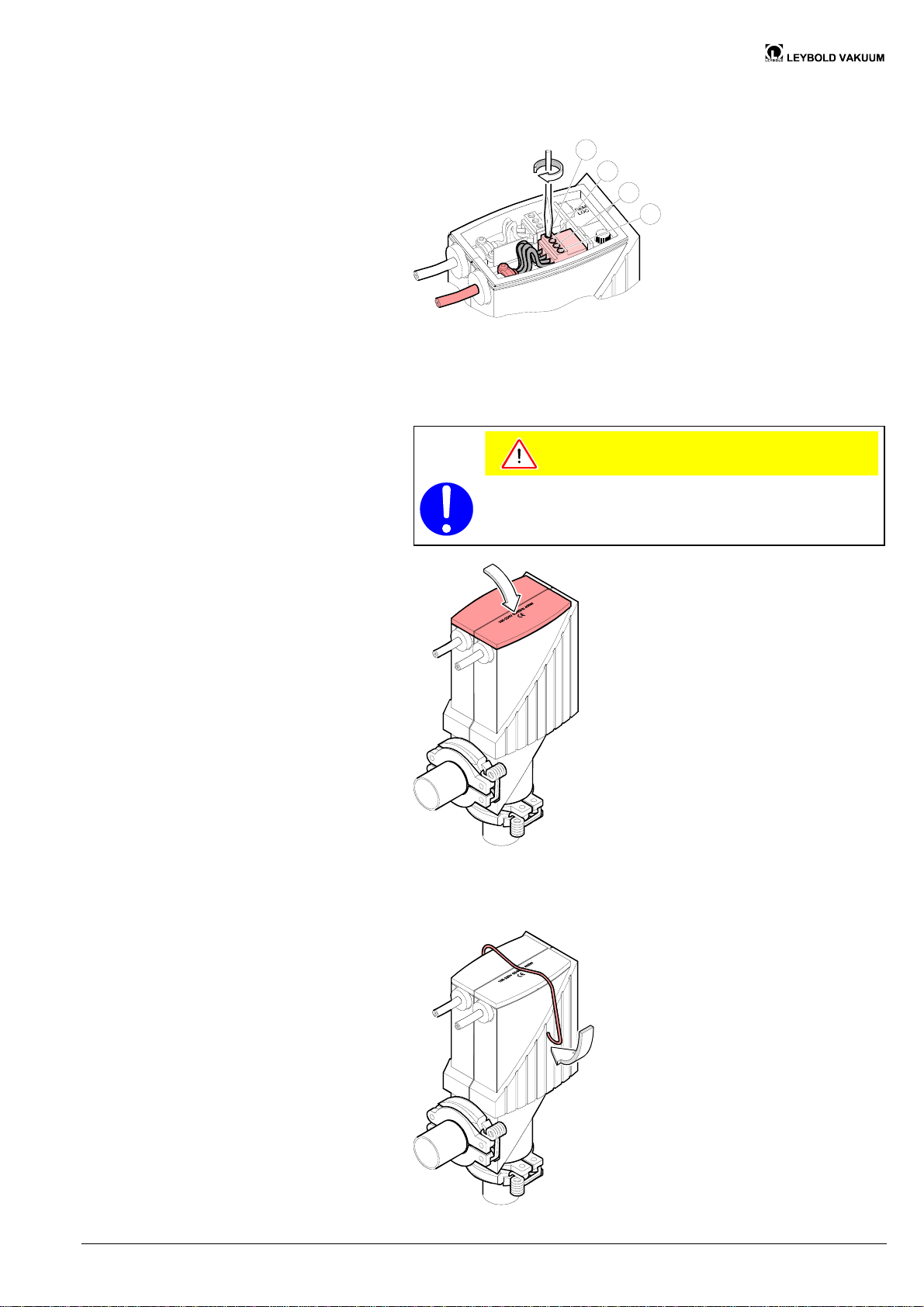
4.2.5 Mounting the Cover
Connect the conductors.
a
b
c
d
Mount the cover.
Caution
Be careful not to squeeze any cable leads.
Mount the clamp again.
GA 06.422/2.02 (0209) DN 16–40 ISO-KF.om 15
Artisan Technology Group - Quality Instrumentation ... Guaranteed | (888) 88-SOURCE | www.artisantg.com
Page 17
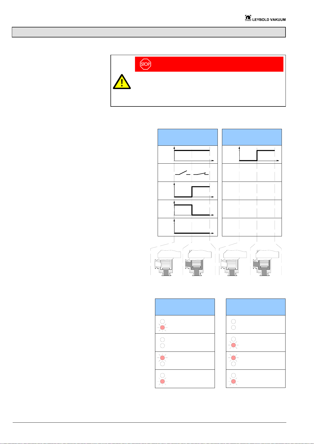
5 Operation
5.1 Signaling Behavior
The product is ready for operation as soon as it has been installed.
DANGER
Caution: bursting pressure
Overpressures >3 bar (e.g. in the event of an explosion) can cause the
inside section and housing to burst. This could result in injuries caused
by catapulted parts and health damages due to leaking process gases.
Protect the entire vacuum system against overpressures >3 bar.
REMOTE mode
LOCAL mode
5.2 Indication of Positions
and Faults
Supply voltage
Control contact
Position indicator
"Valve open"
Position indicator
"Valve closed"
Fault
(same contact as
"Valve closed")
®
248 V
0 V
2
4
24 V
0 V
24 V
0 V
24 V
0 V
REMOTE mode
248 V
0 V
LOCAL mode
Valve closed
Valve opening
Valve open
Fault
red LED lit
both LEDs dark
green LED lit
red LED flashing
both LEDs dark
red LED lights up
briefly
green LED lit
red LED flashing
16 GA 06.422/2.02 (0209) DN 16–40 ISO-KF.om
Artisan Technology Group - Quality Instrumentation ... Guaranteed | (888) 88-SOURCE | www.artisantg.com
Page 18
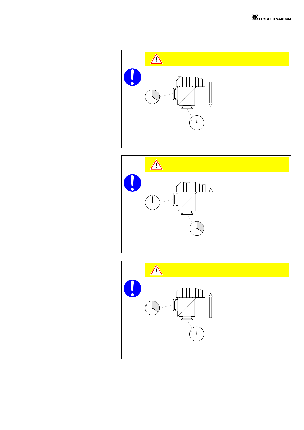
Pressure range
-
8
1×10
mbar … 1.3 bar (absolute)
Pressure difference Dp in closing
direction
Pressure difference Dp in
opening direction
Caution
Caution: pressure difference Dp
p
D
p
bar
p + Dp
p
bar
Closing direction
At Dp >1.3 bar the valve may no longer be tight.
Avoid pressure differences Dp >1.3 bar.
Caution
Caution: pressure difference Dp
p
Opening against a pressure
difference Dp
bar
p +
Opening direction
D
p
bar
p
D
p
At Dp >1.3 bar the valve is opened.
Avoid pressure differences Dp >1.3 bar.
Caution
Caution: pressure difference Dp
p
D
p
bar
p + Dp
p
bar
At Dp >1.3 bar the valve cannot open.
Avoid pressure differences Dp >1.3 bar.
Opening
GA 06.422/2.02 (0209) DN 16–40 ISO-KF.om 17
Artisan Technology Group - Quality Instrumentation ... Guaranteed | (888) 88-SOURCE | www.artisantg.com
Page 19
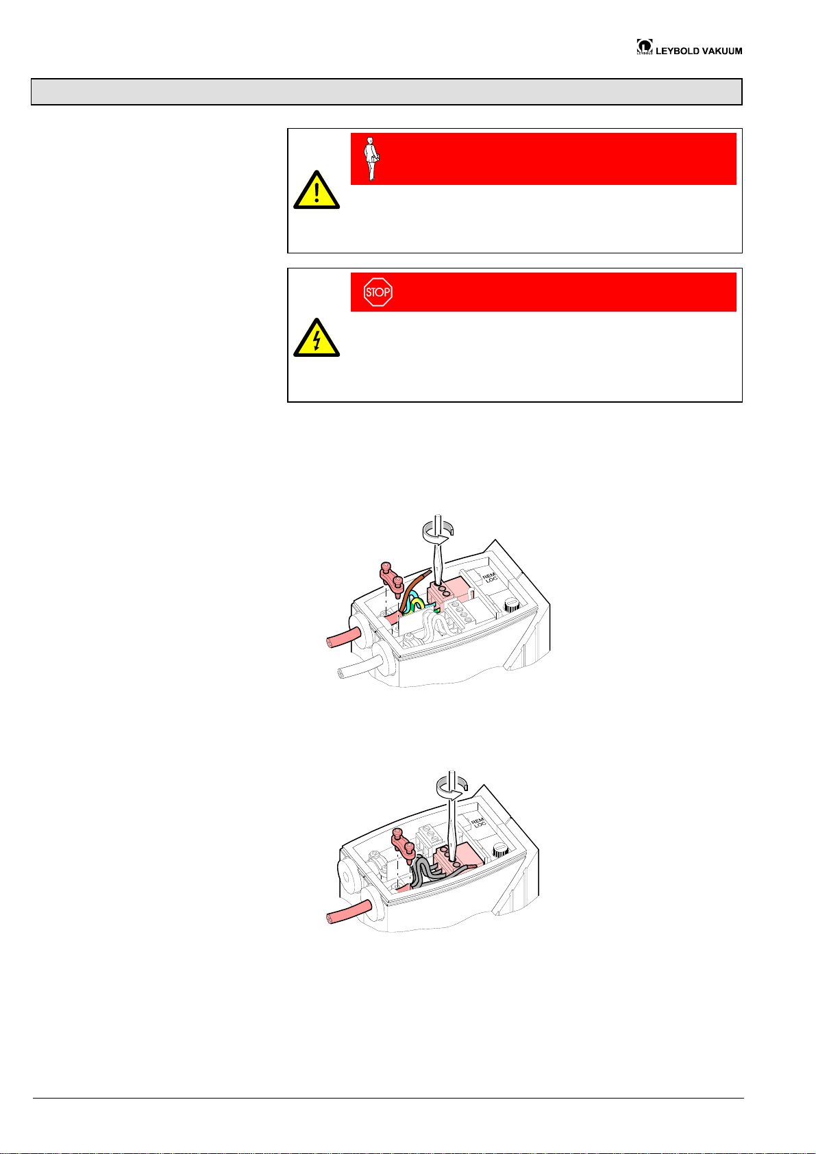
6 Deinstallation
6.1 Electrical Connection
Procedure
Skilled personnel
The electrical connection, in accordance with the VDE 0100
guidelines, may be made only by a licensed electrician, qualified as per
VDE 0105. The line cables shall be isolated from the line supply during
all electrical work.
DANGER
Caution: mains voltage
Touching live parts is hazardous.
Switch all mains and control voltage sources off and secure them
against inadvertent power-on before performing any electrical work on
the product.
Remove the cover (® 2 11).
Disconnect the feeder line.
Disconnect the control cable (for REMOTE mode only).
Mount the cover (® 2 15).
18 GA 06.422/2.02 (0209) DN 16–40 ISO-KF.om
Artisan Technology Group - Quality Instrumentation ... Guaranteed | (888) 88-SOURCE | www.artisantg.com
Page 20
6.2 Vacuum Connection
Skilled personnel
The vacuum connection may only be disassembled by persons who
have suitable technical training and the necessary experience or who
have been instructed by the end-user of the product.
DANGER
Caution: contaminated parts
Contaminated parts can be detrimental to health and environment.
Before beginning to work, find out whether any parts are contaminated.
Adhere to the relevant regulations and take the necessary precautions
when handling contaminated parts.
Caution
Caution: vacuum component
Dirt and damages impair the function of the vacuum component.
When handling vacuum components, take appropriate measures to
ensure cleanliness and prevent damages.
Procedure
Caution
Caution: dirt sensitive area
Touching the product or parts thereof with one's bare hands increases
the desorption rate.
Always wear clean, lint-free gloves and use clean tools when working
in this area.
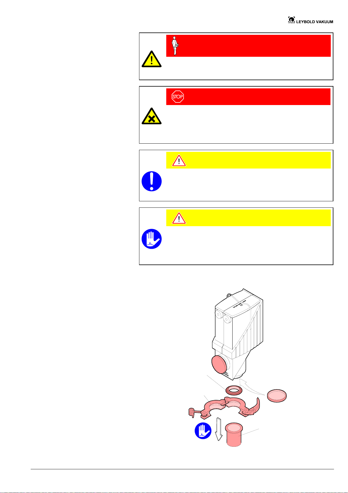
Vent the vacuum system and disassemble the small flange connection. Place the
protective lids.
Centering ring
with O-ring
Clamp
Protective lid
ISO-KF
connection
flange
GA 06.422/2.02 (0209) DN 16–40 ISO-KF.om 19
Artisan Technology Group - Quality Instrumentation ... Guaranteed | (888) 88-SOURCE | www.artisantg.com
Page 21
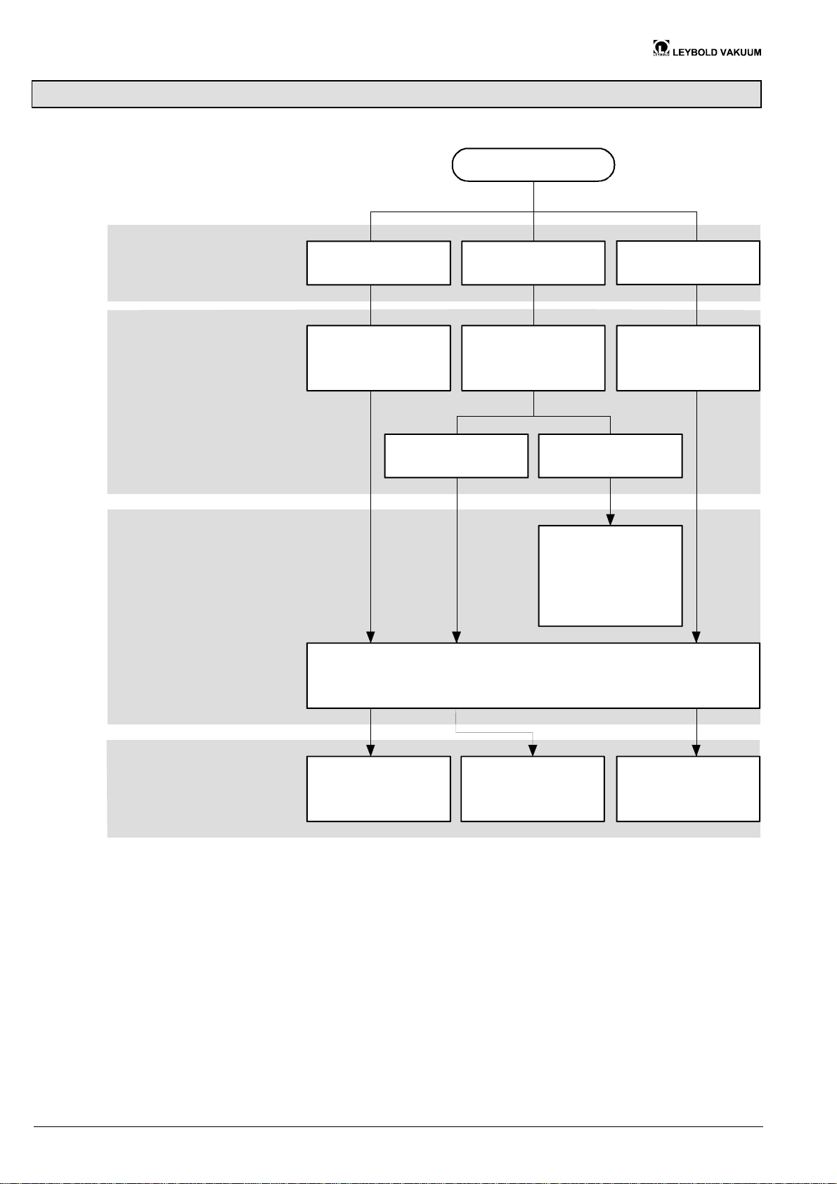
7 Troubleshooting
Troubleshooting
Problem
Cause
Remedy
Valve leaks
Valve seat dirty or
gasket defective
Valve actuator
blocked
Red LED flashing
Temperature
overload
keep ambient tem-
perature < 50° C
or insulate valve
Valve does not
stay open
Position indicator
dirty
Ambient tempe-
rature too high
Cool valve,
Spare parts
®
2
28
Replace inside
section, gaskets
if necessary
Disassemble and clean the valve
(see section Maintenance)
Replace
hoisting magnet
if necessary
Replace
electronics
if necessary
20 GA 06.422/2.02 (0209) DN 16–40 ISO-KF.om
Artisan Technology Group - Quality Instrumentation ... Guaranteed | (888) 88-SOURCE | www.artisantg.com
Page 22
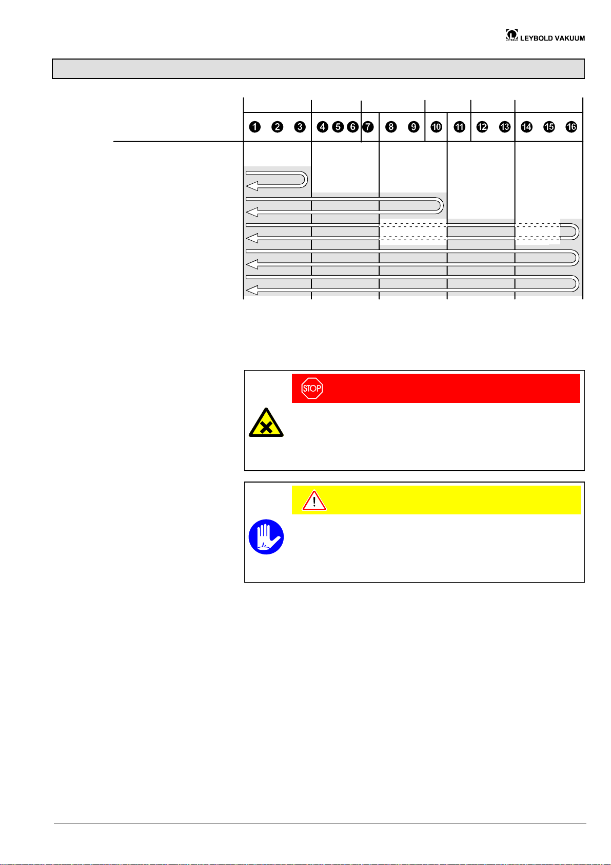
8 Maintenance
Maintenance work:
•
Replacing the fuse and the
fuse holder
•
Replacing the electronics
•
Replacing the gaskets
•
Replacing the hoisting magnet
or the inside section
•
Cleaning the valve
®
2 22
®
2 23
®
2 24
®
2 25
®
2 26
®
2 27
Under clean operating conditions, the product requires no maintenance during the
rated cycle life.
DANGER
Preconditions
Caution: contaminated parts
Contaminated parts can be detrimental to health and environment.
Before beginning to work, find out whether any parts are contaminated.
Adhere to the relevant regulations and take the necessary precautions
when handling contaminated parts.
Caution
Caution: dirt sensitive area
Touching the product or parts thereof with one's bare hands increases
the desorption rate.
Always wear clean, lint-free gloves and use clean tools when working
in this area.
Angle valve removed from the vacuum system (® 2 18).
GA 06.422/2.02 (0209) DN 16–40 ISO-KF.om 21
Artisan Technology Group - Quality Instrumentation ... Guaranteed | (888) 88-SOURCE | www.artisantg.com
Page 23
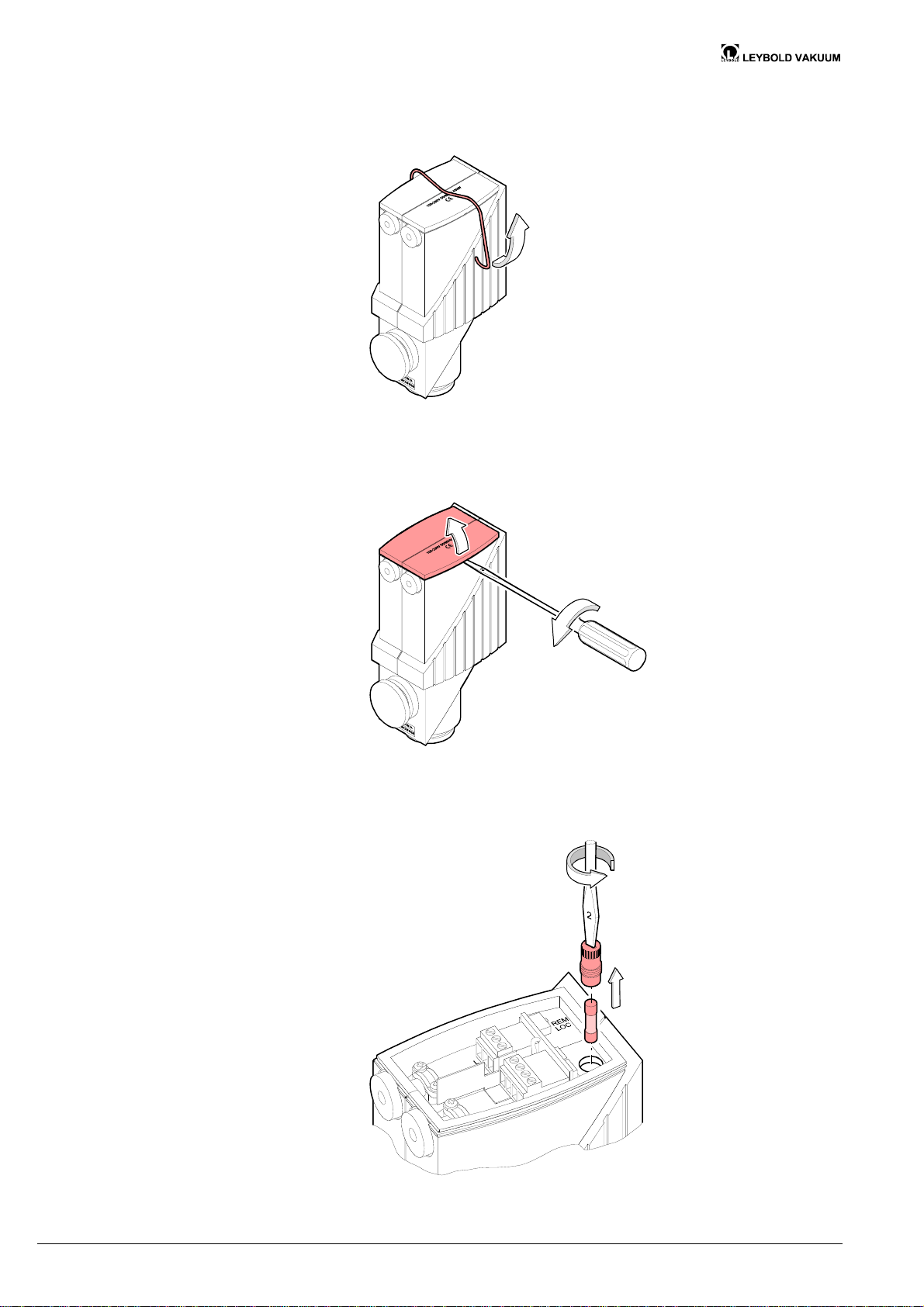
Removing the cover
Remove the clamp.
Remove the cover.
Removing the fuse holder
together with the fuse
Remove the fuse holder together with the fuse.
22 GA 06.422/2.02 (0209) DN 16–40 ISO-KF.om
Artisan Technology Group - Quality Instrumentation ... Guaranteed | (888) 88-SOURCE | www.artisantg.com
Page 24
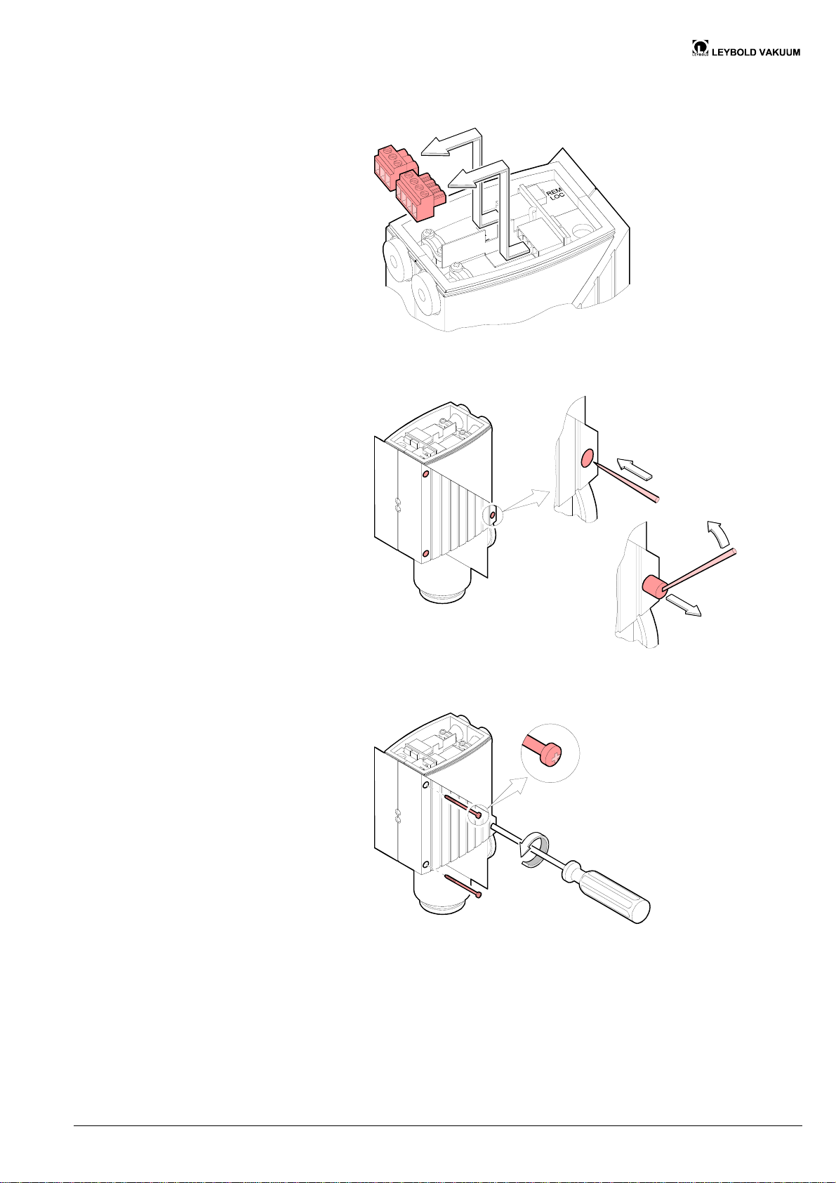
Removing the shell
Remove the connectors.
Pierce the stopper with a pointed tool and pull it out.
Loosen and remove the shell screws.
1
GA 06.422/2.02 (0209) DN 16–40 ISO-KF.om 23
Artisan Technology Group - Quality Instrumentation ... Guaranteed | (888) 88-SOURCE | www.artisantg.com
Page 25
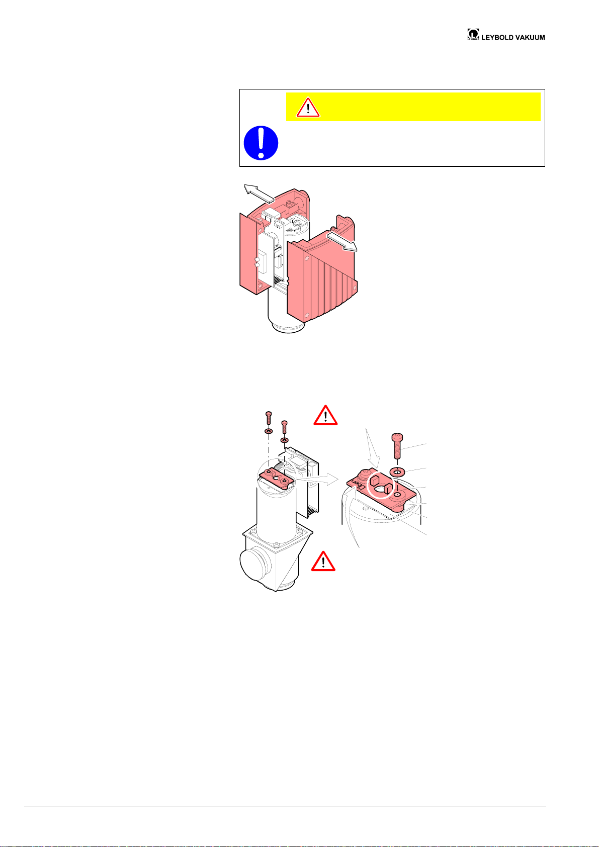
Remove the shell parts.
When reassembling the product: insert the electronics in the
guide notch of the shell parts, be careful not to squeeze any
cables.
Caution
Disassembling the electronics
Unscrew the position indicator.
The photoelectric barrier
must not be dirty.
Cross-recess screw
Washer
Position indicator
Washer
Distance sleeve
Isolating plate
(only for DN 40 ISO-KF)
Be careful to correctly
position the position indicator.
24 GA 06.422/2.02 (0209) DN 16–40 ISO-KF.om
Artisan Technology Group - Quality Instrumentation ... Guaranteed | (888) 88-SOURCE | www.artisantg.com
Page 26
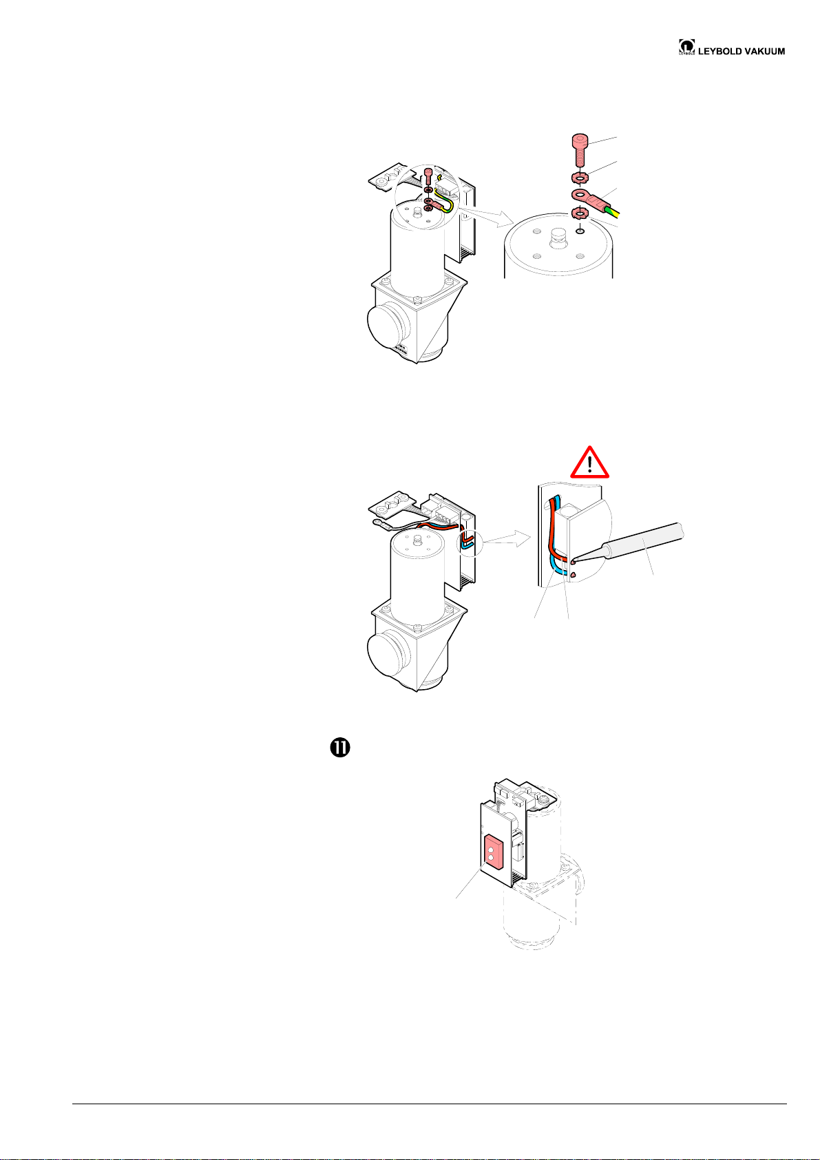
Detach the the protective conductor (PE).
Hexagon socket screw
Serrated lock washer
Cable lug
Serrated lock washer
Unsolder the red and the blue wire of the electronics.
Do not inhale
the vapors.
blue
Check the LED seal and replace it as required.
Cemented LED seal
red
Soldering iron
GA 06.422/2.02 (0209) DN 16–40 ISO-KF.om 25
Artisan Technology Group - Quality Instrumentation ... Guaranteed | (888) 88-SOURCE | www.artisantg.com
Page 27
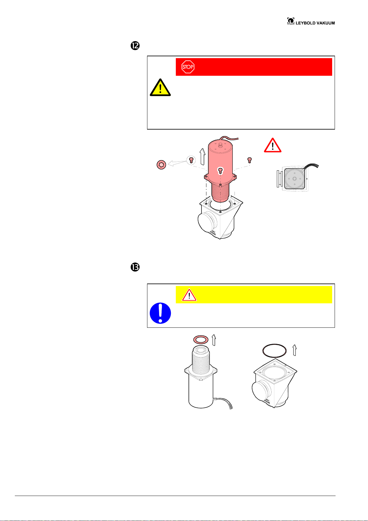
Removing the hoisting magnet
together with the inside section
Remove the hoisting magnet together with the inside section.
DANGER
Caution: prestressed spring
Spring forces: DN 16 =35 N
DN 25 =60 N
DN 40 =105 N
Uncontrolled releasing of the spring can cause injuries.
When loosening the Torx screws, counterhold the hoisting
magnet.
Mount the hoisting
magnet with the
inside section in
this position.
Torx screws
size 3
Removing the seals
Remove the seals from the hoisting magnet with the inside section as well
as from the housing.
Caution
When reassembling the product: be careful to insert the O-rings
level into the grooves without twisting them.
26 GA 06.422/2.02 (0209) DN 16–40 ISO-KF.om
Artisan Technology Group - Quality Instrumentation ... Guaranteed | (888) 88-SOURCE | www.artisantg.com
Page 28
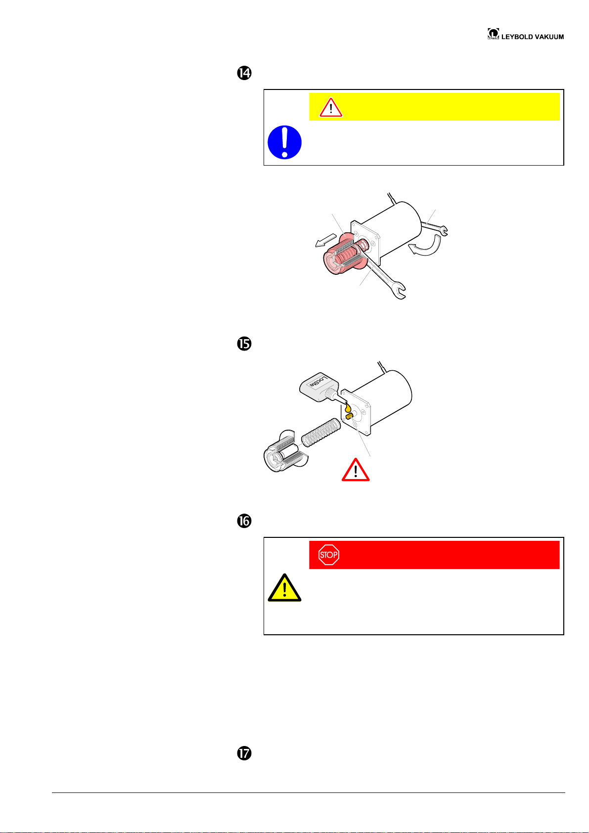
Separate the hoisting magnet
from the inside section
Loosen the inside section.
Caution
Since the inside section is secured with Loctite 241, it is difficult
to loosen it.
Carefully retract
the bellow.
Size 10
Hold stationary.
Remove the inside section and the spring.
Reassembly:
secure with loctite.
Size 6
Clean the parts.
DANGER
Caution: cleaning agents
Cleaning agents can be detrimental to health and environment.
Adhere to the relevant regulations and take the necessary precautions when handling and disposing of cleaning agents. Consider possible reactions with the product materials (® 2 9).
· Carefully clean the parts with a grease solving, non-scouring cleaner.
· After cleaning the parts should preferably be rinsed with alcohol and
subsequently heated to »50° C in an oven or with an industrial blower.
· Carefully clean the sealing surfaces with a lint-free cloth soaked with
alcohol. Allow them to dry.
· Wipe the seals with a lint-free cloth slightly moistened with vacuum oil.
Proceed in reverse order to reassemble the product.
GA 06.422/2.02 (0209) DN 16–40 ISO-KF.om 27
Artisan Technology Group - Quality Instrumentation ... Guaranteed | (888) 88-SOURCE | www.artisantg.com
Page 29
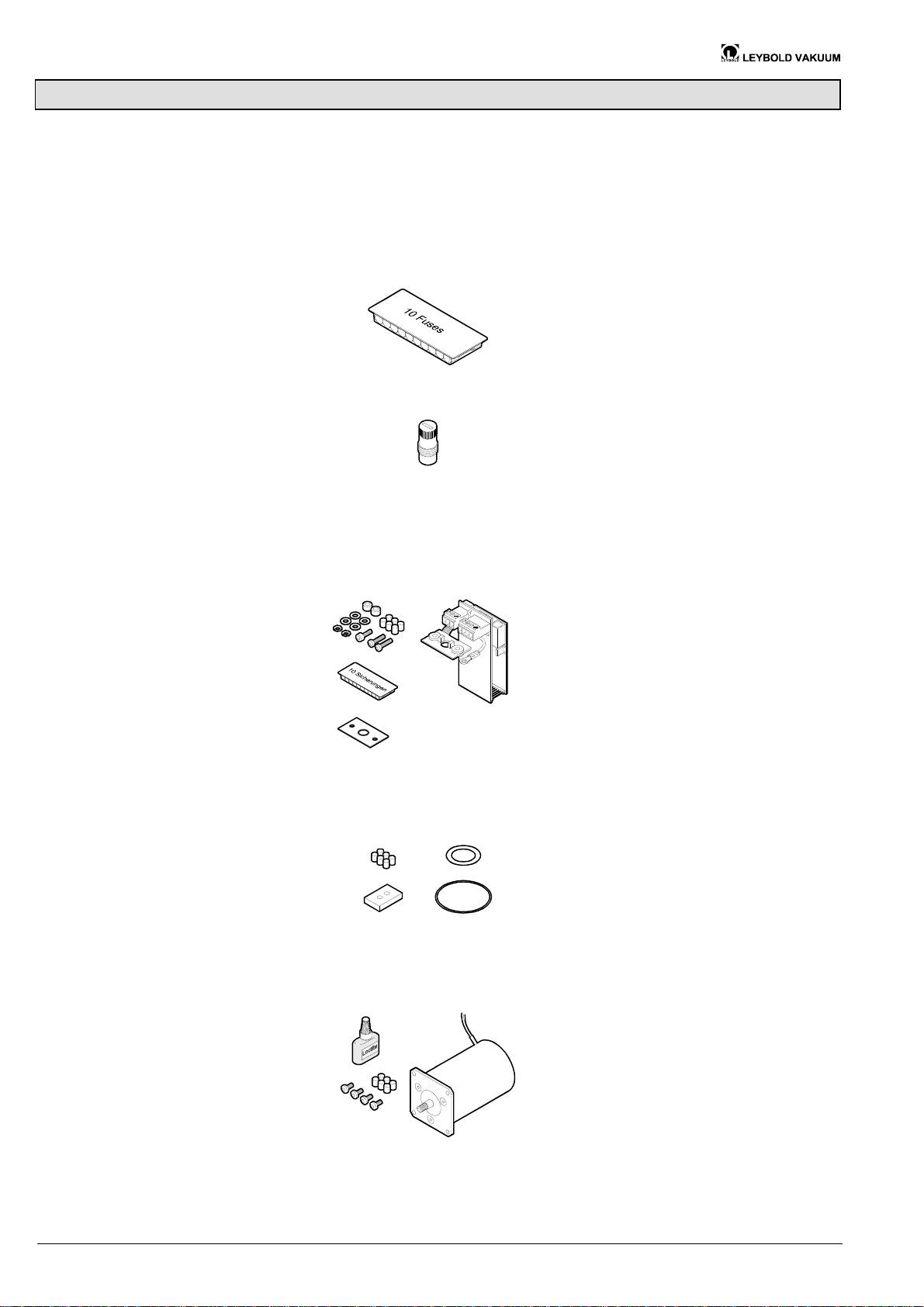
9 Spare Parts
When ordering spare parts, always indicate:
· all information on the product nameplate
· description and ordering number according to the spare parts list
Mounting the spare parts
Fuses
Fuses holder
Electronics
® 2 21.
Ordering numbers
DN 16 ISO-KF: 288 83 (ø5 × 20, 2 A, super slow)
DN 25 ISO-KF: 288 83 (ø5 × 20, 2 A, super slow)
DN 40 ISO-KF: 288 84 (ø5 × 20, 2,5 A, super slow)
Ordering numbers
DN 16 ISO-KF: 288 74
DN 25 ISO-KF: 288 74
DN 40 ISO-KF: 288 74
comprising electronics with position indicator, 10 fuses, distance sleeves, washers,
serrated lock washers, screws, 6 stoppers
Ordering numbers
DN 16 ISO-KF: 288 94
DN 25 ISO-KF: 288 95
DN 40 ISO-KF: 288 96
Gasket kit
Hoisting magnet
Isolating plate
(only for DN 40 ISO-KF)
comprising 2 gaskets, LED seal, 6 stoppers
Ordering numbers
DN 16 ISO-KF: 289 75
DN 25 ISO-KF: 289 76
DN 40 ISO-KF: 289 77
comprising hoisting magnet, screws, Loctite 241, 6 stoppers
Ordering numbers
DN 16 ISO-KF: 288 97
DN 25 ISO-KF: 288 98
DN 40 ISO-KF: 288 99
28 GA 06.422/2.02 (0209) DN 16–40 ISO-KF.om
Artisan Technology Group - Quality Instrumentation ... Guaranteed | (888) 88-SOURCE | www.artisantg.com
Page 30

Bellows assembly
comprising bellows complete, (without spring), Loctite 241, 6 stoppers
Ordering numbers
DN 16 ISO-KF: 288 88
DN 25 ISO-KF: 288 89
DN 40 ISO-KF: 288 90
GA 06.422/2.02 (0209) DN 16–40 ISO-KF.om 29
Artisan Technology Group - Quality Instrumentation ... Guaranteed | (888) 88-SOURCE | www.artisantg.com
Page 31
10 Returning the Product
11 Disposal
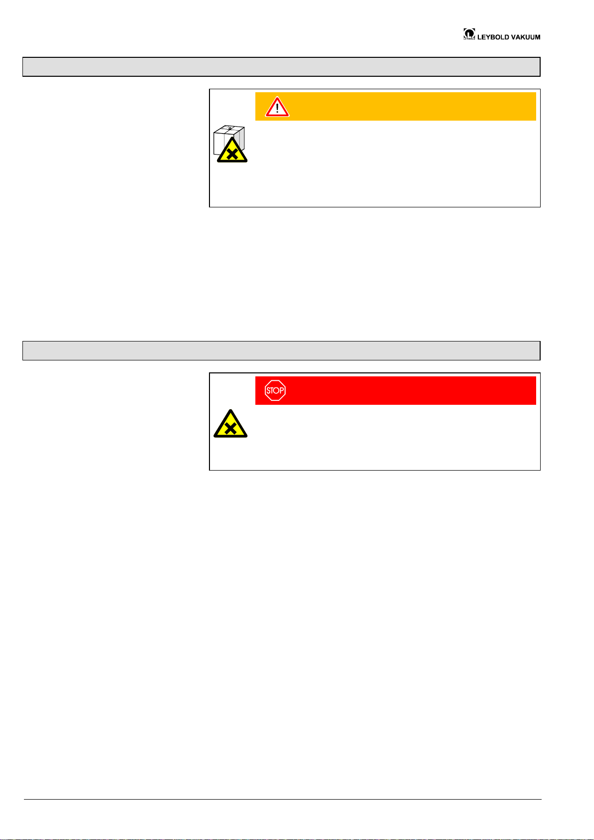
WARNING
Caution: forwarding contaminated products
Contaminated products (e.g. radioactive, toxic, caustic or microbiological hazard) can be detrimental to health and environment.
Products returned to Leybold Vakuum should preferably be free of
harmful substances. Adhere to the forwarding regulations of all
involved countries and forwarding companies and enclose a duly
completed declaration of contamination.
Products that are not clearly declared as "free of harmful substances" are decontaminated at the expense of the customer.
Products not accompanied by a duly completed declaration of contamination are
returned to the sender at his own expense.
Separating the components
Contaminated components
Other components
DANGER
Caution: contaminated parts
Contaminated parts can be detrimental to health and environment.
Before beginning to work, find out whether any parts are contaminated.
Adhere to the relevant regulations and take the necessary precautions
when handling contaminated parts.
After disassembling the product, separate its components according to the
following criteria:
Contaminated components (radioactive, toxic, caustic, or biological hazard etc.)
must be decontaminated in accordance with the relevant national regulations,
separated according to their materials, and disposed of.
Such components must be separated according to their materials and recycled.
30 GA 06.422/2.02 (0209) DN 16–40 ISO-KF.om
Artisan Technology Group - Quality Instrumentation ... Guaranteed | (888) 88-SOURCE | www.artisantg.com
Page 32
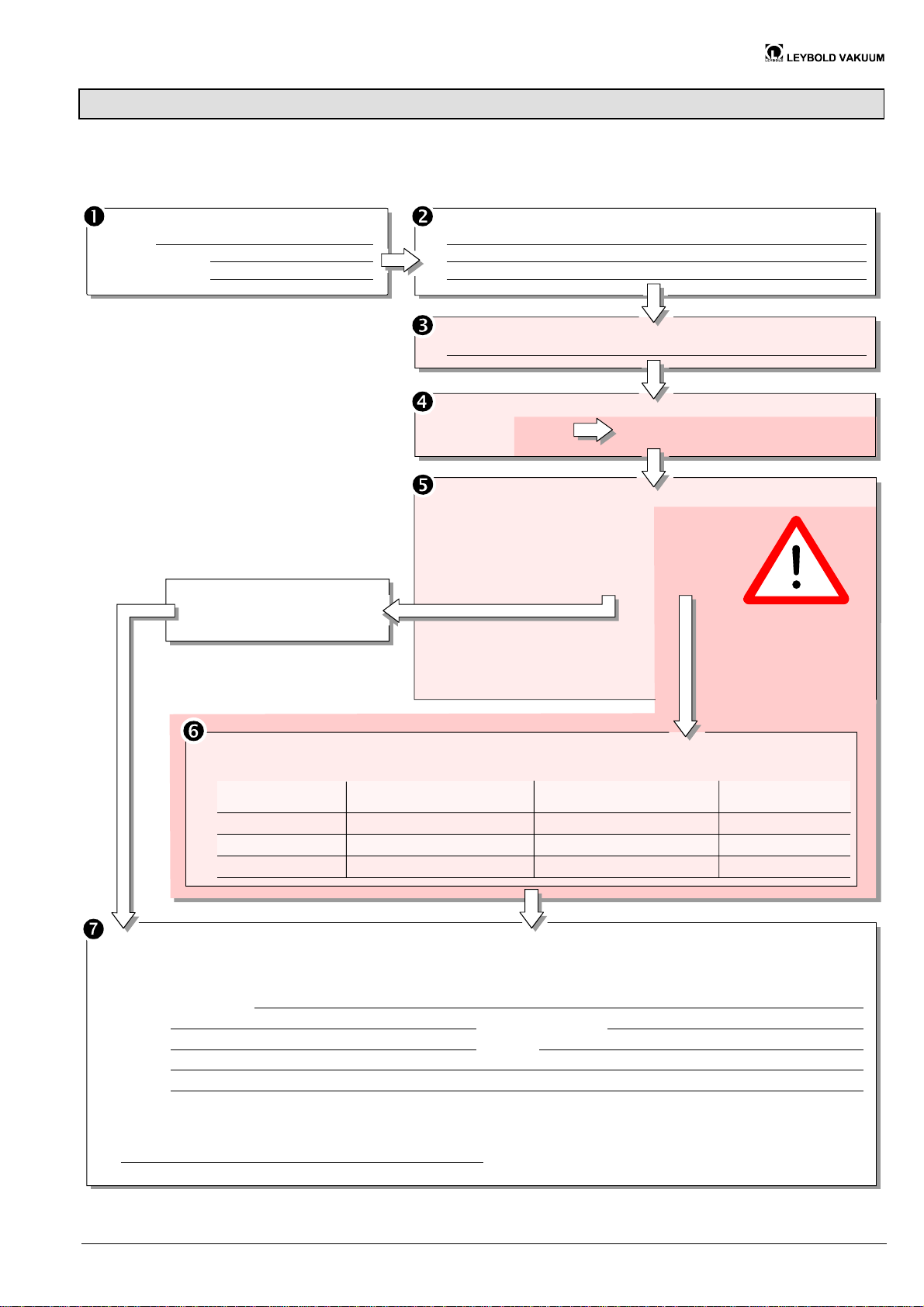
Declaration of Contamination
The service, repair, and/or disposal of vacuum equipment and components will only be carried out if a correctly completed declaration has
been submitted. Non-completion will result in delay.
This declaration may only be completed (in block letters) and signed by authorized and qualified staff.
Description of product
Type
Part number
Serial number
The product is free of any substances which are damaging to
health. yes
Reason for return
Operating fluid(s) used
Used in copper process
no q yes
Process related contamination of product:
toxic no q 1) yes
caustic no q 1) yes q
biological hazard no q yes q 2)
explosive no q yes q 2)
radioactive no q yes q 2)
other harmful substances no q 1) yes
q
1) or not containing any amount
of hazardous residues that
exceed the permissible ex posure limits
q
(Must be drained before shipping.)
Seal product in plastic bag and
mark it with a corresponding label.
q
q
2) Products thus contami nated will not be ac cepted without wri tten
evidence of decontami nation.
Harmful substances, gases and/or by-products
Please list all substances, gases, and by-products which the product may have come into contact with:
Trade/product name
Chemical name
(or symbol)
Precautions associated
with substance
Action if human contact
Legally binding declaration:
We hereby declare that the information on this form is complete and accurate and that we will assume any further costs that may
arise. The contaminated product will be dispatched in accordance with the applicable regulations.
Organization/company
Address Post code, place
Phone Fax
Email
Name
Date and legally binding signature Company stamp
This form can be downloaded
from our we bsite.
Copies:
Original for addresee - 1 copy for accompanying documents - 1 copy for file of sender
GA 06.422/2.02 (0209) DN 16–40 ISO-KF.om 31
Artisan Technology Group - Quality Instrumentation ... Guaranteed | (888) 88-SOURCE | www.artisantg.com
Page 33

Bonner Strasse 498 (Bayenthal)
D–50968 Köln
Deutschland
Tel. +49 (0) 221 347-0
Fax +49 (0) 221 347-1250
Original: German GA 06.422/2.01 (0201) [email protected]
ga06. 422/ 2.02
Artisan Technology Group - Quality Instrumentation ... Guaranteed | (888) 88-SOURCE | www.artisantg.com
www.leyboldvac.de
Page 34

Artisan Technology Group is your source for quality
new and certied-used/pre-owned equipment
• FAST SHIPPING AND
DELIVERY
• TENS OF THOUSANDS OF
IN-STOCK ITEMS
• EQUIPMENT DEMOS
• HUNDREDS OF
MANUFACTURERS
SUPPORTED
• LEASING/MONTHLY
RENTALS
• ITAR CERTIFIED
SECURE ASSET SOLUTIONS
SERVICE CENTER REPAIRS
Experienced engineers and technicians on staff
at our full-service, in-house repair center
Instra
Remotely inspect equipment before purchasing with
our interactive website at www.instraview.com
Contact us: (888) 88-SOURCE | [email protected] | www.artisantg.com
SM
REMOTE INSPECTION
View
WE BUY USED EQUIPMENT
Sell your excess, underutilized, and idle used equipment
We also offer credit for buy-backs and trade-ins
www.artisantg.com/WeBuyEquipment
LOOKING FOR MORE INFORMATION?
Visit us on the web at www.artisantg.com for more
information on price quotations, drivers, technical
specications, manuals, and documentation
 Loading...