

Page 1
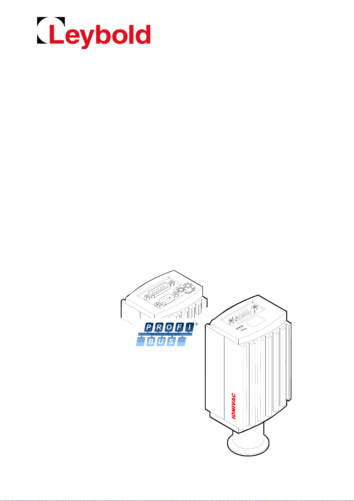
IONIVAC
ITR 90
ITR 90 P
Operating Manual GA09420_002_C0
Part Numbers
120 90
120 91
120 92
120 94
230 030
230 031
Page 2
General Information
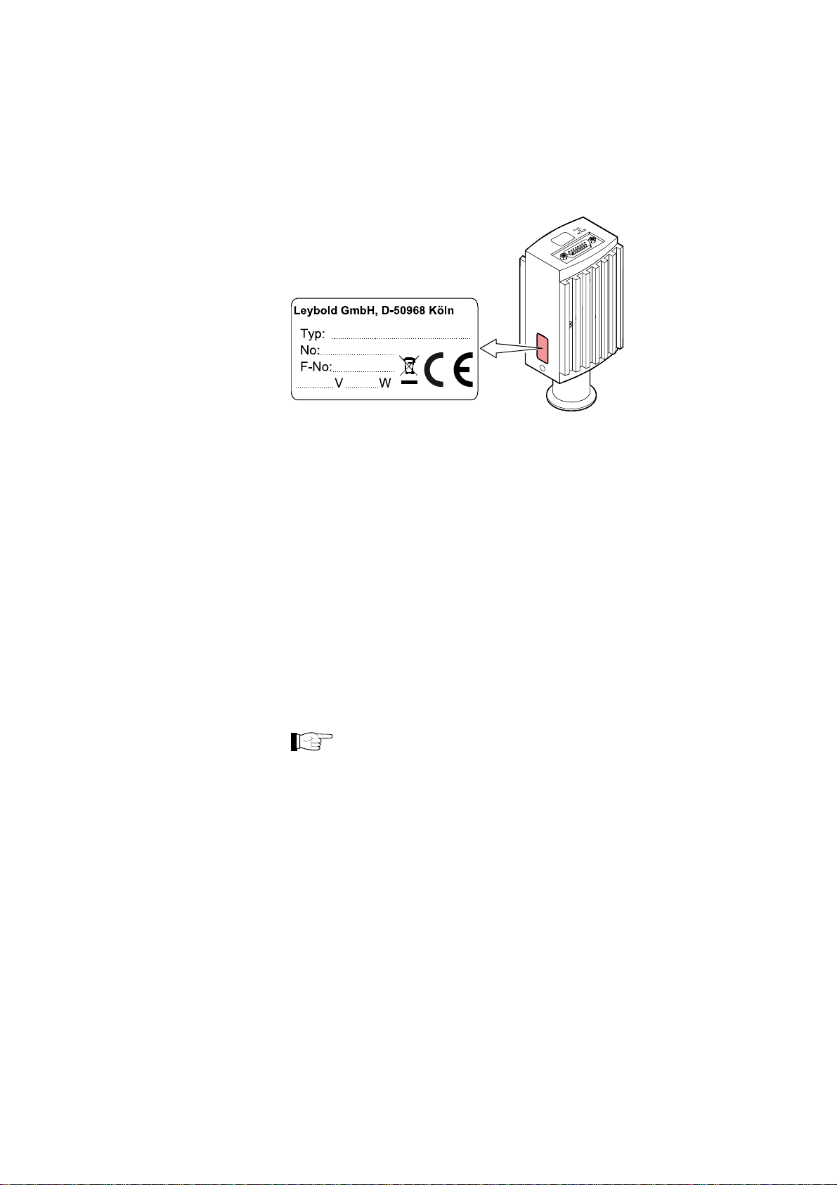
Product Identification
In all communications with Leybold, please specify the information on the product
nameplate. For convenient reference copy that information into the space provided
below.
Validity
This document applies to products with the following part numbers:
ITR 90 (without display)
120 90
(vacuum connection DN 25 ISO-KF)
120 92 (vacuum connection DN 40 CF-R)
ITR 90 (with display)
120 91
120 94
(vacuum connection DN 25 ISO-KF)
(vacuum connection DN 40 CF-R)
ITR 90 P (with Profibus interface and switching functions)
230030 (vacuum connection DN 25 ISO-KF)
230031
(vacuum connection DN 40 CF-R)
The part number (No.) can be taken from the product nameplate.
If not indicated otherwise in the legends, the illustrations in this docu-
ment correspond to the KF vacuum connection. They apply to other
vacuum connections by analogy.
All ITR 90 versions are shipped with an instruction sheet (→ [1]). ITR 90 P
comes with a supplementary instruction sheet describing the fieldbus interfaces
and the switching functions (→ [2]).
We reserve the right to make technical changes without prior notice.
All dimensions in mm.
Intended Use
GA09420_002_C0 – (2016-10) –
2
The ITR 90 transmitters have been designed for vacuum measurement of gases
and gas mixtures in a pressure range of 5×10
-10
… 1000 mbar.
They must not be used for measuring flammable or combustible gases in mixtures
containing oxidants (e.g. atmospheric oxygen) within the explosion range.
The transmitters can be operated in connection with a Leybold controller or with
other control devices.
Leybold
Page 3

General Information
Functional Principle
Over the whole measuring range, the transmitters has a continuous characteristic
curve and its measuring signal is output as logarithm of the pressure.
The transmitters functions with a Bayard-Alpert hot cathode ionization measurement system (p < 2.0×10
(p > 5.5×10
2.0×10
-3
mbar). In the overlapping pressure range of
-2
… 5.5×10⁻³ mbar, a mixed signal of the two measurement systems is
output. The hot cathode is switched on by the Pirani measurement system only
below the switching threshold of 2.4×10⁻² mbar (to prevent filament burn-out). It is
switched off when the pressure exceeds 3.2×10
-2
mbar) and a Pirani measurement system
-2
mbar.
GA09420_002_C0 – (2016-10) –
Leybold
3
Page 4

Contents
Contents
Product Identification 2
Validity 2
Intended Use 2
Functional Principle 3
1 Safety 5
1.1 Symbols Used 5
1.2 Personnel Qualifications 5
1.3 General Safety Instructions 6
1.4 Liability and Warranty 6
2 Technical Data 7
3 Installation 12
3.1 Vacuum Connection 12
3.1.1 Making the Flange Connection 13
3.1.2 Removing and Installing the Electronics Unit 14
3.1.3 Using the Optional Baffle 15
3.2 Electrical Connection 17
3.2.1 Use With Leybold Transmitter Controllers 17
3.2.2 Use With Other Controllers 18
3.2.3 Using the Optional Power Supply (With RS232C Line) 23
4 Operation 25
4.1 Measuring Principle, Measuring Behavior 25
4.2 Operational Principle of the Transmitter 27
4.3 Putting the Transmitter Into Operation 27
4.4 Degas 27
4.5 Display 28
4.6 RS232C Interface 29
4.6.1 Description of the Functions 29
4.7 Profibus Interface (ITR 90 P) 32
4.7.1 Description of the Functions 32
4.7.2 Operating Parameters 33
4.8 Switching Functions (ITR 90 P) 34
4.8.1 Setting the Switching Functions 34
5 Deinstallation 36
6 Maintenance, Repair 37
6.1 Maintenance 37
6.1.1 Cleaning the Transmitter 37
6.2 Adjusting the Transmitter 37
6.2.1 Adjustment at Atmospheric Pressure 37
6.2.2 Zero Point Adjustment 39
6.3 What to Do in Case of Problems 39
6.4 Replacing the Sensor 41
7 Options 43
8 Spare Parts 43
9 Storage 43
10 Returning the Product 44
11 Disposal 44
Appendix 45
A: Relationship Output Signal – Pressure 45
B: Gas Type Dependence 46
C: Literature 48
Declaration of Contamination 49
For cross-references within this document, the symbol (→ XY) is used, for cross-
references to further documents, listed under literature, the symbol (→ [Z]).
GA09420_002_C0 – (2016-10) –
4
Leybold
Page 5
1 Safety
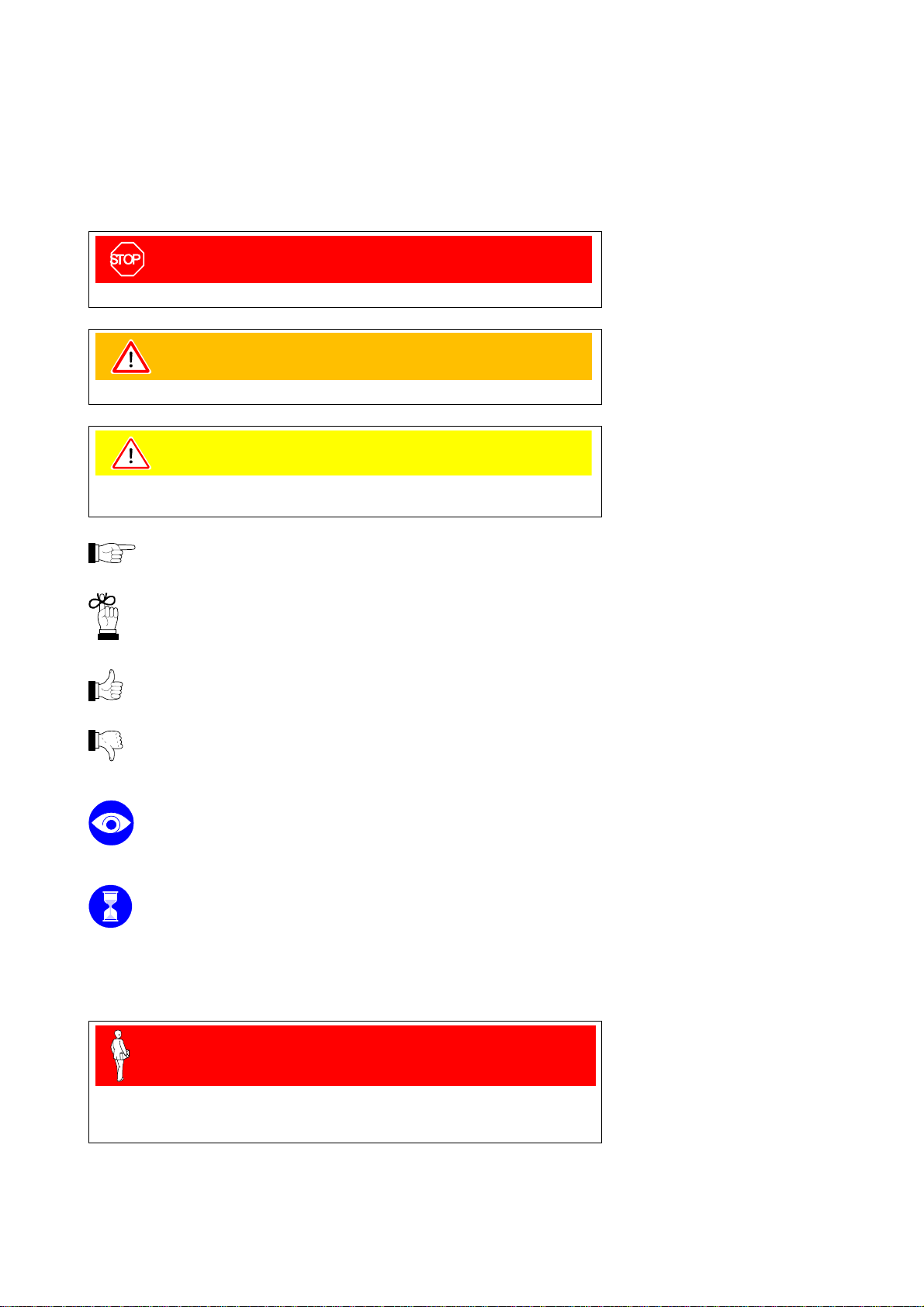
1.1 Symbols Used
DANGER
Information on preventing any kind of physical injury.
WARNING
Information on preventing extensive equipment and environmental damage.
Caution
Information on correct handling or use. Disregard can lead to malfunctions or minor equipment damage.
Safety
Notice
Hint, recommendation
The result is O.K.
The result is not as expected
Optical inspection
Waiting time, reaction time
1.2 Personnel Qualifications
Skilled personnel
All work described in this document may only be carried out by persons who
have suitable technical training and the necessary experience or who have been
instructed by the end-user of the product.
GA09420_002_C0 – (2016-10) –
Leybold
5
Page 6

Safety
1.3 General Safety Instructions
• Adhere to the applicable regulations and take the necessary precautions for the
process media used.
Consider possible reactions between the materials (→ 10) and the process
media.
Consider possible reactions (e.g. explosion) of the process media due to the
heat generated by the product.
• Adhere to the applicable regulations and take the necessary precautions for all
work you are going to do and consider the safety instructions in this document.
• Before beginning to work, find out whether any vacuum components are contaminated. Adhere to the relevant regulations and take the necessary precautions when handling contaminated parts.
Communicate the safety instructions to all other users.
1.4 Liability and Warranty
Leybold assumes no liability and the warranty becomes null and void if the enduser or third parties
• disregard the information in this document
• use the product in a non-conforming manner
• make any kind of interventions (modifications, alterations etc.) on the product
• use the product with accessories not listed in the corresponding product docu-
mentation.
The end-user assumes the responsibility in conjunction with the process media
used.
Transmitter failures due to contamination or wear and tear as well as
expendable parts (filaments) are not covered by the warranty.
GA09420_002_C0 – (2016-10) –
6
Leybold
Page 7

2 Technical Data
Measurement
Display range (air, O
, CO, N2,) 5×10
2
-10
… 1000 mbar, continuous
Measuring range (air, O2, CO, N2,) 1×10⁻⁸ … 10-2 mbar, continuous
Accuracy 15% of reading
(after 5 min stabilization)
Repeatability 5% of reading
(after 5 min stabilization)
Gas type dependence
→ Appendix B
Emission
Technical Data
Switching on threshold
Switching off threshold
Emission current
p ≤7.2×10
7.2×10
-6
mbar
-6
mbar <p <3.2×10⁻² mbar
Emission current switching
25 µA 5 mA
5 mA 25 µA
2.4×10⁻² mbar
-2
3.2×10
mbar
5 mA
25 µA
-6
7.2×10
3.2×10
mbar
-5
mbar
Degas
Degas emission current
(p <7.2×10
-6
mbar)
≈16 mA (P
degas
≈4 W)
Control input signal 0 V/+24 VDC, active high
(control via RS232 → 29)
Duration max. 3 min, followed by automatic stop
In degas mode, ITR 90 transmitters keep supplying measurement values, however
their tolerances may be higher than during normal operation.
Output signal
Output signal (measuring signal) 0 … +10 V
Display range 0.774 V … +10 V
(5×10
-10
mbar … 1000 mbar)
Relationship voltage-pressure logarithmic, 0.75 V/decade
(
→ Appendix A)
Error signal
Minimum load impedance
<0.3 V/0.5 V (→ 39)
10 kΩ
Display (120 91 and 120 94)
Display panel
Dimensions
Pressure units (pressure p)
LCD matrix, 32×16 pixels,
with background illumination
16.0 mm × 11.2 mm
mbar (default), Torr, Pa
(selecting the pressure unit → 29)
GA09420_002_C0 – (2016-10) –
Leybold
7
Page 8
Technical Data
pp
Power supply
Operating voltage at the
IONIVAC ITR 90
Power consumption
Standard
Degas
Emission start (<200 ms)
Power consumption
ITR 90
ITR 90 P
Fuse necessary 1.25 AT
Sensor cable
DANGER
The transmitter must only be connected to power supplies, instruments or control devices that conform to the requirements of a
grounded extra-low voltage (PELV). The connection to the transmitter
has to be fused (Leybold controllers fulfill these requirements).
+24 VDC (20 … 28 VDC) 1)
ripple max. 2 V
≤0.5 A
≤0.8 A
≤1.4 A
≤16 W
≤18 W
For reasons of compatibility, the expression "sensor cable" is used for all
ITR 90 versions in this document, although the pressure reading of the
transmitters with fieldbus interface (ITR 90 P) is normally transmitted via
the corresponding bus.
Electrical connector
ITR 90
ITR 90 P
Cable for ITR 90
Analog values only
Without degas function
Analog values
With degas function
Analog values
With degas function
And RS232C interface
Cable for ITR 90 P
Max. cable length (supply voltage 24 V
Analog operation
RS232C operation
Transmitter identification
D-Sub,15-pin, male (→ 19)
D-Sub,15-pin, male (→ 20)
4 conductors plus shielding
5 conductors plus shielding
7 conductors plus shielding
depending on the functions used,
max. 15 conductors plus shielding
1)
)
≤35 m, conductor cross-section 0.25 mm²
≤50 m, conductor cross-section 0.34 mm²
≤100 m, conductor cross-section 1.0 mm²
≤30 m
42 kΩ resistor between Pin 10 (sensor
cable) and GND
1)
Measured at sensor cable connector (consider the voltage drop as function of
the sensor cable length).
GA09420_002_C0 – (2016-10) –
8
Leybold
Page 9

Switching functions
ITR 90
ITR 90 P
Adjustment range
Relay contact rating
Voltage
Current
RS232C interface
Technical Data
none
2 (setpoints A and B)
-9
mbar … 100 mbar
1×10
Setpoints adjustable via potentiometers
(setpoints A and B), one floating, normally open relay contact per setpoint
(→ 20, 34)
Adjusting the setpoints via field bus is
described in the corresponding bus sections.
≤30 V
≤0.5 ADC
Data rate
Data format
Connections (sensor cable connector)
TxD (Transmit Data)
RxD (Receive Data)
GND
9600 Baud
binary
8 data bits
one stop bit
no parity bit
no handshake
Pin 13
Pin 14
Pin 5
Function and interface protocol of the RS232C interface → 29
Profibus interface (ITR 90 P)
Fieldbus name Profibus
Standard applied
Interface protocol data format
Interface, physical RS485
Data rate
Node address
Local
(Adjustable via hexadecimal
"ADDRESS", "MSD", "LSD"
switches)
Via Profibus
(hexadecimal "ADDRESS" switches
set to >7d
hex
(>125
dec
))
→ [5]
→ [3], [5]
≤12 MBaud (→ [3])
00 … 7D
(0 … 125
hex
dec
00 … 7D
(0 … 125
hex
dec
)
)
Profibus connection D-Sub, 9-pin, female
Cable Shielded, special Profibus cable
(→ 22 and [4])
Cable length, system wiring According to Profibus specifications
(→ [4], [5])
GA09420_002_C0 – (2016-10) –
Leybold
9
Page 10

Technical Data
Vacuum
Materials exposed to vacuum
Housing, supports, screens
Feedthroughs
Insulator
Cathode
Cathode holder
Pirani element
Internal volume
DN 25 ISO-KF
DN 40 CF-R
Max. Pressure 2 bar (absolute)
Weight
Part numbers
120 90, 120 91
120 92, 120 94
230 030
230 031
Ambiance
Admissible temperatures
Storage
Operation
Bakeout
Relative humidity
(year's mean / during 60 days)
Use indoors only
Type of protection IP 30
stainless steel
NiFe, nickel plated
glass
iridium, yttrium oxide (Y
2O3
)
molybdenum
tungsten, copper
3
≤24 cm
≤34 cm3
≈290 g
≈550 g
≈430 g
≈695 g
-20 … 70 °C
0 … 50 °C
+150 °C (without electronics unit)
≤65 / 85% (no condensation)
altitude up to 2000 m NN
GA09420_002_C0 – (2016-10) –
10
Leybold
Page 11
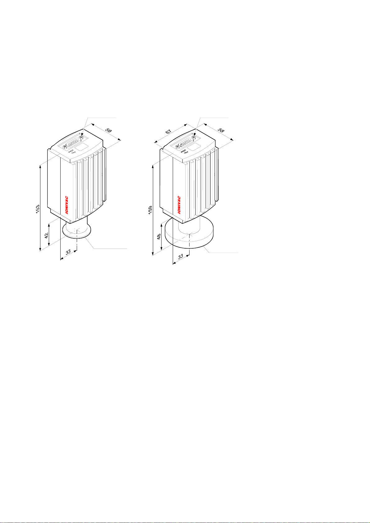
Dimensions [mm]
Part numbers Part numbers
120 90 120 92
120 91 120 94
230 030 230 031
4-40UNC 2B
Technical Data
4-40UNC 2B
DN 25 ISO-KF
DN 40 CF-R
GA09420_002_C0 – (2016-10) –
Leybold
11
Page 12
Installation
3 Installation
3.1 Vacuum Connection
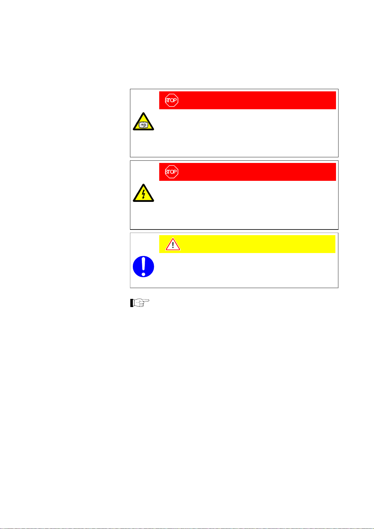
DANGER
DANGER: overpressure in the vacuum system >1 bar
Injury caused by released parts and harm caused by escaping process
gases can result if clamps are opened while the vacuum system is
pressurized.
Do not open any clamps while the vacuum system is pressurized. Use
the type of clamps which are suited to overpressure.
DANGER
The transmitter must be electrically connected to the grounded
vacuum chamber. This connection must conform to the requirements
of a protective connection according to EN 61010:
• CF connections fulfill this requirement
• For transmitters with a KF vacuum connection, use a conductive
metallic clamping ring.
Caution
Caution: vacuum component
Dirt and damages impair the function of the vacuum component.
When handling vacuum components, take appropriate measures to
• The transmitter is supplied with a built-in grid. For potentially contaminating
applications and to protect the electrodes against light and fast charged
particles, installation (→ 15) of the optional baffle is recommended (→ 43).
• The sensor can be baked at up to 150 °C. At temperatures exceeding 50 °C,
the electronics unit has to be removed (→ 14) or an extension (Option
→ 43) has to be installed.
ensure cleanliness and prevent damages.
The transmitter may be mounted in any orientation. To keep conden-
sates and particles from getting into the measuring chamber, preferably
choose a horizontal to upright position. See dimensional drawing for
space requirements (→ 11).
When installing the transmitter, make sure that the area around the
connector is accessible for the tools required for adjustment while the
transmitter is mounted (→ 37).
When installing the transmitter, allow for installing/deinstalling the
connectors and accommodation of cable loops.
GA09420_002_C0 – (2016-10) –
12
Leybold
Page 13
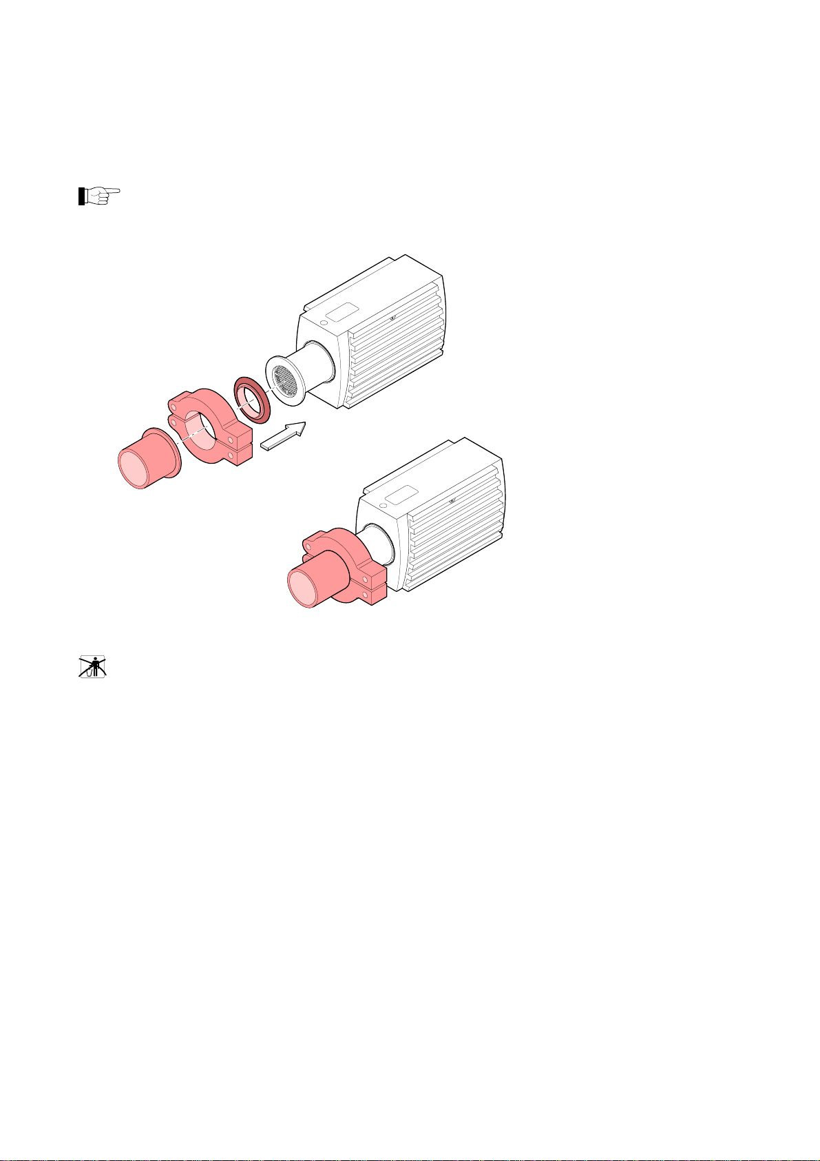
3.1.1 Making the Flange Connection
Procedure
It is recommended not to apply any vacuum grease.
Installation
The protective lid will be needed for maintenance.
GA09420_002_C0 – (2016-10) –
Leybold
13
Page 14
Installation
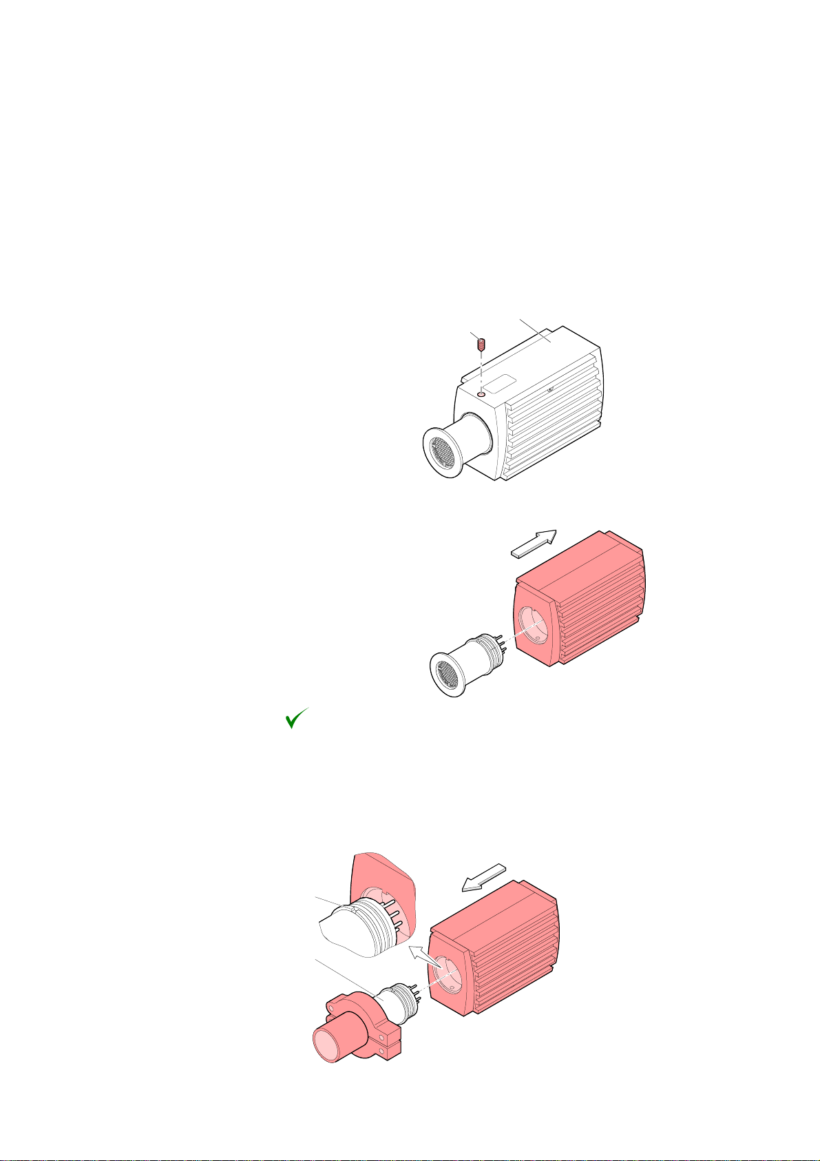
3.1.2 Removing and Installing the Electronics Unit
Required tool
• Allen key, size 2.5 mm
Removing the electronics unit
Unscrew the hexagon socket set screw (1) on the side of the electronics
unit (2).
1
2
Remove the electronics unit without twisting it.
Removal of the electronics unit is completed.
Installing the electronics unit
Place the electronics unit on the sensor (3) (be careful to correctly align the
pins and notch (4)).
GA09420_002_C0 – (2016-10) –
14
4
3
Leybold
Page 15
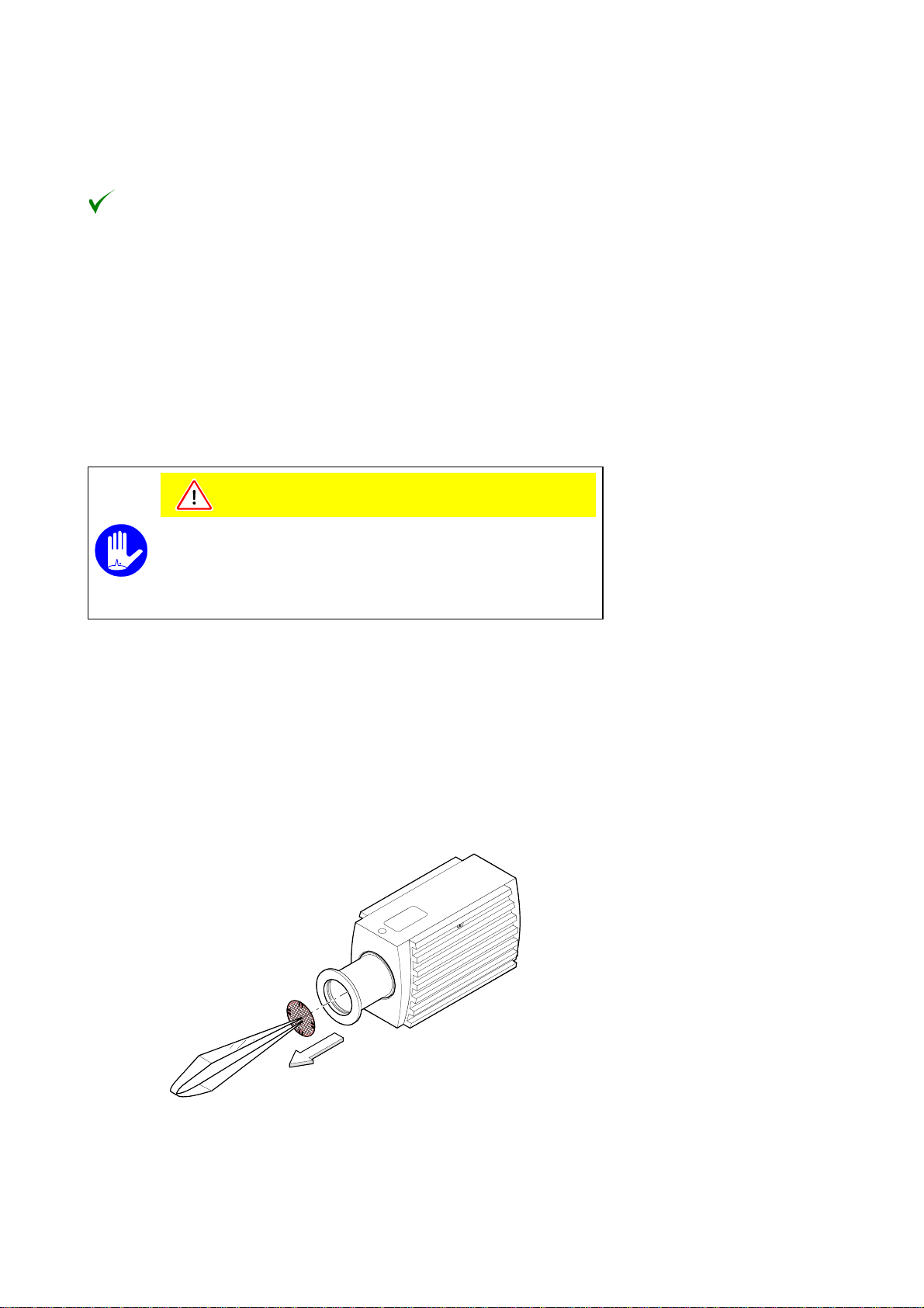
Slide the electronics unit in to the mechanical stop and lock it with the hexa-
gon socket set screw (1).
The electronics unit is now installed.
3.1.3 Using the Optional Baffle
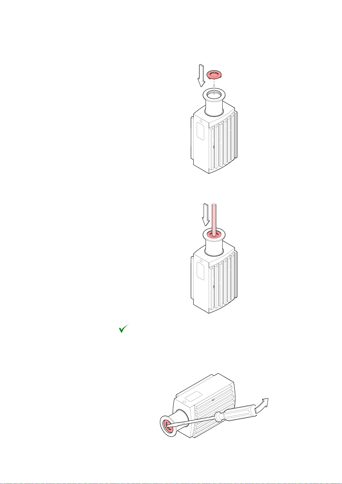
In severely contaminating processes and to protect measurement electrodes optically against light and fast charged particles, replacement of the built-in grid by the
optional baffle (→ 43) is recommended.
Installing/deinstalling
the baffle
The optional baffle will be installed at the sensor opening of the deinstalled transmitter (Deinstallation → 36).
Caution
Caution: dirt sensitive area
Touching the product or parts thereof with bare hands increases the
desorption rate.
Always wear clean, lint-free gloves and use clean tools when working
Required tools / material
in this area.
Installation
• Baffle (→ 43)
• Pointed tweezers
• Pin (e.g. pencil)
• Screwdriver No 1
Procedure
Carefully remove the grid with tweezers.
GA09420_002_C0 – (2016-10) –
Leybold
15
Page 16
Installation
Carefully place the baffle onto the sensor opening.
Using a pin, press the baffle down in the center until it catches.
The baffle is now installed (Installation of the transmitter → 12).
Deinstallation
GA09420_002_C0 – (2016-10) –
16
Carefully remove the baffle with the screwdriver.
Leybold
Page 17
3.2 Electrical Connection
3.2.1 Use With Leybold Transmitter Controllers
See Leybold sales literature and data sources for controllers and our range of
sensor cables on our internet home page (→ [6]).
Caution
Caution: data transmission errors
If the transmitter is operated with the RS232C interface and a fieldbus
interface at the same time, data transmission errors may occur.
The transmitter must not be operated with the RS232C interface and
Procedure
Profibus at the same time.
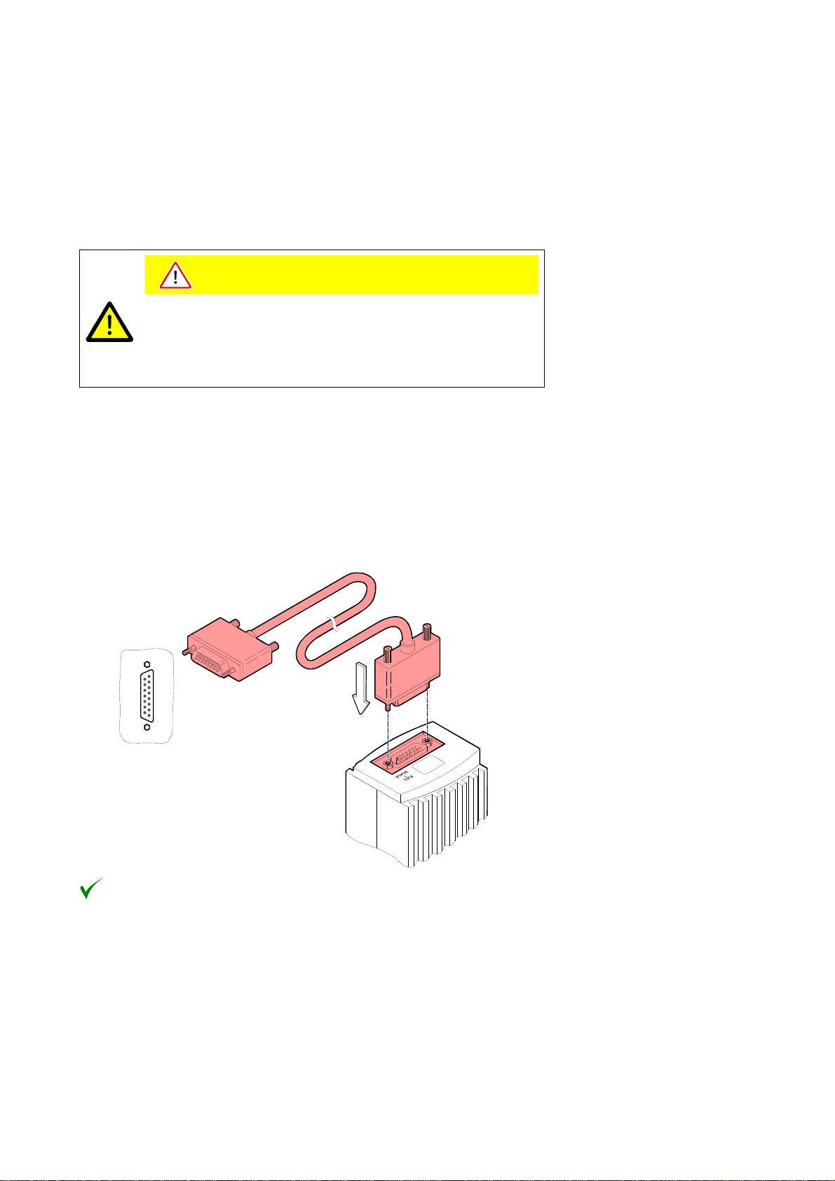
Plug the sensor connector into the transmitter and secure it with the locking
screws.
Installation
Connect the other end of the sensor cable to the Leybold controller and
secure it.
The transmitter can now be operated with the Leybold controller.
GA09420_002_C0 – (2016-10) –
Leybold
17
Page 18

Installation
3.2.2 Use With Other Controllers
The transmitter can also be operated with other controllers.
Especially the fieldbus version ITR 90 P (Profibus) is usually operated as part of a
network, controlled by a master or bus controller. In such cases, the control system
has to be operated with the appropriate software and interface protocol (→ [3]).
3.2.2.1 Making an Individual Sensor Cable
For reasons of compatibility, the expression "sensor cable" is used for all
ITR 90 versions in this document, although the pressure reading of the
ITR 90 P transmitter with fieldbus interface is normally transmitted via
Profibus.
The sensor cable is required for supplying all ITR 90 types with power.
In connection with the ITR 90 P transmitter with fieldbus interface it also
permits access to the relay contacts of the switching functions (→ 20).
Cable type
The application and length of the sensor cable have to be considered when determining the number and cross sections of the conductors (→ 8).
Procedure
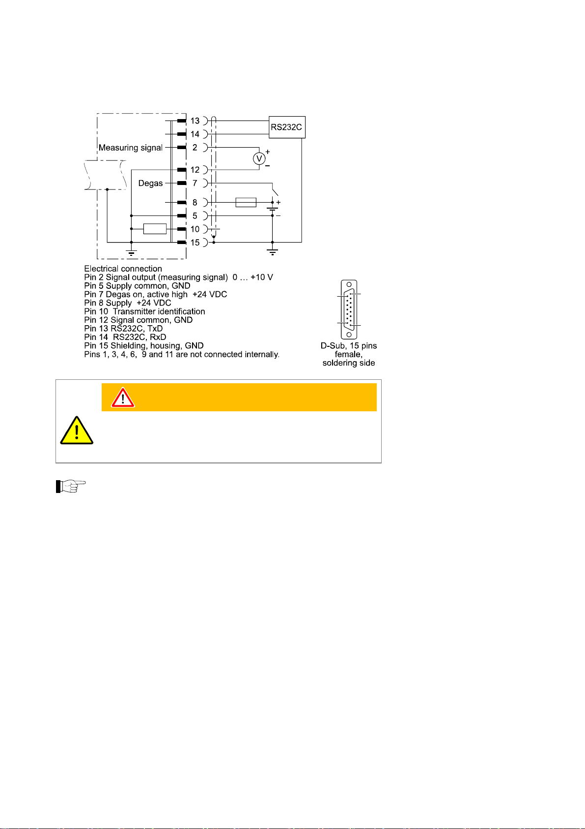
Open the cable connector (D-Sub, 15-pin, female).
Prepare the cable and solder/crimp it to the connector as indicated in the
diagram of the transmitter used:
GA09420_002_C0 – (2016-10) –
18
Leybold
Page 19
Sensor cable connection ITR 90
ITR 90
TxD
RxD
Installation
The supply common (Pin 5) and the shielding (Pin 15) must be
connected at the supply unit with protective ground.
Incorrect connection, incorrect polarity or inadmissible supply voltages
can damage the transmitter.
+U
b
42k
WARNING
1.25AT
Identification
24 V
15
9
1
8
For cable lengths up to 5 m (0.34 mm2 conductor cross-section) the
output signal can be measured directly between the positive signal output (Pin 2) and supply common GND (Pin 5) without loss of accuracy. At
greater cable lengths, differential measurement between signal output
(Pin 2) and signal common (Pin 12) is recommended.
Reassemble the cable connector.
On the other cable end, terminate the cable according to the requirements
of the transmitter controller you are using.
GA09420_002_C0 – (2016-10) –
Leybold
19
Page 20
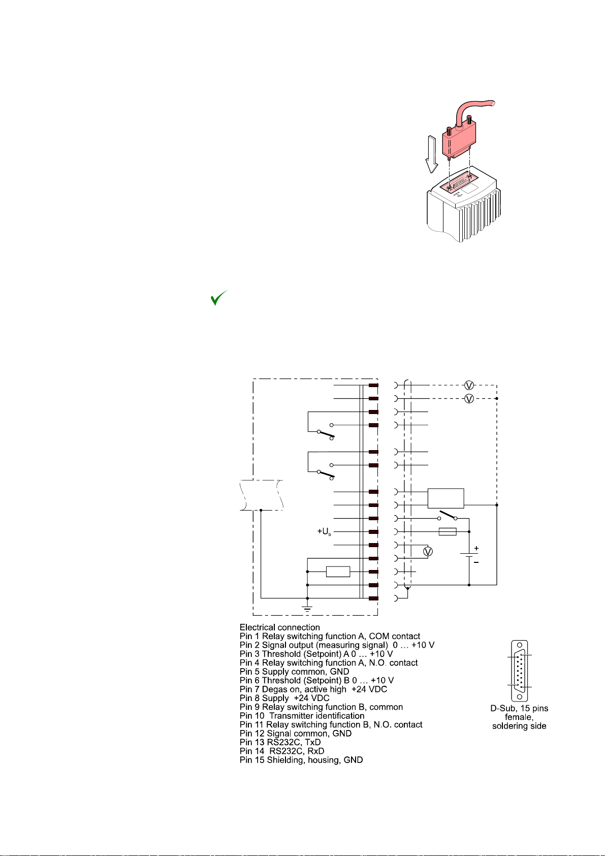
Installation
Plug the sensor connector into
the transmitter and secure it with
the locking screws.
Connect the other end of the sensor cable to the connector of the instru-
ment or transmitter controller you are using.
The transmitter can now be operated via analog and RS232C interface.
Sensor cable connection ITR 90 P
.
ITR 90 P
Measuring signal
SP A
SP B
SP A
SP B
TxD
RxD
Degas
42k
3
6
1
4
9
11
13
14
7
8
2
12
10
5
15
RS232
1.25 AT
Identification
0V
Degas
24V
9
1
GA09420_002_C0 – (2016-10) –
20
Leybold
15
8
Page 21
WARNING
The supply common (Pin 5) and the shielding (Pin 15) must be
connected at the supply unit with protective ground.
Incorrect connection, incorrect polarity or inadmissible supply
For cable lengths up to 5 m (0.34 mm2 conductor cross-section) the out-
put signal can be measured directly between the positive signal output
(Pin 2) and supply common GND (Pin 5) without loss of accuracy. At
greater cable lengths, differential measurement between signal output
(Pin 2) and signal common (Pin 12) is recommended.
Reassemble the cable connector.
voltages can damage the transmitter.
On the other cable end, terminate the cable according to the requirements
of the transmitter controller you are using.
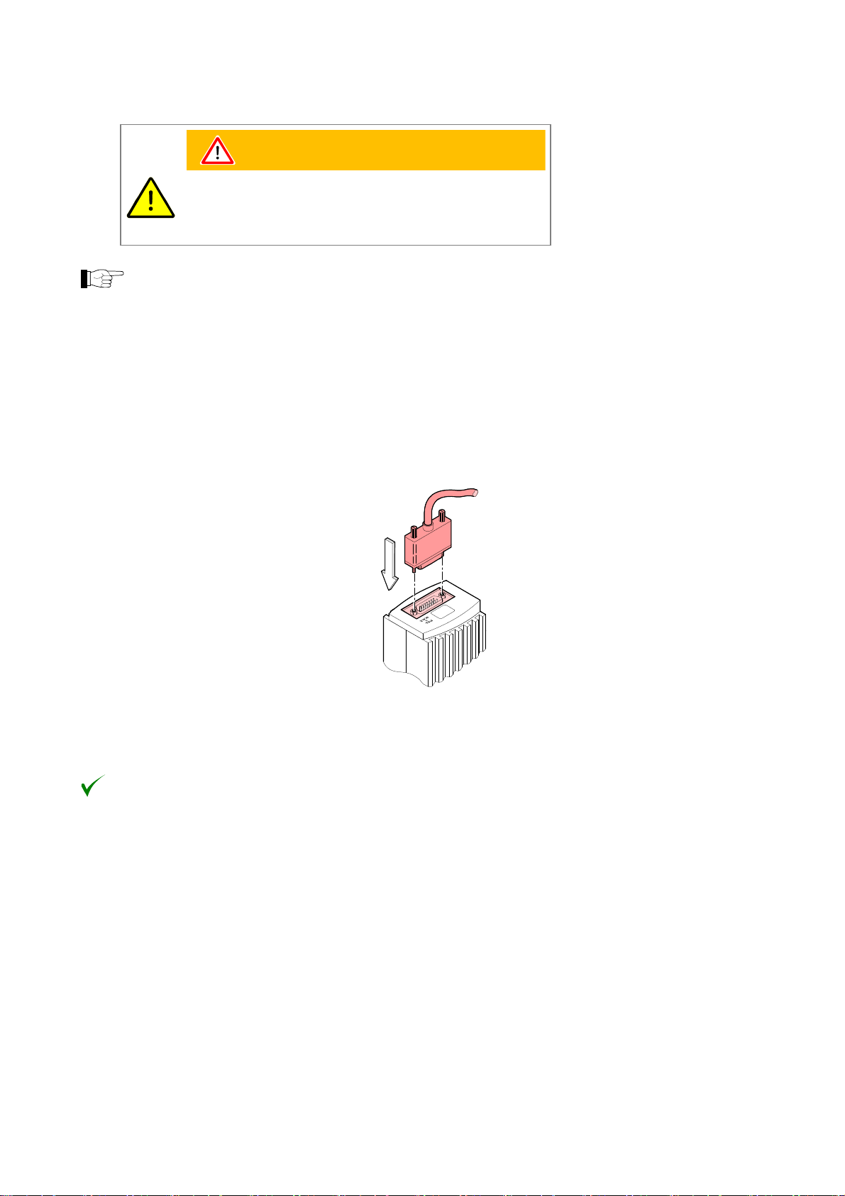
Plug the sensor connector into
the transmitter and secure it with
the locking screws.
Installation
Connect the other end of the sensor cable to the connector of the instru-
ment or transmitter controller you are using.
The transmitter can now be operated via analog and RS232C interface.
GA09420_002_C0 – (2016-10) –
Leybold
21
Page 22
Installation
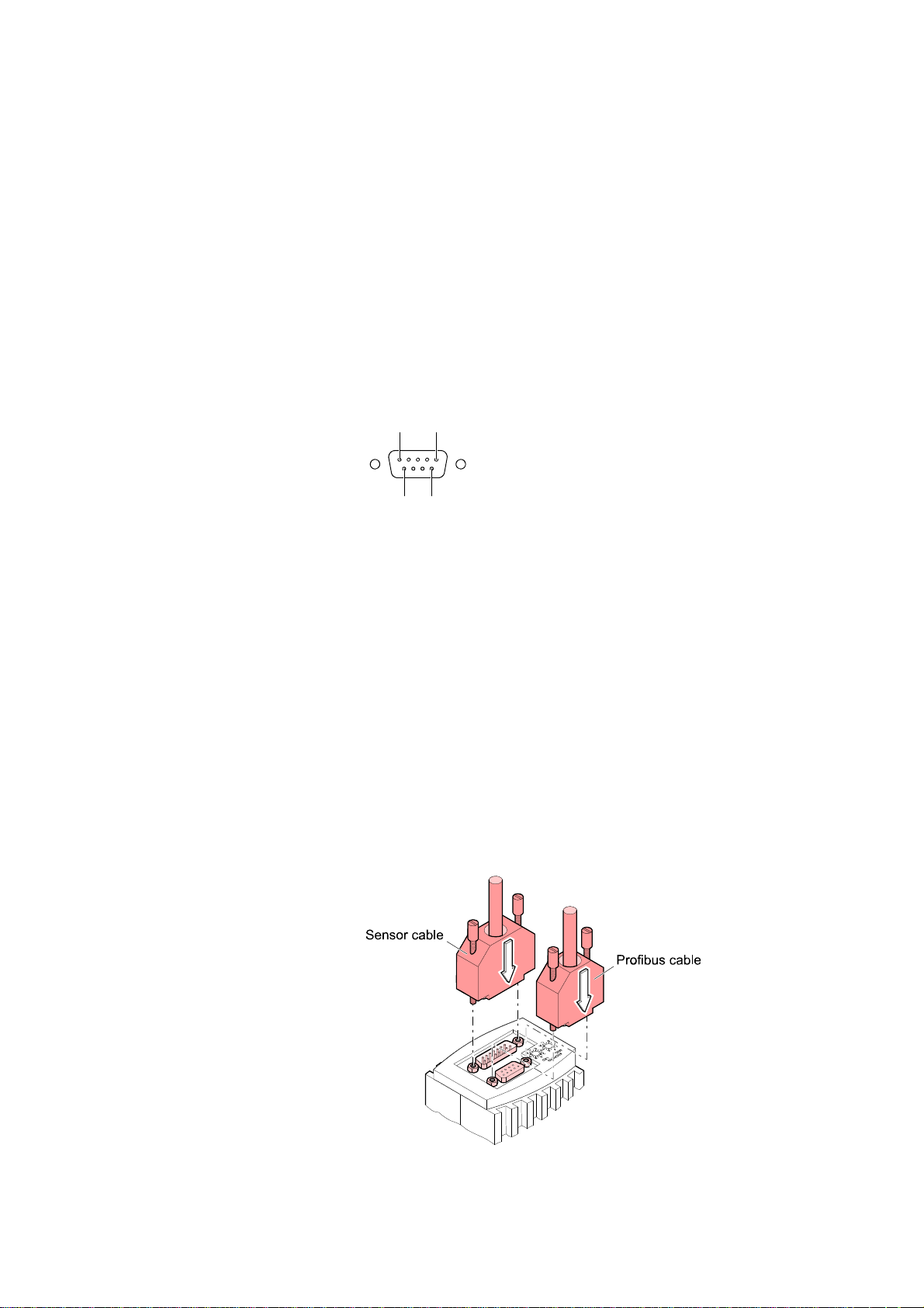
3.2.2.2 Making a Profibus Interface Cable (ITR 90 P)
For operating ITR 90 P via Profibus, an interface cable conforming to the Profibus
standard is required.
If no such cable is available, make one according to the following indications.
Cable type
Only a cable that is suited to Profibus operation may be used (→ [4], [5]).
Procedure
Make the Profibus interface cable according to the following indications:
1 5
D-Sub, 9-pin
male, soldering side
6 9
Pin Function (BPG400-SP)
1 Do not connect
2 Do not connect
3 RxD/TxD-P
4 CNTR-P
5 DGND
6 VP
1)
2)
2)
7 Do not connect
8 RxD/TxD-N
9 Do not connect
1)
Only to be connected if an optical link module is used.
2)
Only required as line termination for devices at both ends of bus cable
(→ [4]).
GA09420_002_C0 – (2016-10) –
22
Plug the Profibus (and sensor) cable connector into the transmitter.
Leybold
Page 23
Installation
Lock the Profibus (and sensor) cable connector.
The transmitter can now be operated via Profibus interface (→ 32).
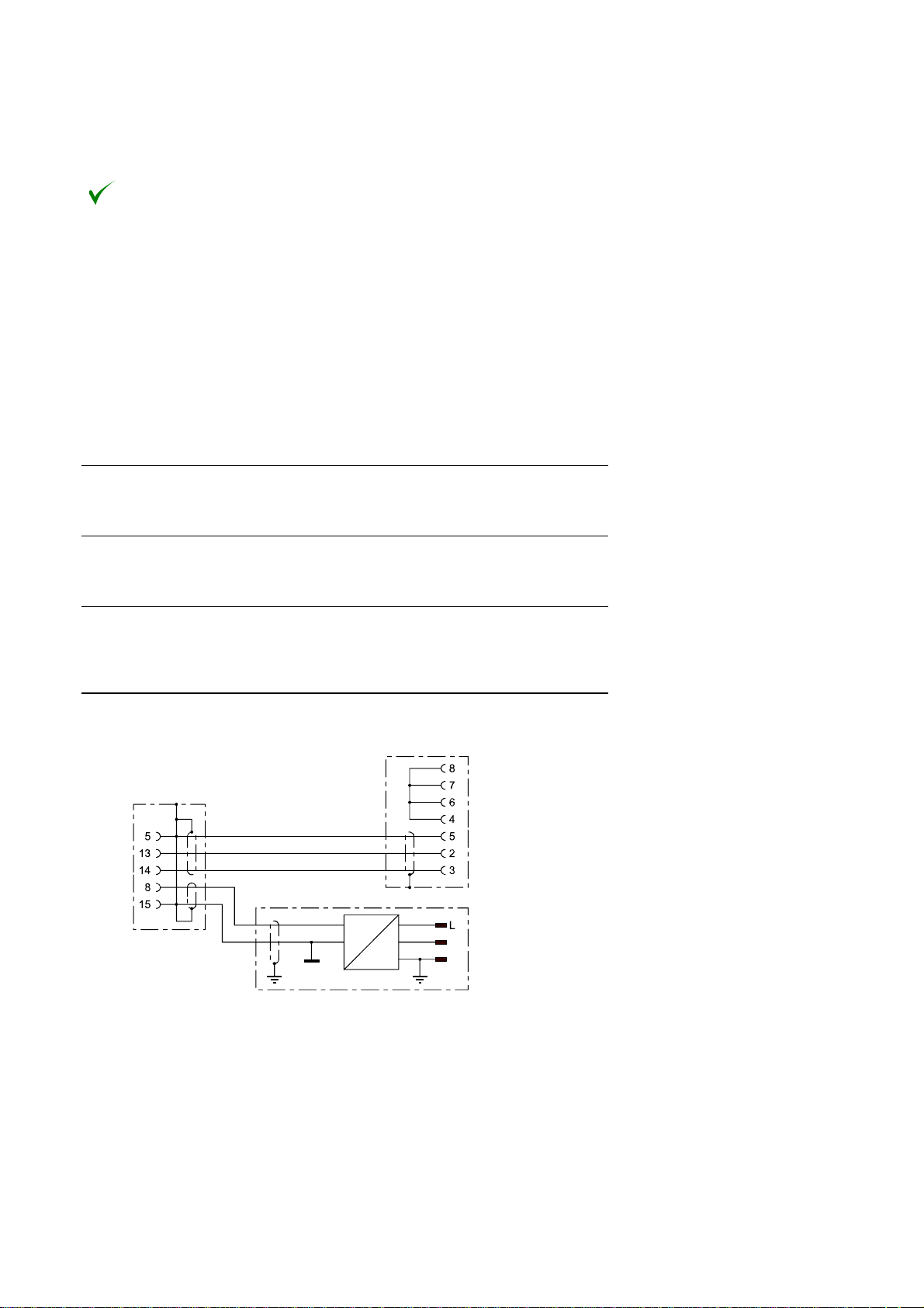
3.2.3 Using the Optional Power Supply (With RS232C Line)
The optional 24 V power supply (→ 43) allows RS232C operation of the ITR 90
transmitter with any suitable instrument or control device.
The instrument or control device needs to be equipped with a software that supports the RS232C protocol of the transmitter (→ 29).
Technical data
Mains connection
Mains voltage 90 … 250 VAC 50 … 60 Hz
Mains cable 1.8 meter (Schuko DIN and U.S. con-
Output (operating voltage of transmitter)
Voltage 21 … 27 VDC, set to 24 VDC
Current Max. 1.5 A
Transmitter connection
Connector D-Sub, 15-pin, female
24 VDC cable 5 m, black
Connection of the instrument or control
device
RS232C connection D-Sub, 9-pin, female
Cable 5 m, black, 3 conductors, shielded
Wiring diagram
nectors)
ITR 90
D-Sub,
15 pins
PE
+24 V
GND
DC
AC
RS232C
D-Sub, 9 pins
Mains
N
90 ... 250 VAC
PE
50 ... 60 Hz
GA09420_002_C0 – (2016-10) –
Leybold
23
Page 24
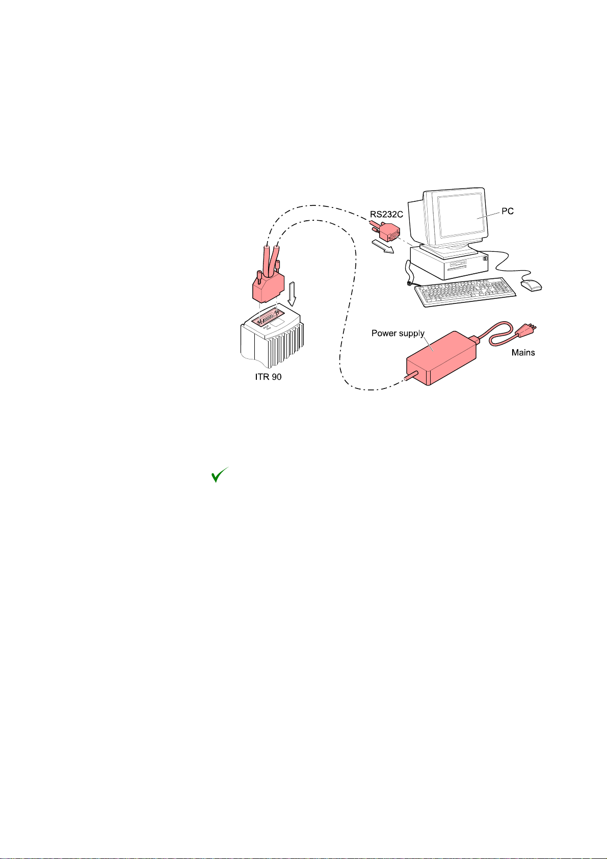
Installation
Connecting the power supply
Connect the transmitter to the power supply and lock the connector with the
screws.
Connect the RS232C line to the instrument or control device and lock the
connector with the screws.
Connect the power supply to the mains.
Turn the power supply on.
The transmitter can now be operated via RS232C interface (→ 29).
GA09420_002_C0 – (2016-10) –
24
Leybold
Page 25
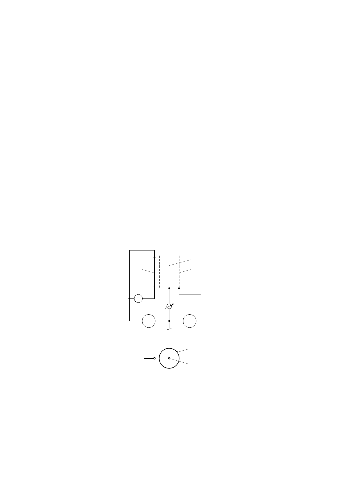
4 Operation
4.1 Measuring Principle, Measuring Behavior
The ITR 90 vacuum transmitters consist of two separate measuring systems (hot
cathode Bayard-Alpert (BA) and Pirani).
Bayard-Alpert
The BA measuring system uses an electrode system according to Bayard-Alpert
which is designed for a low x-ray limit.
The measuring principle of this measuring system is based on gas ionization.
Electrons emitted by the hot cathode (F) ionize a number of molecules proportional
to the pressure in the measuring chamber. The ion collector (IC) collects the thus
generated ion current I
+
and feeds it to the electrometer amplifier of the
measurement instrument. The ion current is dependent upon the emission current
Ie, the gas type, and the gas pressure p according to the following relationship:
+
I
= Ie × p × C
Factor C represents the sensitivity of the transmitter head. It is generally specified
.
for N
2
The lower measurement limit is 5×10
To usefully cover the whole range of 5×10
-10
mbar (transmitter metal sealed).
-10
mbar … 10-2 mbar, a low emission
current is used in the high pressure range (fine vacuum) and a high emission current is used in the low pressure range (high vacuum). The switching of the emission current takes place at decreasing pressure at approx. 7.2×10
creasing pressure at approx. 3.2×10
can temporarily (<2 s) deviate from the specified accuracy.
-5
mbar. At the switching threshold, the ITR 90
-6
mbar, at in-
IC
ECF
+– +–
(Degas 250V)
200V40V
Diagram of the BA measuring system
EC
F hot cathode (filament)
IC ion collector
EC anode (electron collector)
F
IC
Operation
GA09420_002_C0 – (2016-10) –
Leybold
25
Page 26
Operation
Pirani
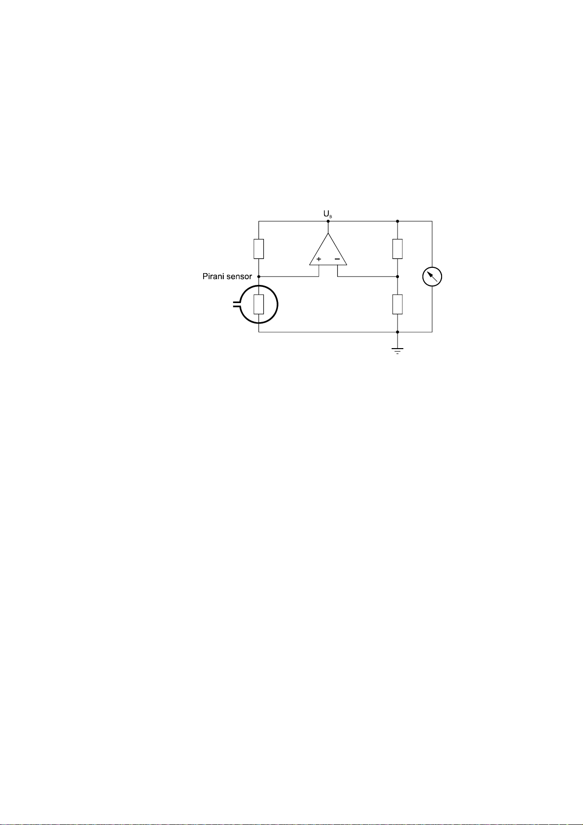
Within certain limits, the thermal conductibility of gases is pressure dependent. This
physical phenomenon is used for pressure measurement in the thermal conductance vacuum meter according to Pirani. A self-adjusting bridge is used as measuring circuit (→ schematic). A thin tungsten wire forms the sensor element. Wire
resistance and thus temperature are kept constant through a suitable control circuit. The electric power supplied to the wire is a measure for the thermal conductance and thus the gas pressure. The basic principle of the self-adjusting bridge
circuit is shown in the following schematic.
Schematic
The bridge voltage UB is a measure for the gas pressure and is further processed
electronically (linearization, conversion).
Measuring range
The ITR 90 transmitters continuously cover the measuring range
-10
5×10
mbar … 1000 mbar.
• The Pirani constantly monitors the pressure.
• The hot cathode (controlled by the Pirani) is activated only at pressures
<2.4×10
-2
mbar.
If the measured pressure is higher than the switching threshold, the hot cathode is
switched off and the Pirani measurement value is output.
-2
If the Pirani measurement drops below the switching threshold (p = 2.4×10
the hot cathode is switched on. After heating up, the measured value of the hot
cathode is fed to the output. In the overlapping range of 5.5×10
-3
… 2.0×10⁻² mbar,
mbar),
the output signal is generated from both measurements.
-2
Pressure rising over the switching threshold (p = 3.2×10
mbar) causes the hot
cathode to be switched off. The Pirani measurement value is output.
Gas type dependence
The output signal is gas type dependent. The characteristic curves are accurate for
dry air, N
and O2. They can be mathematically converted for other gases
2
(→ Appendix B).
GA09420_002_C0 – (2016-10) –
26
Leybold
Page 27

4.2 Operational Principle of the Transmitter
The measuring currents of the Bayard-Alpert and Pirani sensor are converted into
a frequency. A micro-controller converts this frequency into a digital value representing the measured total pressure. After further processing this value is available
as analog measurement signal (0 … +10 V) at the output (sensor cable connector
Pin 2 and Pin 12). The maximum output signal is internally limited to +10 V (
≙
atmosphere). The measured value can be read as digital value through the
RS232C interface (Pins 13, 14, 15) (→ 29). transmitters with a display show the
value as pressure. The default setting of the displayed pressure unit is mbar. It can
be modified via the RS232C interface (→ 29).
In addition to converting the output signal, the micro controller's functions include
monitoring of the emission, calculation of the total pressure based on the measurements of the two sensors, and communication via RS232C interface.
4.3 Putting the Transmitter Into Operation
When the operating voltage is supplied (→ Technical Data), the output signal is
available between Pin 2 (+) and Pin 12 (–) of the sensor cable connector
(Relationship output signal – pressure → Appendix A).
Allow for a stabilizing time of approx. 10 min. Once the transmitter has been
switched on, permanently leave it on irrespective of the pressure.
Communication via the digital interface is described in a separate section.
4.4 Degas
Operation
Contamination
Transmitter failures due to contamination or wear and tear as well as
expendable parts (filaments) are not covered by the warranty.
Deposits on the electrode system of the BA transmitter can lead to unstable
measurement readings.
The degas process allows in-situ cleaning of the electrode system by heating the
electron collector grid to approx. 700 °C by electron bombardment.
Depending on the application, this function can be activated by the system control
via a digital interface. The ITR 90 automatically terminates the degas process after
3 minutes, if it has not been stopped before.
The degas process should be run at pressures below 7.2×10⁻⁶ mbar
(emission current 5 mA).
For a repeated degas process, the control signal first has to change from ON
(+24 V) to OFF (0 V), to then start degas again with a new ON (+24 V) command. It
is recommended that the degas signal be set to OFF again by the system control
after 3 minutes of degassing, to achieve an unambiguous operating status.
GA09420_002_C0 – (2016-10) –
Leybold
27
Page 28
Operation
4.5 Display
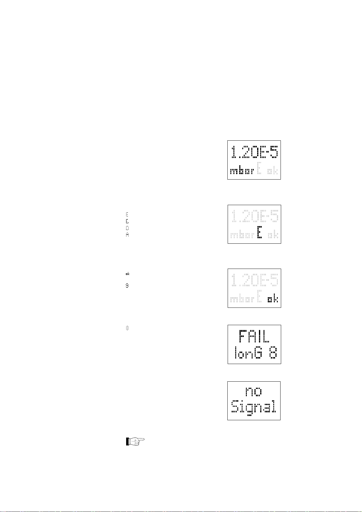
The transmitters with part numbers
120 91 and
120 94
have a built-in two-line display with an LCD matrix of 32×16 pixels. The first line
shows the pressure, the second line the pressure unit, the function and possible
errors. The background illumination is usually green, in the event of an error, it
changes to red. The pressure is displayed in mbar (default), Torr or Pa. The pressure unit can be changed via RS232C interface (→ 29).
Pressure display
Pressure reading, pressure unit
Function display
(none) Pirani operation
Emission 25 A
Emission 5 mA
Degas
1000 mbar adjustment (Pirani)
Error display
no error
(green background illumination)
Pirani sensor error
(red background illumination)
BA sensor error
(red background illumination)
GA09420_002_C0 – (2016-10) –
28
Internal data connection failure
(red background illumination)
What to do in case of problems → 39.
Leybold
Page 29
4.6 RS232C Interface
The built-in RS232C interface allows transmission of digital measurement data and
instrument conditions as well as the setting of instrument parameters.
Caution
Caution: data transmission errors
If the transmitter is operated with the RS232C interface and a fieldbus
interface at the same time, data transmission errors may occur.
The transmitter must not be operated with the RS232C interface and
4.6.1 Description of the Functions
The interface works in duplex mode. A nine byte string is sent continuously without
a request approx. every 20 ms.
Commands are transmitted to the transmitter in a five byte input (receive) string.
Operational parameters
Profibus at the same time.
Operation
• Data rate
• Byte
9600 Baud set value, no handshake
8 data bits
1 stop bit
Electrical connections
• TxD
• RxD
• GND
Pin 13
Pin 14
Pin 5
(Sensor cable connector)
4.6.1.1 Output String (Transmit)
The complete output string (frame) is nine bytes (byte 0 … 8). The data string is
seven bytes (byte 1 … 7).
Format of the output string
Byte No Function Value Comment
0 Length of data string 7 (Set value)
1 Page number 5 (For ITR 90)
2 Status
3 Error
4 Measurement high byte 0 … 255
5 Measurement low byte 0 … 255
6 Software version 0 … 255
→ Status byte
→ Error byte
→ Calculation of pressure value
→ Calculation of pressure value
→ Software version
7 Sensor type 10 (For ITR 90)
8 Check sum 0 … 255
→ Synchronization
GA09420_002_C0 – (2016-10) –
Leybold
29
Page 30
Operation
Synchronization
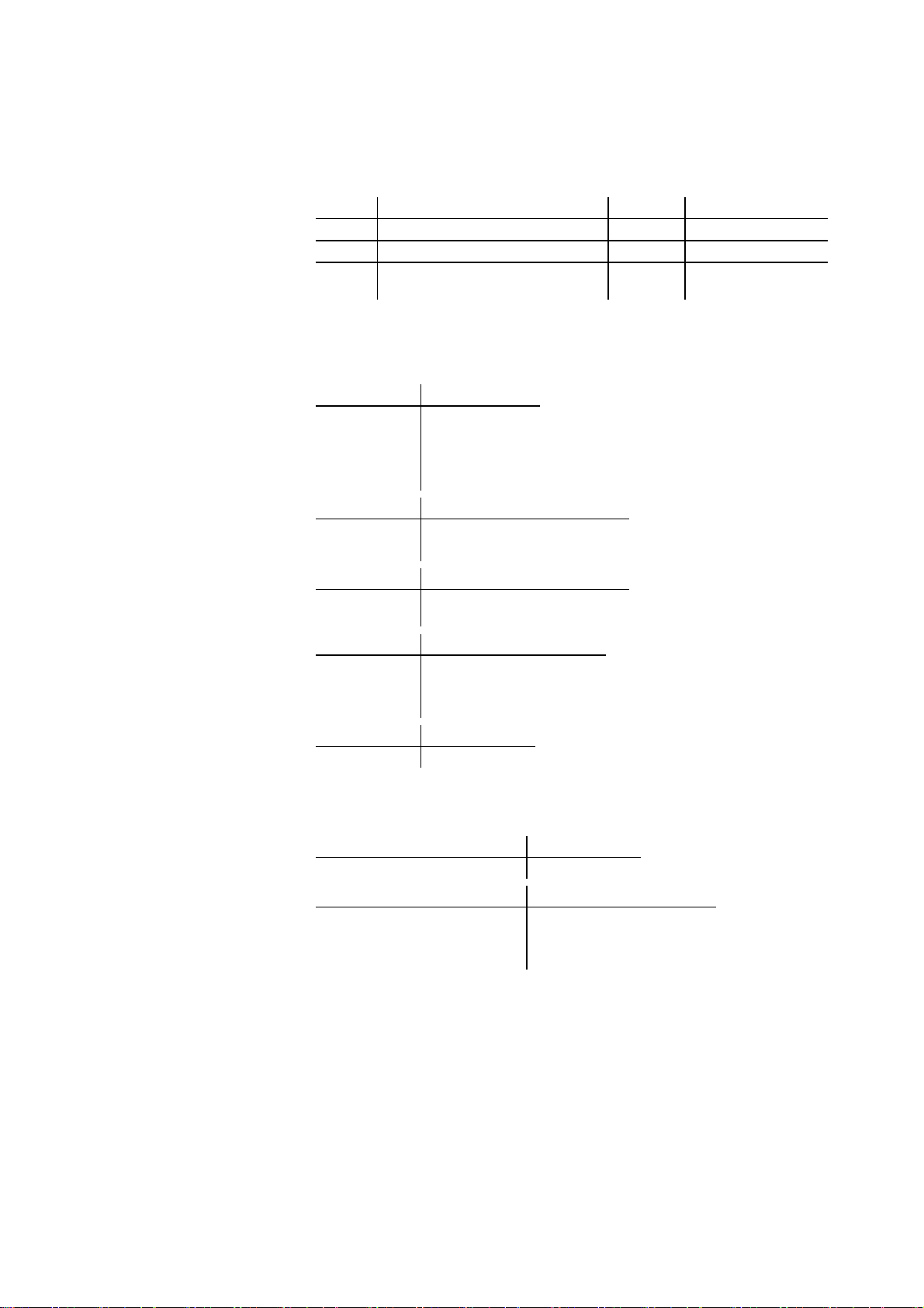
Synchronization of the master is achieved by testing three bytes:
Byte No Function Value Comment
0 Length of data string 7 Set value
1 Page number 5 (For ITR 90)
8 Check sum of bytes No 1 … 7 0 … 255 Low byte of check
1)
High order bytes are ignored in the check sum.
sum
1)
Status byte
Bit 1 Bit 0 Definition
0 0 Emission off
0 1
Emission 25 μA
1 0 Emission 5 mA
1 1 Degas
Bit 2 Definition
0 1000 mbar adjustment off
1 1000 mbar adjustment on
Bit 3 Definition
0 ⇔ 1
Toggle bit, changes with every
string received correctly
Bit 5 Bit 4 Definition
0 0 Current pressure unit mbar
0 1 Current pressure unit Torr
1 0 Current pressure unit Pa
Bit 7 Bit 6 Definition
x x Not used
Error byte
Bit 3 Bit 2 Bit 1 Bit 0 Definition
x x x x Not used
Bit 7 Bit 6 Bit 5 Bit 4 Definition
0 1 0 1 Pirani adjusted poorly
1 0 0 0 BA error
1 0 0 1 Pirani error
Software version
GA09420_002_C0 – (2016-10) –
30
The software version of the transmitter can be calculated from the value of byte 6
of the transmitted string according to the following rule:
Version No = Value
(Example: According to the above formula, Value
Byte 6
/ 20
of 32 means software ver-
Byte 6
sion 1.6)
Leybold
Page 31

Calculation of the pressure value
The pressure can be calculated from bytes 4 and 5 of the transmitted string. Depending on the currently selected pressure unit (→ byte 2, bits 4 and 5), the appropriate rule must be applied.
As result, the pressure value results in the usual decimal format.
((high byte × 256 + low byte) / 4000 - 12.5)
= 10
((high byte × 256 + low byte) / 4000 - 12.625)
((high byte × 256 + low byte) / 4000 - 10.5)
p
mbar
p
= 10
Torr
pPa = 10
Example
The example is based on the following output string:
Byte No 0 1 2 3 4 5 6 7 8
Value 7 5 0 0 242 48 20 10 69
The instrument or controller (receiver) interprets this string as follows:
Byte No Function Value Comment
0 Length of data
7 (Set value)
string
1 Page number 5 ITR 90
2 Status 0
Emission = off
Pressure unit = mbar
3 Error 0
Measurement
4
5
High byte
Low byte
6 Software version 20
No error
Calculation of the pressure:
242
48
((242 × 256 + 48) / 4000 - 12.5)
p = 10
Software version = 20 / 20 = 1.0
= 1000 mbar
7 Sensor type 10 ITR 90
8 Check sum 69
5 + 0 + 0 + 242 + 48 + 20 + 10 =
≙ 01 45
325
dec
hex
High order byte is ignored
Check sum = 45
hex
≙ 69
dec
4.6.1.2 Input String (Receive)
Operation
For transmission of the commands to the transmitter, a string (frame) of five bytes
is sent (without <CR>). Byte 1 to byte 3 form the data string.
Format of the input string
Byte no Function Value Comment
0 Length of data string 3 (Set value)
1 Data
2 Data
3 Data
4 Check sum
1)
High order bytes are ignored in the check sum.
(from bytes No 1 … 3) 0 … 255
→ admissible input strings
→ admissible input strings
→ admissible input strings
(low byte of sum)
1)
GA09420_002_C0 – (2016-10) –
Leybold
31
Page 32
Operation
Admissible input strings
For commands to the transmitter, six defined strings are used:
Byte No
Command 0 1 2 3 4 2)
Set the unit mbar in the display 3 16 62 0 78
Set the unit Torr in the display 3 16 62 1 79
Set the unit Pa in the display 3 16 62 2 80
Power-failure-safe storage of current unit 3 32 62 62 156
Switch degas on
3 16 93 148 1
(switches itself off after 3 minutes)
Switch degas off before 3 minutes 3 16 93 105 214
2)
Only low order byte of sum (high order byte is ignored).
4.7 Profibus Interface (ITR 90 P)
This interface allows operation of ITR 90 P with part number
230030 and
230031
in connection with other devices that are suited for Profibus operation. The physical
interface and interface firmware of ITR 90 P comply with the Profibus standard
(→ [4], [5]).
Two adjustable switching functions are integrated in the ITR 90 P. The corresponding relay contacts are available at the sensor cable connector (→ 20, 34).
The basic sensor and sensor electronics of all ITR 90 transmitters are identical.
Caution
Caution: data transmission errors
If the transmitter is operated via RS232C interface and Profibus
interface at the same time, data transmission errors may occur.
The transmitter must not be operated via RS232C interface and
4.7.1 Description of the Functions
Via this interface, the following and further data are exchanged in the standardized
Profibus protocol (→ [3]):
• Pressure reading
• Pressure unit (Torr, mbar, Pa)
• Degas function
• Transmitter adjustment
• Status and error messages
• Status of the switching functions
Profibus interface at the same time.
GA09420_002_C0 – (2016-10) –
32
Leybold
Page 33

4.7.2 Operating Parameters
As the Profibus protocol is highly complex, the parameters and programming of
ITR 90 P are described in detail in the separate Interface Manual (→ [3]).
4.7.2.1 Operating Software
For operating the transmitter via Profibus, prior installation of the ITR 90 specific
GSD file is required on the bus master side. This file can be downloaded from the
CD ROM, which is enclosed in scope of delivery of the transmitter.
4.7.2.2 Node Address Setting
For unambiguous identification of the transmitter in a Profibus environment, a node
address is required. The node address setting is made on the transmitter.
The node address (0 … 125
(00 … 7D
) via the "ADDRESS", "MSD", and "LSD" switches.
hex
) is set in hexadecimal form
dec
The node address is polled by the firmware when the transmitter is switched on. If the setting deviates from the stored
value, the new value is taken over into the NVRAM. If a value
>7D
hex
(>125
) is entered, the node address setting currently
dec
stored in the device remains valid but it can now be defined via
Profibus ("Set slave Address", → [3]).
Electrical connections
Operation
The transmitter is connected to Profibus via the 9-pin Profibus connector (→ 22).
GA09420_002_C0 – (2016-10) –
Leybold
33
Page 34
Operation
4.8 Switching Functions (ITR 90 P)
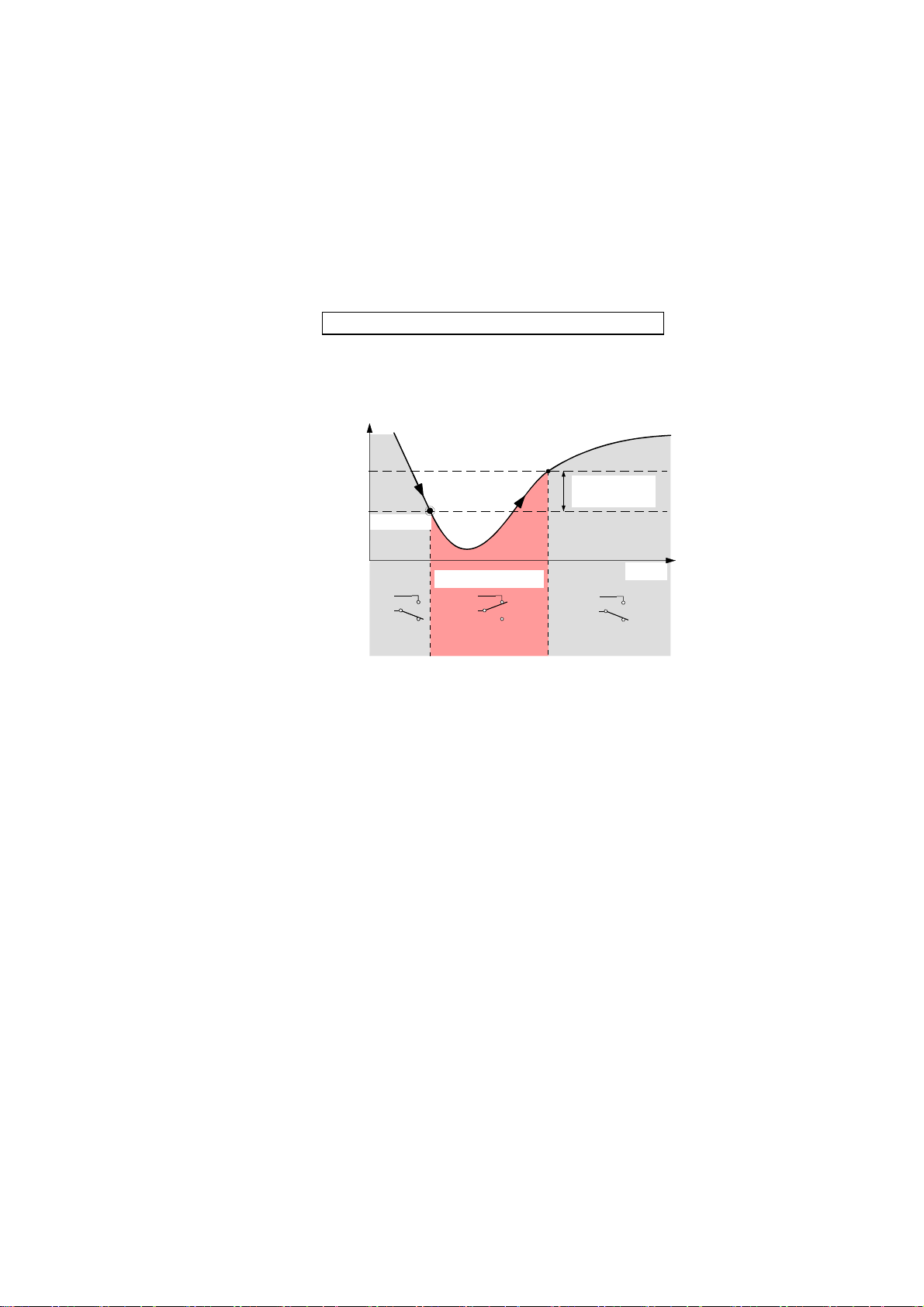
The transmitter ITR 90 P has two independent, manually settable switching
functions. Each switching function has a floating normally open relay contact. The
relay contacts are accessible at the sensor cable connector (→ 20).
The threshold values of switching functions A and B can be set within the pressure
range 1×10
-9
mbar … 100 mbar via potentiometers "SETPOINT A" and
"SETPOINT B".
Calculating the threshold voltage
U
Threshold
= 0.75 × (log p
Setpoint
– c) + 7.75
Constant c is pressure unit dependent (→ Appendix A).
Measuring signal
(Pressure p)
U
Threshold
(Setpoint A, B)
u
s
a
e
M
Hysteresis
10% U
a
v
d
e
r
Threshold
e
u
l
Off
Time t
Switching function
Off
On
The hysteresis of the switching functions is 10% of the threshold setting.
4.8.1 Setting the Switching Functions
The threshold values of the two switching functions "SETPOINT A" and
"SETPOINT B" are set locally on the potentiometers of the transmitter that are
accessible via the openings on one side of the transmitter housing.
Required tools
• Voltmeter
• Ohmmeter or continuity checker
• Screwdriver, max. ø2.5 mm
Procedure
The procedure for setting thresholds is identical for both switching functions.
GA09420_002_C0 – (2016-10) –
34
Put the transmitter into operation.
Leybold
Page 35
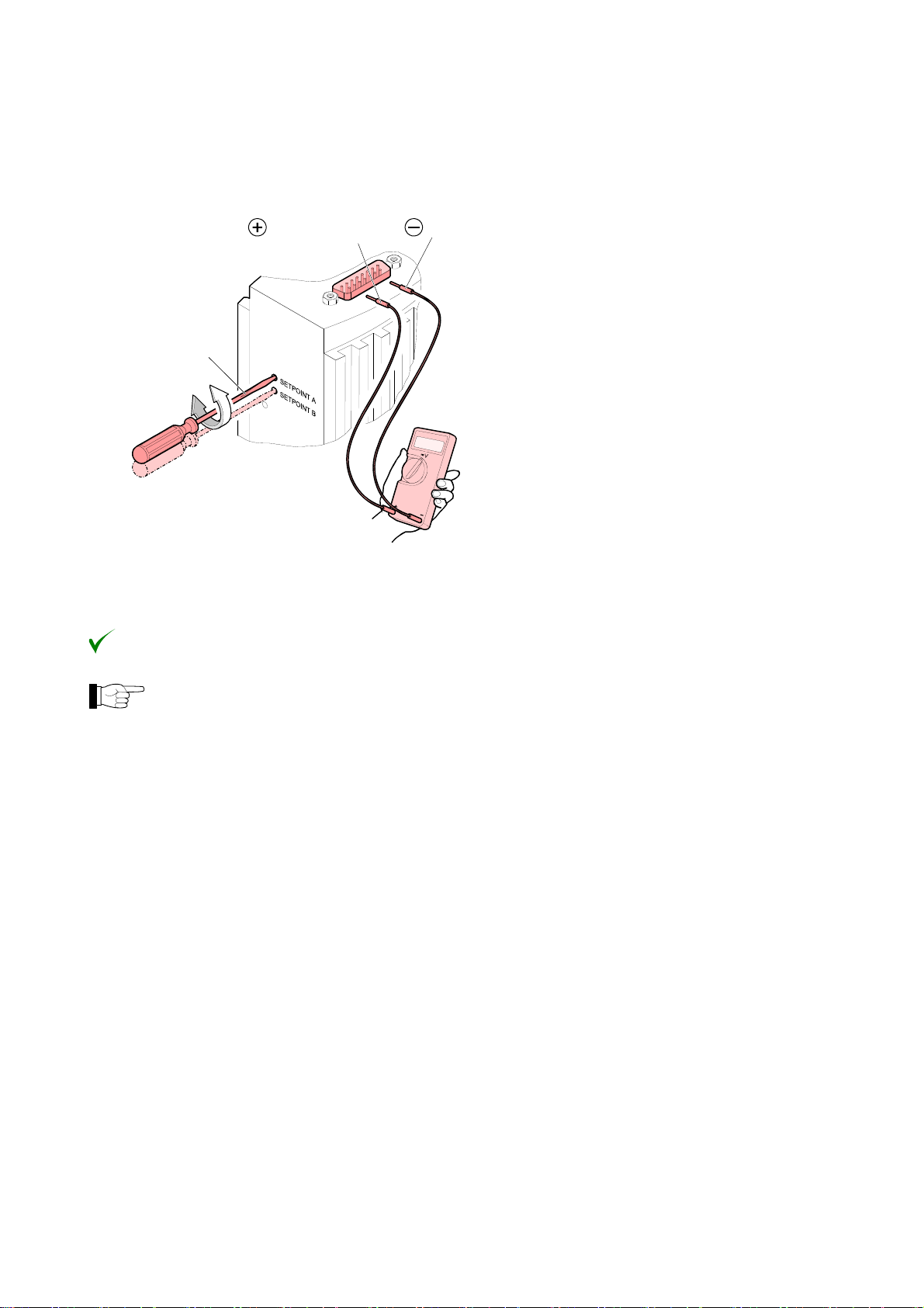
Connect the + lead of a voltmeter to the threshold measurement point of the
selected switching function ("Setpoint A" Pin 3, "Setpoint B" Pin 6) and
its – lead to Pin 5.
Setpoint A Pin 3
Setpoint B Pin 6
max. ø2.5
Pin 5
Operation
Using a screwdriver (max. ø2.5 mm), set the voltage of the selected
switching function (Setpoint A, B) to the desired value U
Setting of the switching functions is now concluded.
There is no local visual indication of the statuses of the switching func-
tions. However, a functional check of the switching functions (On/Off)
can be made with one of the following methods:
• Reading the status via fieldbus interface → [3].
• Measurement of the relay contacts at the sensor cable connector
with a ohmmeter/continuity checker (→ 20).
Threshold
.
GA09420_002_C0 – (2016-10) –
Leybold
35
Page 36
Deinstallation
5 Deinstallation
Procedure
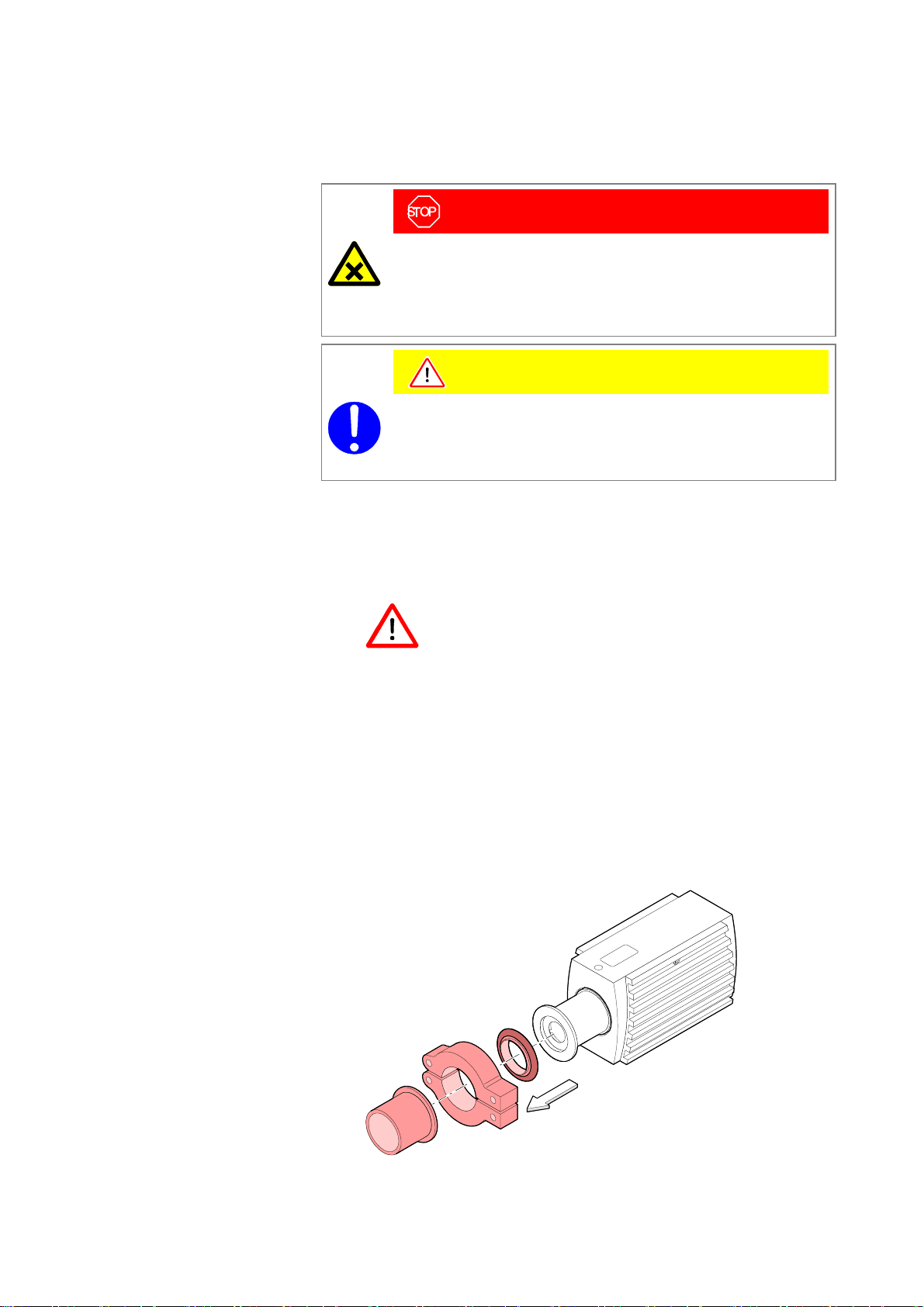
DANGER
Caution: contaminated parts
Contaminated parts can be detrimental to health and environment.
Before beginning to work, find out whether any parts are contaminated. Adhere to the relevant regulations and take the necessary precautions when handling contaminated parts.
Caution
Caution: vacuum component
Dirt and damages impair the function of the vacuum component.
When handling vacuum components, take appropriate measures to
ensure cleanliness and prevent damages.
Vent the vacuum system.
Before taking the transmitter out of operation, make sure that this
has no adverse effect on the vacuum system.
Depending on the programming of the superset controller, faults
may occur or error messages may be triggered.
Follow the appropriate shut-down and starting procedures.
Take transmitter out of operation.
Disconnect all cables from the transmitter.
Remove transmitter from the vacuum system and replace the protective lid.
GA09420_002_C0 – (2016-10) –
36
Leybold
Page 37
Maintenance, Repair
6 Maintenance, Repair
6.1 Maintenance
DANGER
Caution: contaminated parts
Contaminated parts can be detrimental to health and environment.
Before beginning to work, find out whether any parts are contaminated. Adhere to the relevant regulations and take the necessary pre-
The product is maintenance-free, If clean operating conditions are met.
6.1.1 Cleaning the Transmitter
Small deposits on the electrode system can be removed by baking the anode
(Degas → 27). In the case of severe contamination, the baffle can be exchanged
easily (→ 15). The sensor itself cannot be cleaned and needs to be replaced in
case of severe contamination (→ 41).
A slightly damp cloth normally suffices for cleaning the outside of the unit. Do not
use any aggressive or scouring cleaning agents.
cautions when handling contaminated parts.
Make sure that no liquid can penetrate the product. Allow the product to
dry thoroughly before putting it into operation again.
Transmitter failures due to contamination or wear and tear as well as
expendable parts (filaments) are not covered by the warranty.
6.2 Adjusting the Transmitter
The transmitter is factory-calibrated. Through the use in different climatic conditions, fitting positions, aging or contamination (→ 27) and after exchanging the
sensor (→ 41) a shifting of the characteristic curve can occur and readjustment
can become necessary. Only the Pirani part can be adjusted.
6.2.1 Adjustment at Atmospheric Pressure
At the push of a button the digital value and thus the analog output are adjusted
electronically to 10 V at atmospheric pressure.
Adjustment is necessary if
• at atmospheric pressure, the output signal is <10 V
• the display reads < atmospheric pressure (if the transmitter has a display)
• at atmosphere, the digital value of the RS232C interface is < atmospheric pres-
sure
• at atmosphere, the digital value received by the bus controller of the fieldbus
transmitter (Profibus) is < atmospheric pressure
• when the vacuum system is vented, the output voltage reaches 10 V (limited to
10 V by the software) before the measured pressure has reached atmosphere
• when the vacuum system is vented, the digital value of the RS232C interface
reaches its maximum before the measured pressure has reached atmosphere.
GA09420_002_C0 – (2016-10) –
Leybold
37
Page 38
Maintenance, Repair
• when the vacuum system is vented, the digital value received by the bus controller of the fieldbus (Profibus) reaches its maximum before the measured
pressure has reached atmosphere.
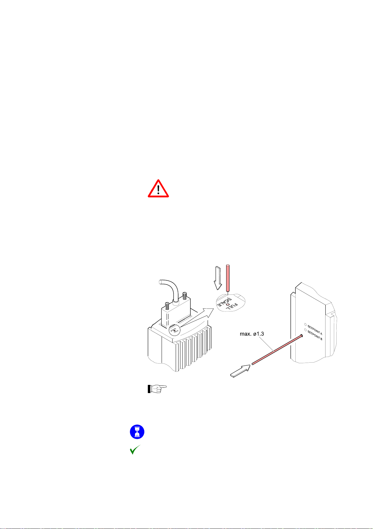
Required tools
• Pin approx. ø1.3 × 50 mm (e.g. a bent open paper clip)
Procedure
The transmitter ITR 90 P is mechanically slightly different from the BPG400. The
adjustment opening of ITR 90 P is on one side of the transmitter housing. However,
the adjustment procedure is the same for all transmitter versions.
Operate transmitter for approx. 10 minutes at atmospheric pressure.
If the transmitter was operated before in the BA range, a cooling-
down time of approx. 30 minutes is to be expected (transmitter
temperature = ambient temperature).
Insert the pin through the opening marked <FULL SCALE> and push the
button inside for at least 5 s.
ITR 90 ITR 90 P
Transmitters with display will show the reading "1000 mbar" and
the function "A" when the button has been pushed for 4 s. Upon
completion of the adjustment, the function indication "A" disappears.
GA09420_002_C0 – (2016-10) –
38
The transmitter is automatically adjusted (≈10 s).
The transmitter is now adjusted at atmospheric pressure.
Leybold
Page 39
Maintenance, Repair
6.2.2 Zero Point Adjustment
A zero point adjustment is recommended
• after the sensor has been exchanged
• as part of the usual maintenance work for quality assurance
• if "FAIL 5" is shown on the display
Required tools
• Pin approx. ø1.3 × 50 mm (e.g. a bent open paper clip)
Procedure
The push button <FULL SCALE> is also used for the zero point adjustment
(→ Illustration in "Adjustment at Atmospheric Pressure").
Operate transmitter for approx. 10 minutes at a pressure of 1×10
-4
mbar.
Insert the pin through the opening marked <FULL SCALE> and push the
button inside for 2 s.
The adjustment is done automatically and ends after 2 minutes.
The zero point of the transmitter is now adjusted.
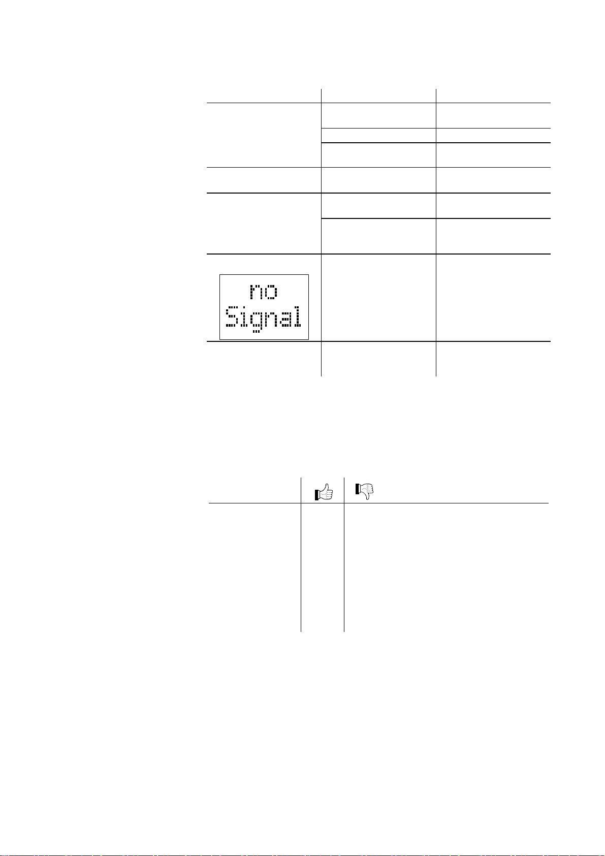
6.3 What to Do in Case of Problems
In the event of a fault or a complete failure of the output signal, the transmitter can
easily be checked.
Required tools / material
• Voltmeter / ohmmeter
• Allen key, size 2.5 mm
• Spare sensor (if the sensor is faulty)
Troubleshooting
The output signal is available at the sensor cable connector (Pin 2 and Pin 12).
In case of an error, it may be helpful to just turn off the mains supply and
turn it on again after 5 s.
GA09420_002_C0 – (2016-10) –
Leybold
39
Page 40
Maintenance, Repair
Problem Possible cause Correction
Output signal
permanently ≈0V
No supply voltage Turn on the power supply
transmitter in an unde-
Output signal ≈0.3 V
Display: "FAIL 8"
Output signal ≈0.5 V
Display: "FAIL 9"
Electronics unit not
Display: Internal data connection
Sensor cable defective or
not correctly connected
fined status
Hot cathode error
(sensor faulty)
Pirani error
(sensor defective)
mounted correctly on
sensor
not working
Check the sensor cable
Turn the transmitter off
and on again (reset)
Replace the sensor
(→ 41)
Replace the sensor
(→ 41)
Check the connection the
electronics unit - sensor
Turn the transmitter off
and on again after 5 s
Replace the electronics
unit
transmitter does not
switch over to BA at low
Pirani zero point out of
tolerance
Carry out a zero point
adjustment (→ 39)
pressures
Troubleshooting (sensor)
If the cause of a fault is suspected to be in the sensor, the following checks can be
made with an ohmmeter (the vacuum system need not be vented for this purpose).
Separate the sensor from the electronics unit (→ 14). Using an ohmmeter, make
the following measurements.
Ohmmeter measure-
ment between pins
2 + 4
4 + 5
6 + 7
4 + 1
6 + 1
3 + 1
9 + 1
6 + 3
9 + 3
≈37 Ω >>37 Ω
≈37 Ω >>37 Ω
≈0.15 Ω >>0.15 Ω
∞ << ∞
∞ <<
∞ <<
∞ <<
∞ <<
∞ <<
Possible cause
Pirani element 1 broken
Pirani element 2 broken
Filament of hot cathode broken
Electrode - short circuit to ground
Electrode - short circuit to ground
∞
Electrode - short circuit to ground
∞
Electrode - short circuit to ground
∞
Short circuit between electrodes
∞
Short circuit between electrodes
∞
GA09420_002_C0 – (2016-10) –
40
Leybold
Page 41
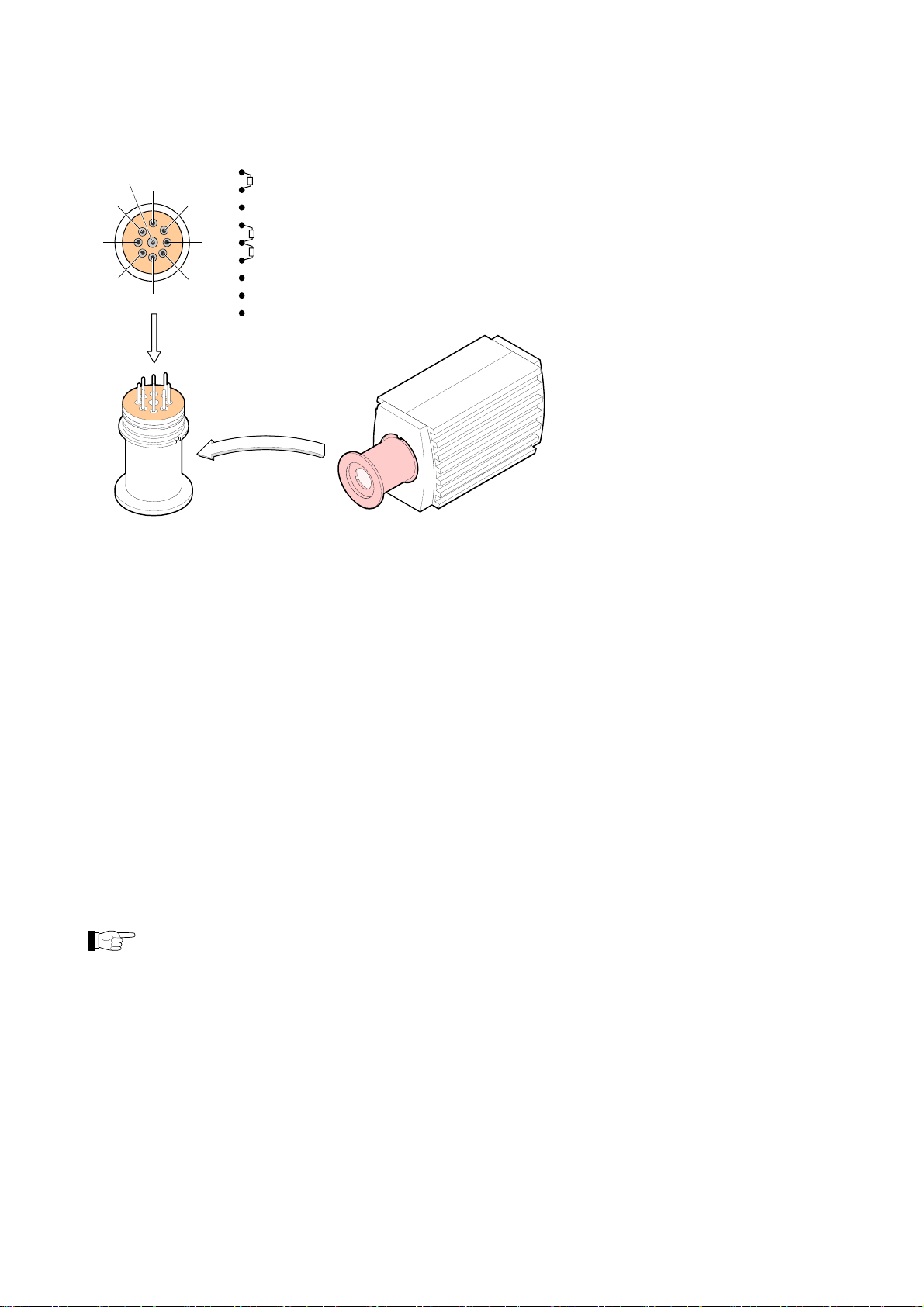
View on sensor pins
9
1
8
7
6
2
4
5
Maintenance, Repair
6
Hot cathode ca. 0.15 Ohm
7
8
Not connected
2
3
Pirani sensor 1 ca. 37 Ohm
4
Pirani sensor 2 ca. 37 Ohm
5
3
Anode
1
GND (connected to sensor housing)
9
Ion collector
Correction
All of the above faults can only be remedied by replacing the sensor (→ 41).
Troubleshooting on Fieldbus Transmitters (ITR 90 P)
Error diagnosis of fieldbus transmitters can only be performed as described above
for the basic sensor and sensor electronics. Diagnosis of the fieldbus interface can
only be done via the superset bus controller (→ [3]).
6.4 Replacing the Sensor
Replacement is necessary, when
• the sensor is severely contaminated
• the sensor is mechanically deformed
• the sensor is faulty, e.g. filament of hot cathode broken (→ 39)
• the sensor is faulty, e.g. Pirani element broken (→ 39)
Transmitter failures due to contamination or wear and tear as well as
expendable parts (filaments) are not covered by the warranty.
Required tools / material
• Allen key, size 2.5 mm
• Spare sensor (→ 43)
Procedure
Deinstall the transmitter (→ 36).
GA09420_002_C0 – (2016-10) –
Leybold
41
Page 42

Maintenance, Repair
Deinstall the electronics unit from the faulty sensor and mount it to the new
sensor (→ 14).
Adjust the transmitter (→ 37).
The new sensor is now installed.
GA09420_002_C0 – (2016-10) –
42
Leybold
Page 43
Options, Spare Parts, Storage
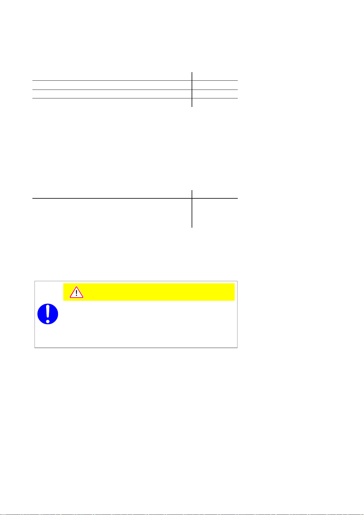
7 Options
Part number
24 VDC power supply / RS232C line (→ 23)
Bake-out extension 100 mm 127 06
Baffle DN 25 ISO-KF / DN 40 CF-R (→ 15)
8 Spare Parts
When ordering spare parts, always indicate:
• All information on the product nameplate
• Description and part number
Part number
Replacement sensor IE 90, vacuum connection DN 25 ISO-KF
(including Allen key)
Replacement sensor IE 90, vacuum connection DN 40 CF-R
(including Allen key)
9 Storage
121 06
121 07
E 121 02
E 121 03
Caution: vacuum component
Inappropriate storage leads to an increase of the desorption rate
and/or may result in mechanical damage of the product.
Cover the vacuum ports of the product with protective lids or grease
free aluminum foil. Do not exceed the admissible storage temperature
range (→ 10).
Caution
GA09420_002_C0 – (2016-10) –
Leybold
43
Page 44
Returning the Product, Disposal
10 Returning the Product
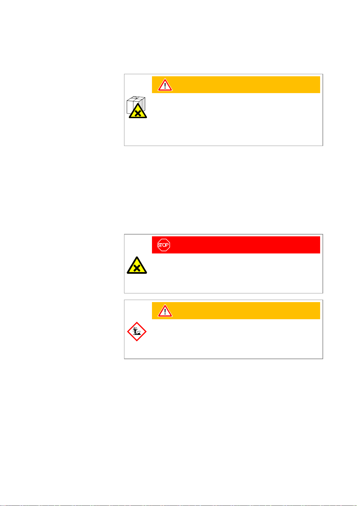
WARNING
WARNING: forwarding contaminated products
Contaminated products (e.g. radioactive, toxic, caustic or biological
hazard) can be detrimental to health and environment.
Products returned to Leybold should preferably be free of harmful
substances. Adhere to the forwarding regulations of all involved
countries and forwarding companies and enclose a duly completed
Products that are not clearly declared as "free of harmful substances" are decontaminated at the expense of the customer.
Products not accompanied by a duly completed declaration of contamination are
returned to the sender at his own expense.
11 Disposal
declaration of contamination (→ 49).
DANGER
DANGER: contaminated parts
Contaminated parts can be detrimental to health and environment.
Before beginning to work, find out whether any parts are contaminated. Adhere to the relevant regulations and take the necessary precautions when handling contaminated parts.
WARNING
WARNING: substances detrimental to the environment
Products or parts thereof (mechanical and electric components, operating fluids etc.) can be detrimental to the environment.
Dispose of such substances in accordance with the relevant local
Separating the components
After disassembling the product, separate its components according to the following criteria:
Contaminated components
regulations.
GA09420_002_C0 – (2016-10) –
44
Contaminated components (radioactive, toxic, caustic or biological hazard etc.)
must be decontaminated in accordance with the relevant national regulations,
separated according to their materials, and disposed of.
Other components
Such components must be separated according to their materials and recycled.
Leybold
Page 45

Appendix
A: Relationship Output Signal – Pressure
Conversion formulae
(U - 7.75) / 0.75 + c
p = 10
U = 0.75 × (log p - c) + 7.75
where U p c
[V] [mbar] 0
[V] [Pa] 2
[V] [Torr] -0.125
Conversion curve
Appendix
1E+04
1E+03
1E+02
1E+01
1E+00
1E–01
1E–02
1E–03
1E–04
1E–05
1E–06
1E–07
1E–08
1E–09
1E–10
Sensor error
Inadmissible range
1.0 2.0 3.0 4.0 5.0 6.0 7.0 8.0 9.0 10.0
0.0
Measuring signal U[V]
Inadmissible range
GA09420_002_C0 – (2016-10) –
Leybold
45
Page 46
Appendix
–
–
–
Conversion table
Output signal U
[V]
0.3 / 0.5
[mbar]
Pressure p
[Torr]
Sensor error (→ 39)
[Pa]
0.51 … 0.774 Inadmissible range
0.774 5×10
-10
3.75×10
1.00 1×10⁻⁹ 7.5×10
-10
5×10⁻⁸
-10
1×10⁻⁷
1.75 1×10⁻⁸ 7.5×10⁻⁹ 1×10⁻⁶
2.5 1×10⁻⁷ 7.5×10⁻⁸ 1×10⁻⁵
3.25 1×10⁻⁶ 7.5×10⁻⁷ 1×10⁻⁴
4.00 1×10⁻⁵ 7.5×10⁻⁶ 1×10⁻³
4.75 1×10⁻⁴ 7.5×10⁻⁵ 1×10⁻²
5.50 1×10⁻³ 7.5×10⁻⁴ 1×10⁻¹
6.25 1×10⁻² 7.5×10⁻³ 1×100
7.00 1×10⁻¹ 7.5×10⁻² 1×101
7.75 1×100 7.5×10⁻¹ 1×10²
8.50 1×101 7.5×100 1×10³
9.25 1×10² 7.5×101 1×10⁴
10.00 1×10³ 7.5×10² 1×10⁵
>10.00 Inadmissible range
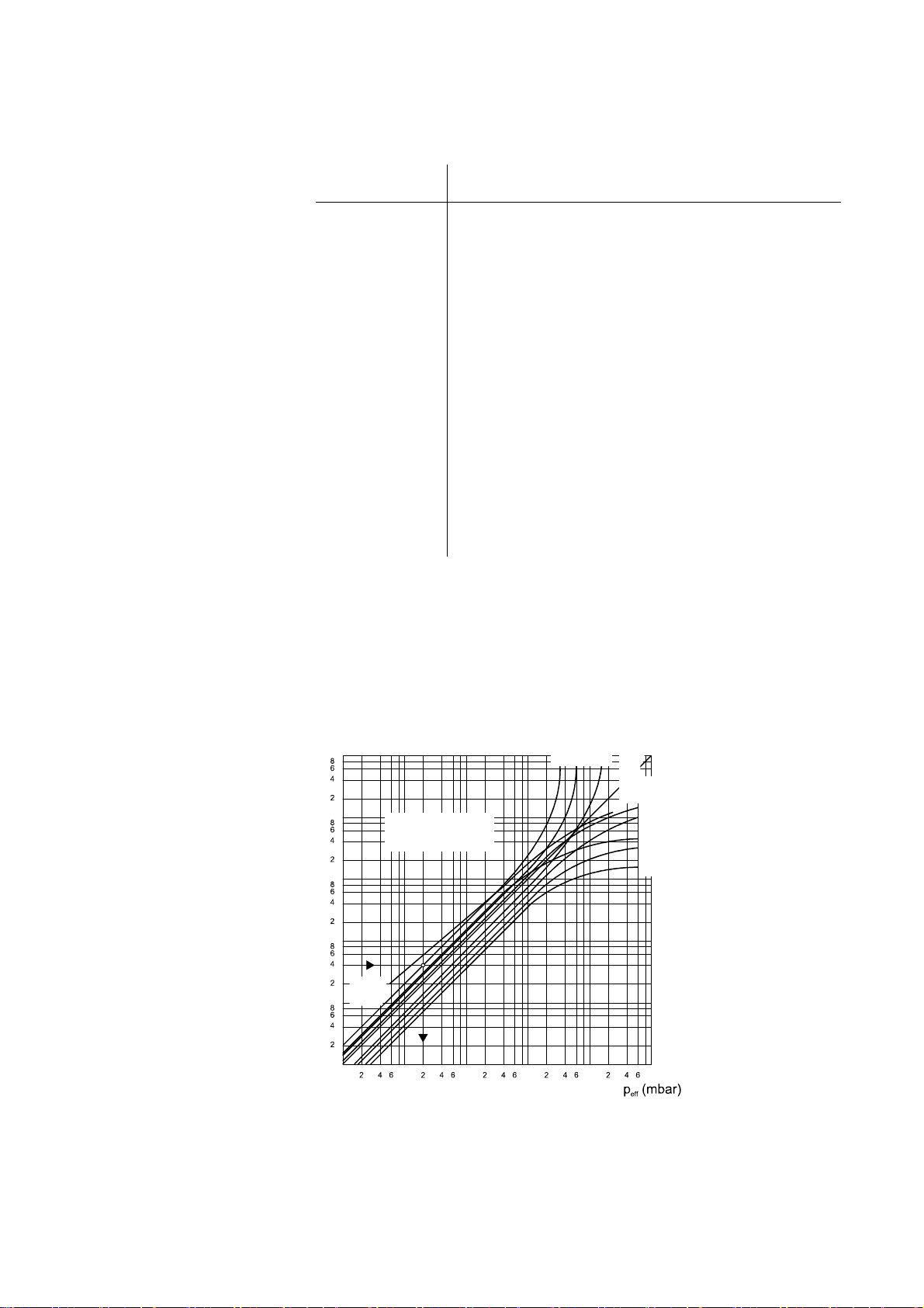
B: Gas Type Dependence
Indication range above 10-2 mbar
Pressure indicated (transmitter adjusted for air, Pirani-only mode)
p (mbar)
2
10
1
10
0
10
–1
10
–2
10
–3
10
10
Indication range
above 10 mbar)
HO
2
vapor
3
-2
2
10
1
10
10
H2He Ne
0
Air
O2
CO
N2
CO
2
Ar
Freon 12
Kr
Xe
1
10
2
10
GA09420_002_C0 – (2016-10) –
46
Leybold
Page 47
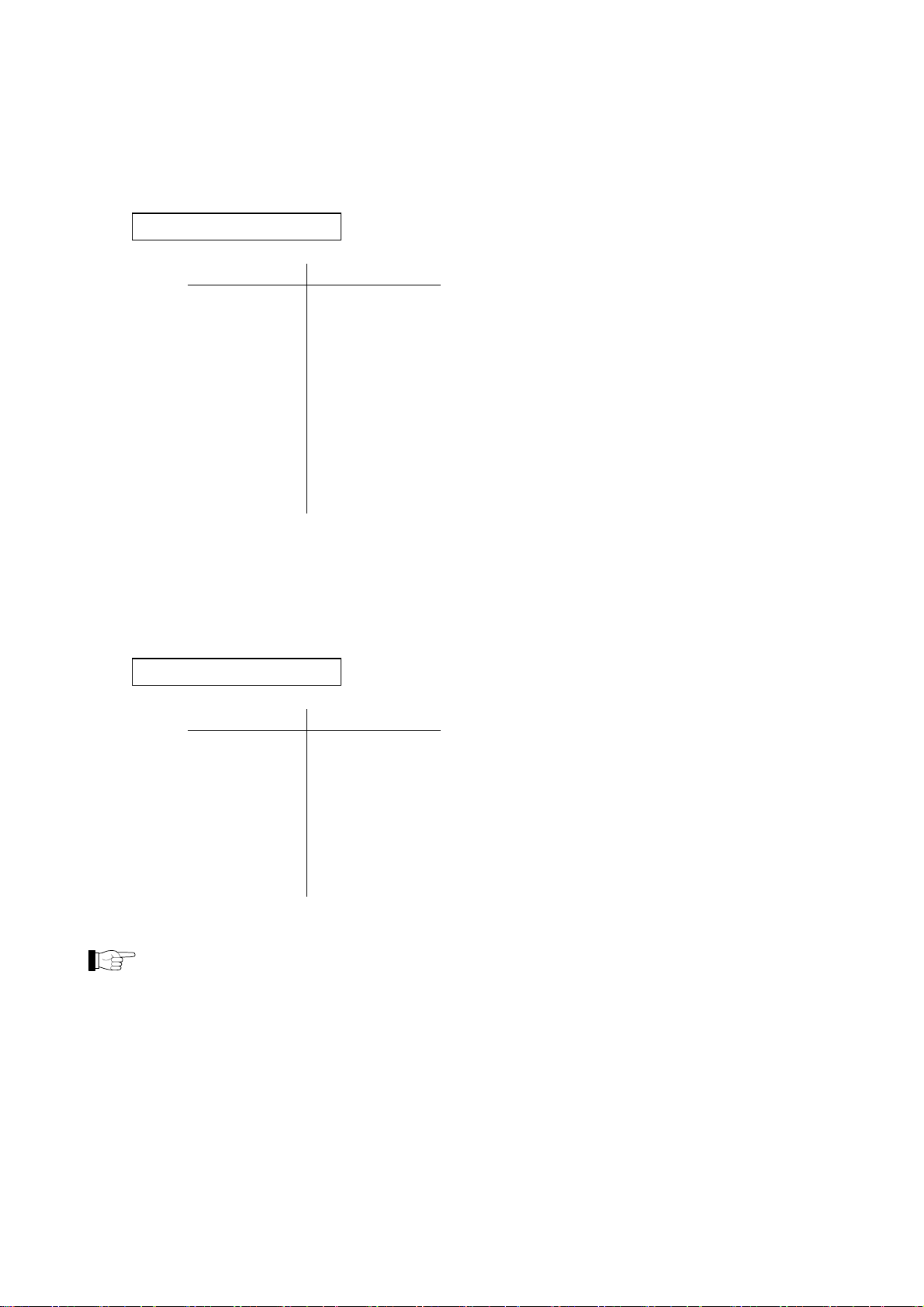
Calibration in pressure range 10-2 … 1 mbar
The gas type dependence in the pressure range 10-2 … 1 mbar can be compensated by means of the following formula:
p
= C × indicated pressure
eff
where Gas type Calibration factor C
Air, O2, CO 1.0
N
0.9
2
CO2 0.5
Water vapor 0.7
Freon 12 1.0
H
0.5
2
He 0.8
Ne 1.4
Ar 1.7
Kr 2.4
Xe 3.0
(The above calibration factors are mean values)
Calibration in pressure range <10-3 mbar
-3
The gas type dependence in the pressure range <10
mbar can be compensated
by means of the following formula (transmitter adjusted for air):
p
= C × indicated pressure
eff
where Gas type Calibration factor C
Air, O2, CO, N2 1.0
N
1.0
2
He 5.9
Ne 4.1
H
2.4
2
Ar 0.8
Kr 0.5
Xe 0.4
(The above calibration factors are mean values)
Appendix
A mixture of gases and vapors is often involved. In this case, accurate
determination is only possible with a partial-pressure measuring instrument.
GA09420_002_C0 – (2016-10) –
Leybold
47
Page 48

Appendix
C: Literature
[1] www.leybold.com
Instruction Sheet
IONIVAC ITR 90
KA09420_002
Leybold GmbH, D–50968 Köln
[2] www.leybold.com
Instruction Sheet
IONIVAC ITR 90 P
KA09421_002
Leybold GmbH, D–50968 Köln
[3] www.leybold.com
Interface Manual
Profibus ITR 90 P
SB09421_002
Leybold GmbH, D–50968 Köln
[4] www.profibus.com
(Profibus user organization)
[5] European Standard for Profibus EN 50170
[6] www.leybold.com
Leybold GmbH, D–50968 Köln
GA09420_002_C0 – (2016-10) –
48
Leybold
Page 49
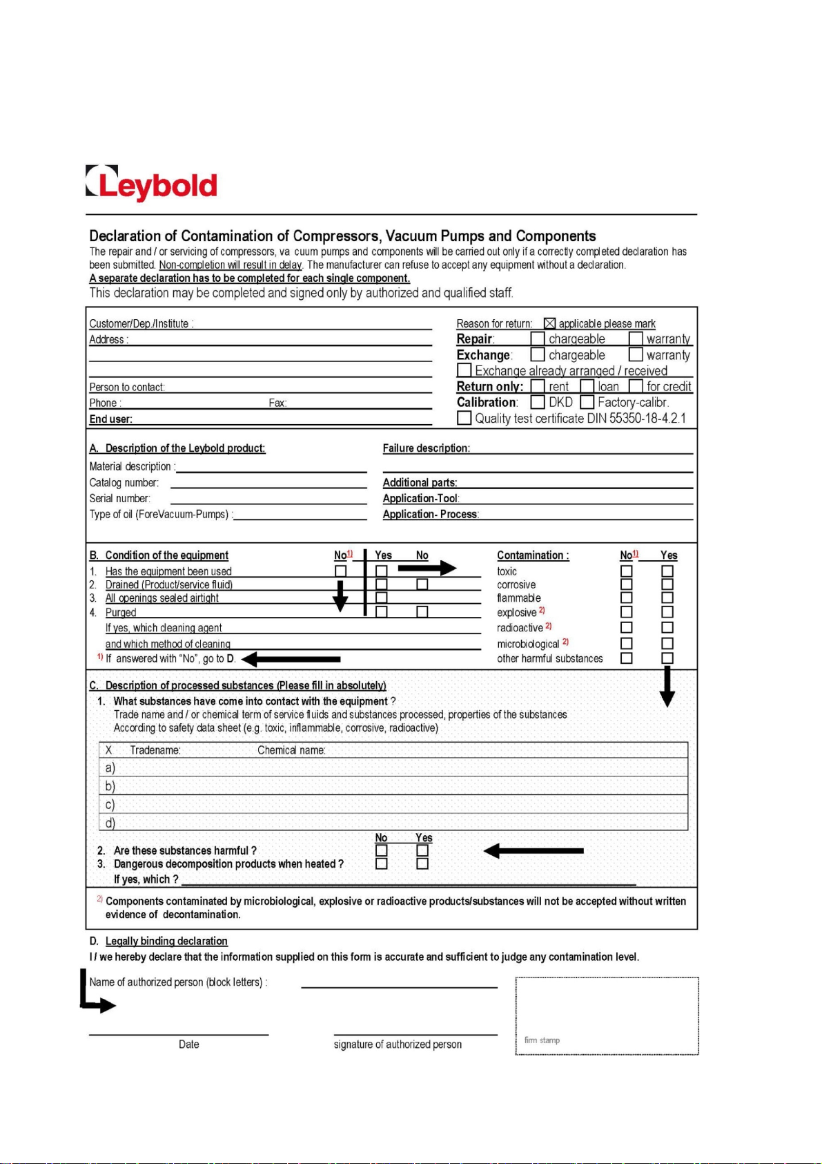
Declaration of Contamination
Declaration of Contamination
GA09420_002_C0 – (2016-10) –
Leybold
49
Page 50

Sales and Service
Germany
Leybold GmbH
Sales, Service, Support Center (3SC)
Bonner Strasse 498
D-50968 Cologne
T: +49-(0)221-347 1234
F: +49-(0)221-347 31234
[email protected]
www.leybold.com
Leybold GmbH
Sales Area North
Branch Office Berlin
Industriestrasse 10b
D-12359 Berlin
T: +49-(0)30-435 609 0
F: +49-(0)30-435 609 10
[email protected]
Leybold GmbH
Sales Office South
Branch Office Munich
Karl-Hammerschmidt-Strasse 34
D-85609 Aschheim-Dornach
T: +49-(0)89-357 33 9-10
F: +49-(0)89-357 33 9-33
[email protected]
[email protected]
Leybold Dresden GmbH
Service Competence Center
Zur Wetterwarte 50, Haus 304
D-01109 Dresden
Service:
T: +49-(0)351-88 55 00
F: +49-(0)351-88 55 041
[email protected]
Europe
Belgium
Leybold Nederland B.V.
Belgisch bijkantoor
Leuvensesteenweg 542-9A
B-1930 Zaventem
Sales:
T: +32-2-711 00 83
F: +32-2-720 83 38
[email protected]
Service:
T: +32-2-711 00 82
F: +32-2-720 83 38
[email protected]
France
Leybold France S.A.S.
Parc du Technopolis, Bâtiment Beta
3, Avenue du Canada
F-91940 Les Ulis cedex
Sales and Service:
T: +33-1-69 82 48 00
F: +33-1-69 07 57 38
[email protected]
[email protected]
Leybold France S.A.S
Valence Factory
640, Rue A. Bergès
B.P. 107
F-26501 Bourg-lès-Valence Cedex
T: +33-4-75 82 33 00
F: +33-4-75 82 92 69
[email protected]
Great Britain
Leybold UK LTD.
Unit 9
Silverglade Business Park
Leatherhead Road
Chessington
Surrey (London)
KT9 2QL
Sales:
T: +44-13-7273 7300
F: +44-13-7273 7301
[email protected]
Service:
T: +44-13-7273 7320
F: +44-13-7273 7303
[email protected]
Italy
Leybold Italia S.r.l.
Via Trasimeno 8
I-20128 Mailand
Sales:
T: +39-02-27 22 31
F: +39-02-27 20 96 41
[email protected]
Service:
T: +39-02-27 22 31
F: +39-02-27 22 32 17
[email protected]
Nederlands
Leybold Nederland B.V.
Floridadreef 102
NL-3565 AM Utrecht
Sales and Service:
T: +31-(30) 242 63 30
F: +31-(30) 242 63 31
[email protected]
[email protected]
Switzerland
Leybold Schweiz AG, Pfäffikon
Churerstrasse 120
CH-8808 Pfäffikon
Warehouse and shipping address:
Riedthofstrasse 214
CH-8105 Regensdorf
Sales:
T: +41-44-308 40 50
F: +41-44-302 43 73
[email protected]
Service:
T: +41-44-308 40 62
F: +41-44-308 40 60
[email protected]
Spain
Leybold Spain, S.A.
C/. Huelva, 7
E-08940 Cornellà de Llobregat
(Barcelona)
Sales:
T: +34-93-666 43 11
F: +34-93-666 43 70
[email protected]
Service:
T: +34-93-666 46 11
F: +34-93-685 43 70
[email protected]
America
USA
Leybold USA Inc.
5700 Mellon Road
USA-Export, PA 15632
T: +1-724-327-5700
F: +1-724-325-3577
[email protected]
Sales:
T: +1-724-327-5700
F: +1-724-333-1217
Service:
T: +1-724-327-5700
F: +1-724-325-3577
Brazil
Leybold do Brasil
Rod. Vice-Prefeito Hermenegildo Tonolli,
nº. 4413 - 6B
Distrito Industrial
Jundiaí - SP
CEP 13.212-315
Sales and Service:
T: +55 11 2152 0499
F: +55 11 99467 5934
[email protected]
[email protected]
Asia
P.R. China
Leybold (Tianjin)
International Trade Co. Ltd.
Beichen Economic
Development Area (BEDA),
No. 8 Western Shuangchen Road
Tianjin 300400
China
Sales and Service:
T: +86-22-2697 0808
F: +86-22-2697 4061
F: +86-22-2697 2017
[email protected]
[email protected]
India
Leybold India Pvt Ltd.
No. 82(P), 4th Phase
K.I.A.D.B. Plot
Bommasandra Industrial Area
Bangalore - 560 099
India
Sales and Service:
T: +91-80-2783 9925
F: +91-80-2783 9926
[email protected]
[email protected]
Japan
Leybold Japan Co., Ltd.
Headquarters
Shin-Yokohama A.K.Bldg., 4th floor
3-23-3, Shin-Yokohama
Kohoku-ku, Yokohama-shi
Kanawaga 222-0033
Japan
Sales:
T: +81 -45-471-3330
F: +81 -45-471-3323
[email protected]
Leybold Japan Co., Ltd.
Tsukuba Technical Service Center
1959, Kami-yokoba
Tsukuba-shi, Ibaraki-shi 305-0854
Japan
Service:
T: +81 -29-839 5480
F: +81 -29-839 5485
Malaysia
Leybold Malaysia
Leybold Singapore Pte Ltd.
No. 1 Jalan Hi-Tech 2/6
Kulim Hi-Tech Park
Kulim, Kedah Darul
Aman 09000
Malaysia
Sales and Service:
T: +604 4020 222
F: +604 4020 221
[email protected]
[email protected]
South Korea
Leybold Korea Ltd.
3F. Jellzone 2 Tower
Jeongja-dong 159-4
Bundang-gu Sungnam-si
Gyeonggi-do
Bundang 463-384, Korea
Sales:
T: +82-31 785 1367
F: +82-31 785 1359
[email protected]
Service:
623-7, Upsung-Dong
Cheonan-Si
Chungcheongnam-Do
Korea 330-290
T: +82-41 589 3035
F: +82-41 588 0166
[email protected]
Singapore
Leybold Singapore Pte Ltd.
8 Commonwealth Lane #01-01
Singapore 149555
Singapore
Sales und Service:
T: +65-6303 7030
F: +65-6773 0039
[email protected]
[email protected]
Taiwan
Leybold Taiwan Ltd.
No 416-1, Sec. 3
Chunghsin Rd., Chutung
Hsinchu County 310
Taiwan, R.O.C.
Sales and Service:
T: +886-3-500 1688
F: +886-3-583 3999
[email protected]
[email protected]
Original: German GA09420_001_C0 (2016-10)
ga09420. 002. c0
Headquarter
Leybold GmbH
Bonner Strasse 498
D-50968 Cologne
T: +49-(0)221-347-0
F: +49-(0)221-347-1250
[email protected]
www.leybold.com
 Loading...