

Page 1
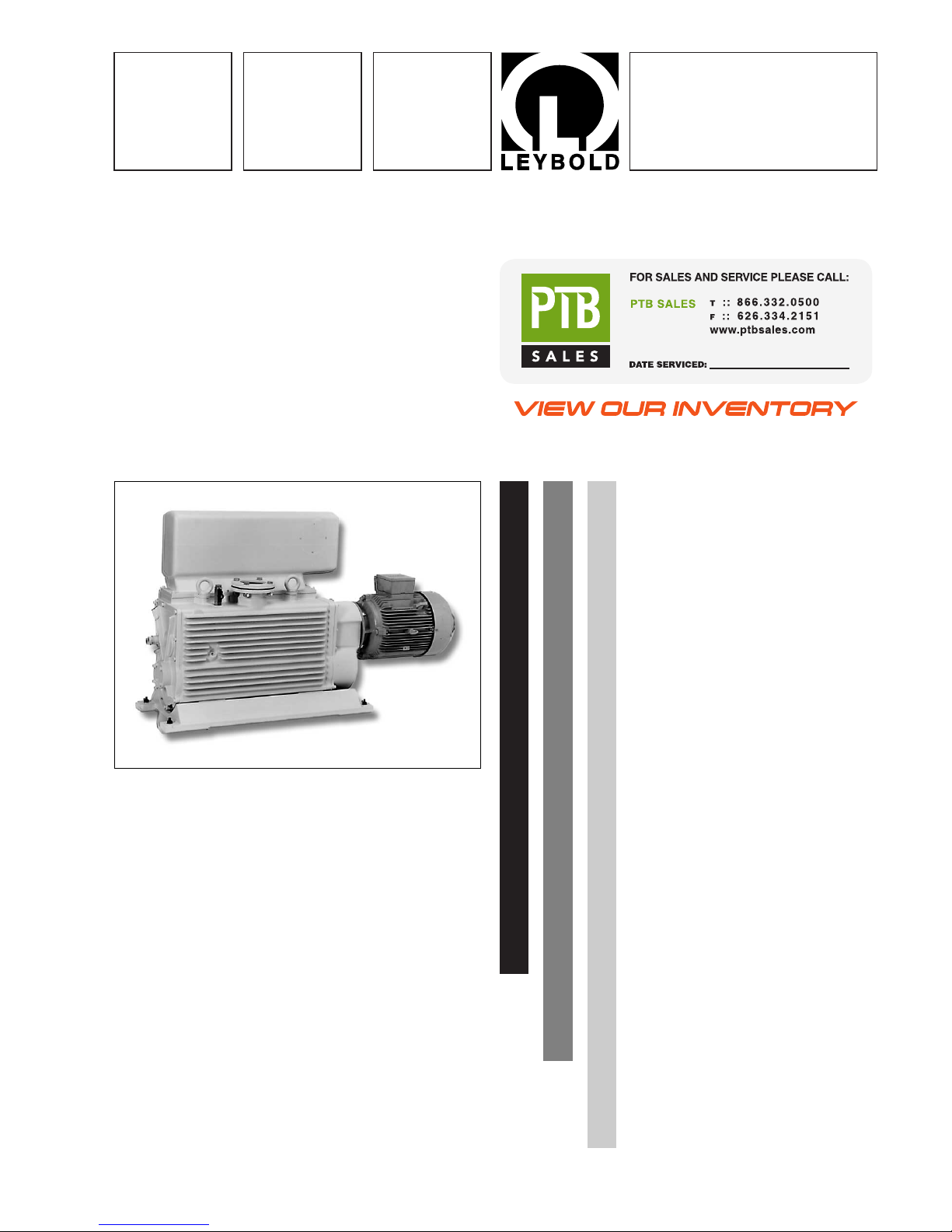
E and DK - Pumps
Rotary Piston Pumps
E 250, DK 200
Cat. No.
105 36
111 16
895 08
895 09
895 10
166 17
166 37
Operating Instructions
GA 02.200/8.02
Vacuum Solutions
Application Support
Service
LEYBOLD VACUUM
Page 2
GA 02.200/8.02 - 10/02
Contents
2
Contents
1 Description . . . . . . . . . . . . . . . . . . . . . . . . . .3
1.1 Design and Principle of Operation . . . . . . . . .3
1.1.1 Principle of Operation . . . . . . . . . . . . . . . . . .3
1.1.2 Design . . . . . . . . . . . . . . . . . . . . . . . . . . . . . .4
1.2 Supplied Equipment . . . . . . . . . . . . . . . . . . . .4
1.2.1 Transporting . . . . . . . . . . . . . . . . . . . . . . . . . .5
1.2.2 Shelving . . . . . . . . . . . . . . . . . . . . . . . . . . . .5
1.3 Technical Data and Accessories . . . . . . . . . . .6
1.4 Lubricants . . . . . . . . . . . . . . . . . . . . . . . . . . .7
2 Operation . . . . . . . . . . . . . . . . . . . . . . . . . . .8
2.1 Installation . . . . . . . . . . . . . . . . . . . . . . . . . . .8
2.2 Electrical Connections . . . . . . . . . . . . . . . . . .9
2.3 Connection to Vacuum System . . . . . . . . . . .10
2.3.1 Intake Side . . . . . . . . . . . . . . . . . . . . . . . . .10
2.3.2 Exhaust Side . . . . . . . . . . . . . . . . . . . . . . . .10
2.4 Start-up . . . . . . . . . . . . . . . . . . . . . . . . . . . .11
2.5 Operation . . . . . . . . . . . . . . . . . . . . . . . . . . .11
2.5.1 Pumping of Non-Condensable Gases . . . . . .11
2.5.2 Pumping of Condensable Gases and
Vapours . . . . . . . . . . . . . . . . . . . . . . . . . . . .11
2.6 Shutdown and Storage . . . . . . . . . . . . . . . . .12
2.7 Switching off through Monitoring Facilities . .12
3 Maintenance . . . . . . . . . . . . . . . . . . . . . . . .13
3.1 Maintenance Schedule . . . . . . . . . . . . . . . . .13
3.2 Checking the Condition of the Oil and the
Oil Level . . . . . . . . . . . . . . . . . . . . . . . . . . .14
3.3 Oil Change . . . . . . . . . . . . . . . . . . . . . . . . .15
3.3.1 Pumping Chamber . . . . . . . . . . . . . . . . . . . .15
3.3.2 Gear . . . . . . . . . . . . . . . . . . . . . . . . . . . . . .15
3.4 Cleaning the Dirt Trap . . . . . . . . . . . . . . . . .15
3.5 Cleaning the Pump . . . . . . . . . . . . . . . . . . .15
3.6 Disassembling and Reassembling the Pump 16
3.6.1 Preparations . . . . . . . . . . . . . . . . . . . . . . . .16
3.6.2 Disassembling the Valves and
Oil Level Glass . . . . . . . . . . . . . . . . . . . . . . .16
3.6.3 Disassembling the Motor End . . . . . . . . . . . .18
3.6.4 Disassembling the Front End . . . . . . . . . . . .20
3.6.5 Removing the Shaft and
Intermediate Plate(s) . . . . . . . . . . . . . . . . . .21
3.6.6 Cleaning the Parts and Checking for Wear . .22
3.6.7 Reassembling the Pump . . . . . . . . . . . . . . .22
3.7 Leybold Service . . . . . . . . . . . . . . . . . . . . .23
4 Troubleshooting . . . . . . . . . . . . . . . . . . . .24
EC Declaration of Conformity . . . . . . . . . .26
EEC Manufacturer’s Declaration . . . . . . . .27
Figures
The reference to diagrams, e. g. (1/2), consist of the Fig.
No.and Item No.in that order.
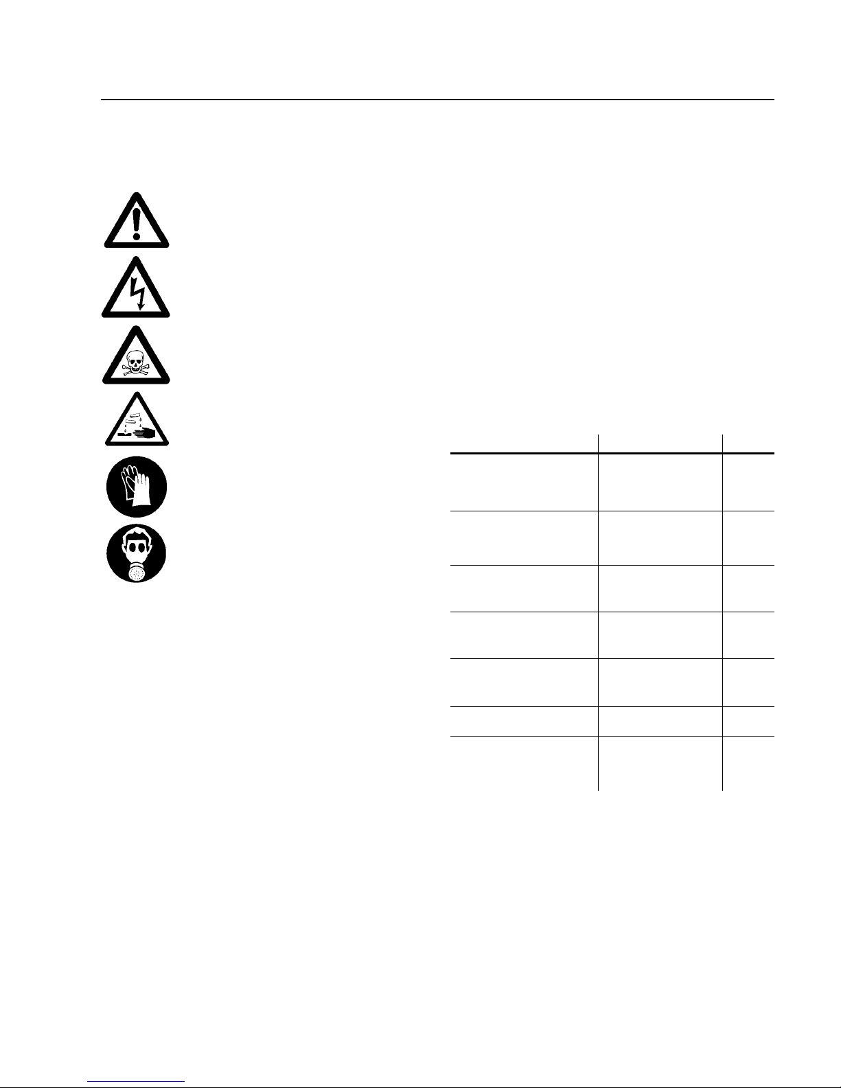
Indicates procedures that must be strictly
observed to prevent hazards to persons.
Indicates procedures that must strictly be
observed to prevent damage to, or destruction of the pump.
Leybold Service
If a pump is returned to LEYBOLD, indicate whether the
pump is free of substances damaging to health or
whether it is contaminated.
If it is contaminated also indicate the nature of the
hazard. LEYBOLD must return any pumps without a
“Declaration of Contamination“ to the sender’s address.
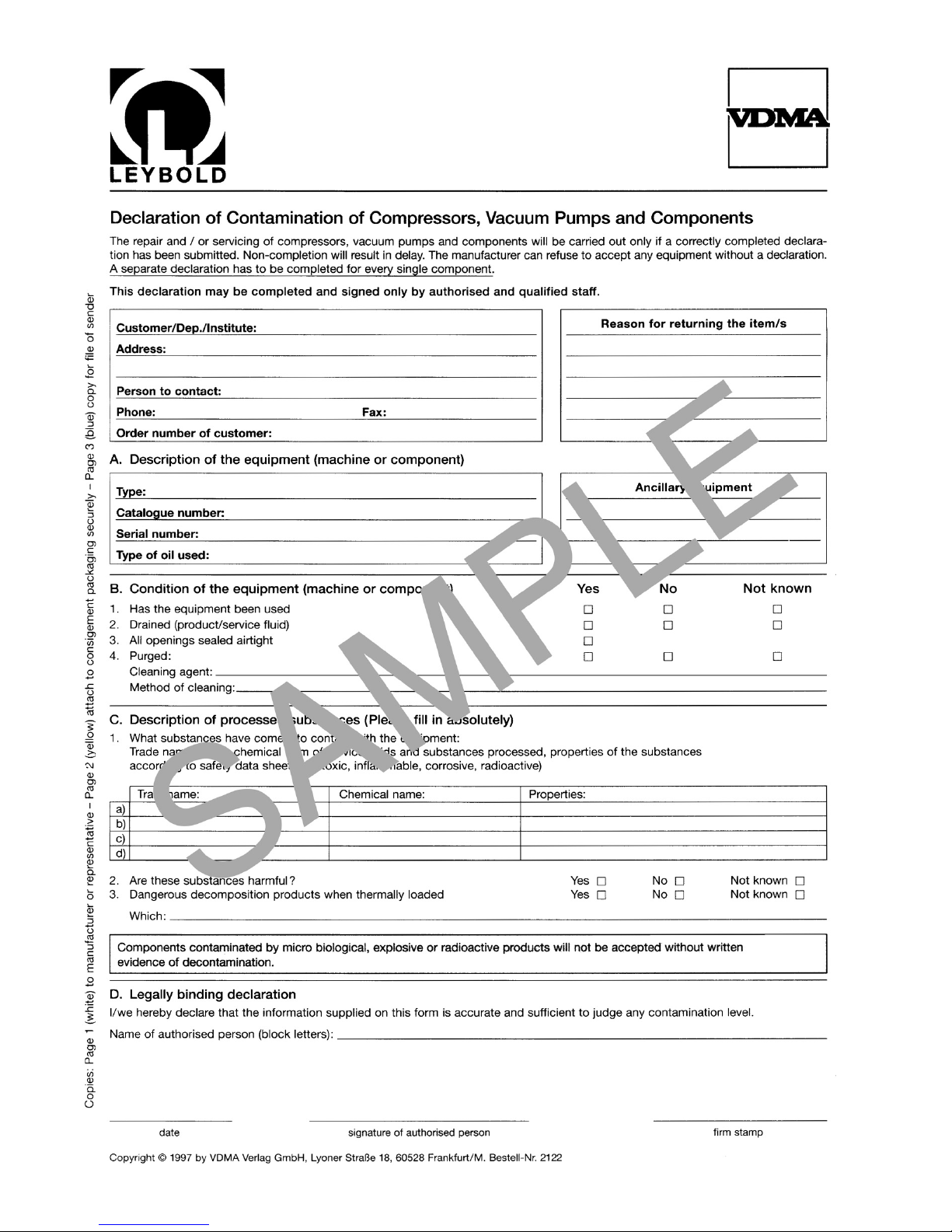
A sample of the required form has been reproduced at
the end of these Operating Instructions. A copy of the
actual form is included with each pump.
Disposal of Waste Oil
Owners of waste oil are entirely self-responsible for proper disposal of this waste.
Waste oil from vacuum pumps must not be mixed with
other substances or materials.
Waste oil from vacuum pumps (Leybold oils which are
based on mineral oils) which are subject to normal wear
and which are contaminated due to the influence of oxygen in the air, high temperatures or mechanical wear
must be disposed of through the locally available waste
oil disposal system.
Waste oil from vacuum pumps which is contaminated
with other substances must be marked and stored in
such a way that the type of contamination is apparent.
This waste must be disposed of as special waste.
European, national and regional regulations concerning
waste disposal need to be observed.Waste must only be
transported and disposed of by an approved waste disposal vendor.
The right of alterations in the design and the technical
data is reserved.The illustrations are not binding.
Warning
Caution
Page 3
GA 02.200/8.02 - 10/02
Description
3
1 Description
1.1 Design and Principle of
Operation
The E series comprises single-stage rotary piston
pumps, and the DK series consists of two-stage rotary
piston pumps. Their pumping capacity ranges from 200
to 250 m3· h-1.
E and DK series pumps can pump gases and vapours
and evacuate v essels or vacuum systems in the medium
vacuum range.Those of standard design are not suitable
for pumping higher than atmospheric concentrations of
oxygen or extremely aggressive or corrosive media.
1.1.1 Principle of Operation
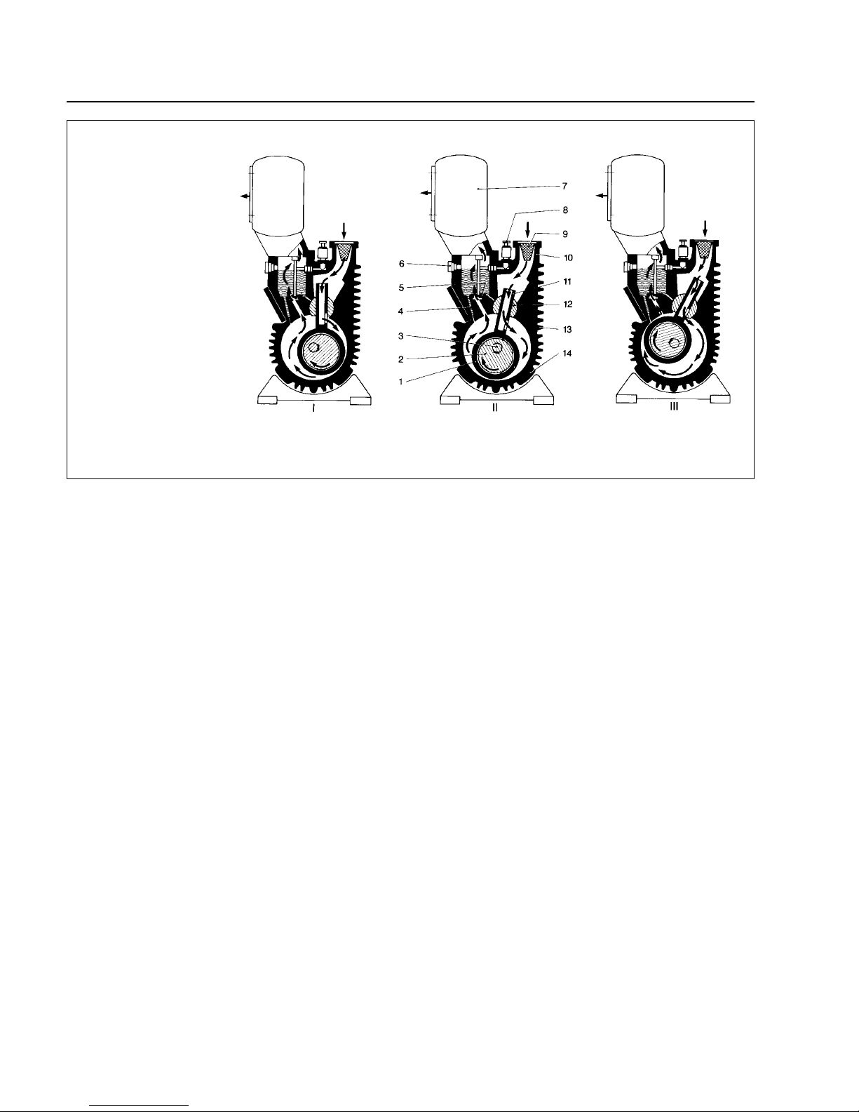
In the pump body (2/14), the piston (2/1) is guided by the
eccentrically mounted cam (2/2) along the wall of the
pumping chamber, without contacting it.The piston divides the chamber into two sections that change in size.
The piston has a hollow neck (2/11) with a slot on the
side.
The gas being pumped comes through the inlet port
(2/10) into the piston neck.
When the slot in the piston neck is opened by the slide
valve (2/12), the gas flows into the expanding section of
the pumping chamber (right-hand section in Fig. 2). The
gas is encapsulated in the pumping chamber, then compressed during the next revolution of the piston (left-hand
section in Fig. 2) and expelled at the exhaust valve (2/5).
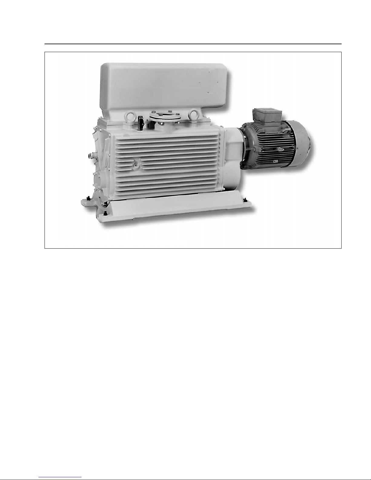
Fig. 1 Rotary Piston Pump E 250
Page 4
GA 02.200/8.02 - 10/02
1.1.2 Design
The E-250 has three pumping chambers operating in
parallel.
The DK-200 has three, pumping chambers operating in
series, with the larger chamber(s) on the intake side
acting as the first pump stage, and the smaller chamber
as the second pump stage.
Above the exhaust valves (2/5) is an oil reservoir, from
which oil is injected into the pumping chamber via oil
channels (2/4).
The oil is used for sealing, lubrication and cooling. Most
of the oil entrained with the compressed gas is mechanically trapped in the exhaust box (2/7). The oil cycle is
maintained by the difference between the pump's intake
pressure and atmospheric pressure.
The rotary piston pumps are driven by a directly flanged
motor.The pump's rotational speed is lower than that of
the motor; the pump shaft and motor are interlinked by a
toothed gear, which has its own oil reservoir.
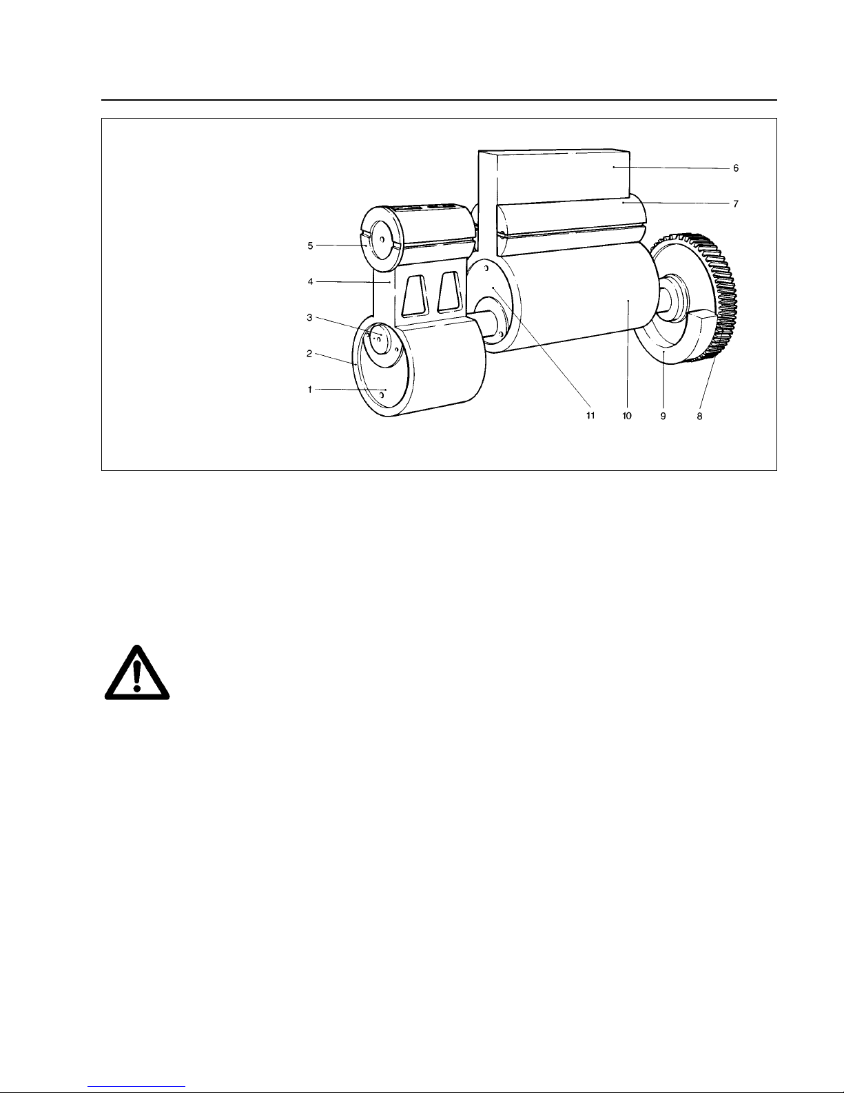
The cams (2/2) or (3/1) and (3/11) and a ring gear are
arranged on the pump shaft in such a way that the
eccentrically rotating array is dynamically balanced.
The pumps are air-cooled.The required air flow is generated by the attached motor. A built-in reverse lock prevents the motor turning the pump shaft in the wrong
direction.
All E and DK series pumps have a gas ballast device.
When the gas ballast valve (2/8) is open, a dosed quantity of air – so-called "gas ballast" – is admitted into the
pumping chamber.
Description
This prevents condensation of v apours in the pump up to
the vapour tolerance specified in the Technical Data.
In addition, a small amount of air is constantly admitted
via the silencer nozzles so as to avoid loud running of the
pump at ultimate pressure.
1.2 Supplied Equipment
The pumps are supplied with small-flange (KF) and/or
clamp-flange (ISO-K) connections (see Section 1.3 –
Technical Data).
For each small-flange connection, a centering ring and a
clamp ring are supplied. These connections are sealed
with a rubber diaphragm.
For each clamp-flange connection, a sealing disk with
collar flange and snap ring is supplied. These connections are sealed with cardboard disks.
The centering ring or sealing disk for the inlet flange contains a dirt trap.
The pump and gear housing are filled with N 62 oil.
4
Key to Fig. 2
1 Piston
2 Cam
3 Drive shaft
4 Oil channel
5 Exhaust valve
6 Oil-level glass
7 Exhaust box
8 Gas ballast activator
9 Dirt trap
10 Inlet port
11 Piston neck
12 Slide valve
13 Cooling fins
14 Pump body
Fig. 2 Cross-section of rotary piston pump and principle of operation
Page 5
GA 02.200/8.02 - 10/02
Description
1.2.1 Transporting
• Pumps which are filled with operating
agents must only be transported standing
upright. Otherwise oil may come out of the
pump.During transportation av oid any other
orientations.
• Check the pump for the possible presence
of oil leaks. There exists the danger that
someone may slip on spilt oil.
• In order to lift the pump only use the eyes
provided on the pump for this purpose and
only use the required type of lifting equipment (see Operating Instructions, 7/4).
Make sure that the lifting equipment has is safe to operate. Use only suitable lifting gear. Make sure that all
safety regulations are observed.
5
1.2.2 Shelving
• Before putting a pump into service once
more, store it at a dry place, preferably at
room temperature (20 °C). Before shelving
a pump disconnect it properly from the
vacuum system, purge it with dry nitrogen
and do an oil change.
All inlet and discharge openings on the
pump must be sealed with the shipping
seals supplied with the pump.
Set the gas ballast switch to the “OFF”position; if the pump is to be shelved for a longer period of time you should place it in a
PE bag containing some dessicant (silica
gel) and the firmly seal the bag.
When shelving the pump for over one year, you should
run maintenance on the pump and also do an oil change
before putting the pump into service again. We recommend that to get in touch with Leybold Service in such a
case.
Key to Fig. 3
1 Cam
2 Piston
3 Drive shaft
4 Piston neck
5 Slide valve
6 Piston neck
7 Slide valve
8 Ring gear
9 Counterbalance
10 Piston
11 Cam
Fig. 3 Counterbalancing of rotary piston pump
Caution
Caution
Warning
Page 6
Description
6
GA 02.200/8.02 - 10/02
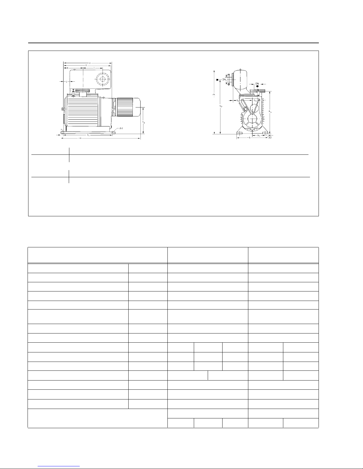
DN DN
1
a
1)
a
1
a
2
bb1b
2
b3ød
E 250/DK 200 63 ISO-K 63 ISO-K 1190 780 30 340 140 202
2)
52 14
DN DN
1
ef ghh1h
2
h
3
kl
E 250/DK 200 63 ISO-K 63 ISO-K 777 750 65 740 475 636 295 337 290
Fig. 4 Dimensional drawing
1)
Dimension “a” applies only in connection with the standard type of motor used by us
2)
Without adaptor
105 36 111 16895 08 895 09 895 10
1.3 Technical Data and Accessories
Rotary Piston Pump E 250 DK 200
Nominal pumping speed
1)
m3· h
-1
290
225
Intake port
Exhaust port
DN
DN
63 ISO-K
63 ISO-K
63 ISO-K
63 ISO-K
Pumping speed
1)
m3· h
-1
250 200
Ultimate total pressure with gas ballast
1)
mbar
< 5 · 10
-1
< 4 · 10
-3
Ultimate partial pres. without gas ballast
1)
mbar
< 4 · 10
-2
< 5 · 10
-4
Water vapour tolerance
mbar 60 26
Oil filling, pump chamber l
8 4
Oil filling, gear l
0,4 0,4
Motor power at 230/380 V +/- 10 % kW (Hz)
Motor power at 200-230 V/460 V +/- 10 % kW (Hz)
Motor power at 460 V +/- 10 % kW (Hz)
5.5 (50) 5.5 (50)- - -
- -- 5.5 (60) 5.5 (60)
-
-
5.5 (50)
-
-
Weight with motor and oil filling kg 375 375
Cat. Nos. 166 37 without motor* 166 17 without motor*
Nominal speed of the motor, 50 Hz rpm 1500 / 50 Hz
Nominal speed of the pump rpm 540 540
Motor protection IP 54 54
1730 / 60 Hz
1500 / 50 Hz
1730 / 60 Hz
*Requirement for the motor: Maximum motor speed must not exceed 1500 rpm, motor power must be at least 5 kW.
Page 7
GA 02.200/8.02 - 10/02
Description
7
1)
To DIN 28 400 and subsequent numbers
Accessories E 250 DK 200
Vibration absorbing feet 101 55 101 55
Seal kit 192 63 192 63
Dust separator 178 02 178 02
Dust filter 278 17 278 17
Separator (intake side) 188 45 188 45
Elbow DN 63 ISO-K
268 67 268 67
Drain tap (vacuum tight/oil tight) 190 90 190 90
Separator (exhaust side) 188 45 188 45
Exhaust filter 189 45 189 45
Exhaust filter box 189 47 189 47
SECUVAC valve 283 15 283 15
Oil level regulator 101 37 101 37
Mechanical oil filtering facility 101 31 101 31
-- Cat. Nos. --
Without gas ballast
With gas ballast
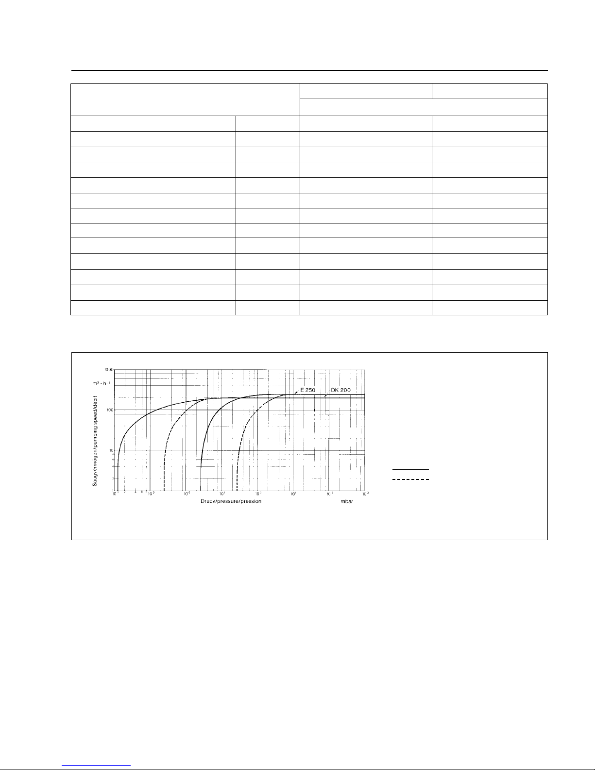
Fig. 5 Pumping speed characteristics
1.4 Lubricants
The same oil can be used for the pump and the gear.
The rotary piston pumps should be run with oil N 62. N
62 is a vacuum pump oil that meets many requirements:
• Low vapour pressure, even at high temperatures.
• Flat viscosity curve.
• Minimum water content and absorption.
• Good lubricating properties.
• Resistant to ageing under mechanical strain.
The use of other special-grade lubricants for specific
applications is possible.Please consult us in such cases.
Page 8
GA 02.200/8.02 - 10/02
Description
8
2.1 Installation
The standard pump is not suited for installation in explosion hazard areas.
• Before starting up the pump for the first
time make sure that the pump and the
installed accessories meet the requirements of your application and that safe operation is ensured. If hazardous substances
are to be pumped, ensure that all relevant
safety regulations are observed.
• Avoid exposure of any part of the human
body to a vacuum.The exists the danger of
injury. Never operate the pump with its
intake open.V acuum connections as well as
oil fill and oil drain openings must never be
opened during operation.
The safety regulations which apply to the
application in each case must be observed.
This applies to installation, operation and
maintenance (servicing) as well as waste
disposal and transport.
Our technical sales staff are at hand should you have
any questions in these matters.
Before pumping oxygen (or other highly
reactive gases) at concentrations exceeding the concentration in the atmosphere
(> 21 % for oxygen) it will be necessary to
use a special pump.Such a pump will have
to be modified and de-greased, and an inert
special lubricant (like PFPE) must be used.
The pump is not suited for processes and
pumping of:
1 - Explosive gases or vapours.
2 - Oxidants (except the Formblin types,
see Operating Instructions GA PFPE
07.009).
3 - Pyrophrous gases.
4 - The pumps are not suited for pumping
of liquids or very dusty media. Corresponding protection measures must be
introduced.
Our technical sales staff are at hand should you have
any questions in these matters.
Install the pump on a flat, horizontal surface.The base of
the pump must be supported evenly and horizontally at
the four points of contact. If the pump stands on a level
floor, it is not necessary to bolt it down unless the inlet
and exhaust lines are rigidly connected. Always bolt the
pump down when installing it in a frame or on a stand.
For this we recommend using our vibration absorbing
feet (see Accessories).
The use of vibration absorbing feet does not
prevent pump vibration, but merely reduces
the vibrations transmitted to the supporting
structure.
However, the inclination of the pump must
not exceed 10° from the vertical.
The pump's ambient temperature should be
between 12 °C and 40 °C. Lower temperatures necessitate additional measures
when starting the pump (pre-heating the oil,
larger motor); higher temperatures cause
greater wear of the pump and require more
frequent oil changes.
To permit adequate cooling of the pump
leave about 0.5 m (20 inches) space between the pump and the wall. Always keep
the air intakes at the motor fan clean.
Caution
2 Operation
Warning
Warning
Page 9
GA 02.200/8.02 - 10/02
Operation
9
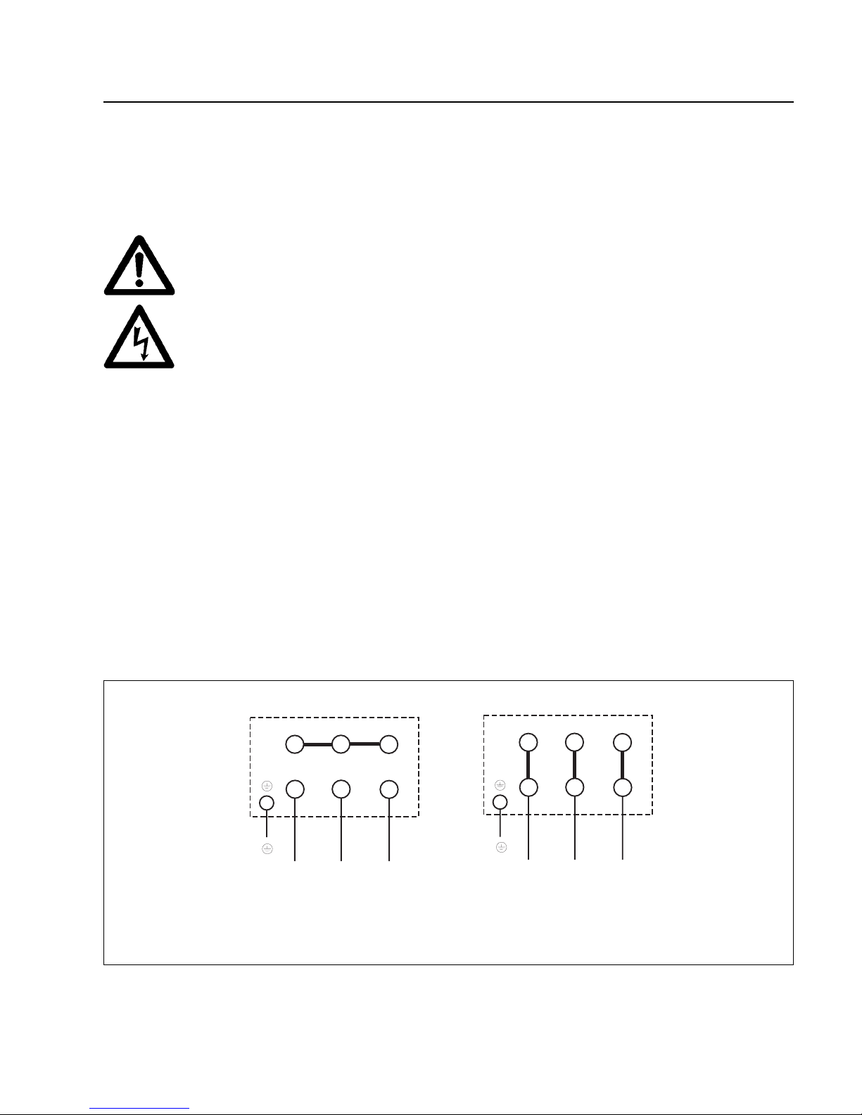
2.2 Electrical Connections
For all work on the wiring, disconnect the
line cords from the mains.
The electrical connections must only be
provided by a trained electrician in accordance with the regulations of the IEC 64
international series of standards.
Connect the pump's motor to the correct supply voltage
via the terminals in the junction box.
Only the PG fittings provided on the junction
box may be used.
For proper connection, a suitable motor protection s witch
must be used.
Set the switch in accordance with the rating on the motor
nameplate.
After connecting the motor and every time
you alter the wiring, check the direction of
rotation (see marking on motor hood).
When connecting a condenser to the E 250
and DK pumps - without motor - it must be
ensured under all circumstances that a
speed of 1500 rpm is not exceeded and that
at least 5 kW of motor power is available.
When checking the direction of rotation, the inlet and
exhaust ports must be open. Switch on the motor briefly
and then switch it off immediately.If the reverse lock prevents the pump from starting, disconnect the line cords
from the mains and interchange two of the input leads at
the motor junction box.
For checking the direction of rotation it is advisable to
use a phase-sequence indicator.
If the pump has a built-in SECUVAC valve, connect it so
that it closes when the pump is not running.
Warning
Caution
Fig. 6 Electrical connections
W 2
U 2
V 2
U 1
V 1
W 1
L 1
L 2 L 3
L 1
L 2 L 3
W 2
U 2
V 2
U 1
V 1 W 1
Y - Star connection
∆ - Delta connection
Caution
Page 10
GA 02.200/8.02 - 10/02
Operation
10
2.3 Connection to Vacuum
System
(see Fig. 7)
If you have not already done so, remove the temporary
covers from the inlet and exhaust ports.
Use flexible metal bellows to connect the intake and
exhaust lines without straining them.
The lines and the sealing surfaces of the flange connec-
tions must be clean.
When pumping vapours, it is advisable to insert conden-
sate traps on the intake and exhaust sides (see Section
1.3).
2.3.1 Intake Side
The cross-section of the intake line should be at least the
same as that of the inlet port. If the intake line is too narrow, it reduces the pumping speed.
If the medium pumped contains dust, a dust filter should
be installed upstream of the pump in addition to the dirt
trap supplied.
We strongly recommend installing a SECUVAC valve
between the vacuum system and the inlet port. This
valve closes automatically when the pump is not running
and thus protects the vacuum system against the entry
of air and oil from the pump. The valve simultaneously
vents the pump when it is not running.
2.3.2 Exhaust Side
The exhaust gases must be lead aw a y saf ely and - if required - subjected to suitable
post-processing.
To prevent the room in which the pump is located from
being contaminated by oil mist or the medium pumped,
we strongly advise you to connect an exhaust line. This
is always needed if the exhaust gas is noxious.
Depending on the application of the pump
and the medium pumped, please observe
the relevant safety rules and specifications.
To remove oil mist from the pump's exhaust gas, it is
recommended to install an exhaust filter or to replace the
exhaust box by an exhaust filter box (AFK 1 / AFK 2, see
Accessories).
The cross-section of the exhaust line should be at least
the same as that of the pump's exhaust port. If the
exhaust line is too narrow, excessive pressures may
build up in the pump.
Install the exhaust line with a downward slope so as to
prevent condensate flowing back into the pump.If this is
not possible, insertion of a condensate trap is strongly
recommended (see Section 1.3).
If several pumps are connected to a common exhaust
line, ensure an adequate cross-section and a non-return
valve at the exhaust of each pump.
In order to avoid an inadmissible excess
pressure in the exhaust line we generally
recommend installing an overpressure protection facility when starting up the pump for
the first time.
You can install either an excess pressure valve or a bursting disk (response pressure p < 1500 mbar, abs.).The
corresponding safety device must be installed in a such
a way to prevent any damages to property or persons.
On no account may the pump be operated with a bloc ked
or restricted exhaust line.Make sure before start-up that
any blinds or similar shut-off devices in the exhaust line
on the pressure side are opened and that the exhaust
lines are not obstructed by deposits.
Warning
Warning
Warning
Page 11
GA 02.200/8.02 - 10/02
Operation
11
The pressure in the exhaust line must be greater than
500 mbar (abs.) so that the pressure differential (in relation to the pumping chamber) needed for lubrication is
maintained. It must, however, remain below 1300 mbar
(abs.) during operation to avoid damage to the seals of
the pump.
2.4 Start-up
The pumps are supplied with the necessary oil charge in
ready-to-use condition.
The oil level of the pump can only be checked properly
when the pump is running. It must then be in the middle
of the oil-level sight glass (7/3).
The pump is designed for perfect start-up at temperatures over 12 °C as per PNEUROP.
Each time after switching the pump on, the
oil level must be checked.
2.5 Operation
Rotary piston pumps can attain surface
temperatures in excess of 80 °C.There thus
exists the danger of receiving burns.
Note the warnings as to potential dangers given on the
pump.
The rotary piston pumps can pump gases and vapours.
To pump vapours, the gas ballast valve must be open
and the pump must have reached its operating temperature.
2.5.1 Pumping of Non-Condensable Gases
If the pump system contains mainly permanent gases,
the pump can be operated without gas ballast, provided
that the saturation vapour pressure at operating temperature is not exceeded during compression.
If the composition of the gases to be pumped is not
known and if condensation in the pump cannot be ruled
out, we recommend that the pump be operated pursuant
to Section 2.5.2 with the gas ballast valve open.
2.5.2 Pumping of Condensable Gases and
Vapours
With the gas ballast valve open and at operating temperature (approx. 70 °C - 95 °C), the rotary piston pump
can pump pure water vapour up to the values indicated
in the Technical Data.
The gas ballast valve is opened manually (7/2).The running noise of the pump is slightly louder if the gas ballast
valve is open.
When vapours are pumped, ensure that the pump has
run up for approx.15 min.with closed intake line and with
gas ballast.
Only when the pump has attained its operating temperature can vapour be pumped off
up to the permissible limit .
One sign of condensation of vapours in the pump is a
rise in the oil level during operation of the pump. At the
same time the oil gets turbid, for example by the uptake
of water.
When vapours are pumped, the pump must not be switched off immediately upon completion of the process
because the condensate dissolved in the pump oil may
cause corrosion.T o pre v ent this , the pump must continue
to operate with open gas ballast valve and closed intake
line until the oil is free of condensate. It is advisable to
allow the pump to operate in this mode for at least 30
min. after completion of the process.
When pumping vapours do not use an AFK
1/2. It is better to use an external AF 100-
250.
In cycle operation, the pump should not be
switched off during the intervals between
the individual working phases, but should
continue to run (with low power consumption at ultimate pressure) with gas ballast
valve open and inlet port closed (if possible
via a valve).
Once all vapours have been pumped off from a process
(e. g. during dr ying), the gas ballast valve can be closed
in order to improve the attainable ultimate pressure.
Caution
Warning
Warning
Caution
Caution
Page 12
GA 02.200/8.02 - 10/02
Operation
12
2.6 Shutdown and Storage
• When the pump has been switched off
while warm, it may not be switched on
immediately again.
• If the pump has been pumping hazardous
substances you must make sure that all
relevant safety regulations are observed
before opening the intake or exhaust flanges.
This applies equally to opening of the oil fill
and oil drain plugs.
If required wear suitable protective clothing.
To shut down the pump, disconnect it from the vacuum
system using a valve.If vapours or aggressive/corrosive
media are pumped, let the pump run for at least another
30 min. with the gas ballast valve open. Then shut it
down. The pump is automatically vented within 2 to 5
min.
When using the pump in processes with aggressive or
corrosive media, it is advisable to let the pump continue
to operate even during long non-working intervals (e. g.
overnight) with the intake line closed and the gas ballast
valve open.This avoids corrosion when the pump is not
running.
If the pump is to be shut down for a prolonged period
after having been used to pump aggressive or corrosive
media, or if it is to be stored, proceed as follows:
If hazardous substances were pumped,
take suitable precautions.
Drain the oil (see Section 3.3).
Fill the pump with fresh oil (see Section 3.3) and let it run
for a while.
Drain the oil again and fill the pump with fresh oil once
more (see Section 3.3).
Seal the connecting ports. Special preservation or slus-
hing oils need not be used.
2.7 Switching off through
Monitoring Facilities
When the pump has been switched off
while warm by a motor protection switch, for
example, you may only switch the pump on
again manually after it has cooled down and
after having removed the cause for the
shut-down.
• When the pump has been switched off
while warm, it may not be switched on
immediately again.
• If the pump has been pumping hazardous
substances you must make sure that all
relevant safety regulations are observed
before opening the intake or exhaust flanges.
This applies equally to opening of the oil fill
and oil drain plugs.
If required wear suitable protective clothing.
Warning
Warning
Warning
Page 13
GA 02.200/8.02 - 10/02
Maintenance
13
3 Maintenance
Disconnect the electrical connections for all
disassembly work on the pump.Make absolutely sure that the pump cannot be accidentally started.
If the pump was used for hazardous substances, determine the type of hazard first
and take suitable precautions.
Before beginning with any maintenance
work you must decontaminate the pump
first.
Observe all relevant safety regulations!
Never exchange the oil or the filters while
the pump is still warm. Wear suitable protective clothing.
When disposing of used oil, please observe
the applicable environmental protection
regulations!
If you send a pump to Leybold for repair,
please specify all hazardous substances in
or around the pump.Please use the special
form for this which has been included with
these Operating Instructions.
Due to their design, the rotary piston pumps normally
require very little maintenance. The necessar y work is
described in the sections below.
All work on the pump must be carried out by suitably trained personnel.Maintenance or repairs done by inexperienced personnel may affect the life and performance of
the pump and may cause problems when filing warranty
claims.
LV has practical courses on the maintenance, repair and
troubleshooting of rotary piston pumps. Further details
are available from LV upon request.
If the pump is employed in highly contaminated ambient air, make sure that its air
cooling and the gas ballast facility are not
impaired.
If the pump has been used for corrosive
media, we recommend that any maintenance work be carried out immediately so
as to avoid corrosion.
Treat all sealing surfaces of the pump with
the utmost care.
3.1 Maintenance Schedule
The intervals stated in the maintenance schedule are
approximate values for normal pump operation. Adverse
ambient conditions and/or aggressive media may necessitate more frequent maintenance.
Maintenance work Interval Section
Check the oil level
Pump 1 day 3.2
Gear 1 week 3.2
Check condition depends very much 3.2
of the oil on the process
1st oil change after 250 3.3.1
pump and gear operating hours
Subsequent oil changes depend very much 3.2
for the pump on the process
Subsequent oil changes 1000 operating 3.3.2
for the gear hours
Cleaning of the dirt trap 1 month 3.4
Cleaning of the valve 6 months 3.5
chamber
Warning
Caution
Page 14
GA 02.200/8.02 - 10/02
Maintenance
14
3.2 Checking the Condition
of the Oil and the Oil
Level
The oil level of the pump in operation must always be
between the bottom edge and the middle of the oil-level
glass (7/3).
When necessary, shut down the pump and add oil (7/6).
The pump's oil consumption rises in the case of a high
gas throughput or operation with open gas ballast valve.
During normal operating conditions, the oil level in the
gear housing does not change. To check the oil level,
shut down the pump.Drain the oil into a measur ing beaker (7/16), check the quantity and pour it back in (7/14).
If an increase in the oil consumption is determined you
should inform the Leybold Service.
Condition of oil N 62
Normally the oil is clear and transparent. If the oil darkens, it should be changed.
If gases or liquids dissolved in the oil deteriorate the ultimate pressure, the oil may be degassed by letting the
pump run for approx. 30 min. with closed inlet port and
open gas ballast valve.
When an oil sample is needed so as to determine
whether an oil change is required, oil should be discharged via the oil-drain plug (7/1) into a beaker or similar
vessel with the pump switched off but still warm.
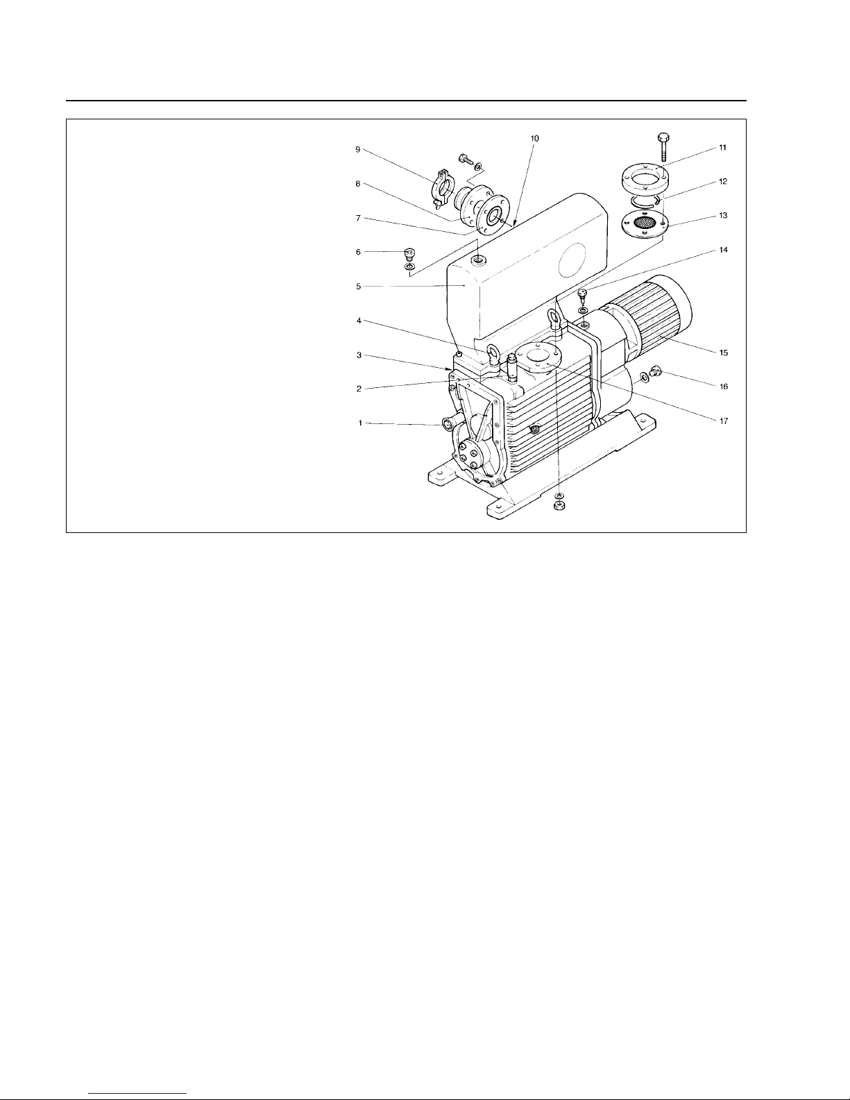
Key to Fig. 7
1 Oil-drain plug screw, pumping chamber
2 Gas ballast activator
3 Oil-level glass
4 Eyebolts for lifting
5 Exhaust box
6 Oil-fill plug screw, pumping chamber
7 Sealing disk
8 Collar flange: E 250, DK 200
9 Clamping ring
10 Exhaust port
11 Collar flange
12 Snap ring
13 Dirt trap
14 Oil-fill plug screw, gear
15 Three-phase motor
16 Oil-drain plug screw, gear
17 Inlet port
Fig. 7 Controls and connections
Page 15

GA 02.200/8.02 - 10/02
Maintenance
15
3.3 Oil Change
3.3.1 Pumping Chamber
Always carry out the oil change when the pump is shut
down but still warm.
If there is a risk of the oil being polymerised owing to the
connected process, the oil should be changed immediately after operation of the pump.
Shut down the pump and wait for a while; the pump is
automatically vented within 2-5 minutes.
Unscrew the oil-drain plug (7/1) and let the used oil drain
into a suitable vessel.
When the flow of oil slows down, reinstall the oil-drain
plug, briefly start the pump (max. 10 s) and then switch
it off.Unscrew the oil drain plugs and drain the remaining
oil.
Single-stage pumps (E series) only: Unscrew the oildrain plug below the oil-level glass and drain the oil.
Reinstall the plug with gasket.
Reinstall the oil-drain plug(s) (check the O-ring and gasket ring and replace them if necessary). Remove the
plug (7/6) from the oil-fill port.
In the event of considerable contamination, the pump
can be flushed as follows.
Use only pump oil for flushing the pump;do
not use solvent for this purpose.
Fill the pump with at least half of the quantity of oil needed for operation (see Section 1.3) and let the pump run
for approx. 5 min. with the inlet por t closed. Then drain
the oil. If necessary, repeat this flushing procedure.
Then fill in the oil quantity required for operation (see
Section 1.3) and reinstall the oil-fill plug with gasket.
3.3.2 Gear
Shut down the pump.
Unscrew the oil-drain plug (7/16) and let the used oil
drain into a suitable vessel. Reinstall the oil-drain plug
(7/16) with gasket.
Unscrew the oil-fill plug (7/14), fill in approx. 0.1 ltr oil,
reinstall the oil-fill plug and start the pump briefly.
Switch off the pump, drain the oil used for flushing and
firmly reinstall the oil-drain plug (7/16) with gasket.
Unscrew the oil-fill plug (7/14) and fill in the required
quantity of oil (see Section 1.3 – Technical Data).
Reinstall the oil-fill plug with gasket.
Use only the original oil-fill plug or the proper spare.This plug contains a venting device for avoiding excessive pressure in the
gear housing.
3.4 Cleaning the Dirt Trap
In the pump's inlet port there is a wire-mesh filter acting
as a dirt trap for contaminants (7/13). It should be kept
clean at all times in order to avoid a reduction of the
pumping capacity.
For this purpose, disconnect the intake line, remove the
dirt trap from the inlet port and r inse it in a vessel using
a suitable solvent.Then thoroughly dry it with compressed air.
If the dirt trap is faulty, replace it.
The cleaning intervals depend on requirements. If large
amounts of abrasive materials occur, a dust filter should
be inserted in the intake line (see Section 1.3).
3.5 Cleaning the Pump
In the case of special operating conditions (intake of particles, high vapour loads, uptake of liquids or similar) we
recommend preventive maintenance on the components
and the exchange of wearing parts.The intervals for this
depend very much on the type of process.
Caution
Caution
Page 16
GA 02.200/8.02 - 10/02
Maintenance
16
3.6 Disassembling and
Reassembling the Pump
This kind of work should be left to trained
personnel. At this point we recommend our
practical training courses.
Please note especially the safety information given in Chapter 3 on page 13.
3.6.1 Preparations
- Wear suitable protective clothing.
- There exists the danger that someone
may slip on spilt oil.
- Ensure compliance with the relevant
safety and environmental regulations.
- Please note especially the safety information given in Chapter 3 on page 13.
Disconnect the motor.
Drain the oil (see Section 3.3).
Remove the pump from the vacuum system.
Place the pump in an oil pan to catch any residual oil
from the pump during disassembly.
3.6.2 Disassembling the Valves and Oil
Level Glass
Remove the exhaust box (7/5).
Unscrew the T-screw connections (8/6), tubing (8/8) and
adaptor for the gas ballast (8/5).
On single-stage pumps, each pumping chamber has an
exhaust valve and a gas ballast valve with tubing. On
two-stage pumps, each pumping chamber has an
exhaust valve, but only the second stage has a gas ballast valve.
Unscrew the valve holder (8/4) (special tool 9) and remove the exhaust and gas ballast valve assembly (8/3).
Disassemble the oil-lev el glass (8/2) only if it is very dirty
or damaged or has a leak. It can be unscrewed using a
socket screw wrench.
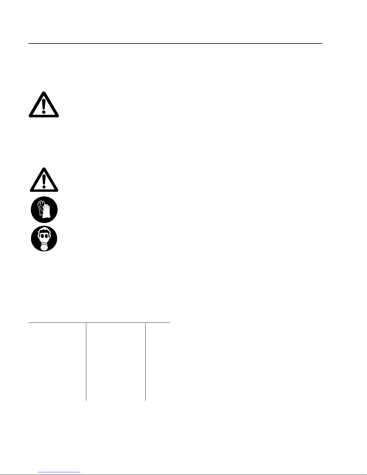
Warning
Warning
Torque for the screws in Nm
Pinion gear mount M 10 x 35 55 Nm
Exhaust valve M 8 x 50 30 Nm
Casing lid
- left M 8 x 30 30 Nm
- at the motor M 8 x 25 30 Nm
Exhaust box M 8 x 25 30 Nm
Casing lid (DK) M 8 x 20 30 Nm
Gear box M 8 x 50 30 Nm
Page 17
GA 02.200/8.02 - 10/02
Maintenance
17
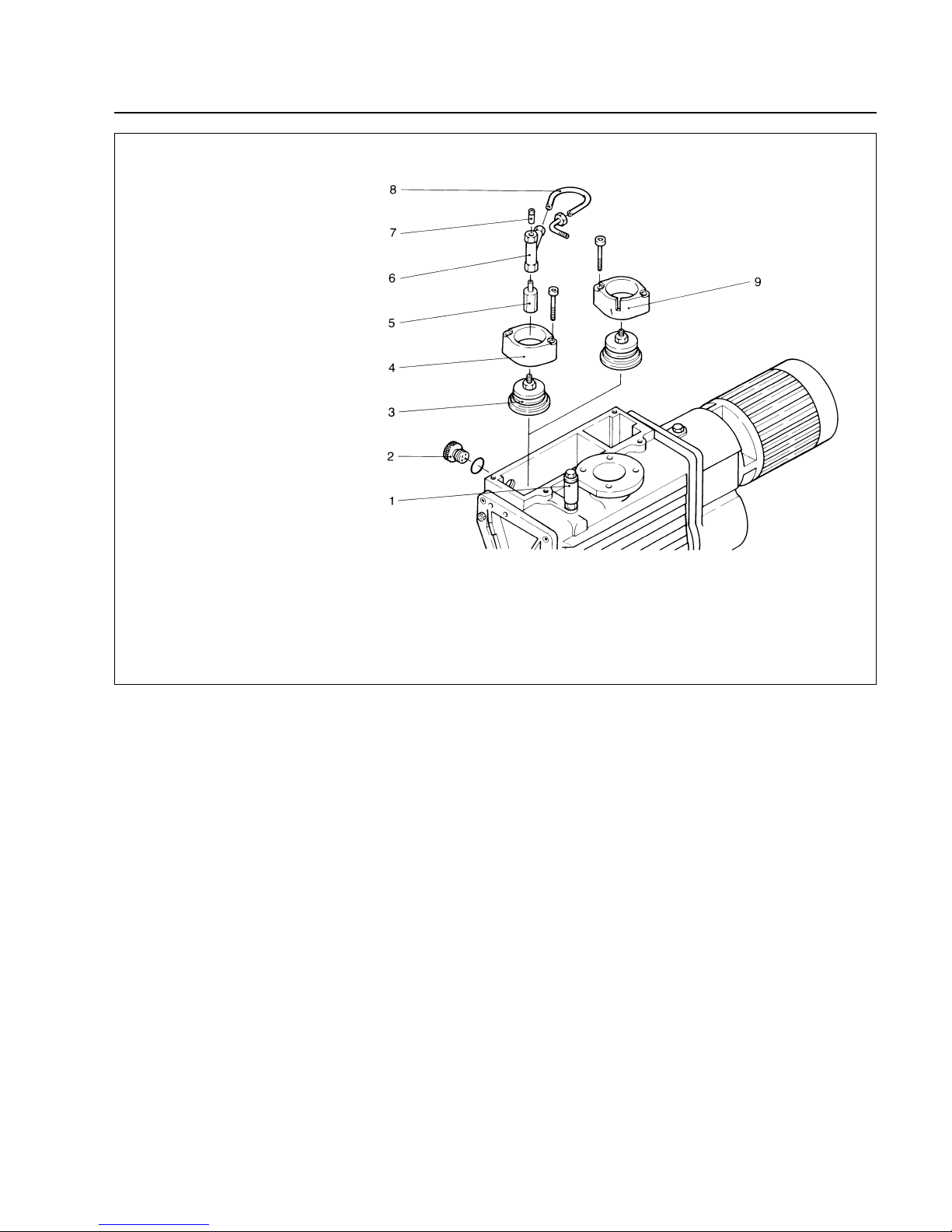
Key to Fig. 8
1 Gas ballast activator
2 Oil-level glass
3 Exhaust and gas ballast valve assembly
4 Valve holder without oil drain groove
5 Gas ballast adaptor
6 T-screw connection
5 Silencer nozzle
8 Tubing
9 Valve holder with oil drain groove
(on two-stage pumps only)
Fig. 8 Valves
Page 18

GA 02.200/8.02 - 10/02
Maintenance
18
3.6.3 Disassembling the Motor End
(see Fig. 9)
Remove the motor (9/9).
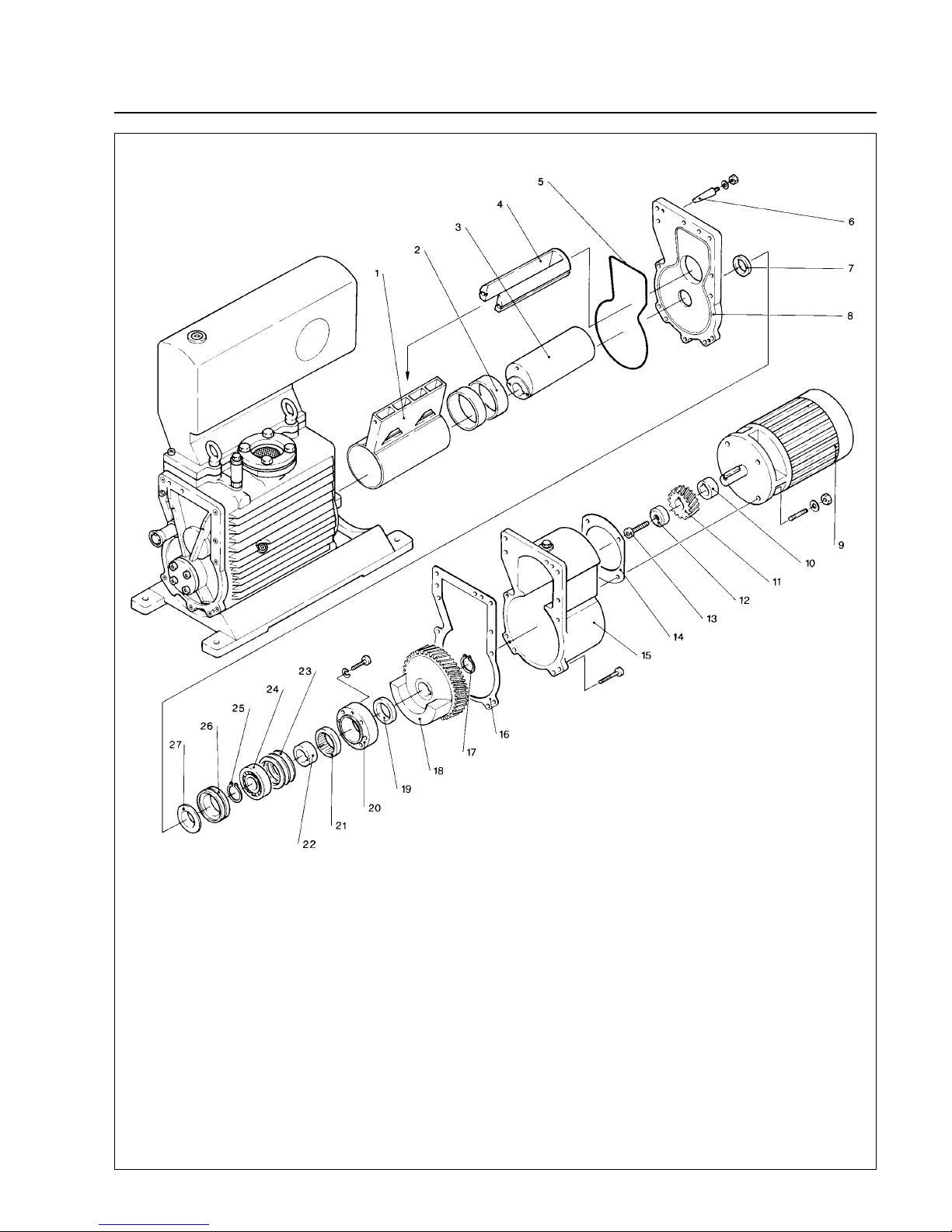
Only if the pinion gear (9/11) is to be replaced: Remove
the screw (9/13) and pull off the pinion gear (9/11) (special tool 5).Otherwise, the screw, pinion gear and spacer
bushings (9/12) and (9/10) can be left on the drive shaft.
Remove the gasket (9/14).
Remove the gear housing (9/15).
Remove the gasket (9/16).
Remove the retainer ring (9/17).
Pull off the ring gear (9/18) (special tools 4 and 7).
Remove the spacer (9/19).
Note
If the parts (9/20) to (9/26) do not have to be replaced,
mark them or place them in the right order for reassembly.
Unscrew the outer race (9/20).
Remove the inner race (9/22) with reverse lock (9/21).
Remove the shim(s) (9/23).
Remove the key from the shaft.
Pull off the ball bearing (9/24) (special tools 6 and 7).
Remove the retainer ring (9/25).
Remove the spacer (9/26).
It is advisable always to replace the L-ring
shaft seal (9/27) and the radial shaft seal
(9/7).
Pull the L-ring shaft seal (9/27) off from the shaft.
Loosen two screws on the front end plate (9/8) and
remove the plate with O-ring (9/5).If the plate cannot be
moved, screw 2 nuts onto the protruding threads of the
dowel pins and force the plate off.
Remove the radial shaft seal (9/7) from the front end
plate.
Pull the slide valve (9/4) out of the pump body.
Pull the piston (9/1) off the cam.
Only if the piston bushings (9/2) are damaged:Force the
bushings out of the piston.
Pull the cam (9/3) off the shaft (special tools 1 and 7).
To remove the piston and cam from the middle pumping
chamber on E 250 and DK 200, see Section 3.6.5.
Caution
Page 19
GA 02.200/8.02 - 10/02
Maintenance
19
Key to Fig. 9
1 Piston
2 Piston bushings
3 Cam
4 Slide valve
5 O-ring
6 Tapered dowel pins
7 Radial shaft seal
8 Front end plate
9 Three-phase motor
10 Spacer bushing
11 Pinion gear
12 Spacer bushing
13 Screw
14 Gasket
15 Gear box
16 Gasket
17 Retainer ring
18 Ring gear
19 Spacer
20 Outer race
21 Reverse lock
22 Inner race
23 Shims
24 Bearing
25 Retainer ring
26 Spacer
27 L-ring shaft seal
Fig. 9 Disassembling and assembling the motor side
Page 20
GA 02.200/8.02 - 10/02
Maintenance
20
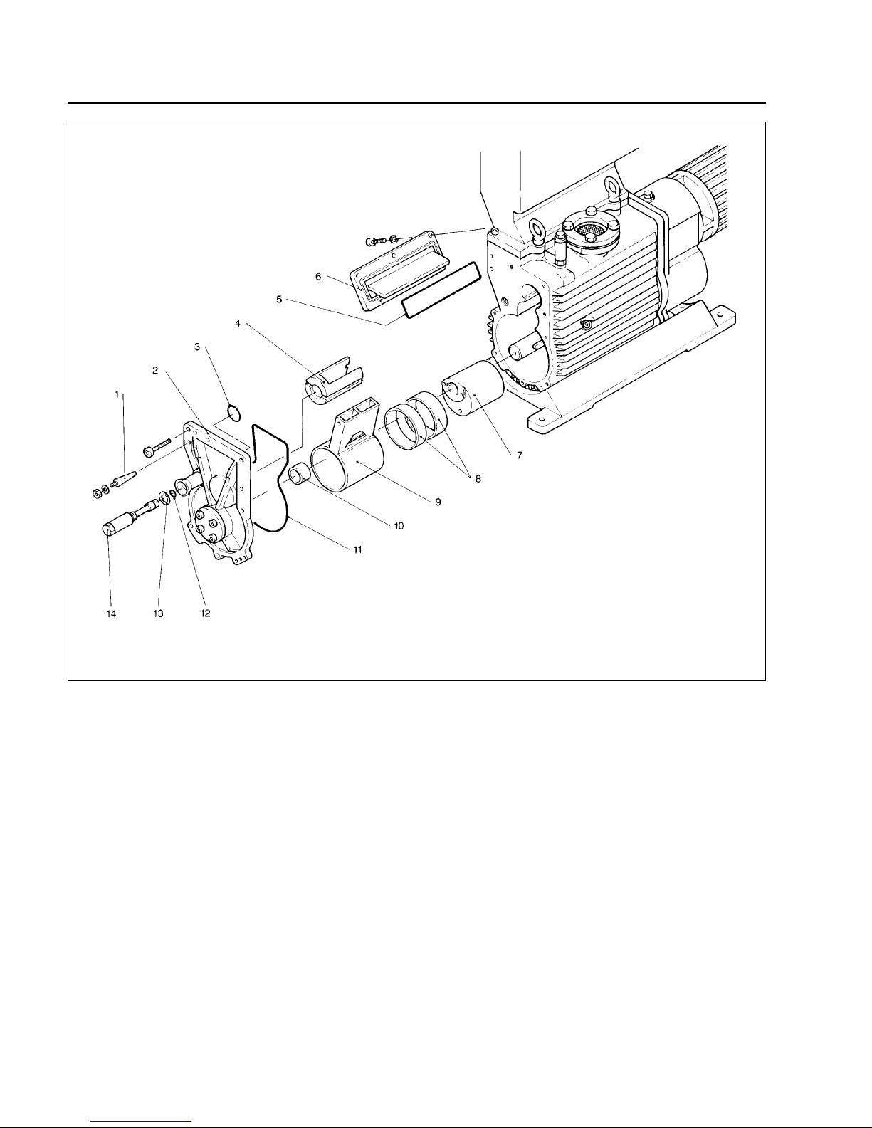
3.6.4 Disassembling the Front End
Remove the fastening screws of the rear end plate
(10/2).
Tighten the nuts on the 2 tapered dowel pins (10/1) until
the pins are loose.
Remove the rear end plate (10/2) with O-ring (10/11).
Pull out the slide valve (10/4).
Pull the piston (10/9) off the cam.
Only if the piston bushings (10/8) are damaged: Force
the bushings out of the piston.They must be replaced if
their Teflon coating is damaged.
Pull the cam (10/7) off the shaft (special tools 1 and 7).
If the shaft bushing (10/10) is damaged, force it out of the
rear end plate.
Remove the side cover (10/6) with O-ring (10/5).
Key to Fig. 10
1 Tapered dowel pin
2 Rear end plate
3 O-r ing
4 Slide valve
5 O-r ing
6 Side cover
7 Cam
8 Piston bushing
9 Piston
10 Shaft bushing
11 O-ring
12 O-ring
13 Gasket ring
14 Oil-drain plug screw
Fig. 10 Disassembling the front end
Page 21
GA 02.200/8.02 - 10/02
21
Maintenance
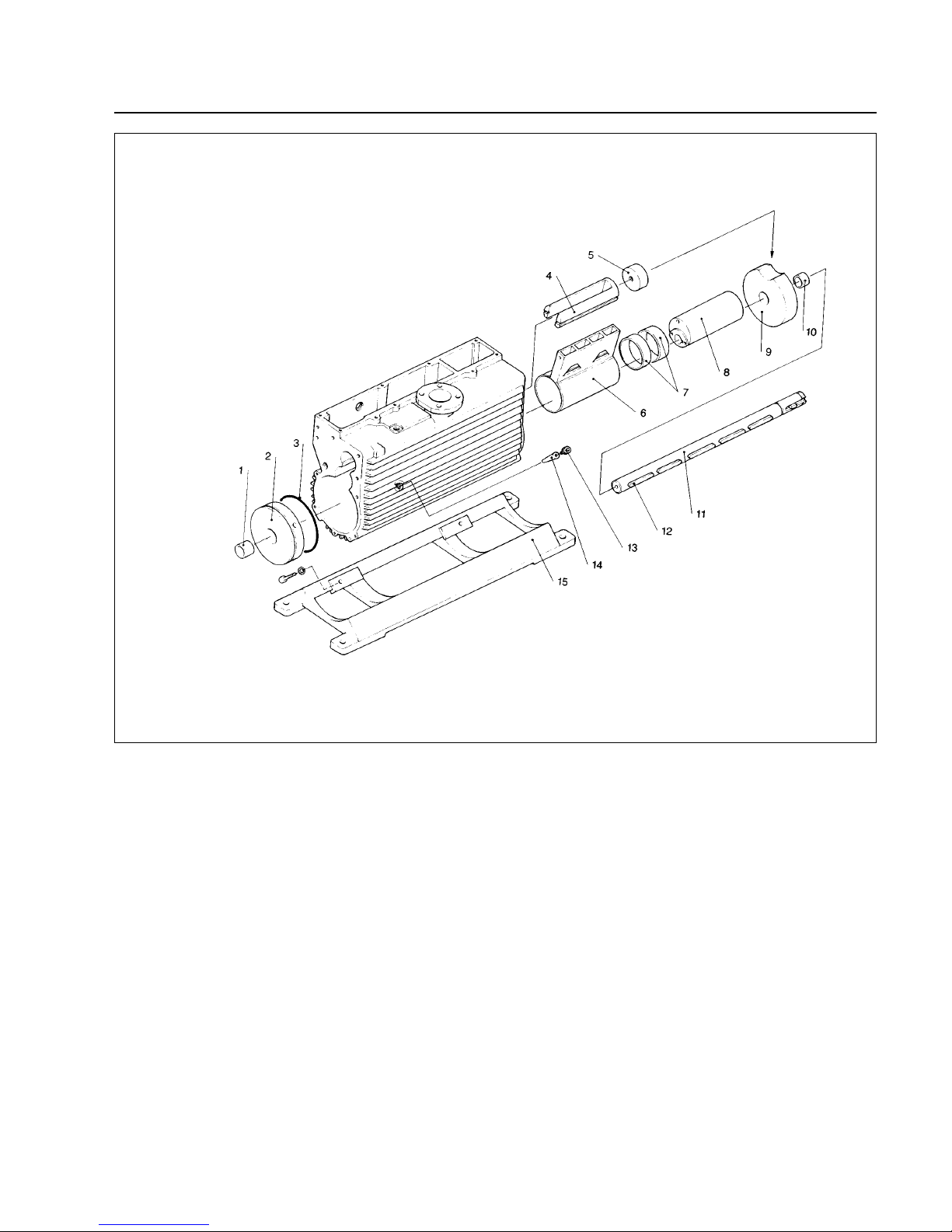
3.6.5 Removing the Shaft and Intermediate
Plate(s)
On E 250 and DK 200 only:These two pump types have
3 pumping chambers. The two chambers at the motor
end are separated by a loose intermediate plate (11/9).
Remove the disk (11/5).
Pull the loose intermediate plate (11/9) out of the pump
body (special tools 1 and 7).
If the shaft bushing (11/10) is damaged, force it out of the
loose intermediate plate.
Pull the slide valve (11/4) out of the pump body.
Pull the piston (11/6) off the cam (11/8).
Pull the cam off the shaft (special tools 1 and 7).
If the piston bushings (11/7) are damaged, force them
out of the piston (11/6).
For all pump types:
Remove the key (11/12) and pull the shaft (11/11) out
toward the motor end.
Unscrew the screw plug (11/13) and pull out the tapered
pin (11/14) (special tool 2).
Place the pump body on its side.
Unscrew the foot (11/15).
Unscrew two more screw plugs under the pump and pull
out two tapered dowel pins.
Pull out the intermediate plate (11/2) with O-ring (11/3)
(special tool 8).
If the shaft bushing (11/1) is damaged, force it out of the
intermediate plate.
Key to Fig. 11
1 Shaft bushing
2 Intermediate plate
3 O-ring
4 Slide valve
5 Disk
6 Piston
7 Piston bushing
8 Cam
9 Loose intermediate plate
10 Piston bushing
11 Shaft
12 Key
13 Screw plug
14 Tapered pin
15 Foot
Fig. 11 Removing the shaft and intermediate plate(s); removing the middle piston and cam on E 250 and DK 200
Page 22
Maintenance
3.6.6 Cleaning the Parts and Checking for
Wear
Inspect all surfaces for scratches, marks, running-in
tracks or other damage.If possible, carefully smooth the
surfaces with emery paper.
If the parts are considerably damaged,
especially sealing surfaces or keyways,
replace them. In the case of seals and Orings always use new parts.
Using suitable wires, ensure that all oil channels are
clear of dirt. Blow compressed air through the channels
and clean all parts with a suitable solvent and then dry
them thoroughly with compressed air.
Check that all keys are clean and fit snug in their
keywa ys and that the cams and the ring gear can be pushed without difficulty onto the shaft with its keys.If necessary, rub the parts with emer y paper and then clean
them again.
Unscrew and clean the gas ballast valve. All parts, including gaskets and O-rings needed for assembly, should
be moistened with pump oil.
3.6.7 Reassembling the Pump
Reassemble the pump in the reverse sequence.
Observe the following:
Inserting the intermediate plate
When pulling the intermediate plate (12/2) back in (special tool 8), ensure that the O-ring (12/3) is not damaged.
Counterbalancing
When installing the ring gear and cams, make sure that
the cams and ring-gear counterbalance are fitted alternately at the top and bottom so that the pump remains
counterbalanced (see Fig. 3).
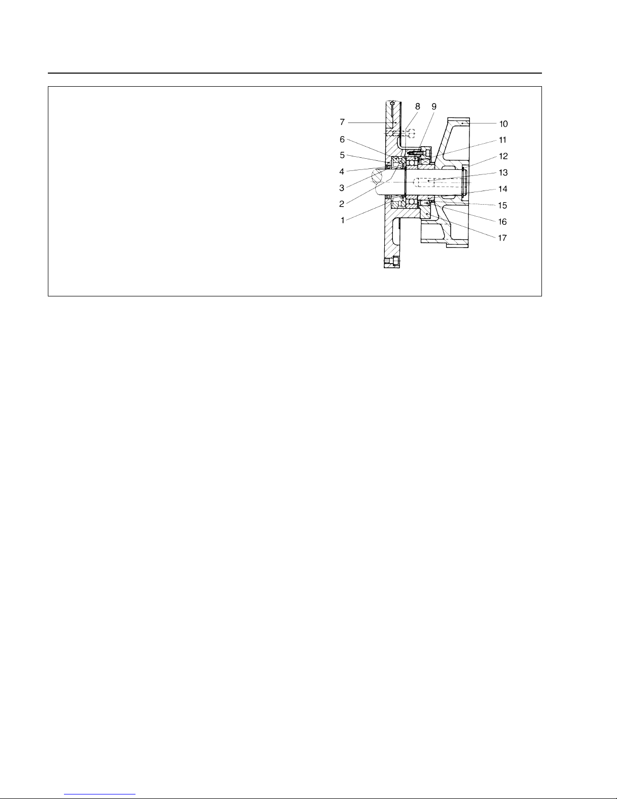
Inserting the radial shaft seal
Using a suitable tool, force in the radial shaft seal from
the interior side of the front end plate (for position of radial shaft seal, see Fig. 12).
Selecting the shims
One or more shims (9/23) have to be inserted between
the ball bearing (9/24) and the outer race (9/20). To
determine the correct thickness, proceed as follows:
As a trial, mount one or more 1 mm thick shims.
Attach the outer race, but tighten the screws only by
hand.
Using a thickness gauge, measure the gap between the
front end plate and outer race.
The correct thickness of the shims is obtained as follows:
1.00 mm minus gap measured plus 0.10 mm
Remove the 1 mm thick shims mounted f or trial purposes
and insert shims of the thickness calculated.
Example: Gap measured is 0.70 mm
Thickness of shim(s) required:
1.00 mm - 0.70 mm + 0.10 mm = 0.40 mm
22
GA 02.200/8.02 - 10/02
Key to Fig. 12
1 L-ring shaft seal (8/27)
2 Oil flow holes
3 Circular spring on ID of radial shaft seal
4 Radial shaft seal (8/7)
5 Bottom surface of bearing well
6 Spacer (8/26)
7 Front end plate (8/8)
8 Retainer ring (8/25)
9 Bearing (8/24)
10 Ring gear (8/18)
11 Shims (8/23)
12 Retainer ring (8/17)
13 Key
14 Inner race (8/22)
15 Spacer (8/19)
16 Reverse lock (8/21)
17 Outer race (8/20)
Fig. 12 Cross-section of the bearing in the motor lid (see also Fig. 9)
Caution
Page 23
Maintenance
Mounting the front end plate (9/8) and rear end plate
(10/2)
Before sliding the front end plate with radial shaft seal
onto the shaft and mounting the L-ring shaft seal, push
the sleeve tool (special tool 3) onto the shaft.
Place the O-ring (9/5) or (10/11) into the groove of the
end plate and secure it with some vacuum grease, if
necessary.Remove the nuts and washers from the tapered dowel pins (9/6) or (10/1) and fit the pins in the end
plate.
Carefully push on the end plate with radial shaft seal
over the sleeve tool. Install the fastening screws of the
end plate without tightening them fully. Carefully drive in
the pins and tighten the fastening screws.
Inserting the L-ring shaft seal (9/27) and spacer
(9/26)
Carefully slide the L-ring shaft seal over the sleeve tool.
The end of the seal with the larger diameter should face
the center of the pump.
When withdrawing the sleeve tool, hold the L-ring shaft
seal tight.
The spacer (9/26) has an oil channel, which must point
upward when installed.
Inserting the reverse lock
Secure the screws of the outer race (9/20) with Loctite
271 and tighten them crosswise.
The shoulder of the reverse lock (9/21) faces outward.
Looking from the motor end, the shaft must only turn
counterclockwise.
If it can be turned in both directions, the reverse lock is
faulty; if it can be turned clockwise only, the reverse lock
is the wrong way round.
Inserting the ring gear (9/18)
The side of the ring gear bearing with the lead weight
faces the center of the pump.
Do not force on the ring gear with a hammer. It can be
carefully warmed to make it easier to mount (150 °C
max.).
The shaft has a hole into which a bolt can be screwed for
forcing on the ring gear.After attaching the retainer ring
(9/17), draw back the ring gear as far as this ring (special tool 4).
Fitting the valve
Place the gas ballast valve (8/3) on the valve seat without exposing it to mechanical strain.The threaded holes
for attaching the valve holder (8/4) must be free of grease and clean.Fit the valv e holder with the v alv e .The hex.
socket screws used to attach the valve holder must be
degreased and cleaned before they are inserted. Finally
apply Loctite 271 to the threads.
Screw in the hex.socket screws.The amount of torque is
given in the Table on page 16.
Do not mechanically stress the valve holder
on one side.If this is not observed the pump
may be completely damaged.
Before starting up the pump you must fill the
gear space and the pump chamber with oil.
3.7 Leybold Service
If a pump is returned to LEYBOLD, indicate whether the
pump free of substances damaging to health or whether
it is contaminated.
If it is contaminated also indicate the nature of the
hazard. For this you must use the form which has been
included at the end of these Operating Instructions.
A copy of this form is reproduced at the end of these
Operating Instructions: “Declaration of Contamination of
Vacuum Instruments and Components“.
Please attach this form to the pump or enclose it with the
pump.
This declaration of contamination is required to meet
German law and to protect our personnel.
LEYBOLD must return any pumps without a “Declaration
of Contamination“ to the sender’s address.
The pump must be packed in such a way,
that it will not be damaged during shipping
and so that any contaminants are not released from the package.
23
GA 02.200/8.02 - 10/02
Warning
Caution
Page 24
GA 02.200/8.02 - 10/02
24
Troubleshooting
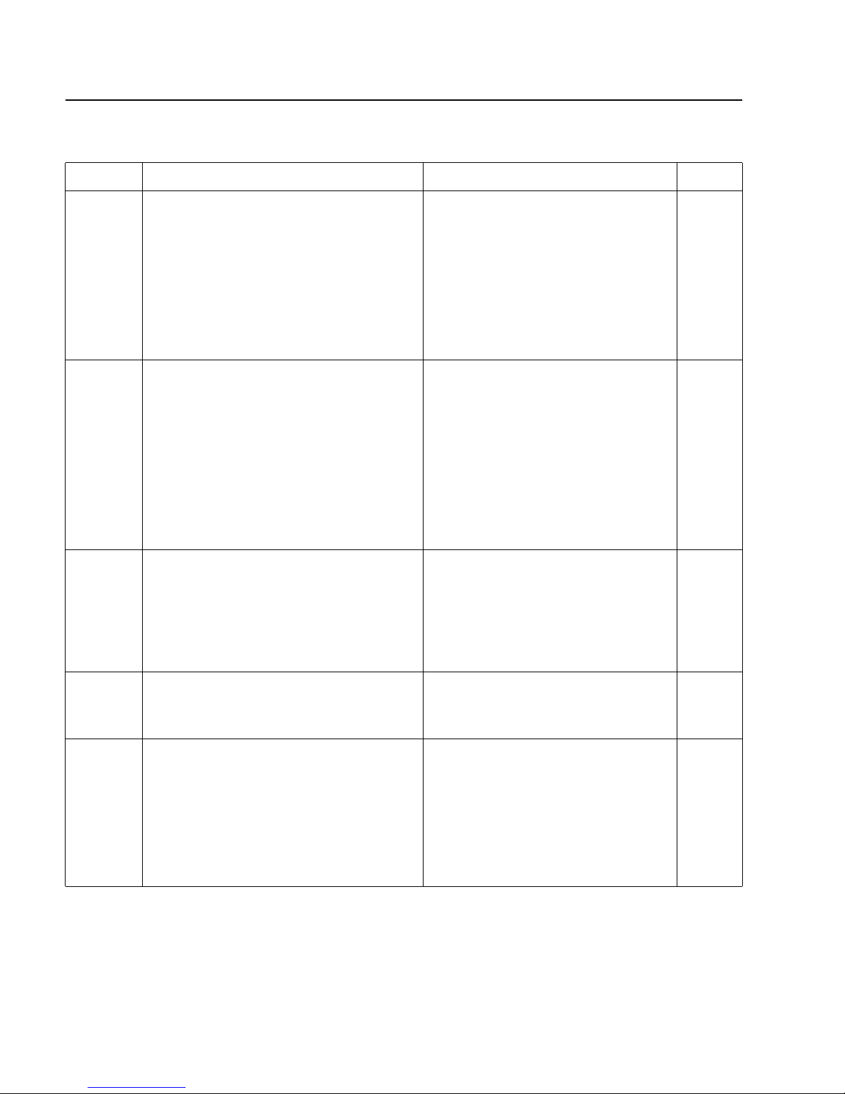
Fault Possible cause Remedy
Repair note
4 Troubleshooting
Pump does not
start.
Motor is connected incorrectly.
Reverse lock prevents start-up.
Blocked exhaust line.
Operating voltage does not match motor rating.
Motor protection switch is set incorrectly.
Motor is malfunctioning.
Oil temperature below 12 °C.
Oil is too thick.
Installed exhaust filter or exhaust line is clogged.
Too much oil has entered motor from gear housing.
Gear or bearings are obstructed or malfunctioning.
(See fault "Pump is seized up").
Connect the motor correctly (wiring diagram in junction box).
Interchange two of the input leads at motor junction box or
install the reverse lock correctly.
Remove the blockage.
Replace the motor.
Set the motor protection switch correctly.
Replace the motor.
Heat the pump and pump oil
or use different oil.
Change the oil.
Replace the filter, clean the exhaust line.
Repair the shaft seal on the motor, fill correct
oil quantity into gear housing.
Repair the pump.
Repair the pump.
Pump does not
reach ultimate
pressure.
Pumping speed
of the pump is
too low.
After switching
off the pump
under vacuum,
pressure in
system rises too
fast.
System has a leak.
SECUVAC valve is not installed or is obstructed.
Check the system.
Install a SECUVAC valve or repair it.
Silencer nozzle is clogged due to
- too much oil in the valve chamber
- contamination
Parts are worn:.
(shaft bushing, cam, ring gear, pinion lammellae and piston).
Cam or ring gear not properly mounted.
Motor bearing faulty.
Motor fan scrapes along the fan cowl.
Foot of the pump is loose.
Valve disc faulty.
Grooves in the shaft and the cam are worn out.
Connecting screw for the oil filter facility has a leak.
Wrong balancing (faulty ring gear).
Drain oil.
Clean nozzle.
Repair the pump.
Repair the pump.
Exchange the motor.
Exchange the fan cowl or repair.
Fix the foot of the pump.
Exchange the valve.
Exchange the faulty components.
Seal the connecting screw (O-ring).
Repair the pump.
Pump is
unusually noisy.
Pump is to small.
Measuring technique or gauge is unsuitable.
External leak 1).
Installed SECUVAC valve closes.
Exhaust valve is malfunctioning.
Oil is unsuitable.
Gas ballast lines in valve chamber have a leak.
Gaskets at oil-drain plug (9/14) are faulty.
Inadequate lubrication of pumping chamber
due to clogged oil lines.
L-ring shaft seal and/or radial shaft seal is faulty.
Inadequate lubrication of pump due to
- insufficient oil
- clogged optional oil filter.
Internal pump parts are excessively worn.
Oil reservoir has not been mounted correctly.
Improperly fitted pistons and vanes after a repair.
Check process data, possibly change the pump.
Use correct method of measurement and instruments.
Repair pump.
Repair valve.
Repair valve.
Change the oil (possibly degas).
Repair gas ballast lines.
Replace gaskets.
Clean the pump.
Repair the pump.
Top up oil.
Clean the filter.
Repair the pump, replace worn parts.
Install the oil reservoir correctly.
Repair the pump.
Clean the dirt trap;
Precaution: install a dust filter in intake line.
Clean the filter.
Replace the filter elements.
Use adequately wide and short connecting lines. The diameter of the connecting line should be the same as for the
connections at the pump.
Let the pump run warm with open gas ballast valve.
Repair the pump; replace the wor n par ts.
Leak detection and removal of the leak.
Dirt trap in the inlet port is clogged.
Installed dust filter is clogged.
Installed exhaust filter is clogged.
Connecting lines are too narrow or long (throttling).
Pump is too cold.
Internal pump parts are excessively worn.
Leak in the intake line.
Page 25
GA 02.200/8.02 - 10/02
25
Troubleshooting
Pump gets hotter
than previously
observed.
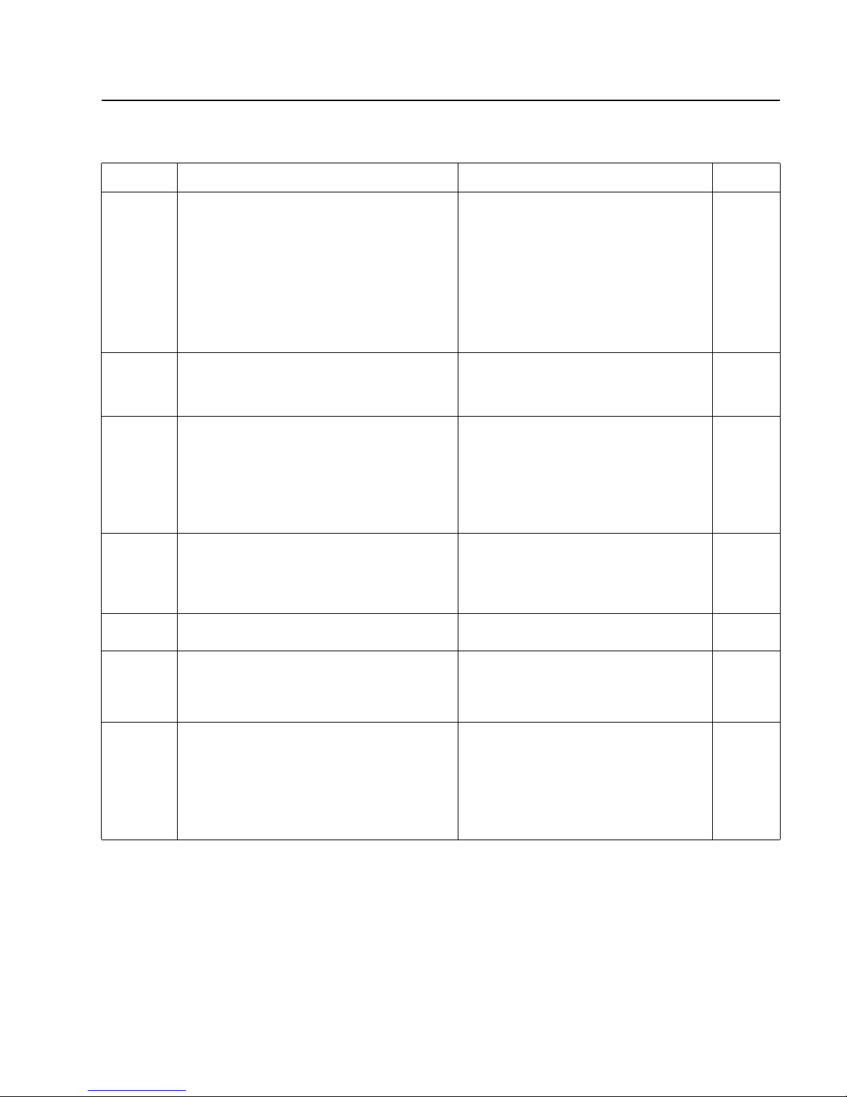
Fault Possible cause Remedy
Pump is seized
up.
Oil has broken down due to oil not being changed often enough
or to pump overheating.
Corrosion of metal surfaces due to condensation
in pump.
Oil has become resinified.
Inadequate lubrication of pumping chamber due to clogged oil
channels.
Foreign particles in the pump.
Repair the pump; precaution: change the oil more often or
do not let the pump get so hot (see fault "Pump gets hotter
than previously observed.").
Repair the pump; precaution: run the pump with gas ballast
or install a condensate trap.
Repair the pump; precaution: install an oil filter or use different oil.
Repair the pump.
Use an intake filter.
Pump looses oil. Radial shaft seal is faulty.
Too much oil in gear housing.
Oil-drain plugs are not tight.
Gaskets are damaged.
Impact panel in the exhaust box is faulty
Repair the pump.
Drain the oil, fill in correct oil quantity.
Replace the gaskets of oil-drain plugs or
the oil-drain plugs.
Replace the gaskets.
Repair the impact panel.
*) This column refers to the section in the Operating Instructions that contains the applicable repair information.
1) Bubble test. Let the pump run at operating temperature with degassed oil, without gas ballast and with closed inlet port.
Immerse the exhaust line in a vessel with water. If a steady flow of bubbles appears, the pump has an external leak.
Repairnote
Air intake or discharge surfaces of the cooler
are obstructed or dirty.
Ambient or intake temperatures are too high.
Oil cycle is not working.
Oil has broken down or is contaminated.
Incorrect oil level, not enough oil in the pump.
Installed exhaust filter or exhaust line is obstructed.
Exhaust valve is malfunctioning.
Continuous intake pressure > 200 mbar.
Gas ballast lines have a leak.
Excessive internal friction due to faulty parts.
Continuous intake pressure > 500 mbar (absolute).
- Insufficient lubrication.
Set up the pump correctly or clean the cooler.
40 °C max. are per missible.
Clean or repair the oil lines and channels.
Change the oil.
Top up oil, note correct oil level.
Replace the exhaust filter or clean the exhaust line.
Repair the valve.
Change the operating conditions, continuous intake
pressure < 200 mbar.
Repair the lines.
Repair the pump.
Change the operating conditions, continuous intake pressure < 500 mbar.
Replace the exhaust filter.
Drain the excess oil.
Alter the operating conditions.
Find the leak and seal it.
Replace the valve.
Installed exhaust filter is clogged or damaged.
Too much oil.
Intake pressure is too high.
Vacuum system or lines have a leak.
Exhaust valve is faulty.
Oil consumption
is too high, oil
mist in the
exhaust.
Oil comes from vacuum system.
SECUVAC valve is not installed or is obstructed.
Sealing surfaces of SECUVAC valve are damaged or dirty.
Motor turns in the wrong direction.
Too much oil.
Vapour pressure of oil is too high.
Excessive pressure in exhaust line.
Oil-drain plug or its O-ring is faulty.
Oil in the intake
line or vacuum
vessel.
Check the system.
Install a SECUVAC valve or repair it.
Clean or repair the valve.
Interchange two of the input leads at motor junction box;
replace the reverse lock.
Drain the excess oil.
Change the oil.
Clear the exhaust line or clean the installed exhaust filter.
Replace the oil-drain plug or O-ring.
Degas the oil or change the oil and clean the pump;
precaution: open gas ballast valve or insert a separator.
Check the operating conditions ahead and after the pump
Install the exhaust line with a downward slope or install a
condensate trap.Check operating conditions (vapour
tolerance).
Condensation in the pump due to
- too much vapour
- pump too cold.
Exhaust line is not installed correctly.
Oil is turbid.
Change the oil.
Change the oil (see fault "Pump gets hotter than previously
observed."). Check operating conditions.
Oil has broken down.
Oil is too hot.
Oil is unusually
dark.
Page 26
GA 02.200/8.02 - 10/02
26
We - Leybold Vacuum GmbH - herewith declare that the
products defined below meet the basic requirements
regarding safety and health of the relevant EC directives
by design, type and the versions which are brought in to
circulation by us.
In case of any products changes made without our
approval, this declaration will be void.
Designation of the products: Rotar y piston pump
Types: E 250;
DK 200
Cat. Nos.: 105 36
111 16
895 08
895 09
895 10
166 17
166 37
EC Declaration of Conformity
The products conform to the following directives:
• EC Directive on Machinery (98/37/EG)
• EC Directive on Low-Voltages (73/23)+(93/68/EWG)
• EC EMC Directive (89/336/EWG)
(91/263/EWG) + (92/31/EWG) + (93/68/EWG)
Applied harmonised standards:
• DIN EN 292 Part 1 11.91
• DIN EN 292 Part 2 06.95
• DIN EN 1012 Part 2 07.96
• DIN EN 60 204 Part 1 11.98
• DIN EN 50 081 - Part 1 03.93
• DIN EN 50 081 - Part 2 03.94
• DIN EN 50 082 - Part 1 11.97
• DIN EN 50 082 - Part 2 02.96
Applied national standards and technical
specifications:
• DIN 31 001 April 1983
Cologne, October 28, 2002
—————————————————————
Hauck, BU Head SPS
Division Industrial
Cologne, October 28, 2002
—————————————————————
Dr.Beyer, Development Head SPS
Division Industrial
Page 27
27
GA 02.200/8.02 - 10/02
Applied harmonised standards:
• DIN EN 292 Part 1 11.91
• DIN EN 292 Part 2 06.95
• DIN EN 1012 Part 2 07.96
• DIN EN 60 204 Part 1 11.98
• DIN EN 50 081 Part 1 03.93
• DIN EN 50 081 Part 2 03.94
• DIN EN 50 082 Part 1 11.97
• DIN EN 50 082 Part 2 02.96
Applied national standards and technical
specifications:
• DIN 31 001 April 1983
We – Leybold Vacuum GmbH – herewith declare that
operation of the incomplete machine defined below, is
not permissible until it has been determined that the
machine into which this incomplete machine is to be
installed, meets the regulations of the EEC Directive on
Machinery.
Designation of the products: Rotar y piston pump
Types: E 250;
DK 200
Cat. Nos.: 166 17
166 37
EEC Manufacturer’s Declaration
in the sense of the Directive on Machinery 89/392/EWG, Annex IIb
Cologne, October 28, 2002
—————————————————————
Hauck, BU Head SPS
Division Industrial
Cologne, October 28, 2002
—————————————————————
Dr.Beyer, Development Head SPS
Division Industrial
Page 28
28
GA 02.200/8.02 - 10/02
Page 29

GA 02.200/8.02 - 10/02
29
Page 30

LISS_05171_2002 BICOM/OF 10.02
Printed in Germany on chlorine-free bleached paper
GA 02.200/8.02 - 10/02
LEYBOLD V AKUUM GmbH
Bonner Strasse 498 (Bayenthal)
D-50968 Cologne
Tel.: +49 (0)221 347-0
Fax: +49 (0)221 347-1250
http://www.leyboldvac.de
e-mail:[email protected]
USA:
LEYBOLD VA CUUM USA
5700 Mellon Road
Export, PA 15632
Phone: +1-724-327 57 00
Fax: +1-724-733 12 17
Internet:http://www.
leyboldvacuum.com
Canada:
LEYBOLD Canada Inc.
7050 Telford Way, Unit 5
Mississauga, Ontario
Canada L5S 1V7
Phone: +1-905-672 77 04
Fax: +1-905-672 22 49
e-mail:
[email protected]
AMERICA EUROPE ASIA
Germany
LEYBOLD VAKUUM
GmbH
Bonner Straße 498
D-50968 Cologne
Phone: +49-221-347-1234
Fax: +49-221-347-1245
Internet: www.leyboldvac.
de
e-mail:
sales
@
leybold
vakuum.com
Belgium/Netherlands/
Luxemburg:
LEYBOLD N.V.
Leuvensesteenweg 542, 9A
B-1930
Zaventem
Phone: +32-2-71 10 083
Fax: +32-2-72 08 338
LEYBOLD B.V.
Computerweg 7
NL-3606 AV Maarssen
Phone: +31-346-583 999
Fax: +31-346-583 990
France
LEYBOLD S.A.
7, Avenue du Quebec
Z.A. de Cour taboeuf, B.P. 42
F-91942
Courtaboeuf
Cedex
Phone: +33-1-69 82 48 00
Fax: +33-1-6907 57 38
e-mail:
Compuserve:100635,43
Great Britain/Ireland:
LEYBOLD LTD.
Waterside Wa y,
Plough Lane
GB-London SW 17 OHB
Phone: +44-208-9717000
Fax: +44-208-9717001
Italy
LEYBOLD S.P.A.
Via T r asimeno 8
I-20128 Milano
Phone: +39-02-27 22 31
Fax: +39-02-27 20 96 41
Spain
LEYBOLD S.A.
C/. Mataró, 27
Polígono Industrial Les
Grases
E-08980 Sant Feliu de
Llobregat (Barcelona)
Phone: +34-93-666 46 16
Fax: +34-93-666 43 70
Sweden:
LEYBOLD AB
Box 9084
40092 Göteborg
Phone: +46-31-68 84 70
Fax: +46-31-68 39 39
Switzerland/
Liechtenstein:
LEYBOLD AG
Leutschenbachstraße 55
CH-8050 Zürich
Phone: +41-1-308 40 50
Fax: +41-1-302 43 73
Peoples Republic of
China:
LEYBOLD (Tianjin)
VACUUM EQUIPMENT
MANUFACTURING Co.,
Ltd.
Beichen Economic Development Area (BEDA)
Tianjin 300400, China
Phone: +86-22 26 972 016
Fax: +86-22 26 972 017
e-mail:
Japan:
LEYBOLD Co., Ltd.
Head Office
Tobu A.K. Bldg. 4th Floor
23-3, Shin-Yokohama 3chome
Kohoku-ku,Yokohama-shi
Kanagawa ken 222-0033
Phone: +81-45-471 33 30
Fax: +81-45-471 33 23
Korea:
LEYBOLD Korea Ltd.
4th Fl. Shinan Bldg., 173-1
Jangchoog-dong 2ga,
Choong-ku
Seoul 100-392, Korea
C.P.O. Box 709
Phone: +82-2-227 11 567
Fax: +82-2-227 11 568
Singapore:
BALZERS and LEYBOLD
Singapore Pte. Ltd.
1 Tuas South Street 3
Singapore 638043
Phone: +65-865 18 65
Fax: +65-862 22 95
Taiwan:
LEYBOLD T aiw an, Ltd.
2 F, No 416-1, Sec. 3
Chung-Hsin Rd.
Chu T ung, Hsinchu.
Taiwan R.O.C:310
Phone: +886-3-583 39 88
Fax: +886-3-583 39 99
Sales Net Worldwide
 Loading...