

Page 1
Operating Manual
GA10218_002_C0
Part numbers
250000V01
250001V01
250002V01
251000V01
251001V01
251100V01
251101V01
Page 2

Content
Important safety information 5
1 Description 9
1.1 Design and Function .................................................................... 9
1.1.1 Vacuum Diagram PHOENIX L300i .............................................. 10
1.1.2 Vacuum Diagram PHOENIX L300i DRY ...................................... 11
1.1.3 Vacuum Diagram PHOENIX L300i MODUL ................................ 12
1.1.4 Vacuum Method ........................................................................ 13
1.1.5 Partial Flow Method ................................................................... 14
1.1.6 Sniffer Mode .............................................................................. 14
1.2 Supplied Equipment ................................................................... 14
1.3 Technical Data ........................................................................... 15
1.3.1 Technical Data PHOENIX L300i ................................................. 15
1.3.2 Technical Data PHOENIX L300i DRY ......................................... 17
1.3.3 Technical Data PHOENIX L300i MODUL .................................... 19
1.3.4 Dimensional Drawings ................................................................ 21
1.4 Ordering Information .................................................................. 24
1.5 Accessories ............................................................................... 24
1.6 Default Settings .......................................................................... 26
2 Installation 27
2.1 Placement ................................................................................. 27
2.2 Conforming Utilisation ................................................................ 27
2.3 Ambient Conditions ................................................................... 27
2.4 Electrical Connections ................................................................ 27
2.4.1 Mains Power .............................................................................. 27
2.4.2 Connection for the Controller Signal and Accessories ................ 29
2.4.3 Vacuum Connections ................................................................. 32
3 Operation 34
3.1 Media Compatibility/Purge Gas .................................................. 34
3.2 Start-Up ..................................................................................... 34
3.2.1 Display ....................................................................................... 34
3.2.2 The Display in Run-Up Mode ..................................................... 35
3.2.3 The Display in Standby Mode ..................................................... 35
3.2.4 Gas Ballast/Purge ..................................................................... 35
3.2.5 The Display in Measurement Mode ............................................ 35
3.2.6 Call for Calibration ...................................................................... 36
GA10218_002_C0 - 10/2016 - © Leybold GmbH
2
Page 3

3.2.7 Speaker Volume ........................................................................ 36
3.2.8 Status Line in the Display ........................................................... 36
3.2.9 Measurement Mode with Bargraph ............................................ 37
3.2.10 Measurement Mode with Trend Information ............................... 37
3.3 First Operation Check ................................................................ 37
3.4 Control Panel ............................................................................. 39
3.5 Interfaces ................................................................................... 44
3.6 Operation .................................................................................. 51
3.6.1 Main Menu ................................................................................ 52
3.6.2 View .......................................................................................... 54
3.6.3 Scale Linear/Logarithmic ........................................................... 54
Content
3.6.4 Display-Range Auto/Manual ...................................................... 55
3.6.5 Time Axis ................................................................................... 56
3.6.6 Contrast .................................................................................... 56
3.6.7 Background in standby .............................................................. 57
3.6.8 Lower Display Limit .................................................................... 57
3.7 Mode ......................................................................................... 58
3.8 Trigger & Alarms ........................................................................ 59
3.8.1 Trigger Level 1 ........................................................................... 59
3.8.2 Trigger Level 2 ........................................................................... 60
3.8.3 Trigger Level 3 ........................................................................... 60
3.8.4 Units .......................................................................................... 60
3.8.5 Volume ...................................................................................... 61
3.8.6 Alarm Delay ............................................................................... 61
3.8.7 Audio Alarm Type ...................................................................... 62
3.9 Calibration ................................................................................. 63
3.10 Settings ..................................................................................... 64
3.10.1 Vacuum Settings ....................................................................... 65
3.10.2 Filter & Background ................................................................... 73
3.10.3 Mass ......................................................................................... 75
3.10.4 Miscellaneous (Language, Calibration request, Service interval...) 75
3.10.5 Parameter Save/Load ................................................................ 78
3.10.6 Monitoring Functions ................................................................. 78
3.11 Information ................................................................................ 82
3.11.1 Service ...................................................................................... 83
GA10218_002_C0 - 10/2016 - © Leybold GmbH 3
Page 4

Content
3.12 Access Control .......................................................................... 83
3.12.1 Zero ........................................................................................... 83
3.12.2 Access to CAL Function ............................................................ 84
3.12.3 Change Menu-PIN ..................................................................... 84
3.13 Calibration ................................................................................. 84
3.13.1 Introduction ............................................................................... 84
3.13.2 The calibration Routines ............................................................. 85
3.13.3 Internal Calibration ..................................................................... 85
3.13.4 External Calibration .................................................................... 86
3.14 Switching Off/Shutting Down ..................................................... 88
4 Maintenance 89
4.1 Safety Information ...................................................................... 89
4.2 Maintenance Intervals ................................................................ 89
4.3 Service at Leybold ..................................................................... 89
4.4 Maintenance Work ..................................................................... 90
4.4.1 Opening of the PHOENIX L300i ................................................. 90
4.4.2 Exchanging the Filter Mats ......................................................... 91
4.4.3 Exchanging the Oil ..................................................................... 92
4.4.4 Cleaning .................................................................................... 92
4.4.5 Exchanging the Fuses ................................................................ 92
4.4.6 Exhaust Oil Filter ........................................................................ 94
4.4.7 Turbo Molecular Pump ............................................................... 94
4.5 Calibrated Leak TL7 ................................................................... 95
4.5.1 Technical Data ........................................................................... 95
4.5.2 Factory Inspection ..................................................................... 95
5 Troubleshooting 96
5.1 Hints for Troubleshooting ........................................................... 96
5.2 List of Errors & Warnings ............................................................ 96
6 Waste Disposal 103
7 Certificates 105
GA10218_002_C0 - 10/2016 - © Leybold GmbH
4
Page 5
Important Safety Information
Safety Information
Indicates procedures that must be strictly observed to prevent hazards to persons.
Indicates procedures that must be strictly observed to prevent damage to, or destruction of the product.
Emphasizes additional application information and other useful information provided within these Operating Instructions.
The Leybold PHOENIX L300i leak detector has been designed for safe and
efficient operation when used properly and in accordance with these Operating
Instructions. It is the responsibility of the user to carefully read and strictly
observe all safety precautions described in this section and throughout the
Operating Instructions. The PHOENIX L300i must only be operated in the pro
per condition and under the conditions described in the Operating Instructions.
It must be operated and maintained by trained personnel only. Consult local,
state, and national agencies regarding specific requirements and regulations.
Address any further safety, operation and/or maintenance questions to our nea
rest office.
Failure to observe the following precautions could result in serious
personal injury!
Electrical hazards
During all maintenance and connection work, make sure that the mains cable have
been reliable disconnected and do not carry a mains voltage.The leak detector
must only be used in with the hoods closed. The electrical connections must only
be provided by a trained electrician as specified, for example, by the regulations EN
50110-1.
Warning
Caution
Note
-
-
Warning
Avoid exposing any part of the human body to the vacuum. Only handle the leak
detector when the pump is vented.
After a mains power failure the leak detector can run up automatically once more.
Before changing oil or fuses, make sure that the mains cable have been disconnected.
The leak detector is not suited for operation in explosion hazard areas.
GA10218_002_C0 - 10/2016 - © Leybold GmbH 5
Page 6

Safety Information
During operation the pump can become so hot that there is a danger of burns
(>70°C, 158°F).Provide protection against contact with the hot components.
Contaminated parts can be detrimental to health and environment. Before
beginning to work, find out whether any parts are contaminated. Adhere to the
relevant regulations and take the necessary precautions when handling
contaminated parts.
Caution
Failure to observe the following precautions could result in damage to
the pump!
Unauthorized opening or modifications of the mechanical or electrical components
of the leak detector void the warranty.
The leak detector must only be opened by such persons who have been authorised by Leybold to do so.
The leak detector can be damaged when using the wrong voltage. The voltage
must be in the range 230V (+/- 5%), 115V (+/- 5%) e.g. 100V (+/- 5%) depending
on the leak detector version. Make sure that the mains voltage rating on the PHO
ENIX L300i coincides with the locally available mains voltage.
When the PHOENIX L300i is running in closed rooms the exhaust has to be put out
of doors so that the oil vapor can not be breathed in.
Ensure a sufficient air cooling. The air inlet as well the air discharge openings must
never be obstructed. By using the optional iPad it is recommended to pull the fix
ture of the iPad into a raised position to optimize the cooling.
The PHOENIX L300i is designed for indoor use only.
Operate the PHOENIX L300i only in the permitted temperature range between
+10°C and +40°C.
-
-
Only Leybonol-LVO-310 (cat. no. L31001) must be used in the TIVAC D2,5E.
Pumping condensable gases and steams: When pumping test sample water
vapour that is inside the test object can attain to the forepump. With the water
vapor that is in the air - especially in humid areas or when using humid or wet test
samples - the acceptable compatibility of water vapor or capacity of water vapor
respectively can be exceeded.
The steam in the oil of the pump condenses when the water vapor rises over the
acceptable value. So the attribute of the oil changes and danger of corrosion
occurs for the pump.
While using the leak detector with condensable gases and steams the oil of the
forepump has to be controlled regularly. So you can recognize a condensation of
water vapor in the pump. Usually the oil is light and lucent. When water vapor is
GA10218_002_C0 - 10/2016 - © Leybold GmbH
6
Page 7
Safety Information
inside it gets blear and milky at operating state temperature.
When turning the pump off water vapor condensates and raises the part of water in
the oil.
The leak detector must not directly be switched off after the process, in which
condensable gases or steams are pumped, is finished. It must be running (at least
20 minutes) with opened gas ballast valve until the oil of the pump is freed from
detached steam.
When not taking care of this instruction there can be a corrosion within the pump,
which will not be covered by our warranty.
The height of the oil of the pump has to be controlled regularly.
The normal intervals of changing the oil from the producer have to be taken care of.
See instructions of the rotary vane pump.
The references to diagrams, e.g. (1/2) consist of the Fig. no. and the item No. in
that order.
We reserve the right to alter the design or any data given in these Operating
Instructions. The illustrations are not binding.
Retain the Operating instructions for further use.
Symbols of vacuum technology
Given in the following are some important symbols which are used in this Operating
Instructions.
Vacuum pump in general
Turbo molecular pump
Measuring instrument
Valve
Figures
Definition of Terms
The range of the preamplifier and the vacuum ranges are selected automatically.
The auto ranging feature of the PHOENIX L300i covers the entire range or leak
rates depending on the selected operating mode. Not only the leak rate signal, but
also the pressure in the test sample (inlet pressure P1) and the fore vacuum pres
sure (P2) are used for control purposes. Range switching between the main ranges
is performed via valves. Fine range switching within the main ranges is implemen
ted by switching over the gain factor of the preamplifier.
GA10218_002_C0 - 10/2016 - © Leybold GmbH 7
Auto ranging
-
-
Page 8

Safety Information
Mass alignment
Auto Zero
GROSS
FINE
PRECISION
Mass alignment
This function automatically aligns the mass spectrometer so that a maximum leak
rate is displayed. The control processor changes the voltage which accelerates the
ions in the selected mass range until a maximum ion current is detected by the ion
detector. During each calibration the mass alignment is run automatically.
Determination and automatic adaptation of the internal background.
Through this function, the internal zero level of the instrument is determined which
is then subtracted from the current leak rate signal. This function is run during the
calibration process or when operating the start push button, provided the PHO
ENIX L300i has been running previously for at least 20 seconds in the standby or
vent mode.
GROSS is a measurement mode which allows high inlet pressure (15 to 0,2 mbar).
The smallest detectable leak rate is 1
FINE is a measurement mode with inlet pressure < 0.2 mbar. The minimum
detectable leak rate is 5
Precision is a measurement mode for the PHOENIX L300i DRY only from an inlet
pressure < 0,01 mbar. In this mode the PHOENIX L300i DRY has the highest sen
sitivity, the minimum detectable leak rate is 3 · 10
· 10
· 10-7 mbar l / s.
-12
mbar l / s.
-11
mbar l / s.
-
-
Fore-Vacuum Pressure
Internal helium background
Minimum detectable leak
rate
Menu
Measurement mode
Default
Pressure in the fore vacuum between turbo pump and rotary vane pump.
The existing helium partial pressure in the measurement system. The level of the
internal helium background is measured in the standby mode and subtracted from
the measured signal.
The smallest leak rate the PHOENIX L300i is able to detect ( 5·10
vacuum mode.
The menu allows the user to program the PHOENIX L300i according to his requirements. The menu has a tree architecture.
The PHOENIX L300i measures the leak rate of the test sample.
Status of the PHOENIX L300i when supplied by the factory.
-12
mbar l / s) in
GA10218_002_C0 - 10/2016 - © Leybold GmbH
8
Page 9
1 Description
The PHOENIX L300i is a leak detector for helium or hydrogen. This instrument may
be used to detect the location and the size of leaks on objects under test in two
different ways:
When the test sample has been evacuated first and is sprayed with helium on the
outside. It is required that a vacuum connection is provided between the PHOENIX
L300i and the test sample (vacuum mode).
or
when a helium overpressure is provided in the test sample and the test sample is
searched from the outside with a sniffer probe which is attached to the inlet port
(sniffer mode).
Description
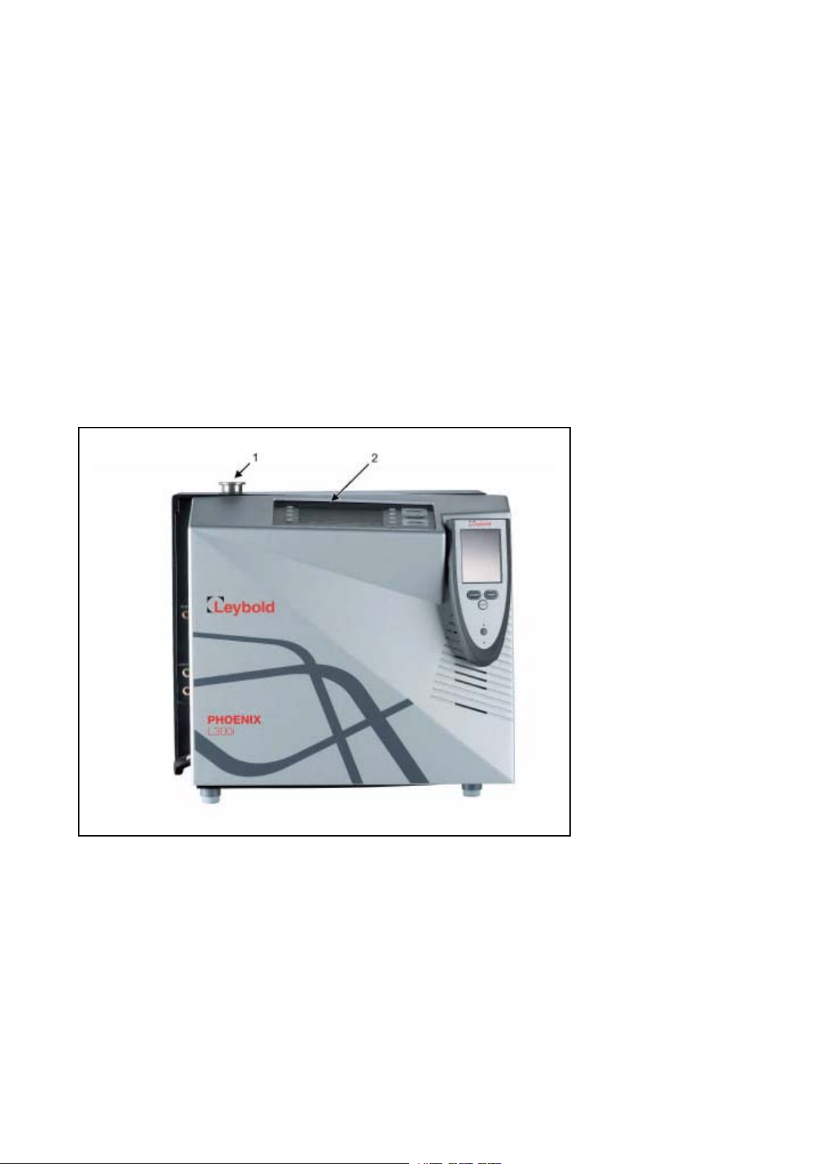
Fig. 1 View of the PHOENIX L300i
1 inlet flange 2 control panel
1.1 Design and Function
The PHOENIX L300i basically is a helium leak detector for vacuum applications, i.e.
the part under test is evacuated while the test is performed. The vacuum is achie
ved with a pumping system that is part of the PHOENIX L300i. In addition the
vacuum can be generated by pumps which are set up in parallel to the PHOENIX
L300i.
The PHOENIX L300i MODUL needs a fore vacuum pump, dry or wet version, to be
connected because this unit has no internal roughing pump. The connection
(DN25 KF) is on the side or under the bottom of the PHOENIX L300i MODUL (
7).
GA10218_002_C0 - 10/2016 - © Leybold GmbH 9
-
Fig.
Page 10
Description
1
2
7
4
6
5
3
Another operating mode of the PHOENIX L300i is the Sniffer mode which can only
be used when a sniffer line (See Chapter
1.1.6) is hooked up.
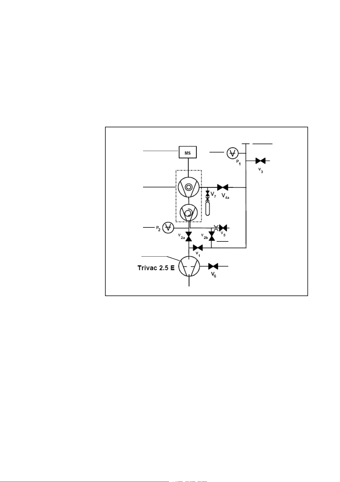
1.1.1 Vacuum Diagram PHOENIX L300i
The vacuum diagram below shows the major components inside the PHOENIX
L300i.
Fig. 2 Vacuum diagram PHOENIX L300i
Pos. Description
1 MS: Mass Spectrometer, Helium sensor (180° magnetic field mass
spectrometer)
2 Turbo molecular pump (TMP, provides high vacuum conditions in the MS)
3 Pirani gauge P2 (fore vacuum pressure)
4 Fore pressure pump (provides the fore vacuum pressure for the TMP and
pumps down the parts under test)
5 Inlet Port
6 Pirani gauge P1 (inlet pressure)
V1 … V7: Electromagnetic Valves to control the gas flows
The mass spectrometer (MS) is mainly composed of the ion source with cathode,
the magnetic separator and the ion collector.
Gas molecules getting into the mass spectrometer are ionized by the ion source.
These positively charged particles are accelerated into the magnetic field following
a circular path, the radius of which depends on the mass-to-charge ratio of the
ions. When mass 4 is selected (Default setting) only helium ions can pass this filter
and reach the ion collector where the stream of the ions is measured as an
electrical current. When selected another mass than 4, only the corresponding ions
GA10218_002_C0 - 10/2016 - © Leybold GmbH
10
Page 11
can pass the filter.
MS
P
1
V
1
V
2a
V
3
V
2b
P
2
V
V
4 a
4 b
V
6
V
5
V
7
1
2
3
6
5
4
Diaphragm pump
For operation the mass spectrometer requires a vacuum level in the range of 1·10
4
mbar and lower. This pressure is provided by the turbo molecular pump which in
turn is backed up by a fore vacuum pump.
Besides maintaining the pressure in the mass spectrometer the pump system is
used to evacuate the test parts. It is made sure that the pressure in the mass
spectrometer is low enough under all circumstances. The valves V1, V2a, V2b, V4a
control the gas flows when measuring. Valves V3 and V5 are used to vent the sys
tem and the Turbo pump, valve V6 controls the gas ballast function of the fore
vacuum pump. Valve V7 opens and closes the internal test leak during calibration.
With the pressure in the test part being lower than ambient pressure sprayed
helium (or Hydrogen as forming gas) can penetrate into the part in case of a
leakage. As soon as the pressure conditions allow it one of the valves to the TMP
opens. Now Helium can penetrate into the mass spectrometer contrary to the
pumping direction of the TMP.
Description
-
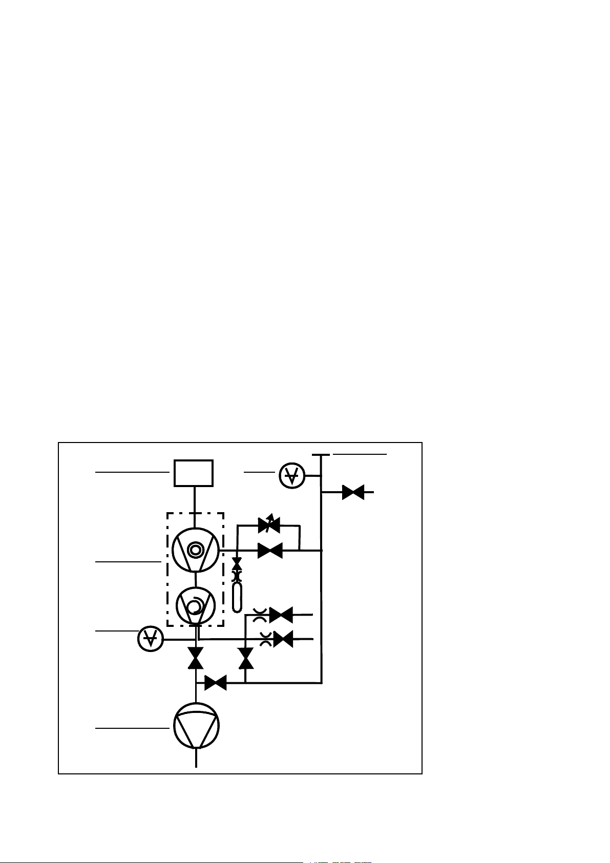
1.1.2 Vacuum Diagram PHOENIX L300i DRY
The PHOENIX L300i DRY has a diaphragm pump as fore vacuum pump, making it
suitable for applications where oil sealed systems can not be used. Furthermore
the PHOENIX L300i DRY contains one more valve, the valve 4b. This valve opens
step by step to regulate the inlet pressure into the turbo pump.
Fig. 3 Vacuum diagram PHOENIX L300i DRY
GA10218_002_C0 - 10/2016 - © Leybold GmbH 11
Page 12
Description
MS
P
1
V
1
V
2a
V
3
V
2b
V
6
P
2
V
4a
external pump
V
5
V
7
1
2
4
5
3
6
Pos. Description
1 MS: Mass Spectrometer, Helium sensor (180° magnetic field mass
spectrometer)
2 Turbo molecular pump (TMP, provides high vacuum conditions in
the MS)
3 Pirani gauge P2 (fore vacuum pressure)
4 Diaphragm pump (provides the fore vacuum pressure for the TMP
and pumps down the parts under test)
5 Inlet Port
6 Pirani gauge P1 (inlet pressure)
V1 … V7: Electromagnetic Valves to control the gas flows
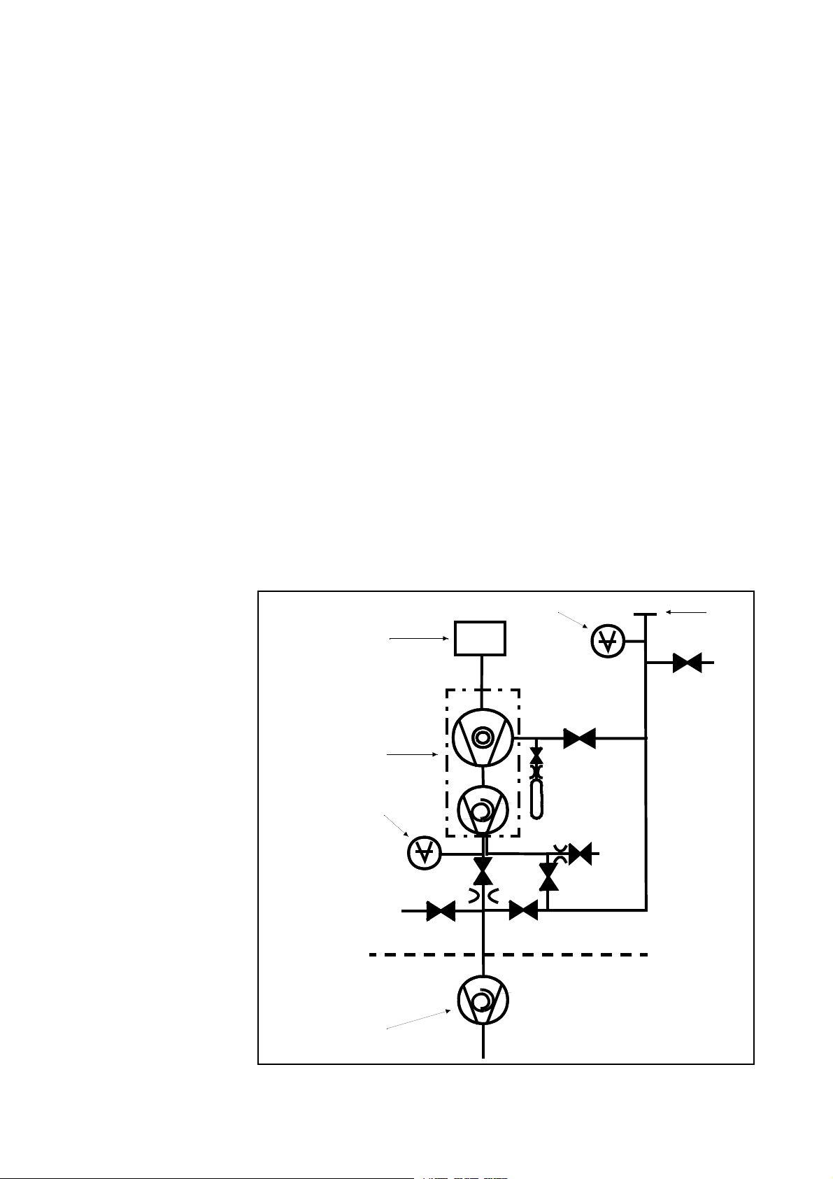
1.1.3 Vacuum Diagram PHOENIX L300i MODUL
The PHOENIX L300i MODUL has no roughing pump integrated as the other
models. Therefore it can be used with an external pump only. This pump can be oil
3
sealed or a dry version with a roughing capacity between 2.5 and 65 m
/h. This
pump has to be connected to the DN25 KF at the side or under the bottom of the
PHOENIX L300i MODUL.
Fig. 4 Vacuum diagram PHOENIX L300i MODUL
GA10218_002_C0 - 10/2016 - © Leybold GmbH
12
Page 13

Pos. Description
1 MS: Mass Spectrometer, Helium sensor (180° magnetic field mass
spectrometer)
2 Turbo molecular pump (TMP, provides high vacuum conditions in
the MS)
3 Pirani gauge P2 (fore vacuum pressure)
4 Fore pressure pump (provides the fore vacuum pressure for the
TMP and pumps down the parts under test)
5 Inlet Port
6 Pirani gauge P1 (inlet pressure)
V1 … V7: Electromagnetic Valves to control the gas flows
1.1.4 Vacuum Method
For the purpose of leak detection on a test sample (vacuum method), the sample
has to be evacuated so that Helium or Hydrogen which is sprayed on to the out
side, can enter through any leaks due to the pressure differential for detection by
the PHOENIX L300i.
Description
-
The test sample is evacuated - START button (Fig 16./10) - by the backing pump
or the external pump. In the case of larger test samples an additional external par
tial flow pump with a corresponding linking valve may be connected in parallel as
required.
Inlet valve V1 is opened so that the evacuation can take place. At the same time all
other valves are closed in order to prevent an unacceptable pressure increase in
the mass spectrometer.
In this context (valve V2a closed) the turbo molecular pump is operated without
being supported by the rotary vane pump. Since generally no gas is pumped out of
the mass spectrometer, p
The condition for the evacuation process described here is maintained until the
inlet pressure p1 has dropped <15
additionally. Possibly present Helium or Hydrogen may now flow upstream against
the pumping direction of the turbo molecular pump into the mass spectrometer
where it is detected. This measurement mode is called GROSS. In this mode, leak
rates down to 10
Since the rotary vane vacuum pump continues to evacuate the test sample via valves V2a, V2b and V1 the inlet pressure p1 will continue to drop. When the pressure
drops below p
valve V1and V2b closes and valve V4a opens so that the gas flow enters the turbo
molecular pump at the side. This offer two advantages:
-8
mbar l/s can be detected.
< 0.2 mbar, the PHOENIX L300i will switch to the FINE mode, i.e.
1
remains constant or increases only slowly.
2
mbar. Now the valves V2a and V2b are opened
-
a) A part of the high pumping speed of the turbo molecular pump
remains available for further evacuation of the test sample. The res
ponse time is inversely proportional to pumping speed.).
b) The advantages offered by the counter flow principle can still be utili-
zed
In the FINE mode the full sensitivity of the PHOENIX L300i is reached.
Because of the higher base pressure of the diaphragm pump the switching from
GROSS to FINE mode of the PHOENIX L300i DRY is done by the valve V4b. When
the pressure drops below 3,5
mbar the valves V1 and V2b will be close and V4b
GA10218_002_C0 - 10/2016 - © Leybold GmbH 13
-
Page 14

Description
opens step by step. When valve V4b is open completely, pressure < 0,1 mbar, V4a
will open also to get the maximum pumping speed. In PRECISION mode the PHO
ENIX L300i DRY opens the valve V4b only, with the disadvantage of low pumping
speed but with the highest sensitivity.
When the leak detection process is stopped – STOP-button – all valves except
valve V2a are closed.
Valve V3 is opened during venting of the inlet or test sample.
1.1.5 Partial Flow Method
In the partial flow mode the test sample is additionally evacuated by an auxiliary
pump. Using the optional partial flow pump set offers to the user the following
advantages (PHOENIX L300i
- faster response time
- entry into the measure mode already at an inlet pressure of 1000 mbar
- faster venting of large test objects
and PHOENIX L300i MODUL:
-
Alternatively to a partial flow pump set an external auxiliary pump may also be connected via a tee, this option is possible for the PHOENIX L300i dry and PHOENIX
L300i MODUL also. However, in such a case the PHOENIX L300i will not be able to
make measurements already at an inlet pressure of 1000
1.1.6 Sniffer Mode
The PHOENIX L300i may simply be converted into a sniffer leak detector via the
rugged sniffer line (Cat. No. 252003)
For this the KF flange of the sniffer line is connected to the inlet flange (Fig. 1/1) and
the sniffer mode is selected through menu mode. After pressing START, the inlet
valve V1 (
PHOENIX L300i is operated in the FINE mode. If the fore vacuum pressure P2 increases over 0,2 mbar respectively 0,1 mbar a warning sign and audio alarm comes
up in the display
In the measurement mode the helium present in the ambient air is now indicated as
the leak rate (about 2
the ZERO-button. In sniffer mode the smallest detectable leak rate is < 1· 10
mbarl/s.
1.2 Supplied Equipment
The PHOENIX L300i will be shipped in a special cardboard packed separately in a
plastic foil as protection against dust.
Supplied equipment includes:
Fig. 2) opens. The sniffer lines have been designed in such a way that the
· 10-6 mbar l/s). Smaller leaks may be detected by pressing
mbar.
-7
Leak Detector PHOENIX L300i
Set of fuses
Power cord
Folder with documents (Operating instructions, Spare part list)
2 L-type screwed connections (hose connections)
1 hose nozzle
Blank flange DN 25 KF
Clamping ring DN 25 KF
Centering ring DN 25 KF
GA10218_002_C0 - 10/2016 - © Leybold GmbH
14
Page 15

1.3 Technical Data
1.3.1 Technical Data PHOENIX L300i
Physical data
Max. inlet pressure 15 mbar
Minimum detectable Helium leak rates
- in vacuum mode
- in sniffer mode
Minimum detectable Hydrogen leak rates
- in vacuum mode
- in sniffer mode
Maximum Helium leak rate which can be displayed 0.1 mbar l / s
Measurement range 12 decades
Time constant of the leak rate signal (blanked off,
63% of the final value)
Pumping speed (Helium) at the inlet
- GROSS mode 0.4 l/s
- FINE mode > 2.5 l/s
Detectable masses 2, 3 and 4
Mass spectrometer 180° magnetic sector
Ion source 2 filaments;
Inlet port DN 25 KF
Run-up time (after starting) < 2 min
To get down to the minimum detected leak rate range some conditions must be
fulfilled:
-12
<5·10
<1·10-7 mbar l / s
<1·10-8 mbar l / s
<1·10-7 mbar l / s
<1 s
field
Iridium/Yttrium-oxide
mbar l / s
Description
Physical data
PHOENIX L300i has to run at least 20 minutes
Ambient conditions must be stable (temperature, no vibration/accelerations.)
The part under test has been evacuated long enough without using the zero function (background is no longer decreasing)
ZERO must be active
GA10218_002_C0 - 10/2016 - © Leybold GmbH 15
Page 16

Description
Electrical data
Other data
Electrical data
Power supply Cat.-No.250000V01
Cat.-No.251000V01
Cat.-No.251100V01
Power consumption 420 VA
Type of protection IP40
Other data
Valves solenoid
Dimensions (L × W × H) in mm 495 x 456 x 314
Weight in kg 40.0
Noise level dB (A) < 54
max. Audio alarm dB (A) 90
Contamination level (to IEC 60664-1) 2
Overvoltage category (to IEC 60664-1) II
230 V, +/- 5%, 50/60 Hz
115 V, +/- 5%, 60 Hz
100 V, +/- 5%, 50/60 Hz
Ambient conditions
Ambient conditions
For use within buildings
Permissible ambient temperature (during operation) +10 °C … +40 °C
Permissible storage temperature -10 °C … +60 °C
Maximum relative humidity 80% (up to 31°C)
linear decreasing to
50% at 40°C
Max. permissible height above sea level
(during operation)
2000 m
GA10218_002_C0 - 10/2016 - © Leybold GmbH
16
Page 17

Description
1.3.2 Technical Data PHOENIX L300i DRY
Physical data
Max. inlet pressure 15 mbar
Minimum detectable Helium leak rates
- in vacuum mode
- in sniffer mode
Minimum detectable Hydrogen leak rates
- in vacuum mode
- in sniffer mode
Maximum Helium leak rate which can be displayed 0.1 mbar l / s
Measurement range 11 decades
Time constant of the leak rate signal (blanked off,
63% of the final value)
Pumping speed (Helium) at the inlet
GROSS mode 0.02 l / s
PRECISION mode 0,4 l / s
FINE mode > 2.5 l / s
Detectable masses 2, 3 and 4
Mass spectrometer 180° magnetic sector
Ion source 2 filaments;
Inlet port DN 25 KF
Run-up time (after starting) < 2 min
-11
< 3·10
< 1·10-7 mbar l / s
< 1·10-8 mbar l / s
< 1·10-7 mbar l / s
<1 s
field
Iridium/Yttrium-oxide
mbar l / s
Physical data
To get down to the minimum detected leak rate range some conditions must be
fulfilled:
PHOENIX L300i has to run at least 20 minutes
Ambient conditions must be stable (temperature, no vibration/accelerations.)
The part under test has been evacuated long enough without using the zero function (background is no longer decreasing)
ZERO must be active
GA10218_002_C0 - 10/2016 - © Leybold GmbH 17
Page 18

Description
Electrical data
Other data
Electrical data
Power supply Cat.-No.250001V01
Cat.-No.251001V01
Cat.-No.251101V01
Power consumption 350 VA
Type of protection IP40
Other data
Valves solenoid
Dimensions (L × W × H) in mm 495 x 456 x 314
Weight in kg 35.5
Noise level dB (A) < 54
max. Audio alarm dB (A) 90
Contamination level (to IEC 60664-1) 2
Overvoltage category (to IEC 60664-1) II
230 V, 50 Hz
115 V, 60 Hz
100 V, 50/60 Hz
Ambient conditions
Ambient conditions
For use within buildings
Permissible ambient temperature (during operation) +10 °C … +40 °C
Permissible storage temperature -10 °C … +60 °C
Maximum relative humidity 80% (up to 31°C)
linear decreasing to
50% at 40°C
Maximum permissible height above sea level
(during operation)
2000 m
GA10218_002_C0 - 10/2016 - © Leybold GmbH
18
Page 19

Description
1.3.3 Technical Data PHOENIX L300i MODUL
Physical data
Max. inlet pressure 15 mbar
Minimum detectable Helium leak rates
in vacuum mode
- with Scroll pump
- with oil sealed pump
in sniffer mode
Minimum detectable Hydrogen leak rates
- in vacuum mode
- in sniffer mode
Maximum Helium leak rate which can be displayed 0.1 mbar l / s
Measurement range 12 decades
Time constant of the leak rate signal (blanked off,
63% of the final value)
Pumping speed (Helium) at the inlet
GROSS mode 1,0 l / s
FINE mode > 2.5 l / s
Detectable masses 2, 3 and 4
Mass spectrometer 180° magnetic sector
Ion source 2 filaments;
Inlet port DN 25 KF
Run-up time (after starting) < 2 min
-12
< 8·10
< 5·10
<1·10-7 mbar l / s
< 1·10-8 mbar l / s
< 1·10-7 mbar l / s
< 1 s
field
Iridium/Yttrium-oxide
mbar l / s
-12
mbar l / s
Physical data
To get down to the minimum detected leak rate range some conditions must be
fulfilled:
PHOENIX L300i has to run at least 20 minutes
Ambient conditions must be stable (temperature, no vibration/accelerations.)
The part under test has been evacuated long enough without using the zero function (background is no longer decreasing)
ZERO must be active
GA10218_002_C0 - 10/2016 - © Leybold GmbH 19
Page 20

Description
Electrical data
Other data
Ambient conditions
Electrical data
Power supply Cat. No. 250002V01 100 - 240 V
50/60 Hz
Power consumption 200 VA
Type of protection IP40
Power cords (EU, USA, UK) 2.5 m
Other data
Valves solenoid
Dimensions (L × W × H) in mm 495 x 456 x 314
Weight in kg 35.5
Noise level dB (A) < 54
max. Audio alarm dB (A) 90
Contamination level (to IEC 60664-1) 2
Overvoltage category (to IEC 60664-1) II
Ambient conditions
For use within buildings
Permissible ambient temperature (during operation) +10 °C … +40 °C
Permissible storage temperature -10 °C … +60 °C
Maximum relative humidity 80% (up to 31°C)
linear decreasing to
50% at 40°C
Maximum permissible height above sea level
(during operation)
2000 m
GA10218_002_C0 - 10/2016 - © Leybold GmbH
20
Page 21
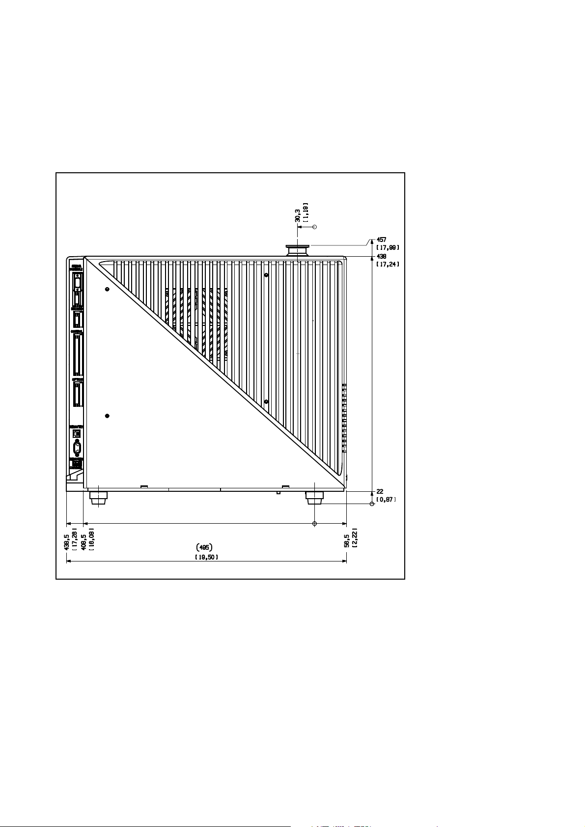
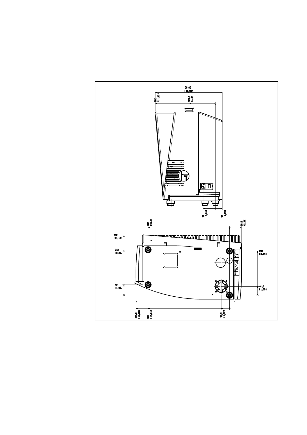
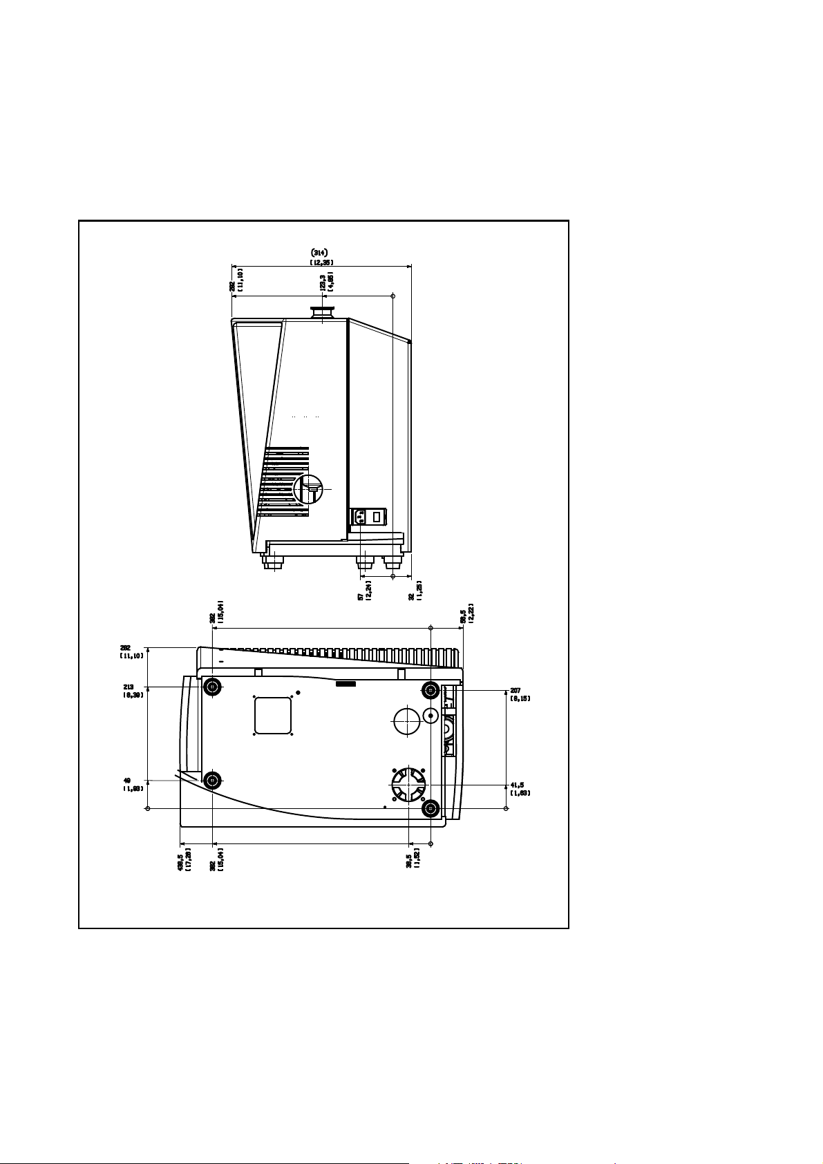
1.3.4 Dimensional Drawings
Abmaße PHOENIX L300i Familie in mm und inch. (in Klammern)
Dimensions PHOENIX L300i family in mm and inches (in brackets).
Description
Fig. 5 Dimensions PHOENIX L300i
GA10218_002_C0 - 10/2016 - © Leybold GmbH 21
Page 22
Description
Abmessungen PHOENIX L300i Familie
in mm und inch. (in Klammern)
Dimensions family inPHOENIX L300i
mm and inches (in brackets)
GA10218_002_C0 - 10/2016 - © Leybold GmbH
22
Fig. 6 Dimensions PHOENIX L300i side view
Page 23
Description
Abmessungen
PHOENIX L300i in mm
und inch (in Klammern).
Dimensions PHOENIX L300i
in mm and inches (in brackets).
Fig. 7 Dimensions PHOENIX L300i MODUL
GA10218_002_C0 - 10/2016 - © Leybold GmbH 23
Page 24

Description
1.4 Ordering Information
PHOENIX L300i EU-Version 250000V01
PHOENIX L300i DRY EU-Version 250001V01
PHOENIX L300i MODUL 250002V01
PHOENIX L300i US-Version 251000V01
PHOENIX L300i DRY US-Version
PHOENIX L300i JP-Version 251100V01
PHOENIX L300i JP-Version 251101V01
1.5 Accessories
The following parts can be ordered additionally:
251001V01
Sniffer line SL300 252003
Sniffer line SL301, 4 m 252025V01
Sniffer line SL301, 10 m 252026V01
Leak Ware (Software for data acquisition) 14090
Helium Sniffer QUICK-TEST Qt 100 15594
Remote control set RC310C consisting of:
- Remote control
- cable 4 m
- mounting parts
Extension cable for remote control,10m
Remote control set RC310WL wireless
consisting of:
- Remote control
- Radio transmitter
- mounting parts
Radio transmitter for remote control 252015V01
Spray gun with hose 16555
Set of connection plugs 20099024
Partial flow system (PHOENIX L300i and PHOENIX
L300i MODUL)
Adapter USB/RS232 800110V0103
252013V01
14022
252014V01
14020
GA10218_002_C0 - 10/2016 - © Leybold GmbH
24
Page 25
Sniffer line
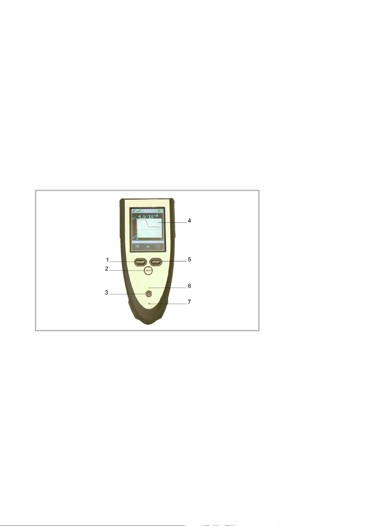
With the use of a sniffer line the PHOENIX L300i can easily be converted to a sniffer
leak detector.
Available versions:
SL300: 4 m
SL301: 4 m and 10 m
For further information on the sniffer lines SL300 and SL301 see the enclosed
manuals.
Remote Control RC310WL Wireless and RC310C Wired
Description
Sniffer line
Remote control
Fig. 8 Remote Control RC310WL wireless
For further information on the remote controls RC310WL and RC310C see instruction manual with the document number 300306406_002_A1.
Partial Flow System (PHOENIX L300i and PHOENIX L300i
In the partial flow mode the test sample is additionally evacuated by an auxiliary
pump. Using the optional partial flow pump set offers to the user the following
advantages:
- faster response time
- entry into the measurement mode already at an inlet pressure of 1000 mbar
- faster venting of large test objects
The partial flow system consists of the components partial flow valve block, right
angle valve DN 25 KF, control cable and vacuum hose with flange connections.
The partial flow valve block with the right angle valve has to be connected to the
inlet flange of the PHOENIX L300i. Connect the control cable to the Option port
and the vacuum hose to the auxiliary pump. The PHOENIX L300i has to be
configurated as described in chapter.
For further detailed information please refer to operating instructions GA 10.277
partial flow system.
GA10218_002_C0 - 10/2016 - © Leybold GmbH 25
Partial flow system
Page 26

Description
1.6 Default Settings
The following parameters are set like shown when in the menu of the PHOENIX
L300i under Settings > Parameters, Load / Save is chosen.
Scale linear
Display range: 4 decades
Time axis: 32 seconds
LCD inverted off
Background in standby mode: off
Calibration request: off
Mass: 4 (helium)
Recorder: leak rate
Volume: 2
Leak rate unit: mbar l/s
Mode: Vacuum
Trigger level 1: 1E-9 mbar l/s
Trigger level 2: 1E-8 mbar l/s
Trigger level 3: 1E-7 mbar l/s
Leak rate external test leak (vacuum): 1E-7 mbar l/s
Leak rate external test leak (sniffer): 1E-5 mbar l/s
Vent delay: 2 seconds
Automatic purge (PHOENIX L300i DRY
and PHOENIX L300i MODUL only)
Pressure: mbar
Minimum volume: 0
Beep: on
Maximum evacuation time: 30 minutes
Audio Alarm Type: Trigger Alarm
Max. pressure limit for sniff mode 0.15 mbar
Min. pressure limit for sniff mode 0.05 mbar
Control location local
Alarm delay: 30 seconds
Leak rate filter: auto
Zero: enable
Vacuum ranges normal
Upper display limit 1E-5 mbar l/s
Service message exhaust oil filter
(PHOENIX L300i only)
Contamination protection Off
Switch-off limit for contamination protection:
(Limits: 1E-6 mbar*l/s … 1E+3 mbar*l/s)
on
on
1E-3 mbar*l/s
GA10218_002_C0 - 10/2016 - © Leybold GmbH
26
Page 27

2 Installation
2.1 Placement
Unpack the PHOENIX L300i immediately after delivery, even if it will be installed
later on.
Examine the shipping container for any external damage. Completely remove the
packaging materials.
Check the PHOENIX L300i is complete (see Chapter Supplied Equipment) and
carefully examine the PHOENIX L300i visually.
If any damage is discovered, report it immediately to the forwarding agent and
insurer. If the damaged part has to be replaced, please contact the orders depart
ment.
Retain the packaging materials in the case of complaints about damage.
2.2 Conforming Utilisation
The PHOENIX L300i is a leak detector for Helium or Hydrogen. This instrument
may be used to detect the location and the size of leaks on objects under test in
two different ways:
-
Installation
when the test sample has been evacuated first and is sprayed with helium on the
outside. It is required that a vacuum connection is provided between the PHOENIX
L300i and the test sample (vacuum mode).
or
when a helium overpressure is provided in the test sample and the test sample is
searched from the outside with a sniffer probe which is attached to the inlet port
(sniffer mode).
The PHOENIX L300i is to be used for leak detection only. It must not be used as a
pumping system (esp. pumping aggressive or humid gases.)
The leak detector is not suitable for
- pumping liquids or gases containing dust or particles
- pumping corrosive or reactive gases
2.3 Ambient Conditions
The permissible ambient temperature is between +10°C (50°F) and +40°C (104°F).
The PHOENIX L300i must not be operated in explosive gas atmospheres.
Make sure to avoid dripping water.
Ensure a sufficient air cooling.
Ambient temperatures
2.4 Electrical Connections
2.4.1 Mains Power
Generally the local regulations for electrical connections must be observed.
Before connecting the PHOENIX L300i to the mains you must make sure that the
mains voltage rating of the PHOENIX L300i coincides with the locally available
mains voltage. The instrument must exclusively be connected to a single phase
supply with fuses for installation (Circuit breaker 10A max. according to IEC/EN
60898 with tripping characteristic B).
GA10218_002_C0 - 10/2016 - © Leybold GmbH 27
Warning
Page 28
Installation
1
2
3
4
5
9
7
11
8
12
6
10
Only 3-core mains cables having a protection ground conductor must be used.
Operation of the PHOENIX L300i where the ground conductor has been left uncon
nected is not permissible. The PHOENIX L300i can be damaged when using the
wrong voltage. The voltage must be in the range 230V (+/- 5%), 115V (+/- 5%) or
100V (+/- 5%) depending on the version.
The mains voltage rating for the PHOENIX L300i can be read off from the name
plate beneath the mains socket
not be changed.
A separate fuse for each of the mains conductors has been integrated into the
mains switch.
The mains voltage is applied to the instrument via the detachable mains cable
which is supplied with the instrument. A mains socket
purpose at the side of the instrument.
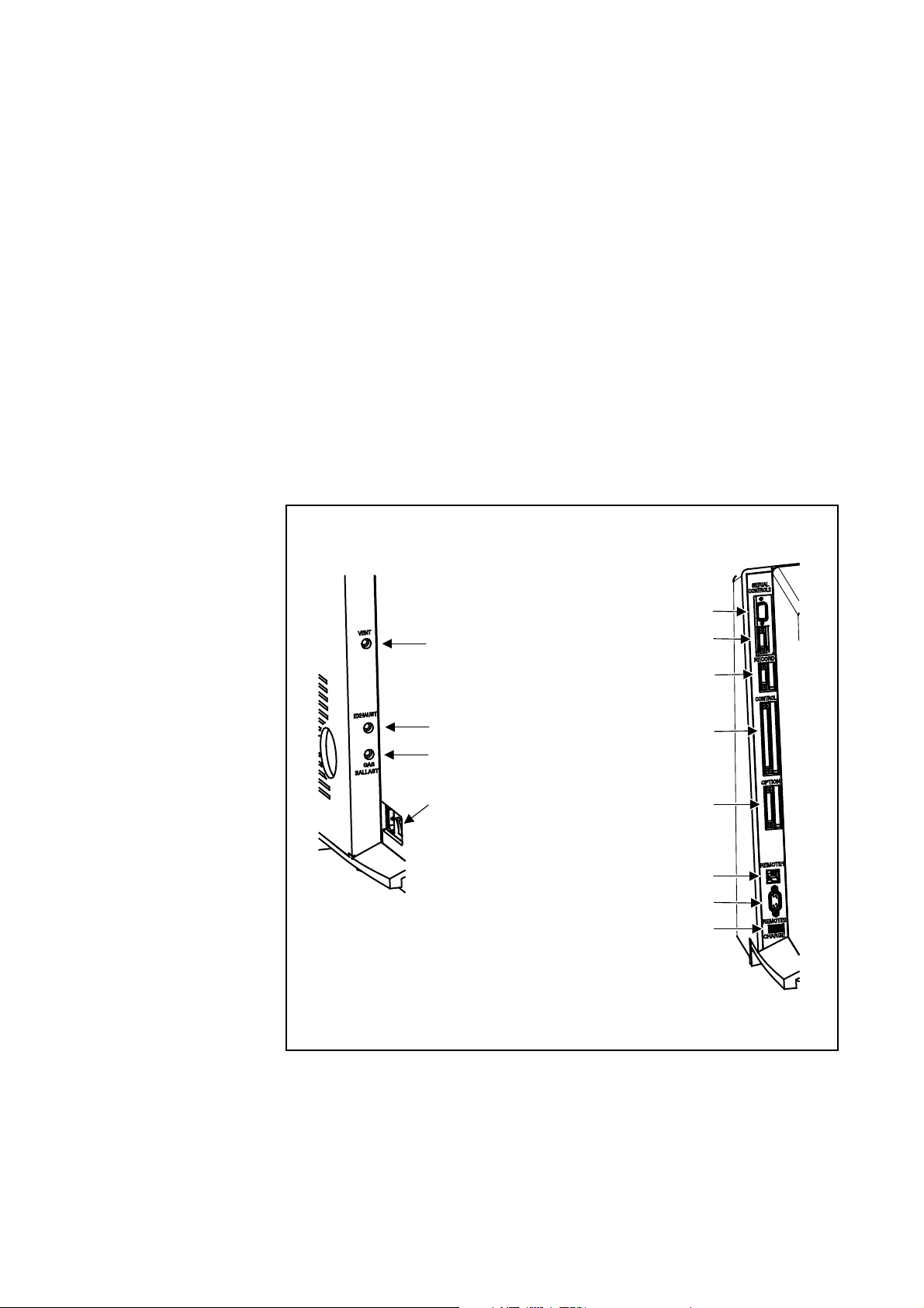
Fig. 9/4 at the side. This voltage is fixed and can
Fig. 9/4 is available for this
-
Left side:
1. VENT
2. EXHAUST
3. GASBALLAST
4. On / Off switch, mains
socket
Right side:
5. SERIAL
6. CONTROL2
7. RECORD
8. CONTROL
9. OPTION
10. REMOTE1
11. REMOTE2
12. CHARGE (iPad)
28
GA10218_002_C0 - 10/2016 - © Leybold GmbH
Fig. 9 Side views of the PHOENIX L300i
Page 29

2.4.2 Connection for the Controller Signal and Accessories
Installation
Option (Accessories)
The sniffer line SL300 or the partial flow system may be connected to the option
port (
Fig. 9/9):
Contact pins 1 and 3 are fused together with a 0.8 A slow-blow fuse. The amount
of power which can be drawn is limited to 10 W.
The contacts are numbered from bottom to top.
Pin Assignment
1 +24 V, constantly applied, power supply for the Leybold
partial flow valve or sniffer line.
2 GND
3, +24V switched by the PHOENIX L300i for an external
venting valve
4, 5, 6, 7, 8 These pins are used in connection with accessories.
Digital Out (CONTROL)
The following relay outputs Fig. 9/8 are available for further signal processing. The
maximum rating for the relay contacts is 60V AC/1A.
All pins of digital I/O, digital out and recorder must not be connected with
voltages higher than 60V DC/25V AC (to grounding equipment conductor) or
reach this threshold.
OPTION
Digital out (CONTROL)
Caution
The contacts are numbered from bottom to top.
Pin Assignment
1 PLC in free selectable
2 PLC in free selectable
3 PLC in free selectable
4 GND
5 to 7 Digital out free selectable, 5 center contact, 6 normally open
contact, 7 normally closed contact
8 to 10 Digital out free selectable
11 to 13 Digital out free selectable
14 to 16 Digital out free selectable
The pin assignment for contacts 8 to 16 follows the same order as for pins 5 to 7.
For further information see chapter Interfaces.
GA10218_002_C0 - 10/2016 - © Leybold GmbH 29
Page 30

Installation
Digital In (CONTROL2)
Caution
Digital In (Control 2)
These inputs can be used to control the PHOENIX L300i with a programmable
logic control (PLC).
The contacts are numbered from bottom to top.
Maximum input voltage 35V.
Pin Assignment
1 PLC in free selectable
2 PLC in free selectable
3 PLC in free selectable
4 PLC GND
These inputs Fig. 9/6 are working only, if the correct location of control is chosen.
See chapter Interfaces.
To avoid a mistake between the connection Control 2 and Record, pin 1 and 4 are
blocked. When using the connectors the guiding nose for pin 1 and 4 must be
removed.
Recorder/RECORD
Recorder/RECORD
The recorder output Fig. 9/7 may be used to chart the leak rate, the inlet pressure
and the fore vacuum pressure. Both recorder activities can be adjusted individually
for showing leak rates and pressures.
The measured values are provided by way of an analogue signal in the range of 0 V
… 10
V. The resolution is limited to 10 mV. The instrument which is connected to
the recorder output (e. g. X(t) chart recorder) should have an input resistance of no
less than 2.5
reference potential (GND) is available at pins 2 and 3.
The contacts are numbered from bottom to top.
The chart recorder outputs are electrically isolated from other plugs. If, in spite of
this, hum interference is apparent it is recommended to operate the PHOENIX
L300i and the chart recorder from the same mains phase. If this is not possible,
you must make sure that the frame ground of both instruments is kept at the same
potential.
Pin Assignment
1 Analog 1, leak rate, inlet pressure P1 or fore vacuum pressure P2
2 GND
3 GND
kW. The measured values are available through pins 1 and 4. The
4 Analog 2, leak rate, inlet pressure P1 or fore vacuum pressure P2
For further information see chapter Interfaces.
GA10218_002_C0 - 10/2016 - © Leybold GmbH
30
Page 31

Installation
SERIAL/RS232
This RS232 interface Fig. 9/5 is wired as data communication equipment (DCE)
and permits the connection of a personal computer (PC) for monitoring and data
logging. The connection is made through a 9
tion refer to chapter Interfaces and the Interface Description.
Pin Assignment
1 24 V switchable, default setting 0
2 TXD
3 RXD
4 GND 24V
5 GND
6 DSR
7 CTS
8 RTS
9 free
pin sub-D socket. For more informa-
SERIAL/RS 232
Remote Control (REMOTE1)
The remote control interface Fig. 9/10 is a serial interface to control the PHOENIX
L300i by the remote control. The remote control can be connected via an extension cable with a RJ45 plug. Refer to the Interface Description for more information. The remote control does not belong to the standard equipment. If the remote
control is connected via a cable, wireless communication over REMOTE2 is exclu
ded.
Pin
2 +24V (fuse 0.8 A time lag)
3 0 V
4 RXD (intern. RS232)
5 TXD (intern. RS232)
REMOTE2
Through this interface the PHOENIX L300i is controlled wirelessly via Bluetooth or
WLAN. The Bluetooth transmitter connects to the remote control RC310 WL. The
WLAN module provides the connection to Apple I-Pad or other handheld devices.
Is the remote control RC310 WL connected via a cable to REMOTE1 REMOTE2
can not be used. The Bluetooth transmitter and the WLAN module are not included
PHOENIX L300i delivery.
Assignment
Remote control
REMOTE1
-
Remote control
REMOTE2
GA10218_002_C0 - 10/2016 - © Leybold GmbH 31
Page 32

Installation
Pin Assignment
1 free
2 RxD
3 TxD
4 connected to pins 6 and 7
5 GND
6 connected to pins 4 and 7
7 connected to pins 4 and 6
8 free
9 7.5V
CHARGE
Inlet port
Exhaust
CHARGE
The USB interface can be charged an Apple iPad only. The USB port does not
allow data exchange.
2.4.3 Vacuum Connections
Inlet Port
The inlet port is located on the top of the PHOENIX L300i Fig. 1/1. The size of the
flange is DN 25 KF.
A test object or a test chamber has to be connected to the inlet port if the vacuum
mode is chosen (See Chapter
The inlet port is also used for the connection of the sniffer line.
Exhaust
The exhaust Fig. 9/2 flange is located on the side of the PHOENIX L300i.
There is a filter mounted in the exhaust that absorbs the oil steams occur i ng
during the use of the rotary vane pump. The exhaust filter has to be cleaned when
doing the maintenance (see Chapter.
When the PHOENIX L300i is running in closed rooms the exhaust has to be put
out-of-doors using the provided adapter. So the oil steams that are harmful to
health are lead off.
With the provided connection a hose line can be connected to the exhaust of the
PHOENIX L300i and lead off.
Mode).
Exhaust Oil Filter).
Vent
Gas ballast connection
GA10218_002_C0 - 10/2016 - © Leybold GmbH
32
Vent
Usually the parts under test are vented with ambient air when the test is finished. If
it is required the parts can be vented with a different gas (i. e. fresh air, dry air, nitro
gen, …) at atmospheric pressure. In this case a vent hose has to be connected to
the hose coupling
mbar.
Gas ballast connection
For the mode gas ballast it is recommended to use helium-free gases at atmospheric pressure. Ambient air can be contaminated with helium due to spraying or
-
Fig. 9/1. The pressure in the venting line must nor exceed 1050
Page 33

charging. In this case a gas supply line (i. e. nitrogen, fresh air, …) should be connected to the hose coupling Fig. 9/3. The pressure of these gas line must not
exceed 1050 mbar.
The connectors 1,2 and 3 in Fig. 9 are quick connectors for hose diameters of 8/
6 mm.
Installation
Connection of an external pump (only PHOENIX L300i MODUL)
The PHOENIX L300i MODUL offers two possibilities to connect the external fore
vacuum pump to the DN 25 KF flange. One on the side of the PHOENIX L300i or
one in the bottom (measurements see
on the side is chosen. To change the connection proceed as follows:
1. Take of the mechanical hood, see chapter Opening of the PHOENIX L300i.
2. Loose the flange with the connection piece on the side of the PHOENIX L300i.
3. Disconnect the blind flange on the bottom, therefore lay the PHOENIX L300i
carefully on the electronic hood.
4. Screw in the connection piece into the flange in the bottom.
5. Connect the hose for the fore vacuum pump.
6. Connect the blind flange to the sidewise flange.
7. Put on the mechanical hood.
Fig. 5 - Fig. 7). As default setting the flange
Connection of external
pumps
GA10218_002_C0 - 10/2016 - © Leybold GmbH 33
Page 34

Operation
Purge gas/Gas ballast
3 Operation
3.1 Media Compatibility/Purge Gas
The PHOENIX L300i is a leak detector for helium and hydrogen. Only air and clean
gases must be used with the PHOENIX L300i.
The leak detector is not suitable for
- pumping liquids or gases containing dust
- pumping reactive or corrosive gases
As purge gas all gases can be used that
- does not contain helium
- are dry, clean and dust free
- generate no corrosion.
For venting or gas ballast a helium free gas at atmospheric pressure should be
used. Ambient air can be contaminated with helium due to spraying or charging, so
it is recommended to connect a hose to the vent- and fore vacuum port. The pres
sure in this hose must not exceed 1050 mbar.
3.2 Start-Up
The PHOENIX L300i is switched on by pushing the mains switch (Please refer to
Chapter
standby-mode and ready to measure.
2.4.1). After about 2 minutes the run-up procedure is finished; the unit is in
-
When using the PHOENIX L300i MODUL an additional fore vacuum pump (dry or
wet version) has to be connected to the fore vacuum connection (DN25 KF) on the
side or the bottom.
Please connect the part to be tested to the inlet port and press START. The PHOENIX L300i starts to evacuate the part. The evacuation time depends on the
volume of the test part. During evacuation the screen shows the inlet pressure
online.
Once the pressure of 15 mbar (11 Torr or 1500 Pa) is reached the unit switches to
measurement mode. The corresponding leak rate is displayed. For further explana
tions of the screen please refer to Chapter 3.2.5.
The displayed leak rate corresponds to the helium background concentration in the
part under test. Since the PHOENIX L300i continues to pump down the part this
background leak rate will further reduce. As soon as the leak rate is low enough in
respect to your requirements you may start spraying Helium or Hydrogen to search
for possible leaks.
When the measurement is finished please press STOP and hold the button a few
seconds to vent the part under test.
3.2.1 Display
The display is used to either show leak rates or program specific set-ups and get
information by means of the software menu (Please refer to Chapter
tion messages and maintenance instructions are displayed on the screen (Please
refer to Chapter
5).
3.6.1). In addi-
-
GA10218_002_C0 - 10/2016 - © Leybold GmbH
34
Page 35

3.2.2 The Display in Run-Up Mode
In run-up mode the display shows:
Speed of the turbomolecular pump
Fore-vacuum pressure
State of emission
Active filament
A bar graph which shows the run-up progress
If the display is too bright or too dark you can change the contrast. Please see
Chapter 3.4.6. During run-up phase the menu button can be pushed to get to the
selection menu.
Operation
3.2.3 The Display in Standby Mode
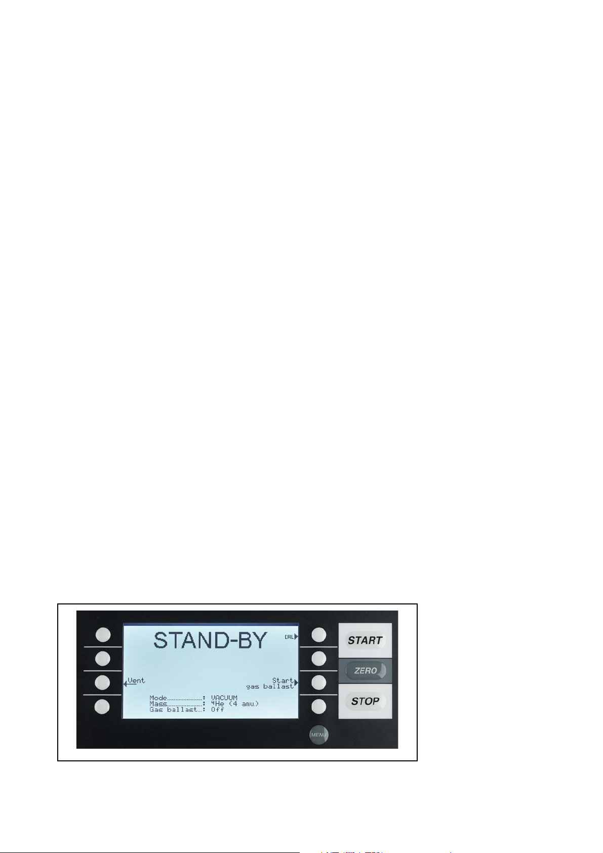
In standby mode the conditions are shown in the upper edge of the display (Fig.
12). Furthermore calibration (Please refer to Chapter 3.13) can also be started in
standby mode and purging, too (Fig. 1/1)
3.2.4 Gas Ballast/Purge
In standby mode the gas ballast of the forepump can be switched on/off manually
or via soft key 7. The gas ballast is for abolishing a too huge helium background.
Additionally a condensation of water vapor in the pump will be avoided. After 20
minutes the machine closes the gas ballast valve automatically to limit the loss of
oil.
This function can be chosen automatically for the PHOENIX L300i MODUL. Every
time the unit changes into standby mode the purge starts automatically for 20
seconds. During this time the scroll pump will be purged by the valve V6.
In case there was a large quantum of water vapor pumped with the machine
please activate the gas ballast for about 20 minutes before running the machine
down.
3.2.5 The Display in Measurement Mode
In measurement mode the leak rates can be displayed in two different modes:
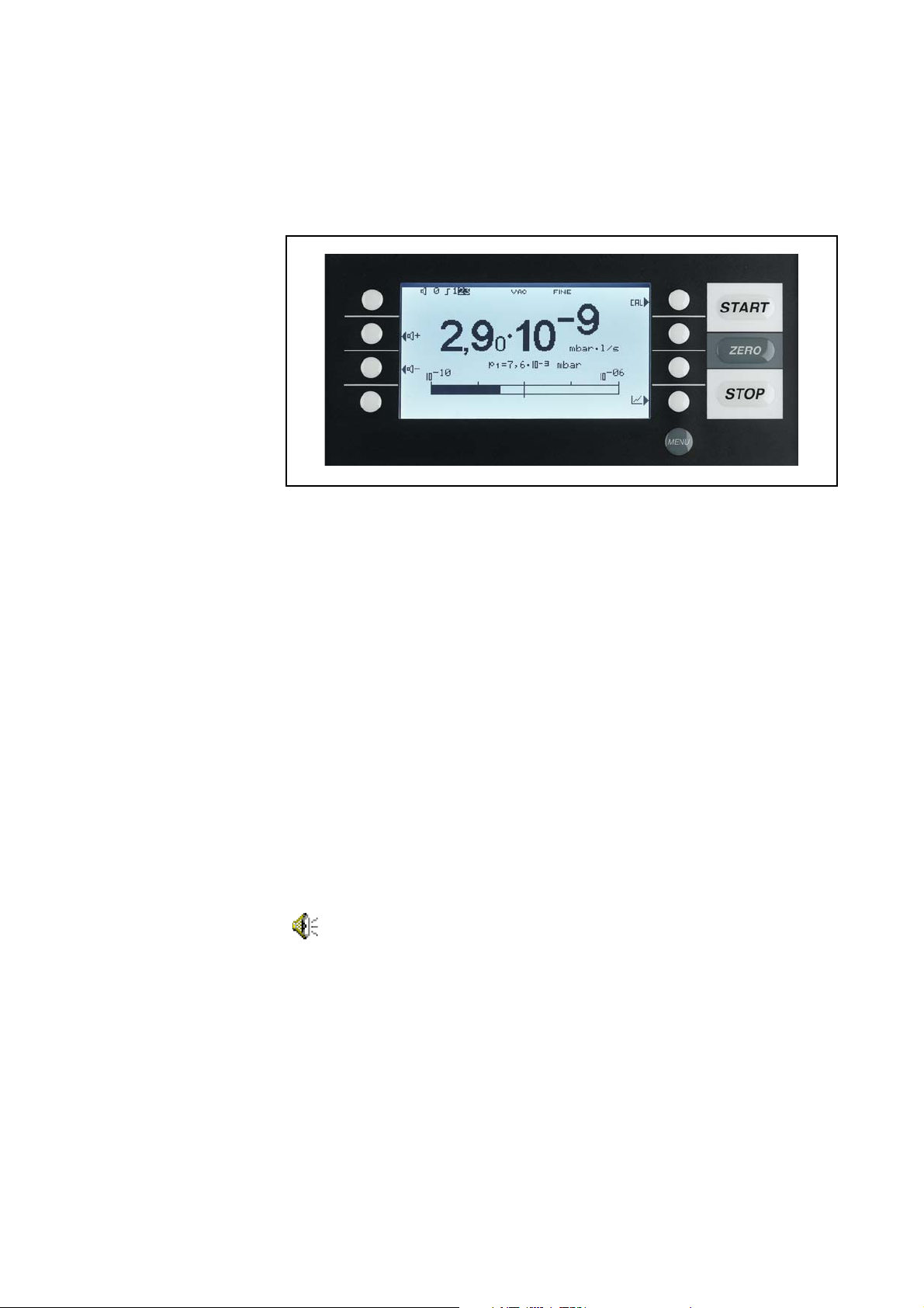
- Numerically, combined with a bargraph 10. Fig. 10.
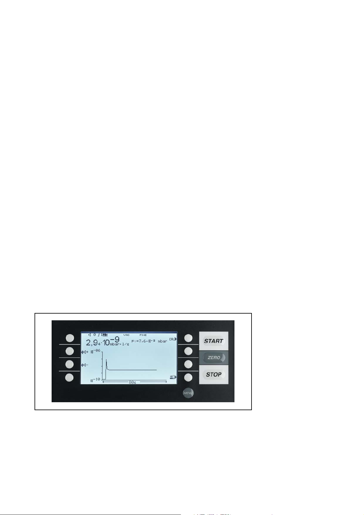
- As trend: numerically, combined with a diagram (leak rate versus time) Fig. 11.
In the lower right corner of the display (next to the Soft Key no. 8, Fig. 10 and Fig.
11) you will find a symbol that allows to switch between the display modes by pres-
sing Soft Key no. 8. See chapter 3.2.9 and 3.2.10 for explanations of the different
display modes.
Access to calibration (Soft Key no. 5, Fig. 10 and Fig. 11) and access to the
speaker volume (Soft Keys no. 2 and no. 3, Fig. 10 and Fig. 11) is the same in all
modes. Also the status icons in the upper line are in common in both display
modes.
GA10218_002_C0 - 10/2016 - © Leybold GmbH 35
Page 36
Operation
Fig. 10 Display: Measurement mode with bargraph
3.2.6 Call for Calibration
In all modes the soft key no.5 is used to get to the calibration routine. Refer to
Chapter.
3.2.7 Speaker Volume
On the left hand side two loud speaker symbols are shown, combined with the
signs + and - (
Keys no. 2 and no. 3) the volume can be adjusted for convenient loudness. In the
bottom line of the display another loud speaker symbol is shown, combined with a
number. This number indicates the level of the current loudness (ranges from 0 to
15).
Refer to Chapter 3.8 Volume for information on loudness, alarms, and sound
tracks.
3.13for further information regarding calibration.
Fig. 10 and Fig. 11). By pressing the corresponding soft keys (Soft
3.2.8 Status Line in the Display
The status line at the top of the display (Fig. 10 and Fig. 11) informs about (reading
from left to right):
Symbol of display Meaning Explanation
Volume level Please refer to Chapter 3.8
Speaker volume.
S1 Trigger 1 If the trigger values are
exceeded these signs are inver
ted. (White on black
background.)
S2 Trigger 2 see: Trigger 1
S3 Trigger 3 see: Trigger 1
! Warning triangle Please refer to Chapter 5
VAC Working mode VAC or SNIFF indicate which
working mode was selected
-
GA10218_002_C0 - 10/2016 - © Leybold GmbH
36
Page 37
Symbol of display Meaning Explanation
FINE Vacuum area Depending on the inlet pressure
the PHOENIX L300i may be in
GROSS, PRECISION (PHO
ENIX L300i DRY only) or FINE
mode, which is indicated here
(Chapter
ZERO ZERO Indicates if ZERO-function is
active.
3.10.1)
-
3.2.9 Measurement Mode with Bargraph
The display shows the leak rate in big digital figures, see Fig. 10. The unit of the
leak rate is shown, too. Underneath the leak rate the inlet pressure is displayed in
smaller digits. The units of leak rate and pressure can be defined in the menu (See
Chapter
3.8.4).
Operation
Below this the same leak rate is shown graphically as a bar. The scale of this bar,
i.e. the number of decades included in this bar can be defined in the menu (Please
refer to Chapter
3.8.1 and 3.8.2) are indicated at the bar by short vertical lines: a straight line for
trigger 1 and a dotted line for trigger 2.
3.6.4). The programmed trigger levels (Please refer to Chapters
3.2.10 Measurement Mode with Trend Information
In trend mode the leak rates are displayed over time Fig.11. In addition the actual
leak rate and inlet pressure also are displayed digitally. The time axis can be
defined in the menu (Please refer to Chapter
defined the same way as the bargraph (Please refer to Chapter 3.6.4).
3.6.5). The intensity axis (y-axis) is
Fig. 11 Display: Measurement mode with bargraph
3.3 First Operation Check
The steps for an initial operation are described here. It is explained how to switch
on the PHOENIX L300i, how to measure and how to carry out an internal calibra
tion.
If anything unexpected happens during the initial operation or the leak detector
acts in a strange way the PHOENIX L300i can be switched off by the mains switch
at any time.
GA10218_002_C0 - 10/2016 - © Leybold GmbH 37
First operation check
-
Page 38

Operation
Needed equipment
Startup and measure
Caution
Needed Equipment
The following parts will be needed:
A blind flange 25 KF (if not assembled at the inlet port).
A helium test leak with a DN 25 KF connection (optional).
A fore vacuum pump connected to the DN25 KF flange on the side or under the
bottom (dry or wet version) for use with the PHOENIX L300i MODUL
Startup and Measure
1. Unpack the PHOENIX L300i and inspect it for any external damage (refer to
Chapter
2. Connect the instrument to the mains power (refer to Chapter 2.4). For the PHO-
ENIX L300i MODUL connect the fore vacuum pump and switch it on.
3. Switch on the PHOENIX L300i by using the mains switch.
Don’t switch the PHOENIX L300i on when ambient temperature is below 10°C or
above 40°C
After power on a welcoming picture appears on the screen of the control panel Fig.
12, the status information on the speed of the turbo pump, the fore vacuum pres-
sure, the emission and the active filament are given.
The start up procedure takes less than 2 minutes and the end is indicated by a
signal. The PHOENIX L300i is in standby mode now.(
2.1).
Fig. 12)
Internal calibration
Verification with external
test leak
4. Check if the inlet port (Fig. 1/1) is blanked off. If not, please mount a blind flange
with o-ring on the inlet port.
5. Press the START button. The inlet will be evacuated and if the inlet pressure
drops below 15 mbar a measured leak rate will be displayed.
6. Press the STOP button, the PHOENIX L300i will go to standby. If you press
STOP a few seconds the inlet of the PHOENIX L300i will be vented.
7. To finish the startup procedure please proceed with step 21. For calibration proceed with step 8.
Internal Calibration
8. Proceed the internal calibration (Please refer to Chapter). For better quantitative
measurements please let the unit warm up (15
Press Calibration (Soft Key no. 5 Fig. 12 /5) to get into the calibration menu.
Select internal (Soft Key no. 4, Fig. 12 /4) to choose the internal calibration.
The internal calibration starts automatically and takes about 30 seconds. After a
successful calibration a visual and audible signal comes up.
9. Press the STOP button Fig. 12 /12 until the message STANDBY/VENTED
appears on the display. The inlet is vented now.
Verification with an external test leak
To verify the accuracy please proceed through the following steps. A test leak is
required. If a test leak is not available please continue with step 21.
10. Remove the blind flange from the inlet port and connect the open helium test
leak to the inlet port.
… 20 minutes).
GA10218_002_C0 - 10/2016 - © Leybold GmbH
38
Page 39
11. Press the START button Fig. 12 /10. The inlet will be evacuated and the leak
9
1
2
3
4
5
6
7
8
10
11
12
13
rate of the test leak will be measured and displayed.
12. Press the STOP button Fig. 12 /12 to stop the measurement. The PHOENIX
L300i goes into standby mode.
13. Press the STOP button Fig. 12 /12 again until the message STANDBY/VENTED appears on the display. The inlet is vented now.
14. Remove the helium test leak from the inlet port and put a blind flange onto the
inlet port again.
Operation
Measure with a test object
15. Remove the blind flange from the inlet port and connect the test object to the
inlet port
16. Press the START button Fig. 12 /10. The test object will be evacuated.
17. Start spraying Helium onto the outside of the test object. The leak rate of the
test object will be shown in the display.
18. Press the STOP button Fig. 12 /12 to stop the measurement. The PHOENIX
L300i goes into standby mode.
19. Press the STOP button Fig. 12 /12 again until the message STANDBY/Vented
appears on the display. The inlet is vented now.
20. Remove the test object and put on a blind flange on the inlet port.
Switch off
21. Switch off the PHOENIX L300i if the unit is in STANDBY or VENTED mode by
using the mains switch
Fig. 9/4.
3.4 Control Panel
The Control panel Fig. 12 contains a liquid crystal display (LC Display), the START,
STOP, ZERO and MENU buttons and eight soft Keys for the different menus and
inputs selections.
Measure with a test object
Switch off
Fig. 12 Control panel
GA10218_002_C0 - 10/2016 - © Leybold GmbH 39
Page 40

Operation
Pos. Description Pos. Description
1 Soft Key no. 1 8 Soft Key no. 8
2 Soft Key no. 2 9 LC Display
3 Soft Key no. 3 10 START
4 Soft Key no. 4 11 ZERO
5 Soft Key no. 5 12 STOP
6 Soft Key no. 6 13 MENU
7 Soft Key no. 7
LC-display
Start button
Stop button
ZERO button
LC Display
The LC Display Fig. 12 /9 is the communication interface to the operator. It displays
the leak rates, the status report of the PHOENIX L300i, messages, warnings and
errors. With the soft keys no.1 to no. 8 various functions which are shown in the
display can be selected
START Button
Pushing the START Button Fig. 12/10 enables the PHOENIX L300i to start the
measure procedure. The measured leak rate is shown in the display. If the START
button is pushed again in measurement mode, the maximum leak rate indicator
(„hold“ function) is activated. This indicator shows the maximum leak rate since
„START“. By pressing the START-button again the „hold“ function will be started
again.
STOP Button
Pushing the STOP Button Fig. 12/12 interrupts the measure procedure. If the button is pressed longer the inlet is vented according to the conditions defined in the
menu Vent delay. See Chapter
ZERO Button
Pushing the ZERO button Fig. 12/11 enables the zero mode. (see also Chapter
3.10.2)
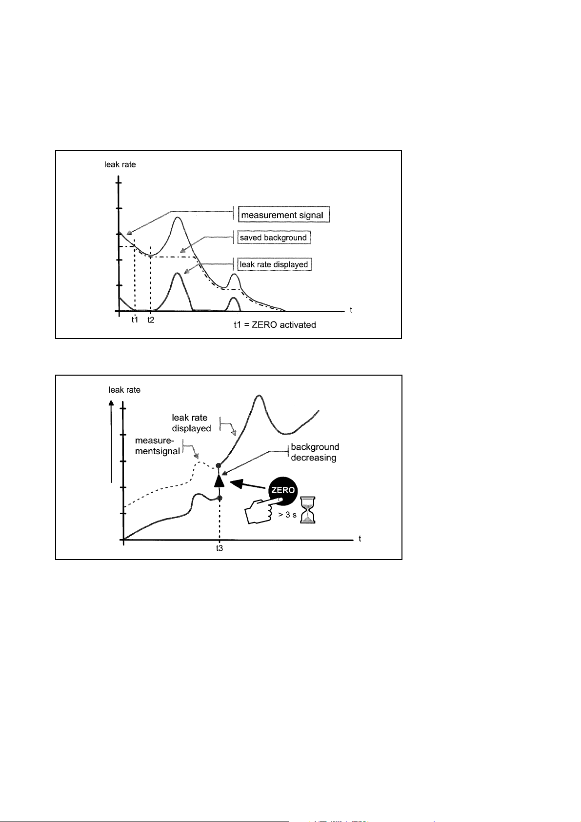
When pressing ZERO the currently measured leak rate is taken as a background
signal and is subtracted from all further measurements. As a result the displayed
leak rate then is
3.10.1 to select the time parameters of the venting.
1·10
1·10
After pressing ZERO (Fig. 13, t=1) the decreasing background is fitted to the
course (Fig. 13, t=2) automatically. When the measurement signal declines below
the saved background the underground value will automatically be equated with
the measurement signal. As soon as the measurement signal is increasing again
the saved decreasing value remains constant. Increasing of the signal are dis
played clearly as a leak So it is possible to recognize leaks even when the signal is
decreasing rapidly.
GA10218_002_C0 - 10/2016 - © Leybold GmbH
40
-8
mbarl/s
-12
mbarl/s
in GROSS
in FINE
-
Page 41
Operation
Fig. 13 Zero activation
Fig. 14 Undo zero
When you want to see the measurement signal (including underground) please
press the ZERO button again. The saved value will be reset to zero. The under
ground signal will not be suppressed anymore (Fig. 14).
-
MENU Button
When pressing the MENU button (Fig. 12/13) the selecting menu is shown at the
display. This function is not depending on the operating mode when calibrating.
If the menu is opened during the current session the operator will lead to the last
screen before the menu was left.
Pushing the MENU button again leads back to the screen of the previous working
mode. The software shows the last screen that was used before.
GA10218_002_C0 - 10/2016 - © Leybold GmbH 41
Menu button
Page 42

Operation
Softkeys
Special functions
Numerical entries
Soft Keys
The function of the eight Soft Keys Fig.12/1…8 depends on the current menu.
Special Functions
When inputs are allowed or when settings can be selected in a submenu two of the
Soft Keys always have the same function:
Soft Key no. 1 Fig. 12/1 is Cancle.
It allows to escape from the submenu without any changes of the present settings and return to the previous menu page.
Soft Key no. 8 Fig. 12/8 is OK.
The selected settings or edited values will be stored and the previous menu
page will be displayed again.
Numerical Entries
If you have opened a menu page where a digit can be changed please proceed in
the following way:
If you don’t want to change anything, press Soft Key no. 1 Cancle.
If you want to change the digit please proceed as follows:
1. The digit that can be changed is displayed inverted. With the arrows (Soft
Key no. 8) and (Soft Key no. 4) you can choose which digit you want to
change.
2. To change a digit to a specific number press the corresponding pair of numbers.
A submenu opens and the desired number can be selected. The submenu clo
ses automatically and the next digit of the total number now is inverted.
-
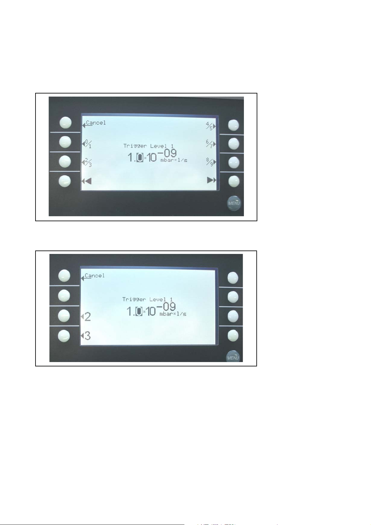
Example change trigger
3. Having reached the last digit all changes have to be confirmed by OK (softkey
no. 8). To correct a wrong entry press Cancel (softkey 1) or soft key 4
enter the desired value again.
Example
To change the trigger level 1.0 · 10-7 mbar l/s to 3 · 10-7 mbar l/s please press 2/3
(Soft Key no. 3,
not please change the digit with (softkey no. 8) or (softkey no. 4). With
the soft key no. 4 (Fig. 12) the chosen value can be selected.
Fig. 16) . Please consider that the first digit is displayed inverted. If
and
GA10218_002_C0 - 10/2016 - © Leybold GmbH
42
Page 43
Operation
Fig. 15 Numerical entry of the trigger level, sample of the digit
In the submenu press 3 (soft key no.4) Fig. 16
Fig. 16 Trigger level, change of the first digit
GA10218_002_C0 - 10/2016 - © Leybold GmbH 43
Page 44

Operation
3.5 Interfaces
Under Main menu > Settings > Interfaces the parameters for the interface can be
set.
Softkey 2: Location of control
The location of control for the leak detector can be defined
Softkey 3: Define recorder output
Customer defined selection for the recorder output
Softkey 4: RS232
Selection for the RS232
Softkey 5: Define PLC outputs (Control, digital out)
Customer defined selection for PLC outputs
Softkey 6: Define PLC inputs (Control 2, Digital in)
Customer defined selection for PLC inputs
Softkey 7: Scaling recorder outputs
Selection for the scaling of the recorder output
Softkey 8: PLC sample rate
Selection of the PLC sample rate
GA10218_002_C0 - 10/2016 - © Leybold GmbH
44
Page 45

Operation
0 0,45 0,52 0,97 2,6 5,97 8,2 8,65 V
-3 -2 -1 0
10
10
10
mbar,atm
1010
12
10 10
3
10-410-310 10 10 10 10
-2 -1 0 1 2
Pa
7,5E-47,5E
-3
7,5E
0,75 7,5 75 750
-2
Torr
Location of Control
Main menu > Settings > Interfaces > Location of control
Softkey 2: PLC
The PHOENIX L300i is controlled via the Digital In connector. The START,
STOP and ZERO buttons at the control panel and remote control are
locked.
Softkey 3: RS232
The PHOENIX L300i is controlled via RS232 interface by an external
computer. In this mode the PHOENIX L300i can not be controlled via
keyboard. The START, STOP and ZERO button at the machine are deac
tivated.
Softkey 4: All
The PHOENIX L300i is controlled via all possible controls, e.g. PLC,
RS232, Local.
Softkey 5: Local & PLC
The PHOENIX L300i is controlled via the Digital In connector or/and the
START, STOP and ZERO buttons at the control panel and remote
control.
Location of control
-
Softkey 6: Local & RS232
The PHOENIX L300i is controlled via the Digital In connector or/and the
START, STOP and ZERO buttons at the control panel and remote
control.
Softkey 7: Local
The PHOENIX L300i is controlled via the START, STOP and ZERO buttons at the control panel or remote control. This is the default setting.
Define recorder output
Main menu > Settings > Interfaces > Define recorder output
The signals to be recorded can be selected in this submenu. With the left keys the
pin can be selected, with the right keys a function is assigned to the selected pin.
The recorder output has 2 channels (
Fig. 18)
Define recorder output
Recorder output pirani
P1/P2
Fig. 17 Recorder output: Pirani PHOENIX L300i, P1 and P2. The complete characteristic Pirani line is shown in
the appendix.
GA10218_002_C0 - 10/2016 - © Leybold GmbH 45
Page 46

Operation
Selection recorder outputs
The following functions can be selected:
Off
The recorder output is switched off
P1 Pirani PHOENIX L300i
The inlet pressure P1 of the PHOENIX L300i will be shown logarithmic.
Fig. 17
P2 Pirani PHOENIX L300i
The fore vacuum pressure P2 of the PHOENIX L300i will be shown logarithmic. Fig. 17
P1 (L200)
The setting for the inlet pressure P1 is identical with those of the L200, i.e.
1000 mbar comply 4V with 0.5V/decade logarithmic scale. Users can
exchange their L200 for a PHOENIX L300i without changing pin
assignment.
P2 (L200)
The setting for the fore vacuum pressure P2 is identical with those of the
L200,i.e. 1000 mbar comply 4V with 0.5V/decade logarithmic scale.
Users can exchange their L200 for a PHOENIX L300i without changing
pin assignment.
Fig. 18
Fig. 18
Recorder output P1/P2
L200
LR mantissa
The leak rate mantissa is recorded linearly from 1...10V. Fig. 20
LR exponent
The exponent is recorded as step function: U = 1...10V with steps of 0,5V
-12
per decade, starting with 1V = 1·10
LR linear
There will be two decades, the lower decade with voltages from 0.1 to
1.0V, the upper from 1.0 to 10.0V output. The scale is linear. The "Zoom
recorder output (leak rate) upper limit ( = 10V)" specified exponent deter
mines the upper decade.
LR log
The fundamental output voltage is scaled logarithmic and can be freely
chosen. The voltage output ranges from 1 to 10 V with adjustable steps
of 0,5/1/2/2,5/5 to 10 V per decade (
mbarl/s. Fig. 19
Fig. 21 shows the default setting)
-
GA10218_002_C0 - 10/2016 - © Leybold GmbH
46
Page 47
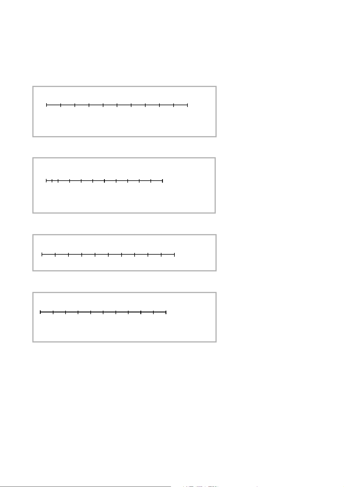
Fig. 18 Recorder output: P1 and P2 L200
012345678910
V
-3
-1 +1
+3
10
10 10
10
10
+5
mbar,Pa,Torr
10
10 10 10
-6
-4
-2 -0
atm
0
1
2345678910V
-12
-10 -8 -6
10
10 10 10 mbarl/s, Pam•/s
Torrl/s, sft•/yr
oz/yr, g/a
-4 -2 0 +2
10 10 10
10
+4
10
0,5
10
-13
012345678910
V
1234567
89
Mantissa
012345678910V
-14
-13 -12 -11
10
10 10 10 mbarl/s, Pam•/s
Torrl/s, sft•/yr
oz/yr, g/a
-10 -9 -8 -7
10 10 10
10
-6
10 10
-5
Operation
Recorder output leak rate
exponent
Recorder output leak rate
mantissa
Fig. 19 Recorder output: Leak rate exponent
Fig. 20 Recorder output: Leak rate mantissa
Fig. 21 Recorder output: Leak rate logarithmic, default setting
Recorder output leak rate
logarithmic
GA10218_002_C0 - 10/2016 - © Leybold GmbH 47
Page 48

Operation
RS232
Define PLC outputs
Caution
RS232
Main Menu > Settings > Interfaces > RS232
Softkey 2: Baudrate and end sign
Settings for the baudrate selectable between 1200 and 19200, as well as
endsign between CR+LF, CR or LF.
Softkey 3: Data, Parity, Stop bits
The settings for Data (7 or 8), Parity (Even, Odd, None) and Stop bits (1 or
2) can be selected
Softkey 7: RS 232 Protocol
The protocol from the RS 232 can be chosen between: L200 size,
Diagnostic, L200 Leak Ware and ASCII code.
The calibration function of Leak Ware is not suitable with the use of a Phoenix.
Define PLC outputs
Main Menu > Settings > Interfaces > Define PLC outputs
The following relay outputs are available for further signal processing. The
maximum rating for the relay contacts is 60V
The contacts are numbered from bottom to top.
All pins of digital I/O, digital out and recorder must not be connected with
voltages higher than 60V DC/25V AC (to grounding equipment conductor) or
reach this threshold.
AC/1A.
Pin
1 PLC in free selectable
2 PLC in free selectable
3 PLC in free selectable
4
5 to 7 Digital out free selectable, 5 center contact, 6 normally open
8 to 10 Digital out free selectable
11 to 13 Digital out free selectable
14 to 16 Digital out free selectable
Description of the operation mode of the Digital Out. The pin assignment for
contacts 8 to 16 follows the same order as for pins 5 to 7.
The actual pin setting can be seen under Info / View internal data / page 7.
The following digital out signals are selectable.
Trigger 1; Trigger 2 and 3 analog Trigger 1
Is open in case Trigger Level 1 is exceeded or the machine is not in condition of
Assignment
GND
contact, 7 normally closed contact
GA10218_002_C0 - 10/2016 - © Leybold GmbH
48
Page 49

measuring.
Zero active:
Is closed in case Zero function is running.
Ready:
Is closed in case machine is in measurement mode (Emission on, no error).
CAL active
Closed when machine is in calibrating routine.
CAL Request
Is opened in case of calibration request. During external calibration a open output
indicates that the external calibrated leak has to be closed.
Fail
Open when a error is shown.
Warning
Open when a warning is shown.
Operation
Gas ballast
Closed when gas ballast is active.
Open
Open all time.
Close
Closed all time.
Recorder Strobe
Closed in case recorder output is invalid. Only used when record output is set on
„leak rate“.
Pump down
Open when machine is evacuating the test object.
Standby
Open when machine is in Standby or Vent mode.
Vented
Open when machine is in Vent mode.
Emission on
Open when emission is on.
Define PLC inputs
Main menu > Settings > Interfaces > Define PLC inputs
These inputs can be used to control the PHOENIX L300i with a programmable
logic control (PLC).
Define PLC inputs
Maximum input voltage 35V.
Pin
1 PLC in free selectable
2 PLC in free selectable
Assignment
Caution
GA10218_002_C0 - 10/2016 - © Leybold GmbH 49
Page 50

Operation
Pin
3 PLC in free selectable
4 PLC GND
Description of operation mode of the Digital In.
The contacts are numbered from bottom to top.
The PLC inputs are working only if the correct location of control has been set.
The actual pin setting can be seen under Info / View internal data / page8.
Zero:
Change from low to high: activate zero
Change from high to low: deactivate zero
Start:
Change from low to high: activate START
Stop:
Change from low to high: activate STOP
When this inlet is longer high than chosen then ventilate it additionally.
Purge/gas ballast:
Change from low to high: activate purge/gas ballast
Change from high to low: deactivate purge/gas ballast
Assignment
Clear:
Change from low to high: confirm error message
CAL:
Change from low to high:
When machine is in standby mode: start internal calibration. In case machine is
measurement mode: start external calibration. (Premise: external calibration test
leak has to be open and leak rate signal is stable)
Change from high to low:
External calibration: approve that external test leak is closed and leak rate signal is
stable.
High means: U > 13V(approximately 7mA)
Low means: U < 7V
The level of the logic signals must not exceed 35V.
CAL intern:
Change from low to high: The Machine starts an internal calibration independent
from the mode the machine is running in.
CAL extern:
Change from low to high: The Machine starts an external calibration independent
from the mode the machine is running in.
Change from high to low: approve that external test leak is closed and leak rate
signal is stable.
Signals at these inputs are only accepted if the location of control is set to „PLC“,
“All“ or „Local and PLC“.
GA10218_002_C0 - 10/2016 - © Leybold GmbH
50
Page 51

Operation
Scaling Recorder Output
Main menu > Settings > Interfaces > Scaling recorder output
Here the scaling of the recorder output can be adjusted. This adjustment is possible only when the signal LR lin or LR log is chosen.
Softkey 2:
The decade of the upper leak rate can be decreased
Softkey 3:
Decrease scaling of the previously adjusted value in steps of 0.5, 1, 2,
2.5, 5, 10 Volt/decade. The complete array covers 10 V.
Softkey 5: ?
Help text.
Softkey 6:
The decade of the upper leak rate can be increased
Softkey 7:
Increase scaling of the previously adjusted value in steps of 0.5, 1, 2, 2.5,
5, 10 Volt/decade. The complete array covers 10 V.
Scaling recorder output
Example:
Upper limit value is adjusted to 10-5 (= 10V)
Scaled to 5 V /decade
Lower limit value consequently is 10-7 (= 0 V)
PLC Sample Rate
Main menu > Settings > Interfaces > PLC Sample rate
Softkey 2:
Decreasing the PLC sample rate down to the minimum of 10 ms. This
might be necessary if exchanging an L200 to the PHOENIX L300i to stay
compatible.
Softkey 3:
Increasing the PLC sample rate to the maximum of 100 ms.
3.6 Operation
By pressing the MENU push button Fig. 12/13 the main menu will be displayed
regardless of the current working mode or status of the PHOENIX L300i.
The main menu Fig. 23 leads the operator to several submenus described in the
following chapters. The main menu is identically for all PHOENIX L300i models.
The next page gives an overview of the entire menu architecture Fig. 23.
The overview of the menu architecture corresponds to the PHOENIX L300i,
differing menu points or setting possibilities for the PHOENIX L300i DRY and PHO
ENIX L300i MODUL are described in the respective menu point.
GA10218_002_C0 - 10/2016 - © Leybold GmbH 51
-
Page 52
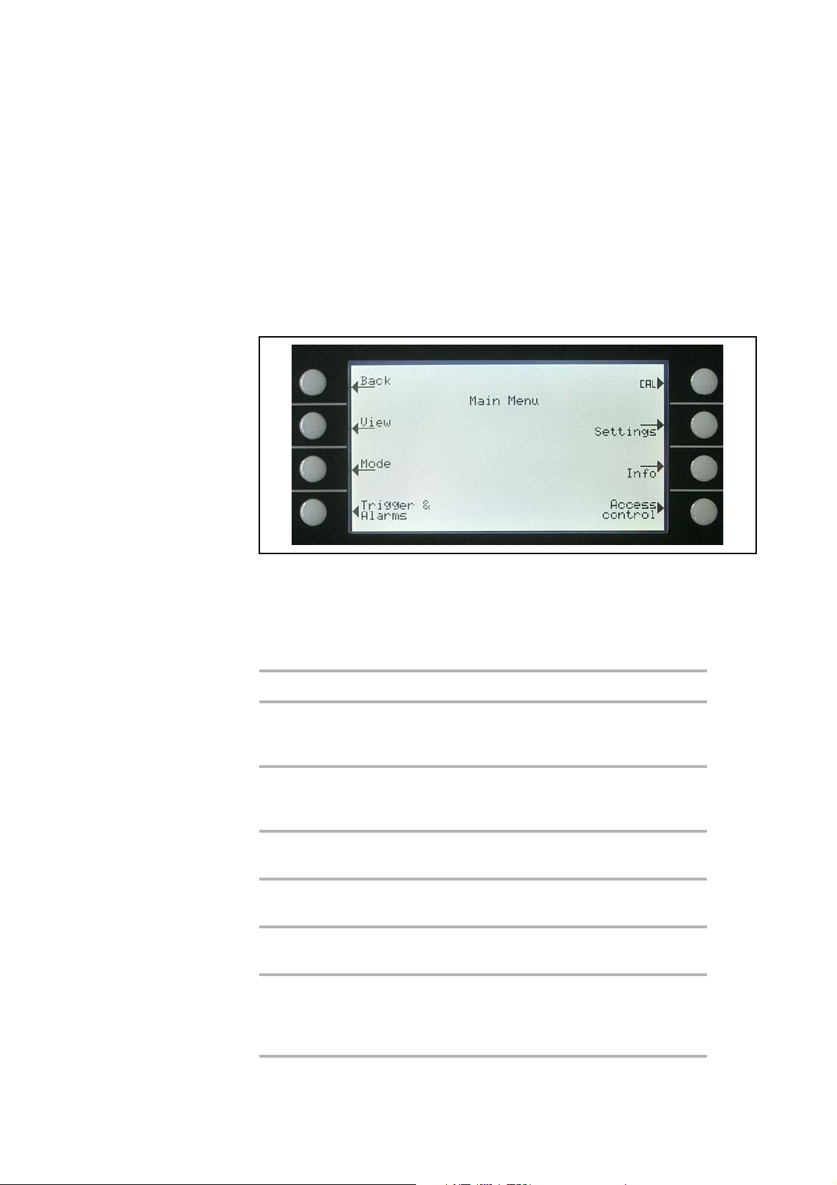
Operation
3.6.1 Main Menu
The main menu Fig.23 shows 7 sub-menus. In these sub-menus groups of
technical features are put together logically. From here the next levels of the menu
tree can be reached.
All following chapters show the path to get to the described menu line right
underneath the headline.
Fig. 22 Display: Main menu
Explanation to Fig.22:
Key No. Name Description
1 Back Return to the previous screen.
2 View Display settings like scaling, contrast, sys-
tem background.
Please refer to Chapter 3.6.2.
3 Mode Selection of the working modes Vacuum or
Sniff
Please refer to Chapter 3.7.
4 Trig ge r & Al ar ms Settings of units, trigger levels and alarms.
Please refer to Chapter 3.7.
5 Calibration Calibration of the PHOENIX L300i.
Please refer to Chapter 3.13.
6 Settings Settings of internal machine parameters.
Please refer to Chapter 3.10.
7 Information Information on the PHOENIX L300i
8 Access Control Access restrictions.
GA10218_002_C0 - 10/2016 - © Leybold GmbH
52
(electrical and vacuum data) and service
menu.
Please refer to Chapter 3.11.
Please refer to Chapter 3.12.
Page 53
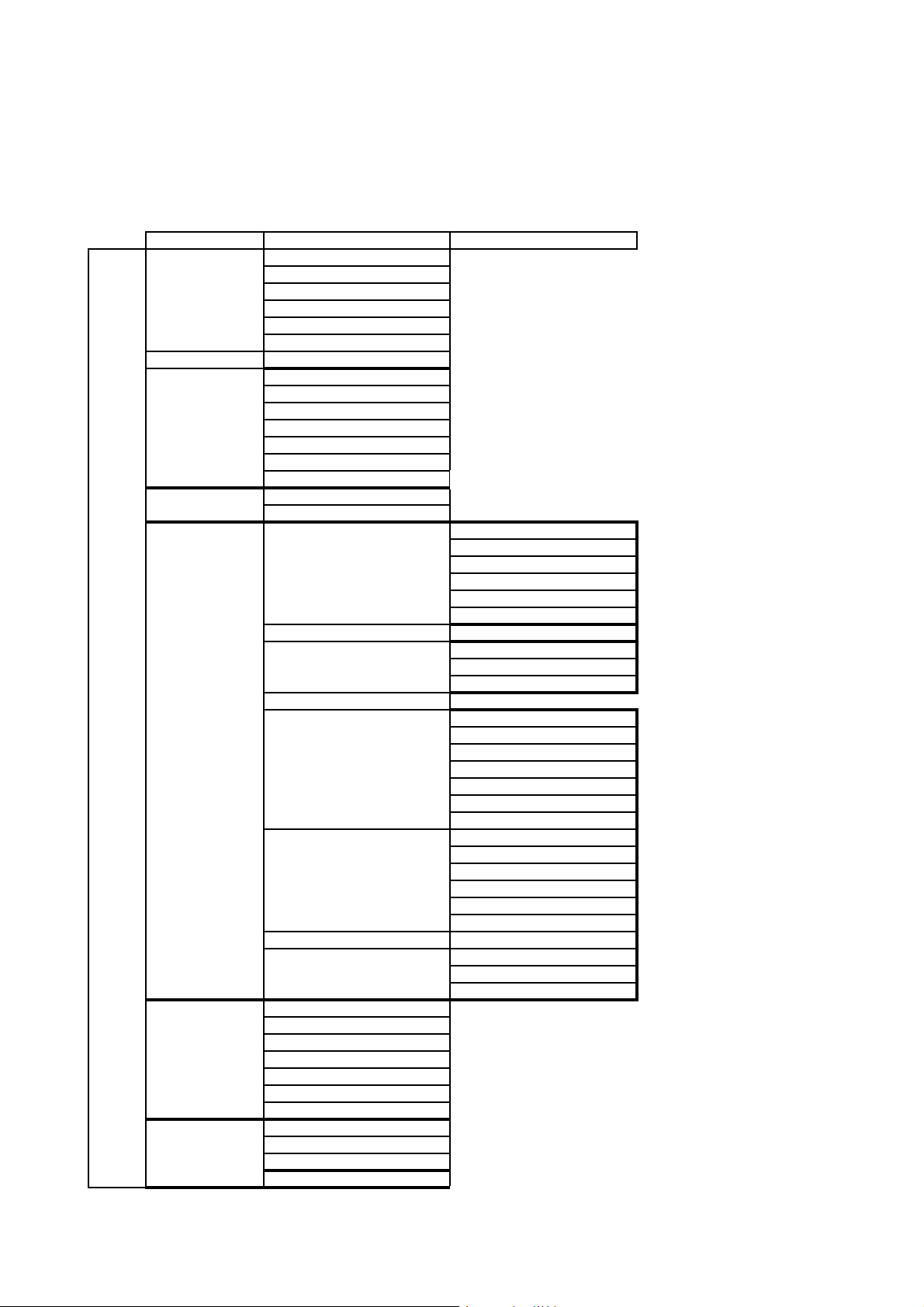
Operation
1. Level 2. Level 3. Level
View Scale linear / logarithmic
Display range
Time axis
Contrast
Background in standby
Lower display limit
Mode Sniff/Vacuum
Trigger & Alarms Trigger Level 1
Trigger Level 2
Trigger Level 3
Units
Volume
Alarm delay
Audio alarm type
Calibration internal
external
Settings Vacuum settings Vent delay
Vac uu m ra nge s
Partial flow setup/pump setup
Sniffer factor
Machine factor
Leak rate internal test leak
Purge in measurement
Filter & Background Background suppression
Calculate inlet area background
Leak rate filter
Mass
Interfaces Location of control
Main Menui
Miscellaneous Time & Date
Parameter save / load Load parameter set
Monitoring functions Pressure limits for sniff mode
Information View settings
View internal data
Vacuum dia gr am
View error list
Calibration history
Calibration factors
Service
Access Control Access to CAL function
Change Device-PIN
Change Menu-Pin
Zero
Define recorder output
RS232
Define PLC outputs
Define PLC inputs
Scaling recorder output
PLC sample rate
Language
Calibration request
Service internal forepump
Service internal exhaust oil filter
Service message exhaust oil filter
Maximum evacuation time
Pressure limits for vacuum mode
Fig. 23 Overview menu structure
GA10218_002_C0 - 10/2016 - © Leybold GmbH 53
Page 54
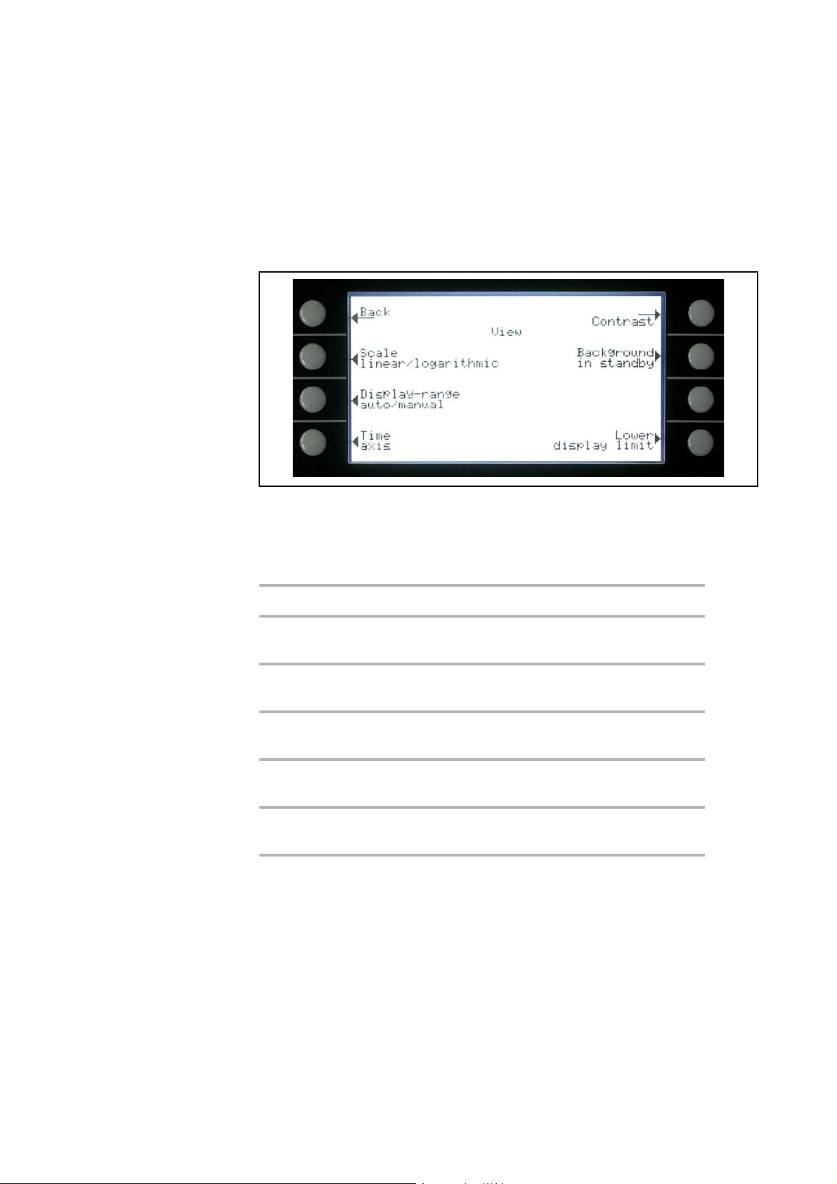
Operation
3.6.2 View
Main menu > View
In this menu Fig.24 all features that influence the data display are put together.
Fig. 24 Display: View Menu
Explanation to Fig.24:
Key No. Name Description
1 Back Return to the main menu.
2 Scale linear/logarithmic Settings for bargraph and trend mode.
Please refer to Chapter 3.6.3
3 Display range auto/
manual
4 Time axis Time axis in trend. Please refer to
5 Contrast Display contrast. Please refer to Chap-
6 Background in standby Background displayed or not. Please
8 Lower display limit Setting of the display limit. Please refer
Manual or automatic scaling. Please
refer to Chapter
Chapter
ter 3.6.6
refer to Chapter
to Chapter
3.6.5
3.6.4
3.6.7
3.6.8
3.6.3 Scale Linear/Logarithmic
Main menu > View > Scale linear/logarithmic
These settings apply to the bargraph (= bar underneath the digital figures in the
measurement mode) and Y-axis in the trend diagram.
The scale of the bargraph can either be linear or logarithmic. With the arrows
( and ) it can be determined how many decades the bargraph and Y-axis are
covered. Usually a logarithmic scale is recommended because leak rates may
change easily over several decades. Default setting is logarithmic with 4 decades.
GA10218_002_C0 - 10/2016 - © Leybold GmbH
54
Page 55

Softkey 2: Linear
Pressing this key switches the display to a linear scale, starting at zero.
Softkey 3: (Number of decades)
Pressing this key reduces the number of displayed decades. The
minimum value is 2 decades. Only available if log (softkey 6) was chosen.
Softkey 6: Logarithmic
The scaling will be displayed logarithmically.
Softkey 7: (Number of decades)
Increase the number of displayed decades. Maximum value is 9
decades. Only available if log (softkey 6) was chosen.
Operation
3.6.4 Display-Range Auto/Manual
Main menu > View > Display range auto/manual
The upper limit of the displayed leak rate range can be set manually or
automatically. These settings apply to the bargraph (= bar underneath the digital
figures in the measurement mode and y-axis in the trend mode).
With the upper limit defined here the lower limit is set to a value based on the
number of decades.
Softkey 2: Manual
The upper limit of the displayed range can be set manually.
Softkey 3:
Decrease the upper limit if manual is chosen. The minimum value is
-11
10
mbar l/s
Softkey 5: ?
Help text
Softkey 6: Automatic
The limit of the displayed range will be chosen automatically.
Softkey 7:
Increase the upper limit if manual is chosen. The maximum value is
+3
mbar l/s
10
Softkey 8:
Save the settings and return to the previous menu.
If linear scale is selected, the lower limit is always zero. The upper limit is only a
default value. You can change this on the measurement screen with the Soft Key 6
and 7 if you have chosen manual display ranging.
GA10218_002_C0 - 10/2016 - © Leybold GmbH 55
Page 56

Operation
3.6.5 Time Axis
Main menu > View > Time axis
The length of the time axis in trend mode can be changed in given steps between
16
… 960 seconds.
Softkey 3:
Decrease the length of the time axis. The minimum value is 16 seconds.
Softkey 5: ?
Help text
Softkey 7:
Increase the length of the time axis. The maximum adjustable value is 960
seconds.
3.6.6 Contrast
Main menu > View > Contrast
The contrast of the display can be changed. The recommended value under regular conditions is about 50 (Default setting).
Softkey 3:
Fade the contrast to dark. The minimum values is 0.
Softkey 4: Invert display
Invert the contrast of the screen, that means background dark and font
bright.
Softkey 5: ?
Help text
Softkey 7:
Fade the contrast to light. The maximum value is 99.
If by accident the display has been set too bright or too dark so that it can not be
read off, this may be changed as follows:
Switch off the PHOENIX L300i and turn it on again. During the run-up phase press
the key no. 3 or 7 so long until the display can be read properly again. This setting
is saved to the EPROM only after confirming this through the contrast menu. If this
setting is not confirmed, the former setting will be applied after switching on the
instrument on again.
GA10218_002_C0 - 10/2016 - © Leybold GmbH
56
Page 57

3.6.7 Background in standby
Main menu > View > Background in standby
The internal background leak rate can be displayed in standby mode or not.The
default setting is OFF.
Softkey 3: Off
The background leak rate will not be shown.
Softkey 5: ?
Help text.
Softkey 7: ON
The background leak rate will be shown.
Operation
The internal background is generated by residual gas (e. g. helium) that has not
been pumped away yet. Sources for residual gas are air or absorbed gases from
the inner surfaces of the PHOENIX L300i. This internal background will never dis
appear totally. Very clean systems which have been pumped for a long time will
-11
show a background in the 10
background level is in the 10
When pressing START the current internal background is subtracted from all
further measured signals automatically. Thus it is made sure that only the net leak
rate from the part under test is measured.
When switched to standby / Vent again a new internal background is calculated
after 25
when the value is underlined, the actual background signal will be subtracted. If
you press START when the value is not underlined, the old background signal from
the last standby will be subtracted.
s. The updated value is underlined. This means that if you press START
mbar l/s range. Under normal conditions the
-10
mbar l/s or low 10-9 mbar l/s range.
-
3.6.8 Lower Display Limit
Main menu > View > Lower display limit
This mode limits the lower detection limit of the measured leak rate. This is valid for
vacuum mode only.
Softkey 3, 7:
Changing of the lower detection limit between 1 · 10-9 and 1 · 10
mbarl/s.
-12
The lower limit for the PHOENIX L300i DRY ranges between 1 · 10-9 and
-11
1 · 10
Softkey 5: ?
Help text
mbarl/s.
GA10218_002_C0 - 10/2016 - © Leybold GmbH 57
Page 58
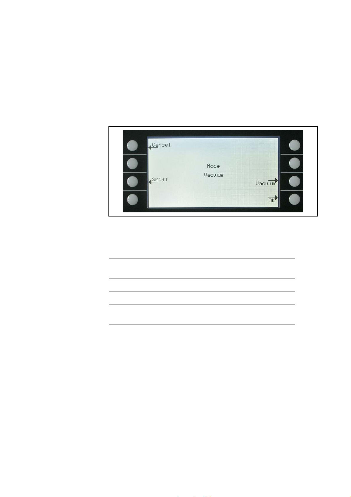
Operation
3.7 Mode
Main menu > Mode
The mode menu Fig.25 enables the submenu to select the different working
modes.
Fig. 25 Display: Mode menu
Explanation to Fig.25:
Key No. Name Description
1 Cancel Return to the main menu without any
changes of the present settings.
3 Sniff The sniffer mode will be used.
7 Vacuum The vacuum mode will be used.
8 OK Save the settings and return to the previous
menu.
GA10218_002_C0 - 10/2016 - © Leybold GmbH
58
Page 59
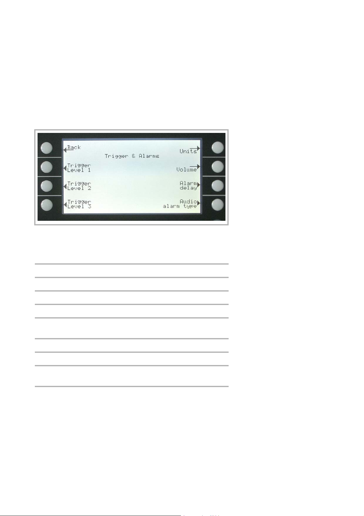
3.8 Trigger & Alarms
Main menu > Trigger & Alarms
The trigger levels, the volume of the loudspeaker and the units of leak rates and
pressures can be set in this menu Fig.26.
Operation
Fig. 26 Display: Trigger & Alarms Menu
Explanation for Fig.26:
Key No. Name Description
1 Back Return to the main menu.
2 Trigger level 1 Definition of Trigger level 1. Chapter 3.8.1
3 Trigger level 2 Definition of Trigger level 2. Chapter 3.8.2
4 Trigger level 3 Definition of Trigger level 2. Chapter 3.8.3
5 Units Selection of leak rate and pressure units.
Refer to Chapter
6 Vol ume Refer to Chapter 3.8.5
7 Alarm delay Refer to Chapter 3.8.6
8 Audio alarm type Choice of different alarm types. Refer to
Chapter
3.8.7
3.8.4
3.8.1 Trigger Level 1
Main menu > Trigger & Alarms > Trigger level 1
The value of the first trigger level can be set. See Numerical entries for the description of the entry.
Trigger 1, 2 and Trigger 3 are programmable switching thresholds. When these
thresholds will be exceeded the PHOENIX L300i reacts as follows:
Display
In the status line of the display the signs for Trigger 1, 2 and Trigger 3 are displayed
inverted if the leak rate exceeds (becomes higher than) the programmed value.
(see
Fig. 10)
GA10218_002_C0 - 10/2016 - © Leybold GmbH 59
Page 60

Operation
Relay Output
The trigger-relais of the digital out switches. Please refer to Chapter 3.5 Digital out,
for further details.
Alarm/Loudspeaker
Additionally Trigger level 1 defines at which level the various alarm types react (See
Chapter
3.8.7)
3.8.2 Trigger Level 2
Main menu > Trigger & Alarms > Trigger level 2
The value of the second trigger level can be set. Please refer to Numerical entries
for the description of the entry.
If Trigger 2 is exceeded the corresponding relay will switch. This is also indicated at
the display (see Chapter
3.8.1).
3.8.3 Trigger Level 3
Main menu > Trigger & Alarms > Trigger level 3
The value of the third trigger level can be set. Please refer to Numerical entries for
the description of the entry.
If Trigger 3 is exceeded the corresponding relay will switch. This is also indicated at
the display (see Chapter.
3.8.1).
3.8.4 Units
Main menu > Trigger & Alarms > Units
The preferred leak rate unit can be selected. There is the choice of 4 (mbar, Pa,
Torr, atm) pressure units and 5 leak rate units (mbar
ft3/yr).
s, s
In Sniff mode the following measuring units are selectable: ppm, g/a eq (helium
leak rate is equivalent with leak rate R134a), oz/yr eq (helium leak rate is equivalent
with leak rate R134a).
Softkey 2:
Scroll up to select a pressure unit.
Softkey 3:
Scroll down to select a pressure unit.
l/s, Pa m3/s, Torr l/s, atm cc/
Softkey 6:
Scroll up to select a leak rate unit.
Softkey 7:
Scroll down to select a leak rate unit.
GA10218_002_C0 - 10/2016 - © Leybold GmbH
60
Page 61

3.8.5 Volume
Main menu > Trigger & Alarms > Volume
The minimum loudness and the actual volume of the loudspeaker can be adjusted.
The minimum loudness is the minimum speaker volume that cannot be exceeded
to even lower values. Thus it is avoided that the actual volume is accidentally adju
sted to a value that is below the noise level of the environment.
The actual volume can be adjusted between 15 (maximum) and the value defined
as minimum loudness.
Softkey 2:
Decrease the minimum loudness. The minimum value is 0.
Softkey 3:
Decrease the actual volume. The minimum value is limited by the
minimum volume.
Operation
-
Softkey 4: Beep off / Beep on
Softkey 5: ?
Help text.
Softkey 6:
Increase the minimum volume. The maximum value is 15.
Softkey 7:
Increase the regular volume. The maximum value is 15.
3.8.6 Alarm Delay
Main menu > Trigger & Alarms > Alarm delay
In some applications (for instance during pump down in a „chamber test system“) it
might be necessary to block an alarm for some time after pressing START.
This delay time of the alarm can be changed.
Softkey 3:
Decrease the delay time. The minimum value is 0 seconds.
Softkey 5: ?
Help text.
Softkey 7:
Increase the delay time. The maximum value is 10 minutes up to infinity.
After pressing START the loudspeaker is activated as soon as the leak rate drops
below trigger level 1 or after the entered alarm delay time has elapsed. This setting
is only active for the audio alarm types SETPOINT and TRIGGER ALARM (See
chapter
3.8.7).
GA10218_002_C0 - 10/2016 - © Leybold GmbH 61
Page 62
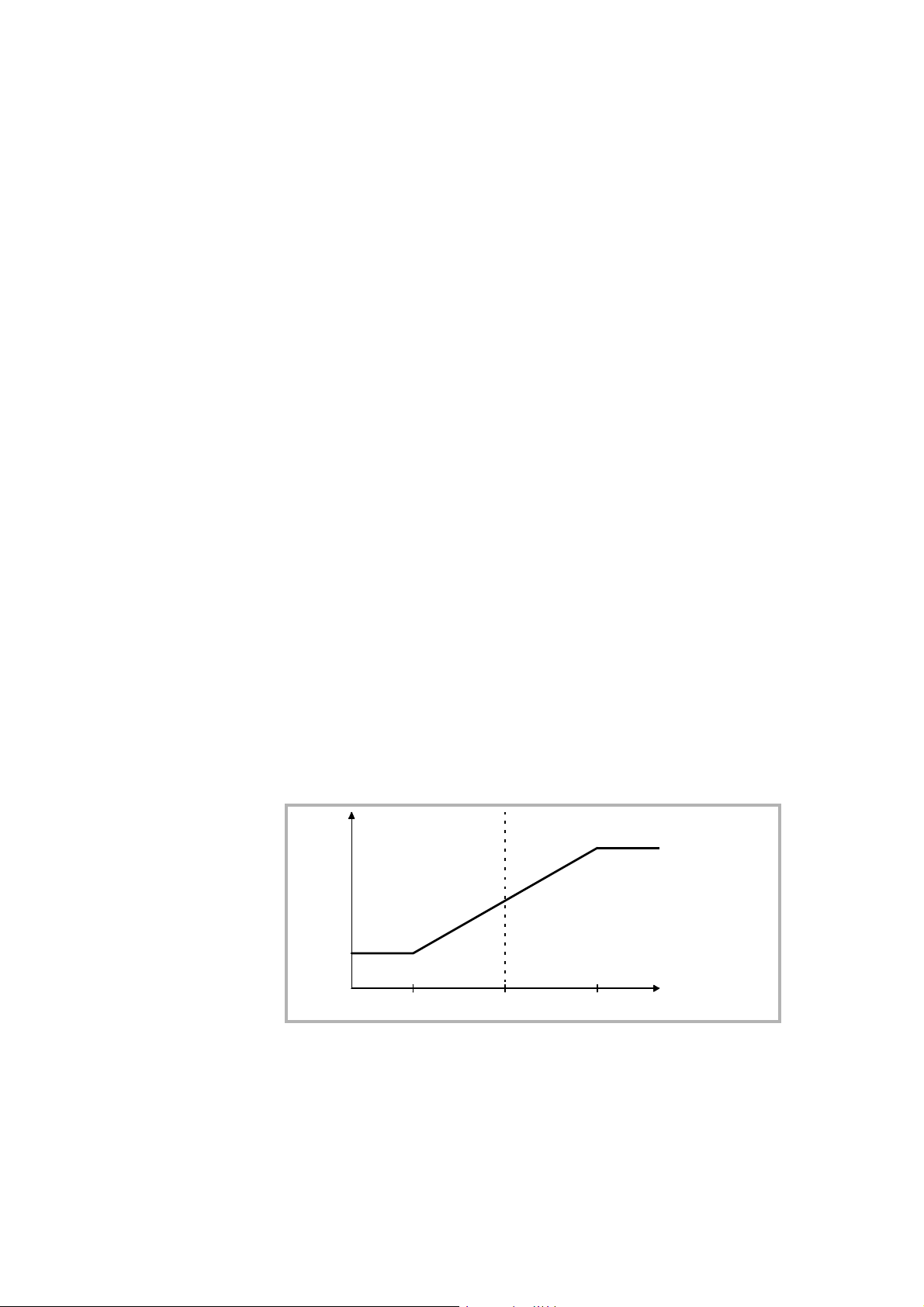
Operation
f
LRTr. 10.1 • Tr. 1 10 • TR. 1
2570 Hz -
491 Hz -
3.8.7 Audio Alarm Type
Main menu > Trigger & Alarms > Audio alarm type
The audio alarm type can be chosen.
Softkey 2: Pinpoint
This function is for localization of a known leak rate value.
Softkey 3: Leak rate prop.
The sound will be proportional to the leak rate signal.
Softkey 5: ?
Help text
Softkey 6: Setpoint
The sound will be proportional to the leak rate signal only if trigger 1 is
exceeded.
Softkey 7: Trigger alarm
An alarm sounds when the trigger 1 is exceeded.
Pinpoint
Leak rate prop.
Pinpoint
The tone of the acoustical signal changes its frequency only in a leak rate-window
Fig. 27 which ranges from one decade below the Trigger level 1 up to one decade
above the Trigger level 1. Below the window the tone is constantly low, above the
window it is constantly high.
Example: The Trigger level 1 is 4·10-7 mbar l/s. So the window where the tone
-8
changes reaches from 4·10
Fig. 27 Pinpoint: Change of the frequency in the leak rate window (TR1=Triggerlevel 1)
Leak rate prop.
The frequency of the acoustic output is proportional to the reading on the bargraph
display. The frequency ranges from 300 Hz to 3300 Hz. Please refer to Chapter
3.6.3 for the definition of the number of decades.
mbar l/s up to 4·10-6 mbar l/s.
62
GA10218_002_C0 - 10/2016 - © Leybold GmbH
Page 63
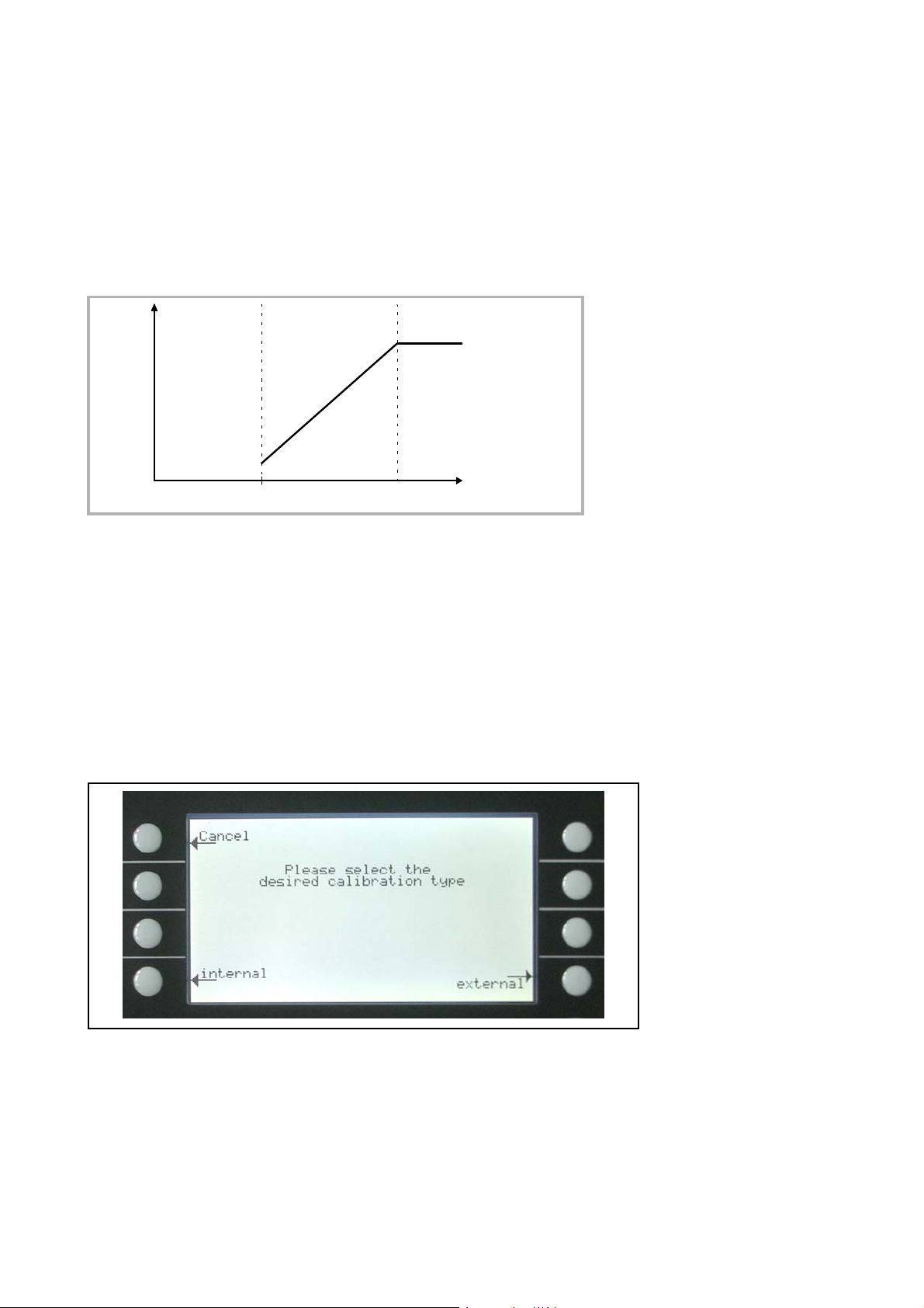
Operation
f
LRTr. 1
no tone
375 Hz -
1000 • TR.1
3000 Hz -
Setpoint
The tone is off as long as the leak rate is below the Trigger level 1. Above Trigger 1
the tone varies proportional to the leak rate
Fig. 28 Setpoint: Change of the frequency above the trigger level 1 (TR1= Trigger level 1)
Trigger alarm
As soon as the leak rate increases above trigger level 1, a multi-tone signal is
generated. The tone does not vary with the leak rate.
Fig. 28.
3.9 Calibration
Main menu > Calibration
Setpoint
Trigger Alarm
In the menu Calibration Fig. 29 the selection between internal and external calibra-
tion can be chosen.
Please refer to Chapter 3.13 Calibration for a detailed description of the calibration.
Fig. 29 Display: Calibration menu
GA10218_002_C0 - 10/2016 - © Leybold GmbH 63
Page 64
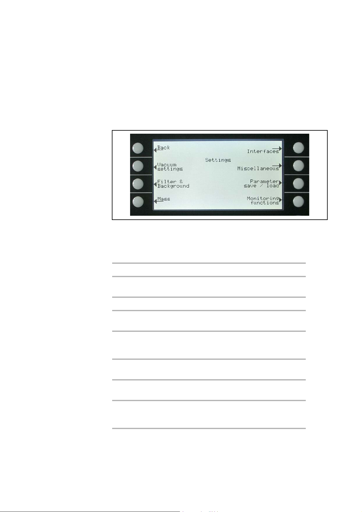
Operation
3.10 Settings
Main menu > Settings
This menu Fig. 30 allows to observe and to change the adjustment of the internal
machine settings.
Fig. 30 Display: Settings menu
Explanation for Fig.30:
Key No. Name Description
1 Back Return to the main menu.
2 Vacuum settings Settings of vacuum system related func-
tions. See chapter 3.10.1
3 Filter & Background See Chapter 3.10.2
4 Mass Switching between Helium and Hydro-
gen. See Chapter 3.10.3
5 Interfaces Settings for electrical communication and
selection for control location See Chapter
3.5 for detailed information.
6 Miscellaneous Settings like date or time. See Chapter
3.10.4
7 Parameter save / load Store and load sets of parameters. See
Chapter
3.10.5
8 Monitoring functions Choose functions of protection of the
GA10218_002_C0 - 10/2016 - © Leybold GmbH
64
PHOENIX L300i in this mode. See Chap
ter 3.10.6
-
Page 65

Operation
3.10.1 Vacuum Settings
Main menu > Settings > Vacuum settings
This menu allows to observe and to change the settings belonging to the vacuum
system.
Softkey 3: Vent delay
Definition of delay time until the PHOENIX L300i is vented
Softkey 4: Vacuum ranges
Selection of the vacuum working modes
Softkey 5: Partial flow setup/Forepump setup
Selection of partial flow mode and forepump type
Softkey 6: Sniffer factor
Setting for the sniffer factor
Softkey 7: Machine factor
Setting for the machine factor
Softkey 8: Leak rate internal test leak
Setting for the internal test leak
Vacuum settings PHOENIX
L300i
The menu for the PHOENIX L300i DRY version allows the following vacuum settings which varies to the PHOENIX L300i:
Softkey 3: Vent delay
Definition of delay time until the PHOENIX L300i is vented
Softkey 4: Vacuum ranges
Selection of the vacuum working modes
Softkey 5: Purge in measurement
The purging during measurement mode can be switched on
Softkey 6: Sniffer factor
Setting for the sniffer factor
Softkey 7: Machine factor
Setting for the machine factor
Softkey 8: Leak rate internal test leak
Setting for the internal test leak
Vacuum settings PHOENIX
L300i DRY
GA10218_002_C0 - 10/2016 - © Leybold GmbH 65
Page 66

Operation
Vacuum settings PHOENIX
L300i DRY MODUL
The menu for the PHOENIX L300i MODUL version allows the following vacuum
settings which varies to the PHOENIX L300i:
Softkey 2: Automatic purge
Definition of automatic purge function in standby
Softkey 3: Vent delay
Definition of delay time until the PHOENIX L300i is vented
Softkey 4: Vacuum ranges
Selection of the vacuum working modes
Softkey 5: Partial flow setup/Forepump setup
Selection of partial flow mode and forepump type
Softkey 6: Sniffer factor
Setting for the sniffer factor
Softkey 7: Machine factor
Setting for the machine factor
Softkey 8: Leak rate internal test leak
Setting for the internal test leak
Automatic purge
Vent delay
Automatic purge
Main menu > Settings > Vacuum settings > Automatic purge
Through this menu is it possible to start automatic purge for 20 seconds
automatically.
This setting is only possible for the PHOENIX L300i MODUL (refer to vacuum settings PHOENIX L300i MODUL)
Softkey 3:
The function automatic purge is off.
Softkey 6:
The function automatic purge is on. When changing from measure to
standby the forevacuum pump will be purged automatically for 20
seconds.
Vent delay
Main menu > Settings > Vacuum settings > Vent delay
Through this menu item it is possible to define the delay time until the inlet port is
vented when operating the STOP button. When the STOP button is pressed for a
period of time which is shorter than the delay time specified here, the PHOENIX
L300i will just change to standby mode.
When the STOP button is pressed for a period of time which is longer than the
delay time specified here, the PHOENIX L300i will vent the inlet port.
Off
ON
GA10218_002_C0 - 10/2016 - © Leybold GmbH
66
Page 67

Softkey 2: Immediately
The inlet port will be vented immediately after pressing the STOP button.
Softkey 3: After 1 second
The inlet port will be vented with a time delay of 1 second.
Softkey 4: After 1.5 seconds
The inlet port will be vented with a time delay of 1.5 second.
Softkey 5: ?
Help
Softkey 6: after 2 seconds
The inlet port will be vented with a time delay of 2 second.
Operation
Softkey 7: No venting
The inlet port cannot be vented with the STOP button.
Vacuum ranges
Main menu > Settings > Vacuum settings > Vacuum ranges
With this menu you can adjust different modes concerning the activity of leak
detection. This setting is only active in vacuum mode (see Chapter 3.5).
Softkey No. 2: GROSS only
In this mode the PHOENIX L300i remains at the inlet flange after falling
below 15
ENIX L300i switches automatically into evacuation mode. The smallest
detectable leak rate is 1 ·10
Softkey No. 3: FINE only
In this mode the PHOENIX L300i remains after falling below 0,2 mbar at
the inlet flange. Valve V1 will be closed. When the pressure at the inlet
flange is increasing >
into evacuation mode. The advantage of FINE only is that while this mode
is running no valve will switch and the PHOENIX L300i has a high
pumping speed.
mbar. When the pressure is increasing over 15 mbar the PHO-
-8
mbarl/s.
0.2 mbar the PHOENIX L300i switches immediately
Vacuum ranges PHOENIX
L300i DRY/PHOENIX L300i
MODUL
Softkey No. 4: GROSS only 920 Hz
In this mode the turbo pump of the PHOENIX L300i works at reduced
-9
speed. Therefore the smallest detectable leak rate is 3 ·10
function can be used to replace the L200 in Gross only mode equivalent
Taste No. 5: ?
Help text
Softkey No.6 Partial flow enable
mbarl/s. This
GA10218_002_C0 - 10/2016 - © Leybold GmbH 67
Page 68

Operation
If the PHOENIX L300i or the PHOENIX L300i MODUL is used with a partial flow system this vacuum mode must be enabled before. The setup for
the partial flow mode is described in partial flow setup
Softkey No. 7: Normal (default settings)
This is the default setting. The activity runs as explained in Chapter 1.1.1.
Vacuum ranges PHOENIX
L300i DRY
The PHOENIX L300i DRY allows the vacuum ranges as follows:
Softkey No. 2: GROSS only
In this mode the PHOENIX L300i DRY remains at the inlet flange after falling below 15 mbar. When the pressure is increasing over 15 mbar the
PHOENIX L300i DRY switches automatically into evacuation mode. The
smallest detactable leak rate is 1 ·10
Softkey No. 3: FINE only
In this mode the PHOENIX L300i DRY remains after falling below
0,1
mbar at the inlet flange. Valve V1 will be closed. When the pressure at
the inlet flange is increasing >
ches immediately into evacuation mode. The advantage of FINE only is
that while this mode is running no valve will switch and the leak detector
has a high pumping speed.
Softkey No. 4: GROSS only 920 Hz
In this mode the turbo pump of the PHOENIX L300i works at reduced
speed. Therefore the smallest detectable leak rate is 3 ·10
function can be used to replace the L200 in Gross only mode equivalent
Taste No. 5: ?
Help text
-8
mbarl/s.
0.1 mbar the PHOENIX L300i DRY swit-
-9
mbarl/s. This
Softkey No. 6: Precision
In this mode the PHOENIX L300i DRY achieves the maximum sensitivity.
Softkey No. 7: Normal (default settings)
This is the default setting. The activity runs through the vacuum ranges
from GROSS to FINE.
Partial flow setup/Pump
setup
Enable partial flow mode
GA10218_002_C0 - 10/2016 - © Leybold GmbH
68
Partial flow setup/pump setup
Main menu > Settings > Vacuum settings > Partial flow setup/pump setup
Through this menu item the settings for a use of a partial flow system can be set. In
the partial flow mode the test sample is additionally evacuated by an auxiliary
pump, which offers the advantage of measuring from 1000 mbar on.
Before setting up the parameters the partial flow mode has to be enabled in the
main menu under Settings > Vacuum settings > Vacuum ranges with softkey no. 6
partial flow enable and confirm with the soft key OK.
This setting is not possible for the PHOENIX L300i DRY version.
Page 69

The PHOENIX L300i MODUL allows additionally the settings for the forepump (oil
sealed or dry) and selectable pumping speed for the forepump.
Partial flow setup for the PHOENIX L300i.
Softkey 2:
The entry of the nominal pumping speed of the partial flow pump can be
3
decreased. The minimum pumping speed is 4m
Softkey 3:
Decrease Quick-pump time. The quick-pump time defines whether and
how long valve V10 of the partial flow block is opened. (For detailed
descriptions please refer to the operating instructions “GA 10.277” of the
partial flow system.)
/h.
Operation
Partial flow setup PHOENIX
L300i
At TQ = 0 seconds valve V10 will not be open for the time being. This
selection is recommended for large volumes and dirty objects.
At TQ = endless valve V10 will open when pressing start. At an inlet pressure p1 < 15 mbar the PHOENIX L300i DRY switches to measurement
mode and display leak rates. This is recommended if it is acceptable to
wait for a while until measurement mode is reached and leak rate reading
at high inlet pressures are not needed.
With times between 0 and endless V10 is opened and the leak detector
tries to reach a inlet pressure of less than 15 mbar within this time T
When T
measurement mode (Helium/Hydrogen comes through the orifice of the
partial flow valve block).
Softkey 4: Changing behavior of the valve V8 of the partial flow system
Closed: In partial flow mode valve V8 (see GA.10.277 partial flow system)
switches dependent on the inlet pressure
Open: Valve V8 stays open, even when the inlet pressure is low enough
Softkey 5: ?
Help text.
Softkey 6:
Increase the pumping speed of the partial flow pump. The entry of the
nominal pumping speed of the partial flow pump can be increased. The
maximum pumping speed is 80 m
has gone by V10 is closed and the PHOENIX L300i switches to
Q
3
/h. Default setting is 25 m3/h.
Q
.
Softkey 7:
Increase of the quick-pump time up to the maximum.
GA10218_002_C0 - 10/2016 - © Leybold GmbH 69
Page 70

Operation
Partial flow setup PHOENIX
L300i MODUL
Vacuum settings PHOENIX
L300i DRY MODUL
Partial flow setup/pump configuration for the PHOENIX L300i MODUL:
Before setting up the parameters the partial flow mode has to be enabled in the
main menu under Settings > Vacuum settings > Vacuum ranges with softkey no. 6
partial flow enable and confirm with the soft key OK.
Softkey 2: Pump setup
Setting for the forepump if the PHOENIX L300i MODUL is operated with a
partial flow system.
Softkey 7: Partial flow setup
Options for setting up the partial flow system.
Forepump setup for PHOENIX L300i MODUL
Softkey 2:
The entry of the nominal pumping speed of the partial flow pump can be
3
decreased. The minimum pumping speed is 4 m
Softkey 3: Forepump type
The PHOENIX L300i MODUL with partial flow system can be operated
with a dry forepump (for ex. Scroll pump) or a wet forepump (oil sealed).
/h.
This key is for choosing a dry (Scroll, piston) fore vacuum pump.
Softkey 5: ?
Help text
Softkey 6:
The entry of the nominal pumping speed of the partial flow pump can be
increased. The maximum pumping speed is 80m
Softkey 7: Forepump type
The PHOENIX L300i MODUL with partial flow system can be operated
with a dry (for ex. Scroll pump) forepump or a wet pump (oil sealed).
This key is for choosing a wet (oil sealed) fore vacuum pump.
3
/h.
GA10218_002_C0 - 10/2016 - © Leybold GmbH
70
Page 71

Operation
Partial flow setup for the PHOENIX L300i MODUL
Softkey 2:
The entry of the nominal pumping speed of the partial flow pump can be
decreased. The minimum pumping speed is 4m
Softkey 3:
Decrease Quick-pump time. The quick-pump time defines whether and
how long valve V10 of the partial flow block is opened. (For detailed
descriptions please refer to the operating instructions “GA 10.277” of the
partial flow system.)
At TQ = 0 seconds valve V10 will not be open for the time being. This
selection is recommended for large volumes and dirty objects.
At TQ = endless valve V10 will open when pressing start. At an inlet pressure p1 < 15 mbar the PHOENIX L300i switches to measurement mode
and display leak rates. This is recommended if it is acceptable to wait for
a while until measurement mode is reached and leak rate reading at high
inlet pressures are not needed.
With times between 0 and endless V10 is opened and the leak detector
tries to reach a inlet pressure of less than 15 mbar within this time T
When T
measurement mode (Helium/Hydrogen comes through the orifice of the
partial flow valve block).
has gone by V10 is closed and the PHOENIX L300i switches to
Q
3
/h.
Q
Partial flow setup PHOENIX
L300i MODUL
.
Softkey 4: Changing behavior of the valve V8 of the partial flow system
Closed: In partial flow mode valve V8 (see GA.10.277 partial flow system)
switches dependent on the inlet pressure
Open: Valve V8 stays open, even when the inlet pressure is low enough
Softkey 5: ?
Help text.
Softkey 6:
Increase the pumping speed of the partial flow pump. The entry of the
nominal pumping speed of the partial flow pump can be increased. The
maximum pumping speed is 80 m
Softkey 7:
Increase of the quick-pump time up to the maximum.
Sniffer factor
Main menu > Settings > Vacuum settings > Sniffer factor
The sniffer factor takes into account, after an internal calibration, an external partial
flow ratio, for example the Quicktest or a auxiliary pump with sniffer line connected
via T-peace to the leak detector.
During an internal calibration the internal sensitivity of the PHOENIX L300i is
calibrated. The calculated number is multiplied with the sniffer factor and the result
is the sniffer factor for this application.
3
/h. Default setting is 25 m3/h.
Sniffer factor
GA10218_002_C0 - 10/2016 - © Leybold GmbH 71
Page 72

Operation
Softkey 4: Set default value
Setting between the default value 1 for the sniffer line SL300 or the correction factor (1000) for the use of the Quicktest.
Quicktest setting
Machine factor
For the use of a PHOENIX L300i with a Quicktest the setting for the Quicktest
under Main menu > Settings > Monitoring functions > Pressure limits for sniff mode
has to be chosen.
Machine factor
Main menu > Settings > Vacuum settings > Machine factor
The machine factor takes into account, after an internal calibration, the ratio between the effective helium pumping rate of the PHOENIX L300i and the pumps in
the pump system in measurement mode as well as the measurement mode used
(GROSS/FINE).Based on an internal calibration only, all measured leak rate would
be measured too small. The measured leak rate is multiplied with the machine fac
tor and the result is displayed. This factor is only used for vacuum measurement
modes (not for sniff mode). See Numerical entries for the description of the entry.
Since the effective pumping rates are usually not known due to the conductances
of the vacuum connections, we recommend the following indirect measurement:
1. Set up the PHOENIX L300i for operation
2. First an internal calibration must be performed with machine factor = 1 (Refer to
Chapter 7)
3. Connect an external calibrated leak (for example 2.0·10-6 mbar l/s) to the test
chamber
4. Measure leak rate of the external test leak, for example
5.0·10-8 mbar l/ s
-
Leak rate internal test leak
Purge in measurement
5. The machine factor is the quotient of the desired value and the actual value.
Desired value: 2.0·10
6. Set the acquired value in the menu point
7. Calibrate again internally so that the machine factor is taken over
8. All signals that are measured in further measurements are multiplied by factor 40
and then shown in the display
Leak rate internal test leak
Main menu > Settings > Vacuum settings > Leak rate internal test leak
The value of the internal test leak can be set. See Numerical entries for the description of the entry.
Normally there is no reason to edit the leak rate of the internal test leak besides
after a change or a recertification of the internal test leak. A wrong leak rate of the
internal test leak will lead to wrong leak rate readings!
Purge in measurement
Main menu > Settings > Vacuum settings > Purge in measurement
This function is only possible for the PHOENIX L300i DRY. In vacuum mode the
-6
mbar l/ s / 5.0·10
-8
mbar l/ s = machine factor 40
GA10218_002_C0 - 10/2016 - © Leybold GmbH
72
Page 73

fore vacuum pump is purged constantly to avoid helium accumulation. If the use of
the PHOENIX L300i DRY needs the possibility to shut off this function, fore ex.
because of a high helium background in the ambient and no option to connect a
hose line with fresh air to the gas ballast port, this function can be shut of here.
If you disable the purge mode in measurement some specifications as minimum
detectable leak rate, internal background or time constant may degrade.
Softkey 7: Enable (default)
The fore vacuum pump is purged constantly during the measurement
mode to avoid helium accumulation. This setting is the preferred setting
and should be used.
Softkey 3: Disable
This setting enables the purging during measuring mode, all disadvantages listed above may occur. It is recommended to use this setting
only in special applications.
Operation
3.10.2 Filter & Background
Main menu > Settings > Filter & Background
The type of leak rate filters and background condition can be chosen. The default
setting for the leak rate filter is auto.
Softkey 2: Calculate inlet area background
This function is for assignation of the background in the inlet area.
Softkey 3: Background suppression
Setting of the internal condition for the background.
Softkey 7: Leak rate filter
The type of leak rate filter can be chosen.
The PHOENIX L300i DRY allows the following settings
Softkey 3: Background suppression
Setting of the internal condition for the background.
Softkey 7: Leak rate filter
The type of leak rate filter can be chosen.
Calculate inlet area background
Main menu > Settings > Filter & Background > Calculate inlet area background
This function calculates the background of the inlet area. The PHOENIX L300i has
to be in the following conditions:
1. Mode vacuum
2. Mode VENTED (min. 25 seconds)
GA10218_002_C0 - 10/2016 - © Leybold GmbH 73
Calculate inlet area
background
Page 74

Operation
3. Inlet port blanked off
4. Minimum 20 minutes since power on
After starting this function the leak detector starts with evacuating the inlet area.
Earliest two minutes after start the measured value can be accepted as
„Background inlet area“. This value will be saved.
Background suppression
Leak rate filter
Background suppression
Main menu > Settings > Filter & Background > Background suppression
Softkey 3: Off
Deactivation of the offset function. Under certain circumstances a positive leak rate can be displayed. This setting should be used by experienced users only because of the high possibilities of measuring wrong
leak rates.
Softkey 6: inlet area
Additionally to the internal offset (background) the offset of the inlet area
will be subtracted. This function for the inlet area is only possible in
standby mode, therefore this value has to be determined with the menu
point „Calculate inlet area background“.
Softkey 7: internal only (default)
With start the PHOENIX L300i defines the internal offset (background)
and subtracts this value from the leak rate signal, so that just the leak rate
is shown in the display. This setting should be used as standard setting
for the PHOENIX L300i.
Leak rate filter
Main menu > Settings > Filter & Background > Leak rate filter
Softkey 3: Fixed
A leak rate filter with a fixed time constant is used
Softkey 6: Auto
Auto makes sure, that the signals are averaged in optimized time intervals, based on the leak rate intensity. Auto also eliminates noise peaks
that are not related to leak rate signals and provides extraordinary short
response times for low leak rate signals. This setting should be used for
the PHOENIX L300i.
GA10218_002_C0 - 10/2016 - © Leybold GmbH
74
Page 75

3.10.3 Mass
Main menu > Settings > Mass
The requested mass of the measured gas can be selected. The PHOENIX L300i
must be in standby mode for changing to another mass.
Softkey 2: H2 (2 amu)
Hydrogen with the mass of 2 amu will be measured.
Softkey 3:
Isotope of helium with the mass of 3 amu will be measured.
Softkey 7:
Helium with the mass of 4 amu will be measured. Default setting
After changing the mass a calibration for the selected mass should be done. See
chapter
3
4
3.13.
He (3 amu)
He (4 amu)
Operation
3.10.4 Miscellaneous (Language, Calibration request, Service interval...)
Main menu > Settings > Miscellaneous
The actual date and time, the preferred language and the mains frequency can be
set in this submenu.
Softkey 2: Time & Date
Setting of time and date
Softkey 3: Language
Selection of the language
Softkey 4: Calibration request
Setting if the PHOENIX L300i should remind for a calibration
Softkey 5 Service interval forepump
Setting service time interval forepump
Softkey 7: Service interval exhaust oil filter
Setting service time interval exhaust oil filter
Softkey 8: Service message exhaust oil filter
Setting service message exhaust oil filter
Time & Date
Main menu > Settings > Miscellaneous > Time & Date
Time and date can be changed on two subsequent pages. Please refer to
Numerical entries for the description of the entry.
GA10218_002_C0 - 10/2016 - © Leybold GmbH 75
Time & Date
Page 76

Operation
Language
Calibration request
Language
Main menu > Settings > Miscellaneous > Language
The preferred language can be selected. The default setting is english. The following languages can be chosen: English, German, French, Italian, Spanish,
Chinese, Japanese, Polish, Russian
Softkey 3:
Scrolling down to select the language. Press OK to confirm the selected
language.
Softkey 7:
Scrolling up to select the language. Press OK to confirm the selected
language.
Calibration request
Main menu > Settings > Miscellaneous > Calibration request
It can be selected whether the operator is reminded of the fact that a calibration
may has become necessary or not. The default value is off.
Softkey 3: Off
The calibration request will be switched off.
Softkey 5: ?
Helptext
Service interval forepump
Softkey 7: ON
The calibration request will be switched on.
If the calibration request is switched on, a corresponding message will appear
when 30 minutes have elapsed after power on or if the temperature of the PHO
ENIX L300i has changed by more than 5 °C (9 °F) since the last calibration.
Service interval forepump
Main menu > Settings > Miscellaneous > Service interval forepump
Setting for the service interval of the forepump. This setting depends on the use of
the PHOENIX L300i but latest after 4000 running hours or one year the oil in the
pump should be controlled. See also manual for the Trivac D2,5E which is included
in the document folder. See chapter
This setting is possible for the PHOENIX L300i DRY only.
Softkey 3: Ø
The time for the service interval can be decreased in steps of 500 hours.
Softkey 7: ¦
The time for the service interval can be increased in steps of 500 hours to
the upper limit of 4000 hours.
4.4.3 also.
-
Service interval exhaust oil filter
GA10218_002_C0 - 10/2016 - © Leybold GmbH
76
Page 77

Operation
Main menu > Settings > Miscellaneous > Service interval exhaust oil filter
Here you can enter the service interval for the exhaust oil filter. This setting is only
possible for the PHOENIX L300i. This setting depends on the use and application
of your PHOENIX L300i and therefore no recommendations can be given (see
chap. maintenance).
Softkey 3:
Decrease of the service interval steps of within 500 hours. The limit is
1000 hours
Softkey 5: ?
Help text
Softkey 7:
Increase of the service interval within steps of 500 hours. The limit is 4000
hours.
Service message exhaust oil filter
Main menu > Settings > Miscellaneous > Service message exhaust oil filter
The exhaust oil filter must be maintained at regular intervals to ensure the correct
function of the PHOENIX L300i. If the service message is activated, the PHOENIX
L300i reminds you of the required maintenance.
Service interval exhaust oil
filter
Service message exhaust
oil filter
This setting is only possible for the PHOENIX L300i.
If the service messages are ignored and the exhaust is not replaced a risk for overheating the pump motor exists.
Softkey 3:
The service message for the oil filter can be reduced to the min. 1000
hours
Softkey 7:
The service message for the oil filter can be increased up to the max.
4000 hours.
GA10218_002_C0 - 10/2016 - © Leybold GmbH 77
Page 78

Operation
3.10.5 Parameter Save/Load
Main menu > Settings > Parameter save load
Enables to save and load individual settings or reload the default settings.
Softkey 2 to 4: The names of the current values can be saved under a
free selectable name. The saving of 3 different sets is
possible.
Softkey 5: load default values
The factory settings will be loaded again.
Softkey 6 to 8: One of three saved parameter sets can be loaded.
Load parameter set
Save parameter set
Load parameter set
Main menu > Settings > Parameter save load > Load parameter set
Save the current parameter settings.
Softkey 4: Edit a file name
Rename the parameter set.
Softkey 8: Save
Save the edited parameter set.
Save parameter set
Main menu > Settings > Parameter save load > Save parameter set
The settings of the selected saved parameter set will be displayed and can be
reloaded.
Softkey 6:
Upward to the previous screen.
Softkey 7:
Downward to the next screen.
3.10.6 Monitoring Functions
Main menu > Settings > Monitoring functions
This Submenu explains the monitoring functions.
Softkey No. 3: Maximum evacuation time
Settings for the gross leak measurement
Softkey No. 4: Contamination protection
Set the switch off limit and enable the function
Softkey No. 6: Pressure limits for vacuum mode
Setting for the pressure limits between evacuation, Gross and Fine
mode.
GA10218_002_C0 - 10/2016 - © Leybold GmbH
78
Page 79

Softkey No. 7: Pressure limits for sniff mode
Definition of the upper and lower limit of the sniffer pressure
Operation
Maximum evacuation time
Main menu > Settings > Monitoring functions > Maximum evacuation time
This menu item is used to define when the gross leak message is to occur. The
gross leak detection process operates in two steps and the limits can be adapted
as required.
This menu item is particularly useful in series testing under the same conditions at
all times.
After pressing the start button the test sample is evacuated. If the pressure conditions (p1 < 100 mbar) are not attained, or if the pressure does not drop low enough
within the periods of time specified here, the pump down process is terminated
and the display will indicate a message (see Ch.Trouble shooting, W75 and W76).
The periods which are selected in each case depend firstly on the desired reaction
time for the gross leak message, and secondly on the volume of the test sample
and the effective pumping speed.
If the evacuation time was set to endless, the oil level of the mechanical pump
should be checked more often.
Softkey No. 2:
Decreasing maximum evacuation time until p1 < 100 mbar. Within this
period of time the inlet pressure at the test flange must have dropped
below 100 mbar. The duration may be selected freely between 1 second
and 9 minutes or can be set to endless. The default is 30 seconds.
Maximum evacuation time
Softkey No. 3:
Decreasing maximum time until measurement. Within the period of this
time the status of measurement readiness must have been attained, i.e.
the inlet pressure must have dropped below 15 mbar. The duration may
be freely selected between 5 seconds and 30 minutes or can be set to
endless.
Softkey No. 5: ?
Help text
Softkey No. 6:
Increasing maximum evacuation time until p1 < 100 mbar
Softkey No. 7
Increasing maximum time until measurement.
Contamination Protection
Main menu > Settings > Surveillance > Contamination Protection
If enabled, this mode will cause the PHOENIX to close all inlet valves as soon as the
measured leak rate exceeds the programmed limit. Once the START key is
Contamination Protection
GA10218_002_C0 - 10/2016 - © Leybold GmbH 79
Page 80

Operation
pressed, the value must drop below the limit once as the function will otherwise be
triggered when the alarm delay time has elapsed. This will prevent an excess
amount of helium from entering the mass spectrometer. Consequently, the leak
detection unit is prevented from becoming contaminated by helium. The helium
entering the specimen can be pumped out using an external pump. If no pump is
available, we recommend that you ventilate the specimen before continuing with
the measurements.
Softkey No. 1: Back
Softkey No. 3: Off
Softkey No. 4 Enter limit value
Selection between air or Argon
Softkey No. 5: ?
Help text
Pressure limits for vacuum
mode
Softkey No. 6: On
Softkey No. 7: Off
Pressure limits for vacuum mode.
Main menu > Settings > Monitoring functions > Pressure limits for vacuum mode
With this function the default settings for the pressure limits EVAC - GROSS and
FINE can be changed.
This might be necessary if other gases than air will be pumped by the PHOENIX
L300i. The pressure signal from the gas dependent inlet pressure (P1) will dump
false signals. With changing the pressure limits this performance will be adjusted.
Softkey No. 2:
Decrease change over threshold EVAC-GROSS
Selectable between15-3 mbar (Default value 15 mbar)
Softkey No. 3:
Decrease change over threshold GROSS-FINE
Selectable between 0,2-0,05 mbar (Default value 0,2 mbar). For the
PHOENIX L300i DRY and the PHOENIX L300i MODUL the changeover is
between 0,1-0,05 mbar (Default value 0,2 mbar).
Softkey No. 4 Adjustment for ARGON
Selection between air or Argon
Softkey No. 5: ?
Help text
GA10218_002_C0 - 10/2016 - © Leybold GmbH
80
Page 81

Softkey No. 6:
Increase change over threshold EVAC-GROSS
Selectable between 3 - 15 mbar
Softkey No. 7:
Increase change over threshold GROSS-FINE
Selectable between 0,05 - 0,2 mbar, respectively 0,05 - 0,1 mbar for
PHOENIX L300i DRY and PHOENIX L300i MODUL
Operation
Pressure limits for sniff mode
Main menu > Settings > Monitoring functions > Pressure limits for sniff mode
This function is automatically activated in sniff mode. The pressure limits define an
upper and lower limit of the inlet pressure P1. If the pressure is not in this range
error messages are generated:
P > upper limit: Capillary broken
P < lower limit: Flow through capillary too low (Capillary blocked)
Softkey No. 2:
Decreasing the maximum pressure, Upper limit is 0,15 mbar (default)
Softkey No. 3:
Decreasing the minimum pressure
Softkey No. 4: Setting for Quicktest
Setting for use with the Quicktest, upper limit is 0,05 mbar, lower limit 0
mbar.
Pushing the button again for default setting.
Softkey No. 6
Increasing the maximum pressure
Pressure limits for sniff
mode
Softkey No. 7:
Increase the minimum pressure, Lower limit is 0,05 mbar (default)
GA10218_002_C0 - 10/2016 - © Leybold GmbH 81
Page 82
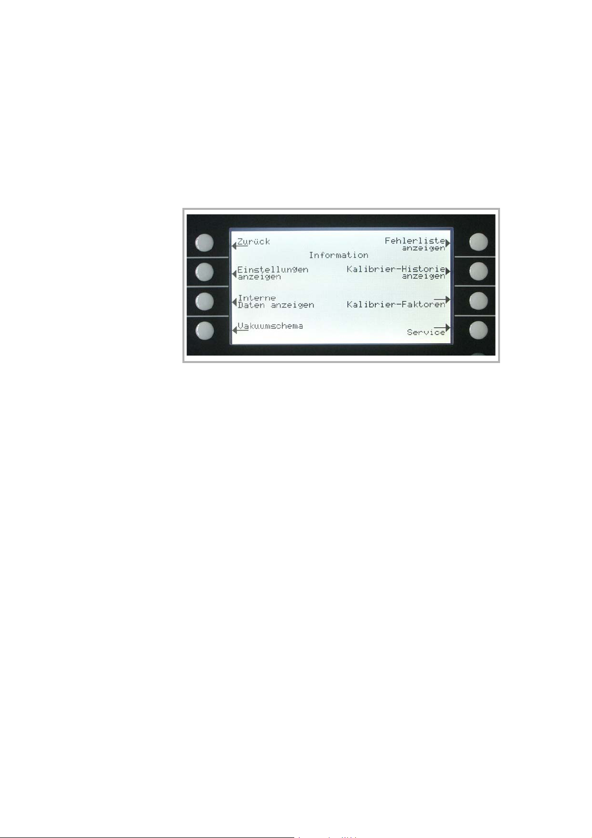
Operation
3.11 Information
Main menu > Information
The Information Menu Fig.31 enables submenus to select different kinds of information belonging to the PHOENIX L300i.
Fig. 31 Display: Information Menu
Softkey 2: View settings
The current settings will be displayed on 5 pages, e.g. trigger levels, test
leak mass, date and time.
Softkey 3: View internal data
Information on measured internal data is provided on 10 screens.
Softkey 4: Vacuum diagram
The vacuum diagram of the PHOENIX L300i is shown. Here you can see
which valves are opened or closed momentarily. See chapter 4.1.1
Softkey 5: View error list
The list of occurred errors and warnings will be displayed. See chapter
8.2.
Softkey 6: Calibration history
The carried out calibrations will be listed.
Softkey 7: Calibration factors
The calibration factors for the different masses and the machine factor will
be displayed.
Softkey 8: Service
GA10218_002_C0 - 10/2016 - © Leybold GmbH
82
Page 83
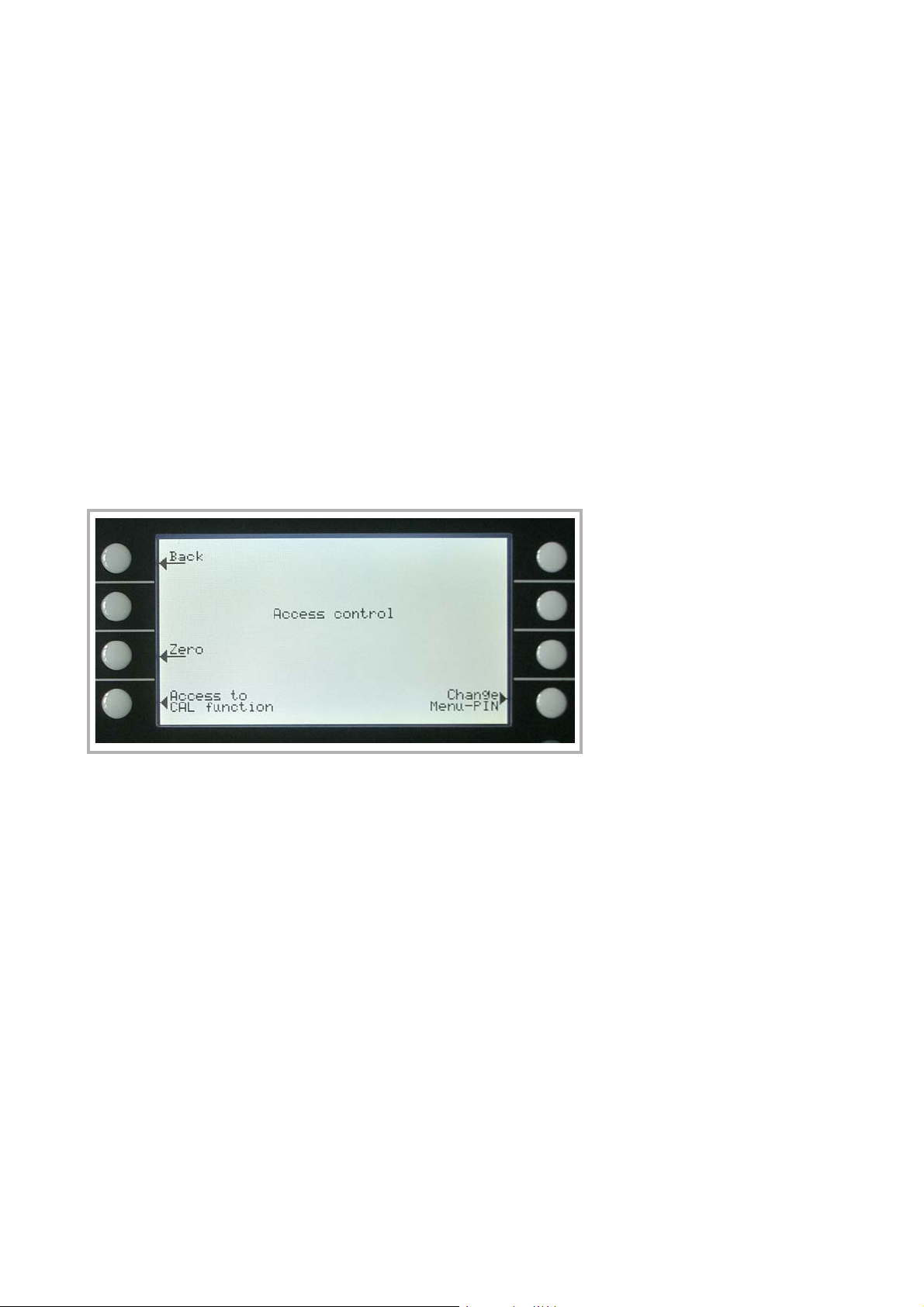
3.11.1 Service
Main menu > Information > Service
With the main menu special functions can be accomplished (e. g. manual switching
of the valves). The access to the service menu is protected by a PIN. This PIN is
not communicated with the delivery of the leak detector but after an adequate ser
vice training.
3.12 Access Control
Main menu > Access control
With this menu you can deny or allow access to specific functions of the PHOENIX
L300i.
Operation
-
Fig. 32 Display: Access Control Menu
Softkey 3 Zero
Settings of the zero function
Softkey 4: Access to CAL function
Settings for restriction of the CAL function
Softkey 8: Change Menu-Pin
Access to menu pin can be restricted
3.12.1 Zero
Main menu > Access control > Zero
This setting enables (respectively disables) the ZERO button at the control panel.
With „Zero at FINE“, the ZERO functions executes automatically as soon as the
measuring range FINE is reached for the first time after START. In this mode the
ZERO function also can be executed manually via the ZERO button.
GA10218_002_C0 - 10/2016 - © Leybold GmbH 83
Page 84

Operation
Softkey 3: Disable
ZERO button disabled
Softkey 5: ?
Help text
Softkey 6: Zero at FINE
When reaching the FINE mode and leak rate falls below trigger level 3 the
ZERO function is started automatically.
Softkey 7: Enable
Softkey ZERO is selectable. Default setting.
3.12.2 Access to CAL Function
Main menu > Access control > Access to CAl function
It can be selected whether the access to the calibration menu is restricted or not.
Softkey 3: Off
The calibration function is only available at the main menu. If the MenuPIN (See Chapter
tion. Default setting.
Softkey 5: ?
Help text
Softkey 7: ON
The calibration function is available at the main menu and in standby and
the measure mode.
3.12.3) is activated you need this PIN to start a calibra-
3.12.3 Change Menu-PIN
Main menu > Access control > Change Menu-Pin
The access to the menu can be restricted by entering or changing the personal
identification number (PIN). No PIN will be checked if 0000 is entered.
The default setting for the Pin is 0013.
Please refer to Numerical entries for the description of the entry.
3.13 Calibration
3.13.1 Introduction
The PHOENIX L300i can be calibrated in two different ways:
Internal calibration by means of a built-in test leak
or
external calibration by means of an additional test leak which then is attached to
the inlet port or the component under test.
During the calibration procedure the mass spectrometer is tuned to the maximum
GA10218_002_C0 - 10/2016 - © Leybold GmbH
84
Page 85

helium or hydrogen signal and this signal is referred to the known leak rate of the
internal or external test leak. Although the PHOENIX L300i is a very stable inst
rument a calibration is recommended every day with heavy use, or before using the
PHOENIX L300i from time to time, to make sure that ambient temperature changes
or dirt or other impacts don’t adulterate the measurements.
To get an optimized calibration the machine has to warm up at least 20 minutes
before use, otherwise a warning will come up which might be ignored.
3.13.2 The calibration Routines
The calibration routines can be started by pressing button CAL (Softkey 5) via 3
different locations:
main menu (Fig. 23)
standby mode (Fig. 12)
Operation
-
measurement mode (Fig. 10)
The access via standby mode or measurement mode can possibly be blocked (see
Chapter
Once the calibration mode is activated the user must choose between an internal
and an external calibration. Please press the corresponding Soft Key (
A calibration may be terminated at any time by pressing the Stop button or using
the Soft Key no. 1 (Cancel)
3.12.2). In this case the softkey is not labeled. Default: Access on.
Fig. 29).
Fig. 34.
3.13.3 Internal Calibration
Mass 4 must be selected (Default setting)
Press Softkey no 4 Fig. 29 to start the calibration. Once this procedure is started
the entire procedure is performed automatically. At the end (after about 25 s) a
visual and audio signal is released. Thereafter the unit is ready for further use.
GA10218_002_C0 - 10/2016 - © Leybold GmbH 85
Page 86
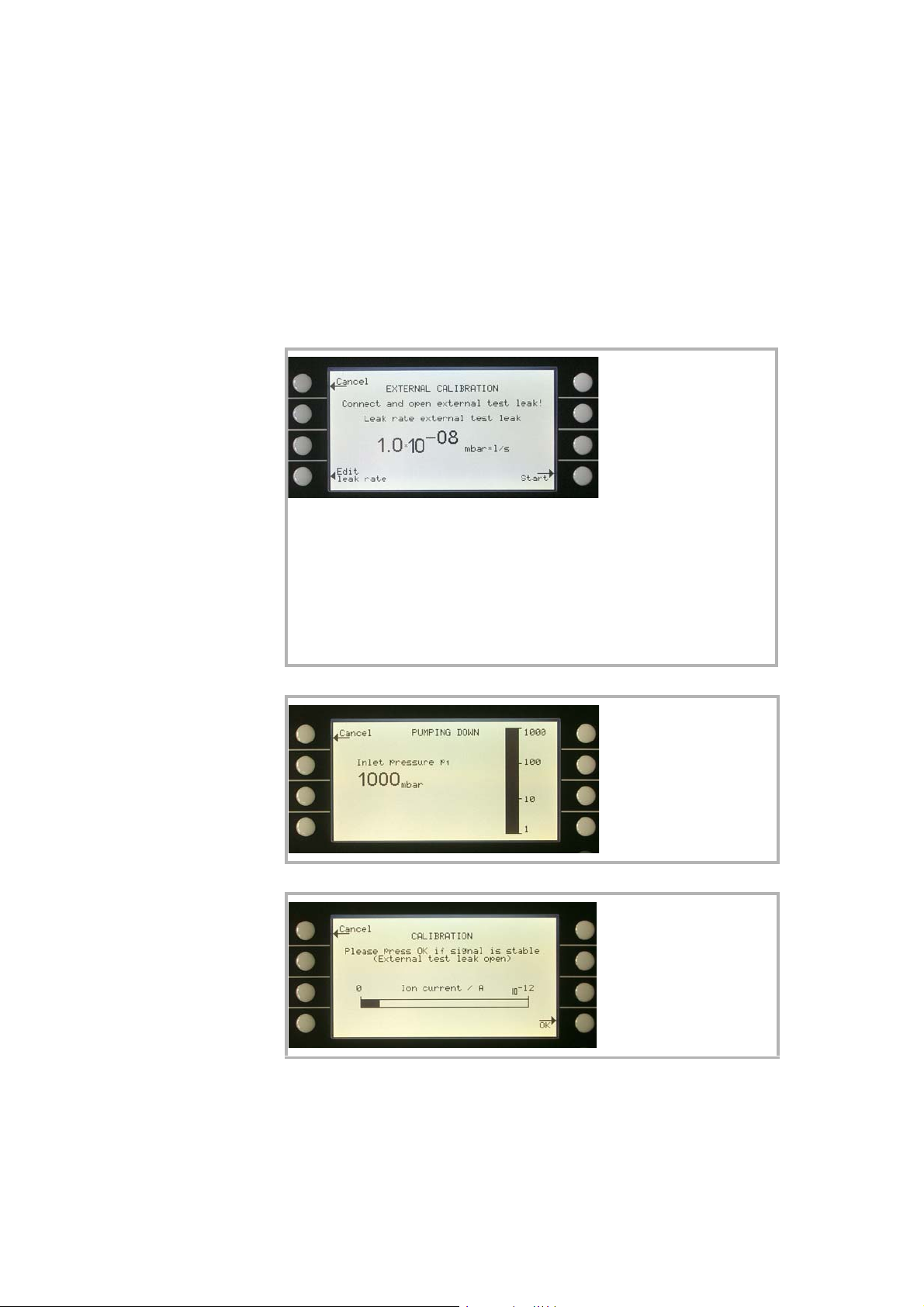
Operation
3.13.4 External Calibration
For an external calibration a test leak has to be attached to the part under test or
the inlet port directly depending on the application.
After External calibration (Fig. 29, Soft Key no. 8) has been chosen the following
messages are displayed and the described actions are required:
Make sure that the correct mass is selected.
Make sure that the test
leak is connected and
opened.
Check the leak rate printed on the test leak
and compare it with the leak rate at the dis
play. If the leak rates are not identical press
Edit leak rate (Soft Key no. 4) and correct the
value.
If the leak rates are okay press START (Soft
Key no. 8).
Fig. 33 Display: External Calibration, Step 1
Fig. 34 Display: External Calibration, Step 2
-
No action required.
The bargraph display
shows a signal which
must not vary much. If so
please press OK (Soft
Key no. 8).
Fig. 35 Display: External Calibration, Step 3
GA10218_002_C0 - 10/2016 - © Leybold GmbH
86
Page 87
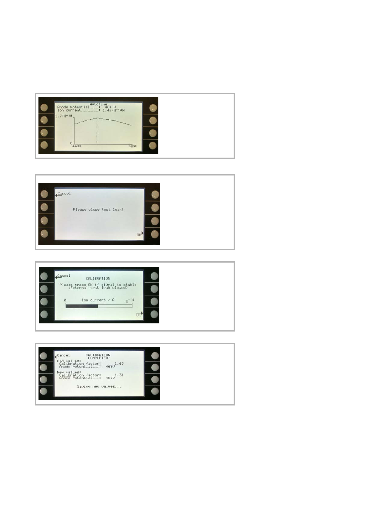
Fig. 36 Display: External Calibration, Step 4
Operation
No action required.
The bargraph display
shows a signal which
must not decrease any
more. There might be a
small fluctuation which is
okay. If so please press
OK (Soft Key no. 8).
Fig. 37 Display: External Calibration, Step 5
Fig. 38 Display: External Calibration, Step 6
Fig. 39 Display: External Calibration, Step 7
When the signal is stable
confirm with o.k.
The PHOENIX L300i
shows the old and the
new calculated calibration
factor.
GA10218_002_C0 - 10/2016 - © Leybold GmbH 87
Page 88

Operation
Factor of calibration/Range
of values
Factor of calibration - Range of values
To avoid a faulty calibration the factor of calibration is tested for plausibility at the
end of the calibration routine.
When the new factor of calibration is not considerable higher or lower (<factor 2)
than the previous factor of calibration the new factor will be accepted
automatically. When the new factor of calibration diverges stronger from the pre
vious factor the user can decide if he wants to accept it anyway (e.g. after changing
the system configuration) or not (e.g. because of maloperation).
When calibration is started via SPS or RS232 no testing for plausibility is occuring.
When calibrating internal it is also monitored if the newly calculated factor of calibration is higher than 10 or lower than 0.1. In this case a warning (see W81 resp.
W82 in Chapter
3.14 Switching Off/Shutting Down
The PHOENIX L300i can be switched off any time by using the mains switch. The
turbo pump will be decelerated automatically. It is recommended to put the leak
detector into standby and vented mode. Approximately after 30 seconds the turbo
pump is decelerated sufficient to move the PHOENIX L300i.
5.2.) is displayed and the calibration will be interrupted.
-
GA10218_002_C0 - 10/2016 - © Leybold GmbH
88
Page 89

4 Maintenance
4.1 Safety Information
Electrical hazards
During all maintenance and connection work, make sure that the mains cable have
been reliable disconnected and do not carry a mains voltage.The leak detector
must only be used in with the hoods closed. The electrical connections must only
be provided by a trained electrician as specified, for example, by the regulations EN
50110-1.
4.2 Maintenance Intervals
Maintenance work should be done on the PHOENIX L300i as required. This work
will normally be limited to exchanging the oil in the Trivac D2,5E rotary vane pump
and the built in air and oil filters.
As a preventive measure it is recommended that you check the rotary vane pump
once a month. Here note should be taken of the oil level and the colo ur of the oil.
Maintenance
Caution
Only Leybonol LVO 310 (Cat. no. L31001) must be used in the TRIVAC D2,5E in
the PHOENIX L300i.
The monthly interval for the check is just a nominal period. If the PHOENIX L300i is
used heavily, in particular in sniffer mode, then this check should be performed
more frequently. The rotary vane pump is located on the side of the mechanical
section at the bottom of the leak detector.
4.3 Service at Leybold
Whenever you send us in equipment, indicate whether the equipment is
contaminated or is free of substances which could pose a health hazard. If it is
contaminated, specify exactly which substances are involved. You must use the
form we have prepared for this purpose.
A copy of this form has been reproduced at the end of these Operating Instructions: Declaration of contamination for Compressors, Vacuum pumps and Components. Another suitable form is available from www.leybold.com Documentation - Download Documents.
Attach the form to the equipment or enclose it with the equipment.
This statement detailing the type of contamination is required to satisfy legal requirements and for the protection of our employees.
We must return to the sender any equipment which is not accompanied by a
contamination statement.
Before shipping fit the yellow screw-on seals on to the connections EXHAUST and
GAS BALLAST.
Contamination
Form
GA10218_002_C0 - 10/2016 - © Leybold GmbH 89
Page 90
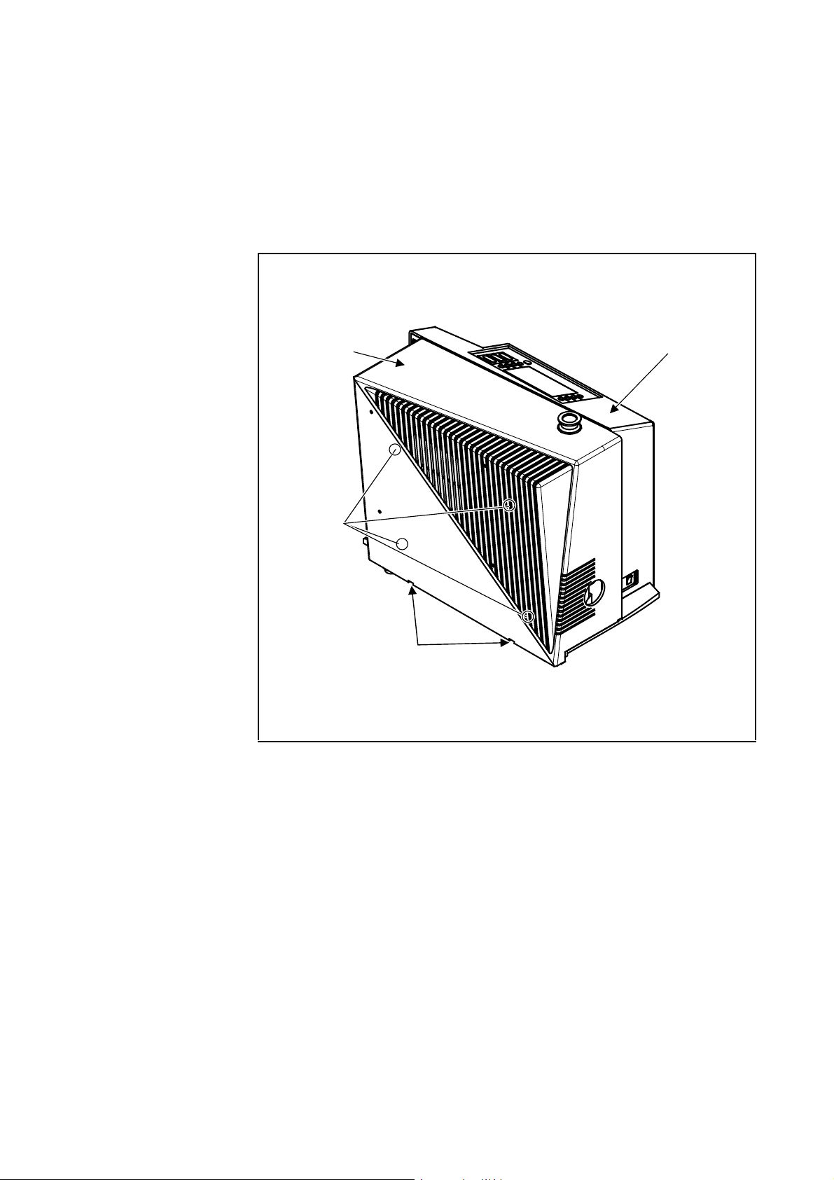
Maintenance
1
2
3
4
4.4 Maintenance Work
4.4.1 Opening of the PHOENIX L300i
Fig. 40 Back view of the PHOENIX L300i
1: Openings for removal of the cover for the mechanical section
2: Four screws for loosening the cover for the electronics section.
3: Mechanical cover
GA10218_002_C0 - 10/2016 - © Leybold GmbH
90
4: Electronic cover
To open the PHOENIX L300i please follow the next steps:
1. Switch the PHOENIX L300i off.
2. Pull the mains cord on the PHOENIX L300i.
3. Separate the PHOENIX L300i from other vacuum components at the test port.
Page 91
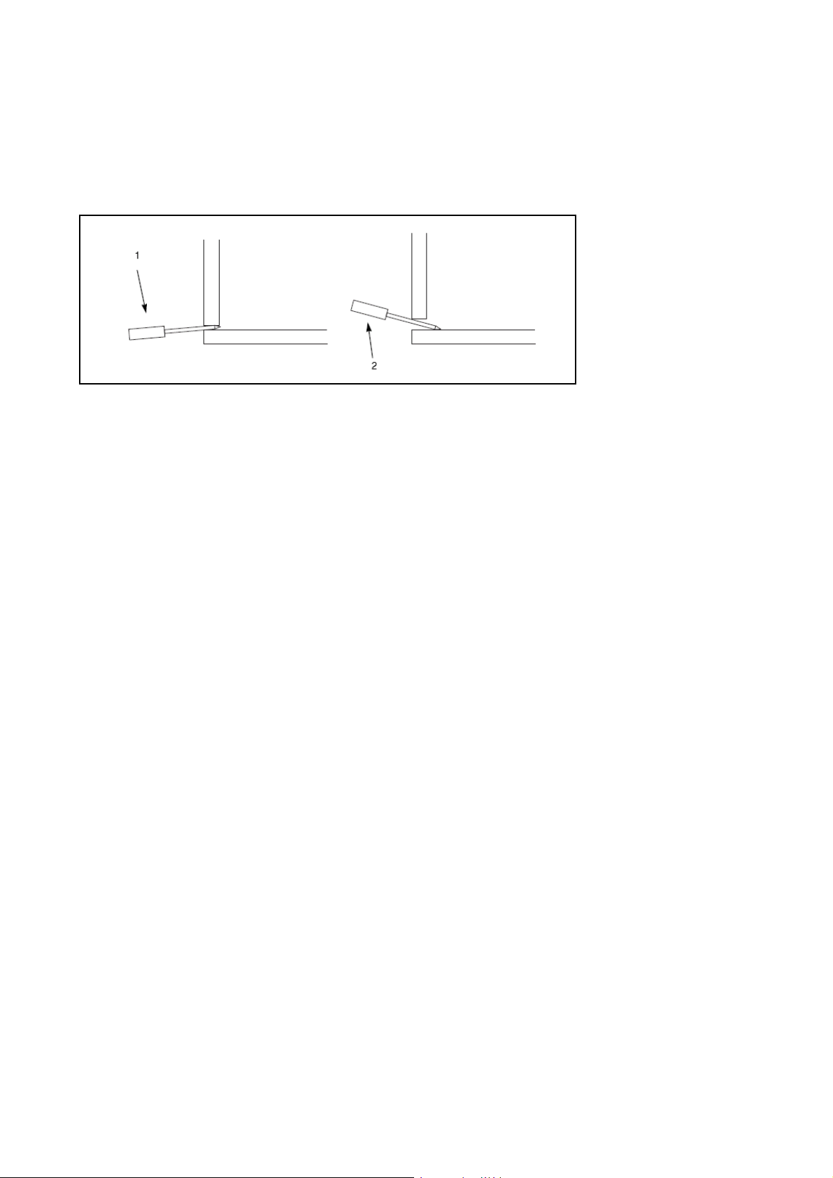
Fig. 41 Opening of the mechanical hood
4. Turn the PHOENIX L300i so that it is orientated in the same way as shown in Fig.
5. Use two flat blade screw drivers and insert these into the openings (Fig. 41) and
lever the cover for the mechanical section out at the bottom.
Maintenance
6. In doing so, the cover should be moved somewhat to the front by the downward
motion of the screwdrivers. The cover may be lifted up by the upwards motion of
the srew drivers so that the cover is disengaged completely.
7. Then pull the cover off the mechanical section up to its stop and remove it to the
front.
8. Removing the cover for the electronics section by removing the four Phillips
screws (
9. Pull the cover over the electronics section back to the rear and place it aside.
10. After completion of all maintenance work put the electronic cover back in place
and screw it tighten. The cover of the mechanical section must engage properly
in the openings at the bottom.
Fig. 40/2).
4.4.2 Exchanging the Filter Mats
The filter mats have been built in to filter the dust out the air which is taken in. In
order to ensure that the filter mats will not throttle the air flow and so that sufficient
cooling is possible at all times, the filter mats should be cleaned or exchanged as
soon as these have attained a dark grey colo ur.
Filter mats are used at two places within the PHOENIX L300i:
a) at the ventilation slit of the electronic cover (only partly visible from the outside)
b) at the fan of the turbo molecular pump (only partly visible from the outside)
To exchange the filter mats remove the covers as described above.
Filter mat a.) these filter mats are screwed to the electronic cover. Unscrew the
screws and exchange the filter mats. (Cat. no. 20099026)
Filter mat b) This filter mat is fixed before the fan with a plastic bracket. Take of the
bracket and remove the filter, put on the bracket and fix it properly. (cat.- no.
200001366)
Under certain circumstances a dirty mat may be cleaned by shaking the dust out or
GA10218_002_C0 - 10/2016 - © Leybold GmbH 91
Page 92
Maintenance
by using a vacuum cleaner so that the filter mat can be used again.
In the ventilation line is a dust filter installed. This filter has to be cleaned or changed
when using in dirty environment (cat.-no. 200000683).
4.4.3 Exchanging the Oil
Remove the cover of the mechanical section as described in Chapter 4.4.1.
Caution
Electrical hazards
During all maintenance and connection work, make sure that the mains cable have
been reliable disconnected and do not carry a mains voltage.The leak detector
must only be used in with the hoods closed. The electrical connections must only
be provided by a trained electrician as specified, for example, by the regulations EN
50110-1.
When the pump has been pumping hazardous substances, determined the kind of
hazard first and ensure that suitable safety precautions are taken.
Observe all safety regulations
When disposing of waste oil you must observe the applicable regulations for the
safety of the environment.
The oil change procedure are described in the corresponding Operating Instructions GA 01.601 and these must be followed closely.
As already stated before only Leybonol LVO (Cat. no. L31001) must be used for
the Trivac D 2,5E pump in the PHOENIX L300i.
After completion of all maintenance work the cover of the mechanical section must
engage properly in the openings at the bottom.
4.4.4 Cleaning
The housing of the PHOENIX L300i is made of painted plastic parts. Thus for the
purpose of cleaning, only such agents should be used which are generally also
used for other painted or plastic surfaces (mild household cleaning agents, for
example). Normally a moistened peace of cloth will do. Never use any solvents
which are capable of dissolving paint (like acetone, toluol, etc.).
A soft brush or a vacuum cleaner is recommended for cleaning the ventilation slits.
4.4.5 Exchanging the Fuses
Caution
GA10218_002_C0 - 10/2016 - © Leybold GmbH
92
Before exchanging the fuses you must disconnect the mains cord.
1. Switch the PHOENIX L300i off.
2. Pull the mains cord off the PHOENIX L300i.
3. Use a screwdriver to fold out the lid of the mains socket from the right (the mains
switch is not affected by this).
4. The fuses can be removed by pulling the drawers out which are marked by the
arrows. When reinserting these make sure that the arrows point downwards.
5. In any cases two fuses of the same rating must be inserted. The required mains
fuses are: T 10A slow blow (20x5mm dial.) for 100V...230V.
Page 93

6. After having exchanged the fuse (s) press the lid of the mains socket firmly back
on.
7. Insert the mains cord into the PHOENIX L300i and switch the instrument on.
Beside these mains fuses several internal circuits are fused separately. These fuses
are listed in the following table. See also
In order to exchange these fuses you must proceed as follows:
1. Switch the PHOENIX L300i off
2. Pull the mains cord on the PHOENIX L300i
3. Remove the cover for the mechanical and electronics section according to
Chapter.
4. Exchange fuses
Fig. 42.
Maintenance
As can be seen in Fig. 42, fuses 1, 2, 3 and 4 are located on the MSV board, fuses
5 and 6 on the I/O board and the fuses 7, 8, 9 and 10 are located on the wiring
backplane under the MSV board.
5. Finally re-install the covers for the electronics and mechanical section in the
reverse order.
No 1 F1 on MSV
Fuse rating: T 2A
No 2 F2 on MSV Not in use.
No 3 F3 on MSV
Fuse rating: T 1A
No 4 F4 on MSV
Fuse rating: M 0,032A
24 V system voltage of the mass spectrometer supply.
Loosen control panel (two Phillips screws). Loosen the
panel which holds the MSV board in place (two Phillips
screws).
Pull the MSV board (the board at the back) up to the
top. For this insert a screwdriver into the two recesses
at the sides (top) one after the other and lever the MSV
board out by resting the screwdriver on the STE
board.
For generating 24 V for DCDC-converter
(+/- 15V / 5 V)
Fuse for the anode voltage
No 5 F1 on I/O board
Fuse rating: T 0,8A
No 6 F2 on I/O board
Fuse rating: T 0,2A
No 7 F 1 on MB
Fuse rating: T 0,8A
No 8 F 2 on MB
Fuse rating: T 4A
Protects the 24 V supply carried by the option socket
Protects the selectable 24 V for RS 232 Interface.
Supply voltage for the remote control
Supply voltage 24 V for I/O board.
GA10218_002_C0 - 10/2016 - © Leybold GmbH 93
Page 94
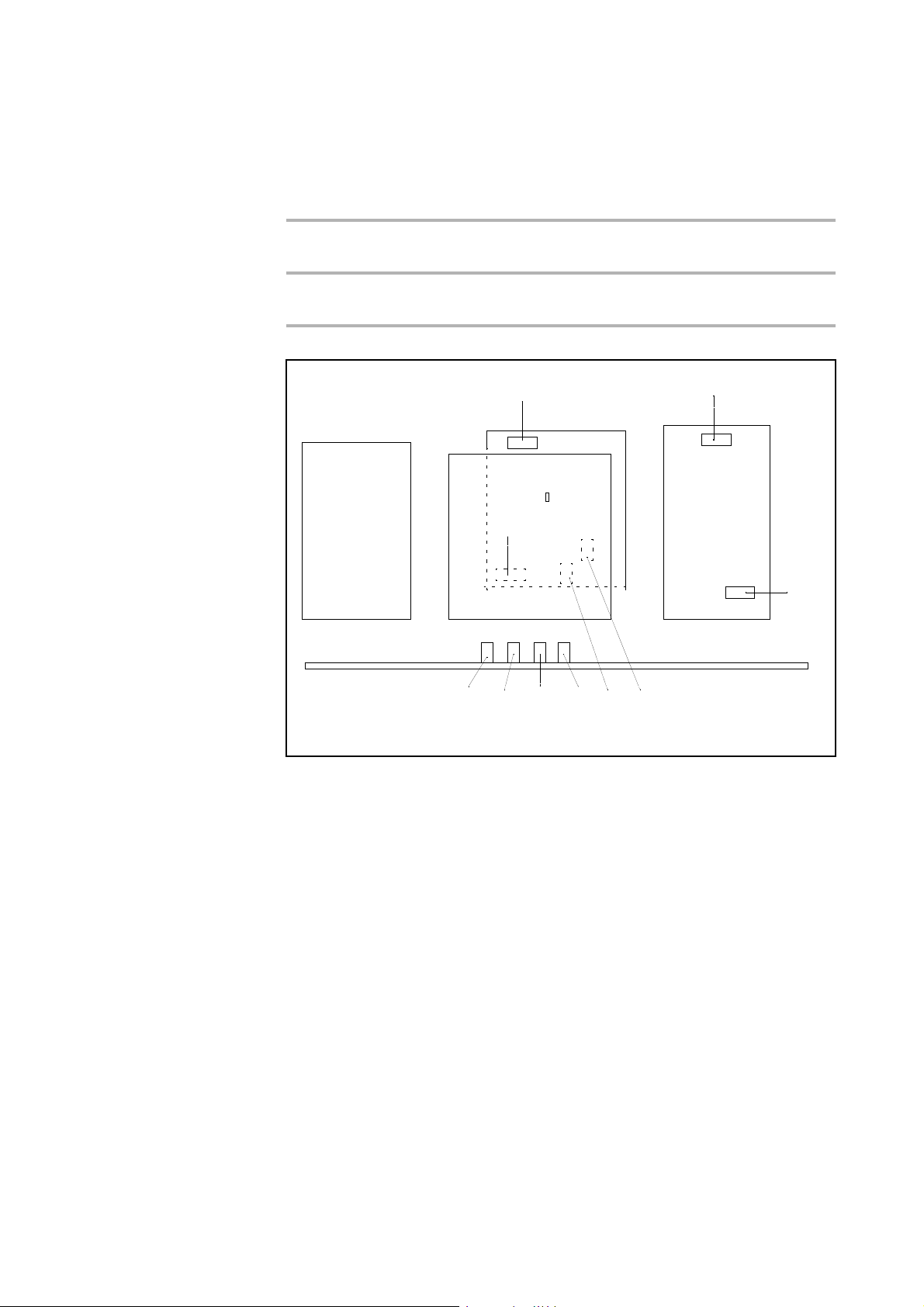
Maintenance
TMP-Wandler
TDS
MSV
STE Karte
I/O Karte
3
6
5
1
2478910
No 9 F 3 on MB
Fuse rating: T 0,8A
No. 10F 4 on MD
Fuse rating: T 8A
Supply voltage 24 V for fans and motor relay.
Protection for the fore vacuum pump.
Fig. 42 Assembly fuses
4.4.6 Exhaust Oil Filter
After using the PHOENIX L300i for a longer time there can be oil accumulated from
the pump. In this case please do the following:
1. Switch off the PHOENIX L300i.
2. Remove the mechanical cover according to Chapter 4.4.1.
3. The oil filter is located besides the rotary vane pump.
4. Unscrew the plexiglas cabinet (direction is shown by an arrow on the filter).
5. Clean or replace the filter (cat-no. 20028656)
6. Screw back the plexiglas cabinet hand tight.
7. Check the oil level of the rotary vane pump and fill it up when necessary (see
instructions for rotary vane pump).
8. Finally re-install the cover for the mechanical section.
4.4.7 Turbo Molecular Pump
For the Leybold turbo molecular pump TW 70 LS it is recommended to change the
bearings after 20.000 running hours. For details please refer to the corresponding
manual of the turbo pump (GA 05156.0101) or contact your local Leybold service.
GA10218_002_C0 - 10/2016 - © Leybold GmbH
94
Page 95

4.5 Calibrated Leak TL7
The Calibrated leak TL7 with the helium reservoir is used for alignment of the mass
spectrometer in the PHOENIX L300i as well as for calibration the leak rate indica
tion.
It is equipped with a solenoid valve which is actuated via the control electronics of
the PHOENIX L300i.
4.5.1 Technical Data
Maintenance
-
Nominal calibration range
Tolerance of nominal calibration range +/- 15 %
Temperature coefficient < 0,5 %/°C
Leak type Capillary
Filling Helium
4.5.2 Factory Inspection
Calibrated leaks are not subject to wear and the Helium loss of the calibrated leak
TL7, being less than 2
change over years due to external influences. A factory inspection is, therefore,
advisable once a year.
A test certificate, if required for the Helium calibrated leak, can be obtained from
our Cologne Works. In that case, the calibrated leak should be forwarded to us and
will be returned inspected and recertified with the test certificate against charge.
The helium flow stated on the main label is the actual leak rate of the calibrated
leak.
% per year, is negligible. Nevertheless, the leak rate may
10-7 mbarl / s
GA10218_002_C0 - 10/2016 - © Leybold GmbH 95
Page 96

Troubleshooting
5 Troubleshooting
The PHOENIX L300i is equipped with comprehensive self-diagnostic facilities. If an
error or warning condition is detected it is indicated via the LC display to the opera
tor.
An audio signal is generated when an error or warning occurs. The frequency
changes every 400
stands out well from ambient noises normally encountered.
Error and warning messages are logged and can also be displayed at a later time
through the menu information (Please refer to Chapter
5.1 Hints for Troubleshooting
Warnings will be indicated
- when the PHOENIX L300i detects an abnormal condition or
- when it wants to remind the operator of something (e.g. a request for calibration
or a service timer has expired).
-
ms from 500 Hz to 1200 Hz and vice versa so that the signal
Information.)
The PHOENIX L300i will indicate a message on the LC display and will remain in
the standby or the measurement mode.
Warning messages will remain on the LC display until the warning has been
acknowledged by pressing „OK“ (Key no. 8). After that the PHOENIX L300i can be
used again (possibly with some restrictions). As long as a warning status exists the
status line shows a warning triangle.
Errors are events which force the PHOENIX L300i to interrupt its measurement
operations. In this case the PHOENIX L300i closes all valves except valve 2a
(standby mode).
Error messages remain on the LC display until the message has been
acknowledged by pressing „Restart“ (key no. 8). After that, the PHOENIX L300i
restarts with a new run-up procedure. In some cases it may be helpful to check
some settings or measured values before the PHOENIX L300i restarts. Therefore it
is also possible to press „Menu“ (key no. 4 or Menu key) to enter the PHOENIX
L300i menu. After leaving the menu the same error message will be displayed
again.
Under extreme conditions (unknown software errors, excessively high
electromagnetic interference levels) the built-in „watchdog“ circuit will prevent
uncontrolled operation of the PHOENIX L300i. This watchdog will cause the PHO
ENIX L300i to restart. After having done so, the instrument will be running in the
standby mode. No error message will be output.
-
5.2 List of Errors & Warnings
The following pages contain a list of all errors and warnings displayed at the control
panel. Warning messages are indicated by numbers with a leading W. Error
messages are indicated by numbers with a leading E.
GA10218_002_C0 - 10/2016 - © Leybold GmbH
96
Page 97

Troubleshooting
No. Displayed Message Description and possible solutions
W14 Exhaust oil filter service interval
expired
W17 Fore pump service interval expi-
red!
W21 EEPROM write time out EEPROM defective
W22 EEPROM parameter queue over-
flow
E23 24V for external output 1 is too
high.
E24 24V for external output 1 is too
low.
E25 Lowered valve voltage too low
(<
7V).
E26 24V for external output 2 is too
low.
E27 24V for external output 3 is too
low.
The chosen service interval for the exhaust oil filter is expired.
Control and/or replace the exhaust filter insert.
The service interval for the fore pump is expired.
Service the fore pump
MC 68 defective
Software problem, please contact Leybold service.
The 24 V voltage for the external output 1 is too high
Check if an external voltage has been applied to the 24V output.
The 24 V voltage for the external output 1 is too low.
Fuse F2 on the wiring backplane has blown
I/O board is faulty.
MC 68 defective.
The 24 V voltage for the external output 2 (RS232) is too low.
Fuse F2 on the I/O board has blown
The 24 V voltage for the external output 3 (optional) is too low.
Fuse F1 on the I/O board has blown
W28 Real time clock reset! Please
enter date and time!
E29 24V supply for fans is too low
(<
20V).
E30 24 V of the remote control is too
low (<
20V).
W31 The offset voltage of the preamp-
lifier is too high (> 5mV).
W32 Preamplifier temperature is too
high (>
W33 Preamplifier temperature is too
low (<
E34 24V voltage at MSV board is too
low!
65°C).
2°C).
Battery at MC68 is discharged or faulty.
MC68 had been replaced.
Fuse F1 on wiring backplane has blown.
Fuse F1 on the I/O-board has blown.
The preamplifier is faulty.
Ambient temperature is too high.
Air filter dirty.
Ambient temperature is too low.
Temperature sensor is faulty.
Signal MVPZN on the MSV board is active. 24 V signal voltage is too low, U <
18.3 V.
– Fuse F1 on the MSV board has blown.
– Reference voltage UREF on the MSV board XT7/1 is too high, U > 5 V.
– DC/DC converter on the MSV board is defective.
– 24V power supply voltage of the main power supply is defective or
stressed to much.
GA10218_002_C0 - 10/2016 - © Leybold GmbH 97
Page 98

Troubleshooting
No. Displayed Message Description and possible solutions
E35 Anode-cathode voltage is too
high!
E36 Anode-cathode voltage is too
low.
E37 Suppressor voltage reference
value too high!
E38 Suppressor potential too high! Suppressor potential is higher than 363V.
E39 Suppressor potential is too low. Suppressor potential is lower than 297V.
E40 The anode potential exceeds its
nominal value by over 10%!
Anode-cathode voltage is > 130 V
MSV board is faulty.
Anode-cathode voltage is < 30 V.
MSV board is faulty.
Fuse F4 on MSV board has blown.
Signal MFSZH on MSV board is active. Suppressor signal command variable
is too high.
– Suppressor voltage has a short circuit.
– MSV is faulty.
MSV board is faulty.
MSV board is faulty.
The actual anode potential exceeds its nominal value by 10%. The nominal
value can be displayed in the service menu.
MSV is faulty.
MC 68 is faulty
E41 The anode potential has dropped
below its nominal value by over
10%!
E42 Nominal value of the anode
potential is too high!
E43 Cathode current is too high!
MSV Cat-Heater >>
E44 Cathode current is too low! Signal MPKZN on MSV board is active. Cathode current is too low,
W45 Emission for cathode 1 can not
be switched on!
The actual anode potential has dropped below its nominal value by 10%. The
nominal value can be displayed in the service menu.
MSV is faulty.
MC 68 is faulty.
Signal MFAZH on MSV board is active.
Anode voltage has been short circuited.
Nominal value of the anode voltage is too high. Anode voltage is limited to
about 1,200 V.
Signal MPKZH on MSV board is active. Cathode current is too high, I > 3.6
A.
MSV is faulty.
I < 0.2 A.
MSV is faulty.
Faulty ion source connector or cable.
Signal MSIBE on MSV board is not active. Emission for cathode 1 can not be
switched on. PHOENIX L300i switches to cathode 2. Please order a new ion
source.
GA10218_002_C0 - 10/2016 - © Leybold GmbH
98
Cathode 1 is defective
MSV board is defective
Page 99

Troubleshooting
No. Displayed Message Description and possible solutions
W46 Emission for cathode 2 can can
not be switched.
E47 Emission for both cathodes can
not be switched on!
E48 Anode heater is faulty! Signal MSAFD on MSV board is active. Anode heater fuse has blown.
E50 No communication with turbo
pump converter.
E51 Unknown TMP error The frequency converter Turbo Drive S indicates an unknown error code.
Signal MSIBE on MSV board is not active. Emission for cathode 2 can not be
switched on. PHOENIX L300i switches to cathode 1. Order a new ion
source.
Cathode 2 is defective.
MSV board is defective.
Signal MSIBE on MSV board is not active. Emission can not be switched on.
Exchange the cathode by changing the ion source. After having exchanged
the ion source it must be possible to switch on both cathodes manually via
the service menu.
Replace ion source.
MSV board is defective.
Replace fuse F2 on the MSV board.
Clock from the frequency converter has failed. No communication to the frequency converter.
Fuse F4 on the wiring backplane has blown.
Drive electronics Turbo Drive S is defective.
Inform Leybold service
E52 TMP frequency is too low! TMP frequency is too low!
Frequency converter is faulty.
Turbo molecular pump is faulty.
W53 Temperature at electronic unit is
too high (>59°C)
Temperature at electronic unit is
E54
too high (>60°C).
W55 Temperature at electronic unit is
too low (<
E56 Inlet pressure p1 too low! Output voltage Pirani P1 U < 0,27 V.
E58 fore vacuum pressure p2 too low! Output voltage Pirani P2 U < 0,27 V.
2°C)
Ambient temperature too high.
Ventilation failure.
Air filter dirty and have to be changed.
Ambient temperature is too high.
Internal ventilation has failed.
Air filters are dirty and must be exchanged.
The temperature sensor on the wiring plane indicates T < 2 °C. Run-up time
for the fore vacuum pump will be longer.
Temperature sensor is faulty.
Ambient temperature is too low.
Pirani sensor P1 is defective.
Pirani electronics on the I/O board is defective.
Pirani sensor P2 is defective.
Pirani electronics on the I/O board is defective.
GA10218_002_C0 - 10/2016 - © Leybold GmbH 99
Page 100

Troubleshooting
No. Displayed Message Description and possible solutions
E60 p2>10mbar after 5 minutes since
power on
E61 Emission fail. Emission could not be switched on. MSV subassembly indicates a fault.
W62 Flow through capillary to low. In the sniffer mode the intake pressure of the sniffer line is controlled. If the
W63 Capillary broken In the sniffer mode the intake pressure of the sniffer line is controlled. If the
Run-up time of the fore vacuum pump is too long.
Fore pump is faulty.
Valve V2 does not open.
Leak in the high vacuum system.
MENB emission current not within range.
MSV board is defective.
Both cathodes are defective, replace ion source.
pressure falls below the minimum limit, the flow through the capillary is too
low (contamination) or the capillary is blocked (foreign objects, particles).
The minimum limit can be set by the menu. Default value is 0.05 mbar.
Filter in the tip is clogged.
pressure exceeds the maximum limit, the flow through the capillary is too
high (no leak tightness, broken capillary).
The maximum limit can be set by the menu. Default value is 0,15 mbar.
The capillary is broken or has been torn off.
E64 TMP error: Nominal speed has
been exceeded by over 10%
E65 TMP error: Pass through time
exceeded
E66 TMP error: Bearing temperature
too high (>67°C)
E67 TMP error: Short circuit in TMP-
motor or connecting cable
Nominal speed of the pump has been exceeded by over 10%
EMC problems: Check connecting cable, insert it properly. Switch the power
supply voltage off and then on again.
Turbo.Drive S faulty: Inform Leybold Service
Max. time for passing through the critical frequencies has been exceeded.
Fore vacuum or high-vacuum pressure to high: Reduce the inlet pressure of
the PHOENIX L300i
Bearing defective: Inform Leybold service for repair
Max. bearing temperature has been exceeded
Fore vacuum or high-vacuum pressure to high: Reduce the inlet pressure of
the PHOENIX L300i
Fan defective: Replace the fan
Ambient temperature too high: Feed cooler air to the PHOENIX L300i
Bearing defective: Inform Leybold service for repair
Short circuit in the pump’s motor or the connecting cable
Check to see if the connecting cable is undamaged, exchange if required.
Inform Leybold service in case of short circuit in TMP motor
GA10218_002_C0 - 10/2016 - © Leybold GmbH
100
 Loading...