

Page 1

RS232 User Guide
Page | 1
Planar Simplicity Series 4K Displays
Simplicity Series 4K Displays RS232 User Guide
020-1344-00D
SL4364K
SL5064K
SL5564K
SL6564K
SL7564K
SL8664K
Page 2

Simplicity Series 4K Displays RS232 User Guide
020-1344-00D
Page | 2
Copyright © October 2019 by Leyard Optoelectronics Co., Ltd. and Planar Systems, Inc.
All rights reserved.
This document may not be copied in any form without permission from Leyard or Planar. Information
in this document is subject to change without notice.
Trademark Credits
Windows™ is a trademark of Microsoft Corp.
All other companies are trademarks or registered trademarks of their respective companies.
Disclaimer
The information contained in this document is subject to change without notice. Leyard and Planar
Systems, Inc. makes no warranty of any kind with regard to this material. While every precaution has
been taken in the preparation of this manual, the Company shall not be liable for errors or omissions
contained herein or for incidental or consequential damages in connection with the furnishing,
performance, or use of this material.
Warranty and Service Plans
Planar warranty and service plans will help you maximize your investment by providing great support,
display uptime, and performance optimization. From post-sale technical support, to a full suite of
depot services, our services are performed by trained employees. When you purchase a Planar
product, you get more than a display; you get the service and support you need to maximize your
investment. To find the latest warranty and service information regarding your Planar product, please
visit http://www.planar.com/support or http://www.leyard.com/en/support/
Part Number: 020-1344-00D
Page 3

Page | 3
Table of Contents
Introduction ............................................................................................................................. 7
1. Purpose ............................................................................................................................. 7
2. Definitions, Abbreviations and Acronyms ........................................................................... 7
Command Packet Format ..................................................................................................... 8
3. Physical Specifications ...................................................................................................... 8
4. Communication Procedure ................................................................................................ 9
5. Command Format .............................................................................................................. 9
System .................................................................................................................................... 10
6. Communication Control ................................................................................................... 10
6.1 Message Report ......................................................................................................10
7. Monitor Information .......................................................................................................... 11
7.1 Model Number, FW Version, Build Date Message Get ............................................11
7.2 Model Number, FW Version, Build Date Message Report .......................................11
General ................................................................................................................................... 12
8. Power State ..................................................................................................................... 12
8.1 Power State Get ......................................................................................................12
8.2 Power State Report .................................................................................................12
8.3 Power State Set ......................................................................................................12
9. IR Remote Control Lock Functions .................................................................................. 13
9.1 IR Remote Lock Status Get .....................................................................................13
9.2 IR Remote Lock Status Report ................................................................................13
9.3 IR Remote Lock Status Set .....................................................................................14
9.4 Keypad Lock Status Get ..........................................................................................14
9.5 Keypad Lock Status Report .....................................................................................14
9.6 Keypad Lock Status Set ..........................................................................................15
10. Power State at Cold Start ................................................................................................ 16
10.1 Power State at Cold Start Get ..........................................................................16
10.2 Power State at Cold Start Report ................................................................ .....16
10.3 Power State at Cold Start Set ...........................................................................17
Input Sources ........................................................................................................................ 18
11. Input Source .................................................................................................................... 18
11.1 Input Source Set ..............................................................................................18
12. Current Source ................................................................................................................ 19
Simplicity Series 4K Displays RS232 User Guide
020-1344-00D
Page 4

Table of Contents
Simplicity Series 4K Displays RS232 User Guide
020-1344-00D
Page | 4
12.1 Current Source Get ..........................................................................................19
12.2 Current Source Report .....................................................................................19
Video ....................................................................................................................................... 20
13. Video Parameters ............................................................................................................ 20
13.1 Video Parameters Get ......................................................................................20
13.2 Video Parameters Report .................................................................................20
13.3 Video Parameters Set ......................................................................................21
13.4 Color Temperature Get ....................................................................................21
13.5 Color Temperature Report ................................................................................22
13.6 Color Temperature Set .....................................................................................22
13.7 Color Parameters Get ......................................................................................23
13.8 Color Parameters Report ..................................................................................23
13.9 Color Parameters Set .......................................................................................24
14. Zoom Mode ..................................................................................................................... 25
14.1 Zoom Mode Get ...............................................................................................25
14.2 Zoom Mode Report ..........................................................................................25
14.3 Zoom Mode Set ................................................................................................26
Audio ....................................................................................................................................... 27
15. Volume ............................................................................................................................ 27
15.1 Volume Get ......................................................................................................27
15.2 Volume Report .................................................................................................27
15.3 Volume Set.......................................................................................................28
16. Volume Limits .................................................................................................................. 29
16.1 Volume Limits Get ............................................................................................29
16.2 Volume Limits Report .......................................................................................29
16.3 Volume Limits Set ............................................................................................30
17. Audio Parameters ............................................................................................................ 31
17.1 Audio Parameters Get ......................................................................................31
17.2 Audio Parameters Report .................................................................................31
17.3 Audio Parameters Set ......................................................................................31
Miscellaneous ....................................................................................................................... 32
18. Operating Hours .............................................................................................................. 32
18.1 Miscellaneous Info Get .....................................................................................32
18.2 Miscellaneous Info Report ................................................................................32
19. Auto Adjust ...................................................................................................................... 33
19.1 Auto Adjust Set ................................................................................................33
20. Serial Code ...................................................................................................................... 34
Page 5

Table of Contents
Simplicity Series 4K Displays RS232 User Guide
020-1344-00D
Page | 5
20.1 Serial Code Get ................................................................................................34
20.2 Serial Code Report ...........................................................................................34
Command Summary ............................................................................................................ 35
Page 6

Page | 6
Simplicity Series 4K Displays RS232 User Guide
020-1344-00D
Page 7

Page | 7
Introduction
1. Purpose
The purpose of this document is to explain in detail the commands and steps that
can be used to control a Planar Simplicity Series 4K display via RS232C.
2. Definitions, Abbreviations and Acronyms
ACK Acknowledge
NAK Not Acknowledge
NAV Not Available
ID Identification
Simplicity Series 4K Displays RS232 User Guide
020-1344-00D
Page 8
Page | 8
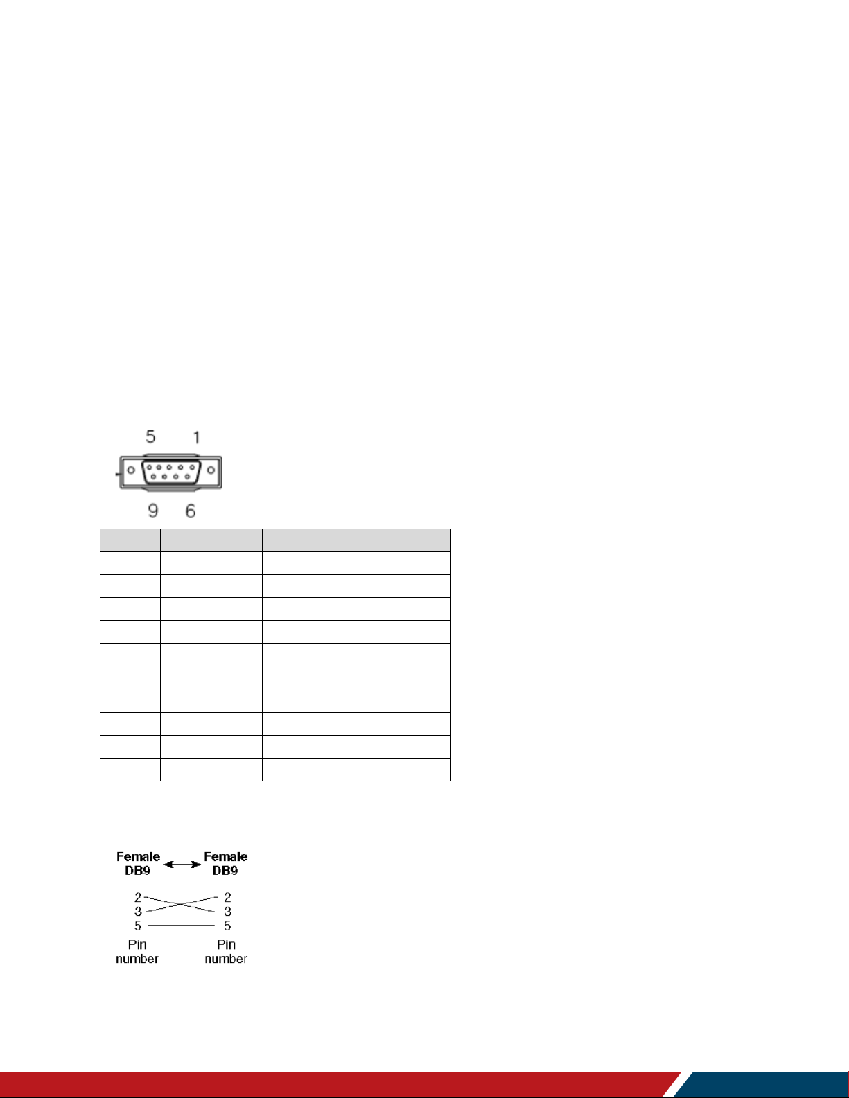
Pin#
Signal
Remark
1
NC
2 RXD
Input to LCD Monitor
3
TXD
Output from LCD Monitor
4
NC
5 GND
6
NC
7
NC
8
NC
9
NC
Frame
GND
Command Packet Format
3. Physical Specifications
1. Baud Rate : 9600
2. Data bits: 8
3. Parity : None
4. Stop Bit : 1
5. Flow Control : None
6. The Pin Assignments for DB9 male connector:
Male D-Sub 9-Pin (outside view)
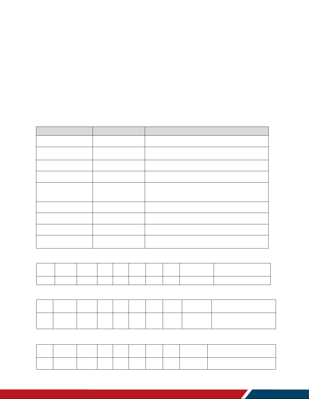
Note: Use a crossover cable (null modem) for connection to the host controller:
Planar Simplicity Series 4K displays use RXD, TXD and GND pins for RS232C control. For
RS232C cable, use the reverse type cable.
Simplicity Series 4K Displays RS232 User Guide
020-1344-00D
Page 9

Command Packet Format
Simplicity Series 4K Displays RS232 User Guide
020-1344-00D
Page | 9
Header
Monitor ID
Category
Code0
Code1
Length
Data
Control
Data[0]
…
Data[N]
Checksum
Number of Field
Name of Field
Description
Byte 1
Header
Header = 0xA6
Byte 2
Monitor ID
Monitor ID
Range: 1 ~ 255
Signal Mode: Display Address range from 1 to 255
Broadcast Mode: Display Address is 0, so no ACK
or Report is expected
Byte 3
Category
0x00
Byte 4
Code0 (Page)
0x00
Byte 5
Code1 (Function)
0x00
Byte 6
Length
Length has to be calculated in the following
way: Length = N + 3
Byte 7
Data Control
Data Control = 0x01 (fixed)
Byte 8 ~ Byte 44
Data[0] ~ Data[N]
This field can be also empty.
If not empty then the range of Data Size, N = 0 to
36.
Last Byte
Checksum
Checksum
Range = 0 to 255 (0xFF).
Algorithm: The EXCLUSIVE-OR (XOR) of all bytes
in the message except the checksum itself.
Checksum = [Header] XOR [Monitor ID] XOR …
DATA[0] … XOR DATA[N]
4. Communication Procedure
Send control commands from a host controller via the RS232 connection. Do not send a new
command until the previous command is acknowledged. However, if a response is not received
within 500 milliseconds, a retry may be triggered. Every valid command receives an ACK. A
command that is valid, but not supported in the current implementation, will be responded to
with NAV (Not Available). If the command buffer is corrupt, (transmission errors) the command
will be responded to with NAK. The display operates according to the received command. If the
command is a valid “Get” command, the display responds with the requested info. If the
command is a valid “Set” command allowed, the display performs the requested operation.
Note: For LAN control, the port number is 5000. To enable LAN support in standby mode, the
Power Save Mode setting must not be set to Low Power. Reference the Simplicity Series 4K
Displays User Guide for more information.
5. Command Format
The RS232 packet format:
In Detail:
Page 10
Page | 10
Number of Field
Name of Field
Description
Byte 1
Header
Header = 0x21
Byte 2
Monitor ID
Monitor ID
Range: 1 ~ 255
Byte3
Category
0x00
Byte4
Page
0x00
Byte5
MsgLen
Length of message plus Checksum code.
Calculate the length from Control Byte to
Checksum Byte.
Byte6
Control
0x01
Byte7
Data[0]
Copy the received Command code
Byte8~Byte8+(N-1)
Data[1]~Data[N]
Returned data associated with command code
Byte 8+N
Checksum
XOR of all byte in reply/report packet (except
checksum itself)
Header
Monitor ID
Category
Page
Length
Control
Data[0]
Data[1]
Checksum
Description
0x21
0x01
0x00
0x00
0x04
0x01
0x00
0x00
0x25
Command is well executed.
Header
Monitor ID
Category
Page
Length
Control
Data[0]
Data[1]
Checksum
Description
0x21
0x01
0x00
0x00
0x04
0x01
0x00
0x03
0x26
If the command code is
Data(0), the system will reply
“NAK.”
Header
Monitor ID
Category
Page
Length
Control
Data[0]
Data[1]
Checksum
Description
0x21
0x01
0x00
0x00
0x04
0x01
0x00
0x04
0x21
Checksum error- “NAV”.
Command Code Data(1)-“NAV”.
System
6. Communication Control
This defines the feedback command from the monitor to the host controller. When the device
receives a display command from the host controller the command reported to host controller
will be ACK, NAK or NAV.
Note: There is no reply message when the wrong ID address is used.
6.1 Message Report
Example ACK Reply: (Display Address 01)
Example NAK Reply: (Display Address 01)
Example NAV Reply: (Display Address 01)
Simplicity Series 4K Displays RS232 User Guide
020-1344-00D
Page 11

Simplicity Series 4K Displays RS232 User Guide
020-1344-00D
Page | 11
7. Monitor Information
Bytes
Bytes Description
Bits
Description
DATA[0]
0xA1 = Model
Number & FW
version of device with
Date- Get
Request the Model Number and FW version of the
device
DATA[1]
to
DATA[N]
Codes to request
0x00 = Model Number
0x01 = FW version
0x02 = Build Date
Bytes
Bytes Description
Bits
Description
DATA[0]
0xA1 = Model
Number & FW
version of device with
Date- Report
Request the Model number, FW version, FW build
date
DATA[1]
to
DATA[N]
Character[0] to
Character[N-1]
36 (0x24) characters maximum.
No. of characters, N = 1 to 36 (0x24).
The actual size determines the value of the
message size byte.
Header
Monitor
ID
Category
Code0
Code1
Length
Data Control
Data[0]
Data[1]
Checksum
0xA6
0x01
0x00
0x00
0x00
0x04
0x01
0xA1
0x00
0x03
This command provides the SICP protocol and the display software versions to the host
controller.
7.1 Model Number, FW Version, Build Date Message Get
Example: Get model number (Display Address 01)
System
7.2 Model Number, FW Version, Build Date Message Report
Page 12

Page | 12
Bytes
Bytes Description
Bits
Description
DATA[0]
0x19 = Power State Get
Command requests the display to report its current
power state
Header
Monitor ID
Category
Code0
Code1
Length
Data Control
Data[0]
Checksum
0xA6
0x01
0x00
0x00
0x00
0x03
0x01
0x19
0xBC
Bytes
Bytes Description
Bits
Description
DATA[0]
0x19 = Power State Report
Command reports power state
DATA[1]
Power State
0x01 = Power Off
0x02 = On
Header
Monitor ID
Category
Page
Length
Data Control
Data[0]
Data[1]
Checksum
0x21
0x01
0x00
0x00
0x04
0x01
0x19
0x02
0x3E
Bytes
Bytes Description
Bits
Description
DATA[0]
0x18 = Power State Set
Command to change the Power State of the display
DATA[1]
Power State
0x01 = Power Off
0x02 = On
Header
Monitor ID
Category
Code0
Code1
Length
Data Control
Data[0]
Data[1]
Checksum
0xA6
0x01
0x00
0x00
0x00
0x04
0x01
0x18
0x01
0xBB
General
8. Power State
Use this command to get/set the power state as defined below.
8.1 Power State Get
Example: (Display Address 01)
8.2 Power State Report
Example: Power State On (Display Address 01)
8.3 Power State Set
Example: Power State Deep Sleep (Display Address 01)
Simplicity Series 4K Displays RS232 User Guide
020-1344-00D
Page 13

Simplicity Series 4K Displays RS232 User Guide
020-1344-00D
Page | 13
9. IR Remote Control Lock Functions
Bytes
Bytes Description
Bits
Description
DATA[0]
0x1D = IR Remote Control
Lock Status- Get
Get unlock all /lock all /lock all but
power/lock all but volume/
primary/secondary status
Header
Monitor ID
Category
Code0
Code1
Length
Data Control
Data[0]
Checksum
0xA6
0x01
0x00
0x00
0x00
0x03
0x01
0x1D
0xB8
Bytes
Bytes Description
Bits
Description
DATA[0]
0x1D = IR Remote
Control Lock StatusReport
Report unlock all /lock all /lock all
but power/lock all but volume/
primary/secondary status
DATA[1]
Status indicator byte for
Remote Control
0x01 = Unlock All
0x02 = Lock All
0x03 = Lock All but Power
0x04 = Lock All but Volume
0x05 = Primary (Master)
0x06 = Secondary (daisy chain
PD)
0x07 = Lock All except Power &
Volume
Header
Monitor ID
Category
Page
Length
Data Control
Data[0]
Data[1]
Checksum
0x21
0x01
0x00
0x00
0x04
0x01
0x1D
0x01
0x39
Use the following commands separately to lock or unlock the Remote Control and Keypad.
9.1 IR Remote Lock Status Get
Example: (Display Address 01)
9.2 IR Remote Lock Status Report
General
Example: Lock Keyboard and unlocked Remote Control (Display Address 01)
Page 14

Simplicity Series 4K Displays RS232 User Guide
020-1344-00D
Page | 14
9.3 IR Remote Lock Status Set
Bytes
Bytes Description
Bits
Description
DATA[0]
0x1C = IR Remote Control
Lock Status- Set
Set unlock all/lock all /lock all but
power/lock all but volume/
Primary/Secondary status
DATA[1]
Status indicator byte for
Remote Control
0x01 = Unlock All
0x02 = Lock All
0x03 = Lock All but Power
0x04 = Lock All but Volume
0x05 = Primary (Master)
0x06 = Secondary (Daisy chain PD)
0x07 = Lock All except Power &
Volume
Header
Monitor ID
Category
Code0
Code1
Length
Data Control
Data[0]
Data[1]
Checksum
0xA6
0x01
0x00
0x00
0x00
0x04
0x01
0x1C
0x01
0xBF
Bytes
Bytes Description
Bits
Description
DATA[0]
0x1B = Keypad Lock StatusGet
Set unlock all/lock all /lock all but
power/lock all but volume/
Primary/Secondary status
Header
Monitor ID
Category
Code0
Code1
Length
Data Control
Data[0]
Checksum
0xA6
0x01
0x00
0x00
0x00
0x03
0x01
0x1B
0xBE
Bytes
Bytes Description
Bits
Description
DATA[0]
0x1B = Keypad Lock StatusReport
Report unlock all /lock all/lock all
but power/ lock all but Volume
DATA[1]
Status Indicator Byte for Keypad
0x01 = Unlock All
0x02 = Lock All
0x03 = Lock All but Power
0x04 = Lock All but Volume
0x07 = Lock All except Power &
Volume
Header
Monitor ID
Category
Page
Length
Data Control
Data[0]
Data[1]
Checksum
0x21
0x01
0x00
0x00
0x04
0x01
0x1B
0x02
0x3C
Example: Unlock local remote control (Display Address 01)
General
9.4 Keypad Lock Status Get
Example: (Display Address 01)
9.5 Keypad Lock Status Report
Example: Reporting status of Keypad indicating Lock All (Display Address 01)
Page 15

Simplicity Series 4K Displays RS232 User Guide
020-1344-00D
Page | 15
9.6 Keypad Lock Status Set
Bytes
Bytes Description
Bits
Description
DATA[0]
0x1A = Keypad Lock Status- Set
Report unlock all /lock all/lock all
but power/ lock all but Volume
DATA[1]
Status Indicator Byte for Keypad
0x01 = Unlock All
0x02 = Lock All
0x03 = Lock All but Power
0x04 = Lock All but Volume
0x07 = Lock All except Power &
Volume
Header
Monitor ID
Category
Code0
Code1
Length
Data Control
Data[0]
Data[1]
Checksum
0xA6
0x01
0x00
0x00
0x00
0x04
0x01
0x1A
0x01
0xB9
Example: Set Lock All on Keypad (Display Address 01)
General
Page 16

Simplicity Series 4K Displays RS232 User Guide
020-1344-00D
Page | 16
10. Power State at Cold Start
Bytes
Bytes Description
Bits
Description
DATA[0]
0xA4 = Power State at Cold
Start - Get
Get Power State at Cold Start
State
Header
Monitor ID
Category
Code0
Code1
Length
Data Control
Data[0]
Checksum
0xA6
0x01
0x00
0x00
0x00
0x03
0x01
0xA4
0x01
Bytes
Bytes Description
Bits
Description
DATA[0]
0xA4 = Power State at Cold
Start- Report
Report from Power state at Cold
Start state
DATA[1]
Power State at Cold Start
0x00 = Power Off
0x01 = Forced On
0x02 = Last Status
Header
Monitor ID
Category
Page
Length
Data Control
Data[0]
Data[1]
Checksum
0x21
0x01
0x00
0x00
0x04
0x01
0xA4
0x01
0x80
Use this command is to set, update, and store the cold start power state.
10.1 Power State at Cold Start Get
Example: (Display Address 01)
10.2 Power State at Cold Start Report
General
Example: Report status of Forced On for Power State at Cold Start (Display Address 01)
Page 17

General
Simplicity Series 4K Displays RS232 User Guide
020-1344-00D
Page | 17
Bytes
Bytes Description
Bits
Description
DATA[0]
0xA3 = Power State at Cold
Start- Set
Set Power State at Cold Start
DATA[1]
Power State at Cold Start
0x00 = Power Off
0x01 = Forced On
0x02 = Last Status
Header
Monitor ID
Category
Page
Length
Data Control
Data[0]
Data[1]
Checksum
0x21
0x01
0x00
0x00
0x04
0x01
0xA4
0x01
0x80
10.3 Power State at Cold Start Set
The value is stored and applied only when the display starts up from cold start power state the
next time:
Power Off: The monitor will automatically switch to Power Off mode (even if the last
status was on) whenever the main power turns on, or resumes after a power interruption.
Forced On: The monitor will automatically switch to Power On mode whenever the main
power turns on or resumes after a power interruption.
Last Status: The monitor will be automatically switch to the last status (either Power Off
or On) whenever the main power turns on or resumes after a power interruption.
Example: Report status of Forced On for Power State at Cold Start (Display Address 01)
Page 18

Page | 18
Bytes
Bytes Description
Bits
Description
DATA[0]
0xAC = Input Source- Set
Command requests the display to set the
current input source
DATA[1]
Input Source Type
0x05 = VGA
0x06 = HDMI 2
0x0A = DisplayPort
0x0B= OPS
0x0D= HDMI 1
0x0E = DVI-D
0x0F = HDMI 3
0x10= BROWSER
0x11= CMS
0x16= Media Player
0x17= PDF Player
0x18= Custom
0x19 = HDMI 4
DATA[2]
Reserved
(Reserved, value is 0)
DATA[3]
Reserved
(Reserved, value is 0)
DATA[4]
Reserved
(Reserved, value is 0)
Header
Monitor ID
Category
Code0
Code1
Length
Data Control
Data[0]
Data[1]
Data[2]
Data[3]
Data[4]
Checksum
0xA6
0x01
0x00
0x00
0x00
0x07
0x01
0xAC
0x0E
0x00
0x00
0x00
0x03
Input Sources
11. Input Source
Use this command to change the current input source.
11.1 Input Source Set
Note: Certain sources only apply to specific models
DisplayPort, HDMI 3, HDMI 4: 65/75/86 Only
DVI-D: 43/55 Only
Example: Set on DVI-D (Display Address 01)
Simplicity Series 4K Displays RS232 User Guide
020-1344-00D
Page 19

Simplicity Series 4K Displays RS232 User Guide
020-1344-00D
Page | 19
12. Current Source
Bytes
Bytes Description
Bits
Description
DATA[0]
0xAD = Current SourceGet
Command requests the display to report
the current input source in use.
Header
Monitor ID
Category
Code0
Code1
Length
Data Control
Data[0]
Checksum
0xA6
0x01
0x00
0x00
0x00
0x03
0x01
0xAD
0x08
Bytes
Bytes Description
Bits
Description
DATA[0]
0xAD = Current SourceReport
Command reports to the host controller the
current input source used the display.
DATA[1]
Input Source Type/Number
0x05 = VGA
0x06 = HDMI 2
0x0A = DisplayPort
0x0B= OPS
0x0D= HDMI 1
0x0E = DVI-D
0x0F = HDMI 3
0x10= BROWSER
0x11= CMS
0x16= Media Player
0x17= PDF Player
0x18= Custom
0x19 = HDMI 4
DATA[2]
Reserved
(Reserved, value is 0)
DATA[3]
Reserved
(Reserved, value is 1)
DATA[4]
Reserved
(Reserved, value is 0)
Header
Monitor
ID
Category
Page
Length
Data Control
Data[0]
Data[1]
Data[2]
Data[3]
Data[4]
Checksum
0x21
0x01
0x00
0x00
0x07
0x01
0xAD
0x0E
0x00
0x01
0x00
0x84
12.1 Current Source Get
Example: (Display Address 01)
12.2 Current Source Report
Input Sources
Example: Current Input Source: DVI-D (Display Address 01)
Page 20

Page | 20
Bytes
Bytes Description
Bits
Description
DATA[0]
0x33 = Video ParametersGet
Command requests the display to report its
current video parameters.
Bytes
Bytes Description
Bits
Description
DATA[0]
0x33 = Video ParametersReport
Command reports to the host controller the
current video parameters of the display.
DATA[1]
Brightness
0 to 100 (%) of the user selectable range of the
display
DATA[2]
Color
0 to 100 (%) of the user selectable range of the
display
DATA[3]
Contrast
0 to 100 (%) of the user selectable range of the
display
DATA[4]
Sharpness
0 to 100 (%) of the user selectable range of the
display
DATA[5]
Tint (Hue)
0 to 100 (%) of the user selectable range of the
display
DATA[6]
Black Level
0 to 100 (%) of the user selectable range of the
display
DATA[7]
Gamma Selection
0x01= Native, 0x02 = S gamma, 0x03 = 2.2,
0x04 = 2.4
0x05 = D-image(DICOM gamma)
Header
Monitor
ID
Category
Page
Length
Data
Control
Data[0]
Data[1]
Data[2]
Data[3]
Data[4]
Data[5]
Data[6]
Data[7]
Checksum
0x21
0x01
0x00
0x00
0x0A
0x01
0x33
0x37
0x37
0x37
0x37
0x37
0x37
0x03
0x1B
Header
Monitor ID
Category
Code0
Code1
Length
Data Control
Data[0]
Checksum
0xA6
0x01
0x00
0x00
0x00
0x03
0x01
0x33
0x96
Video
13. Video Parameters
Use the following commands to get/set video parameters as defined below.
13.1 Video Parameters Get
Example: (Display Address 01)
13.2 Video Parameters Report
Example: Video parameters are set to 55 % (0x37) and Gamma Curve is set to 2.2 (Display Address 01)
Simplicity Series 4K Displays RS232 User Guide
020-1344-00D
Page 21

Simplicity Series 4K Displays RS232 User Guide
020-1344-00D
Page | 21
13.3 Video Parameters Set
Bytes
Bytes Description
Bits
Description
DATA[0]
0x32 = Video ParametersSet
Command to change the current video
parameters
DATA[1]
Brightness
0 to 100 (%) of the user selectable range of the
display
DATA[2]
Color
0 to 100 (%) of the user selectable range of the
display
DATA[3]
Contrast
0 to 100 (%) of the user selectable range of the
display
DATA[4]
Sharpness
0 to 100 (%) of the user selectable range of the
display
DATA[5]
Tint (Hue)
0 to 100 (%) of the user selectable range of the
display
DATA[6]
Black Level
0 to 100 (%) of the user selectable range of the
display
DATA[7]
Gamma Selection
0x01= Native, 0x02 = S gamma, 0x03 = 2.2,
0x04 = 2.4,
0x05 = D-image(DICOM gamma)
Header
Monitor
ID
Category
Code0
Code1
Length
Data
Control
Data[0]
Data[1]
Data[2]
Data[3]
Data[4]
Data[5]
Data[6]
Data[7]
Checksum
0xA6
0x01
0x00
0x00
0x00
0x0A
0x01
0x32
0x37
0x37
0x37
0x37
0x37
0x37
0x03
0xAC
Bytes
Bytes Description
Bits
Description
DATA[0]
0x35 = Color TemperatureGet
Command requests the display to report its
current color temperature.
Header
Monitor ID
Category
Code0
Code1
Length
Data Control
Data[0]
Checksum
0xA6
0x01
0x00
0x00
0x00
0x03
0x01
0x35
0x90
Video
Example: Set all video parameters to 0x37 (55 %) (Display Address 01)
13.4 Color Temperature Get
Example: (Display Address 01)
Page 22

Simplicity Series 4K Displays RS232 User Guide
020-1344-00D
Page | 22
13.5 Color Temperature Report
Bytes
Bytes Description
Bits
Description
DATA[0]
0x35 = Color Temperature-
Report
Command reports to the host controller the
current color temperature of the display.
DATA[1]
Color Temperature
0x00 = User 1
0x01 = Native
0x03 = 10000K
0x04 = 9300K
0x05 = 7500K
0x06 = 6500K
0x09 = 5000K
0x0A = 4000K
0x0D = 3000K
0x12 = User 2
Header
Monitor ID
Category
Page
Length
Data Control
Data[0]
Data[1]
Checksum
0x21
0x01
0x00
0x00
0x04
0x01
0x35
0x01
0x10
Bytes
Bytes Description
Bits
Description
DATA[0]
0x34 = Color Temperature-
Set
Command reports to the host controller the
current color temperature of the display.
DATA[1]
Color Temperature
0x00 = User 1
0x01 = Native
0x03 = 10000K
0x04 = 9300K
0x05 = 7500K
0x06 = 6500K
0x09 = 5000K
0x0A = 4000K
0x0D = 3000K
0x12 = User 2
Header
Monitor
ID
Category
Code0
Code1
Length
Data Control
Data[0]
Data[1]
Checksum
0xA6
0x01
0x00
0x00
0x00
0x04
0x01
0x34
0x01
0x97
Example: Color temperature is set to Nature (Display Address 01)
Video
13.6 Color Temperature Set
Example: The current Color Temperature is set to Nature (Display Address 01)
Page 23

Simplicity Series 4K Displays RS232 User Guide
020-1344-00D
Page | 23
13.7 Color Parameters Get
Bytes
Bytes Description
Bits
Description
DATA[0]
0x37 = Color ParametersGet
Command requests the current video
parameters of the display.
Header
Monitor ID
Category
Code0
Code1
Length
Data Control
Data[0]
Checksum
0xA6
0x01
0x00
0x00
0x00
0x03
0x01
0x37
0x92
Bytes
Bytes Description
Bits
Description
DATA[0]
0x37 = Color ParametersReport
Command reports to the host controller the
current video parameters of the display.
DATA[1]
Red Color Gain Value
0 to 255 of the user selectable range of the
display
DATA[2]
Green Color Gain Value
0 to 255 of the user selectable range of the
display
DATA[3]
Blue Color Gain Value
0 to 255 of the user selectable range of the
display
DATA[4]
Red Color Offset Value
0 to 255 of the user selectable range of the
display
DATA[5]
Green Color Offset Value
0 to 255 of the user selectable range of the
display
DATA[6]
Blue Color Offset Value
0 to 255 of the user selectable range of the
display
Header
Monitor
ID
Category
Page
Length
Data
Control
Data[0]
Data[1]
Data[2]
Data[3]
Data[4]
Data[5]
Data[6]
Checksum
0x21
0x01
0x00
0x00
0x09
0x01
0x37
0xFF
0xFF
0xFF
0xFF
0xFF
0xFF
0x1F
Example: (Display Address 01)
13.8 Color Parameters Report
Video
Example: All Color Parameters are set to 255 (0xFF) (Display Address 01)
Page 24

Simplicity Series 4K Displays RS232 User Guide
020-1344-00D
Page | 24
13.9 Color Parameters Set
Bytes
Bytes Description
Bits
Description
DATA[0]
0x36 = Color ParametersSet
Command sets the video parameters of the
display.
DATA[1]
Red Color Gain Value
0 to 255 of the user selectable range of the
display
DATA[2]
Green Color Gain Value
0 to 255 of the user selectable range of the
display
DATA[3]
Blue Color Gain Value
0 to 255 of the user selectable range of the
display
DATA[4]
Red Color Offset Value
0 to 255 of the user selectable range of the
display
DATA[5]
Green Color Offset Value
0 to 255 of the user selectable range of the
display
DATA[6]
Blue Color Offset Value
0 to 255 of the user selectable range of the
display
Header
Monitor
ID
Category
Code0
Code1
Length
Data
Control
Data[0]
Data[1]
Data[2]
Data[3]
Data[4]
Data[4]
Data[5]
Checksum
0xA6
0x01
0x00
0x00
0x00
0x09
0x01
0x36
0xFF
0xFF
0xFF
0xFF
0xFF
0xFF
0x99
Example: All color parameters are set to 255 (0xFF) (Display Address 01)
Video
Page 25

Simplicity Series 4K Displays RS232 User Guide
020-1344-00D
Page | 25
14. Zoom Mode
Bytes
Bytes Description
Bits
Description
DATA[0]
0x3B = Zoom ModeGet
Command requests the display to report its
current picture format.
Header
Monitor ID
Category
Code0
Code1
Length
Data Control
Data[0]
Checksum
0xA6
0x01
0x00
0x00
0x00
0x03
0x01
0x3B
0x9E
Bytes
Bytes Description
Bits
Description
DATA[0]
0x3B = Zoom Mode –
Report
Command report to the host controller
the current picture format of the display.
DATA[1]
Zoom Mode
Bit 7..4
Not used
Bit 3..0
0x00 = 4:3
0x01 = Custom
0x02 = Real
0x03 = Full
0x04 = 21:9
Header
Monitor
ID
Category
Page
Length
Data
Control
Data[0]
Data[1]
Checksum
0x21
0x01
0x00
0x00
0x04
0x01
0x3B
0x03
0x1D
Use this command to control the display screen format.
14.1 Zoom Mode Get
Example: (Display Address 01)
14.2 Zoom Mode Report
Video
Example: Current Picture Format is Widescreen on Full Display (Display Address 01)
Page 26

Simplicity Series 4K Displays RS232 User Guide
020-1344-00D
Page | 26
14.3 Zoom Mode Set
Bytes
Bytes Description
Bits
Description
DATA[0]
0x3A = Zoom ModeSet
Command requests the display to set the
specified picture format.
DATA[1]
Zoom Mode
Bit 7..4
Not used.
Bit 3..0
0x00 = 4:3
0x01 = Custom
0x02 = 1:1
0x03 = Full
0x04 = 21:9
Header
Monitor
ID
Category
Code0
Code1
Length
Data
Control
Data[0]
Data[1]
Checksum
0xA6
0x01
0x00
0x00
0x00
0x04
0x01
0x3A
0x03
0x9B
Example: Set Picture Format to Widescreen on Full Display (Display Address 01)
Video
Page 27

Page | 27
Bytes
Bytes Description
Bits
Description
DATA[0]
0x45 = VolumeGet
Command requests the display to report its current
Volume level
Header
Monitor ID
Category
Code0
Code1
Length
Data Control
Data[0]
Checksum
0xA6
0x01
0x00
0x00
0x00
0x03
0x01
0x45
0xE0
Bytes
Bytes Description
Bits
Description
DATA[0]
0x45 = VolumeReport
Command reports current volume level
DATA[1]
Volume
0 to 100 (%) of the user selectable range of the
display
DATA[2]
Audio Out Volume
Level
0 to 100 (%) of the user selectable range of the
display.
Header
Monitor
ID
Category
Page
Length
Data
Control
Data[0]
Data[1]
Data[2]
Checksum
0x21
0x01
0x00
0x00
0x05
0x01
0x45
0x4D
0x4D
0x61
Audio
15. Volume
Use this command to set/get the volume as defined below.
15.1 Volume Get
To mute the display, send Volume = 0. This command does not overwrite the system
mute status of the display.
Example: (Display Address 01)
15.2 Volume Report
Example: Volume 77% (0x4D) (Display Address 01)
Simplicity Series 4K Displays RS232 User Guide
020-1344-00D
Page 28

Simplicity Series 4K Displays RS232 User Guide
020-1344-00D
Page | 28
Bytes
Bytes Description
Bits
Description
DATA[0]
0x44 = Volume- Set
Command requests the display to set the
specified volume parameters.
DATA[1]
Volume
0 to 100 (%) of the user selectable range of the
display.
DATA[2]
Audio Out Volume
Level
0 to 100 (%) of the user selectable range of the
display.
Header
Monitor
ID
Category
Code0
Code1
Length
Data Control
Data[0]
Data[1]
Data[2]
Checksum
0xA6
0x01
0x00
0x00
0x00
0x05
0x01
0x44
0x4D
0x4D
0xE7
15.3 Volume Set
This command can set the volume level for speaker and audio out, individually.
Example: Set the Display Volume to 77% (0x4D) (Display Address 01)
Audio
Page 29

Simplicity Series 4K Displays RS232 User Guide
020-1344-00D
Page | 29
16. Volume Limits
Bytes
Bytes Description
Bits
Description
DATA[0]
0xB7 = Volume Limits- Get
Command requests the current volume limits
Header
Monitor ID
Category
Code0
Code1
Length
Data Control
Data[0]
Checksum
0xA6
0x01
0x00
0x00
0x00
0x03
0x01
0xB7
0x12
Bytes
Bytes Description
Bits
Description
DATA[0]
0xB8 = Volume LimitsReport
The 3 values must conform to the rule:
Min <= Switch On <= Max
DATA[1]
Minimum Volume
0 to 100 (%) of the user selectable range of the
display.
DATA[2]
Maximum Volume
0 to 100 (%) of the user selectable range of the
display.
DATA[3]
Power On Volume
0 to 100 (%) of the user selectable range of the
display
Header
Monitor ID
Category
Page
Length
Data Control
Data[0]
Data[1]
Data[2]
Data[3]
Checksum
0x21
0x01
0x00
0x00
0x06
0x01
0xB7
0x0A
0x4D
0x32
0xE5
Use this command to set the volume limit for minimum, maximum and to switch on volume.
16.1 Volume Limits Get
Example: (Display Address 01)
16.2 Volume Limits Report
Audio
Example: Set the Display to the following: 10% (0x0A), 77% (0x4D), 50% (0x32) (Display Address 01)
Page 30

Audio
Simplicity Series 4K Displays RS232 User Guide
020-1344-00D
Page | 30
Bytes
Bytes Description
Bits
Description
DATA[0]
0xB8 = Volume LimitsSet
The 3 values must conform to the rule:
Min <= Switch On <= Max
DATA[1]
Minimum Volume
0 to 100 (%) of the user selectable range of
the display.
DATA[2]
Maximum Volume
0 to 100 (%) of the user selectable range of
the display.
DATA[3]
Power On Volume*
0 to 100 (%) of the user selectable range of the
display
Header
Monitor
ID
Category
Code0
Code1
Length
Data Control
Data[0]
Data[1]
Data[2]
Data[3]
Checksum
0xA6
0x01
0x00
0x00
0x00
0x06
0x01
0xB8
0x0A
0x4D
0x32
0x6D
16.3 Volume Limits Set
Note: To disable or reset the Power On Volume, set this value to the display default value of
0x14 (20%).
Example: Set the Display to the following: 10% (0x0A), 77% (0x4D), 50% (0x32) (Display Address 01)
Page 31

Simplicity Series 4K Displays RS232 User Guide
020-1344-00D
Page | 31
17. Audio Parameters
Bytes
Bytes Description
Bits
Description
DATA[0]
0x43 = Audio ParametersGet
Command requests the display to report its
current audio parameters
Header
Monitor ID
Category
Code0
Code1
Length
Data Control
Data[0]
Checksum
0xA6
0x01
0x00
0x00
0x00
0x03
0x01
0x43
0xE6
Bytes
Bytes Description
Bits
Description
DATA[0]
0x43 = Audio ParametersReport
Command reports Audio Parameters
DATA[1]
Treble
0 to 100 (%) of the user selectable range
of the display
DATA[2]
Bass
0 to 100 (%) of the user selectable range
of the display
Header
Monitor ID
Category
Page
Length
Data Control
Data[0]
Data[1]
Data[2]
Checksum
0x21
0x01
0x00
0x00
0x05
0x01
0x43
0x50
0x50
0x67
Bytes
Bytes Description
Bits
Description
DATA[0]
0x42 = Audio ParametersSet
Command to change the Audio Parameters
of the display.
DATA[1]
Treble
0 to 100 (%) of the user selectable range of
the display
DATA[2]
Bass
0 to 100 (%) of the user selectable range of
the display
Header
Monitor ID
Category
Code0
Code1
Length
Data
Control
Data[0]
Data[1]
Data[2]
Checksum
0xA6
0x01
0x00
0x00
0x00
0x05
0x01
0x42
0x4D
0x4D
0xE1
Use this command to set/get the audio parameters as defined below.
17.1 Audio Parameters Get
Example: (Display Address 01)
17.2 Audio Parameters Report
Audio
Example: Current Display Settings: Treble 80% (0x50), Bass 93% (0x5D) (Display Address 01)
17.3 Audio Parameters Set
The interface software must be set to modify the variables outlined by the parameters above.
Example: Set the Display: Treble 77% (0x4D), Bass77% (0x4D) (Display Address 01)
Page 32

Page | 32
Bytes
Bytes Description
Bits
Description
DATA[0]
0x0F = Misc. Info Get
Command requests the display to report from
miscellaneous information parameters
DATA[1]
Item
0x02 = Operating Hours
(All other values are
reserved)
Header
Monitor ID
Category
Code0
Code1
Length
Data
Control
Data[0]
Data[1]
Checksum
0xA6
0x01
0x00
0x00
0x00
0x04
0x01
0x0F
0x02
0xAF
Bytes
Bytes Description
Bits
Description
DATA[0]
0x0F = Misc. InfoReport
Command reports current Operating Hours
DATA[1]
to
DATA[2]
Operating Hours
DATA[1] forms MSByte
DATA[2] forms LSByte
16-bit-wide operational hours value
Header
Monitor
ID
Category
Page
Length
Data
Control
Data[0]
Data[1]
Data[2]
Checksum
0x21
0x01
0x00
0x00
0x05
0x01
0x0F
0x4D
0x00
0x66
Miscellaneous
18. Operating Hours
Use this command to record the working hours of the display.
18.1 Miscellaneous Info Get
Example: (Display Address 01)
18.2 Miscellaneous Info Report
Example: Current Display Operation Hours Counter Value (Display Address 01)
Simplicity Series 4K Displays RS232 User Guide
020-1344-00D
Page 33

Simplicity Series 4K Displays RS232 User Guide
020-1344-00D
Page | 33
19. Auto Adjust
Bytes
Bytes Description
Bits
Description
DATA[0]
0x70 = Auto AdjustSet
Command requests the display to make auto
adjustment on VGA input source.
DATA[1]
Item
0x40 = Auto Adjust
(*All other values are reserved *)
DATA[2]
( Reserved, Default 0 )
Header
Monitor
ID
Category
Code0
Code1
Length
Data
Control
Data[0]
Data[1]
Data[2]
Checksum
0xA6
0x01
0x00
0x00
0x00
0x05
0x01
0x70
0x40
0x00
0x93
This command works for VGA (host controller) video auto adjust.
19.1 Auto Adjust Set
Example: (Display Address 01)
Miscellaneous
Page 34

Simplicity Series 4K Displays RS232 User Guide
020-1344-00D
Page | 34
20. Serial Code
Bytes
Bytes Description
Bits
Description
DATA[0]
0x15 = Serial Code- Get
Command requests the display to report its
Serial Code Number (Production code) 14
digits
Header
Monitor ID
Category
Code0
Code1
Length
Data Control
Data[0]
Checksum
0xA6
0x01
0x00
0x00
0x00
0x03
0x01
0x15
0xB0
Bytes
Bytes Description
Bits
Description
DATA[0]
0x15 = Serial Code – Report
Command reports Serial Code
DATA[1]
1
st
Character
Character acc. ASCII character map
(HEX)
DATA[2]
2
nd
Character
DATA[3]
3
rd
Character
… …
…
DATA[14]
14
th
Character
Character acc. ASCII character map
(HEX)
20.1 Serial Code Get
Example: (Display Address 01)
20.2 Serial Code Report
Miscellaneous
Page 35

Page | 35
Command Name
Set
Command
Get
Command
Command
Code
Remarks
Monitor Information
√
0xA1
Power State Get
√
0x19
Power State Set
√
0x18
Keypad Lock Status Get
√
0x1B
Keypad Lock Status Set
√
0x1A
IR Remote Lock Status Get
√
0x1D
IR Remote Lock Status Set
√
0x1C
Power State at Cold Start Get
√ 0xA4
Power State at Cold Start Set
√
0xA3
Current Source Get
√
0xAC
Input Source Set
√
0xAD
Auto Signal Detecting Get
√
0xAF
Auto Signal Detecting Set
√
0xAE
Video Parameters Get
√ 0x33
Brightness, etc.
Video Parameters Set
√
0x32
Brightness, etc.
Color Temperature Get
√ 0x35
Color Temperature Set
√
0x34
Color Parameters Get
√ 0x37
Color Parameters Set
√
0x36
Zoom Mode Get
√
0x3B
Zoom Mode Set
√
0x3A
Volume Get
√
0x45
Volume Set
√
0x44
Volume Limits Get
√
0xB7
Volume Limits Set
√
0xB8
Audio Parameters Get
√
0x43
Audio Parameters Set
√
0x42
Miscellaneous Info
√
0x0F
Operating hours
Auto Adjust
√
0x70
VGA only
Serial Code Get
√
0x15
Command Summary
Simplicity Series 4K Displays RS232 User Guide
020-1344-00D
 Loading...