

Leyard Leadshow 3G Owner's Manual

IMPORTANT SAFETY INSTRUCTIONS
1. Read these instructions.
2. Keep these instructions.
3. Heed all warnings.
4. Follow all instructions.
5. Do not use this apparatus near water.
6. Clean only with a dry cloth.
7. Do not block any ventilation openings. Install in accordance with the manufacturer’s
instructions.
8. Do not install near any heat sources such as radiators, heat registers, stoves, or other
apparatus (including amplifiers) that produce heat.
9. Do not expose this appliance to dripping or splashing water and no object filled with liquids
(such as vases) should be placed on this appliance.
10. Do not interfere with the safety aspects of the polarized or grounding-type plug. A polarized
plug has two blades with one wider than the other. A grounding type plug has two blades
and a third grounding prong. The wide blade or the third prong is provided for your safety. If
the provided plug does not fit into your outlet, consult an electrician for replacement of the
obsolete outlet.
11. Protect the power cord from being walked on or pinched particularly at plugs and the point
where they exit from the apparatus.
12. Only use attachments/accessories specified by the manufacturer.
13. Unplug this apparatus during lightning storms or when unused for long periods of time.
14. Refer all servicing to qualified service personnel. Servicing is required when the apparatus
has been damaged in any way, such as if the power-supply cord or plug has been damaged,
liquid has been spilled, objects have fallen into the apparatus, the apparatus has been
exposed to rain or moisture, does not operate normally, or has been dropped.
SAFETY INFORMATION
2

ADDITIONAL SAFETY INSTRUCTIONS
• To ensure maximum performance, please read this manual carefully. Keep it in a safe place for
future reference
• Install this unit in a cool, dry, clean place – away from windows, heat sources, sources of
excessive vibration, dust, moisture and cold. Avoid sources of humming (transformers,
motors). To prevent fire or electrical shock, do not expose the unit to rain or water
• Never remove the unit cover. Contact your dealer if an object falls inside the unit
• Do not use force on switches, controls or connection wires. When moving the unit, first
disconnect the power plug and the wires connected to other equipment. Never pull on the
wires themselves
• The openings on the unit cover assure proper ventilation of the unit. If these openings are
obstructed, the temperature inside the unit will rise rapidly. Therefore, avoid placing objects
against these openings, and install the unit in a well-ventilated area to prevent fire and damage
• Be sure to allow a space of at least 30 cm behind, 20 cm on both sides and 10 cm above the
top panel of the unit to prevent fire and damage
• Digital signals generated by this unit may interfere with other equipment such as tuners,
receivers or TVs. Move this unit further away from such equipment if interference is observed
• Do not attempt to clean the unit with chemical solvents; this might damage the finish. Use a
clean, dry cloth
• Be sure to read Section 8: Troubleshooting regarding common operating errors before
concluding that the unit is faulty
• When not planning to use this unit for long periods of time, disconnect the AC power plug from
the wall outlet
• To prevent lightning damage, disconnect the AC power plug when there is an electrical storm
• Grounding or polarization - Precautions should be taken so that the grounding or polarization
of an appliance is not defeated
• This unit is not disconnected from the AC power source as long as it is connected to the wall
outlet, even if this unit itself is turned off. This state is called the standby mode. In this mode,
this unit is designed to consume a small amount of power
3
Thank you very much for purchasing Leadshow 3G ,the World’s most advanced video processor!
This unit will bring you a breathtaking visual experience by revealing the full potential of your
display devices.
After unpacking Leadshow 3G , please save all packing materials; they may be useful as a safe way
to transport your system. If any part of your system is missing or appears damaged, contact your
dealer immediately.
Before you start, please check that you have all of the following
contents with you:
1. Leadshow 3G Video Processor
2. Backlit Leadshow 3G Remote Control
3. Mains power lead
4. Leadshow 3G Owner’s Guide
5. USB Firmware upgrade thumb disk
6. Rack mounting brackets
If everything is ready, you may now:
1. Connect your Leadshow 3G to your AV devices with reference to Section 3 : Hardware
Installation.
2. Configure Leadshow 3G with reference to Section 4 : Basic Setup and Section 5 :
Leadshow 3G Configuration.
3. Register your Leadshow 3G to enjoy official warranty, technical support, and software
updates from Leyard Electronic Technology Co.,Ltd.
4. Upgrade your Leadshow 3G with the USB Firmware upgrade thumb disk as provided. Also
check the official Leadshow 3G website (http://www.leyard.com) regularly to download
the latest firmware.
Enjoy!
Caution: Make sure you read and follow the instructions of the Leadshow 3G User Guide to
connect the Leadshow 3G to your AV system.
WELCOME
4

Safety Information 2
Important Safety Instructions 2
Additional Safety Instructions 3
Welcome 4
1. About Leadshow 3G 8
1.1 Why do I need Leadshow 3G? 8
1.2 Video Processing History 8
1.3 Video Processing Technology Primer 9
2. Familiarizing yourself with Leadshow 3G 11
2.1 Leadshow 3G Front Panel 11
2.2 Leadshow 3G Rear Panel 13
2.3 Remote Control 15
513G remote controlLeadshowniaM1.3.2
3. Hardware Installation 18
3.1 Compatible Equipment 18
3.2 Mains 18
3.3 Video Inputs 18
3.4 Video Outputs 19
3.5 Product Registration 19
4. Basic Setup 20
4.1 Configure Your Video Source 20
4.2 Switch On Leadshow 3G 20
4.3 Select Input Video Source 20
4.4 Select Primary Output Port 20
4.5 Set Output Format/Resolution 21
4.6 Basic Setup Tips for Digital Displays/Projectors 21
12tcefrePlexiP1.6.4
32yllacitamotuazH06rozH05tuptuO2.6.4
32snoitarbilaCcisaB3.6.4
4.6.3.1 Calibrate the video level and color
32rotcej
orp/yalpsidruoyfoecnalab
4.6.3.2 Calibrate the video level and color
52secruosoedivruoyfoecnalab
62snelcihpromanahtiwrotcejorplatigiD4.6.4
72syalps
iDamsalPnoni-nrubgnidiovarofspiT5.6.4
4.7 Basic Setup Tips for CRT Projectors 27
82sgnimiTtopSteewS1.7.4
82kcoLecnedaCzH27/zH842.7.4
92noitarbila
CcisaB3.7.4
TABLE OF CONTENTS
5

5. Leadshow 3G Configuration 30
5.1 INPUT Sub-Menu 30
03tceleStupnI1.1.5
13noitarugifnoCtroPtupnI2.1.5
13tsujdAtupnIgolanA3.1.5
23ecruoStupnIediH4.1.5
23eli
forPtupnI5.1.5
5.2 IMAGE Sub-Menu 33
33sgnitteSoediV1.2.5
43erutarepmeTroloC2.2.5
43noitcerroCammaG3.2.5
73oitaRtcepsA4.2.5
73
nacsrevO5.2.5
83noitisoP6.2.5
83porC7.2.5
93ecalretnieD8.2.5
04recudeResioN9.2.5
04iDCD01.2.5
14eliforPoedi
V11.2.5
5.3 OUTPUT Sub-Menu 42
24tceleStuptuO1.3.5
34noitarugifnoCtroPtuptuO2.3.5
44noituloseRtuptuO3.3.5
54epahSneercS4.3.5
64
)gniknalB(gniksaMneercS5.3.5
74eliforPtuptuO6.3.5
5.4 AUDIO Sub-Menu 48
94tceleStupnIoiduA1.4.5
94noitarugifnoCtroPtupnI2.4.
5
05yaleDoiduA3.4.5
05noitarugifnoCtroPtuptuO4.4.5
5.5 SYSTEM Sub-Menu 51
15snoitpODSO1.5.5
25lenaPtnorF2.5.5
25urhtssaP3.5.5
35
noitpOdecnavdA4.5.5
35teseRsgnitteSyrotcaF5.5.5
45edargpUerawmriF6.5.5
45sgnitteStropxE/tropmI7.5.5
6. Front panel configuration 55
Front panel LCD menu tree 56
6

7. Advanced OSD options 57
7.1 HDMI Input Configuration 57
7.2 Advanced Gamma Correction 58
7.2.1 User Defined Gamma Curve 58
7.2.2 R/G/B Individual Gamma Curve 59
7.3 Y/C Delay 60
7.4 Noise Reducer 60
7.5 Smooth Scaling 60
7.6 Faroudja Processor Chip Advanced Options 61
7.6.1 True Life 62
7.6.2 Film Bias 63
7.6.3 Film Detect 63
7.7 Advanced Output Port Configuration 63
7.7.1 Voltage Pump 64
7.7.2 HDMI Output Port Configuration 64
7.7.3 Output Sync Polarity/Sync Type 65
7.7.4 Output Port Configuration when in Passthru Mode 66
7.7.5 Output Sync Polarity/Sync Type when in Passthru Mode 68
7.8 Audio Delay Profile 70
7.9 Secondary Passthru 70
7.10 Picture In Picture/Picture By Picture 74
7.11 DynamicVP
TM
77
8. Troubleshooting 80
9. Support & warranty information 82
7

With the huge success of Leadshow in past years, Leyard Electronic Technology Co., Ltd. is now
proud to introduce an absolute must for any videophile passionate about their hi-performance home
entertainment system: Leadshow 3G . It has been designed to deliver the most natural and artifact-
free images with smooth motion, true colors and stunning detail that you have ever experienced.
1.1 WHY DO I NEED LEADSHOW 3G?
Leadshow 3G is the perfect companion for any commercial or home theater application. This is
made possible by the use of Gennum’s Visual Excellence Processing (VXP) image processor
which offers revolutionary improvements over today’s existing solutions by integrating nextgeneration broadcast-quality algorithms.
You may wonder why you need a separate video processor, if you can simply purchase a
projector or a DVD player with some scaling capability built in. The reasons are performance
and flexibility. Leadshow 3G allows you to have sophisticated control over every aspect of video
processing, so that you can control the performance of the entire video system to a far greater
extent. Leadshow 3G also gives you the flexibility to enjoy this feature from basic component video
sources right through to pure digital HD SDI and HDMI video.
HD SDI (High Definition Serial Digital Interface) is a specialist video distribution standard for
uncompressed high definition video transmission in the broadcast industry at maximum quality
over long distance by co-axial or fiber optic cable.
High Definition Multimedia Interface (HDMI), on the other hand, is the first and only digital
interface to combine uncompressed high definition video, multi-channel audio and intelligent
format and command data in a single digital interface. You can dramatically simplify home
theater system installation by using a single cable for audio and video and eliminate the cable
quagmire typically associated with home theater system components. Most importantly, HDMI
offers significant advantages over analog A/V connections, including the ability to transmit
uncompressed digital video and audio content.
In a nutshell, Leadshow 3G is able to maximize the performance of any video source, from
traditional SVHS recordings and video games consoles to DVD players, high definition TV
broadcast and future high definition Blu-Ray or HD-DVD players.
The following will describe in-depth the evolution of video processing that has led to the
innovation of Leadshow 3G . Alternatively you may skip these paragraphs and go directly to
Section 1.3 for an overview of the most cutting-edge technologies that Leadshow 3G has embodied.
1.2 VIDEO PROCESSING HISTORY
So many home theater viewers find that their new projector, plasma or LCD does not provide the
expected increase in image quality and may even appear noisier or less clear than their old
standard definition system or CRT set.
Few people realize when they purchase their first high definition TV set that the majority of TV
programming is still delivered in standard definition. Even true high definition TV transmissions,
Blu-Ray and HD-DVD sources are often still interlaced or have significant noise, or may contain
artifacts due to the original recording medium.
To make matters worse, in order to fill a high resolution high definition TV screen the standard
definition image has to be enlarged, unfortunately enlarging all the flaws in the original image too.
The video processing built into most home theater displays and progressive-scan DVD players has
limited processing ability, runs basic algorithms and is unable to properly deal with these flaws.
1. ABOUT LEADSHOW 3G
8

1.3 VIDEO PROCESSING TECHNOLOGY PRIMER
Leadshow 3G gets to the very heart of this problem by a combination of expert video engineering
design from Leyard Electronic together with the awesome power of the Gennum Visual Excellence
Processing (VXP) image processor.
Leadshow 3G is the first video processor on the market to use the latest Gennum VXP processor so,
if you want to enjoy the benefit of the new benchmarks for video realism and processing
flexibility, Leadshow 3G is your video processor of choice.
Listed below are some of the state-of-the-art video processing technologies featured in Leadshow 3G
GENNUM VXP™ TECHNOLOGIES:
RealityExpansion™
Traditional banding artifacts are eliminated and images appear smooth and natural by adopting a
full 10-bit video processing architecture to deliver eye-catching and realistic imagery.
FineEdge™
FineEdge™ advanced directional interpolation algorithm eliminates jaggy artifacts found in
traditional de-interlacing solutions. FineEdge™ processing maintains overall image sharpness
and detail and is applied to both SDTV and HDTV sources for optimal image quality.
TruMotionHD™
TruMotionHD™ de-interlacing algorithm is unique in its ability to perform pixe-based motion
adaptive de-interlacing with automatic 3:2 and 2:2 pull-down on both HDTV and SDTV formats.
TruMotionHD™ de-interlacing technology supports fully adaptive 1080i > 1080p de-interlacing to
ensure optimal image quality in demanding applications.
FidelityEngine™
FidelityEngine™ enhances the image by removing unwanted noise and improving detail for
uncompromised image quality. Unlike traditional processing algorithms, FidelityEngine™
processing can be applied to both SDTV and HDTV sources!
Intelligent Scaling Algorithms
Intelligent scaling algorithms can take content intended for one resolution and scale it up or
down to match the desired resolution. The image processors use long and high-resolution polyphase filters to ensure all of the HDTV bandwidth is passed to the output. The process is
performed in full broadcast-quality 10-bit resolution with programmable scaling coefficients. As a
result, standard definition signals can be seamlessly converted and displayed on high definition
displays. Similarly, high definition video content can be scaled down for display on common
standard definition devices.
Aspect Ratio Conversion
Ideal for flat panel displays and other widescreen appliances that often require conversion
between 4:3 and 16:9 aspect ratios. The dynamic resizing parameters allow users to choose
between letterbox and pillarbox formats as well as custom zoom, stretch and shrink modes.
High Resolution Support
Leadshow 3G can de-interlace HDTV formats to 10-bit 1080p60 for advanced video realism. The
high temporal and spatial bandwidth provided by this format allow for stunning results when
down-converting to popular display formats such as WXGA.
9

FAROUDJA TECHNOLOGIES:
DCDi
®
DCDi®eliminates the jaggedness that conventional up-converters cause to diagonal edges in
video. DCDi
®
’s unique algorithm identifies all the moving edges in a scene and adjusts the angle
of interpolation at each pixel so that the interpolation always follows the edge instead of crossing
it, eliminating staircasing or jagged edge artifacts.
TrueLife®Enhancement
TrueLife®Enhancement identifies patterns of transition which contain important detail in an image
such as skin texture, freckles or hair. These areas of transition are deliberately enhanced to
render the details more visible and more lifelike. At the same time, the technology enhances
large edges to create greater depth of perception without introducing visible artifacts or
distortion.
Cross Color Suppression
Cross Color Suppression uses motion detection to selectively perform the filtering of cross color
artifacts like flickering, flashing colors or rainbow patterns in an intelligent manner, identifying
where there is no motion in the image and using the existing frame memory for the chroma
information.
Motion Adaptive Noise Reduction
Motion Adaptive processing reduces noise in an image without causing the smearing of moving
objects which results from temporal filtering (3-D) if not accurately performed.
10
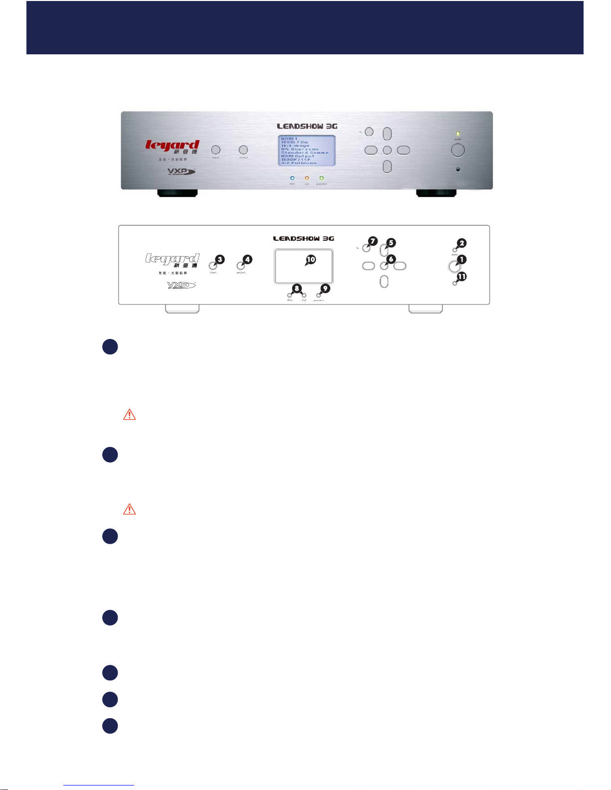
2.1 LEADSHOW 3G FRONT PANEL
POWER button
Press once to switch on; press once again to switch to standby.
The status is shown by the power indicator LED.
Caution: When Leadshow 3G is switched off, please wait for at least 10 seconds before
switching it on again.
POWER indicator LED
Green - Leadshow 3G is running
Red - Leadshow 3G is in standby mode
Caution: Never unplug the power plug when Leadshow 3G is running.
INPUT button
Press to cycle through the Leadshow 3G video input sources.
Input sources support HDMI; SDI; Component; RGBHV; S-Video; RGBs etc. Please refer to
Section 5.1.1: Input Select for details.
OUTPUT button
Press to cycle through the Leadshow 3G output ports:
HDMI 1; HDMI 2; Analog. See Section 5.3.1 to 5.3.3 for more information.
Navigation buttons
OK (setup) button
BACK button
2. FAMILIARIZING YOURSELF WITH LEADSHOW 3G
1
2
3
4
5
6
7
11
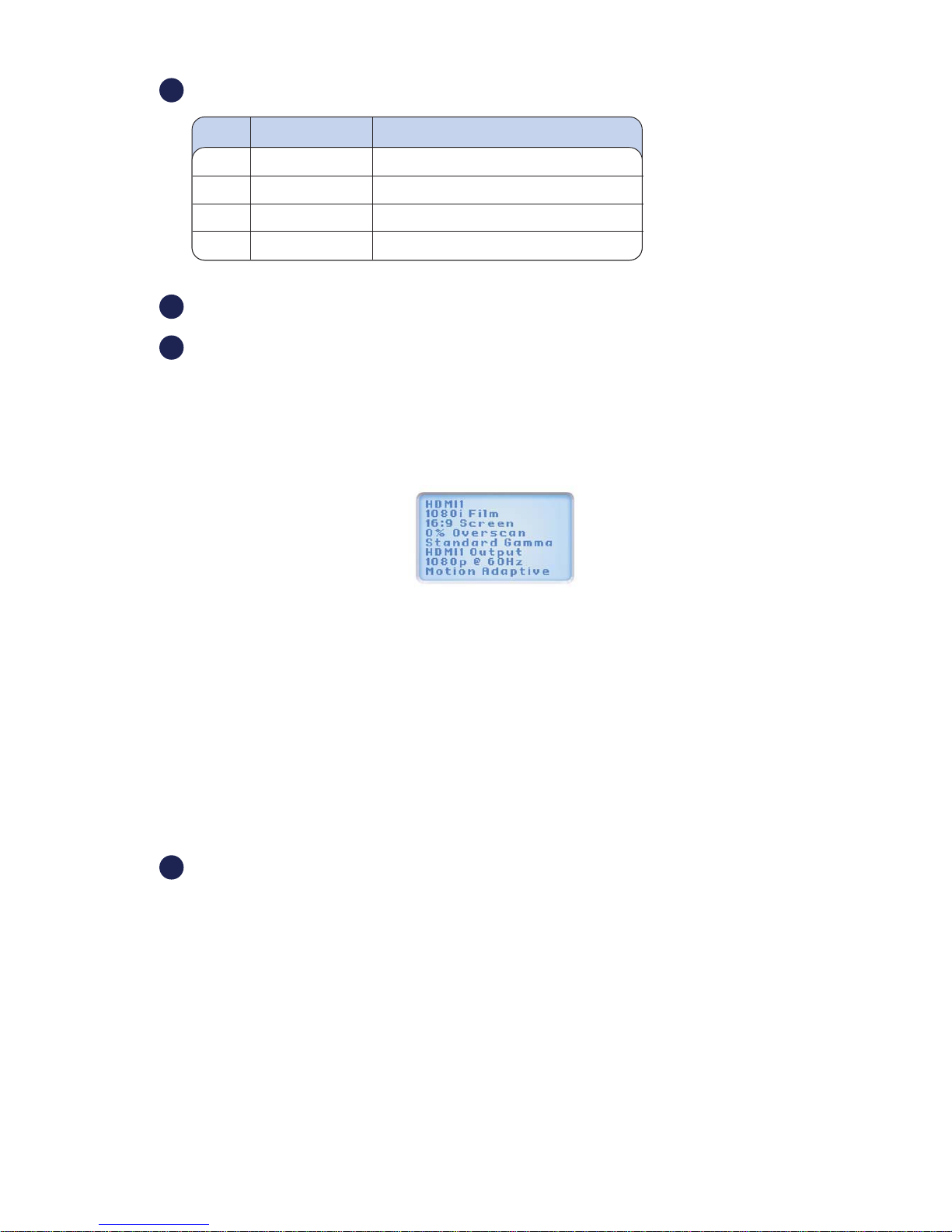
FILM & 2:2 PULLDOWN indicator LEDs
PASSTHRU indicator LED
LCD Display
The LCD display has 2 distinct modes see Section 6 for further details:
Status Display
By default, the LCD displays the current status of Leadshow 3G,
which includes the following information:
Input source format
Image aspect ratio
Overscan
Gamma type
Primary output port
Output resolution
Deinterlacing mode
Setup Display
When you are setting up Leadshow 3G , the LCD display shows the setup menu Typical operation
includes:
To enter menu set up mode, press [OK]
To highlight the previous or next item, press [UP] or [DOWN]
To increase or decrease value, press [LEFT] or [RIGHT]
To select an item or confirm setting, press [OK]
To exit and go up one level of the menu, press [BACK]
Infra Red (IR) input sensor
Film 2:2 Pulldown Mode
OFF OFF Video (Motion Adaptive Deinterlacing)
ON OFF Film (3:2 Pulldown)
ON ON Film (2:2 Pulldown)
OFF ON Not applicable
8
9
10
11
12
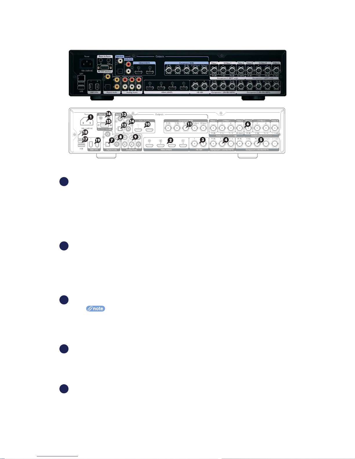
2.2 LEADSHOW 3G REAR PANEL
POWER
Power Supply Cable Entry
Use the cable supplied with your Leadshow 3G.
VIDEO INPUT TERMINALS
These allow you to connect your video sources to Leadshow 3G . Please refer to Section 3.3
for details.
Digital
HDMI 1; HDMI 2; HDMI 3; HDMI 4 (all HDCP and embedded digital audio)
Supported input resolutions:
480i, 576i, 480p, 576p, 720p, 1080i, 1080p,
640x480, 848x480, 852x480, 854x480, 856x480, 1024x576,
800x600, 1280x720, 1024x768, 1280x768, 1360x768, 1366x768, 1368x768,
1400x788, 1280x1024, 1400x1050, 1600x1200, 1920x1080
HD-SDI/SD-SDI 1; HD-SDI/SD-SDI 2
Leadshow 3G supports all SD-SDI and HD-SDI formats; 480i, 576i, 480p, 576p,
720p, 1080i, 1080p24sf
Analog
Component 1
Supports the following formats and resolutions:
Component Video YPbPr; 480i, 576i, 480p, 576p, 720p, 1080i
RGsB (RGB with sync on Green); 480p, 576p, 720p, 1080i, 800x600, 1024x768
Component 2
Supports the following formats and resolutions:
Component Video YPbPr; 480i, 576i, 480p, 576p, 720p, 1080i
RGBHV; 480p, 576p, 720p, 1080i, 800x600, 1024x768
RGBS (RGB with composite sync); 480p, 576p, 720p, 1080i, 800x600, 1024x768
RGsB (RGB with sync on Green); 480p, 576p, 720p, 1080i, 800x600, 1024x768
1
2
3
4
5
13

Component 3, Component 4
Support the following formats and resolutions:
Component Video YPbPr; 480i, 576i
RGBS (RGB with composite sync); 480i, 576i
2 x Composite (CVBS) Video and1xS-Video; 480i, 576i
AUDIO INPUT TERMINALS
Digital
Optical
Coaxial 1; Coaxial 2; Coaxial 3
Analog
Stereo Audio 1; Stereo Audio 2; Stereo Audio 3
VIDEO OUTPUT TERMINALS
Your display device(s) should be connected to these terminals. Leadshow 3G offers the following
connection configurations:
Digital
HDMI 1; HDMI 2 (both HDCP and embedded digital audio)
The HDMI (High Definition Multimedia Interface) provides the best quality video and audio output
from Leadshow 3G . If you are connecting to a display device that has a HDMI terminal, this is the
recommended option to use. This allows direct transmission of the video information from
Leadshow 3G to the display without any conversion from digital to analogue signals. Always use
high quality HDMI cables, especially for longer cable runs.
Supported output resolutions:
480p, 576p, 720p, 1080i, 640x480, 800x600, 852x480, 1024x576,1024x768, 1024x1024
ALiS, 1280x720, 1280x768, 1280x1024,1360x768, 1360x1024, 1366x768, 1368x768,
1400x788, 1400x1050,1920x1080, and customized resolutions up to 150MHz
Analog
BNC 1; BNC 2; BNC 3; BNC 4; BNC 5
Can be used either as:
RGBHV
RGBS (RGB with composite sync)
Supported RGBHV/RGBS output resolutions:
480p, 576p, 720p, 1080i, 640x480, 800x600, 852x480, 1024x576, 1024x768,
1024x1024 ALiS, 1280x720, 1280x768, 1280x1024, 1360x768, 1360x1024,
1366x768,1368x768, 1400x788, 1400x1050, 1920x1080, and customized
resolutions up to 165MHz
Component Video YPbPr; 480p, 576p, 720p, 1080i
AUDIO OUTPUT TERMINALS
Digital
Optical
Coaxial
Analog
Stereo Audio 1
7
8
9
10
11
12
13
14
14
6
COMPUTER/NETWORK CONNECTIVITY
These are optional/advanced connections
RS232 DB9 Male Serial connection
Allows Leadshow 3G to be integrated into and controlled by third party control systems.
Infrared In/Out for room-to-room remote control
USB2.0 port 1; USB2.0 port 2
Allows Leadshow 3G to be upgraded using a USB thumb disk and attached external drives for
media storage expansion.
RJ45 Ethernet connection
Allows Leadshow 3G to be connected to a computer network for playing
media files stored on shared folders or network servers, and network access of the internal hard
disk by networked PCs.
IEEE1394 Firewire connections
The Firewire connection is reserved for future use. If possible, activation will be carried out by a
future firmware update. Please check future firmware updates for information.
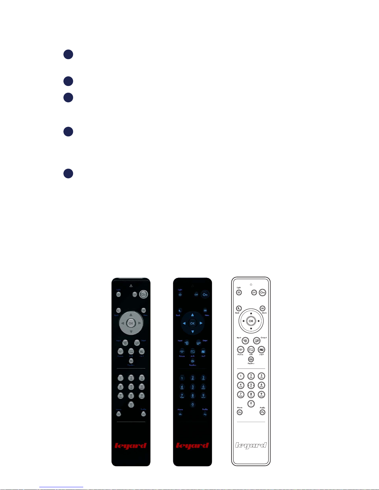
2.3 REMOTE CONTROL
one remote control for Leadshow 3G functions
2.3.1 MAIN LEADSHOW 3G REMOTE CONTROL
The main Leadshow 3G remote control is equipped with a motion sensor. Backlight automatically
turns on when the remote control is picked up.
18
19
15
16
17
15
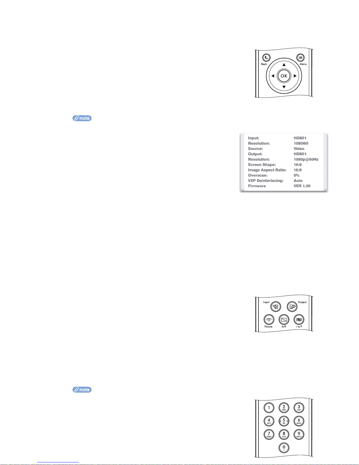
1 OSD group keys
Keys for OSD operations are:
Menu - enters and exits the on-screen display (OSD)
Arrow keys: Up, Down, Left,
Right - selects different items,
or adjusts values
OK - confirms the selected
item, or performs an action
Back - goes back to the previous
step or previous OSD page
When not in OSD menu, some keys have different functions:
OK - shows the Leadshow 3G status information:
Input:
Input source name, or user defined source name
Format, or resolution
Film, or Video source
Output:
Output port name, or user defined output name
Format, or resolution
Screen Shape
Image:
Aspect Ratio
Overscan
Deinterlace:
Faroudja mode if source is SD and DCDi is enabled (see Section 5.2.10)
VXP mode if source is HD
Firmware version
Down - selects the next input source
Up - selects the previous input source
Left - decreases image brightness by 1
Right - increases image brightness by 1
2 Quick Mini Menu Selection
When these keys are pressed, a mini menu selection list pops up on
screen. The following mini menu options are available:
Input - selects the input source
Output - selects the primary output port
Picture - adjusts Brightness, Contrast, Color Temp, Saturation, Hue
A/R - selects the image aspect ratio
itoP- selects the deinterlace method.
when input is HD, sets VXP deinterlace method
when input is SD and DCDi is enabled, sets Faroudja FLI2300 deinterlace method
Options are labeled by numbers and user can select options by pressing number keys
directly. See “Number Keys” below.
3 Number Keys
When in numeric entry box, pressing number keys enters the
number directly
16

Pressing Up arrow key will increase the numeric value by 1
Pressing Down arrow key will decrease the numeric value by 1
Pressing OK key confirms the numeric entry
Pressing the Back key will cancel the numeric value entered, and escape from the
numeric entry box
When in text entry box, pressing number keys enters the associated characters. For example,
pressing the 2 key will enter “A”. Pressing the 2 key again within a short period of time will
change “A” to “B”. Pausing between key presses will confirm the selection and the highlighted
area will move to the next character. The exact character sequences of pressing the number
keys are:
1 key: “1”, “-”, “(“, “)”, then “1” again
2 key: “A”, “B”, “C”, “2”, “a”, “b”, “c”, then “A” again
3 key to 9 key: similar to 2 key but taking you through the rest of the alphabet
0 key: “0”, “ “, then “0” again
Pressing the Up arrow key will change the character to the previous letter
Pressing the Down arrow key will change the character to the next letter
Pressing OK key confirms the text entry
Pressing the Back key will clear the current character entered; the highlight will move left
to the previous character position
When in Quick Mini Menu Selection, pressing a number key selects one of the options directly
(no need to use arrow key followed by OK).
When not in OSD mode, pressing number keys will perform the following operations:
[1] : Input Select HDMI1
[2] : Input Select HDMI2
[3] : Input Select HDMI3
[4] : Input Select SDI1
[5] : Input Select Component1
[6] : Input Select Component2
[7] : Image Aspect Ratio 4:3
[8] : Image Aspect Ratio 16:9
[9] : Image Aspect Ratio NLS
[0] : Image Gamma Adjust OSD Setup
4 Other keys
On: Power on
Off: Power off
Light:
Turns on Leadshow 3G Front Panel LCD light for a short time
When in OSD menu, toggles Hide/Show of the whole OSD (note that the OSD
menu will still exit after the time-out period)
Profile: Video Profile recall
Macro: Macro recall
#
Passthru: Toggles the current input source between passthru mode and normal
processing mode
# Macro definition and recall are available only in firmware version 2.00 or later
17

3.1 COMPATIBLE EQUIPMENT
In simple terms, Leadshow 3G serves as a video processor which enhances video signals from
source devices and then delivers the enhanced video signal to the display devices.
Leadshow 3G is compatible with:
Any source device capable of outputting:
Composite Video
S-Video
RGsB (RGB with sync on Green)
RGBS (RGB with Composite Sync)
Component (YPbPr)
VGA (HD15 RGBHV)
Digital DVI
SDI (Serial Digital Interface)
HDMI (High Definition Multimedia Interface)
HD-SDI (High Definition Serial Digital Interface)
Any analog or digital display device capable of accepting input in the form of:
Analog RGBHV
Analog RGBS (RGB with composite sync)
Analog Component (YPbPr)
Digital HDMI
Digital DVI (With suitable adaptor or HDMI>DVI cable)
3.2 MAINS
Caution: Connect Leadshow 3G to a power point using the mains cable provided.
3.3 VIDEO INPUTS
Leadshow 3G includes a comprehensive set of input terminals to allow you to connect a wide range
of video sources. Please refer to Section 2.2 for the supported input resolutions of each input port.
For the best results you should:
use the highest quality output that your video source provides
use high quality cables for all connections
When deciding on which output to use from your device, use the following list as a guideline
(with highest quality being first):
High Definition
1 HD-SDI - A direct digital broadcast-quality connection.
2 HDMI - A direct digital connection available on many high definition consumer devices.
3 Component (YPbPr) - An analog connection capable of carrying high definition signals.
Standard Definition
1 SD-SDI or HDMI - (a direct digital connection from a compatible set top box or DVD
player).
2 RGB (RGBHV/RGsB/RGBS) - often available from set top boxes, DVD players, games
consoles etc.
3 Component (YPbPr) - typically available on mid-range to high-end DVD players and
some games consoles.
4 S-Video - a general purpose connection found on many devices. Sometimes incorrectly
3. HARDWARE INSTALLATION
18

referred to as SVHS.
5 Composite - the most common and lowest performing video connection.
TIPS: It is recommended that you try to bypass any internal processing in your source by
choosing the output signal that matches the media type. For example, choose the interlaced
output from your DVD player or standard definition set-top-box instead of the progressive (e.g.
480i instead of 480p). This leaves the conversion from interlaced video to progressive video to
be performed by Leadshow 3G , which has sophisticated processing dedicated to this task.
3.4 VIDEO OUTPUTS
For maximum performance you should use the digital connection where possible.
The reason for this is that the display of a digital device (for example a plasma panel, TFT
monitor or LCD/LCOS/DLP projector) is built up of a grid of a fixed number of elements or pixels,
which are all directly and individually controlled by the internal digital electronics of the display.
Using the HDMI interface of the display allows these individual pixels to be directly controlled by
Leadshow 3G , bypassing the internal picture processing electronics of the display device, and
thereby producing more detailed and accurate images.
When deciding on which output to use from Leadshow 3G , use the following list as a guideline
(highest quality first):
1 HDMI (a direct digital connection from Leadshow 3G to the display device).
2 RGBHV/RGBS.
3 Component video.
Some digital displays may not accept their native resolution via HDMI. In these cases
better results may be possible using the display’s VGA or computer RGBHV input. This may
allow 1:1 pixel mapping to be achieved (See Section 4.6.1).
3.5 PRODUCT REGISTRATION
To enjoy the 12-month warranty for your Leadshow 3G , you must register online at:
http://www.leyard.com
This will only take a couple of minutes. You will need your serial number so please make a note
of it prior to registering your Leadshow 3G.
Once registered, you will be entitled to view technical information, online product support and, of
course software updates for your Leadshow 3G.
19

4.1 CONFIGURE YOUR VIDEO SOURCE
Even if your standard definition video source has the option to output progressive video
(denoted by a number and then the letter ‘p’, for example 480p), for maximum results, it is
recommended to disable such an option and select interlaced video mode instead (denoted
by a number and then the letter ‘i’, for example 480i).
Leadshow 3G features state-of-the-art technology specifically designed to convert interlaced video
into progressive video. This will usually deliver higher performance than the converter built into
your source device.
Similarly, your high definition source may have an option to scale the incoming signal to a fixed
output resolution. Again, it is advisable to turn this feature off as the sophisticated scaling
algorithms in Leadshow 3G will produce far cleaner results.
4.2 SWITCH ON LEADSHOW 3G
Press the POWER button on the front panel. The Power LED should show green and the LCD
display illuminates. Note that you will need to wait for approximately 5 seconds for Leadshow 3G
to initialize and for video to display.
If you do not see video as expected, refer to Section 8: Troubleshooting.
The default video output of Leadshow 3G is 720p. Most high definition displays can lock to
720p which should then enable you to use the OSD to correctly configure Leadshow 3G.
4.3 SELECT INPUT VIDEO SOURCE
Using the remote control
Press the Menu remote control key to enter the OSD menu, then select Input Select in the Input
sub-menu. Select the type of input port via which your input device has been connected and
press OK to confirm.
OR
Press the Input remote control key and a mini menu selection list pops up. Select the type of
input port via which your input device has been connected and press OK to confirm.
OR
Using the front panel control
1 Press OK button to start Main Menu
2 Select Input and choose Input Select
3 Choose input port via which your input device is connected
4 Press OK button to confirm
OR
Press the INPUT button to cycle through the various input terminals and stop at the one through
which your input device is connected.
4.4 SELECT PRIMARY OUTPUT PORT
Using the remote control
Press the Menu remote control key to enter the OSD menu, then select Output Select in the
Output sub-menu. Select the output terminal via which your display device has been connected
and press OK to confirm.
4. BASIC SETUP
20

OR
Press the Output remote control key and a mini menu selection list pops up. Select the output
terminal via which your display device has been connected and press OK to confirm.
OR
Using the front panel control
1 Press OK button to start Main Menu
2 Select Output and choose Output Select
3 Choose output terminal to which your display device is connected
4 Press OK button to confirm
OR
Press the Output remote control key to cycle through the various output terminals and stop at
the one through which your display device is connected.
4.5 SET OUTPUT FORMAT/RESOLUTION
Using the remote control
Press the Menu remote control key to enter the OSD menu, then select Resolution in the Output
sub-menu. Choose Standard Format or Fixed Resolution of the display device being connected in
and press the action button to confirm.
OR
Using the front panel control
1 Press OK button to start Main Menu
2 Select Output and choose Resolution
3 Choose output resolution which your display device requires
4 Press OK button to confirm
4.6 BASIC SETUP TIPS FOR DIGITAL DISPLAYS/PROJECTORS
4.6.1 PIXEL PERFECT
Every pixel-based digital display has a native resolution*, so any video source displayed needs
to be scaled from its original resolution (size) to the native resolution of the display for optimum
results. If the Leadshow 3G output resolution is mapped to the display in 1:1 mode, or pixel perfect
mode, this ensures all video processing and scaling is done by Leadshow 3G . This is very important
because:
It ensures that the display’s internal scaler is bypassed, allowing you to benefit from the
image processing power of Leadshow 3G
It avoids double scaling and processing done to the video source, which would
introduce video artifacts, especially during smooth motion e.g. camera pans
* A display’s native resolution is expressed as number of pixels wide by number of pixels high. For example many DLP projectors are 1280
x 720, so for optimum results all video should be scaled to that number of pixels. Think of this as addressing the exact number of active
pixels; once this has been done as detailed below you have achieved 1:1 mapping, or pixel perfect mode.
To make sure Leadshow 3G’s output is pixel perfect, please make use of the Leadshow 3G internal
video test patterns to confirm 1:1 pixel mapping has been achieved. See the examples overleaf:
21
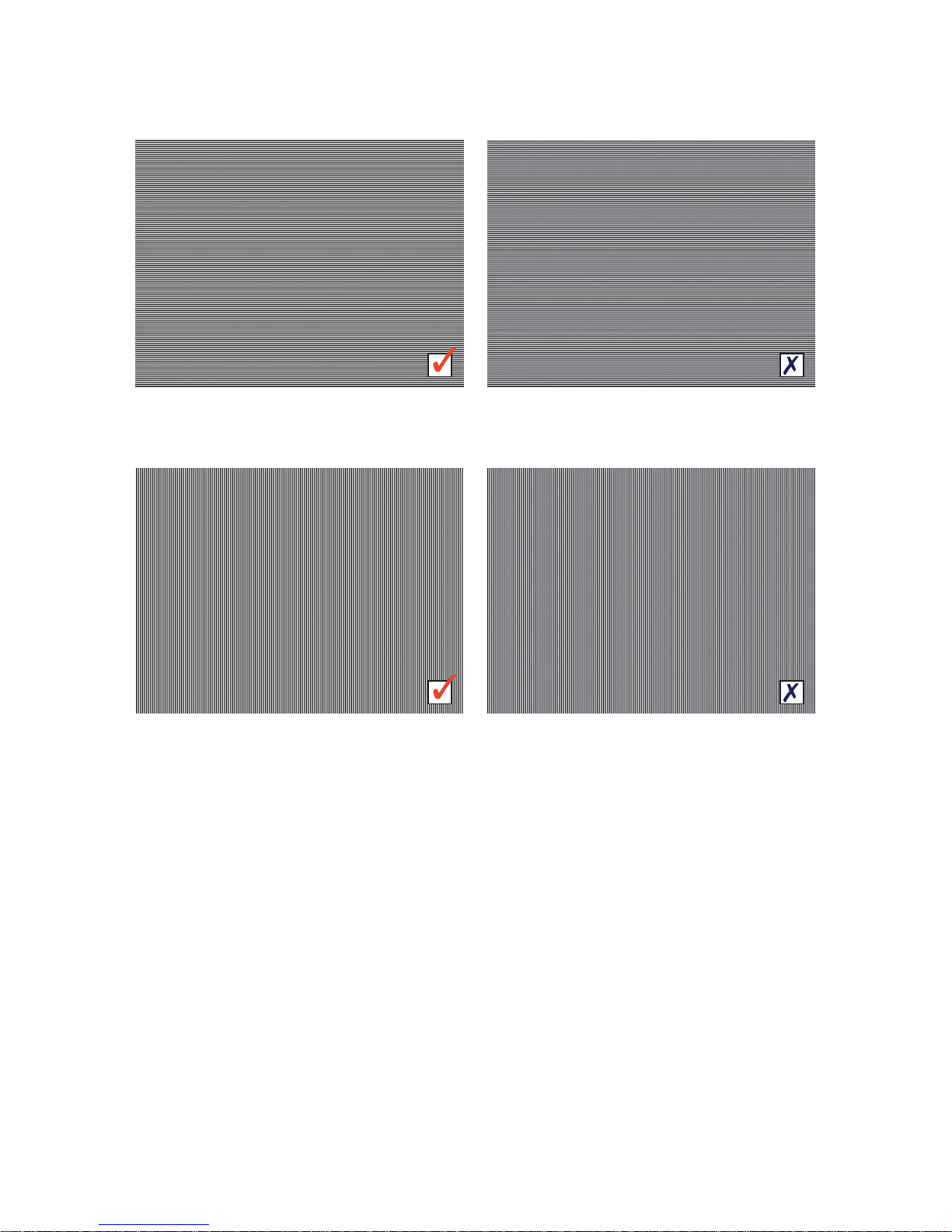
Video Test Pattern: Horizontal Line 50
Pixel Perfect
Video Test Pattern: Horizontal Line 50
Not Pixel Perfect
Video Test Pattern: Vertical Line 50
Pixel Perfect
Video Test Pattern: Vertical Line 50
Not Pixel Perfect
22
If viewing these images on a computer screen please use the zoom function in
Adobe Acrobat Reader to properly view the differences between these images
TIP: If you think that you have set Leadshow 3G to your display's native resolution, yet the images above still don't appear
correctly, try using the 'Horizontal Line 50' pattern and making small adjustments to your display's V-Size. There may be a
setting where it 'snaps' into focus. Then try 'Vertical Line 50' and adjust your display's H-Size. Once you think you have the
patterns in focus, select the 'Overscan' test pattern and use your display's H- and V-Position controls to center the image.

4.6.2 OUTPUT 50HZ OR 60HZ AUTOMATICALLY
If your display supports 50Hz input and can produce real 50Hz refresh rate video image*, it is
better to configure Leadshow 3G to output 50Hz resolution when source video is 50Hz (i.e. PAL
signal); and output 60Hz resolution when the source video is 60Hz (i.e. NTSC signal). This is
because the output video will be perfectly smooth if the refresh rate of video image displayed is
the same as that of the video source. Otherwise, you will see slight jerkiness of subject
movement, especially when there are camera pans.
* Some displays that support 50Hz input will convert the 50Hz video back to the display’s native 60Hz (the majority of pixel-based
displays have a native 60Hz vertical refresh rate) and produce a 60Hz refresh rate video image. You can verify this if you have
configured Leadshow 3G to output the same refresh rate as the input; if with a 50Hz source you see jerkiness in the image, your
display’s internal scaler may be performing a frame rate conversion to 60Hz
To configure Leadshow 3G to output 50Hz resolution when input refresh rate is 50Hz, and output
60Hz resolution when input refresh rate is 60Hz, follow the steps below:
Press the Menu remote control key to enter the OSD (On Screen Display) menu
Select System then DynamicVP
TM
(if you can’t see the DynamicVPTMoption, select the
Advanced Option under System sub-menu and turn Advanced Option ON first)
Turn the DynamicVP Mode ON
In the first line of rules under When Input, select 50Hz
In the first line of rules under Action/Resolution, select Fixed Resolution
In the dropdown list of resolutions, select your display’s native resolution; then in the
dropdown list of refresh rates, select 50Hz
In the second line of rules under When Input, select 60Hz
In the second line of rules under Action/Resolution, select Fixed Resolution
In the dropdown list of resolutions, select your display’s native resolution; then in the
dropdown list of refresh rates, select 60Hz
Press the Menu remote control key to exit the OSD menu
4.6.3 BASIC CALIBRATIONS
4.6.3.1 CALIBRATE THE VIDEO LEVEL AND COLOR BALANCE OF YOUR
DISPLAY/PROJECTOR
Leadshow 3G has been designed and built to output broadcast standard video. You can even use
Leadshow 3G as a reference video signal generator. You should therefore make use of the internal
video test patterns to calibrate the video output level and color balance of your display.
Step 1: Reset Leadshow 3G’s video settings to the default values, which include:
Contrast, Brightness (default = 0)
Red, Green, Blue Offsets and Gains (default = 0)
Gamma correction (default type Standard, and value = 0)
Step 2: Select a correct output video level from Leadshow 3G’s HDMI output port:
Press the Menu remote control key to enter the OSD (On Screen Display) menu
Select Output then Output Port Configuration. You should see output configuration
options of HDMI output ports (If not, select the Advanced Option under System sub-menu
and turn Advanced Option ON first)
If your display is expecting video from a video source with HDMI output, configure
Leadshow 3G’s HDMI output level as HDMI Standard
If your display is expecting video from a normal consumer AV product, configure
Leadshow 3G’s HDMI output level as Video Level (16-235)
If your display is expecting video from a PC, configure Leadshow 3G’s HDMI output level as
PC Level (0-255)
23

If you are not sure which video level is correct, leave it at the default setting. Or, if the
picture is excessively dark or very washed out, try changing the HDMI output level to see
which one looks the best
Step 3: Calibrate the black level (brightness) of your display:
Show the internal video test pattern Black 1-3% (under the OSD menu System and
Video Test Patterns)
Turn the brightness setting of your display down excessively so that the whole
screen is black
Turn the brightness up until you can barely see the difference of the 1%, 2%,
and 3% bars
Step 4: Calibrate the white level (contrast or peak white level) of your display:
Show the internal video test pattern White 97-99%
Turn the contrast setting of your display up excessively so that you see the whole
image as white
Turn the contrast down until you can barely see the difference between the 97%,
98%, and 99% bars
Step 5: Calibrate the color balance of your display:
Show the internal video test pattern Cross Gray Steps, and pay attention to the
black bar and white (100 IRE) bar
Adjust Red, Green, and/or Blue offset/bias settings of your display to fine tune
the color of the black bar if it doesn’t look a neutral black*
Adjust Red, Green, and/or Blue gain settings of your display to fine tune the
color of white bar if it doesn’t look a neutral white*
*Aim to lower the color you see as dominant rather than increasing the other two
Step 6: Repeat step 3 to step 5 until the brightness and contrast settings don’t need changing,
and R/G/B offset and R/G/B gain settings of your projector are satisfactory.
Step 7: If the color balance of your projector still isn’t good enough after the R/G/B offsets and
gains have been tuned, you need to use Leadshow 3G’s Advanced Gamma Correction *
function to adjust further.
Press Menu remote control key to enter OSD (On Screen Display) menu
Select the Advanced Option under System sub-menu and turn Advanced Option ON
Select Image, then Gamma Correction, then R/G/B and press the action button
You can adjust the color balance of mid-tone by selecting
Standard Gamma Curve
You can adjust the color balance of low-mid-tone by selecting
Low IRE Gamma Curve
You can adjust the color balance of hi-mid-tone by selecting
High IRE Gamma Curve
After Gamma Correction, remember to store this gamma setting in a Gamma Profile and
associate it to the primary output port. When switching primary output port, you should
load this Gamma Profile in order to keep this color balance with your projector
* Advanced Gamma Correction function is available only in firmware version 2.00 or later
If you have two digital displays connected to Leadshow 3G’s HDMI output ports, you have to
calibrate each of them according to the steps above. Remember to:
Reset Leadshow 3G’s video settings before your calibration
Associate Gamma Profiles to each HDMI output if you have used Advanced Gamma
Correction to fine tune the color balance of your displays
24

4.6.3.2 CALIBRATE THE VIDEO LEVEL AND COLOR BALANCE OF YOUR VIDEO
SOURCES
Once you have calibrated your display for correct video output levels and color balance, you
don’t have to calibrate your video sources if they also have correct video level and color balance.
But in practice, however, most of the video sources will still have some form of problem with
video levels or color balance and we have to calibrate them one by one for perfect results.
To calibrate video sources, we ideally need test patterns originating from the video source.
This is straightforward using readily available specialist calibration DVDs. Many HDTV stations
also carry test material at certain times of the day. In the absence of any specific test material it
is quite difficult to calibrate, as you can only make the picture look how you expect it to be.
This may not be correct, so check several discs to gain a good balance. Please follow the steps
below for each video source connected to Leadshow 3G:
Step 1: Reset Leadshow 3G’s video settings to the default values:
Contrast, Brightness (default = 0)
Red, Green, Blue Offsets and Gains (default = 0)
Gamma correction (default type Standard, and value = 0)
Step 2: For sources connected to Leadshow 3G’s HDMI input ports, select the correct input video:
Press Menu remote control key to enter OSD (On Screen Display) menu
Select Input, then Input Port Configuration, then press the action
button. (If you can’t find the action button, select the Advanced
Option under System sub-menu and turn Advanced Option ON first).
If your source device is equipped with HDMI output, configure Leadshow 3G’s HDMI input
level as HDMI Standard
If your source device is a normal consumer AV product, configure Leadshow 3G’s HDMI
output level as Video Level (16-235)
If your source device is a PC, configure Leadshow 3G’s HDMI output level as PC
Level (0-255)
If you are not sure what video level is correct, leave it set at Standard. Or if the picture is
excessively dark or very washed out, try changing the HDMI input level to see if which
one is the best
Step 3: Calibrate the black level (brightness) of your video source:
Find a video test pattern for adjusting black level, e.g. the Black Bar pattern from AVIA
Turn the brightness setting of Leadshow 3G down excessively so that you see the whole
image as black
Turn the brightness up until you can barely see the difference of the black background
and the slightly brighter black bar (AVIA test)
Step 4: Calibrating the white level (contrast or peak white level) of your video source:
Find a video test pattern for adjusting white level, e.g. the Needle Pulse from AVIA
Turn the
contrast setting of Leadshow 3G up excessively so that you see the whole
image as white
Turn the contrast down until you can barely see the difference of the white background
and the slightly darker white bar
Step 5: Calibrating the color balance of your video source:
Find a video test pattern with 0 to 100 IRE (stair step patterns are ideal) and pay
attention to the black bar and white (100 IRE) bar
Adjust Red, Green, and/or Blue Offset
settings of Leadshow 3G to fine tune the color of
black bar if it doesn’t look a neutral black
Adjust Red, Green, and/or Blue Gain settings of Leadshow 3G to fine tune the color of white
bar if it doesn’t look a neutral white
25
 Loading...