

Page 1
Hybrid
2008 Model
© 2007 Toyota Motor Corporation
All rights reserved. This document may not be
altered without the written permission of Toyota Motor Corporation.
08LS 600h L ERG REV – (01/10/08)
Page 2
Foreword
In May 2007, Lexus released the Lexus LS 600h L gasoline-electric
hybrid vehicle in North America. Except where noted in this guide,
basic vehicle systems and features for the LS 600h L are the same as
those on the conventional, non-hybrid, Lexus LS 460 L. To educate
and assist emergency responders in the safe handling of the LS 600h L
hybrid technology, Lexus published this LS 600h L Emergency
Response Guide.
High voltage electricity powers the electric motor, generator, A/C
compressor, and power control unit (inverter/converter). Other
automotive electrical devices such as the horn, radio, and gauges are
powered from a separate 12 Volt auxiliary battery. Numerous
safeguards have been designed into the LS 600h L to help ensure the
high voltage, approximately 288 Volt, Nickel Metal Hydride (NiMH)
Hybrid Vehicle (HV) battery pack is kept safe and secure in an accident.
The LS 600h L utilizes the following electrical systems:
• Maximum 650 Volts AC
• Nominal 288 Volts DC
• Maximum 46 Volts AC / DC
• Nominal 12 Volts DC
LS 600h L Features:
• A mechanical all-wheel drive hybrid powertrain.
• A boost converter in the power control unit that boosts to 650 Volts
the available voltage to the electric motor.
• A high voltage Hybrid Vehicle (HV) battery pack rated at 288 Volts.
• A high voltage motor driven Air Conditioning (A/C) compressor
rated at 288 Volts.
• An Electric Power Steering (EPS) assist motor rated at 46 Volts.
• Active stabilizer suspension system motors rated at 46 Volts.
• A body electrical system rated at 12 Volts, negative chassis ground.
• Supplemental Restraint System (SRS) - dual stage frontal airbags,
front knee airbags, front seat and optional rear seat side airbags,
side curtain airbags, front and rear seat belt pretensioners, and when
equipped with an optional rear seat Ottoman, a passenger side rear
seat cushion airbag.
High voltage electrical safety is an important factor in the emergency
handling of the LS 600h L Lexus Hybrid Drive. It is important to
recognize and understand the disabling procedures and warnings
throughout the guide.
Additional topics in the guide include:
• Lexus LS 600h L identification.
•
Major Lexus Hybrid Drive component locations and descriptions.
•
Extrication, fire, recovery, and additional emergency response
information.
•
Roadside assistance information.
2008 Model Year LS 600h L
This guide is intended to assist emergency responders in the safe
handling of a Lexus LS 600h L hybrid vehicle during an incident.
NOTE:
Emergency Response Guides for Lexus hybrid vehicles may be viewed at
http://techinfo.lexus.com.
-i-
Page 3

Table of Contents Page
About the LS 600h L 1
LS 600h L Identification 2
Lexus Hybrid Drive Component Locations & Descriptions 5
Smart Access System & Push Button Start 8
Lexus Hybrid Drive Operation 10
Hybrid Vehicle (HV) Battery Pack 11
46 Volt System 12
Low Voltage Battery 13
High Voltage Safety 14
SRS Airbags & Seat Belt Pretensioners 15
Emergency Response 17
Extrication 17
Fire 24
Overhaul 25
Recovering/Recycling of NiMH HV Battery Pack 25
Spills 26
First Aid 26
Submersion 27
Roadside Assistance 28
-ii-
Page 4
About the LS 600h L
The LS 600h L sedan joins the RX 400h and GS 450h as a hybrid
model for Lexus. Lexus Hybrid Drive means that the vehicle contains
a gasoline engine and an electric motor for power. The two hybrid
power sources are stored on board the vehicle:
1. Gasoline stored in the fuel tank for the gasoline engine.
2. Electricity stored in a high voltage Hybrid Vehicle (HV) battery pack
for the electric motor.
The result of combining these two power sources is improved fuel
economy and reduced emissions. The gasoline engine also powers an
electric generator to recharge the battery pack; unlike a pure all electric
vehicle, the LS 600h L never needs to be recharged from an external
electric power source.
Depending on the driving conditions one or both sources are used to
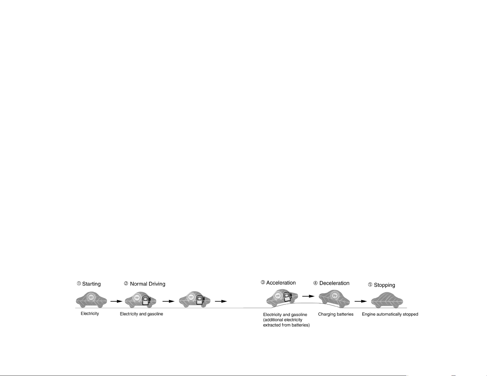
power the vehicle. The following illustration demonstrates how the LS
600h L operates in various driving modes.
During light acceleration at low speeds, the vehicle is powered by
the electric motor. The gasoline engine is shut off.
During normal driving, the vehicle is powered mainly by the
gasoline engine. The gasoline engine also powers the generator to
recharge the battery pack.
During full acceleration, such as climbing a hill, both the gasoline
engine and the electric motor power the vehicle.
During deceleration, such as when braking, the vehicle regenerates
the kinetic energy from the wheels to produce electricity that
recharges the battery pack.
While the vehicle is stopped, the gasoline engine and electric motor
are off, however the vehicle remains on and operational.
-1-
Page 5
LS 600h L Identification
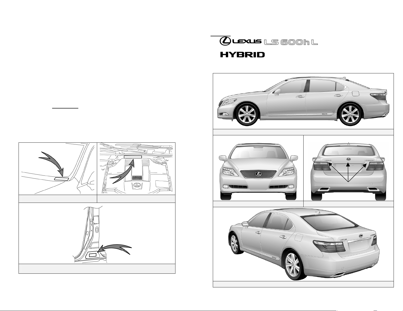
In appearance, the 2008 model year LS 600h L is nearly identical to the
conventional, non-hybrid Lexus LS 460 L. The LS 600h L is a 4-door
sedan and the suffix “L” indicates a long wheelbase. Exterior, interior,
and engine compartment illustrations are provided to assist in
identification.
The alphanumeric 17 character Vehicle Identification Number (VIN) is
provided in the front windshield cowl, driver door pillar, and engine
compartment.
Example VIN:JTHDU46F840020208
An LS 600h L is identified by the first 6 alphanumeric characters
JTHDU4.
Exterior
logos on the rear trunk.
logos on the rear door moldings.
Gasoline fuel filler door located on the driver side rear quarter panel.
Exterior Driver Side View
Driver Side Windshield Engine Compartment Cowl
Exterior Front View Exterior Rear View
Base of Driver Side B Pillar
-2-
Exterior Rear and Driver Side View
Page 6
LS 600h L Identification (Continued)
Interior
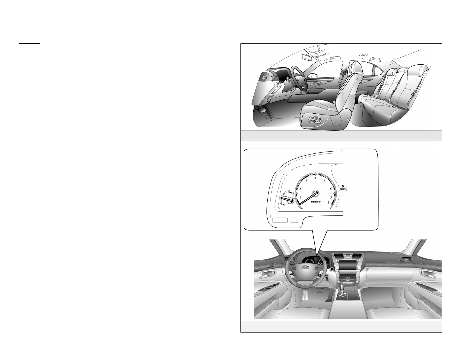
The instrument cluster (speedometer, fuel gauge, warning lights) located
in the dash behind the steering wheel, is different than the one on the
conventional, non-hybrid LS 460 L.
The hybrid system indicator (power meter) is located next to the
tachometer.
NOTE:
If the vehicle is shut off, the instrument cluster gauges will be “blacked
out”, not illuminated.
Interior View
-3-
Instrument Cluster View
Page 7
LS 600h L Identification (Continued)
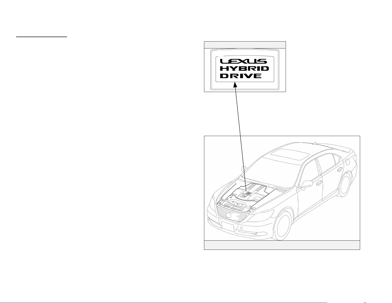
Engine Compartment
5.0-liter aluminum alloy gasoline engine.
Logo on the plastic engine cover.
Logo on Cover
Engine Compartment View
-4-
Page 8
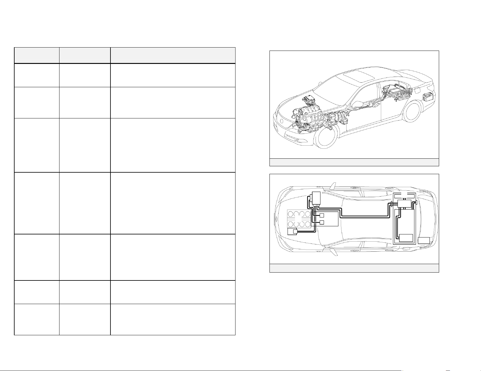
Lexus Hybrid Drive Component Locations &
Descriptions
Component Location Description
12 Volt
Auxiliary
Battery
Hybrid
Vehicle (HV)
Battery Pack
Power
Cables
Power
Control Unit
Gasoline
Engine
Electric
Generator
Electric
Motor
Trunk Driver Side A lead-acid battery that supplies power to
the low voltage devices.
Trunk Area,
Mounted to Cross
Member and
behind Rear Seat
Undercarriage
and Engine
Compartment
Engine
Compartment
Engine
Compartment
Transmission 3-phase high voltage AC generator that is
Transmission 3-phase high voltage AC permanent magnet
288 Volt Nickel Metal Hydride (NiMH)
battery pack consisting of 20 low voltage
(14.4 Volt) modules connected in series.
Orange colored power cables carry high
voltage Direct Current (DC) between the
HV battery pack, power control unit, and
A/C compressor. These cables also carry 3phase Alternating Current (AC) between the
power control unit, electric motor, and
generator.
Boosts and inverts the high voltage
electricity from the HV battery pack to 3phase AC electricity that drives the electric
motor. The power control unit also
converts AC electricity from the electric
generator and electric motor (regenerative
braking) to DC that recharges the HV
battery pack.
Provides two functions:
1) Powers vehicle.
2) Powers generator to recharge the HV
battery pack.
The engine is started and stopped under
control of the vehicle computer.
contained in the transmission and recharges
the HV battery pack.
electric motor contained in the transmission
and drives the four wheels through the
transfer case and propeller shafts.
Lexus Hybrid Drive Components
Components (Top View) and High Voltage Power Cables
-5-
Page 9
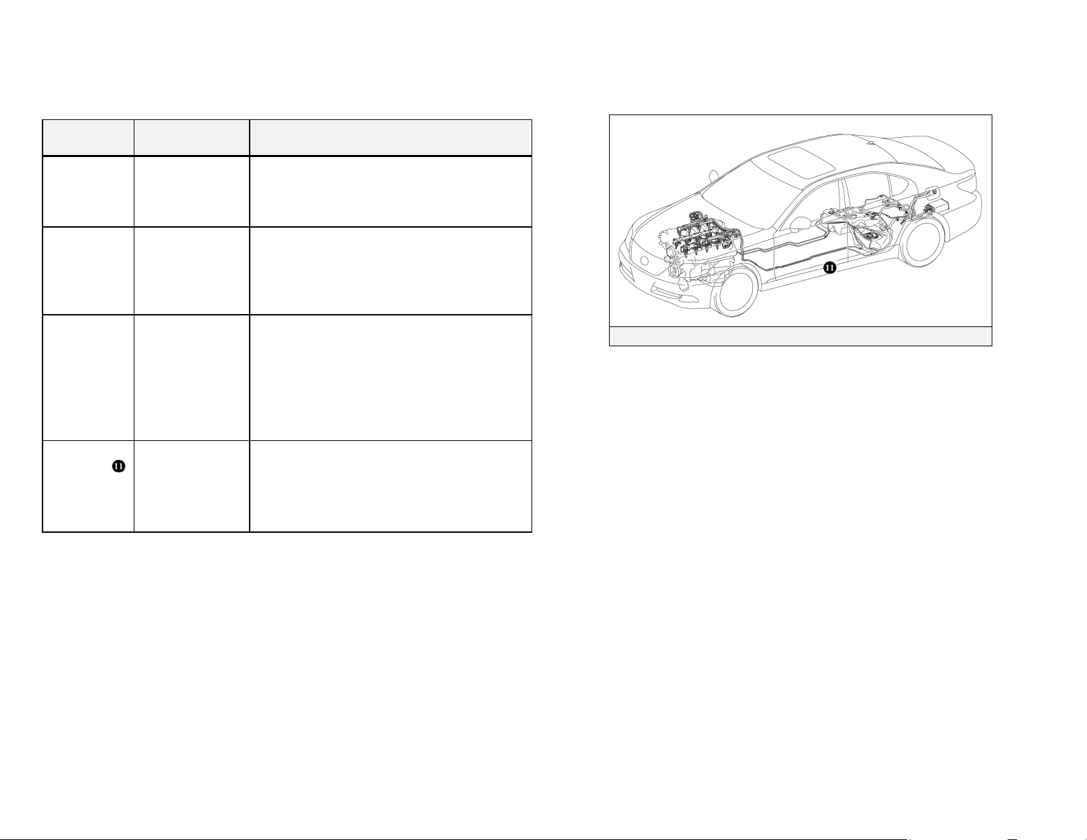
Lexus Hybrid Drive Component Locations &
Descriptions (Continued)
Component Location Description
A/C
Compressor
(with
Inverter)
DC-DC
Converter
for 12 Volt
Auxiliary
Battery
DC-DC
Converter
for EPS and
Active
Stabilizer
Suspension
System
Fuel Tank and
Fuel Lines
Engine
Compartment
Inside HV Battery
Pack in Trunk
On HV Battery
Pack
Undercarriage,
Driver Side and
Center
3-phase high voltage AC electrically driven
motor compressor.
Converts 288 Volts from the HV battery
pack to 12 Volts for low voltage vehicle
power.
Converts 288 Volts from the HV battery
pack to 46 Volts for EPS and active
stabilizer suspension system power. Dull
yellow colored sheathing identifies 46 Volt
wires that are routed under the vehicle body
to power the EPS and the active stabilizer
suspension system.
The fuel tank provides gasoline via fuel
lines to the engine. The source fuel lines
are routed under the vehicle along the
center tunnel and the return line is routed
along the driver side under the floor pan.
Fuel Tank and Fuel Lines
-6-
Page 10
Lexus Hybrid Drive Component Locations &
Descriptions (Continued)
Key Specifications:
Gasoline Engine: 390 hp (290 kW), 5.0-liter Aluminum Alloy Engine
Electric Motor: 221 hp (165 kW), Permanent Magnet Motor
Transmission: Automatic Only (electrically controlled
continuously
variable transmission)
HV Battery: 288 Volt Sealed NiMH
Curb Weight: 5,049 lbs / 2,290 kg
Fuel Tank: 22.1 gals / 84 liters
Fuel Economy
Ratings: 20/22 (City/Hwy) miles/gal
11.3/8.0 (City/Hwy) liters/100 km
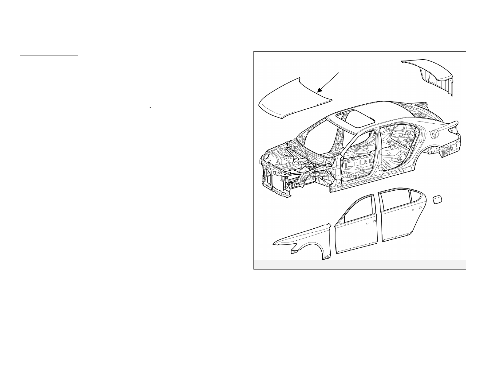
Frame Material: Steel Unibody
Body Material: Steel Panels except for Aluminum Hood
Battery
Aluminum
-7-
Steel Unibody
Page 11
Smart Access System & Push Button Start
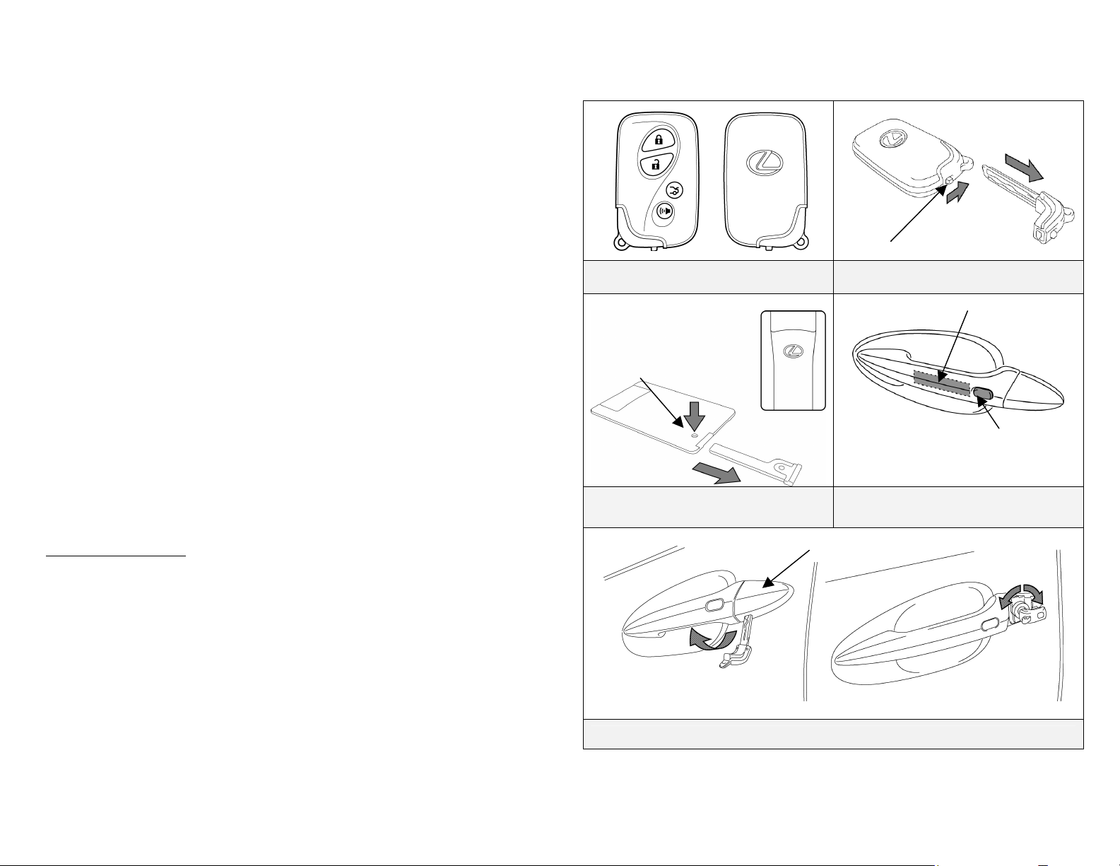
The LS 600h L smart access system consists of a smart key
transceiver that communicates bi-directionally enabling the vehicle to
recognize the smart key in close proximity to the vehicle. Once
recognized, the smart key will allow the user to lock and unlock the
doors without pushing smart key buttons, and start the vehicle without
inserting it into an ignition switch.
Smart key features:
•
Passive (remote) function to lock/unlock the doors and start the
vehicle.
•
Wireless transmitter buttons to lock/unlock the doors and unlock
the trunk.
• Hidden metal cut key to lock/unlock the doors and trunk from the
exterior.
The LS 600h L is equipped with two types of smart keys:
• Smart key (fob)
• Card smart key
The card smart key is designed to be stored in a wallet and has all the
same functions as the smart key (fob), except push buttons.
Door (Lock/Unlock)
Three methods are available to lock/unlock the doors.
1. Pushing wireless smart key lock/unlock buttons.
2. Touching the sensor on the backside of any exterior door handle, with
the smart key in close proximity to the vehicle, unlocks the doors.
Pushing the lock button on any exterior door handle locks the doors.
3. Removing the driver door handle cover, inserting the hidden metal cut
key in the driver door lock and turning the key clockwise once unlocks
the driver door, twice unlocks all doors. To lock all doors turn the key
counter-clockwise once. Only the driver door contains an exterior door
lock for the metal cut key.
Smart Key (Fob)
Release Button
Card Smart Key and Hidden Metal Cut
Key for Door Lock
Remove the Cover
Hidden Front Driver Door Lock
Release Button
Hidden Metal Cut Key for Door Lock
(Smart Key)
Unlock Touch
Sensor
Driver Door Unlock Touch Sensor and
Lock Button
Cover
Use the Hidden Metal Cut Key
Lock
-8-
Page 12
Smart Access System & Push Button Start (Continued)
Vehicle Starting/Stopping
The smart key has replaced the conventional metal cut key, and the power
button with an integral status indicator light has replaced the ignition switch.
The smart key only needs to be in proximity to the vehicle to allow the
system to function.
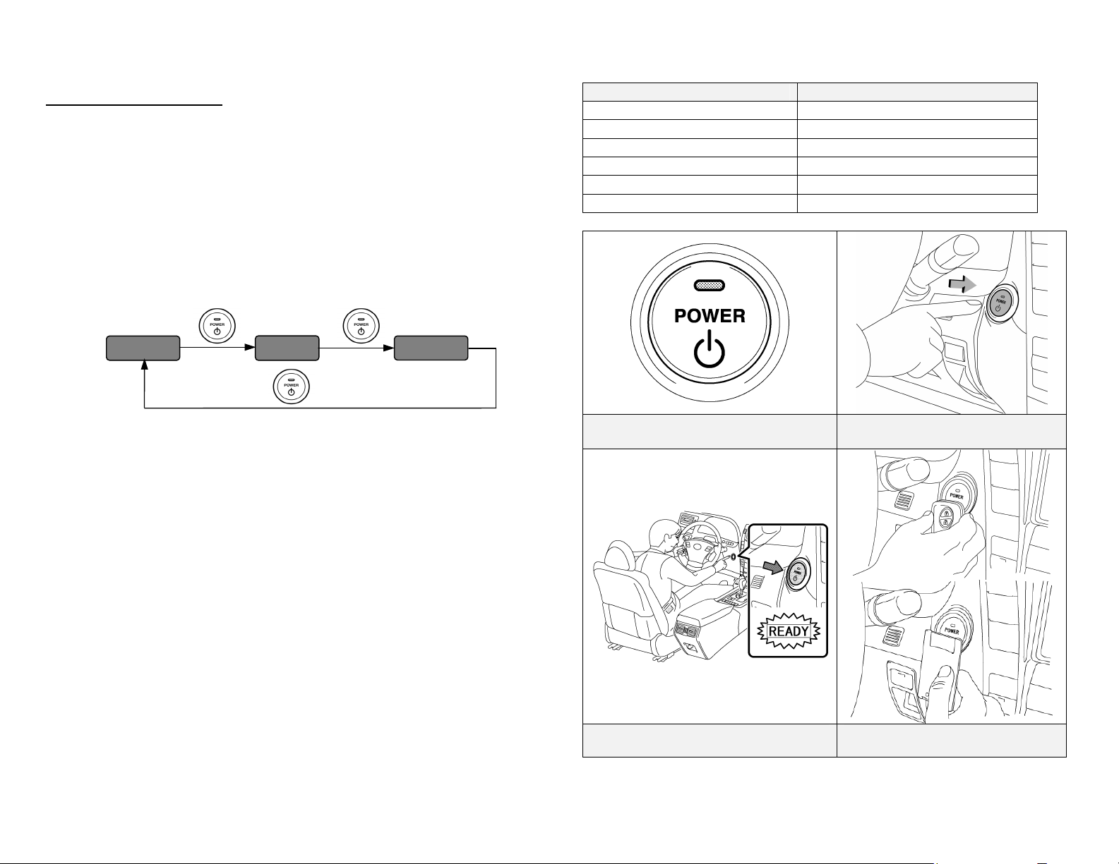
• With the brake pedal released, the first push of the power button
operates the accessory mode, the second push operates the ignition-on
mode, and the third push turns the ignition off again.
Ignition Mode Sequence (brake pedal released):
Vehicle Off
Button Push
Accessory
Button Push
Ignition-On
Ignition Mode Power Button Indicator Light
Off Off
Accessory Amber
Ignition-On Amber
Brake Pedal Depressed Green
Vehicle Started (READY-ON) Off
Malfunction Blinking Amber
Button Push
• Starting the vehicle takes priority over all other ignition modes and is
accomplished by depressing the brake pedal and pushing the power
button once. To verify the vehicle has started, the power button status
indicator light is off and the READY light is illuminated in the
instrument cluster.
• If the internal smart key battery is dead, use the following method to
start the vehicle.
1. Touch the Lexus emblem side of the smart key to the power
button (a buzzer will sound).
2. Within 10 seconds after the buzzer sounds, push the power
button with the brake pedal depressed (the READY light will
illuminate).
• Once the vehicle has started and is on and operational (READY-ON),
the vehicle is shut off by bringing the vehicle to a complete stop, placing
the gearshift lever in Park, and then depressing the power button once.
Power Button with Integral Status
Indicator Light
Starting Sequence
(Brake Pedal Depressed)
Ignition Modes (Brake Pedal
Released)
Smart Key Recognition
(When Smart Key Battery is Dead)
-9-
Page 13
Lexus Hybrid Drive Operation
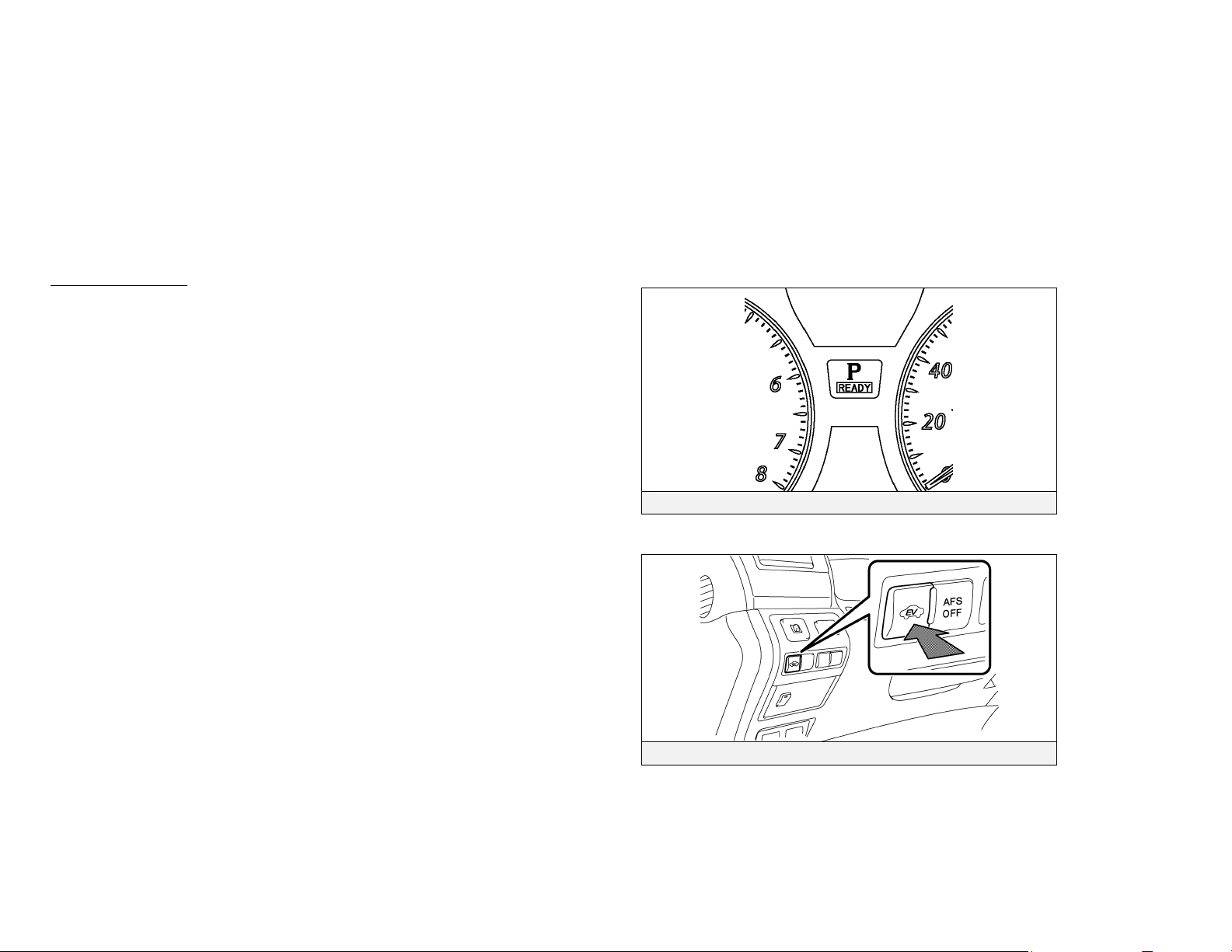
Once the READY indicator is illuminated in the instrument cluster,
the vehicle may be driven. However, the gasoline engine does not
idle like a typical automobile and will start and stop automatically. It
is important to recognize and understand the READY indicator
provided in the instrument cluster. When lit, it informs the driver that
the vehicle is on and operational even though the gasoline engine may
be off and the engine compartment is silent.
Vehicle Operation
• With the LS 600h L, the gasoline engine may stop and start at any time
while the READY indicator is on.
• Never assume that the vehicle is shut off just because the engine is off.
Always look for the READY indicator status. The vehicle is shut off
when the READY indicator is off.
• The vehicle may be powered by:
1. The electric motor only.
2. The gasoline engine only.
3. A combination of both the electric motor and the gasoline
engine.
• The vehicle computer determines the mode in which the vehicle operates
in order to improve fuel economy and reduce emissions. A new feature
on the LS 600h L is EV (Electric Vehicle) drive mode. When activated,
and certain conditions have been met, the vehicle operates with the
electric motor powered by the HV battery.
Instrument Cluster READY Indicator
-10-
EV Mode Switch
Page 14
•
•
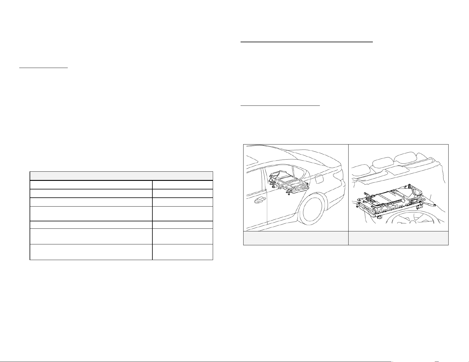
Hybrid Vehicle (HV) Battery Pack
The LS 600h L features a high voltage Hybrid Vehicle (HV) battery pack
that contains sealed Nickel Metal Hydride (NiMH) battery modules.
HV Battery Pack
• The HV battery pack is enclosed in a metal case and is securely mounted in
the trunk area behind the rear seat. The metal case is isolated from high
voltage and concealed by fabric covers.
• The HV battery pack consists of 20 low voltage (14.4 Volt) NiMH battery
modules connected in series to produce approximately 288 Volts. Each
NiMH battery module is non-spillable and sealed in a metal case.
• The electrolyte used in the NiMH battery module is an alkaline mixture of
potassium and sodium hydroxide. The electrolyte is absorbed into the
battery cell plates and will not normally leak, even in a collision.
• In the unlikely event that the battery pack is overcharged, the modules vent
gases directly outside the vehicle through a vent hose.
HV Battery Pack
Battery pack voltage
Number of NiMH battery modules in the pack
NiMH battery module voltage
NiMH battery module dimensions
NiMH module weight
NiMH battery Pack dimensions
(515 x 842 x 257 mm)
NiMH battery Pack weight
288 V
20
14.4 V
1 x 21 x 3.3 in
(18 x 542 x 86 mm)
4.8lbs (2.2kg)
20 x 33x 10 in
148 lbs
(67 kg)
Components Powered by the HV Battery Pack
Electric Motor
• Power Control Unit • Electric Generator
• A/C Compressor
• DC-DC Converter for 12 Volt Auxiliary Battery
• DC-DC Converter for EPS and Active Stabilizer Suspension System
Power Cables
HV Battery Pack Recycling
• The HV battery pack is recyclable. Contact the nearest Lexus dealer or:
United States: (800) 255-3987, Canada: (800) 265-3987
HV Battery Pack
HV Battery Pack
(Viewed from the Trunk)
-11-
Page 15
r
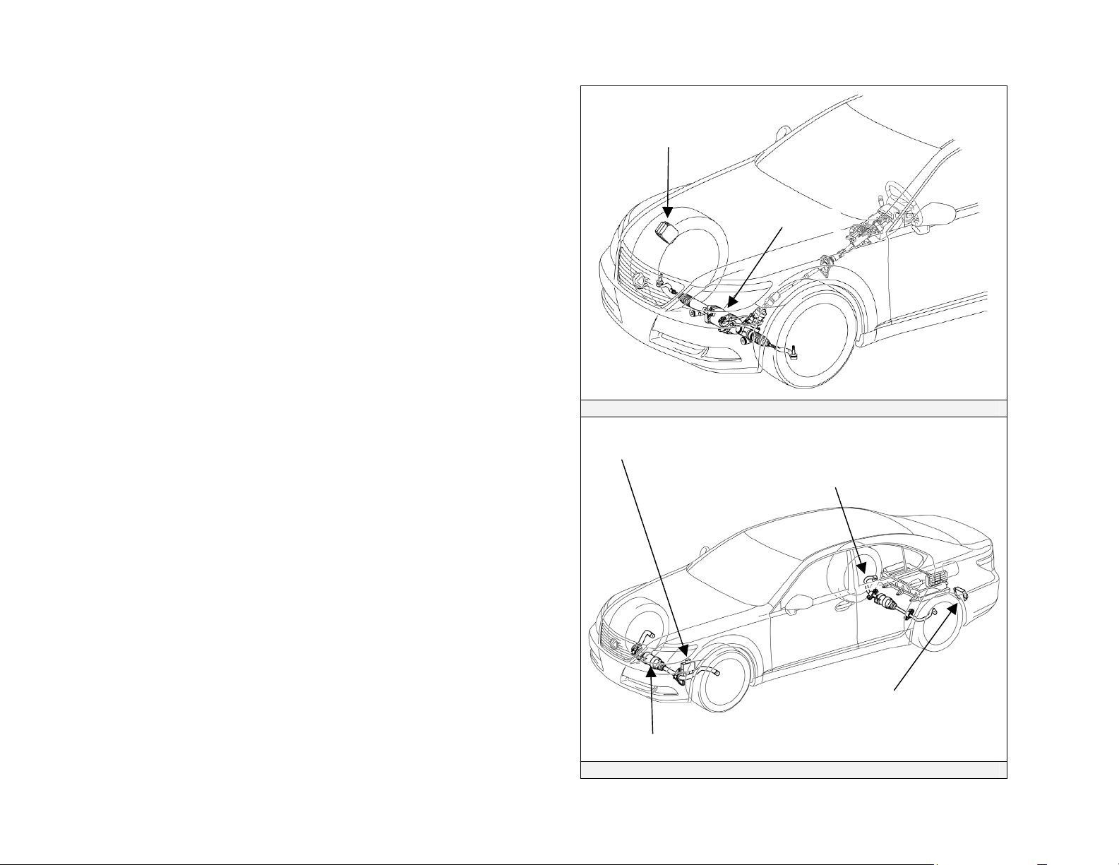
46 Volt System
The LS 600h L is equipped with a 46 Volt electrical system that powers the
Electric Power Steering (EPS) assist motor in the engine compartment and the
optional Active Stabilizer Suspension System motors for the front and rear
stabilizer bars.
• 46 Volt electrical system wires are bundled in dull yellow sheathing for
identification.
• The 46 Volt electrical system does not contain a storage battery. It is
powered by converting high voltage battery power. The wires are routed
underneath the vehicle from the HV battery pack DC-DC converter.
• If the HV battery pack malfunctions, backup power is provided to the EPS
motor by boosting the 12 Volt electrical system.
NOTE:
46 Volts has a higher arc potential than 12 Volts.
Electric Power Steering
ECU
46 Volt Electric Power Steering System
Front Active Stabilizer Control
Front Active Stabilizer Motor
Optional 46 Volt Active Stabilizer Suspension System
Assist Motor
Rear Active Stabilizer Control
ECU
Rear Active Stabilizer
Moto
-12-
Page 16
Low Voltage Battery
Auxiliary Battery
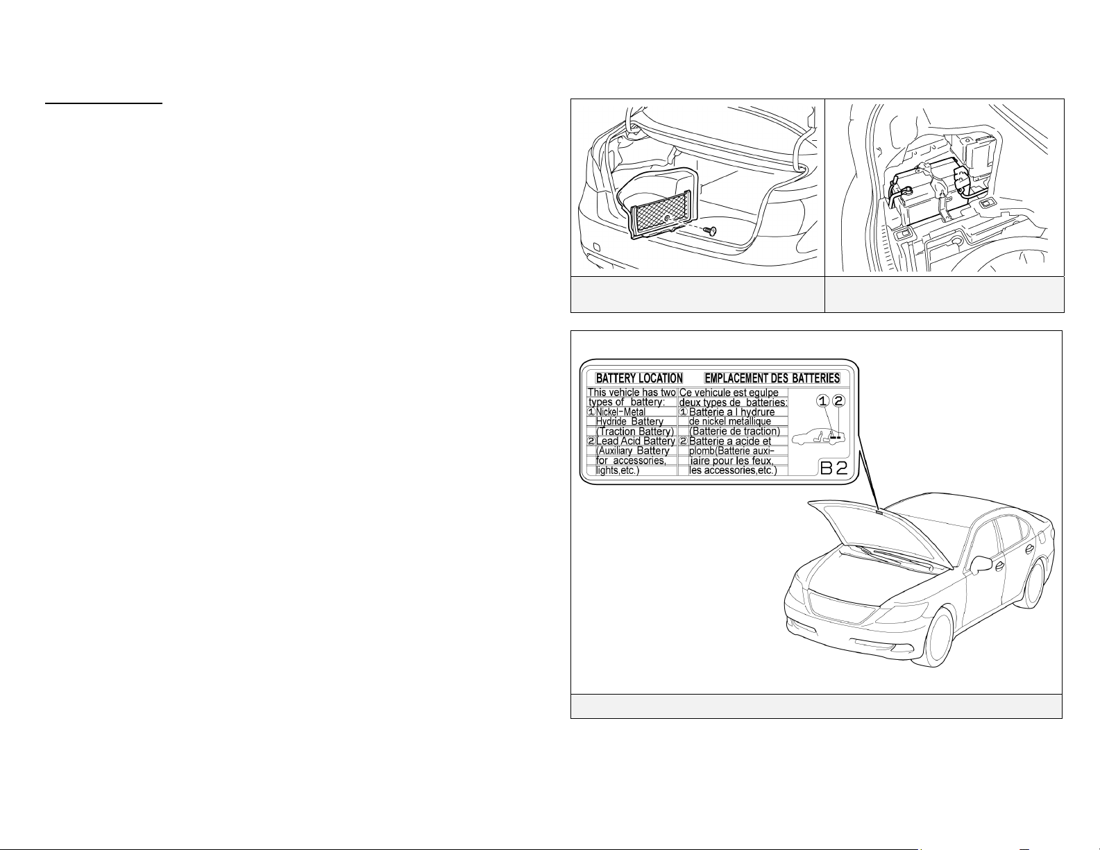
• The LS 600h L contains a sealed lead-acid 12 Volt battery. The 12 Volt
auxiliary battery powers the vehicle’s electrical system similar to a
conventional vehicle. As with conventional vehicles, the negative terminal
of the auxiliary battery is grounded to the metal chassis of the vehicle.
• The auxiliary battery is located in the trunk. It is concealed by a fabric
cover on the driver side in the rear quarter panel well.
NOTE:
An underhood label shows the location of the HV battery (traction battery)
and 12 Volt auxiliary battery.
12 Volt Auxiliary Battery Fabric Cover
12 Volt Auxiliary Battery Mounted in
Trunk (Driver Side)
-13-
Battery Location Label
Page 17
p
High Voltage Safety
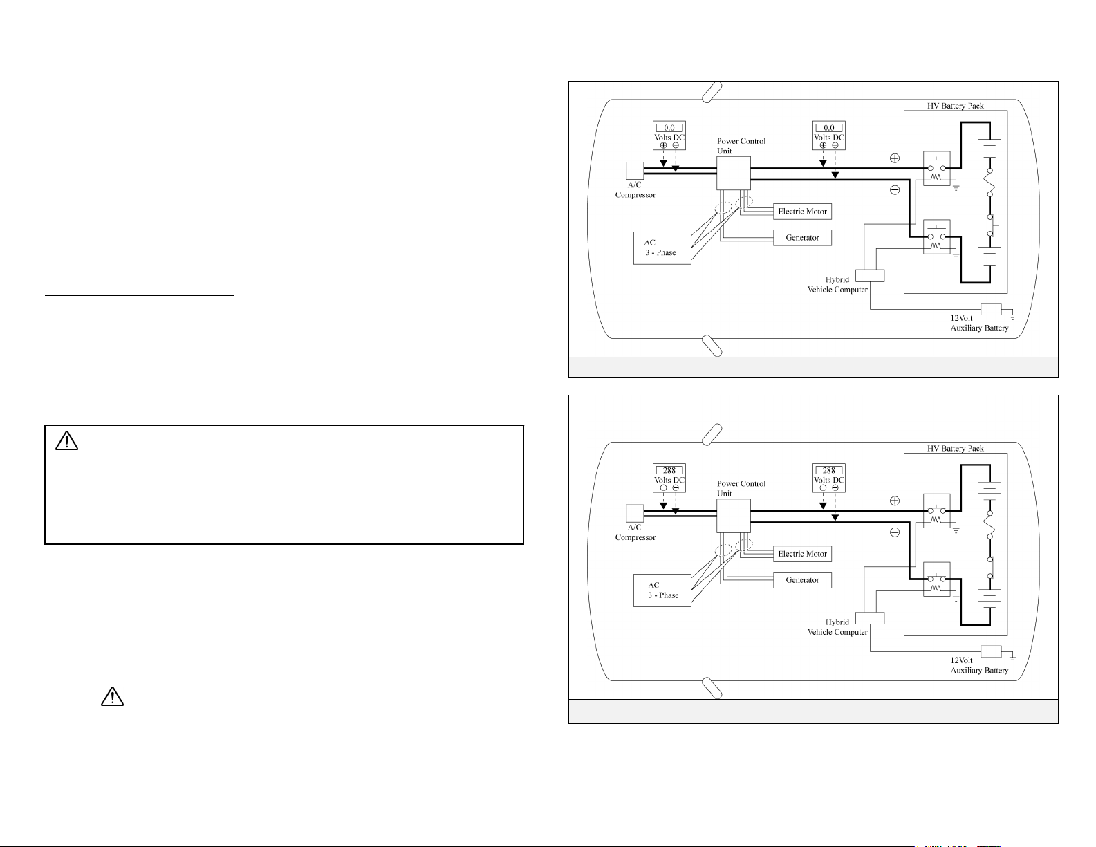
The HV battery pack powers the high voltage electrical system with DC
electricity. Positive and negative orange colored high voltage power cables are
routed from the battery pack, under the vehicle floor pan, along the propeller
shaft and transmission tunnel to the power control unit. The power control unit
contains a circuit that boosts the HV battery voltage from 288 to 650 Volts DC.
The power control unit creates 3-phase AC to power the motor and generator
located in the transmission. Power cables are routed from the power control
unit to each high voltage motor (electrical motor, electric generator, and A/C
compressor). The following systems are intended to help keep occupants in the
vehicle and emergency responders safe from high voltage electricity:
High Voltage Safety System
• A high voltage fuse provides short circuit protection in the HV battery
pack.
• Positive and negative high voltage power cables connected to the HV
battery pack are controlled by 12 Volt normally open relays . When the
vehicle is shut off, the relays stop electrical flow from leaving the HV
battery pack.
High Voltage Safety System – Vehicle Shut Off (READY-OFF)
WARNING:
The high voltage system may remain powered for up to 10 minutes
after the vehicle is shut off or disabled. To prevent serious injury or
death from severe burns or electric shock, avoid touching, cutting, or
breaching any orange high voltage power cable or high voltage
com
onent.
• Both positive and negative power cables are insulated from the metal
chassis, so there is no possibility of electric shock when touching the metal
chassis.
• A ground fault monitor continuously monitors for high voltage leakage
to the metal chassis while the vehicle is running. If a malfunction is
detected, the hybrid vehicle computer will illuminate the master warning
light
in the instrument cluster and indicate “CHECK HYBRID
SYSTEM” on the multi-information display.
High Voltage Safety System – Vehicle On and Operational (READY-ON)
-14-
Page 18
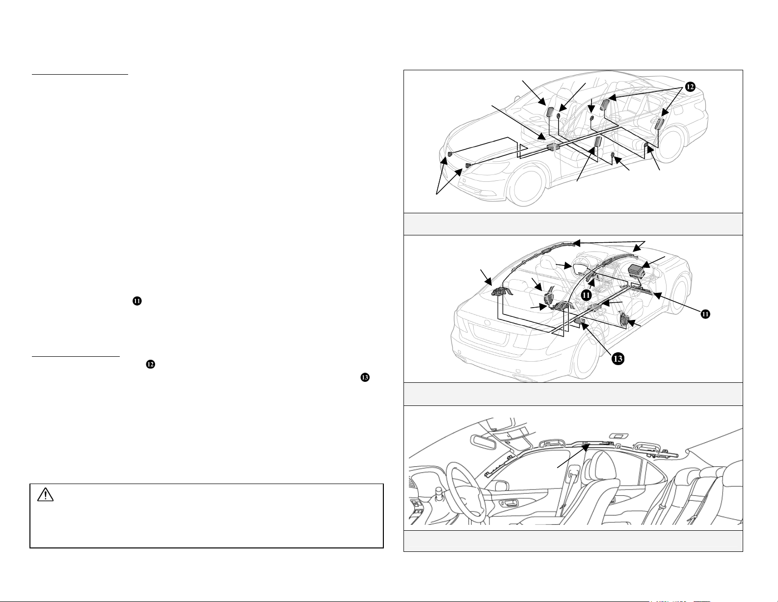
SRS Airbags & Seat Belt Pretensioners
Standard Equipment
• Electronic frontal impact sensors (2) are mounted in the engine
compartment as illustrated.
• Front seat belt pretensioners are mounted near the base of the B-pillars .
• Rear seat belt pretensioners are mounted near the C-pillar on the rear
seatbacks.
• A frontal dual stage driver airbag is mounted in the steering wheel hub.
• A frontal twin-chamber shaped dual stage passenger airbag is integrated
into the dashboard and deploys through the top of the dashboard.
• The SRS computer , which contains an impact sensor, is mounted on the
floor pan underneath the center armrest console.
• Front electronic side impact sensors (2) are mounted near the base of the Bpillars .
• Rear electronic side impact sensors (2) are mounted near the base of the Cpillars .
• Front seat side airbags are mounted in the seatbacks.
• Side curtain airbags are mounted along the outer edge inside the roof
rails.
• Front knee airbags
lower portion of the dash.
Optional Equipment
• Rear seat side airbags
• The optional passenger side rear ottoman power seat contains an airbag
mounted in the bottom seat cushion.
• The optional pre- collision safety system contains a radar sensory system,
occupant seat sensor, and an electric motor-pyrotechnic pretensioner
system. During a pre-collision event, an electric motor in the pretensioners
retracts the slack in the front seatbelt. When conditions stabilize the electric
motor will reverse itself. When the airbags deploy, the pyrotechnic
pretensioners function normally.
are mounted on the driver side and passenger side
mounted in the rear seats are optional equipment.
Electronic Impact Sensors, Front and Optional Rear Seat Side Airbags
Standard Frontal Airbags, Seat Belt Pretensioners, Knee Airbags, Side Curtain
Airbags, and Optional Seat Cushion Airbag
WARNING:
The SRS may remain powered for up to 90 seconds after the vehicle is shut off
or disabled. To prevent serious injury or death from unintentional SRS
deployment, avoid breaching the SRS components.
Side Curtain Airbag Inflator in Roof Rail
-15-
Page 19
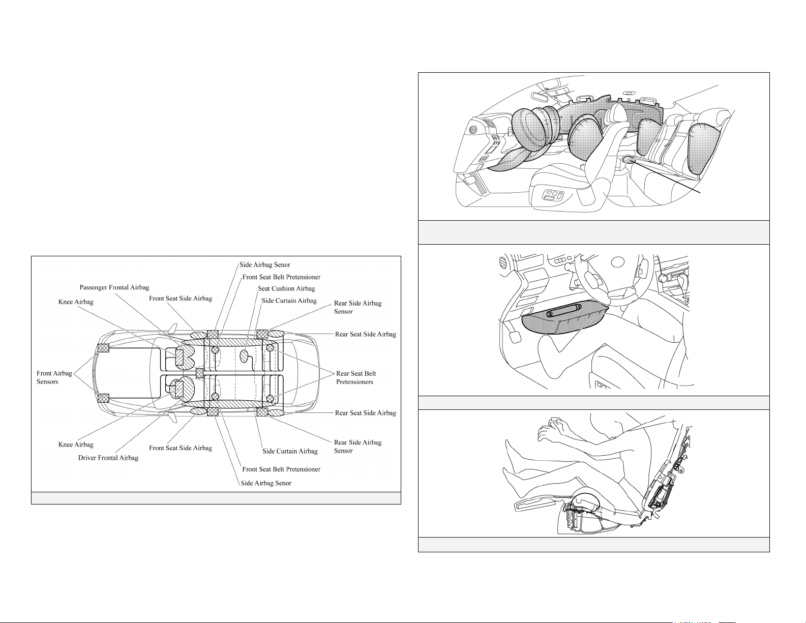
SRS Airbags & Seat Belt Pretensioners (Continued)
NOTE:
The front seatback mounted side airbags and the side curtain airbags may
deploy independently of each other.
The knee airbags deploy simultaneously with the frontal airbags and seat
belt pretensioners.
The LS 600h L is equipped with a standard front passenger occupant
classification system that may prohibit the deployment of the front
passenger frontal airbag, knee airbag, seatback mounted side airbag, and
seat belt pretensioners. If the passenger occupant classification system
prohibits deployment during an SRS event, the passenger SRS will not rearm nor deploy.
Optional
Ottoman with
Seat Cushion
Airbag
Frontal, Knee, Front Seatback Mounted Side, Side Curtain, Optional Rear Seat
Side and Seat Cushion Airbags.
Driver Knee Airbag and Inflator
SRS System Diagram
Passenger Side Rear Seat Cushion Airbag (Standard with Optional Ottoman Seat)
-16-
Page 20
Emergency Response
On arrival, emergency responders should follow their standard
operating procedures for vehicle incidents. Emergencies involving the
LS 600h L may be handled like other automobiles except as noted in
these guidelines for Extrication, Fire, Overhaul, Recovery, Spills, First
Aid, and Submersion.
WARNING:
• Never assume the LS 600h L is shut off simply because it is silent.
• Always observe the instrument cluster for the READY indicator
status to verify whether the vehicle is on or shut off. The vehicle is
shut off when the READY indicator is off.
• Failure to shut off the vehicle before emergency response
procedures are performed may result in serious injury or death
from the unintentional deployment of the SRS or severe burns and
electric shock from the high voltage electrical system.
Extrication
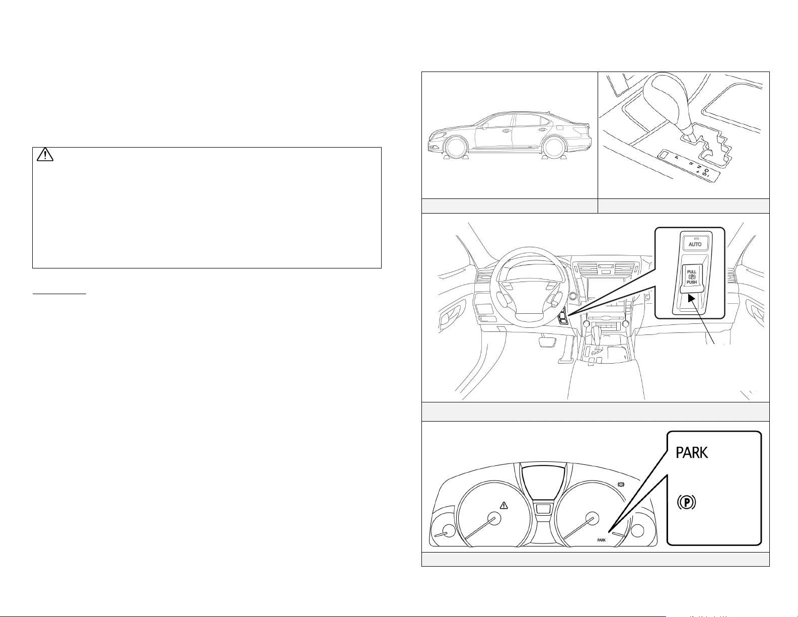
• Immobilize Vehicle
Chock wheels and set the parking brake.
Move the shift lever to the Park position.
NOTE:
The LS 600h L utilizes a push/pull parking brake switch that electromechanically sets/releases the rear parking brakes.
− To set/release, push/pull the parking brake switch located on the
dash to the right side of the steering column (refer to illustration).
− If the AUTO button is set and illuminated, the parking brake will
automatically set when the vehicle is shifted to the Park position.
− To verify that the parking brake is set, confirm that the PARK
light illuminates on the instrument cluster (refer to illustration).
The PARK light will turn off after approximately 15 seconds.
• Disable Vehicle
Performing either of the following two procedures will shut the
vehicle off and disable the HV battery pack, SRS, and gasoline fuel
pump.
Chock Wheels Shift Lever in Park
Parking Brake Switch
Push: Set
Pull: Release
Set Parking Brake
Parking Brake Indicator Light
For USA
For CANADA
-17-
Page 21
Emergency Response (Continued)
Extrication (Continued)
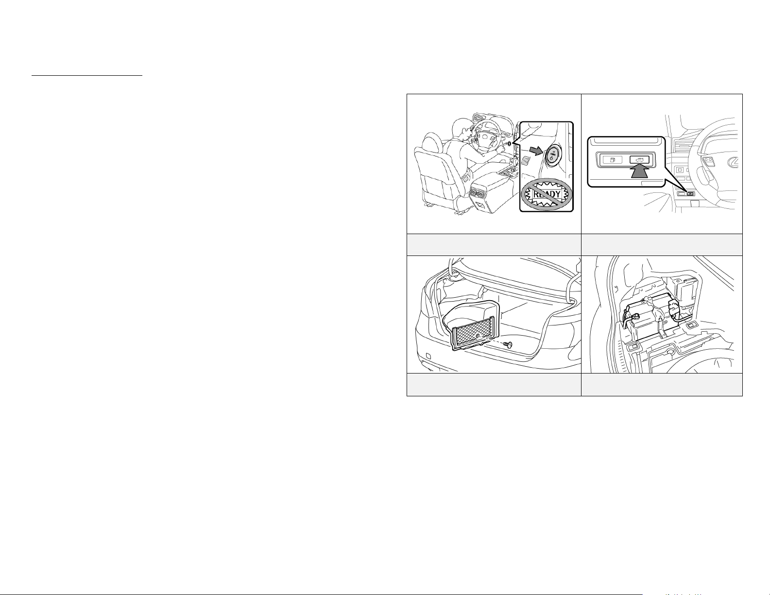
Procedure #1
1. Confirm the status of the READY indicator in the instrument
cluster.
2. If the READY indicator is illuminated, the vehicle is on and
operational. Shut off the vehicle by pushing the power button
once.
3. The vehicle is already shut off if the instrument cluster lights and
the READY indicator are not illuminated. Do not push the
power button because the vehicle may start.
4. If the smart key is easily accessible, keep it at least 16 feet (5
meters) away from the vehicle.
5. If the smart key cannot be found, disconnect the 12 Volt auxiliary
battery in the trunk to prevent accidental restarting of the vehicle.
Shut Off Vehicle (READY-Off) Electric Trunk Opener Switch
-18-
Remove 12 Volt Auxiliary Battery
Fabric Cover
12 Volt Auxiliary Battery in Trunk
(Driver Side)
Page 22
Emergency Response (Continued)
Extrication (Continued)
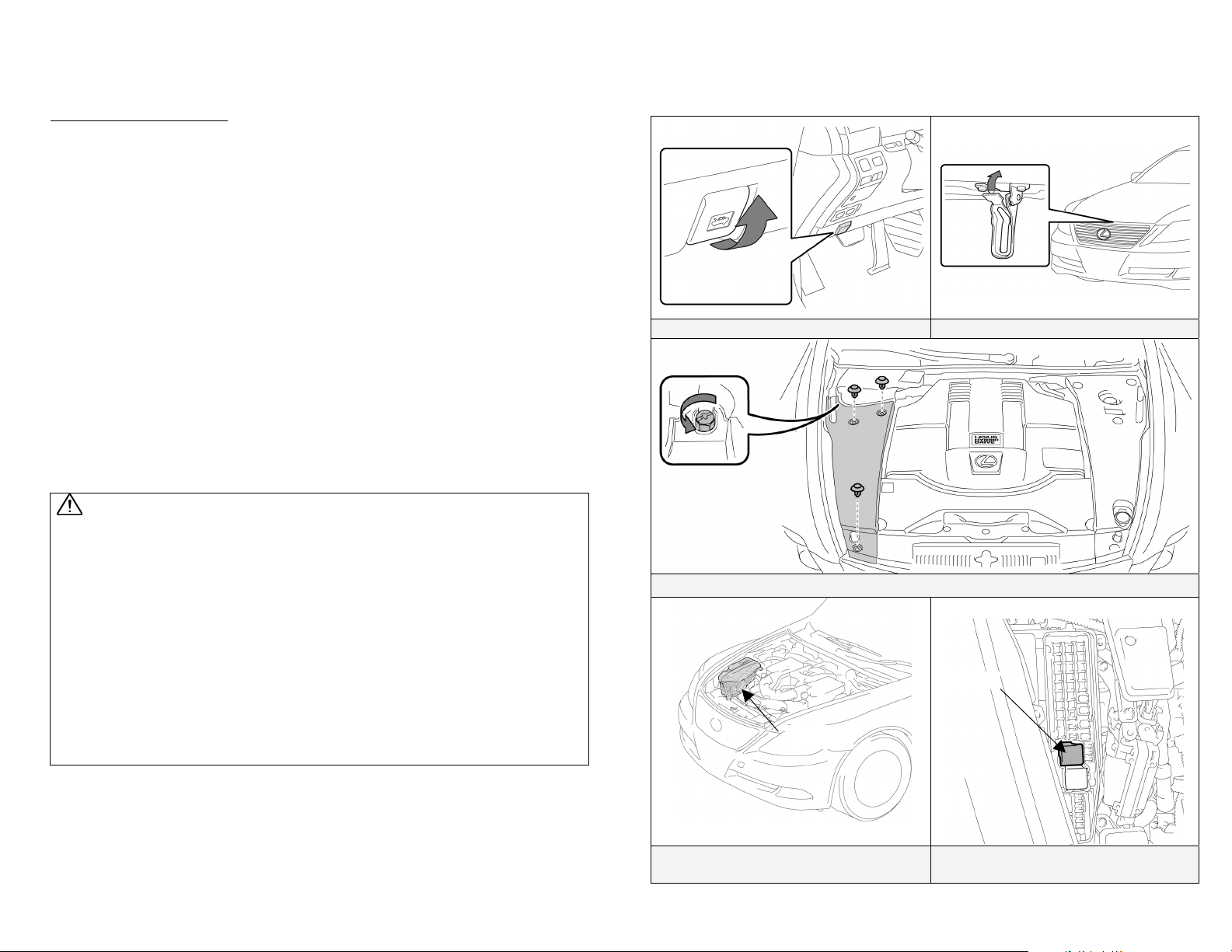
Procedure #2 (Alternate if power button is inaccessible)
1. Remove the engine compartment and fuse box covers.
2. Remove the IG2 relay in the engine compartment fuse box (refer
to illustration). If the correct relay cannot be recognized, pull
both relays in the fuse box.
3. Disconnect the 12 Volt auxiliary battery in the trunk.
NOTE:
Before disconnecting the 12 Volt auxiliary battery, if necessary, set
the parking brake, reposition the power seats, tilt/telescoping steering
wheel, lower the windows, unlock the doors, open the trunk and the
fuel door as required. A manual fuel door release is located in the
trunk (see the illustration in the Roadside Assistance section on page
28). Once the 12 Volt auxiliary battery is disconnected, power
controls will not operate.
WARNING:
• The high voltage system may remain powered for up to 10 minutes
after the vehicle is shut off or disabled. To prevent serious injury
or death from severe burns or electric shock, avoid touching,
cutting, or breaching any orange high voltage power cable or high
voltage component.
• The SRS may remain powered for up to 90 seconds after the vehicle
is shut off or disabled. To prevent serious injury or death from
unintentional SRS deployment, avoid breaching the SRS
components.
• If none of the disabling procedures can be performed, proceed with
caution as there is no assurance that the high voltage electrical
system, SRS, or fuel pump are disabled
.
Remote Hood Release Hood Latch Release
Remove Engine Compartment Cover
IG2 Relay
Fuse box
Remove Fuse Box Cover
IG2 Relay Location in Engine
Compartment Fuse Box
-19-
Page 23
Emergency Response (Continued)
Extrication (Continued)
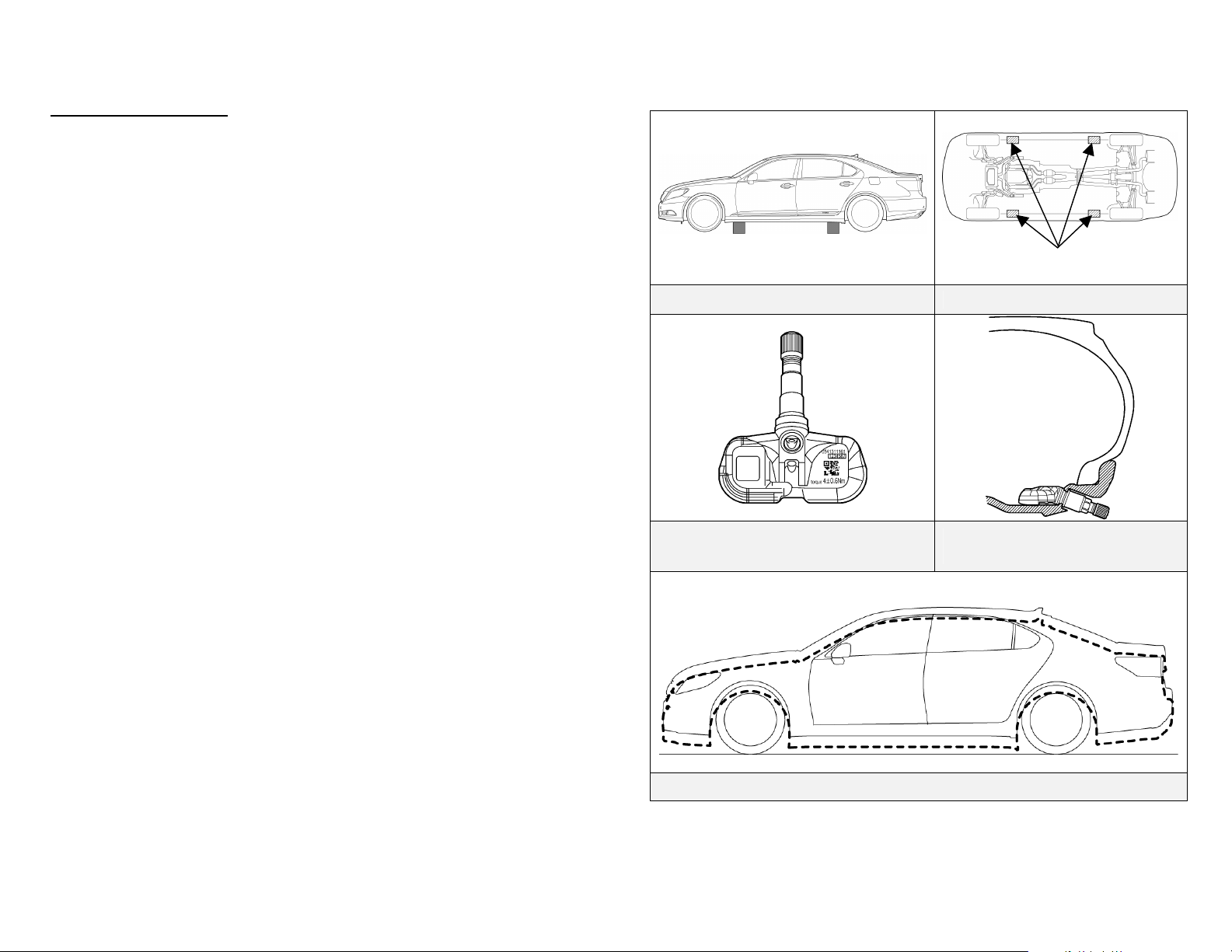
• Stabilize Vehicle
Crib at (4) points directly under the front and rear pillars.
Do not place cribbing under the high voltage power cables, exhaust
system, or fuel system.
NOTE:
The LS 600h L is equipped with a tire pressure warning system that
by design prevents pulling the metal valve stem with integral
transmitter from the wheel. Snapping the stem with pliers or
removing the valve cap and Schrader valve will release the air in the
tire.
The LS 600h L is equipped with an air suspension system. In the
event of a collision, fire or malfunction, air leakage may occur,
allowing the body to drop.
• Access Patients
Glass Removal
The LS 600h L is equipped with laminated side windows having
similar properties as laminated windshield glass. If side glass
removal is required, use the same techniques as the front
windshield glass.
Types of glazing found on the LS 600h L
− Laminated front windshield
− Laminated side windows
− Tempered rear window
SRS Awareness
Responders need to be cautious when working in close proximity
to undeployed airbags and seat belt pretensioners. Front dual
stage airbags automatically ignite both stages within a fraction of
a second.
Door Removal/Displacement
Doors can be removed by conventional rescue tools such as hand,
electric, and hydraulic tools. In certain situations, it may be
easier to pry back the vehicle body to expose and unbolt the
hinges.
Cribbing Points Underbody View
Tire Pressure Sensor Metal Valve Stem
with Integral Transmitter.
Air Suspension System Drop
Cribbing Points
Metal Valve Stem with Integral
Transmitter Installed on Wheel
-20-
Page 24
Emergency Response (Continued)
Extrication (Continued)
Roof Removal
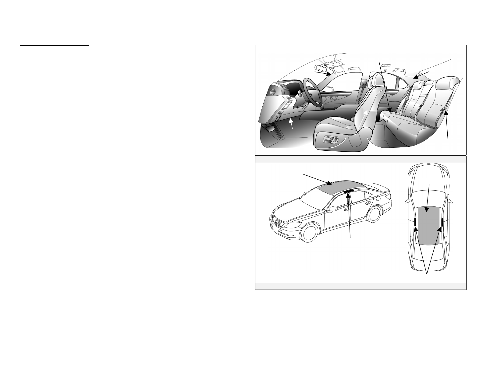
The LS 600h L is equipped with side curtain airbags.
When undeployed, total roof removal is not recommended.
Patient access through the roof can be performed by cutting the
roof center section inboard of the roof rails as illustrated. This
would avoid breaching the side curtain airbags, inflators, and
wiring harness.
NOTE:
The side curtain airbags may be identified as illustrated on this page
(additional component details on page 15).
Dash Displacement
The LS 600h L is equipped with side curtain airbags. When
undeployed, total roof removal is not recommended to avoid
breaching the side curtain airbags, inflators, and wiring harness.
As an alternative, dash displacement may be performed by using
a Modified Dash Roll.
Removable Area
SRS SEAT CUSHION AIRBAG
(Only with Ottoman)
SRS CURTAIN
AIRBAG
SRS KNEE
AIRBAG
SRS SIDE
AIRBAG
Side, Side Curtain, Knee, and Cushion Airbag Identifiers.
SRS CURTAIN
AIRBAG
SRS SIDE
AIRBAG
Removable Area
-21-
Driver Side Curtain
Airbag Inflator
Side Curtain Airbag Inflators
Roof Removal Area
Page 25
Emergency Response (Continued)
Extrication (Continued)
Rescue Lift Air Bags
Responders should not place cribbing or rescue lift air bags under
the high voltage power cables, exhaust system, or fuel system.
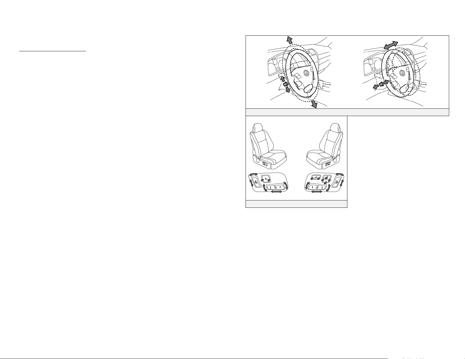
Repositioning Steering Wheel and Front Seats
Power tilt/telescopic steering wheel and seat controls are shown
in the illustrations.
NOTE:
The LS 600h L is equipped with front seat power adjustable headrests
using the power seat controls. The headrest cannot be removed.
Reposition the seat and headrest prior to disconnecting the 12 Volt
auxiliary battery.
Power Tilt and Telescoping Controls
-22-
Front Power Seat Controls
Page 26
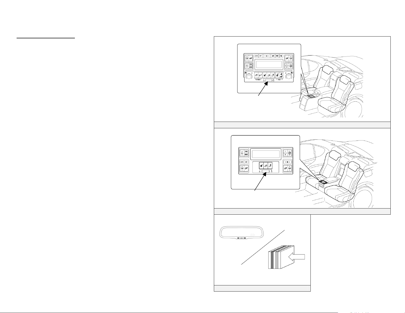
Emergency Response (Continued)
Extrication (Continued)
Repositioning Rear Seats
Power adjustable rear seats are standard in the LS 600h L. The
rear seat control panel shown in the illustration should be used if
it is necessary to adjust the rear seat position.
Before adjusting the position of a rear seat, select either the left
or right hand seat using the selection switch.
NOTE:
In the event that a rear door is opened, the optional rear seat ottoman
may automatically fold closed. To prevent the rear seat from
retracting, disconnect the 12 Volt auxiliary battery before opening the
rear doors.
The LS 600h L has an electrochromic auto dimming rear view mirror.
The mirror contains a minimal amount of transparent gel sealed
between two glass plates that will not normally leak.
Selection Switch
Rear Power Seat Control Panel (4 Passenger with Optional Ottoman Seat)
-23-
Selection Switch
Rear Power Seat Control Panel (5 Passenger)
Mirror Cross
Section
Sealed Electrochromic coating
Electrochromic Auto Dimming Mirror
Page 27

Emergency Response (Continued)
Fire
Approach and extinguish a fire using proper vehicle fire fighting practices as
recommended by NFPA, IFSTA, or the National Fire Academy (USA).
• Extinguishing Agent
Water has been proven to be a suitable extinguishing agent.
• Initial Fire Attack
Perform a fast, aggressive fire attack.
Divert the runoff from entering watershed areas.
Attack teams may not be able to identify an LS 600h L until the fire
has been knocked down and overhaul operations have commenced.
NOTE:
The LS 600h L is equipped with an air suspension system. In the
event of fire, air leakage may occur, allowing the body to drop.
• Fire in the HV Battery Pack
Should a fire occur in the NiMH HV battery pack, attack crews
should utilize a water stream or fog pattern to extinguish any fire
within the trunk except
WARNING:
• The NiMH battery electrolyte is a caustic alkaline (pH 13.5)
that is damaging to human tissues. To avoid injury by
coming in contact with the electrolyte, wear proper personal
protective equipment.
• The battery modules are contained within a metal case and
accessibility is limited.
• To avoid serious injury or death from severe burns or
electric shock, never breach or remove the high voltage
battery pack cover under any circumstance including fire.
When allowed to burn themselves out, the LS 600h L NiMH battery
modules burn rapidly and can quickly be reduced to ashes except for
the metal.
for the HV battery pack.
Offensive Fire Attack
Normally
water at a safe distance will effectively control the HV battery pack
fire by cooling the adjacent NiMH battery modules to a point below
their ignition temperature. The remaining modules on fire, if not
extinguished by the water, will burn themselves out.
However, flooding the LS 600h L HV battery pack is not
recommended due to the battery case design and location preventing
the responder from properly applying water through the available vent
openings safely. Therefore, it is recommended that the incident
commander allow the LS 600h L HV battery pack to burn itself out.
Defensive Fire Attack
If the decision has been made to fight the fire using a defensive attack,
the fire attack crew should pull back a safe distance and allow the
NiMH battery modules to burn themselves out. During this defensive
operation, fire crews may utilize a water stream or fog pattern to
protect exposures or to control the path of smoke.
flooding a NiMH HV battery pack with copious amounts of
-24-
Page 28

Emergency Response (Continued)
Overhaul
During overhaul, immobilize and disable the vehicle if not already done.
Refer to illustrations on page 17. The HV battery cover should never be
breached or removed under any circumstances including fire. Doing so may
result in severe electrical burns, shock, or electrocution.
• Immobilize Vehicle
Chock wheels and set the parking brake.
Move the shift lever to the Park position.
NOTE:
The LS 600h L utilizes a push/pull parking brake switch that electromechanically sets/releases the rear parking brakes.
− To set/release, push/pull the parking brake switch located on
the dash to the right side of the steering column (refer to
illustration on page 17).
− If the AUTO button is set and illuminated, the parking brake
will automatically set when the vehicle is shifted to the Park
position.
− To verify that the parking brake is set, confirm that the PARK
light illuminates on the instrument cluster (refer to illustration
on page 17). The PARK light will turn off after approximately
15 seconds.
• Disable Vehicle
Performing either of the following two procedures will shut the
vehicle off and disable the HV battery pack, SRS, and gasoline fuel
pump.
Procedure #1
1. Confirm the status of the READY indicator in the instrument
cluster.
2. If the READY indicator is illuminated, the vehicle is on and
operational. Shut off the vehicle by pushing the power button
once.
3. The vehicle is already shut off if the instrument cluster lights and
the READY indicator are not illuminated. Do not push the
power button because the vehicle may start.
4. If the smart key is easily accessible, keep it at least 16 feet (5
meters) away from the vehicle.
5. If the smart key cannot be found, disconnect the 12 Volt
auxiliary battery in the trunk to prevent accidental restarting of
the vehicle.
Procedure #2 (Alternate if power button is inaccessible)
1. Remove the engine compartment and fuse box covers.
2. Remove the IG2 relay in the engine compartment fuse box as
illustrated on page 19.
pull both relays in the fuse box.
3. Disconnect the 12 Volt auxiliary battery in the trunk.
• Stabilize Vehicle
If not already done, properly crib the vehicle to prevent the vehicle
body from dropping.
If the correct relay cannot be recognized,
Recovering/Recycling of NiMH HV Battery Pack
Clean up of the HV battery pack can be accomplished by the vehicle recovery
crew without further concern of runoff or spillage. For information regarding
recycling of the HV battery pack, contact the nearest Lexus dealer, or:
United States: (800) 255-3987, Canada: (800) 265-3987
-25-
Page 29

Emergency Response (Continued)
Spills
The LS 600h L contains the same common automotive fluids used in other
non-hybrid Lexus vehicles, with the exception of NiMH electrolyte used in
the HV battery pack. The NiMH battery electrolyte is a caustic alkaline (pH
13.5) that is damaging to human tissues. The electrolyte, however, is absorbed
in the cell plates and will not normally spill or leak out even if a battery
module is cracked. A catastrophic crash that would breach both the metal
battery pack case and a metal battery module would be a rare occurrence.
Similar to the use of baking soda to neutralize a lead-acid battery electrolyte
spill, a dilute boric acid solution or vinegar can be used to neutralize a NiMH
battery electrolyte spill.
NOTE:
Electrolyte leakage from the HV battery pack is unlikely due to its
construction and the amount of available electrolyte contained within the
NiMH modules. Any spillage would not warrant a declaration as a hazardous
material incident. Responders should follow the recommendations as outlined
in this emergency response guide.
In an emergency, Material Safety Data Sheets (MSDS) are available by
contacting:
United States: CHEMTREC at (800) 424-9300
Canada: CANUTEC at *666 or (613) 996-6666 (collect)
• Handle NiMH electrolyte spills using the following Personal Protective
Equipment (PPE):
Splash shield or safety goggles. Fold down helmet shields are not
acceptable for acid or electrolyte spills.
Rubber, latex or nitrile gloves.
Apron suitable for alkaline.
Rubber boots.
• Neutralize NiMH Electrolyte
Use a boric acid solution or vinegar.
Boric acid solution - 800 grams boric acid to 20 liters water or 5.5
ounces boric acid to 1 gallon of water.
First Aid
Emergency responders may not be familiar with a NiMH electrolyte exposure
when rendering aid to a patient. Exposure to the electrolyte is unlikely except
in a catastrophic crash or through improper handling. Utilize the following
guidelines in the event of exposure.
WARNING:
The NiMH battery electrolyte is a caustic alkaline (pH 13.5) that is
damaging to human tissues. To avoid injury by coming in contact
with the electrolyte, wear proper personal protective equipment.
• Wear Personal Protective Equipment (PPE)
Splash shield or safety goggles. Fold down helmet shields are not
acceptable for acid or electrolyte spills.
Rubber, latex or nitrile gloves.
Apron suitable for alkaline.
Rubber boots.
• Absorption
Perform gross decontamination by removing affected clothing and
properly disposing of the garments.
Rinse the affected areas with water for 20 minutes.
Transport patients to the nearest emergency medical care facility.
• Inhalation in Non-Fire Situations
No toxic gases are emitted under normal conditions.
• Inhalation in Fire Situations
Toxic gases are given off as by-products of combustion. All
responders in the Hot Zone should wear the proper PPE for fire
fighting including SCBA.
Move a patient from the hazardous environment to a safe area and
administer oxygen.
Transport patients to the nearest emergency medical care facility.
• Ingestion
Do not induce vomiting.
Allow a patient to drink large quantities of water to dilute electrolyte
(never give water to an unconscious person).
-26-
Page 30

Emergency Response (Continued)
First Aid (Continued)
If vomiting occurs spontaneously, keep the patient’s head lowered
and forward to reduce the risk of asphyxiation.
Transport patients to the nearest emergency medical care facility.
Submersion
A submerged hybrid vehicle does not have high voltage potential on the metal
vehicle body, and is safe to touch.
Access Patients
Responders can access the patient and perform normal extrication
procedures. High voltage orange color coded power cables and high
voltage components should never be touched, cut, or breached.
Vehicle Recovery
If a hybrid vehicle is fully or partially submerged in water, emergency
responders may not be able to determine if the vehicle has been
automatically disabled. The LS 600h L may be handled by following
these recommendations:
1. Remove the vehicle from the water.
2. Drain the water from the vehicle if possible.
3. Follow the immobilizing and disabling procedures on page 17.
-27-
Page 31
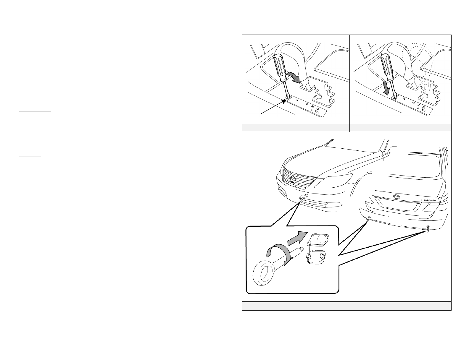
Roadside Assistance
Lexus LS 600h L roadside assistance may be handled like conventional Lexus
vehicles except as noted in the following pages.
Lexus Roadside Assistance is available during the basic warranty period by
contacting:
United States: (800) 255-3987, Canada: (800) 265-3987
Shift Lever
Similar to most Lexus vehicles, the LS 600h L uses a gated shift lever as
shown in the illustration. However, the LS 600h L shift lever includes an S
position for 8 levels of engine braking.
Towing
The LS 600h L is a mechanical all-wheel drive vehicle and it must be towed
with all four wheels off the ground. Failure to do so may cause serious
damage to vehicle components.
• The vehicle may be shifted out of Park into Neutral by turning the
ignition-on, depressing the brake, then moving the gated shift lever to N.
• If the shift lever cannot be moved out of Park, a shift lock release button
is provided under the cover near the shift lever as shown in the illustration.
• If a tow truck is not available, in an emergency the vehicle may be
temporarily towed using a cable or chain secured to the emergency
towing eyelet. This should only be attempted on hard, paved roads for
short distances at low speeds. The eyelet is located with the tools in the
trunk, refer to the illustration on page 29.
Cover
Remove Cover Push in Shift Lock Release
-28-
The vehicle is equipped with one eyelet
Eyelet Installation
Towing Eyelet Mounting Locations
as an in-vehicle tool.
Page 32
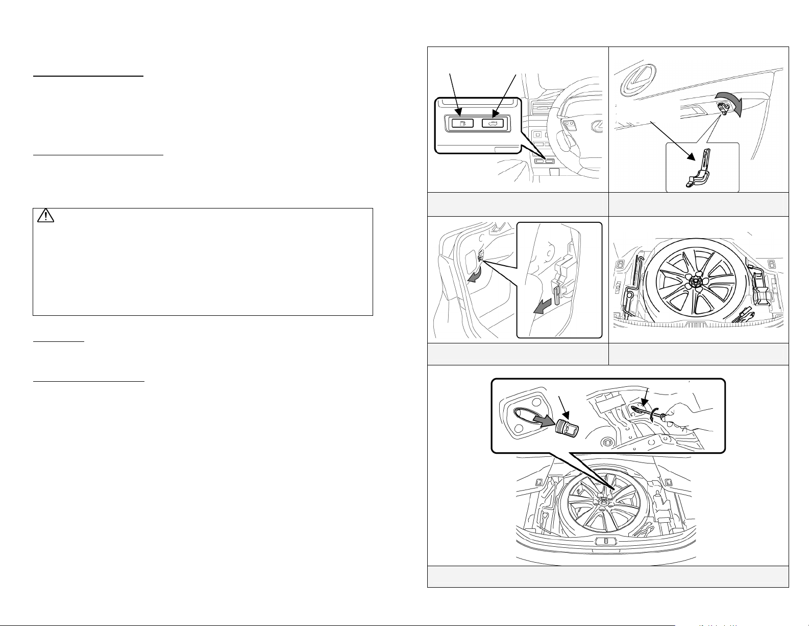
p
y
Roadside Assistance (Continued)
Electric Trunk Opener
The LS 600h L is equipped with an electric trunk opener. In the event of 12
Volt power loss, the trunk can be opened with the metal cut key hidden in the
smart key.
Electric Fuel Door Opener
The LS 600h L is equipped with an electric fuel door opener. In the event of
12 Volt power loss, the fuel door can only be opened using the manual release
located inside the trunk.
WARNING:
The LS 600h L has a fuel vapor containment system that results in the
tank pressure being higher than that of a conventional vehicle. If the
fuel filler cap is removed after using the manual fuel door release, the
vehicle will not automatically reduce the fuel tank pressure. Opening
the fuel cap in this state will allow pressurized fuel vapors to escape, and
fuel may also be discharged from the filler inlet. For these reasons, be
extremely careful and open the fuel cap slowly.
Spare Tire
The jack, tools, and spare tire are provided in the trunk as illustrated.
Electric Parking Brake
The LS 600h L is equipped with an electric parking brake set/release switch.
In the event of a 12 Volt power loss, the parking brake cannot be electrically
operated. The parking brake can be manually released using the on-board
tools.
• Remove the spare tire from inside the trunk.
• Remove the plug as illustrated.
• Insert the vehicle tool in the hole. While pressing firmly on the tool, turn
it counter-clockwise until the parking brake is released.
Fuel Door
O
ener Switch
Electric Fuel Door and Trunk Opener
Manual Fuel Door Release Tools and Spare Tire in the Trunk
Trunk Opener
Switches
Plug
Hidden
Metal Cut Ke
Manual Trunk Opening with the Metal
Cut Key
Vehicle Tool
Manual Parking Brake Release
-29-
Page 33
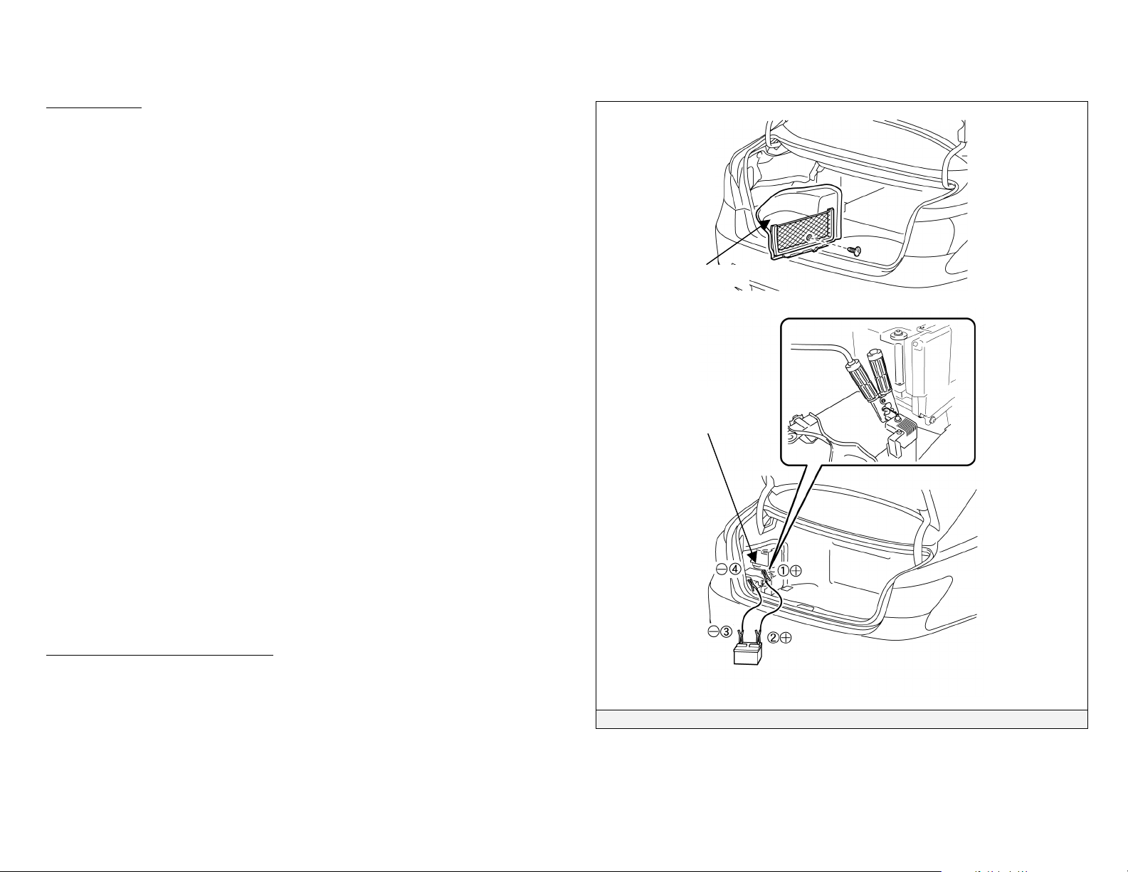
Roadside Assistance (Continued)
Jump Starting
The 12 Volt auxiliary battery may be jump started if the vehicle does not start
and the instrument cluster gauges are dim or off after depressing the brake
pedal and pushing the power button.
The 12 Volt auxiliary battery is located in the trunk. The trunk opener will
not operate if the auxiliary battery is discharged. Instead use the metal cut
key hidden in the smart key to open the trunk.
• Open the trunk, and remove the 12 Volt auxiliary battery cover on the
driver side.
• Connect the positive jumper cable to the positive battery post.
• Connect the negative jumper cable to the negative battery post.
• Place the smart key in proximity to the interior of the vehicle, depress the
brake pedal, and push the power button.
NOTE:
If the vehicle does not recognize the smart key after connecting the
booster battery to the vehicle, open and close the driver door when the
vehicle is shut off.
If the smart key internal battery is dead, touch the Lexus emblem side of
the smart key to the power button during the start sequence. See the
instructions and illustrations on page 9 for more details.
• The high voltage HV battery pack cannot be jump started.
Immobilizer & Anti-Theft Alarm
The LS 600h L is equipped with an immobilizer system and an anti-theft
alarm as standard equipment.
• The vehicle can be started only with a registered smart key.
• To disarm the anti-theft alarm, unlock the door by using the smart key
button, hidden metal cut key, or door handle touch sensor. Turning the
ignition-on or starting the vehicle will also disarm the anti-theft alarm.
Battery Cover
12 Volt Auxiliary
Battery
Jumper Cable Connections
-30-
 Loading...