


Lexmark™ X642e, X644e, X646e MFP
• Table of Contents
Edition: May 14, 2008
7002-xxx
• Start Diagnostics
• Safety and Noti ces
• Trademarks
• Index
Lexmark and Lexmark with diamond design are
trademarks of Lexmar k International, Inc., registered
in the United States and/or other countries.

7002-xxx
Edition: May 14, 2008
The following paragraph does not apply to any country where such provisions are inconsistent with local law:
LEXMARK INTERNATIONAL, INC. PROVIDES THIS PUBLICATION “AS IS” WITHOUT WARRANTY OF ANY KIND,
EITHER EXPRESS OR IMPLIED, INCLUDING, BUT NOT LIMITED TO, THE IMPLIED WARRANTIES OF
MERCHANTABILITY OR FITNESS FOR A PARTICULAR PURPOSE. Some states do not allow disclaimer of express or
implied warranties in certain transactions; therefore, this statement may not apply to you.
This publication could include techni cal inaccuracies or typographical errors. Changes are periodically made t o the
information herein; these changes will be incorporated in later edit ions. Improvements or chan ges in the products or the
programs described may be made at any time.
Comments may be addressed to Lexmark International, Inc., Department D22A/032-2, 740 West New Circle Road,
Lexington, Kentucky 40550, U.S. A or e-mail at ServiceInfoAndTraini ng@Lexmark.com. Lexmark may use or dist ri bute any
of the information you supply in any way it believes appropriate without incurring any obligation to you.
Lexmark, Lexmark with diamond design, MarkNet, and MarkVision are trademarks of Lex ma rk International, Inc. ,
registere d in th e Unit ed Stat es and/or other countries.
PrintCryption is a trademark of Lexmark International, Inc.
LEXFAX is a service mark of Lexmark International, Inc.
Other trademark s are the property of their respect ive owners.
© 2008 Lexmark International, Inc.
All rights reserved.
UNITED STATES GOVERNMENT RIGHTS
This software and any accom panying documentation provided under this agreem ent are commercial computer software
and documentation developed exclusively at private expense.
P/N 12G9662

7002-xxx
Table of contents
Laser notices . . . . . . . . . . . . . . . . . . . . . . . . . . . . . . . . . . . . . . . . . . . . . . . . . . . . . . . . . .xi
Preface . . . . . . . . . . . . . . . . . . . . . . . . . . . . . . . . . . . . . . . . . . . . . . . . . . . . . . . . . . . . . . xx
General information . . . . . . . . . . . . . . . . . . . . . . . . . . . . . . . . . . . . . . . . . . . . . . . . . . .1-1
Maintenance approach . . . . . . . . . . . . . . . . . . . . . . . . . . . . . . . . . . . . . . . . . . . . . . . . . . . . . . . . . . . . . . . 1- 1
Configured models . . . . . . . . . . . . . . . . . . . . . . . . . . . . . . . . . . . . . . . . . . . . . . . . . . . . . . . . . . . . . . . . 1-2
Options . . . . . . . . . . . . . . . . . . . . . . . . . . . . . . . . . . . . . . . . . . . . . . . . . . . . . . . . . . . . . . . . . . . . . . . . . . . . 1-3
Specifications . . . . . . . . . . . . . . . . . . . . . . . . . . . . . . . . . . . . . . . . . . . . . . . . . . . . . . . . . . . . . . . . . . . . . . . 1-4
General . . . . . . . . . . . . . . . . . . . . . . . . . . . . . . . . . . . . . . . . . . . . . . . . . . . . . . . . . . . . . . . . . . . . . . . . 1-4
Resolution . . . . . . . . . . . . . . . . . . . . . . . . . . . . . . . . . . . . . . . . . . . . . . . . . . . . . . . . . . . . . . . . . . . . . . 1-4
Data streams . . . . . . . . . . . . . . . . . . . . . . . . . . . . . . . . . . . . . . . . . . . . . . . . . . . . . . . . . . . . . . . . . . . . 1-4
Memory configuration . . . . . . . . . . . . . . . . . . . . . . . . . . . . . . . . . . . . . . . . . . . . . . . . . . . . . . . . . . . . . 1-5
Recommended operat ing clearances . . . . . . . . . . . . . . . . . . . . . . . . . . . . . . . . . . . . . . . . . . . . . . . . . 1-5
Dimensions . . . . . . . . . . . . . . . . . . . . . . . . . . . . . . . . . . . . . . . . . . . . . . . . . . . . . . . . . . . . . . . . . . . . . 1-6
Power requirements . . . . . . . . . . . . . . . . . . . . . . . . . . . . . . . . . . . . . . . . . . . . . . . . . . . . . . . . . . . . . . . 1-7
Electrical specifications . . . . . . . . . . . . . . . . . . . . . . . . . . . . . . . . . . . . . . . . . . . . . . . . . . . . . . . . . . . . 1-7
Environment . . . . . . . . . . . . . . . . . . . . . . . . . . . . . . . . . . . . . . . . . . . . . . . . . . . . . . . . . . . . . . . . . . . . . 1-8
Acoustics . . . . . . . . . . . . . . . . . . . . . . . . . . . . . . . . . . . . . . . . . . . . . . . . . . . . . . . . . . . . . . . . . . . . . . . 1-8
Media specificat ions . . . . . . . . . . . . . . . . . . . . . . . . . . . . . . . . . . . . . . . . . . . . . . . . . . . . . . . . . . . . . . . . . 1-9
Paper and specialty m edia guidelines . . . . . . . . . . . . . . . . . . . . . . . . . . . . . . . . . . . . . . . . . . . . . . . . . 1-9
Supported print media . . . . . . . . . . . . . . . . . . . . . . . . . . . . . . . . . . . . . . . . . . . . . . . . . . . . . . . . . . . . . 1-9
Print media sizes . . . . . . . . . . . . . . . . . . . . . . . . . . . . . . . . . . . . . . . . . . . . . . . . . . . . . . . . . . . . . . . . . 1-9
Print media types . . . . . . . . . . . . . . . . . . . . . . . . . . . . . . . . . . . . . . . . . . . . . . . . . . . . . . . . . . . . . . . . 1-11
Print media weights . . . . . . . . . . . . . . . . . . . . . . . . . . . . . . . . . . . . . . . . . . . . . . . . . . . . . . . . . . . . . . 1-11
Selecting print media . . . . . . . . . . . . . . . . . . . . . . . . . . . . . . . . . . . . . . . . . . . . . . . . . . . . . . . . . . . . . 1-13
Paper . . . . . . . . . . . . . . . . . . . . . . . . . . . . . . . . . . . . . . . . . . . . . . . . . . . . . . . . . . . . . . . . . . . . . 1-13
Paper characteristics . . . . . . . . . . . . . . . . . . . . . . . . . . . . . . . . . . . . . . . . . . . . . . . . . . . . . . . . . 1-13
Transparencies . . . . . . . . . . . . . . . . . . . . . . . . . . . . . . . . . . . . . . . . . . . . . . . . . . . . . . . . . . . . . 1-14
Envelopes . . . . . . . . . . . . . . . . . . . . . . . . . . . . . . . . . . . . . . . . . . . . . . . . . . . . . . . . . . . . . . . . . 1-14
Labels. . . . . . . . . . . . . . . . . . . . . . . . . . . . . . . . . . . . . . . . . . . . . . . . . . . . . . . . . . . . . . . . . . . . . 1-15
Card stock . . . . . . . . . . . . . . . . . . . . . . . . . . . . . . . . . . . . . . . . . . . . . . . . . . . . . . . . . . . . . . . . . 1-16
Storing print media . . . . . . . . . . . . . . . . . . . . . . . . . . . . . . . . . . . . . . . . . . . . . . . . . . . . . . . . . . . . . . . 1-16
Avoiding jams . . . . . . . . . . . . . . . . . . . . . . . . . . . . . . . . . . . . . . . . . . . . . . . . . . . . . . . . . . . . . . . . . . 1-16
Tools required . . . . . . . . . . . . . . . . . . . . . . . . . . . . . . . . . . . . . . . . . . . . . . . . . . . . . . . . . . . . . . . . . . . . . 1-17
Acronyms . . . . . . . . . . . . . . . . . . . . . . . . . . . . . . . . . . . . . . . . . . . . . . . . . . . . . . . . . . . . . . . . . . . . . . . . . 1-18
Diagnostic information . . . . . . . . . . . . . . . . . . . . . . . . . . . . . . . . . . . . . . . . . . . . . . . . .2-1
Start . . . . . . . . . . . . . . . . . . . . . . . . . . . . . . . . . . . . . . . . . . . . . . . . . . . . . . . . . . . . . . . . . . . . . . . . . . . . . . . 2-1
Symptom tables . . . . . . . . . . . . . . . . . . . . . . . . . . . . . . . . . . . . . . . . . . . . . . . . . . . . . . . . . . . . . . 2-1
Service errors (8xx.xx and 9xx.xx’s) . . . . . . . . . . . . . . . . . . . . . . . . . . . . . . . . . . . . . . . . . . . . . . 2-1
User status and attendance messages . . . . . . . . . . . . . . . . . . . . . . . . . . . . . . . . . . . . . . . . . . . . 2-1
Additional inf ormation. . . . . . . . . . . . . . . . . . . . . . . . . . . . . . . . . . . . . . . . . . . . . . . . . . . . . . . . . . 2-1
Understanding the MFP operator panel . . . . . . . . . . . . . . . . . . . . . . . . . . . . . . . . . . . . . . . . . . . . . . . . . . 2-2
MFP operator panels . . . . . . . . . . . . . . . . . . . . . . . . . . . . . . . . . . . . . . . . . . . . . . . . . . . . . . . . . . . . . . 2-2
Home screen and Home screen buttons . . . . . . . . . . . . . . . . . . . . . . . . . . . . . . . . . . . . . . . . . . . . . . . 2 - 4
Buttons and touchscreen icon buttons . . . . . . . . . . . . . . . . . . . . . . . . . . . . . . . . . . . . . . . . . . . . . . . . . 2-4
Menus . . . . . . . . . . . . . . . . . . . . . . . . . . . . . . . . . . . . . . . . . . . . . . . . . . . . . . . . . . . . . . . . . . . . . . . . . . . . . 2-9
Symptom tables . . . . . . . . . . . . . . . . . . . . . . . . . . . . . . . . . . . . . . . . . . . . . . . . . . . . . . . . . . . . . . . . . . . . 2-10
Printer symptoms . . . . . . . . . . . . . . . . . . . . . . . . . . . . . . . . . . . . . . . . . . . . . . . . . . . . . . . . . . . . . . . . 2-10
Scanner—ADF symptoms . . . . . . . . . . . . . . . . . . . . . . . . . . . . . . . . . . . . . . . . . . . . . . . . . . . . . . . . . 2-11
Scanner—flatb ed symptoms . . . . . . . . . . . . . . . . . . . . . . . . . . . . . . . . . . . . . . . . . . . . . . . . . . . . . . . 2-11
Table of contents iii

7002-xxx
Scanner—scan quality . . . . . . . . . . . . . . . . . . . . . . . . . . . . . . . . . . . . . . . . . . . . . . . . . . . . . . . . . . . .2-11
High-capacity feeder (2000-sheet ) symptoms . . . . . . . . . . . . . . . . . . . . . . . . . . . . . . . . . . . . . . . . . .2-11
Paper tray symptoms . . . . . . . . . . . . . . . . . . . . . . . . . . . . . . . . . . . . . . . . . . . . . . . . . . . . . . . . . . . . .2-12
Duplex option symptoms . . . . . . . . . . . . . . . . . . . . . . . . . . . . . . . . . . . . . . . . . . . . . . . . . . . . . . . . . . .2-12
Envelope feeder symp toms . . . . . . . . . . . . . . . . . . . . . . . . . . . . . . . . . . . . . . . . . . . . . . . . . . . . . . . .2-12
Messages and error codes . . . . . . . . . . . . . . . . . . . . . . . . . . . . . . . . . . . . . . . . . . . . . . . . . . . . . . . . . . . .2-13
Service error codes . . . . . . . . . . . . . . . . . . . . . . . . . . . . . . . . . . . . . . . . . . . . . . . . . . . . . . . . . . . . . . .2-13
Sub error codes for 8xx, 9xx, and 2xx error codes . . . . . . . . . . . . . . . . . . . . . . . . . . . . . . . . . . .2-13
User status displays. . . . . . . . . . . . . . . . . . . . . . . . . . . . . . . . . . . . . . . . . . . . . . . . . . . . . . . . . . . . . . .2-38
User attendance messages . . . . . . . . . . . . . . . . . . . . . . . . . . . . . . . . . . . . . . . . . . . . . . . . . . . . . . . .2-42
User line 2 link messages. . . . . . . . . . . . . . . . . . . . . . . . . . . . . . . . . . . . . . . . . . . . . . . . . . . . . .2 - 5 6
Check device connection messages. . . . . . . . . . . . . . . . . . . . . . . . . . . . . . . . . . . . . . . . . . . . . .2-56
User attendance messages—paper jams and paper handling errors (2xx.xx) . . . . . . . . . . . . . . . . . .2-57
Service checks . . . . . . . . . . . . . . . . . . . . . . . . . . . . . . . . . . . . . . . . . . . . . . . . . . . . . . . . . . . . . . . . . . . . . .2-95
202.03 Error code service check . . . . . . . . . . . . . . . . . . . . . . . . . . . . . . . . . . . . . . . . . . . . . . . . . . . .2-95
202.06 Error code service check . . . . . . . . . . . . . . . . . . . . . . . . . . . . . . . . . . . . . . . . . . . . . . . . . . . .2-95
290.00 Error code service check . . . . . . . . . . . . . . . . . . . . . . . . . . . . . . . . . . . . . . . . . . . . . . . . . . . .2-96
290.01 Error code service check . . . . . . . . . . . . . . . . . . . . . . . . . . . . . . . . . . . . . . . . . . . . . . . . . . . .2-98
290.02 Error code service check . . . . . . . . . . . . . . . . . . . . . . . . . . . . . . . . . . . . . . . . . . . . . . . . . . .2-100
290.10 Error code service check . . . . . . . . . . . . . . . . . . . . . . . . . . . . . . . . . . . . . . . . . . . . . . . . . . .2-102
291.00 Error code service check . . . . . . . . . . . . . . . . . . . . . . . . . . . . . . . . . . . . . . . . . . . . . . . . . . .2-104
291.01 Error code service check . . . . . . . . . . . . . . . . . . . . . . . . . . . . . . . . . . . . . . . . . . . . . . . . . . .2-105
291.02 Error code service check . . . . . . . . . . . . . . . . . . . . . . . . . . . . . . . . . . . . . . . . . . . . . . . . . . .2-106
292.00 Error code service check . . . . . . . . . . . . . . . . . . . . . . . . . . . . . . . . . . . . . . . . . . . . . . . . . . .2-107
293 Error code service check . . . . . . . . . . . . . . . . . . . . . . . . . . . . . . . . . . . . . . . . . . . . . . . . . . . . . .2-108
294.00 Error code service check . . . . . . . . . . . . . . . . . . . . . . . . . . . . . . . . . . . . . . . . . . . . . . . . . . .2-109
294.01 Error code service check . . . . . . . . . . . . . . . . . . . . . . . . . . . . . . . . . . . . . . . . . . . . . . . . . . .2-110
294.02 Error code service check . . . . . . . . . . . . . . . . . . . . . . . . . . . . . . . . . . . . . . . . . . . . . . . . . . .2-112
294.03 Error code service check . . . . . . . . . . . . . . . . . . . . . . . . . . . . . . . . . . . . . . . . . . . . . . . . . . .2-113
298.01 Error code se rvi ce check—models X644e/X646e . . . . . . . . . . . . . . . . . . . . . . . . . . . . . . . .2-115
298.02 Error code service check . . . . . . . . . . . . . . . . . . . . . . . . . . . . . . . . . . . . . . . . . . . . . . . . . . .2-115
842.xx Error code service check . . . . . . . . . . . . . . . . . . . . . . . . . . . . . . . . . . . . . . . . . . . . . . . . . . . .2-115
843.xx Error code service check . . . . . . . . . . . . . . . . . . . . . . . . . . . . . . . . . . . . . . . . . . . . . . . . . . . .2-116
845.00 Error code service check . . . . . . . . . . . . . . . . . . . . . . . . . . . . . . . . . . . . . . . . . . . . . . . . . . .2-117
848.00 Error code service check . . . . . . . . . . . . . . . . . . . . . . . . . . . . . . . . . . . . . . . . . . . . . . . . . . .2-118
848.01 Error code service check . . . . . . . . . . . . . . . . . . . . . . . . . . . . . . . . . . . . . . . . . . . . . . . . . . .2-118
900.xx Error code service check . . . . . . . . . . . . . . . . . . . . . . . . . . . . . . . . . . . . . . . . . . . . . . . . . . . .2-118
900.90 Error code service check . . . . . . . . . . . . . . . . . . . . . . . . . . . . . . . . . . . . . . . . . . . . . . . . . . .2-118
927.xx Fan service check . . . . . . . . . . . . . . . . . . . . . . . . . . . . . . . . . . . . . . . . . . . . . . . . . . . . . . . . .2-119
Main fan service check . . . . . . . . . . . . . . . . . . . . . . . . . . . . . . . . . . . . . . . . . . . . . . . . . . . . . . .2-119
Cartridge fan service check. . . . . . . . . . . . . . . . . . . . . . . . . . . . . . . . . . . . . . . . . . . . . . . . . . . .2-119
950.00 through 950. 29 EPROM mism atch failure . . . . . . . . . . . . . . . . . . . . . . . . . . . . . . . . . . . . . .2-120
950.30 through 950. 60 EPROM mism atch failure . . . . . . . . . . . . . . . . . . . . . . . . . . . . . . . . . . . . . .2-121
ADF paper length sensor service check—models X644e/X646e . . . . . . . . . . . . . . . . . . . . . . . . . . .2-122
ADF paper width sensor service check—models X644e/X646e . . . . . . . . . . . . . . . . . . . . . . . . . . . .2-123
Charge roll service check . . . . . . . . . . . . . . . . . . . . . . . . . . . . . . . . . . . . . . . . . . . . . . . . . . . . . . . . .2-123
Cover closed sensors service check—flatbed . . . . . . . . . . . . . . . . . . . . . . . . . . . . . . . . . . . . . . . . .2-124
Cover closed switch/cable service check—printer . . . . . . . . . . . . . . . . . . . . . . . . . . . . . . . . . . . . . .2-125
Dead machine service check . . . . . . . . . . . . . . . . . . . . . . . . . . . . . . . . . . . . . . . . . . . . . . . . . . . . . .2-125
Duplex option service check . . . . . . . . . . . . . . . . . . . . . . . . . . . . . . . . . . . . . . . . . . . . . . . . . . . . . . .2-127
Envelope feeder service check . . . . . . . . . . . . . . . . . . . . . . . . . . . . . . . . . . . . . . . . . . . . . . . . . . . . .2-129
Flatbed size sensor service check . . . . . . . . . . . . . . . . . . . . . . . . . . . . . . . . . . . . . . . . . . . . . . . . . .2-131
Fuser service checks . . . . . . . . . . . . . . . . . . . . . . . . . . . . . . . . . . . . . . . . . . . . . . . . . . . . . . . . . . . .2-132
920.xx—Cold fuser service check. . . . . . . . . . . . . . . . . . . . . . . . . . . . . . . . . . . . . . . . . . . . . . .2-132
922.xx—Cold fuser check . . . . . . . . . . . . . . . . . . . . . . . . . . . . . . . . . . . . . . . . . . . . . . . . . . . . .2-134
923.xx—Hot fuser service check. . . . . . . . . . . . . . . . . . . . . . . . . . . . . . . . . . . . . . . . . . . . . . . .2-135
924.xx—Hot fuser service check. . . . . . . . . . . . . . . . . . . . . . . . . . . . . . . . . . . . . . . . . . . . . . . .2-136
925.xx—Hot fuser service check. . . . . . . . . . . . . . . . . . . . . . . . . . . . . . . . . . . . . . . . . . . . . . . .2-137
iv Service Manual

7002-xxx
Fuser exit sensor service check . . . . . . . . . . . . . . . . . . . . . . . . . . . . . . . . . . . . . . . . . . . . . . . . . . . 2-138
Fuser narrow media sensor service check . . . . . . . . . . . . . . . . . . . . . . . . . . . . . . . . . . . . . . . . . . . 2-139
High-capacity feeder input tray servi ce check . . . . . . . . . . . . . . . . . . . . . . . . . . . . . . . . . . . . . . . . . 2-141
Input sensor ser vice check . . . . . . . . . . . . . . . . . . . . . . . . . . . . . . . . . . . . . . . . . . . . . . . . . . . . . . . 2-146
Input tray(s) service check . . . . . . . . . . . . . . . . . . . . . . . . . . . . . . . . . . . . . . . . . . . . . . . . . . . . . . . . 2-147
Interface card service check . . . . . . . . . . . . . . . . . . . . . . . . . . . . . . . . . . . . . . . . . . . . . . . . . . . . . . 2-148
LCD touchscreen contrast control service check—model X642e . . . . . . . . . . . . . . . . . . . . . . . . . . 2-149
LCD touchscreen dis play service check—models X644e/X646e . . . . . . . . . . . . . . . . . . . . . . . . . . 2-149
Main drive service check . . . . . . . . . . . . . . . . . . . . . . . . . . . . . . . . . . . . . . . . . . . . . . . . . . . . . . . . . 2-153
Operator panel Help and Hom e buttons service check—model X642e . . . . . . . . . . . . . . . . . . . . . 2-154
Operator panel Menu but ton service check—model X642e . . . . . . . . . . . . . . . . . . . . . . . . . . . . . . 2-154
Operator panel right cover assembly service check . . . . . . . . . . . . . . . . . . . . . . . . . . . . . . . . . . . . 2-154
Options service check . . . . . . . . . . . . . . . . . . . . . . . . . . . . . . . . . . . . . . . . . . . . . . . . . . . . . . . . . . . 2-155
Flash memory option(s) . . . . . . . . . . . . . . . . . . . . . . . . . . . . . . . . . . . . . . . . . . . . . . . . . . . . . . 2-155
DRAM memory option(s) . . . . . . . . . . . . . . . . . . . . . . . . . . . . . . . . . . . . . . . . . . . . . . . . . . . . . 2-155
Hard disk option . . . . . . . . . . . . . . . . . . . . . . . . . . . . . . . . . . . . . . . . . . . . . . . . . . . . . . . . . . . . 2-155
Output bin sensor standard tray service check . . . . . . . . . . . . . . . . . . . . . . . . . . . . . . . . . . . . . . . . 2-156
Paper feed service check—printer . . . . . . . . . . . . . . . . . . . . . . . . . . . . . . . . . . . . . . . . . . . . . . . . . . 2-15 6
Paper size sensing service check . . . . . . . . . . . . . . . . . . . . . . . . . . . . . . . . . . . . . . . . . . . . . . . . . . 2-158
Parallel port service check . . . . . . . . . . . . . . . . . . . . . . . . . . . . . . . . . . . . . . . . . . . . . . . . . . . . . . . . 2-159
Print quality service check . . . . . . . . . . . . . . . . . . . . . . . . . . . . . . . . . . . . . . . . . . . . . . . . . . . . . . . . 2-160
Scan quality service check . . . . . . . . . . . . . . . . . . . . . . . . . . . . . . . . . . . . . . . . . . . . . . . . . . . . . . . 2-165
Signature button assembly service check . . . . . . . . . . . . . . . . . . . . . . . . . . . . . . . . . . . . . . . . . . . . 2-170
System board servi ce check . . . . . . . . . . . . . . . . . . . . . . . . . . . . . . . . . . . . . . . . . . . . . . . . . . . . . . 2-170
Toner sensor service check . . . . . . . . . . . . . . . . . . . . . . . . . . . . . . . . . . . . . . . . . . . . . . . . . . . . . . . 2-1 7 1
Transfer roll service check . . . . . . . . . . . . . . . . . . . . . . . . . . . . . . . . . . . . . . . . . . . . . . . . . . . . . . . . 2-172
Diagnostic aids . . . . . . . . . . . . . . . . . . . . . . . . . . . . . . . . . . . . . . . . . . . . . . . . . . . . . . .3-1
Accessing service menus . . . . . . . . . . . . . . . . . . . . . . . . . . . . . . . . . . . . . . . . . . . . . . . . . . . . . . . . . . . . . 3-1
Diagnostics Menu . . . . . . . . . . . . . . . . . . . . . . . . . . . . . . . . . . . . . . . . . . . . . . . . . . . . . . . . . . . . . . . . . . . . 3-2
Entering Diagnostics Menu . . . . . . . . . . . . . . . . . . . . . . . . . . . . . . . . . . . . . . . . . . . . . . . . . . . . . . . . . 3-2
Available tests . . . . . . . . . . . . . . . . . . . . . . . . . . . . . . . . . . . . . . . . . . . . . . . . . . . . . . . . . . . . . . . . . . . 3-2
Registration (printer) . . . . . . . . . . . . . . . . . . . . . . . . . . . . . . . . . . . . . . . . . . . . . . . . . . . . . . . . . . . . . . 3-5
Quick Test . . . . . . . . . . . . . . . . . . . . . . . . . . . . . . . . . . . . . . . . . . . . . . . . . . . . . . . . . . . . . . . . . . 3-6
PRINT TESTS . . . . . . . . . . . . . . . . . . . . . . . . . . . . . . . . . . . . . . . . . . . . . . . . . . . . . . . . . . . . . . . . . . . 3-7
Input source tes ts. . . . . . . . . . . . . . . . . . . . . . . . . . . . . . . . . . . . . . . . . . . . . . . . . . . . . . . . . . . . . 3-7
Printing Qualit y Pages . . . . . . . . . . . . . . . . . . . . . . . . . . . . . . . . . . . . . . . . . . . . . . . . . . . . . . . . . 3-7
HARDWARE TESTS . . . . . . . . . . . . . . . . . . . . . . . . . . . . . . . . . . . . . . . . . . . . . . . . . . . . . . . . . . . . . . 3-8
Panel Test . . . . . . . . . . . . . . . . . . . . . . . . . . . . . . . . . . . . . . . . . . . . . . . . . . . . . . . . . . . . . . . . . . 3-8
Button Test. . . . . . . . . . . . . . . . . . . . . . . . . . . . . . . . . . . . . . . . . . . . . . . . . . . . . . . . . . . . . . . . . . 3-8
DRAM Test. . . . . . . . . . . . . . . . . . . . . . . . . . . . . . . . . . . . . . . . . . . . . . . . . . . . . . . . . . . . . . . . . . 3 -9
CACHE Test. . . . . . . . . . . . . . . . . . . . . . . . . . . . . . . . . . . . . . . . . . . . . . . . . . . . . . . . . . . . . . . . . 3-9
Parallel Wrap test. . . . . . . . . . . . . . . . . . . . . . . . . . . . . . . . . . . . . . . . . . . . . . . . . . . . . . . . . . . . 3-10
Serial Wrap test . . . . . . . . . . . . . . . . . . . . . . . . . . . . . . . . . . . . . . . . . . . . . . . . . . . . . . . . . . . . . 3-10
DUPLEX TESTS . . . . . . . . . . . . . . . . . . . . . . . . . . . . . . . . . . . . . . . . . . . . . . . . . . . . . . . . . . . . . . . . 3-11
Quick Test (duplex) . . . . . . . . . . . . . . . . . . . . . . . . . . . . . . . . . . . . . . . . . . . . . . . . . . . . . . . . . . 3-11
Top Margin (duplex ). . . . . . . . . . . . . . . . . . . . . . . . . . . . . . . . . . . . . . . . . . . . . . . . . . . . . . . . . . 3-11
Sensor Test (duplex) . . . . . . . . . . . . . . . . . . . . . . . . . . . . . . . . . . . . . . . . . . . . . . . . . . . . . . . . . 3-12
Motor Test (duplex) . . . . . . . . . . . . . . . . . . . . . . . . . . . . . . . . . . . . . . . . . . . . . . . . . . . . . . . . . . 3-12
Duplex Feed 1 . . . . . . . . . . . . . . . . . . . . . . . . . . . . . . . . . . . . . . . . . . . . . . . . . . . . . . . . . . . . . . 3-13
Duplex Feed 2 . . . . . . . . . . . . . . . . . . . . . . . . . . . . . . . . . . . . . . . . . . . . . . . . . . . . . . . . . . . . . . 3-13
INPUT TRAY TESTS . . . . . . . . . . . . . . . . . . . . . . . . . . . . . . . . . . . . . . . . . . . . . . . . . . . . . . . . . . . . . 3-13
Feed Tests (input tray). . . . . . . . . . . . . . . . . . . . . . . . . . . . . . . . . . . . . . . . . . . . . . . . . . . . . . . . 3-13
Sensor Test (input tray) . . . . . . . . . . . . . . . . . . . . . . . . . . . . . . . . . . . . . . . . . . . . . . . . . . . . . . . 3-14
OUTPUT BIN TESTS . . . . . . . . . . . . . . . . . . . . . . . . . . . . . . . . . . . . . . . . . . . . . . . . . . . . . . . . . . . . 3-14
Feed Tests (output bins) . . . . . . . . . . . . . . . . . . . . . . . . . . . . . . . . . . . . . . . . . . . . . . . . . . . . . . 3-14
Sensor Test (standard output bin) . . . . . . . . . . . . . . . . . . . . . . . . . . . . . . . . . . . . . . . . . . . . . . . 3-15
BASE SENSOR TEST . . . . . . . . . . . . . . . . . . . . . . . . . . . . . . . . . . . . . . . . . . . . . . . . . . . . . . . . . . . . 3-15
Table of contents v

7002-xxx
DEVICE TESTS . . . . . . . . . . . . . . . . . . . . . . . . . . . . . . . . . . . . . . . . . . . . . . . . . . . . . . . . . . . . . . . . .3-16
Quick Disk Test . . . . . . . . . . . . . . . . . . . . . . . . . . . . . . . . . . . . . . . . . . . . . . . . . . . . . . . . . . . . . .3-16
Disk Test/Clean. . . . . . . . . . . . . . . . . . . . . . . . . . . . . . . . . . . . . . . . . . . . . . . . . . . . . . . . . . . . . .3-16
Flash Test . . . . . . . . . . . . . . . . . . . . . . . . . . . . . . . . . . . . . . . . . . . . . . . . . . . . . . . . . . . . . . . . . .3-17
PRINTER SETUP . . . . . . . . . . . . . . . . . . . . . . . . . . . . . . . . . . . . . . . . . . . . . . . . . . . . . . . . . . . . . . . .3-17
Defaults . . . . . . . . . . . . . . . . . . . . . . . . . . . . . . . . . . . . . . . . . . . . . . . . . . . . . . . . . . . . . . . . . . . .3-17
Printed Page Count. . . . . . . . . . . . . . . . . . . . . . . . . . . . . . . . . . . . . . . . . . . . . . . . . . . . . . . . . . .3-18
Permanent Page Count. . . . . . . . . . . . . . . . . . . . . . . . . . . . . . . . . . . . . . . . . . . . . . . . . . . . . . . .3- 1 8
Serial Number . . . . . . . . . . . . . . . . . . . . . . . . . . . . . . . . . . . . . . . . . . . . . . . . . . . . . . . . . . . . . . .3-18
Envelope Enhance . . . . . . . . . . . . . . . . . . . . . . . . . . . . . . . . . . . . . . . . . . . . . . . . . . . . . . . . . . . 3 -18
Engine Setting 1 through 4 . . . . . . . . . . . . . . . . . . . . . . . . . . . . . . . . . . . . . . . . . . . . . . . . . . . . .3- 1 8
Model Name . . . . . . . . . . . . . . . . . . . . . . . . . . . . . . . . . . . . . . . . . . . . . . . . . . . . . . . . . . . . . . . .3-18
Configuration ID . . . . . . . . . . . . . . . . . . . . . . . . . . . . . . . . . . . . . . . . . . . . . . . . . . . . . . . . . . . . .3-19
Edge to Edge. . . . . . . . . . . . . . . . . . . . . . . . . . . . . . . . . . . . . . . . . . . . . . . . . . . . . . . . . . . . . . . .3-19
Parallel strobe adjustment (Par x Strobe Adj). . . . . . . . . . . . . . . . . . . . . . . . . . . . . . . . . . . . . . .3-19
EP SETUP . . . . . . . . . . . . . . . . . . . . . . . . . . . . . . . . . . . . . . . . . . . . . . . . . . . . . . . . . . . . . . . . . . . . .3-20
EP Defaults . . . . . . . . . . . . . . . . . . . . . . . . . . . . . . . . . . . . . . . . . . . . . . . . . . . . . . . . . . . . . . . . .3-20
Fuser Temperature (Fuser Temp). . . . . . . . . . . . . . . . . . . . . . . . . . . . . . . . . . . . . . . . . . . . . . . .3-20
Fuser Page Count . . . . . . . . . . . . . . . . . . . . . . . . . . . . . . . . . . . . . . . . . . . . . . . . . . . . . . . . . . . .3-20
Warm Up Time . . . . . . . . . . . . . . . . . . . . . . . . . . . . . . . . . . . . . . . . . . . . . . . . . . . . . . . . . . . . . .3-20
Transfer. . . . . . . . . . . . . . . . . . . . . . . . . . . . . . . . . . . . . . . . . . . . . . . . . . . . . . . . . . . . . . . . . . . .3-21
Print Contrast . . . . . . . . . . . . . . . . . . . . . . . . . . . . . . . . . . . . . . . . . . . . . . . . . . . . . . . . . . . . . . .3-21
Charge Roll . . . . . . . . . . . . . . . . . . . . . . . . . . . . . . . . . . . . . . . . . . . . . . . . . . . . . . . . . . . . . . . . .3-21
Gap Adjust. . . . . . . . . . . . . . . . . . . . . . . . . . . . . . . . . . . . . . . . . . . . . . . . . . . . . . . . . . . . . . . . . .3-21
EVENT LOG . . . . . . . . . . . . . . . . . . . . . . . . . . . . . . . . . . . . . . . . . . . . . . . . . . . . . . . . . . . . . . . . . . . .3-21
Display Log . . . . . . . . . . . . . . . . . . . . . . . . . . . . . . . . . . . . . . . . . . . . . . . . . . . . . . . . . . . . . . . . .3-21
Print Log . . . . . . . . . . . . . . . . . . . . . . . . . . . . . . . . . . . . . . . . . . . . . . . . . . . . . . . . . . . . . . . . . . .3-22
Clear Log. . . . . . . . . . . . . . . . . . . . . . . . . . . . . . . . . . . . . . . . . . . . . . . . . . . . . . . . . . . . . . . . . . .3-22
SCANNER TESTS . . . . . . . . . . . . . . . . . . . . . . . . . . . . . . . . . . . . . . . . . . . . . . . . . . . . . . . . . . . . . . .3-23
ASIC Test . . . . . . . . . . . . . . . . . . . . . . . . . . . . . . . . . . . . . . . . . . . . . . . . . . . . . . . . . . . . . . . . . .3-23
Feed Test . . . . . . . . . . . . . . . . . . . . . . . . . . . . . . . . . . . . . . . . . . . . . . . . . . . . . . . . . . . . . . . . . .3-23
Scanner Manual Regist ration . . . . . . . . . . . . . . . . . . . . . . . . . . . . . . . . . . . . . . . . . . . . . . . . . . .3-23
Sensor Tests . . . . . . . . . . . . . . . . . . . . . . . . . . . . . . . . . . . . . . . . . . . . . . . . . . . . . . . . . . . . . . . .3-23
Configuration menu (CONFIG MENU) . . . . . . . . . . . . . . . . . . . . . . . . . . . . . . . . . . . . . . . . . . . . . . . . . . .3-24
Entering Configur ation Menu . . . . . . . . . . . . . . . . . . . . . . . . . . . . . . . . . . . . . . . . . . . . . . . . . . . . . . .3-24
Available menus . . . . . . . . . . . . . . . . . . . . . . . . . . . . . . . . . . . . . . . . . . . . . . . . . . . . . . . . . . . . . . . . .3-24
Maintenance Page Count . . . . . . . . . . . . . . . . . . . . . . . . . . . . . . . . . . . . . . . . . . . . . . . . . . . . . . . . . .3-25
Reset Maintenance Counter . . . . . . . . . . . . . . . . . . . . . . . . . . . . . . . . . . . . . . . . . . . . . . . . . . . . . . . .3-25
Print Quality Pages . . . . . . . . . . . . . . . . . . . . . . . . . . . . . . . . . . . . . . . . . . . . . . . . . . . . . . . . . . . . . . .3-26
SIZE SENSING . . . . . . . . . . . . . . . . . . . . . . . . . . . . . . . . . . . . . . . . . . . . . . . . . . . . . . . . . . . . . . . . . .3-26
Panel Menus . . . . . . . . . . . . . . . . . . . . . . . . . . . . . . . . . . . . . . . . . . . . . . . . . . . . . . . . . . . . . . . . . . . .3-27
PPDS Emulation . . . . . . . . . . . . . . . . . . . . . . . . . . . . . . . . . . . . . . . . . . . . . . . . . . . . . . . . . . . . . . . . .3-27
Factory Defaults . . . . . . . . . . . . . . . . . . . . . . . . . . . . . . . . . . . . . . . . . . . . . . . . . . . . . . . . . . . . . . . . .3-28
Energy Conserve . . . . . . . . . . . . . . . . . . . . . . . . . . . . . . . . . . . . . . . . . . . . . . . . . . . . . . . . . . . . . . . .3-28
Min Copy Memory . . . . . . . . . . . . . . . . . . . . . . . . . . . . . . . . . . . . . . . . . . . . . . . . . . . . . . . . . . . . . . . .3-29
Format Fax Storage . . . . . . . . . . . . . . . . . . . . . . . . . . . . . . . . . . . . . . . . . . . . . . . . . . . . . . . . . . . . . .3-29
ADF Edge Erase . . . . . . . . . . . . . . . . . . . . . . . . . . . . . . . . . . . . . . . . . . . . . . . . . . . . . . . . . . . . . . . . .3-29
FB Edge Erase . . . . . . . . . . . . . . . . . . . . . . . . . . . . . . . . . . . . . . . . . . . . . . . . . . . . . . . . . . . . . . . . . .3-30
Automatic Scanner Regis tration . . . . . . . . . . . . . . . . . . . . . . . . . . . . . . . . . . . . . . . . . . . . . . . . . . . . .3-30
EVENT LOG . . . . . . . . . . . . . . . . . . . . . . . . . . . . . . . . . . . . . . . . . . . . . . . . . . . . . . . . . . . . . . . . . . . .3-31
Paper Prompts . . . . . . . . . . . . . . . . . . . . . . . . . . . . . . . . . . . . . . . . . . . . . . . . . . . . . . . . . . . . . . . . . .3-31
Envelope Prompts . . . . . . . . . . . . . . . . . . . . . . . . . . . . . . . . . . . . . . . . . . . . . . . . . . . . . . . . . . . . . . . .3-32
Jobs On Disk . . . . . . . . . . . . . . . . . . . . . . . . . . . . . . . . . . . . . . . . . . . . . . . . . . . . . . . . . . . . . . . . . . . .3-32
Disk Encryption . . . . . . . . . . . . . . . . . . . . . . . . . . . . . . . . . . . . . . . . . . . . . . . . . . . . . . . . . . . . . . . . . .3-32
Wipe Disk . . . . . . . . . . . . . . . . . . . . . . . . . . . . . . . . . . . . . . . . . . . . . . . . . . . . . . . . . . . . . . . . . . . . . .3-33
Font Sharpening . . . . . . . . . . . . . . . . . . . . . . . . . . . . . . . . . . . . . . . . . . . . . . . . . . . . . . . . . . . . . . . . .3-34
Require Standby . . . . . . . . . . . . . . . . . . . . . . . . . . . . . . . . . . . . . . . . . . . . . . . . . . . . . . . . . . . . . . . . .3-34
LES Applications . . . . . . . . . . . . . . . . . . . . . . . . . . . . . . . . . . . . . . . . . . . . . . . . . . . . . . . . . . . . . . . . .3-34
vi Service Manual

7002-xxx
Key Repeat Initial Delay . . . . . . . . . . . . . . . . . . . . . . . . . . . . . . . . . . . . . . . . . . . . . . . . . . . . . . . . . . 3-35
Key Repeat Rate . . . . . . . . . . . . . . . . . . . . . . . . . . . . . . . . . . . . . . . . . . . . . . . . . . . . . . . . . . . . . . . . 3-35
Wiper Message . . . . . . . . . . . . . . . . . . . . . . . . . . . . . . . . . . . . . . . . . . . . . . . . . . . . . . . . . . . . . . . . . 3-35
Exit Configurat ion Menu . . . . . . . . . . . . . . . . . . . . . . . . . . . . . . . . . . . . . . . . . . . . . . . . . . . . . . . . . . 3-35
Theory . . . . . . . . . . . . . . . . . . . . . . . . . . . . . . . . . . . . . . . . . . . . . . . . . . . . . . . . . . . . . . . . . . . . . . . . . . . . 3-36
Autocompensator operation . . . . . . . . . . . . . . . . . . . . . . . . . . . . . . . . . . . . . . . . . . . . . . . . . . . . . . . . 3-36
Autoconnect system, paper tray options, envelope feeder—elect rical . . . . . . . . . . . . . . . . . . . . . . . 3-37
Autoconnect cabling and connectors. . . . . . . . . . . . . . . . . . . . . . . . . . . . . . . . . . . . . . . . . . . . . 3-37
Duplex Option . . . . . . . . . . . . . . . . . . . . . . . . . . . . . . . . . . . . . . . . . . . . . . . . . . . . . . . . . . . . . . 3-37
Option microcode. . . . . . . . . . . . . . . . . . . . . . . . . . . . . . . . . . . . . . . . . . . . . . . . . . . . . . . . . . . . 3-37
Paper feed jams . . . . . . . . . . . . . . . . . . . . . . . . . . . . . . . . . . . . . . . . . . . . . . . . . . . . . . . . . . . . . . . . . . . . 3-38
Identifying jams . . . . . . . . . . . . . . . . . . . . . . . . . . . . . . . . . . . . . . . . . . . . . . . . . . . . . . . . . . . . . . . . . 3-38
Access doors and trays . . . . . . . . . . . . . . . . . . . . . . . . . . . . . . . . . . . . . . . . . . . . . . . . . . . . . . . . . . . 3-39
Understanding jam messages . . . . . . . . . . . . . . . . . . . . . . . . . . . . . . . . . . . . . . . . . . . . . . . . . . . . . . 3-40
Clearing jams . . . . . . . . . . . . . . . . . . . . . . . . . . . . . . . . . . . . . . . . . . . . . . . . . . . . . . . . . . . . . . . . . . . 3-40
250 Paper Jam Check MP Feeder. . . . . . . . . . . . . . . . . . . . . . . . . . . . . . . . . . . . . . . . . . . . . . . 3-40
260 Paper Jam Check Env Feeder . . . . . . . . . . . . . . . . . . . . . . . . . . . . . . . . . . . . . . . . . . . . . . 3-41
23x and 24x jams. . . . . . . . . . . . . . . . . . . . . . . . . . . . . . . . . . . . . . . . . . . . . . . . . . . . . . . . . . . . 3-43
200 and 201 Paper Jam Remove Cartridge. . . . . . . . . . . . . . . . . . . . . . . . . . . . . . . . . . . . . . . . 3-46
202 Paper Jam Open Rear Door. . . . . . . . . . . . . . . . . . . . . . . . . . . . . . . . . . . . . . . . . . . . . . . . 3-47
23x Paper Jam Open Duplex Rear Door. . . . . . . . . . . . . . . . . . . . . . . . . . . . . . . . . . . . . . . . . . 3-48
Clearing ADF jams . . . . . . . . . . . . . . . . . . . . . . . . . . . . . . . . . . . . . . . . . . . . . . . . . . . . . . . . . . . . . . . 3-49
290, 291, 292, and 294 Scanner Jams . . . . . . . . . . . . . . . . . . . . . . . . . . . . . . . . . . . . . . . . . . . 3-49
Repair information . . . . . . . . . . . . . . . . . . . . . . . . . . . . . . . . . . . . . . . . . . . . . . . . . . . .4-1
Handling ESD-sensiti ve parts . . . . . . . . . . . . . . . . . . . . . . . . . . . . . . . . . . . . . . . . . . . . . . . . . . . . . . . . . . 4-1
Adjustment procedur es . . . . . . . . . . . . . . . . . . . . . . . . . . . . . . . . . . . . . . . . . . . . . . . . . . . . . . . . . . . . . . . 4-2
Fuser solenoid adjustment . . . . . . . . . . . . . . . . . . . . . . . . . . . . . . . . . . . . . . . . . . . . . . . . . . . . . . . . . . 4-2
Gap adjustment . . . . . . . . . . . . . . . . . . . . . . . . . . . . . . . . . . . . . . . . . . . . . . . . . . . . . . . . . . . . . . . . . . 4-2
Printhead assembly adjustment—printer . . . . . . . . . . . . . . . . . . . . . . . . . . . . . . . . . . . . . . . . . . . . . . . 4-2
Paper alignment assembly adjustment . . . . . . . . . . . . . . . . . . . . . . . . . . . . . . . . . . . . . . . . . . . . . . . . 4-3
Scanner registration . . . . . . . . . . . . . . . . . . . . . . . . . . . . . . . . . . . . . . . . . . . . . . . . . . . . . . . . . . . . . . . 4-4
Automatic Scanner Regis tration. . . . . . . . . . . . . . . . . . . . . . . . . . . . . . . . . . . . . . . . . . . . . . . . . . 4 - 4
Manual registration. . . . . . . . . . . . . . . . . . . . . . . . . . . . . . . . . . . . . . . . . . . . . . . . . . . . . . . . . . . . 4-5
Removal procedures . . . . . . . . . . . . . . . . . . . . . . . . . . . . . . . . . . . . . . . . . . . . . . . . . . . . . . . . . . . . . . . . . 4-6
Scanner ADF and flatbed removals . . . . . . . . . . . . . . . . . . . . . . . . . . . . . . . . . . . . . . . . . . . . . . . . . . . . . 4-6
ADF front cover removal . . . . . . . . . . . . . . . . . . . . . . . . . . . . . . . . . . . . . . . . . . . . . . . . . . . . . . . . . . . 4-6
ADF pick assembly removal . . . . . . . . . . . . . . . . . . . . . . . . . . . . . . . . . . . . . . . . . . . . . . . . . . . . . . . . 4-7
ADF rear cover removal . . . . . . . . . . . . . . . . . . . . . . . . . . . . . . . . . . . . . . . . . . . . . . . . . . . . . . . . . . . . 4-7
ADF top cover removal . . . . . . . . . . . . . . . . . . . . . . . . . . . . . . . . . . . . . . . . . . . . . . . . . . . . . . . . . . . . 4-9
Scanner left side cover removal . . . . . . . . . . . . . . . . . . . . . . . . . . . . . . . . . . . . . . . . . . . . . . . . . . . . 4-10
Front flatbed cover removal . . . . . . . . . . . . . . . . . . . . . . . . . . . . . . . . . . . . . . . . . . . . . . . . . . . . . . . . 4-11
Scan cover (flatbed) removal . . . . . . . . . . . . . . . . . . . . . . . . . . . . . . . . . . . . . . . . . . . . . . . . . . . . . . . 4-11
Scanner right side cover removal . . . . . . . . . . . . . . . . . . . . . . . . . . . . . . . . . . . . . . . . . . . . . . . . . . . 4-12
ADF attach screws removal . . . . . . . . . . . . . . . . . . . . . . . . . . . . . . . . . . . . . . . . . . . . . . . . . . . . . . . . 4-13
ADF CCD module assembly removal (models X644e/ X646e) . . . . . . . . . . . . . . . . . . . . . . . . . . . . . 4-14
ADF complete assembly removal . . . . . . . . . . . . . . . . . . . . . . . . . . . . . . . . . . . . . . . . . . . . . . . . . . . 4-15
ADF upper entrance guide assembly removal . . . . . . . . . . . . . . . . . . . . . . . . . . . . . . . . . . . . . . . . . . 4-16
CCD belt removal . . . . . . . . . . . . . . . . . . . . . . . . . . . . . . . . . . . . . . . . . . . . . . . . . . . . . . . . . . . . . . . 4-17
CCD belt tension spring removal . . . . . . . . . . . . . . . . . . . . . . . . . . . . . . . . . . . . . . . . . . . . . . . . . . . . 4-19
Cover closing actuator removal . . . . . . . . . . . . . . . . . . . . . . . . . . . . . . . . . . . . . . . . . . . . . . . . . . . . . 4-21
Cover closed actuator removal . . . . . . . . . . . . . . . . . . . . . . . . . . . . . . . . . . . . . . . . . . . . . . . . . . . . . 4-22
Document tray assembly removal . . . . . . . . . . . . . . . . . . . . . . . . . . . . . . . . . . . . . . . . . . . . . . . . . . . 4-23
Flatbed CCD ribbon cable r emoval . . . . . . . . . . . . . . . . . . . . . . . . . . . . . . . . . . . . . . . . . . . . . . . . . . 4-24
Flatbed CCD module assembly removal . . . . . . . . . . . . . . . . . . . . . . . . . . . . . . . . . . . . . . . . . . . . . . 4-28
Flatbed contact glass removal . . . . . . . . . . . . . . . . . . . . . . . . . . . . . . . . . . . . . . . . . . . . . . . . . . . . . . 4-31
Flatbed white cushion removal . . . . . . . . . . . . . . . . . . . . . . . . . . . . . . . . . . . . . . . . . . . . . . . . . . . . . 4-32
Table of contents vii

7002-xxx
Flatbed interconnect card removal . . . . . . . . . . . . . . . . . . . . . . . . . . . . . . . . . . . . . . . . . . . . . . . . . . .4-33
Flatbed paper le ngth sensor assembly removal . . . . . . . . . . . . . . . . . . . . . . . . . . . . . . . . . . . . . . . . .4-35
Flatbed scan assembly removal . . . . . . . . . . . . . . . . . . . . . . . . . . . . . . . . . . . . . . . . . . . . . . . . . . . . .4-38
Flatbed scan motor assembly removal . . . . . . . . . . . . . . . . . . . . . . . . . . . . . . . . . . . . . . . . . . . . . . . . 4 - 4 1
Hard disk removal . . . . . . . . . . . . . . . . . . . . . . . . . . . . . . . . . . . . . . . . . . . . . . . . . . . . . . . . . . . . . . . .4-44
Home sensor removal . . . . . . . . . . . . . . . . . . . . . . . . . . . . . . . . . . . . . . . . . . . . . . . . . . . . . . . . . . . . .4-46
Lower exit guide assembly removal . . . . . . . . . . . . . . . . . . . . . . . . . . . . . . . . . . . . . . . . . . . . . . . . . .4- 4 7
Pickup solenoi d assem bly removal . . . . . . . . . . . . . . . . . . . . . . . . . . . . . . . . . . . . . . . . . . . . . . . . . . .4- 4 8
Scanner control card removal . . . . . . . . . . . . . . . . . . . . . . . . . . . . . . . . . . . . . . . . . . . . . . . . . . . . . . .4-48
Scanner flatbed glass holder assembly remov al . . . . . . . . . . . . . . . . . . . . . . . . . . . . . . . . . . . . . . . .4-50
Separator assembly torque limiter removal . . . . . . . . . . . . . . . . . . . . . . . . . . . . . . . . . . . . . . . . . . . .4-5 2
Upper glass holder removal . . . . . . . . . . . . . . . . . . . . . . . . . . . . . . . . . . . . . . . . . . . . . . . . . . . . . . . .4-53
Printe r re movals . . . . . . . . . . . . . . . . . . . . . . . . . . . . . . . . . . . . . . . . . . . . . . . . . . . . . . . . . . . . . . . . . . . .4-54
Fuser wiper cover assembly removal . . . . . . . . . . . . . . . . . . . . . . . . . . . . . . . . . . . . . . . . . . . . . . . . .4-5 4
Upper sub cover removal . . . . . . . . . . . . . . . . . . . . . . . . . . . . . . . . . . . . . . . . . . . . . . . . . . . . . . . . . .4-55
Upper tray cover removal (paper support) . . . . . . . . . . . . . . . . . . . . . . . . . . . . . . . . . . . . . . . . . . . . .4 - 5 6
Printer left side cover removal . . . . . . . . . . . . . . . . . . . . . . . . . . . . . . . . . . . . . . . . . . . . . . . . . . . . . .4-56
Redrive door . . . . . . . . . . . . . . . . . . . . . . . . . . . . . . . . . . . . . . . . . . . . . . . . . . . . . . . . . . . . . . . . . . . .4-58
Printer right cover removal . . . . . . . . . . . . . . . . . . . . . . . . . . . . . . . . . . . . . . . . . . . . . . . . . . . . . . . . .4-58
Operator panel left cover assembly removal . . . . . . . . . . . . . . . . . . . . . . . . . . . . . . . . . . . . . . . . . . .4-61
Operator panel right cover assembly removal . . . . . . . . . . . . . . . . . . . . . . . . . . . . . . . . . . . . . . . . . .4-64
Touchscreen bezel removal . . . . . . . . . . . . . . . . . . . . . . . . . . . . . . . . . . . . . . . . . . . . . . . . . . . . . . . .4-66
LCD touchscreen removal—models X644e and X646e . . . . . . . . . . . . . . . . . . . . . . . . . . . . . . . . . . .4-67
LCD touchscreen removal—model X642e . . . . . . . . . . . . . . . . . . . . . . . . . . . . . . . . . . . . . . . . . . . . .4-69
Multipurpose feeder/lower front cover assembly removal . . . . . . . . . . . . . . . . . . . . . . . . . . . . . . . . . .4-71
Left cover handle holder removal . . . . . . . . . . . . . . . . . . . . . . . . . . . . . . . . . . . . . . . . . . . . . . . . . . . .4-72
Right cover handle holder removal . . . . . . . . . . . . . . . . . . . . . . . . . . . . . . . . . . . . . . . . . . . . . . . . . . .4-72
Left and right frame extensions . . . . . . . . . . . . . . . . . . . . . . . . . . . . . . . . . . . . . . . . . . . . . . . . . . . . . .4-73
Pass thru plate . . . . . . . . . . . . . . . . . . . . . . . . . . . . . . . . . . . . . . . . . . . . . . . . . . . . . . . . . . . . . . . . . .4-74
Bevel gear removal . . . . . . . . . . . . . . . . . . . . . . . . . . . . . . . . . . . . . . . . . . . . . . . . . . . . . . . . . . . . . . .4-75
Developer drive assembly removal . . . . . . . . . . . . . . . . . . . . . . . . . . . . . . . . . . . . . . . . . . . . . . . . . . .4- 7 7
Developer drive coupler kit removal . . . . . . . . . . . . . . . . . . . . . . . . . . . . . . . . . . . . . . . . . . . . . . . . . .4-78
ESD cover removal . . . . . . . . . . . . . . . . . . . . . . . . . . . . . . . . . . . . . . . . . . . . . . . . . . . . . . . . . . . . . . .4-78
Fuser assembly removal . . . . . . . . . . . . . . . . . . . . . . . . . . . . . . . . . . . . . . . . . . . . . . . . . . . . . . . . . . .4-79
Fuser exit sensor removal . . . . . . . . . . . . . . . . . . . . . . . . . . . . . . . . . . . . . . . . . . . . . . . . . . . . . . . . . .4-82
Fuser exit senso r fl ag and spring removal . . . . . . . . . . . . . . . . . . . . . . . . . . . . . . . . . . . . . . . . . . . . .4-8 3
Fuser lamp removal . . . . . . . . . . . . . . . . . . . . . . . . . . . . . . . . . . . . . . . . . . . . . . . . . . . . . . . . . . . . . .4-86
Fuser narrow media sensor removal . . . . . . . . . . . . . . . . . . . . . . . . . . . . . . . . . . . . . . . . . . . . . . . . .4-8 8
Fuser narrow media flag and spring removal . . . . . . . . . . . . . . . . . . . . . . . . . . . . . . . . . . . . . . . . . . .4-90
Fuser to LVPS AC cable removal . . . . . . . . . . . . . . . . . . . . . . . . . . . . . . . . . . . . . . . . . . . . . . . . . . . .4-9 2
Fuser top cover removal . . . . . . . . . . . . . . . . . . . . . . . . . . . . . . . . . . . . . . . . . . . . . . . . . . . . . . . . . . .4-95
Fuser transfer plate removal . . . . . . . . . . . . . . . . . . . . . . . . . . . . . . . . . . . . . . . . . . . . . . . . . . . . . . . .4-97
Gear release link removal . . . . . . . . . . . . . . . . . . . . . . . . . . . . . . . . . . . . . . . . . . . . . . . . . . . . . . . . . .4-98
High voltage power supply removal . . . . . . . . . . . . . . . . . . . . . . . . . . . . . . . . . . . . . . . . . . . . . . . . . .4 -99
Inner paper deflector assembly removal . . . . . . . . . . . . . . . . . . . . . . . . . . . . . . . . . . . . . . . . . . . . . .4-101
Input sensor removal . . . . . . . . . . . . . . . . . . . . . . . . . . . . . . . . . . . . . . . . . . . . . . . . . . . . . . . . . . . .4-102
Integrated tray autocompensator asse mbly removal . . . . . . . . . . . . . . . . . . . . . . . . . . . . . . . . . . . .4-103
Integrated tray autocompensator pick roll assem bly removal . . . . . . . . . . . . . . . . . . . . . . . . . . . . . .4-105
Interface card assembly removal . . . . . . . . . . . . . . . . . . . . . . . . . . . . . . . . . . . . . . . . . . . . . . . . . . .4-107
LCD inverter card assembly removal . . . . . . . . . . . . . . . . . . . . . . . . . . . . . . . . . . . . . . . . . . . . . . . .4-108
Low voltage power supply removal . . . . . . . . . . . . . . . . . . . . . . . . . . . . . . . . . . . . . . . . . . . . . . . . . .4-109
Main fan removal . . . . . . . . . . . . . . . . . . . . . . . . . . . . . . . . . . . . . . . . . . . . . . . . . . . . . . . . . . . . . . .4-111
Main drive assembly removal . . . . . . . . . . . . . . . . . . . . . . . . . . . . . . . . . . . . . . . . . . . . . . . . . . . . . .4-113
Modem removal . . . . . . . . . . . . . . . . . . . . . . . . . . . . . . . . . . . . . . . . . . . . . . . . . . . . . . . . . . . . . . . .4-115
MPF arm assembly removal . . . . . . . . . . . . . . . . . . . . . . . . . . . . . . . . . . . . . . . . . . . . . . . . . . . . . . .4-116
MPF lower paper defle ctor . . . . . . . . . . . . . . . . . . . . . . . . . . . . . . . . . . . . . . . . . . . . . . . . . . . . . . . .4-117
MPF pick tire removal . . . . . . . . . . . . . . . . . . . . . . . . . . . . . . . . . . . . . . . . . . . . . . . . . . . . . . . . . . . .4-118
MPF solenoid assem bly removal . . . . . . . . . . . . . . . . . . . . . . . . . . . . . . . . . . . . . . . . . . . . . . . . . . .4-119
viii Service Manual

7002-xxx
Paper alignment assembly removal . . . . . . . . . . . . . . . . . . . . . . . . . . . . . . . . . . . . . . . . . . . . . . . . . 4-122
Paper bin full sensor flag removal . . . . . . . . . . . . . . . . . . . . . . . . . . . . . . . . . . . . . . . . . . . . . . . . . . 4-124
Paper size sensing board removal . . . . . . . . . . . . . . . . . . . . . . . . . . . . . . . . . . . . . . . . . . . . . . . . . 4-125
Power takeoff shaft and spring removal . . . . . . . . . . . . . . . . . . . . . . . . . . . . . . . . . . . . . . . . . . . . . 4-126
Printer outer shield removal . . . . . . . . . . . . . . . . . . . . . . . . . . . . . . . . . . . . . . . . . . . . . . . . . . . . . . . 4-126
Printhead removal . . . . . . . . . . . . . . . . . . . . . . . . . . . . . . . . . . . . . . . . . . . . . . . . . . . . . . . . . . . . . . 4-127
Redrive assembly removal . . . . . . . . . . . . . . . . . . . . . . . . . . . . . . . . . . . . . . . . . . . . . . . . . . . . . . . 4-128
Signature button contact assembly removal . . . . . . . . . . . . . . . . . . . . . . . . . . . . . . . . . . . . . . . . . . 4-129
System board and inner shield removal—model X642e . . . . . . . . . . . . . . . . . . . . . . . . . . . . . . . . . 4-130
System board and inner shield removal —models X644e/X646e . . . . . . . . . . . . . . . . . . . . . . . . . . 4-131
Toner sensor removal . . . . . . . . . . . . . . . . . . . . . . . . . . . . . . . . . . . . . . . . . . . . . . . . . . . . . . . . . . . 4-132
Transfer roll assembly removal . . . . . . . . . . . . . . . . . . . . . . . . . . . . . . . . . . . . . . . . . . . . . . . . . . . . 4-132
Upper cover removal (printer) . . . . . . . . . . . . . . . . . . . . . . . . . . . . . . . . . . . . . . . . . . . . . . . . . . . . . 4- 1 33
Upper front cover hinge assembly removal . . . . . . . . . . . . . . . . . . . . . . . . . . . . . . . . . . . . . . . . . . . 4-136
Upper paper deflec tor assembly removal . . . . . . . . . . . . . . . . . . . . . . . . . . . . . . . . . . . . . . . . . . . . 4-138
USB card . . . . . . . . . . . . . . . . . . . . . . . . . . . . . . . . . . . . . . . . . . . . . . . . . . . . . . . . . . . . . . . . . . . . . 4-139
Locations and connections . . . . . . . . . . . . . . . . . . . . . . . . . . . . . . . . . . . . . . . . . . . . .5-1
Locations . . . . . . . . . . . . . . . . . . . . . . . . . . . . . . . . . . . . . . . . . . . . . . . . . . . . . . . . . . . . . . . . . . . . . . . . . . 5-1
Sensors—flatbed . . . . . . . . . . . . . . . . . . . . . . . . . . . . . . . . . . . . . . . . . . . . . . . . . . . . . . . . . . . . . . . . . 5-1
Sensors—ADF . . . . . . . . . . . . . . . . . . . . . . . . . . . . . . . . . . . . . . . . . . . . . . . . . . . . . . . . . . . . . . . . . . . 5-2
Connections . . . . . . . . . . . . . . . . . . . . . . . . . . . . . . . . . . . . . . . . . . . . . . . . . . . . . . . . . . . . . . . . . . . . . . . . 5-3
System board . . . . . . . . . . . . . . . . . . . . . . . . . . . . . . . . . . . . . . . . . . . . . . . . . . . . . . . . . . . . . . . . . . . . 5-3
Autoconnect . . . . . . . . . . . . . . . . . . . . . . . . . . . . . . . . . . . . . . . . . . . . . . . . . . . . . . . . . . . . . . . . . . . . . 5-8
Fuser board . . . . . . . . . . . . . . . . . . . . . . . . . . . . . . . . . . . . . . . . . . . . . . . . . . . . . . . . . . . . . . . . . . . . . 5-9
High voltage power supply . . . . . . . . . . . . . . . . . . . . . . . . . . . . . . . . . . . . . . . . . . . . . . . . . . . . . . . . . . 5-9
Interface card . . . . . . . . . . . . . . . . . . . . . . . . . . . . . . . . . . . . . . . . . . . . . . . . . . . . . . . . . . . . . . . . . . . 5-10
USB card . . . . . . . . . . . . . . . . . . . . . . . . . . . . . . . . . . . . . . . . . . . . . . . . . . . . . . . . . . . . . . . . . . . . . . 5-10
Low voltage power supply . . . . . . . . . . . . . . . . . . . . . . . . . . . . . . . . . . . . . . . . . . . . . . . . . . . . . . . . . 5-11
Operator panel card (UICC #1)—model X642e . . . . . . . . . . . . . . . . . . . . . . . . . . . . . . . . . . . . . . . . . 5-12
Operator panel card (UICC #1)—models X644e/X646e . . . . . . . . . . . . . . . . . . . . . . . . . . . . . . . . . . 5-14
LCD inverter board (IUCC #2) . . . . . . . . . . . . . . . . . . . . . . . . . . . . . . . . . . . . . . . . . . . . . . . . . . . . . . 5-16
Scanner control card . . . . . . . . . . . . . . . . . . . . . . . . . . . . . . . . . . . . . . . . . . . . . . . . . . . . . . . . . . . . . 5-17
Motor driver board . . . . . . . . . . . . . . . . . . . . . . . . . . . . . . . . . . . . . . . . . . . . . . . . . . . . . . . . . . . . . . . 5-23
Flatbed interconnect card . . . . . . . . . . . . . . . . . . . . . . . . . . . . . . . . . . . . . . . . . . . . . . . . . . . . . . . . . 5-26
Modem card . . . . . . . . . . . . . . . . . . . . . . . . . . . . . . . . . . . . . . . . . . . . . . . . . . . . . . . . . . . . . . . . . . . . 5-31
Preventive mainte nan ce . . . . . . . . . . . . . . . . . . . . . . . . . . . . . . . . . . . . . . . . . . . . . . . .6-1
Safety inspection guide . . . . . . . . . . . . . . . . . . . . . . . . . . . . . . . . . . . . . . . . . . . . . . . . . . . . . . . . . . . . . . . 6-1
Lubrication spec if ications . . . . . . . . . . . . . . . . . . . . . . . . . . . . . . . . . . . . . . . . . . . . . . . . . . . . . . . . . . . . . 6-1
Scheduled maintenance . . . . . . . . . . . . . . . . . . . . . . . . . . . . . . . . . . . . . . . . . . . . . . . . . . . . . . . . . . . . . . 6-1
Maintenance kit . . . . . . . . . . . . . . . . . . . . . . . . . . . . . . . . . . . . . . . . . . . . . . . . . . . . . . . . . . . . . . . . . . 6-1
Cleaning the scanner gl ass, cushions, and strips . . . . . . . . . . . . . . . . . . . . . . . . . . . . . . . . . . . . . . . . . 6-2
Parts catalog . . . . . . . . . . . . . . . . . . . . . . . . . . . . . . . . . . . . . . . . . . . . . . . . . . . . . . . . .7-1
How to use this parts catalog . . . . . . . . . . . . . . . . . . . . . . . . . . . . . . . . . . . . . . . . . . . . . . . . . . . . . . . . . . 7-1
Assembly 1: Covers—printer (model X642e) . . . . . . . . . . . . . . . . . . . . . . . . . . . . . . . . . . . . . . . . . . . . 7-2
Assembly 2: Cover—printer (model s X644e and X646e) . . . . . . . . . . . . . . . . . . . . . . . . . . . . . . . . . . . 7-6
Assembly 3: Covers—ADF scanner . . . . . . . . . . . . . . . . . . . . . . . . . . . . . . . . . . . . . . . . . . . . . . . . . . . . 7-8
Assembly 4: Frame 1 . . . . . . . . . . . . . . . . . . . . . . . . . . . . . . . . . . . . . . . . . . . . . . . . . . . . . . . . . . . . . . . 7-10
Assembly 5: Frame 2 . . . . . . . . . . . . . . . . . . . . . . . . . . . . . . . . . . . . . . . . . . . . . . . . . . . . . . . . . . . . . . . 7-12
Assembly 6: Frame 3 . . . . . . . . . . . . . . . . . . . . . . . . . . . . . . . . . . . . . . . . . . . . . . . . . . . . . . . . . . . . . . . 7-14
Assembly 7: Scanner automatic document feeder (ADF)—pickup . . . . . . . . . . . . . . . . . . . . . . . . . 7-16
Assembly 8: Scanner ADF—paper feed . . . . . . . . . . . . . . . . . . . . . . . . . . . . . . . . . . . . . . . . . . . . . . . 7-17
Table of contents ix

7002-xxx
Assembly 9: Scanner ADF—lower exit guide assembly . . . . . . . . . . . . . . . . . . . . . . . . . . . . . . . . . . 7-18
Assembly 10: Scanner ADF—motors and belts . . . . . . . . . . . . . . . . . . . . . . . . . . . . . . . . . . . . . . . . . 7-19
Assembly 11: Scanner ADF—sensors . . . . . . . . . . . . . . . . . . . . . . . . . . . . . . . . . . . . . . . . . . . . . . . . 7-20
Assembly 12: Scanner—flatbed . . . . . . . . . . . . . . . . . . . . . . . . . . . . . . . . . . . . . . . . . . . . . . . . . . . . . 7-22
Assembly 13: Printhead . . . . . . . . . . . . . . . . . . . . . . . . . . . . . . . . . . . . . . . . . . . . . . . . . . . . . . . . . . . . 7-24
Assembly 14: Paper feed—autocompensator . . . . . . . . . . . . . . . . . . . . . . . . . . . . . . . . . . . . . . . . . . 7- 25
Assembly 15: Paper feed—multipurpose feeder . . . . . . . . . . . . . . . . . . . . . . . . . . . . . . . . . . . . . . . . 7-26
Assembly 16: Paper feed—alignment . . . . . . . . . . . . . . . . . . . . . . . . . . . . . . . . . . . . . . . . . . . . . . . . . 7-28
Assembly 17: Integrated 500-sheet paper tray . . . . . . . . . . . . . . . . . . . . . . . . . . . . . . . . . . . . . . . . . 7-30
Assembly 18: Drives—Main drive and developer drive . . . . . . . . . . . . . . . . . . . . . . . . . . . . . . . . . . 7- 32
Assembly 19: Hot roll fuser . . . . . . . . . . . . . . . . . . . . . . . . . . . . . . . . . . . . . . . . . . . . . . . . . . . . . . . . . 7-34
Assembly 20: Transfer/chargi ng . . . . . . . . . . . . . . . . . . . . . . . . . . . . . . . . . . . . . . . . . . . . . . . . . . . . . 7-36
Assembly 21: Electronics—power suppli es . . . . . . . . . . . . . . . . . . . . . . . . . . . . . . . . . . . . . . . . . . . . 7-38
Assembly 22: Electronics—card assemblies . . . . . . . . . . . . . . . . . . . . . . . . . . . . . . . . . . . . . . . . . . . 7-40
Assembly 23: Electronics—shiel ds . . . . . . . . . . . . . . . . . . . . . . . . . . . . . . . . . . . . . . . . . . . . . . . . . . 7-42
Assembly 24: Cabling diagram 1 . . . . . . . . . . . . . . . . . . . . . . . . . . . . . . . . . . . . . . . . . . . . . . . . . . . . . 7-43
Assembly 25: Cabling diagram 2 . . . . . . . . . . . . . . . . . . . . . . . . . . . . . . . . . . . . . . . . . . . . . . . . . . . . 7-44
Assembly 26: Cabling diagram 3 . . . . . . . . . . . . . . . . . . . . . . . . . . . . . . . . . . . . . . . . . . . . . . . . . . . . . 7-45
Assembly 27: Cabling diagram 4—model X642e . . . . . . . . . . . . . . . . . . . . . . . . . . . . . . . . . . . . . . . . 7-46
Assembly 28: Cabling diagram 4—models X644e/X646e . . . . . . . . . . . . . . . . . . . . . . . . . . . . . . . . . 7-48
Assembly 29: Cabling diagram 5 . . . . . . . . . . . . . . . . . . . . . . . . . . . . . . . . . . . . . . . . . . . . . . . . . . . . . 7-50
Assembly 30: Cabling diagram 6—model X642e . . . . . . . . . . . . . . . . . . . . . . . . . . . . . . . . . . . . . . . . 7-52
Assembly 31: Cabling diagram 6—models X644e/X646e . . . . . . . . . . . . . . . . . . . . . . . . . . . . . . . . . 7-54
Assembly 32: Cabling diagram 7 . . . . . . . . . . . . . . . . . . . . . . . . . . . . . . . . . . . . . . . . . . . . . . . . . . . . . 7-56
Assembly 33: Cabling diagram 8—model X642e . . . . . . . . . . . . . . . . . . . . . . . . . . . . . . . . . . . . . . . . 7-57
Assembly 34: Cabling diagram 8—models X644e/X646e . . . . . . . . . . . . . . . . . . . . . . . . . . . . . . . . . 7-58
Assembly 35: Optional 250-sheet paper drawer . . . . . . . . . . . . . . . . . . . . . . . . . . . . . . . . . . . . . . . . 7-59
Assembly 36: Optional 250-sheet paper tray . . . . . . . . . . . . . . . . . . . . . . . . . . . . . . . . . . . . . . . . . . . 7-60
Assembly 37: Optional 500-sheet paper drawer . . . . . . . . . . . . . . . . . . . . . . . . . . . . . . . . . . . . . . . . 7-61
Assembly 38: Optional 500-sheet paper tray . . . . . . . . . . . . . . . . . . . . . . . . . . . . . . . . . . . . . . . . . . . 7-62
Assembly 39: Duplex option . . . . . . . . . . . . . . . . . . . . . . . . . . . . . . . . . . . . . . . . . . . . . . . . . . . . . . . . 7-63
Assembly 40: Envelope feeder . . . . . . . . . . . . . . . . . . . . . . . . . . . . . . . . . . . . . . . . . . . . . . . . . . . . . . 7-64
Assembly 41: High-capacity feeder 1 . . . . . . . . . . . . . . . . . . . . . . . . . . . . . . . . . . . . . . . . . . . . . . . . .
Assembly 42: High-capacity feeder 2 . . . . . . . . . . . . . . . . . . . . . . . . . . . . . . . . . . . . . . . . . . . . . . . . . 7-68
Assembly 43: High-capacity feeder 3 . . . . . . . . . . . . . . . . . . . . . . . . . . . . . . . . . . . . . . . . . . . . . . . . . 7-69
Assembly 44: High-capacity feeder 4 . . . . . . . . . . . . . . . . . . . . . . . . . . . . . . . . . . . . . . . . . . . . . . . . . 7-70
Assembly 45: Options . . . . . . . . . . . . . . . . . . . . . . . . . . . . . . . . . . . . . . . . . . . . . . . . . . . . . . . . . . . . . 7-71
7-66
Index . . . . . . . . . . . . . . . . . . . . . . . . . . . . . . . . . . . . . . . . . . . . . . . . . . . . . . . . . . . . . . . .I-1
Part number index . . . . . . . . . . . . . . . . . . . . . . . . . . . . . . . . . . . . . . . . . . . . . . . . . . . . .I-9
x Service Manual

7002-xxx
Laser no tices
A laser notice label may be affixed to this MFP.
Laser no tice
The printer is certified in the U.S. to conform to the require me nts of DHHS 21 CFR Subchapter J for Class I (1)
laser products, and elsewhere is certified as a Class I laser product conforming to the requirements of IEC
60825-1.
Class I laser products are not considered to be hazardous. The print er contains internally a Class IIIb (3b) laser
that is nomin all y a 5 milliwatt gallium arsenide laser operating in the wavelength region of 770-795 nanometers.
The laser system and printer are designed so there is never any human access to laser radiation above a Class
I level during normal operation, user maintenance, or prescribed serv ice condition.
Laser
Der Drucker erfüllt gemäß amt li cher Bestätigung der USA die Anforder ungen der Bestimmung DHHS
(Department of Health and Human Services) 21 CFR Teil J für Laserprodukte der Klasse I (1). In anderen
Ländern gilt der Drucker als Laserprodukt der Klasse I, der die Anforderungen der IEC (International
Electrotechnical Commission) 60825-1 gemäß amtlicher Bestätigung erfüllt.
Laserprodukte der Klasse I gelten als unsc hädlich. Im Inneren des Drucker s befindet sich ein Laser der Klasse
IIIb (3b), bei dem es sich um einen Galliumarsenlaser mit 5 Milliwatt handelt, der Wellen der Länge 770-795
Nanometer ausstr ahlt. Das Lasersystem und der Drucker sind so konzipiert, daß im Normalbetrieb, bei der
Wartung durch den Benutzer oder bei ordnungsgemäßer Wartung durch den Kundendiens t Laserbestrahlung,
die die Klasse I übersteigen würde, Menschen keinesfalls erreicht.
Avis relatif à l’utilisation de laser
Pour les Etats-Unis: cette imprimante es t certifiée conforme aux pr ovi sions DHHS 21 CFR alinéa J concernant
les produits laser de Classe I (1). Pour les autres pays: cette imprimante répond aux normes IEC 60825-1
relatives aux produits laser de Classe I.
Les produits laser de Classe I sont considérés comme des produits non dangereux. Cette imprimante est
équipée d’un l aser de Classe IIIb (3b) (arséniure de gallium d’une puissance nominale de 5 milliwat ts) émettant
sur des longueurs d’onde comprises entre 770 et 795 nanom ètr es. L’imprimante et son système laser sont
conçus pour impossible, dans des conditions normales d’utilisation, d’entretien par l’utilisateur ou de révision,
l’exposition à des rayonnements laser supérieurs à des rayonnements de Classe I .
Lase r notic es xi

7002-xxx
Avvertenze sui prodotti laser
Questa stampant e è certificata negli Stati Uniti per essere conforme ai requ isiti del DHHS 21 CFR Sottocapitolo
J per i prodotti laser di classe 1 ed è certificata negl i altri Paesi come prodotto las er di classe 1 conforme ai
requisiti del la norma CEI 60825-1.
I prodotti laser di classe non sono conside rat i pericol osi. La st ampant e contie ne al suo int erno un laser di classe
IIIb (3b) all’arseniuro di gallio dell a potenza di 5mW che opera sulla lunghezza d’onda compresa tra 770 e 795
nanometri. I l si stema laser e la stampante sono stati progettati in modo tale che le persone a contatto con la
stampante, durante il normale funzionamento, le operazioni di servizio o quelle di assistenza tecnica, non
ricevano radi azioni laser superiori al livello della classe 1.
Avisos sobre el láser
Se certifica que, en los EE.UU., esta impresora cumple los requisitos para los productos láser de Clase I (1)
establecidos en el su bcapítulo J de la norma CFR 21 del DHHS (Departamento de Sanidad y Servicios) y, en
los demás países, reúne todas las condiciones expuestas en la norma IEC 60825-1 para productos láser de
Clase I (1).
Los productos láser de Clase I no se consideran peligrosos. La impresora conti ene en su interior un láser de
Clase IIIb (3b) de arseniur o de galio de fun cionamiento nominal a 5 milivatios en una longitud de onda de 770 a
795 nanómetros. El sistema láser y la impresora están diseñados de forma que ninguna persona pueda verse
afectada por ni ngún ti po de radiación láser superi or al nivel de la Clase I durante su uso norma l, el
mantenimiento realizado por el usuario o cual quier otra situación de ser vicio técnico.
Declaração sobre Laser
A impressora e stá cer tific ada n os E.U.A . em conf ormidade com os r equisi tos da regu lamentaç ão DHHS 21 CFR
Subcapítulo J para a Clas se I (1) de produt os laser . Em outr os locai s, est á cer tific ada co mo um produ to laser da
Classe I, em conformidade com os requisitos da norma IEC 60825-1.
Os produtos lase r da Class e I não são cons id erados per igosos . Inte rnamen te, a impress ora contém um produ to
laser da Classe IIIb (3b), designado laser de arseneto de potássio, de 5 milliwatts ,operando numa faixa de
comprimento de onda entre 770 e 795 nanómetros. O sistema e a impressora laser foram concebidos de forma
a nunca existir qualquer possiblidade de acesso humano a radiação laser su peri or a um nível de Classe I
durante a operação nor m al, a manutenção feita pelo utilizador ou condições de assistência prescritas.
xii Service Manual

7002-xxx
Laserinformatie
De printer voldoe t aan de ei sen di e ges teld worden aan een laser pro dukt va n klass e I . Voor de Verenigd e State n
zijn deze eisen vastgelegd in DHHS 21 CFR Subchapter J, voor andere landen in IEC 60825-1.
Laserprodukten van klasse I worden niet als ongevaarlijk aangemerkt. De printer is voorzien van een laser van
klasse IIIb (3b), dat wil zeggen een gallium arsenide-laser van 5 milliwatt met een golflengte van 770-795
nanometer. Het laser gedee lte en de print er zijn zo ontworp en dat bij normaal gebr uik, bi j onder houd of repar atie
conform de voorschriften, nooit blootstelling mogelijk is aan laserstraling boven een niveau zoals
voorgeschr even is voor klasse 1.
Lasermeddelelse
Printeren er godkendt som et Klasse I-laserpr odukt, i overenstemmel se med kravene i IEC 60825-1.
Klasse I-laserprodukter betragtes ikke som farlige. Printeren indeholder internt en Klasse IIIB (3b)-laser, der
nominelt er en 5 milli watt galliumarsenid laser, som arbejder på bølgelængdeområdet 770-795 nanome ter .
Lasersystemet og printeren er udformet således, at mennesker aldrig udsættes for en laserstråling over Klasse
I-niveau ved nor m al dr ift, brugervedligeholdelse eller obli gatoriske servicebetingelser.
Huomautu s las er laittees ta
Tämä kirjoi tin on Yh dysval loiss a luokan I (1) las erlai ttei den DHHS 21 CFR Subc hapt er J -määr ity ksen mukai nen
ja muualla luokan I laserlaitteiden IEC 60825-1 -määrityksen mukainen.
Luokan I laserlaitteiden ei katsota olevan vaarallisia käyttäjälle. Kirjoittimessa on sisäinen luokan IIIb (3b) 5
milliwatin gal liumarsenidilaser, joka toimii aaltoalueella 770 - 795 nanometri ä. Laserjärjestelmä j a kir joitin on
suunniteltu siten, että käyttäj ä ei al tistu luokan I määrityk siä voimakkaammalle säteilylle kirjoit timen normaalin
toiminnan, käyttäjän tekemien huoltotoimien tai muiden huoltotoimien yhteydessä.
VARO! Avattaessa ja suojalukitus ohitettaessa olet alttiina näkymättömälle lasersäteilylle. Älä katso
säteeseen.
VARNING! Osynlig laserst rålning när denna del är öppnad och spär ren är urkopplad. Betrakta ej strålen.
Laser notices xiii

7002-xxx
Laser-notis
Denna skrivare är i USA certifierad att motsvara kraven i DHHS 21 CFR, underparagraf J för laserprodukter av
Klass I (1). I andra länder uppfyller skrivaren kraven för laserprodukter av Klass I enligt kraven i IEC 60825-1.
Laserprodukter i Klass I anses ej hälsovådli ga. Skrivaren har en inbyggd l aser av Klass IIIb (3b) som består av
en laserenhet av gal lium-arsenid på 5 milliwatt som arbetar i våglängdsområdet 770-795 nanometer .
Lasersystem et och skrivaren är utfor ma de så att det aldrig finns risk för att någon person utsätts för
laserstrå lning över Klass I-nivå vid normal användning, underhåll som utförs av användaren ell er annan
föreskriv en serviceåtgärd.
Laser-melding
Skriveren er godkjent i USA etter kravene i DHHS 21 CFR, underkapitt el J, for klasse I (1) l aserprodukter, og er
i andre land godkjent som et Klasse I-laserprod ukt i samsvar med kravene i IEC 60825-1.
Klasse I-laserprodukter e r ikke å betr akte som farli ge. Skriveren inneholder internt en klasse I IIb (3b)-laser, som
består av en gallium-arsenlaserenhe t som avgir stråling i bølgelengdeområdet 770-795 nanometer.
Lasersystem et og skrive ren er utformet slik at personer aldri utsett es for la serstrål i ng ut over klasse I-n ivå under
vanlig bruk, vedlikehold som utføres av brukeren, eller foreskrevne serviceoperasjoner.
Avís sobre el Làser
Segons ha estat cert ificat als Estats Units, aquesta impressor a compleix els requi sits de DHHS 21 CFR, apartat
J, pels productes làser de classe I (1), i segons ha estat certifica t en altres llocs, és un producte làser de c lasse
I que compleix els requisits d’IEC 60825-1.
Els productes l àser de classe I no es consideren peri llosos. Aquesta impressora conté un làser de classe IIIb
(3b) d’arseniür de gal.li, nominalmen t de 5 mil .l iwats, i funciona a la regió de lon gitud d’ona de 770-795
nanòmetres. El sistema làser i la impressora han sigut concebuts de manera que mai hi hagi exposició a la
radiació làser per sobre d’un nivell de classe I durant una operació norma l, durant les tasques de mantenim ent
d’usuari ni durant els serveis que satisfacin les condicions prescrites.
xiv Service Manual
7002-xxx
Japanese Laser Notice
Laser notices xv
7002-xxx
Korean Laser Notice
xvi Service Manual
7002-xxx
Safety information
• The safety of this product is based on testing and approvals of the original design and specific
components. The man ufacturer is not responsi ble for safety in the event of use of unauthorized
replacement parts.
• The maintenance inf ormation for this produc t has been prepared for use by a professional service person
and is not intended to be used by others.
• There may be an increased risk of electric shock and personal injury during disassembly and servici ng of
this product. Professional service personnel should understand this and take necessary precautions.
• CAUTION: When you see this symbol, there i s a danger from hazardous volta ge i n the area of the
product where you a re work ing. Unp lug th e product be fore y ou begin, or us e cau tion i f th e product
must receive power in order to perform the task.
Consignes de sécurité
• La sécurité de ce pro duit repose sur des tests et des
agréations por tant sur sa conception d'or igine et sur des composants part iculiers. Le fabricant n' assume
aucune respon sabilité concernant l a sécurité en cas d'utilisat ion de pièces de rechange non agré ées.
• Les consignes d'entretien et de réparation de ce produit s'adresse nt uniquement à un personnel de
maintenance qualifié.
• Le démontage et l'entretien de ce produit pouvant présenter certains risques électriques, le personnel
d'entretien qualifié devra prendre toutes les précautions nécessaires.
• ATTENTION : Ce symbole indique l a présence d'une tension dangereuse dans la partie du
produit sur laquelle vous travaillez. Débranchez le produit avant de com m encer ou faites preuve
de vigilance si l' exécution de la tâche exige que l e produit reste sous tensio n.
Norme di sicurezza
• La sicurezza del prodotto si basa sui test e sull'approvazione del progetto originale e dei componenti
specifici. Il produttore non è responsabile per la sicurezza in caso di sostituzione non autorizzata delle
parti.
• Le informazion i riguardanti la manutenz ione di questo prodotto sono ind ir izzate soltanto al pers onale di
assistenza autorizzato.
• Durante lo smontaggio e la manutenzione di questo prodotto,
il rischio di subire scosse elettriche e danni alla persona è più elevato. Il personale di assistenza
autorizzat o deve, quindi, adottare le precauzioni necessarie.
• ATTENZIONE: Questo simbolo indi ca la presenza di tensione pericolosa nell' area del prodotto.
Scollegare il pr odotto prima di iniziare o usare cautela se il prodotto deve essere alimentato per
eseguire l'intervento.
-xvii
7002-xxx
Sicherheitshinweise
• Die Sicherheit di eses Produkts basiert auf Test s und Zulassungen des ursprünglichen Modells und
bestimmter Baut eil e. Bei Verwendung nicht genehmigt er Ersatzteile wird vom Herste ll er keine
Verantwortung oder Haftung für die Sicherheit übernommen.
• Die Wartungsinformationen für dieses Produkt sind ausschließlich für die Verwendung durch einen
Wartungsfachmann bestimmt.
• Während des Auseinandernehmens und der Wartung des Geräts besteht ein zusätzliches Risiko eines
elektrischen Schlags und körperlicher Verletzung. Das zuständige Fachpersonal soll te entsprechende
Vorsichtsmaßnahmen treffen.
• ACHTUNG: Dieses Symbol weist auf eine gefährliche elektrische Spannung hin, die in diesem
Bereich des Produkts auf tret en kann. Zieh en Sie vor den Arbeit en am Gerät den Netzsteck er des
Geräts, bzw. arbeiten Sie mit großer Vorsicht, wenn das Produkt für die Ausführung der Arbeiten
an den Strom angeschlossen sein muß.
Pautas de Seguridad
• La seguridad de este producto se basa en pruebas y aprobaciones del diseño original y componentes
específico s. El fabri cante no es responsable de la seguri dad en caso de uso de piezas de repuesto no
autorizadas.
• La información sobre el mantenimiento de este producto está dirigida exclusivamente al personal
cualificado de mantenimiento.
• Existe mayor riesgo de de scarga e léc trica y de dañ os pe rsonal es du rante e l desmont aj e y la r eparaci ón de
la máquina. El personal cualificado debe ser consciente de este peligro y toma r las precauciones
necesarias.
• PRECAUCIÓN: este símbolo indica que el voltaje de la parte del equipo con la que está
trabajando es peligroso. Antes de empezar, desenchufe el equipo o tenga cuidado si, para
trabajar con él, debe conectarlo.
Inform a çõ es de Segura nça
• A segurança deste produto baseia-se em testes e aprovações do modelo original e de componentes
específico s. O fabr icante não é responsável pela segunrança, no caso de uso de peças de substituição
não autorizadas.
• As informações de segurança relativas a este produto destinam-se a profissionais destes serviços e não
devem ser utilizadas por outras pessoas.
• Risco de choques eléctricos e ferimentos graves durante a desmontagem e manutenção deste produto.
Os profissionais destes serviços devem estar avisados deste facto e tomar os cuidados necessários.
• CUIDADO: Quando vir este símbolo, existe a possível presença de uma pot encial tensão
perigosa na zona do produto em que está a trabalhar. Antes de com eçar, desligue o produto da
tomada eléctr ica ou seja cu ida doso caso o pr oduto t enha de estar liga do à c orrent e eléc tric a para
realizar a taref a necessária.
-xviii Service Manual
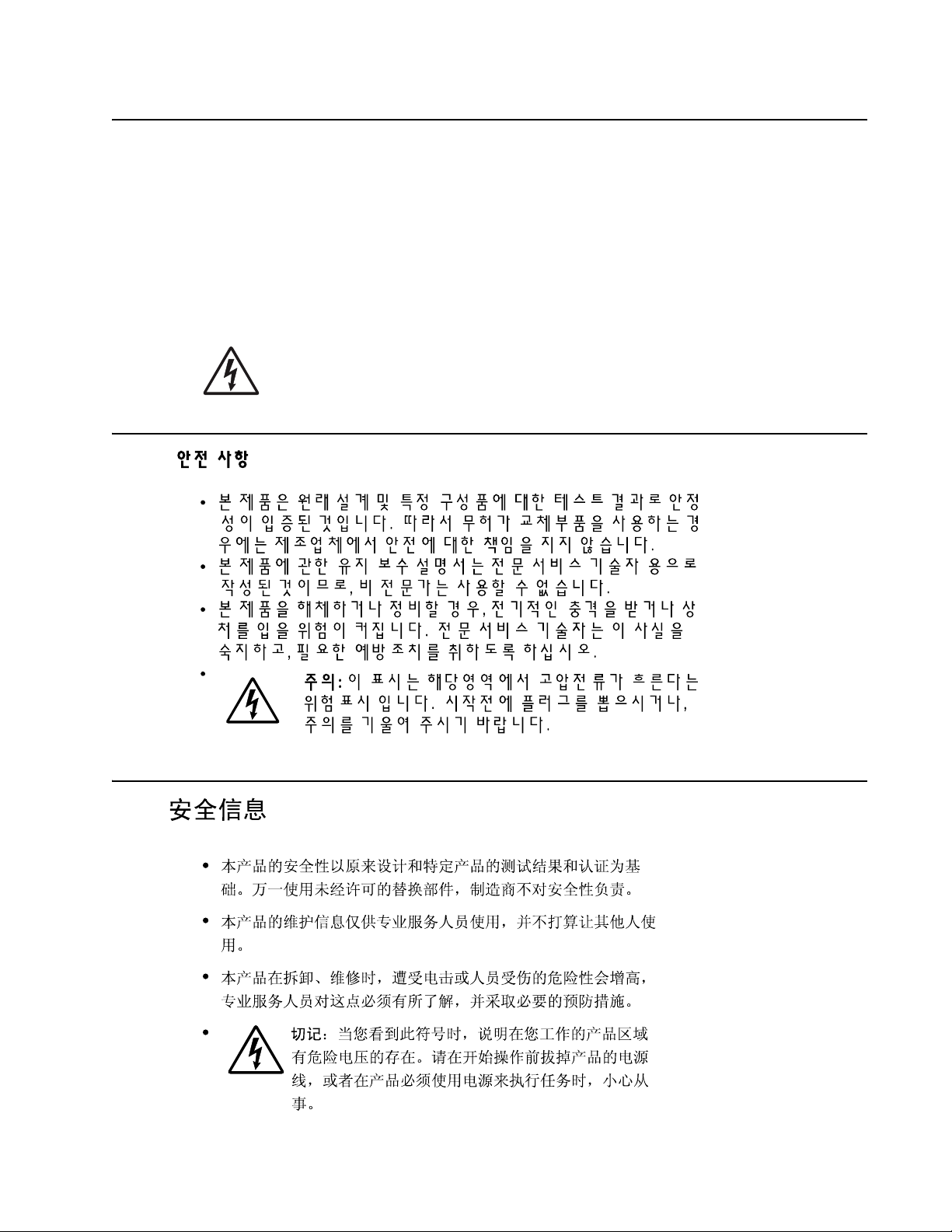
7002-xxx
Informació de Seguretat
• La seguretat d'aquest producte es basa en l'avaluació i aprovació del disseny original i els compon ents
específics .
El fabricant no es fa responsable de les qüestions de
seguretat si s'u ti litzen peces de recanvi no autoritzades.
• La informació pel ma nteniment d’aquest producte està orientada exclu sivament a professionals i no està
destinada
a ningú que no ho sigui.
• El risc de xoc elèctric i de danys personals pot augmentar durant el procés de desmuntatge i de servei
d’aquest producte. El personal professional ha d’estar-ne assabentat i prendre
les mesures con venients.
• PRECAUCIÓ: aquest símbol indica que el voltatge de la part de l'equip amb la qual esteu
treballan t és perill ós. Abans de començ ar, desendol leu l' equip oextremeu les precauc ions si, per
treballar am b l'equip, l'heu de connectar .
-xix
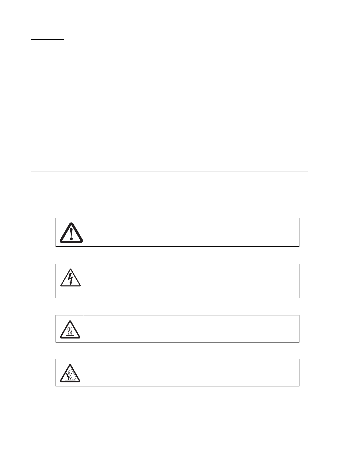
7002-xxx
Preface
This manual contains maintenance procedures for service personnel. It is divided into the following chapters:
1. General info r m a ti o n contains a general description of the printer and the maintenance approach used to
repair it. Speci al tools and test equipment, as well as general environmenta l and safety instructions, are
discussed.
2. Diagnostic information con tai ns an error indicator tab le, sym ptom tables, and service checks used to
isolate failing field replaceable units (FRUs).
3. Diagnostic aids contains tests and checks used to locate or repeat symptoms of printer pro blems.
4. Repair infor m a t io n provides instructions for maki ng printer adjustments and removing and installi ng
FRUs.
5. Connector locations uses illustr ations to identify the connector locations and test points on the printer.
6. Preventive maintenance contai ns the lubrication specifications and recomme ndations to prevent
problems.
7. Parts catalog contains illustrations and part numb ers for individual FRUs.
Appendix A contains service tips and information.
Conventions
Note: A note provides additional information.
Warning: A warning identi fi es something that might damag e the pr oduct hardware or software.
There are several types of caution statements:
CAUTION
A caution identifies something that might cause a servicer harm.
CAUTION
This type of caution i ndicates there is a danger from haz ardous voltage in the area of the
product where you are working. Unplug the product before you begin, or use caution if the
product must recei ve power in order to perform the task.
CAUTION
This type of caution i ndicates a hot surface.
-xx Service Manual
CAUTION
This type of caution i ndicates a tipping hazard.

7002-xxx
1. General information
The Lexmark™ X642e, X644e, and X646e are All-In-One laser MFPs th at provide print, copy, scan, and fax
functions designed to attach to IBM-compati ble personal computers and most computer networks . The operator
panel is touch-sensitive and allows the user to adj ust the viewing angle.
The Lexmark X64xe laser MFPs are available in the following models:
Model name Configuration Machine type
Lexmark X644e Network 7002-001
Lexmark X642e Network 7002-003
Lexmark X642e Network, modem 7002-005
Lexmark X644e Network, modem 7002-011
Lexmark X646e Network, hard disk 7002-101
Lexmark X646e Network, modem, hard disk 7002-111
Lexmark X644e HV, network 7002-002
Lexmark X642e HV, network 7002-004
Lexmark X642e HV, network, modem 7002-006
Lexmark X644e HV, network, modem 7002-012
Lexmark X646e HV, network, hard disk 7002-102
Lexmark X646e HV, network, hard disk 7002-112
Maintenance approach
The diagnostic information in this manual leads you to the correct field replaceable unit (FRU) or part. Use the
service erro r codes, user status message s, user error messages, service checks, and diagnostic aids to
determine the MPF probl em and repair the failure. Aft er you complete the repair, per for m tests as needed to
verify the repair. See “Start” on page 2-1.
General information 1-1
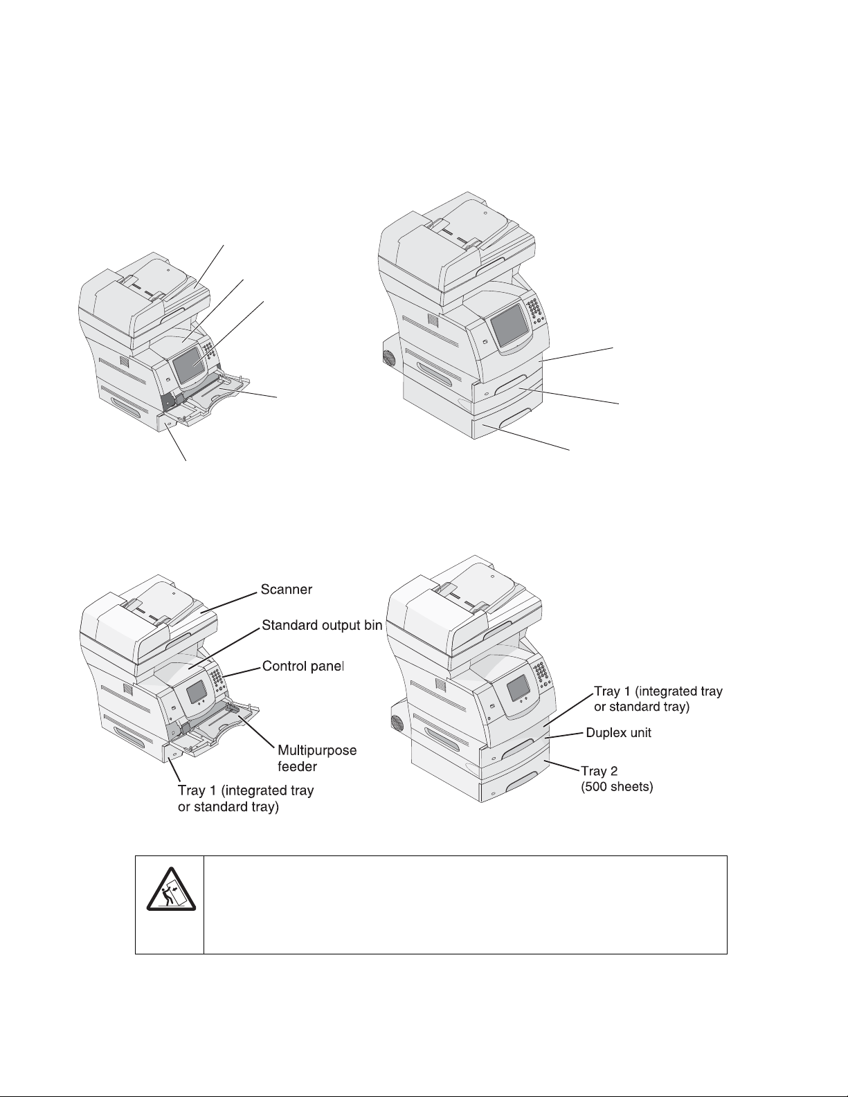
7002-xxx
n
Configured models
The following il lustrations show and compare st andard X642e and X644e MFPs and X642e and X644e MFPs
configured with a dupl ex unit and a 500-sheet drawer. Oth er pr int media handling options are also available.
Model X644e or X646e MFP
Standard
Scanner
Standard output bi
Control panel
Multipurpose
feeder
Tray 1 (integrated tray
or standard tray)
Model X642e MFP
Standard
Model X644e or X646e MFP
With duplex and drawer
Tray 1 (integrated tray
or standard tray)
Duplex unit
Tray 2
(500 sheets)
Model X642e MFP
With duplex and drawer
1-2 Service Manual
CAUTION
Floor-mounted configurations requir e additional furniture for stability. You must use ei ther a
printer stand or printer base if you a re using a 200 0-sheet dra wer. Certain ot her confi gurations
also must have a print er st and or printer base. More info rmation is available on our Lexm ark
Web site at www.lexmark.com/multifunctionprinters.

7002-xxx
Options
The following opt ions a re avail able. Some options are n ot avai l able i n ever y c ountry or r egion. Contact y our poi nt
of purchase for options available in your country or region.
• Memory options of 128MB, 256MB, and 512MB SDRAM
• Flash memory option s of 32MB and 64M B
• Hard disk—20GB+ with adapt er (model X646e only)
• Integrated network options
– Token-Ring
– Ethernet
– External serial adapter
– IPDS card assembly and SCS/TNe
– PRESCRIBE card assembly
– Bar code card asse mb ly
– Parallel interface card
– MarkNet™ Prof essional Print Server s— O nly one active internal networking connection is supported.
Installing an optional Lexmark MarkNet Prof essional N800 Series inter nal print server makes the
server the active network connection and disables the standard Etherne t port.
– Lexmark PrintCryption™ card
– Forms card (single-byte and Simplified Chinese)
• Media handling oper ations
– 250- and 500-sh eet paper trays of A4, letter, A5, B5, Execu ti ve, folio, statement , and l egal size
– 250- and 400-sh eet uni versally adjustable trays
– 250- and 500-sh eet paper drawers
– 400-sheet universally adjustable tr ay
– 2000-sheet high-capacity feeder—always used below any other drawer.
– Envelope feeder
– Duplex opti on—500- sheet ( For Lex mark X644e and Lexm ark X6 46e with int egrate d 500 -sheet output
tray)
• Application solutions
– Bar code card
– Lexmark Forms Card Software
– IPDS
– PRESCRIBE emulation card
– PrintCryption
• DBCS font cards
– Simplifi ed Chinese
– Traditional Chinese
– Japanese
– Korean
General information 1-3
7002-xxx
Specifications
General
MFP specifications
Lexmark X642e Lexmark X644e/X646e
Scanner
Scanner type Color flatbed scanner with ADF Color flatbed scanner with ADF
Scanner technology Charge coupled device (CCD) Charge coupled device (CCD)
Light sources Two Cold Cathode Fluorescent Lamp
(CCFL) and one CCD module per
scanner
Max optical resolution 600 x 600 dpi maximum (mono)
600 x 300 dpi (color) with final
resolution 300 x 300 dpi
Scan area (flatbed) 8.5 in. x 14 in. (216 mm x 355.6 mm)
maximum
Scanner ADF
Two CCFL and two CCD modules per
scanner
600 x 600 dpi maximum (mono)
600 x 300 dpi (color) with final
resolution 300 x 300 dpi
8.5 in. x 14 in. (216 mm x 355.6 mm)
maximum
ADF type Simplex ADF with C-path Single pass duplex ADF with C-path
ADF optical resolution 600 x 600 dpi maximum 600 x 600 dpi maximum
Document capacity 50 sheets (assuming 20 lb./ 75 g/m
Media thi c kness 0.05 mm ( m inim u m ) t o 0.15 mm
Media weight 15 lb (56 g/m
ADF scan area 8.5 in. x 14.0 in. (216 mm x 355 mm) 8.5 in. x 14.0 in. (216 mm x 355 mm)
Printer
Print technology Hot roll fuser Hot roll fuser
Fax
Modem (in models with
modem)
Resolution
• 1200 x 1200 dpi
• 2400 Image Quality
• 1200 Image Quality
• 600 x 600 dpi
2
) 50 sheets (assuming 20 lb./75 g/m2)
(maximum)
2
) to 32 lb (120 g/m2) 15 lb (56 g/m2) to 32 lb (120 g/m2)
Built-in Group 3 compatible, full
function fax 33,600 bps, Max V.34 half
duplex
0.05 mm (minimum) to 0.15 mm
(maximum)
Built-in Group 3 compati ble, full
function fax 33,600 bps, Max V.34 half
duplex
Data streams
• PostScript 3 emulation
• PCL 6 emulation
• PPDS migration tool
• PDF v1.5 emulation
1-4 Service Manual
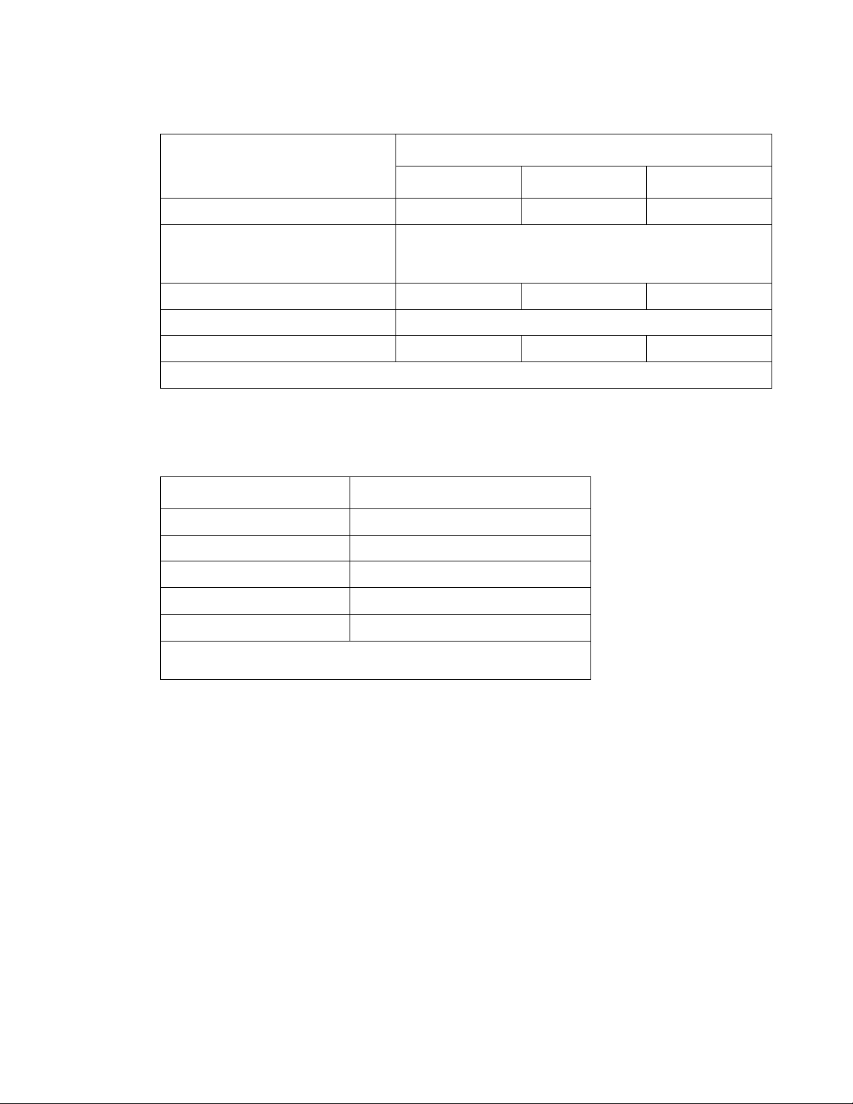
7002-xxx
Memory configuration
Models
Memory type
Lexmark X642e Lexmark X644e Lexmark X646e
Standard DRAM (MB) 128 256 256
Optional memory (MB)
(One slot—100 pin DDR SDRAM
unbuffered DIMMs)
Maximum (MB) 640 768 768
Optional flash memory (MB) 32 and 64 available
Hard disk N/A N/A <20GB
Note: One firmware card and one flash memory card are supported. Either slot supports both card types.
Depending upon the options and features used, additional memory may be required to opt imi ze performance.
Recommended operating clearances
Dimension Measurement
Left 12 in. (30.5 cm)
Right 8 in. (20.3 cm)
Front 20 in. (50.8 cm)
Rear 8 in. (20.3 cm)
Top* 12 in. (30.5 cm)
128, 256, and 512 available
* Allow clearance abo ve the pr inter front door clearance and for adding
options, such as additional input drawers.
General information 1-5

7002-xxx
Dimensions
Description Height Width Depth Weight
Printer
Lexmark X642e 28.0 in.
Lexmark X644e 28.0 in.
Lexmark X646e 28.0 in.
Lexmark X646e (with duplex and
500-sheet opti on)
Options
Duplex 500-page option 2.0 in.
250-Sheet drawer 3.5 in.
500-Sheet drawer 5.2 in.
2,000-Sheet drawer 15.0 in.
Envelope option (closed position) * * 7.72 in.
Envelope option (support fully
extended)
(710 mm)
(710 mm)
(710 mm)
35.0 in.
(890 mm)
(51 mm)
(90 mm)
(134 mm)
(381 mm)
* * 12.28 in.
22.0 in.
(560 mm)
22.0 in.
(560 mm)
22.0 in.
(560 mm)
22.0 in.
(560 mm)
15.7 in.
(398 mm)
15.7 in.
(398 mm)
15.7 in.
(398 mm)
15.7 in.
(398 mm)
25.4 in.
(645 mm)
25.4 in.
(645 mm)
25.4 in.
(645 mm)
26.0 in.
(660 mm)
24.1 in.
(595 mm)
18.0 in.
(457 mm)
19.0 in.
(520 mm)
18.0 in.
(457 mm)
(196 mm)
(312 mm)
80.0 lb
(34.9 kg)
83.0 lb
(37.7 kg)
84.5 lb
(46.7 kg)
103 lb
(46.7 kg)
11.3 lb
(5.1 kg)
6 lb
(2.7 kg)
7 lb
(3.2 kg)
31 lb
(14.1 kg)
4 lb
(1.8 kg)
4 lb
(1.8 kg)
MFP Stand with Cabinet 31.5 in.
(800 mm)
Low Profile MFP Stand 22.8 in.
(579 mm)
MFP Stand without Cabinet 31.5 in.
(800 mm)
Stability Enhanced Caster Base 6.0 in.
(152 mm)
10 Inch Cabinet Option 10.0 in.
(255 mm)
* Envelope option fit s wit hin height and width of printer .
22.4 in.
(569 mm)
22.4 in.
(569 mm)
22.4 in.
(569 mm)
27 in.
(685 mm)
15.7 in.
(397.6 mm)
24.5 in.
(622 mm)
24.5 in.
(594 mm)
24.5 in.
(622 mm)
27.0 in.
(686 mm)
17.54 in.
(445.7 mm
64 lb
(29.0 kg)
45 lb
(20.4 kg)
64 lb
(28.1 kg)
25 lb
(11.3 kg)
17.1 lb.
(7.8 kg)
1-6 Service Manual

7002-xxx
Power requirements
Average nominal power requirements for the base printer configuration (110 volt). Power levels are shown in
watts (W). Maximum current is given in Amperes (A).
Printing states Lexmark X642e Lexmark X644e Lexmark X646e
Off 0 W .05 W .05 W
Idle—average power
Power Saver on 30 W 20 W 20 W
Power Saver off 105 W 90 W 95 W
Continuous copying 650 W 875 W 875 W
Continuous printing 800 W 675 W 830 W
Printing—maximum current
100 V 12.3 A 7.8 A 8. 9 A
120 V 10.5 A 7.2 A 8. 0 A
230 V 5.4 A 3.4 A 4.1 A
Electrical specifications
Low voltage model
100 to 127 V ac at 50 to 60 Hz nominal
•
• 90 to 137 V ac, extreme
High voltage model
•
220 to 240 V ac at 50 to 60 Hz nominal (not available in all countries or re gions)
• 198 to 259 V ac, extreme
Notes:
• Using a power convert er or inverter is not recommended.
• All models are ENERGY STAR qualified.
• All models ship with Power Save Mode on.
• The default timeout to power saver is 30 minutes for models X644e/X646e and 45 minutes for model
X642e.
General information 1-7

7002-xxx
Environment
Printer temperature and humidity
• Operating
– Temperature: 16 to 32° C (60° to 90° F)
– Relative humidity: 8 to 80%
– Altitude: 10,000 ft. (0 to 3,048 meters)
• Storage and shipping environment (packaged)
– Temperature: -40° to 43° C (-40° to 110° F)
– Relative humidity: 5% to 95%
– Altitude: equivalent to 10,300 meters (0 to 34, 000 feet)
• Storage envir onm ent (unpacked)
– Temperature: 0° to 40° C (32° to 104° F)
– Relative humidity: 5% to 80%
Acoustics
All measurements are made in accordance with ISO 7779 and conform with ISO 9296.
Emission sound pressure level (d BA)
Mode
Bystander position
average (LpAm)
Printing
Copying
Scanning
Ready
Note: Measurement s apply to 300 dpi, 600 dpi, and 1200 dpi printing.
56 N/A 7.0
57 62 7.2
52 59 6.8
30 N/A 4.5
Standing Operator
Position (LpAm)
Declared sound
power level (Bels)
(LpAm)
1-8 Service Manual
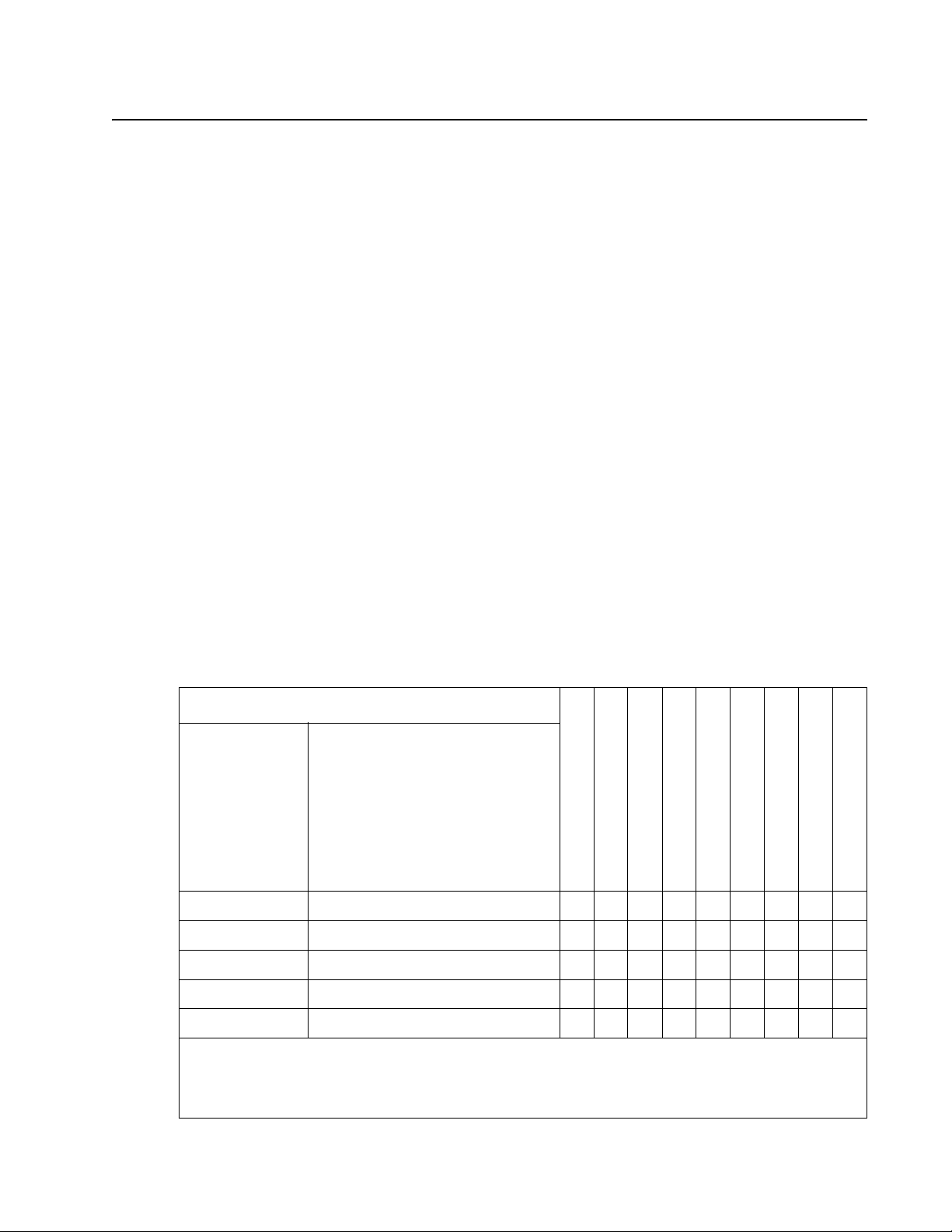
7002-xxx
Media specifications
Paper and specialty media guidelines
Print media is paper, card stock, transparencies, labels, and envel opes. This printer provi des high quality
printing on a variety of print media. You must consider a number of things concerning pri nt media before you
print, including:
• Supported prin t media
• Selecting print me dia
• Storing print media
• Avoiding jams
For more details about the types of paper and specialty media your printer supp ort s, refer to the Card Stock &
Label Guide available on our Lexmark Web site at www.lexmark.com.
We recommend that you try a li m ited sample of any paper or specialty media you are considering using with t he
printer before purchasing large quanti ti es.
Supported pr int media
The following tabl es provide information on st andard and optional sources for both input and output trays and
bins.
• Print media sizes
• Print media weights
• Media weights suppor ted in optional output bins
Note: If you use a print media size not list ed, select the next larger size.
Print media sizes
Legend ✓ — indicates support
Print media
size
A4 210 x 297 mm (8.27 x 11.7 in.) ✓✓✓✓✓✓ ✓✓
A5 148 x 210 mm (5.83 x 8.27 in.) ✓✓✓✓✓✓ ✓✓
JIS B5 182 x 257 mm (7.17 x 10.1 in.) ✓✓✓✓✓✓ ✓✓
Letter 215. 9 x 279.4 mm (8.5 x 11 in.) ✓✓✓✓✓✓ ✓✓
Dimensions
250-sheet tray
500-sheet tray
250 UAT
400 UAT
Multipurpose feeder
2000-sheet drawer (option)
Envelope feeder (option)
Duplex unit (option)
Standard output bin
Legal 215.9 x 355.6 mm (8.5 x 14 in.) ✓✓✓✓✓✓ ✓✓
1
This size does not appea r in the Paper Size menu until Tray Size Sensing is turned off. Refer to the User
Guide for more information.
2
This size setting formats the page for 215.9 x 355.6 mm (8.5 x 14 in.) unless the size is speci fied by the
software application.
General information 1-9

7002-xxx
Legend ✓ — indicates support
Print media
size
Dimensions
250-sheet tray
500-sheet tray
250 UAT
400 UAT
Multipurpose fe eder
2000-sheet drawer (option)
Envelope feeder (option)
Duplex unit (option)
Standard output bin
Executive 184.2 x 266.7 mm (7.25 x 10.5 in.) ✓✓✓✓✓✓ ✓✓
1
Folio
Statement
Universal
1
2
216 x 330 mm (8.5 x 13 in.) ✓✓✓✓✓✓ ✓✓
139.7 x 215.9 mm (5.5 x 8.5 in.) ✓✓✓✓✓ ✓
139.7 x 210 mm to 215.9 x 355.6
✓✓✓✓✓ ✓
mm
(5.5 x 8.27 in. to 8.5 x 14 in.)
69.85 x 127 mm to 215.9 x 355.6
✓✓
mm
(2.75 x 5 in. to 8.5 x 14 in.)
148 x 182 mm to 215.9 x 355.6 mm
✓
(5.83 x 7.17 in. to 8.5 x 14 in.)
76.2 x 127 mm to 215.9 x 355.6 mm
✓
(3 x 5 in. to 8.5 x 14 in.)
76.2 x 177.8 mm to 215.9 x 355.6
✓
mm
(3 x 7 in. to 9.01 x 14 in.)
7 ¾ Envelope 98.4 x 190.5 mm (3.875 x 7.5 in.) ✓✓✓
9 Envelope 98. 4 x 225.4 mm (3.875 x 8.87 in.) ✓✓✓
10 Envelope 104.8 x 241.3 mm (4.12 x 9.5 in.) ✓✓✓
DL Envelope 110 x 220 mm (4.33 x 8.66 in.) ✓✓✓
B5 Envelope 176 x 250 mm (6.93 x 9.84 in.) ✓✓✓
C5 Envelope 162 x 229 mm (6.38 x 9.01 in.) ✓✓✓
Other Envelope
1
98.4 x 162 mm to 176 x 250 mm
✓✓✓
(3.87 x 6.38 in. to 6.93 x 9.8 4 in. )
1
This size does not appea r in the Paper Size menu until Tray Size Sensing is turned off. Refer to the User
Guide for more information.
2
This size setting formats the page for 215.9 x 355.6 mm (8.5 x 14 in.) unless the size is speci fied by the
software application.
1-10 Service Manual

7002-xxx
Print media types
Print media
Paper ✓✓✓✓ ✓ ✓
Card stock ✓✓✓ ✓
Transparencies ✓✓✓ ✓
Vinyl labels
Paper labels
*
*
Polyester label
Dual-web and integrated labels* ✓✓✓ ✓
*
Printing label app lications on the MFP requires a special label fuser cleaner. The label fuser cleaner is
included with a special label cartridge for label applications.
Print media weights
Print media Type
Paper Xerographic
250-sheet drawer
500-sheet drawer
Multipurpose feeder
2000-sheet drawer
Duplex unit
Output bin
✓✓✓ ✓
✓✓✓ ✓
*
✓✓✓ ✓
Print media weight
Multipurpose
feeder and optional
250-sheet drawer
60 to 135 g/m2
grain long
(16 to 36 lb bond)
Envelope
feeder
n/a
or business
paper
Integrated tray and
optional
500-sheet drawer
60 to 176 g/m
2
grain long
(16 to 47 lb bond)
Card stock—
maximum (grain
1
long)
Card stock—
maximum (grain
1
short)
Index Bristol 163 g/m2 (90 lb) 120 g/m2 (67 lb)
Tag 163 g/m
Cover 176 g/m
Index Bristol 199 g/m
Tag 203 g/m
Cover 216 g/m
2
(100 lb) 120 g/m2 (74 lb)
2
(65 lb) 135 g/m2 (50 lb)
2
(110 lb) 163 g/m
2
(125 lb) 163 g/m2 (100 lb)
2
(80 lb) 176 g/m2 (65 lb)
Transparencie s Laser printer 138 to 146 g/m
(37 to 39 lb bond)
2
(90 lb) n/a
2
138 to 146 g/m
2
(37 to 39 lb bond)
General information 1-11

7002-xxx
Print media weight
Print media Type
Labels—
maximum
4
Paper 180 g/m
Integrated tray and
optional
500-sheet drawer
2
(48 lb bond)
Multipurpose
feeder and optional
250-sheet drawer
163 g/m
2
(43 lb bond)
Envelope
feeder
n/a
Note: Not supported
in the multipurpose
feeder.
Dual-web
paper
180 g/m
2
(48 lb bond)
163 g/m
(43 lb bond)
2
Note: Not supported
in the multipurpose
feeder.
Polyester 220 g/m
(59 lb bond)
2
220 g/m
(59 lb bond)
2
Note: Not supported
in the multipurpose
feeder.
Vinyl
5
300 g/m
(92 lb liner)
2
260 g/m
2
(78 lb liner)
Note: Not supported
in the multipurpose
feeder.
Integ ra ted forms Pressu re-
140 to 175 g/m
2
140 to 175 g/m
2
sensitive area
(must enter
the MFP firs t)
Envelopes
100% cotton
content maximum
weight—24 lb
Paper base
(grain long)
Sulfite, woodfree, or up to
100% cotton
bonds
75 to 135 g/m
(20 to 36 lb bond)
2
75 to 135 g/m
(20 to 36 lb bond)
Not recommended 60 to 105 g/m
(16 to 28 lb bond)
2
2
2, 3
60 to 105 g/m
(16 to 28 lb
3
bond)
2
Note: 28 lb envelopes are li m ited to 25%
cotton content.
1
Grain short is preferred for papers over 135 g/m2.
2
Includes envel opes fed from the multipurpose f eeder only.
3
28 lb bond envelopes are limited to 25% cotton content.
4
Printing label app li cations on the MFP requires a special label fuser cleaner.
5
Information on whether your vinyl label convert er has passed Lexmark criteria is avai lable at the Lexmark
Web site (www.lexmark.com); search for “converter list.” You can also check the Lexmark Automated Fax
system (LEXFAX
SM
).
1-12 Service Manual

7002-xxx
Selecting print media
Selecting the appropriate print media for the MFP helps you avoid printing problems. The following sections
contain guidelines for choosing the correct print media for the MFP.
• Paper
• Transparencies
• Envelopes
• Labels
• Card stock
Paper
For the best print qual ity, use 75 g/m2 (20 lb) xerographic, grain long paper. Try a sample of any paper you are
considering using with the MFP before buying large quantities.
When loading paper, note the recommended print sid e on the paper package, and load paper accordingly.
Paper characteristics
The following paper characteristics affect print quality and reliability. We recommend that you follow these
guidelines when evaluating new paper stock.
For detailed information, see the Card Stock & Label Guide located on the Lexmark Web site at
www.lexmark.com.
The laser printing process heats paper to high tem peratures of 230°C (446°F). For Magnetic Ink Character
Recognition (MICR) applications and for non-MICR appl ications, use only paper able to withstand these
temperatures without discoloring, bleeding, or releasing hazardous emissions. Check with the manufacturer or
vendor to determi ne whether the paper you have chosen is acceptable for laser printers.
Weight
The MFP can automatical ly feed paper weights from 60 to 176 g/m
integrate d and opti onal 500-sheet trays and paper weights from 60 to 135 g/m
the multipurpose feeder and optional 250-sheet trays. Paper lighter than 60g/m
enough to feed properly, causing jams. For b est performance, use 75 g/m
using paper narr ower t han 182 x 257 m m (7.2 x 10.1 in.), make sure the weight is greater than or equal to
2
90 g/m
Unacceptable paper
The following papers are not recommended for use with the MFP:
(24 lb bond).
2
(16 to 47 lb bond) grain long in the
2
(16 to 36 lb bond) grain long in
2
(16 lb) might not be stiff
2
(20 lb bond) grain long paper. When
• Some chemically treated papers used to make copies wi thout carbon paper, also known as car bonless
papers, carbonless copy paper (CCP), or no carbon required (NCR) paper (see the Card Stock & Label
Guide located on the Lexmark Web site at www.lexmark.com for supported chemically treated papers)
• Preprinted papers with chemicals that may contaminate the MFP
• Preprinted pap ers that can be affected by the temperature in the MFP fuser
• Preprinted p apers that require a registration (the precise print l ocation on the page) greater than ±0.09 in.,
such as optical character recognition (OCR) form s
• In some cases, you can adjust registration with your software appli cation to successf ully print on these
forms.
• Coated papers (era sable bond), synthetic papers, thermal papers
• Rough-edged, rough or heavily textured surface papers or curled papers
• Recycled papers containing more than 25% post-consumer waste that do not meet DIN 19 309
• Recycled paper havi ng a weight less than 60 g/m
2
(16 lb)
• Multiple-part forms or documents
General information 1-13

7002-xxx
Transparencies
The MFP can print directl y on transparencies designed for use in laser printers. Print quality and durabili ty
depend on the transparency used. Always print samples on the transparencies you are considering before
buying large quantities.
The Paper Type setti ng should be set to Transparency to hel p prevent jams. In Macintosh, be sure t o set the
Paper Type to Transpar ency in the Print dialog on the Imagin g choi ce in the Copies & Pages pop-up menu.
Use transparencies designed s pecifically for laser printers. Check with the manufacturer or vendor to determine
whether your transparencies are compatible with laser printers that heat transparencies to 230°C (446°F). Use
only transparencies that are able to withstand these temperatures without melting, discoloring, offsetting, or
releasing hazardous emissions. For detailed information, see the Card Stock & Label Guide, which is available
on the Lexmark Web site at www.lexmark.com.
Transparencies can be fed automaticall y from the multipurpose feeder and all standard and optional trays,
except the 2000-sheet drawer. Before loading transparencies, fan the stack to prevent sheets from sticking
together.
Be careful when you handle transparencies. Fingerprints on the surface of the transparency cause poor print
quality.
Envelopes
You can load up to 10 envelopes in the multipurpose feeder and 85 envelopes in the envelope feeder. Try a
sample of any envelopes you are considering using with the MFP before buying large quantities.
When printing on envelopes:
• To achieve t he b est poss ib le pr int qu alit y, use only h ig h-quali ty e nvelopes t hat are des igned f or use i n laser
printers.
• Set the Paper Size/Type in the Paper menu to MP Feeder, Manual Env, or Env Feeder depending on the
source you are using . Set the paper type to Envelope, and select the correct envelope si ze from the
operator panel , t he MFP driver, or from MarkVision™ Profession al.
• For best perf ormance, use envelopes made from 75 g/m
(28 lb bond) weight for the mul tipurpose feede r or 105 g/m
long as the cotton content is 25% or less. Envelopes with 100% cotton content must not exceed 90 g/m
(24 lb bond) weight.
2
(20 lb bond) paper. You can use up to 105 g/m2
2
(28 lb bond) weight for the en velope feeder as
• Use only new, undamaged envelopes.
• For best performa nce and to minimize jams, do not use envelopes that:
– Have excessive curl or twist.
– Are stuck together or damaged in any way.
– Contain windows, holes, perforations, cutouts or embossing.
– Use metal clasps, string ties, or metal folding bars.
– Have an interlocking design.
– Have postage st am ps att ached.
– Have any exposed adhesive when the flap is in the sealed or clos ed position.
– Have nicked edges or bent corners.
– Have rough, cockle, or laid finishes.
• Use envelopes that can withstand temperatures of 230°C (446°F) without sealing, excessive curling,
wrinkling, or r eleasing hazardous emiss ions. If you have any doubts about the envelopes you are
considerin g using, check with the envelope supplier.
• Load only one size of env elope at a time in the envelope feeder.
• A combination of high hum idity (over 60%) and the high printing temperatures may seal the envelopes.
2
1-14 Service Manual

7002-xxx
Labels
The MFP can print on many label s designed for use with laser print ers. These labels are supplied in letter size,
A4 size, and legal size sheets. Label adhesives, face sheet (printab le st ock), and topcoats must be able to
withstand tempe ratures of 230°C (446°F) and pres sure of 25 pounds per square inch (psi).
Try a sample of any labels you are considering using wit h the MFP before purchasing a large quant ity.
For detailed information on label printing, characteristics, and design, see the Card Stock & Label Guide
available on the Lexmark Web site at www.lexmark.com/publications.
Note: Labels are one of the most difficul t print media for laser MFPs. All MFP model s require a special fuser
cleaner for label applications to optimize feed reliability.
After printi ng approximately 10,000 pages of l abels (or each time you replace the print cartridge), comp lete the
following steps to maintain MFP feeding reliability:
1. Print five sheets of paper.
2. Wait approximately five seconds.
3. Prin t five more sheets of paper.
When printing on labels:
• Set the Paper Size/Type menu item to Labels i n the Paper menu. You can set the Paper Size/Type from the
MFP operator panel, the MFP driver, or from MarkVision Prof essional.
• Feed vinyl l abels from the st andard 250- or 500-sheet trays or the optional 250- or 500-sheet drawe rs. For
vinyl labels, set the Paper Type to Labels, the Labels Texture to Smooth, and the Label Weight to Heavy, or
set the Paper Type to vinyl labels and the texture and weight to normal.
• Do not load labels with paper or transparencies in the same source; mixing print media can cause feeding
problems and print quality problems.
• Do not use label sheets with a slick backing material.
• Use full label sheet s. Partial sheets may cause lab els to peel off during printing, resulting in a jam. Partia l
sheets also cont am inate the MFP and your cartridge with adhesive, and could void the MFP and cartridge
warranties.
• Use labels t hat can withstand temperatures of 230°C (4 46° F) without sealing, excessive curling, wrinkling,
or releasing hazardous emissions.
• Do not print within 1 mm (0.04 in. ) of the edge of the label, of the perforations, or between die-cuts of the
label.
• Do not use label sheets that have adhesive to the edge of the shee t. We recommend zone coating of the
adhesive at leas t 1 mm (0.04 i n.) away from edges. Adhesive material contaminates the MFP and could
void the warranty.
• If zone coating of the adhesive is not possible , a 1.6 mm (0. 1 in. ) strip should be removed on the leading
and driver edge, and a non-oozing adhesive should be used.
• Remove a 1.6 mm (0.1 in.) stri p from the leading edge to prevent labels from peeling inside th e MFP.
• Portrait ori entation is preferred, especially when printing bar codes.
• Do not use labels that have exposed adhesive.
General information 1-15

7002-xxx
Card stock
Card stock is single ply , and has a large array of properti es, such as the moisture cont ent, thickness , and texture,
that can signifi cantly affect print quality. See “Supported print media” on page 1-9 for information on the
preferred weight and for the grain direction of print media.
Try a sample of any card st ock you are considering using wit h the MFP before purchasing a large quantity.
After printi ng approximately 10,000 pages of card stock (or each time you r eplace the print cartridge), complete
the following st eps to maintain MFP feeding reliability:
1. Print five sheets of paper.
2. Wait approximately five seconds.
3. Prin t five more sheets of paper.
When printing on car d stock:
• Set the Paper Type menu item in the Paper menu to Card Stock from the operator panel, from th e MFP
driver, or from Mark Vision Professional.
• Be aware that preprint ing, per forat ion, and creasi ng can signi fica ntly affec t the pri nt qualit y and caus e print
media handling or jamm ing problems.
• Avoid using card stock that may release hazardous emissions when heated.
• Do not use preprinted card stock manufactured with chemi cals that may contaminate the M FP. Preprinting
introduces semi-liquid and volatil e com ponents into the MFP.
• We recommend the use of grain short card stock.
Storing print m edia
Use the following gui delines to avoid paper feedi ng problems and uneven print quali ty.
• Store paper in an environment where the temperature is approximately 21°C (70°F) and the relative
humidity is 40%.
• Store cartons of paper on a pallet or shelf rather than directly on the floor.
• If you store individu al packages of paper out of the original carton, make sure they rest on a flat surf ace so
the edges do not buckle or curl.
• Do not place anything on top of paper packages.
• Store paper in its original wrapper until you load i t in to t he MFP.
Avoidi ng j ams
Use appropriate print media (paper, transparencies, labels, and card stock) to help ensure trouble-free printing.
Note: Try a limited sample of any print media you are considering using with the MFP befor e purchasing large
quantities.
By selecting the appropriate print media and loadi ng it properly, you can avoid mos t ja ms .
The following hint s can help you avoid jams:
• Use only recommended print media.
• Do not overload th e print med ia sourc es. Mak e sure the st ack heig ht does not exceed the maximu m height
indicated by t he stack line on the labels in the sources.
• Do not load wrinkled, creased, damp, or curled print media.
• Flex, fan, and strai ghten print media before you l oad it. If jams do occur with print med ia, try feeding one
sheet at a time through the multipurpose feeder.
• Do not use print media that you have cut or trimmed yourself.
• Do not mix print media sizes, weights, or types in the same print media source.
• Make sure the recom m ended print side is loaded in the source according to your simplex or duplex needs .
1-16 Service Manual

7002-xxx
• Keep print media stored in an acceptable environment. See “Storing print media” on page 1-16.
• Do not remove trays dur ing a print job.
• Push all trays in firmly after loading them.
• Make sure the gui des i n the trays are p roperl y posit ioned f or the s ize of p rint media you hav e lo aded. Make
sure the guides are not pl aced too tightly against the st ack of print media.
• If a jam occurs, clear the entire media path.
Tools required
Flat-blade screwdrivers, various sizes
Phillips screwdrivers, various sizes
7/32 inch open-end wrench
7.0 mm nut driver
5.5 mm wrench
Needlenose pli ers
Diagonal side cutters
Spring hook
Feeler gauges
Analog or digital multimeter
Parallel wrap plug 1319128
Twinax/serial debug cable 1381963
Flash light (optional)
General information 1-17

7002-xxx
Acronyms
ADF Automatic Document Feeder
AIO All-In-One
CCD Charge Coupled Device (CCD)
CRU Customer Replaceable Unit
DIMM Dual Inline Memory Module
DRAM Dynamic Random Access Memory
EP Electrophotographic process
EPROM Erasable Programmable Read-Only Memory
ESD Electrostatic Discharge
FRU Field Replace able Unit
GB Gigabyte
HCIT High-Capacity Input Tray
HVPS High Voltage Power Supply
ITC Internal Tray Card
LASER Light Amplification by Stimulated Emission of Radiat ion
LCD Liquid Crystal Display
LED Li ght-Emitting Diode
LES Lexmark Embedded Solutio n (appl ications)
LVPS Low Voltage Power Supply
MDC M otor Driver Control
MFP Multifunction Print er
MPF Multipurpose Feede r
NVRAM Nonvolatile Random Access M em ory
OPT Optical Sensor
PC Photoconductor
PIN Personal Identification Number
PJL Printer Job Language
POR Power-On Reset
POST Power-On Self Test
PP Parts Packet
PWM Pulse Width Modulation
RIP Raster Imaging Proces sor
SCC Scanner Control Card
SDRAM Synchronous Dynamic Random Access Memory
SIMM Single Inline Memory Module
UAT Universally Adjustable Tray
USB Universal Serial Bus
V ac Volts alternating current
V dc Volts direct current
1-18 Service Manual

7002-xxx
2. Diagnostic information
Start
CAUTION
CAUTION
When you see this s ymbol, ther e is a danger from haz ardous voltage in the a rea of the produ ct
Remove the power cord from the pri nter or wall outlet before you connect or disconnect any
where you are working. Unplug the product before you begin, or use caution if the product
cable or electronic board or assembly for personal safety and to prevent damage to the printer.
must receive power in order to perform the task.
CAUTION
Use the handholds on the side of th e printer. Mak e sure your fingers are not under the pr inter
when you lift or set the printer down.
Use the service error code, user status message, user error message, symptom table, service checks, and
diagnostic aids in this chapter to determine t he corrective action necessary to repair a malfunctioning printer.
They will lead you to solutions or service chec ks, including use of various tests.
Sympto m tables
If your machine completes the does not display an error message, and you have a prob lem, go to “Symptom
tables” on page 2-10. Locate your symptom, and take the appropriate action. The following tables are
available:
Servi ce error s (8xx.xx and 9xx.xx’ s)
If a service error code appears while you are working on the machine, go to “Service error codes” on
page 2-13, and take the indicated action for that error.
Service error codes are indicated by a three-digit error code followed by a period and additional numbers in the
format XXX.YY. In most cases, five digits are shown.
User status and attendance messages
•
User status messages provide t he user with information on the current status of the printer. Ready displays
on the first line of the display unless invoked , and then Power Saver displays. If a user status message is
displayed, go to “User status displays.” on page 2-38.
• User attendance messages are indicated by a two or three-digit error code that pro vides the user with
information that explains a problem with a pr int cartridge, p aper jam, option, port, and so on. If a user error
message displays, go to “User attendance messages” on page 2-42 and “User attendance
messages—paper jams and paper handling errors (2xx.xx)” on page 2-57.
Additional information
“Understanding the MFP operator panel” on page 2-2
•
• “Menus” on page 2-9
• “Diagnostics Menu” on page 3-2
• “Configuration menu (CONFIG MENU)” on page 3-24
• “Theory” on page 3-36
• “Paper feed jams” on page 3-38
• “Parts catalog” on page 7-1
Diagnostic information 2-1

7002-xxx
Understanding the MFP operator panel
MFP and scanner setti ngs can be changed several ways: through the MFP operator panel, the sof tware
application in use, the print driver, MarkVision Professional, or th e Web pages. Settings changed from the
application or print driver apply only to the jo b being sent to the MFP.
Changes made to print, fax, copy, and e-mail settings from an application over ri de changes made from the
operator panel.
If a sett ing cann ot be cha nged from th e appl icat ion, use the MFP oper ator p anel, Mar kVisi on Prof ess ional, or t he
Web pages. Changing a setting from the MFP operator panel, MarkVision Professional, or the Web pages
makes that setti ng the user default.
MFP operator panels
Model X642e
2-2 Service Manual
Models X644e/X646e

7002-xxx
Callout Operator panel item Funct ion
1 LCD A liquid crystal display (LCD) whic h shows hom e screen buttons, menus, menu
2 Indicator ligh t Gives information about the status of the MFP using the colors red and green.
3 0–9
Note: Referred to as the
numeric keypad.
4 # (Pound or number
character)
5 Dial Pause Press to cause a two- or three-second dial pause in a fax number. The button only
6 Clear All When in the function menus, such as Copy, Fax, E-mail, and FTP, it returns all
7 Start Press to initiate the current job indicated on the operator panel.
8 Stop Press to cause the printi ng or scanning to stop.
0 Backspace Within the Copy menu, which is accessed by touching the Copy button, press
10 Asterisk (*) * is used as part of a fax number or as an alphanumeric character.
items, and values. Allows for making selections within Copy, Fax, and so on.
Status Indicates
Off MFP power is off.
Blinking green MFP is warming up, proce ssing data, or
printing a job.
Solid green MFP is on, but idle.
Solid red Operator intervention is required.
Press these buttons to e nter numbe rs wh en the LCD s creen has a fiel d that acc epts
the entry of numbers. Also, use these buttons to dial phone numbers for faxes.
Note: If a number is pressed while on the home screen without pressing the #
button first, the Copy menu opens and changes the Copy Quantity .
Press this button:
• For a shortcut identi fi er.
• Within phone numbers. For a Fax number with a #, enter it twice — ##.
• From the home screen, the Fax Destination List menu item, E-mail Destination
List menu item, or Profile Li st menu item to access shortcuts.
functions within the Fax menu or wi th f ax functions.
Press from the home screen to redi al a fax number.
When outside of the Fax menu, fax function, or home screen, pressing Dial Pause
causes an error beep.
When sending a fax, in the Fax To: field, a Dial Pause press is represent ed by a
comma (,).
settings to their default values, and then returns the MFP to the home screen.
When in any other menu while the MFP is Ready, it cancels all changes that have
not been submitted and returns the MFP to the home screen.
From the home screen, press it t o start a copy job with the default setti ngs.
If pressed while a job runs through the scanner, the button has no effect.
During a scan job, the scanner finishes scanning the current page and then stops,
which means paper may remain in the automatic document feeder (ADF).
During a print job, the pri nt media path is cleared before the pri nting stops.
Stopping appears on the operator panel during this process.
Backspace to del ete t he r ight -most di git of the value i n the Copy Co unt. Th e defaul t
value of 1 appears if the entire number is deleted by pressin g Backspace
numerous times.
Within the Fax Destinati on List, press Backspace to delete the rig ht-most digit of a
number entered manuall y. It also deletes an entire shortcut entry. Once an entire
line is deleted, another press of Backspace causes the cursor to move up one line.
Within the E-mail Destination List, press Backspace to delete the character to the
left of the cursor. If the entry is in a shortcut, the entire entry is deleted.
Diagnostic information 2-3

7002-xxx
Callout Operator panel item Function
11 USB Direct interface The host Universal Serial Bus (USB) direct inter face on the operator panel is used
12 Home
(only on model X642e)
13 Help Tips
(only on model X642e)
14 Menu
(only on model X642e)
15 Contrast icon
(only on model X642e)
to plug in a USB flash memory device and pr int any Portable Document Format
(PDF) [.pdf file], Joint Photographic Experts Group (JPEG) [.jpeg or .jpg file],
Tagged Image File Format (TIFF) [.tiff or .tif file], Graphics Inter change Format
(GIF) [.gif file] , Basi c M ultilingual Plane (BMP) [. bm p fi le], Portable Network
Graphics (PNG) [.png file] , Pi Cture eXchange (PCX) [.pcx file] , and PC Pain tbrush
File Format [.dcx file] files.
The USB direct interface can also be used to scan a document to a USB flash
memory device using the PDF, TIFF, or JPEG formats.
Returns the LCD to the home screen.
Accesses the context-sensitive Help feature.
Accesses the menus. These menus are only available when the MFP is in the
Ready state.
Identifies the location of the contrast wheel. Look on the left side of the MFP near
this icon to locate the contrast wheel which adjusts the contrast on the LCD.
Home screen and Home screen buttons
After the MFP is turned on and a short warm-up per iod occurs, the LCD shows the following basic screen whi ch
is referred to as the Home screen. Use the Home screen buttons t o initiate an action such as copy, fax, or scan,
to open the menu screen, or to respond to messages.
Buttons and touchscreen icon buttons
Buttons and touchscreen icon buttons (refer to Menus & Messages for comprehensive list)
Models X644e,
X646e
2-4 Service Manual
Model X642e Button name Function
Copy Touch to access the Copy menus.
Copy
If the home screen is shown, press a number to access the
Copy menus, too.

7002-xxx
Butt ons and touchs creen icon buttons (refer to Menus & Messages for comprehensive list) (continued)
Models X644e,
X646e
(Icon) (Button) Menus (A key is
(Icon) (Button) ? (Tips) Tips is a context-sensitive Help feature.
Model X642e Button name Function
E-mail
@
Ready.
Status/ Supplies
FTP
E-mail Touch to access the E-mail men us. It is possible to scan a
shown on the
button.)
Status message
bar
Status/Supplies Appears on the LCD whenever the MFP stat us includes a
FTP Touch to access the File Transfer Protocol (FTP) menus. A
document directly to an e-mail address.
Touch to access the men us. These menus are only available
when the MFP is in the Ready state.
For models X644e and X646e, the Menus icon is on a gray
bar called the navigation bar.
For model X642e, the Menu button is on t he lef t side of the
operator panel. See “Menu (only on model X642e)” on
page 2-4.
Shows the current MFP status such as Ready or Busy.
Shows MFP conditions such as Toner Low.
Shows intervent ion mess ages to gi ve instruct i ons on wha t the
user should do so the MFP can continue processing, such as
Close door or insert print cartridge.
message requiring intervention. Touch it to access the
messages screen for more information on the messag e
including how to clear it.
For models X644e and X646e, all menus have a Tips icon on
the touchscreen panel.
For model X642e, there is a Tips button on the operator
panel, below the touchscr een panel. See “Help Tips (only
on model X642e)” on page 2-4.
document can be scanned directly to an FTP site.
Fax Touch to access the Fax menus.
Fax
(Icon) (Button) Home For models X644e and X646e, touch the Home icon to return
Release Held
Release
Held Faxes
Faxes (or Held
Faxes if in
Manual Mode)
to the home screen. The Home icon appears o n ever y scree n
except the home screen.
For models X642e, press th e Home button on the operator
panel below the touchscreen to return to the home screen.
See “Home (only on model X642e)” on page 2-4.
There are held faxes with a sched uled hold time previously
set. To ac cess the list of held faxes, touch this button.
Diagnostic information 2-5

7002-xxx
Butt ons and touchs creen icon buttons (refer to Menus & Messages for comprehensive list) (continued)
Models X644e,
X646e
Model X642e Button name Function
Search Held
Jobs
Held Jobs To open a screen contai ning all the held jobs containers.
Held Jobs
Lock Device Models X644e and X646e—This button appears on the
Unlock Device Models X644e and X646e—This button appears on the
To search on any of the following items and return any
matches:
• User names for held or confidential print jobs
• Job names for held jobs, excluding confidential pri nt jobs
• Profile names
• Bookmark container or job names
• USB container or job names fo r supported extensions
only
screen when the MFP is unlocked and Device Lockout
Personal Identification Number (PIN) is not null or empty.
To lock the MFP:
1.Touch Lock De vi ce to open a PIN entry screen.
2.Enter the correct PIN to lock the operator panel which
locks both the operator panel buttons and the touchscreen buttons.
Once the operator panel is locked, the PIN entry screen
clears, and the Lock Device button is replaced with the
Unlock Device button.
Note: If an invalid PIN is entered, Invalid PIN. appears. A
pop-up screen appears with the Continue button. Touch
Continue. The home screen returns with the Lock Device
button.
screen when the MFP is locked. The operator panel buttons
and shortcuts cannot be used while it app ears and no default
copy starts may occur.
To unlock the MFP:
1.Touch Unlock Device to open a PIN entry scre en.
2.Enter the correct PIN to unlock the numeric keypad (0–9)
and the Backspace button on the operator panel.
Note: If an invalid PIN is entered, Invalid PIN. appears. A
pop-up screen appears with the Continue button. Touch
Continue. The home screen r eturns with the Unlock Device
button.
2-6 Service Manual

7002-xxx
Butt ons and touchs creen icon buttons (refer to Menus & Messages for comprehensive list) (continued)
Models X644e,
X646e
Cancel
Jobs
Scan the
ADF
Model X642e Button name Function
Cancel Jobs To open the Cancel Jobs screen. The Cancel Jobs screen
Cancel Jobs
shows any of the following items under t hree headings on the
screen which are Print, Fax, and Network:
•print job
Cancel
Job
• copy job
•fax
•profile
• FTP
• e-ma il s en d
Each heading has its own list of jobs shown in a column
under the headi ng. Eac h c olumn can onl y show th ree j obs per
screen. The job appears as a button. If more than three jobs
exist in a column, then the down arrow appears at the bottom
of the column. Each touch of the down arrow accesses one
job in the list. When more than three jobs exist, once the
fourth job in the list is reached, then an up arrow appears at
the top of the column.
Scan the ADF
Scan the flatbed
Model X644e and X646e—On the gray navigation bar, these
two choices indica te that two types of scanning are possible.
One may choose to scan from the ADF or the flatbed.
Scan the
flatbed
Submit
Back
Submit
Back
For models X644e and X646 e—To save the value as the n ew
user default setting, t ouch Submit. A green butt on i ndi cates a
choice. If a different value within a menu item is touched, it
needs to be saved to become the cur rent use r defaul t sett ing.
For model X642e—To save the value as the new user def ault
setting, touch Submit.
Back For all models, touch Back to return to the previ ous screen,
and all the settings for the scan job made on Sample screen
one are lost.
For models X644e and X646e, when the
Back button is shaped like this, no ot her
Back
navigation is possible from this screen
except to go back. If any other choice is
made on the navigation bar, the screen
closes.
For models X644e and X646e, when the
Back button is shap ed li ke this, both
Back
forward and backward nav igation is possible
from this screen, so there are other options
available on the screen besides selecting
Back.
Down arrow Touch the down arrow to mov e d own to t he n ext i tem i n a li st,
such as a list of menu ite ms or values . The d own arrow does
not appear on a screen with a short lis ti ng. It only appears if
the entire listing cannot be seen on one screen. On the last
screen of the listi ng, the down arrow is gr ay to indicat e th at it
is not active since the end of the list appears on this screen.
Diagnostic information 2-7

7002-xxx
Butt ons and touchs creen icon buttons (refer to Menus & Messages for comprehensive list) (continued)
Models X644e,
X646e
Continue
Model X642e Button name Function
Up arrow Touch the up arrow to move up to the next i tem in a li st, su ch
Unselected radio
button
Selected radio
button
Continue Touch Continue after a menu item or value on a screen is
Continue
Custom Allows for creating a custom button based on the user’s
Custom
as a list of menu items or values . When on the first screen
presented with a l ong lis t, the up arr ow is gray to in dicat e t hat
it is not activ e. On the s econd screen nee ded to show t he r est
of the listed item, the up arrow is blue to show that it is active.
This is an unselected radio button.
This is a selected radio button. Touch a radio button to se le ct
it. The radio button changes color to show it is selected. In
Sample screen two, the only paper size selected is Lett er.
selected and more changes need to be made for a job from
the original screen. Once Continue is touched, the ori ginal
screen appears.
needs.
Cancel
Done
Cancel
Done
Cancel Touch Cancel to cancel an action or a selection.
Touch to cancel out of a screen and return to the previous
screen.
Select Touch to select a menu. The next screen appears showing
menu items.
Touch to select a menu item. The next screen appears
showing values.
Done Allows specifying that a job is fin ished. For example, when
scanning an original document, one could indicate that the
last page is scanned, and then printing the job would begin.
Home Touch the Home button to return to the home scr een. The
Home button appears on every screen except the home
screen. See the “Home screen and Hom e screen butt ons”
on page 2-4 for more informati o n .
2-8 Service Manual

7002-xxx
Menus
A number of me nus are availabl e to make it easy for you to chang e M FP settings or pr int reports. To access the
menus and settings:
• Models X644e/X646e—touch the menu icon in the lower right corner of the home screen
• Models X642e—pres s the menu button ( ) to the left of the operator panel.
When a value or setting is selected and saved, it is stored in MFP memory. Once stored, these settings remain
active until new ones are stored or the factory defaults are restored.
Note: Settings chosen for faxin g, scanning, e-mailing, copying, and settings for printing from the applicati on
may override the set tings selected from the oper ator panel.
The following diagr am shows the touch screen menu index and th e men us and it em s available under each
menu. For more infor ma ti on about menus and menu items, see the Menu s and M essages Guide on the
Software and Document ati onCD.
Paper Menu
Default Source
Paper Size/Type
Configure MP
Envelope Enhance
Substitute Size
Paper Texture
Paper Weight
Paper Loading
Custom Types
Custom Names
Custom Bin Name
(only X644e/X646e)
Universal Setup
Bin Setup
(X644e/X646e) only
Reports
Menu Settings Page
Device Statistics
Network Setup Page
Shortcut List
Fax Job Log
Fax Call Log
E-mail Shortcuts
Fax Shortcuts
FTP Shortcuts
Profiles List
NetWare Setup Page
Print Fonts
Print Directory
Manage Shortcuts
Manage Fax Shortcuts
Manage E-mail Shortcuts
Manage FTP Shortcuts
Manage Profile Shortcuts
Network/Ports
TCP/IP
IPv6
E-mail Server Setup
Address Book Setup
(only X644e/X646e)
Wireless
Standard Network
Network <x>
Standard USB
USB <x>
Standard Parallel
(only X644e/X646e)
Parallel <x>
Standard Serial
Serial <x>
NetWare
AppleTalk
LexLink
Settings
General Settings
Copy Settings
Fax Settings
E-mail Settings
FTP Settings
Print Settings
Security
Set Date and Time
Help
Print all guides
Copy gu ide
E-mail guide
Fax guide
FTP guide
Information guide
Print defects gui de
Supplies guide
Diagnostic information 2-9

7002-xxx
Sympto m tab l e s
Printer symptoms
Symptom Action
Dead machine Go to “Dead machine service check” on page 2-125.
Touchscreen panel bl ank, LED is on Go to “LCD touchscreen display service check—models
Touchscreen all white Go to “LCD touchscreen display service check—models
Touchscreen panel bl ank, LED off, operator
panel buttons do not work
LCD touchscreen icon buttons do not work Go to “LCD touchscreen display service check—models
LCD touchscreen (mono—mode l X642e)—
contrast does not change with contrast
control
LCD touchscreen (color— m odels X644e/
X646e)—unable to change LCD
touchscreen backlight
LCD (mono—model X642e)—Home and
Help buttons on operator panel do not
operate.
LCD (mono—model X642e)—Menu button
on operator panel does not operate.
Operator panel—none of the buttons work. Replace the operator panel right cover assembly. See
Operator panel—one button does not work Replace the operator panel right cover assembly. See
Operator panel LED does not come on
while MFP operates normally
Paper feed problems—printer or integrated
500-sheet paper tray
Paper jams at exit of redrive assembly—
duplex option not installed.
Paper jams at exit of redrive assembly—
duplex option instal led.
Fuser solenoid fail s to operate. Go to “Fuser solenoid service check” on page 2-140.
Printer—black pag e (print quality) Go to “Print quality—all black page” on page 2-160.
Printer—blank page (print quality) Go to “P ri nt quality—blank page” on page 2-161.
Printer—light print (print quality) Go to “Print quality—light print” on page 2-164.
Printer—backgro und (pr int quality) Go to “Print quality—background” on page 2-162.
Printer—residual image (print quality) Go to “ Print quality—residual image” on page 2-163.
Printer—skew (print quality) Go to “Paper feed servic e check—printer” on page 2-156.
Printer—banding (print quality) Go to
Printer—random marks (print quality) Go to “Print quality—random marks” on page2-161.
Printer—toner on backs id e of pri nted page.
(print quality)
X644e/X646e” on page 2-149.
X644e/X646e” on page 2-149
Go to “Operator panel right cover assembly service check”
on page 2-154.
X644e/X646e” on page 2-149.
Go to “LCD touchscreen contrast control service check—
model X642e” on page 2-149.
Go to “LCD touchscreen backlight—models X644e/X646e”
on page 2-151
Go to “Operator panel Help and Home buttons service
check—model X642e” on page 2-154.
Go to “Operator panel Menu button service check—model
X642e” on page 2-154.
“Operator panel right cover assembly removal” on
page 4-64.
“Operator panel right cover assembly removal” on
page 4-64.
Go to “Operator panel right cover assembly service check”
on page 2-154.
Go to “Paper feed service check—printer” on page 2-156.
Go to “Paper feed service check—printer” on page 2-156.
Go to “Duplex option service check” on page 2-127.
“Print quality—banding” on page 2-163.
Go to “Print quality—toner on backs ide of printed page” on
page 2-164.
2-10 Service Manual

7002-xxx
Printer symptoms (continued)
Symptom Action
Printer—vertical black bands on edge of
copy (print quality)
Unable to clear a 32-Unsupported Print
Cartridge user error message.
Scanner—ADF symptoms
Symptom Action
ADF does not r ecog nize p aper leng th i n the
paper tray
ADF does not recognize one or all pap er
widths of paper in the paper tray
Scanner—flatbed symptoms
Symptom Action
Flatbed scanner does not recognize paper
size.
A blue screen on the touchscreen. The
MFP does not come to a Ready state.
A clicking noise coming from the back of
the MFP between the scanner and the
printing unit.
Go to “Print quality—black bands on outer edges of the
page” on page 2-163.
Go to “Signature button assembly serv ice check” on
page 2-170.
Go to “ADF paper length sensor service check—models
X644e/X646e” on page 2-122.
Go to “ADF paper width sensor service check— mode ls
X644e/X646e” on page 2-123.
Go to “Flatbed size sensor servic e check” on page 2-131.
Go to “843.xx Error code service check” on page 2-116
Go to “843.xx Error code service check” on page 2-116
Scanner—scan quality
Symptom Action
Vertical streaks or lines on image G o to “Vertical streaks or lines on image” on page 2-165
All black or blank page Go to “All black or blank image” on page 2-168
Wavy lines—flatbed or mixed mode up to
300 dpi
Line compression Go to “Line compression” on page 2-169
Go to “Wa vy li nes” on page 2-169
High-capacity feeder (2000-sheet) symptoms
Symptom Action
The printer does not recognize the highcapacity feeder inst alled.
Paper feed problem with the high-capacity
feeder.
Go to “High-capacity feeder input tray ser vice check” on
page 2-141.
Go to “High-capacity feeder input tray ser vice check” on
page 2-141.
Diagnostic information 2-11

7002-xxx
Paper tray symptoms
Symptom Action
Paper feed problem with 250-Sheet Paper
Tray.
Paper feed problem with 500-Sheet Paper
Tray.
Media fails to pass thro ugh from the lower
attached Paper Tray option to the next
higher mounted option.
Duplex option symptoms
Symptom Action
Paper feed problem with Duplex. Go to “Duplex option service check” on page 2-127.
Paper jams at Paper Removal Tray. Go to “Duplex option service check” on page 2-127.
Paper skews in the Duplex Option . Go to “Duplex option service check” on page 2-127.
Paper fails to pass from lower option
through the Duplex Option.
Envelope feeder symptoms
Symptom Action
Envelopes do not feed from the envelope
feeder.
Envelopes do not feed properly into printer. Go to “Envelope feeder service check” on page 2-129.
Go to “Input tray(s) service check” on page 2-147.
Go to “Input tray(s) service check” on page 2-147.
Go to “Input tray(s) service check” on page 2-147.
Go to “Duplex option service check” on page 2-127.
Go to “Envelope feeder service check” on page 2-129.
2-12 Service Manual

7002-xxx
Messag es an d erro r code s
Service error codes
Service error codes are generally non-reco verable except in an intermitt ent condition when you can POR the
printer to temporarily recover from th e error condition.
Service error codes are indicated by a three-digit error code followed by a period and additional numbers in the
format XXX.YY. In most cases, five digits are shown. Additional sub error codes disp lay if you press and hold
Start ( ) and 2 when an error message is displayed. Not all error conditio ns have additional sub error
information.
Sub error codes for 8xx, 9xx, and 2xx e rror codes
The sub error codes are helpful troubleshooting a paper path problem, especially paper jams in the printer,
envelope feeder, and duplex option.
To display sub error codes (where available)
When a 9xx or 2xx error displays:
1. Press and hold Start ( ) and 2 to view for sub error codes.
The first screen of information displays. Write down the information.
2. Conti nue pressing Start and 2 until each screen of information is obtained.
3. When the last screen displays, the original message displays.
Printed error codes
Additional information is available by printing the error log. See “Print Log” on page 3-22.
Service error codes (8xx.xx)
Error
code
842 .xx Service Scanner This error indic ates that a scanner
843 .xx Service Scanner This error indicates that a problems
845 .00 Service Image
848 .00 Modem/Config ID
Sub
codes
Display text Description Action
communications failure.
has been detected with the flatbed
carriage mechanical hardware. It
may also indicat e interference
between the flatbed CCD assembl y
and a metal bracket.
Processing Unit
Mismatch
This error c ode indicates a failu re of
the image processi ng ASIC.
There is no modem installed on a
modem version of the MFP.
Go to “842.xx Error code ser vice
check” on page 2-115.
Go to “843.xx Error code ser vice
check” on page 2-116.
Replace the scanner control card
(SCC). See “Scanner control card
removal” on page 4-48.
Check to see if a modem card is
installed in the MFP. If no modem is
installed, i nstall a modem car d. If the
modem is installed, go to “848.00
Error code service check” on
page 2-118.
848 .01 Modem/Config ID
Mismatch
Modem is present on a no modem
version of the MFP.
Remove the modem that has been
installed as this MFP does not
support a modem.
Diagnostic information 2-13

7002-xxx
Service error codes (9xx.xx)
Error
code
900 .xx RIP Software Go to “900.xx Error code service
900 .90 947 Modem Init Failed Defective modem hardware. Replace the modem card.
901 .xx Engine flash error Indicates t hat t he fl ash which the
902 .xx Engine software error These errors indicate an
903 .xx Pa perp ort link driv er
904 .xx Interface violation by
905 .xx Interface violation by
Sub
codes
Display text Description Action
check” on page 2-118.
Replace the syste m board. See
“System board and inner shield
removal —models X644e/X646e”
on page 4-131.
Replace the syste m board. See
“System board and inner shield
removal —models X644e/X646e”
on page 4-131.
Replace the syste m board. See
“System board and inner shield
removal —models X644e/X646e”
on page 4-131.
Replace the syste m board. See
“System board and inner shield
removal —models X644e/X646e”
on page 4-131.
Replace the syste m board. See
“System board and inner shield
removal —models X644e/X646e”
on page 4-131.
error
RIP
Pape r port de vice
system board code is programmed
into is bad. Replace t he system
board.
unrecover able system software
error.
These errors ind icate an
unrecover able system software
error.
These errors ind icate an
unrecover able system software
error.
These errors ind icate an
unrecover able system software
error.
906 .xx RIP interface driver error These errors indicate an
910 .xx DC pick motor
accelerati on stall
(autocompensator
motor).
911 .00 DC pick motor excessive
PWM
912 .00 DC pick motor
underspeed error
913 .00 DC pick motor
overspeed error
914 .00 DC pick motor no
encoder feedback
917 .00 Problem with transfer—
transfer servo start error.
unrecover able system software
error.
• Check autocompensator cable
connectors
• Check autocompensator for
binds
• Check system boar d
• Check autocompensator motor
• Check system boar d
• Check autocompensator
• Check system boar d
• Check autocompensator
Check autocompen sator assembly Go to
• Check HVPS
• Check system boar d
• Check HVPS/input sens or/toner
sensor cable.
Replace the syste m board. See
“System board and inner shield
removal —models X644e/X646e”
on page 4-131.
Go to “Paper feed service check—
printer” on page 2-156.
Go to “Paper feed service check—
printer” on page 2-156.
Go to “Paper feed service check—
printer” on page 2-156.
Go to “Paper feed service check—
printer” on page 2-156.
“Paper feed s ervice check—
printer” on page 2-156.
Go to “Transfer roll service
check” on page 2-172.
2-14 Service Manual

7002-xxx
Service error codes (9xx.xx) (continued)
Error
code
920 .01 Hot roll took too long to
920 .02 Hot roll fell too far below
920 .03 Hot roll too cool when
920 .04 Hot roll too cool when
Sub
codes
Display text Description Action
heat up after
transitioni ng to new
enhanced mode
(standby control only.
Fuser page count
between 0 and 99,999.
the desired temper ature
while in standby. Fuser
page between 0 and
99,999.
checking for sl ope
change in standby.
Fuser page count
between 0 and 99,999.
heating to desi red
temperature af ter slope
change (standby contr ol
only). Fuser page count
between 0 and 99,999.
• Bad thermistor, circuit or cabling.
• Fuser not receivi ng suff icien t AC
power.
• Poor supply line voltage.
• Low wattage or incorrect lamp.
• Incorrect hot roll.
• Bad thermistor, circuit or cabling.
• Fuser not receivi ng suff icien t AC
power.
• Poor supply line voltage.
• Low wattage or incorrect lamp.
• Incorrect hot roll.
• Bad thermistor, circuit or cabling.
• Fuser not receivi ng suff icien t AC
power.
• Poor supply line voltage.
• Low wattage or incorrect lamp.
• Incorrect hot roll.
• Bad thermistor, circuit or cabling.
• Fuser not receivi ng suff icien t AC
power.
• Poor supply line voltage.
• Low wattage or incorrect lamp.
• Incorrect hot roll.
Go to “920.xx—Cold fuser servi ce
check” on page 2-132.
Go to “920.xx—Cold fuser servi ce
check” on page 2-132.
Go to “920.xx—Cold fuser servi ce
check” on page 2-132.
Go to “920.xx—Cold fuser servi ce
check” on page 2-132.
920 .06 Fuser is not increasing
in temperatur e even
though the lamp has
been on for an ext ended
time. Fuser page count
between 0 and 99,999.
920. .07 Fuser has been below
the desired temper ature
for too long while media
is in the nip. Fuser page
count between 0 and
99,999.
• Fuser is not recei ving AC po wer.
• Poor supply line voltage.
• Bad thermistor, circuit, or
cabling.
• Very noisy thermistor signal.
• Fuser not receivin g AC power.
• Poor supply line voltage.
• Excessive load on t he fuser.
• Low voltage or incorrect lamp.
• Abrupt change in temperature
that has disrupted control.
• Incorrect hot roll.
Go to “920.xx—Cold fuser servi ce
check” on page 2-132.
Go to “920.xx—Cold fuser servi ce
check” on page 2-132.
Diagnostic information 2-15

7002-xxx
Service error codes (9xx.xx) (continued)
Error
code
920 .11 Hot roll took too long to
920 .12 Hot roll fell too far below
920 .13 Hot roll too cool while
Sub
codes
Display text Description Action
heat up after
transitioni ng to new
enhanced mode. Fuser
page count between
100,000 and 199,999.
the desired temper ature
while printing. Fuser
page count between
100,000 and 199,999.
checking for sl ope
change. Fuser page
count between 100,000
and 199,999.
• Bad thermistor, circuit, or
cabling.
• Very noisy thermistor signal.
• Fuser not receivin g AC power.
• Poor supply line voltage.
• Low voltage or incorrect lamp.
• Incorrect hot roll.
• Bad thermistor, circuit, or
cabling.
• Noisy thermistor signal.
• Fuser not receivin g AC power.
• Poor supply line voltage.
• Low voltage or incorrect lamp.
• Incorrect hot roll.
• Bad thermistor, circuit, or
cabling.
• Noisy thermistor signal.
• Fuser not receivin g AC power.
• Poor supply line voltage.
• Low voltage or incorrect lamp.
• Incorrect hot roll.
Go to “920.xx—Cold fuser servi ce
check” on page 2-132.
Go to “920.xx—Cold fuser servi ce
check” on page 2-132.
Go to “920.xx—Cold fuser servi ce
check” on page 2-132.
920 .14 Hot roll too cool when
heating to desi red
temperature af ter slope
change. Fuser page
count between 100,000
and 199,999.
920 .16 Fuser is not increasing
in temperatur e even
though the lamp has
been on for an ext ended
time. Fuser page count
between 100,000 and
199,999.
920 .17 Fuser has been below
the desired temper ature
for too long while the
media is in the nip.
Fuser page count
between 100,000 and
199,999.
• Bad thermistor, circuit, or
cabling.
• Noisy thermistor signal.
• Fuser not receivin g AC power.
• Poor supply line voltage.
• Low voltage or incorrect lamp.
• Incorrect hot roll.
• Fuser is not receiving AC power.
• Poor supply line voltage.
• Bad thermistor, circuit, or
cabling.
• Very noisy thermistor signal.
• Fuser not receivin g AC power.
• Poor supply line voltage.
• Excessive load on t he fuser.
• Low voltage or incorrect lamp.
• Incorrect hot roll.
• Abrupt change in temperature
that has disrupted control.
Go to “920.xx—Cold fuser servi ce
check” on page 2-132.
Go to “920.xx—Cold fuser servi ce
check” on page 2-132.
Go to “920.xx—Cold fuser servi ce
check” on page 2-132.
2-16 Service Manual

7002-xxx
Service error codes (9xx.xx) (continued)
Error
code
920 .21 Hot roll took too long to
920 .22 Hot roll fell too far below
920 .23 Hot roll too cool while
Sub
codes
Display text Description Action
heat up after
transitioni ng to new
enhanced mode. Fuser
page count between
200,000 and 299,999.
the desired temper ature
while printing. Fuser
page count between
200,000 and 299,999.
checking for sl ope
change. Fuser page
count between 200,000
and 299,999.
• Bad thermistor, circuit, or
cabling.
• Fuser not receivin g AC power.
• Poor supply line voltage.
• Low voltage or incorrect lamp.
• Incorrect hot roll.
• Bad thermistor, circuit, or
cabling.
• Noisy thermistor signal.
• Fuser not receivin g AC power.
• Poor supply line voltage.
• Low voltage or incorrect lamp.
• Incorrect hot roll.
• Bad thermistor, circuit, or
cabling.
• Noisy thermistor signal.
• Fuser not receivin g AC power.
• Poor supply line voltage.
• Low voltage or incorrect lamp.
• Incorrect hot roll.
Go to “920.xx—Cold fuser servi ce
check” on page 2-132.
Go to “920.xx—Cold fuser servi ce
check” on page 2-132.
Go to “920.xx—Cold fuser servi ce
check” on page 2-132.
920 .24 Hot roll too cool when
heating to desi red
temperature af ter slope
change. Fuser page
count between 200,000
and 299,999.
920 .26 Fuser is not increasing
in temperatur e even
though the lamp has
been on for an ext ended
tim. Fuser page count
between 200,000 and
299,999.
920 .27 Fuser has been below
the desired temper ature
for too long while media
is in the nip. Fuser page
count between 200,000
and 299,999.
• Bad thermistor, circuit, or
cabling.
• Noisy thermistor signal.
• Fuser not receivin g AC power.
• Poor supply line voltage.
• Low voltage or incorrect lamp.
• Incorrect hot roll.
• Fuser is not receiving AC power.
• Poor supply line voltage.
• Bad thermistor, circuit, or
cabling.
• Very noisy thermistor signal.
• Fuser not receivin g AC power.
• Poor supply line voltage.
• Excessive load on t he fuser.
• Low voltage or incorrect lamp.
• Incorrect hot roll.
• Abrupt change in temperature
that has disrupted control.
Go to “920.xx—Cold fuser servi ce
check” on page 2-132.
Go to “920.xx—Cold fuser servi ce
check” on page 2-132.
Go to “920.xx—Cold fuser servi ce
check” on page 2-132.
Diagnostic information 2-17

7002-xxx
Service error codes (9xx.xx) (continued)
Error
code
920 .31 Under temperature
920 .32 Hot roll fell too far below
920 .33 Hot roll too cool while
Sub
codes
Display text Description Action
during steady st ate
control. Fuser page
count between 300,000
and 399,999.
desired temperature
while printing. Fuser
page count between
300,000 and 399,999.
checking for sl ope
change. Fuser page
count between 300,000
and 399,999.
• Bad thermistor, circuit, or
cabling.
• Fuser not receivin g AC power.
• Poor supply line voltage.
• Low voltage or incorrect lamp.
• Incorrect hot roll.
• Bad thermistor, circuit, or
cabling.
• Noisy thermistor signal.
• Fuser not receivin g AC power.
• Poor supply line voltage.
• Low voltage or incorrect lamp.
• Incorrect hot roll.
• Bad thermistor, circuit, or
cabling.
• Noisy thermistor signal.
• Fuser not receivin g AC power.
• Poor supply line voltage.
• Low voltage or incorrect lamp.
• Incorrect hot roll.
Go to “920.xx—Cold fuser servi ce
check” on page 2-132.
Go to “920.xx—Cold fuser servi ce
check” on page 2-132.
Go to “920.xx—Cold fuser servi ce
check” on page 2-132.
920 .34 Hot roll too cool when
heating to desi red
temperature af ter slope
change. Fuser page
count between 300,000
and 399,999.
920 .36 Fuser is not increasing
in temperatur e even
though the lamp has
been on for an ext ended
time. Fuser page count
between 300,000 and
399,999.
920 .37 Fuser has been below
the desired temper ature
for too long while media
is in the nip. Fuser page
count between 300,000
and 399,999.
• Bad thermistor, circuit, or
cabling.
• Noisy thermistor signal.
• Fuser not receivin g AC power.
• Poor supply line voltage.
• Low voltage or incorrect lamp.
• Incorrect hot roll.
• Fuser is not receiving AC power.
• Poor supply line voltage.
• Bad thermistor, circuit, or
cabling.
• Very noisy thermistor signal.
• Fuser not receivin g AC power.
• Poor supply line voltage.
• Excessive load on t he fuser.
• Low voltage or incorrect lamp.
• Incorrect hot roll.
• Abrupt change in temperatures
that has disrupted control.
Go to “920.xx—Cold fuser servi ce
check” on page 2-132.
Go to “920.xx—Cold fuser servi ce
check” on page 2-132.
Go to “920.xx—Cold fuser servi ce
check” on page 2-132.
2-18 Service Manual

7002-xxx
Service error codes (9xx.xx) (continued)
Error
code
920 .41 Hot roll took too long to
920 .42 Hot roll fell too far below
920 .43 Hot roll too cool while
Sub
codes
Display text Description Action
heat up after
transitioni ng to new
enhanced mode. Fuser
page count between
400,000 and 499,999.
the desired temper ature
while printing. Fuser
page count between
400,000 and 499,999.
chickens for slope
change. Fuser page
count between 400,000
and 499,999.
• Bad thermistor, circuit, or
cabling.
• Fuser not receivin g AC power.
• Poor supply line voltage.
• Low voltage or incorrect lamp.
• Incorrect hot roll.
• Bad thermistor, circuit, or
cabling.
• Noisy thermistor signal.
• Fuser not receivin g AC power.
• Poor supply line voltage.
• Low voltage or incorrect lamp.
• Incorrect hot roll.
• Bad thermistor, circuit, or
cabling.
• Noisy thermistor signal.
• Fuser not receivin g AC power.
• Poor supply line voltage.
• Low voltage or incorrect lamp.
• Incorrect hot roll.
Go to “920.xx—Cold fuser servi ce
check” on page 2-132.
Go to “920.xx—Cold fuser servi ce
check” on page 2-132.
Go to “920.xx—Cold fuser servi ce
check” on page 2-132.
920 .44 Hot roll too cool when
heating to desi red
temperature af ter slop
change. Fuser page
count between 400,000
and 499,999
920 .46 Fuser is not increasing
in temperatur e even
though the lamp has
been on for an ext ended
time. Fuser page count
between 400,000 and
499,999.
920 .47 Fuser has been below
the desired temper ature
for too long while media
is in the nip. Fuser page
count between 400,000
and 499,999.
• Bad thermistor, circuit, or
cabling.
• Noisy thermistor signal.
• Fuser not receivin g AC power.
• Poor supply line voltage.
• Low voltage or incorrect lamp.
• Incorrect hot roll.
• Fuser is not receiving AC power.
• Poor supply line voltage.
• Bad thermistor, circuit, or
cabling.
• Very noisy thermistor signal.
• Fuser not receivin g AC power.
• Poor supply line voltage.
• Excessive load on t he fuser.
• Low voltage or incorrect lamp.
• Incorrect hot roll.
• Abrupt change in temperatures
that has disrupted control.
Go to “920.xx—Cold fuser servi ce
check” on page 2-132.
Go to “920.xx—Cold fuser servi ce
check” on page 2-132.
Go to “920.xx—Cold fuser servi ce
check” on page 2-132.
Diagnostic information 2-19

7002-xxx
Service error codes (9xx.xx) (continued)
Error
code
920 .51 Hot roll took too long to
920 .52 Hot roll fell too far below
920 .53 Hot roll too cool while
Sub
codes
Display text Description Action
heat up after
transitioni ng to new
enhanced mode. Fuser
page count more than
500,000.
desired temperature
while printing. Fuser
page count more than
500,000.
checking for sl ope
change. Fuser page
count more than
500,000.
• Bad thermistor, circuit, or
cabling.
• Fuser not receivin g AC power.
• Poor supply line voltage.
• Low voltage or incorrect lamp.
• Incorrect hot roll.
• Bad thermistor, circuit, or
cabling.
• Noisy thermistor signal.
• Fuser not receivin g AC power.
• Poor supply line voltage.
• Low voltage or incorrect lamp.
• Incorrect hot roll.
• Bad thermistor, circuit, or
cabling.
• Noisy thermistor signal.
• Fuser not receivin g AC power.
• Poor supply line voltage.
• Low voltage or incorrect lamp.
• Incorrect hot roll.
Go to “920.xx—Cold fuser servi ce
check” on page 2-132.
Go to “920.xx—Cold fuser servi ce
check” on page 2-132.
Go to “920.xx—Cold fuser servi ce
check” on page 2-132.
920 .54 Hot roll too cool when
heating to desi red
temperature af ter slope
change. Fuser page
count more than
500,000.
920 .56 Fuser is not increasing
in temperatur e even
though the lamp has
been on for an ext ended
time. Fuser count mo re
than 500,000.
920 .57 Fuser has been below
the desired temper ature
for too long while media
is in the nip. Fuser page
count more than
500,000.
• Bad thermistor, circuit, or
cabling.
• Noisy thermistor signal.
• Fuser not receivin g AC power.
• Poor supply line voltage.
• Low voltage or incorrect lamp.
• Incorrect hot roll.
• Fuser is not receiving AC power.
• Poor supply line voltage.
• Bad thermistor, circuit, or
cabling.
• Very noisy thermistor signal.
• Fuser not receivin g AC power.
• Poor supply line voltage.
• Excessive load on t he fuser.
• Low voltage or incorrect lamp.
• Incorrect hot roll.
• Abrupt change in temperatures
that has disrupted control.
Go to “920.xx—Cold fuser servi ce
check” on page 2-132.
Go to “920.xx—Cold fuser servi ce
check” on page 2-132.
Go to “920.xx—Cold fuser servi ce
check” on page 2-132.
2-20 Service Manual

7002-xxx
Service error codes (9xx.xx) (continued)
Error
code
920 .91 Hot roll took too long to
920 .92 Hot roll fell too far below
920 .93 Hot roll too cool while
Sub
codes
Display text Description Action
heat up after
transitioni ng to new
enhanced mode. Fuser
page count not
available.
desired temperature
while printing. Fuser
page count not
available.
checking for sl ope
change. Fuser page
count not available.
• Bad thermistor, circuit, or
cabling.
• Fuser not receivin g AC power.
• Poor supply line voltage.
• Low voltage or incorrect lamp.
• Incorrect hot roll.
• Bad thermistor, circuit, or
cabling.
• Noisy thermistor signal.
• Fuser not receivin g AC power.
• Poor supply line voltage.
• Excessive load on t he fuser.
• Low voltage or incorrect lamp.
• Incorrect hot roll.
• Bad thermistor, circuit, or
cabling.
• Noisy thermistor signal.
• Fuser not receivin g AC power.
• Poor supply line voltage.
• Excessive load on t he fuser.
• Low voltage or incorrect lamp.
• Incorrect hot roll.
Go to “920.xx—Cold fuser servi ce
check” on page 2-132.
Go to “920.xx—Cold fuser servi ce
check” on page 2-132.
Go to “920.xx—Cold fuser servi ce
check” on page 2-132.
920 .94 Hot roll too cool when
heating to desi red
temperature af ter slope
change. Fuser page
count not available.
920 .96 Fuser is not increasing
in temperatur e even
though the lamp has
been on for an ext ended
time. Fuser page count
not available.
920 .97 Fuser has been below
the desired temper ature
for too long while media
is in the nip. Fuser page
count not available.
• Bad thermistor, circuit, or
cabling.
• Noisy thermistor signal.
• Fuser not receivin g AC power.
• Poor supply line voltage.
• Excessive load on t he fuser.
• Low voltage or incorrect lamp.
• Incorrect hot roll.
• Fuser is not receiving AC power.
• Poor supply line voltage.
• Bad thermistor, circuit, or
cabling.
• Very noisy thermistor signal.
• Fuser not receivin g AC power.
• Poor supply line voltage.
• Excessive load on t he fuser.
• Low voltage or incorrect lamp.
• Abrupt change in temperatures
that has disrupted control.
Go to “920.xx—Cold fuser servi ce
check” on page 2-132.
Go to “920.xx—Cold fuser servi ce
check” on page 2-132.
Go to “920.xx—Cold fuser servi ce
check” on page 2-132.
Diagnostic information 2-21

7002-xxx
Service error codes (9xx.xx) (continued)
Error
code
922 .02 Hot roll took too long to
922 .03 Hot roll reached final
922 .04 Hot roll timed out in
922 .06 Hot roll did not reach
Sub
codes
Display text Description Action
reach the beginning
lamp detectio n
temperature. Fuser
page count between 0
and 99,999.
lamp detectio n
temperature but took
longer than largest time
in lookup table. Fuser
page count between 0
and 99,999.
trying to reach the f inal
lamp detectio n
temperature. Fuser
page count between 0
and 99,999.
operating t emperature in
time (new enhanced
control). Fuser page
count between 0 and
99,999.
• Low wattage or incorrect lamp.
• Bad thermistor, circuit, or
cabling.
• Fuser not receivi ng suff icien t AC
power.
• Poor supply line voltage.
• Low wattage or incorrect lamp.
• Bad thermistor, circuit, or
cabling.
• Fuser not receivi ng suff icien t AC
power.
• Poor supply line voltage.
• Low wattage or incorrect lamp.
• Bad thermistor, circuit, or
cabling.
• Fuser not receivi ng suff icien t AC
power.
• Poor supply line voltage.
• Low wattage or incorrect lamp.
• Bad thermistor, circuit, or
cabling.
• Fuser not receivi ng suff icien t AC
power.
• Poor supply line voltage.
Go to “922.xx—Cold fuser check”
on page 2-134.
Go to “922.xx—Cold fuser check”
on page 2-134.
Go to “922.xx—Cold fuser check”
on page 2-134.
Go to “922.xx—Cold fuser check”
on page 2-134.
922 .07 Fuser has taken too l ong
to reach desire d
temperature af ter
increasing interrupt gap.
Fuser page count
between 0 and 99,999.
922 .12 Hot roll took too long to
reach the beginning
lamp detectio n
temperature. Fuser
page count between
100,000 and 199,999.
922 .13 Hot roll reached final
lamp detectio n
temperature but took
longer than largest time
in lookup table. Fuser
page count between
100,000 and 199,999.
• Low wattage or incorrect lamp.
• Bad thermistor, circuit, or
cabling.
• Fuser not receivi ng suff icien t AC
power.
• Poor supply line voltage.
• Low wattage or incorrect lamp.
• Bad thermistor, circuit, or
cabling.
• Fuser not receivi ng suff icien t AC
power.
• Poor supply line voltage.
• Low wattage or incorrect lamp.
• Bad thermistor, circuit, or
cabling.
• Fuser not receivi ng suff icien t AC
power.
• Poor supply line voltage.
Go to “922.xx—Cold fuser check”
on page 2-134.
Go to “922.xx—Cold fuser check”
on page 2-134.
Go to “922.xx—Cold fuser check”
on page 2-134.
2-22 Service Manual

7002-xxx
Service error codes (9xx.xx) (continued)
Error
code
922 .14 Hot roll timed out in
922 .15 After hot roll lamp
922 .16 Hot roll did not reach
922 .17 Fuser has taken too l ong
Sub
codes
Display text Description Action
trying to reach the f inal
lamp detectio n
temperature. Fuser
page count between
100,000 and 199,999.
detection, did not roll
over to steady sta te
contro l in time . F us e r
page count between
100,000 and 199,999.
operating t emperature in
time (new enhanced
control). Fuser page
count between 100,000
and 199,999.
to reach desire d
temperature af ter
increasing interpage
gap. Fuser page count
between 100,000 and
199,999.
• Low wattage or incorrect lamp.
• Bad thermistor, circuit, or
cabling.
• Fuser not receivi ng suff icien t AC
power.
• Poor supply line voltage.
The control code has been lost. Go to “922.xx—Cold fuser check”
• Low wattage or incorrect lamp.
• Bad thermistor, circuit, or
cabling.
• Fuser not receivi ng suff icien t AC
power.
• Poor supply line voltage.
• Low wattage or incorrect lamp.
• Bad thermistor, circuit, or
cabling.
• Fuser not receivi ng suff icien t AC
power.
• Poor supply line voltage.
Go to “922.xx—Cold fuser check”
on page 2-134.
on page 2-134.
Go to “922.xx—Cold fuser check”
on page 2-134.
Go to “922.xx—Cold fuser check”
on page 2-134.
922 .22 Hot roll took too long to
reach the beginning
lamp detectio n
temperature. Fuser
page count between
200,000 and 299,999.
922 .23 Hot roll reached final
lamp detectio n
temperature but took
longer than largest time
in lookup table. Fuser
page count between
200,000 and 299,999.
922 .24 Hot roll timed out in
trying to reach the f inal
lamp detectio n
temperature. Fuser
page count between
200,000 and 299,999.
922 .25 After hot roll lamp
detection, did not roll
over to steady sta te
contro l in time . F us e r
page count between
200,000 and 299,999.
• Low wattage or incorrect lamp.
• Bad thermistor, circuit, or
cabling.
• Fuser not receivi ng suff icien t AC
power.
• Poor supply line voltage.
• Low wattage or incorrect lamp.
• Bad thermistor, circuit, or
cabling.
• Fuser not receivi ng suff icien t AC
power.
• Poor supply line voltage.
• Low wattage or incorrect lamp.
• Bad thermistor, circuit, or
cabling.
• Fuser not receivi ng suff icien t AC
power.
• Poor supply line voltage.
The control code has been lost. Go to “922.xx—Cold fuser check”
Go to “922.xx—Cold fuser check”
on page 2-134.
Go to “922.xx—Cold fuser check”
on page 2-134.
Go to “922.xx—Cold fuser check”
on page 2-134.
on page 2-134.
Diagnostic information 2-23

7002-xxx
Service error codes (9xx.xx) (continued)
Error
code
922 .26 Hot roll did not reach
922 .27 Fuser has taken too l ong
922 .32 Hot roll took too long to
922 .33 Hot roll reached final
Sub
codes
Display text Description Action
operating t emperature in
time (new enhanced
control). Fuser page
count between 200,000
and 299,999.
to reach desire d
temperature af ter
increasing interpage
gap. Fuser page count
between 200,000 and
299,999.
reach the beginning
lamp detectio n
temperature. Fuser
page count between
300,000 and 399,999.
lamp detectio n
temperature but took
longer than largest time
in lookup table. Fuser
page count between
300,000 and 399,999.
• Low wattage or incorrect lamp.
• Bad thermistor, circuit, or
cabling.
• Fuser not receivi ng suff icien t AC
power.
• Poor supply line voltage.
• Low wattage or incorrect lamp.
• Bad thermistor, circuit, or
cabling.
• Fuser not receivi ng suff icien t AC
power.
• Poor supply line voltage.
• Low wattage or incorrect lamp.
• Bad thermistor, circuit, or
cabling.
• Fuser not receivi ng suff icien t AC
power.
• Poor supply line voltage.
• Low wattage or incorrect lamp.
• Bad thermistor, circuit, or
cabling.
• Fuser not receivi ng suff icien t AC
power.
• Poor supply line voltage.
Go to “922.xx—Cold fuser check”
on page 2-134.
Go to “922.xx—Cold fuser check”
on page 2-134.
Go to “922.xx—Cold fuser check”
on page 2-134.
Go to “922.xx—Cold fuser check”
on page 2-134.
922 .34 Hot roll timed out in
trying to reach the f inal
lamp detectio n
temperature. Fuser
page count between
300,000 and 399,999.
922 .35 After hot roll lamp
detection, did not roll
over to steady sta te
contro l in time . F us e r
page count between
300,000 and 399,999.
922 .36 Hot roll did not reach
operating t emperature in
time (new enhanced
control). Fuser page
count between 300,000
and 399,999.
922 .37 Fuser has taken too l ong
to reach desire d
temperature af ter
increasing interpage
gap. Fuser page count
between 300,000 and
399,999.
• Low wattage or incorrect lamp.
• Bad thermistor, circuit, or
cabling.
• Fuser not receivi ng suff icien t AC
power.
• Poor supply line voltage.
The control code has been lost. Go to “922.xx—Cold fuser check”
• Low wattage or incorrect lamp.
• Bad thermistor, circuit, or
cabling.
• Fuser not receivi ng suff icien t AC
power.
• Poor supply line voltage.
• Low wattage or incorrect lamp.
• Bad thermistor, circuit, or
cabling.
• Fuser not receivi ng suff icien t AC
power.
• Poor supply line voltage.
Go to “922.xx—Cold fuser check”
on page 2-134.
on page 2-134.
Go to “922.xx—Cold fuser check”
on page 2-134.
Go to “922.xx—Cold fuser check”
on page 2-134.
2-24 Service Manual

7002-xxx
Service error codes (9xx.xx) (continued)
Error
code
922 .42 Hot roll took too long to
922 .43 Hot roll reached final
922 .44 Hot roll timed out in
922 .45 After hot roll lamp
Sub
codes
Display text Description Action
reach the beginning
lamp detectio n
temperature. Fuser
page count between
400,000 and 499,999.
lamp detectio n
temperature but took
longer than largest time
in lookup table. Fuser
page count between
400,000 and 499,999.
trying to reach the f inal
lamp detectio n
temperature. Fuser
page count between
400,000 and 499,999.
detection, did not roll
over to steady sta te
contro l in time . F us e r
page count between
400,000 and 499,999.
• Low wattage or incorrect lamp.
• Bad thermistor, circuit, or
cabling.
• Fuser not receivi ng suff icien t AC
power.
• Poor supply line voltage.
• Low wattage or incorrect lamp.
• Bad thermistor, circuit, or
cabling.
• Fuser not receivi ng suff icien t AC
power.
• Poor supply line voltage.
• Low wattage or incorrect lamp.
• Bad thermistor, circuit, or
cabling.
• Fuser not receivi ng suff icien t AC
power.
• Poor supply line voltage.
The control code has been lost. Go to “922.xx—Cold fuser check”
Go to “922.xx—Cold fuser check”
on page 2-134.
Go to “922.xx—Cold fuser check”
on page 2-134.
Go to “922.xx—Cold fuser check”
on page 2-134.
on page 2-134.
922 .46 Hot roll did not reach
operating t emperature in
time (new enhanced
control). Fuser page
count between 400,000
and 499,999.
922 .47 Fuser has taken too l ong
to reach desire d
temperature af ter
increasing interpage
gap. Fuser page count
between 400,000 and
499,999.
922 .52 Hot roll took too long to
reach the beginning
lamp detectio n
temperature. Fuser
page count stopped at
500,000 to preserve
data.
• Low wattage or incorrect lamp.
• Bad thermistor, circuit, or
cabling.
• Fuser not receivi ng suff icien t AC
power.
• Poor supply line voltage.
• Low wattage or incorrect lamp.
• Bad thermistor, circuit, or
cabling.
• Excessive load on t he fuser.
• Fuser not receivi ng suff icien t AC
power.
• Poor supply line voltage.
• Low wattage or incorrect lamp.
• Bad thermistor, circuit, or
cabling.
• Fuser not receivi ng suff icien t AC
power.
• Poor supply line voltage.
Go to “922.xx—Cold fuser check”
on page 2-134.
Go to “922.xx—Cold fuser check”
on page 2-134.
Go to “922.xx—Cold fuser check”
on page 2-134.
Diagnostic information 2-25

7002-xxx
Service error codes (9xx.xx) (continued)
Error
code
922 .53 Hot roll reached final
922 .54 Hot roll timed out in
922 .55 After hot roll lamp
922 .56 Hot roll did not reach
Sub
codes
Display text Description Action
lamp detectio n
temperature but took
longer than largest time
in lookup table. Fuser
page count stopped at
500,000 to preserve
data.
trying to reach the f inal
lamp detectio n
temperature. Fuser
page count stopped at
500,000 to preserve
data.
detection, did not roll
over to steady sta te
contro l in time . F us e r
page count stopped at
500,000 to preserve
data.
operating t emperature in
time (new enhanced
control). Fuser page
count stopped at
500,000 to preserve
data.
• Low wattage or incorrect lamp.
• Bad thermistor, circuit, or
cabling.
• Fuser not receivi ng suff icien t AC
power.
• Poor supply line voltage.
• Low wattage or incorrect lamp.
• Bad thermistor, circuit, or
cabling.
• Fuser not receivi ng suff icien t AC
power.
• Poor supply line voltage.
The control code has been lost. POR the MFP and retry.
• Low wattage or incorrect lamp.
• Bad thermistor, circuit, or
cabling.
• Fuser not receivi ng suff icien t AC
power.
• Poor supply line voltage.
Go to “922.xx—Cold fuser check”
on page 2-134.
Go to “922.xx—Cold fuser check”
on page 2-134.
If the error message remains, go to
“922.xx—Cold fuser check” on
page 2-134.
Go to “922.xx—Cold fuser check”
on page 2-134.
922 .57 Fuser has taken too l ong
to reach desire d
temperature af ter
increasing interpage
gap. Fuser page count
stopped at 500,000 to
preserve data.
922 .92 Hot roll took too long to
reach the beginning
lamp detectio n
temperature. Fuser
page count not
available.
922 .93 Hot roll reached ‘final
lamp detectio n
temperature’ but took
longer than largest time
in lookup table. Fuser
page count not
available.
• Low wattage or incorrect lamp.
• Excessive load on t he fuser.
• Fuser not receivi ng suff icien t AC
power.
• Poor supply line voltage.
• Low wattage or incorrect lamp.
• Bad thermistor, circuit, or
cabling.
• Fuser not receivi ng suff icien t AC
power.
• Poor supply line voltage.
• Low wattage or incorrect lamp.
• Bad thermistor, circuit, or
cabling.
• Fuser not receivi ng suff icien t AC
power.
• Poor supply line voltage.
Go to “922.xx—Cold fuser check”
on page 2-134.
Go to “922.xx—Cold fuser check”
on page 2-134.
Go to “922.xx—Cold fuser check”
on page 2-134.
2-26 Service Manual

7002-xxx
Service error codes (9xx.xx) (continued)
Error
code
922 .94 Hot roll timed out in
922 .95 After hot roll lamp
922 .96 Hot roll did not reach
922 .97 Fuser has taken too l ong
Sub
codes
Display text Description Action
trying to reach the f inal
lamp detectio n
temperature. Fuser
page count not
available.
detection, did not roll
over to steady sta te
contro l in time . F us e r
page count not
available.
operating t emperature in
time (new enhanced
control). Fuser page
count not available.
to reach desire d
temperature af ter
increasing interpage
gap. Fuser page count
not available.
• Low wattage or incorrect lamp.
• Bad thermistor, circuit, or
cabling.
• Fuser not receivi ng suff icien t AC
power.
• Poor supply line voltage.
Control code has been l ost. POR and retry.
• Low wattage or incorrect lamp.
• Bad thermistor, circuit, or
cabling.
• Fuser not receivi ng suff icien t AC
power.
• Poor supply line voltage.
• Low wattage or incorrect lamp.
• Excessive load on t he fuser.
• Fuser not receivi ng suff icien t AC
power.
• Poor supply line voltage.
Go to “922.xx—Cold fuser check”
on page 2-134.
If the error message remains, go to
“922.xx—Cold fuser check” on
page 2-134.
Go to “922.xx—Cold fuser check”
on page 2-134.
Go to “922.xx—Cold fuser check”
on page 2-134.
923 .01 Fuser over temperature.
Fuser page count
between 0 and 99,999.
923 .11 Fuser over temperature.
Fuser page count
between 100,000 and
199,999.
923 .21 Fuser over temperature.
Fuser page count
between 200,000 and
299,999.
923 .31 Fuser over temperature.
Fuser page count
between 300,000 and
399,999.
923 .41 Fuser over temperature.
Fuser page count
between 400,000 and
499,999.
• Short in the thermistor circuit.
• Noisy thermistor signal
• Fuser is actually overheating
due to hardware faults.
• Short in the thermistor circuit.
• Noisy thermistor signal
• Fuser is actually overheating
due to hardware faults.
• Short in the thermistor circuit.
• Noisy thermistor signal
• Fuser is actually overheating
due to hardware faults.
• Short in the thermistor circuit.
• Noisy thermistor signal
• Fuser is actually overheating
due to hardware faults.
• Short in the thermistor circuit.
• Noisy thermistor signal
• Fuser is actually overheating
due to hardware faults.
Go to “923.xx—Hot fuser serv ice
check” on page 2-135.
Go to “923.xx—Hot fuser serv ice
check” on page 2-135.
Go to “923.xx—Hot fuser serv ice
check” on page 2-135.
Go to “923.xx—Hot fuser serv ice
check” on page 2-135
Go to “923.xx—Hot fuser serv ice
check” on page 2-135.
.
Diagnostic information 2-27

7002-xxx
Service error codes (9xx.xx) (continued)
Error
code
923 .51 Fuser over temperature.
923 .91 Fuser over temperature.
924 .01 Open thermistor check
924 .11 Open thermistor check
924 .21 Open thermistor check
Sub
codes
Display text Description Action
Fuser page count
stopped at 500,000 to
preserve data.
Fuser page count not
available.
failure. Fuser page
count between 0 and
99,999.
failure. Fuser page
count between 100,000
and 199,999.
failure. Fuser page
count between 200,000
and 299,999.
• Short in the thermistor circuit.
• Noisy thermistor signal
• Fuser is actually overheating
due to hardware faults.
• Short in the thermistor circuit.
• Noisy thermistor signal
• Fuser is actually overheating
due to hardware faults.
• Noisy thermistor signal.
• Intermittent connection.
• Thermistor cable not connected
or thermistor actually open.
• Noisy thermistor signal.
• Intermittent connection.
• Thermistor cable not connected
or thermistor actually open.
• Noisy thermistor signal.
• Intermittent connection.
• Thermistor cable not connected
or thermistor actually open.
Go to “923.xx—Hot fuser serv ice
check” on page 2-135.
Go to “923.xx—Hot fuser serv ice
check” on page 2-135.
Go to “924.xx—Hot fuser serv ice
check” on page 2-136.
Go to “924.xx—Hot fuser serv ice
check” on page 2-136.
Go to “924.xx—Hot fuser serv ice
check” on page 2-136.
924 .31 Open thermistor check
failure. Fuser page
count between 300,000
and 399,999.
924 .41 Open thermistor check
failure. Fuser page
count between 400,000
and 499,999.
924 .51 Open thermistor check
failure. Fuser page
count over 500,000.
924 .91 Open thermistor check
failure. Fuser page
count not available.
925 .01 Lamp detection
performed and found
error. Fuser page count
between 0 and 99,999.
925 .02 Too hot to do lamp
detection and NVRAM
bit indicates previous
wrong lamp detected.
Fuser page count
between 0 and 99,999.
• Noisy thermistor signal.
• Intermittent connection.
• Thermistor cable not connected
or thermistor actually open.
• Noisy thermistor signal.
• Intermittent connection.
• Thermistor cable not connected
or thermistor actually open.
• Noisy thermistor signal.
• Intermittent connection.
• Thermistor cable not connected
or thermistor actually open.
• Noisy thermistor signal.
• Intermittent connection.
• Thermistor cable not connected
or thermistor actually open.
• 115 V lamp in 220 V printer.
• Lamp has excessive wattage.
Attempting to POR machine after
receiving a 925.01.
Go to “924.xx—Hot fuser serv ice
check” on page 2-136.
Go to “924.xx—Hot fuser serv ice
check” on page 2-136.
Go to “924.xx—Hot fuser serv ice
check” on page 2-136.
Go to “924.xx—Hot fuser serv ice
check” on page 2-136.
Go to “925.xx—Hot fuser serv ice
check” on page 2-137.
Go to “925.xx—Hot fuser serv ice
check” on page 2-137.
2-28 Service Manual

7002-xxx
Service error codes (9xx.xx) (continued)
Error
code
925 .11 Lamp detection
925 .12 Too hot to do lamp
925 .21 Lamp detection
925 .22 Too hot to do lamp
925 .31 Lamp detection
Sub
codes
Display text Description Action
performed and found
error. Fuser page count
between 100,000 and
199,999.
detection and NVRAM
bit indicates previous
wrong lamp detected.
Fuser page count
between 100,000 and
199,999.
performed and found
error. Fuser page count
between 200,000 and
299,999.
detection and NVRAM
bit indicates previous
wrong lamp detected.
Fuser page count
between 200,000 and
299,999.
performed and found
error. Fuser page count
between 300,000 and
399,999.
• 115 V lamp in 220 V printer.
• Lamp has excessive wattage.
Attempting to POR machine after
receiving a 925.01.
• 115 V lamp in 220 V printer.
• Lamp has excessive wattage.
Attempting to POR machine after
receiving a 925.01.
• 115 V lamp in 220 V printer.
• Lamp has excessive wattage.
Go to “925.xx—Hot fuser serv ice
check” on page 2-137.
Go to “925.xx—Hot fuser serv ice
check” on page 2-137.
Go to “925.xx—Hot fuser serv ice
check” on page 2-137.
Go to “925.xx—Hot fuser serv ice
check” on page 2-137.
Go to “925.xx—Hot fuser serv ice
check” on page 2-137.
925 .32 Too hot to do lamp
detection and NVRAM
bit indicates previous
wrong lamp detected.
Fuser page count
between 300,000 and
399,999.
925 .41 Lamp detection
performed and found
error. Fuser page count
between 400,000 and
499,999.
925 .42 Too hot to do lamp
detection and NVRAM
bit indicates previous
wrong lamp detected.
Fuser page count
between 400,000 and
499,999.
925 .51 Lamp detection
performed and found
error. Fuser page count
stopped at 500,000 to
preserve data.
Attempting to POR machine after
receiving a 925.01.
• 115 V lamp in 220 V printer.
• Lamp has excessive wattage.
Attempting to POR machine after
receiving a 925.01.
• 115 V lamp in 220 V printer.
• Lamp has excessive wattage.
Go to “925.xx—Hot fuser serv ice
check” on page 2-137.
Go to “925.xx—Hot fuser serv ice
check” on page 2-137.
Go to “925.xx—Hot fuser serv ice
check” on page 2-137.
Go to “925.xx—Hot fuser serv ice
check” on page 2-137.
Diagnostic information 2-29

7002-xxx
Service error codes (9xx.xx) (continued)
Error
code
925 .52 Too hot to do lamp
925 .91 Lamp detection
925 .92 Too hot to do lamp
927 .00 Service fan error. • Loose connector.
Sub
codes
Display text Description Action
Attempting to POR machine after
detection and NVRAM
bit indicates previous
wrong lamp detected.
Fuser page count
stopped at 500,000 to
preserve data.
performed and found
error. Writ es to the fuse r
informati on chip have
been disabled due to a
previous write failure.
detection and NVRAM
bit indicates previous
wrong lamp detected.
Writes to the fuser
informati on chip have
been disabled due to a
previous write failure.
receiving a 925.01.
• 115 V lamp in 220 V printer.
• Lamp has excessive wattage.
Attempting to POR machine after
receiving a 925.01.
• External blockage of the fan,
preventing it fr om turning.
• Bad fan.
Go to “925.xx—Hot fuser serv ice
check” on page 2-137.
Go to “925.xx—Hot fuser serv ice
check” on page 2-137.
Go to “925.xx—Hot fuser serv ice
check” on page 2-137.
Go to “Main fan se rvice ch eck” o n
page 2-119.
927 .01 Main fan stalled. • External blockage of fan
• Fan may not turn due to internal
fan problem.
927 .02 Cartridge fan stalled. • Loose connector.
• External blockage of the fan,
preventing it fr om turning.
• Bad fan.
927 .03 Main fan took too long to
ramp up.
927 .04 Main fan underspeed or
stalled during speed
adjustment st ate.
927 .05 Main fan overspeed
during speed
adjustment st ate.
927 .06 Main fan capture data is
invalid and spee d
control is at maximum in
fan control idle state.
• Loose connect or.
• External blockage of the fan,
preventing it fr om turning.
• Bad fan.
• Corrupted feedback signal.
• Fan input voltage may be too
low.
• Corrupted feedback signal.
• Fan input voltage may be too
low.
Corrupted or non-existent feedback
signal.
Go to “Main fan se rvice ch eck” o n
page 2-119.
Go to “Cartridge fan service
check” on page 2-119.
Go to “Main fan se rvice ch eck” o n
page 2-119.
Go to “Main fan se rvice ch eck” o n
page 2-119.
Go to “Main fan se rvice ch eck” o n
page 2-119.
Go to “Main fan se rvice ch eck” o n
page 2-119.
2-30 Service Manual

7002-xxx
Service error codes (9xx.xx) (continued)
Error
code
927 .07 Main fan capture data is
929 .00 Toner sensor error—a
929 .66 An error has been
929 .67 No toner sensor
930 .00 An incorrect printhead
932 .00 Printhead lost HSYNC. • Check printhead
933 .00 Mirror motor locked, no
Sub
codes
Display text Description Action
invalid and spee d
control is at maximum in
fan control adjustment
state.
problem has been
detected with the toner
sensor.
detected. No hom e
windows has been
detected.
transition.
has been detected
first HS YN C rec e iv e d .
Corrupted feedback signal. Go to “Main fan se rvi ce check” o n
• Check the toner sensor
• Check cable
• Check system boar d
• Check toner cartridge.
• Check toner sensor
• Check toner sensor
• Check toner cartridge
Check th e printhead Go to “Printhead service check”
• Check cables and connections
• Check system boar d
• Check printhead
• Check cables and connectors
• Check system boar d.
page 2-119.
Go to “Toner sensor servic e
check” on page 2-171.
Go to “Toner sensor servic e
check” on page 2-171.
Go to “Toner sensor servic e
check” on page 2-171.
on page 2-165.
Go to “Printhead service check”
on page 2-165.
Go to “Printhead service check”
on page 2-165.
934 .00 Mirror motor lost lock • Check printhead
• Check cables and connections
• Check system boar d
936 .00 Mirror moor not up to
speed
936 .10 No hall effect detected
at motor start. Motor is
type 0.
936 .11 No hall effect detected
at motor start. Motor is
type 1.
936 .20 Failed to stop within
timeout, motor is type 0.
936 .21 Failed to stop within
timeout, motor is type 1.
• Check printhead
• Check system boar d
• Check cable conn ections
• Defective motor
• Severe gear blin ds in gearbox
assembly
• System board
• Check cable conn ections
• Defective motor
• Severe gear binds i n gearbox
assembly.
• System board
• Defective motor
• Defective system board
• Defective motor
• Defective system board
Go to “Printhead service check”
on page 2-165.
Go to “Printhead service check”
on page 2-165.
Go to “Main drive service check”
on page 2-153.
Go to “Main drive service check”
on page 2-153.
Go to “Main drive service check”
on page 2-153.
Go to “Main drive service check”
on page 2-153.
Diagnostic information 2-31

7002-xxx
Service error codes (9xx.xx) (continued)
Error
code
936 .30 No lock detected at
936 .31 No lock detected at
936 .60 No lock detected at
936 .61 No lock detected at
Sub
codes
Display text Description Action
motor start for m o to r ID.
Motor is typ e 0.
motor start for m o to r ID.
Motor is typ e 1.
normal motor start.
Motor is typ e 0.
normal motor start.
Motor is typ e 1.
• Check for paper jams
• Gear binds
• Defective motor
• Check motor cable and
connections
• Check for paper jams
• Gear binds
• Defective motor
• Check motor cable and
connections
• Check for paper jams
• Gear binds
• Defective motor
• Check motor cable and
connections
• Check for paper jams
• Gear binds
• Defective motor.
• Defective motor cable
• Cable connections
Go to “Main drive service check”
on page 2-153.
Go to “Main drive service check”
on page 2-153.
Go to “Main drive service check”
on page 2-153.
Go to “Main drive service check”
on page 2-153.
936 .9 Stall detected during
speed control. Mo tor is
type 0.
936 .91 Stall detected during
speed control. Mo tor is
type 1.
937 .4 Ove rspeed detected
during speed cont rol.
Motor is typ e 0.
937 .41 Overspeed detected
during speed cont rol.
Motor is typ e 1.
937 .5 Ove rspeed detected
during position control.
Motor is typ e 0.
937 .51 Overspeed detected
during position control.
Motor is typ e 1.
937 .7 Loss of lock detected by
higher level code. Motor
is type 0.
• Defective cabl e
• Check cable conn ections
• Defective motor
• Paper jams
• Defective cabl e
• Check cable conn ections
• Defective motor
• Paper jams
• Faulty motor sensor
• Faulty system board
• Faulty motor sensor
• Faulty system board
• Faulty motor sensor
• Faulty system board
• Faulty motor sensor
• Faulty system board
• Defective motor cable
• Defective main drive motor
• Paper jams
Go to “Main drive service check”
on page 2-153.
Go to “Main drive service check”
on page 2-153.
Go to “Main drive service check”
on page 2-153.
Go to “Main drive service check”
on page 2-153.
Go to “Main drive service check”
on page 2-153.
Go to “Main drive service check”
on page 2-153.
Go to “Main drive service check”
on page 2-153.
2-32 Service Manual

7002-xxx
Service error codes (9xx.xx) (continued)
Error
code
937 .71 Loss of lock detected by
937 .80 Driver over temperature
939 .00 RIP–engine
940 .00 LVPS zero-crossing test
947 .00 PQET RAM test
Sub
codes
Display text Description Action
higher level code. Motor
is type 1.
detection. Motor is
type 0.
communications lost.
failed.
incomplete,
PQET RAM test did not
complete,
PQET RAM te s t fa ile d
MARCH0
PQET RAM te s t fa ile d
MARCH1
PQET RAM test busy
failure
• Defective motor cable
• Defective main drive motor
• Paper jams
• Excessive gear l oading in
gearbox assembly
System board PO R the printer several tim es, if the
• Incorrect LVPS installed
• Noisy AC power source
• LVPS to system board cable
loose
PQET failed to pass RAM tests on
the system board
Go to “Main drive service check”
on page 2-153.
Go to “Main drive service check”
on page 2-153.
error code continues to be
displayed, replace the system
board. See “System board and
inner shield removal —models
X644e/X646e” on page 4-131.
Check to make sure the corr ect
LVPS assembly has been installed.
If the correct suppl y is installed,
check to make sure the LVPS to
system board cable is installed
correctly . If correct, replace the
LVPS assembly. See “Low voltage
power supply removal” on
page 4-109.
Replace the syste m board. See
“System board and inner shield
removal —models X644e/X646e”
on page 4-131.
948 .00 Pel clock check failed System board Replace the system board. See
949 .00 Delay line calibration
failure
950 .00 NVRAM mismatch Go to “950.00 through 950.29
System board Replace the system board. See
“System board and inner shield
removal —models X644e/X646e”
on page 4-131.
“System board and inner shield
removal —models X644e/X646e”
on page 4-131.
EPROM mismatch failure” on
page 2-120. or go to “950.30
through 950.60 EPROM mism atch
failure” on page 2-121.
Diagnostic information 2-33

7002-xxx
Service error codes (9xx.xx) (continued)
Error
code
951 .00 Replace the syste m board. See
Sub
codes
Display text Description Action
“System board and inner shield
removal —models X644e/X646e”
on page 4-131.
Warning: When replacing any one
of the following components:
• Flatbed interconnect card
• System board asse mb ly
• Interface ca rd assembly
Only replace one component at a
time. Replace the requi red
component, and perform a POR
before replac ing a second
component list ed above. If this
procedure is not fol lowed, the printer
will be rendered inop erable. Never
replace two or more of the
components list ed above without a
POR after instal ling each one, or the
printer will be rendered inoperable.
Warning: Never install and remove
components listed above as a
method of troubleshooting
components. Once a component
has been installed in a printer, it
cannot be used in another printer. It
must be returned to the
manufacturer.
2-34 Service Manual

7002-xxx
Service error codes (9xx.xx) (continued)
Error
code
950 .30—
Sub
codes
.60
Display text Description Action
Service NVRAM
mismatch
EPROM mismatch failure This error code indicat es a
mismatch betwe en the System
Board assembly and the interface
card assembly.
Warning: In the event of
replacement of any one of the
following components:
• Flatbed interconnect card
• System board asse mb ly
• Interface ca rd assembly
Only replace one component at a
time. Replace the requi red
component, and perform a POR
before replac ing a second
component list ed above. If this
procedure is not fol lowed, the printer
will be rendered inop erable. Never
replace two or more of the
components list ed above without a
POR after instal ling each one, or the
printer will be rendered inoperable.
Warning: Never install and remove
components listed above as a
method of troubleshooting
components. Once a component
has been installed in a machine, it
cannot be used in another machine.
It must be re tu r ne d to the
manufacturer.
Go to“950.30 through 950.60
EPROM mismatch failure” on
page 2-121.
952 .00 NV failure:n CRC error has occurred. This is
recoverable.
953 .00 Replace the operator panel right
Perform POR to clear the error.
cover assembly. See “Operator
panel right cover assembly
removal” on page 4-64.
Diagnostic information 2-35

7002-xxx
Service error codes (9xx.xx) (continued)
Error
code
954 .00 Replace the interf ace card. See
Sub
codes
Display text Description Action
“Interface car d assembly
removal” on page 4-107.
Warning: When replacing any one
of the following components:
• Flatbed interconnect card
• System board asse mb ly
• Interface ca rd assembly
Only replace one component at a
time. Replace the requi red
component, and perform a POR
before replac ing a second
component list ed above. If this
procedure is not fol lowed, the printer
will be rendered inop erable. Never
replace two or more of the
components list ed above without a
POR after instal ling each one, or the
printer will be rendered inoperable.
Warning: Never install and remove
components listed above as a
method of troubleshooting
components. Once a component
has been installed in a printer, it
cannot be used in another printer. It
must be returned to the
manufacturer.
955 .00 Code CRC CRC failure or ECC code failure on
the system board.
956 .00 System board This error indicates a syst em board
processor failure.
957 .00 System board This error indicates a syst em board
processor failure.
958 .00 Nand failure Printer has performed more than
100 “shift and r eplace ” operations a s
a result of EC bit corrections.
Replace the syste m board. See
“System board and inner shield
removal —models X644e/X646e”
on page 4-131.
Replace the syste m board. See
“System board and inner shield
removal —models X644e/X646e”
on page 4-131.
Replace the syste m board. See
“System board and inner shield
removal —models X644e/X646e”
on page 4-131.
Replace the syste m board. See
“System board and inner shield
removal —models X644e/X646e”
on page 4-131.
2-36 Service Manual

7002-xxx
Service error codes (9xx.xx) (continued)
Error
code
980 .00 Unreliable
981 .00 Interface protocol
982 .xx Paperport
983 .00 Invalid command
984 .00 Invalid command
990 .00 General device
991 .00 Devi ce sy stem ca rd
Sub
codes
Display text Description Action
communications to
Pape r port de vice
violation by engine
communication er ror
received by device
parameter received by
device
equipment check
failed basic assurance
test
The engine is experiencing
unreliable com m unications to the
specified dev ice.
The engine protocol violation
detected by the specified device.
Communications error detected by
the specified device.
Invalid command received by the
specified dev ice.
Invalid command parameter
received by the specified device.
Indicates an equi pment check
condition has occurred in the
specified dev ice, but the device is
unable to ident if y the exact
component failure.
The specified device has detected
an equipment check in its system
card.
Service errors 980 th ru 984
<device> can be one of the
following: s ystem board, duplex, t ray
x (1, 2, 3, 4, or 5), envelope feeder
or output bin.
Service errors 980 th ru 984
<device> can be one of the
following: s ystem board, duplex, t ray
x (1, 2, 3, 4, or 5), envelope feeder
or output bin.
Diagnostic information 2-37

7002-xxx
User status displays.
User status displays
Code
Sub
code
Display text Description/action
Bin [x] Full x represents the number of the output bin that is full when the MFP bins are
Busy The MFP is busy receiving, processing, or printing data.
Deleting selected
job(s)
Flushing Buffer The MFP flushes corrupted data and discards the current print job .
Hex Trace The MFP is in Hex Trace mode.
Insufficient
resources. Try
again when the
system is idle.
Invalid or
incorrect
password.
linked.
Remove print media from the bins. The message clears once the output
level of the link ed bins is no longer full.
Press Stop to acce ss the job queue.
The Delete button is tou ched after jobs have been selecte d.
Hex Trace isolates the source of a print job problem. When Hex Trac e is
active, all dat a sent to the MFP prints in hexadecimal and character
representation.
Exit Hex Trace to print jobs normally. To exit Hex Trace, unplug the MFP.
There are not enough syst em resources at this time.
Try again after the current job is complete.
An incorrect password is entered.
Touch Continue to ret urn to the screen to enter a correct password.
Invalid PIN. An incorrect Personal Identification Number (PIN) is enter ed.
Touch Continue to return to the screen to enter a correct PIN.
Job cannot be
deleted
Maintenance The MFP maintenance counter has exceeded its limit , so the MFP requires
Network
Network [x]
Network [x], [y]
No jobs selected The Delete button is touched when no jobs are selected.
A job in the job list is touched, but it cannot be canceled.
maintenance.
Replace the mainte nance items. If necessary, reset the MFP ma int enance
counter.
A network interface is the active communication link.
Wait for the message to clear.
Notes:
• The current interf ace appears on the Menu Settings Page. I nterfaces
shown without an x or y means the active host interface is a standard
interface.
• x indicates the active interface is connected to the MFP through PCI
connector x.
• x, y indicates the active interface is connected to the MFP through
channel y on PCI connector x, or that x equals 0 on the standard
network inter face.
2-38 Service Manual

7002-xxx
User status displays (continued)
Code
Sub
code
Display text Description/action
Parallel
Parallel [x]
Serial [x] A serial interf ace is the active communication link.
USB
USB [x]
A parallel inter face is the active communication link.
Notes:
• The current interf ace appears on the Menu Settings Page. I nterfaces
shown without an x or y means the active host interface is a standard
interface.
• x indicates the acti ve interface is connected to the MFP through PCI
connector x.
• x, y indicates the active interface is connected to the MFP through
channel y on PCI connector x, or that x equals 0 on the standard
network inter face.
Notes:
• The current interf ace appears on the Menu Settings Page. I nterfaces
shown without an x or y means the active host interface is a standard
interface.
• x indicates the acti ve interface is connected to the MFP through PCI
connector x.
• x, y indicates the active interface is connected to the MFP through
channel y on PCI connector x, or that x equal s 0 on the standard
network inter face.
The MFP is processing data through the specified USB port.
[PJL RDYMSG] This is the Printer Job Language (PJL) Ready message.
Power Saver The MFP is ready to receiv e and process data. It is reducing it s electricity
Printing The MFP is printing a job.
Printing page [x] A sheet of print media moves through the MFP to be print ed.
Printing page [x],
copy [a] / [b]
Printing page [
[y], copy [a]/[b]
x]/
consumption whil e idle. If the MFP remains inacti ve for the period of time
specified in the Power Saver menu item (60 minutes is the factory default),
the Power Saver message replaces the Ready message.
Send a job to print.
Press any operator panel button.
x represents the number of the sheet being printed. Even though a duplex
(two-sided) sheet has two sides, called pages, it only counts as one sheet.
A sheet of print media moves through the MFP to be printed.
x represents the number of the sheet being printed. Even though a duplex
sheet has two sides, called pages, it only counts as one sheet. So, pages
are not counted, only sheets passing through the MFP.
The total number of sheets in a set is not known, but the number of sets is
known. For example, a user may have requested that three copies print, so
there are three sets of sheets, but the number of sheets is unknown.
A sheet of print media moves through the MFP to be printed.
x represents the number of the s heet being printed. A sheet is considered a
front and back page of one piece of print media. A group of sheets is called
a set. y represents the total number of sheets in a set.
a is the number of the current set print ing. b is the total number of sets to be
printed. For exam ple, a user may send a 6-page duplex print job and select
three copies to print. So, there are three sheets to print for each job. This
makes one set. Three sets must print before the user has the complete job.
Diagnostic information 2-39

7002-xxx
User status displays (continued)
Code
Sub
code
Display text Description/action
Ready The MFP is ready to receive and process jobs.
Print, fax, scan, e-mail, copy, or use FTP.
Scanner automatic
document feeder
cover open
Standard Bin Ful
Bin [x] Full
[bin name] Full
System busy,
preparing
resources for job.
System busy,
preparing
resources for job.
Deleting held
job(s).
Toner Low The toner cartridge is low on toner.
The automatic document feeder (ADF) cover is open.
Close the cover.
The standard bin is full.
x represents the number of the bin that is full.
[bin name] spe cifies a previously defined name for the bin, such as Mary’s
bin, and it is full.
Remove the stack of print media from the standard output bin or from the
specified bin to clear the message.
Not all resources needed for the job are available.
Wait for the message to clear.
Not all resources needed for the job are available. Some held j obs are
deleted to free system memory.
Wait for the message to clear.
The Menu Settings Page shows the level. It tak es an unspecified amount of
time for the MFP to read the level of toner. Until the level is read, the MFP
does not show the message.
• The message c lears autom aticall y wh en the c over or doo r over the t oner
cartridge is opened or if the MFP power is turned off and then on.
• Replace the toner cartridge. If it is not replaced, the MFP issues the
message again when the door or cover is closed.
Tray [x] Empty x represents the number of the tray. The tray has no print media installed.
Tray [x] Low x specifies the number of the tray that is low.
Tray [x] Missing x represents the number of the tray missing from the MFP.
Waiting The MFP receives a page of data to print but waits for an End of Job
Fax status displays
2-40 Service Manual
1.Remove the tray. The message clears.
2.Install pr int media in the tray according to the User’s Guide.
3.Insert the tray.
Load print media into the specified tray to clear the message.
The message is on the Menu Settings Page also.
Insert the tray to clear the message.
If the Tray 1 Missing message does not clear when tray 1 is inserted, go to
“Parallel port service check” on page 2-159. If Tray 2 through 5 Missing
message does not clear by inserting the tray, go to “Input tray(s) service
check” on page 2-147.
command, a Form Feed command, or additional data.
Press Stop. Touch Continue to print t he contents of the buffer.
Cancel the current job.
Wait for the message to clear.

7002-xxx
User status displays (continued)
Code
Sub
code
Display text Description/action
Answering The MFP is answering a fax call.
Call complete A fax call is completed.
Connect <x>bps The fax is connected. <x> is the baud rate per second.
Dialing A fax number is dialed. If the number is too long to f it on the screen only the
Fax failed The fax failed to send.
Job stored for
delayed
transmission.
Line busy A fax number is dialed, but the fax li ne is busy.
No answer A fax number is dialed, but no connection is made.
No dial tone The MFP does not have a dial tone.
Queued for sending The scanning process of a fax job completed, but it is not sent yet because
Receive complete The MFP has recei ved an entire fax job.
Receiving page [n] Th e MFP rece ives page [n] of the fax job, where n i s the num ber of t he page
word Dialing appears.
The scanning completes for a delayed send fax job.
another fax job is being sent or received. As this one jo b wait s for its turn,
this message appears for three seconds.
received.
Sending page [n] The MFP sends page [n] of the fax job, where n is the number of the page
Set clock The Real Time Clock is not set . This mess age appea rs if no other fax stat us
Waiting for redial The MFP is waiting to redial the fax number.
sent.
message appears . It remains until the clock is set.
Set the clock.
Diagnostic information 2-41

7002-xxx
User attendance messages
User attendance messages
Code
Sub
code
Primary message Description/action
Change Cartridge
Invalid Refill
Change [src] to
[Custom String]
Change <src> to
<Custom Type Name>
Change [src] to
[size]
Select one of the following actions:
Remove the toner cart ri dge and install a new cartridge.
Lets the user override the current print media source for the remainder of
the print job. The fo rmatted page prints as is on the print media installed in
the tray. This may cause clipping of text or images .
Touch Use curr ent [sr c] to i gno re the mes sage a nd prin t on the print media
loaded in the tray.
Touch Continue:
• which con tinues the job i f th e c orrect siz e an d type ar e load ed in th e tray ,
and this size and type are specified in the Paper Menu using the
operator panel.
• which is ignored if there is no print media in the tray.
Touch Cancel job t o cancel the current job if needed.
New print media is required to finish a print job.
Load the indicated source with the requested si ze and type of print media.
Touch Continue to print with print media currently in the tray.
Lets the user override the current print media source for the remainder of
the print job. The fo rmatted page prints as is on the print media installed in
the tray. This may cause clipping of text or images .
Touch Use curr ent [src] to i gno re the mes sage a nd prin t on the print media
loaded in the tray.
Touch Continue:
• which con tinues the job i f th e c orrect siz e an d type ar e load ed in th e tray ,
and this size and type are specified in the Paper Menu using the
operator panel.
• which is ignored if there is no print media in the tray.
Touch Cancel job t o cancel the current job if needed.
Change [src] to
[size] [type]
2-42 Service Manual
Lets the user override the current print media source for the remainder of
the print job. The fo rmatted page prints as is on the print media installed in
the tray. This may cause clipping of text or images .
Touch Use curr ent [sr c] to i gno re the mes sage a nd prin t on the print media
loaded in the tray.
Touch Continue:
• which con tinues the job i f th e c orrect siz e an d type ar e load ed in th e tray ,
and this size and type are specified in the Paper Menu using the
operator panel.
• which is ignored if there is no print media in the tray.
Touch Cancel job t o cancel the current job if needed.

7002-xxx
User attendance messages (continued)
Code
Sub
code
Primary message Description/action
Check Duplex
Connection
Check Tray x
Connection
This messages displays for the following condi tions:
• The duplex option may have been removed from the printer, possibly to
clear a paper jam or to remove the option.
• The duplex option may be attached to the printer but a communi cations
problem may prevent th e printer f rom de tection. For e xample, ther e may
be a poor connection or a hardware failure.
The following actions may be taken:
• If the option was temporarily removed or not connected properly,
reattach or reconnect it.
• Accept the conf igurat ion chan ge which not ifi es the pr inter the opti on has
been hot unplugged (rem oved with the power on).
Note: This action is not av ail able if the printer is in Diagnostics Mode or
running diagnos tics.
• If the device is exper ienci ng a hardwar e problem, turn the pr inter off and
on. If the message cont inues to be displayed, go to “Dupl ex opti on
service check” on page 2-127.
Tray x=Tray 2, Tray 3, Tray 4, or Tray 5
This messages displays for the following condi tions:
• The specified device may have been removed from the printer, possibly
to clear a paper jam or to uni nstall the option.
• The option may be attac hed to the printer but a com munications prob lem
may prevent the pri nter from detecting the option. For example, there
may be a poor connection or a hardware failure.
The following actions may be taken:
• If the option was temporarily removed or not connected properly,
reattach or reconnect it.
• Accept the conf igurat ion chan ge which not ifi es the pr inter the opti on has
been hot unplugged (rem oved with the power on).
Note: This action is not av ail able if the printer is in Diagnostics Mode or
running diagnos tics.
• If the device is exper ienci ng a hardwar e problem, turn the pr inter off and
on. If the message cont inues to be displayed, go to “In put tr ay(s)
service check” on page 2-147.
Clean scanner
backing strip
During a scanner calibration, the fi rmware detects that the scanner backing
strip for the backside of scan jobs may be dirty.
Touch Cancel Job if a scan job is processing when the attendance
message appears . Thi s cancels the job and clears the message.
Touch Scan from Automatic Document Feeder if the page ja m recovery is
active. Scanning resumes from the ADF immediately after the last
successfully scanned page.
Touch Scan f rom flat bed if page j am rec overy is active . Scanni ng resum es
from the flatbed immediately after the last successfully scanned page.
Touch Finis h job wi thout further scanning if page jam recovery is active.
The job ends at the last successfully scanned page, but the job is not
canceled. Successfully scanned pages go to their destination : copy, fax, email, or FTP.
Touch Rest ar t job if j ob recove ry is ac tive a nd th e job can b e res tart ed. The
message clears. A new scan job containing the same paramet ers as the
previous job starts.
Diagnostic information 2-43

7002-xxx
User attendance messages (continued)
Code
Sub
code
Primary message Description/action
Clean scanner
glass
Disk corrupted Model X646e only. Occur s when the MFP attempts a hard disk recovery on
Disk Full – Scan
Job Canceled
During a scanner calibration, the firmware detects that the scanner ADF or
flat b ed glass m ay be di rty.
Touch Cancel Job if a scan job is processing when the attendance
message appears . Thi s cancels the job and clears the message.
Touch Scan from Automatic Document Feeder if the page ja m recovery is
active. Scanning resumes from the ADF immediately after the last
successfully scanned page.
Touch Scan f rom flat bed if page j am rec overy is activ e. Scanni ng resumes
from the flatbed immediately after the last successfully scanned page.
Touch Finis h job wi thout further scanning if page jam recovery is active.
The job ends at the last successfully scanned page, but the job is not
canceled. Successfully scanned pages go to their destination : copy, fax, email, or FTP.
Touch Rest ar t job if j ob recove ry is ac tive a nd th e job can b e res tart ed. The
message clears. A new scan job containing the same paramet ers as the
previous job starts.
a corrupted hard disk, and the hard disk cannot be repaired. The hard disk
must be reformatt ed.
Touch Reform at di sk to reformat the hard disk and clear the message.
Warning: All files stored on the hard disk are deleted.
Model X646e only. The scan job cancels or stops due to insu ff icient hard
disk space.
Note: The scanner finishes sca nning cu rrent ly com mitt ed p ages in the ADF,
but data is lost when the job cancels itself.
Touch Continue to clear the message.
Insert Cartridge
or Close Door
Insert tray [x] Occurs when the MFP detects a missing tray. x can be 1, 2, 3, 4, or 5.
Install Bin x
or Cancel Job
This message displays when the printer front door is open or the print
cartridge is missing.
If this message cannot be cleared, go to “Cover closed switch/cable
service check—printer” on page 2-125.
Insert the spec if ied tray to clear the message.
Touch Cancel Job to cancel the current job if needed.
Touch Reset Active Bin to change to anoth er l inked bin.
If the message cannot be cleared, go to “Paper size sensing service
check” on page 2-158 or “Input tray(s) service che ck” on page2-147.
Bin x=Bin 1, Bin 2, or Bin 3.
This message is disp layed when a paper handling option has been hot
unplugged. The printer requires the reinstal lation of the option to prin t a
page which has been formatted by the interpreter bef ore the option was
removed.
The following actions may be taken:
• Install the opti on.
• Select one of the following:
-Cancel Job
- Reset Printer
- Reset Active Bin
If the message cannot be cleared, go to “Input tray(s) service check” on
page 2-147.
2-44 Service Manual

7002-xxx
User attendance messages (continued)
Code
Sub
code
Primary message Description/action
Install Duplex
or Cancel Job
Install envelope
feeder
Install tray [x] The MFP detect s that optional Tra y [x], where x is the num ber of the tray, is
This message is disp layed when a duplex option has been hot unplugged.
The printer requires the reinstallation of the opti on to print a page which has
been formatted by t he int erpreter before the option was removed.
The following actions may be taken:
• Install the duplex option.
• Select one of the following:
-Cancel Job
- Reset Printer
- Reset Active Bin
If the message cannot be cleared, go to “Duplex option service check”
on page 2-127.
The MFP detects that the opti onal envelope feeder is missi ng between the
time the job processes, but before the job prints. Sometime during
processing, the optional envelope feeder is removed.
Install the opti onal envelope feeder. The message clears.
Touch Cancel Job if needed.
Touch Reset Active Bin to reset the active bin for a linked set of bins.
If the message cannot be cleare d, go to “Envelope feeder servic e check”
on page 2-129.
missing whil e the job processes, b ut before the job prints. Sometime during
processing, the optional tray is removed.
Install the opti onal tray specified by x. The message clears.
Touch Cancel Job if needed.
Touch Reset Active Bin to reset the active bin for a linked set of bins.
If the message cannot be cleared, go to “Input tray(s) service check” on
page 2-147.
Load manual feeder
with [Custom
String]
Occurs when the MFP receives a manual feed request that a specific print
media be loaded into the mul ti purpose feeder. The print media is previously
defined as a custom st ring which appears on the operator panel.
Touch Continue.
• If print media is in the multipurpose feeder, the job continues to print.
• If there is no print med ia i n the multipurpose feeder, all requests for
additional pages are automatically over ridden, and print media is
selected fro m an autom atic source.
Touch Aut omati cally s elect medi a to over ride manua l reques ts for Manual
Paper and Manual Env for the rest of t he print job. All requests for
additional pages are automatically over ridden, and print media is selected
from an automatic source.
Touch Cancel Job to cancel the current job if needed.
Touch Reset Active Bin to change to anoth er l inked bin.
Diagnostic information 2-45

7002-xxx
User attendance messages (continued)
Code
Sub
code
Primary message Description/action
Load manual feeder
with [Custom Type
Name]
Load manual feeder
with [size]
Load manual feeder
with [type] [size]
Occurs when the MFP receives a manual feed request that specific print
media be loaded into the mul ti purpose feeder. The print media is previously
defined as a custom ty pe fr om Custom 1 thr ough Custom 6. The custom
type name appears on the oper ator panel.
Touch Continue.
• If print media is in the multipurpose feeder, the job continues to print.
• If there is no print med ia i n the multipurpose feeder, all requests for
additional pages are automatically over ri dden, and print media is
selected fro m an autom atic source.
Touch Cancel Job to cancel the current job if needed.
Touch Reset Active Bin to change to anoth er l inked bin.
Occurs when the MFP receives a manual feed request for a specific size of
print media when none is loaded into the multipurpose feeder.
Feed a sheet of print media into the multipurpose feeder to clear the
message and continue the job.
Touch Continue if print media is in the multipurpose feeder. The job
continues.
Touch Continue if there is no print media in the multipurpose feeder. All
requests for add it ional pages are automatically overridden, and print media
is selected from an automatic source.
Touch Cancel Job to cancel the current job if needed.
Touch Reset Active Bin to change to anoth er l inked bin.
Occurs when the MFP receives a manual feed request for a specific size
and type of print media when none is loaded into the multipur pose feeder.
Touch Continue if print media is in the multipurpose feeder. The job
continues.
Touch Continue if there is no print media in the multipurpose feeder. All
requests for add it ional pages are automatically overridden, and print media
is selected from an automatic source.
Touch A ut oma ti cal ly s elec t m edi a to overri de manua l reques ts for Manual
Paper and Manual Env for the rest of t he print job. All requests for
additional pages are automatically overridden and print media is selected
from an automatic source.
Touch Cancel Job to cancel the current job if needed.
Touch Reset Active Bin to change to anoth er l inked bin.
Load [src] with
[Custom String]
Load [src] with
[Custom Type Name]
2-46 Service Manual
Occurs when a source is loaded with an incorrect print media size and type
as specified in the Paper Menu.
Touch Continue. Load the specifi ed source that is set fo r the requested size
and type.
Touch Cancel Job to cancel the current job if needed.
Touch Reset Active Bin to change to anoth er l inked bin.

7002-xxx
User attendance messages (continued)
Code
Sub
code
Primary message Description/action
Load [src] with
[size]
Load [src] with
[type] [size]
Reattach envelope
feeder
Occurs when a source is loaded with an incorrect print media size as
specified in the Paper Menu.
Touch Continue. Load the specified source that is set for the requested
size.
Touch A ut oma ti cal ly s elec t m edi a to overri de manua l reques ts for Manual
Paper and Manual Env for the r est of the print job. All requests f or
additional pages are automatically over ridden, and print media is selected
from an automatic source.
Touch Cancel Job to cancel the current job if needed.
Touch Reset Active Bin to change to anoth er l inked bin.
Occurs when the MFP requests that a specific media source be loaded with
a specific type and size as specified in the Paper Menu , but the current
source contains an incorrect media size and type.
Touch Continue. Load the specifi ed source that is set fo r the requested size
and type.
Touch Cancel Job to cancel the current job if needed.
Touch Reset Active Bin to change to anoth er l inked bin.
The MFP detects that the opti onal envelope feeder is missi ng between the
time the job proce sses , and when it pri nts. Somet ime during processi ng, t he
optional envelope feeder is removed.
Touch Cancel Job to clear the message and continue without using the
optional envelope feeder.
Install the opti onal envelope feeder.
Reattach
Bins x–y
Bins x–y=Bins 1 to 5, Bins 2 to 6, or Bins 6 to 10
This messages displays for the following condi tions:
• The specified output bins may have been removed from the printer,
possibly to clear a paper jam or to remove the option.
• The option(s) may be attached to the printer but a communications
problem may prevent the print er from detec ting th e option. For exam ple,
there may be a poor connection or a hardware failure.
The following actions may be taken:
• If the option was temporarily removed or not connected properly,
reattach or reconnect it.
• Accept the conf igurat ion chan ge which not ifi es the pr inter the opti on has
been hot unplugged (rem oved with the power on).
Note: This action is not av ail able if the printer is in Diagnostics Mode or
running diagnos tics.
• If the device is exper ienci ng a hardwar e problem, turn the pr inter off and
on. If the message cont inues to be displayed, go to “In put tr ay(s)
service check” on page 2-147.
Diagnostic information 2-47

7002-xxx
User attendance messages (continued)
Code
Sub
code
Primary message Description/action
Reattach
Envelope Feeder
Reattach
Output Bin x
This messages displays for the following conditions:
• The feeder m ay have been removed from the printer , possibly to clear a
paper jam or to remove the opti on.
• The feeder may be attached to the printer but a communications
problem may prevent the print er from detec ting th e option. For exam ple,
there may be a poor connection or a hardware failure.
The following actions may be taken:
• If the option was tempor arily removed or not connected pr operly,
reattach or reconnect it.
• Accept the conf igurat ion chan ge which not ifi es the pr inter the opti on has
been hot unplugged (rem oved with the power on).
Note: This action is not av ail able if the printer is in Diagnostics Mode or
running diagnos tics.
• If the device is exper ienci ng a hardwar e problem, turn the pr inter off and
on. If the message cont inues to be displayed, go to “Envel ope feeder
service check” on page 2-129.
Bin x=Bin 1, Bin 2, or Bin 3
This messages displays for the following conditions:
• The specified output bin may have been removed from the pr int er,
possibly to clear a paper jam or to remove the option.
• The option may be attac hed to the printer but a com munications prob lem
may prevent the pri nter from detecting the option. For example, there
may be a poor connection or a hardware failure.
The following actions may be taken:
• If the option was tempor arily removed or not connected pr operly,
reattach or reconnect it.
• Accept the conf igurat ion chan ge which not ifi es the pr inter the opti on has
been hot unplugged (rem oved with the power on).
Note: This action is not av ail able if the printer is in Diagnostics Mode or
running diagnos tics.
• If the device is exper ienci ng a hardwar e problem, turn the pr inter off and
on.
Remove paper from
standard output
bin
2-48 Service Manual
The standard output bin is full of print media.
Remove the stack of print media from the bin to clear the mess age and
resume printi ng.
Touch Continue t o make the MFP recheck the output level in t he standard
output bin.

7002-xxx
User attendance messages (continued)
Code
Sub
code
Primary message Description/action
Replace all
originals if
restarting job.
Replace wiper The MFP detects that the fuser wiper needs replacing.
Restore held jobs? Model X646e only. Held jobs are found on the hard disk aft er a power-on
One or more messages whic h int errupted a scan job are now cleared.
Replace the original documents in the scanner to r estart the scan job.
Touch Cancel Job if a scan job is processing when the attendance
message appears . Thi s cancels the job and clears the message.
Touch Scan from Automatic Document Feeder if the page ja m recovery is
active. Scanning resumes from the ADF immediately after the last
successfully scanned page.
Touch Scan f rom flat bed if page j am rec overy is active . Scanni ng resum es
from the flatbed immediately after the last successfully scanned page.
Touch Finis h job wi thout further scanning if page jam recovery is active.
The job ends at the last successfully scanned page, but the job is not
canceled. Successfully scanned pages go to their destination : copy, fax, email or FTP.
Touch Rest ar t job if j ob recove ry is ac tive a nd th e job can b e res tart ed. The
message clears. A new scan job containing the same paramet ers as the
previous job starts.
1.Replace the fuser wiper.
2.Touch Continue t o clear the message.
Touch Ignore to clear the message, but at the next power-on, the messag e
appears again.
reset of the MFP.
Touch Yes to restore the held jobs to t he hard disk and make them av ailable.
The jobs data remains on t he ha rd dis k; howeve r, th e job co ntr ol i nformat ion
is stored in the MFP m em ory. Touch Quit to stop restoring held jobs befor e
all jobs are restored. Unrestored jobs remain on th e hard disk and are
retrievab le again only at the next power-on reset.
Note: A pop-up screen appears to indicate Restoring hel d jobs(s) xxx/yyy,
where xxx indicate s the number of the curr ent job being re sto red, and yyy is
the total number of jobs to be restored.
Touch Do not restore to have the held jobs remain on the hard disk until
they are deleted .
Scan Document Too
Long
Scanner ADF Cover
Open
Scanner Jam Access
Cover Open
Scanner
registration
successfully
completed
The scan job exceeds the maximum number of pages.
Note: The scanner finishes scanning current pages in the ADF, but data is
lost when the job canc els itself after reaching the maximum number of
pages.
Touch Continue to clear the message.
Touch Cancel Job to cl ear the message if the job can be restarted.
Touch Restart job if the job can be restarted. The message clears, and a
new scan job contain ing the same parameters as the previous job starts.
The scanner automati c document feed cover is open.
The message clears when the cover is closed.
The scanner jam access cover is open.
Close the cover to clear the message.
Scanner registration is successful.
Touch Continue to clear the message.
Diagnostic information 2-49

7002-xxx
User attendance messages (continued)
Code
30 .xx Invalid refill,
31 .00 Defective
31 .xx Defective Print
Sub
code
Primary message Description/action
Some held jobs
were lost
change cartridge
cartridge
Cartridge
Model X646e only. Occurs when the MFP tries to restore all jobs on a hard
disk regardless of the number of held jobs not rest ored. The message
appears once.
Touch Continue to clear the message.
Some held jobs are not restored. They stay on the hard disk and ar e
inaccessible.
The MFP detects a refill ed Lexmark Cartridge Return Program pri nt
cartridge.
Install a new print cart ridge to clear the message.
• Smart chip cabli ng loose on controller card . Reseat smart chip cabling
inside prin ter .
• Replace cartridge.
Error code 31 displays when the top front cover is closed and a defective
print cartridge is detected. It may tak e the printer 10-20 seconds to
determine if the print cartridge is defective. Depending on the setting of the
Machine Class ID the printer may be allowed to print pages during this 1020 second interval. If pages are allowed to print, they are not re pri nted once
a good print cartri dge is inserted.
Note: This error indicates the printer was able to read the cartridge ID, but
the ID did not pass the verification test. To pass the verification test, the ID
read from the print cartridge must match the ID from the la st “good” print
cartridge or the same ID must be read from the print cartri dge twice. The
last “good” print cartridge ID is stored in NVRAM.
32 .00 Unsupported
cartridge
32 .xx Unsupported Print
Cartridge
34 .xx Short paper The length of the print media is too short to print the formatted data.
35 .xx Insufficient
memory to support
Resource Save
feature
36 .xx Resolution Reduced The resolution of the page has been reduced from 600 dpi to 300 dpi to
Unsupported cartridge installed. Replace cartridge.
Error 32 displays when the top cover is closed and an unsuppor ted print
cartridge is det ected. It may take the printer 10-20 seconds to determine if
the print cartr idge is supported. Depending on t he setting of the Machine
Class ID the printer may be all owed to print page s during this 10-20 second
interval. If pages are allowed to print, then they are not reprinted once a
good print cartridge is inserted. If this does not fix the problem, go to
“Signature button assembly service check” on page 2-170.
Touch Continue to clear t he mess age an d conti nue pri nting . The M FP does
not automatica ll y reprint the page that prompted the message.
Make sure the Pap er Si ze set ting i n the Pa per Menu is c orrect for t he siz e of
print media us ed. I f MP Feeder Size is set to Univ ersal, make sure the print
media is large enough for the formatted data.
Touch Cancel Job to cancel the current job if needed.
The MFP lacks the memory needed to enable Resource Save. This
message usually indicat es too much memory is allocated for one or more of
the MFP link buffers.
Touch Continue to disable Resource Save and continue printing.
Install add it ional memory.
prevent a Me mory Full error. Thi s m essage can only occur i f the Resolution
Redu c t i on set ti n g is turned on.
Note: 1200 dpi pages are not resolution reduced. If a 1200 dpi job runs out
of memory, a Memory Full er ror displays.
2-50 Service Manual

7002-xxx
User attendance messages (continued)
Code
37 .xx Insufficient
37 .xx Insufficient
37 .xx Insufficient
37 .xx Insufficient
Sub
code
Primary message Description/action
memory for Flash
Memory Defragment
operation
memory to collate
job
memory, some held
jobs were lost
memory, some Held
Jobs were lost
The MFP cannot defragment flash memory because the memory use d to
store undelet ed fl ash resources is full.
Touch Continue to clear the message.
To perform the defragment operation, install additional memory, or delete
fonts, macros, and other data to free some memory space.
Touch Reset Active Bin to change to anoth er l inked bin.
The MFP cannot collat e the j ob because the memory is full.
Touch Continue to print the pages processed before the memory became
full. Some memory frees up, so collating begins f or t he remainder of the
print job.
For example, if a 50- page pr int job i s s ent, a nd 10 copie s are r equ ested, and
the MFP runs out of memory at page 30, pages 1–30 wou ld collate an d print
10 copies. The MFP would then print and collate pages 31–50 and print 10
copies of these pages.
Model X646e only. The MFP deple tes its memory while it attempts to
restore held jobs. The message appears once.
Some held jobs are not restored. They stay on the hard disk and ar e
inaccessible.
Held jobs are deleted in order to process the current j ob.
The message appears once per job.
Touch Continue to clear the message and continue printing.
To avoid this error in the future for other jobs, install more memory.
Touch Cancel Job to cancel the current job if needed.
38 .xx Memory full The MFP is processing data, but the memory used to stor e pages is full.
To avoid this error in the future:
Simplify the pri nt job by reducing the amount of text or graphics on a page
and deleting unnec essary downloaded fonts or macros.
Install additional memory.
Touch Cancel Job to cancel the current job if needed.
Touch Reset Active Bin to change to anoth er l inked bin.
39 .xx Page is too
complex to print
The page may not print correctly because the print information on the page
is too complex.
To avoid this error in the future:
Reduce the complexity of the page by reducing the amount of text or
graphics on the page and deleting unnecessary downloaded fonts or
macros.
Set Page Protect to On in the Setup Menu in th e Sett ings menu.
Install additional memory.
Touch Cancel Job to cancel the current job if needed.
Touch Reset Active Bin to change to anoth er l inked bin.
Diagnostic information 2-51

7002-xxx
User attendance messages (continued)
Code
42 .xy Printer/cartridge
Sub
code
Primary message Description/action
Cartridge region code does not match MFP region code.
mismatch
x=printer region and y=ca rtri dge regi on. The followi ng regi ons may be list ed:
Code Region
0 Worldwide
1 USA and Canada
2 Europe, Middle East, and Africa
3Asia
4 L at in A m eri ca
9 Undefined region
50 .xx PPDS font error The MFP has received a request for a font that is not installed when
formatting PPDS print dat a.
Touch Continue to clear the message and continue printing the current job.
Touch Cancel Job to cancel the current job if needed.
Touch Reset Active Bin to change to anoth er l inked bin.
51 .xx Defective flash
detected
The MFP detects a defective flash memory during power-on or duri ng fl ash
format and write operations.
Touch Continue to clear the message and continue printing the current job.
At power-on reset, to uch Continue to clear the message and the MFP
continues wit h normal operations except for flash operations.
Install different flash memory to be able to download any resources to flash.
52 .xx Not enough free
space in flash
memory for
resources
53 .xx Unformatted flash
detected
54 .xx Network [x]
software error
There is not enough spac e in the flash memory to store the data cu rr ently
being downloaded.
Touch Continue to clear the message and continue the print job.
Install flas h memor y wit h more storage capacity.
Download the data.
Touch Cancel Job to c ancel the current job if needed.
Touch Reset Active Bin to change to another linked bin.
The MFP detects unformat ted flash memory.
Touch Continue to clear the message and conti nue printing. The MFP
continues wit h normal operations except for flash operations.
Reformat the flash to allow flash operations.
If the error message reappears, the flash memory ma y be defective and
require replacing.
The MFP cannot establi sh com m unications with a specified installed
network port. x indi cates the number of the specifi ed port.
•Touch Continue to clear the message and continue printing. The job
may not print corr ectly.
• The MFP disables atte mp ts t o com mu nicate through the network
interface . No data may be sent or received.
• Reset the MFP.
• Program new firmware for the network interface.
2-52 Service Manual

7002-xxx
User attendance messages (continued)
Code
54 .xx Serial option [x]
54 .xx Standard network
55 .xx Unsupported option
Sub
code
Primary message Description/action
error
software error
in slot [x]
The MFP detects a serial error, such as framing, parit y, or overrun on the
specified optional serial port. x is the number of the optional serial port.
• Make sure t he serial link is set up correctly, and the appropriate cable is
in use.
• Make sure the serial interface parameters (protocol, baud, parity, and
data bits) are set cor rectly on the printer and host computer.
•Touch Continue to clear the me ssage and c ontinue pro cessing the print
job; however the print job may not print correctly.
• Turn the MFP off and then on to reset it .
The MFP firmware detects an installed network port, but cannot establish
communication wi th i t.
•Touch Continue to clear the message and continue printing. The job
may not print corr ectly.
• The MFP disables atte mp ts t o com mu nicate through the network
interface . No data may be sent or received.
• Reset the MFP.
• Program new firmware for the network interface.
The MFP detects an unsup port ed opti on in th e specif ied sl ot. x i ndicat es the
number of the specified slot.
1.Turn the MFP off.
2.Unplug the power cord from the wall outlet.
3.Remove the unsupported option.
4.Connect the power cord to a properly grounded outlet.
5.Turn the MFP on.
56 .xx Parallel port [x]
disabled
56 .xx Serial port [x]
disabled
56 .xx Standard USB port
disabled
56 .xx USB port [x]
disabled
57 .xx Configuration
change, some held
jobs were lost
A status request occurs over the parallel port, but the parallel port is
disabled.
Touch Continue. The MFP discards any data received on the parallel port.
Touch Reset Active Bin to reset the active bin for a linked set of bins.
The MFP receives data across a serial port, but the port is disabled.
Touch Continue. The MFP discards any data received on the serial port.
Touch Reset Active Bin to change to anoth er l inked bin.
The MFP receives data through a USB port, but the USB port is disabled.
Touch Continue. The printer discards any data received through the USB
port.
Make sure the USB Buffer menu item is not set to Disabled.
Touch Reset Active Bin to change to anoth er l inked bin.
The MFP receives data through a specified USB port, but this USB port is
disabled. x is the number of the USB port.
Touch Continue. The MFP discards any dat a received t hrough the spec ified
USB port.
Make sure the USB Buffer menu item is not set to Disabled.
Touch Reset Active Bin to change to anoth er l inked bin.
Model X646e only. The MFP fails to restore held jobs due to configuration
changes. The messa ge appears once.
Some held jobs are not restored. They stay on the hard disk and ar e
inaccessible.
Diagnostic information 2-53

7002-xxx
User attendance messages (continued)
Code
58 Too many disks
58 Too many flash
58 .xx Too many trays
Sub
code
Primary message Description/action
installed
options installed
attached
Model X646e only. The MFP detects an excess of hard disks installed.
1.Turn the MFP off.
2.Unplug the power cord from the wall outlet.
3.Remove the excess har d disks.
4.Connect the power cord to a properly grounded outlet.
5.Turn the MFP on.
The MFP detects an excess of optional flash memory cards installed.
Touch Continue to clear the message and ignore the extra optional flash
memory cards.
The message occurs again unless the excess optional flash memory cards
are removed.
1.Turn the MFP off.
2.Unplug the power cord from the wall outlet.
3.Remove the excess f lash memory.
4.Connect the power cord to a properly grounded outlet.
5.Turn the MFP on.
The MFP detects that too many opti onal drawers and their matching trays
are installed.
1.Turn the MFP off.
2.Unplug the power cord from the wall outlet.
3.Remove the additional drawers.
4.Connect the power cord to a properly grounded outlet.
5.Turn the MFP on.
59 .xx Incompatible
duplex
59 .xx Incompatible
envelope feeder
59 .xx Incompatible tray
[x]
61 .xx Remove defective
disk
An unsupported optional duplex unit is attached to the MFP.
Remove the optional duplex unit.
The MFP ceases normal functions until the optional duplex unit is removed.
Touch Continue to clear the message once the optional duplex unit is
removed.
An unsupported optional envelope feeder is attached to the MFP.
Remove the optional envelope feeder.
The MFP ceases normal functions until the optional envelope feeder is
removed.
Touch Continue to clear the message once the optional envelope feeder is
removed.
An unsupported optional drawer and its matching tray are attached to the
MFP.
Remove the optional drawer.
The MFP ceases normal functions until the optional drawer is removed.
Touch Continue to clear the message once the optional dr awer is removed.
Model X646e only. The MFP detec ts a defective hard disk.
1.Turn the MFP off.
2.Unplug the power cord from the wall outlet.
3.Remove the defective hard disk.
4.Install a new hard disk.
5.Connect the power cord to a properly grounded outlet.
6.Turn the MFP on.
2-54 Service Manual

7002-xxx
User attendance messages (continued)
Code
62 .xx Disk full Model X646e only. The MFP detects that there is not enough memory or
63 .xx Unformatted disk Model X646e only. The hard disk is not for m att ed.
64 .xx Unsupported disk
80 .xx Scheduled
81 .xx Engine Code CRC
Sub
code
Primary message Description/action
space on the hard disk t o store the data of the print job.
Touch Continue to clear the message and continue processing the current
print job. Any inf ormation not previously stored on the hard disk is deleted.
• Delete fonts, ma cros, and other data stored on the har d disk.
• Install a hard disk with a larger memory capacity.
Format the hard disk pri or to performing operations that require the hard
disk.
If the message remains, the hard disk may be defective and require
replacing.
format
maintenance
advised
Failure
Model X646e. The hard dis k for m at i s not supported.
Format the hard disk pri or to performing operations that require the hard
disk.
If the message remains, the hard disk may be defective and require
replacing.
Service is requir ed to maintain printer perfor m ance.
Replace the maintenance items and if necessary, reset the printer
maintenance counter. For more information, go to “Scheduled
maintenance” on page 6-1.
This error displays when the microcode to be programmed in the engine
flash code module has failed a CRC check. POR the MFP to clear the
message. The mi crocod e data i s disca rded and mus t be re- trans mitted from
the host computer.
88 .xx Toner is low The toner cartridge is running low on toner .
Replace the toner cartridge if the toner low alarm sounds.
Touch Continue to clear the message if the toner low alarm doe s not
sound.
1565 1565 Emul error, load
emulation option
The download emulator contained in the firmware card does not function
with the MFP firmware.
Note: The MFP automatically clears the message in 30 seconds and then
disables the download emulator on the firmware card.
For help downloading the correct download emulator version, contact the
place where you bought your printer.
Diagnostic information 2-55

7002-xxx
User line 2 l ink messag es
If the print er is locked o n a par tic ular l ink, the li nk in dicati on dis plays. I f the pri nte r is ready to process any l ink, no
messages display. Link messages are listed in the following table.
User message Explanation
Parallel Standard Parallel Port, if available.
Serial Standard Serial Port, if available.
Serial x Serial Port is attached to PCI connector x, where x=1, 2, or 3.
Network x Network card x is attached to PCI connector x, where x=1, 2, or 3.
LocalTalk x LocalTalk Card x is attached to PCI connector x, where x=1, 2, or 3.
Infrared Standard Infrared port, if available.
Infrared x Infrared Port x is attached to PCI connector x, x=1, 2, or 3.
Check device connection messages
The messages in the following table display when the pri nter loses communications with one of the following
devices.
User status message Explanation
Check Env Feeder
Connection
Check Tray x Connection Check trayx, where x=1, 2, 3, 4, or 5.
Check Duplex
Connection
The messages i n the foll owi ng tabl e can occur in two way s. The speci fied de vice cou ld h ave bee n removed f rom
the printer, for instance to clear a paper jam. Otherwise, the device can st il l be attached to the printer, but is
experienci ng a com mu nications problem, not full y connected, or having a hardw are f ail ure.
If the device is temporarily removed or not connected pr operly, then the user is advised to reattach it . When the
option is recognized, the printer automatically clears the error and continues. If the option is experiencing a
hardware proble m, turn the printer off and back on. If the error occurs again, the user is advised to turn the
printer off, remove the option, and call for service.
User status message Explanation
Turn Printer OFF to
Enable Option
Insert Duplex Front
Cover
Close Duplex Rear Door The duplex re ar door is open.
Check envelope feeder connection.
Check duplex option conn ection.
A printer option , Input Tray, or Envelope Feeder has been attach ed while the pr inter
is powered on. To use the option, the printer must first be power ed off and back on
again. Data loss resul ts if print jobs ar e active when the pri nter is power cycl ed. If a
print job is active, then remove the option and finish the job. The printer
automatically clears the message once the option is removed. Once the job is
complete, turn off th e pri nter and attach the option again.
The duplex front acces s cover is not installed.
2-56 Service Manual

7002-xxx
User attendance messages—paper jams and paper handling errors (2xx.xx)
When the printer jams, t he appropr iate jam messa ge will be displ ayed on th e print er opera tor panel . If you selec t
Show Areas on the operator panel, you can view one or more images to help you clear the jam.
User attendance messages—paper jams and paper handling errors (2xx.xx)
Code
200 .00 Paper jam around input
200 .01 Input sensor covered to o
200 .02 Input sensor covered to o
Sub
code
Description Possible causes Action
sensor.
long.
long.
• Multi-sheet feed that is shingled.
• Tray size sensing wrong size
• Paper jam leaving page over sensor
• Multi-sheet feed that is shingled.
• Tray size sensing wrong size.
• Paper jam leaving page over sensor.
• Multi-sheet feed that is shingled.
• Tray size sensing wrong size.
• Paper jam leaving page over sensor.
• Fan media and stack fla t in
tray or multipurpose feeder.
• Check for anythi ng in the
paper path that might cau se
the paper to jam.
• If clearing a paper jam does
not fix the problem, go to
“Input sensor servi ce
check” on page 2-146.
• Fan media and stack fla t in
tray or MP F.
• Check for anythi ng in the
paper path that might cau se
the paper to jam.
• Check cartridge for
obstructions.
• If clearing a paper jam does
not fix the problem, go to
“Input sensor servi ce
check” on page 2-146.
• Fan media and stack fla t in
tray or MP F.
• Check for anythi ng in the
paper path that might cau se
the paper to jam.
• Check cartridge for
obstructions.
• If clearing a paper jam does
not fix the problem, go to
“Input sensor servi ce
check” on page 2-146.
200 .04 Input sensor covered to o
quickly
200 .06 Imaged page not
expected page.
• Paper pre-stag ed in paper path.
• Wrong configurat ion ID causes
engine to assume 500-sheet paper
path on 250-sheet model.
• Bouncy input sensor.
Bouncy pass thru sensor. Perform a sensor test to check
• Check MPF and friction pad.
• Fan media and stack fla t in
tray or MP F.
• Use different media.
• Check config ID.
the sensor for the tra y. See
“Sensor Test (input tray)” on
page 3-14.
Diagnostic information 2-57

7002-xxx
User attendance messages—paper jams and paper handling errors (2xx.xx)
Code
200 .07 Option tray never picked
200 .08 Input sensor covered to o
200 .09 Did not receive proper
200 .10 Printhead motor not
Sub
code
Description Possible causes Action
a page.
quickly
motor feedback to start
laser servo.
locked when page
crosses input sensor
Fail to feed from opti on. Possib le causes
may include m edia ed ge locki ng, wor n or
contaminated pick tires, stacki ng tr ay
beyond recommended fill line.
• Paper pre-stag ed in pat h.
• Bouncy input sensor.
Motor connections Check the main drive motor
• Printhead lock signal not working.
• Printhead cont rol not working.
• Fan media and stack fla t in
tray or MP F.
• Turn media over.
• Reduce amount of media
loaded to fill line.
• Replace pick tires.
Go to “Input sensor service
check” on page 2-146.
• Check MPF and friction pad.
• Fan media and stack fla t in
tray or MP F.
• Use different media.
cable connections.
If no problem is found with
motor connecti ons, go t o “Main
drive service check” on
page 2-153.
• Check printhead to system
card connect ions.
• Check printhead motor
system.
Go to “Printhead service
check” on page 2-165.
200 .11 Printhead motor fell out
of lock aft er page arri ves
at input sensor
200 .12 Timeout while waiting for
laser power adju stment.
200 .13 Input sensor covered
during warm-up
sequence.
200 .14 Gap too small • Paper pre-s taged in path.
200 .15 Laser power did not
settle
• Paper pre-stag ed in pat h.
• Lock signal went away .
Page still covering input sensor. Remove cartridge and make
• Bouncy input sensor.
• Check printhead to system
card connect ions.
• Check printhead motor
system.
Go to “Printhead service
check” on page 2-165.
sure input sens or is not covered
and is in upright position.
Go to “Input sensor service
check” on page 2-146.
• Check MFP mechanism and
friction pad.
• Fan media and stack fla t in
tray or MP F.
• Use different media.
2-58 Service Manual

7002-xxx
User attendance messages—paper jams and paper handling errors (2xx.xx)
Code
200 .16 Main drive motor error
200 .32 Detected cover switch
201 .00 Page did not reach exit
Sub
code
Description Possible causes Action
possibly due to
mechanical load.
bounce.
sensor. Fuser page
count between 0 and
99,999.
Main drive motor not working.
High mechanical load due to paper jam
or bind.
• Upper cover not fully closed.
• Cover switch not functioning
correctly.
• Page jammed on fuser input guide.
• Page did not enter or exit fuser nip
cleanly.
• Exit sensor not functioning correctly.
• Make sure paper path is
clear
• Check motor to sys tem ca rd
connections.
• Replace transport motor.
Go to “Main drive service
check” on page 2-153.
Check cover switch for proper
function.
Go to “Cover closed switch/
cable service check— printer”
on page 2-125.
• Check fuser entry guide for
toner build up.
• Check fuser for wear or
contamination. If problem is
found, replace the fuser
assembly. See “Fuser
assembly removal” on
page 4-79.
• The fuser exit sensor may
not be functioning properly.
Go to “Fuser exit sensor
service check” on
page 2-138.
201 .01 Main motor identificat ion
failed.
Main drive motor
identificat ion failed.
Fuser page count
between 0 and 99,999.
201 .02 Page did not reach exit
sensor. Fuser page
count between 0 and
99,999.
201 .03 Video never started with
page two inches past
the input sensor . Fuser
page count between 0
and 99,999.
Main motor not working. Check motor connecti ons to
• Page jammed on fuser input guide.
• Page did not enter or exit fuser nip
cleanly.
• Exit sensor not functioning correctly.
motor and system board. If no
problem is found, go to “Main
drive service check” on
page 2-153.
• Check fuser entry guide for
toner build up.
• Check the fuser for wear or
contaminati on. If a problem
is found, replace the fuser
assembly. See “Fuser
assembly removal” on
page 4-79.
• If no problem with wear or
contaminati on is found, go
to “Fuser exit sensor
service check” on
page 2-138
Diagnostic information 2-59

7002-xxx
User attendance messages—paper jams and paper handling errors (2xx.xx)
Code
201 .04 Expected wide page not
201 .10 Page did not reach exit
Sub
code
Description Possible causes Action
detected by narrow
media sensor, possible
accordion jam. Fuser
page count between 0
and 99,999.
sensor. Fuser page
count between 100,000
and 199,999.
• Page did not enter or exit fuser nip
cleanly.
• Narrow media sensor not functioni ng
correctly.
• Actual page is narrow when wide
page was expected .
• Page jammed on fuser input guide.
• Page did not enter or exit fuser nip
cleanly.
• Exit sensor not functioning correctly.
• If label media, ensur e front
edge meets 1/16 inch
requirement.
• Check the fuser for wear or
contamination. If found,
replace the fus er assembly.
See “Fuser assemb ly
removal” on page 4-79.
• If media is narrow, then tur n
off first sheet detection (In
Diagnostics Menu,
PRINTER SETUP, Engine
Settings 3. Select 16 and
touch Submit).
• The fuser narrow media
sensor may not be
operating pro perl y. Go to
“Fuser narrow media
sensor service check” on
page 2-139.
• Check fuser entry guide for
toner build up.
• Check fuser for wear or
contaminati on. If a problem
is found, replace the fuser
assembly. See “Fuser
assembly removal” on
page 4-79.
• The fuser exit sensor may
not be functioning properly.
Go to “Fuser exit sensor
service check” on
page 2-138.
201 .11 Main drive motor
identificat ion failed.
Fuser page count
between 100,000 and
199,999.
201 .12 Page did not reach exit
sensor. Fuser page
count between 100,000
and 199,999.
201 .13 Video never started with
page two inches past
the input sensor . Fuser
page count between
100,000 and 199,999.
2-60 Service Manual
Main drive motor not worki ng. • Check motor to system
• Page jammed on fuser input guide.
• Page did not enter or exit fuser nip
cleanly.
• Exit sensor not functioning correctly.
board connections.
• Replace the main drive
motor. “Main drive
assembly removal” on
page 4-113.
• Check fuser entry guide for
toner build up.
• Check fuser for wear or
contamination. if a problem
is found, replace the fuser
assembly. See “Fuser
assembly removal” on
page 4-79.
• The fuser exit sensor may
not be function ing correctly.
Go to “Fuser exit sensor
service check” on
page 2-138.

7002-xxx
User attendance messages—paper jams and paper handling errors (2xx.xx)
Code
201 .14 Expected wide page not
201 .20 Page did not reach exit
Sub
code
Description Possible causes Action
detected by narrow
media sensor, possible
accordion jam. Fuser
page count between
100,000 and 199,999.
sensor. Fuser page
count between 200,000
and 299,999.
• Page did not enter or exit fuser nip
cleanly.
• Narrow media sensor not functioni ng
correctly.
• Actual page is narrow when wide
page was expected .
• Page jammed on fuser input guide.
• Page did not enter or exit fuser nip
cleanly.
• Exit sensor not functioning correctly.
• If label media, ensur e front
edge meets 1/8 inch
requirement.
• Check fuser for wear or
contaminati on. If a problem
is found, replace the fuser
assembly. See “Fuser
assembly removal” on
page 4-79.
• If media is narrow, then tur n
off first sheet detection (In
Diagnostics Menu,
PRINTER SETUP, Engine
Settings 3. Select 16 and
touch Submit).
• The fuser narrow media
sensor may not be
operating pro perl y. Go to
“Fuser narrow media
sensor service check” on
page 2-139.
• Check fuser entry guide for
toner build up.
• Check fuser for wear or
contaminati on. If a problem
is found, replace the fuser
assembly. See “Fuser
assembly removal” on
page 4-79.
• The fuser exit sensor may
not be functioning properly.
Go to “Fuser exit sensor
service check” on
page 2-138.
201 .21 Main drive motor
identificat ion failed.
Fuser page count
between 200,000 and
299,999.
201 .22 Page did not reach exit
sensor. Fuser page
count between 200,000
and 299,999.
201 .23 Video never started with
page two inches past
the input sensor . Fuser
page count between
200,000 and 299,999.
Main drive motor not working. Check motor connections to
• Page jammed on fuser input guide.
• Page did not enter or exit fuser nip
cleanly.
• Exit sensor not functioning correctly.
motor and system board. If no
problem is found, go to “Main
drive service check” on
page 2-153.
• Check fuser entry guide for
toner build up.
• Check fuser for wear or
contaminati on. If a problem
is found, replace the fuser
assembly. See “Fuser
assembly removal” on
page 4-79.
• The fuser exit sensor may
not be functioning properly.
Go to “Fuser exit sensor
service check” on
page 2-138
Diagnostic information 2-61
.

7002-xxx
User attendance messages—paper jams and paper handling errors (2xx.xx)
Code
201 .24 Expected wide page not
201 .30 Page did not reach exit
Sub
code
Description Possible causes Action
detected by narrow
media sensor, possible
accordion jam. Fuser
page count between
200,000 and 299,999
sensor. Fuser page
count between 300,000
and 399,999
• Page did not enter or exit fuser nip
cleanly.
• Narrow media sensor not functioni ng
correctly.
• Actual page is narrow when wide
page was expected .
• Page jammed on fuser input guide.
• Page did not enter or exit fuser nip
cleanly.
• Exit sensor not functioning correctly.
• If label media, ensur e front
edge meets 1/8 inch
requirement.
• Check fuser for wear or
contamination. If problem is
found, replace the fuser
assembly. See “Fuser
assembly removal” on
page 4-79.
• If media is narrow, then tur n
off first sheet detection (In
Diagnostics Menu,
PRINTER SETUP, Engine
Settings 3. Select 16 and
touch Submit).
• The fuser narrow media
sensor may not be
functioning properly. Go to
“Fuser narrow media
sensor service check” on
page 2-139.
• Check the fuser entr y guide
for toner build up.
• Check fuser for wear or
contaminati on. If a problem
is found, replace the fuser
assembly. See “Fuser
assembly removal” on
page 4-79.
• The fuser exit sensor may
not be functioning properly.
Go to “Fuser exit sensor
service check” on
page 2-138.
201 .31 Main drive motor
identificat ion failed.
Fuser page count
between 300,000 and
399,999.
201 .32 Page did not reach exit
sensor. Fuser page
count between 300,000
and 399,999.
201 .33 Video never started with
page two inches past
the input sensor . Fuser
page count betwee
300,000 and 399,999.
2-62 Service Manual
Main drive motor not working. Check the motor connections to
• Page jammed on fuser input guide.
• Page did not enter or exit fuser nip
cleanly.
• Exit sensor not functioning correctly.
motor and system board. If no
problem is found, go to “Main
drive service check” on
page 2-153.
• Check the fuser entr y guide
for toner build up.
• Check the fuser for wear or
contaminati on. If a problem
is found, replace the fuser
assembly. See “Fuser
assembly removal” on
page 4-79.
• The fuser exit sensor may
not be functioning properly.
Go to “Fuser exit sensor
service check” on
page 2-138.
 Loading...