

Page 1
7002-xxx
7. Parts catalog
How to use this parts catalog
The foll owing legend is used in the parts catalog:
AsmIndex
Part
number
Units/mach
- OR -
Units/option
Units/
kit or
pkg
Description
• Asm-index: ide nti fies the assembly and the item in the diagram. For example , 3-1 indicates Assembly 3
and the item number 1.
• Part numbe r: identifies the unique num ber t hat identifies this FRU.
• Units/mach: refers to the number of unit s actually used in the base machine or product.
• Units/option: re fers to the number of unit s used in the option and does not include the base machine.
• Units/kit or pkg: refers to the number of units packaged together and identified by the part number.
• PP: (Parts Packet) in the parts description column indicates the part is contained in a parts packet.
• NS: (Not shown) in the Asm-Index column indicates that the part is procurable but is not pictured in the
illustration.
• NA: (Not avai lable) in the parts descripti on column indicates the part is shown for identification purposes
only and is not available as a FRU.
Model information used in the parts catalog.
Model name Configuration Machine type Parts catalog
Lexmark X644e Network 7002-001 001
Lexmark X642e Network 7002-003 003
Lexmark X642e Network, modem 7002-005 005
Lexmark X644e Network, modem 7002-011 011
Lexmark X646e Network, hard disk 7002-101 101
Lexmark X646e Network, modem, hard di sk 7002-111 111
Lexmark X644e HV, network 7002-002 002
Lexmark X642e HV, network 7002-004 004
Lexmark X642e HV, network, modem 7002-006 006
Lexmark X644e HV, network, modem 7002-012 012
Lexmark X646e HV, network, hard disk 7002-102 102
Lexmark X646e HV, network with hard disk 7002-112 112
Parts catalog 7-1
Page 2
7002-xxx
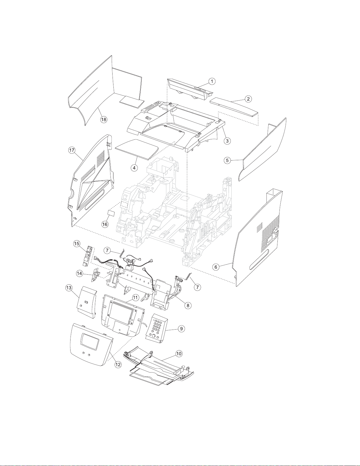
Assembly 1: Covers—printer (model X642e)
7-2 Service Manual
Page 3

7002-xxx
Assembly 1: Covers—printer (model X642e)
AsmIndex
1—1 40X0001 1 1 Fuser wiper cov er assembly
10 40X0493 1 1 Multipurpose tray assembly
11 40X3301 1 1 LCD mono touchscreen displa y assem bly—X642e, includes:
12 40X3299 1 1 Cover bezel with Lexmark logo—X642e, incl udes
13 40X3302 1 1 Operator panel left cover assembly—X642e, includes
14 40X0151 1 1 USB board assembly
Part
number
2 40X0469 1 1 Upper sub cover assembly
3 40X0467 1 1 Upper cover assembly
4 40X0468 1 1 Upper tray cover (paper support)
5 40X0473 1 1 Right side cover
6 40X0471 1 1 Right cover assembly
7 40X0516 2 1 Counterbalance spring
8 40X3309 1 1 Upper front cover hinge assemb ly—X642e, includes:
9 40X3303 1 1 Operator panel right cover assem bly—X642e, in cludes:
Units/
mach
Units/ kit
or pkg
Description
• Operator panel frame (hinge)
• UICC 18-pin cable
• USB cable
• Cover open sensor
• Left hinge cable retainer
• Right hinge cable retainer
• Left hinge spring
• Right hinge spring
• Ground cable
• Screw, M3x10 (3 )
• Screw, Sunk head (1)
• Operator panel right cover
• Dial numeric pad key
• Control 1—Stop key
• Control 2—Go key
• Control 3—Clear key
• Hook, operator panel right assembly
• Compression spring
• LCD operator panel cap
• UICC #1 card assembly
• Screw, M3x8 (2 )
• Screw, M3x8 (2 )
• LCD lower cover
• Mono LCD assembly
• LCD frame lev er
• LCD lever spring
• Core
• Screw, M3x8 (4 )
• Bezel
• UICC #3
• Home key
• M3x8 screws (2)
• Operator left cover
• Operator panel left hook
• Admin key
• UICC #2 card assembly
• Compression spring
• M3x18 screws (2)
• M3x18 screws (2)
Parts catalog 7-3
Page 4
7002-xxx
Assembly 1 (continued): Covers—printer ( m odel X642 e)
7-4 Service Manual
Page 5

7002-xxx
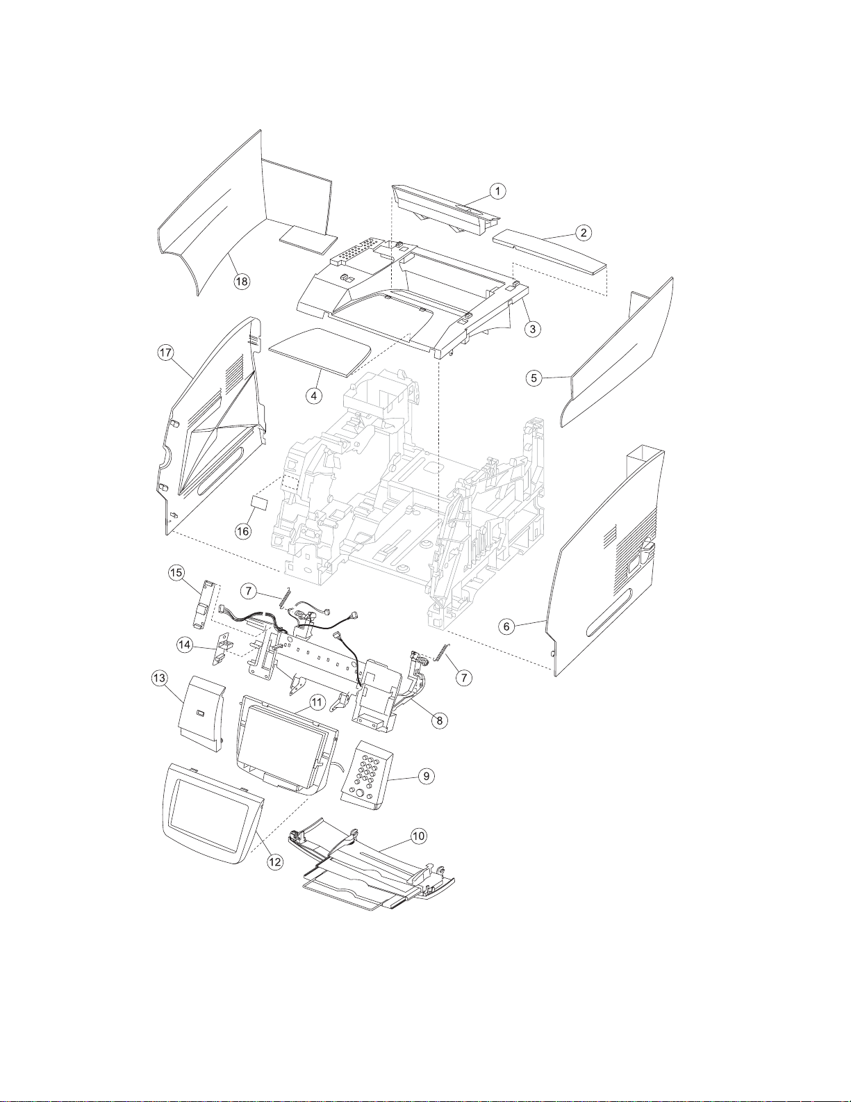
Assembly 1: Covers—printer (model X642e)
AsmIndex
1—15 40X3304 1 1 LCD (mono) touchscree n inverter card—X642e
16 40X0009 1 1 TLI/ID/serial number label—blank
17 40X0470 1 1 Left cover assembly
18 40X0472 1 1 Left side cover
NS 5 10 Parts packet (cable ties) (PP 40X0174)
NS 40X0050 2 1 Counterbalance spring
Part
number
Units/
mach
Units/ kit
or pkg
Description
Parts catalog 7-5
Page 6
7002-xxx
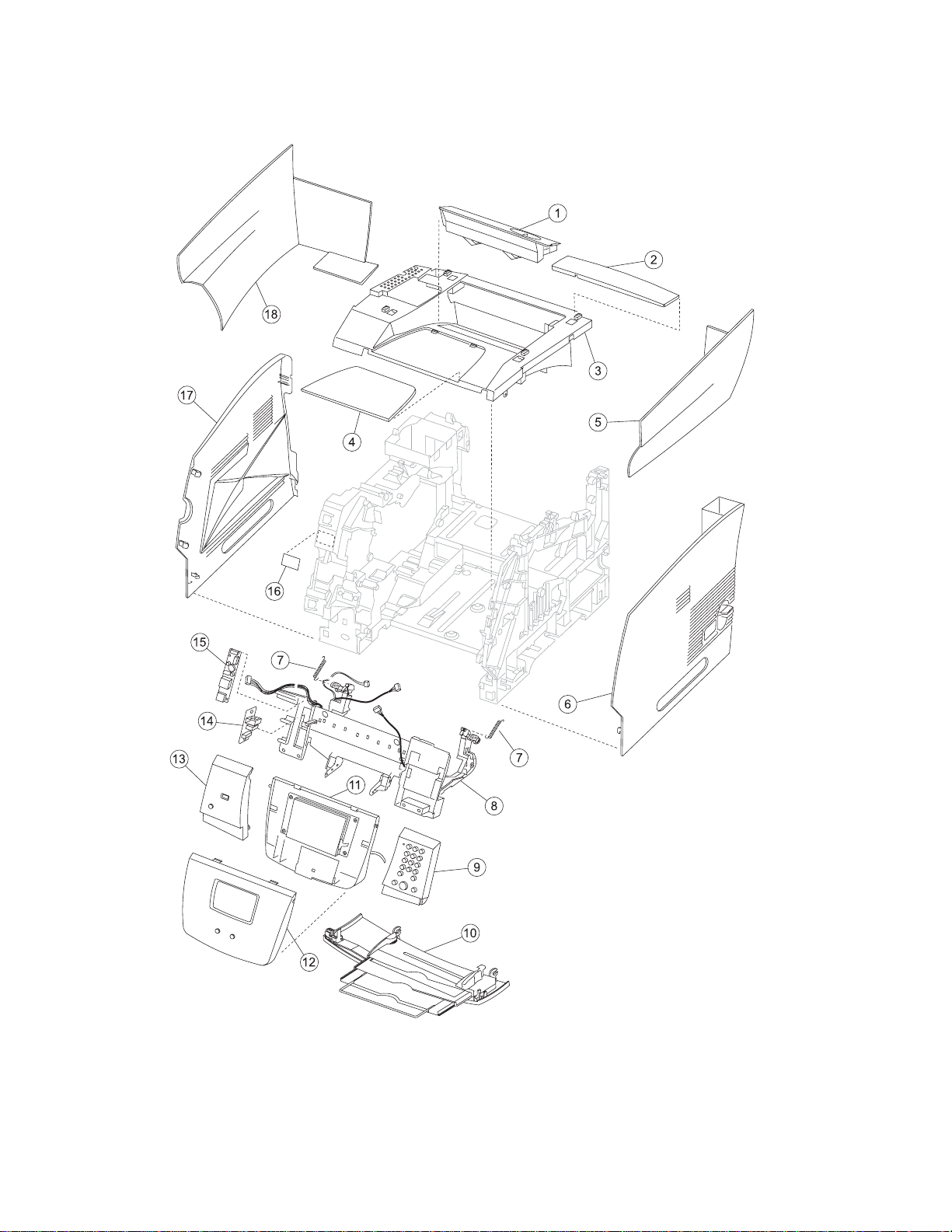
Assembly 2: Cover—printer (models X644e and X646e)
7-6 Service Manual
Page 7

7002-xxx
Assembly 2: Covers—printer (models X644e and X646e)
AsmIndex
2—1 40X0001 1 1 Fuser wiper cov er assembly
10 40X0493 1 1 Multipurpose tray assembly
11 40X0494 1 1 LCD touchscreen display assembly—X644e/X646e
12 40X3313 1 1 Cover bezel with Lex m ark log o—X644e
12 40X0476 1 1 Cover bezel with Lex m ark log o—X646e
13 40X0495 1 1 Operator panel left cover assembly—X644e/X646e
14 40X0151 1 1 USB board assembly
15 40X0497 1 1 LCD touchscreen inverter card
16 40X0009 1 1 TLI/ID/serial number label—blank
17 40X0470 1 1 Left cover assembly
18 40X0472 1 1 Left side cover
NS 5 10 Parts packet (cable ties) (PP 40X0174)
NS 40X0050 2 1 Counterbalance spring
Part
number
2 40X0469 1 1 Upper sub cover assembly
3 40X0467 1 1 Upper cover assembly
4 40X0468 1 1 Upper tray cover (paper support)
5 40X0473 1 1 Right side cover
6 40X0471 1 1 Right cover assembly
7 40X0516 2 1 Counterbalance spring
8 40X0515 1 1 Upper front cover hinge assemb ly—X644e/X646e, includes:
9 40X0496 1 1 Operator panel right cover assembly—X644e/X646e, includes:
Units/
mach
Units/ kit
or pkg
Description
• Cable, VICC 18-pi n
• Hinge, opera tor panel
• USB cable (1)
• Cover open switch and cable (1)
• Left cable re tain er ( 1 )
• Righ t cable re tain er (1)
• Left hinge spring (1)
• Right hinge spring (1)
• Stop button (1)
• Go button (1)
• Clear button (1)
• LED cap (1)
• Dial number pad
• User interface control card assembly
• Compression spring
• Operator panel right cover
• Operator panel right side hook
Parts catalog 7-7
Page 8
7002-xxx
Assembly 3: Covers—ADF scanner
7-8 Service Manual
Page 9

7002-xxx
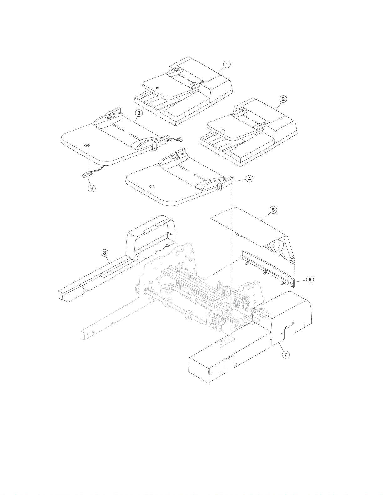
Assembly 3: Covers—ADF scanner
AsmIndex
3—1 40X0450 1 1 Complete ADF assembly—X644e/X646e
Part
number
2 40X3296 1 1 Complete ADF assembly—X642e
3 40X0451 1 1 Document tray assembly—X644e/X646e
4 40X3297 1 1 Document tray assembly—X642e
5 40X0452 1 1 ADF top cover ass em bly
6 40X0463 1 1 ADF scan cover
7 40X0465 1 1 ADF rear cover
8 40X0464 1 1 ADF front cover
9 1 1 Parts packet, sensors (PP 40X0481)
Units/
mach
Units/ kit
or pkg
Description
Parts catalog 7-9
Page 10
7002-xxx
Assembly 4: Frame 1
7-10 Service Manual
Page 11

7002-xxx
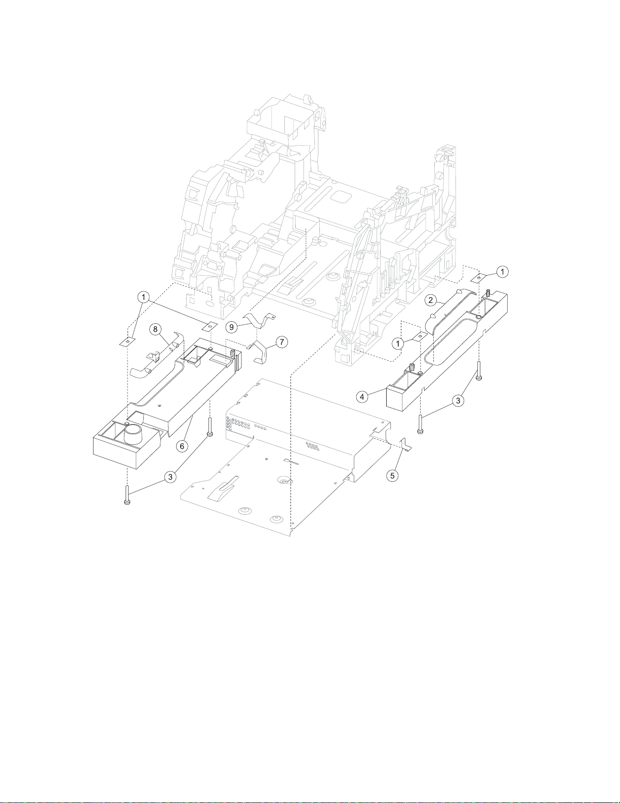
Assembly 4: Frame 1
AsmIndex
4—1 40X0065 4 1 Fr ame extension, nut plate
Part
number
2 40X0225 1 1 Right side hand holder
3 4 4 Parts packet (PP 40X0165)
4 40X0024 1 1 Right frame extension
5 40X0026 1 1 Right side frame ground contact
6 40X0025 1 1 Left frame extension
7 40X0060 1 1 External ground clip
8 40X0231 1 1 Left side hand holder
9 40X0285 1 1 Fr am e clip
Units/
mach
Units/ kit
or pkg
Description
Parts catalo g 7-11
Page 12
7002-xxx
Assembly 5: Frame 2
7-12 Service Manual
Page 13

7002-xxx
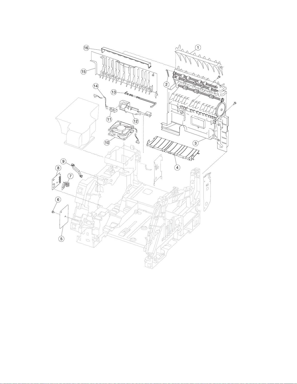
Assembly 5: Frame 2
AsmIndex
5—1 40X0027 1 1 Upper redrive defl ector
10 40X0054 1 1 Main fan with cable—500-sheet output
11 40X0051 1 1 Standard bin level sensor
12 40X0052 1 1 Standard bin level sensor bracket
13 40X0058 1 1 Output paper level flag
14 40X0264 1 1 Standard bin level sensor cable
15 40X0232 1 1 Redrive door assembly 500 sh eet
16 40X0059 1 1 Extension guide
NS 2 2 Parts packet, redrive mounting screws (P/N 40X0254)
Part
number
2 40X0028 1 1 Upper diverter spring
3 40X0030 1 1 Redrive assembly—500-sheet in/500 out
4 40X0032 1 1 Transfer deflector with brush
5 40X0044 1 1 Gear guard
6 1 Parts packet (PP 40X0165)
7 40X0048 1 1 Paper switch activate spring
8 40X0046 1 1 Paper size sensing board assembly
9 40X0049 1 1 Gear release link
Units/
mach
Units/ kit
or pkg
Description
Parts catalo g 7-13
Page 14
7002-xxx
Assembly 6: Frame 3
7-14 Service Manual
Page 15

7002-xxx
Assembly 6: Frame 3
AsmIndex
6—1 40X0249 1 1 EP DC fan assembly
10 40X0021 2 1 Cartridge holddown assembly
11 40X0040 1 1 Upper paper feed deflector
12 40X0042 1 1 Inner paper feed deflector
13 40X0039 2 1 Developer support roller
14 40X0043 1 1 Input sensor
15 40X0209 1 1 Gear #60 MPF shield
16 40X0045 1 1 ESD shield with label
17 40X0207 1 1 EP duct
Part
number
2 40X0208 1 1 Blower duct
3 1 1 Parts packet (PP 40X0165)
3 1 1 Parts packet (PP 40X0165)
4 40X0034 1 1 Signature button contact assembly with cable
5 40X0033 4 1 Machine mounting pad
6 40X0223 1 1 HVPS/input sensor /t oner sensor cable assembly
7 40X0036 1 1 Toner sensor assembly
8 40X0306 1 1 High volta ge contact kit, including:
9 40X0213 1 1 Tray bias assembl y
Units/
mach
Units/ kit
or pkg
Description
• Charge roll contact (1)
• Doc/TAR/Dev contact (3)
• PC drum contact (1)
• Screw (5)
• Screw blo ck (4 )
Parts catalo g 7-15
Page 16
7002-xxx
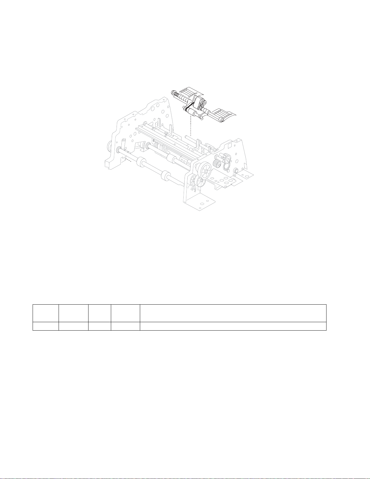
Assembly 7: Scanner automatic document feeder (ADF)—pickup
AsmIndex
7—1 40X0453 1 Pickup assembly
Part
number
Units/
mach
Units/ kit
or pkg
Description
7-16 Service Manual
Page 17
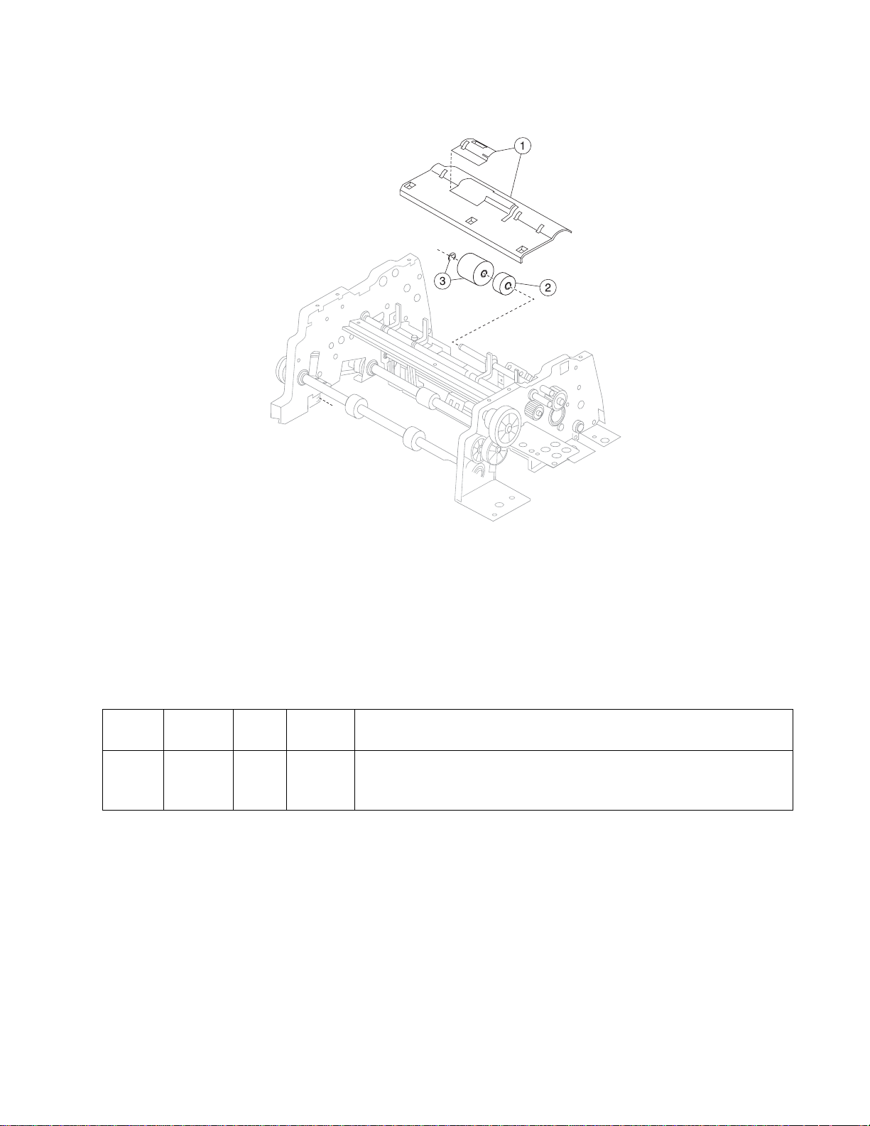
7002-xxx
Assembly 8: Scanner ADF—paper feed
AsmIndex
8—1 40X0459 1 1 Upper entrance guide ass em bly
Part
number
2 40X2799 1 1 Torque lim it er
3 40X0454 1 1 Reverse roller with clip
Units/
mach
Units/ kit
or pkg
Description
Parts catalo g 7-17
Page 18
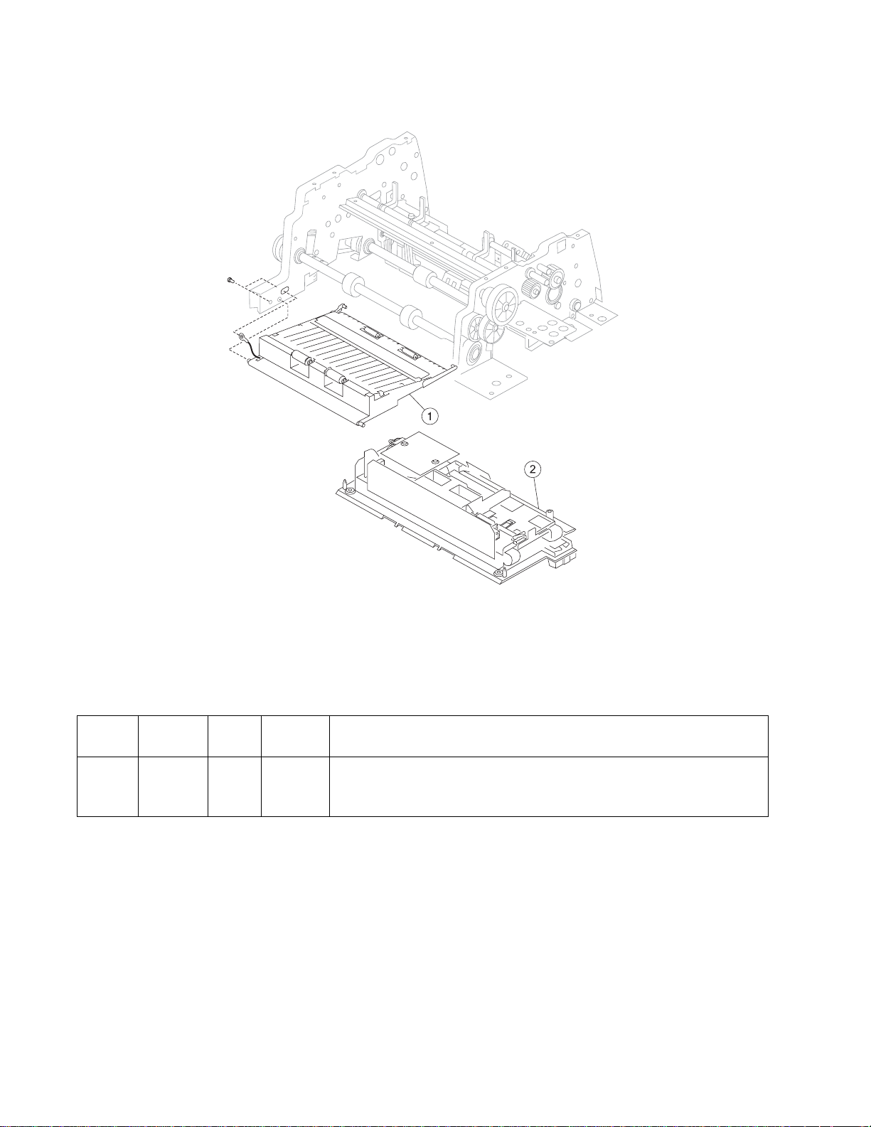
7002-xxx
Assembly 9: Scanner ADF—lower exit guide assembly
AsmIndex
9—1 40X0460 1 1 Lower exit guide assembly—X644e/X646e
Part
number
1 40X3311 1 1 Lower exit guide assembly—X642e
2 40X0458 1 1 ADF CCD module assembly—X644e/X646e only
Units/
mach
Units/ kit
or pkg
Description
7-18 Service Manual
Page 19
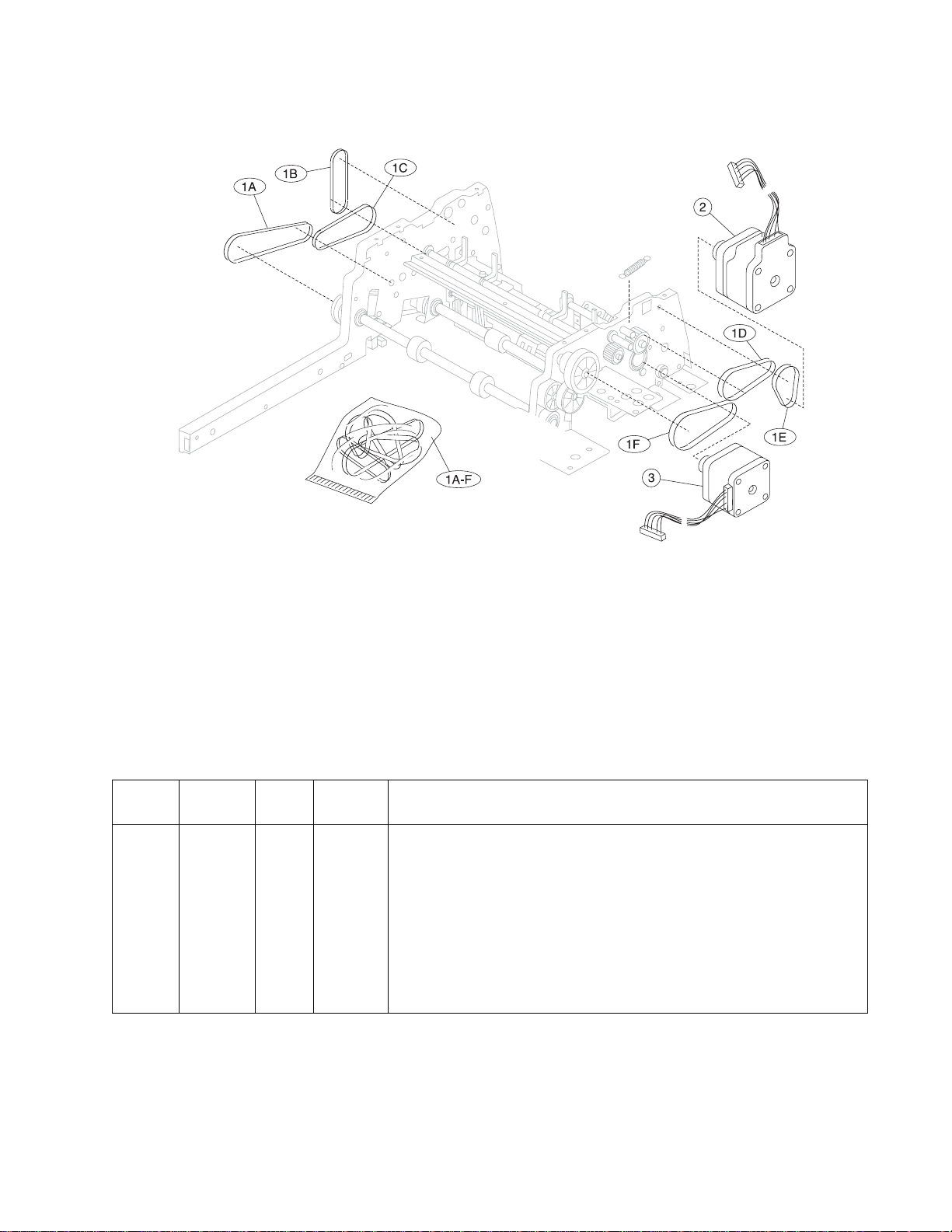
7002-xxx
Assembly 10: Scanner ADF— m otors and belts
AsmIndex
10—1 40X0482 1 1 Belts, includi ng:
Part
number
2 40X0461 1 1 Feed motor (ADF f eed)
3 40X0462 1 1 ADF scan motor assembly
Units/
mach
Units/ kit
or pkg
Description
• A—Timing belt 52M194
• B—Timing belt 52M172
• C—Timing belt motor 52M29 2
• D—Timing belt second t ransport 52M152
• E—Timing belt first transport 52M132
Note: Belt P/N stamped on belt.
• F—Timing belt knob 52M172
Parts catalo g 7-19
Page 20
7002-xxx
Assembly 11: Scanner ADF—sensors
7-20 Service Manual
Page 21

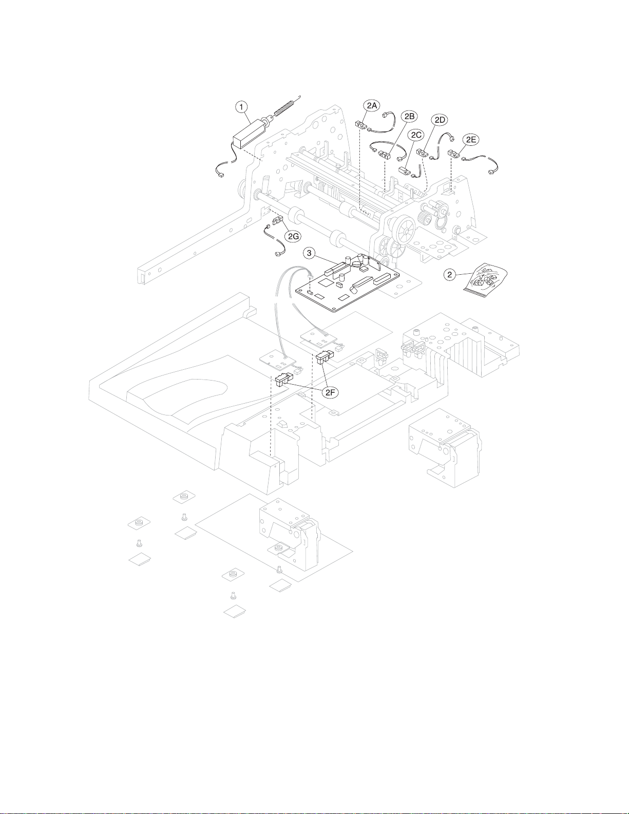
7002-xxx
Assembly 11: ADF—sensors
AsmIndex
11—1 40X0456 1 1 Pickup arm assembly solenoid
Part
number
2 40X0481 1 4 Parts packet, sensors
3 40X0486 1 1 Motor driver card
Units/
mach
Units/ kit
or pkg
Description
• A—Second scan sensor
• B—Paper pr esent
• C—Interval sensor
• D—First scan sensor
• E—ADF top cover open
• F—Flatbed co ver open
• G—Jam access door
Note: There are four different sensors i n the parts packet, some of the
same sensors are used in di fferent loc ati ons.
Parts catalo g 7-21
Page 22
7002-xxx
Assembly 12: Scanner—flatbed
7-22 Service Manual
Page 23

7002-xxx
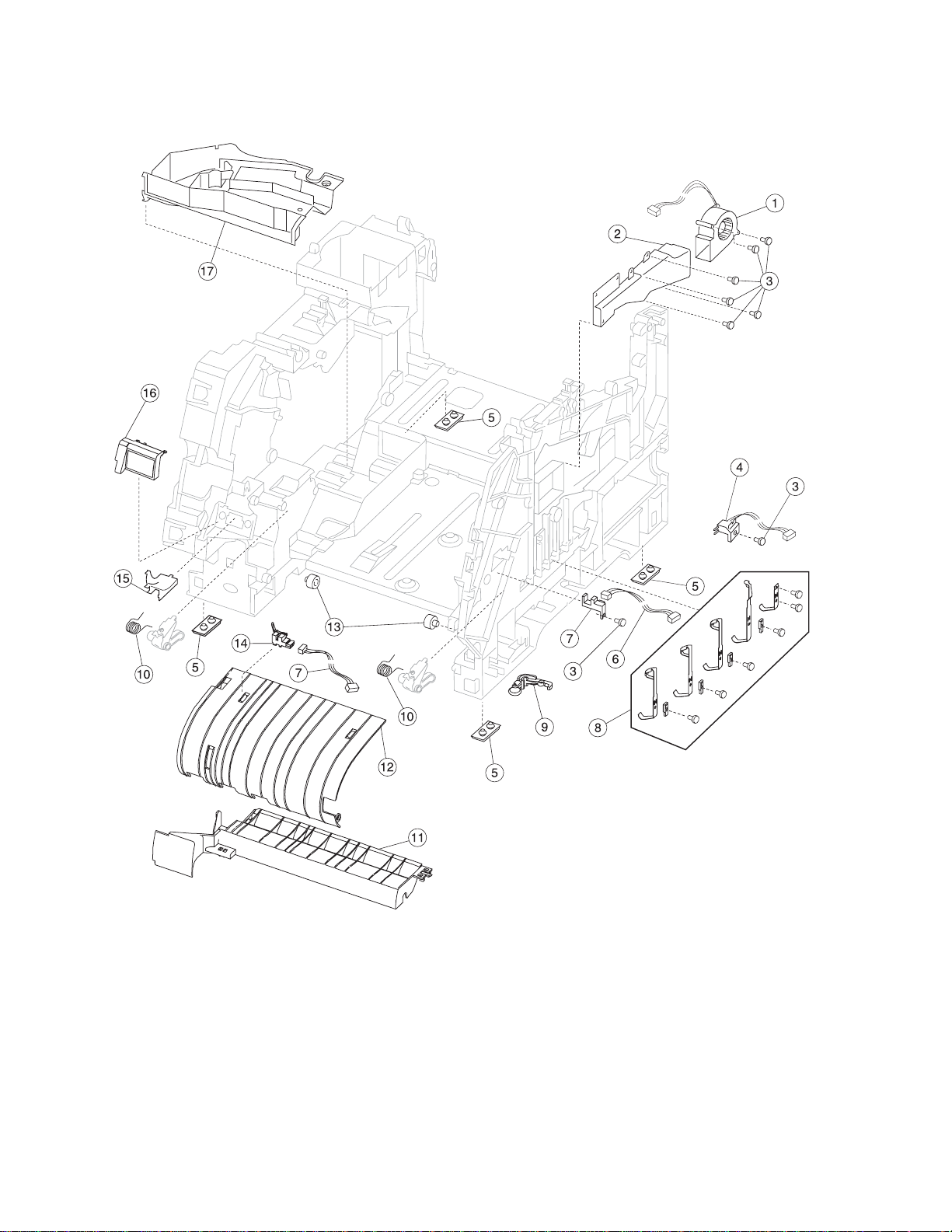
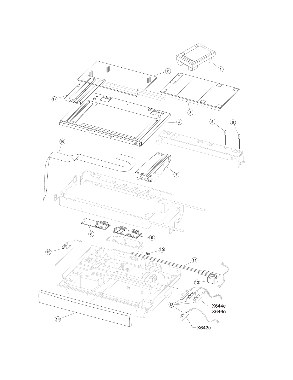
Assembly 12: Scanner—flatbed
AsmIndex
12—1 40X3298 1 1 Complete flatbed scanner assembly —X642e
10 40X0490 1 1 Belt tension spring
11 40X0479 1 1 Flatbed CCD drive belt
12 40X0480 1 1 Flatbed scan motor, includi ng fl atbed scan motor to flatbed interconnect
13 40X0491 1 1 Flatbed paper size sensor assem bly (assemb ly includes 3 sensors)—
13 40X0491 1 1 Flatbed paper siz e sensor assembl y (assembly includes 3 sensors but only
14 40X0474 1 1 Front cover
15 40X0481 1 1 Parts packet, sensors (home sensor)
16 40X0487 1 1 Flatbed CCD ribbon cable
17 40X0484 1 1 Glass holder assembly
Part
number
1 40X0457 1 1 Complete flatbed scanner assembly —X64 4e/X644e
2 40X0483 1 1 Flatbed contac t glass
3 40X0466 1 1 Flatbed white cushion
4 40X0475 1 1 Scan cover
5 40X0513 1 1 Flatbed cover closed actuator
6 40X0514 1 1 Flatbed cover closing actuator
7 40X0478 1 1 Flatbed CCD module assembly
8 40X3312 1 1 Flatbed interconnect card assembly—X642e
9 40X0485 1 1 Flatbed interconnect card assembly—X644e/X646e
Units/
mach
Units/ kit
or pkg
Description
card cable
X644e/X646e
one sensor is required)—X642e
Parts catalo g 7-23
Page 24

7002-xxx
Assembly 13: Printhead
AsmIndex
13—1 40X0061 1 1 Laser printhead cab le assembly
Part
number
2 Parts packet (PP 40X0165) (printhead mounting screw)
3 40X0062 1 1 Printhead assembly (includes all cab les)
Units/
mach
Units/ kit
or pkg
Description
CAUTION
The printhead is n ot a servi ceable FRU. Do not disas sembl e
the printhead.
7-24 Service Manual
Page 25

7002-xxx
Assembly 14: Paper feed—autocompensator
AsmIndex
14—1 40X0066 1 1 Pick arm assembly —500-sheet
Part
number
2 40X0069 1 1 Parts packet, bellcrank assembly for— 500-sheet tra y
3 40X0070 2 2 Pick tires, pick roll assembly
4 40X0072 1 1 Paper out flag— 500-sheet tray
5 40X0215 1 1 Paper low/out sensor card assemb ly, 500-sheet
6 Parts packet (PP 40X0165) (hanger)
7 40X0074 1 1 Paper size/autocompensator cable
Units/
mach
Units/ kit
or pkg
Description
• Bellcran k (1 )
• Spring (1)
Parts catalo g 7-25
Page 26

7002-xxx
Assem bly 15: Paper feed—multipurpose feeder
7-26 Service Manual
Page 27

7002-xxx
Assembly 15: Paper feed—multipurpose feeder
AsmIndex
15—1 40X0079 1 1 Multipurpose f eeder lower defle ctor assembly
NS 1 Parts packet (PP 40X0165) (pick roll shaft clip)
Part
number
2 40X0310 1 1 Multipurpose feeder pick arm assembly with solenoid
3 40X0076 1 1 Pick roll assembly
4 40X0077 1 1 Multipurpose feeder paper out flag
5 1 Parts packet (PP 40X0165) (low er def lector mounting scr ew, 8 mm)
5 1 Parts packet (PP 40X0165) (low er def lector mounting scr ew, 12 mm)
5 1 Parts packet (PP 40X0165) (frame mounting screw)
Units/
mach
Units/ kit
or pkg
Description
Parts catalo g 7-27
Page 28

7002-xxx
Assembly 16: Paper feed—alignment
7-28 Service Manual
Page 29

7002-xxx
Assembly 16: Pa per feed—alignment
AsmIndex
16—1 40X0084 1 1 Paper feed alignment assembly paper feed
NS 1 1 Parts packet (PP 40X0165) (alignment asm mounting screw)
Part
number
2 1 Parts packet (PP 40X0165) (clip ref ground mounting screw)
3 40X0085 1 1 Reference ground clip
4 40X0086 1 1 Parts packet (reference adjust)
Units/
mach
Units/ kit
or pkg
Description
• Screw, paper reference adjust (1)
• Washer, paper reference adjust (1)
• Nut, paper reference adjust (1)
Parts catalo g 7-29
Page 30

7002-xxx
Assembly 17: Integrated 500-sheet paper tray
7-30 Service Manual
Page 31

7002-xxx
Assembly 17: Integrated 500-sheet paper tray
AsmIndex
17—1 40X0098 1 1 Tray assembly—500-sheet tra y
Part
number
2 40X0099 1 1 Side restraint
3 40X0182 4 1 Wear strip
4 40X0103 1 1 Pass t hru plate—500-sheet tray
5 40X0183 1 1 Wear plate—500-sheet tray
6 40X0105 2 1 Restraint pad
7 40X0106 1 1 Back restraint
Units/
mach
Units/ kit
or pkg
Description
Parts catalo g 7-31
Page 32

7002-xxx
Assembly 18: Drives—Main drive and developer drive
7-32 Service Manual
Page 33

7002-xxx
Assembly 18: Drives—Main drive and developer drive
AsmIndex
18—1 40X0107 1 1 Gearbox with motor
NS 4 Parts packet (PP 40X0165) (gearbox mounting screw)
Part
number
2 40X0111 1 1 Power takeoff shaft—500-sheet
3 40X0112 1 1 Power takeoff shaft spring
4 40X0113 1 1 Bev el gear with grease packet and washer
5 40X0114 1 1 Developer drive assembly
6 40X0115 Parts packet, developer drive
7 3 Parts packet (PP 40X0165) (developer drive ground screw)
Units/
mach
Units/ kit
or pkg
Description
• Bevel gear (1)
• Instruction sheet (1)
• Grease pack et (1)
• washer (1)
• Developer drive shaft (1)
• shaft, coupl er gear #55 (1)
Parts catalo g 7-33
Page 34

7002-xxx
Assembly 19: Hot roll fuser
7-34 Service Manual
Page 35

7002-xxx
Assembly 19: Hot roll fuser
AsmIndex
19—1 40X2592 1 1 Fuser assembly w/115 V lamp
10 40X0230 1 1 Exit sensor cable
11 40X0238 1
12 40X0124 1 1 Narrow media sensor
13 40X0229 1 1 Narrow media sensor cable
NS 40X0226 1 1 Fuser AC to fuser lamp cable
Part
number
1 40X2591 1 1 Fuser assembly w/100 V lamp
1 40X2590 1 1 Fuser assembly w/220 V lamp
2 40X0120 1 1 Fuser wiper cav it y cover
3 40X0122 1 1 Fuser lamp, 115V
3 40X0123 1 1 Fuser lamp, 220V
4 40X0121 1 Fuser cover assem bly kit, inc luding:
5 Parts packet (fuser mounting screw) (PP 40X0254)
6 40X0239 1 Exit sensor flag/ spri ng kit, including:
7 40X0236 1 1 Exit/narrow media sensor cover
8 Parts packet (PP 40X0165)
9 40X0125 1 1 Exit sensor
Units/
mach
Units/ kit
or pkg
1
1
Description
• Thermistor (1)
• Thermostat (1)
• Left and right fuser lamp contact assemblies (1)
• Spring (1)
• Flag (1)
Narrow media fl ag/spring kit, including:
• Spring
• Flag
Parts catalo g 7-35
Page 36

7002-xxx
Assembl y 20: Transfer/charging
7-36 Service Manual
Page 37

7002-xxx
Assembly 20: Transfer/charging
AsmIndex
20—1 40X0126 1 Parts kit, charge roll link asm, left side
NS 1 Parts packet (PP 40X0165) (charge roll screw)
NS 1 Parts packet (PP 40X0165) (C-clip, pivot shaft)
Part
number
2 40X0127 1 2 Charge roll assemb ly, dual
3 40X0129 1 Parts kit, right side charge roll link assembly
4 40X0130 1 1 Transfer roll assembly
5 40X0131 1 1 Transfer roll assembly right arm
6 40X0132 1 1 Transfer roll right spring
7 40X0133 1 1 Transfer pivot shaft
8 40X0134 1 1 Transfer roll left spri ng
9 40X0135 1 1 Transfer roll left arm
Units/
mach
Units/ kit
or pkg
Description
Parts catalo g 7-37
Page 38

7002-xxx
Assembly 21: Electronics—power supplies
7-38 Service Manual
Page 39

7002-xxx
Assembly 21: Electronics—power supplies
AsmIndex
21—1 40X0517 1 1 LVPS/AIO—115 V ac
Part
number
1 40X0518 1 1 LVPS/AIO—220 V ac
2 40X0260 1 1 Po wer cord set (8 ft right angle, 13 amp)—United States, Canada,
2 40X0256 1 1 Power cord set (8 ft right angle)— Boli via and Peru
2 40X0255 1 1 Po wer cord set (8 ft right angle)—Argentina
2 40X0257 1 1 Po wer cord set (8 ft right angle)—Chile, Uruguay
2 40X0258 1 1 Po wer cord set (8 ft right angle)—Arabic , Austria, Belgiu m, Blu ema rk, CIS,
2 40X0293 1 1 Po wer cord set (8 ft right angle)—Angui ll a (UK), Antigua and Barbuda,
2 40X0259 1 1 Po wer cord set (6 ft right angle)—Bra zil
2 40X0301 1 1 Po wer cord set (8 ft straight) — AS/NZS
2 40X0271 1 1 Power cord set (8 ft straight)—Hong Kong
2 40X0302 1 1 Power cord set (8 ft right angle)— Japan
2 40X0280 1 1 Power cord set (6 ft straight)—Kor ea
2 40X0303 1 1 Po wer cord set (8 ft straight)—PRC
2 40X0281 1 1 Power cord set (6 ft right angle)— Taiwan
2 40X0294 1 1 Po wer cord set (8 ft right angle)—Denm ark, Norway, and Swe den
2 40X0295 1 1 Power cord set (8 ft right angle)— Isr ael
2 40X0304 1 1 Po wer cord set (8 ft right angle)—Botswana, Lesotho, Namibia, Pakistan,
2 40X0305 1 1 Po wer cord set (8 ft right angle)—Switzerland
3 56P4244 1 1 High volta ge power supply
4 1 Parts packet (PP 40X0165)
5 40X0223 1 1 Front cable harness (HVPS/input sensor/toner sensor)
Units/
mach
Units/ kit
or pkg
Description
Caribbean countries, Colombia, Costa Rica, Domini can Republic, El
Salvador, Equator, Guatemala, Honduras, Mexico, Nicaragua, Panama,
Puerto Rico, Saudi Ara bia, Venezuela, and Virgin Islands
Czechoslovakia, Denmark, Finland, France, Germany, Greece, Hungary,
Ireland, Ital y, Medmark, (1 and 2), Netherlands, Norway, Paraguay, Poland,
Portugal, Russia, Slavic countries, Spain, Sweden, Turkey, and UK.
Bahrain, Bots wana, Burma (Myanmar), Channel I slands, Cyprus , Dominica,
Falkl and Islands , Gambia, Ghana, Gibr altar , Grenada, Guyana, Hong K ong,
Iraq, I rel and, Isle of Ma n, Jordan, Kenya, Kuwait, Lebanon, Liberia, M alawi,
Malaysia, Malta, Mauritius, Montserrat, Nigeria, Oman, Pakistan, Pitcairn
Island (UK), Qatar , Scotland, Seychel les , Sierra Leone , Singapore , St. Kitts
and Nevis, St. Lucia, St. Vincent and Grenadines, Sudan, Tanzania,
Trinidad and Tobago , Uganda, United Arab Emirates , United Kingdom,
Vanuatu, Wales, Yemen, Zambia, Zimbabwe.
and South Africa
Parts catalo g 7-39
Page 40

7002-xxx
Assembl y 22: Electronics—ca rd assemblies
7-40 Service Manual
Page 41

7002-xxx
Assembly 22: Electronics—card assemblies
AsmIndex
22—1 40X3305 1 1 Scanner control card—X642e
NS 40X3478 1 1 Forms card assemb ly—X642e
NS 40X4179 1 1 Forms card assemb ly—X644e/X646e
Part
number
1 40X0498 1 1 Scanner control card—X644e/X646e
2 40X0509 1 1 Hard disk IDE 50-pin cab le—X646e
3 40X0489 1 1 Hard disk assembly—X646e
4 40X0520 1 1 Interface card assembly
5 40X0510 1 1 Hard disk 4-pin power cable—X646e
6 40X3310 1 1 System board assemb ly—X642e (Board ID M010 6030)
6 40X2722 1 1 System board assemb ly (network)—X644e/ X646e (Board ID M010 6000)
7 40X3477 1 1 Bar code card assembly—X642e
7 40X2792 1 1 Bar code card assembly—X644e/X646e
7 40X2529 1 1 IPDS SCS/TNe card assembl y— X644e/X646e
7 40X2793 1 1 PRESCRIBE card assembly—X644e/X646e
7 40X3479 1 1 PrintCryption card assembly—X642e
7 40X4178 1 1 PrintCryption card assembly—X644e/X646e
8 40X0519 1 1 Modem card assembly
9 40X0507 1 1 Modem 30-pin cable
Units/
mach
Units/ kit
or pkg
Description
Note: The system board has a label with an board ID and barcode. Use the first eigh t numbers to identify the
board with the part number in the table above:
Parts catalo g 7-41
Page 42

7002-xxx
Assembly 23: Electronics—shields
AsmIndex
23—1 40X0150 1 1 Outer shield
NS 40X0152 1 1 Ethernet shield (blank)
Part
number
2 Parts packet (PP 40X0165) (INA cover mounting screw)
2 Parts packet (PP 40X0165) (outer shield mounting screw)
2 Parts packet (PP 40X0165) (inner shield mounting screw)
3 40X0149 1 1 Inner shield assembly
4 40X0153 1 1 INA flat cover (blank)
Units/
mach
Units/ kit
or pkg
Description
7-42 Service Manual
Page 43

7002-xxx
Assembly 24: Cabling diagram 1
1
2
3
AsmIndex
24—1 40X0223 1 1 HVPS/input sensor /t oner sensor cable assembly
Part
number
2 40X0160 1 1 MPF sensor cable
3 40X0264 1 1 Standard bin level sensor cable
Units/
mach
Units/ kit
or pkg
Description
Parts catalo g 7-43
Page 44

7002-xxx
Assembly 25: Cabling diagram 2
1
AsmIndex
25—1 40X0061 1 1 Laser printhead cab le assembly
Part
number
2 40X0074 1 1 Paper size/aut ocom pensator cable
3 40X0046 1 1 Paper size sensin g board assembly
Units/
mach
Units/ kit
or pkg
Description
2
3
7-44 Service Manual
Page 45

7002-xxx
Assembly 26: Cabling diagram 3
AsmIndex
26—1 40X0034 1 1 Signature button contact assemb ly with cable
Part
number
2 40X0156 1 1 Bottom/front autoconnect cable assembly
3 40X0223 1 1 HVPS/input sensor /t oner sensor cable assembly
4 40X0224 1 1 LVPS to system board cable assembly
Units/
mach
Units/ kit
or pkg
Description
Parts catalo g 7-45
Page 46

7002-xxx
Assembly 27: Cabling diagram 4—model X642e
7-46 Service Manual
Page 47

7002-xxx
Assembly 27: Cabling diagram 4—model X642e
AsmIndex
27—1 40X3309 1 1 Upper front cover hinge assemb ly —X642e, includes
Part
number
2 40X0162 1 1 System board to fuser board cable assembly
3 40X0163 1 1 Fuser AC lamp to LVPS cable assembly
4 40X0226 1 1 Fuser connector (fuser AC to fuser lamp)
Units/
mach
Units/ kit
or pkg
Description
• 1A—Operator panel to LCD Inverter card cabl e (2- pin)
• 1B—Operator panel card to UICC #2 card cable (8-pin)
• 1C—U S B cabl e (1 )
• 1D—Cover open switch/cable from system boar d
• 1E—LCD display to operator panel card cable (14-pin ribbon)
• 1F—Operator panel cable from SCC
• 1G—Operator panel card to bezel card cable (4-pin)
• 1H—LCD display to operator panel card cable (4-pin)
• 1J—Operator panel to LCD inverter card cable (2-pin)
Parts catalo g 7-47
Page 48

7002-xxx
Assembly 28: Cabling diagram 4—mode ls X644e/X646e
7-48 Service Manual
Page 49

7002-xxx
Assembly 28: Cabling diagram 4—models X644e/X646e
AsmIndex
28—1 40X0515 1 1 Upper front cover hinge assemb ly —X644e/X646e, includes:
Part
number
2 40X0162 1 1 System board to fuser board cable assembly
3 40X0163 1 1 Fuser AC lamp to LVPS cable assembly
4 40X0226 1 1 Fuser connector (fuser AC to fuser lamp)
Units/
mach
Units/ kit
or pkg
Description
• 1A—LCD display to LCD inverter card cable (2-pin)
• 1B—Operator pan el card to LCD inverter card cable (8-pin)
• 1C—U S B cabl e (1 )
• 1D—Cover open switch/cab le (1)
• 1E—LCD display to operator panel cable (14-pin)
• 1F—Operator panel cable to SCC card (1)
• 1G—LCD display to operator panel ca ble (4-pin)
Parts catalo g 7-49
Page 50

7002-xxx
Assembly 29: Cabling diagram 5
3
3
1
2
3
4
5
7-50 Service Manual
Page 51

7002-xxx
Assembly 29: Cabling diagram 5
AsmIndex
29—1 40X0310 1 1 Multipurpos e feeder pick arm assembly with solenoid
Part
number
2 40X0159 1 1 Main drive motor cable assembly
3 40X0249 1 1 EP DC fan assembly
4 40X0054 1 1 Main fan with cable, 500- sheet output
5 40X0161 1 1 Ground cable
Units/
mach
Units/ kit
or pkg
Description
Parts catalo g 7-51
Page 52

7002-xxx
Assembly 30: Cabling diagram 6—model X642e
7-52 Service Manual
Page 53

7002-xxx
Assembly 30: Cabling diagram 6—model X642e
AsmIndex
30—1 40X0491 1 1 Flatbed paper si ze sensor assembl y (3 sensors are included in the
Part
number
2 40X0481 1 1 Parts packet, sensors (home sensor)
3 40X0487 1 1 Flatbed CCD ribbon cabl e
4 40X0507 1 1 Modem 30-pin cable
5 NA 1 1 Flatbed interconnect c ard (CN1) to SCC c ard cab le (J 15) (NO T AVAILABLE
6 NA 1 1 Flatbed interconnect card (CN4) to home sensor cable (NOT AVAILABLE
7 40X0480 1 1 Flatbed scan motor, including flatbed scan motor t o flatbed interconnect
8 NA 1 1 Flatbed paper size sensor to interconnect card cable (CN3) (NOT
Units/
mach
Units/ kit
or pkg
Description
assembly, model X642e uses only one)
AS A FRU)
AS A FRU)
card cabl e
A VAILABLE AS A FRU)
Parts catalo g 7-53
Page 54

7002-xxx
Assembly 31: Cabling diagram 6—models X644e/X646e
7-54 Service Manual
Page 55

7002-xxx
Assembly 31: Cabling diagram 6—models X644e/X646e
AsmIndex
31—1 40X0491 1 1 Flatbed paper si ze sensor assembl y (3 sensors are included in the
10 NA 1 1 Home sensor to flatbed inter connect card (Cn4) (NO T AVAILABLE AS A
11 40X0480 1 1 Flatbed scan motor, including scan motor
Part
number
2 NA 1 1 Flatbed paper size sensor cable to flatbed interconnect card (CN3) (NOT
3 40X0481 1 1 Parts packet, sensors (home sensor)
4 40X0487 1 1 Flatbed CCD ribbon cabl e
5 40X0509 1 1 Hard disk IDE 50-pin cab le—X646e
6 40X0510 1 1 Hard disk 4-pin power cable—X646e
7 40X0507 1 1 Modem 30-pin cable
8 NA 1 1 Scanner control card (J1) to flatbed interconnect card (CN1) cable (NOT
9 NA 1 1 Scanner control card (J28) to flatbed interconnect card (CN5) (NOT
Units/
mach
Units/ kit
or pkg
Description
assembly, model X642e uses only one)
A VAILABLE AS A FRU)
A VAILABLE AS A FRU)
A VAILABLE AS A FRU)
FRU)
Parts catalo g 7-55
Page 56

7002-xxx
Assembly 32: Cabling diagram 7
4
3
1A
2
1B
1C
1D
AsmIndex
32—1 40X0481 1 1 Parts packet, sensors
Part
number
2 40X0456 1 1 Pickup arm assembly solenoid
3 40X0486 1 1 Motor driver card
4 NA 1 1 Paper present sensor cable (NOT AVAILABLE AS A FR U)
Units/
mach
Units/ kit
or pkg
Description
• A—Second scan sensor
• B—Jam access door sensor
• C—First scan sensor
• D—Interval sensor
7-56 Service Manual
Page 57

7002-xxx
Assembly 33: Cabling diagram 8—model X642e
AsmIndex
33—1 40X0481 1 1 Parts packet, sensors
Part
number
2 NA 1 1 Feed motor cable (NOT AVAILABLE AS A FR U)
3 40X0506 1 1 MDC to flatbed interco nnect card 36-pin cable
4 NA 1 1 Flatbed cover open sensor cable (NOT AVAILABLE AS A FRU)
5 N/A 1 1 Transport motor cable (NOT AVAILABLE AS A FRU)
6 N/A 1 1 Paper length sensor cable, includes paper width sensor assembly—X644e/
Units/
mach
Units/ kit
or pkg
Description
• A—ADF top cover open sensor
• B—First scan sensor
• C—Flatbed cover closed sensors (cover closi ng, cover closed)
• D—ADF paper length sensor
X646e
Parts catalo g 7-57
Page 58

7002-xxx
Assembly 34: Cabling diagram 8—models X644e/X646e
1C
7
6
5
1C
1A
1B
2
AsmIndex
Part
number
4
Units/
mach
Units/ kit
or pkg
Description
3
34—1 40X0481 1 1 Parts packet, sensors
• A—ADF top cover open sensor
• B—First scan sensor
• C—Flatbed cover closed sensors (cover closi ng, cover closed)
• D—ADF paper length sensor
2 NA 1 1 Feed motor cable (NOT AVAILABLE AS A FR U)
3 40X0502 1 1 ADF CCD to flatbed interconnect card 36-pin cable—X644e/X646e
4 40X0506 1 1 MDC to flatbed interco nnect card 36-pin cable
5 NA 1 1 Flatbed cover open sensor cable (NOT AVAILABLE AS A FRU)
6 N/A 1 1 Transport motor cable (NOT AVAILABLE AS A FRU)
7 N/A 1 1 Paper length sensor cable, includes paper width sensor assembly—X644e/
X646e
7-58 Service Manual
Page 59

7002-xxx
Assembly 35: Optional 250-sheet paper drawer
AsmIndex
35—1 40X3230 1 1 250-sheet paper drawer, complete assembly
10 40X3234 1 1 Bin low sensor with cable
11 40X3233 1 1 Option pass thru sensor
12 99A0272 1 1 Drive shaft—250-sheet
13 99A0275 1 1 Power takeoff spring
14 40X3237 1 1 Base assembly
Part
number
2 1 1 Parts packet, scre ws (PP 99A0263) (switch spring)
3 99A0063 1 1 Switch activate spring
4 56P4129 1 1 Paper out arm—250-sheet
5 3 3 Parts packet, scre w s (PP 99A0263) (auto comp mounting)
5 4 4 Parts packet, scre ws (PP 99A0263)
6 40X3232 1 1 Pick arm assembly
7 56P1228 1 1 Bellcrank—250-sheet paper tray
8 99A1929 2 1 Bellcrank spring—250-sheet paper tray
9 40X0070 2 2 Pick roll assembly
Units/
option
Units/ kit
or pkg
Description
Parts catalo g 7-59
Page 60

7002-xxx
Assembly 36: Opti onal 250-sheet paper tray
AsmIndex
36—1 40X3231 1 1 Tray assembly, option—250-she et
Part
number
2 40X3235 1 1 Side restraint—250-sheet tray
3 56P1279 1 4 Wear strips
4 56P4230 1 1 Plate—250 sheet pass thru
5 99A0121 1 1 Plate—250-sheet tray wear
6 99A0120 1 2 Restraint pad
7 40X3236 1 1 Back restraint—250-sheet tray
Units/
option
Units/ kit
or pkg
Description
7-60 Service Manual
Page 61

7002-xxx
Assembly 37: Optional 500-sheet paper drawer
AsmIndex
37—1 40X3243 1 1 Drawer assem bly, complete—500-sheet
10 40X3245 1 1 Bin low sensor with cable
11 40X3247 1 1 Base assembly, 500-sheet
12 56P4145 1 1 Paper out arm—500-sheet drawer
13 99A0063 1 1 Switch activate spring
14 1 1 Parts packet, screws (PP 99A0263)
Part
number
2 3 3 Parts packet, scre w s (PP 99A0263) (auto comp mounting scr ew)
3 40X3246 1 1 Pick arm assembly—500 sheet
4 56P1228 1 1 Bellcrank spring arm
5 56P2540 1 1 Bellcrank spring—500-sheet opt ion tray
6 40X0070 1 2 Pick roll assembly
7 40X3244 1 1 Option pass t hru sensor
8 99A0275 1 1 Power takeoff spring
9 99A0447 1 1 Drive shaft—500 -sheet
Units/
option
Units/ kit
or pkg
Description
Parts catalo g 7-61
Page 62

7002-xxx
Assembly 38: Opti onal 500-sheet paper tray
AsmIndex
38—1 56P4150 1 1 Complete tray assembl y—500-sheet
Part
number
2 56P4137 1 1 Side restraint—500-sheet tray
3 99A0292 1 4 Wear strips
4 56P4196 1 1 Pass t hru plate
5 99A0120 1 2 Restraint pad
6 56P4195 1 1 Wear plate—500 sheet
7 56P4147 1 1 Back restraint—500-sheet tray
Units/
option
Units/ kit
or pkg
Description
7-62 Service Manual
Page 63

7002-xxx
Assembly 39: Duplex option
AsmIndex
39—1 56P4102 1 1 Duplex assembly—500-sheet
Part
number
Units/
option
Units/ kit
or pkg
Description
Parts catalo g 7-63
Page 64

7002-xxx
Assembl y 40: Envelope feeder
1
7-64 Service Manual
Page 65

7002-xxx
Assembly 40: Envelope feeder
AsmIndex
40—1 40X3248 1 1 Complete envelope option
Part
number
Units/
option
Units/ kit
or pkg
Description
Parts catalo g 7-65
Page 66

7002-xxx
Assem bly 41: High-capa city feeder 1
7-66 Service Manual
Page 67

7002-xxx
Assembly 41: High capacity feeder 1
AsmIndex
41—1 40X3250 1 1 Complete option assembly (letter)
10 4 4 Parts packet, screws (PP 99A0675) (card asm. mounting)
11 4 4 Parts packet, screws (PP 99A0675) (card assembly mou nting screw)
11 99A0658 2 2 Door magnet
Part
number
1 40X3249 1 1 Complete option assembly (A4)
2 99A1818 1 1 Wear dimple strip
3 99A0681 4 1 Wear strip
4 40X3254 1 1 Fro nt door assembly
5 56P4157 1 2 Door hinge
6 4 1 Parts packet, nuts (PP 99A0676) (6-32 hinge mounting nut)
7 4 1 Parts packet, washers (PP 99A0677) (hinge mounting flat w asher)
8 4 1 Parts packet, washers (PP 99A0677) (hinge mounting star washer)
9 40X3252 1 1 2000-sheet option control card assembly
Units/
option
Units/ kit
or pkg
Description
Parts catalo g 7-67
Page 68

7002-xxx
Assem bly 42: High-capa city feeder 2
AsmIndex
42—1 99A0654 1 1 Paper low switch
Part
number
2 Parts packet, nuts (PP 99A0676)
3 40X3262 1 1 AC ext ernal jumper cord
4 40X3260 1 1 Power supply board
Units/
option
Units/ kit
or pkg
Description
7-68 Service Manual
Page 69

7002-xxx
Assem bly 43: High-capa city feeder 3
AsmIndex
43—1 99A0275 1 1 Power takeoff spring
Part
number
2 99A0272 1 1 Drive shaft—250 -sheet
Units/
option
Units/ kit
or pkg
Description
Parts catalo g 7-69
Page 70

7002-xxx
Assem bly 44: High-capa city feeder 4
AsmIndex
44—1 3 Parts pack et, screws (PP 99A0263) (a uto comp assembly mounti ng screw)
Part
number
2 40X3255 1 1 Pick arm assembly—2000-sheet
3 40X0070 2 2 Pick roll assembly
4 40X3233 1 1 Option pass t hru sensor
Units/
option
Units/ kit
or pkg
Description
7-70 Service Manual
Page 71

7002-xxx
Assembly 45: Options
AsmIndex
NS 40X1508 1 1 128MB memory option
NS 40X1509 1 1 256MB memory option
NS 40X1510 1 1 512MB memory option
NS 40X1564 1 1 32MB Flash card
NS 40X1455 1 1 64MB Flash card
NS 40X3477 1 1 Bar code card assembly—X642e
NS 40X2792 1 1 Bar code card assembly—X644e/X646e
NS 40X3479 1 1 PrintCryption card assemb ly—X642e
NS 40X4178 1 1 PrintCryption card assemb ly—X644e/X646e
NS 40X2793 1 1 PRESCRIBE card assembly—X644e/X646e
NS 40X1376 1 1 MarkNet 8020 Gigabit Ethernet
NS 40X1377 1 1 MarkNet 8030 Fiber Ethernet
NS 40X1378 1 1 MarkNet 8050 wireless print server, 802.11g, US
NS 40X1562 1 1 MarkNet 8050 wireless print server, 802.11g, non-US
NS 40X0291 1 1 Parallel 1284-B interface card
NS 40X0290 1 1 RS232C serial interface card
NS 40X2529 1 1 IPDS SCS/TNe card assembly— X 644e/X646e
NS 56P4116 1 1 Universal adjustable tray assembly —400 -sheet
NS 40X3478 1 1 Forms card assemb ly—X642e
NS 40X4179 1 1 Forms card assemb ly—X644e/X646e
NS 40X1513 1 1 Simplified Chinese f ont card
NS 40X1514 1 1 Traditional Chinese font card
NS 40X1515 1 1 Korean font card
NS 40X1512 1 1 Japanese font card
NS 40X0179 1 1 Nyogel 744 greas e packet
NS 40X0171 1 1 Cartridge shipping packa ge, empty
NS 7375947 1 1 Relocation kit
NS 40X0499 1 1 Screws, parts pack et
Part
number
Units/
option
Units/ kit
or pkg
Description
Parts catalo g 7-71
 Loading...