

Page 1

• Table of contents
• Start diagnostics
Edition 10-
Lexmark™ X543, X544, X546
7525-xxx
29-09
• Safety and notices
•Trademarks
• Index
Lexmark and Lexmark with diamond design are
trademarks of Lexmark International, Inc., registered
in the United States and/or other countries.
Page 2

Edition: October 29, 2009
The following paragraph does not apply to any country where such provisions are inconsistent with local law:
LEXMARK INTERNATIONAL, INC. PROVIDES THIS PUBLICATION “AS IS” WITHOUT WARRANTY OF ANY KIND,
EITHER EXpress OR IMPLIED, INCLUDING, BUT NOT LIMITED TO, THE IMPLIED WARRANTIES OF
MERCHANTABILITY OR FITNESS FOR A PARTICULAR PURPOSE. Some states do not allow disclaimer of express or
implied warranties in certain transactions; therefore, this statement may not apply to you.
This publication could include technical inaccuracies or typographical errors. Changes are periodically made to the
information herein; these changes will be incorporated in later editions. Improvements or changes in the products or the
programs described may be made at any time.
Comments may be addressed to Lexmark International, Inc., Department D22A/032-2, 740 West New Circle Road,
Lexington, Kentucky 40550, U.S.A or e-mail at ServiceInfoAndTraining@Lexmark.com. Lexmark may use or distribute any
of the information you supply in any way it believes appropriate without incurring any obligation to you.
References in this publication to products, programs, or services do not imply that the manufacturer intends to make these
available in all countries in which it operates. Any reference to a product, program, or service is not intended to state or
imply that only that product, program, or service may be used. Any functionally equivalent product, program, or service that
does not infringe any existing intellectual property right may be used instead. Evaluation and verification of operation in
conjunction with other products, programs, or services, except those expressly designated by the manufacturer, are the
user’s responsibility.
Lexmark, Lexmark with diamond design, and MarkNet are trademarks of Lexmark International, Inc., registered in the
United States and/or other countries.
Optra Forms is a trademark of Lexmark International, Inc.
PostScript® is a registered trademark of Adobe Systems Incorporated.
PCL® is a registered trademark of the Hewlett-Packard Company.
All other trademarks are the property of their respective owners.
© 2006 Lexmark International, Inc.
All rights reserved.
UNITED STATES GOVERNMENT RIGHTS
This software and any accompanying documentation provided under this agreement are commercial computer software
and documentation developed exclusively at private expense.
7525-xxx
P/N 12G9825
Page 3

7525-xxx
Table of contents
Table of contents. . . . . . . . . . . . . . . . . . . . . . . . . . . . . . . . . . . . . . . . . . . . . . . . . . . . . . . iii
Notices and safety information . . . . . . . . . . . . . . . . . . . . . . . . . . . . . . . . . . . . . . . . . . .xi
Laser notice . . . . . . . . . . . . . . . . . . . . . . . . . . . . . . . . . . . . . . . . . . . . . . . . . . . . . . . . . . . . . . . . . . . . . . . . . . xi
Lithium warning. . . . . . . . . . . . . . . . . . . . . . . . . . . . . . . . . . . . . . . . . . . . . . . . . . . . . . . . . . . . . . . . . . . . . xvii
Safety information . . . . . . . . . . . . . . . . . . . . . . . . . . . . . . . . . . . . . . . . . . . . . . . . . . . . . . . . . . . . . . . . . . . xvii
Preface . . . . . . . . . . . . . . . . . . . . . . . . . . . . . . . . . . . . . . . . . . . . . . . . . . . . . . . . . . . . . . xxi
Conventions. . . . . . . . . . . . . . . . . . . . . . . . . . . . . . . . . . . . . . . . . . . . . . . . . . . . . . . . . . . . . . . . . . . . . . . . . xxi
General information . . . . . . . . . . . . . . . . . . . . . . . . . . . . . . . . . . . . . . . . . . . . . . . . . . . . . . . . . . . . . . . . . . . . 1-1
Models . . . . . . . . . . . . . . . . . . . . . . . . . . . . . . . . . . . . . . . . . . . . . . . . . . . . . . . . . . . . . . . . . . . . . . . . 1-1
Options and features . . . . . . . . . . . . . . . . . . . . . . . . . . . . . . . . . . . . . . . . . . . . . . . . . . . . . . . . . . . . . . . . . 1-2
Memory . . . . . . . . . . . . . . . . . . . . . . . . . . . . . . . . . . . . . . . . . . . . . . . . . . . . . . . . . . . . . . . . . . . . . . . . 1-2
Print quality . . . . . . . . . . . . . . . . . . . . . . . . . . . . . . . . . . . . . . . . . . . . . . . . . . . . . . . . . . . . . . . . . . . . 1-3
Connectivity (network support) . . . . . . . . . . . . . . . . . . . . . . . . . . . . . . . . . . . . . . . . . . . . . . . . . . . . 1-3
Operating modes . . . . . . . . . . . . . . . . . . . . . . . . . . . . . . . . . . . . . . . . . . . . . . . . . . . . . . . . . . . . . . . . 1-4
Data streams . . . . . . . . . . . . . . . . . . . . . . . . . . . . . . . . . . . . . . . . . . . . . . . . . . . . . . . . . . . . . . . . . . . 1-4
Dimensions . . . . . . . . . . . . . . . . . . . . . . . . . . . . . . . . . . . . . . . . . . . . . . . . . . . . . . . . . . . . . . . . . . . . . 1-5
Clearances . . . . . . . . . . . . . . . . . . . . . . . . . . . . . . . . . . . . . . . . . . . . . . . . . . . . . . . . . . . . . . . . . . . . . 1-5
Power and electrical specifications . . . . . . . . . . . . . . . . . . . . . . . . . . . . . . . . . . . . . . . . . . . . . . . . . 1-6
Acoustics . . . . . . . . . . . . . . . . . . . . . . . . . . . . . . . . . . . . . . . . . . . . . . . . . . . . . . . . . . . . . . . . . . . . . . 1-7
Environment specifications . . . . . . . . . . . . . . . . . . . . . . . . . . . . . . . . . . . . . . . . . . . . . . . . . . . . . . . 1-7
Media handling . . . . . . . . . . . . . . . . . . . . . . . . . . . . . . . . . . . . . . . . . . . . . . . . . . . . . . . . . . . . . . . . . . . . . . 1-8
Input and output sources . . . . . . . . . . . . . . . . . . . . . . . . . . . . . . . . . . . . . . . . . . . . . . . . . . . . . . . . . 1-8
Duplex capability . . . . . . . . . . . . . . . . . . . . . . . . . . . . . . . . . . . . . . . . . . . . . . . . . . . . . . . . . . . . . . . . 1-9
Media input size specifications . . . . . . . . . . . . . . . . . . . . . . . . . . . . . . . . . . . . . . . . . . . . . . . . . . . . 1-9
Media input type specifications . . . . . . . . . . . . . . . . . . . . . . . . . . . . . . . . . . . . . . . . . . . . . . . . . . . 1-11
Media output size and type . . . . . . . . . . . . . . . . . . . . . . . . . . . . . . . . . . . . . . . . . . . . . . . . . . . . . . . 1-11
Media guidelines . . . . . . . . . . . . . . . . . . . . . . . . . . . . . . . . . . . . . . . . . . . . . . . . . . . . . . . . . . . . . . . 1-13
Paper characteristics . . . . . . . . . . . . . . . . . . . . . . . . . . . . . . . . . . . . . . . . . . . . . . . . . . . . . . . . . 1-13
Unacceptable paper . . . . . . . . . . . . . . . . . . . . . . . . . . . . . . . . . . . . . . . . . . . . . . . . . . . . . . . . . 1-13
Selecting paper . . . . . . . . . . . . . . . . . . . . . . . . . . . . . . . . . . . . . . . . . . . . . . . . . . . . . . . . . . . . . 1-14
Selecting preprinted forms and letterhead . . . . . . . . . . . . . . . . . . . . . . . . . . . . . . . . . . . . . . . . 1-14
Storing paper . . . . . . . . . . . . . . . . . . . . . . . . . . . . . . . . . . . . . . . . . . . . . . . . . . . . . . . . . . . . . . . 1-14
Using recycled paper and other office papers . . . . . . . . . . . . . . . . . . . . . . . . . . . . . . . . . . . . . . 1-14
Digital imaging specifications . . . . . . . . . . . . . . . . . . . . . . . . . . . . . . . . . . . . . . . . . . . . . . . . . . . . . . . . . 1-16
General specifications . . . . . . . . . . . . . . . . . . . . . . . . . . . . . . . . . . . . . . . . . . . . . . . . . . . . . . . . . . 1-16
ADF Scan speed . . . . . . . . . . . . . . . . . . . . . . . . . . . . . . . . . . . . . . . . . . . . . . . . . . . . . . . . . . . . 1-16
ADF Document handling . . . . . . . . . . . . . . . . . . . . . . . . . . . . . . . . . . . . . . . . . . . . . . . . . . . . . . 1-16
Resolution and color depth . . . . . . . . . . . . . . . . . . . . . . . . . . . . . . . . . . . . . . . . . . . . . . . . . . . . 1-16
Flatbed document specifications . . . . . . . . . . . . . . . . . . . . . . . . . . . . . . . . . . . . . . . . . . . . . . . . 1-16
Flatbed speed . . . . . . . . . . . . . . . . . . . . . . . . . . . . . . . . . . . . . . . . . . . . . . . . . . . . . . . . . . . . . . 1-16
Scanner operating environments . . . . . . . . . . . . . . . . . . . . . . . . . . . . . . . . . . . . . . . . . . . . . . . 1-16
Storage environments . . . . . . . . . . . . . . . . . . . . . . . . . . . . . . . . . . . . . . . . . . . . . . . . . . . . . . . . 1-16
Tilt . . . . . . . . . . . . . . . . . . . . . . . . . . . . . . . . . . . . . . . . . . . . . . . . . . . . . . . . . . . . . . . . . . . . . . . 1-16
Scan and copy specific specifications . . . . . . . . . . . . . . . . . . . . . . . . . . . . . . . . . . . . . . . . . . . . . 1-17
Scan Resolutions . . . . . . . . . . . . . . . . . . . . . . . . . . . . . . . . . . . . . . . . . . . . . . . . . . . . . . . . . . . 1-17
Output resolutions . . . . . . . . . . . . . . . . . . . . . . . . . . . . . . . . . . . . . . . . . . . . . . . . . . . . . . . . . . . 1-17
Duplex scan . . . . . . . . . . . . . . . . . . . . . . . . . . . . . . . . . . . . . . . . . . . . . . . . . . . . . . . . . . . . . . . 1-17
Scan file output formats . . . . . . . . . . . . . . . . . . . . . . . . . . . . . . . . . . . . . . . . . . . . . . . . . . . . . . 1-17
Supported compressions . . . . . . . . . . . . . . . . . . . . . . . . . . . . . . . . . . . . . . . . . . . . . . . . . . . . . 1-17
Supported scan destinations . . . . . . . . . . . . . . . . . . . . . . . . . . . . . . . . . . . . . . . . . . . . . . . . . . . 1-17
Multiple copies . . . . . . . . . . . . . . . . . . . . . . . . . . . . . . . . . . . . . . . . . . . . . . . . . . . . . . . . . . . . . 1-17
Reduce / Enlarge . . . . . . . . . . . . . . . . . . . . . . . . . . . . . . . . . . . . . . . . . . . . . . . . . . . . . . . . . . . 1-17
Table of contents iii
Page 4

7525-xxx
Fax specifications . . . . . . . . . . . . . . . . . . . . . . . . . . . . . . . . . . . . . . . . . . . . . . . . . . . . . . . . . . . . . . . . . . .1-18
Phone network connectivity . . . . . . . . . . . . . . . . . . . . . . . . . . . . . . . . . . . . . . . . . . . . . . . . . . . .1-18
Fax resolutions . . . . . . . . . . . . . . . . . . . . . . . . . . . . . . . . . . . . . . . . . . . . . . . . . . . . . . . . . . . . . .1-18
Miscellaneous FAX specifications . . . . . . . . . . . . . . . . . . . . . . . . . . . . . . . . . . . . . . . . . . . . . . .1-18
Tools required for service . . . . . . . . . . . . . . . . . . . . . . . . . . . . . . . . . . . . . . . . . . . . . . . . . . . . . . . . . . . . 1-19
Acronyms. . . . . . . . . . . . . . . . . . . . . . . . . . . . . . . . . . . . . . . . . . . . . . . . . . . . . . . . . . . . . . . . . . . . . . . . . .1-20
Diagnostic information. . . . . . . . . . . . . . . . . . . . . . . . . . . . . . . . . . . . . . . . . . . . . . . . . . . . . . . . . . . . . . . . . 2-1
Start . . . . . . . . . . . . . . . . . . . . . . . . . . . . . . . . . . . . . . . . . . . . . . . . . . . . . . . . . . . . . . . . . . . . . . . . . . . . . . .2-1
POR (Power-On Reset) sequence . . . . . . . . . . . . . . . . . . . . . . . . . . . . . . . . . . . . . . . . . . . . . . . . . . . . . . . 2-2
Symptom tables . . . . . . . . . . . . . . . . . . . . . . . . . . . . . . . . . . . . . . . . . . . . . . . . . . . . . . . . . . . . . . . . . . . . . .2-3
Printer symptom table . . . . . . . . . . . . . . . . . . . . . . . . . . . . . . . . . . . . . . . . . . . . . . . . . . . . . . . . . . . .2-3
Scan / fax / copy symptom table . . . . . . . . . . . . . . . . . . . . . . . . . . . . . . . . . . . . . . . . . . . . . . . . . . . .2-4
Print quality symptom table . . . . . . . . . . . . . . . . . . . . . . . . . . . . . . . . . . . . . . . . . . . . . . . . . . . . . . . .2-5
Error codes and messages . . . . . . . . . . . . . . . . . . . . . . . . . . . . . . . . . . . . . . . . . . . . . . . . . . . . . . . . . . . . .2-6
User status and attendance messages . . . . . . . . . . . . . . . . . . . . . . . . . . . . . . . . . . . . . . . . . . . . . . .2-6
Paper Jam messages . . . . . . . . . . . . . . . . . . . . . . . . . . . . . . . . . . . . . . . . . . . . . . . . . . . . . . . . . . . .2-13
Service error messages . . . . . . . . . . . . . . . . . . . . . . . . . . . . . . . . . . . . . . . . . . . . . . . . . . . . . . . . . .2-15
Fax error log codes . . . . . . . . . . . . . . . . . . . . . . . . . . . . . . . . . . . . . . . . . . . . . . . . . . . . . . . . . . . . . .2-27
Service checks . . . . . . . . . . . . . . . . . . . . . . . . . . . . . . . . . . . . . . . . . . . . . . . . . . . . . . . . . . . . . . . . . . . . . .2-31
90x.xx error . . . . . . . . . . . . . . . . . . . . . . . . . . . . . . . . . . . . . . . . . . . . . . . . . . . . . . . . . . . . . . . . . . . .2-31
925.01—Fan error service check . . . . . . . . . . . . . . . . . . . . . . . . . . . . . . . . . . . . . . . . . . . . . . . . . . .2-31
Printhead service check . . . . . . . . . . . . . . . . . . . . . . . . . . . . . . . . . . . . . . . . . . . . . . . . . . . . . . . . . .2-32
950.xx NVRAM failure service check . . . . . . . . . . . . . . . . . . . . . . . . . . . . . . . . . . . . . . . . . . . . . . .2-33
Autocompensator mechanism service check . . . . . . . . . . . . . . . . . . . . . . . . . . . . . . . . . . . . . . . .2-33
Bin full sensor service check . . . . . . . . . . . . . . . . . . . . . . . . . . . . . . . . . . . . . . . . . . . . . . . . . . . . .2-34
Dead printer service check . . . . . . . . . . . . . . . . . . . . . . . . . . . . . . . . . . . . . . . . . . . . . . . . . . . . . . . 2-35
Duplex/manual feed sensor (S1) service check . . . . . . . . . . . . . . . . . . . . . . . . . . . . . . . . . . . . . . .2-36
Front door sensor or switches service check . . . . . . . . . . . . . . . . . . . . . . . . . . . . . . . . . . . . . . . .2-37
Fuser exit sensor service check . . . . . . . . . . . . . . . . . . . . . . . . . . . . . . . . . . . . . . . . . . . . . . . . . . .2-38
Fuser service check . . . . . . . . . . . . . . . . . . . . . . . . . . . . . . . . . . . . . . . . . . . . . . . . . . . . . . . . . . . . .2-39
Input sensor (S2) service check . . . . . . . . . . . . . . . . . . . . . . . . . . . . . . . . . . . . . . . . . . . . . . . . . . .2-40
Main drive gear assembly (EP drive) service check . . . . . . . . . . . . . . . . . . . . . . . . . . . . . . . . . . .2-41
Operator panel service check . . . . . . . . . . . . . . . . . . . . . . . . . . . . . . . . . . . . . . . . . . . . . . . . . . . . .2-42
One or more operator panel buttons fail . . . . . . . . . . . . . . . . . . . . . . . . . . . . . . . . . . . . . . . . . . .2-42
Operator panel display blank, five beeps . . . . . . . . . . . . . . . . . . . . . . . . . . . . . . . . . . . . . . . . . . 2-42
Operator panel display blank, printer beeps five times and pauses . . . . . . . . . . . . . . . . . . . . . . 2-43
Operator panel displays all diamonds, no beeps . . . . . . . . . . . . . . . . . . . . . . . . . . . . . . . . . . . . 2-44
Operator panel displays all diamonds, five beeps . . . . . . . . . . . . . . . . . . . . . . . . . . . . . . . . . . . 2-44
Operator panel display is dim and unchanging . . . . . . . . . . . . . . . . . . . . . . . . . . . . . . . . . . . . . 2-45
Op panel USB cable service check . . . . . . . . . . . . . . . . . . . . . . . . . . . . . . . . . . . . . . . . . . . . . . . . . 2-45
USB service check . . . . . . . . . . . . . . . . . . . . . . . . . . . . . . . . . . . . . . . . . . . . . . . . . . . . . . . . . . . . . .2-45
Networking service check . . . . . . . . . . . . . . . . . . . . . . . . . . . . . . . . . . . . . . . . . . . . . . . . . . . . . . . .2-46
Print quality service check . . . . . . . . . . . . . . . . . . . . . . . . . . . . . . . . . . . . . . . . . . . . . . . . . . . . . . . .2-48
Print quality—background . . . . . . . . . . . . . . . . . . . . . . . . . . . . . . . . . . . . . . . . . . . . . . . . . . . . .2-49
Print quality—blank page . . . . . . . . . . . . . . . . . . . . . . . . . . . . . . . . . . . . . . . . . . . . . . . . . . . . . . 2-50
Print quality—blurred or fuzzy print . . . . . . . . . . . . . . . . . . . . . . . . . . . . . . . . . . . . . . . . . . . . . .2-52
Print quality—half-color page . . . . . . . . . . . . . . . . . . . . . . . . . . . . . . . . . . . . . . . . . . . . . . . . . . .2-52
Print quality—horizontal banding . . . . . . . . . . . . . . . . . . . . . . . . . . . . . . . . . . . . . . . . . . . . . . . .2-52
Print quality—horizontal line . . . . . . . . . . . . . . . . . . . . . . . . . . . . . . . . . . . . . . . . . . . . . . . . . . . .2-53
Print quality—insufficient fusing . . . . . . . . . . . . . . . . . . . . . . . . . . . . . . . . . . . . . . . . . . . . . . . . .2-53
Print quality—missing image at edge . . . . . . . . . . . . . . . . . . . . . . . . . . . . . . . . . . . . . . . . . . . . .2-53
Print quality—mottle (2–5mm speckles) . . . . . . . . . . . . . . . . . . . . . . . . . . . . . . . . . . . . . . . . . . . 2-53
Print quality—narrow vertical line . . . . . . . . . . . . . . . . . . . . . . . . . . . . . . . . . . . . . . . . . . . . . . . . 2-54
Print quality—random marks . . . . . . . . . . . . . . . . . . . . . . . . . . . . . . . . . . . . . . . . . . . . . . . . . . .2-54
Print quality—residual image . . . . . . . . . . . . . . . . . . . . . . . . . . . . . . . . . . . . . . . . . . . . . . . . . . . 2-55
Print quality—solid color page . . . . . . . . . . . . . . . . . . . . . . . . . . . . . . . . . . . . . . . . . . . . . . . . . . 2-56
Print quality—vertical banding . . . . . . . . . . . . . . . . . . . . . . . . . . . . . . . . . . . . . . . . . . . . . . . .
Pr
thead service check . . . . . . . . . . . . . . . . . . . . . . . . . . . . . . . . . . . . . . . . . . . . . . . . . . . . . . . . . .2-57
in
. .2-56
iv Service Manual
Page 5

7525-xxx
Toner meter cycle (TMC) card . . . . . . . . . . . . . . . . . . . . . . . . . . . . . . . . . . . . . . . . . . . . . . . . . . . . 2-58
Toner sensors (Y, C, M, K) on TMC card . . . . . . . . . . . . . . . . . . . . . . . . . . . . . . . . . . . . . . . . . . . . 2-58
Transfer roll service check . . . . . . . . . . . . . . . . . . . . . . . . . . . . . . . . . . . . . . . . . . . . . . . . . . . . . . . 2-59
Tray (x) sensor service check . . . . . . . . . . . . . . . . . . . . . . . . . . . . . . . . . . . . . . . . . . . . . . . . . . . . 2-60
Option trays 2 and 3 service check . . . . . . . . . . . . . . . . . . . . . . . . . . . . . . . . . . . . . . . . . . . . . . . . 2-61
840.xx service check . . . . . . . . . . . . . . . . . . . . . . . . . . . . . . . . . . . . . . . . . . . . . . . . . . . . . . . . . . . . 2-63
Black or blank page copy service check . . . . . . . . . . . . . . . . . . . . . . . . . . . . . . . . . . . . . . . . . . . . 2-65
CCD service check . . . . . . . . . . . . . . . . . . . . . . . . . . . . . . . . . . . . . . . . . . . . . . . . . . . . . . . . . . . . . 2-65
Flatbed motor service check . . . . . . . . . . . . . . . . . . . . . . . . . . . . . . . . . . . . . . . . . . . . . . . . . . . . . 2-65
Flatbed home position service check . . . . . . . . . . . . . . . . . . . . . . . . . . . . . . . . . . . . . . . . . . . . . . 2-66
ADF cover open service check . . . . . . . . . . . . . . . . . . . . . . . . . . . . . . . . . . . . . . . . . . . . . . . . . . . . 2-67
ADF streak service check . . . . . . . . . . . . . . . . . . . . . . . . . . . . . . . . . . . . . . . . . . . . . . . . . . . . . . . . 2-67
ADF paper jam service check . . . . . . . . . . . . . . . . . . . . . . . . . . . . . . . . . . . . . . . . . . . . . . . . . . . . . 2-68
ADF feed errors service check . . . . . . . . . . . . . . . . . . . . . . . . . . . . . . . . . . . . . . . . . . . . . . . . . . . . 2-69
ADF Duplex service check . . . . . . . . . . . . . . . . . . . . . . . . . . . . . . . . . . . . . . . . . . . . . . . . . . . . . . . 2-70
Modem / fax card service check . . . . . . . . . . . . . . . . . . . . . . . . . . . . . . . . . . . . . . . . . . . . . . . . . . . 2-71
Fax transmission service check . . . . . . . . . . . . . . . . . . . . . . . . . . . . . . . . . . . . . . . . . . . . . . . . . . . 2-72
Fax reception service check . . . . . . . . . . . . . . . . . . . . . . . . . . . . . . . . . . . . . . . . . . . . . . . . . . . . . . 2-74
Escalating a fax issue to second-level support . . . . . . . . . . . . . . . . . . . . . . . . . . . . . . . . . . . . . . 2-76
User operator panel, menus and messages . . . . . . . . . . . . . . . . . . . . . . . . . . . . . . . . . . . . . . . . . . . . . 2-77
Understanding the operator panel . . . . . . . . . . . . . . . . . . . . . . . . . . . . . . . . . . . . . . . . . . . . . . . . . 2-77
Operator panel buttons . . . . . . . . . . . . . . . . . . . . . . . . . . . . . . . . . . . . . . . . . . . . . . . . . . . . . . . . . . 2-77
. . . . . . . . . . . . . . . . . . . . . . . . . . . . . . . . . . . . . . . . . . . . . . . . . . . . . . . . . . . . . . . . . . . . . . . . . . . . . . 2-78
Menu map . . . . . . . . . . . . . . . . . . . . . . . . . . . . . . . . . . . . . . . . . . . . . . . . . . . . . . . . . . . . . . . . . . . . . 2-79
Diagnostic aids . . . . . . . . . . . . . . . . . . . . . . . . . . . . . . . . . . . . . . . . . . . . . . . . . . . . . . . . . . . . . . . . . . . . . . . . . 3-1
Menu key combinations. . . . . . . . . . . . . . . . . . . . . . . . . . . . . . . . . . . . . . . . . . . . . . . . . . . . . . . . . . . 3-1
Diagnostics Menu (Diag Menu) . . . . . . . . . . . . . . . . . . . . . . . . . . . . . . . . . . . . . . . . . . . . . . . . . . . . . . . . . 3-2
Diagnostics menu structure . . . . . . . . . . . . . . . . . . . . . . . . . . . . . . . . . . . . . . . . . . . . . . . . . . . . . . . 3-2
Available tests . . . . . . . . . . . . . . . . . . . . . . . . . . . . . . . . . . . . . . . . . . . . . . . . . . . . . . . . . . . . . . . . . . 3-2
Registration . . . . . . . . . . . . . . . . . . . . . . . . . . . . . . . . . . . . . . . . . . . . . . . . . . . . . . . . . . . . . . . . . . . . 3-4
Printer . . . . . . . . . . . . . . . . . . . . . . . . . . . . . . . . . . . . . . . . . . . . . . . . . . . . . . . . . . . . . . . . . . . . . 3-4
Skew . . . . . . . . . . . . . . . . . . . . . . . . . . . . . . . . . . . . . . . . . . . . . . . . . . . . . . . . . . . . . . . . . . . . . . 3-5
Quick test . . . . . . . . . . . . . . . . . . . . . . . . . . . . . . . . . . . . . . . . . . . . . . . . . . . . . . . . . . . . . . . . . . 3-6
Alignment . . . . . . . . . . . . . . . . . . . . . . . . . . . . . . . . . . . . . . . . . . . . . . . . . . . . . . . . . . . . . . . . . . . . . . 3-7
Factory Scanner . . . . . . . . . . . . . . . . . . . . . . . . . . . . . . . . . . . . . . . . . . . . . . . . . . . . . . . . . . . . 3-10
Factory Manual . . . . . . . . . . . . . . . . . . . . . . . . . . . . . . . . . . . . . . . . . . . . . . . . . . . . . . . . . . . . . 3-10
Miscellaneous Tests . . . . . . . . . . . . . . . . . . . . . . . . . . . . . . . . . . . . . . . . . . . . . . . . . . . . . . . . . . . . 3-10
Motor Detect . . . . . . . . . . . . . . . . . . . . . . . . . . . . . . . . . . . . . . . . . . . . . . . . . . . . . . . . . . . . . . . 3-10
Print Tests . . . . . . . . . . . . . . . . . . . . . . . . . . . . . . . . . . . . . . . . . . . . . . . . . . . . . . . . . . . . . . . . . . . . 3-11
Input source tests . . . . . . . . . . . . . . . . . . . . . . . . . . . . . . . . . . . . . . . . . . . . . . . . . . . . . . . . . . . 3-11
Print quality test pages (Prt Quality Pgs) . . . . . . . . . . . . . . . . . . . . . . . . . . . . . . . . . . . . . . . . . 3-11
Hardware Tests . . . . . . . . . . . . . . . . . . . . . . . . . . . . . . . . . . . . . . . . . . . . . . . . . . . . . . . . . . . . . . . . 3-13
Panel Test . . . . . . . . . . . . . . . . . . . . . . . . . . . . . . . . . . . . . . . . . . . . . . . . . . . . . . . . . . . . . . . . . 3-13
Button Test . . . . . . . . . . . . . . . . . . . . . . . . . . . . . . . . . . . . . . . . . . . . . . . . . . . . . . . . . . . . . . . . 3-13
DRAM Test . . . . . . . . . . . . . . . . . . . . . . . . . . . . . . . . . . . . . . . . . . . . . . . . . . . . . . . . . . . . . . . . 3-13
CACHE Test . . . . . . . . . . . . . . . . . . . . . . . . . . . . . . . . . . . . . . . . . . . . . . . . . . . . . . . . . . . . . . . 3-14
Duplex Tests . . . . . . . . . . . . . . . . . . . . . . . . . . . . . . . . . . . . . . . . . . . . . . . . . . . . . . . . . . . . . . . . . . 3-15
Quick Test (duplex) . . . . . . . . . . . . . . . . . . . . . . . . . . . . . . . . . . . . . . . . . . . . . . . . . . . . . . . . . . 3-15
Left Margin (duplex) . . . . . . . . . . . . . . . . . . . . . . . . . . . . . . . . . . . . . . . . . . . . . . . . . . . . . . . . . 3-15
Top Margin (duplex) . . . . . . . . . . . . . . . . . . . . . . . . . . . . . . . . . . . . . . . . . . . . . . . . . . . . . . . . . 3-16
Input Tray tests . . . . . . . . . . . . . . . . . . . . . . . . . . . . . . . . . . . . . . . . . . . . . . . . . . . . . . . . . . . . . . . . 3-17
Feed Tests . . . . . . . . . . . . . . . . . . . . . . . . . . . . . . . . . . . . . . . . . . . . . . . . . . . . . . . . . . . . . . . . 3-17
Sensor Test . . . . . . . . . . . . . . . . . . . . . . . . . . . . . . . . . . . . . . . . . . . . . . . . . . . . . . . . . . . . . . . . 3-17
Base Sensor Test . . . . . . . . . . . . . . . . . . . . . . . . . . . . . . . . . . . . . . . . . . . . . . . . . . . . . . . . . . . . . . . 3-18
Device Tests . . . . . . . . . . . . . . . . . . . . . . . . . . . . . . . . . . . . . . . . . . . . . . . . . . . . . . . . . . . . . . . . . . . 3-18
Flash Test . . . . . . . . . . . . . . . . . . . . . . . . . . . . . . . . . . . . . . . . . . . . . . . . . . . . . . . . . . . . . . . . . 3-18
Printer Setup . . . . . . . . . . . . . . . . . . . . . . . . . . . . . . . . . . . . . . . . . . . . . . . . . . . . . . . . . . . . . . . . . . 3-19
Defaults . . . . . . . . . . . . . . . . . . . . . . . . . . . . . . . . . . . . . . . . . . . . . . . . . . . . . . . . . . . . . . . . . . . 3-19
Table of contents v
Page 6

7525-xxx
Page Counts . . . . . . . . . . . . . . . . . . . . . . . . . . . . . . . . . . . . . . . . . . . . . . . . . . . . . . . . . . . . . . . . 3-19
Serial Number . . . . . . . . . . . . . . . . . . . . . . . . . . . . . . . . . . . . . . . . . . . . . . . . . . . . . . . . . . . . . .3-19
Model Name . . . . . . . . . . . . . . . . . . . . . . . . . . . . . . . . . . . . . . . . . . . . . . . . . . . . . . . . . . . . . . . .3-19
Configuration ID . . . . . . . . . . . . . . . . . . . . . . . . . . . . . . . . . . . . . . . . . . . . . . . . . . . . . . . . . . . . .3-19
ITU Barcode . . . . . . . . . . . . . . . . . . . . . . . . . . . . . . . . . . . . . . . . . . . . . . . . . . . . . . . . . . . . . . . .3-20
Enable Edge to Edge Copy . . . . . . . . . . . . . . . . . . . . . . . . . . . . . . . . . . . . . . . . . . . . . . . . . . . .3-20
Reset Fuser Count . . . . . . . . . . . . . . . . . . . . . . . . . . . . . . . . . . . . . . . . . . . . . . . . . . . . . . . . . . .3-21
EP Setup . . . . . . . . . . . . . . . . . . . . . . . . . . . . . . . . . . . . . . . . . . . . . . . . . . . . . . . . . . . . . . . . . . . . . .3-21
EP Defaults . . . . . . . . . . . . . . . . . . . . . . . . . . . . . . . . . . . . . . . . . . . . . . . . . . . . . . . . . . . . . . . .3-21
Fuser Temp . . . . . . . . . . . . . . . . . . . . . . . . . . . . . . . . . . . . . . . . . . . . . . . . . . . . . . . . . . . . . . . .3-21
DC Charge Adjust, Deve Bias Adj, Transfer Adj . . . . . . . . . . . . . . . . . . . . . . . . . . . . . . . . . . . .3-21
TPS Setup . . . . . . . . . . . . . . . . . . . . . . . . . . . . . . . . . . . . . . . . . . . . . . . . . . . . . . . . . . . . . . . . . . . . .3-22
Right or Left TPS . . . . . . . . . . . . . . . . . . . . . . . . . . . . . . . . . . . . . . . . . . . . . . . . . . . . . . . . . . . .3-22
Reset Color Cal . . . . . . . . . . . . . . . . . . . . . . . . . . . . . . . . . . . . . . . . . . . . . . . . . . . . . . . . . . . . .3-22
Cal Ref Adj . . . . . . . . . . . . . . . . . . . . . . . . . . . . . . . . . . . . . . . . . . . . . . . . . . . . . . . . . . . . . . . . .3-22
Reports . . . . . . . . . . . . . . . . . . . . . . . . . . . . . . . . . . . . . . . . . . . . . . . . . . . . . . . . . . . . . . . . . . . . . . .3-22
Main Settings Page . . . . . . . . . . . . . . . . . . . . . . . . . . . . . . . . . . . . . . . . . . . . . . . . . . . . . . . . . .3-22
Event Log . . . . . . . . . . . . . . . . . . . . . . . . . . . . . . . . . . . . . . . . . . . . . . . . . . . . . . . . . . . . . . . . . . . . . .3-23
Display Log . . . . . . . . . . . . . . . . . . . . . . . . . . . . . . . . . . . . . . . . . . . . . . . . . . . . . . . . . . . . . . . . .3-23
Print Log . . . . . . . . . . . . . . . . . . . . . . . . . . . . . . . . . . . . . . . . . . . . . . . . . . . . . . . . . . . . . . . . . . .3-23
Clear Log . . . . . . . . . . . . . . . . . . . . . . . . . . . . . . . . . . . . . . . . . . . . . . . . . . . . . . . . . . . . . . . . . .3-24
Scanner Tests . . . . . . . . . . . . . . . . . . . . . . . . . . . . . . . . . . . . . . . . . . . . . . . . . . . . . . . . . . . . . . . . . . 3-25
ASIC Test . . . . . . . . . . . . . . . . . . . . . . . . . . . . . . . . . . . . . . . . . . . . . . . . . . . . . . . . . . . . . . . . . .3-25
Feed Test . . . . . . . . . . . . . . . . . . . . . . . . . . . . . . . . . . . . . . . . . . . . . . . . . . . . . . . . . . . . . . . . . .3-25
Sensor Test . . . . . . . . . . . . . . . . . . . . . . . . . . . . . . . . . . . . . . . . . . . . . . . . . . . . . . . . . . . . . . . .3-25
EXIT Diags . . . . . . . . . . . . . . . . . . . . . . . . . . . . . . . . . . . . . . . . . . . . . . . . . . . . . . . . . . . . . . . . . . . . .3-30
Configuration Menu . . . . . . . . . . . . . . . . . . . . . . . . . . . . . . . . . . . . . . . . . . . . . . . . . . . . . . . . . . . . . . . . . . 3-31
Available tests . . . . . . . . . . . . . . . . . . . . . . . . . . . . . . . . . . . . . . . . . . . . . . . . . . . . . . . . . . . . . . . . . .3-31
USB Scan to Local . . . . . . . . . . . . . . . . . . . . . . . . . . . . . . . . . . . . . . . . . . . . . . . . . . . . . . . . . . . . . .3-31
Prt Quality Pages . . . . . . . . . . . . . . . . . . . . . . . . . . . . . . . . . . . . . . . . . . . . . . . . . . . . . . . . . . . . . . .3-31
Color Trapping . . . . . . . . . . . . . . . . . . . . . . . . . . . . . . . . . . . . . . . . . . . . . . . . . . . . . . . . . . . . . . . . .3-31
Reports . . . . . . . . . . . . . . . . . . . . . . . . . . . . . . . . . . . . . . . . . . . . . . . . . . . . . . . . . . . . . . . . . . . . . . .3-32
Menu Settings Page . . . . . . . . . . . . . . . . . . . . . . . . . . . . . . . . . . . . . . . . . . . . . . . . . . . . . . . . . .3-32
Event Log . . . . . . . . . . . . . . . . . . . . . . . . . . . . . . . . . . . . . . . . . . . . . . . . . . . . . . . . . . . . . . . . . .3-32
Panel Menus . . . . . . . . . . . . . . . . . . . . . . . . . . . . . . . . . . . . . . . . . . . . . . . . . . . . . . . . . . . . . . . . . . .3-32
PPDS Emulation . . . . . . . . . . . . . . . . . . . . . . . . . . . . . . . . . . . . . . . . . . . . . . . . . . . . . . . . . . . . . . . .3-32
Demo Mode . . . . . . . . . . . . . . . . . . . . . . . . . . . . . . . . . . . . . . . . . . . . . . . . . . . . . . . . . . . . . . . . . . . . 3-33
Factory defaults . . . . . . . . . . . . . . . . . . . . . . . . . . . . . . . . . . . . . . . . . . . . . . . . . . . . . . . . . . . . . . . .3-33
Energy Conserve . . . . . . . . . . . . . . . . . . . . . . . . . . . . . . . . . . . . . . . . . . . . . . . . . . . . . . . . . . . . . . . 3-33
Min Copy Memory . . . . . . . . . . . . . . . . . . . . . . . . . . . . . . . . . . . . . . . . . . . . . . . . . . . . . . . . . . . . . . .3-34
Format Fax Storage . . . . . . . . . . . . . . . . . . . . . . . . . . . . . . . . . . . . . . . . . . . . . . . . . . . . . . . . . . . . .3-34
Auto Color Adj . . . . . . . . . . . . . . . . . . . . . . . . . . . . . . . . . . . . . . . . . . . . . . . . . . . . . . . . . . . . . . . . . . 3-34
ADF Edge Erase . . . . . . . . . . . . . . . . . . . . . . . . . . . . . . . . . . . . . . . . . . . . . . . . . . . . . . . . . . . . . . . .3-34
FB Edge Erase . . . . . . . . . . . . . . . . . . . . . . . . . . . . . . . . . . . . . . . . . . . . . . . . . . . . . . . . . . . . . . . . . . 3-35
Scanner Manual Registration . . . . . . . . . . . . . . . . . . . . . . . . . . . . . . . . . . . . . . . . . . . . . . . . . . . . .3-35
To manually register a Duplex ADF, perform the following steps: . . . . . . . . . . . . . . . . . . . . . . .3-35
To manually register the flatbed, perform the following steps: . . . . . . . . . . . . . . . . . . . . . . . . . .3-36
Disable Scanner . . . . . . . . . . . . . . . . . . . . . . . . . . . . . . . . . . . . . . . . . . . . . . . . . . . . . . . . . . . . . . . . 3-36
Font Sharpening . . . . . . . . . . . . . . . . . . . . . . . . . . . . . . . . . . . . . . . . . . . . . . . . . . . . . . . . . . . . . . . . 3-37
Pel Blurring . . . . . . . . . . . . . . . . . . . . . . . . . . . . . . . . . . . . . . . . . . . . . . . . . . . . . . . . .
E
Config Menu . . . . . . . . . . . . . . . . . . . . . . . . . . . . . . . . . . . . . . . . . . . . . . . . . . . . . . . . . . . . . . . . 3-37
xit
SE Menu . . . . . . . . . . . . . . . . . . . . . . . . . . . . . . . . . . . . . . . . . . . . . . . . . . . . . . . . . . . . . . . . . . . . . . . . . . .3-38
Print SE Menus . . . . . . . . . . . . . . . . . . . . . . . . . . . . . . . . . . . . . . . . . . . . . . . . . . . . . . . . . . . . . 3-38
General . . . . . . . . . . . . . . . . . . . . . . . . . . . . . . . . . . . . . . . . . . . . . . . . . . . . . . . . . . . . . . . . . . . . 3-38
Code Revision Info . . . . . . . . . . . . . . . . . . . . . . . . . . . . . . . . . . . . . . . . . . . . . . . . . . . . . . . . . . . 3-38
History . . . . . . . . . . . . . . . . . . . . . . . . . . . . . . . . . . . . . . . . . . . . . . . . . . . . . . . . . . . . . . . . . . . .3-38
MAC . . . . . . . . . . . . . . . . . . . . . . . . . . . . . . . . . . . . . . . . . . . . . . . . . . . . . . . . . . . . . . . . . . . . . .3-38
NVRAM . . . . . . . . . . . . . . . . . . . . . . . . . . . . . . . . . . . . . . . . . . . . . . . . . . . . . . . . . . . . . . . . . . .3-38
NPAP . . . . . . . . . . . . . . . . . . . . . . . . . . . . . . . . . . . . . . . . . . . . . . . . . . . . . . . . . . . . . . . . . . . . . 3-38
. . . . . . . . . . .3-37
vi Service Manual
Page 7

7525-xxx
TCP/IP . . . . . . . . . . . . . . . . . . . . . . . . . . . . . . . . . . . . . . . . . . . . . . . . . . . . . . . . . . . . . . . . . . . . 3-38
Paper jams . . . . . . . . . . . . . . . . . . . . . . . . . . . . . . . . . . . . . . . . . . . . . . . . . . . . . . . . . . . . . . . . . . . . . . . . 3-39
Avoiding jams . . . . . . . . . . . . . . . . . . . . . . . . . . . . . . . . . . . . . . . . . . . . . . . . . . . . . . . . . . . . . . . . . 3-39
Understanding jam numbers and locations . . . . . . . . . . . . . . . . . . . . . . . . . . . . . . . . . . . . . . . . . 3-40
200 paper jams . . . . . . . . . . . . . . . . . . . . . . . . . . . . . . . . . . . . . . . . . . . . . . . . . . . . . . . . . . . . . 3-41
201 paper jam . . . . . . . . . . . . . . . . . . . . . . . . . . . . . . . . . . . . . . . . . . . . . . . . . . . . . . . . . . . . . . 3-41
202 paper jam . . . . . . . . . . . . . . . . . . . . . . . . . . . . . . . . . . . . . . . . . . . . . . . . . . . . . . . . . . . . . . 3-42
230 paper jam . . . . . . . . . . . . . . . . . . . . . . . . . . . . . . . . . . . . . . . . . . . . . . . . . . . . . . . . . . . . . . 3-43
235 paper jam . . . . . . . . . . . . . . . . . . . . . . . . . . . . . . . . . . . . . . . . . . . . . . . . . . . . . . . . . . . . . . 3-43
24x paper jam . . . . . . . . . . . . . . . . . . . . . . . . . . . . . . . . . . . . . . . . . . . . . . . . . . . . . . . . . . . . . . 3-43
250 paper jam . . . . . . . . . . . . . . . . . . . . . . . . . . . . . . . . . . . . . . . . . . . . . . . . . . . . . . . . . . . . . . 3-43
29x ADF paper jam . . . . . . . . . . . . . . . . . . . . . . . . . . . . . . . . . . . . . . . . . . . . . . . . . . . . . . . . . . 3-44
291.xx ADF paper jams . . . . . . . . . . . . . . . . . . . . . . . . . . . . . . . . . . . . . . . . . . . . . . . . . . . . . . . 3-45
Updating printer firmware . . . . . . . . . . . . . . . . . . . . . . . . . . . . . . . . . . . . . . . . . . . . . . . . . . . . . . . . . . . . 3-46
There are three options to update firmware on your printer. The instructions for all three options
are listed below. . . . . . . . . . . . . . . . . . . . . . . . . . . . . . . . . . . . . . . . . . . . . . . . . . . . . . . . . . . . . . . . . 3-46
Using the host computer to update the firmware over USB . . . . . . . . . . . . . . . . . . . . . . . . . . . 3-46
Updating the firmware using a USB thumb drive . . . . . . . . . . . . . . . . . . . . . . . . . . . . . . . . . . . 3-53
Updating the firmware using a networked computer . . . . . . . . . . . . . . . . . . . . . . . . . . . . . . . . . . 3-54
Using FTP . . . . . . . . . . . . . . . . . . . . . . . . . . . . . . . . . . . . . . . . . . . . . . . . . . . . . . . . . . . . . . . . . 3-54
Using the printer’s internal Web server . . . . . . . . . . . . . . . . . . . . . . . . . . . . . . . . . . . . . . . . . . . 3-55
Theory of operation . . . . . . . . . . . . . . . . . . . . . . . . . . . . . . . . . . . . . . . . . . . . . . . . . . . . . . . . . . . . . . . . . 3-57
Print engine theory . . . . . . . . . . . . . . . . . . . . . . . . . . . . . . . . . . . . . . . . . . . . . . . . . . . . . . . . . . . . . 3-57
Electrophotographic Process (EP Process) . . . . . . . . . . . . . . . . . . . . . . . . . . . . . . . . . . . . . . . 3-57
MFP electrophotographic process basics . . . . . . . . . . . . . . . . . . . . . . . . . . . . . . . . . . . . . . . . . 3-57
Step 1: Charge . . . . . . . . . . . . . . . . . . . . . . . . . . . . . . . . . . . . . . . . . . . . . . . . . . . . . . . . . . . . . 3-58
Step 2: Expose . . . . . . . . . . . . . . . . . . . . . . . . . . . . . . . . . . . . . . . . . . . . . . . . . . . . . . . . . . . . . 3-59
Step 3: Develop . . . . . . . . . . . . . . . . . . . . . . . . . . . . . . . . . . . . . . . . . . . . . . . . . . . . . . . . . . . . . 3-60
Step 4a: First transfer . . . . . . . . . . . . . . . . . . . . . . . . . . . . . . . . . . . . . . . . . . . . . . . . . . . . . . . . 3-61
Step 4b: Second transfer . . . . . . . . . . . . . . . . . . . . . . . . . . . . . . . . . . . . . . . . . . . . . . . . . . . . . 3-62
Step 5: Fuse . . . . . . . . . . . . . . . . . . . . . . . . . . . . . . . . . . . . . . . . . . . . . . . . . . . . . . . . . . . . . . . 3-63
Step 6: Clean/Erase . . . . . . . . . . . . . . . . . . . . . . . . . . . . . . . . . . . . . . . . . . . . . . . . . . . . . . . . . 3-64
Paper path, transport components . . . . . . . . . . . . . . . . . . . . . . . . . . . . . . . . . . . . . . . . . . . . . . . . 3-66
Paper path Information . . . . . . . . . . . . . . . . . . . . . . . . . . . . . . . . . . . . . . . . . . . . . . . . . . . . . . . 3-66
Transport components . . . . . . . . . . . . . . . . . . . . . . . . . . . . . . . . . . . . . . . . . . . . . . . . . . . . . . . 3-67
Duplexing (models with duplex support only) . . . . . . . . . . . . . . . . . . . . . . . . . . . . . . . . . . . . . . 3-67
Scanner theory . . . . . . . . . . . . . . . . . . . . . . . . . . . . . . . . . . . . . . . . . . . . . . . . . . . . . . . . . . . . . . . . . 3-69
Duplex ADF . . . . . . . . . . . . . . . . . . . . . . . . . . . . . . . . . . . . . . . . . . . . . . . . . . . . . . . . . . . . . . . . 3-69
Color theory . . . . . . . . . . . . . . . . . . . . . . . . . . . . . . . . . . . . . . . . . . . . . . . . . . . . . . . . . . . . . . . . . . . 3-71
What is RGB color? . . . . . . . . . . . . . . . . . . . . . . . . . . . . . . . . . . . . . . . . . . . . . . . . . . . . . . . . . . 3-71
What is CMYK color? . . . . . . . . . . . . . . . . . . . . . . . . . . . . . . . . . . . . . . . . . . . . . . . . . . . . . . . . 3-71
How is color specified in a document to be printed? . . . . . . . . . . . . . . . . . . . . . . . . . . . . . . . . . 3-71
How does the printer know what color to print? . . . . . . . . . . . . . . . . . . . . . . . . . . . . . . . . . . . . 3-71
Should I use PostScript or PCL emulation? What settings produce the best color? . . . . . . . . . 3-71
Why doesn't the printed color match the color I see on the computer screen? . . . . . . . . . . . . 3-71
The printed page appears tinted. Can I adjust the color? . . . . . . . . . . . . . . . . . . . . . . . . . . . . . 3-71
My color transparencies seem dark when they are projected. Is there anything I can do to improve the
color? . . . . . . . . . . . . . . . . . . . . . . . . . . . . . . . . . . . . . . . . . . . . . . . . . . . . . . . . . . . . . . . . . . . . 3-72
What is manual color correction? . . . . . . . . . . . . . . . . . . . . . . . . . . . . . . . . . . . . . . . . . . . . . . . 3-72
How can I match a particular color (such as a corporate logo)? . . . . . . . . . . . . . . . . . . . . . . . . 3-73
What are detailed Color Samples and how do I access them? . . . . . . . . . . . . . . . . . . . . . . . . . 3-73
Repair information. . . . . . . . . . . . . . . . . . . . . . . . . . . . . . . . . . . . . . . . . . . . . . . . . . . . . . . . . . . . . . . . . . . . . . 4-1
Handling ESD-sensitive parts . . . . . . . . . . . . . . . . . . . . . . . . . . . . . . . . . . . . . . . . . . . . . . . . . . . . . . . . . . 4-1
Testing generic FRUs . . . . . . . . . . . . . . . . . . . . . . . . . . . . . . . . . . . . . . . . . . . . . . . . . . . . . . . . . . . . 4-1
Removal procedures . . . . . . . . . . . . . . . . . . . . . . . . . . . . . . . . . . . . . . . . . . . . . . . . . . . . . . . . . . . . . . . . . 4-2
Print engine removal procedures . . . . . . . . . . . . . . . . . . . . . . . . . . . . . . . . . . . . . . . . . . . . . . . . . . . . . . . 4-2
Front cover assembly removal . . . . . . . . . . . . . . . . . . . . . . . . . . . . . . . . . . . . . . . . . . . . . . . . . . . . . 4-2
Front middle cover removal . . . . . . . . . . . . . . . . . . . . . . . . . . . . . . . . . . . . . . . . . . . . . . . . . . . . . . . 4-4
Table of contents vii
Page 8

7525-xxx
Left cover removal . . . . . . . . . . . . . . . . . . . . . . . . . . . . . . . . . . . . . . . . . . . . . . . . . . . . . . . . . . . . . . . 4-4
Right cover removal . . . . . . . . . . . . . . . . . . . . . . . . . . . . . . . . . . . . . . . . . . . . . . . . . . . . . . . . . . . . . . 4-7
Rear shield removal . . . . . . . . . . . . . . . . . . . . . . . . . . . . . . . . . . . . . . . . . . . . . . . . . . . . . . . . . . . . . . 4-7
AIO back cable cover removal . . . . . . . . . . . . . . . . . . . . . . . . . . . . . . . . . . . . . . . . . . . . . . . . . . . . . .4-8
Top cover assembly removal . . . . . . . . . . . . . . . . . . . . . . . . . . . . . . . . . . . . . . . . . . . . . . . . . . . . . . .4-9
Installation . . . . . . . . . . . . . . . . . . . . . . . . . . . . . . . . . . . . . . . . . . . . . . . . . . . . . . . . . . . . . . . . . 4-11
Autocompensator mechanism (ACM)—standard tray removal . . . . . . . . . . . . . . . . . . . . . . . . . .4-12
Bin full sensor . . . . . . . . . . . . . . . . . . . . . . . . . . . . . . . . . . . . . . . . . . . . . . . . . . . . . . . . . . . . . . . . . .4-15
Narrow media sensor flag removal . . . . . . . . . . . . . . . . . . . . . . . . . . . . . . . . . . . . . . . . . . . . . . . . .4-16
Controller board removal . . . . . . . . . . . . . . . . . . . . . . . . . . . . . . . . . . . . . . . . . . . . . . . . . . . . . . . . . 4-18
Duplex reference edge removal . . . . . . . . . . . . . . . . . . . . . . . . . . . . . . . . . . . . . . . . . . . . . . . . . . . . 4-20
Duplex sensor removal . . . . . . . . . . . . . . . . . . . . . . . . . . . . . . . . . . . . . . . . . . . . . . . . . . . . . . . . . .4-23
Fuser assembly removal . . . . . . . . . . . . . . . . . . . . . . . . . . . . . . . . . . . . . . . . . . . . . . . . . . . . . . . . . 4-25
Fuser drive motor assembly removal . . . . . . . . . . . . . . . . . . . . . . . . . . . . . . . . . . . . . . . . . . . . . . .4-28
Fuser exit sensor removal . . . . . . . . . . . . . . . . . . . . . . . . . . . . . . . . . . . . . . . . . . . . . . . . . . . . . . . .4-29
High-voltage power supply (HVPS) assembly removal . . . . . . . . . . . . . . . . . . . . . . . . . . . . . . . . .4-31
High voltage power supply (HVPS) with no spring removal . . . . . . . . . . . . . . . . . . . . . . . . . . . .4-32
High-voltage power supply (HVPS) with spring . . . . . . . . . . . . . . . . . . . . . . . . . . . . . . . . . . . . .4-33
Image transfer unit (ITU) . . . . . . . . . . . . . . . . . . . . . . . . . . . . . . . . . . . . . . . . . . . . . . . . . . . . . . . . .4-35
Imaging unit (IU) removal . . . . . . . . . . . . . . . . . . . . . . . . . . . . . . . . . . . . . . . . . . . . . . . . . . . . . . . . .4-40
Developer unit removal . . . . . . . . . . . . . . . . . . . . . . . . . . . . . . . . . . . . . . . . . . . . . . . . . . . . . . . . . .4-42
Low-voltage power supply (LVPS) assembly . . . . . . . . . . . . . . . . . . . . . . . . . . . . . . . . . . . . . . . . .4-43
Lower frame removal, right and left . . . . . . . . . . . . . . . . . . . . . . . . . . . . . . . . . . . . . . . . . . . . . . . . 4-45
Left lower frame . . . . . . . . . . . . . . . . . . . . . . . . . . . . . . . . . . . . . . . . . . . . . . . . . . . . . . . . . . . . . 4-45
Right lower frame . . . . . . . . . . . . . . . . . . . . . . . . . . . . . . . . . . . . . . . . . . . . . . . . . . . . . . . . . . . .4-48
Main drive gear assembly with motor removal . . . . . . . . . . . . . . . . . . . . . . . . . . . . . . . . . . . . . . .4-53
Pick tires removal—integrated 250-sheet media tray . . . . . . . . . . . . . . . . . . . . . . . . . . . . . . . . . .4-55
Printhead removal . . . . . . . . . . . . . . . . . . . . . . . . . . . . . . . . . . . . . . . . . . . . . . . . . . . . . . . . . . . . . . .4-56
Imaging unit (IU) removal . . . . . . . . . . . . . . . . . . . . . . . . . . . . . . . . . . . . . . . . . . . . . . . . . . . . . . . . .4-57
Toner cartridge contacts . . . . . . . . . . . . . . . . . . . . . . . . . . . . . . . . . . . . . . . . . . . . . . . . . . . . . . . . .4-59
Toner meter cycle (TMC) card removal . . . . . . . . . . . . . . . . . . . . . . . . . . . . . . . . . . . . . . . . . . . . . .4-61
Toner density sensor (TPS)—left and right removal . . . . . . . . . . . . . . . . . . . . . . . . . . . . . . . . . . . 4-63
Tray present sensor removal . . . . . . . . . . . . . . . . . . . . . . . . . . . . . . . . . . . . . . . . . . . . . . . . . . . . . .4-64
USB connector removal . . . . . . . . . . . . . . . . . . . . . . . . . . . . . . . . . . . . . . . . . . . . . . . . . . . . . . . . . .4-67
Waste toner bottle . . . . . . . . . . . . . . . . . . . . . . . . . . . . . . . . . . . . . . . . . . . . . . . . . . . . . . . . . . . . . . .4-67
Waste toner bottle contact block removal . . . . . . . . . . . . . . . . . . . . . . . . . . . . . . . . . . . . . . . . . . . 4-68
Wireless network antenna . . . . . . . . . . . . . . . . . . . . . . . . . . . . . . . . . . . . . . . . . . . . . . . . . . . . . . . . 4-69
Wireless network card . . . . . . . . . . . . . . . . . . . . . . . . . . . . . . . . . . . . . . . . . . . . . . . . . . . . . . . . . . .4-71
Scanner component removal procedures . . . . . . . . . . . . . . . . . . . . . . . . . . . . . . . . . . . . . . . . . . . . . . . .4-72
Flatbed removal . . . . . . . . . . . . . . . . . . . . . . . . . . . . . . . . . . . . . . . . . . . . . . . . . . . . . . . . . . . . . . . .4-72
Preparing and installing the new flatbed . . . . . . . . . . . . . . . . . . . . . . . . . . . . . . . . . . . . . . . . . .4-78
Flatbed pivot link removal . . . . . . . . . . . . . . . . . . . . . . . . . . . . . . . . . . . . . . . . . . . . . . . . . . . . . . . .4-81
Duplex ADF rear cover . . . . . . . . . . . . . . . . . . . . . . . . . . . . . . . . . . . . . . . . . . . . . . . . . . . . . . . . . . .4-82
Duplex ADF removal . . . . . . . . . . . . . . . . . . . . . . . . . . . . . . . . . . . . . . . . . . . . . . . . . . . . . . . . . . . . .4-83
Simplex ADF rear cover . . . . . . . . . . . . . . . . . . . . . . . . . . . . . . . . . . . . . . . . . . . . . . . . . . . . . . . . . .4-84
Simplex ADF removal . . . . . . . . . . . . . . . . . . . . . . . . . . . . . . . . . . . . . . . . . . . . . . . . . . . . . . . . . . . .4-84
ADF input tray . . . . . . . . . . . . . . . . . . . . . . . . . . . . . . . . . . . . . . . . . . . . . . . . . . . . . . . . . . . . . . . . . .4-84
ADF cable removal . . . . . . . . . . . . . . . . . . . . . . . . . . . . . . . . . . . . . . . . . . . . . . . . . . . . . . . . . . . . . .4-85
ADF separator pad . . . . . . . . . . . . . . . . . . . . . . . . . . . . . . . . . . . . . . . . . . . . . . . . . . . . . . . . . . . . . . 4-87
ADF separator roll assembly . . . . . . . . . . . . . . . . . . . . . . . . . . . . . . . . . . . . . . . . . . . . . . . . . . . . . .4-88
Bezel cover . . . . . . . . . . . . . . . . . . . . . . . . . . . . . . . . . . . . . . . . . . . . . . . . . . . . . . . . . . . . . . . . . . . .4-89
Redrive unit . . . . . . . . . . . . . . . . . . . . . . . . . . . . . . . . . . . . . . . . . . . . . . . . . . . . . . . . . . . . . . . . . . . .4-91
Cover scanner left . . . . . . . . . . . . . . . . . . . . . . . . . . . . . . . . . . . . . . . . . . . . . . . . . . . . . . . . . . . . . . .4-92
Cover scanner right . . . . . . . . . . . . . . . . . . . . . . . . . . . . . . . . . . . . . . . . . . . . . . . . . . . . . . . . . . . . . 4-93
AIO release lever . . . . . . . . . . . . . . . . . . . . . . . . . . . . . . . . . . . . . . . . . . . . . . . . . . . . . . .
A
link . . . . . . . . . . . . . . . . . . . . . . . . . . . . . . . . . . . . . . . . . . . . . . . . . . . . . . . . . . . . . . . . . . . . . . . 4-96
IO
AIO toner cover . . . . . . . . . . . . . . . . . . . . . . . . . . . . . . . . . . . . . . . . . . . . . . . . . . . . . . . . . . . . . . . . . 4-97
Operator panel removal . . . . . . . . . . . . . . . . . . . . . . . . . . . . . . . . . . . . . . . . . . . . . . . . . . . . . . . . . .4-98
Op panel bezel removal . . . . . . . . . . . . . . . . . . . . . . . . . . . . . . . . . . . . . . . . . . . . . . . . . . . . . . . . .4-100
. . . . . . . . .4-95
viii Service Manual
Page 9

7525-xxx
Op panel cable . . . . . . . . . . . . . . . . . . . . . . . . . . . . . . . . . . . . . . . . . . . . . . . . . . . . . . . . . . . . . . . . 4-101
Logo cover . . . . . . . . . . . . . . . . . . . . . . . . . . . . . . . . . . . . . . . . . . . . . . . . . . . . . . . . . . . . . . . . . . . 4-101
Fax card removal . . . . . . . . . . . . . . . . . . . . . . . . . . . . . . . . . . . . . . . . . . . . . . . . . . . . . . . . . . . . . . 4-102
Fax interface cable . . . . . . . . . . . . . . . . . . . . . . . . . . . . . . . . . . . . . . . . . . . . . . . . . . . . . . . . . . . . 4-102
Output bin tray . . . . . . . . . . . . . . . . . . . . . . . . . . . . . . . . . . . . . . . . . . . . . . . . . . . . . . . . . . . . . . . . 4-103
Bin full flag removal . . . . . . . . . . . . . . . . . . . . . . . . . . . . . . . . . . . . . . . . . . . . . . . . . . . . . . . . . . . 4-103
Locations. . . . . . . . . . . . . . . . . . . . . . . . . . . . . . . . . . . . . . . . . . . . . . . . . . . . . . . . . . . . . . . . . . . . . . . . . . . . . . . . 5-1
Exterior views . . . . . . . . . . . . . . . . . . . . . . . . . . . . . . . . . . . . . . . . . . . . . . . . . . . . . . . . . . . . . . . . . . 5-1
Front . . . . . . . . . . . . . . . . . . . . . . . . . . . . . . . . . . . . . . . . . . . . . . . . . . . . . . . . . . . . . . . . . . . . . . 5-1
Rear . . . . . . . . . . . . . . . . . . . . . . . . . . . . . . . . . . . . . . . . . . . . . . . . . . . . . . . . . . . . . . . . . . . . . . 5-2
Interior view . . . . . . . . . . . . . . . . . . . . . . . . . . . . . . . . . . . . . . . . . . . . . . . . . . . . . . . . . . . . . . . . . . . . 5-3
Printer boards . . . . . . . . . . . . . . . . . . . . . . . . . . . . . . . . . . . . . . . . . . . . . . . . . . . . . . . . . . . . . . . . . . 5-4
Controller Board . . . . . . . . . . . . . . . . . . . . . . . . . . . . . . . . . . . . . . . . . . . . . . . . . . . . . . . . . . . . . 5-4
Connectors . . . . . . . . . . . . . . . . . . . . . . . . . . . . . . . . . . . . . . . . . . . . . . . . . . . . . . . . . . . . . . . . . 5-5
HVPS . . . . . . . . . . . . . . . . . . . . . . . . . . . . . . . . . . . . . . . . . . . . . . . . . . . . . . . . . . . . . . . . . . . . . . . . . 5-15
Connectors . . . . . . . . . . . . . . . . . . . . . . . . . . . . . . . . . . . . . . . . . . . . . . . . . . . . . . . . . . . . . . . . 5-16
LVPS . . . . . . . . . . . . . . . . . . . . . . . . . . . . . . . . . . . . . . . . . . . . . . . . . . . . . . . . . . . . . . . . . . . . . . . . . 5-17
Connectors . . . . . . . . . . . . . . . . . . . . . . . . . . . . . . . . . . . . . . . . . . . . . . . . . . . . . . . . . . . . . . . . 5-18
Toner meter card . . . . . . . . . . . . . . . . . . . . . . . . . . . . . . . . . . . . . . . . . . . . . . . . . . . . . . . . . . . . . . . 5-19
Toner meter card connectors . . . . . . . . . . . . . . . . . . . . . . . . . . . . . . . . . . . . . . . . . . . . . . . . . . 5-19
Wireless card . . . . . . . . . . . . . . . . . . . . . . . . . . . . . . . . . . . . . . . . . . . . . . . . . . . . . . . . . . . . . . . . . . 5-20
Connectors . . . . . . . . . . . . . . . . . . . . . . . . . . . . . . . . . . . . . . . . . . . . . . . . . . . . . . . . . . . . . . . . 5-20
Preventive maintenance. . . . . . . . . . . . . . . . . . . . . . . . . . . . . . . . . . . . . . . . . . . . . . . . . . . . . . . . . . . . . . . . 6-1
Safety inspection guide . . . . . . . . . . . . . . . . . . . . . . . . . . . . . . . . . . . . . . . . . . . . . . . . . . . . . . . . . . . . . . . 6-1
Scheduled maintenance . . . . . . . . . . . . . . . . . . . . . . . . . . . . . . . . . . . . . . . . . . . . . . . . . . . . . . . . . . . . . . 6-1
Maintenance kit . . . . . . . . . . . . . . . . . . . . . . . . . . . . . . . . . . . . . . . . . . . . . . . . . . . . . . . . . . . . . . . . . 6-1
Lubrication specifications . . . . . . . . . . . . . . . . . . . . . . . . . . . . . . . . . . . . . . . . . . . . . . . . . . . . . . . . . . . . . 6-1
Parts catalog . . . . . . . . . . . . . . . . . . . . . . . . . . . . . . . . . . . . . . . . . . . . . . . . . . . . . . . . . . . . . . . . . . . . . . . . . . . . 7-1
How to use this parts catalog . . . . . . . . . . . . . . . . . . . . . . . . . . . . . . . . . . . . . . . . . . . . . . . . . . . . . . . . . . 7-1
Assembly 1: Covers . . . . . . . . . . . . . . . . . . . . . . . . . . . . . . . . . . . . . . . . . . . . . . . . . . . . . . . . . . . . . . . . . 7-4
Assembly 2: Scanner . . . . . . . . . . . . . . . . . . . . . . . . . . . . . . . . . . . . . . . . . . . . . . . . . . . . . . . . . . . . . . . . 7-6
Assembly 3: Paperpath . . . . . . . . . . . . . . . . . . . . . . . . . . . . . . . . . . . . . . . . . . . . . . . . . . . . . . . . . . . . . 7-10
Assembly 4: Electronics 1 . . . . . . . . . . . . . . . . . . . . . . . . . . . . . . . . . . . . . . . . . . . . . . . . . . . . . . . . . . . 7-12
Assembly 5: Electronics 2 . . . . . . . . . . . . . . . . . . . . . . . . . . . . . . . . . . . . . . . . . . . . . . . . . . . . . . . . . . . 7-14
Assembly 6: Media drawers and trays . . . . . . . . . . . . . . . . . . . . . . . . . . . . . . . . . . . . . . . . . . . . . . . . . 7-16
Assembly 7: Options . . . . . . . . . . . . . . . . . . . . . . . . . . . . . . . . . . . . . . . . . . . . . . . . . . . . . . . . . . . . . . . 7-18
Index . . . . . . . . . . . . . . . . . . . . . . . . . . . . . . . . . . . . . . . . . . . . . . . . . . . . . . . . . . . . . . . . I-1
Part number index . . . . . . . . . . . . . . . . . . . . . . . . . . . . . . . . . . . . . . . . . . . . . . . . . . . . . I-7
Table of contents ix
Page 10

7525-xxx
x Service Manual
Page 11

Notices and safety information
The following laser notice labels may be affixed to this printer.
Laser notice
The printer is certified in the U.S. to conform to the requirements of DHHS 21 CFR Subchapter J for Class I (1)
laser products, and elsewhere is certified as a Class I laser product conforming to the requirements of IEC
60825-1.
Class I laser products are not considered to be hazardous. The printer contains internally a Class IIIb (3b) laser
that is nominally a 5 milliwatt gallium arsenide laser operating in the wavelength region of 770-795 nanometers.
The laser system and printer are designed so there is never any human access to laser radiation above a Class
I level during normal operation, user maintenance, or prescribed service condition.
Laser
Der Drucker erfüllt gemäß amtlicher Bestätigung der USA die Anforderungen der Bestimmung DHHS
(Department of Health and Human Services) 21 CFR Teil J für Laserprodukte der Klasse I (1). In anderen
Ländern gilt der Drucker als Laserprodukt der Klasse I, der die Anforderungen der IEC (International
Electrotechnical Commission) 60825-1 gemäß amtlicher Bestätigung erfüllt.
7525-xxx
Laserprodukte der Klasse I gelten als unschädlich. Im Inneren des Druckers befindet sich ein Laser der Klasse
IIIb (3b), bei dem es sich um einen Galliumarsenlaser mit 5 Milliwatt handelt, der Wellen der Länge 770-795
Nanometer ausstrahlt. Das Lasersystem und der Drucker sind so konzipiert, daß im Normalbetrieb, bei der
Wartung durch den Benutzer oder bei ordnungsgemäßer Wartung durch den Kundendienst Laserbestrahlung,
die Klasse I übersteigen würde, Menschen keinesfalls erreicht.
Avis relatif à l’utilisation de laser
Pour les Etats-Unis : cette imprimante est certifiée conforme aux provisions DHHS 21 CFR alinéa J concernant
les produits laser de Classe I (1). Pour les autres pays : cette imprimante répond aux normes IEC 60825-1
relatives aux produits laser de Classe I.
Les produits laser de Classe I sont considérés comme des produits non dangereux. Cette imprimante est
équipée d’un laser de Classe IIIb (3b) (arséniure de gallium d’une puissance nominale de 5 milliwatts) émettant
sur des longueurs d’onde comprises entre 770 et 795 nanomètres. L’imprimante et son système laser sont
conçus pour impossible, dans des conditions normales d’utilisation, d’entretien par l’utilisateur ou de révision,
l’exposition à des rayonnements laser supérieurs à des rayonnements de Classe I .
Avvertenze sui prodotti laser
Questa stampante è certificata negli Stati Uniti per essere conforme ai requisiti del DHHS 21 CFR Sottocapitolo
J per i prodotti laser di classe 1 ed è certificata negli altri Paesi come prodotto laser di classe 1 conforme ai
requisiti della norma CEI 60825-1.
I prodotti laser di classe non sono considerati pericolosi. La stampante contiene al suo interno un laser di classe
IIIb (3b) all’arseniuro di gallio della potenza di 5mW che opera sulla lunghezza d’onda compresa tra 770 e 795
nanometri. Il sistema laser e la stampante sono stati progettati in modo tale che le persone a contatto con la
stampante, durante il normale funzionamento, le operazioni di servizio o quelle di assistenza tecnica, non
ricevano radiazioni laser superiori al livello della classe 1.
Notices and safety information xi
Page 12

7525-xxx
Avisos sobre el láser
Se certifica que, en los EE.UU., esta impresora cumple los requisitos para los productos láser de Clase I (1)
establecidos en el subcapítulo J de la norma CFR 21 del DHHS (Departamento de Sanidad y Servicios) y, en
los demás países, reúne todas las condiciones expuestas en la norma IEC 60825-1 para productos láser de
Clase I (1).
Los productos láser de Clase I no se consideran peligrosos. La impresora contiene en su interior un láser de
Clase IIIb (3b) de arseniuro de galio de funcionamiento nominal a 5 milivatios en una longitud de onda de 770 a
795 nanómetros. El sistema láser y la impresora están diseñados de forma que ninguna persona pueda verse
afectada por ningún tipo de radiación láser superior al nivel de la Clase I durante su uso normal, el
mantenimiento realizado por el usuario o cualquier otra situación de servicio técnico.
Declaração sobre Laser
A impressora está certificada nos E.U.A. em conformidade com os requisitos da regulamentação DHHS 21 CFR
Subcapítulo J para a Classe I (1) de produtos laser. Em outros locais, está certificada como um produto laser da
Classe I, em conformidade com os requisitos da norma IEC 60825-1.
Os produtos laser da Classe I não são considerados perigosos. Internamente, a impressora contém um produto
laser da Classe IIIb (3b), designado laser de arseneto de potássio, de 5 milliwatts ,operando numa faixa de
comprimento de onda entre 770 e 795 nanómetros. O sistema e a impressora laser foram concebidos de forma
a nunca existir qualquer possiblidade de acesso humano a radiação laser superior a um nível de Classe I
durante a operação normal, a manutenção feita pelo utilizador ou condições de assistência prescritas.
Laserinformatie
De printer voldoet aan de eisen die gesteld worden aan een laserprodukt van klasse I. Voor de Verenigde Staten
zijn deze eisen vastgelegd in DHHS 21 CFR Subchapter J, voor andere landen in IEC 60825-1.
Laserprodukten van klasse I worden niet als ongevaarlijk aangemerkt. De printer is voorzien van een laser van
klasse IIIb (3b), dat wil zeggen een gallium arsenide-laser van 5 milliwatt met een golflengte van 770-795
nanometer. Het lasergedeelte en de printer zijn zo ontworpen dat bij normaal gebruik, bij onderhoud of reparatie
conform de voorschriften, nooit blootstelling mogelijk is aan laserstraling boven een niveau zoals
voorgeschreven is voor klasse 1.
Lasermeddelelse
Printeren er godkendt som et Klasse I-laserprodukt, i overenstemmelse med kravene i IEC 60825-1.
Klasse I-laserprodukter betragtes ikke som farlige. Printeren indeholder internt en Klasse IIIB (3b)-laser, der
nominelt er en 5 milliwatt galliumarsenid laser, som arbejder på bølgelængdeområdet 770-795 nanometer.
Lasersystemet og printeren er udformet således, at mennesker aldrig udsættes for en laserstråling over Klasse
I-niveau ved normal drift, brugervedligeholdelse eller obligatoriske servicebetingelser.
xii Service Manual
Page 13

Laserilmoitus
Tämä tulostin on sertifioitu Yhdysvalloissa DHHS 21 CFR Subchapter J -standardin mukaiseksi luokan I (1) lasertuotteeksi ja muualla IEC 60825-1 -standardin mukaiseksi luokan I lasertuotteeksi.
Luokan I lasertuotteita ei pidetä haitallisina. Tulostimen sisällä on luokan IIIb (3b) laser, joka on nimellisteholtaan
5 mW:n galliumarsenidilaser ja toimii 770 - 795 nanometrin aallonpituuksilla. Laserjärjestelmä ja tulostin ovat
rakenteeltaan sellaisia, että käyttäjä ei joudu alttiiksi luokkaa 1 suuremmalle säteilylle normaalin käytön,
ylläpidon tai huollon aikana.
Huomautus laserlaitteesta
Tämä kirjoitin on Yhdysvalloissa luokan I (1) laserlaitteiden DHHS 21 CFR Subchapter J -määrityksen mukainen
ja muualla luokan I laserlaitteiden IEC 60825-1 -määrityksen mukainen.
Luokan I laserlaitteiden ei katsota olevan vaarallisia käyttäjälle. Kirjoittimessa on sisäinen luokan IIIb (3b) 5
milliwatin galliumarsenidilaser, joka toimii aaltoalueella 770 - 795 nanometriä. Laserjärjestelmä ja kirjoitin on
suunniteltu siten, että käyttäjä ei altistu luokan I määrityksiä voimakkaammalle säteilylle kirjoittimen normaalin
toiminnan, käyttäjän tekemien huoltotoimien tai muiden huoltotoimien yhteydessä.
VARO! Avattaessa ja suojalukitus ohitettaessa olet alttiina näkymättömälle lasersäteilylle. Älä katso
säteeseen.
7525-xxx
VARNING! Osynlig laserstrålning när denna del är öppnad och spärren är urkopplad. Betrakta ej strålen.
Laser-notis
Denna skrivare är i USA certifierad att motsvara kraven i DHHS 21 CFR, underparagraf J för laserprodukter av
Klass I (1). I andra länder uppfyller skrivaren kraven för laserprodukter av Klass I enligt kraven i IEC 60825-1.
Laserprodukter i Klass I anses ej hälsovådliga. Skrivaren har en inbyggd laser av Klass IIIb (3b) som består av
en laserenhet av gallium-arsenid på 5 milliwatt som arbetar i våglängdsområdet 770-795 nanometer.
Lasersystemet och skrivaren är utformade så att det aldrig finns risk för att någon person utsätts för
laserstrålning över Klass I-nivå vid normal användning, underhåll som utförs av användaren eller annan
föreskriven serviceåtgärd.
Laser-melding
Skriveren er godkjent i USA etter kravene i DHHS 21 CFR, underkapittel J, for klasse I (1) laserprodukter, og er
i andre land godkjent som et Klasse I-laserprodukt i samsvar med kravene i IEC 60825-1.
Klasse I-laserprodukter er ikke å betrakte som farlige. Skriveren inneholder internt en klasse IIIb (3b)-laser, som
består av en gallium-arsenlaserenhet som avgir stråling i bølgelengdeområdet 770-795 nanometer.
Lasersystemet og skriveren er utformet slik at personer aldri utsettes for laserstråling ut over klasse I-nivå under
vanlig bruk, vedlikehold som utføres av brukeren, eller foreskrevne serviceoperasjoner.
Notices and safety information xiii
Page 14
7525-xxx
Avís sobre el Làser
Segons ha estat certificat als Estats Units, aquesta impressora compleix els requisits de DHHS 21 CFR, apartat
J, pels productes làser de classe I (1), i segons ha estat certificat en altres llocs, és un producte làser de classe
I que compleix els requisits d’IEC 60825-1.
Els productes làser de classe I no es consideren perillosos. Aquesta impressora conté un làser de classe IIIb
(3b) d’arseniür de gal.li, nominalment de 5 mil.liwats, i funciona a la regió de longitud d’ona de 770-795
nanòmetres. El sistema làser i la impressora han sigut concebuts de manera que mai hi hagi exposició a la
radiació làser per sobre d’un nivell de classe I durant una operació normal, durant les tasques de manteniment
d’usuari ni durant els serveis que satisfacin les condicions prescrites.
xiv Service Manual
Page 15
7525-xxx
Notices and safety information xv
Page 16

7525-xxx
xvi Service Manual
Page 17
Lithium warning
CAUTION
This product contains a lithium battery. THERE IS A RISK OF EXPLOSION IF THE BATTERY
IS REPLACED BY AN INCORRECT TYPE. Discard used batteries according to the battery
manufacturer’s instructions and local regulations.
Safety information
• The safety of this product is based on testing and approvals of the original design and specific
components. The manufacturer is not responsible for safety in the event of use of unauthorized
replacement parts.
• The maintenance information for this product has been prepared for use by a professional service person
and is not intended to be used by others.
• There may be an increased risk of electric shock and personal injury during disassembly and servicing of
this product. Professional service personnel should understand this and take necessary precautions.
• CAUTION: When you see this symbol, there is a danger from hazardous voltage in the area of the
product where you are working. Unplug the product before you begin, or use caution if the product
must receive power in order to perform the task.
•This product contains mercury in the lamp (<5mg Hg). Disposal of mercury may be regulated due to
environmental considerations. For disposal or recycling information, contact your local authorities
or the Electronic Industries Alliance: www.eiae.org.
7525-xxx
Consignes de sécurité
• La sécurité de ce produit repose sur des tests et des
agréations portant sur sa conception d'origine et sur des composants particuliers. Le fabricant n'assume
aucune responsabilité concernant la sécurité en cas d'utilisation de pièces de rechange non agréées.
• Les consignes d'entretien et de réparation de ce produit s'adressent uniquement à un personnel de
maintenance qualifié.
• Le démontage et l'entretien de ce produit pouvant présenter certains risques électriques, le personnel
d'entretien qualifié devra prendre toutes les précautions nécessaires.
• ATTENTION : Ce symbole indique la présence d'une tension dangereuse dans la partie du
produit sur laquelle vous travaillez. Débranchez le produit avant de commencer ou faites preuve
de vigilance si l'exécution de la tâche exige que le produit reste sous tension.
Norme di sicurezza
• La sicurezza del prodotto si basa sui test e sull'approvazione del progetto originale e dei componenti
specifici. Il produttore non è responsabile per la sicurezza in caso di sostituzione non autorizzata delle
parti.
• Le informazioni riguardanti la manutenzione di questo prodotto sono indirizzate soltanto al personale di
assistenza autorizzato.
• Durante lo smontaggio e la manutenzione di questo prodotto,
il rischio di subire scosse elettriche e danni alla persona è più elevato. Il personale di assistenza
autorizzato deve, quindi, adottare le precauzioni necessarie.
• ATTENZIONE: Questo simbolo indica la presenza di tensione pericolosa nell'area del prodotto.
Scollegare il prodotto prima di iniziare o usare cautela se il prodotto deve essere alimentato per
eseguire l'intervento.
Lithium warning xvii
Page 18

7525-xxx
xviii Service Manual
Page 19
Sicherheitshinweise
• Die Sicherheit dieses Produkts basiert auf Tests und Zulassungen des ursprünglichen Modells und
bestimmter Bauteile. Bei Verwendung nicht genehmigter Ersatzteile wird vom Hersteller keine
Verantwortung oder Haftung für die Sicherheit übernommen.
• Die Wartungsinformationen für dieses Produkt sind ausschließlich für die Verwendung durch einen
Wartungsfachmann bestimmt.
• Während des Auseinandernehmens und der Wartung des Geräts besteht ein zusätzliches Risiko eines
elektrischen Schlags und körperlicher Verletzung. Das zuständige Fachpersonal sollte entsprechende
Vorsichtsmaßnahmen treffen.
• ACHTUNG: Dieses Symbol weist auf eine gefährliche elektrische Spannung hin, die in diesem
Bereich des Produkts auftreten kann. Ziehen Sie vor den Arbeiten am Gerät den Netzstecker des
Geräts, bzw. arbeiten Sie mit großer Vorsicht, wenn das Produkt für die Ausführung der Arbeiten
an den Strom angeschlossen sein muß.
Pautas de Seguridad
• La seguridad de este producto se basa en pruebas y aprobaciones del diseño original y componentes
específicos. El fabricante no es responsable de la seguridad en caso de uso de piezas de repuesto no
autorizadas.
• La información sobre el mantenimiento de este producto está dirigida exclusivamente al personal
cualificado de mantenimiento.
• Existe mayor riesgo de descarga eléctrica y de daños personales durante el desmontaje y la reparación de
la máquina. El personal cualificado debe ser consciente de este peligro y tomar las precauciones
necesarias.
• PRECAUCIÓN: este símbolo indica que el voltaje de la parte del equipo con la que está
trabajando es peligroso. Antes de empezar, desenchufe el equipo o tenga cuidado si, para
trabajar con él, debe conectarlo.
7525-xxx
Informações de Segurança
• A segurança deste produto baseia-se em testes e aprovações do modelo original e de componentes
específicos. O fabricante não é responsável pela segunrança, no caso de uso de peças de substituição
não autorizadas.
• As informações de segurança relativas a este produto destinam-se a profissionais destes serviços e não
devem ser utilizadas por outras pessoas.
• Risco de choques eléctricos e ferimentos graves durante a desmontagem e manutenção deste produto.
Os profissionais destes serviços devem estar avisados deste facto e tomar os cuidados necessários.
• CUIDADO: Quando vir este símbolo, existe a possível presença de uma potencial tensão
perigosa na zona do produto em que está a trabalhar. Antes de começar, desligue o produto da
tomada eléctrica ou seja cuidadoso caso o produto tenha de estar ligado à corrente eléctrica para
realizar a tarefa necessária.
Safety information xix
Page 20
7525-xxx
Informació de Seguretat
• La seguretat d'aquest producte es basa en l'avaluació i aprovació del disseny original i els components
específics.
El fabricant no es fa responsable de les qüestions de
seguretat si s'utilitzen peces de recanvi no autoritzades.
• La informació pel manteniment d’aquest producte està orientada exclusivament a professionals i no està
destinada
a ningú que no ho sigui.
• El risc de xoc elèctric i de danys personals pot augmentar durant el procés de desmuntatge i de servei
d’aquest producte. El personal professional ha d’estar-ne assabentat i prendre
les mesures convenients.
• PRECAUCIÓ: aquest símbol indica que el voltatge de la part de l'equip amb la qual esteu
treballant és perillós. Abans de començar, desendolleu l'equip o extremeu les precaucions si, per
treballar amb l'equip, l'heu de connectar.
xx Service Manual
Page 21
Preface
CAUTION
A caution identifies something that might cause a servicer harm.
CAUTION
This type of caution indicates there is a danger from hazardous voltage in the area of the
product where you are working. Unplug the product before you begin, or use caution if the
product must receive power in order to perform the task.
CAUTION
This type of caution indicates a hot surface.
This manual contains maintenance procedures for service personnel. It is divided into the following chapters:
1. General information contains a general description of the printer and the maintenance approach used to
repair it. Special tools and test equipment, as well as general environmental and safety instructions, are
discussed.
2. Diagnostic information contains an error indicator table, symptom tables, and service checks used to
isolate failing field replaceable units (FRUs).
3. Diagnostic aids contains tests and checks used to locate or repeat symptoms of printer problems.
4. Repair information provides instructions for making printer adjustments and removing and installing
FRUs.
5. Connector locations uses illustrations to identify the connector locations and test points on the printer.
6. Preventive maintenance contains the lubrication specifications and recommendations to prevent
problems.
7. Parts catalog contains illustrations and part numbers for individual FRUs.
Appendix A contains service tips and information.
Appendix B contains representative print samples.
Conventions
7525-xxx
Note: A note provides additional information.
Warning: A warning identifies something that might damage the product hardware or software.
There are several types of caution statements:
Preface xxi
Page 22

7525-xxx
xxii Service Manual
Page 23

1. General information
The Lexmark™ X54x series are color laser MFPs that combine print, scan, copy, and fax functions.
The X54x series are the ideal MFPs for presentations, business graphics, line art, and text. They use
laser diode electrophotographic technology to deliver remarkable quality print images and text. The
scan and copy functions work with A4, letter, and legal (ADF only) size paper. Photographic quality
images are possible with scan function. The FAX function delivers a wide range of functionality to the
office user. The MFPs can be used as shared network or desktop devices. The X546 can also
support a 550 sheet option while the 650 sheet duo drawer is attached.
Models
The Lexmark X54x series MFPs are available in the following models:
Model Configuration Machine type / model
X543dn Print, copy, simplex scan, network 7525-131
X543dn Print, copy, simplex scan, network. DBCS op panel 7525-133
X543dn Print, copy, simplex scan, network
X544n Print
X544n Print
2
, copy, duplex scan, network, fax 7525-356
2
, copy, duplex scan, network 7525-352
1
7525-138
7525-xxx
X544dn Print, copy, duplex scan, network, fax 7525-336
X544dn Print, copy, duplex scan, network 7525-332
X544dn Print, copy, duplex scan, network, fax. DBCS op panel. 7525-337
X544dn Print, copy, duplex scan, network. DBCS op panel 7525-333
X544dw Print, copy, duplex scan, network
X544dw Print, copy, duplex scan, network
X544dw Print, copy, duplex scan, network
X544dw Print, copy, duplex scan, network
X544dtn Print, copy, duplex scan, network, fax. 7525-336 (bundled w/650-sheet
X544dtn Print, copy, duplex scan, network. 7525-332 (bundled w/650-sheet
X544dtn Print, copy, duplex scan, network, fax, DBCS op panel 7525-337 (bundled w/650-sheet
X544dtn Print, copy, duplex scan, network, DBCS op panel 7525-333 (bundled w/650-sheet
X546dtn Print, copy, duplex scan, network 7525-396 (bundled w/550-sheet
1
, fax 7525-386
1
1
, fax, DBCS op panel 7525-387
1
, DBCS op panel 7525-383
7525-382
optional tray)
optional tray)
optional tray)
optional tray)
optional tray)
X546dtn Print, copy, duplex scan, network, DBCS op panel 7525-397 (bundled w/550-sheet
optional tray)
1. Wireless network
2. Simplex printing only
General information 1-1
Page 24
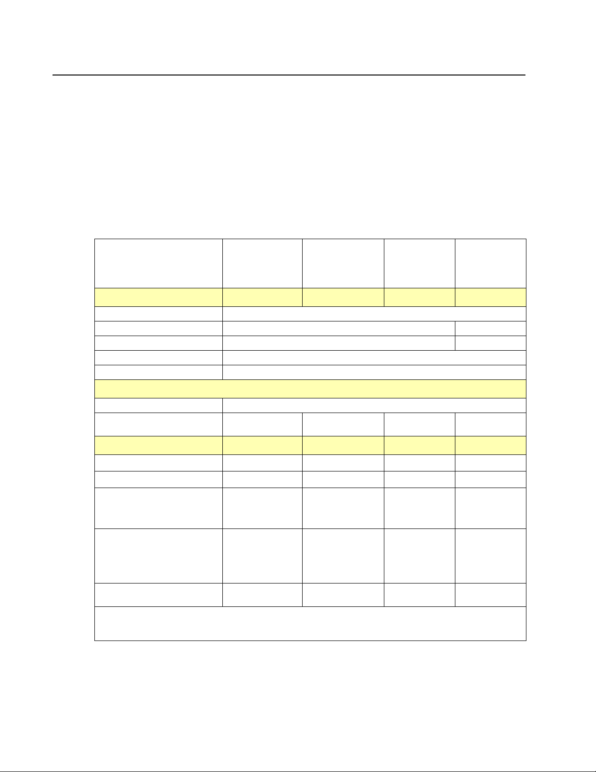
7525-xxx
✔—Supported
✘—Not supported
Options and features
Certain options are available on selected printer models only.
Available options include:
• 650-Sheet Duo Drawer—a 550-sheet drawer with a 100-sheet multipurpose feeder (MP Feeder).
• 550- Sheet Drawer - X546 only.
• Additional memory—One 128, 256, or 512MB memory card may be added.
• Flash memory card—One 64MB may be added.
• Font cards—One language card can be added.
Memory
Lexmark X543
Memory
Optional slots One slot
a
Standard DIMM sizes
Optional (DDR1) 128MB, 256MB, and 512MB 256MB, 512MB
Maximum printer memory
Flash memory 64 MB
Option Slots (single slot is available or either font or flash memory card)
Font card support 1 font card
Optional user flash memory
card sizes
Connections
USB 2.0 High Speed
Ethernet 10/100 BaseTx
USB-A
(allows direct USB printing
using approved USB flash
memory device)
Pict Bridge
(allows printing photos
directly from a compatible
camera)
128MB 256MB
b
640MB
0MB 64MB 64MB 64 MB
✔✔
✔✔
✘✔
✘✔(Only on FAX
Lexmark X544n,
X544dn, X544dtn
equipped
machines)
Lexmark
X544dw
Lexmark
X546dtn
✔ ✔
✔ ✔
✔ ✔
✔(Only on FAX
equipped
machines)
✔(Only on FAX
equipped
machines)
1-2 Service Manual
Wireless standard 802.11
b/g/n
a
Dual Inline Memory Module. An optional memory card that can be plugged into an available memory slot.
The X546 slot is filled with a 128 mb DIMM.
b
The maximum usable DDRSDRAM is standard (soldered) plus 512MB.
✘
✔ ✔
Page 25
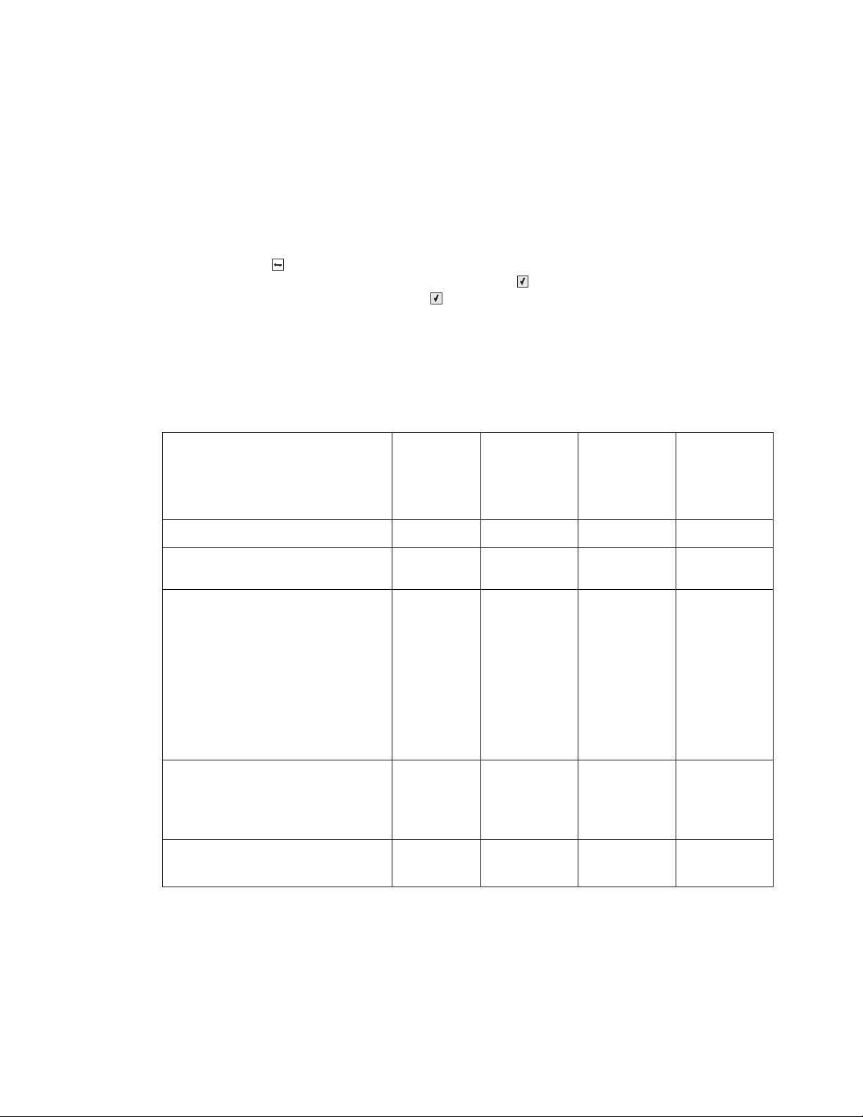
Print quality
✔—Supported
✘—Not supported
During the life of the printer, components are subject to wear based on usage. Printers continuously operating at
or near the maximum duty cycle may require service for replacement of these components to ensure highquality printing and good performance throughout the life of the printer. Replacement is recommended every
60,000 pages for the fuser and 60,000 pages for the ITU. The fuser and ITU replacement should be determined
by checking the last sheet of the Menu Settings Page. Either OK or Replace appears.
To print a Menu Settings page:
1. Press Menu ( ) on the operator panel.
2. Select Reports from the Admin Menu, and press Select ().
3. Select Menu Settings, and press Select ().
Replacement is recommended every 30,000 pages for the imaging unit.
• 4800C Q (default) full printer speed
• 1200 dpi (reduced printer speed) is supported in PS and PCL only
Connectivity (network support)
Network protocol
Lexmark
X543
Lexmark
X544n,
X544dn,
X544dtn
Lexmark
X544dw
7525-xxx
Lexmark
X546dtn
Standard Ethernet 10/100 Base T
Standard USB-B (Full speed) device
port
USB-A host ports
(In front, low/full speed) This port only
supports the following flash drives and
file types:
Supported flash drives: Lexar Jump
Drive 2.0 Pro (256/512 MB/1G
size) or SanDisk Cruzer Mini (256/
512 MB/1 G size)
Supported file
types: .pdf, .gif, .jpeg, .jpg,.bmp, .p
ng, .tiff, .tif, .pcx, .dcx
802.11n Wireless Network card
Manufacturing installs the wireless
card during the fabrication process. A
wireless card CANNOT be installed
post-manufacturing.
USB direct drive
✔✔ ✔ ✔
✔✔ ✔ ✔
✘✔ ✔ ✔
✘✘ ✔ ✘
Scan and
print (Select
formats)
Scan and print
(Select
formats)
Scan and print
(Select
formats)
Scan and print
(Select
formats)
General information 1-3
Page 26
7525-xxx
✔—Supported
✘—Not supported
Operating modes
Mode Description
Normal Factory default
Quiet Designed for customers where noise levels are a very important
Eco-Mode (Off is default): Designed for customers where the environment is a key factor.
Data streams
factor.
• Print quality is maintained at factory default level.
• Speed is reduced.
There are three options; Energy, Paper, and Energy/Paper.
• Paper • Duplex is on if Energy/Paper or Paper is selected (duplex
models only) (can be overwritten by the driver).
• Energy • Print quality is maintained.
• Power Saver is set to one minute.
• Fuser standby is off.
• The operator panel back light is off.
• Power supply energy consumption is reduced.
• Energy + Paper All of the above.
Data streams Lexmark X543
PCL 6 emulation
PostScript Level III emulation
Version 3011 of the Adobe
definition of PostScript 3 is
supported.
PDF
Supports version 1.6
PPDS
By default, the PPDS interpreter
is inactive. A user can activate the
data stream by PJL or by the
PPDS Emulation setting in the
Configuration Menu
Pict Bridge
Directimage
Devices that support Directimage
support all of the following
graphics formats: TIFF, TIF,
JPEG, JPG, GIF, PNG, BMP,
PCX, and DCX.
✔✔✔ ✔
✔✔✔ ✔
✘✔✔✔
✘✔✔✔
✘✔✔✔
✘✔✔✔
Lexmark
X544n,
X544dn,
X544dtn
Lexmark
X544dw
Lexmark
X546dtn
1-4 Service Manual
Host-Based Printing (HBP)/
Graphics Device Interface
(GDI)
Version 3 (color) uses PCL XL.
✔✔✔ ✔
Page 27
Dimensions
Models Height Width Depth Weight
Lexmark X543 291 mm (11.5 in.) 424 mm (16.7 in.) 400 mm (15.7 in.) 21 kg (46.2 lbs)
Lexmark X544n, X544dn,
X544dtn, X544dw
Lexmark X546dtn 422 mm (16.6 in.) 424 mm (16.7 in.) 416 mm (16.4 in.) 25 kg (54.9 lbs)
550-sheet Duo Drawer 133 mm (5.2 in.) 424 mm (16.7 in. 416 mm (16.4 in.) 4 kg (8.7 lb)
650-sheet Duo Drawer 133 mm (5.2 in.) 424 mm (16.7 in. 416 mm (16.4 in.) 4 kg (8.7 lb)
422 mm (16.6 in.) 424 mm (16.7 in.) 416 mm (16.4 in.) 25 kg (54.9 lbs)
Clearances
Description Clearances
X543, X544, X546
1 Rear 101.6 mm (4 in.)
2 Front 508 mm (22 in.)
3 Right side 254 mm (10in.)
4 Left side 76.2 mm (3.0 in.)
5 Top 360 mm (14 in.)*
* Add 133 mm (5.2 in.) to the top if you want to add an optional
650-sheet Duo Drawer (Lexmark X544-6 models only).
A
- This does not include the 550 sheet tray height.
A
7525-xxx
General information 1-5
Page 28

7525-xxx
Power and electrical specifications
The following table specified nominal average power requirements for the base printer configurations. All power
levels are shown in Watts (W). Maximum current is given in Amperes (A).
Printing states
Average power while printing
Continuous copy 480 W 510 W 510 W 510 W
Continuous printing simplex 480 W 540 W 540 W 540 W
Continuous printing automatic
duplex*
Average power while idle
Power Saver 22 W 24 W
Stanby 45 W 50 W 50 W 50W
Off 0 W
* Automatic duplex is not supported on the X544n.
Lexmark
Lexmark
543dn
340 W 370 W n/a 370 W
X544dw,
X544dn, and
X544dtn
23 W (dn only)
Lexmark
X544n
23 W 23W
Lexmark
X546dtn
Low-voltage models
• 100 to 127 volts (V) (100 – 110 Japan) at 50 to 60 hertz (Hz) nominal
• 90 to 137 volts (90 – 110 Japan), extreme
100 voltage models
• 100 V ac at 47 to 63 hertz (Hz) nominal
• 90 to 110 V ac, extreme
High-voltage models
• 220 to 240 V ac at 50 to 60 hertz (Hz) nominal (not available in all countries)
• 198 to 259 V ac, extreme
Notes:
• Using a 220 V ac to 110 V ac power converter with a low voltage printer is not recommended.
• Using an inverter to change DC to AC voltage (12 V to 120 V for example) is not recommended.
• All X54x MFP models will comply with the ENERGY STAR.
• All models ship with Power Saver Mode = On.
• The default timeout to Power Saver = 60 minutes (220V).
• Power Saver can be adjusted to 1-240 minutes.
• Power Saver mode cannot be disabled from the operator panel.
--
1-6 Service Manual
Page 29
Acoustics
All acoustic measurements are made in accordance with ISO 7779-1999 and reported in conformance with
ISO9296:1988-04-15.
Operating mode 1-Meter average sound pressure at 4800 CQ
Lexmark
X543
Printing (simplex mono) 46 dBA 46 dBA 47 dBA
Printing (simplex color) 47 dBA 47 dBA 48 dBA
Printing (automatic
duplex mono)
Printing (automatic
duplex color)
Copy ADF (Mono) 50 dBA 49 dBA 49 dBA
Copy ADF (Color) 50 dBA 50 dBA 50 dBA
Scan ADF (Mono) 47 dBA 45 dBA 45 dBA
Scan ADF (Color) 46 dBA 45 dBA 45 dBA
Idle Inaudible Inaudible Inaudible
Quiet Mode (simplex
mono)
Quiet Mode (simplex
duplex)
50 dBA 50 dBA 50 dBA
50 dBA 51 dBA 51 dBA
45 dBA 45 dBA 45 dBA
45 dBA 45 dBA 45 dBA
Lexmark
X544
Lexmark
X546 dtn
7525-xxx
Environment specifications
Environment Specifications
Operating
Air temperature—operating 15.6 to 32.20° C (60 to 90.0° F)
Air temperature—power off 10.0 to 43.30° C (50 to 110.0° F)
Air relative humidity Relative Humidity 8 to 80%
Wet bulb temperature—operating 22.80° C (73.0° F) maximum
Web bulb temperature—power off 26.70° C (80.10° F) maximum
Altitude 0–3,048 meters (10,000 ft.)
Atmospheric pressure 74.6 kPa
Ambient operating environment* 15.6 to 32.2° C (60 to 90° F) and 8% to 80% RH
Ship / Storage
Cartridges -40 to 43.3° C (-40 to 110.0° F)
Printer with cartridges -40 to 43.3° C (-40 to 110.0° F)
Printer without cartridges -40 to 43.3° C (-40 to 110.0° F)
Air relative humidity Relative Humidity 8 to 80%
Altitude 10,300 meters (34,000 feet)
Web bulb temperature—power off 26.70° C (80.10° F) Maximum
* In some cases performance specifications (such as paper OCF, EP cartridge usage) are specified to be
measured at an ambient condition.
General information 1-7
Page 30

7525-xxx
Media handling
Input and output sources
Sheet numbers are assuming
20 lb. xerographic paper
Standard input sources
Lexmark X543
Lexmark
X544dw,
X544dn,
X544dtn
Lexmark X544n
Lexmark
X546dtn
Standard input tray (250sheet tray)
Manual feed slot (1-sheet) 1 sheet 1 sheet 1 sheet 1 sheet
Second tray capacity (650-
sheet Duo Drawer)
Multipurpose try capacity
(650-sheet Duo Drawer)
Optional 550-sheet drawer N/A N/A 550 sheets 550 sheets
Optional input sources (maximum 1, total of all inputs is 4)
650-sheet Duo Drawer
(includes 100-sheet MP
feeder)
Multipurpose try capacity
(650-sheet Duo Drawer)
Optional third tray capacity
(550 sheets)
Maximum total input
capacity
Duplex
Type of duplex Integrated
Standard output sources (no optional output sources are available)
a
250 sheets 250 sheets 250 sheets 250 sheets
550 sheets 550 sheets 550 sheets 550 sheets
100 sheets 100 sheets 100 sheets 100 sheets
550 sheets
(or 100 sheets
in MP feeder)
100 sheets 100 sheets N/A N/A
N/A N/A N/A 550 sheets
901 901 901 1,451
duplex
550 sheets
(or 100 sheets in
MP feeder)
Integrated
duplex
550 sheets
(or 100 sheets in
MP feeder)
n/a Integrated
(tray 3)
duplex
Standard 100-sheet bin 100 100 100 100
a In the 650-sheet Duo Drawer, the 550-sheet tray and the integrated MP feeder count as two independent
input sources. The MF feeder is configured as “cassette” does not show up as Configure MP in the Paper
Menu.
1-8 Service Manual
Page 31

Duplex capability
✔—Supported
✔—Supported without size
sensing
✘—Not supported
7525-xxx
Duplex Type
Models
Lexmark X543dn
Lexmark X544n
Lexmark X544dn
Lexmark X544dw
Lexmark X544dtn
Lexmark X546dtn
Media input size specifications
Input source
A4 210 x 297mm
Automatic duplex
✔
✔
✔
✔
✔
(in the
a
250-sheet tray
Optional 650-sheet
Duo Drawer
Optional 550-sheet
drawer (model
C546dtn only)
650-sheet Duo Drawer)
MP feeder
Manual slot
Duplex
✔✔✔✔✔✔
A5a 148 x 210mm
A6 ✘✘✘
JISb B5a 182 x 257mm
Letter 8.5 x 11 in.
Legal 8.5 x 14 in.
Executivea 7.25 x 10.5 in.
Oficio (Mexico)
Folio 8.5 x 13 in.
Statementa 5.5 x 8.5 in. ✘✘✘
Universalc
148 x 210mm to
216 x 356mm
(5.8 x 8.3 in. to
8.5 x 14 in.)
76.x 127mm to
216 x 356mm
(3 x 5 in. to 8.5 x 14 in.)
a
a
✔✔✔✔✔
✔✔✔✔✔✔
✔✔✔✔✔✔
✔✔✔✔✔✔
✔✔✔✔✔
✔✔✔✔✔
✔✔✔✔✔
✔✔✔✔✔
✘
✘✘
✔
✔✘
✔✔
✔✔
✘
✘
✔
✔
✘
✘
✘
General information 1-9
Page 32

7525-xxx
✔—Supported without size
sensing
✘—Not supported
Input source
(in the
a
250-sheet tray
210mm x 279.4mm to
216mm x 356mm
(8.27 in. x 11 in. to
8.5 in. to 14 in.)
7¾ Envelopea 98 x 191mm ✘✘✘
9 Envelopea ✘✘✘
10 Envelopea 105 x 241mm
(4.12 x 9.5 in.)
DL Envelopea 110 x 220mm
(4.3 x 8.7 in.)
C5 Envelopea 162 x 229mm
(6.4 x 9 in.)
B5 Envelopea ✘✘✘✔✔✘
Other envelopea
Length: 98–432mm
(3.8–17 in.)
Width: 89–297mm (3.5–11.7
in.)
a
The MP feeder runs slower if A5, Statement, B5, A6, Executive, Statement, Universal (narrower than
210mm), or envelopes are loaded.
b
Japanese Industry Standard.
c
Although the user may select Universal paper size for these sources, not all tray guides can be adjusted to
all Universal media sizes.
✔✔✔✔✔
✘✘✘
✘✘✘
✘✘✘✔✔✘
✘✘✘
Optional 650-sheet
Duo Drawer
Optional 550-sheet
drawer (model
C546dtn only)
650-sheet Duo Drawer)
MP feeder
✔✔
✔✔
✔✔
✔✔
✔✔
Manual slot
✔
Duplex
✘
✘
✘
✘
✘
1-10 Service Manual
Page 33

Media input type specifications
✔—Supported
✘—Not supported
Input type
Plain paper ✔✔✔✔✔✔
7525-xxx
a
250-sheet tray
Optional
650-sheet
Duo Drawer
Optional 550-sheet
drawer (model
C546dtn only)
MP feeder
(in 650-sheet
Duo Drawer)
Manual feeder
Duplex
Card stock ✔✔✔✔✔
Transparency ✔✔✔✔✔✘
Recycled
Glossy ✔✔✔✔✔✔
Paper-backed labels ✔✔✔✔✔
Bond ✔✔✔✔✔✔
Envelopes
Rough envelopes ✘✘✘✔✔✘
Letterhead ✔✔✔✔✔✔
Preprinted ✔✔✔✔✔✔
Colored paper ✔✔✔✔✔✔
Light paper ✔✔✔✔✔✔
Heavy paper ✔✔✔✔✔✔
Rough or cotton ✔✔✔✔✔✔
Custom type <x>
a
For MP feeder and manual feeders, the Default Source Menu displays Manual Paper and Manual Env. Select
Manual Env. for envelopes or when the type in Custom Type <x> is an envelope. For other types, use
Manual Paper.
b
The duplex unit supports this media type as long as the customer has selected the custom type from those
types the duplex unit supports.
b
✔✔✔✔✔✔
✘✘✘✔✔✘
b
✔✔✔✔✔✔
✘
Media output size and type
There is a single 100-sheet output bin available for this printer and no additional output options.
General information 1-11
Page 34

7525-xxx
Weight ranges for each media type
Material Type Weight Select
2, 5, 7, 8
Paper
Specialty papers Gloss Book 88 to 176 g/m
Card stock—upper
limit (grain long)
Card Stock—upper
limit (grain short)
Transparency
Labels—upper limit Paper 131 g/m
Envelopes
(Multipurpose
feeder or manual
slot only)
1
For 60 to 176 g/m2 paper, grain long fibers are recommended.
2
Paper less than 75 g/m2 (20 lb) must be printed with Paper Type set to Light Paper.
3
100% cotton content maximum weight is 24 lb bond.
4
28 lb bond envelopes are limited to 25% cotton content.
5
The duplex unit supports paper weights between 60–105 g/m2 (16–28 pound) grain long bond. The duplex
unit does not support card stock, transparencies, envelopes, and labels.
6
Lexmark transparency part numbers 12A8240, and 12A8241 are supported from the standard tray, manual
slot and the multipurpose feeder.
7
Paper 90 to 104.9 g/m2 (23.9 to 27.8 lb) must be printed with Paper Type set to Heavy Paper.
8
Paper 105 to 176 g/m2 (27.9 to 47 lb) must be printed with Paper Type set to Cardstock.
Xerographic or
business paper
Gloss Cover 162 to 176 g/m
Index Bristol 120 g/m2 (67 lb)
1
Tag 120 g/m
Cover 135 g/m
Index Bristol 163 g/m2 (90 lb)
1
Tag 163 g/m
Cover 176 g/m
6
Laser printer 170 to 180 g/m2 (45 to 48 lb bond)
Sulfite, wood-free or
up to 100% cotton
bond
60 to 74. 9 g/m2 grain long
(16 to 19.9 lb bond)
75 to 89.9 g/m
2, 5
2
grain long
(20 to 23.8 lb bond)
2
90. to 104.9 g/m
grain long
(23.9 to 27.8 lb bond)
2
105 to 176 g/m
(27.9 to 47 lb bond)
2
2
2
2
2
60 to 105 g/m
grain long
7
2
grain long (60 to 120 lb book)
2
grain long (60 to 65 lb cover)
(74 lb)
(50 lb)
(100 lb)
(65 lb)
(35 lb bond)
2
to 28 lb bond)
Light Paper
Plain Paper
Heavy Paper
Card stock
3, 4
1-12 Service Manual
Page 35

Media guidelines
Paper characteristics
The following paper characteristics affect print quality and reliability. Consider these characteristics when
evaluating new paper stock.
• Weight—The printer can automatically feed paper weights from 60 to 176 g/m
long. Paper lighter than 75 g/m
performance, use 80 g/m
in.), we recommend 90 g/m
• Curl—Curl is the tendency for paper to curl at its edges. Excessive curl can cause paper feeding problems.
Curl can occur after the paper passes through the printer, where it is exposed to high temperatures.
Storing paper unwrapped in hot, humid, cold, or dry conditions, even in the trays, can contribute to paper
curling prior to printing and can cause feeding problems.
• Smoothness—Paper smoothness directly affects print quality. If paper is too rough, toner cannot fuse to it
properly. If paper is too smooth, it can cause paper feeding or print quality issues. Always use paper
between 100 and 300 Sheffield points; however, smoothness between 150 and 200 Sheffield points
produces the best print quality.
• Moisture content—The amount of moisture in paper affects both print quality and the ability of the printer
to feed the paper correctly. Leave paper in its original wrapper until it is time to use it. This limits the
exposure of paper to moisture changes that can degrade its performance. Condition paper before printing
by storing it in its original wrapper in the same environment as the printer for 24 to48 hours before printing.
Extend the time several days if the storage or transportation environment is very different from the printer
environment. Thick paper may also require a longer conditioning period.
• Grain direction—Grain refers to the alignment of the paper fibers in a sheet of paper. Grain is either grain
long, running the length of the paper, or grain short, running the width of the paper. For 60 to 176 g/m
to 47 lb bond) paper, use grain long fibers.
• Fiber content—Most high-quality xerographic paper is made from 100% chemically treated pulped wood.
This content provides the paper with a high degree of stability resulting in fewer paper feeding problems
and better print quality. Paper containing fibers such as cotton possesses characteristics that can
negatively affect paper handling.
7525-xxx
2
2
(20 lb) might not be stiff enough to feed properly, causing jams. For best
2
(21 lb bond) grain long paper. For paper smaller than 182 x 257 mm (7.2 x 10.1
2
or heavier paper.
(16 to 47 lb bond) grain
2
(16
Unacceptable paper
The following paper types are not recommended for use with the printer:
• Preprinted papers with chemicals that may contaminate the printer
• Preprinted papers that can be affected by the temperature in the printer fuser
• Coated papers (erasable bond), synthetic papers, thermal papers
• Rough-edged, rough or heavily textured surface papers, or curled papers
• Recycled papers containing more than 25% post-consumer waste that do not meet DIN 19 309, and
weighing more than 80 g/m
• Paper weighing less than 80 g/m
2
2
(21 lb)
• Multiple-part forms or documents
General information 1-13
Page 36

7525-xxx
Selecting paper
Using appropriate paper prevents jams and helps ensure trouble-free printing. To help avoid jams and poor print
quality:
• Always use new, undamaged paper.
• Before loading paper, know the recommended print side of the paper. This information is usually indicated
on the paper package.
• Do not use paper that has been cut or trimmed by hand.
• Do not mix paper sizes, types, or weights in the same source; mixing results in jams.
• Do not use coated papers unless they are specifically designed for electrophotographic printing.
Selecting preprinted forms and letterhead
Use these guidelines when selecting preprinted forms and letterhead:
• Use grain long for 60 to 176 g/m
2
weight paper.
• Use only forms and letterhead printed using an offset lithographic or engraved printing process.
• Avoid papers with rough or heavily textured surfaces.
Use papers printed with heat-resistant inks designed for use in xerographic copiers. The ink must be able to
withstand temperatures up to 200°C (392°F) without melting or releasing hazardous emissions. Use inks that
are not affected by the resin in toner. Inks that are oxidation-set or oil-based generally meet these requirements;
latex inks might not. When in doubt, contact the paper supplier.
Preprinted papers such as letterhead must be able to withstand temperatures up to 200°C (392°F) without
melting or releasing hazardous emissions.
Storing paper
Use these paper storage guidelines to help avoid jams and uneven print quality:
• For best results, store paper where the temperature is 21°C (70°F) and the relative humidity is 40%. Most
label manufacturers recommend printing in a temperature range of 18 to 24°C (65 to 75°F) with relative
humidity between 40 and 60%.
• Store paper in cartons when possible, on a pallet or shelf, rather than on the floor.
• Store individual packages on a flat surface.
• Do not store anything on top of individual paper packages.
Using recycled paper and other office papers
As an environmentally conscious company, Lexmark supports the use of recycled office paper produced
specifically for use in laser (electrophotographic) printers. In 1998, Lexmark presented to the US government a
study demonstrating that recycled paper produced by major mills in the US fed as well as non-recycled paper.
However, no blanket statement can be made that all recycled paper will feed well. Lexmark consistently tests its
printers with recycled paper (20–100% post-consumer waste) and a variety of test paper from around the world,
using chamber tests for different temperature and humidity conditions. Lexmark has found no reason to
discourage the use of today's recycled office papers, but generally the following property guidelines apply to
recycled paper.
• Low moisture content (4–5%)
• Suitable smoothness (100–200 Sheffield units, or 140–350 Bendtsen units, European)
Note: Some much smoother papers (such as premium 24 lb laser papers, 50–90 Sheffield units) and
much rougher papers (such as premium cotton papers, 200–300 Sheffield units) have been engineered to
work very well in laser printers, despite surface texture. Before using these types of paper, consult your
paper supplier.
• Suitable sheet-to-sheet coefficient of friction (0.4–0.6)
• Sufficient bending resistance in the direction of feed
1-14 Service Manual
Page 37

7525-xxx
Recycled paper, paper of lower weight (<60 g/m
2
[16 lb bond]) and/or lower caliper (<3.8 mils [0.1 mm]), and
paper that is cut grain-short for portrait (or short-edge) fed printers may have lower bending resistance than is
required for reliable paper feeding. Before using these types of paper for laser (electrophotographic) printing,
consult your paper supplier. Remember that these are general guidelines only and that paper meeting these
guidelines may still cause paper feeding problems in any laser printer (for example, if the paper curls excessively
under normal printing conditions).
General information 1-15
Page 38

7525-xxx
Digital imaging specifications
General specifications
ADF Scan speed
Simplex ADF - Up to 5 ppm
Duplex ADF - Up to 5 ppm (page sides)
ADF Document handling
ADF input capacity - 50 sheets.
ADF output capacity - 50 sheets.
ADF document width - 4.9” (125mm) to 8.5”(216mm)
ADF document length - 5” (127mm) to 14.0”(356mm)
Resolution and color depth
Resolution - 1200 dpi optical
•
• CDD 1200 dpi, and 600 dpi. Selectable through electronics
• Color depth - 48 bit RGB output. 16 bit / channel
Flatbed document specifications
Document size- Up to A4 and letter
•
4.5” x 5.5” to 8.5”x11” (SEF)
Flatbed speed
3 seconds to scan, 3 seconds to return.
Scanner operating environments
Temperature - 10C to 35C
•
• Humidity - 15% RH to 85% RH
Storage environments
Temperature - -20C to 43C
•
• Humidity - 5%RH to 95% RH
Tilt
This device should operate within the stated parameters when it is level within 10mm from front to back and
10mm side to side.
1-16 Service Manual
Page 39

Scan and copy specific specifications
Scan Resolutions
Optical - 600 dpi (Local Twain only)
•
• Enhanced (vial Lexmark Scan Center) - 1200 X 1200 dpi, 2400 X 2400 dpi, 4800 X 4800 dpi, 9600 X 9600
dpi, 19200 X 19200 dpi
Output resolutions
•
Mono - 600 X 600 dpi
• Color - 300 X 300 dpi
Duplex scan
Duplex and copy is available only on X544, and X546 series machines.
Scan file output formats
TIFF
•
• JPEG
• PDF
7525-xxx
Supported compressions
•
PDF - (1 bit,- JBIG2 CCIT G4, Flate), (8/24 bit - Flate JPEG)
• TIFF - (1 bit - CCITT G4), (8/24 bit - Packbits, LZW)
• JPG - (8/24 bit-JPG)
Supported scan destinations
•
Temporary profile from a user’s PC
• Scan to PC via network TWAIN
• Scan to PC using Web applet
• Scan to E-Mail
• Scan to USB (X544 models only)
• Lexmark Scan Center
Multiple copies
999 copies maximum
Reduce / Enlarge
-25% to 400%
General information 1-17
Page 40

7525-xxx
Fax specifications
Phone network connectivity
Phone networks types supported PSTN or analog PABX (RJ-11)
ITU COMPATIBILITY
Standard Resolution
Fine
Superfine
Ultrafine
Coding
Modem speed V.34 2,400-33,600 BPS,
Compression
Error correction ITU T.30
Line interface selection
Modular Plug
Out Band Signal Level
Input Level Range
Ring Detection
Group 3/ECM
8 x 3.85 pels/mm (200X100dpi) (204x98)
8 x 7.7 pels/mm (200X200dpi) (204x196)
11.8 x 11.8 pels/mm(300x300 dpi) (204x391)
15.7 x 15.7 pels/mm (400x400 dpi) (408x391)
ITU T.4 and T.6(MH, MR, MMR, JPEG)
V.17 7,200-14,400 BPS,
V.27 2,400-4,800 BPS,
V.29 7,200-9,600 BPS
MH, MR, MMR, JPEG
Dual RJ-11C
Guaranteed North American and Europe PTT standard
-16dBm ~ -59dBm
Complies with all regulatory requirements
Fax resolutions
Receive 200x100 dpi, 200x200 dpi, 300x300 dpi,
Send 200x100dpi, 200x200 dpi, 300x300 dpi
400x400 dpi, 204x98 dpi, 204x196 dpi,
204x391 dpi, 408x391 dpi
Miscellaneous FAX specifications
Fax memory 4 MB Flash (More than 320 pages based on ITU chart #1)
Speed dial Yes. 99 entries
Transmission Approximately 3 seconds per page
Color fax Yes
Fax from PC Yes. Suppor ted using PostScript driver for both local and
Caller ID Yes
Junk FAX blocking Yes - based on caller ID and remote station ID
Tone/Pulse Tone: Default, Pulse: Yes
Fax forward Yes
Broadcasting Yes. 12 destinations
External phone interface Yes
Manual mode Yes
Fax shortcuts Yes.
Fax content Text, text/photo, photo
Fax preservation Yes
Halftoning Yes
User selectable parameters are stored in NVRAM.
network attach modes.
1-18 Service Manual
Page 41

Tools required for service
Flat-blade screwdrivers, various sizes
#1 Phillips screwdriver, magnetic
#2 Phillips screwdriver, magnetic
#2 Phillips screwdriver, magnetic short-blade
7/32 inch (5.5 mm) open-end wrench
7.0 mm nut driver
Needlenose pliers
Diagonal side cutters
Spring hook
Feeler gauges
Analog or digital multimeter
Parallel wrap plug 1319128
Flash light (optional)
7525-xxx
General information 1-19
Page 42

7525-xxx
Acronyms.
ac Alternating Current
ACM Autocompensator Mechanism (or paper feed)
ADF Automatic document feeder
AFE Analog front end
AIO All-In-One
APS Automatic Paper Size
ASIC Application Specific Integrated Circuit
BLDC Brushless DC Motor
BOR Black Only Retract
BUD Belt up down
CCyan
CCD Charge-Couple Device
CCFL Cold Cathode Fluorescent Lamp
CCW Counter clockwise
CDB Command Descriptor Blocks
CMYK Cyan yellow magenta black
CPU Central processing unit
CRC Cyclic redundancy check
CRU Customer Replaceable Unit
CSU Customer Setup
CW Clockwise
DBCS Double byte character set
dc Direct Current
DIMM Dual Inline Memory Module
DLE Downloadable emulator
DRAM Dynamic random access memory
DVM Digital multimeter
ECC Error correcting code
ECM Error correction mode
EDO Enhanced Data Out
EEPROM Electrical Erasable Programmable Read-Only Memory
ENA External Network Adapter
EOL End of line
EP Electrophotographic process
EPROM Erasable programmable read-only memory
ESD Electrostatic Discharge
FB Flatbed
FD Facedown
FRU Field replaceable unit
FU Face up
GB Gigabyte
GFI Ground Fault Interrupter
GHz Gigahertz
HBP Host Based Printing
HCF High-capacity feeder
HCIT High-capacity Input Tray
HCOF High-Capacity Output Finisher
HCPF High-capacity feeder
HTML Hypertext markup language
HV High Voltage
HVPS High voltage power supply
1-20 Service Manual
Page 43

HVU High voltage unit
Hz Hertz
INTL International
ITC Internal Tray Card
ITU Image Transfer Unit
KBlack (Key)
LAN Local area network
LASER Light amplification by stimulated emission of radiation
LCD Liquid crystal display
LCM Liquid Crystal Module
LD Laser Diode
LED Light emitting diode
LEF Long edge feed
LES Lexmark Embedded Solution (applications)
LSU Laser Scanning Unit
LV Low Voltage
LVPS Low voltage power supply
M Magenta
MB Megabyte
MDC Motor Driver Control
MFD Multifunction Device
MFP Multifunction Printer
MH Message handling
MIF Motor interface
mm Millimeter
MMR Modified modified read
MPF Multipurpose feeder
MR Modem ready
MROM Masked Read Only Memory
MS Microswitch
NAND NAND (usage: NAND gate)
NVM Nonvolatile Memory
NVRAM Nonvolatile Random Access Memory
OCF Operator correctable failure
OCR Oil coating roll
OEM Original Equipment Manufacturer
OHP Overhead projector
OPC Optical photo conductor
OPT Optical Sensor
PC Photoconductor
PDF Portable Document Format
PICS Problem isolation charts
PIN Personal identification number
PIXEL Picture element
PJL Printer Job Language
POR Power-on reset
POST Power-on self test
PPDS Personal Printer Data Stream
ppm Pages per minute
PQET Print Quality Enhancement Technology
PRC Peoples' Republic of China
PSC Parallel Synchronous Communications
PSD Position Sensing Device
PSO Participating Standards Organization
7525-xxx
General information 1-21
Page 44

7525-xxx
PWM Pulse Width Modulation
RAM Random access memory
RFID Radio frequency identification
RH Relative humidity
RIP Raster image processor
ROM Read-only memory
ROS Read-only storage
RPM Revolutions Per Minute
SCC Scanner Control Card
SDRAM Synchronous Dynamic Random Access Memory
SEF Short edge feed
SIMM Single Inline Memory Module
SOL Solenoid
SOS Start of scan
SRAM Static random access memory
TAR Toner Add Roll
TPS Toner Patch Sensing
TTM Tandem Tray Module
TVOC Total Volatile Organic Compound
UAT Universally Adjustable Tray
UPR Used Parts Return
USB Universal Serial Bus
VVolts
V ac Volts alternating current
V dc Volts direct current
VOIP Voice over internet protocol
VOM Volt Ohmmeter
VTB Vacuum Transport Belt
XPS XML Paper Specification
YYellow
1-22 Service Manual
Page 45

2. Diagnostic information
CAUTION
Unplug the power cord from the electrical outlet before you connect or disconnect any cable
or electronic board or assembly for personal safety and to prevent damage to the printer.
Disconnect any connections between the printer and PCs/peripherals.
Start
Begin here to locate the service error code, user status message, user error message, symptom table, service
checks, and diagnostic aids in this chapter to determine the corrective action necessary to repair a
malfunctioning printer. They will lead you to solutions or service checks, including use of various tests.
• Does the POR stop? Check the “POR (Power-On Reset) sequence” on page 2-2
• Do you have a symptom, rather than an error message? Locate your symptom, and take the appropriate
action:
– “Printer symptom table” on page 2-3
– “Scan / fax / copy symptom table” on page 2-4
• If you have an error message or user message, check the following:
– “Service error messages” on page 2-15
– “User status and attendance messages” on page 2-6
– “Paper Jam messages” on page 2-13
– “Service checks” on page 2-31 for individual error messages
• Additional information can be found at the following locations:
– “Operator panel and menus” on page 2-2
– “POR (Power-On Reset) sequence” on page 2-2
– “Print engine theory” on page 3-57
7525-xxx
Diagnostic information 2-1
Page 46

7525-xxx
POR (Power-On Reset) sequence
The following is an example of the events that occur during the POR sequence for the base machine with no
paper-handling options installed.
When you turn the printer on, it performs a Power-On Self Test. Check for correct POST functioning of the base
printer by observing the following:
1. The LED turns on.
2. The main fan turns on.
3. The operator panel turns on.
4. A partial row of pixels appears.
5. The operator panel display clears.
6. Another row of pixels appears.
7. The operator panel display clears again.
8. The operator panel displays system information. For example:
*256MB 500Mhz
9. The fuser lamp turns on. The fuser takes longer to warm up from a cold start than a warm start.
10. The operator panel LED starts blinking.
The following errors or messages may appear:
• Close Door or Insert Cartridge display if the upper front cover is open or the print cartridge is missing.
• Any cartridge errors, such as Defective Cartridge or Missing Cartridge.
11. Ready appears on the display.
12. The main drive motor turns on.
13. The EP drive assembly drives the developer shaft located in the toner cartridge.
14. The exit rollers turn.
15. The printer calibrates.
2-2 Service Manual
Page 47

Symptom tables
Printer symptom table
Symptom Action
Dead printer Go to “Dead printer service check” on page 2-35.
Operator panel—one or more buttons do
not work.
Operator panel—display is blank. Printer
sounds five beeps.
Operator panel—display is blank. Go to “Operator panel display blank, five beeps” on
Operator panel continuously displays all
diamonds and does not complete POST.
Pages print blank after replacing the
controller board.
Tray linking does not work. • Check that the same size and type of paper are in each tray.
Unexpected page breaks occur • Increase the Print Timeout value on the operator panel
Multipurpose feeder has constant misfeeds
or jams.
Page that jammed does not reprint after
you clear the jam.
Printing speed reduced for more than 10
pages. May happen after a service call.
Pages print blank after replacing the
controller board.
7525-xxx
Go to “One or more operator panel buttons fail” on
page 2-42.
Go to “Operator panel display blank, five beeps” on
page 2-42.
page 2-42.
Go to “Operator panel display blank, five beeps” on
page 2-42.
When replacing the controller board, verify the cable from the
high-voltage power supply is seated properly. The cable may
have come loose from the HVPS.
Warning: A blank page that should have toner on it could be an
indication that toner is applied to the ITU belt but not transferred.
Therefore the toner goes into the ITU cleaner which cannot
process massive amounts of toner. It is important to prevent
extensive blank pages from being processed if they should have
toner on them.
• Check the location of the paper guides.
• The multipurpose feeder does not automatically sense the
paper size. You must set the size from the Paper Size/Type
menu.
• Print a menu settings page, compare the settings for each
tray, and adjust on the operator panel, if necessary.
(Settings–>General Settings–>Timeouts–>Print Timeout).
• Remove and flex the paper in the tray. Reload the paper, and
try printing.
• Turn the paper over inside the tray.
• Make sure the feeder is properly installed.
• Make sure the paper is loaded correctly in the tray.
• Make sure the paper is not damaged.
• Make sure the paper meets specifications. See “Media
input type specifications” on page 1-11.
• Make sure the paper guides are positioned correctly for the
paper size loaded in the tray.
Jam Recovery may be set to Off. Change the setting to Auto or
On on the operator panel (Settings–>General settings–>Print
Recovery–>Jam Recovery.)
Check the narrow media sensor cable is correctly connected at
the sensor, and the cable is correctly connected to JBIN1 on the
controller board.
When replacing the controller board, verify the cable from the
high-voltage power supply is seated properly. The cable may
have come loose from the HVPS.
Warning: A blank page that should have toner on it could be an
indication that toner is applied to the ITU belt but not transferred.
Therefore the toner goes into the ITU cleaner which cannot
process massive amounts of toner. It is important to prevent
extensive blank pages from being processed if they should have
toner on them.
Diagnostic information 2-3
Page 48

7525-xxx
Symptom Action
Unexpected page breaks occur • Increase the Print Timeout value on the operator panel
Scan / fax / copy symptom table
Symptom Action
840.xx scanner error Go to “840.xx service check” on page 2-63.
ADF won’t duplex (Duplex ADF only) Go to “ADF Duplex service check” on page 2-70.
ADF skew Go to “ADF feed errors service check” on page 2-69.
Multiple pages feed into ADF
Documents wont feed into ADF
Scanner makes buzzing noise on startup or
during a scan.
Document feeds, but jams in ADF. Go to “ADF paper jam service check” on page 2-68.
Black streaks on scans Go to “ADF streak service check” on page 2-67.
Blank page Go to “Black or blank page copy service check” on
Black page
No dial tone Go to “Modem / fax card service check” on page 2-71.
Machine dials a number but fails to make a
connection with another fax machine.
Incoming fax has blank spaces or poor
quality.
Invalid fax partition, or fax partition too
small.
Some words on an incoming fax are
stretched.
Faxes fail to transmit. Go to “Fax transmission service check” on page 2-72.
Fax reception fails. Go to “Fax reception service check” on page 2-74.
Rattling noise coming from the ADF unit Inspect the ADF separator roll and ADF separator pad for proper
(Settings–>General Settings–>Timeouts–>Print Timeout.)
Go to “Flatbed home position service check” on page 2-66.
page 2-65.
The other fax machine may be turned off. Ask the fax recipient to
check their machine.
1. The sending fax machine may be faulty.
2. The sending fax machine may have a dirty document glass.
3. A noisy phone line can cause errors.
4. Check the MFP print quality by making a copy.
5. The print cartridge may be empty. Replace as necessary.
See “Format Fax Storage” on page 3-34.
The sending fax machine had a temporary jam.
installation. If needed, remove the separator pad and separator
roll and reinstall them. See “ADF separator pad” on page 4-87
and “ADF separator roll assembly” on page 4-88. for removal
instructions.
2-4 Service Manual
Page 49

Print quality symptom table
Symptom Action
Background Go to “Print quality—background” on page 2-49.
Blank page Go to “Print quality—blank page” on page 2-50.
Blurred or fuzzy print Go to “Print quality—blurred or fuzzy print” on page 2-52.
Half-color page Go to “Print quality—half-color page” on page 2-52.
Horizontal banding Go to “Print quality—horizontal banding” on page 2-52.
Horizontal line Go to “Print quality—horizontal line” on page 2-53.
Insufficient fusing Go to “Print quality—insufficient fusing” on page 2-53.
Missing image at edge Go to “Print quality—missing image at edge” on page 2-53.
Mottle (2–5mm speckles) Go to “Print quality—mottle (2–5mm speckles)” on
Narrow vertical line Go to “Print quality—narrow vertical line” on page 2-54.
Random marks Go to “Print quality—random marks” on page 2-54.
Residual image Go to “Print quality—residual image” on page 2-55.
Solid color page Go to “Print quality—solid color page” on page 2-56.
Vertical banding Go to “Print quality—vertical banding” on page 2-56.
Color problems Go to “Color theory” on page 3-71.
Light print on solids Go to “Media guidelines” on page 1-13.
7525-xxx
page 2-53.
Diagnostic information 2-5
Page 50

7525-xxx
Error codes and messages
User status and attendance messages
User status and attendance messages
User primary message Explanation
Busy Wait for the message to clear.
Calibrating The printer is performing a color adjustment.
Close Door Message clears when upper and lower doors are closed.
Check Config ID The printer configuration ID is invalid.
Check Model Name Message clears when a valid model name is set.
Check Serial Num Message clears when a valid serial number is set.
<color> Low Replace the toner cartridge, and then wait for the message to clear.
Defragmenting Flash
DO NOT POWER OFF
Flushing buffer Wait for the message to clear.
Formatting Flash
DO NOT POWER OFF
Hex Trace This message appears between status messages and warnings. Wait for the
Imaging Kit Replace the imaging kit, and then press Select ( ) to clear the message and
Insert Tray <x> This message is displayed when the printer requests the user to insert tray x before it
No Analog Phone Line
Memory Full, cannot
send faxes
Insert Duplex Page in
Tray <x>
Install Tray <x> or
Cancel job
Load <source> <custom
string>
The printer is performing the defragmentation operation of flash memory. Wait for the
message to clear.
Warning: Do not turn the printer off while this message appears on the display.
Wait for the message to appear.
Warning: Do not turn the printer off while this message appears on the display.
message to clear.
continue printing.
can continue printing the job. The printer needs to pick media from the missing tray or
the trays below it.
Tray x=Tray 1, Tray 2, Tray 3
Note: This message displays when refilling the trays during a job. Before filling tray a
tray, take the printer offline by pressing Stop , and wait for pages to stop feeding
into the output bin.
The following actions can be taken:
• Insert the requested tray.
• Cancel the current job
An analog line is not detected as being plugged into the modem. If the device is in
Analog mode, this has a source of Fax. If the device is in Fax Server mode, and the
'Enable analog receive' Fax Server setting is set to 'On', this has a source of Fax
Receive. If the device is in Fax Server mode and the 'Enable analog receive' Fax
Server setting is set to 'Off', then this IR is not generated.
After a start, there is no memory to do the fax job. Attempted fax is cancelled.
Reload printed page in tray <x>. Cancel Job appears if the job can be cancelled.
Printer detects that tray <x> is missing, where x is 1 or 2. This message appears if the
job was begun, but the paper has not yet been retrieved. The tray is no longer
detected. Replace the indicated tray.
Printer does not detect media meeting the description <custom string> in <source>,
where <source> is Tray 1, Tray 2, Tray 3, Multi-Page Feeder (MP feeder), or Envelope
Feeder.
• Load the input source with the correct type and size media.
• Cancel the current job.
2-6 Service Manual
Page 51

7525-xxx
User status and attendance messages (continued)
User primary message Explanation
Load <source>
<custom type>
Load <source>
<size>
Load <source>
<type> <size>
Load single sheet
<custom type>
Load single sheet
<custom string>
Load single sheet
<size>
Load single sheet
<type> <size>
PJL ST Message Try one or more of the following:
Power Saver The printer is saving power while it waits for the next print job.
Programming Code The printer is receiving a file that is a code update. Wait for the message to clear.
Programming Flash Fonts and macros are being written to flash. Wait for the message to clear.
Ready The printer is ready to print.
Printer does not detect media meeting the description <custom type> in <source>,
where <source> is Tray 1 or Tray 2, Tray 3.
• Load the input source with the correct type and size media.
• Cancel the current job.
Printer does not detect media meeting the size requested in the source indicated.
• Load the input source with the correct type and size media.
• Cancel the current job.
Printer does not detect media meeting the size or type requested in the source
indicated.
• Load the input source with the correct type and size media.
• Cancel the current job.
Printer does not detect media meeting the description <custom type> in the single
sheet feeder (manual feeder).
The following actions can be taken:
• Load paper, and the job continues.
•press Select ( ), and choose an alternate source for media.
• Cancel the current job.
Printer does not detect media meeting the description <custom string> in the single
sheet feeder (manual feeder).
The following actions can be taken:
• Load paper and the job continues.
•press Select ( ), and choose an alternate source for media.
• Cancel the current job.
Printer does not detect media meeting the description <size> in the single sheet
feeder (manual feeder).
The following actions can be taken:
• Load paper and the job continues.
•press Select ( ), and choose an alternate source for media.
• Cancel the current job.
Printer does not detect media meeting the description <type> and <size> in the single
sheet feeder (manual feeder).
The following actions can be taken:
• Load paper and the job continues.
•press Select ( ), and choose an alternate source for media.
• Cancel the current job.
•press Select (
ait for the message to clear.
• W
• Send a job to print.
•Press Select ( ) to warm the printer to normal operating temperature.
Afterwards, Ready appears.
Warning—Potential Damage: Do not turn the printer off while this message appears
on the display.
) to clear the message, and continue printing.
Diagnostic information 2-7
Page 52

7525-xxx
User status and attendance messages (continued)
User primary message Explanation
Remove Paper ADF
Remove Paper
Standard Bin
Remove Packaging
Material
Unplug and Change
Mode
Replace Black Imaging
Unit
Replace Color Imaging
Unit
Replace <color>
Cartridge
Std Bin Full The following actions can be taken:
Tray <x> Empty The following actions can be taken:
Tray <x> Low Load the paper tray or other source with the correct paper type and size.
Tray <x> Missing Insert the specified tray into the printer.
Unplug and Change
Mode
Unsupported Mode Camera is not in a proper mode to use the Pict Bridge feature. Unplug the camera
Unsupported USB
Device, Please Remove
Unsupported USB Hub,
please remove
Waiting The printer has received data to print, but is waiting for an End-of-job command, a
Waiting, too many
events
Waste Toner Box The waste toner bottle is nearly full. Press Select ( ) to clear the message and
30.xx <color> Toner
Cart Missing
This posts when there is paper detected in the ADF upon POR or when the cover is
closed (or any other situation that re-inits the scanner). Message clears when paper
is removed.
The standard output bin is full or nearly full. Remove the media from the bin.
Packaging material is detected by the printer. Remove the packaging material and
press Continue.
Camera is not in a proper mode to use the PictBridge feature. Unplug the camera
cable to the printer, and change the camera mode.
Replace the Black Imaging Unit.
Replace the Color Imaging Unit.
Replace the toner cartridge of the indicated color. The printer continues after the
toner door is closed.
• Remove paper from the standard exit bin to clear the message and continue
printing.
•Press Select ( ) to clear the message and continue printing.
• Load the paper tray or other source with the correct paper type and size.
•Press Stop ( ) and then press Select ( ) to cancel the current job.
Camera is not in a proper mode to use the PictBridge feature. Unplug the camera
cable to the printer, and change the camera mode.
cable to the printer and change the camera mode.
Remove the unrecognized device from the USB port on the front of the printer.
Remove the unrecognized USB hub/device from the USB port on the front of the
printer.
Form Feed command, or additional data.
The following actions can be taken:
•Press Select ( ) to print the contents of the buffer.
• Cancel the current print job.
Wait for the message to clear.
Warning—Potential Damage: Do not turn the printer off while this message appears
on the display.
continue printing.
The specified toner cartridge is missing. Re-install the missing toner cartridge to clear
the message, and then continue printing. If the message recurs remove and re-install
the cartridge. Listen for the click to ensure the cartridge is installed properly. Close
the front cover.
2-8 Service Manual
Page 53

User status and attendance messages (continued)
User primary message Explanation
31.xx Defective <color>
cartridge
31.xx Defective Imaging
Kit.
32.xx Replace
unsupported <color>
Cartridge
34 Short Paper • press Select (
35 RES Save Off
Deficient Memory
37 Insufficient Collation
Area
The specified cartridge is defective. Try one of the following:
• Open and close the top cover.
• Remove and re-install the cartridge(s). Listen for the click to ensure the cartridge
is installed properly.
• Turn the printer power off and turn the printer power on.
If the message persists, replace the cartridge with a new one, and close the front
cover.
Defective imaging kit. Try one or more of the following:
• Open and close the top cover.
• Remove and re-install the cartridge(s). Listen for the click to ensure the cartridge
is installed properly.
• Turn the printer power off, and then turn the printer power on.
If the message persists, determine if the imaging kit counter is greater than 15,000
cycles. It it is, then replace the entire kit. See “Imaging unit (IU) removal” on
page 4-40. If the counter is below 250,000 cycles, replace only the photoconductors.
Remove the specified cartridge, replace with a supported cartridge, and close the
front cover.
) to clear the message and continue printing.
The printer does not automatically reprint the page that prompted the message.
• Check tray length and width guides to ensure paper is properly fitted in the tray.
• Make sure the print job is requesting the correct size of paper.
• Adjust the Paper Size setting for the size paper you are using.
If MP Feeder Size is set to Universal, make sure the paper is large enough for the
formatted data.
• Cancel the current job.
This message displays when the printer lacks sufficient memory to enable Resource
Save. This message usually indicates the user has allocated too much memory for
one or more of the printer link buffers; however, modification of other printer settings
which affect the amount of available memory may also create this condition. If
restoration of Resource Save is required after this message is received, the customer
should install additional memory or set each link buffer to Auto. Once all link buffers
are returned to Auto, you should exit the menu to activate the link buffer changes.
Once the printer returns to the Ready state, you can enable Resource Save and go
back and modify the link buffers again. Note the reduction of available memory to the
link buffers when Resource Save has been enabled, and compare it to the memory
available when Resource Save is disabled.
•press
• Install additional memory.
This message is displayed when the printer memory used to store pages is too full to
collate the print job.
The following actions can be taken:
•press Select ( ) to print the portion of the job already stored, and begin collating
•press Menus ( ) to access the Busy/Waiting Menu.
Note: Menu Lockout does NOT prevent access to the Busy/Waiting Menu.
Select ( ) to disable Resource Save and continue printing.
To enable Resource Save after you get this message:
- Make sure the link buffers are set to Auto, then exit the menus to activate the
link buffer changes.
- When Ready is displayed, enable Resource Save.
the rest of the job.
The following functions are available.
- Cancel Job
7525-xxx
Diagnostic information 2-9
Page 54

7525-xxx
User status and attendance messages (continued)
User primary message Explanation
37 Insufficient memory
for flash defragment
operation
38 Memory Full This message is displayed when the printer is processing an incoming job and there
39 Complex Page This message is displayed when a page is too complex to print.
40 <color> Invalid Refill,
change cartridge
50 PPDS Font Error This error only occurs when a printer is formatting PPDS print data.
51 Defective Flash
Detected
This message is displayed when insufficient printer memory is available to perform
Flash Memory Defragment operation.
This message appears prior to the actual start of the defragment operation.
Select ( ) to stop the defragment operation.
press
To perform the defragment operation, you can:
• Delete fonts, macros, and other data in RAM.
• Install additional printer memory.
•press Menus ( ) to access the Busy/Waiting Menu.
The following functions are available using the Busy/Waiting Menu:
- Cancel Job
- Reset Printer
Note: Menu Lockout does NOT prevent access to the Busy/Waiting Menu.
is not enough memory available to continue processing the job.
The following actions can be taken:
• Determine how to make more memory available to your print job by:
- Deleting fonts, macros and other data in RAM.
- Simplify your print job.
- Install additional memory
•press Select ( ) to clear the message and continue printing.
The job may not print correctly.
•press Menus ( ) to access the Busy/Waiting Menu.
The following functions may be available:
- Cancel Job
The following actions can be taken:
•press
• Simplify the print job.
•press Menus ( ) to access the Busy/Waiting Menu.
Note: Menu Lockout does NOT prevent access to the Busy/Waiting Menu.
Replace the toner cartridge with a new one.
The PPDS interpreter has detected a font error. When a specific font, which is not
installed, is requested based on a PPDS mode Set Font Global command, a Select
Code Page command, or a Comprehensive Font Selection command, and the printer
Best Fit setting is off. If Best Fit is on, the printer performs a best fit search to find a
similar font, and this error does not occur.
This error also displays when the printer receives invalid PPDS download font data.
The following actions can be taken while this message is displayed:
•press Select ( to clear the message and continue printing.
•press Menus ( to access the Busy/Waiting Menu.
press
You must install different flash memory before you can download any resources to
flash.
Select ( to clear the message and continue printing.
The job may not print correctly.
The following functions may be available:
- Cancel Job
- Reset Printer
The job may not print correctly.
The following functions may be available:
- Cancel Job
Select ( to clear the message and continue printing.
2-10 Service Manual
Page 55

User status and attendance messages (continued)
User primary message Explanation
52 Flash Full • press
• Delete fonts, macros, and other data stored on the flash memory.
• Install a larger capacity flash memory card.
53 Unformatted Flash press
You must format the flash memory before you can store any resources on it. If the
error message remains, the flash memory may be defective and require replacing.
54 Standard Network
Software Error
54 Network <x>
Software Error
56 Standard USB
Port Disabled
58 Too many Flash
Options Installed
58 Too Many
Trays Installed
59 Incompatible
Tray <x>
82 Waste Toner Nearly
Full
82 Waste Toner Missing
This message is displayed when the RIP software detects that a network port is
installed but cannot establish communications with it.
•press
• Program new firmware for the network interface.
• Turn the printer power off and then back on to reset the printer.
The printer disables all communications to the associated network interface. No data
may be received or sent from or to the associated interface. The user can program
new firmware in the network using the parallel port after this message clears.
•press Select ( to clear the message and continue printing.
• Program new firmware for the network interface.
• Turn the printer power off and then back on to reset the printer.
This message may appear when data is sent to the printer across a USB port, but the
port is disabled.
Note: Once the error is displayed the first time, reporting of further errors is
suppressed until the printer is reset or menus are entered.
The following actions can be taken:
•press
•press Menus ( to access the Busy/Waiting Menu.
Make sure the USB Buffer menu item is not set to Disabled. (press Menus to
access the Administrative Menus, select Network/Ports, USB Menu, and
USB Buffer.)
1. Turn off and unplug the printer.
2. Remove the excess flash memory.
3. Plug in the printer, and turn it on.
1. Turn off and unplug the printer.
2. Remove the additional trays.
3. Plug in the printer, and turn it on.
1. Turn off and unplug the printer.
2. Remove the specified incompatible tray.
3. Plug in the printer, and turn it on.
Try one or more of the following:
• Replace the waste toner bottle, and then press Select ( ) to clear the message
•press Select ( ) to clear the message and continue printing.
Order the waste toner bottle so it will be available when the replacement message is
displayed. Once the replacement message is displayed, the printer will not continue
until the waste toner is replaced.
Waste toner box must be present. Install the waste toner bottle.
• Replace the specified toner cartridge.
Select ( to clear the message and continue printing.
Select ( to clear the message and continue printing.
Select ( to clear the message and continue printing.
The job may not print correctly.
The job may not print correctly.
Select ( to clear the message.
Any data received on the USB port is discarded.
The following functions may be available:
- Turn the printer power off and then back on to reset the printer.
- Reset Active Bin
- Check Supply Levels
and continue printing. See Go to “Waste toner bottle” on page 4-67.
7525-xxx
Diagnostic information 2-11
Page 56

7525-xxx
User status and attendance messages (continued)
User primary message Explanation
82.xx Waste toner
nearly full
88 <color> Toner Low The term <color> includes black, cyan, magenta, and yellow.
88 <color> Cartridge
Early Warning
88 Replace <color>
Cartridge
Scanner ADF cover
open
Scan job too long The scan job exceeds the maximum number of pages
Paper cleared Paper is cleared from ADF
The following actions can be taken:
• Replace the waste toner bottle, and then press Select ( ) to clear the message
and continue printing. See Go to “Waste toner bottle” on page 4-67.
•Press Select ( ) to clear the message and continue printing.
• Order the waste toner bottle so it will be available when the replacement message
is displayed. Once the replacement message is displayed, the printer will not
continue until the waste toner is replaced.
• Replace the specified toner cartridge.
•press
The term <color> includes black, cyan, magenta, and yellow.
• Replace the toner cartridge and press
The term <color> includes black, cyan, magenta, and yellow.
• Replace the toner cartridge and press
The cover to the ADF is open.
• Close the ADF cover. If this doesn’t remedy the problem, Go to “ADF cover open
• Break the scan job into multiple small jobs.
• Cancel the scan job.
• Cancel job
• Restart job - This can only be performed if job recovery is enabled and the job can
Select ( to clear the message and continue printing.
Select ( to clear the message and
continue printing.
Select ( to clear the message and
continue printing.
service check” on page 2-67”.
be restarted. A new job with the same parameters is started.
2-12 Service Manual
Page 57

Paper Jam messages
Paper jam messages (2xx)
Error code Description Action
2xx paper jams
7525-xxx
200.xx Paper Jam
Check <area>
200.xx Paper Jam
<x> Pages Jammed
201.xx Paper Jam
Check <area>
201.xx Paper Jam
<x> Pages Jammed
202.xx Paper Jam
Check <area>
202.xx Paper Jam
<x> Pages Jammed
230.xx Paper Jam
Check <area>
230.xx Paper Jam
<x> Pages Jammed
A single page of media jam at the input
sensor.
Multiple pages of media are jammed at
the input sensor.
A single page of media is jammed
between the input and exit sensors.
Multiple pages of media are jammed
between the input and exit sensors.
A single page of media is jammed at
the exit sensors.
Multiple pages of media are jammed at
the exit sensor
A single page of media is jammed at
the inner door.
Multiple pages of media are jammed at
the inner door.
Remove the tray1 unit, open the front door,
and remove the print cartridge to access
the jam area. Remove the jammed page.
See “200 paper jams” on page 3-41.
Open the front door and remove the print
cartridge to access the jam area. Remove
all the jammed pages. See “200 paper
jams” on page 3-41.
Open the front door and remove the print
cartridge to access the jam area. Remove
the jammed page. See “201 paper jam”
on page 3-41.
Open the front door and remove the print
cartridge to access the jam area. Remove
all the jammed pages. See “201 paper
jam” on page 3-41.
Open the printer rear door to access the
jam area. Remove the jammed page. See
“202 paper jam” on page 3-42.
Open the printer rear door to access the
jam area. Remove all the jammed pages.
See “202 paper jam” on page 3-42.
Remove the jammed page. See “230
paper jam” on page 3-43.
Remove all the jammed pages. See “230
paper jam” on page 3-43.
23
5 Paper
Check Duplex
241.xx Paper Jam
Check <area>
241.xx Paper Jam
<x> Pages Jammed
242.xx Paper Jam
Check <area>
242.xx Paper Jam
<x> Pages Jammed
243.xx Paper Jam
Check <area>
243.xx Paper Jam
<x> Pages Jammed
Jam
or
or
Paper jam in the duplex area. Remove all pages. See Go to “235 paper
Paper jam in the primary tray. • Open the door, and remove all the
A single or multiple page media jam in
the 650-sheet Duo Drawer (tray 2).
Multiple pages of media are jammed in
the 650-sheet Duo Drawer (tray 2).
A single or multiple page media jam in
the optional 550-sheet drawer (tray 3).
Multiple pages of media are jammed in
the optional 550-sheet drawer (tray 3).
jam” on page 3-43.
jammed pages. See “24x paper jam”
on page 3-43.
• Verify the proper tray settings for the
media.
• Fan the media.
Check the condition of the pick tires.
See “24x paper jam” on page 3-43.
See “24x paper jam” on page 3-43.
Open the door, and remove all the jammed
pages. See “24x paper jam” on
page 3-43.
Diagnostic information 2-13
Page 58

7525-xxx
Paper jam messages (2xx) (continued)
Error code Description Action
250.xx Paper Jam
Check Manual
Feeder
250.xx Paper Jam
<x> Pages Jammed
271.22 Paper Jam
Check <area>
or
271.22 Paper Jam
<x> Pages Jammed
290.02 Scanner ADF
Feed Jam
290.10 Scanner
Static Jam
290.20 Scanner
Static Jam-Paper
Present
290.30-Scanner
Static Jam-Paper
Stop
A single page of media is jammed in
the multipurpose feeder.
Multiple pages of media are jammed in
the multipurpose feeder.
Output bin 1 declared jam.
The scanner ADF has failed to feed a
page to the ADF interval sensor.
Scanner ADF detects paper at the first
scanner sensor while the ADF is in an
idle state.
This message occurs when paper is
detected in the ADF during a POR, or
when the MFP is starting up.
This message displays when paper is
inserted past the paper stop on the
ADF.
Open tray 2 to access the jam area.
Remove the jammed page. See “250
paper jam” on page 3-43.
Open tray 2 to access the jam area.
Remove all the jammed pages. See “250
paper jam” on page 3-43.
Remove the sheet of paper rom the ADF.
Retry the job. If the error recurs, Go to
“ADF paper jam service check” on
page 2-68.
Remove all paper from the ADF. Retry the
job. If the error recurs, Go to “ADF paper
jam service check” on page 2-68.
Remove original documents from the ADF.
Remove original documents from the ADF.
291.00 Scanner Jam,
remove all originals
from the scanner
291.01 Scanner Jam,
remove all originals
from the scanner
292 Scanner jam,
remove all originals
from the scanner
293 Replace all
originals if restarting
job
29
2 Flatbed cover
3.0
open
294.04 Scanner jam,
remove all originals
from the scanner
294.05 Scanner jam,
remove all originals
from the scanner
Scanner ADF detects paper at the
second scanner sensor while the ADF
is in an idle state.
This message is posted if a jam is
detected at the first scanner sensor.
This message appears if the ADF
cover is open while paper is fed
through the ADF.
No paper sensed in the ADF. Ensure that the paper present actuator is
The MFP senses that the flatbed cover
is open.
Jam at the ADF exit sensor. Remove all paper from the ADF. If the error
A jam is detected at the ADF exit
sensor.
Remove the paper from the ADF, and close
the ADF cover. If the error recurs, Go to
“ADF cover open service check” on
page 2-67.
in the correct position. See “ADF paper
jam service check” on page 2-68.
Close the flatbed cover. See “ADF cover
open service check” on page 2-67.
recurs, “ADF paper jam service check”
on page 2-68.
2-14 Service Manual
Page 59

Service error messages
Service error messages (1XX, 8XX and 9xx)
Error code Description Action
7525-xxx
106.xx Service
Yellow Printhead
106.01 Service
Yellow Printhead
106.02 Service
Yellow Printhead
106.03 Service
Yellow Printhead
106.04 Service
Yellow Printhead
106.05 Service
Yellow Printhead
106.08 Service
Yellow Printhead
106.11Service
Yellow Printhead
Yellow printhead error. Perform a POR. If the problem persists, go
The yellow printhead lost HSYNC. Perform a POR. If the problem persists, go
The yellow printhead failed to complete
servo.
The yellow printhead mirror motors
failed to achieve lock.
The yellow printhead mirror motors lost
PLL motor lock.
Failure reading NVRAM from
printhead.
The yellow laser showed bad in EMS
testing.
Failure writing data to printhead Perform a POR. If the problem persists, go
to “Printhead service check” on
page 2-57.
to “Printhead service check” on
page 2-57.
Perform a POR. If the problem persists, go
to “Printhead service check” on
page 2-57.
Perform a POR. If the problem persists, go
to “Printhead service check” on
page 2-57.
Perform a POR. If the problem persists, go
to “Printhead service check” on
page 2-57.
Perform a POR. If the problem persists, go
to “Printhead service check” on
page 2-57.
Perform a POR. If the problem persists, go
to “Printhead service check” on
page 2-57.
to “Printhead service check” on
page 2-57.
106.12 Service
Yellow Printhead
106.13 Service
Yellow Printhead
107.xx Cyan
Printhead Error
107.01 Service
Cyan Printhead
107.02 Service
Cyan Printhead
107.03 Service
Cyan Printhead
107.04 Service
Cyan Printhead
107.05 Service
Cyan Printhead
Failure reading data from the printhead Perform a POR. If the problem persists, go
Printhead declared error Perform a POR. If the problem persists, go
Cyan printhead error. Perform a POR. If the problem persists, go
The cyan printhead lost HSYNC. Perform a POR. If the problem persists, go
The cyan printhead failed to complete
se
rv
o.
The cyan printhead mirror motors failed
to achieve lock.
The cyan printhead mirror motors lost
PLL motor lock.
Failure reading NVRAM from the cyan
printhead.
to “Printhead service check” on
page 2-57.
to “Printhead service check” on
page 2-57.
to “Printhead service check” on
page 2-57.
to “Printhead service check” on
page 2-57.
Perform a POR. If the problem persists, go
to “Printhead service check” on
page 2-57.
Perform a POR. If the problem persists, go
to “Printhead service check” on
page 2-57
Perform a POR. If the problem persists, go
to “Printhead service check” on
page 2-57.
Perform a POR. If the problem persists, go
to “Printhead service check” on
page 2-57.
Diagnostic information 2-15
Page 60

7525-xxx
Service error messages (1XX, 8XX and 9xx) (continued)
Error code Description Action
107.08 Service
Cyan Printhead
107.11Service
Cyan Printhead
107.12 Service
Cyan Printhead
107.13 Service
Cyan Printhead
108.xx Service
Magenta Printhead
108.01 Service
Magenta Printhead
108.02 Service
Magenta Printhead
108.03 Service
Magenta Printhead
The cyan laser showed bad in EMS
testing.
Failure writing data to printhead Perform a POR. If the problem persists, go
Failure reading data from the printhead Perform a POR. If the problem persists, go
Printhead declared error Perform a POR. If the problem persists, go
Magenta printhead error. Perform a POR. If the problem persists, go
The magenta printhead lost HSYNC. Perform a POR. If the problem persists, go
The magenta printhead failed to
complete servo.
The magenta printhead mirror motors
failed to achieve lock.
Perform a POR. If the problem persists, go
to “Printhead service check” on
page 2-57.
to “Printhead service check” on
page 2-57.
to “Printhead service check” on
page 2-57.
to “Printhead service check” on
page 2-57.
to “Printhead service check” on
page 2-57.
to “Printhead service check” on
page 2-57.
Perform a POR. If the problem persists, go
to “Printhead service check” on
page 2-57.
Perform a POR. If the problem persists, go
to “Printhead service check” on
page 2-57.
108.04 Service
Magenta Printhead
108.05 Service
Magenta Printhead
108.08 Service
Magenta Printhead
108.11Service
Magenta Printhead
108.12 Service
M
agent
a Printhead
108.13 Service
Magenta Printhead
109.xx Service
Black Printhead
109.01 Service
Black Printhead
The magenta printhead mirror motors
lost PLL motor lock.
Failure reading NVRAM from the
magenta printhead.
The magenta laser showed bad in
EMS testing.
Failure writing data to printhead Perform a POR. If the problem persists, go
Failure reading data from the printhead Perform a POR. If the problem persists, go
Printhead declared error Perform a POR. If the problem persists, go
Black printhead error. Perform a POR. If the problem persists, go
The black printhead lost HSYNC. Perform a POR. If the problem persists, go
Perform a POR. If the problem persists, go
to “Printhead service check” on
page 2-57.
Perform a POR. If the problem persists, go
to “Printhead service check” on
page 2-57.
Perform a POR. If the problem persists, go
to “Printhead service check” on
page 2-57.
to “Printhead service check” on
page 2-57.
to “Printhead service check” on
page 2-57.
to “Printhead service check” on
page 2-57.
to “Printhead service check” on
page 2-57.
to “Printhead service check” on
page 2-57.
2-16 Service Manual
Page 61

Service error messages (1XX, 8XX and 9xx) (continued)
Error code Description Action
7525-xxx
109.02 Service
Black Printhead
109.03 Service
Black Printhead
109.04 Service
Black Printhead
109.05 Service
Black Printhead
109.08 Service
Black Printhead
109.11Service
Black Printhead
109.12 Service
Black Printhead
109.13 Service
Black Printhead
The black printhead failed to complete
servo.
The black printhead mirror motors
failed to achieve lock.
The black printhead mirror motors lost
PLL motor lock.
Failure reading NVRAM from
printhead.
The black laser showed bad in EMS
testing.
Failure writing data to printhead Perform a POR. If the problem persists, go
Failure reading data from the printhead Perform a POR. If the problem persists, go
Printhead declared error Perform a POR. If the problem persists, go
Perform a POR. If the problem persists, go
to “Printhead service check” on
page 2-57
Perform a POR. If the problem persists, go
to “Printhead service check” on
page 2-57
Perform a POR. If the problem persists, go
to “Printhead service check” on
page 2-57
Perform a POR. If the problem persists, go
to “Printhead service check” on
page 2-57.
Perform a POR. If the problem persists, go
to “Printhead service check” on
page 2-57.
to “Printhead service check” on
page 2-57.
to “Printhead service check” on
page 2-57.
to “Printhead service check” on
page 2-57.
122.xx Service
Fuser Error
122.01 Service
Fuser Error
122.02 Service
Fuser Error
122.03 Service
Fuser Error
122.04 Service
Fuser Error
122.05 Service
Fu
ser Er
ror
122.06 Service
Fuser Error
930.09 Service
LVPS
122.10 Service
Fuser Error
122.11 Service
Fuser Error
122.12 Service
Fuser Error
Fuser error Go to “Fuser service check” on
EWC error—Attempting to print with
estimated power at or below minimum
power.
Fuser over temperature. Go to “Fuser service check” on
Fuser open thermistor check failed. Go to “Fuser service check” on
EWC Error—Did not reach EWC start
temperature in time.
EWC Error—Did not change
temperature within expected time.
EWC Error—Did not reach EWC stop
temperature in time.
Fuser zero crossings out of range. Zero
crossing detected.
Fuser failed to warm up. Go to “Fuser service check” on
Fuser under temperature error while in
standby.
Fuser under temperature error while
printing.
page 2-39.
Go to “Fuser service check” on
page 2-39.
page 2-39.
page 2-39.
Go to “Fuser service check” on
page 2-39
Go to “Fuser service check” on
page 2-39
Go to “Fuser service check” on
page 2-39
Go to “Fuser service check” on
page 2-39.
page 2-39.
Go to “Fuser service check” on
page 2-39.
Go to “Fuser service check” on
page 2-39.
Diagnostic information 2-17
Page 62

7525-xxx
Service error messages (1XX, 8XX and 9xx) (continued)
Error code Description Action
122.13 Service
Fuser Error
122.14 Service
Fuser Error
122.15 Service
Fuser Error
122.16 Service
Fuser Error
122.17 Service
Fuser Error
141.xx Service
Staging Motor
141.01 Service
Staging Motor
141.02 Service
Staging Motor
141.03 Service
Staging Motor
141.04 Service
Staging Motor
141.05 Service
Staging Motor
Fuser open thermistor check failed for
second thermistor.
Fuser shorted thermistor check failed
for hot roll thermistor.
Fuser started thermistor check failed
for second thermistor
EWC Error—Estimated power is at or
above maximum power.
Total failure to close fuser nip. Go to “Fuser service check” on
Staging motor error. Go to “90x.xx error” on page 2-31
Staging motor has exceeded the ramp
up table.
Staging motor has exceeded number
of encoders at min PWM.
Staging motor has exceeded number
of encoders at max PWM.
Motor encoder count did not change
between interrupts.
Staging motor has encountered a stall
timeout.
Go to “Fuser service check” on
page 2-39.
Go to “Fuser service check” on
page 2-39.
Go to “Fuser service check” on
page 2-39.
Go to “Fuser service check” on
page 2-39.
page 2-39.
Go to “90x.xx error” on page 2-31
Go to “90x.xx error” on page 2-31
Go to “90x.xx error” on page 2-31
Go to “90x.xx error” on page 2-31
Go to “90x.xx error” on page 2-31
150.xx Service
Black/ITU cartridge
Motor
150.01 Service
Black/ITU cartridge
Motor
150.02 Service
Black/ITU cartridge
Motor
150.03 Service
Black/ITU cartridge
Motor
150.04 Service
Black/ITU cartridge
Motor
150.05 Service
Black/ITU cartridge
Motor
150.06 Service
Black/ITU cartridge
Motor
150.07 Service
Black/ITU cartridge
Motor
Black/ITU Cartridge Motor Go to “Main drive gear assembly (EP
Failed to achieve lock for motor within
allotted time.
Timeout waiting for SAP BLDC motor
to reach valid FG speed.
Timeout waiting for
MP_NUM_INITIAL_SAP_HALLS.
Timeout waiting for SAP BLDC motor
FG.
Lost lock for motor. Go to “Main drive gear assembly (EP
Excessive SAP BLDC PWM. Go to “Main drive gear assembly (EP
Motor stalled in time-based
commutation.
drive) service check” on page 2-41.
Go to “Main drive gear assembly (EP
drive) service check” on page 2-41.
Go to “Main drive gear assembly (EP
dr
iv
e) service check” on page 2-41.
Go to “Main drive gear assembly (EP
drive) service check” on page 2-41.
Go to “Main drive gear assembly (EP
drive) service check” on page 2-41.
drive) service check” on page 2-41.
drive) service check” on page 2-41.
Go to “Main drive gear assembly (EP
drive) service check” on page 2-41.
2-18 Service Manual
Page 63

Service error messages (1XX, 8XX and 9xx) (continued)
Error code Description Action
7525-xxx
152.xx Service
CMY Cartridge Motor
152.01 Service
CMY Cartridge Motor
152.02 Service
CMY Cartridge Motor
152.03 Service
CMY Cartridge Motor
152.04 Service
CMY Cartridge Motor
152.05 Service
CMY Cartridge Motor
152.06 Service
CMY Cartridge Motor
152.07 Service
CMY Cartridge Motor
8xx service errors
840.01 Scanner
disabled
840.02 Scanner auto
disabled
Go to “Main drive gear assembly (EP
drive) service check” on page 2-41.
Failed to achieve lock for motor within
allotted time.
Timeout waiting for SAP BLDC motor
to reach valid FG speed.
Timeout waiting for
MP_NUM_INITIAL_SAP_HALLS.
Timeout waiting for SAP BLDC motor
FG.
Lost lock for motor. Go to “Main drive gear assembly (EP
Excessive SAP BLDC PWM. Go to “Main drive gear assembly (EP
Motor stalled in time-based
commutation.
The scanner is disabled and can’t be
used.
The scanner is disabled and can’t be
used.
Go to “Main drive gear assembly (EP
drive) service check” on page 2-41.
Go to “Main drive gear assembly (EP
drive) service check” on page 2-41.
Go to “Main drive gear assembly (EP
drive) service check” on page 2-41.
Go to “Main drive gear assembly (EP
drive) service check” on page 2-41.
drive) service check” on page 2-41.
drive) service check” on page 2-41.
Go to “Main drive gear assembly (EP
drive) service check” on page 2-41.
Enter the configuration menu, and reenable the scanner module. Go to “840.xx
service check” on page 2-63
This message is posted when the MFP
PORs. Enter the configuration menu, and
re-enable the scanner module. Go to
“840.xx service check” on page 2-63
841
842
843
843.01
844.yy
844
844.01
844.02
Image Pipeline Image pipeline ASIC. Go to “CCD service
Scanner Failure Communication failure. Go to “CCD
Scanner Failure Carriage mechanical failure.Go to
Scanner Failure ADF mechanical failure. Go to “ADF
Scanner Failure Lamp failure. Go to “CCD serv
Front scan module output level error Go to “CCD service check” on
Rear scan module output level error
Front scan module lamp level too low Front Mono channel, Front Color channels,
check” on page 2-65. Also,Go to
“Flatbed home position service check”
on page 2-66.
service check” on page 2-65
“Flatbed motor service check” on
page 2-65
paper jam service check” on page 2-68
ice check”
on page 2-65
page 2-65
Front Red channel, Front Green channel,
and/or Front Blue channel is detected to
have low lamp level. Go to “CCD service
check” on page 2-65
Diagnostic information 2-19
Page 64

7525-xxx
Service error messages (1XX, 8XX and 9xx) (continued)
Error code Description Action
844.03
845.yy
845
845.01
845.02
Rear scan module lamp level too low Rear Mono channel, Rear Color channels,
Scanner Failure CCD failure
Front scan module cable failure or SCC
card failure
Rear scan module cable failure or SCC
card failure
Cable / SCC Failure Front scan module connector or cable
Rear Red channel, Rear Green channel,
and/or Rear Blue channel is detected to
have low lamp level. Go to “CCD service
check” on page 2-65
Go to “CCD service check” on
page 2-65
CCD channel failure. Check each
channel(mono, R, G, B) for identical values
indicating bad cable and/or SCC card.
Excessive noise test for the dark data
indicating some sort of CCD or analog
electronics issue on that channel or
channels.
Go to “CCD service check” on
page 2-65
CCD channel failure. Check each
channel(mono, R, G, B) for identical values
indicating bad cable and/or SCC card.
Excessive noise test for the dark data
indicating some sort of CCD or analog
electronics issue on that channel or
channels.
Go to “CCD service check” on
page 2-65
failure
Go to “CCD service check” on
page 2-65
845.03
845.04
846
846.01
846.02
846.03
846.04
846.05
Cable / SCC Failure Rear scan module connector or cable
failure
Go to “CCD service check” on
page 2-65
Cable Failure The connector cable is defective.
Go to “CCD service check” on
page 2-65.
Front calibration strip unusable Go to “CCD service check” on
page 2-65
Rear calibration strip unusable
Front calibration strip too far left The font calibration strip is placed to high
or to low. Go to “CCD service check” on
page 2-65
Front calibration strip too far right Go to “CCD service check” on
page 2-65.
Front calibration strip has excessive
skew
Front calibration strip has excessive
bow
2-20 Service Manual
Page 65

Service error messages (1XX, 8XX and 9xx) (continued)
Error code Description Action
7525-xxx
846.06
846.07
847
847.01
847.02
848
Front calibration strip has excessive
dark area
Front magnification exceeds limits Rear excessive variability for Mono, Red,
Modem Failure The Configuration ID bit that describes the
Fax Storage The amount of flash storage available on
Fax Storage The devices’ flash partition is invalid or
Modem/Config ID Mismatch A device doesn’t have a modem installed,
Front excessive variability for Mono, Red,
Green, or Blue. Go to “CCD service
check” on page 2-65
Green, or Blue. Go to “CCD service
check” on page 2-65
device’s modem doesn’t match the actual
modem installed in the device.
the device is too small. Note: The NAND
Flash partition can shrink as bit failures
cause blocks to be invalidated. Go to
“Format Fax Storage” on page 3-34. If
the issue is not fixed, replace the controller
board. Go to “Controller board removal”
on page 4-18.
unavailable. Go to “Format Fax Storage”
on page 3-34. If the issue is not fixed,
replace the controller board. Go to
“Controller board removal” on
page 4-18.
even though its Configuration ID indicates
that a modem should be present.
848.01
849
849.01
9xx service errors
900.xx Service
RIP Software
902.xx Service
Engine Software
903.xx Service
Engine Software
904.xx Service
Engine Software
905.xx Service
Engine Software
906.xx Service
Engine Software
Modem/Config ID Mismatch A device has a modem installed, but its
HD/Config ID Mismatch A device doesn’t have a hard drive
HD/Config ID Mismatch A device has a hard drive installed, but its
Unrecoverable RIP software error/
illegal trap.
A general engine software error. Go to “90x.xx error” on page 2-31
A general engine software error. Go to “90x.xx error” on page 2-31
A general engine software error. Go to “90x.xx error” on page 2-31
A general engine software error. Go to “90x.xx error” on page 2-31
A general engine software error. Go to “90x.xx error” on page 2-31
Configuration ID indicates that a modem
shouldn’t be present.
installed, even though its Configuration ID
indicates that a hard drive should be
present.
Configuration ID indicates that a hard drive
shouldn’t be present.
Go to “90x.xx error” on page 2-31.
Diagnostic information 2-21
Page 66

7525-xxx
Service error messages (1XX, 8XX and 9xx) (continued)
Error code Description Action
907.xx Service
Engine Software
908.01 Service
Engine Software?
908.02 Service
Engine Software
908.03 Service
Engine Software
908.04 Service
Engine Software
925.01 Service
Main Fan
929.xx Service
Toner Sensor
930.xx Service
LVPS
A general engine software error. Go to “90x.xx error” on page 2-31
Board level was not obtained.
Timeout waiting for bullet serial data to
be updated.
NVM_OK was not received from NV2
server for successfully submitted
request.
Over temperature condition detected.
Main fan stalled Go to “925.01—Fan error service check”
The printer doesn't register a transition
on the toner sensor for a set period of
time. Either the printer's toner sensor is
faulty or its print cartridge is defective.
Low voltage power supply did not
detect zero crossing.
on page 2-31
The Servicer should follow these steps to
resolve this problem:
1. Use the base sensor test in
Diagnostics mode to inspect the toner
sensor's operation.
2. If the toner sensor is operating
correctly, then the problem is the print
cartridge.
Replace the LVPS. See “Low-voltage
power supply (LVPS) assembly” on
page 4-43.
940.xxService
Cyan TMC Sensor
941.xx Service
Magenta TMC
Sensor
942.xx Service
Yellow TMC Sensor
943.xx Service
Black TMC Sensor
948.xx Service
Engine Card
949.xx Se
Engi
rvice
ne Card
The cyan cartridge toner meter cycle
(TMC) switch error.
.01 - Recoverable
.02 - non recoverable
The magenta cartridge toner meter
cycle (TMC) switch error.
.01 - Recoverable
.02 - non recoverable
The yellow cartridge toner meter cycle
(TMC) switch error.
.01 - Recoverable
.02 - non recoverable
The black cartridge toner meter cycle
(TMC) switch error.
.01 - Recoverable
.02 - non recoverable
The pel clock check failed. If this error message persists, replace the
Delay line calibration failure If this error message persists, replace the
Go to “Toner sensors (Y, C, M, K) on
TMC card” on page 2-58
Go to “Toner sensors (Y, C, M, K) on
TMC card” on page 2-58
Go to “Toner sensors (Y, C, M, K) on
TMC card” on page 2-58
Go to “Toner sensors (Y, C, M, K) on
TMC card” on page 2-58
controller board. See “Controller board
removal” on page 4-18.
controller board. See “Controller board
removal” on page 4-18.
2-22 Service Manual
Page 67

Service error messages (1XX, 8XX and 9xx) (continued)
Error code Description Action
7525-xxx
950.xx Service
NVRAM Failure
951.xx Service
NVRAM Failure
952.xx Service
NVRAM Failure
953.xx Service
NVRAM Failure
954.xx Service
NVRAM Failure
955.xx Service
Code CRC <loc>
There is a mismatch between controller
EEPROM and mirror.
• 950.00 through 950.29 codes:
mismatch between controller and
mirror
• 950.30 through 950.60 codes:
mismatch between secure and
controller
Mismatch between controller EEPROM
and mirror.
• 951.00 through 951.29 codes:
mismatch between controller and
mirror
• 951.30 through 951.60: mismatch
between secure and controller
A recoverable MVRAM Cyclic
Redundancy Check (CRC) error
occurred. “n” is the offset at which the
error occurred.
NVRAM chip failure with mirror.
The NVRAM chip failure with controller
part.
The Code ROM or NAND flash failed
the Cyclic Redundancy Check (CRC)
check or the NAND experienced an
uncorrectible multi-bit failure. “<loc>”
indicates the source of the failure and
has one of the following values:
• CRC Failure: The source is a
failing package indicated by Pn
where “n” is the package number.
This error could occur on a
controller with ROM or NAND flash
and could occur as a result of the
CRC check done when the
machine is powered on. The range
of package numbers is from 0 to
15.
• Error Correction Code (ECC)
Failure: The source is a failing
page indicated by Bn where “n” is
the page number. This error occurs
only if a multi-bit failure is detected
during the ECC execution. Single
bit failures will be corrected
automatically and will not result in a
service error. The range of page
numbers is from 0 to 1023.
Go to “950.xx NVRAM failure service
check” on page 2-33.
Performing a POR will clear this error.
956.00 Service
System Board
956.01 Service
System Board
957.xx Service
System Board
Controller board failure. Processor
failure.
Processor over temperature.
Controller board failure. ASIC failure.
Replace conrtroller board. See“Con
board removal” on page 4-18.
Diagnostic information 2-23
oller
tr
Page 68

7525-xxx
Service error messages (1XX, 8XX and 9xx) (continued)
Error code Description Action
958.xx Service
NAND Failure
959.01 Service
Invalid Firmware
959.02 Service
Invalid Firmware
959.03 Service
Invalid Firmware
959.04 Service
Invalid Firmware
959.05 Service
Invalid Firmware
959.20 Service
System Board
959.21 Service
System Board
959.22 Service
System Board
Printer has performed more than 100
“shift and reflash” operations as a
result of ECC bit corrections.
Controller verification failure of pensive
boot code
Failure to authenticate Signature
Verification Code.
Signature verification Code failure to
authenticate a code partition.
Jump to unverified address. Update firmware or replace controller
Unknown Boot Failure. Update firmware or replace controller
System hardware failure. Replace controller board. See“Controller
System did not respond to command
request.
Challenge Secret Failure. ASIC/SP mismatch
Update firmware or replace controller
board. See“Controller board removal”
on page 4-18.
Update firmware or replace controller
board. See“Controller board removal”
on page 4-18.
Update firmware or replace controller
board. See“Controller board removal”
on page 4-18.
board. See“Controller board removal”
on page 4-18.
board. See“Controller board removal”
on page 4-18.
board removal” on page 4-18.
Replace controller board.
Replace controller board. See“Controller
board removal” on page 4-18.
959.23 Service
System Board
959.24 Service
System Board
959.25 Service
System Board
959.26 Service
System Board
959.27 Service
System Board
959.28 Service
System Board
960.xx Service
Memory Error
961.xx Service
Memory Failure
962.xx Service
Memory Failure
System self test failure during
initialization.
EEPROM Retention Error (write failure) Replace controller board. See“Controller
Insufficient device space during
hardware programming.
Incremental counter reset exceeds
maximum value.
Increment count failed due to
ma
mum value limit.
xi
Invalid SP memory configuration. Replace controller board. See“Controller
RAM memory error: RAM soldered on
the board is bad.
RAM memory error: slot 1 RAM is bad. Check RAM. If RAM is ok, replace the
RAM memory error: slot 2 RAM is bad. Check RAM. If RAM is ok, replace the
Replace controller board. See“Controller
board removal” on page 4-18.
board removal” on page 4-18.
Replace controller board. See“Controller
board removal” on page 4-18.
Replace controller board. See“Controller
board removal” on page 4-18.
Replace controller board. See“Controller
board removal” on page 4-18.
board removal” on page 4-18.
Replace controller board. See“Controller
board removal” on page 4-18.
controller. See“Controller board
removal” on page 4-18.
controller. See“Controller board
removal” on page 4-18.
2-24 Service Manual
Page 69

Service error messages (1XX, 8XX and 9xx) (continued)
Error code Description Action
7525-xxx
964.xx Service
Emulation Error
975.xx Service
Standard Network
or
975.xx Service
Network Card x
976.xx Service
Standard Network
or
976.xx Service
Network Card x
978.xx Service
Standard Network
or
978.xx Service
Network Card x
Download emulation cyclic redundancy
check (CRC) failure has occurred. A
checksum failure detected in the
emulation header or emulation file.
Network error: unrecognizable network
port.
Unrecoverable software or error in
network or network port.
Bad checksum while programming
network port.
The following actions may be taken:
1. Disable the Download Emulation.
2. Program the download emulation into
the code overlay SIMM again.
3. If the problem is not resolved replace
the code overlay SIMM, and download
emulation again.
Replace the standard network card or the
card in the specified slot.
If unable to clear the error message, check
the following:
• If installed, check network card for
correct installation.
• If correctly installed, replace the
network card.
• If a network card is not installed,
replace the controller board.
Check the following:
• Make sure you have downloaded the
code in binary mode, not ASCII.
• Reprogram the Network card.
• If the problem persists, and if installed,
check the network card for correct
installation.
• If correctly installed, replace the
network card.
If a network card is not installed, replace
the controller board.
979.xx Service
Standard Network
or
979.xx Service
Network Card x
982.xx Service
<device> Comm.
Flash parts failed while programming
the network port
Communications error detected by the
specified device.
Note: <device
oll
owing:
f
• Duplex unit
•Tray 2
•Tray 3
> can be one of the
Check the following:
• If installed, check the network card for
correct installation.
• If correctly installed, replace the
network card.
• If a network card is not installed,
replace the controller board.
Diagnostic information 2-25
Page 70

7525-xxx
Service error messages (1XX, 8XX and 9xx) (continued)
Error code Description Action
990.xx Service
<device>
This error message indicates that an
equipment check condition has
occurred in the specified device, but
the device is unable to identify the
exact component failure.
Note: <device> can be one of the
following:
• Duplex option.
•Tray2
•Tray 3
2-26 Service Manual
Page 71

Fax error log codes
Fax error log codes
Error code Description Action
7525-xxx
000
200 Error occurred when transmitting
3XX Error occurred when receiving
4XX Error occurred when sending
5XX Received unknown response from
6XX Error occurred when receiving a frame. • Check line quality.
7XX Error occurred when sending a frame. • Check line quality.
No error occurred during fax
transmission
training.
image data.
image data.
remote fax device.
No action needed
• Check line quality.
• Select a lower ‘Max Speed’.
• value under Fax Send settings
• Adjust the transmit level.
• Check line quality.
• Adjust ‘Receive Threshold’.
• Select a lower ‘Max Speed’ value
under Fax Receive settings.
• Check line quality.
• Adjust ‘Transmit Level’.
• Select a lower ‘Max Speed’ value
under Fax Receive settings.
No action needed. Issue is with the other
device.
• Adjust ‘Receive Threshold’.
• Adjust ‘Transmit Level’.
• Select a lower ‘Max Speed’ value
under Fax Send settings.
800 Received EOT unexpectedly from
the modem in V34 mode.
802 Too many timeouts occurred
during ECM reception.
803 Fax cancelled by user No action needed.
804 Unexpectedly received a disconnect
command from the remote end.
805 Remote fax device failed to respond to
the DCS command.
808 T1 timeout occurred when trying to
establish a connection with a remote
fax device.
809 T2 Timeout occurred due to loss of
command/response synchronization.
• If error persists disable V34 modulation
scheme.
• If error persists disable ECM mode.
• Check line quality.
• Adjust Transmit Level/Receive
Threshold values.
• Remote device could be requesting an
unsupported feature.
• Adjust Transmit Level/Receive
Threshold values.
• Remote device could be
malfunctioning.
• Adjust Transmit Level/Receive
Threshold values.
• Adjust Transmit Level/Receive
Threshold values.
Diagnostic information 2-27
Page 72

7525-xxx
Fax error log codes (continued)
Error code Description Action
80A T5 Timeout occurred when transmitting
image data to remote fax device.
80B Too many errors when transmitting in
ECM mode.
80C Remote device failed to respond to the
CTC command.
80D Received too many requests from
remote end to repeat the previous
command sent.
80E Functional limitation- Remote fax
device does not support G3 receive
capability.
811 Failed to detect a fax device at the
remote end.
812 No more data rates available in V34
modulation scheme.
• Check line quality.
• Adjust ‘Transmit Level’.
• Select a lower ‘Max Speed’value under
Fax Send settings.
• Check line quality.
• Adjust ‘Transmit Level’.
• Select a lower ‘Max Speed’value under
Fax Send settings.
• Select a lower ‘Max Speed’ value
under Fax Send settings.
• Adjust ‘Transmit Level’.
• Check line quality.
• Adjust ‘Transmit Level’.
• Check if line conditions on remote end
will facilitate a good connection.
No action needed. Issue with the remote
device.
• Verify MFD is answering to fax call and
not a voice call.
• Decrease value of ‘Rings To Answer’
setting.
• Adjust to a lower modulation scheme.
813 Timeout occurred after waiting too long
to receive a good frame.
814 Tried too many times at selected speed
using V34 modulation scheme.
815 Fax transmission was interrupted due
to power failure.
818 Fax transmission failed due to
insufficient memory to store scanned
image.
819 Fax transmission failed due to
insufficient memory to store received
image.
81A A timeout occurred during transmission
of a page in ECM mode.
880 Failure to transmit training successfully
in V17, V29, V27 terminal modulation
schemes.
881 Failure to transmit training successfully
in V33, V29, V27 terminal modulation
schemes.
• Adjust “Receive Threshold”.
• Adjust ‘Transmit Level’.
• Adjust to a lower modulation scheme.
• Troubleshoot MFP if error persists. See
“Modem / fax card service check” on
page 2-71.
Adjust ‘Memory Use’ setting to allocate
more memory for send jobs.
Adjust ‘Memory Use’ setting to allocate
more memory for receive jobs.
Select a lower ‘Max Speed’ value under
Fax Send settings.
• Select a lower “Max Speed” under Fax
Send settings.
• Adjust the “Transmit Level”.
• Check line quality.
• Select a lower “Max Speed” under Fax
Send settings.
• Adjust the “Transmit Level”.
• Check line quality.
2-28 Service Manual
Page 73

Fax error log codes (continued)
Error code Description Action
7525-xxx
882 Failure to transmit training successfully
in V17, V29 terminal modulation
schemes.
883 Failure to transmit training successfully
in V17,V27 terminal modulation
schemes.
884 Failure to transmit training successfully
in V29, V27 terminal modulation
schemes.
885 Failure to transmit training successfully
in V17terminal modulation scheme.
886 Failure to transmit training successfully
in V29 terminal modulation scheme.
887 Failure to transmit training successfully
in V27 terminal modulation scheme.
• Select a lower “Max Speed” under Fax
Send settings.
• Adjust the “Transmit Level”.
• Check line quality.
• Select a lower “Max Speed” under Fax
Send settings.
• Adjust the “Transmit Level”.
• Check line quality.
• Select a lower “Max Speed” under Fax
Send settings.
• Adjust the “Transmit Level”.
• Check line quality.
• Select a lower “Max Speed” under Fax
Send settings.
• Adjust the “Transmit Level”.
• Check line quality.
• Select a lower “Max Speed” under Fax
Send settings.
• Adjust the “Transmit Level”.
• Check line quality.
• Select a lower “Max Speed” under Fax
Send settings.
• Adjust the “Transmit Level”.
• Check line quality.
888 Failure to transmit training successfully
at 2400 bps in V27 terminal modulation
scheme.
889 Failed to connect at the minimum
speed supported by the MFP.
88A Failed to connect using V.34
modulation scheme.
901 No fax tones detected from remote
end.
902 No dial tone detected. • Check by enabling ‘Behind a PABX’
903 Busy tone detected. Check with remote end if successive
904 Hardware error detected. See “Modem / fax card service check”
905 A timeout occurred after dialing the
number and waiting for a response.
• Adjust “Transmit Level”.
• Check line quality.
• Adjust “Transmit Level”.
• Incompatible connection.
• Check line quality.
• Adjust to a lower modulation scheme.
• Adjust Transmit Level Receive
Threshold values.
• Verify destination phone number.
• Verify that the remote fax is authorized
to receive faxes.
setting.
• Check phone line.
• Check MFD modem hardware.
attempts fail.
on page 2-71.
Check with remote end if successive
attempts fail.
906 Fax cancelled by user. No action needed.
Diagnostic information 2-29
Page 74

7525-xxx
Fax error log codes (continued)
Error code Description Action
907 Modem detected a digital line
connection.
908 Phone line was disconnected Restore phone line connection.
A00 Received request for unsupported
function from remote fax device.
A01 Received request for unsupported
image width from remote fax device.
A02 Received request for unsupported
image resolution from remote fax
device.
A03 Received request for unsupported
compression type from remote fax
device.
A04 Received request for unsupported
image length from remote fax device.
F00 Unknown error occurred. No action needed.
Verify the MFP is connected to an analog
line. See“Fax transmission service
check” on page 2-72.
No action needed.
No action needed.
No action needed.
No action needed.
No action needed.
2-30 Service Manual
Page 75

Service checks
JFAN1
Pin Voltage
1 +3.3 V dc
2 Ground
3 +24 V dc
90x.xx error
Step Questions / actions Yes No
7525-xxx
1 Turn the printer off, and remove the rear shield.
See “Rear shield removal” on page 4-7.
Check the cable connections.
Are all the cable connections secure?
Replace the controller
board. See “Controller
board removal” on
page 4-18.
Securely make all the
connections. POR the
printer.
925.01—Fan error service check
Step Questions / actions Yes No
1 Turn off the printer, and remove the rear shield.
See “Rear shield removal” on page 4-7.
Unplug the fan cable at JFAN1 and turn the
printer on. Check the following connectors:
Are the measured values correct?
Replace the top cover
(which includes the fan).
See “Top cover assembly
removal” on page 4-9.
Replace the controller
board. See “Controller
board removal” on
page 4-18.
Diagnostic information 2-31
Page 76
7525-xxx
JMIRR1
Pin Volt.
(V dc)
15
23.3
35
4GND
524
Printhead service check
Error code Color
106.xx Yellow
107.xx Cyan
108.xx Magenta
109.xx Black
Step Questions / actions Yes No
1 Turn the printer off, and remove the rear shield.
See “Rear shield removal” on page 4-7.
Check the cables connected at JMIRR1 and
JPH1 on the controller board. Check for
damage.
Are the cables damaged?
Turn the printer on, and verify the following
2
values at JMIRR1:
Are the values approximately correct?
Replace the printhead. See
“Printhead removal” on
page 4-56.
Replace the printhead. See
“Printhead removal” on
page 4-56.
Go to step 2.
Replace the controller
board. Replace the
controller board. See
“Controller board
removal” on page 4-18.
2-32 Service Manual
Page 77

950.xx NVRAM failure service check
Warning: Replace one of the following components, and perform a POR before replacing a second
component. Never replace both of the components without performing a POR after installing each
one, or the printer will be rendered inoperable:
• Operator panel assembly
• Controller board
Warning: Never install and remove components listed above as a method of troubleshooting components.
Once a component has been installed in a printer, and the printer is powered on, it cannot be
used in another printer. It must be returned to the manufacturer.
This error code indicates a mismatch between the operator panel assembly and the controller board.
Step Questions / actions Yes No
7525-xxx
1 Have any updates been made to the firmware? Reload the firmware and try
Did reloading the firmware correct the
2
problem?
again.
Go to step 2.
Problem resolved. Replace the controller board
Replace the controller board
with a new, and not
previously installed
controller board. See
“Controller board
removal” on page 4-18.
with a new, and not
previously installed
controller board. See
“Controller board
removal” on page 4-18.
Autocompensator mechanism service check
Note: The input (S2) sensor is part of the autocompensator mechanism (ACM), and is not available separately.
Step Questions / actions Yes No
1 Turn the printer off, and then remove the rear
shield. See “Rear shield removal” on
page 4-7. Check the cable at JSP1 on the
controller board for proper connection.
Is the cable properly connected?
Did the printer function correctly after
2
reconnecting the cables?
Go to step 3. Properly connect the cables,
and POR the printer.
Go to step 2.
Problem resolved. Go to step 3.
Diagnostic information 2-33
Page 78

7525-xxx
JSP1
Pin Value
2 +24 V dc
4 +24 V dc
5 +5V (when paper is picked)
7 Ground
8 Ground
10 +5 V dc
12 _5 V dc (when paper is picked)
15 +5 V dc
16 Ground
JBIN1
Pin Value
1 > 0 V dc, +5V dc during
cycle
2 +3.3 V dc beam blocked
0 V dc unblocked
3 Ground
Step Questions / actions Yes No
Turn the printer on, and then verify the
3
following approximate values at JSP1:
Are the values approximately correct?
Replace the
autocompensator
mechanism. See
“Autocompensator
mechanism
(ACM)—standard tray
removal” on page 4-12.
Replace the controller
board. See “Controller
board removal” on
page 4-18.
Bin full sensor service check
Step Questions / actions Yes No
1 Inspect the bin full sensor located towards the
rear of the top cover assembly.
Is the bin full sensor dislodged or damaged?
Repair or replace the bin full
sensor. See“Bin full
sensor” on page 4-15.
Go to step 2.
With the scanner assembly in the down
2
position, perform the standard bin sensor base
sensor test. See “Base Sensor Test” on
page 3-18.Toggle the bin full flag attached to
the rear shaft of the redrive unit.
Does the flag rotate freely and interrupt the
sensor beam when in normal position?
Turn the printer off, and remove the rear shield.
3
See “Rear shield removal” on page 4-7.
Turn the printer on, and then check the values
below at JBIN1:
2-34 Service Manual
Are the values correct?
Go to step 3. Reposition or replace the
flag. If the flag is broken,
replace the bin full flag.
See“Bin full flag removal”
on page 4-103.
Problem resolved. Replace the controller
board. See.“Controller
board removal” on
page 4-18
Page 79

Dead printer service check
CAUTION
When you see this symbol, there is a danger from hazardous voltage in the area of the product
where you are working. Unplug the product before you begin, or use caution if the product
must receive power in order to perform the task.
JLVPS1 (exposed conductors)
Pin Value Pin Value
1 +5 V dc 2 Ground
3 +5 V dc 4 Ground
5 +5 V dc 6 Ground
7 +24 V dc 8 Ground
9 +24 V dc 10 Ground
11 +24 V dc 12 Ground
16 Ground
A dead printer is a condition where the display is blank, the LED on the operator panel is off, the fan does not
turn, no motors turn, and the fuser does not heat.
If a 650-sheet Duo Drawer is installed, remove the option and check the base printer for correct operation. If the
base printer operates correctly, replace the 650-sheet Duo Drawer.
Warning: Observe all necessary ESD precautions when removing and handling the controller board or any
installed option cards or assemblies. See “Handling ESD-sensitive parts” on page 4-1.
Remove any input paper handling options from the printer.
Step Questions / actions Yes No
7525-xxx
1 Check the AC line voltage.
Is the line voltage correct?
Is the AC line cord damaged? Replace the line cord. Go to step 3.
2
Is the JLVPS1 cable correctly connected at
3
JLVPS1 on the controller board?
Turn the printer off, and then on.
4
Does the problem persist?
Warning: Damage to the printer is possible.
5
Be careful to touch only one conductor at a
time. Rest the probe against the connector to
steady it.
With the printer on.verify the following values at
JLVPS1:
Go to step 2. Inform the customer.
Go to step 5. Reconnect the JLVPS1
Go to step 5. Problem resolved.
Replace the controller
board. See “Controller
board removal” on
page 4-18.
cable, and go to step 4.
Replace the LVPS.
See“Low-voltage power
supply (LVPS) assembly”
on page 4-43.
Are the values approximately correct?
Diagnostic information 2-35
Page 80

7525-xxx
JFUSES1
Pin Value
8 Ground
9 +3.3 V dc
Duplex/manual feed sensor (S1) service check
Note: Before performing this service check, ensure that the printer is on a hard level surface.
Step Questions / actions Yes No
1 Enter Diagnostics Menu (turn the printer off,
press and hold and , turn the printer on,
and then release the buttons when the
installed memory and processor speed
displays).
Perform the Base Sensor Test. See “Base
Sensor Test” on page 3-18.
1. Select Base Sensor Test, and press
Select ().
2. Select S1, and press Select ().
3. Install tray 1.
Does the display indicate InputS1—Media
Clear…?
Pull tray 1 out.
2
Does the display indicate InputS1—Media
Present…?
Remove the tray, and inspect sensor.
3
Is there something obstructing the sensor?
Inspect the spring-loaded shaft/flag in the tray.
4
The flag portion of the shaft intercepts the
sensor, except when a sheet is being staged
for duplexing.
Does the shaft rotate freely and return to home
position (flag at top of rotation)?
Is the flag on the shaft broken? Replace the tray. Go to step 6.
5
Go to step 2. Go to step 4.
The sensor is functioning
correctly.
Remove the obstruction and
restart the test.
Go to step 5. Replace the tray with a new
Go to step 3.
Go to step 4.
one.
Is the cable correctly connected to JFUSES1
6
on the controller board and to the sensor.
Is the sensor cable properly connected?
Turn the printer off, and remove the rear shield.
7
See “Rear shield removal” on page 4-7.
Turn the printer on, and check the values at
JFUSES1:
Are the values approximately correct?
2-36 Service Manual
Go to step 7. Reconnect the cable.
If the problem persists, go to
step 7.
Replace the duplex sensor.
See “Duplex sensor
removal” on page 4-23.
Replace the controller
board. See “Controller
board removal” on
page 4-18.
Page 81

Front door sensor or switches service check
JINT1 JCVR1
Pin Value Pin Value
1 +5 V dc 1 +24 V dc
2 Ground
Step Questions / actions Yes No
7525-xxx
1 Enter Diagnostics Menu (turn the printer off, press
and hold and , turn the printer on, and then
release the buttons when the installed memory and
processor speed displays).
Perform the Base Sensor Test. See “Base Sensor
Test” on page 3-18.
1. Select Base Sensor Test, and press Select
().
2. Select Front Door, and press Select ().
3. Open and close the front door, and observe the
display.
Does the display indicate Va l u e Cl os ed with the door
closed and Value Opened with the door opened?
Open the front door and check the thin, tall, plastic
2
web (pivot plate) at the top right of the printer. With
the other covers in place and closed, this web
interacts with switches in the door.
Open the toner cover and check the motion of the
web. Is the web loose, damaged, or missing?
Open the toner door and inspect the vertical web that
3
pushes and rotates the pivot plate.
Is it damaged?
With the front cover open, inspect the two switches.
4
Using a tool, such as a spring hook, push the metal
arms to check the movement.
Is there any damage to the switches or the
surrounding area?
Sensor, toner door, and
right doors are OK.
Replace the right cover
assembly. See“Right
cover removal” on
page 4-7.
Replace the top cover
assembly. See “Top
cover assembly
removal” on page 4-9.
Replace the right cover
assembly. See“Right
cover removal” on
page 4-7.
Go to step 2.
Go to step 3.
Go to step 4.
Go to step 5.
Turn the printer off, and remove the rear shield. See
5
“Rear shield removal” on page 4-7. Turn the
printer on, and verify the following values at JINT1
and JCVR1:
Are the values approximately correct?
Close the front cover and the toner door. Be sure the
6
right cover is in place. Turn the printer off, and then
disconnect the cables at JINT1 and JCVR1. Test
continuity at the connector under the following
conditions:
• With front cover and toner door closed:
• With one or both doors open:
Are the tests verified?
Test pin 1 and pin 3 at JINT1 cable end and pin 1
and pin 2 at JCVR1 cable end.
Pin 2 and 3 at JINT1 cable end should indicate
continuity, but Pin 1 and 2 at JCVR1 should have
no continuity.
Go to step 6. Replace the controller
Contact your next level
of support.
board. See “Controller
board removal” on
page 4-18.
Replace the front cover
assembly. See “Front
cover assembly
removal” on page 4-2.
Diagnostic information 2-37
Page 82

7525-xxx
JBIN1
Pin Value
4 0 V dc +5V dc during cycle
5 +0 V dc (unblocked), +3.3 V dc
(unblocked)
6 Ground
Fuser exit sensor service check
Step Questions / actions Yes No
1 Enter Diagnostics Menu (turn the printer off,
press and hold and , turn the printer on,
and then release the buttons when the
installed memory and processor speed
displays).
Perform the Base Sensor Test. See “Base
Sensor Test” on page 3-18.
1. Select Base Sensor Test, and press
Select ().
2. Select Fuser Exit Sensor, and press
Select ().
3. Open and close the front door, and inspect
the fuser exit sensor located on the LVPS
shield.
Is the sensor dislodged or damaged?
Rotate the flag (paper diverter) in and out of
2
the sensor.
Does the display indicate Media Clear and
Media Present with the cycle?
Does the flag rotate freely, but returns to block
3
the sensor?
Is the cable correctly connected to JBIN1 on
4
the controller board and to the sensor.
is the sensor properly connected?
Correct the sensor or
replace it. See “” on
page 4-28.
Sensor is good. Go to step 3.
Go to step 4. Replace the fuser.
Go to step 5. Reconnect the cable.
Go to step 2.
See“Fuser assembly
removal” on page 4-25.
Make sure the printer is turned off. Disconnect
5
the cable at the sensor and at JBIN1 on the
controller board. Turn the printer on and check
the voltage values:
Does the voltage values correct?
Replace the fuser exit
sensor. See “” on
page 4-28.
Replace the controller
board. See “Controller
board removal” on
page 4-18.
2-38 Service Manual
Page 83

Fuser service check
JFUSES1
Pin Value
1 +24 V dc (doors closed)
2 +24 V dc (doors closed)
3 +24 V dc (doors closed)
4 +24 V dc (doors closed)
5 Between 0.6 and 3.28 V dc
6 Ground
8 Ground
10 Between -3 and +3.3 V dc
11 Ground (no wire
Step Questions / actions Yes No
7525-xxx
1 Some low-voltage power supply FRUs have a
voltage selector switch. If it does, the switch
needs to be set to the correct voltage for your
area
Has the LVPS been changed?
Turn the printer off, and remove the rear shield.
2
See “Rear shield removal” on page 4-7.
Check the cable at JFUSES1 for proper
connection to the controller board, the cable for
pinch points, and the cable or connector for
any other damage.
Is the cable damaged?
Check the connector JLVPS1 for proper
3
connection to the controller board, the cable for
pinch points, and the cable or connector for
any other damage.
Is the cable damaged?
Check the switch on the side
of the LVPS to verify the
correct voltage is set.
Replace the fuser cable. Go to step 3.
Repair or replace the LVPS
cable. See “Low-voltage
power supply (LVPS)
assembly” on page 4-43.
Go to step 2.
Go to step 4.
Check the power cable on the left side of the
4
fuser and the thermistor cables and
connections on the right side of the fuser.
Are the cables or connectors damaged?
Disconnect the cable at JFUSES1 on the
5
controller board, and check the following
voltages:
Are the values approximately correct?
Repair the cables. If the
cables cannot be repaired,
replaced the fuser. See
“Fuser assembly removal”
on page 4-25.
Go to step 6. Replace the controller
Go to step 5.
board. See “Controller
board removal” on
page 4-18.
Diagnostic information 2-39
Page 84

7525-xxx
Step Questions / actions Yes No
Replace the fuser. See “Fuser assembly
6
removal” on page 4-25.
Does the error clear?
Problem resolved. Replace the controller
board. See “Controller
board removal” on
page 4-18.
Input sensor (S2) service check
The Input sensor (S2) is part of the autocompensator FRU and is not available otherwise.
Step Questions / actions Yes No
1 Enter Diagnostics Menu (turn the printer off,
press and hold and , turn the printer on,
and then release the buttons when the
installed memory and processor speed
displays).
Perform the Base Sensor Test. See “Base
Sensor Test” on page 3-18.
1. Select Base Sensor Test, and press
Select ().
2. Select S2, and press Select ().
3. Pull tray 1 out, and rotate the S2 sensor
flag (S2 is located in front of the center
autocompensator mechanism housing.) It
should rotate freely and return to its original
position.
Is the input (S2) sensor flag damaged?
Replace the
autocompensator
mechanism. See
“Autocompensator
mechanism
(ACM)—standard tray
removal” on page 4-12.
Go to step 2.
Watch the display while rotating the flag.
2
Does the display indicate Media Clear and
Media Present?
Turn the printer off, and remove the rear shield.
3
See “Rear shield removal” on page 4-7.
Is the JSP1 cable connector properly
connected to the controller board?
Turn the printer on, and check the voltage at
4
JSP1 pin 15.
Is the voltage approximately +5 V dc?
Problem resolved. Go to step 3.
Go to step 4. Reseat the connector.
Replace the
autocompensator
mechanism. See
“Autocompensator
mechanism
(ACM)—standard tray
removal” on page 4-12.
Replace the controller
board. See “Controller
board removal” on
page 4-18.
2-40 Service Manual
Page 85

Main drive gear assembly (EP drive) service check
JCARTB1
Pin Voltage
4 +24 V dc
6 +24 V dc
8 +24 V dc
9 Ground
12 Ground
13 +24 V dc
15 +24 V dc
17 +24 V dc
Step Questions / actions Yes No
7525-xxx
1 Turn the printer off, and remove the rear shield.
See “Rear shield removal” on page 4-7.
Check the cable at JCARTB1 for proper
connection to the controller board, the cable for
pinch points, and the cable or connector for
any other damage.
Is the cable damaged?
Disconnect the cable at JCARTB1 on the
2
controller board, and verify the following
values.
Are the voltages correct?
Replace the main drive assembly. See “Main
3
drive gear assembly with motor removal”
on page 4-53.
Does the error clear?
Replace the JCARTB1
cable.
Go to step 3. Replace the controller
Problem resolved. Replace the controller
Go to step 2.
board. See “Controller
board removal” on
page 4-18.
board. See “Controller
board removal” on
page 4-18.
Diagnostic information 2-41
Page 86

7525-xxx
JOPP1
Pin Voltage
2 +5 V dc
4 Ground
5 +5 V dc
6 +3.3 V dc
7 Ground
Operator panel service check
Warning: Replace one of the following components, and perform a POR before replacing a second
component. Never replace both of the components without performing a POR after installing each
one, or the printer will be rendered inoperable:
• Operator panel assembly
• Controller board
Warning: Never install and remove components listed above as a method of troubleshooting components.
Once a component has been installed in a printer, and the printer is powered on, it cannot be
used in another printer. It must be returned to the manufacturer.
One or more operator panel buttons fail
Step Questions / actions Yes No
1 Run the Button Test. See “Button Test” on
page 3-13 in Diagnostics Menu.
Did any of the buttons fail the test?
Turn the printer off, and remove the rear shield.
2
“Rear shield removal” on page 4-7.
Disconnect the operator panel assembly cable
at JOPP1 on the controller board. Turn on the
printer, and verify the following voltages:
Are the voltage values approximately correct?
Replace the operator panel
assembly. See “Operator
panel removal” on
page 4-98.
Replace the operator panel.
See “Operator panel
removal” on page 4-98.
If the problem is not
resolved, replace the
operator panel cable. See
“Op panel cable” on
page 4-101
Go to step 2.
Replace the controller
board. See “Controller
board removal” on
page 4-18.
Operator panel display blank, five beeps
Service tip: The printer has detected a problem with the controller board, the operator panel assembly cable
(part of the front cover assembly), or the operator panel assembly if POST does not complete. The printer emits
five beeps, and sticks in a continuous pattern until the printer is turned off.
2-42 Service Manual
Step Questions / actions Yes No
1 Is the operator panel assembly cable properly
installed at controller board JOPP1 and at the
operator panel assembly?
Go to step 2. Reinstall the cable.
Page 87
Step Questions / actions Yes No
JOPP1
Pin Voltage
2 +5 V dc
4 Ground
5 +5 V dc
6 +3.3 V dc
7 Ground
JOPP1
Pin Voltage
10 V dc
2 +5 V dc
30 V dc
4 Ground
5 +5 V dc
6 +3.3 V dc
7 Ground
7525-xxx
Turn the printer off, and remove the rear shield.
2
See “Rear shield removal” on page 4-7.
Disconnect the operator panel assembly cable
at JOPP1 on the controller board. Turn on the
printer, and verify the following voltages:
Are the voltage values approximately correct?
Check continuity of the operator panel
3
assembly cable.
Is there continuity?
Go to step 3. Replace the controller
Replace the operator panel
assembly. See “Operator
panel removal” on
page 4-98.
board. See “Controller
board removal” on
page 4-18.
Replace the operator panel
cable. See “Op panel
cable” on page 4-101
Operator panel display blank, printer beeps five times and pauses
Step Questions / actions Yes No
1 Turn off the printer, and remove the rear shield.
See “Rear shield removal” on page 4-7.
Disconnect the cable at JOPP1 on the
controller board. Verify the following values:
Go to step 2. Replace the controller
board. See “Controller
board removal” on
page 4-18.
Are all these values approximately correct?
Check for continuity in the operator panel cable
2
connector.
Do all the conductors indicate continuity?
Replace the operator panel.
See “Operator panel
removal” on page 4-98.
Replace the operator panel
cable. See “Op panel
cable” on page 4-101
Diagnostic information 2-43
Page 88
7525-xxx
JOPP1
Pin Voltage
10 V dc
2 +5 V dc
30 V dc
4 Ground
5 +5 V dc
6 +3.3 V dc
7 Ground
JOPP1
Pin Voltage
10 V dc
2 +5 V dc
30 V dc
4 Ground
5 +5 V dc
6 +3.3 V dc
7 Ground
Operator panel displays all diamonds, no beeps
Step Questions / actions Yes No
1 Turn off the printer, and remove the rear shield.
See “Rear shield removal” on page 4-7.
Disconnect the cable at JOPP1 on the
controller board. Verify the following values:
Are all these values approximately correct?
Check for continuity in the operator panel cable
2
connector.
Do all the conductors indicate continuity?
Go to step 2. Replace the controller
Replace the operator panel.
See “Operator panel
removal” on page 4-98.
board. See “Controller
board removal” on
page 4-18.
Replace the operator panel
cable. See “Op panel
cable” on page 4-101
Operator panel displays all diamonds, five beeps
Step Questions / actions Yes No
2-44 Service Manual
1 Turn off the printer, and remove the rear shield.
See “Rear shield removal” on page 4-7.
Disconnect the cable at JOPP1 on the
controller board. Verify the following values:
Are all these values approximately correct?
Check for continuity in the operator panel cable
2
connector.
Do all the conductors indicate continuity?
Go to step 2. Replace the controller
Replace the operator panel.
See “Operator panel
removal” on page 4-98.
board. See “Controller
board removal” on
page 4-18.
Replace the operator panel
cable. See “Op panel
cable” on page 4-101
Page 89

Operator panel display is dim and unchanging
JOPP1
Pin Voltage
10 V dc
2 +5 V dc
30 V dc
4 Ground
5 +5 V dc
6 +3.3 V dc
7 Ground
Step Questions / actions Yes No
7525-xxx
1 Turn off the printer, and remove the rear shield.
See “Rear shield removal” on page 4-7.
Disconnect the cable at JOPP1 on the
controller board. Verify the following values:
Are all these values approximately correct?
Check for continuity in the operator panel cable
2
connector.
Do all the conductors indicate continuity?
Go to step 2. Replace the controller
Replace the operator panel.
See “Operator panel
removal” on page 4-98.
board. See “Controller
board removal” on
page 4-18.
Replace the operator panel
cable. See “Op panel
cable” on page 4-101.
Op panel USB cable service check
Step Questions / actions Yes No
1 Check the op panel USB cable for continuity.
Is there continuity?
Replace the controller
board. See “Controller
board removal” on
page 4-18
Replace the Op panel USB
cable.
USB service check
Step Questions / actions Yes No
1 Is the USB cable properly connected to the
MFP and host PC?
2 Try a different USB cable. Does this fix the
issue?
3 Connect a different device to the USB cable.
Did the host PC see the device?
Go to step 2. Properly connect the cable
at both ends.
Issue fixed. Go to step 3.
Replace the RIP/system
board.See “Controller
board removal” on
page 4-18.
There is an issue with the
host machine.
Diagnostic information 2-45
Page 90

7525-xxx
Networking service check
Note: Before starting this service check, print out the network setup page. This page is found under Menu Reports - Network Settings. Consult the network administrator to verify that the physical and wireless network
settings displayed on the network settings page for the device are properly configured. If a wireless network is
used, verify that the printer is in range of the host computer or wireless access point, and there is no electronic
interference. Have the network administrator verify that the device is using the correct SSID, and wireless
security protocols. For more network troubleshooting information, consult the Lexmark Network Setup Guide.
Step Questions / actions Yes No
1 If the device is physically connected to the
network, verify that the ethernet cable is
properly connected on both ends.
Is the cable properly connected?
Connect the ethernet cable.
2
Did this fix the problem?
Check the printer’s online status under Printers
3
and Faxes on the host computer. Delete all
print jobs in the print queue.
Is the printer online and in a Ready state.
Change the printer status to online.
4
Did this fix the issue?
Does the IP address displayed on the network
5
settings page match the IP address in the port
of the drivers using the printer?
Does the LAN use DHCP?
6
Note: A printer should use a static IP
address on a network.
Are the first two segments if the IP address
7
169.254?
POR the printer.
8
Is the problem resolved
Go to step 3.
If the network is wireless,
got to step 3.
Problem resolved Go to step 3.
Go to step 5. Go to step 4.
Problem resolved. Go to step 5.
Go to step 10. Go to step 6.
Go to step 7. Go to step 9.
Go to step 8. Go to step 9
Problem resolved Go to step 10.
Go to step 2.
Reset the address on the printer to match the
9
IP address on the driver.
Did this resolve the issue?
Have the network admin verify that the printer
10
and PC’s IP address have identical subnet
addresses.
Are the subnet addresses the same?
Using the subnet address supplied by the
11
network admin, assign a unique IP address to
the printer.
Note: The printer IP address should match
the IP address on the printer driver.
Did this fix the problem?
Is the device physically connected (ethernet
12
cable) to the network?
2-46 Service Manual
Problem fixed. Go to step 10.
Go to step 12. Go to step 11.
Problem resolved. Go to step 12.
Go to step 13. Go to step15.
Page 91

Step Questions / actions Yes No
7525-xxx
Try using a different ethernet cable.
13
Did this remedy the situation?
Have the network administrator check the
14
network drop for activity.
Is the drop functioning properly?
Is the printer on the same wireless network as
15
the other devices?
Assign the correct wireless network to the
16
printer.
Did this fix the problem?
Are the other devices on the wireless network
17
communicating properly?
Verify that the wireless card is properly seated
18
on the controller board.
Is the wireless card seated correctly?
Properly reseat the wireless card.
19
Did this fix the problem?
Is the antenna damaged? Go to step 22. Go to step 21.
20
Replace the antenna.
21
Did this fix the problem?
Problem resolved Go to step 14.
Replace the controller
board. Go to “Controller
board removal” on
page 4-18
Go to step 17. Go to step 16.
Problem resolved Go to step 17.
Go to step 18. Contact the network
Go to step 20. Go to step 19.
Problem resolved. Go to step 20.
Problem resolved Go to step 22.
Contact the network
administrator.
administrator.
Verify that the antenna is properly connected
22
to the wireless card.
Is it connected correctly?
Properly connect the antenna.
23
Did this fix the problem?
Check pin 6 for +3.3V, and Pin 5 for +5V. on
24
connector JUSBW1 of the controller board. Pin
1 and 4 are GND.
Are the voltages and GNDs correct?
Go to step 24. Go to step 23.
Problem resolved Go to step 24.
Replace the wireless card.
Go to “Wireless network
card” on page 4-71
Replace the controller
board. Go to “Controller
board removal” on
page 4-18
Diagnostic information 2-47
Page 92

7525-xxx
Print quality service check
Note: This symptom may require replacement of one or more CRUs (Customer Replaceable Units) designated
as supplies or maintenance items, which are the responsibility of the customer. With the customer's permission,
you may need to install a developer (toner) cartridge or photo conductor unit.
Service tip
Before troubleshooting any print quality problems, do the following:
1. Print a menu settings page, and check the life status of all supplies. Any supplies that are low should be
replaced.
To print a menu settings page:
a. press Menu ( ) on the operator panel.
b. Select Reports from the Admin Menu, and press Select ().
c. Select Menu Settings, and press Select ().
Note: Be sure and keep the original menu page to restore the customer's custom settings if needed.
2. On the menu page, make sure the following is set to the default level:
– Color Correction: Set to Auto.
– Print Resolution: Set to 1200 dpi (print quality problems should be checked at different resolution
settings).
– Toner Darkness: Set to 4 (default).
– Color Saver: Set to OFF.
– RGB Brightness, RGB Contrast, RGB Saturation: Set to 0.
– Color Balance: Select Reset Defaults to zero out all colors.
– Check the paper type, texture and weight settings against what is loaded in the printer.
Once the printer has been restored to its default levels, do the following:
1. Inspect the imaging unit for damage, including the developers and toner cartridges. Replace if damaged.
2. If paper other than 20lb plain letter/A4 paper is being used, load 20lb plain letter/A4.
3. Print the Print Quality pages to see if the problem remains. Look for variations in the print from what is
expected.
To print the print Quality pages
a. Enter Diagnostics (turn off the printer, press and hold Left ( ) and Select ( ), turn on the printer
and release when the installed memory and processor speed displays).
b. Select PRINT TESTS, and press Select ().
c. Select Print Quality Pgs, and press Select ().
The message Printing Quality Test Pages is displayed.
An incorrect printer driver for the installed software can cause problems. Incorrect characters could print, and the
copy may not fit the page correctly.
Measure all voltages from the connector to the printer ground.
2-48 Service Manual
Page 93

Print quality—background
Service tip: Some background problems can be caused by rough papers, non-Lexmark
toner cartridges or if the media texture is set to the rough setting.
Some slick or coated papers may also cause background problems. Some problems
occur with printers that run a large amount of graphics in a humid environment.
Step Questions / actions Yes No
7525-xxx
1 Read the current status of the imaging unit
from the customer menus.
To view the status of the photoconductor units:
1. In Ready mode, press Menus ().
2. Select Reports, and press Select ( ).
3. Select Device Statistics, and press
Select ().
It is possible a new imaging unit was installed,
but the counter was not reset.
Has the imaging unit been recently replaced?
Is the background only one of the primary
2
colors; yellow, cyan, magenta, or black?
Did replacing the developer unit correct the
3
problem?
Replace the photoconductor unit.
4
Does this fix the problem?
Check the high-voltage contact from the HVPS
5
to the image transfer unit (ITU).
Is a problem found?
Reset the value. To reset
this value:
1. In Ready mode, press
Menus ().
2. Select Supplies Menu,
and press Select ().
3. Select Replace Supply,
and press Select ().
4. Select the imaging unit
you want to change, and
press Select ().
5. Select Yes, and press
Select ().
If this does not fix the
problem, go to step 2.
Replace the developer unit
for the background color and
retest. See “Developer unit
removal” on page 4-42.
Go to step 3.
Problem resolved. Go to step 4.
Problem resolved. Go to step 5.
Replace the failing part:
• Image transfer unit
(ITU). See “Image
transfer unit (ITU)” on
page 4-35.
• High-voltage power
supply (HVPS). See
“High-voltage power
supply (HVPS)
assembly removal” on
page 4-31.
Go to step 2.
Go to step 4.
Go to step 6.
Reseat the cable in the JHVPS1 connector.
6
Does this fix the problem?
Replace the HVPS. See “High-voltage power
7
supply (HVPS) assembly removal” on
page 4-31.
Does this fix the problem?
Problem resolved. Go to step 7.
Problem resolved. Go to step 8.
Diagnostic information 2-49
Page 94

7525-xxx
Step Questions / actions Yes No
Clean the printhead.
8
Does this fix the problem?
Problem resolved. Replace the printhead. See
“Printhead removal” on
page 4-56.
Print quality—blank page
Step Questions / actions Yes No
1 Is all the packing material for the imaging unit
in question removed?
Print a document that requires all four colors
2
with just a few characters to verify if one
specific color is a problem. For example, print
the Print Quality Test Pages:
1. Enter Diagnostic mode. (Turn the printer
off, press and hold Left ( ) and
Select ( ), turn the printer on, and then
release the buttons when the installed
memory and processor speed displays.)
2. Select PRINT TESTS, and press
Select ().
3. Select Prt Qual Pgs, and press
Select ().
Is only one color missing?
Go to step 2. Remove the packing
Replace the developer unit
for the missing color.
material.
Go to step 3.
Replace the imaging unit. See “Imaging unit
3
(IU) removal” on page 4-40.
Does this fix the problem?
2-50 Service Manual
Problem resolved. Go to step 4.
Page 95

Step Questions / actions Yes No
7525-xxx
1. Remove the image unit and waste toner
4
bottle.
2. Replace the right cover and close the front
door.
3. Enter the Diagnostics Menu (turn the
printer off, press and hold and , turn
the printer on, and release the buttons
when installed memory and processor
speed displays), and run the appropriate
cartridge drive motor test for the missing
color:
4. Select MISC TESTS in the Diag Menu, and
press Select ().
5. Select Motor Detect.
Remove Cartridge. press Select appears.
Note: Do not press Select yet.
6. Remove all toner cartridges and the
imaging unit.
7. Close the front cover.
If you press Select before closing the front
cover, a message appears: Close Cover.
press Select.
8. press Select ().
Motor Detection In Progress… appears. The
motor detection process takes about 10
seconds, and stops automatically.
Detect Complete. Rebooting… appears, and
the printer performs a POR (Power On
Reset).
Did the motor run?
Go to step 5. Replace the Main drive gear
assembly. See “Main drive
gear assembly with motor
removal” on page 4-53.
Remove the developer unit. See “Developer
5
unit removal” on page 4-42. Check the
developer cartridge contacts from the HVPS to
the IU.
Are all the toner cartridge contacts clean on
both the Pin and IU?
Are all the spring-loaded Pin in the HVPS free
6
to move in and out with an equal amount of
spring force?
Turn the printer off, and remove the rear shield.
7
See “Rear shield removal” on page 4-7.
Check the continuity between the springloaded Pin and the JSC1 connector on the
controller board.
Are all conductors continuous?
Replace the printhead. See “Printhead
8
removal” on page 4-56.
Did this fix the problem?
Go to step 6. Clean the developer
cartridge contacts. See
“Developer unit removal”
on page 4-42.
Go to step 7. Replace the HVPS. See
“High-voltage power
supply (HVPS) assembly
removal” on page 4-31.
Go to step 8. Replace the cable.
Problem resolved. Replace the controller
board. See “Controller
board removal” on
page 4-18.
Diagnostic information 2-51
Page 96

7525-xxx
Print quality—blurred or fuzzy print
Run the automatic alignment. The TPS sensor may be damaged. To run Reset Color
Cal:
1. Enter the Diagnostics Menu. (Turn the printer off, press and hold and , turn
the printer on, and release the buttons when installed memory and processor
speed displays.
2. Select TPS Setup from Diag Menu, and press Select ().
3. Select Reset Color Cal, and press Select ().
Resetting appears. When the reset is complete, the screen is automatically returned
to TPS Setup.
Blurred or fuzzy print is usually caused by a problem in the main drive gear assembly or in the image transfer
unit (ITU). Check the main drive gear assembly and ITU for correct operation.
Blurred print can also be caused by incorrect feeding from one of the input paper sources, media trays, or duplex
paper path.
Check the high-voltage spring contacts to ensure they are not bent, corroded, or damaged. Replace the highvoltage power supply as necessary. See “High-voltage power supply (HVPS) assembly removal” on
page 4-31.
Print quality—half-color page
A photoconductor unit is not properly seated. Reset the specific photoconductor unit.
Print quality—horizontal banding
Print the Print Defect Page:
1. At the Ready prompt, press Menu ().
2. Select Reports, and press Select ().
3. Select Print Defects, and press Select ().
Step Questions / actions Yes No
1 Measure the distance between repeating
bands.
Is the distance between bands either 34.6 or
94.2 mm?
Does the distance measure 95 mm or
2
108 mm?
Does the distance measure 37.7, 55, or
3
78.5 mm?
Replace the photoconductor
unit. Remove the imaging
unit and remove the original
developer units, and then
put them back into the new
photoconductor unit, and
reinstall the imaging unit.
See “Imaging unit (IU)
removal” on page 4-40.
Replace the fuser. See
“Fuser assembly removal”
on page 4-25.
Replace the ITU. See
“Image transfer unit (ITU)”
on page 4-35.
Go to step 2.
Go to step 3.
Go to step 4.
Does the distance measure 43.9 mm or 45.5? Replace the developers that
4
2-52 Service Manual
match the missing color
(black, cyan, magenta, or
yellow). See “Developer
unit removal” on
page 4-42.
Check the various rollers in
the printer for debris.
Page 97

Print quality—horizontal line
Either the photoconductor unit or one of the developer units that make up the imaging unit is defective. Remove
and inspect the imaging unit. Replace the damaged part of the imaging unit. See “Imaging unit (IU) removal”
on page 4-40.
Print quality—insufficient fusing
Step Questions / actions Yes No
7525-xxx
1 Is the printer setup to use the correct media? Go to step 2. Change the settings to
Check the fuser connections on the left and
2
right side of the printer.
Are the cables and connection correct?
Is the fuser properly installed? Go to step 4. Install the fuser properly.
3
Replace the fuser. See “Fuser assembly
4
removal” on page 4-25.
Does this fix the problem?
Go to step 3. Properly reconnect or
Problem resolved. Replace the LVPS. see
indicate the correct media.
replace the cables.
“Low-voltage power
supply (LVPS) assembly”
on page 4-43.
Print quality—missing image at edge
Remove and reseat the following:
• Toner cartridge
• Imaging unit
• Developer units.
Print quality—mottle (2–5mm speckles)
Keep running prints through, and the problem normally clears up. If the problem persists,
replace the developer cartridge.
Diagnostic information 2-53
Page 98

7525-xxx
ABCDE
ABCDE
ABCDE
Print quality—narrow vertical line
Step Questions / actions Yes No
1 Replace the photoconductor unit. See
“Imaging unit (IU) removal” on page 4-40.
Problem solved. Replace the developer unit.
See “Developer unit
removal” on page 4-42
Print quality—random marks
Service tip: The primary cause of random marks is due to loose material moving around inside the printer and
attaching to the photoconductor unit, developer roll, or transfer belt.
Step Questions / actions Yes No
1 Is there any loose or foreign material on the
imaging unit?
Is there any loose or foreign material on the
2
developer roll?
Is there any loose or foreign material on the
3
transfer belt?
Inspect the imaging unit by
looking at the individual
developers and
photoconductors. Clean or
replace the faulty unit. See
“Imaging unit (IU)
removal” on page 4-40.
Replace the developer unit. Go to step 3.
Replace the image transfer
unit. See “Image transfer
unit (ITU)” on page 4-35.
Go to step 2.
Contact your next level of
support.
2-54 Service Manual
Page 99

Print quality—residual image
ABCDE
ABCDE
ABCDE
Service tip: Install a new print cartridge, if available, before doing this service check.
Residual image can be caused by the photoconductor, cleaning blade, and other parts
inside the print cartridge.
Step Questions / actions Yes No
7525-xxx
1 Check the condition of the imaging unit using
the customer menus (administrative menus):
1. At the Ready prompt, press Menu ().
2. Select Supplies Menu, and press Select
().
3. Select Imaging Kit, and press Select ().
Does the display indicate OK?
Measure the distance from the original image
2
to the same point on the residual image.
Is the distance 43.9 mm?
Is the distance between the original image and
3
the residual image 94.2 mm?
Run the Menu Setting Page twice to clear any
4
debris.
To print a menu settings page:
1. press Menu ( ) on the operator panel.
2. Select Reports from the Admin Menu, and
press Select ().
3. Select Menu Settings, and press
Select ().
Is there still any toner contamination on the
fuser assembly?
Go to step 2. Replace the imaging unit or
Replace the developer
corresponding to the color of
the image. See “Developer
unit removal” on
page 4-42.
Replace the
photoconductor. See
“Developer unit removal”
on page 4-42.
Replace the fuser. See
“Fuser assembly removal”
on page 4-25.
the photoconductor unit.
See “Imaging unit (IU)
removal” on page 4-40.
Replace the imaging unit or
the photoconductor unit.
See “Imaging unit (IU)
removal” on page 4-40.
Contact your next level of
support.
Diagnostic information 2-55
Page 100

7525-xxx
Print quality—solid color page
Service tip: A solid color page is generally caused by a problem in the high-voltage
controller or an incorrect high voltage in the printing process resulting in toner
development on the entire photoconductor drum.
Step Questions / actions Yes No
1 Replace the photoconductor unit (part of the
imaging unit). Remove the imaging unit and
remove the developers. Place the original
developers in the new photoconductor, and
then replace the imaging unit. See “Imaging
unit (IU) removal” on page 4-40.
Does this fix the problem?
A faulty printhead can cause the problem. To
2
test the printhead for solid colors, place a
narrow strip of paper over the gap between the
developers. Make sure the paper stays in place
when you replace the imaging unit. This will
block the laser from discharging the
photoconductors. Print a Quality Test Page.
Does the page have a white vertical band?
Check the high-voltage contact from the HVPS
3
to the photoconductor charge roll. Ensure the
contact springs are properly mounted and that
the charge roll contact spring is making good
contact with the HPVS spring that runs through
the left printer frame. See “Toner cartridge
contacts” on page 4-59 to view the proper
mounting and for removal procedures.
Are the spring(s) defective?
Turn the printer off, and check the continuity of
4
the HVPS cable.
Is there continuity?
Problem resolved. Go to step 2.
Replace the printhead. See
“Printhead removal” on
page 4-56.
Replace the transfer contact
assembly. See “Toner
cartridge contacts” on
page 4-59.
Go to step 5. Replace the cable assembly.
Go to step 3.
Go to step 4.
Replace the HVPS. See “High-voltage power
5
supply (HVPS) assembly removal” on
page 4-31.
Did this solve the problem?
Print quality—vertical banding
Replace the developer cartridge.
2-56 Service Manual
Problem resolved. Replace the controller
board. See “Controller
board removal” on
page 4-18.
 Loading...