


• Table of contents
• Start diagnostics
• Safety and notices
Lexmark X500n-X502n MFP
7100-XXX
• Trademarks
•Index
Lexmark and Lexmark with diamond design are
trademarks of Lexmark international, inc., registered in
the United States and/or other countries.

E
T
L
E
M
i
T
i
p
C
L
y
o
R
e
a
i
t
d
c
u
L
/
o
A
©
U
T
a
7100-xxx
dition: April 18, 2007
he following paragraph does not apply to any country where such provisions are inconsistent with local law:
EXMARK INTERNATIONAL, inC. PROVIDES THIS PUBLICATION “AS IS” WITHOUT WARRANTY OF ANY KIND,
ITHER EXPRESS OR IMPLIED, INCLUDING, BUT NOT LIMITED TO, THE IMPLIED WARRANTIES OF
ERCHANTABILITY OR FITNESS FOR A PARTICULAR PURPOSE. Some states do not allow disclaimer of express or
mplied warranties in certain transactions; therefore, this statement may not apply to you.
his publication could include technical inaccuracies or typographical errors. Changes are periodically made to the
nformation herein; these changes will be incorporated in later editi ons. Improvements or changes in the products or the
rograms described may be made at any time.
omments may be addressed to Lexmark International, Inc., Department D22A/032-2, 740 West New Circle Road,
exington, Kentucky 40550, U.S.A or e-mail at ServiceinfoAndTraining@Lexmark.com. Lexmark may use or distribute an
f the information you supply in any way it believes appropriate without incurring any obligation to you.
eferences in this publication to products, programs, or services do not imply that the manufacturer intends to make thes
vailable in all countries in which it operates. Any reference to a product, program, or service is not intended to state or
mply that only that product, program, or service may be used. Any functionally equivalent product, program, or service tha
oes not infringe any existing intellectual property right may be used instead. Evaluation and verification of operation in
onjunction with other products, programs, or services, except those expressly designated by the manufacturer, are the
ser’s responsibility.
exmark, Lexmark with diamond design is a trademark of Lexmark international, inc., registered in the United States and
r other countries.
ll other trademarks are the property of their respective owners.
2007 Lexmark International, Inc.
All rights reserved.
NITED STATES GOVERNMENT RIGHTS
his software and any accompanying documentation provided under this agreement are commercial computer software
nd documentation developed exclusively at private expense.
P/N
12G9738

7100-XXX
Table of contents
Notices and safety information . . . . . . . . . . . . . . . . . . . . . . . . . . . . . . . . . . . . . . . . . . . . . . . . . . . . . . . . . . . ix
Preface . . . . . . . . . . . . . . . . . . . . . . . . . . . . . . . . . . . . . . . . . . . . . . . . . . . . . . . . . . . . . . . . . . . . . . . . . . . . . . xix
General information . . . . . . . . . . . . . . . . . . . . . . . . . . . . . . . . . . . . . . . . . . . . . . . . . . . . . . . . . . . . . . . . . . .1-1
Models. . . . . . . . . . . . . . . . . . . . . . . . . . . . . . . . . . . . . . . . . . . . . . . . . . . . . . . . . . . . . . . . . . . . . . . . . .1-1
MFP Specifications . . . . . . . . . . . . . . . . . . . . . . . . . . . . . . . . . . . . . . . . . . . . . . . . . . . . . . . . . . . . . . . . . . 1-2
General device technical specifications . . . . . . . . . . . . . . . . . . . . . . . . . . . . . . . . . . . . . . . . . . . . . . . . 1-2
Print engine specifications. . . . . . . . . . . . . . . . . . . . . . . . . . . . . . . . . . . . . . . . . . . . . . . . . . . . . . . . . . .1-6
Scan specifications . . . . . . . . . . . . . . . . . . . . . . . . . . . . . . . . . . . . . . . . . . . . . . . . . . . . . . . . . . . . . . . 1-10
Copy specifications . . . . . . . . . . . . . . . . . . . . . . . . . . . . . . . . . . . . . . . . . . . . . . . . . . . . . . . . . . . . . . .1-11
Fax specifications . . . . . . . . . . . . . . . . . . . . . . . . . . . . . . . . . . . . . . . . . . . . . . . . . . . . . . . . . . . . . . . .1-11
Media guidelines . . . . . . . . . . . . . . . . . . . . . . . . . . . . . . . . . . . . . . . . . . . . . . . . . . . . . . . . . . . . . . . . .1-13
Maintenance approach . . . . . . . . . . . . . . . . . . . . . . . . . . . . . . . . . . . . . . . . . . . . . . . . . . . . . . . . . . . . . . 1-15
Standard inspection and cleaning procedure . . . . . . . . . . . . . . . . . . . . . . . . . . . . . . . . . . . . . . . . . . . 1-15
Serial number . . . . . . . . . . . . . . . . . . . . . . . . . . . . . . . . . . . . . . . . . . . . . . . . . . . . . . . . . . . . . . . . . . .1-16
Tools required for service . . . . . . . . . . . . . . . . . . . . . . . . . . . . . . . . . . . . . . . . . . . . . . . . . . . . . . . . . . 1-16
Acronyms . . . . . . . . . . . . . . . . . . . . . . . . . . . . . . . . . . . . . . . . . . . . . . . . . . . . . . . . . . . . . . . . . . . . . . . . 1-17
Diagnostic information . . . . . . . . . . . . . . . . . . . . . . . . . . . . . . . . . . . . . . . . . . . . . . . . . . . . . . . . . . . . . . . .2-1
Start . . . . . . . . . . . . . . . . . . . . . . . . . . . . . . . . . . . . . . . . . . . . . . . . . . . . . . . . . . . . . . . . . . . . . . . . . . . . . . 2-1
Understanding the operator panel . . . . . . . . . . . . . . . . . . . . . . . . . . . . . . . . . . . . . . . . . . . . . . . . . . . . . . . 2-2
Service error codes . . . . . . . . . . . . . . . . . . . . . . . . . . . . . . . . . . . . . . . . . . . . . . . . . . . . . . . . . . . . . . . . . .2-3
User status messages . . . . . . . . . . . . . . . . . . . . . . . . . . . . . . . . . . . . . . . . . . . . . . . . . . . . . . . . . . . . . . . . 2-6
User attendance messages . . . . . . . . . . . . . . . . . . . . . . . . . . . . . . . . . . . . . . . . . . . . . . . . . . . . . . . . . . . . 2-8
Symptom tables . . . . . . . . . . . . . . . . . . . . . . . . . . . . . . . . . . . . . . . . . . . . . . . . . . . . . . . . . . . . . . . . . . . . 2-11
MFP symptom table . . . . . . . . . . . . . . . . . . . . . . . . . . . . . . . . . . . . . . . . . . . . . . . . . . . . . . . . . . . . . . 2-11
Print quality symptom table . . . . . . . . . . . . . . . . . . . . . . . . . . . . . . . . . . . . . . . . . . . . . . . . . . . . . . . . 2-13
Printer service checks . . . . . . . . . . . . . . . . . . . . . . . . . . . . . . . . . . . . . . . . . . . . . . . . . . . . . . . . . . . . . . .2-14
Main motor service check . . . . . . . . . . . . . . . . . . . . . . . . . . . . . . . . . . . . . . . . . . . . . . . . . . . . . . . . . .2-14
CPU fan service check . . . . . . . . . . . . . . . . . . . . . . . . . . . . . . . . . . . . . . . . . . . . . . . . . . . . . . . . . . . . 2-16
Developer drive assembly service check . . . . . . . . . . . . . . . . . . . . . . . . . . . . . . . . . . . . . . . . . . . . . . 2-16
Transfer belt unit service check. . . . . . . . . . . . . . . . . . . . . . . . . . . . . . . . . . . . . . . . . . . . . . . . . . . . . .2-17
Transfer roller clutch service check. . . . . . . . . . . . . . . . . . . . . . . . . . . . . . . . . . . . . . . . . . . . . . . . . . . 2-18
Transfer belt cleaning roller clutch service check . . . . . . . . . . . . . . . . . . . . . . . . . . . . . . . . . . . . . . . . 2-18
Paper feed clutch service check . . . . . . . . . . . . . . . . . . . . . . . . . . . . . . . . . . . . . . . . . . . . . . . . . . . . . 2-19
Registration clutch service check . . . . . . . . . . . . . . . . . . . . . . . . . . . . . . . . . . . . . . . . . . . . . . . . . . . . 2-19
OPC belt marker sensor service check. . . . . . . . . . . . . . . . . . . . . . . . . . . . . . . . . . . . . . . . . . . . . . . .2-20
Erase lamp service check . . . . . . . . . . . . . . . . . . . . . . . . . . . . . . . . . . . . . . . . . . . . . . . . . . . . . . . . . . 2-21
Power supply fan service check . . . . . . . . . . . . . . . . . . . . . . . . . . . . . . . . . . . . . . . . . . . . . . . . . . . . . 2-22
Fuser fan service check . . . . . . . . . . . . . . . . . . . . . . . . . . . . . . . . . . . . . . . . . . . . . . . . . . . . . . . . . . . 2-22
High voltage power supply (HVPS) service check . . . . . . . . . . . . . . . . . . . . . . . . . . . . . . . . . . . . . . . 2-23
Low voltage power supply (LVPS) service check . . . . . . . . . . . . . . . . . . . . . . . . . . . . . . . . . . . . . . . . 2-23
Fuser thermistor service check . . . . . . . . . . . . . . . . . . . . . . . . . . . . . . . . . . . . . . . . . . . . . . . . . . . . . . 2-24
Fuser assembly service check . . . . . . . . . . . . . . . . . . . . . . . . . . . . . . . . . . . . . . . . . . . . . . . . . . . . . . 2-24
Laser unit assembly service check . . . . . . . . . . . . . . . . . . . . . . . . . . . . . . . . . . . . . . . . . . . . . . . . . . . 2-25
HVPS connection service check . . . . . . . . . . . . . . . . . . . . . . . . . . . . . . . . . . . . . . . . . . . . . . . . . . . . . 2-25
Toner empty sensor (sender-TPD) service check. . . . . . . . . . . . . . . . . . . . . . . . . . . . . . . . . . . . . . . .2-26
Toner empty sensor (receiver-TTR ) se rvic e ch eck . . . . . . . . . . . . . . . . . . . . . . . . . . . . . . . . . . . . . . . 2-27
Lower feed unit (secondary paper assembly) service check. . . . . . . . . . . . . . . . . . . . . . . . . . . . . . . . 2-28
Tray empty service check . . . . . . . . . . . . . . . . . . . . . . . . . . . . . . . . . . . . . . . . . . . . . . . . . . . . . . . . . . 2-29
Paper tray missing service check . . . . . . . . . . . . . . . . . . . . . . . . . . . . . . . . . . . . . . . . . . . . . . . . . . . . 2-30
Toner low/empty service check. . . . . . . . . . . . . . . . . . . . . . . . . . . . . . . . . . . . . . . . . . . . . . . . . . . . . . 2-31
Table of contents iii

7100-XXX
Waste toner bottle service check. . . . . . . . . . . . . . . . . . . . . . . . . . . . . . . . . . . . . . . . . . . . . . . . . . . . .2-31
Missing toner cartridge service check . . . . . . . . . . . . . . . . . . . . . . . . . . . . . . . . . . . . . . . . . . . . . . . . .2-32
Missing photodeveloper cartridge service check . . . . . . . . . . . . . . . . . . . . . . . . . . . . . . . . . . . . . . . .2-33
Transfer roller missing service check . . . . . . . . . . . . . . . . . . . . . . . . . . . . . . . . . . . . . . . . . . . . . . . . .2-34
Cover open service check . . . . . . . . . . . . . . . . . . . . . . . . . . . . . . . . . . . . . . . . . . . . . . . . . . . . . . . . . .2-35
OPC belt (photodeveloper) cartridge drive service check . . . . . . . . . . . . . . . . . . . . . . . . . . . . . . . . . .2-36
Missing fuser service check . . . . . . . . . . . . . . . . . . . . . . . . . . . . . . . . . . . . . . . . . . . . . . . . . . . . . . . .2-36
Paper size sensing service check . . . . . . . . . . . . . . . . . . . . . . . . . . . . . . . . . . . . . . . . . . . . . . . . . . . .2-37
Printer no power service check . . . . . . . . . . . . . . . . . . . . . . . . . . . . . . . . . . . . . . . . . . . . . . . . . . . . . .2-38
Toner feed service check. . . . . . . . . . . . . . . . . . . . . . . . . . . . . . . . . . . . . . . . . . . . . . . . . . . . . . . . . . .2-39
Waste toner feed service check. . . . . . . . . . . . . . . . . . . . . . . . . . . . . . . . . . . . . . . . . . . . . . . . . . . . . .2-39
Operator panel service check . . . . . . . . . . . . . . . . . . . . . . . . . . . . . . . . . . . . . . . . . . . . . . . . . . . . . . .2-40
USB service check. . . . . . . . . . . . . . . . . . . . . . . . . . . . . . . . . . . . . . . . . . . . . . . . . . . . . . . . . . . . . . . .2-40
Network service check. . . . . . . . . . . . . . . . . . . . . . . . . . . . . . . . . . . . . . . . . . . . . . . . . . . . . . . . . . . . .2-40
Black page copy service check . . . . . . . . . . . . . . . . . . . . . . . . . . . . . . . . . . . . . . . . . . . . . . . . . . . . . .2-41
Flatbed service check . . . . . . . . . . . . . . . . . . . . . . . . . . . . . . . . . . . . . . . . . . . . . . . . . . . . . . . . . . . . .2-41
ADF streak service check . . . . . . . . . . . . . . . . . . . . . . . . . . . . . . . . . . . . . . . . . . . . . . . . . . . . . . . . . .2-41
ADF paper feed service check. . . . . . . . . . . . . . . . . . . . . . . . . . . . . . . . . . . . . . . . . . . . . . . . . . . . . . .2-42
Modem / fax card service check . . . . . . . . . . . . . . . . . . . . . . . . . . . . . . . . . . . . . . . . . . . . . . . . . . . . .2-43
Paper feed service checks . . . . . . . . . . . . . . . . . . . . . . . . . . . . . . . . . . . . . . . . . . . . . . . . . . . . . . . . . . . .2-44
Printer paper feed service check . . . . . . . . . . . . . . . . . . . . . . . . . . . . . . . . . . . . . . . . . . . . . . . . . . . .2-44
Print quality service checks . . . . . . . . . . . . . . . . . . . . . . . . . . . . . . . . . . . . . . . . . . . . . . . . . . . . . . . . . . .2-45
Background service check . . . . . . . . . . . . . . . . . . . . . . . . . . . . . . . . . . . . . . . . . . . . . . . . . . . . . . . . .2-45
Back stain service check . . . . . . . . . . . . . . . . . . . . . . . . . . . . . . . . . . . . . . . . . . . . . . . . . . . . . . . . . .2-46
Banding service check . . . . . . . . . . . . . . . . . . . . . . . . . . . . . . . . . . . . . . . . . . . . . . . . . . . . . . . . . . . .2-47
Black line service check. . . . . . . . . . . . . . . . . . . . . . . . . . . . . . . . . . . . . . . . . . . . . . . . . . . . . . . . . . . .2-48
Color misregistration service check . . . . . . . . . . . . . . . . . . . . . . . . . . . . . . . . . . . . . . . . . . . . . . . . . .2-49
insufficient fusing service check . . . . . . . . . . . . . . . . . . . . . . . . . . . . . . . . . . . . . . . . . . . . . . . . . . . . .2-50
insufficient gloss service check . . . . . . . . . . . . . . . . . . . . . . . . . . . . . . . . . . . . . . . . . . . . . . . . . . . . . .2-51
Jitter service check . . . . . . . . . . . . . . . . . . . . . . . . . . . . . . . . . . . . . . . . . . . . . . . . . . . . . . . . . . . . . . .2-52
Missing image at edge service check . . . . . . . . . . . . . . . . . . . . . . . . . . . . . . . . . . . . . . . . . . . . . . . . .2-53
Mixed color image service check . . . . . . . . . . . . . . . . . . . . . . . . . . . . . . . . . . . . . . . . . . . . . . . . . . . .2-54
Mottle service check . . . . . . . . . . . . . . . . . . . . . . . . . . . . . . . . . . . . . . . . . . . . . . . . . . . . . . . . . . . . . .2-55
Residual image service check . . . . . . . . . . . . . . . . . . . . . . . . . . . . . . . . . . . . . . . . . . . . . . . . . . . . . .2-56
Ribbing service check . . . . . . . . . . . . . . . . . . . . . . . . . . . . . . . . . . . . . . . . . . . . . . . . . . . . . . . . . . . . .2-57
Smear service check . . . . . . . . . . . . . . . . . . . . . . . . . . . . . . . . . . . . . . . . . . . . . . . . . . . . . . . . . . . . . .2-58
Toner drop service check . . . . . . . . . . . . . . . . . . . . . . . . . . . . . . . . . . . . . . . . . . . . . . . . . . . . . . . . . .2-59
Vertical line service check . . . . . . . . . . . . . . . . . . . . . . . . . . . . . . . . . . . . . . . . . . . . . . . . . . . . . . . . .2-60
Vertical staggering image service check . . . . . . . . . . . . . . . . . . . . . . . . . . . . . . . . . . . . . . . . . . . . . .2-61
Vertical white band service check . . . . . . . . . . . . . . . . . . . . . . . . . . . . . . . . . . . . . . . . . . . . . . . . . . . .2-62
White band service check . . . . . . . . . . . . . . . . . . . . . . . . . . . . . . . . . . . . . . . . . . . . . . . . . . . . . . . . . .2-63
White line I service check . . . . . . . . . . . . . . . . . . . . . . . . . . . . . . . . . . . . . . . . . . . . . . . . . . . . . . . . . .2-64
White line II service check . . . . . . . . . . . . . . . . . . . . . . . . . . . . . . . . . . . . . . . . . . . . . . . . . . . . . . . . .2-64
White spot / black spot service check . . . . . . . . . . . . . . . . . . . . . . . . . . . . . . . . . . . . . . . . . . . . . . . . .2-65
White print service check . . . . . . . . . . . . . . . . . . . . . . . . . . . . . . . . . . . . . . . . . . . . . . . . . . . . . . . . . .2-66
Wrinkle / image migration service check . . . . . . . . . . . . . . . . . . . . . . . . . . . . . . . . . . . . . . . . . . . . . .2-67
Uneven density (right and left). . . . . . . . . . . . . . . . . . . . . . . . . . . . . . . . . . . . . . . . . . . . . . . . . . . . . . .2-68
Spacing table . . . . . . . . . . . . . . . . . . . . . . . . . . . . . . . . . . . . . . . . . . . . . . . . . . . . . . . . . . . . . . . . . . . . . .2-69
Roller specifications . . . . . . . . . . . . . . . . . . . . . . . . . . . . . . . . . . . . . . . . . . . . . . . . . . . . . . . . . . . . . .2-6
Diagnostic aids . . . . . . . . . . . . . . . . . . . . . . . . . . . . . . . . . . . . . . . . . . . . . . . . . . . . . . . . . . . . . . . . . . . . . . .3-1
Understanding the MFP operator panel . . . . . . . . . . . . . . . . . . . . . . . . . . . . . . . . . . . . . . . . . . . . . . . . . . .3-1
Retrieving, printing and restoring the MFP settings . . . . . . . . . . . . . . . . . . . . . . . . . . . . . . . . . . . . . . . . . .3-3
Printing the maintenance and configuration pages . . . . . . . . . . . . . . . . . . . . . . . . . . . . . . . . . . . . . . . .3-3
Setting the country code . . . . . . . . . . . . . . . . . . . . . . . . . . . . . . . . . . . . . . . . . . . . . . . . . . . . . . . . . . . .3-3
9
iv Service Manual

7100-XXX
Scanner calibration and registration . . . . . . . . . . . . . . . . . . . . . . . . . . . . . . . . . . . . . . . . . . . . . . . . . . .3-3
Maintenance mode . . . . . . . . . . . . . . . . . . . . . . . . . . . . . . . . . . . . . . . . . . . . . . . . . . . . . . . . . . . . . . . . . . 3-4
Display info . . . . . . . . . . . . . . . . . . . . . . . . . . . . . . . . . . . . . . . . . . . . . . . . . . . . . . . . . . . . . . . . . . . . . .3-4
Print Reports . . . . . . . . . . . . . . . . . . . . . . . . . . . . . . . . . . . . . . . . . . . . . . . . . . . . . . . . . . . . . . . . . . . . . 3-5
Engine maintenance . . . . . . . . . . . . . . . . . . . . . . . . . . . . . . . . . . . . . . . . . . . . . . . . . . . . . . . . . . . . . . . 3-6
Scan Maintenance. . . . . . . . . . . . . . . . . . . . . . . . . . . . . . . . . . . . . . . . . . . . . . . . . . . . . . . . . . . . . . . . .3-6
Fax Maintenance. . . . . . . . . . . . . . . . . . . . . . . . . . . . . . . . . . . . . . . . . . . . . . . . . . . . . . . . . . . . . . . . . .3-6
Density Tune Up . . . . . . . . . . . . . . . . . . . . . . . . . . . . . . . . . . . . . . . . . . . . . . . . . . . . . . . . . . . . . . . . . . 3-8
Printer theory of operation . . . . . . . . . . . . . . . . . . . . . . . . . . . . . . . . . . . . . . . . . . . . . . . . . . . . . . . . . . . . .3-9
Electrophotographic Process (EP process). . . . . . . . . . . . . . . . . . . . . . . . . . . . . . . . . . . . . . . . . . . . . .3-9
EP Basics . . . . . . . . . . . . . . . . . . . . . . . . . . . . . . . . . . . . . . . . . . . . . . . . . . . . . . . . . . . . . . . . . . . . . . .3-9
Summary of the EP process on the X500. . . . . . . . . . . . . . . . . . . . . . . . . . . . . . . . . . . . . . . . . . . . . . 3-10
X500 EP steps in detail. . . . . . . . . . . . . . . . . . . . . . . . . . . . . . . . . . . . . . . . . . . . . . . . . . . . . . . . . . . . 3-11
Printer Components . . . . . . . . . . . . . . . . . . . . . . . . . . . . . . . . . . . . . . . . . . . . . . . . . . . . . . . . . . . . . . 3-19
Paper path components . . . . . . . . . . . . . . . . . . . . . . . . . . . . . . . . . . . . . . . . . . . . . . . . . . . . . . . . . . . 3-20
X500n specific information . . . . . . . . . . . . . . . . . . . . . . . . . . . . . . . . . . . . . . . . . . . . . . . . . . . . . . . . . 3-20
Paper jam messages . . . . . . . . . . . . . . . . . . . . . . . . . . . . . . . . . . . . . . . . . . . . . . . . . . . . . . . . . . . . . . . . 3-22
Accessing jam areas. . . . . . . . . . . . . . . . . . . . . . . . . . . . . . . . . . . . . . . . . . . . . . . . . . . . . . . . . . . . . . 3-23
Paper Jam A1, rear (tray 1). . . . . . . . . . . . . . . . . . . . . . . . . . . . . . . . . . . . . . . . . . . . . . . . . . . . . . . . . 3-24
Paper Jam A2, rear (tray 2). . . . . . . . . . . . . . . . . . . . . . . . . . . . . . . . . . . . . . . . . . . . . . . . . . . . . . . . . 3-26
Paper Jam B rear . . . . . . . . . . . . . . . . . . . . . . . . . . . . . . . . . . . . . . . . . . . . . . . . . . . . . . . . . . . . . . . .3-27
Paper Jam C rear . . . . . . . . . . . . . . . . . . . . . . . . . . . . . . . . . . . . . . . . . . . . . . . . . . . . . . . . . . . . . . . .3-29
ADF paper jams . . . . . . . . . . . . . . . . . . . . . . . . . . . . . . . . . . . . . . . . . . . . . . . . . . . . . . . . . . . . . . . . . 3-30
Repair information . . . . . . . . . . . . . . . . . . . . . . . . . . . . . . . . . . . . . . . . . . . . . . . . . . . . . . . . . . . . . . . . . . . .4-1
Removal and cleaning precautions . . . . . . . . . . . . . . . . . . . . . . . . . . . . . . . . . . . . . . . . . . . . . . . . . . . . . . 4-1
Handling ESD-sensitive parts . . . . . . . . . . . . . . . . . . . . . . . . . . . . . . . . . . . . . . . . . . . . . . . . . . . . . . . . . . 4-2
. . . . . . . . . . . . . . . . . . . . . . . . . . . . . . . . . . . . . . . . . . . . . . . . . . . . . . . . . . . . . Photodeveloper cartridge 4-3
During transportation/storage . . . . . . . . . . . . . . . . . . . . . . . . . . . . . . . . . . . . . . . . . . . . . . . . . . . . . . . .4-3
Handling . . . . . . . . . . . . . . . . . . . . . . . . . . . . . . . . . . . . . . . . . . . . . . . . . . . . . . . . . . . . . . . . . . . . . . . . 4-3
MFP removals . . . . . . . . . . . . . . . . . . . . . . . . . . . . . . . . . . . . . . . . . . . . . . . . . . . . . . . . . . . . . . . . . . . . . . 4-4
Cleaning roller cover removal . . . . . . . . . . . . . . . . . . . . . . . . . . . . . . . . . . . . . . . . . . . . . . . . . . . . . . . . 4-4
Transfer belt cleaning roller removal. . . . . . . . . . . . . . . . . . . . . . . . . . . . . . . . . . . . . . . . . . . . . . . . . . . 4-4
Transfer belt unit removal . . . . . . . . . . . . . . . . . . . . . . . . . . . . . . . . . . . . . . . . . . . . . . . . . . . . . . . . . . .4-5
Transfer roller removal . . . . . . . . . . . . . . . . . . . . . . . . . . . . . . . . . . . . . . . . . . . . . . . . . . . . . . . . . . . . .4-6
Fuser assembly removal. . . . . . . . . . . . . . . . . . . . . . . . . . . . . . . . . . . . . . . . . . . . . . . . . . . . . . . . . . . .4-6
Waste toner bottle removal . . . . . . . . . . . . . . . . . . . . . . . . . . . . . . . . . . . . . . . . . . . . . . . . . . . . . . . . . . 4-7
Photodeveloper cartridge removal . . . . . . . . . . . . . . . . . . . . . . . . . . . . . . . . . . . . . . . . . . . . . . . . . . . . 4-8
Secondary paper feed assembly removal. . . . . . . . . . . . . . . . . . . . . . . . . . . . . . . . . . . . . . . . . . . . . . . 4-9
Cover removals . . . . . . . . . . . . . . . . . . . . . . . . . . . . . . . . . . . . . . . . . . . . . . . . . . . . . . . . . . . . . . . . . . . . 4-10
Top cover assembly removal . . . . . . . . . . . . . . . . . . . . . . . . . . . . . . . . . . . . . . . . . . . . . . . . . . . . . . . 4-10
Front cover assembly remova l . . . . . . . . . . . . . . . . . . . . . . . . . . . . . . . . . . . . . . . . . . . . . . . . . . . . . . 4-12
Right cover removal . . . . . . . . . . . . . . . . . . . . . . . . . . . . . . . . . . . . . . . . . . . . . . . . . . . . . . . . . . . . . .4-13
Rear cover assembly removal. . . . . . . . . . . . . . . . . . . . . . . . . . . . . . . . . . . . . . . . . . . . . . . . . . . . . . . 4-14
Left front cover removal. . . . . . . . . . . . . . . . . . . . . . . . . . . . . . . . . . . . . . . . . . . . . . . . . . . . . . . . . . . . 4-15
Left rear cover removal . . . . . . . . . . . . . . . . . . . . . . . . . . . . . . . . . . . . . . . . . . . . . . . . . . . . . . . . . . . . 4-16
Upper right rear cover removal . . . . . . . . . . . . . . . . . . . . . . . . . . . . . . . . . . . . . . . . . . . . . . . . . . . . . . 4-17
Upper left rear cover removal . . . . . . . . . . . . . . . . . . . . . . . . . . . . . . . . . . . . . . . . . . . . . . . . . . . . . . .4-17
Laser unit assembly (printhead) removal . . . . . . . . . . . . . . . . . . . . . . . . . . . . . . . . . . . . . . . . . . . . . . 4-18
Erase lamp removal . . . . . . . . . . . . . . . . . . . . . . . . . . . . . . . . . . . . . . . . . . . . . . . . . . . . . . . . . . . . . . 4-20
Right side removals . . . . . . . . . . . . . . . . . . . . . . . . . . . . . . . . . . . . . . . . . . . . . . . . . . . . . . . . . . . . . . . . .4-21
Front door interlock switch with bracket . . . . . . . . . . . . . . . . . . . . . . . . . . . . . . . . . . . . . . . . . . . . . . .4-21
Waste toner bottle holder removal . . . . . . . . . . . . . . . . . . . . . . . . . . . . . . . . . . . . . . . . . . . . . . . . . . .4-22
Developer drive assembly removal. . . . . . . . . . . . . . . . . . . . . . . . . . . . . . . . . . . . . . . . . . . . . . . . . . . 4-22
Toner sensor (sender) removal. . . . . . . . . . . . . . . . . . . . . . . . . . . . . . . . . . . . . . . . . . . . . . . . . . . . . .4-24
Table of contents v

7100-XXX
Cleaning roller clutch removal . . . . . . . . . . . . . . . . . . . . . . . . . . . . . . . . . . . . . . . . . . . . . . . . . . . . . . .4-25
Main motor assembly removal. . . . . . . . . . . . . . . . . . . . . . . . . . . . . . . . . . . . . . . . . . . . . . . . . . . . . . .4-26
Clutch removal. . . . . . . . . . . . . . . . . . . . . . . . . . . . . . . . . . . . . . . . . . . . . . . . . . . . . . . . . . . . . . . . . . .4-27
Main drive gear assembly removal . . . . . . . . . . . . . . . . . . . . . . . . . . . . . . . . . . . . . . . . . . . . . . . . . . .4-27
Waste toner feeder removal . . . . . . . . . . . . . . . . . . . . . . . . . . . . . . . . . . . . . . . . . . . . . . . . . . . . . . . .4-28
Rear removals . . . . . . . . . . . . . . . . . . . . . . . . . . . . . . . . . . . . . . . . . . . . . . . . . . . . . . . . . . . . . . . . . . . . .4-30
Bracket assembly removal. . . . . . . . . . . . . . . . . . . . . . . . . . . . . . . . . . . . . . . . . . . . . . . . . . . . . . . . . .4-30
Paper guide assembly removal . . . . . . . . . . . . . . . . . . . . . . . . . . . . . . . . . . . . . . . . . . . . . . . . . . . . . .4-31
Paper guide C assembly removal . . . . . . . . . . . . . . . . . . . . . . . . . . . . . . . . . . . . . . . . . . . . . . . . . . . .4-31
Paper feed roller removal . . . . . . . . . . . . . . . . . . . . . . . . . . . . . . . . . . . . . . . . . . . . . . . . . . . . . . . . . .4-32
Paper exit assembly removal. . . . . . . . . . . . . . . . . . . . . . . . . . . . . . . . . . . . . . . . . . . . . . . . . . . . . . . .4-32
Registration assembly removal . . . . . . . . . . . . . . . . . . . . . . . . . . . . . . . . . . . . . . . . . . . . . . . . . . . . . .4-33
Left side removals . . . . . . . . . . . . . . . . . . . . . . . . . . . . . . . . . . . . . . . . . . . . . . . . . . . . . . . . . . . . . . . . . .4-34
Engine controller board removal . . . . . . . . . . . . . . . . . . . . . . . . . . . . . . . . . . . . . . . . . . . . . . . . . . . . .4-34
System board removal. . . . . . . . . . . . . . . . . . . . . . . . . . . . . . . . . . . . . . . . . . . . . . . . . . . . . . . . . . . . .4-36
System board cage removal . . . . . . . . . . . . . . . . . . . . . . . . . . . . . . . . . . . . . . . . . . . . . . . . . . . . . . . .4-38
High voltage power supply (HVPS) removal . . . . . . . . . . . . . . . . . . . . . . . . . . . . . . . . . . . . . . . . . . . .4-39
Low voltage power supply (LVPS) with cage removal. . . . . . . . . . . . . . . . . . . . . . . . . . . . . . . . . . . . .4-40
HVPS cage removal . . . . . . . . . . . . . . . . . . . . . . . . . . . . . . . . . . . . . . . . . . . . . . . . . . . . . . . . . . . . . .4-41
Toner present sensor remov al. . . . . . . . . . . . . . . . . . . . . . . . . . . . . . . . . . . . . . . . . . . . . . . . . . . . . . .4-41
Toner sensor (receiver) removal . . . . . . . . . . . . . . . . . . . . . . . . . . . . . . . . . . . . . . . . . . . . . . . . . . . . .4-42
Left tray guide assembly removal . . . . . . . . . . . . . . . . . . . . . . . . . . . . . . . . . . . . . . . . . . . . . . . . . . . .4-42
Modem speaker removal . . . . . . . . . . . . . . . . . . . . . . . . . . . . . . . . . . . . . . . . . . . . . . . . . . . . . . . . . . .4-43
Fuser fan assembly removal . . . . . . . . . . . . . . . . . . . . . . . . . . . . . . . . . . . . . . . . . . . . . . . . . . . . . . . .4-43
Modem card removal. . . . . . . . . . . . . . . . . . . . . . . . . . . . . . . . . . . . . . . . . . . . . . . . . . . . . . . . . . . . . .4-45
Top removals . . . . . . . . . . . . . . . . . . . . . . . . . . . . . . . . . . . . . . . . . . . . . . . . . . . . . . . . . . . . . . . . . . . . . .4-46
Marker sensor assembly removal . . . . . . . . . . . . . . . . . . . . . . . . . . . . . . . . . . . . . . . . . . . . . . . . . . . .4-46
Waste toner auger removal . . . . . . . . . . . . . . . . . . . . . . . . . . . . . . . . . . . . . . . . . . . . . . . . . . . . . . . . .4-47
Waste toner agitator removal. . . . . . . . . . . . . . . . . . . . . . . . . . . . . . . . . . . . . . . . . . . . . . . . . . . . . . . .4-47
Power supply fan removal . . . . . . . . . . . . . . . . . . . . . . . . . . . . . . . . . . . . . . . . . . . . . . . . . . . . . . . . . .4-48
Scanner assembly removals . . . . . . . . . . . . . . . . . . . . . . . . . . . . . . . . . . . . . . . . . . . . . . . . . . . . . . . . . .4-49
Flatbed assembly removal. . . . . . . . . . . . . . . . . . . . . . . . . . . . . . . . . . . . . . . . . . . . . . . . . . . . . . . . . .4-49
Scanner arm removal . . . . . . . . . . . . . . . . . . . . . . . . . . . . . . . . . . . . . . . . . . . . . . . . . . . . . . . . . . . . .4-52
ADF unit removal. . . . . . . . . . . . . . . . . . . . . . . . . . . . . . . . . . . . . . . . . . . . . . . . . . . . . . . . . . . . . . . . .4- 53
ADF mechanism cover removal. . . . . . . . . . . . . . . . . . . . . . . . . . . . . . . . . . . . . . . . . . . . . . . . . . . . . .4-55
Operator panel removal. . . . . . . . . . . . . . . . . . . . . . . . . . . . . . . . . . . . . . . . . . . . . . . . . . . . . . . . . . . .4-57
Locations and connectors . . . . . . . . . . . . . . . . . . . . . . . . . . . . . . . . . . . . . . . . . . . . . . . . . . . . . . . . . . . . . .5-1
Printer front and rear views . . . . . . . . . . . . . . . . . . . . . . . . . . . . . . . . . . . . . . . . . . . . . . . . . . . . . . . . . .5-1
Scanner locations . . . . . . . . . . . . . . . . . . . . . . . . . . . . . . . . . . . . . . . . . . . . . . . . . . . . . . . . . . . . . . . . .5-3
Electronic components . . . . . . . . . . . . . . . . . . . . . . . . . . . . . . . . . . . . . . . . . . . . . . . . . . . . . . . . . . . . . . . .5-4
Printer engine sensor locations . . . . . . . . . . . . . . . . . . . . . . . . . . . . . . . . . . . . . . . . . . . . . . . . . . . . . .5-4
MFP circuit board locations . . . . . . . . . . . . . . . . . . . . . . . . . . . . . . . . . . . . . . . . . . . . . . . . . . . . . . . . .5-5
Fan/motor and interlock switch locations . . . . . . . . . . . . . . . . . . . . . . . . . . . . . . . . . . . . . . . . . . . . . . .5-6
Clutch locations . . . . . . . . . . . . . . . . . . . . . . . . . . . . . . . . . . . . . . . . . . . . . . . . . . . . . . . . . . . . . . . . . .5-7
Symbol and part name table
Engine controller board wiring diagram . . . . . . . . . . . . . . . . . . . . . . . . . . . . . . . . . . . . . . . . . . . . . . . .5-9
RIP board . . . . . . . . . . . . . . . . . . . . . . . . . . . . . . . . . . . . . . . . . . . . . . . . . . . . . . . . . . . . . . . . . . . . . .5-15
RIP card voltages . . . . . . . . . . . . . . . . . . . . . . . . . . . . . . . . . . . . . . . . . . . . . . . . . . . . . . . . . . . . . . . .5-15
Engine controller board . . . . . . . . . . . . . . . . . . . . . . . . . . . . . . . . . . . . . . . . . . . . . . . . . . . . . . . . . . . .5-16
Low voltage power supply (LVPS) board. . . . . . . . . . . . . . . . . . . . . . . . . . . . . . . . . . . . . . . . . . . . . . .5-16
High voltage power supply (HVPS) board . . . . . . . . . . . . . . . . . . . . . . . . . . . . . . . . . . . . . . . . . . . . . .5-17
Modem Card voltages and signals . . . . . . . . . . . . . . . . . . . . . . . . . . . . . . . . . . . . . . . . . . . . . . . . . . .5-18
Preventive maintenance . . . . . . . . . . . . . . . . . . . . . . . . . . . . . . . . . . . . . . . . . . . . . . . . . . . . . . . . . . . . . . . .6-1
. . . . . . . . . . . . . . . . . . . . . . . . . . . . . . . . . . . . . . . . . . . . . . . . . . . . . . . . .5-8
vi Service Manual

7100-XXX
Parts catalog . . . . . . . . . . . . . . . . . . . . . . . . . . . . . . . . . . . . . . . . . . . . . . . . . . . . . . . . . . . . . . . . . . . . . . . . . 7-1
How to use this parts catalog . . . . . . . . . . . . . . . . . . . . . . . . . . . . . . . . . . . . . . . . . . . . . . . . . . . . . . . . . .7-1
Index . . . . . . . . . . . . . . . . . . . . . . . . . . . . . . . . . . . . . . . . . . . . . . . . . . . . . . . . . . . . . . . . . . . . . . . . . . . . . . . I-1
Part number index . . . . . . . . . . . . . . . . . . . . . . . . . . . . . . . . . . . . . . . . . . . . . . . . . . . . . . . . . . . . . . . . . . . . I-5
Table of contents vii

7100-XXX
viii Service Manual

Notices and safety information
The following laser notice labels may be affixed to this printer.
Laser notice
The printer is certified in the U.S. to conform to the requirements of DHHS 21 CFR Subchapter J for Class I (1)
laser products, and elsewhere is certified as a Class I laser product conforming to the requirements of IEC
60825-1.
Class I laser products are not considered to be hazardous. The printer contains internally a Class IIIb (3b) laser
that is nominally a 5 milliwatt gallium arsenide laser operating in the wavelength region of 770-795 nanometers.
The laser system and printer are designed so there is never any human access to laser radiation above a Class
I level during normal operation, user maintenance, or prescribed service condition.
Laser
Der Drucker erfüllt gemäß amtlicher Bestätigung der USA die Anforderungen der Bestimmung DHHS
(Department of Health and Human Services) 21 CFR Teil J für Laserprodukte der Klasse I (1). in anderen
Ländern gilt der Drucker als Laserprodukt der Klasse I, der die Anforderungen der IEC (international
Electrotechnical Commission) 60825-1 gemäß amtlicher Bestätigung erfüllt.
7100-XXX
Laserprodukte der Klasse I gelten als unschädlich. Im inneren des Druckers befindet sich ein Laser der Klasse
IIIb (3b), bei dem es sich um einen Galliumarsenlaser mit 5 Milliwatt handelt, der Wellen der Länge 770-795
Nanometer ausstrahlt. Das Lasersystem und der Drucker sind so konzipiert, daß im Normalbetrieb, bei der
Wartung durch den Benutzer oder bei ordnungsgemäßer Wartung durch den Kundendienst Laserbestrahlung,
die Klasse I übersteigen würde, Menschen keinesfalls erreicht.
Avis relatif à l’utilisation de laser
Pour les Etats-Unis : cette imprimante est certifiée conforme aux provisions DHHS 21 CFR alinéa J concernant
les produits laser de Classe I (1). Pour les autres pays : cette imprimante répond aux normes IEC 60825-1
relatives aux produits laser de Classe I.
Les produits laser de Classe I sont considérés comme des produits non dangereux. Cette imprimante est
équipée d’un laser de Classe IIIb (3b) (arséniure de gallium d’une puissance nominale de 5 milliwatts) émettant
sur des longueurs d’onde comprises entre 770 et 795 nanomètres. L’impr imante et son système laser sont
conçus pour impossible, dans des conditions normales d’utilisation, d’entretien par l’utilisateur ou de révision ,
l’exposition à des rayonnements laser supérieurs à des rayonnements de Classe I .
Avvertenze sui prodotti laser
Questa stampante è certificata negli Stati Uniti per essere conforme ai requisiti del DHHS 21 CFR Sottocapitolo
J per i prodotti laser di classe 1 ed è certificata negli altri Paesi come prodotto laser di classe 1 conforme ai
requisiti della norma CEI 60825-1.
I prodotti laser di classe non sono considerati pericolosi. La stampante contiene al suo interno un laser di classe
IIIb (3b) all’arseniuro di gallio della potenza di 5mW che opera sulla lunghezza d’onda compresa tra 770 e 795
nanometri. Il sistema laser e la stampante sono stati progettati in modo tale che le persone a contatto con la
stampante, durante il normale funzionamento, le operazioni di servizio o quelle di assistenza tecnica, non
ricevano radiazioni laser superiori al livello della classe 1.
Notices and safety information ix

7100-XXX
Avisos sobre el láser
Se certifica que, en los EE.UU., esta impresora cumple los requisitos para los productos láser de Clase I (1)
establecidos en el subcapítulo J de la norma CFR 21 del DHHS (Departamento de Sanidad y Servicios) y, en
los demás países, reúne todas las condiciones expuestas en la norma IEC 60825-1 para productos láser de
Clase I (1).
Los productos láser de Clase I no se consideran peligrosos. La impresora contiene en su interior un láser de
Clase IIIb (3b) de arseniuro de galio de funcionamiento nominal a 5 milivatios en una longitud de onda de 770 a
795 nanómetros. El sistema láser y la impresora están diseñados de forma que ninguna persona pueda verse
afectada por ningún tipo de radiación láser superior al nivel de la Clase I durante su uso normal, el
mantenimiento realizado por el usuario o cualquier otra situación de servicio técnico.
Declaração sobre Laser
A impressora está certificada nos E.U.A. em conformidade com os requisitos da regulamentação DHHS 21 CFR
Subcapítulo J para a Classe I (1) de produtos laser. Em outros locais, está certificada como um produto laser da
Classe I, em conformidade com os requisitos da norma IEC 60825-1.
Os produtos laser da Classe I não são considerados perigosos. internamente, a impressora contém um produto
laser da Classe IIIb (3b), designado laser de arseneto de potássio, de 5 milliwatts ,operando numa faixa de
comprimento de onda entre 770 e 795 nanómetros. O sistema e a impressora laser foram concebidos de forma
a nunca existir qualquer possiblidade de acesso humano a radiação laser superior a um nível de Classe I
durante a operação normal, a manutenção feita pelo utilizador ou condições de assistência prescritas.
Laserinformatie
De printer voldoet aan de eisen die gesteld worden aan een laserprodukt van klasse I. Voor de Verenigde
Staten zijn deze eisen vastgelegd in DHHS 21 CFR Subchapter J, voor andere landen in IEC 60825-1.
Laserprodukten van klasse I worden niet als ongevaarlijk aangemerkt. De printer is voorzien van een laser van
klasse IIIb (3b), dat wil zeggen een gallium arsenide-laser van 5 milliwatt met een golflengte van 770-795
nanometer. Het lasergedeelte en de printer zijn zo ontworpen dat bij normaal gebruik, bij onderhoud of reparatie
conform de voorschriften, nooit blootstelling mogelijk is aan laserstraling boven een niveau zoals
voorgeschreven is voor klasse 1.
Lasermeddelelse
Printeren er godkendt som et Klasse I-laserprodukt, i overenstemmelse med kravene i IEC 60825-1 .
Klasse I-laserprodukter betragtes ikke som farlige. Printeren indeholder internt en Klasse IIIB (3b)-laser, der
nominelt er en 5 milliwatt galliumarsenid laser, som arbejder på bølgelængdeområdet 770-795 nanometer.
Lasersystemet og printeren er udformet således, at mennesker aldrig udsættes for en laserstråling over Klasse
I-niveau ved normal drift, brugervedligeholdelse eller obligatoriske servicebetingelser.
x Service Manual

Laserilmoitus
Tämä tulostin on sertifioitu Yhdysvalloissa DHHS 21 CFR Subchapter J -standardin mukaiseksi luokan I (1) lasertuotteeksi ja muualla IEC 60825-1 -standardin mukaiseksi luokan I lasertuotteeksi.
Luokan I lasertuotteita ei pidetä haitallisina. Tulostimen sisällä on luokan IIIb (3b) laser , joka on nimellisteholtaan
5 mW:n galliumarsenidilaser ja toimii 770 - 795 nanometrin aallonpituuksilla. Laserjärjestelmä ja tulostin ovat
rakenteeltaan sellaisia, että käyttäjä ei joudu alttiiksi luokkaa 1 suuremmalle säteilylle normaalin käytön,
ylläpidon tai huollon aikana.
Huomautus laserlaitteesta
Tämä kirjoitin on Yhdysvalloissa luokan I (1) laserlaitteiden DHHS 21 CFR Subchapter J -määrityksen mukainen
ja muualla luokan I laserlaitteiden IEC 60825-1 -määrityksen mukainen.
Luokan I laserlaitteiden ei katsota olevan vaarallisia käyttäjälle. Kirjoittimessa on sisäinen luokan IIIb (3b) 5
milliwatin galliumarsenidilaser, joka toimii aaltoalueella 770 - 795 nanometriä. Laserjärjestelmä ja kirjoitin on
suunniteltu siten, että käyttäjä ei altistu luokan I määrityksiä voimakkaammalle säteilylle kirjoittimen norm aalin
toiminnan, käyttäjän tekemien huoltotoimien tai muiden huoltotoimien yhteydessä.
VARO! Avattaessa ja suojalukitus ohitettaessa olet alttiina näkymättömälle lasersäteilylle. Älä katso
säteeseen.
7100-XXX
VARNinG! Osynlig laserstrålning när denna del är öppnad och spärren är urkopplad. Betrakta ej strålen.
Laser-notis
Denna skrivare är i USA certifierad att motsvara kraven i DHHS 21 CFR, underparagraf J för laserprodukter av
Klass I (1). I andra länder uppfyller skrivaren kraven för laserprodukter av Klass I enligt kraven i IEC 60825-1.
Laserprodukter i Klass I anses ej hälsovådliga. Skrivaren har en inbyggd laser av Klass IIIb (3b) som består av
en laserenhet av gallium-arsenid på 5 milliwatt som arbetar i våglängdsområdet 770-795 nanometer.
Lasersystemet och skrivaren är utformade så att det aldrig finns risk för att någon perso n utsätts för
laserstrålning över Klass I-nivå vid normal användning, underhåll som utförs av användaren eller annan
föreskriven serviceåtgärd.
Laser-melding
Skriveren er godkjent i USA etter kravene i DHHS 21 CFR, underkapittel J, for klasse I (1) laserprodukter, og er
i andre land godkjent som et Klasse I-laserprodukt i samsvar med kravene i IEC 60825-1.
Klasse I-laserprodukter er ikke å betrakte som farlige. Skriveren inneholder internt en klasse IIIb (3b)-laser, som
består av en gallium-arsenlaserenhet som avgir stråling i bølgelengdeområdet 770-795 nanometer.
Lasersystemet og skriveren er utformet slik at personer aldri utsettes for laserstråling ut o v er klasse I-nivå under
vanlig bruk, vedlikehold som utføres av brukeren, eller foreskrevne serviceoperasjoner.
Notices and safety information xi
7100-XXX
Avís sobre el Làser
Segons ha estat certificat als Estats Units, aquesta impressora compleix els requisits de DHHS 21 CFR, apartat
J, pels productes làser de classe I (1), i segons ha estat certificat en altres llocs, és un producte làser de classe
I que compleix els requisits d’IEC 60825-1.
Els productes làser de classe I no es consideren perillosos. Aquesta impressora conté un làser de classe IIIb
(3b) d’arseniür de gal.li, nominalment de 5 mil.liwats, i funciona a la regió de longitud d’ona de 770-795
nanòmetres. El sistema làser i la impressora han sigut concebuts de manera que mai hi hagi exposició a la
radiació làser per sobre d’un nivell de classe I durant una operació normal, durant les tasques de manteniment
d’usuari ni durant els serveis que satisfacin les condicions prescrites.
xii Service Manual
7100-XXX
Notices and safety information xiii

7100-XXX
xiv Service Manual

Lexmark confidential until announce edited 1/4/2007 7100-XXX
Safety information
• The safety of this product is based on testing and approvals of the original design and specific
components. The manufacturer is not responsible for safety in the event of use of unauthorized
replacement parts.
• The maintenance information for this product has been prepared for use by a professional service person
and is not intended to be used by others.
• There may be an increased risk of electric shock and personal injury during disassembly and servicing of
this product. Professional service personnel should understand this and take necessary precautions.
• CAUTION: When you see this symbol, there is a danger from hazardous voltage in the area of the
product where you are working. Unplug the product before you begin, or use caution if the product
must receive power in order to perform the task.
Consignes de sécurité
• La sécurité de ce produit repose sur des tests et des
agréations portant sur sa conception d'origine et sur des composan ts particuliers. Le fabricant n'assume
aucune responsabilité concernant la sécurité en cas d'utilisation de pièces de rechange non agréées.
• Les consignes d'entretien et de réparation de ce produit s'adressent uniquement à un personnel de
maintenance qualifié.
• Le démontage et l'entretien de ce produit pouvant présenter certains risques électriques, le personnel
d'entretien qualifié devra prendre toutes les précautions nécessaires.
• ATTENTION : Ce symbole indique la présence d'une tension dangereuse dans la parti e du
produit sur laquelle vous travaillez. Débranchez le produit avant de commencer ou faites preuve
de vigilance si l'exécution de la tâche exige que le produit reste sous tension.
Norme di sicurezza
• La sicurezza del prodotto si basa sui test e sull'approvazione del progetto originale e dei componenti
specifici. Il produttore non è responsabile per la sicurezza in caso di sostituzione non autorizzata delle
parti.
• Le informazioni riguardanti la manutenzione di questo prodotto sono indirizzate soltanto al personale di
assistenza autorizzato.
• Durante lo smontaggio e la manutenzione di questo prodotto,
il rischio di subire scosse elettriche e danni alla persona è più elevato. Il personale di assistenza
autorizzato deve, quindi, adottare le precauzioni necessarie.
• ATTENZIONE: Questo simbolo indica la presenza di tension e pericolosa nell'area del prodotto.
Scollegare il prodotto prima di iniziare o usare cautela se il prodotto deve essere alimentato per
eseguire l'intervento.
Safety information -xv

7100-XXX
Sicherheitshinweise
• Die Sicherheit dieses Produkts basiert auf Tests und Zulassungen des ursprünglichen Modells und
bestimmter Bauteile. Bei Verwendung nicht genehmigter Ersatzteile wird vom Hersteller keine
Verantwortung oder Haftung für die Sicherheit übernommen.
• Die Wartungsinformationen für dieses Produkt sind ausschließlich für die Verwendung durch einen
Wartungsfachmann bestimmt.
• Während des Auseinandernehmens und der Wartung des Geräts besteht ein zusätzliches Risiko eines
elektrischen Schlags und körperlicher Verletzung. Das zuständige Fachpersonal sollte entsprechende
Vorsichtsmaßnahmen treffen.
• ACHTUNG: Dieses Symbol weist auf eine gefährliche elektrische Spannung hin, die in diesem
Bereich des Produkts auftreten kann. Ziehen Sie vor den Arbeiten am Gerät den Netzstecker des
Geräts, bzw. arbeiten Sie mit großer Vorsicht, wenn das Produkt für die Ausführung der Arbeiten
an den Strom angeschlossen sein muß.
Pautas de Segur i dad
• La seguridad de este producto se basa en pruebas y aprobaciones del diseño original y componentes
específicos. El fabricante no es responsable de la seguridad en caso de uso de piezas de repuesto no
autorizadas.
• La información sobre el mantenimiento de este producto está dirigida exclusivamente al personal
cualificado de mantenimiento.
• Existe mayor riesgo de descarga eléctrica y de daños personales durante el desmontaje y la reparación de
la máquina. El personal cualificado debe ser consciente de este peligro y tomar las precauciones
necesarias.
• PRECAUCIÓN: este símbolo indica que el voltaje de la parte del equipo con la que está
trabajando es peligroso. Antes de empezar, desenchufe el equipo o tenga cuidado si, para
trabajar con él, debe conectarlo.
Informações de Segurança
• A segurança deste produto baseia-se em testes e aprovações do modelo original e de componentes
específicos. O fabricante não é responsável pela segunrança, no caso de uso de peças de substituição
não autorizadas.
• As informações de segurança relativas a este produto destinam-se a profissionais destes serviços e não
devem ser utilizadas por outras pessoas.
• Risco de choques eléctricos e ferimentos graves durante a desmontagem e manutenção deste produto.
Os profissionais destes serviços devem estar avisados deste facto e tomar os cuidados necessários.
• CUIDADO: Quando vir este símbolo, existe a possível presença de uma potencial tensão
perigosa na zona do produto em que está a trabalhar. Antes de começar, desligue o produto da
tomada eléctrica ou seja cuidadoso caso o produto tenha de estar ligado à corrente eléctrica para
realizar a tarefa necessária.
-xvi Service Manual
Lexmark confidential until announce edited 1/4/2007 7100-XXX
Informació de Seguretat
• La seguretat d'aquest producte es basa en l'avaluació i aprovació del disseny original i els components
específics.
El fabricant no es fa responsable de les qüestions de
seguretat si s'utilitzen peces de recanvi no autoritzades.
• La informació pel manteniment d’aquest producte està orientada exclusivament a professionals i no està
destinada
a ningú que no ho sigui.
• El risc de xoc elèctric i de danys personals pot augmentar durant el procés de desmuntatge i de servei
d’aquest producte. El personal professional ha d’estar-ne assabentat i prendre
les mesures convenients.
• PRECAUCIÓ: aquest símbol indica que el voltatge de la part de l'equip amb la qual este u
treballant és perillós. Abans de començar, desendolleu l'equip o extremeu les precaucions si, per
treballar amb l'equip, l'heu de connectar.
Safety information -xvii

7100-XXX
Lithium information
CAUTION: There is a lithium battery on your system board. RISK OF EXPLOSION IF
REPLACED BY INCORRECT TYPE. The battery is non-replaceable. Do not replace,
recharge, disassemble, or incinerate a lithium battery. Discard used batteries according to the
manufacturer’s instructions and local regulations.
Lithium-Information
ACHTUNG: Auf Ihrer Systemplatine befinde t sich ei ne Lithi umbatterie . Beim Einsetz en ei nes
nicht passenden Batterietyps besteht ein Explosionsrisiko. Die Batterie darf nicht
ausgetauscht werden. Lithiumbatterien dürfen auf keinen Fall ausgetauscht, wieder
aufgeladen, auseinander genommen oder verbrannt werden. Befolgen Sie zum Entsorgen
verbrauchter Batterien die Anweisungen des Herstellers und die örtlichen Bestimmungen.
-xviii Service Manual
Lexmark confidential until announce edited 1/4/2007 7100-XXX
Preface
This manual contains maintenance procedures for service personnel. It is divided into the following chapters:
1. General information contains a general description of the printer and the maintenance approach used to
repair it. Special tools and test equipment, as well as general environmental and safety instructions, are
discussed.
2. Diagnostic information contains an error indicator table, symptom tables, and service checks used to
isolate failing field replaceable units (FRUs).
3. Diagnostic aids contains tests and checks used to locate or repeat symptoms of printer problems.
4. Repair information provides instructions for making printer adjustments and removing and installing
FRUs.
5. Connector locations uses illustrations to identify the connector locations and test points on the printer.
6. Preventive maintenance contains the lubrication specifications and recommendations to prevent
problems.
7. Parts catalog contains illustrations and part numbers for individual FRUs.
Appendix A contains service tips and information.
Appendix B contains representative print samples.
Conventions
Note: A note provides additional information.
Warning: A warning identifies something that might damage the product hardware or software.
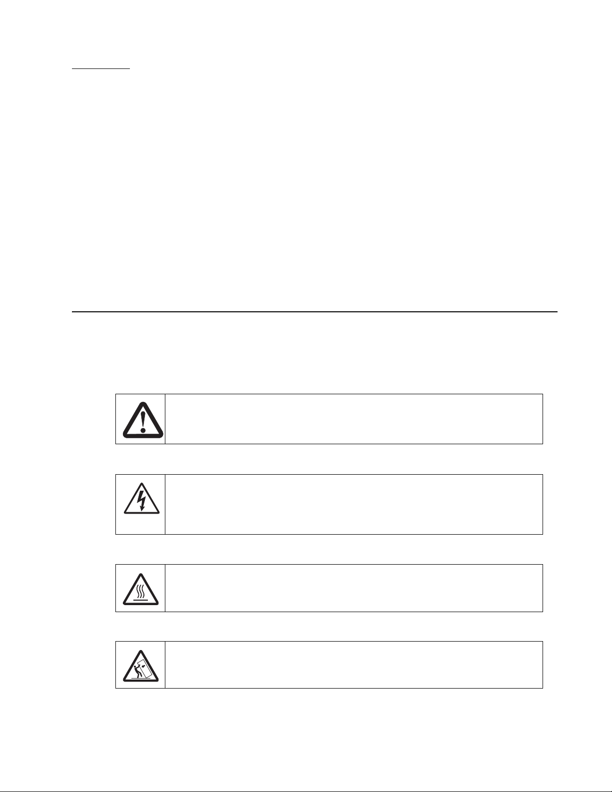
There are several types of caution statements:
CAUTION
A caution identifies something that might cause a servicer harm.
CAUTION
This type of caution indicates there is a danger from hazardous voltage in the area of the
product where you are working. Unplug the product before you begin, or use caution if the
product must receive power in order to perform the task.
CAUTION
This type of caution indicates a hot surface.
CAUTION
This type of caution indicates a tipping hazard.
Preface -xix

7100-XXX
-xx Service Manual

7100-XXX
1. General information
The Lexmark™ X500n and X502n are color laser MFPs that combine print, scan, copy, and fax functions.
The X500n and X502n are the ideal MFPs f o r prese ntation s , b u siness g ra phics , line art, and text. The y use
laser diode electrophotographic t echnology to deliver remarkable quality print images and text. The scan
and copy functions work with A4 , letter, and legal (ADF only) size paper. Photographic quality images are
possible with scan function. The FAX function delivers a wide range of functionality to the office user. The
MFPs can be used as shared network or desktop devices.
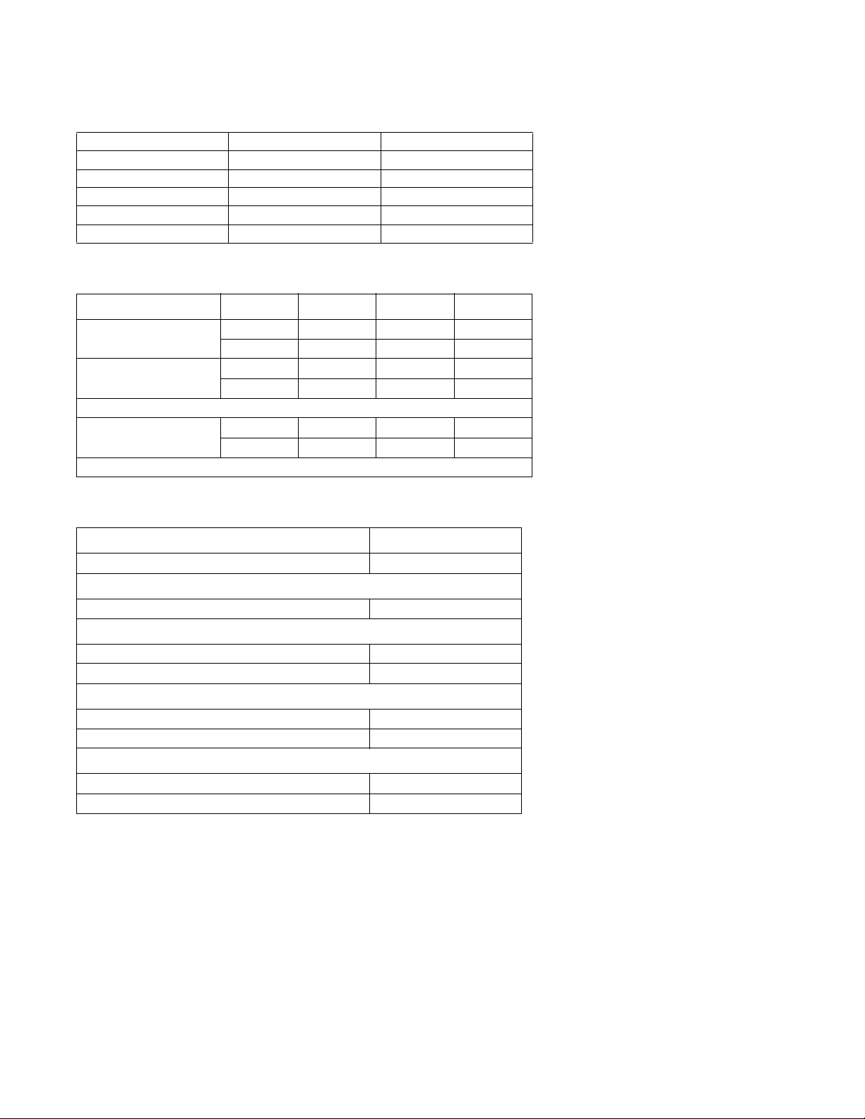
Models
The Lexmark X5xx MFPs are available in the following models:
Model Configuration Machine type
X500n Print, copy, scan, networ k 7100-010
X502n Print, copy, scan, fax, network 7100-110
General information 1-1

7100-XXX
MFP Specifications
General device technical specifications
Interfaces
X500n X502n
USB 2.0 X X
Ethernet 10/100 Base T X X
Note: The USB 2.0 and network interfaces can be used simultaneously.
The USB interface supports:
• Windows 98 SE
• Windows Me
• Windows NT
• Windows 2000 Professional
• Windows XP Operating Systems
• Windows Server 2003 Operating Systems
• Windows Vista 32/64 bit
• Macintosh OS X version10.1–10.4 (Power PC and Intel)
Note: For USB attachmen t, a USB ca ble (P/N 12A2405) is recommen de d a nd m u st b e o rde red sep arately.
The standard Ethernet connection and optional N2100 Series print servers support the following protocols:
• TCP/IP—The TCP/IP standard set of application services are supported including DHCP, BOOTP,
WINS, SNMP (MIB-2, host resources MI B , printer MIB , enterprise MIB, SNMP t ra ps), HTTP, LPR/LPD,
FTP, IPP1,SLP, DDNS
• AppleTalk
This MFP with standard Ethernet supports an Embedded Web Server. The current status of the operator
panel is viewable using the resident Web pages.
Processor
ARM-11core running at 366mhz.
Supported operating systems
This MFP is compatible with applications running under the following operating systems for either local or
network connections:
Macintosh
• Macintosh OS X version 10.2–10.4 and above. (Power PC and Intel)
The software applications that operate with most Apple LaserWriter printers will generally operate with this
printer.
Download the latest Lexmark printer PPD files or printer drivers from www.lexmark.com.
1-2 Service Manual

7100-XXX
Microsoft Windows
• Microsoft Windows Me
• Microsoft Windows 2000 Professional
• Microsoft Windows 2000 Server
• Microsoft Windows 2000 Advanced Server
• Microsoft Windows XP Home
• Microsoft Windows XP Professional
• Microsoft Windows Server 2003
• Microsoft Windows Vista 32/64 bit
Download the latest printer drivers from http://www.lexmark.com.
The Windows software applications , which oper ate in the oper atin g systems liste d abo v e , ar e best suited to
run with the drivers supplied with this MFP. The drivers for Windows take advantage of the MFP’s functions
and increase the MFP’s performance wherever possible.
Memory configuration
Standard DRAM 128MB
Optional SDRAM N/A
Max DRAM 128MB
Physical specifications and weight (WIP)
The following table contains the dimensions and weights for each MFP model and option. This does not
include packaging but does include the print cartridge that ships with the MFP.
Width Depth Height Weight
inch inch inch lb
mm mm mm kg
MFP
Lexmark X500n/
1
X502n
Paper options
530-Sheet drawer 18.1 18.5 7.3 13.3
530-Sheet tray 11.2 14.4 4.5 4.2
Standard tray 10.8 13.0 2.2 2.2
Tray set to legal 10.8 15.9 2.2 2.4
1
Comes with standard input tray and starter cartridges.
2
Weight does not include packaging or pubs.
18.9 17.2 21 77.0
480 437 531 35.0
460 470 185 6.0
285 365 115 1.9
275 330 55 1.0
275 405 55 1.1
2
General information 1-3
7100-XXX
Operating clearances
MFP sides X5xxn X5xxn with 530-sheet tray
Left side 8 in (203 mm) 8 in (203 mm)
Right side 20 in (508 mm) 20 in (508 mm)
Front 28 in (711 mm) 28 in (700 mm)
Rear 10 in (254 mm) 10 in (254 mm)
Top 16 in (400 mm) 16 in (400 mm)
Packaging and shipping dimensions
Width Depth Height Weight
MFP* in in in lb
mm mm mm kg
X500n / X502n 23.4 22.6 29.9 77
595 575 760 42.0
Options
530-Sheet drawer 21.9 22.4 10.9 18.7
556 570 277 8.5
* Includes start-up kit (supplies)
Power a nd electrical specifications
Printing states X5xxn
Off 0 W
Average power while operating
Continuous printing 670 W
Power consumption, standby
Power saver on 35 W
Power saver off 200 W
Maximum current while operating
115 Volts 11 A
230 Volts 6 A
Average current while operating
115 Volts 6.0 A
230 Volts 3.0 A
1-4 Service Manual

Environment
Environment Specifications
Operating
Air temperature–product operating 10 to 32.5°C (50 to 90.5°F)
Air temperature–product power off 5 to 35°C (41 to 95°F)
Air relative humidity 15 to 80%
Altitude 0–2,500 m (0–8,200 ft.)
Ship / Storage
Temperature-printer and supplies 0 to 35°C (32 to 95°F)
Relative humidity 10 to 90% RH
Atmospheric pressure 613 to 1607 hPa (460 to 800 mm Hg)
Severe High 35 to 40°C (95 to 104°F), Severe Low -10 to 0°C (14 to 32°F). The period under severe shall not be deemed to be
*
continuous, but rather a total of such intermittent periods (48 hours at most for any one period).
*
7100-XXX
General information 1-5
7100-XXX
Print engine specifications
Print engine resolution
600 x 600 dpi, 1200 x 600 dpi
Color balance settings
This MFP offers color balance control. It is a color correction option that allo ws you to increase or decrease
the amount of toner going to the page for all four color planes. The scale ranges from -10 to +10.
Emulations
Raster Graphics (CMYK bi-tone JBIG Compressed)
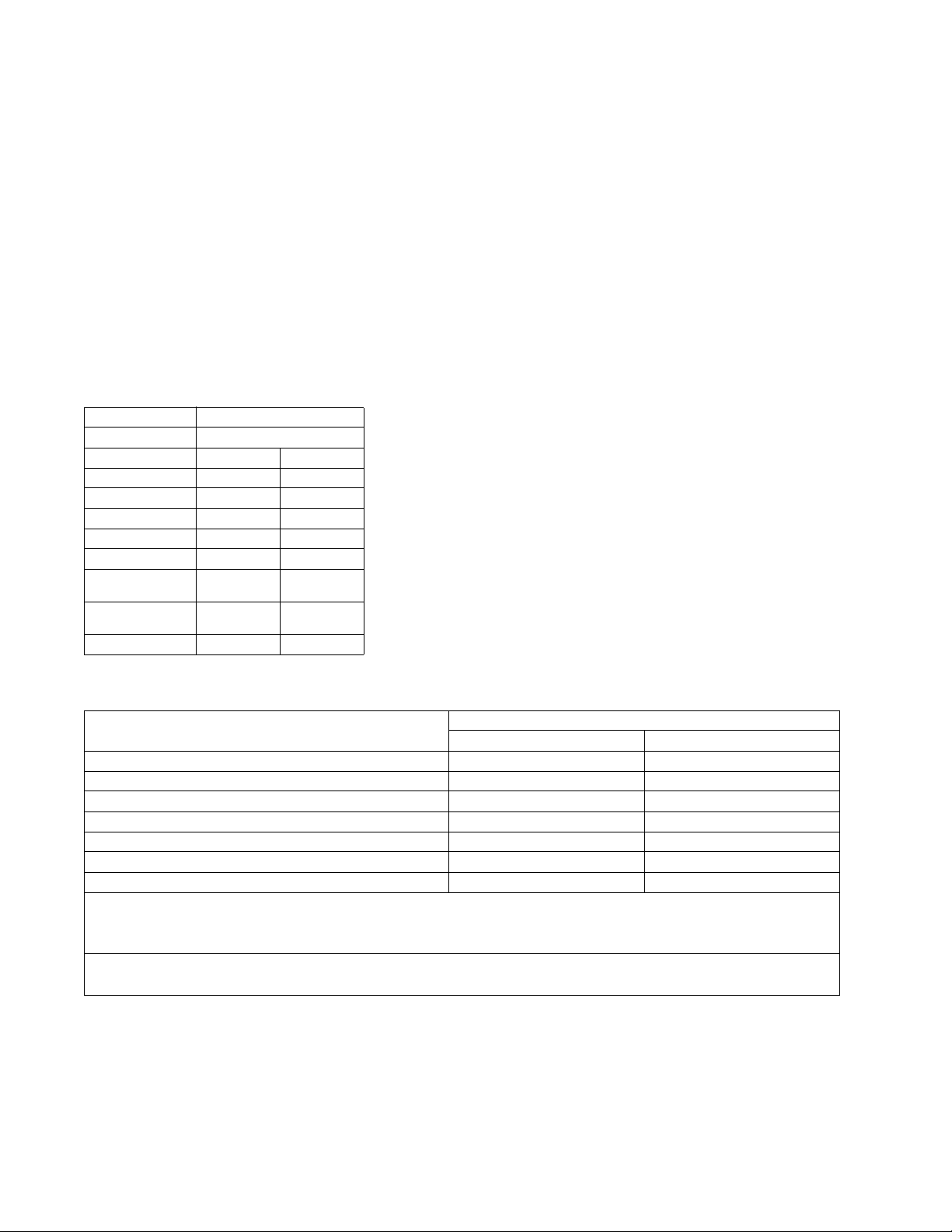
Print engine speed and performance
Pages/minute)
Media size Standard tray
Mono Color
Letter Up to 31 Up to 8
A4 Up to 31 Up to 8
Legal Up to 16 Up to 8
Transparencies Up to 3 Up to 2
Thick card stock Up to 3 Up to 2
Labels (letter &
A4)
Medium thick card
stock (letter & A4)
Envelopes Up to 5 Up to 3
Up to 5 Up to 3
Up to 4 Up to 3
Print engine time to first print
Media type/Media size First print time
Mono Color
Plain paper mode / A4, letter 13 seconds 19 seconds
Transparency mode / A4, letter 23 seconds 29 seconds
Label–middle thickness stock / A4, letter 17 seconds 23 seconds
Middle thick stock–glossy / A4, letter 16 seconds 22 seconds
Thick stock / A4, letter 23 seconds 29 seconds
Envelope (1) mode / Commercial #10, International DL 18 seconds 24 seconds
Envelope (2) mode / Commercial #10, International DL 23 seconds 29 seconds
Note: Note: Time to first page (TTFP) is the time from the moment when the host sends the print signal
until the moment the trailing edge of the first page leaves the exit feed rollers. TTFP is measured using a
simple text (single character) page.
Note: Note: Warm up time, 60 seconds maximum, is the time elapsed from when the power is turned on
to when the Ready status is reached.
1-6 Service Manual

7100-XXX
Print engine paper and media specifications
Print area
The printable area is up to 4.0 mm (0.158 in) from the top and bottom of the media, and up to 3.0 mm
(0.118 in) from the left and right edges. Any information placed outside this specified printable area will not
print. For envelopes, the printable area is up to 4.0 mm (0.158 in) of the left and right edges, and 3.0 mm
(0.118 in) of the top and bottom edges.
Print engine input and output configurations
The following table shows the standard number of input sources and output destinations, as well as the
estimated capacity of each. Capacity may vary and is subject to media specifications and MFP operating
environment. The capacities listed are based on plain paper at 75 g/m
Sources and capacities X500n / X502n
Input sources
Number of standard sources 1
Number of optional input drawers 1
Maximum number of input sources
Maximum input capacity 780
Standard input
Primary tray capacity 250
Total standard capacity 250
Optional input
Optional tray 1 capacity 250
Optional tray 2 capacity 530
Number of standard destinations 1
Output capacities
Standard output bin capacity (top)
Media up to 20 lb paper 250
1
Optional input drawer is a 530-sheet capacity drawer. Only one optional drawer may be installed at any time.
2
The MFP supports top output (facedown) as standard. No additional output options are available.
Note: All capacities are based on use of 20 lb paper.
1
Input capacities
Output destinations
2
2
.
2
General information 1-7

7100-XXX
Media input types and weights
Source Type Standard tray
530–Sheet tray MFP menu Item
Legal tray
Paper
type
1,2
Paper
(grain long)
Card stock Index 163 g/m
Index 164–210 g/m
Transparency
Labels
3
2
Envelopes 75–90
1
Punched, embossed, water-marked, perforated, punched, inkjet paper or plastic-coated media should not be used.
2
Only occasional use of paper labels in an office environment is supported.
3
Only PN 12A5940 and 12A5941 should be used.
Xerographic or bond
paper
Xerographic or bond
paper
100% Cotton 75–120
60–74
2
g/m
(16-19 lb)
75–120
2
(20-32 lb)
g/m
2
g/m
(24-32 lb)
(90 lb)
(91-110 lb)
PN 12A5940
PN 12A5941
2
g/m
(20–24lb)
2
60–74
2
g/m
(16-19 lb)
75–120
g/m2 (20-32 lb)
75–120
2
g/m
(24-32 lb)
Plain paper Light
Plain paper Normal
Plain paper Heavy
N/A Card stock Normal
2
N/A Card stock Heavy
N/A Transparency
N/A Label
N/A Envelope Normal
There is no automatic paper type sensing. These settings should be manually set in the operator panel.
Paper
weight
1-8 Service Manual
7100-XXX
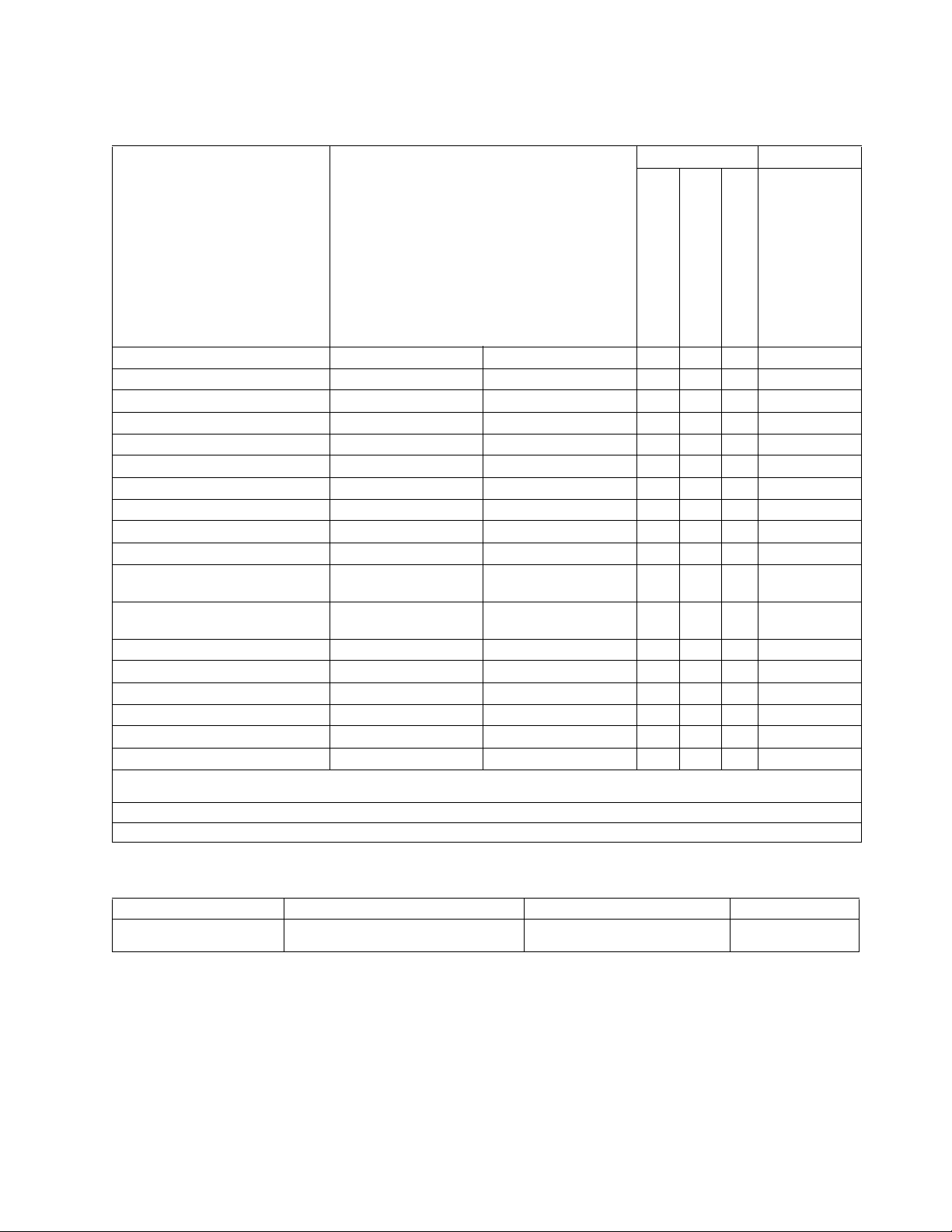
Media sizes
Media sizes Dimensions Input Output
2
Universal 250-sheet tray 1Standard setting
Universal 250 sheet tray
Set to legal
Optional 530-sheet tray
Standard 250-sheet bin
mm in
A4 210 x 297 8.27 x 11.7 X X X X
A5 148 x 210 5.83 x 8.2 7 X X
3
JIS B5
Letter 216 x 279.4 8.5 x 11 X X X X
Legal 216 x 356 8.5 x 14 X X
Executive 184.2 x 266.7 7.25 x 10.5 X X X X
Folio 216 x 330 8.5 x 13 X X
Statement 139.7 x 215.9 5.5 x 8.5 X X
Universal
1
Standard 250–sheet letter tray 104.8 x 210 to 215.9 x
Optional 250–sheet legal tray 104.8 x 210 to 215.9 x
Envelope sizes Dimensions Dimensions
9 Envelope
2
COM 10 Envelope 104.8 x 241.3 4.12 x 9.5 X X X
DL Envelope 110 x 220 4.33 x 8.66 X X X
C5 Envelope
B5 Envelope
1
Select Universal when using a non-standard size sheet of print material. The MFP formats the page for the maximum size 8.5 X 14
in(215.9 X 355.6 mm). Set the actual size from your software application.
2
Supported through the driver.
3
B5 may be supported in optional tray 1, but size sensing must be turned off.
2
2
182 x 257 7.17 x 10.1 X X X
XX X
4.125 x 8.27 to 8.5 x
297
11.7
4.125 x 8.27 to 8.5 x 14
355.6
98.4 x 225.4 3.875 x 8.9 X X X
162 x 229 6.38 x 9.01 X X X
176 x 250 6.93 x 9.84 X X X
Output capacity by media and source
Source Media Capacity Orientation
Standard output bin (top)¹ Supports all sizes listed in the “Media
sizes” table
250 sheets (20 lb paper)
50 Transparencies
Collated
Facedown
General information 1-9

7100-XXX
Scan specifications
Resolution 1200 X 2400 dpi
Scan size 216mm X 297 mm (flatbed), Window size 220mm X 300mm
Scan depth 48 bits
Lamp warm up time Less than 3 seconds
MTF More than 30%
Depth of focus -2 mm to +2 mm
Magnification Less than 0.5%
Scanning TWAIN
Connectivity USB 2.0, and Ethernet (10/100 Base TX-TCP/IP only)
Push scan Scan to E-mail, scan to FTP, scan to host PC
Web status monitor Yes
Scanner driver (TWAIN) features
Scan mode True color, grayscale, black & white
Contrast adjustment Yes
Brightness adjustment Yes
Color / Mono switch Yes
Scan to E-mail feature
Network requirements TCP/IP and an SMTP gateway
Authorization function SMTP authentication, POP3 before SMTP
Register E-mail address By Web page
Scan destination Set up in scan profile
E-mail address maintenance By Web page
Job Search By profile name
Subject input 20 characters maximum. Entered by the Web page interface
Maximum E-mail data size
Supported file formats TIFF, JPEG, PDF
1-10 Service Manual

Copy specifications
7100-XXX
Resolution 600 dpi X 600 dpi (flatbed), 600 X 300 dpi(ADF), Print from copy – 600 X 600 dpi
Original paper sizes A4, Letter, Legal (ADF only), B5 (JIS), Executive
Copies per minute Mono: up to 21, Color: up to 7
Time to first copy Less than 30 seconds
Multiple copies 99 copies maximum
Output paper sizes A4, Letter, Legal (optional cassette only)
Image density adjustment 5 levels, manual only
Image quality modes Text, Photo, and Mixed
Zoom 25% to 400% in increments of 1%
Present reduction ratio US: 25%, 65%, 78%, 93%
Present enlargement ratio US: 129%, 155%, 200%, 400%
Advanced copier features
Combine multiple copies into one copy. 2 into 1, 4 into 1. Can be toggled between landscape and portrait.
Electronic sort Yes
Scan once print many Yes
Limitless paper feed Yes
Memory copy Standard
Copy counter indicator Standard
Jam recover auto restart For print jams only.
Buzzer to finish job Yes
ADF
ADF width 5.5 to 8.5 inches (139.7 to 215.9 mm)
ADF length 5.5 to 14 inches (139.7 to 355.6 mm)
ADF capacity 35 sheets
- assumes 50% coverage
1
2 - Does not include scanner and printer warm-up time.
9600 dpi X 9600dpi w/ software interpolation
1
2
EU: 25%, 71%, 86%, 93%
EU: 122%, 141%, 200%, 400%
Fax specifications
Phone network connectivity
Phone networks types supported Both PSTN and PABX are supported.
Compatibility T30(ITU-T Super G3) is supported.
Modem speed Automatic fallback: 33600 bps
Compression MH, MR, MMR, and JBIG
Color fax is not supported.
V34, V17, V29, and V27ter are supported for image
transmission. V8, and V21 are supported for control channels.
General information 1-11

7100-XXX
Document Sizes supported
ADF width 5.5 to 8.5 inches (139.7 to 215.9 mm)
ADF length 5.5 to 14 inches (139.7 to 355.6 mm)
ADF capacity 35 sheets
Flatbed width 8.5 inches (216 mm)
Flatbed length 11.7 inches (297 mm)
Scanning width 215.9 mm maximum
Printing width Legal — 215.9 mm X 355.6 mm
Letter — 215.9 mm X 279.4 mm
A4 - 210.0 X 297.0 mm
Fax scan resolutions
Horizontal
Fixation 200 dpi 8 dot/mm
Vertical
Standard 100 dpi 3.85 dot/mm
Fine 200 dpi 7.7 dot/mm
Photo 200 dpi 7.7 dot/mm
Miscellaneous FAX specifications
Halftone/error diffusion Error diffusion
Speed dial 50 entries (name 20 characters, number 40 digits)
Quick dial 20 entries (name 20 characters, number 40 digits)
On hook dial Yes
Direct Fax number entry Yes
Re dial Yes
Transmission
Immediate transmission Yes
Memory transmission Yes
Page retransmission Yes
Error correction mode Yes
Broadcasting Yes (100 entries)
Reception
FAX only mode Yes
Manual mode Yes
Auto reduction Yes (Threshold 74%)
Error correction mode Yes
Reports
Activity report Yes
Transmission verification report Yes
Power failure report Yes
Phone book list Yes
Quick dial list Yes
Speed dial list Yes
Memory manage list Yes
User parameter list Yes
Clear memory transmission file
Memory job clear Standard
All clear Standard
1-12 Service Manual

7100-XXX
Media guidelines
Paper designed f or use with x erog raphic copiers should provide satisf actory print quality and feed reliability.
Other media types may be suitable. We recommend that users test any particular brand for suitability to
their applications. Refer to the MFP User's Guide for additional med ia specifications.
Paper
• Rough, highly textured, limp, or pre-curled papers will result in lower print quality and more frequent
paper feed failures.
• Colored papers must be able to withstand 338°F (170°C) fusing temperature.
• Preprinted forms and letterheads should be selected using guidelines in the MFP User's Reference.
The chemical process used in preprinting may render some papers unsuitable for use with the MFP.
• Unsuitable papers include punched, embossed, water-marked, perforated media, any kind of inkjet
paper or plastic-coated paper.
• Recycled paper less than 75 g/m
The laser printing process heats paper to high temperatures of 170°C (338°F). Use only paper able to
withstand these temperatures without discoloring, bleeding, or releasing hazardous emissions. Check with
the manufacturer or vendor to determine whether the paper you have chosen is acceptable for laser
printers.
2
(20 lb) may cause unacceptable results.
Envelopes
Should be fed with short edge first, flap down and to the right.
• If envelope wrinkling occurs, refer to the User's Reference for correct loading and stacking of
envelopes.
• All envelopes should be new, unused, and without damage.
• Envelopes with e xcessiv e curl or twist e xceeding 6.0 mm, those stuc k together, those with bent corners
or nicked edges, or those that interlock should not be used.
• Minimum weight: 90 g/m
2
(24 lb).
• The following envelopes should not be used:
– Envelopes with windows, holes, perforations, cutouts, or deep embossing
– Envelopes with metal clasps, string ties, or metal folding bars
– Envelopes with exposed flap adhesive when the flap is in the closed position
– Self-seal envelopes
• Under high-humidity conditions (over 60%), the envelopes may seal during printing.
• For best results, print on new 90 g/m
Transparencies
2
(24 lb) sulfite or 25% cotton-bond envelope.
• Use letter (12A5940) or A4-size (12A5941) sheets only.
• Transparencies are only supported in tray 1 (standard or legal trays).
General information 1-13

7100-XXX
Labels
• Labels should be selected using guidelines found in the User's Guide, Complete Printer Guide, or the
Card stock & Label Guide (located at www.lexmark.com), and tested for acceptability.
• Vinyl labels are not supported.
• Labels are only supported in tray 1 (standard or legal trays).
Glossy Paper
• Use letter (12A5950) or A4-size (12A5951) sheets only.
• Glossy paper is only supported from tray 1 (standard or legal trays).
Sensing by source
Input Paper size Paper out Tray present
Integrated 250-sheet
Optional 530-sheet
XXX
XXX
1-14 Service Manual

Maintenance approach
The diagnostic information in this manual leads you to the correct field replaceable unit (FRU) or part.
Use the error code charts, symptom index, and service checks to determine the symptom and repair
the failure. The removals in the repair information chapter may help you identify parts.
• Printer messages
• Symptom tables
• Service checks
• Repair information
After you complete the repair, perform tests as needed to verify the repair. See “Diagnostic aids” on
page 3-1.
Standard inspection and cleaning procedure
• Switch off printer power, and disconnect the AC power cord from the electrical outlet.
• Remove and inspect the photodevelopers and toner cartridges, shielding them from strong light.
• Inspect the interior of the printer , removing foreign matter such as pa per clips, staples, pieces of paper
or transparencies, paper dust, hair, oil, grease, or toner.
• Clean the printer interior using a lint-free cloth. Do not use solvents or chemical cleaners to clean the
printer interior.
• Use only the specified oil or lubricant on printer parts (some service parts are lubricated at the factory).
• Inspect and, if necessary, clean all rubber/plastic rolls with a lint-free cloth. Dry the rolls with a lint-free
cloth.
• While cleaning, inspect the interior of the printer for damaged wires, loose connections, toner leakage,
loose springs, and damaged or worn parts.
• Be sure the printer is on a single, flat, strong table or desk top.
• Inspect all supplies (OCR, cartridges, photodev elopers/toner cartridges, belts, fuser maintenance kits
and paper sources (cassettes, trays, feeders, duplex drawers, finisher, mailbox trays) for obvious
damage and proper installation (paper guides not too tight). Inspect for correct media usage (paper,
transparencies, labels).
• Print demo page.
• If additional paper sources are installed, print a demo page from each of these (if possible).
• Failure to print from an a dditional tray or feeder may imply one or more pi ns are bent in the mating
connector.
7100-XXX
General information 1-15

7100-XXX
Serial number
Look for serial number information on the right cover and the inside of the front cover of your MFP.
Tools required for service
The removal and adjustment procedures described in this manual require the following tools and
equipment:
• Analog volt ohmmeter (A digital volt ohmmeter may also be used.)
• Flat-blade screwdrivers
• Needle-nose pliers
• #1 Phillips screwdriver
• #2 Phillips screwdriver
• Slotted screwdriver #1
• Slotted clock screwdriver #1
• Tweezers, C-ring pliers
When you make voltage readings, always use frame ground unless another ground is specified.
1-16 Service Manual

Acronyms
ADF Automatic document feeder
ASIC Application specific integrated circuit
BOOTP Boot protocol
CCD Charge coupled device
DDNS Dynamic domain name service
DHCP Dynamic host configuration protocol
DPI Dots per inch
DRAM Dynamic random access memory
EP Electrophotographic process
ESD Electrostatic discharge
FRU Field replaceable unit
HTTP Hypertext transport protocol
HV High voltage
HVPS High voltage power supply
JBIG Joint Bi-Level Image Experts Group
LAN Local area network
LASER Light amplification by simulated emission of
radiation
LCD Liquid crystal display
LED Light emitting diode
LV Low voltage
LVPS Low voltage power supply
MFP Multiple function printer
NVRAM Nonvolatile random access memory
MH Message handling
MMR Modified modified read
MR Modem ready
OEM Original equipment manufacturer
PABX Private automatic branch exchange
POR Power-on reset
POST Power-on self test
PQET Print quality enhancement technology
PSTN Public switched telephone network
RIP Raster image processor
SMTP Simple mail transport protocol
SDRAM Synchronous dynamic random access memory
SNMP Simple network management protocol
TAD Telephone answering device
TCP/IP Transmission control protocol Internet protocol
VAC Volts alternating current
VDC Volts direct current
WINS Windows internet name service
7100-XXX
General information 1-17

7100-XXX
1-18 Service Manual

7100-XXX
2. Diagnostic information
Start
CAUTION: Remov e po wer from th e printer bef ore y ou connect or disconne ct any cab le , electronic board or
assembly, for personal safety and to prevent damage t o the printer. Always use the hand grips on the side
of the printer and be sure your fingers are not under the printer when you set the printer down.
Use the service error codes, user status messages, user error messages, symptom tables, service checks,
and diagnostic aids, to determine the corrective action necessary to repair a malfunctioning printer.
Service error codes are indicated by a two-character alphanumeric error code. If a service error code
displays, go to the “Service error codes” on page 2-3.
User status messages provide the user with information on the current status of the printer. “Ready”
displays on the first line of the display unless Power Saver is invoked, then Power Saver is displayed. If a
user status message displays, go to the “User attendance messages” on page 2-8.
User error messages are indicated by a two- or three-digit error code which provides the user with
information explaining a problem with a print cartridge, paper jam, option, port, and so on. If a user error
message displays, go to the“User attendance messages” on page 2-8.
The User Messages section sometimes allows a servicer to isolate printer problems. This section also giv es
actions to be taken when they do not set or clear.
If you hav e a failing symptom, go to the “Symptom tables” on pa ge 2-11. Locate your symptom, and take
the appropriate action.
If a service error code appears while you are working on the printer, go to the “Service error codes” on
page 2-3 and take the appropriate action.
Diagnostic information 2-1

7100-XXX
Understanding the operator panel
Using the MFP menus
Copy Settings
Paper Select
Sort
Density
Quality
Reduce/Enlarge
Scan Settings
Document Size
Multi Page in A Document
Limitless Scan
Color Compress Ratio
Resolution
Density
Limitation of size of mail
Machine Settings
Speaker Volume
Paper Settings
Job Timeout
Auto Continue
Toner Saver Mode
Supplies info
Scanner Carriage
Fax Settings
TX Settings
RX Settings
Tray Settings
Delete Document
Comm Settings
Report Settings
Network Settings
Ethernet
IP Configuration
Fax Directory
Quick Dial Entry
Speed Dial Entry
Reports Print
Configuration Page
Activity Report
Memory List
Quick Dial List
Speed Dial List
Scan Directory
Scan Transmission Log
Demo Page
Maintenance Page
Admin Settings
Date /Time Setup
User Settings
TEL Line Type
PBX Selection
PBX Access Digit
Default Mode
Auto Clear
Power Saver
Display Language
Country Code
Setting Default
Admin Menu Lock
2-2 Service Manual

Service error codes
Error code Action
7100-XXX
001 Service Call
System Board - CPU
002 Service Call
System Board - Flash
003 Service Call
System Board - DRAM
004 Service Call
System Board - RTC
009 Service Call
System Board
005 Service Call
Op Panel
006 Service Call
Scanner Unit
007 Service Call
Printer Communication Error
008 Service Call
Fax Card
Replace the RIP board. See “System board removal” on page 4-36. Or replace
the engine controller board. See“Engine controller board removal” on
page 4-34.
See “Operator panel service check” on page 2-40.
Scanner unit initialization failed. Home position not found. Possible scanner
calibration failure. See “Flatbed service check” on page 2-41.
Print engine fails to initialize. See “Engine controller board removal” on
page 4-34.
Fax board f ails to initialize or f ails to respond when a fax is sent. See “Modem / fax
card service check” on page 2-43.
C3 Service Call
Engine CTL Board
C4 Service Call
Engine CTL Board
C7 Service Call
Main Motor
D4 Service Call
LV Power Supply
E0 Service Call
Developer Motor 1 - MK
E1 Service Call
Developer Motor 2 - CY
incorrect data is detected in the NVRAM during data confirmation process at
power-on.
1. POR the machine.
2. If problem persists, replace the controller board.
Defective engine controller board is causing faulty data transmission between ASIC
and CPU.
POR the printer. If error still exists, replace the engine controller board. See
“Engine controller board removal” on page 4-34.
Synchronization signal from main motor is not detected.
See “Main motor service check” on page 2-14.
See “Low voltage power supply (LVPS) service check” on page 2-23.
An over-current signal is detected due to an abnormal load on developer motor 1.
1. Replace black and magenta toner cartridge.
2. If error persists, see “Developer drive assembly service check” on
page 2-16.
An over-current signal is detected due to an abnormal load on developer motor 2.
1. Replace yellow and cyan toner cartridge.
2. If error persists, see “Developer drive assembly service check” on
page 2-16.
Diagnostic information 2-3

7100-XXX
Error code Action
E2 Service Call
Main Motor
E3 Service Call
Transfer Belt Sensor
E5 Service Call
Transfer Roller Clutch
E6 Service Call
Transfer Cleaner Solenoid
E7 Service Call
P feed Clutch Tray 1
E8 Service Call
Registration Clutch
E9 Service Call
OPC Marker Sensor
EL Service Call
Erase Lamp
A NOT READY signal (rotation error signal) is detected because of abnormal main
motor rotation.
See “Main motor service check” on page 2-14.
Unstable transfer belt rotation—color matching cannot be secured.
See “Transfer belt unit service check” on page 2-17.
Improper transfer roller clutch cable connection or a shorted or cut cable.
See “T ransfer roller clutch service check” on page 2-18.
Improper cleaning roller clutch cable connection or a shorted or cut cable.
See “Transfer belt cleaning roller clutch service check” on page 2-18.
Improper paper-feed clutch cable connection or a shorted or cut cable.
See “Paper feed clutch service check” on page 2-19.
Improper registration clutch cable connection or a shorted or cut cable.
See “Registration clutch service check” on page 2-19.
Marker sensor is not properly detecting mark on OPC belt.
See “OPC belt marker sensor service check” on page 2-20.
Improper erase lamp cable connection or a shorted or cut cable.
Erase lamp LED terminal may be cut.
See “Erase lamp service check” on page 2-21.
F0 Service Call
Power Supply Fan
F4 Service Call
Fuser Fan
F5 Service Call
HV Power Supply Unit
F6 Service Call
LV Power Supply Unit
H0 Service Call
Fuser Unit
H1 Service Call
Fuser Unit
H2 Service Call
Fuser Unit
H3 Service Call
Fuser Unit
Improper fan motor rotation, improper fan motor cable connection or a shorted or
cut cable.
See “Power supply fan service check” on page 2-22.
Improper fan motor rotation, improper fan motor cable connection or a shorted or
cut cable.
See “Fuser fan service check” on page 2-22.
Output (BRV) of HVPS is shorted, and or HVPS cable connector is improperly
connected.
See “High voltage power supply (HVPS) service check” on page 2-23.
Data communication error between LVPS and the engine controller board.
See “Low voltage power supply (LVPS) service check” on page 2-23.
Temperature signal from thermistor is not detected.
See “Fuser thermistor service check” on page 2-24.
Circuitry that controls the fuser temperature has failed.
See “Fuser assembly service check” on page 2-24.
Fusing temperature is not reached within the warming-up time period.
See “Fuser assembly service check” on page 2-24
Fusing temperature drops below fusing threshold during the printing process and
does not reach fusing temperature again within alloted time .
See “Fuser assembly service check” on page 2-24.
.
2-4 Service Manual

Error code Action
7100-XXX
H4 Service Call
Fuser Unit
HA Service Call
Fuser Unit
L1 Service Call
Laser Unit Assembly
L2 Service Call
Laser Unit Assembly
LL Service Call
Laser Unit Assembly
N3 Service Call
HVPS Connection
N4 Service Call
Toner Empty Sensor
N5 Service Call
Toner Empty Rcv
Fusing temperature rises above limit during printing process and does not return
within the alloted time period.
See “Fuser assembly service check” on page 2-24.
AC relay turned off due to an abnormal temperature.
See “Fuser assembly service check” on page 2-24.
Laser scanning beam is not detected by beam sensor.
See “Laser unit assembly service check” on page 2-25.
Scanner motor (SM) is rotating abnormally.
See “Laser unit assembly service check” on page 2-25.
Laser power is lower than the output limit.
See “Laser unit assembly service check” on page 2-25.
Improper connection between engine controller board and HVPS.
See “HVPS connection service check” on page 2-25.
Improper connection between engine controller board and toner sensor sender
board.
See “T oner empty sensor (sender-TPD) service chec k” on page 2-26.
Improper connection between engine controller board and toner sensor receiver
board.
See “T oner empty sensor (receiver-TTR) service check” on page 2-27.
N6 Service Call
LFU Connection
P6 Service Call
Pfeed Clutch Tray 2
Improper connection between engine controller board and lower paper feed unit.
See “Lower feed unit (secondary paper assembly) service check” on
page 2-28.
Data communication error between engine controller board and LFU paper-feed
clutch.
See “Lower feed unit (secondary paper assembly) service check” on
page 2-28.
Diagnostic information 2-5

7100-XXX
User status messages
Message Description Action
Tray (1, 2) Missing The upper or lower tray is
missing.
Toner Low (C,M,Y,K) The toner is low in the
cartridge indicated.
Sleep The MFP is idle. These are the normal operating modes.
Please Wait The MFP is warming up.
READY The MFP is ready to
perform a task.
PC Printing The MFP is printing.
Calibrating The MFP is calibrating.
Connected to Server The MFP is connected to
a server for a push scan
job.
Sending File... A scan job is being
transmitted.
Send E-mail Notification An e-mail is being sent to
a user notifying them of a
push scan job being
completed.
install the upper or lower tray. If the problem
persists, see “Paper tray missing service
check” on page 2-30.
See “Toner low/empty service check” on
page 2-31.
Connection Fail Unable to connect to the
No Response The device
Busy The remote fax device is
Dial Failed The dial attempt to
Scanning Page The scanner is scanning
Job # Fax Job # is being
Dialing A fax number is being
Awaiting Re dial The fax is between dialing
Transmitting The fax is transmitting
Receiving The X502 is receiving fax
remote fax.
currently busy.
another device failed.
in the flatbed or ADF.
processed.
dialed.
attempts.
data to another fax device.
data from a remote fax
device.
2-6 Service Manual

Message Description Action
7100-XXX
TAD Answering A telephone call is being
received.
Answering The fax is answering an in
coming call.
incoming Call There is an incoming call
on the phone line
Warming Up The MFP is warming up.
These are the normal operating modes.
Diagnostic information 2-7

7100-XXX
User attendance messages
Message Description Action
Paper Empty
(Load Tray - Paper Size, Load
Tray 1 Paper Size, Load Tray 2
Paper Size, Load Tray Paper)
Paper Change
Load Paper <Type, Size>
Paper Error
Load Tray 1 <Paper Type>
Tray (1, 2) Missing The upper or lower tray is
Toner Low (C,M,Y,K) The toner is low in the
C/M/Y/K Toner Empty
Replace Toner C/M/Y/K
Waste Pack Full The waste toner bottle is
The upper or lower paper
tray is empt y or the me dia
in the trays is inconsistent.
Media size and type
mismatch.
Media type mismatch. Load the paper tray with the correct media type.
missing.
cartridge indicated.
The specific toner
cartridge needs to be
replaced. in most cases,
only one of the letters
CYMK will appear.
full or not installed.
Fill up the paper tray(s) or replace the media with
the correct type. If the problem persists, see
“Tray empty service check” on page 2-29.
• Check the media size.
• Check the media size setting in the cassette.
• Check to make sure the media setting on the
printer and drive match the media in the
cassette.
install the upper or lower tray. If the problem
persists, see “Paper tray missing service
check” on page 2-30.
See “Toner low/empty service check” on
page 2-31.
install the appropriate toner cartridge. If prob l em
persists, see “Toner low/empty service check”
on page 2-31.
install the waste toner bottle or re pl a c e the full
waste toner bottle. If problem persists, see
“Waste toner bottle service check” on
page 2-31.
OPC Exhausted
Replace OPC Belt
OPC Belt Life
Replace OPC Belt
Fuser Life
Replace Fuser
TR Belt Life
Replace Transfer Belt
Missing
install Fuser Unit
2-8 Service Manual
Replace with a new OPC
unit.
Replace with a new OPC
unit.
Replace with a new fuser
unit.
Replace with a new
transfer belt unit.
The fuser is not installed. If fuser is installed, remove it and reinstall. If
See “Photodeveloper cartridge removal” on
page 4-8.
See “Photodeveloper cartridge removal” on
page 4-8.
See “Fuser assembly removal” on page 4-6.
See “Transfer belt unit removal” on page 4-5.
problem persists, check the cable that connects
engine controller board connector FUCN and
fuser. If the cable is bad, replace the cable.
Otherwise, replace the engine controller board.
See “Engine controller board removal” on
page 4-34.

Message Description Action
7100-XXX
Toner Error
install Supported Cartridge
Missing
install Toner (C,M,Y,K)
Missing
install OPC Belt
Missing
install Transfer Roller
Paper Jam A 1-2 Paper is jamming at
Paper Jam B Paper is jamming inside
Paper Jam C Paper is jamming at paper
Cover Open
Close (Front, Rear, OPC)
An invalid toner cartridge
is installed.
A toner cartridge is not
keyed properly.
The OPC belt cartridge is
not installed.
The transfer rol ler is not
installed.
feeding area.
the MFP.
exit area.
The back, front, or OPC
cover is open.
install a supported cartridge. If the problem
persists, see “Missing toner cartridge service
check” on page 2-32.
install proper brand of toner cartridge. If problem
persists, see “Missing toner cartridge service
check” on page 2-32.
Correctly install the photodeveloper cartridge to
clear message and continue printing. If error
persists, see “Missing photodeveloper
cartridge service check” on page 2-33.
Ensure transfer roller is properly installed. If
problem persists, see “Transfer roller missing
service check” on page 2-34.
See “P aper Jam A1, rear (tray 1)” on page 3-24
or “Paper Jam A2, rear (tray 2)” on page 3-26
for instructions to clear the jam.
See “Paper Jam B rear” on page 3-27 fo r
instructions to clear the jam.
See “Paper Jam C rear” on page 3-29 fo r
instructions to clear the jam.
Close specified cover if open. If not open, open
the cover and close. If the problem persists, see
“Cover open service check” on page 2-35.
TR Belt Life
Replace Transfer Belt
TR Kit Life
Replace PQ Kit
PF1 Kit Life
Replace PF Kit 1
PF2 Kit Life
Replace PF Kit 2
ADF Jam
Open ADF cover and Clear Jam
ADF Cover Open
Close ADF cover
Scan Calibration Error Scanner is out of
Scan Lock Error
Unlock Scanner
The transfer belt is at its
end of life.
The transfer roll and
transfer belt cleaning roll
have reached the end of
life.
The paperfeed roll and
separator pad in tray 1 are
at the end of life.
The paperfeed roll and
separator pad in tray 2 are
at the end of life.
A sheet of paper is
jammed in the ADF.
The ADF cover is open. Close the ADF cover. If the cover is already
calibration.
The scanner lock is in the
locked position.
Replace the transfer belt. See “Transfer belt
unit removal” on page 4-5.
Replace the transfer roll. See “Transfer roller
removal” on pa ge 4-6. Also, replace the transfer
belt cleaning roller. See “Transfer belt cleaning
roller removal” on page 4-4.
Replace the paperfeed roll and the separator pad
for the respective paper tray (1 or 2). See “Paper
feed roller removal” on page 4-32.
Clear the ADF jam. If the message persists, see
“ADF streak service check” on page 2-41.
closed, see “ADF streak service check” on
page 2-41.
Perf orm scanner calibration.
Unlock the scanner. If the scanner lock is in the
unlocked position, see “Flatbed service check”
on page 2-41.
Diagnostic information 2-9

7100-XXX
Message Description Action
Scan USB Disconnect The USB connection is
disconnected.
Scan Network Disconnect The network connection is
disconnected.
Duplicate IP Address Found Another device using an
identical IP address has
been detected on the
network.
E-mail Size Limit Exceeded E-mail memory buffer full. Retry the job. Break it up if needed.
Out of Memory Memory depleted. Retry the print job. Break it up if needed.
Scan Memory Full Memory for the scan job is
full.
Communication Error Communication with host
machine failed.
Server Connection Failed Communications with the
server failed.
(TX / RX) Comm Error There is a data
transmission or reception
error.
CPU fan locked The CPU fan is no longer
running on the RIP card.
See “USB service check” on page 2-40.
See “Network service check” on page 2-40.
Contact the network administrator.
Break the scan job into smaller segments.
Retry the job. Check all connections with the host
device.
Retry the job. Check all connections with the host
device.
Resend the fax.
See “CPU fan service check” on page 2-16.
Note: The expected yield of the separator pad and paperfeed roll are 120,000 pages.
2-10 Service Manual

Symptom tables
MFP symptom table
Symptom Action
Paper feed problems See “Paper feed service checks” on page 2-44.
Close door displayed when all doors are closed. See “User attendance messages” on page 2-8, and
follow the action suggested.
7100-XXX
Paper jam messages do not reset after removing
paper.
Toner cartridge does not turn or does not put toner on
the photodeveloper cartridge.
Developer motor makes noise or continuously runs. See “Developer drive assembly service check” on
Main motor makes noise or continuously runs. See “Main motor service check” on page 2-14.
T r ansfer belt unit makes noise when rotated or does not
rotate at all.
The transfer roll is not transferring images or does not
turn.
No power See “Printer no power service check” on page 2-38.
Waste toner feed problems See “Waste toner feed service check” on page 2-39.
Fans not working or making noise. See “Service error codes” on page 2-3. Find the failing
Print/image problems See “Print quality symptom table” on page 2-13.
Photodeveloper cartridge does not rotate or makes
noise.
Black copies from scanner. See “Black page copy service check” on page 2-41.
See “User attendance messages” on page 2-8, and
follow the action suggested.
See “Toner feed service check” on page 2-39.
page 2-16.
See “Transfer belt unit service check” on page 2-17.
See “White band service check” on page 2-63.
fan, and follow the action suggested.
See “OPC belt (photodeveloper) cartridge drive service
check” on page 2-36.
Fail to scan from the flatbed. See “Flatbed service check” on page 2-41.
Paper jams in the ADF. See “ADF paper feed service check” on page 2-42.
Paper skews when fed into the AD F. See “ADF paper feed service check” on page 2-42.
Paper fails to f eed into the ADF. See “ADF paper feed service check” on page 2-42.
Op panel failure See “Operator panel service check” on page 2-40.
Fax fails to transmit. See “Modem / fax card service check” on page 2-43.
Fax appears stretched or compressed. Issue with sending fax machine.
Streaks down the middle of a copy, fax or scan when
using the ADF
Scanner locked Check the scanner lock switch. If it is unlocked see
Scanner fails to communicate with the host PC. If the MFP is USB-attached, see “USB service check” on
See “ADF streak service check” on page 2-41.
“Flatbed service check” on page 2-41.
page 2-40. If the MFP is network-attached, see “Network
service check” on page 2-40.
Diagnostic information 2-11

7100-XXX
Symptom Action
No dial tone when sending a fax. See “Modem / fax card service check” on page 2-43.
Lines on outbound fax documents Check the flatbed glass for scratches or marks.
Words and images on inbound fax documents are
stretched out.
The sending machine had a temporary jam.
2-12 Service Manual

Print quality symptom table
Symptom Action
Background See “Background service check” on page 2-45.
Missing image at edge See “Missing image at edge service check” on page 2-53.
Jitter See “Jitter service check” on page 2-52.
Ribbing See “Ribbing service check” on page 2-57.
Wrinkle and image migration See “Wrinkle / image migration service check” on page 2-67.
White line See “White line II service check” on page 2-64.
White line See “White line II service check” on page 2-64.
V e rtical white band See “Vertical white band service check” on page 2-62.
Black line See “Black line service check” on page 2-48.
V ertical line See “Vertical line service check” on page 2-60.
V e rtical staggering image See “Vertical staggering image service check” on page 2-61.
7100-XXX
Banding See “Banding service check” on page 2-47.
White band See “White band service check” on page 2-63.
Toner drop See “Toner drop service check” on page 2-59.
White spots and black spots See “White spot / black spot service check” on page 2-65.
Mixed color image See “Mixed color image service check” on page 2-54.
Color misregistration See “Color misregistration service check” on page 2-49.
Mottle See “Mottle service check” on page 2-55.
Residual image See “Residual image service check” on page 2-56.
Insufficient gloss See “insufficient gloss service check” on page 2-51.
Back stain See “Back stain service check” on page 2 -46 .
White print See “White print service check” on page 2-66.
Insufficient fusing See “insufficient fus ing se rvice check” on page 2-50.
Diagnostic information 2-13

7100-XXX
Printer service checks
Main motor service check
Step Questions / actions Yes No
1 Turn printer off and remove right cover. See
“Right cover removal” on page 4-13.
Open top cover and override top cover
interlock switch. Restart printer, and
observe main motor and photodeveloper
cartridge OPC belt. Does main motor
attempt to turn but OPC belt will not rotate?
2 Observe main motor and fuser . Does main
motor attempt to turn but fuser will not?
3 Are there any unusual noises around main
motor before error posts?
4 Does noise go away? Problem solved. Go to step 5.
5 Is cable properly connected to main motor? Go to step 6. Properly connect cable.
6 If waste toner bo ttle is removed, reinsert it.
Ensure rear cover assembly cover is shut.
Override top and front cover interlock
switches. For location, see “Fan/moto r and
interlock switch locations” on page 5-6.
Reconnect operator panel. Turn printer on.
Allow printer to run until error posts.
Disconnect connector from main motor, and
check the following on disconnected cable
connector:
Replace photodeveloper
cartridge.
Note: photodeveloper
cartridge is a customerordered supply.
Replace fuser assembly.
See “Fuser assembly
removal” on page 4-6.
Note: Fuser is a customer-
ordered supply.
Replace main motor. See
“Main motor assembly
removal” on page 4-26.
Go to step 4.
Replace main motor. See
“Main motor assembly
removal” on page 4-26.
Go to step 9.
Go to step 2.
Go to step 3.
Go to step 5.
Retest printer. If error
clears, problem solved,
otherwise go to step 6.
Go to step 7.
Pin 4 to pin 5—24VDC
Pin 6 to pin 5—24VDC
Pin 10 to pin 5—5VDC
Are voltages present?
7 Remove engine controller board shield. See
“Engine controller board removal” on
page 4-34 for steps to remove engine
controller board shield. Disconnect MCN5
from engine controller board. Check for
continuity and shorted pins on cable that
connects MCN5 to main motor. Is cable
okay?
2-14 Service Manual
Go to step 8. Replace cable. Retest
printer. If error clears,
problem solved, otherwise
go to step 8.

Step Questions / actions Yes No
7100-XXX
8 Disconnect cable from engine controller
board POCN. Check the following on
disconnected cable connector:
Pin 21 to pin 22—24VDC
Pin 13 to pin 14—5VDC
Are voltages present?
9 Reassemble and retest printer. Does error
clear?
Replace engine controller
board. See “Engine
controller board removal”
on page 4-34. Go step 9.
Problem solved. Contact next level of
Replace cable that
connects ACN1 on LVPS to
POCN on engine controller
board. Remove RIP board
cage to gain access to
cable. See “System board
cage removal” on
page 4-38. Go to step 9.
support.
Diagnostic information 2-15

7100-XXX
CPU fan service check
Step Questions / actions Yes N o
1 Open the RIP cage cover. Is the CPU fan
spinning?
2 Is the CPU fan cable properly connected to
J-Fan1 on the RIP board?
No issue to fix. Go to step 2.
Connect the cable to JFan1.
Replace the RIP board. See
“System board removal”
on page 4-36.
Developer drive assembly service check
Step Questions / actions Yes No
1 Are there any unusual noises heard around
developer motor or developer drive
assembly before error posts?
2 Does noise go away? Problem solved. Replace developer drive
3 Does noise go away? Problem solved. Go to step 4.
4 Turn printer off, and remove right cover . See
“Right cover removal” on page 4-14. Is
cable properly connected to developer drive
assembly motor?
5 If waste toner bo ttle is removed, reinsert it.
Ensure rear cover assembly is shut.
Override top and front cover interlock
switches. For location, see “Interlock
switch locations” on page 5-6. Reconnect
operator panel. Turn printer on. Allow printer
to run until error posts. Disconnect
connector from each developer motor, and
check for the following on each
disconnected cable connector:
Replace toner cartr idge
(customer-ordered supply).
Go to step 2.
Go to step 5. Properly connect cable.
Replace developer drive
assembly. See “Developer
drive assembly removal”
on page 4-21. Go to step 8.
Go to step 4.
assembly. See “Developer
drive assembly removal”
on page 4-22. Go to step 3.
Retest printer. If error
clears, problem solved,
otherwise go to step 5.
Go to step 6.
Pin 2 to ground—24VDC
Pin 5 to ground—24VDC
Are voltages present?
6 Remove engine controller board shield. See
“Engine controller board removal” on
page 4-34 for steps to remove engine
controller board shield. Disconnect MCN5
from engine controller board. Check for
continuity and shorted pins on cable that
connects MCN5 to developer motors. Is
cable okay?
2-16 Service Manual
Go to step 7. Replace cable. Retest
printer. If error clears,
problem solved, otherwise
go to step 7.

Step Questions / actions Yes No
7100-XXX
7 Disconnect cable from engine controller
board POCN. Check the following on
disconnected cable connector:
Pin 21 to pin 22—24VDC
Pin 13 to pin 14—5VDC
Are voltages present?
8 Reassemble and retest printer. Does error
clear?
Replace engine controller
board. See “Engine
controller board removal”
on page 4-34. Go step 8.
Problem solved. Contact next level of
Replace cable that
connects ACN1 on LVPS to
POCN on engine controller
board. Remove RIP board
cage to gain access to
cable. See “System board
cage removal” on
page 4-38. Go to step 8.
support.
Transfer belt unit service check
Step Questions / actions Yes No
1 Open rear cover assembly, and check
transfer belt unit markers for stains. Are
markers stained?
2 Remove transfer belt unit, and observe
markers on side. Are belt markers deformed
or does transfer belt seem hard to rotate?
3 Turn printer off, and remove engine
controller board shield. See “Engine
controller board removal” on page 4-34
for steps to remove engine controller board
shield. Are cables properly connected to
engine controller board connectors MCN9
and POCN?
Clean belt marker area wi th
cotton cloth. If problem
persists, go to step 2.
Replace transfer belt unit.
See “Transfer belt unit
removal” on page 4-5.
Go to step 4. Properly connect cables. If
Go to step 2.
Reinstall transfer belt unit.
Go to step 3.
problem persists, go to step
4.
4 Ensure rear cover assembly and front cover
assembly are closed. Override top interlock
switch, and turn printer on. Wait until printer
displays error, and remove MCN9 from
engine controller board. Check for 5 VDC
between MCN9 pin 1 (on engine controller
board) and ground (you can touch negative
lead of voltmeter to metal frame to obtain
ground.) Is voltage present and correct?
5 On engine controller board, reconnect
MCN9 and disconnect cable from POCN.
On cable disconnected from POCN, check
for 5 VDC from pin 13 to ground (you can
touch negative lead of voltmeter to metal
frame to obtain ground.) Is voltage present
and correct?
Engine controller board is
providing 5 VDC to marker
sensor. Replace transfer
belt marker sensor. Marker
sensor is part of a bracket
assembly. See “Bracket
assembly removal” on
page 4-30. If problem
persists, replace engine
controller board. See
“Engine controller board
removal” on page 4-34.
LVPS is providing 5 VDC to
engine controller board.
Replace faulty engine
controller board. See
“Engine controller board
removal” on page 4-34.
Go to step 5.
Replace LVPS. See “Low
voltage power supply
(LVPS) with cage
removal” on page 4-40.
Diagnostic information 2-17

7100-XXX
Transfer roller clutch service check
Step Questions / actions Yes N o
1 Turn printer off and remove printer right
cover. See “Right cover remov a l” on
page 4-13. Is cable properly connected to
transfer roller clutch?
2 Disconnect transfer roller clutch from cable.
Measure resistance between two outer pins
on transfer roller clutch. Does resistance
measure between 119 and 145 ohms?
3 Remove engine controller board shield. See
“Engine controller board removal” on
page 4-34 for steps to remove engine
controller board shield. Disconnect cable
from MCN4 on engine controller board.
Check cable continuity from MCN4 pins 5
and 6 (cable) to connector that attaches to
transfer roller clutch. Ensure that pins are
not shorted. Is cable okay?
Go to step 2. Properly connect cable. If
Go to step 3. Replace faulty transfer
Replace engine controller
board. See “Engine
controller board removal”
on page 4-34. If problem
persists, replace faulty
transfer roller clutch. See
“Clutch removal” on
page 4-27.
problem persists, go to step
2.
roller clutch. See “Clutch
removal” on page 4-27.
Replace cable. If problem
persists, replace faulty
transfer roller clutch. See
“Clutch removal” on
page 4-27.
Transfer belt cleaning roller clutch service check
Step Questions / actions Yes No
1 Turn printer off, and remove printer right
cover. See “Right cover removal” on
page 4-13. Is cable properly connected to
cleaning roller clutch?
Go to step 2. Properly connect cable. If
problem persists, go to step
2.
2 Disconnect transfer belt cleaning roller
clutch from cable. Measure resistance
between two outer pins on cleaning roller
clutch. Does resistance measure between
198 and 242 ohms?
3 Remove engine controller board shield. See
“Engine controller board removal” on
page 4-34 for steps to remove shield.
Disconnect cable from MCN4 on engine
controller board. Check cable continuity
from MCN4 pins 1 and 2 (cable) to
connector that attaches to cleaning roller
clutch. Ensure that pins are not shorted. Is
cable oka y ?
Go to step 3. Replace faulty cleaning
roller clutch. See
“Cleaning roller clutch
removal” on page 4-25.
Replace engine controller
board. See “Engine
controller board remo val”
on page 4-34. If problem
persists, replace faulty
cleaning roller clutch. See
“Cleaning roller clutch
removal” on page 4-25.
Replace cable. If problem
persists, replace faulty
cleaning roller clutch. See
“Cleaning roller clutch
removal” on page 4-25.
2-18 Service Manual

Paper feed clutch service check
Step Questions / actions Yes No
7100-XXX
1 Turn printer off, and remove printer right
cover. See “Right cover removal” on
page 4-13. Is cable properly connected to
paper feed clutch?
2 Disconnect paper feed clutch from cable.
Measure resistance between two outer pins
on paper feed clutch. Does resistance
measure between 119 and 145 ohms?
3 Remove engine controller board shield. See
“Engine controller board removal” on
page 4-34 for steps to remove engine
controller board shield. Disconnect cable
from MCN4 on engine controller board.
Check cable continuity from MCN4 pins 9
and 10 (cable) to outer pins on connector
that attaches to paper feed clutch. Ensure
that pins are not shorted. Is cable okay?
Go to step 2. Properly connect cable. If
Go to step 3. Replace faulty paper feed
Replace engine controller
board. See “Engine
controller board remo val”
on page 4-34. If problem
persists, replace faulty
paper feed clutch. See
“Clutch removal” on
page 4-27.
problem persists, go to step
2.
clutch. See “Clutch
removal” on page 4-27.
Replace cable. If problem
persists, replace faulty
paper feed clutch. See
“Clutch removal” on
page 4-27.
Registration clutch service check
Step Questions / actions Yes No
1 Turn printer off, and remove printer right
cover. See “Right cover removal” on
page 4-13. Is cable properly connected to
registration clutch?
Go to step 2. Properly connect cable. If
problem persists, go to step
2.
2 Disconnect registration clutch from cable.
Measure resistance between two outer pins
on paper feed clutch. Does resistance
measure between (****check these values)
119 and 145 ohms?
3 Remove engine controller board shield. See
“Engine controller board removal” on
page 4-34 for steps to remove engine
controller board shield. Disconnect cable
from MCN4 on engine controller board.
Check cable continuity from MCN4 pins 7
and 8 (cable) to outer pins on connector that
attaches to registration clutch. Ensure that
pins are not shorted. Is cable okay?
Go to step 3. Replace registration clutch.
See “Clutch removal” on
page 4-27.
Replace engine controller
board. See “Engine
controller board remo val”
on page 4-34. If problem
persists, replace faulty
registration clutch. See
“Clutch removal” on
page 4-27.
Replace cable. If problem
persists, replace faulty
registration clutch. See
“Clutch removal” on
page 4-27.
Diagnostic information 2-19

7100-XXX
OPC belt marker sensor service check
Step Questions / actions Yes N o
1 Remove photodeveloper cartridge and
check for defects. Does photodeveloper
appear okay?
2 Obse rve markers on side. Are belt markers
covered with foreign particles?
3 Reinstall photodeveloper cartridge. Turn
printer off, and remove engine controller
board shield. See “Engine controller
board removal” on page 4-34 for steps to
remove engine controller board shield. Is
cables MCN7 properly connected to engine
controller board?
4 Ensure rear cover assembly and front cov e r
assembly are closed. Override top interlock
switch, and turn printer on. Wait until printer
displays error, and remove MCN7 from
engine controller board. Check for 5 VDC
between MCN7 pin 3 (on engine controller
board) and ground (you can touch negative
lead of voltmeter to meta l frame to obtain
ground.) Is voltage present and correct?
5 Reconnect MCN7, and disconnect cable
from POCN. On disconnected cable, check
for 5 VDC on cable pin corresponding to
POCN pin 13. You can touch negative lead
of voltmeter to metal frame to obtain ground.
Is voltage present and correct?
Go to step 2. Replace photodeveloper
Clean marker area with
cotton cloth. If problem
persists, go to step 3.
Go to step 3. Properly connect cable. If
Engine controller board is
providing 5 VDC to OPC
sensor. Replace OPC
marker sensor. See
“Marker sensor assembly
removal” on page 4-46. If
problem persists, replace
engine controller board.
See “Engine controller
board removal” on
page 4-34.
LVPS is providing 5 VDC to
engine controller board.
Replace engine controller
board. See “Engine
controller board removal”
on page 4-34.
cartridge.
Go to step 3.
problem persists, go to step
4.
Go to step 5.
Go to step 6.
6 Turn printer off. Disconnect cable that
connects LVPS ACN1 to engine controller
board POCN, and check for continuity,
shorted pins, or any other cable damage. Is
cable okay?
2-20 Service Manual
Replace LVPS. See “Low
voltage power suppl y
(LVPS) with cage
removal” on page 4-40.
Replace cable.

Erase lamp service check
Step Questions / actions Yes No
7100-XXX
1 Turn printer off, and remove toner cartridges
and photodeveloper cartridge. Check erase
lamp cable for proper connection. Is erase
lamp cable properly connected?
2 Check erase lamp for any visib le damage. Is
erase lamp damaged?
3 Set multimeter to check diodes. Looking at
erase lamp through front cover, touch meter
positive lead to left LED connection and
meter negative lead to right LED
connection. LED should illuminate. Check
all LEDs on erase lamp board. Do any LEDs
fail to illuminate?
4 Remove engine controller board shield. See
“Engine controller board removal” on
page 4-34 for steps to remove engine
controller board shield. Is cable properly
connected to engine controller board
connector MCN8?
Go to step 2. Properly connect erase
lamp. Retest printer. If error
clears, problem solved,
otherwise go to step 2.
Replace erase lamp. See
“Erase lamp removal” on
page 4-20. Retest printer. If
error clears, problem
solved, otherwise remove
toner cartridges and
photodeveloper cartridge
and go to step 3.
Replace erase lamp. See
“Erase lamp removal” on
page 4-20. Retest printer. If
error clears, problem
solved, otherwise go to step
4.
Go to step 5. Properly connect cable.
Go to step 3.
Go to step 4.
Retest printer. If error
clears, problem solved,
otherwise go to step 5.
5 Disconnect cable from erase lamp and
engine controller board MCN8. Check for
continuity between cable pin that
corresponds to MCN8 pin 11 and erase
lamp cable connector pin 3. Also check for
continuity between cable pin that
corresponds to MCN8 pin 12 and erase
lamp cable connector pin 1. Check for
shorted pins on both sides of cable. Is cable
okay?
6 Retest printer. Does error clear? Problem solved. Contact higher level
Replace engine controller
board. See “Engine
controller board removal”
on page 4-34. Go to step 6.
Replace cable. Retest
printer. Go to step 6.
support.
Diagnostic information 2-21

7100-XXX
Power supply fan service check
Step Questions / actions Yes No
1 Turn printer off, and remove engine
controller board shield. See “Engine
controller board removal” on page 4-34
for steps to remove engine controller board
shield. Is cable properly connected to
engine controller board connector MCN10?
2 Ensure rear cover assembly cover is shut.
Override top and front cover interlock
switches. Fo r location, see “Fan/motor and
interlock switch locations” on page 5-6.
Turn printer on, and check for 24VDC
between engine controller board MCN10 pin
1 and power ground (you can touch
negative lead of voltmeter to metal frame to
obtain ground.) Is voltage present and
correct?
3 Turn printer off, and disconnect cable from
engine controller board MCN10 and power
supply fan. Check cable for continuity and
pin shorts. Is cable okay?
Go to step 2. Properly connect cable.
Replace power supply fan
assembly. See “Power
supply fan removal” on
page 4-48. Retest printer. If
error clears, problem
solved, otherwise go to step
3.
Replace engine controller
board. See “Engine
controller board removal”
on page 4-34.
Go to step 3.
Replace cable.
Fuser fan service check
Step Questions / actions Yes N o
1 Turn printer off, and remove engine
controller board shield. See “Engine
controller board removal” on page 4-34
for steps to remove engine controller board
shield. Is cable properly connected to
engine controller board connector MCN1?
2 Ensure rear cover assembly cover is shut.
Override top and front cover interlock
switches. F or location, see “F an/motor and
interlock switch locations” on page 5-6.
Reconnect operator panel. Turn printer on,
and check for 24VDC between engine
controller board MCN1 pin 4 and power
ground (you can touch negative lead of
voltmeter to metal frame to obtain ground.)
Is voltage present and correct?
3 Turn printer off, and disconnect cable from
engine controller board MCN1 and power
supply fan. Check cable for continuity and
pin shorts. Is cable okay?
Go to step 2. Properly connect cable.
Potentially faulty fuser fan.
Replace rear cover
assembly. See “Rear
cover assembly removal”
on page 4-14. Retest
printer. If error clears,
problem solved, otherwise
go to step 3.
Replace engine controller
board. See “Engine
controller board removal”
on page 4-34.
Go to step 3.
Replace cable.
2-22 Service Manual

High voltage power supply (HVPS) service check
Step Ques tions / actions Yes No
7100-XXX
1 Remove photodeveloper cartr idge,
and ensure charging unit on bottom
of photodeveloper cartridge is not
damaged. Is charging unit
damaged?
2 Check charging unit high voltage
contacts in printer. Are they clean?
3 Replace photodeveloper cartridge.
See “Photodeveloper cartridge
removal” on page 4-8. Has error
cleared?
Note: photodeveloper cartridge is a
customer-ordered part.
4 Check cable for continuity between
engine controller board connector
HVCN and HVPS BCN1 connector
and for shorted pins. Is cable okay?
5 Replace HVPS. See “High voltage
power supply (HVPS) removal” on
page 4-39. Has error cleared?
6 Replace engine controller board.
See “Engine controller board
removal” on page 4-34. Has error
cleared?
Replace photodeveloper
cartridge. See
“Photodeveloper cartridge
removal” on page 4-8.
Note: photodeveloper
cartridge is a customerordered part.
Go to step 3. Clean contacts. If problem
Problem solved. Go to step 4.
Go to step 5. Replace cable.
Problem solved. Go to step 6.
Problem solved. Contact higher level support.
Go to step 2.
persists, go to step 3.
Low voltage power supply (LVPS) service check
Step Questions / actions Yes No
1 Check cable for continuity between engine
controller board connector LVCN and LVPS
ACN4 connector. Also check for shorted
pins. Is cable oka y ?
2 Replace LVPS. See “Low voltage power
supply (LVPS) with cage removal” on
page 4-40. Does problem persist?
3 Replace engine controller board. See
“Engine controller board removal” on
page 4-34. Does problem persist?
Go to step 2. Replace cable.
Go to step 3. Problem solved.
Contact higher level
support.
Problem solved.
Diagnostic information 2-23

7100-XXX
Fuser thermistor service check
Step Questions / actions Yes No
1 Remove and reinstall fuser assembly. See
“Fuser assembly removal” on page 4-6.
Does error clear?
2 Check fuser connector for damage. Replace
if necessary. Does error clear?
3 Turn printer off, and check cable that
connects engine controller board connector
FUCN to fuser for proper connection,
continuity, and pin shorts. Is cable okay?
4 Replace fuser assembly. See “Fuser
assembly removal” on page 4-6. Does
error clear?
Note: Fuser is a customer order supply.
Problem solved. Go to step 2.
Problem solved. Go to step 3.
Go to step 4. Properly connect cable or
replace if damaged. If error
clears, problem solved,
otherwise go to step 4.
Problem solved. Replace engine controller
board. See “Engine
controller board removal”
on page 4-34.
Fuser assembly service check
Step Questions / actions Yes No
1 Check for proper input line voltage. Is line
voltage correct?
2 Remove and reinstall fuser assembly. See
“Fuser assembly removal” on page 4-6.
Does error clear?
Go to step 2. Provide proper line voltage.
Problem solved. Go to step 3.
3 Check fuser connector for damage. Replace
if necessary. Does error clear?
4 Turn printer off, and check cable that
connects engine controller board connector
FUCN to fuser for proper connection,
continuity, and pin shorts. Is cable okay?
5 Replace fuser assembly. See “Fuser
assembly removal” on page 4-6. Does
error clear?
Note: Fuser is a customer-ordered supply.
Problem solved. Go to step 4.
Go to step 5. Properly connect cable or
replace if damaged. If error
clears, problem solved,
otherwise go to step 5.
Problem solved. Replace LVPS. See “Low
voltage power supply
(LVPS) with cage
removal” on page 4-40. If
error does not clear,
replace engine controller
board. See “Engine
controller boar d remov al”
on page 4-34.
2-24 Service Manual

Laser unit assembly service check
Step Questions / actions Yes N o
7100-XXX
1 Check LCN connection on laser assembly
LDU board. Is connector properly
connected?
2 Check LCN connection on engine controller
board. Is cable properly connected?
3 Check cable that connects engine controller
board LCN and LDU LCN connectors for
continuity and shorted pins. Is cable okay?
4 Does error clear? Problem solved. Replace engine controller
Go to step 2. Properly connect LCN
Go to step 3. Properly connect LCN
Replace laser unit
assembly. “Upper right
rear cover removal” on
page 4-17. Go to step 4.
cable. If error clears,
problem solved, otherwise
go to step 2.
cable. If error clears,
problem solved, otherwise
go to step 3.
Replace cable. Go to step
4.
board. See “Engine
controller board remo val”
on page 4-34.
HVPS connection service check
Step Questions / actions Yes N o
1 Turn printer off, and remove engine
controller board shield. See “Engine
controller board removal” on page 4-34
for steps to remove shield. Is cable properly
connected to BCN1 on the HVPS and the
engine controller board HVCN connector?
Go to step 2. Properly connect cable.
Retest printer. If error
clears, problem solved,
otherwise go to step 2.
2 Turn printer off, and remove items to expose
HVPS. See “High voltage power supply
(HVPS) removal” on page 4-39 for steps.
Check for continuity and pin shorts of cable
that connects engine controller board HVCN
and HVPS BCN1. Is cable okay? Also
ensure that there is no damage to the
connectors on both boards.
Replace HVPS. See “High
voltage power suppl y
(HVPS) removal” on
page 4-39. Retest printer. If
error clears, problem
solved, otherwise turn
printer off and replace
engine controller board.
See “Engine controller
board removal” on
page 4-34.
Replace cable. Retest
printer. If error clears,
problem solved, otherwise
turn printer off and replace
engine controller board.
See “Engine controller
board remova l” on
page 4-34.
Diagnostic information 2-25

7100-XXX
Toner empty sensor (sender-TPD) service check
Step Questions / actions Yes No
1 Turn printer off. and remove engine
controller board shield. See “Engine
controller board removal” on page 4-34
for steps to remove engine controller board
shield. Is cable properly connected to
engine controller board connector MCN8?
2 Check the following for continuity between
engine controller board MCN8 cable and
toner empty sensor (sender-TPD) cable.
See “Toner sensor (sender) removal” on
page 4-24 for steps to gain access to
sensor cable.
MCN8
pin 1 pin 1
pin 3 pin 2
pin 5 pin 3
Also check for shorted pins. Is cable okay?
3 Replace toner empty sensor (sender-TPD).
See “Toner sensor (sender) removal” on
page 4-24 for steps. Retest printer. Does
error clear?
4 Replace engine controller board. See
“Engine controller board removal” on
page 4-34. POR printer. Does error clear?
Toner empty sensor sender
Go to step 2. Properly connect cable.
Retest printer. If error
clears, problem solved,
otherwise go to step 2.
Go to step 3. Replace cable. Retest
printer. If error clears,
problem solved, otherwise
go to step 3.
Problem solved. Go to step 4.
Problem solved. Contact higher level
support.
2-26 Service Manual

Toner empty sensor (receiver-TTR) service check
Step Questions / actions Yes No
7100-XXX
1 Turn printer off, and remove engine
controller board shield. See “Engine
controller board removal” on page 4-34
for steps to remove engine controller board
shield. Is cable properly connected to
engine controller board connector MCN8?
2 Check the following for continuity between
engine controller board MCN8 cable and
toner empty sensor (receiver-TTR) cable.
See “Toner sensor (receiver) removal”
on page 4-42 for steps to gain access to
sensor cable.
MCN8
pin 2 pin 1
pin 4 pin 2
pin 6 pin 3
pin 8 pin 4
pin 9 pin 5
pin 10 pin 6
Also check for shorted pins. Is cable okay?
3 Replace toner empty sensor (receiver-TTR).
See “Toner sensor (receiver) removal”
on page 4-42 for steps. Retest printer.
Does error clear?
Toner empty sensor sender
Go to step 2. Properly connect cable.
Retest printer. If error
clears, problem solved,
otherwise go to step 2.
Go to step 3. Replace cable. Retest
printer. If error clears,
problem solved, otherwise
go to step 3.
Problem solved. Go to step 4.
4 Repl ace engine controller board. See
“Engine controller board removal” on
page 4-34. POR printer. Does error clear?
Problem solved. Contact higher level
support.
Diagnostic information 2-27

7100-XXX
Lower feed unit (secondary paper assembly) service check
Step Questions / actions Yes No
1 Turn printer off, and remove engine
controller board shield. See “Engine
controller board removal” on page 4-34
for steps to remov e shield. Is cable properly
connected to engine controller board
connector MCN6?
2 Remove right cover. See “Right cover
removal” on page 4-13. Check cable that
connects engine controller board connector
MCN6 to lower feed unit for continuity and
pin shorts. Is cable okay?
3 Replace lower feed unit. See “Secondary
paper feed assembly removal” on
page 4-9. Does error clear?
4 Replace engine controller board. See
“Engine controller board removal” on
page 4-34. Does error clear?
Go to step 2. Properly connect cable.
Retest printer. If error
clears, problem solved,
otherwise go to step 2.
Go to step 3. Replace cable.
Problem solved. Go to step 4.
Problem solved. Contact higher level
support.
2-28 Service Manual

Tray empty service check
Step Questions / actions Yes No
7100-XXX
1 Remove paper tray from printer. Press
bottom of spring platform latches located in
rear corners of paper tray. This releases
spring platform of paper tray. Ensure tray is
raising paper after insertion. Is tray working
properly?
2 Ensure paper empty sensor flag swings with
ease and is not broken or damaged. Is flag
working properly?
3 Turn printer off, and remove engine
controller board shield. See “Engine
controller board removal” on page 4-34
for steps to remove engine controller board
shield. Is cable properly connected to
engine controller board connector MCN9?
4 Reconnect operator panel. Turn printer on.
Touch negative lead of voltmeter to metal
frame to obtain ground. Touch positive lead
to engine controller board MCN9 pin 12 to
ensure 5 VDC is being supplied to paper
empty sensor. Is 5 VDC present?
5 insert empty paper tray into printer. Check
voltage level on MCN9 pin 14. Is 5 VDC
present?
Go to step 2. Replace paper tray.
Go to step 3. Replace paper guide (C)
assembly. See “Paper
guide C assembly
removal” on page 4-31.
Go to step 4. Properly connect cable.
Go to step 5. Go to step 8.
Go to step 6. Go to step 7.
6 Remove paper tray, fill with paper and
reinsert. Check voltage level on MCN9 pin
14. Is 0 VDC present?
7 Turn pr inter off. Remove paper guide (C)
assembly. See “Paper guide C assembly
removal” on page 4-31. Check cable for
continuity that connects MCN9 pins 12, 13,
and 14 to paper empty sensor. Also check
for shorted pins. Is cable okay?
8 Check cable continuity between LVPS ACN1
and engine controller board connector
POCN. Also check for shorted pins. Is cable
okay?
Replace engine controller
board. See “Engine
controller board removal”
on page 4-34.
Replace paper guide (C)
assembly. See “Paper
guide C assembly
removal” on page 4-31.
Replace LVPS. See “Low
voltage power supply
(LVPS) with cage
removal” on page 4-40.
Replace paper guide (C)
assembly. See “Paper
guide C assembly
removal” on page 4-31.
Replace cable.
Replace cable.
Diagnostic information 2-29

7100-XXX
Paper tray missing service check
Step Questions / actions Yes No
1 Turn printer off, and remove engine
controller board shield. See “Engine
controller board removal” on page 4-34
for steps to remove engine controller board
shield. Is cable properly connected to
engine controller board connector MCN7?
2 Turn printer on, and check for 5 VDC
between MCN7 pin 2 and ground. Is 5 VDC
present?
3 Check for cable continuity between LVPS
ACN1 and engine controller board POCN. Is
continuity present?
4 With pap er tray removed, take voltage
readings between ground and engine
controller board MCN7 pins 4, 6, 8 and 10.
Do you read 0 VDC on all the pins?
5 Check cable for continuity between engine
board MCN7 and paper size sensor. Also
check for shorted pins. Is cable okay?
Go to step 2. Properly connect cable.
Go to step 4. Go to step 3.
Replace LVPS. See “Low
voltage power supply
(LVPS) with cage
removal” on page 4-40.
Replace engine controller
board. See “Engine
controller board removal”
on page 4-34.
Replace paper size sensor.
See “Left tray guide
assembly removal” on
page 4-42.
Go to step 4.
Go to step 5.
Replace cable by replacing
the left tray guide assembly.
See “Left tray guide
assembly removal” on
page 4-42.
2-30 Service Manual

Toner low/empty service check
Step Questions / actions Yes No
7100-XXX
1 Turn printer off, and remove engine
controller board shield. See “Engine
controller board removal” on page 4-34
for steps to remove engine controller board
shield. Is cable properly connected to
engine controller board connector MCN8?
2 Reconnect operator panel. Turn printer on.
Touch negative lead of voltmeter to metal
frame to obtain ground. Touch positive lead
to MCN8 pin 2, 4, 6, or 8 for specific color as
dictated by list below:
MCN8
pin2—black(K)
pin4—yellow(Y)
pin6—magenta(M)
pin8—cyan(C)
Slightly remove toner cartridge in question.
V o ltmeter should read approximately 4.8
VDC. Continue to slowly slide toner
cartridge out of printer while noting
voltmeter reading. Voltage should slowly
decrease until it reads approximately 0
VDC. Is toner sensor system working
properly?
Waste toner bottle service check
Go to step 2. Properly connect cable.
Replace engine controller
board. See “Engine
controller board removal”
on page 4-34.
Check cable for continuity
between engine controller
board connector MCN8 and
toner sensor system (both
sender and receiver). Also
check for shorted pins. See
“Toner sensor (sender)
removal” on page 4-24
and “Toner sensor
(receiver) removal” on
page 4-42 for steps to
expose cable. If cable is
okay, replace toner sensor
system.
Step Questions / actions Yes No
1 Remove waste toner bottle from printer.
inside waste toner bottle holder, check
sensor flag. Does flag work properly, and is
it not damaged?
2 Reinstall waste toner bottle. Does error
clear?
3 Replace waste toner bottle holder. See
“Waste toner bottle holder removal” on
page 4-22. Does error clear?
Go to step 2. Replace waste toner bottle
holder. See “Waste toner
bottle holder removal” on
page 4-22.
Problem solved. Go to step 3.
Problem solved. Replace engine controller
board. See “Engine
controller board remov al”
on page 4-34.
Diagnostic information 2-31

7100-XXX
Missing toner cartridge service check
Step Questions / actions Yes No
1 Remove toner cartridge in question. Holding
toner cartridge with developer roller away
from you, check toner present sensor
actuators located on left rear of toner
cartridge. Are actuato rs damaged?
2 In sert toner cartridge, and ensure toner
present sensor flag moves forward. Remov e
toner cartridge. Toner present sensor flag
should spring forward. Does toner present
sensor flag operate correctly?
3 Turn printer off, and remove engine
controller board shield. See “Engine
controller board removal” on page 4-34
for steps to remove engine controller board
shield. Is cable properly connected to
engine controller board connector MCN2?
4 Reconnect operator panel. Turn printer on.
Touch negative lead of voltmeter to metal
frame to obtain ground. Touch positive lead
to engine controller board connector MCN2
pin 2 to ensure 5 VDC is being supplied to
toner present sensor. Is 5 VDC present?
5 Check voltage level on MCN2 pin 1. Is 5
VDC present?
Replace toner cartridge. Go to step 2.
Go to step 3. Replace toner present
sensor. See “Toner
present sensor removal”
on page 4-41.
Go to step 4. Properly connect cable.
Go to step 5. Go to step 8.
Go to step 6. Go to step 7.
6 install toner cartridge. Check voltage level
on MCN2 pin 1. Is 0 VDC present?
7 Turn printer off. Check cable for continuity
that connects MCN2 pins 1, 2, and 3 to
toner present sensor. Also check f or shorted
pins. Is cable oka y ?
8 Touch positive lead to engine controller
board connector POCN pins 13, 15, and 17
to ensure 5 VDC is being supplied to engine
controller board. Is 5 VDC present?
9 Check cable continuity between LVPS
ACN1 and engine controller board
connector POCN. Also check for shorted
pins. Is cable oka y ?
Replace engine controller
board. See “Engine
controller board remo val”
on page 4-34.
Replace toner present
sensor. See “Toner
present sensor removal”
on page 4-41.
Replace engine controller
board. See “Engine
controller board remo val”
on page 4-34.
Replace LVPS. See “Low
voltage power supply
(LVPS) with cage
removal” on page 4-40.
Replace toner present
sensor. See “Toner
present sensor removal”
on page 4-41.
Replace cable.
Go to step 9.
Replace cable.
2-32 Service Manual

Missing photodeveloper cartridge service check
Step Questions / actions Yes No
7100-XXX
1 Check photodeveloper cartridge for proper
installation. Is cartridge installed properly?
2 Check printer contacts (A) and
photodeveloper cartridge contacts (B) for
dirt and damage. Are contacts okay?
Go to step 2. install properly.
Replace photodeveloper
cartridge. See
“Photodeveloper
cartridge removal” on
page 4-8.
Note: photodeveloper
cartridge is a customerordered supply.
If problem persists, replace
HVPS. See “High voltage
power supply (HVPS)
removal” on page 4-39.
Replace photodeveloper
cartridge. See
“Photodeveloper
cartridge removal” on
page 4-8.
A
B
Diagnostic information 2-33

7100-XXX
Transfer roller missing service check
Step Questions / actions Yes No
1 Turn printer off, and check transfer roller
contacts. Are contacts present and not
damaged?
Go to step 2. If contact A has slipped off
frame, put it back on. If you
cannot see it, remove
HVPS cage (see “HVPS
cage removal” on
page 4-41)and put it back
in place. If B is damaged,
replace registration
assembly. See
“Registration assembly
removal” on page 4-33.
A
2 Replace engine controller board. See
“Engine controller board removal” on
page 4-34. Does error clear?
B
Problem solved. Replace HVPS. See “High
voltage power suppl y
(HVPS) removal” on
page 4-39.
2-34 Service Manual

Cover open service check
Step Questions / actions Yes No
7100-XXX
1 Turn printer off, and remove right cover.
See “Right cover removal” on pa ge 4-13.
Check all interlock switch (top, rear and
front) actuators for proper operation. Are
actuators good?
2 Check each interlock switch (top, rear and
front) for proper operation and damage.
Listen for switching action. Using an
ohmmeter, check switches. When switch is
open (cover open), resistance between pin
1 and pin 3 is 0 and pin 1 and 2 is infinite.
Closing switch will show 0 resistance
between pins 1 and 2 and infinite resistance
between pins 1 and 3. Are switches good?
3 Turn printer on. Check for 5 VDC between
front cover interlock switch pin 1 (top pin)
and ground. Is 5 VDC present?
Go to step 2. Replace appropriate
actuator:
Front cover for front cover
interlock switch. See
“Front cover assembly
removal” on page 4-12.
Top cover assembly for top
cover interlock switch. See
“Top cover assembly
removal” on page 4-10.
Rear cover actuator for rear
cover interlock switch.
Actuator is contained in
parts packet.
Go to step 3. Replace switch in question.
See “Front door interlock
switch with bracket” on
page 4-21 for front interloc k
switch, see “Pow er supply
fan removal” on
page 4-48 for rear and top
interlock switches.
Go to step 5. Go to step 4.
4 Turn printer off, and check cable for
continuity between LVPS ACN2 pin 1 and
cable that connects to front cover interlock
switch pin 1. Is cable okay?
5 Check the following cables for continuity:
• Engine controller board MCN4 pin 1 to
rear interlock switch pin 3
• Engine controller board MCN4 pin 3 to
top interlock switch pin 3
• Top cover interlock switch pin 1 to front
cover interlock switch pin 2
• Top cover interlock switch pin 2 to rear
cover interlock switch pin 1
• LVPS ACN2 pin 2 to rear cover interlock
switch pin 2.
Are any cables defective?
Replace LVPS. See “Low
voltage power suppl y
(LVPS) with cage
removal” on page 4-40.
Replace cable. Replace engine controller
Replace cable.
board. See “Engine
controller boar d remov al”
on page 4-34.
Diagnostic information 2-35

7100-XXX
OPC belt (photodeveloper) cartridge drive service check
Step Questions / ac tions Yes No
1 Check photodeveloper cartridge for proper
installation. Is cartridge installed properly?
2 Check photodeveloper cartridge for
damage. Is cartridge damaged?
3 Check main motor assembly for damage. Is
main motor assembly damaged?
Go to step 2. install properly.
Replace photodeveloper
cartridge. See
“Photodeveloper
cartridge removal” on
page 4-8.
Note: photodeveloper
cartridge is a customerordered supply.
Replace main motor
assembly. See “Main
motor assembly removal”
on page 4-26.
Go to step 3.
Replace main drive
assembly. See “Main drive
gear assembly removal”
on page 4-27.
Missing fuser service check
Step Questions / ac tions Yes No
1 Check photodeveloper cartridge for proper
installation. Is cartridge installed properly?
2 Check photodeveloper cartridge for
damage. Is cartridge damaged?
Go to step 2. install properly.
Replace photodeveloper
cartridge. See
“Photodeveloper
cartridge removal” on
page 4-8.
Note: photodeveloper
cartridge is a customerordered supply.
Go to step 3.
3 Check main motor assembly for damage. Is
main motor assembly damaged?
2-36 Service Manual
Replace main motor
assembly. See “Main
motor assembly removal”
on page 4-26.
Replace main drive
assembly. See “Main drive
gear assembly removal”
on page 4-27.

Paper size sensing service check
Step Questions / actions Yes No
7100-XXX
1 Turn printer off, and remove engine
controller board shield. See “Engine
controller board removal” on page 4-34
for steps to remove engine controller board
shield. Is cable properly connected to
engine controller board connector MCN7?
2 Turn printer on, and check for 5 VDC
between MCN7 pin 2 and ground. Is 5 VDC
present?
3 Check for cable continuity between LVPS
ACN1 and engine controller board POCN. Is
continuity present?
4 If paper tray is removed, set paper tray for
desired paper size, and insert paper tray
into printer. Using table below, check for
proper paper size sensor action by taking
voltage readings between ground and
engine controller board MCN7 pins 4, 6, 8
and 10. Is paper size sensor working
properly?
5 Check cable for continuity between engine
board MCN7 and paper size sensor. Also
check for shorted pins. Is cable okay?
Go to step 2. Properly connect cable.
Go to step 4. Go to step 3.
Replace LVPS. See “Low
voltage power supply
(LVPS) with cage
removal” on page 4-40.
Replace engine controller
board. See “Engine
controller board removal”
on page 4-34.
Replace paper size sensor.
See “Left tray guide
assembly removal” on
page 4-42.
Go to step 4.
Go to step 5.
Replace cable by replacing
the left tray guide assembly.
See “Left tray guide
assembly removal” on
page 4-42.
Paper tray setting MCN7 (all voltages measured from pin to ground)
Standard tray
A4 5 VDC 5 VDC 0 VDC 5 VDC
Letter 5 VDC 0 VDC 5 VDC 5 VDC
EXE 0 VDC 5 VDC 0 VDC 5 VDC
B5J 5 VDC 0 VDC 0 VDC 5 VDC
B51 5 VDC 0 VDC 0 VDC 5 VDC
#10 0 VDC 0 VDC 0 VDC 5 VDC
DL 0 VDC 0 VDC 0 VDC 5 VDC
Legal tray 0 VDC 0 VDC 5 VDC 5 VDC
pin 4 pin 6 pin 8 pin 10
Diagnostic information 2-37

7100-XXX
Printer no power service check
Note: If secondary paper feed assembly or duplex unit is installed, disconnect or remove before checking
base printer operation.
Step Questions / actions Yes No
1 Reset printer, and listen for an y activation of
motors and for power supply fan. Look at
operator panel to see if anything displays.
Do you hear sounds, or does the operator
panel display anything?
2 Disconnect and check continuity of power
cord. Is power cord good?
3 Ensure RIP board is properly installed. Is
RIP board installed correctly?
4 Replace RIP board. See “System board
removal” on page 4-36. Does problem
persist?
5 Turn printer off, and check line voltage to
ensure that it is present and correct. Is
voltage present and correct?
6 Remove items (see “System board cage
removal” on page 4-38) from left side of
printer to expose power supply bracket.
Using an ohmmeter, ensure power switch is
good. Is power switch good?
Go to step 2. Go to step 3.
Go to step 3. Replace power cord.
Go to step 4. install RIP board.
Replace engine controller
board. See “Engine
controller board removal”
on page 4-34.
Go to step 6. inform customer.
Go to step 7. Replace power supply
Problem solved.
bracket. See “Low voltage
power supply (LVPS) with
cage removal” on
page 4-40 for steps to
remove power supply
bracket.
7 Check LVPS ACN1, ACN2, and ACN4 for
proper connection. Are cables properly
connected to LVPS?
2-38 Service Manual
Replace LVPS. See “Low
voltage power supply
(LVPS) with cage
removal” on page 4-40.
Properly connect cables.

Toner feed service check
Step Questions / actions Yes No
7100-XXX
1 Check toner cartridge for damage. Check to
see if toner cartridge moves easily into and
out of printer. Is toner cartridge damaged or
is there resistance moving in and out of
printer?
2 Is developer motor damaged? Replace developer drive
3 Is developer drive assembly damaged? Replace developer drive
Replace toner cartridge. Go to step 2.
Go to step 3.
assembly. See “Developer
drive assembly removal”
on page 4-22.
Contact higher level
assembly. See “Developer
drive assembly removal”
on page 4-22.
technical support.
Waste toner feed service check
Step Questions / actions Yes No
1 Is transfer belt unit cleaning roller properly
installed?
2 Check cleaning roller clutch gear (located
inside printer) for damage. Is cleaning roller
clutch damaged?
Go to step 2. Properly install cleaning
roller.
Replace cleaning roller
clutch.
Go to step 3.
3 Check waste toner bottle for overflow. Is
waste toner overflowing?
4 Check waste toner auger for damage. Is
waste toner auger damaged?
5 Check waste toner agitator for damage. Is
waste toner agitator damaged?
6 inspect waste toner feeder and opening in
bottom of printer. Is waste toner feeder
damaged?
Go to “Waste toner bottle
service check” on
page 2-31.
Replace waste toner auger.
See “Waste toner auger
removal” on page 4-47.
Replace waste toner
agitator. See “Waste toner
agitator removal” on
page 4-47.
Replace waste toner feeder .
See “Waste toner feeder
removal” on page 4-28.
Go to step 4.
Go to step 5.
Go to step 6.
Problem solved.
Diagnostic information 2-39

7100-XXX
Operator panel service check
Step Questions / actions Yes No
1 Is the operator panel cable properly
connected to the op panel?
2 Is the op panel cable properly connected to
the RIP board connector J-PNL1?
3 Check the op panel cable continuity . Is there
continuity?
4 Check Voltages on J-PNL1, located on the
RIP card. Pin 1 voltage should measure 5V.
Is it correct?
Go to step 2. Properly connect the cable
to the op panel.
Go to step 3. Properly connect the cable
to J-PNL1.
Go to step 4. Replace the flatbed unit.
See “Flatbed assembly
removal” on page 4-49.
Replace the operator panel.
See “Operator panel
removal” on page 4-57.
Replace the system board.
See “System board
removal” on page 4-36.
USB service check
Step Questions / actions Yes No
1 Is the USB cable properly connected to the
MFP and host PC?
2 Try a different USB cable. Does this fix the
issue?
3 Connect a different device to the USB cable.
Did the host PC see the device?
Go to step 2. Properly connect the cable
at both ends.
Issue fixed. Go to step 3.
Replace the RIP/system
board.See “System board
removal” on page 4-36.
There is an issue with the
host machine.
Network service check
Step Questions / actions Yes No
1 Ping the MFP using the address on the MFP
op panel. Is it responding?
2 Is the ethernet cable properly connected to
the network card RJ-45 connector?
3 Check to see if DHCP is being used on the
network. Is DHCP used?
4 Does the MFP IP address match the ports
IP address on the driver?
5 Have the network admin try a new network
cable to the MFP. Did this fix the problem?
Go to step 3 Go to step 2.
Go to step 3. Properly connect the cable
to the RJ-45 jack.
Go to step 4. Go to step 5.
Go to step 5. Have the network admin
create a port on the host PC
matching the IP address on
the MFP. Assign the new
port to the driver.
Problem resolved. Replace the system board.
See “System board
removal” on page 4-36.
2-40 Service Manual

Scanner / Copy / Fax service checks
Black page copy service check
Step Questions / actions Yes No
7100-XXX
1 Print a menu page, or a page from the host.
Is the page black?
2 Is the CCD ribbon cable properly connected
to J-CCD on the system board?
3 Check for +3.3VDC on pins 12 and 16 on
connector J-CCD. Pins 10 and 20 are
+5VDC. Pin 8 is +12VDC. Are the voltages
present?
See “High voltage power
supply (HVPS) service
check” on page 2-23
Go to step 3. Properly connect the ribbon
Replace the flatbed unit.
See “Flatbed assembly
removal” on page 4-49.
Go to step 2.
cable to J-CCD.
Replace the system board.
See “System board
removal” on page 4-36.
Flatbed service check
Step Questions / actions Yes No
1 Check to see if the flatbed is locked. Is it
locked?
2 Ensure that the flatbed motor cable (JFB1)
is connected. Is the cable connected?
3 Check pin 1 in J-FB1 for voltage. The
voltage is only present when a copy job is
running. The voltage should measure 5V. Is
voltage present?
Unlock the flatbed. Go to step 2.
Go to step 3. Properly connect the cable.
Replace the flatbed unit.
See “Flatbed assembly
removal” on page 4-49.
Replace the system board.
See “System board
removal” on page 4-36.
ADF streak service check
Step Questions / actions Yes No
1 Do streaks appear on the middle of
scans when using the ADF?
Clean the ADF glass on the
flatbed using a lint-free cloth.
Also, clean the separator roll
and pad with a damp cloth.
No issue to fix.
Diagnostic information 2-41

7100-XXX
ADF paper feed service check
Step Questions / actions Yes No
1 If the ADF is multi-feeding, check for dirt on
the ADF separator pad and ADF separator
rollers. Are they dirty?
2 If the paper is skewing when it is fed into the
ADF, check the paper guide width. Is it set
correctly?
3 If paper is skewing when fed or jamming
check to see if the top cover is open or ajar.
Is the ADF top cover open or ajar?
4 Is paper failing to feed into the ADF? Go to step 5. There is no issue.
5 Check the leading edge of the paper to
ensure the paper is not curled or bent in a
way that would keep it from contacting the
paper sensor actuator. Is the paper
damaged?
6 I s there dirt in the sensors, or is the paper
present actuator stuck?
7 Are the sensor actuators on the ADF
mechanism cover damaged?
8 Is the ADF connector properly connected to
J-ADF1 on the system board?
Clean them with a lint free
cloth and isopropyl alcohol.
Go to step 3. Set the paper guides so
Properly close the top
cover.
Bad media. Go to step 6.
Clean the sensors, or
remove debis from the
actuators.
Replace the ADF
mechanism cover.
Go to step 9. Properly connect the cable
Replace the separator pad
and ADF pick roll.
they contact the edges of
the paper.
If the paper is jamming in
the ADF, go to step 6
Go to step 7.
Go to step 8.
to the system board.
9 inspect the connections on the ADF relay
card in the ADF. Are all the connections
properly connected?
10 Check the ADF cable for continuity. Is there
continuity?
11 Check for signals or voltages from J-ADF.
The voltage will only be present on pin 1
when a copy job is run. Pin one on
connector J-ADF1 should measure + 5v. Are
there signals or voltages present?
Go to step 10. Secure all the connections.
Go to step 11. Replace the ADF cable.
Replace the ADF unit. See
“ADF unit removal” on
page 4-53.
Replace the system board.
See “System board
removal” on page 4-36.
2-42 Service Manual

Modem / fax card service check
Step Questions / actions Yes No
7100-XXX
1 Is the phone line properly connected to the
modem card and the wall jack?
2 Is the modem card cable properly
connected to the system board at J-FAX-1
and the modem card?
3 Check the modem card cable for continuity.
Is there continuity?
4 Check the voltages from connector J-
F AX1on the RIP card. Check pins 1 and 2
for +3.3V. Pins 24, 27 and 28 are grounds.
Are there signals or voltages present?
Go to step 2. Properly connect the phone
line to the modem card and
wall jack.
Go to step 3. Properly connect the
modem card cable to the
modem card and system
board.
Go to step 4. Replace the modem card
cable.
Replace the modem card.
See “Modem card
removal” on page 4-45.
Replace the system board.
See “System board
removal” on page 4-36.
Diagnostic information 2-43

7100-XXX
Paper feed service checks
Printer paper feed service check
Problem area Action
1 Check for recommended paper Ensure paper being used is recommended.
Ensure paper is stored in an area free from high humidity.
Note: Disconnect secondary paper assembly, if installed, to help
isolate a paper transport problem.
2 Paper tray Ensure paper tray is not damaged.
Check for paper caught behind tray in pickup transport roll.
Replace any damaged parts.
3 • Paper feed roller
• Separator pad
4 • Registration roller
• Transfer roller
5 Transfer belt unit Ensure transfer unit is not damaged and is free of foreign material.
6 Transfer belt unit cleaning roller Ensure no paper is jammed in cleaning roller.
7 Fuser assembly Ensure fuser assembly is not damaged or dirty.
8 • Paper exit assembly
• Gears
Check paper feed roller and separator pad for wear or damage. See
“Paper feed roller removal” on page 4-32.
Replace any damaged parts.
Check registration roller for damage or binds, and replace if
necessary. See “Registration assembly removal” on page 4-33.
Check transfer roller for damage, and replace if necessary. See
“Transfer roller removal” on page 4-6.
Note: Do not touch transfer belt with your hands.
Ensure cleaning roller is not damaged.
Replace cleaning roller if necessary.
Ensure fuser assembly guides and gears are not broken and are
free of paper.
Note: Fuser assembly is a customer-ordered supply.
Check rear cover assembly for damage.
Ensure paper exit roller located in paper exit assembly is not
damaged.
Ensure paper exit gears and bearings are good.
Ensure paper guides are not bent or dirty.
Clean or replace parts if necessary.
2-44 Service Manual

Print quality service checks
Background service check
Background is smeared due to toner spread.
Problem area Action
1 Toner cartridge Too small charging amount in the development process.
7100-XXX
2 Check developer high voltage contact points. insufficient contact of developer roller's primar y or secondary
3 Photodeveloper (OPC) cartridge Photodeveloper cartridge has reached life or is failing.
4 High voltage po wer supply (HVPS) HVPS has failed. Replace HVPS. See “High voltage power
high voltage contact points. Ensure primary and secondary
contact points are free from contamination and toner debris.
Check toner cartridge developer roller bias pole. If
contaminated, clean it. If damaged or deformed, replace toner
cartridge.
Replace photodeveloper cartridge. See “Photodeveloper
cartridge removal” on page 4-8.
Note: Photodeveloper cartridge is a customer-ordered
supply.
supply (HVPS) removal” on page 4-39.
Diagnostic information 2-45

7100-XXX
Back stain service check
Backside of paper is stained.
Problem area Action
1 Fuser assembly • Fuser roller and back-up roller are stained.
• Fusing offset error occurred.
Replace fuser assembly. See “Fuser assembly removal”
on page 4-6.
Note: Fuser assembly is a customer-ordered supply.
2 Transfer roller Transfer roller is stained. Replace transfer roller. See
“Transfer roller removal” on page 4-6.
2-46 Service Manual

7100-XXX
Banding service check
A banding line appears in horizontal direction.
Problem area Action
1 Photodeveloper (OPC) cartridge Transfer failure due to uneven rotational speed caused by a
shock which occurs when the seam of the OPC belt passes
over the cleaning blade.
Replace photodeveloper cartridge. See “Photodeveloper
cartridge removal” on page 4-8.
2 Toner cartridge OPC belt and transfer belt fail to maintain regular and proper
rotation due to impact created during retract of toner cartridge.
Replace toner cartridge.
Diagnostic information 2-47

7100-XXX
Black line service check
A fine black line appears in printer image.
Problem area Action
1 Toner cartridge Toner cartridge blade is deformed.
Replace toner cartr idge.
2 Photodeveloper (OPC) cartridge OPC belt surface is damaged. Replace photodeveloper
3 Debris Foreign particles (paper dust, and so on) have adhered to
cartridge. See “Photodeveloper cartridge removal” on
page 4-8.
perimeter parts of OPC belt and transfer unit belt. Clean
perimeter of mounting area of OPC belt and transfer belt.
2-48 Service Manual

7100-XXX
Color misregistration service check
Color misregistration between tw o colors.
Problem area Action
1 Transfer roller and transfer belt cleaning roller Transfer belt fails to maintain regular and proper rotation due
to impact caused when transfer roller or transfer belt cleaning
roller contacts transfer belt.
Ensure transfer roller and transfer belt cleaning roller are
properly installed.
2 Toner cartridge Developer cartridge OPC belt fails to maintain regular and
3 Photodeveloper cartridge OPC belt is off track.
4 Transfer belt unit Transfer belt is off track.
proper rotation due to impact caused when toner car tridge
contacts OPC belt.
Ensure toner cartridge is properly installed.
Replace photodeveloper cartridge. See “Photodeveloper
cartridge removal” on page 4-8.
Note: Photodeveloper cartridge is a customer order supply.
Replace transfer belt unit. See “Transfer belt unit removal”
on page 4-5.
Diagnostic information 2-49

7100-XXX
insufficient fusing service check
Printed image is partially missing.
Problem area Action
1 Fuser tension release lever Fuser tension release lever is open. Check fuser, and remove
shipping pieces if still installed. Close release lever.
2 Driver media settings Driver media setting is wrong. Ensure proper media setting is
3 Non-recommended paper Non recommended paper is being used. Replace paper with
4 Fuser Replace failed fuser. See “Fuser assembly removal” on
selected for specific media in use.
recommended paper.
page 4-6.
Note: The fuser is a customer order supply.
2-50 Service Manual

7100-XXX
insufficient gloss service check
Gloss on paper is not sufficient.
Problem area Action
1 Driver media settings Driver media setting is wrong. Ensure proper media setting is
selected for specific media in use.
2 Fuser Fuser roller is deteriorated.
Fuser temperature is not properly controlled.
Replace fuser. See “Fuser assembly removal” on page 4-6.
Note: The fuser is a customer order supply.
Diagnostic information 2-51

7100-XXX
Jitter service check
Uneven optical density appears periodically in horizontal direction.
Problem area Action
1 Photodeveloper cartridge Replace faulty photodeveloper cartridge. See
“Photodeveloper cartridge removal” on page 4-8.
Note: Photodeveloper cartridge is a customer order supply.
2 Main motor assembly • Irregular rota tion of main motor assembly
• Main motor assembly gear unit failure
• Variation of OPC belt running speed due to failing main
motor assembly
Replace main motor assembly. See “Main motor assembly
removal” on page 4-26.
3 Developer drive assembly Replace faulty developer drive assembly. See “Developer
drive assembly removal” on page 4-22.
2-52 Service Manual

Missing image at edge service check
Image has missing or peeling toner at edge.
Problem area Action
7100-XXX
1 Toner cartridge Too small a toner mass amount and charging amount in the
2 Photodeveloper cartridge OPC belt is deformed and wavy.
development process.
Replace toner cartridge.
Replace photodeveloper cartridge. See “Photodeveloper
cartridge removal” on page 4-8.
Note: Photodeveloper cartridge is a customer order supply.
Diagnostic information 2-53

7100-XXX
Mixed color image service check
Mixed color image appears.
Problem area Action
1 Toner cartridge Ensure toner cartridge moves in and out of printer without a lot
2 Transfer roller clutch Replace transfer roller clutch. See “Clutch removal” on
3 Transfer belt unit cleaning roller clutch Replace transfer belt unit cleaning roller clutch. See
of resistance. Compare toner cartridge in question with one of
the other known working cartridges.
Replace toner cartr idge if defective.
page 4-27.
“Cleaning roller clutch removal” on page 4-25.
2-54 Service Manual

Mottle service check
Variation of optical density is found in image.
Problem area Action
1 Rear cover assembly Rear cover assembly is not fixed in place.
Open rear cover assembly, and close properly.
2 Transfer roller Transfer roller is not properly installed.
Remove and reinstall transfer roller. See “Transfer roller
removal” on page 4-6.
7100-XXX
3 Paper Replace deformed paper.
4 Toner cartridge Replace defective toner cartridge.
5 HVPS Replace faulty HVPS. See “High voltage power supply
(HVPS) removal” on page 4-39.
Diagnostic information 2-55

7100-XXX
Residual image service check
Image of preceding page appears on every other page.
Problem area Action
1 Transfer unit cleaning roller Cleaning roller is not installed properly. Remove and reinstall.
2 HVPS Replace faulty HVPS. See “High voltage power supply
Ensure left side of cleaning roller is making good contact with
HVPS contact.
If error continues to occur after reinstallation, replace cleaning
roller. See “Transfer belt cleaning roller removal” on
page 4-4.
(HVPS) removal” on page 4-39.
2-56 Service Manual

Ribbing service check
Light print occurs in right or left side of image.
Problem area Action
1 Printer is not level Table printer is sitting on is slightly tilted.
Tilt should be less than 1/2 inch.
Confirm the printer table is large enough and the printer is
level.
2 Toner cartridge insufficient amount of toner in the toner cartridge.
Shake the toner cartridge horizontally several times to level
the toner.
7100-XXX
3 Toner car tridge Toner in the toner cartridge is not level and collects on one
4 Rear cover assembly Open rear cover assembly, and close properly.
5 Photodeveloper cartridge Photodeveloper OPC belt is off rack and becomes deformed
side.
Shake the toner cartridge horizontally several times to level
the toner. If problem persists, replace toner cartridge.
during operation.
Replace photodeveloper cartridge. See “Photodeveloper
cartridge removal” on page 4-8.
Note: Photodeveloper cartridge is a customer order supply.
Diagnostic information 2-57

7100-XXX
Smear service check
The entire image appears smudged.
Problem area Action
1 Photodeveloper cartridge (OPC belt) and
transfer belt
This print quality issue is usually accompanied by a paper
jam.
Remove the photodeveloper cartridge, and check for a
piece of paper on the rear side of the photodeveloper
cartridge. Remove the piece of paper from the
photodeveloper.
Note: This occurs mostly with A5 and B5 size
media.
2-58 Service Manual

Toner drop service check
A toner spot stain on paper is caused by ambient toner within printer engine.
Problem area Action
7100-XXX
1 Waste toner feed system
• Waste toner auger
• Waste toner feeder
2 Transfer unit cleaning roller Cleaning roller is faulty.
3 Toner cartridge Replace faulty toner cartridge.
Toner drops on the transfer drum due to a breakdown of the
waste toner feed system.
• Waste toner auger mylar is damaged. Examine and replace
if defective. See “W aste toner auger removal” on
page 4-47.
• Waste toner is not properly collected by waste toner feeder.
Check to ensure that waste toner feeder is not compacted.
If so, replace waste toner feeder . See “W aste toner feeder
removal” on page 4-28.
• Check for waste toner in printer. If found, clean and vacuum
printer.
Remove transfer belt unit (see “Transfer belt unit removal”
on page 4-5). Replace cleaning roller. See “Transfer belt
cleaning roller removal” on page 4-4. Prior to installation of
new cleaning roller, thoroughly clean cleaning roller
installation area.
Check for waste toner in printer. If found, clean and vacuum
printer.
Diagnostic information 2-59

7100-XXX
Vertical line service check
A vertical line appears in printed image.
Problem area Action
1 Photodeveloper cartridge (OPC belt) and
transfer belt
2 Transfer unit cleaning roller and waste toner
auger
Foreign particles (dust and so on) adhere to parts located
around photodeveloper cartridge and transfer belt unit which
consequently contact toner image on transfer belt unit.
Remove and clean photodeveloper cartridge, transfer belt unit,
and adjacent areas.
Cleaning roller and waste toner auger area are dirty.
Remove cleaning roller and clean waste toner auger and area
around it. Reinstall cleaning roller.
2-60 Service Manual

Vertical staggering image service check
Printed image staggers in vertical direction.
Problem area Action
1 Printer vibration Check for printer vibrations or shock to printer.
7100-XXX
2 Laser unit assembly (printhead) Optical unit failure caused by vibration from scanner motor
rotation.
Replace laser unit assembly. See “Upper right rear cover
removal” on page 4-17.
Diagnostic information 2-61

7100-XXX
Vertical white band service check
White band appears in vertical direction of printed image.
Problem area Action
1 Toner cartridge Replace faulty toner cartridge.
2 Photodeveloper cartridge Replace faulty photodeveloper cartridge. See
“Photodeveloper cartridge removal” on page 4-8.
3 Transfer belt unit Replace faulty transfer belt unit. See “Transfer belt unit
removal” on page 4-5.
2-62 Service Manual
 Loading...