

Page 1

Lexmark W820
Setup Guide
March 2001
www.lexmark.com
Page 2

Edition: March 2001
The following paragraph does not apply to any country where such provisions are inconsistent with local law: LEXMARK INTERNATIONAL,
INC., PROVIDES THIS PUBLICATION “AS IS” WITHOUT WARRANTY OF ANY KIND, EITHER EXPRESS OR IMPLIED, INCLUDING, BUT NOT
LIMITED TO, THE IMPLIED WARRANTIES OF MERCHANTABILITY OR FITNESS FOR A PARTICULAR PURPOSE. Some states do not allow
disclaimer of express or implied warranties in certain transactions; therefore, this statement may not apply to you.
This publication could include technical inaccuracies or typographical errors. Changes are periodically made to the information herein; these changes will
be incorporated in later editions. Improvements or changes in the products or the programs described may be made at any time.
Comments about this publication may be addressed to Lexmark International, Inc., Department F95/032-2, 740 West New Circle Road, Lexington,
Kentucky 40550, U.S.A. In the United Kingdom and Eire, send to Lexmark International Ltd., Marketing and Ser vices Depar tment, Westhorpe House,
Westhorpe, Marlow Bucks SL7 3RQ. Lexmark may use or distr ibute any of the information you supply in any way it believes appropriate without incurring
any obligation to you. You can purchase additional copies of publications related to this product by calling 1-800-553-9727. In the United Kingdom and
Eire, call 0628-481500. In other countries, contact your point of purchase.
References in this publication to products, programs, or ser vices do not imply that the manufacturer intends to make these available in all countries in
which it operates. Any reference to a product, program, or service is not intended to state or imply that only that product, program, or service may be
used. Any functionally equivalent product, program, or service that does not infringe any existing intellectual proper ty right may be used instead.
Evaluation and verification of operation in conjunction with other products, programs, or services, except those expressly designated by the
manufacturer, are the user’s responsibility.
Lexmark and Lexmark with diamond design, MarkNet, and MarkVision are trademarks of Lexmark International, Inc., registered in the United States and/
or other countries. ImageQuick is a trademark of Lexmark International, Inc.
PostScript® is a registered trademark of Adobe Systems Incorporated. PostScript 3 is Adobe Systems’ designation of a set of printer commands
(language) and functions included in its software products. This printer is intended to be compatible with the PostScript 3 language. This means the
printer recognizes PostScript 3 commands used in various application programs, and that the printer emulates the functions corresponding to the
commands.
Sun, Sun Microsystems, Sun Ray, Solaris and the Solaris logo are trademarks or registered trademarks of Sun Microsystems, Inc. in the U. S. and other
countries, and are used under license.
Other trademarks are the property of their respective owners.
© Copyright 2001 Lexmark International, Inc.
All rights reserved.
UNITED STATES GOVERNMENT RESTRICTED RIGHTS
This software and documentation are provided with RESTRICTED RIGHTS. Use, duplication or disclosure by the Government is subject to restr ictions
as set forth in subparagraph (c)(1)(ii) of the Rights in Technical Data and Computer Software clause at DFARS 252.227-7013 and in applicable FAR
provisions: Lexmark International, Inc., Lexington, KY 40550.
FCC emissions information
This device complies with Part 15 of the FCC Rules. Operation is subject to the following two conditions:
(1) This device may not cause harmful interference, and (2) this device must accept any interference received, including interference that may cause
undesired operation.
Any questions on this statement should be directed to:
Director of Lab Operations
Lexmark International, Inc.
740 West New Circle Road
Lexington, KY 40550
(859) 232-3000
Please refer to the Lexmark W820 Publications CD for details.
Safety information
• If your product is NOT marked with this symbol , it MUST be connected to an electrical outlet that is properly grounded.
• The power cord must be connected to an electrical outlet that is near the product and easily accessible.
• Refer service or repairs, other than those described in the operating instructions, to a professional service person.
• This product is designed, tested, and approved to meet strict global safety standards with the use of specific Lexmark components. The safety
features of some parts may not always be obvious. Lexmark is not responsible for the use of other replacement parts.
• Your product uses a laser, exercise CAUTION: Use of controls or adjustments or performance of procedures other than those specified
herein may result in hazardous radiation exposure.
• Your product uses a printing process that heats the print media, and the heat may cause the media to release emissions. You must understand
the section in your operating instructions that discusses the guidelines for selecting print media to avoid the possibility of harmful emissions.
Page 3

Table of contents
Preface . . . . . . . . . . . . . . . . . . . . . . . . . . . . . . . . . . . . . . . . . . vii
About your printer . . . . . . . . . . . . . . . . . . . . . . . . . . . . . . . . . . vii
About this book . . . . . . . . . . . . . . . . . . . . . . . . . . . . . . . . . . . . ix
Other sources of information . . . . . . . . . . . . . . . . . . . . . . . . . .x
Step 1: Select a location for your printer . . . . . . . . . . . . . . 1
Allowing enough space . . . . . . . . . . . . . . . . . . . . . . . . . . . . . . .1
Considering environmental issues . . . . . . . . . . . . . . . . . . . . . .4
Moving the printer . . . . . . . . . . . . . . . . . . . . . . . . . . . . . . . . . . .4
Step 2: Unpack the printer . . . . . . . . . . . . . . . . . . . . . . . . . . 5
Step 3: Install the multipurpose feeder . . . . . . . . . . . . . . . . 6
Step 4: Set up the optional high capacity feeder . . . . . . . . 9
Attaching a high capacity feeder or base cabinet . . . . . . . . . .11
Step 5: Set up printer supplies . . . . . . . . . . . . . . . . . . . . . 17
Installing the print cartridge . . . . . . . . . . . . . . . . . . . . . . . . . . .17
Preparing the fuser . . . . . . . . . . . . . . . . . . . . . . . . . . . . . . . . .20
Applying the operator panel overlay (non-English only) . . . . .22
iii
Page 4

Step 6: Install memory and option cards . . . . . . . . . . . . . 23
Accessing the printer system board . . . . . . . . . . . . . . . . . . . .24
Installing memory cards . . . . . . . . . . . . . . . . . . . . . . . . . . . . .25
Installing an optional firmware card . . . . . . . . . . . . . . . . . . . .28
Installing option cards . . . . . . . . . . . . . . . . . . . . . . . . . . . . . . .30
Reinstalling the system board . . . . . . . . . . . . . . . . . . . . . . . . .33
Step 7: Install the optional duplex unit . . . . . . . . . . . . . . . 34
Step 8: Secure the wheels and leveling feet . . . . . . . . . . 37
Step 9: Set up the optional mailbox . . . . . . . . . . . . . . . . . 39
Removing the stacking arm . . . . . . . . . . . . . . . . . . . . . . . . . .40
Unpacking the mailbox . . . . . . . . . . . . . . . . . . . . . . . . . . . . . .41
Attaching the mailbox stand . . . . . . . . . . . . . . . . . . . . . . . . . .43
Positioning the mailbox . . . . . . . . . . . . . . . . . . . . . . . . . . . . . .49
Storing the handling tool . . . . . . . . . . . . . . . . . . . . . . . . . . . . .50
Attaching the metal paper stop . . . . . . . . . . . . . . . . . . . . . . . .51
Plugging in the mailbox . . . . . . . . . . . . . . . . . . . . . . . . . . . . . .52
iv
Step 10: Set up the optional finisher . . . . . . . . . . . . . . . . . . 53
Removing the stacking arm . . . . . . . . . . . . . . . . . . . . . . . . . .54
Unpacking the finisher . . . . . . . . . . . . . . . . . . . . . . . . . . . . . .55
Attaching the transport unit brackets . . . . . . . . . . . . . . . . . . .60
Attaching the finisher plate and guide rail . . . . . . . . . . . . . . . .61
Installing the transport unit . . . . . . . . . . . . . . . . . . . . . . . . . . .62
Attaching the cables . . . . . . . . . . . . . . . . . . . . . . . . . . . . . . . .66
Attaching the finisher to the printer . . . . . . . . . . . . . . . . . . . . .67
Attaching the output bins . . . . . . . . . . . . . . . . . . . . . . . . . . . .69
Page 5

Step 11: Install the optional envelope feeder . . . . . . . . . . . 71
Step 12: Load print media . . . . . . . . . . . . . . . . . . . . . . . . . . 73
Loading trays 1, 2, and 3 . . . . . . . . . . . . . . . . . . . . . . . . . . . .74
Loading trays 4 and 5 . . . . . . . . . . . . . . . . . . . . . . . . . . . . . . .80
Loading the multipurpose feeder . . . . . . . . . . . . . . . . . . . . . .83
Loading the optional envelope feeder . . . . . . . . . . . . . . . . . . .86
Step 13: Attach cables . . . . . . . . . . . . . . . . . . . . . . . . . . . . . 89
Network printing . . . . . . . . . . . . . . . . . . . . . . . . . . . . . . . . . . .89
Local printing . . . . . . . . . . . . . . . . . . . . . . . . . . . . . . . . . . . . .90
Step 14: Verify printer setup . . . . . . . . . . . . . . . . . . . . . . . . 92
Turning on the printer . . . . . . . . . . . . . . . . . . . . . . . . . . . . . . .92
Printing a network setup page . . . . . . . . . . . . . . . . . . . . . . . .93
Printing a menu settings page . . . . . . . . . . . . . . . . . . . . . . . .93
Changing printer settings . . . . . . . . . . . . . . . . . . . . . . . . . . . .94
Step 15: Configure for TCP/IP . . . . . . . . . . . . . . . . . . . . . . . 97
Setting the printer IP address . . . . . . . . . . . . . . . . . . . . . . . . .97
Verifying the IP settings . . . . . . . . . . . . . . . . . . . . . . . . . . . . .98
Configuring for Pull Printing (ImageQuick) . . . . . . . . . . . . . . .98
Step 16: Install printer drivers . . . . . . . . . . . . . . . . . . . . . . . 99
Network printing . . . . . . . . . . . . . . . . . . . . . . . . . . . . . . . . . . .99
Local printing . . . . . . . . . . . . . . . . . . . . . . . . . . . . . . . . . . . .102
Step 17: Provide information to users . . . . . . . . . . . . . . . 104
Sources of information . . . . . . . . . . . . . . . . . . . . . . . . . . . . .104
Distributing the information on the publications CD . . . . . . .105
v
Page 6

Index . . . . . . . . . . . . . . . . . . . . . . . . . . . . . . . . . . . . . . . . . . 107
Using the Lexmark W820 Publications CD . . . . . . . . . . . . 112
vi
Page 7
Preface
O
l
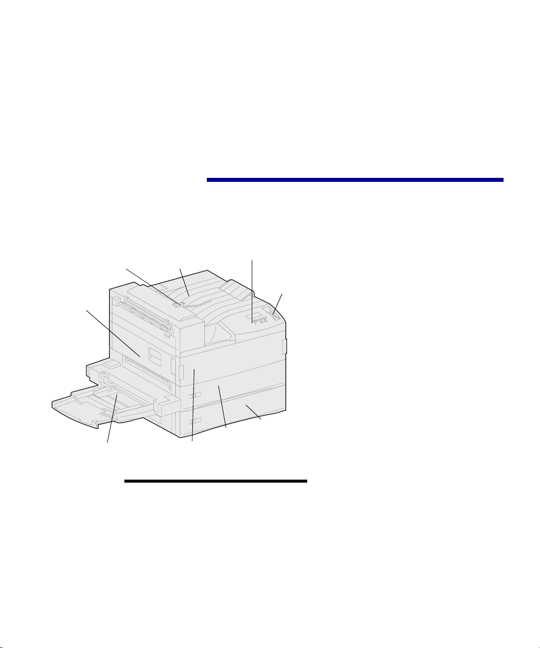
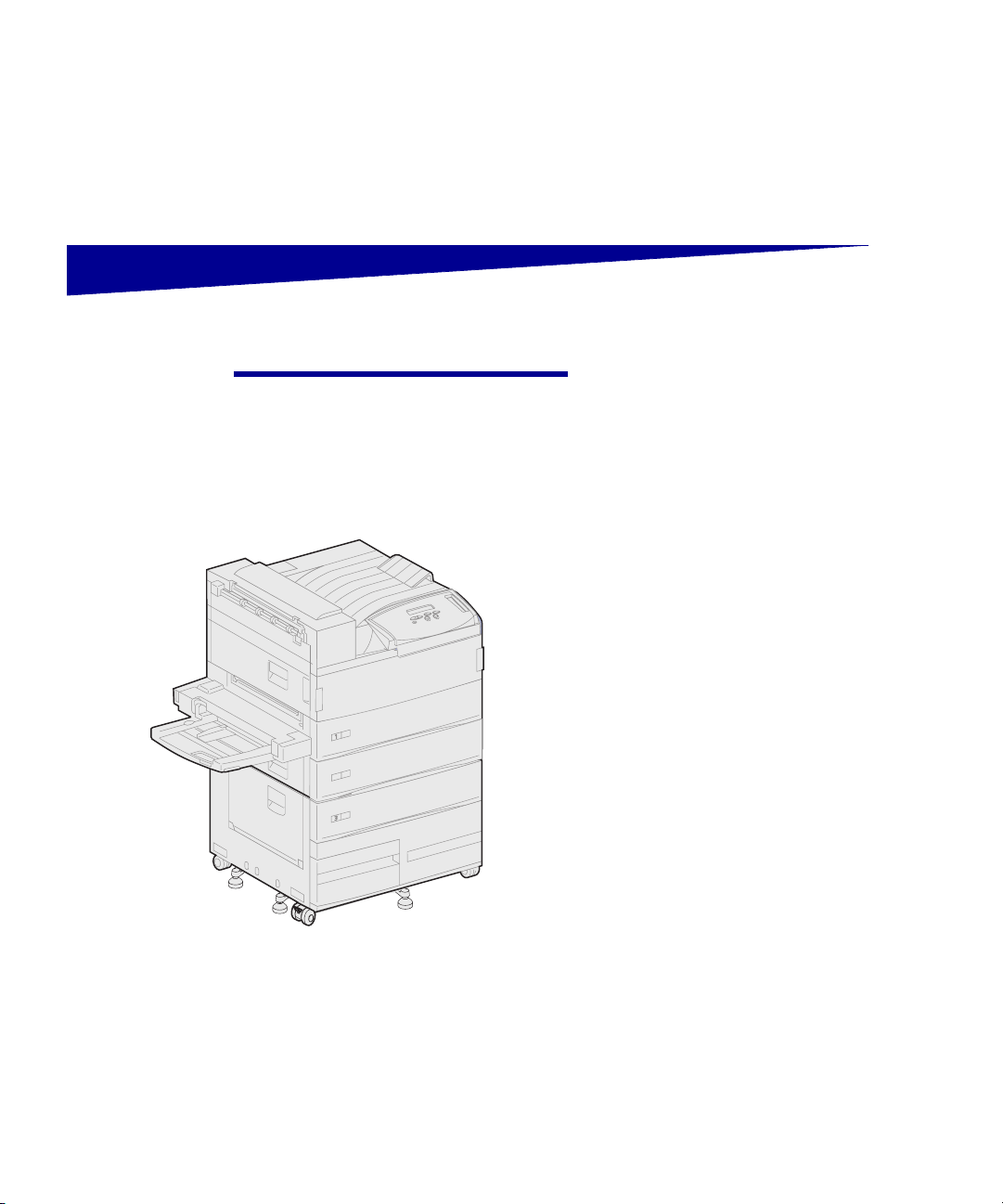
About your printer Three printer models are available:
Stacking arm
Jam access door
(Door A)
Multipurpose feeder
Tr a y 1
perator pane
Power
switch
Tray 2
Standard output bin
Front cover
(Door F)
Note: The illustrations in this manual
represent the Lexmark W820 model with
the optional high capacity feeder
installed, unless it is necessary to show
another configuration. Depending on the
printer model you have chosen and the
options you install, your printer may look
different.
• The Lexmark W820 printer,
delivering 600 dots per inch (dpi)
resolution at up to 45 pages per
minute (ppm), ships with two 500sheet trays. This model comes
with 32MB of standard memory.
• The Lexmark W820n, a network
model, comes with an Ethernet
10BaseT/100BaseTx print server
installed. This model comes with
64MB of standard memory.
• The Lexmark W820dn, a network
model that ships with a duplex unit
attached.
You may have purchased your
Lexmark W820 as part of a multifunction
device with capabilities such as copying,
faxing, or scanning. For information
about setting up components other than
the printer, refer to the documentation
that came with your multifunction device.
Preface
vii
Page 8
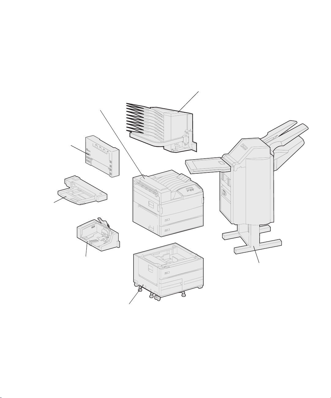
Lexmark W820
printer
Comes standard with
two 500-sheet trays.
Optional duplex unit
Lets you print on both
sides of a sheet of paper.
Multipurpose feeder
Lets you print without
using the printer trays.
Either the multipurpose
feeder or the optional
envelope feeder may be
attached to the printer.
The following figure illustrates the
Lexmark W820 and all the available
paper handling options. Instructions for
installing these options are included in
this book.
Optional 10-bin mailbox
Provides up to ten output bins for organizing
printed documents.
Either the optional mailbox or the optional
finisher may be attached to the printer.
viii
Optional envelope feeder
Lets you print envelopes without
manual feeding.
Either the optional envelope feeder
or the multipurpose feeder may be
attached to the printer.
Optional 2500-sheet high capacity feeder
Significantly increases the printer input capacity.
Either this feeder or a base cabinet may be attached to the printer.
Preface
Optional 3250-sheet finisher with
transport unit
Adds hole punching and stapling functions
to the printer output capabilities.
Either the optional finisher or the optional
mailbox may be attached to the printer.
Page 9

About this book
Note: See the safety information on the
inside front cover before setting up your
printer.
Conventions It may help you to recognize the note,
CAUTION! A caution identifies
something that might cause you harm.
Note: A note provides information you
may find useful.
This Setup Guide contains all the
information you need to set up your new
Lexmark W820, Lexmark W820n, or
Lexmark W820dn printer. This manual
provides detailed instructions for
unpacking and setting up the printer,
installing supplies and options, loading
media, launching the drivers CD to install
printer drivers and utilities, and printing
information from the Lexmark W820
Publications CD.
warning, and caution conventions we’ve
used in this book. These appear in the
left column for easy reference.
Warning! A warning identifies
something that might damage your
printer hardware or software.
Preface
ix
Page 10

Other sources of
information
Lexmark W820
Publications CD
Note: The Lexmark W820
Publications CD is located in the back
of this book. The information on the CD
is also available on the Lexmark Web
site at www.lexmark.com/publications.
Drivers CD The drivers CD contains all the
The Lexmark W820 Publications CD
provides information about loading
paper, clearing error messages, ordering
and replacing supplies, installing
maintenance kits, and troubleshooting. It
also provides general information for
administrators.
In the remainder of this book, the
Lexmark W820 Publications CD is
referred to as the “publications CD.”
necessary printer drivers to get your
printer up and running.
Depending on which version of the
drivers CD shipped with your printer, it
may also contain MarkVision™
Professional, other printer utilities, worldwide customer support phone numbers,
screen fonts, and additional
documentation.
These items and updates to the printer
drivers are also located on the Lexmark
Web site at www.lexmark.com.
x
Preface
Page 11

Quick Reference card The Quick Reference card provides easy
access to information about loading
paper, canceling a print job, printing
confidential jobs, and understanding
common printer messages.
Store the Quick Reference card in the
convenient printer pocket that attaches
to your printer.
Clearing Jams card The Clearing Jams card provides easy
access to information about clearing
print media jams in the printer and its
options.
Store the Clearing Jams card in the
convenient printer pocket that attaches
to your printer.
Lexmark Web site You can also access our Web site at
www.lexmark.com for updated printer
drivers, utilities, and other Lexmark
W820 printer documentation.
Preface
xi
Page 12

xii
Preface
Page 13

Step 1: Select a location
for your printer
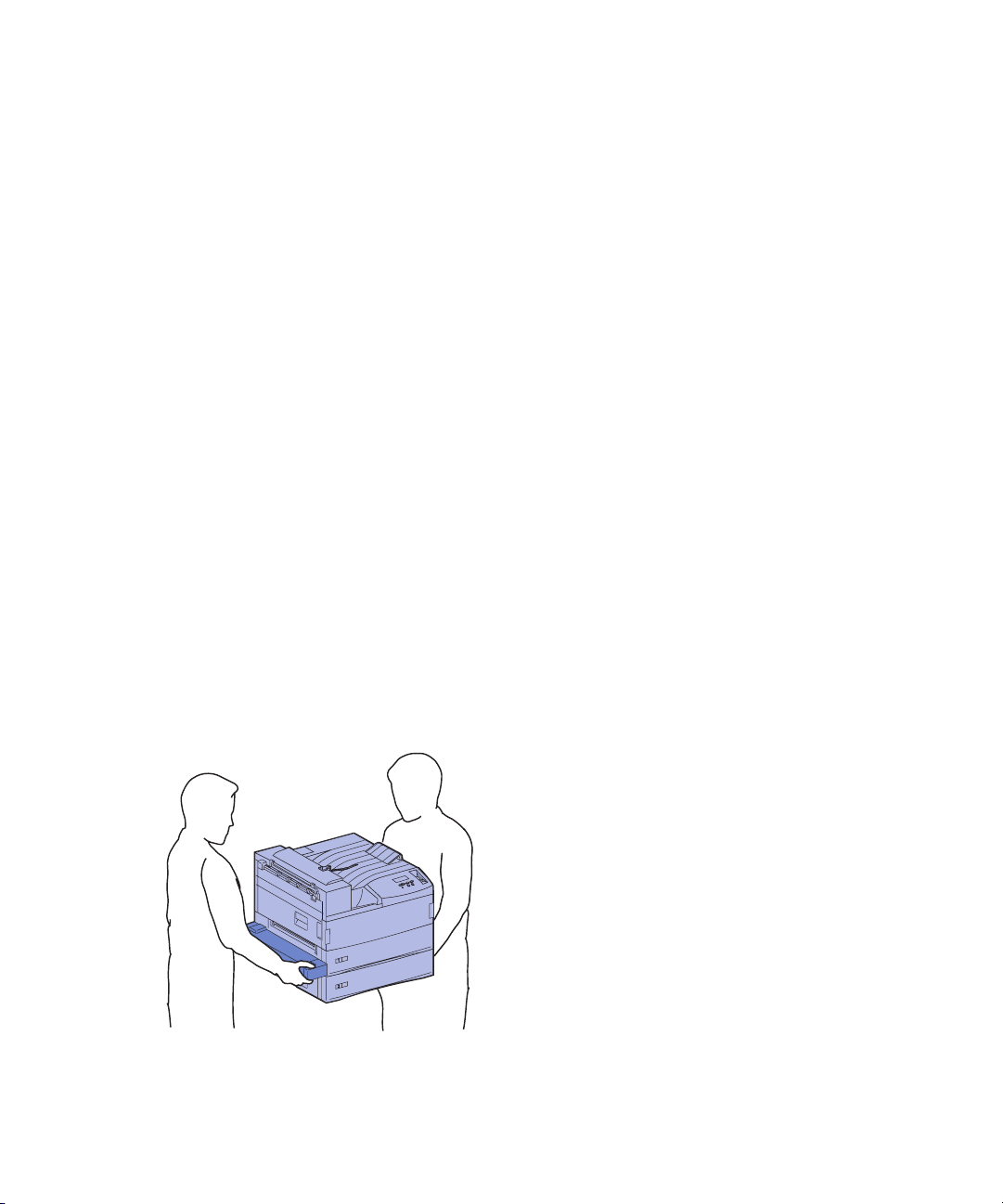
CAUTION! The printer weighs 46.8 kg
(103 lbs) and requires at least two
people to lift it safely.
Choosing the correct location for your
Lexmark™ W820 laser printer is vital to
ensuring that the printer provides you
with the quality of service you expect.
Some factors to consider when selecting
a place to set up your printer include:
• The amount of space your printer
and any options will require
• The type of environment
necessary for optimum printer
performance
Allowing enough space When choosing a place to set up your
printer, be sure to allow enough space
for the printer and any options you may
have purchased.
You will also need to leave enough room
to open the printer paper trays and side
doors, and to access any optional output
bins. It’s also important to allow space
for proper ventilation around the printer.
Select a location for your printer
1
Page 14
2
(
0
8
0
i
n
(
m
m
)
.
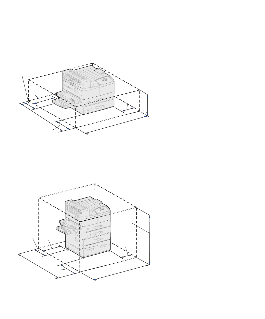
364 mm
(14 in.)
1
0
6
0
4
2
i
n
.
For a base printer When selecting a location for your
printer, make sure you have at least the
amount of space indicated in the figure.
2
0
0
m
m
(
n
8
i
.
)
m
m
)
m
m
0
6
4
8
1
(
)
.
n
i
m
m
4
8
0
1
)
.
n
i
3
4
(
700 mm
(28 in.)
With a duplex unit and
a high capacity feeder or
base cabinet
When selecting a location for a printer
with a high capacity feeder and duplex
unit, make sure you have at least the
amount of space indicated in the figure.
If you install a base cabinet rather than a
high capacity feeder, your printer will
require the same amount of space as
shown in the figure.
1220 mm
(48 in.)
2
0
0
(
8 i
n.)
1
(
4
2
364 mm
m
m
(14 in.)
0
6
0
m
i
n
.
)
4
6
0
(
m
1
m
8
m
i
n
.
)
200 mm
(8 in.)
4
8
0
1
n
i
3
4
(
m
m
)
.
2
Select a location for your printer
Page 15
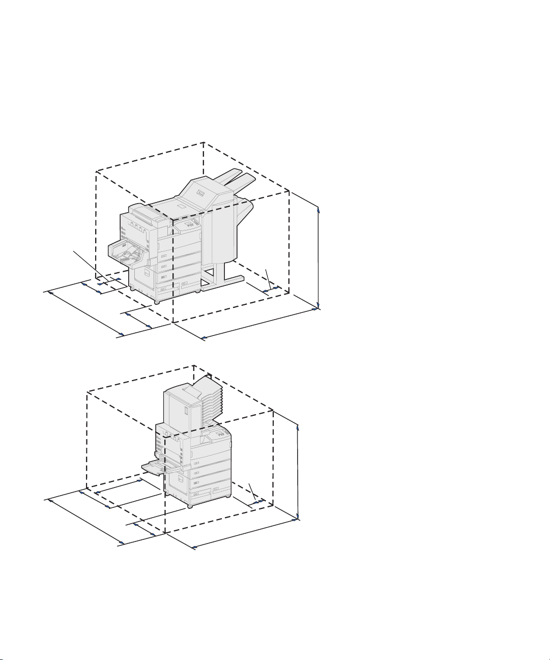
With finisher or mailbox When selecting a location for a printer
with a finisher or mailbox, make sure you
have at least the amount of space
indicated in the figure.
364 mm
(14 in.)
(
8
1
0
6
0
(
4
2
i
n
.
)
(
1
0
6
(
0
4
2
i
n
6
3
0
(
m
2
5
m
i
n
.
)
2
0
0
m
m
i
n
.
)
4
m
m
2
0
8
i
n
m
.
)
6
0
(
m
1
8
m
in
.
)
mm
4
6
3
)
.
n
i
4
1
0
m
(
m
m
.
)
4
6
0
(
1
m
8
m
i
n
.
)
2
(
2
0
0
(
8
n
i
8
0
1
3
4
(
m
m
9
6
0
)
.
n
i
1
8
m
m
)
.
m
m
4
)
.
n
i
1520 mm
(60 in.)
1700 mm
(67 in.)
Select a location for your printer
3
Page 16
Considering
environmental issues
When choosing a place to set up the
printer, make sure the location you select
is:
• A firm, level surface where the
printer won’t be subjected to
strong vibration
• Well ventilated
• Away from the direct airflow of air
conditioners, heaters, or
ventilators
• Free of temperature or humidity
extremes or fluctuations
• Clean, dry, and free of dust
• Away from direct sunlight
Moving the printer At some point in the future you may
decide to move the printer to a new
location. The publications CD provides
details about removing options before
moving the printer.
If you’re going to move the printer, keep
the following in mind:
• Because the printer is heavy
(approximately 46.8 kg [103 lbs]),
two people are required to lift it
safely.
• Remove the print cartridge before
you move the printer. If the printer
is moved with the cartridge
installed, toner may spill out and
damage the printer.
• Be sure to plug the printer into a
properly grounded outlet in the
new location.
4
Select a location for your printer
Page 17
Step 2: Unpack the printer
Now that you have chosen a location for
your Lexmark W820, you are ready to
unpack the printer and prepare to set it
up.
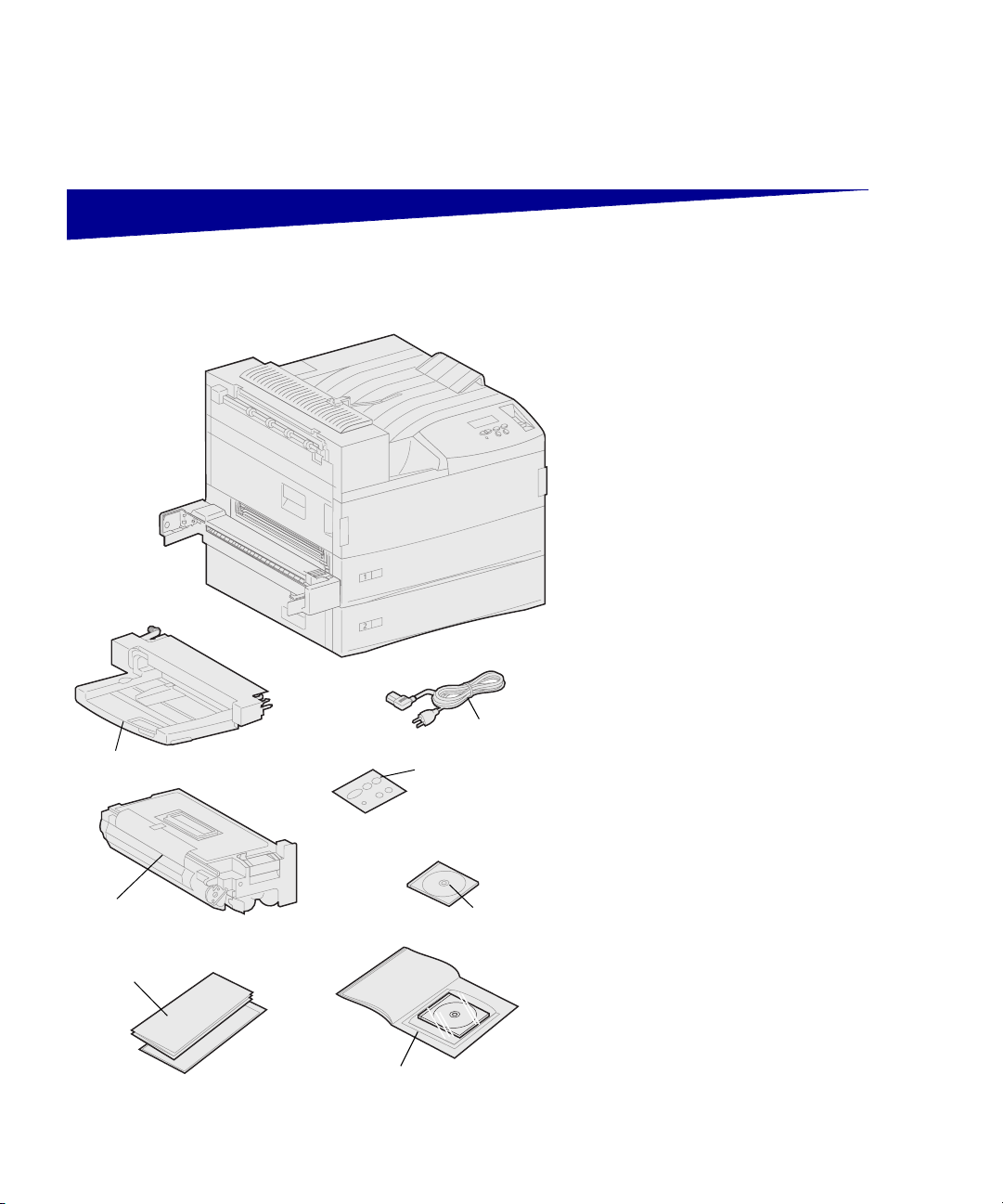
Make sure you have the following items:
• Printer with two 500-sheet
drawers
• Multipurpose feeder
• Power cord
• Print cartridge
• Setup Guide with a Lexmark
W820 Publications CD
The publications CD is located in
the back of this book.
Multipurpose feeder
Power cord
Operator panel overlay
(non-English only)
• Quick Reference card, Clearing
Jams card, and printer pocket
• Drivers CD
Print cartridge
Quick Reference card, Clearing Jams card,
and printer pocket
Drivers CD
Setup Guide with Lexmark
W820 Publications CD
• Operator panel overlay
(non-English only)
If any items are missing or damaged,
refer to the publications CD for the
designated Lexmark support phone
number for your country.
Save the carton and packing material in
case you need to repack the printer.
Unpack the printer
5
Page 18

Step 3: Install the
multipurpose feeder
Note: If you will be attaching the
optional envelope feeder during setup,
skip this step and continue with either
Step 4: “Set up the optional
high capacity feeder” on page 9 or
Step 5: “Set up printer supplies” on
page 17.
CAUTION! If you are installing the
multipurpose feeder sometime after
setting up the printer, turn the printer off
and unplug the power cord before
continuing.
Note: You can install the multipurpose
feeder with or without the duplex unit
already attached to the printer.
Your printer comes with a multipurpose
feeder that can be used to load paper,
transparencies, labels, or card stock.
The multipurpose feeder holds
approximately 35 sheets of paper.
To install the multipurpose feeder:
1 Hold the multipurpose feeder by
both sides.
6
Install the multipurpose feeder
Page 19
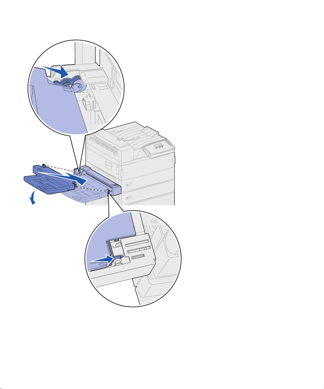
2 Tilt the feeder end going into the
printer first down slightly, as you
align the posts on the feeder with
the holes above the opening in the
printer.
Make sure the top of the feeder
fits over the top of the edge
coming out of the printer. (See the
illustration on page 8.)
Install the multipurpose feeder
7
Page 20
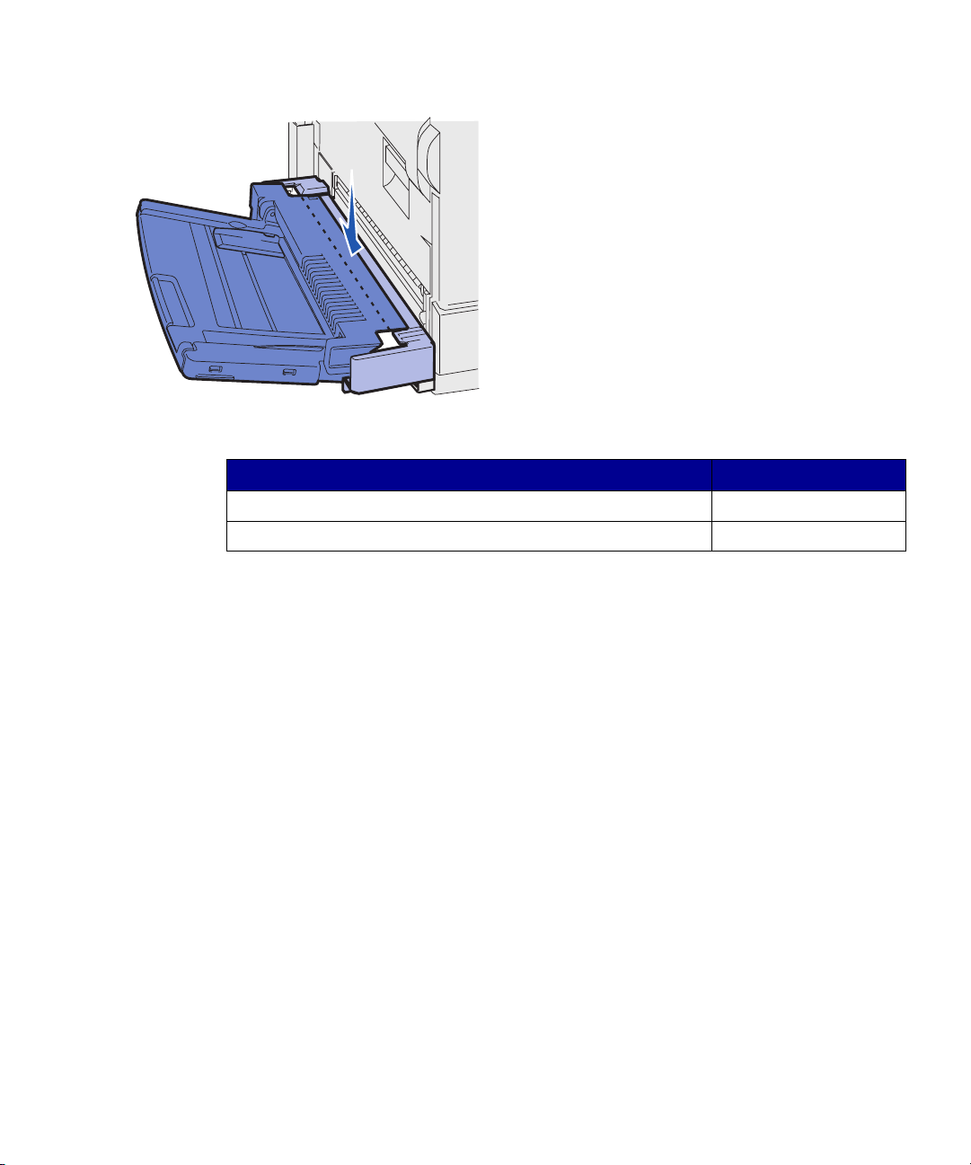
3 Gently insert the feeder at this
angle into the opening and then
drop it down into place. The
feeder should be firmly in place.
What do I do next?
Task Go to page…
Set up the optional high capacity feeder or base cabinet 9
Set up printer supplies 17
8
Install the multipurpose feeder
Page 21
Step 4: Set up the optional
high capacity feeder
CAUTION! If you are installing a high
capacity feeder sometime after setting
up the printer, turn the printer off and
unplug the power cord and any other
cables before continuing.
Your printer supports either an optional
high capacity feeder or an optional
base cabinet.
The high capacity feeder contains one
500-sheet tray and two 1000-sheet trays
for a total capacity of 2500 sheets of
print media. The base cabinet is optional
furniture that is the same size and shape
as the high capacity feeder. It provides
storage space while aligning an optional
mailbox or finisher with the printer.
Set up the optional high capacity feeder
9
Page 22
To set up the high capacity feeder or
base cabinet:
Warning! Lift the high capacity feeder
from the bottom.
High capacity feeder
Warning! Be sure you remove the
sheets of foam packing from the bottom
of both trays before you print from the
high capacity feeder.
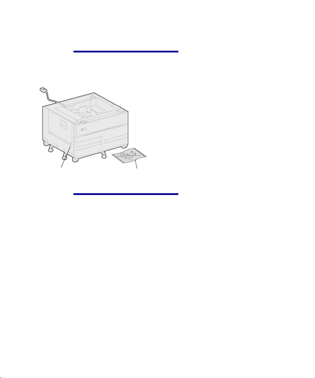
1 Remove the high capacity feeder
or cabinet from its packing
materials.
Locking clips, thumbscrews,
and tray labels
Be sure to remove the foam
packing and tape from the trays.
Save the carton and packing
materials in case you need to
repack the option.
10
2 Make sure you have the following
items:
— 2500-sheet high capacity
feeder or base cabinet
— 2 locking clips
— 2 thumbscrews
— tray labels
Set up the optional high capacity feeder
Page 23
Attaching a high
capacity feeder or
base cabinet
CAUTION! The printer weighs 46.8 kg
(103 lbs) and requires at least two
people to lift it safely.
The steps in this section explain how to
connect your printer to a high capacity
feeder. When the steps for a base
cabinet are different, a note to the left of
the step provides the necessary
information.
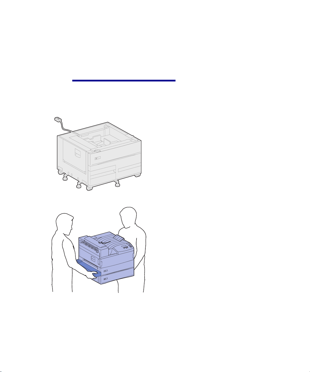
1 Make sure the high capacity
feeder cable is situated in the
notch on the back of the feeder.
2 Have someone help you lift the
printer.
— Person 1: Grasp the printer on
the right side by the
handholds.
— Person 2: Grasp under the
printer where the multipurpose
feeder attaches.
Set up the optional high capacity feeder
11
Page 24
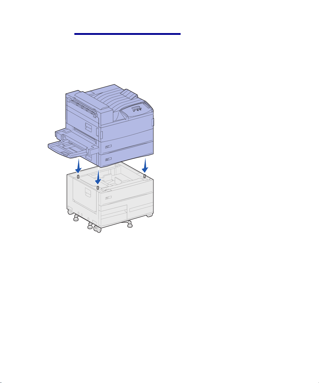
Warning! Do not slide the printer
across the high capacity feeder to
position it.
3 Carefully place the printer on top
of the high capacity feeder. Make
sure the trays on the printer are
lined up on the same side as the
trays on the high capacity feeder.
Be sure to align all four corners on
the bottom of the printer with the
corners on the top of the high
capacity feeder. Small metal pins
on the top of the high capacity
feeder fit into grooves on the
bottom of the printer.
12
Set up the optional high capacity feeder
Page 25
Attaching the locking clips The locking clips keep the printer and
the high capacity feeder properly
aligned, helping to prevent them from
being separated accidently.
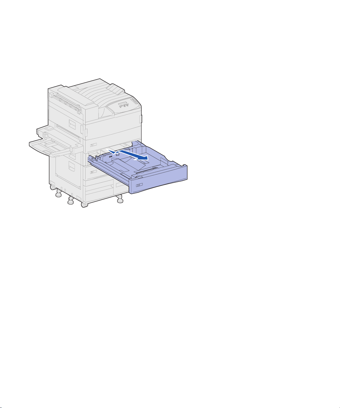
1 Remove tray 2.
a Pull the tray out fully.
b Tilt the front of the tray upward.
c Gently pull the tray out.
Set up the optional high capacity feeder
13
Page 26
Note: If you are installing a base
cabinet, open the cabinet door.
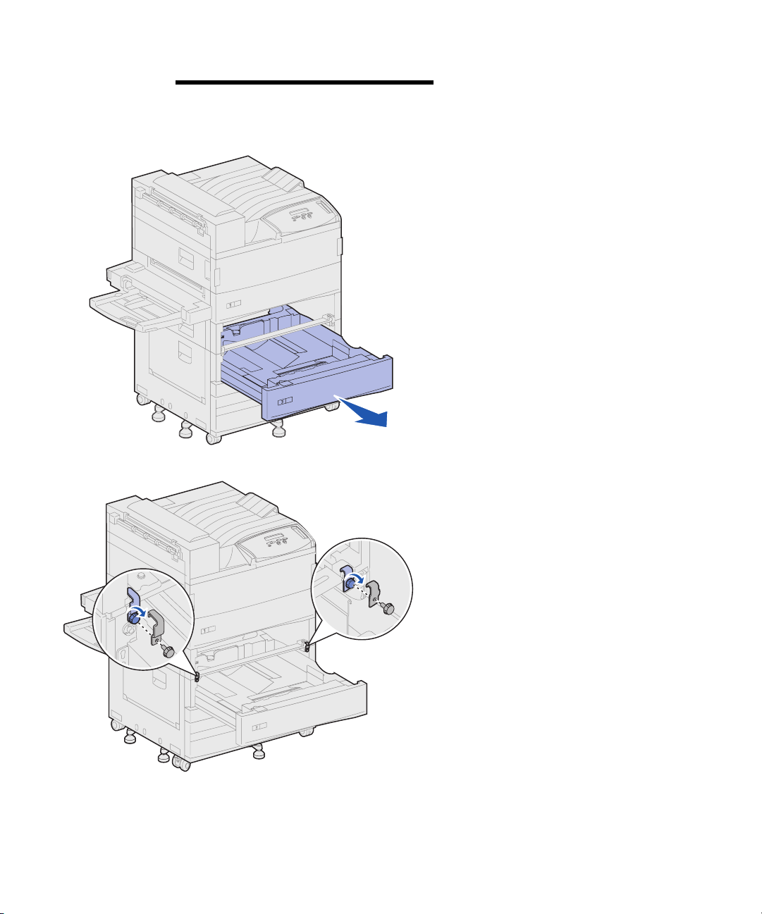
2 Open tray 3.
3 Attach the locking clips to the left
and right sides of the trays.
14
4 Secure the locking clips using the
thumbscrews.
Set up the optional high capacity feeder
Page 27
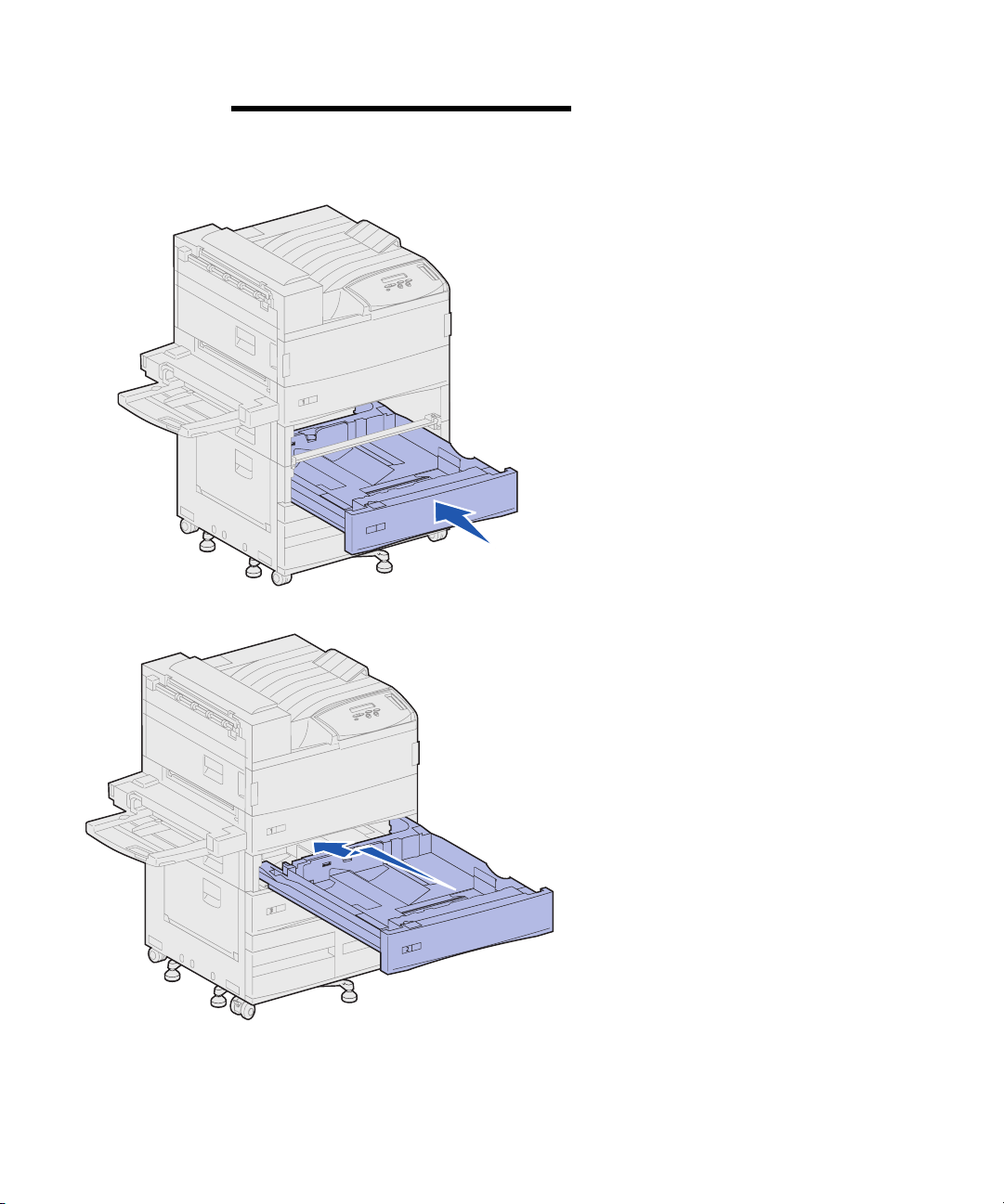
Note: If you are installing a base
cabinet, close the cabinet door.
5 Close tray 3.
6 Reinsert tray 2.
Set up the optional high capacity feeder
15
Page 28
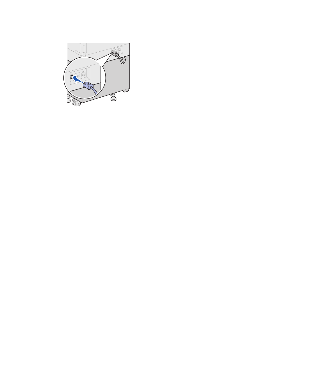
7 At the back of the printer, plug the
high capacity feeder cable into the
connector labeled “Tr ay ” on the
printer.
16
Set up the optional high capacity feeder
Page 29
Step 5: Set up printer supplies
You have unpacked your printer and
chosen a location for it. Now you are
ready to set up supplies.
Door A
Installing the
print cartridge
Door F
Each print cartridge supports
approximately 30,000 pages of singlesided printing, depending on the types of
jobs you print and the amount of toner
required for each page. The printer
displays a message when it is time to
replace the cartridge. You may want to
keep a supply of print cartridges handy.
Refer to the publications CD for details.
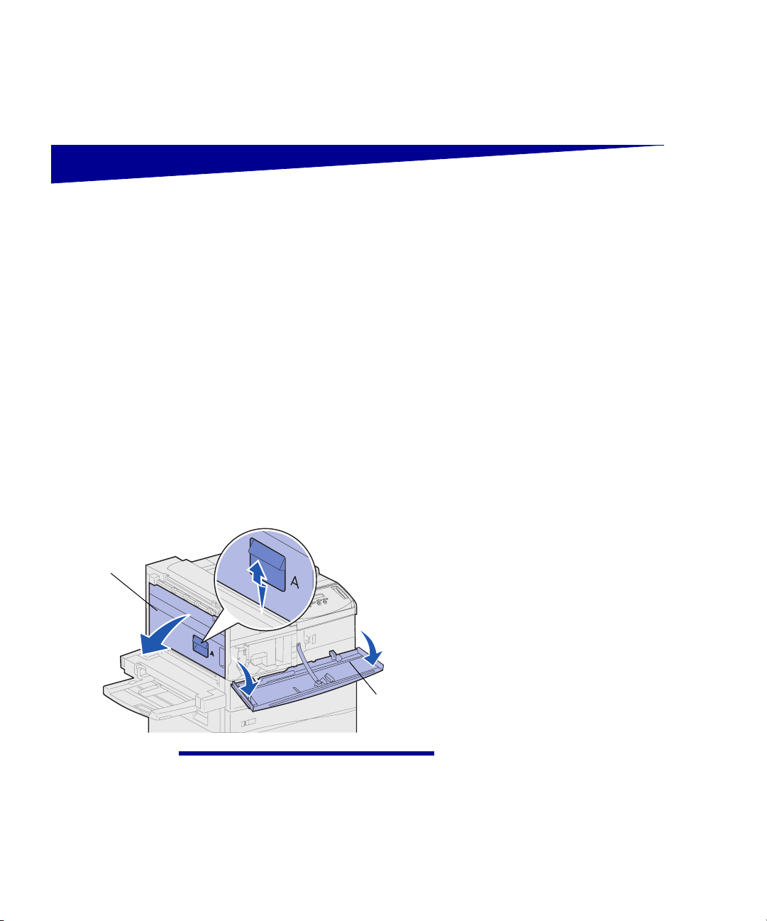
To install the print cartridge:
1 Open the printer side and front
doors (Doors A and F).
2 Remove the print cartridge from
its packing materials.
Warning! Do not remove the yellow
tape from the print cartridge at this point.
3 Turn the cartridge so that the
handle is on top.
Set up printer supplies
17
Page 30
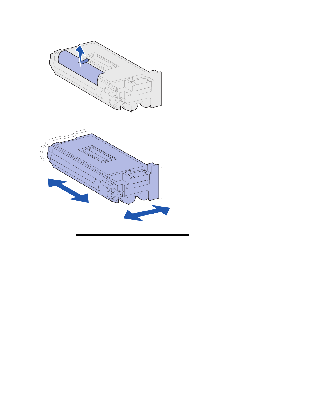
4 Remove the tape (on the top of
the cartridge) and then gently pull
the protective paper straight up
and out of the cartridge.
5 Shake the cartridge vigorously in
all directions to distribute the
toner.
18
Note: If toner spills on the floor, do not
clean it up using a vacuum or a wet
cloth. Wipe up the spill with a dry cloth. If
toner gets on clothing, be sure to wash
the clothing in cold water.
Set up printer supplies
Page 31

6 Holding the print cartridge by the
handle and one end, align the
cartridge with the slots inside the
printer.
7 Slide the cartridge into the printer
as far as it will go until it snaps into
place.
Set up printer supplies
19
Page 32

8 Carefully pull the yellow tape
completely out of the cartridge.
Discard the tape.
9 Close the front door (Door F).
Door F
Preparing the fuser The fuser supports approximately
300,000 pages of single-sided printing.
The printer displays a message when it
is time to replace the fuser. Refer to the
publications CD for details.
20
Note: You need a coin or a flat blade
screwdriver for the following steps.
Set up printer supplies
You must remove the two metal screws
on each side of the fuser before
operating the printer; otherwise, print
quality will be diminished.
Page 33

1 Remove the two labels covering
the screws on each side of the
fuser.
2 Turn each screw one third turn
counterclockwise.
3 Pull both screws straight out and
then discard them.
Door A
4 Close the side door (Door A).
Set up printer supplies
21
Page 34

Applying the
operator panel overlay
(non-English only)
What do I do next?
If English is not your preferred language,
attach the overlay with the translated
button names to the printer operator
panel.
1 Locate the overlay packaged with
your printer.
2 Peel the protective backing off the
overlay.
3 Align the holes in the overlay with
the buttons on the operator panel,
and then press it into place.
4 Peel the protective covering away
from the overlay.
Yo u ’ll find instructions for changing the
language of the menus and messages
displayed on the operator panel display
in the publications CD.
22
Task Go to page…
Install memory and option cards 23
Install the optional duplex unit 34
Secure the wheels and leveling feet 37
Set up printer supplies
Page 35

Step 6: Install memory and
option cards
You can customize your printer memory
capacity and connectivity by adding
optional cards.
The instructions in this section help you
install any of the following options:
• Printer memory
• Flash memory
• Tri-Port Adapter
• USB/Parallel 1284-C Interface
Card
• Parallel 1284-C Interface Card
• MarkNet™ internal print servers
(also called internal network
adapters or INAs)
• Hard disk
• Optional firmware card
Install memory and option cards
23
Page 36

Accessing the printer
system board
CAUTION! If you are installing memory
or option cards sometime after setting up
the printer, turn the printer off and unplug
the power cord and any other cables
before continuing.
What do I do next?
Tas k Go to page…
Installing memory cards 25
1 Locate the metal plate on the back
of the printer.
2 Loosen the two thumbscrews.
The thumbscrews do not come
completely off the plate.
3 Gently pull the thumbscrews until
you can grasp the system board.
4 Pull the system board out just far
enough to access the connector
slots.
Do not fully remove the board
from the printer.
24
Installing an optional firmware card 28
Installing option cards 30
Install memory and option cards
Page 37

Installing
memory cards
Follow the instructions in this section to
install either a printer memory card or a
flash memory card. The system board
has three connectors for optional
memory cards. You can install any
combination of printer memory and flash
memory cards in the three connectors.
However, the printer only recognizes one
flash memory card at a time.
Note: Some memory options for other
Lexmark printers cannot be used with
your printer.
Memory connectors
Latches
1 Access the system board. (See
page 24 for instructions.)
2 Locate the memory connectors on
the system board.
Each connector can support
either a printer memory card or a
flash memory card.
3 Push open the latches on both
ends of the connector you want to
use.
Install memory and option cards
25
Page 38

Warning! Printer memory and flash
memory cards are easily damaged by
static electricity. Touch something metal
on the printer before you touch a
memory card.
Connection points
4 Unpack the memory card.
Avoid touching the connection
points along the edge of the card.
Save the packaging.
5 Align the notches on the bottom of
the card with the notches on the
connector.
26
Install memory and option cards
Page 39

Notch
Warning! Support the bottom of the
system board when installing a card.
6 While holding the system board
from the bottom, push the
memory card firmly into the
connector until the latches on
either end of the connector snap
into place.
Notch
It may require some force to fully
seat the card.
Make sure each latch fits over the
notch on the end of the card.
7 Repeat steps 4 through 6 to install
other memory cards.
What do I do next?
Tas k Go to page…
Installing an optional firmware card 28
Installing option cards 30
Reinstalling the system board 33
Install memory and option cards
27
Page 40

Installing an optional
firmware card
Note: Firmware options offered for
other Lexmark printers cannot be used
with your printer.
Follow the instructions in this section to
install an optional firmware card. The
system board has one location where
firmware cards can be installed.
Warning! Optional firmware cards are
easily damaged by static electricity.
Touch something metal on the printer
before you touch a card.
Resting posts
Pins
1 Access the system board. (See
page 24 for instructions.)
2 Unpack the firmware card.
Avoid touching the metal pins on
the bottom of the card. Save the
packaging.
28
Install memory and option cards
Page 41

System board holes
Warning! Support the bottom of the system board.
3 Holding the firmware card by its
sides, align the two pins on the
card with the holes on the system
board.
Orient the card as shown.
4 While holding the system board
from the bottom, push down until
the firmware card is firmly in
place.
The entire length of the plastic
connector on the firmware card
must touch the system board.
Some force may be required to
fully install the card, but be careful
not to damage the card’s
connectors.
What do I do next?
Tas k Go to page…
Installing option cards 30
Reinstalling the system board 33
Install memory and option cards
29
Page 42

Installing option cards Your printer has two connectors that
support the following option cards:
Note: The Lexmark W820n and
Lexmark W820dn printers ship with an
Ethernet print server already installed.
Install a hard disk with adapter
card to add additional storage
space to your printer.
Install a MarkNet N2501e or N2401e internal
print server if you received either of these cards
as part of a multifunction printer upgrade.
Install a MarkNet internal print
server to add an Ethernet or TokenRing port for connecting your
printer to a network.
• Hard disk with adapter card
• MarkNet internal print server
• USB/Parallel 1284-C Interface
Card
• Parallel 1284-C Interface Card
• Coax/Twinax Adapter for SCS
• Tri-Port Adapter
You need a small Phillips screwdriver to
install these options.
Install a USB/Parallel 1284-C or
a Parallel 1284-C Interface Card
to add a Universal Serial Bus
(USB) port or a parallel port.
30
Install memory and option cards
Install a Tri-Port Adapter to add
LocalTalk, serial, and infrared ports.
For details on setting up and using
the Tri-Port Adapter, refer to the
documentation that shipped with
the card.
Page 43

Option card connectors
Note: If you are installing two option
cards, install the first one in the lower
option card connector, so it will be easier
to install the second card.
Complete the following steps to install
any of the option cards mentioned on
page 30:
1 Access the system board (see
page 24 for instructions) and
locate the option card connectors.
Warning! Install hard disks in the top
connector slot only. This prevents
overheating.
Connector slot
2 Remove the metal plate covering
the connector slot.
a Remove the screw on the right
end of the metal plate.
Save the screw.
b Remove the metal plate by
pulling it to the right.
Install memory and option cards
31
Page 44

Warning! Option cards are easily
damaged by static electricity. Touch
something metal on the printer before
you touch an option card.
3 Unpack the option card.
Save the packing materials.
4 Align the connector on the option
card with the connector on the
system board.
The cable connectors on the side
of the option card must fit through
the connector slot.
5 Push the option card firmly into
the option card connector.
6 Secure the card to the system
board metal plate with two screws.
7 Repeat steps 2 through 7 to install
another option card.
32
Install memory and option cards
Page 45

Reinstalling the
system board
1 Gently push the system board
back into the printer.
2 Tighten the two thumbscrews.
3 Reconnect any previously
connected cables on the back of
the printer.
What do I do next?
Task Go to page …
Install the optional duplex unit 34
Secure the wheels and leveling feet 37
Install memory and option cards
33
Page 46

Step 7: Install the optional
duplex unit
Extendable bracket
CAUTION! If you are installing the
duplex unit sometime after initial printer
setup, turn the printer off and unplug the
power cord before continuing.
Note: If you are installing the duplex
unit after having previously installed the
optional envelope feeder, the envelope
feeder must be removed before installing
the duplex unit. Refer to the publications
CD for help.
Your printer supports an optional duplex
unit that lets you print on both sides of a
sheet of paper.
To install the duplex unit:
1 Make sure the multipurpose
feeder is open (down position).
2 Remove the duplex unit from its
packaging.
Be sure to remove the packaging
from under the plastic grid.
There are three metal brackets on
the duplex unit: two stationary
brackets and one extendable
bracket.
34
Stationary brackets
Install the optional duplex unit
Page 47

3 Hold the duplex unit as shown.
4 Attach the duplex unit to the top of
the multipurpose feeder.
a Holding the duplex unit parallel
with the ground, attach the two
stationary metal brackets on
the duplex unit to the metal
rods on the top of the
multipurpose feeder.
b Tilt the duplex unit toward the
printer until the extendable
metal bracket on the right
snaps into place.
5 Pull out the cable on the left side
of the duplex unit and fully extend
it.
6 Attach the cable hook to the metal
eye on the printer.
Install the optional duplex unit
35
Page 48

7 Close the duplex unit by pushing it
toward the printer until it latches
into place.
8 Plug the duplex unit cable into the
connector labeled “Duplex” on the
back of the printer.
36
Note: When the duplex unit is in
operation, the printer partially ejects
paper, then draws it back into the duplex
unit before it is fully ejected. Do not
remove paper before it is completely
ejected or a paper jam may result.
Install the optional duplex unit
Page 49

Step 8: Secure the wheels and
leveling feet
Note: This only applies if you have a
high capacity feeder or a base cabinet
attached to the printer.
Once you have all the printer
components attached and the printer is
positioned where you want it, you need
to stabilize it.
1 Lock the wheels by pushing down
on the lever attached to them.
2 Rotate all the leveling feet until
they touch the ground.
Secure the wheels and leveling feet
37
Page 50

What do I do next?
Task Go to page…
Set up the optional mailbox 39
Set up the optional finisher 53
Install the optional envelope feeder 71
Load print media 73
38
Secure the wheels and leveling feet
Page 51

Step 9: Set up the
optional mailbox
Note: The printer can support either a
mailbox or a finisher, but not both at the
same time.
Your printer supports an optional10-bin
mailbox that helps you organize your
printed documents.
Before you can attach a mailbox, you
must install either a high capacity feeder
or a base cabinet. For help setting up a
high capacity feeder or a base cabinet,
see page 9.
Note: The illustrations in this section
show the printer with a high capacity
feeder attached.
Set up the optional mailbox
39
Page 52

Removing the
stacking arm
Stacking arm
CAUTION! If you are installing the
mailbox sometime after initial printer
setup, turn the printer off and unplug the
power cord before continuing.
Before you can attach a mailbox, you
must remove the stacking arm from the
printer.
To remove the stacking arm, push the
tab on the top of the arm toward the
printer output bin until it snaps loose. Be
sure to save the stacking arm so you can
reattach it if you remove the mailbox.
40
Set up the optional mailbox
Page 53

Unpacking the mailbox
CAUTION! The mailbox weighs 15.9 kg
(35 lbs) and requires two people to lift it
safely.
Warning! The mailbox must be set
down with the door (Door F) facing the
ground. Otherwise, the mailbox may be
damaged.
Door F
1 Remove the mailbox and all other
items from their packaging.
Be sure to set the mailbox down
with Door F toward the ground.
Remove any plastic wrapping,
shipping tape, and protective
foam.
Save the carton and packing
materials in case you need to
repack the mailbox.
Set up the optional mailbox
41
Page 54

Paper stop
Thumbscrews
Mailbox
Upper portion of
mailbox stand
2 Make sure you have the following
items:
— Mailbox with 10 output bins
and handling tool
— Mailbox stand:
-- Upper portion stand piece
-- 2 side stand pieces
-- Side stand bracket
— Stabilizing foot with L-pin
— 3 thumbscrews
— Paper stop
If any items are missing or
damaged, refer to the drivers CD
for the designated Lexmark
support phone number for your
country.
L-pin
Side stand bracket
Side stand pieces
Stabilizing foot
42
Set up the optional mailbox
Page 55

Attaching the
mailbox stand
1 Position the side stand pieces so
that the small metal knobs are
toward the sides of the printer, as
shown.
2 Insert the knobs into the slots in
the printer.
3 Slide the side stand pieces down
until they rest firmly in place.
Set up the optional mailbox
43
Page 56

4 Position the side stand bracket,
connecting the printer and the
stabilizer bar.
a Position the bracket on the
underside of the printer, on the
same side as the side stand
with the stabilizer bar.
44
Set up the optional mailbox
Page 57

b Slide the bracket so that the
top fits over the stabilizer bar.
Align the hole in the bracket
with the hole in the stabilizer
bar.
c Insert the small thumbscrew
through the bracket and
stabilizer bar, and then tighten.
Set up the optional mailbox
45
Page 58

5 Insert a thumbscrew through the
hole in the middle of each side
stand piece, and then tighten the
screws.
6 Slide the stabilizing foot over the
high capacity feeder back foot.
If the high capacity feeder back
foot is completely lowered,
especially on a carpeted surface,
you may need to raise it off the
ground before the stabilizing foot
will properly fit over it.
46
Set up the optional mailbox
Page 59

7 Insert the L-pin through the holes
in the stabilizing foot and back
foot.
8 Rotate the end of the L-pin down
into the slot in the stabilizing foot.
Set up the optional mailbox
47
Page 60

Warning! Make sure the upper portion
is oriented correctly, with the taller side
on the same end of the printer as the
multipurpose feeder.
9 Slide the upper portion of the
stand down into the side stands
until it snaps into place.
48
Set up the optional mailbox
Page 61

Positioning the mailbox
CAUTION! The mailbox requires two
people to lift it safely.
Note: Be sure the mailbox cord is
between the printer and the stand when
you lower the mailbox. Do not pinch the
cord as you position the mailbox.
Horizontal bar
Mailbox
post
Metal
Divertor Gate G
pin
1 Be sure you have removed the
stacking arm from the printer.
(See “Removing the stacking arm”
on page 40).
2 Have someone help you lift the
mailbox, using the horizontal bar
and the handling tool on the
opposite side.
3 Align the mailbox post with the
stand rail.
Handling tool
Stand rail
Warning! Do not rest the mailbox on
Divertor Gate G when seating the
mailbox.
4 Carefully lower the mailbox onto
the stand.
Align the metal pin on the stand
with the hole in the mailbox post.
The mailbox is fully seated on the
stand rail when properly installed.
Set up the optional mailbox
49
Page 62

Lever
Storing the
handling tool
1 Remove any tape from the
mailbox door (Door D).
2 Open the mailbox door.
3 Remove any tape from the
handling tool.
4 While pressing down on the small
lever, push the tool handle down
and toward the mailbox door.
50
The handling tool is released from
the mailbox.
5 Close the mailbox door.
Set up the optional mailbox
Page 63

Indentation
Stand rail
6 Move to the back of the printer
where the mailbox stand rail is
located.
7 Align the tool handle with the
indentation on the mailbox while
aligning the metal portion of the
tool with the slot in the stand.
8 Slide the tool toward the mailbox
until the tool snaps into place.
Slot
Attaching the
metal paper stop
1 Insert the lower end of the metal
paper stop in the hole on the
bottom mailbox output bin.
2 Gently separate the top two
mailbox bins and insert the upper
end of the paper stop in the hole
on the top bin.
3 Rotate the paper stop so that it
rests against the bins.
If the paper stop does not easily
rest next to the bins, it may be
upside down. Make sure it is
oriented as shown.
Set up the optional mailbox
51
Page 64

Plugging in the mailbox
CAUTION! Make sure the printer is
unplugged before continuing.
Plug the communication cable from the
mailbox into the connector labeled
“Output” on the back of the printer.
52
What do I do next?
Task Go to page…
Install the optional envelope feeder 71
Load print media 73
Set up the optional mailbox
Page 65

Step 10: Set up the
optional finisher
Note: The printer can support either a
mailbox or a finisher, but not both at the
same time.
Your printer supports an optional finisher
that adds hole punching and stapling
functions to the printer output
capabilities.
Before you can attach a finisher, you
must install either a high capacity feeder
or a base cabinet. For help setting up a
high capacity feeder or a base cabinet,
see page 9.
Note: The illustrations in this section
show the printer with a high capacity
feeder attached.
Set up the optional finisher
53
Page 66

Removing the
stacking arm
Stacking arm
Before you can attach a finisher, you
must remove the stacking arm from the
printer.
To remove the stacking arm, push the
tab on the top of the arm toward the
printer output bin until it snaps loose. Be
sure to save the stacking arm so you can
reattach it if you remove the finisher.
54
Set up the optional finisher
Page 67

Unpacking the finisher
Ta b s
CAUTION! If you are installing the
finisher sometime after initial printer
setup, turn the printer off and unplug the
power cord before continuing.
Metal locking bracket
1 Remove the cardboard box by
lifting it straight up and setting it to
the side.
2 Remove the foam from the top of
the finisher and by the legs.
3 Lightly press on the tabs located
on the metal locking brackets near
each leg, and move both brackets
toward the middle of the finisher.
Set up the optional finisher
55
Page 68

4 Lift the bottom of the finisher up
slightly and extend the legs fully
until you see molded arrows on
the inside of the legs.
Be sure to align the holes in the
legs with the pins on the locking
brackets.
5 Push the locking brackets back
into place.
56
Set up the optional finisher
Page 69

CAUTION! The finisher weighs 44.1 kg
(97 lbs) and requires at least two people
to lift it safely.
6 Have someone help you lift the
finisher to the upright position.
7 Remove any plastic wrapping and
shipping tape.
Be sure to note the tape in the
places shown.
Set up the optional finisher
57
Page 70

Staple head
locking plate
Warning! The staple head locking plate
is used for shipping purposes only. If it is
not removed, the stapling unit can not
function and an error will occur.
8 Remove the two wingnuts holding
the metal staple head locking
plate.
9 Slide the plate up and remove it.
Discard the plate and wingnuts.
10 Remove the other items from their
packaging.
Remove any plastic wrapping.
Save the carton and packing
materials in case you need to
repack the finisher.
58
Wingnuts
Set up the optional finisher
Page 71

Divertor cover
Thumbscrews
Transport unit
Finisher
Communication cable
Finisher
plate
Output bin 1
Output bin 2
Power cable
11 Make sure you have the following
items:
— Finisher
— Output bins 1 and 2
— Finisher plate
— Guide rail
— Guide rail holding plate
— Transport unit
— Transport unit brackets
— Thumbscrews
— Divertor cover
— Communication cable
— Power cabl e
If any items are missing or
damaged, refer to the drivers CD
for the designated Lexmark
support phone number for your
country.
Transport
unit
brackets
Guide rail
holding plate
Guide rail
Set up the optional finisher
59
Page 72

Attaching the
transport unit brackets
1 Attach the two metal transport unit
brackets to the back of the finisher
using the four thumbscrews.
60
Set up the optional finisher
Page 73

Attaching the
finisher plate
and guide rail
Finisher plate
Guide rail
holding plate
1 Line up the thumbscrews on the
finisher plate with the two holes on
the right side of the printer.
Be sure to orient the plate so that
it does not cover the socket
directly above it.
2 Secure the finisher plate to the
printer using the thumbscrews.
3 Orient the holding plate with the
screws as shown.
4 Slide the bottom lip under the
printer.
5 Pull the holding plate upward to
align the thumbscrews in the plate
with the holes in the side of the
printer.
6 Secure the holding plate to the
printer using the thumbscrews.
7 Align the thumbscrews on the
guide rail with the holes in the
holding plate and start the
thumbscrews, but do not tighten
them.
Sticker
Guide rail
Alignment knobs
8 Align the top of the guide rail with
the line on the holding plate by
rotating the two alignment knobs
closest to the holding plate. This
action raises or lowers the guide
rail, depending on which way the
knobs are turned.
The edge of the guide rail should
line up with the sticker where the
white and gray portions divide.
9 Secure the guide rail to the
holding plate by tightening the
thumbscrews.
Set up the optional finisher
61
Page 74

Tip plate thumbscrew
Tip plate
10 Loosen the two tip plate
thumbscrews in the middle of the
guide rail.
11 Fully extend the tip plates on the
side of the guide rail.
12 Tighten the tip plate thumbscrews.
Installing the
transport unit
The transport unit carries the printed
pages across the top of the printer to the
finisher.
Attaching the divertor cover 1 Be sure you have removed the
stacking arm (see “Removing the
stacking arm” on page 54).
62
Set up the optional finisher
Page 75

Extended tabs
2 Install the divertor cover on the
top of the printer.
Be sure the side with the
extended tabs is in place first,
then rotate the divertor cover as
shown. Gently press the assembly
in place.
Set up the optional finisher
63
Page 76

Metal pegs
Positioning the transport unit 1 Hold the transport unit as shown.
2 Align the metal pegs on the
transport unit with the u-shaped
slots on the metal brackets.
3 Place the pegs into the slots.
64
4 Rotate the transport unit as shown
and hold it.
Set up the optional finisher
Page 77

Note: Do not connect the finisher to the printer yet.
5 Rotate the two metal arms on the
bottom of the transport unit down
until they slip into the grooves on
the finisher.
6 Gently push the finisher onto the
edge of the guide rail.
You may need to lift the bottom of
the finisher slightly to get it onto
the tracks.
Release latch
Warning! If you need to disconnect the
finisher from the printer, make sure to
use the latch to disengage the two. Refer
to the publications CD for more
information.
7 Push the finisher toward the
printer until it is partially on the
guide rail, but do not connect it to
the printer yet.
Set up the optional finisher
65
Page 78

Attaching the cables
Transport unit cable
CAUTION! Make sure the printer is
turned off and unplugged before
continuing.
Three cables come with the finisher: two
of the cables connect the finisher with
the printer and one cable is pre-attached
to the transport unit.
1 Attach one end of the
communication cable to the
middle connector on the finisher.
Tighten the thumbscrews to
ensure a good connection.
2 Attach the other end of the
communication cable into the
middle connector labeled “Output”
on the printer.
3 Attach the transport unit cable to
the top connector on the finisher.
Tighten the thumbscrews to
ensure a good connection.
4 Attach one end of the power cable
to the bottom connector on the
finisher.
5 Attach the other end of the power
cable into the electrical connector
on the side of the printer.
66
Power cable Communication cable
Set up the optional finisher
Page 79

Attaching the finisher
to the printer
Plastic spokes
1 Gently push the finisher and
transport unit toward the divertor
cover, until the plastic spokes on
the transport unit are near the
holes in the divertor cover.
Alignment knob
2 Align the plastic spokes with the
holes by rotating the two
alignment knobs at the end of the
guide rail.
3 Push the finisher toward the
printer until the transport unit and
divertor cover fit together firmly
and the finisher latches with the
printer.
Set up the optional finisher
67
Page 80

Vertical knob
Horizontal knob
4 Position the rear rollers’ vertical
knobs toward the finisher and
extend them until they press up
against the finisher’s legs.
5 Turn the rear rollers’ horizontal
knobs counterclockwise until the
rollers touch the floor.
This helps stabilize the finisher.
68
Set up the optional finisher
Page 81

Attaching the
output bins
1 Align the slots on bin 2 with the
thumbscrews on the back of the
finisher.
2 Slide the bin down until it is
securely resting on the screws.
3 Tighten the thumbscrews.
You may need to use a coin or
screwdriver to tighten the
thumbscrews.
Set up the optional finisher
69
Page 82

4 Insert the three tabs on bin 1 into
the three slots in the finisher.
5 Lower the bin into place.
70
What do I do next?
Task Go to page…
Install the optional envelope feeder 71
Load print media 73
Set up the optional finisher
Page 83

Step 11: Install the optional
envelope feeder
CAUTION! If you are installing the
envelope feeder sometime after initial
printer setup, turn the printer off and
unplug the power cord before continuing.
The Lexmark W820 supports an optional
envelope feeder that lets you feed up to
100 envelopes automatically.
To install the envelope feeder:
1 Remove the envelope feeder from
its packaging.
Remove any plastic wrapping and
shipping tape.
Save the carton and packing
materials in case you need to
repack the envelope feeder.
2 Remove the multipurpose feeder
from the printer.
a Hold the multipurpose feeder
by both sides.
b Lift the multipurpose feeder
slightly and then pull it straight
out.
Warning! Pull both sides of the
multipurpose feeder out of the printer at
the same time.
Install the optional envelope feeder
71
Page 84

Holes
3 Insert the envelope feeder into the
printer.
a Tilt the feeder end going into
the printer first down slightly,
as you align the posts on the
feeder with the holes above
the opening in the printer.
Post
b Gently insert the envelope
feeder at this angle into the
opening and then drop it into
place. The envelope feeder
should be firmly in place.
72
Note: If you ever need to open Doors A
or E, you must remove the envelope
feeder first. Refer to the Lexmark W820
Publications CD for details.
Install the optional envelope feeder
Page 85

Step 12: Load print media
Your Lexmark W820 has two standard
trays that combine for a total capacity of
1000 sheets. If you have installed an
optional high capacity feeder, its three
trays can hold an additional 2500 sheets,
for a total printer capacity of 3500
sheets.
The following table lists page numbers
where you can find loading instructions
for the standard and optional trays, and
for the multipurpose feeder and optional
envelope feeder.
Tray / Feeder Paper sizes supported Print media supported Capacity Go to page...
1 A3, A4, A5, Folio,
2, 3 A3, A4, Folio, JIS B4
4, 5 A4, Letter, Executive Paper only 1000 sheets of 20 lb paper 80
Multipurpose
feeder
Envelope
feeder
* JIS B4, JIS B5, and Universal are only supported when Auto Size Sensing is set to Off.
JIS B4*, JIS B5*,
Executive, Letter, Legal,
Statement, 11x17
*
, Executive,
JIS B5
Letter, Legal, 11x17
A3, A4, A5, Folio, JIS B4,
JIS B5, Executive, Letter,
Legal, Statement, 11x17,
Universal
7¾, 10, DL, C5, other Envelopes 10 envelopes
7¾, 10, DL, C5, other Envelopes only 100 envelopes 86
*
Paper, transparencies,
labels, card stock
*
,
Paper, labels, card stock
Paper, transparencies,
labels, card stock
• 500 sheets of 20 lb paper
• 300 transparencies
• 250 sheets of labels or
card stock
• 35 sheets of 20 lb paper
• 25 transparencies
• 15 sheets of labels or
card stock
Load print media
74
83
73
Page 86

Loading trays
1, 2, and 3
Note: If you load print media other than
plain paper in trays 1, 2, or 3, make sure
you change the Paper Type settings for
that tray. See page 94 for more
information. If you load JIS B4, JIS B5,
or universal size paper, make sure you
turn auto-size sensing off and change
the Paper Size and Paper Type settings
through the operator panel. Refer to the
publications CD for more information.
Trays 1 and 2, and tray 3 in the optional
high capacity feeder, can each hold 500
sheets of plain paper.
1 Pull the tray open until it stops.
74
Load print media
Page 87

2 Press down on the lever on the
back guide and slide the back
guide toward the back of the
printer.
3 Lift the side guide slightly and
slide it to the right.
Note: Labels with print media size
names are located on the bottom of the
tray.
The major print media sizes are
marked with a number.
Load print media
75
Page 88

Orientation icons
4 Flex the sheets back and forth to
loosen them, and then fan them.
Do not fold or crease the print
media. Straighten the edges of
the stack on a level surface.
5 Orient the stack of print media
correctly for the size you are
loading.
Refer to the icons on the front
inside surface of the tray.
Do not load bent or wrinkled print
media.
Maximum stack height indicator
Note: Do not exceed the maximum
stack height indicated on the back guide.
Overfilling the tray may cause paper
jams.
76
Load print media
Page 89

6 Place the print media against the
front left corner of the tray.
7 Press down on the lever on the
back guide and slide the guide
toward the front of the tray until it
lightly touches the stack of print
media.
Load print media
77
Page 90

8 Lift the side guide slightly and
slide it to the left until it lightly
touches the side of the print
media.
Make sure the guide locks into
place.
9 Install a paper size label in the
window on the tray:
a Fold the label for your print
media size so the correct size
is showing.
78
b Insert the label in the slot on
the front left side of the paper
tray.
Paper size indicator window
Load print media
Page 91

10 Slide the tray all the way into the
printer.
If the tray is not pushed
completely into the printer, text
and images may print in the wrong
position on the page, and the
margins may appear incorrect, or
you may receive an error
message.
Load print media
79
Page 92

Loading trays 4 and 5 Trays 4 and 5 each hold 1000 sheets of
A4, letter, or executive size paper. Do not
load any print media other than paper in
trays 4 and 5.
Note: Tray 4 and 5 are different in
appearance, but load the same way. The
illustrations in this section show loading
of tray 5.
1 Pull the tray toward you.
2 Slide the guide to the rear of the
tray.
The major print media sizes are
marked with a number.
3 Flex the sheets back and forth to
loosen them, and then fan them.
Do not fold or crease the print
media. Straighten the edges of
the stack on a level surface.
80
Load print media
Page 93

Maximum stack height indicator
Orientation icons
Note: Do not exceed the maximum
stack height indicated on the guide.
Overfilling the tray may cause paper
jams.
4 Orient the stack of print media
correctly for the size you are
loading.
Refer to the icons on the front
inside surface of the tray.
Do not load bent or wrinkled print
media.
5 Place the print media against the
front left corner of the tray.
Load print media
81
Page 94

Sticker
6 Slide the guide forward until it
lightly touches the stack of print
media.
7 Gently push on the right side of
the stack to make it even.
8 Attach a sticker to the front of the
tray in the recessed area
indicating the size of print media
you loaded.
82
9 Slide the tray all the way into the
printer.
If the tray is not pushed
completely into the printer, text
and images may print in the wrong
position on the page, the margins
may appear incorrect, and you
may receive an error message.
Load print media
Page 95

Loading the
multipurpose feeder
The multipurpose feeder comes
standard with the printer and holds
approximately 35 sheets of 20 lb paper.
Note: You can load the multipurpose
feeder with or without the optional duplex
unit attached to the printer.
You can use the multipurpose feeder one
of two ways:
• As a print media tray
In this case, you load print media
in the feeder with the intention of
leaving the media in the feeder.
Make sure you change the Paper
Type and Paper Size settings for
the feeder. See page 94 for more
information.
• As a manual bypass feeder
In this case, you send a print job
to the multipurpose feeder,
specifying the type and size of
media from your computer. The
printer then prompts you to load
the appropriate print media before
it prints.
This is useful for single-page print
jobs when you want to print on
media you may not keep in a tray,
such as letterhead.
Load print media
83
Page 96

To load the multipurpose feeder:
1 Open the multipurpose feeder.
2 Slide the paper guide all the way
to the back.
3 Adjust the extension guide to the
length of the print media to be
used.
84
4 Flex the sheets back and forth to
loosen them, and then fan them.
Do not fold or crease the print
media. Straighten the edges of
the stack on a level surface.
Load print media
Page 97

Maximum stack height indicator
Paper size icons
Orientation icons
Orientation icons
5 Orient the stack of print media
correctly for the size, type, and
print method you are using. Refer
to the icons on the feeder.
Note: Do not exceed the maximum
stack height indicated on the paper
guide. Overfilling the feeder may cause
paper jams.
6 Place the print media along the
front side of the multipurpose
feeder and push it in as far as it
will go.
Do not force the print media.
Load print media
85
Page 98

7 Slide the guide to the front until it
lightly touches the side of the
stack.
8 When finished printing from the
multipurpose feeder, remove any
print media, push the extension
guide back in, and push the
feeder to the closed position.
Loading the optional
envelope feeder
Note: You can load the envelope feeder
with or without the duplex unit being
attached to the printer.
The envelope feeder holds
approximately 100 envelopes.
1 Slide the guide all the way to the
back.
86
Load print media
Page 99

Loading and flap position icons
Maximum stack height indicator
2 Fan the envelopes. Make sure all
the flaps are turned correctly and
the envelopes are not stuck
together.
3 Orient the stack of envelopes
correctly for the size and position
of the flap. Refer to the icons on
the feeder.
Envelope orientation icons
4 Lift the envelope weight and hold
it.
Load print media
87
Page 100

Note: Do not exceed the maximum
stack height; overfilling the feeder may
cause jams.
5 Place the envelopes against the
front side of the feeder, flap side
up and going in long edge first.
6 Lower the envelope weight.
88
7 Slide the envelope guide to the
edge of the stack.
Load print media
 Loading...