

Page 1

Lexmark™ T650, T650n, T652dn,
• Tabl e of conte n t s
• Start diagnostics
Edition: July 22, 2010
T654dn & T656dne Printer
4062-XXX
• Safet y and notices
• Trademarks
• Index
Lexmark and Lexmark with diamond design are
trademarks of Lexmark International, Inc., registered
in the United States and/or other countries .
Page 2

4062-XXX
Edition: July 22, 2010
The following paragraph does not apply to any country where such provisions are inc onsistent with local law:
LEXMARK INTERNATIONAL, INC. PROVIDES THIS PUBLICATION “AS IS” WITHOUT WARRANTY OF ANY KIND,
EITHER EXPRESS OR IMPLIED, INCLUDING, BUT NOT LIMITED TO, THE IMPLIED WARRANTIES OF
MERCHANTABILITY OR FITNESS FOR A PARTICULAR PURPOSE. Some states do not allow disclaimer of express or
implied warranties in certain transactions; there fore, this statement ma y not apply to you.
This publication could include tec hnical inaccuraci es or typographical er rors. Changes are period ically made to the
information herein; these changes wil l be incorporated in later editions. Improvements or changes in the products or the
programs described may be made at any time.
Comments may be addressed to Lexmark International, Inc., Department D22X/002-1, 740 West New Circle Road,
Lexington, Kentuck y 40550 , U.S.A or e-mail at ServiceI nfoAndTr ai ning@Lex mark.com. Lexmar k may use or dist ribu te any
of the information you supply in any way it believes appropriate wi thout incurring any obligation to you.
References i n this publication to products, programs, or services do not i mp ly that the manufacturer intends to make these
available in all countries in which it operates. Any reference to a product, program, or service is not intended to state or
imply that only t hat produ ct, pr ogra m, or serv ice may be used. Any funct ional ly equi valent pro duct, progr am, or servi ce that
does not infringe any existing intellectual property right may be used instea d. Eval uation and verifi cation of operation in
conjunction with other products, programs, or services, except those expressly designated by the manufacturer, are the
user’s respons ibility.
Lexmark, Lexmark with diamond design, and MarkNe t are trademarks of Lexmark International, Inc., registered in the
United States and/or other countries.
PCL® is a registered trademark of the Hewlett-Packard Company.
All other trademarks are the property of their respective owners.
© 2008 Lexmark International, Inc.
All rights reserved.
UNITED STATES GOVERNMENT RIGHTS
This software and any accompanying documentation provided under this agreement are commercial computer software
and documentation developed exclusively at private ex pense.
P/N 12G9824
Page 3

4062-XXX
Table of contents
Table of contents. . . . . . . . . . . . . . . . . . . . . . . . . . . . . . . . . . . . . . . . . . . . . . . . . . . . . . .iii
Notices and safety information . . . . . . . . . . . . . . . . . . . . . . . . . . . . . . . . . . . . . . . . . . xv
Laser notice . . . . . . . . . . . . . . . . . . . . . . . . . . . . . . . . . . . . . . . . . . . . . . . . . . . . . . . . . . . . . . . . . . . . . . . . . xv
Lithium warning . . . . . . . . . . . . . . . . . . . . . . . . . . . . . . . . . . . . . . . . . . . . . . . . . . . . . . . . . . . . . . . . . . . .ii-xxi
Safety information. . . . . . . . . . . . . . . . . . . . . . . . . . . . . . . . . . . . . . . . . . . . . . . . . . . . . . . . . . . . . . . . . . . . xxi
Preface . . . . . . . . . . . . . . . . . . . . . . . . . . . . . . . . . . . . . . . . . . . . . . . . . . . . . . . . . . . . .xxiv
Navigation buttons . . . . . . . . . . . . . . . . . . . . . . . . . . . . . . . . . . . . . . . . . . . . . . . . . . . . . . . . . . . . . . . . .ii-xxiv
Conventions. . . . . . . . . . . . . . . . . . . . . . . . . . . . . . . . . . . . . . . . . . . . . . . . . . . . . . . . . . . . . . . . . . . . . . . . xxiv
General information . . . . . . . . . . . . . . . . . . . . . . . . . . . . . . . . . . . . . . . . . . . . . . . . . . . . . . . . . . . . . . . . . . . . 1-1
Maintenance approach . . . . . . . . . . . . . . . . . . . . . . . . . . . . . . . . . . . . . . . . . . . . . . . . . . . . . . . . . . . . . . . 1-1
Options . . . . . . . . . . . . . . . . . . . . . . . . . . . . . . . . . . . . . . . . . . . . . . . . . . . . . . . . . . . . . . . . . . . . . . . . . . . . 1-2
Available internal options . . . . . . . . . . . . . . . . . . . . . . . . . . . . . . . . . . . . . . . . . . . . . . . . . . . . . . . . . 1-2
Media handling options . . . . . . . . . . . . . . . . . . . . . . . . . . . . . . . . . . . . . . . . . . . . . . . . . . . . . . . . . . . 1-2
Printer configurations . . . . . . . . . . . . . . . . . . . . . . . . . . . . . . . . . . . . . . . . . . . . . . . . . . . . . . . . . . . . 1-3
Basic model . . . . . . . . . . . . . . . . . . . . . . . . . . . . . . . . . . . . . . . . . . . . . . . . . . . . . . . . . . . . . . . . . 1-3
Fully configured model . . . . . . . . . . . . . . . . . . . . . . . . . . . . . . . . . . . . . . . . . . . . . . . . . . . . . . . . 1-4
Supported paper sizes, types, and weights . . . . . . . . . . . . . . . . . . . . . . . . . . . . . . . . . . . . . . . . . . 1-6
Paper sizes supported by the printer . . . . . . . . . . . . . . . . . . . . . . . . . . . . . . . . . . . . . . . . . . . . . 1-6
Paper types and weights supported by the printer . . . . . . . . . . . . . . . . . . . . . . . . . . . . . . . . . . . 1-7
Paper types and weights supported by the output bins . . . . . . . . . . . . . . . . . . . . . . . . . . . . . . . 1-7
Tools required . . . . . . . . . . . . . . . . . . . . . . . . . . . . . . . . . . . . . . . . . . . . . . . . . . . . . . . . . . . . . . . . . . . . . . 1-8
Acronyms . . . . . . . . . . . . . . . . . . . . . . . . . . . . . . . . . . . . . . . . . . . . . . . . . . . . . . . . . . . . . . . . . . . . . . . . . . 1-9
Previous
Next
Go Back
Diagnostic information. . . . . . . . . . . . . . . . . . . . . . . . . . . . . . . . . . . . . . . . . . . . . . . . . . . . . . . . . . . . . . . . . 2-1
Start . . . . . . . . . . . . . . . . . . . . . . . . . . . . . . . . . . . . . . . . . . . . . . . . . . . . . . . . . . . . . . . . . . . . . . . . . . . . . . . 2-1
Confirm the installa tion status . . . . . . . . . . . . . . . . . . . . . . . . . . . . . . . . . . . . . . . . . . . . . . . . . . . . . . . . . 2-2
Power-on Reset sequence . . . . . . . . . . . . . . . . . . . . . . . . . . . . . . . . . . . . . . . . . . . . . . . . . . . . . . . . . . . . . 2-2
Entering Diagnostics mode . . . . . . . . . . . . . . . . . . . . . . . . . . . . . . . . . . . . . . . . . . . . . . . . . . . . . . . 2-2
User attendance messages . . . . . . . . . . . . . . . . . . . . . . . . . . . . . . . . . . . . . . . . . . . . . . . . . . . . . . . . . . . . 2-3
Error code table 1 . . . . . . . . . . . . . . . . . . . . . . . . . . . . . . . . . . . . . . . . . . . . . . . . . . . . . . . . . . . . . . . . . . . 2-14
Service checks . . . . . . . . . . . . . . . . . . . . . . . . . . . . . . . . . . . . . . . . . . . . . . . . . . . . . . . . . . . . . . . . . . . . 2-119
Sensor (input) service check . . . . . . . . . . . . . . . . . . . . . . . . . . . . . . . . . . . . . . . . . . . . . . . . . . . . 2-119
Sensor (fuser output) service check . . . . . . . . . . . . . . . . . . . . . . . . . . . . . . . . . . . . . . . . . . . . . . 2-119
Sensor (narrow media) service check . . . . . . . . . . . . . . . . . . . . . . . . . . . . . . . . . . . . . . . . . . . . 2-120
Sensor (duplex input) service check . . . . . . . . . . . . . . . . . . . . . . . . . . . . . . . . . . . . . . . . . . . . . 2-120
Sensor (duplex input) service check (external duplex only) . . . . . . . . . . . . . . . . . . . . . . . . . . 2-121
Sensor (duplex exit ) service check (external duplex only) . . . . . . . . . . . . . . . . . . . . . . . . . . . . 2-121
Sensor (pass through) servi ce check . . . . . . . . . . . . . . . . . . . . . . . . . . . . . . . . . . . . . . . . . . . . . 2-122
Sensor (envelope feeder empty) service check . . . . . . . . . . . . . . . . . . . . . . . . . . . . . . . . . . . . . 2-122
Sensor (input) late j am servi ce check. . . . . . . . . . . . . . . . . . . . . . . . . . . . . . . . . . . . . . . . . . . . . 2-122
Sensor (input) linge ring jam service check. . . . . . . . . . . . . . . . . . . . . . . . . . . . . . . . . . . . . . . . 2-125
Sensor (input) early jam service check . . . . . . . . . . . . . . . . . . . . . . . . . . . . . . . . . . . . . . . . . . . . 2-126
Sensor (input) stati c jam service check . . . . . . . . . . . . . . . . . . . . . . . . . . . . . . . . . . . . . . . . . . . 2-128
Sensor (fuser output) late jam service check. . . . . . . . . . . . . . . . . . . . . . . . . . . . . . . . . . . . . . . 2-128
Sensor (fuser output) lingering jam service check. . . . . . . . . . . . . . . . . . . . . . . . . . . . . . . . . . 2-130
Sensor (fuser output ) static jam service check . . . . . . . . . . . . . . . . . . . . . . . . . . . . . . . . . . . . . 2-131
Sensor (narrow media) late jam service check. . . . . . . . . . . . . . . . . . . . . . . . . . . . . . . . . . . . . . 2-132
Sensor (narrow media) static jam service check . . . . . . . . . . . . . . . . . . . . . . . . . . . . . . . . . . . . 2-133
Sensor (duplex input) la te jam service check. . . . . . . . . . . . . . . . . . . . . . . . . . . . . . . . . . . . . . . 2-134
Sensor (duplex input) lingering jam service check. . . . . . . . . . . . . . . . . . . . . . . . . . . . . . . . . . 2-135
Sensor (duplex input) static jam service check. . . . . . . . . . . . . . . . . . . . . . . . . . . . . . . . . . . . . 2-137
Table of contents iii
Page 4

4062-XXX
Sensor (pass through) lat e jam service check . . . . . . . . . . . . . . . . . . . . . . . . . . . . . . . . . . . . . .2-138
Sensor (pass through) lin gering jam service check. . . . . . . . . . . . . . . . . . . . . . . . . . . . . . . . . .2-139
Sensor (pass through) static jam service check . . . . . . . . . . . . . . . . . . . . . . . . . . . . . . . . . . . . .2-140
Sensor (stapler pass through) late jam service check . . . . . . . . . . . . . . . . . . . . . . . . . . . . . . . .2-141
Sensor (stapler pass through) lingering jam service check . . . . . . . . . . . . . . . . . . . . . . . . . . .2-141
Sensor (stapler pass through) static jam service check . . . . . . . . . . . . . . . . . . . . . . . . . . . . . . .2-142
Sensor (output pass through) late jam service check . . . . . . . . . . . . . . . . . . . . . . . . . . . . . . . .2-142
Sensor (output pass through) lingering jam service check . . . . . . . . . . . . . . . . . . . . . . . . . . .2-143
Sensor (output pass through) static jam service check . . . . . . . . . . . . . . . . . . . . . . . . . . . . . . .2-144
Sensor (mailbox empty) late jam service check . . . . . . . . . . . . . . . . . . . . . . . . . . . . . . . . . . . . .2-145
Sensor (mailbox empty) lingering jam service check . . . . . . . . . . . . . . . . . . . . . . . . . . . . . . . .2-146
Sensor (mailbox empty) static jam service check . . . . . . . . . . . . . . . . . . . . . . . . . . . . . . . . . . . .2-146
Sensor (toner empty) service check . . . . . . . . . . . . . . . . . . . . . . . . . . . . . . . . . . . . . . . . . . . . . .2-147
NVRAM mismatch failure (950 .00 through 950.29) servic e check . . . . . . . . . . . . . . . . . . . . . . .2-147
. . . . . . . . . . . . . . . . . . . . . . . . . . . . . . . . . . . . . . . . . . . . . . . . . . . . . . . . . . . . . . . . . . . . . . . . . . . . .2-148
Image quality trouble . . . . . . . . . . . . . . . . . . . . . . . . . . . . . . . . . . . . . . . . . . . . . . . . . . . . . . . . . . . . . . .2-149
Printer Related Troubleshooting . . . . . . . . . . . . . . . . . . . . . . . . . . . . . . . . . . . . . . . . . . . . . . . . . .2-149
Image quality symp toms . . . . . . . . . . . . . . . . . . . . . . . . . . . . . . . . . . . . . . . . . . . . . . . . . . . . . .2-149
Image Quality . . . . . . . . . . . . . . . . . . . . . . . . . . . . . . . . . . . . . . . . . . . . . . . . . . . . . . . . . . . . . . . . .2-150
Faint print (Low contrast) . . . . . . . . . . . . . . . . . . . . . . . . . . . . . . . . . . . . . . . . . . . . . . . . . . . . .2-150
Blank print (no print) . . . . . . . . . . . . . . . . . . . . . . . . . . . . . . . . . . . . . . . . . . . . . . . . . . . . . . . .2-152
Solid black . . . . . . . . . . . . . . . . . . . . . . . . . . . . . . . . . . . . . . . . . . . . . . . . . . . . . . . . . . . . . . . .2-154
Vertical lin e s and bands(process direct ion) . . . . . . . . . . . . . . . . . . . . . . . . . . . . . . . . . . . . . . .2-155
Horizontal white stripes or bands (side to side direction) . . . . . . . . . . . . . . . . . . . . . . . . . . .2-156
Vertical stripes (process direction) . . . . . . . . . . . . . . . . . . . . . . . . . . . . . . . . . . . . . . . . . . . . .2-157
Horizontal stripes (side to side direction) . . . . . . . . . . . . . . . . . . . . . . . . . . . . . . . . . . . . . . . .2-158
Partial lack . . . . . . . . . . . . . . . . . . . . . . . . . . . . . . . . . . . . . . . . . . . . . . . . . . . . . . . . . . . . . . .2-160
Spots . . . . . . . . . . . . . . . . . . . . . . . . . . . . . . . . . . . . . . . . . . . . . . . . . . . . . . . . . . . . . . . . . . .2-161
After image . . . . . . . . . . . . . . . . . . . . . . . . . . . . . . . . . . . . . . . . . . . . . . . . . . . . . . . . . . . . . . .2-16 2
Background (fog) . . . . . . . . . . . . . . . . . . . . . . . . . . . . . . . . . . . . . . . . . . . . . . . . . . . . . . . . . .2-164
Skew . . . . . . . . . . . . . . . . . . . . . . . . . . . . . . . . . . . . . . . . . . . . . . . . . . . . . . . . . . . . . . . . . . . .2-165
Media damage . . . . . . . . . . . . . . . . . . . . . . . . . . . . . . . . . . . . . . . . . . . . . . . . . . . . . . . . . . . .2-166
No fuse . . . . . . . . . . . . . . . . . . . . . . . . . . . . . . . . . . . . . . . . . . . . . . . . . . . . . . . . . . . . . . . . . .2-168
Network service check . . . . . . . . . . . . . . . . . . . . . . . . . . . . . . . . . . . . . . . . . . . . . . . . . . . . . . . . . .2-169
Previous
Next
Go Back
Diagnostic aids. . . . . . . . . . . . . . . . . . . . . . . . . . . . . . . . . . . . . . . . . . . . . . . . . . . . . . . . . . . . . . . . . . . . . . . . . 3-1
Understanding the printer control panel (models T650, T652, and T654) . . . . . . . . . . . . . . . . . . . . . . .3-1
Accessing service menus (models T650, T652, and T654) . . . . . . . . . . . . . . . . . . . . . . . . . . . . . . . . . . .3-2
Diagnostics mode (models T650, T652, and T654) . . . . . . . . . . . . . . . . . . . . . . . . . . . . . . . . . . . . . . . . . .3-3
Entering Diagnostics mode (models T650, T652, and T654) . . . . . . . . . . . . . . . . . . . . . . . . . . . . .3-3
Available tests . . . . . . . . . . . . . . . . . . . . . . . . . . . . . . . . . . . . . . . . . . . . . . . . . . . . . . . . . . . . . . . . . . .3-3
Exiting Diagnostics mode (models T650, T652, and T654) . . . . . . . . . . . . . . . . . . . . . . . . . . . . . . .3-5
REGISTRATION . . . . . . . . . . . . . . . . . . . . . . . . . . . . . . . . . . . . . . . . . . . . . . . . . . . . . . . . . . . . . . . . . .3-5
Quick Test . . . . . . . . . . . . . . . . . . . . . . . . . . . . . . . . . . . . . . . . . . . . . . . . . . . . . . . . . . . . . . . . . .3-6
PRINT TESTS . . . . . . . . . . . . . . . . . . . . . . . . . . . . . . . . . . . . . . . . . . . . . . . . . . . . . . . . . . . . . . . . . . . .3-7
Input source te sts . . . . . . . . . . . . . . . . . . . . . . . . . . . . . . . . . . . . . . . . . . . . . . . . . . . . . . . . . . . . .3-7
Print quality pages (Prt Quality Pgs) . . . . . . . . . . . . . . . . . . . . . . . . . . . . . . . . . . . . . . . . . . . . . .3-7
HARDWARE TESTS . . . . . . . . . . . . . . . . . . . . . . . . . . . . . . . . . . . . . . . . . . . . . . . . . . . . . . . . . . . . . .3-8
Panel Test . . . . . . . . . . . . . . . . . . . . . . . . . . . . . . . . . . . . . . . . . . . . . . . . . . . . . . . . . . . . . . . . . .3-8
Button Test . . . . . . . . . . . . . . . . . . . . . . . . . . . . . . . . . . . . . . . . . . . . . . . . . . . . . . . . . . . . . . . . . .3-8
DRAM Test . . . . . . . . . . . . . . . . . . . . . . . . . . . . . . . . . . . . . . . . . . . . . . . . . . . . . . . . . . . . . . . . . .3-8
USB HS Test Mode . . . . . . . . . . . . . . . . . . . . . . . . . . . . . . . . . . . . . . . . . . . . . . . . . . . . . . . . . . . 3 - 9
RFID Option Test . . . . . . . . . . . . . . . . . . . . . . . . . . . . . . . . . . . . . . . . . . . . . . . . . . . . . . . . . . . .3-10
DUPLEX TESTS . . . . . . . . . . . . . . . . . . . . . . . . . . . . . . . . . . . . . . . . . . . . . . . . . . . . . . . . . . . . . . . . .3-12
Quick Test (duplex) . . . . . . . . . . . . . . . . . . . . . . . . . . . . . . . . . . . . . . . . . . . . . . . . . . . . . . . . . .3-12
Top Margin (duplex ) . . . . . . . . . . . . . . . . . . . . . . . . . . . . . . . . . . . . . . . . . . . . . . . . . . . . . . . . . .3-13
Sensor Test (duplex) . . . . . . . . . . . . . . . . . . . . . . . . . . . . . . . . . . . . . . . . . . . . . . . . . . . . . . . . .3-13
Motor Test (duplex) . . . . . . . . . . . . . . . . . . . . . . . . . . . . . . . . . . . . . . . . . . . . . . . . . . . . . . . . . .3-14
Duplex Feed 1 . . . . . . . . . . . . . . . . . . . . . . . . . . . . . . . . . . . . . . . . . . . . . . . . . . . . . . . . . . . . . .3-14
iv Service Manual
Page 5

4062-XXX
Duplex Feed 2 . . . . . . . . . . . . . . . . . . . . . . . . . . . . . . . . . . . . . . . . . . . . . . . . . . . . . . . . . . . . . . 3-14
INPUT TRAY TESTS . . . . . . . . . . . . . . . . . . . . . . . . . . . . . . . . . . . . . . . . . . . . . . . . . . . . . . . . . . . . . 3-14
Feed Tests (input tray) . . . . . . . . . . . . . . . . . . . . . . . . . . . . . . . . . . . . . . . . . . . . . . . . . . . . . . . 3-15
Sensor Test (input tray) . . . . . . . . . . . . . . . . . . . . . . . . . . . . . . . . . . . . . . . . . . . . . . . . . . . . . . . 3-15
OUTPUT BIN TESTS . . . . . . . . . . . . . . . . . . . . . . . . . . . . . . . . . . . . . . . . . . . . . . . . . . . . . . . . . . . . 3-15
Feed Tests (output bins) . . . . . . . . . . . . . . . . . . . . . . . . . . . . . . . . . . . . . . . . . . . . . . . . . . . . . . 3-15
Feed To All Bins . . . . . . . . . . . . . . . . . . . . . . . . . . . . . . . . . . . . . . . . . . . . . . . . . . . . . . . . . . . . 3-16
Sensor Test (standard output bin) . . . . . . . . . . . . . . . . . . . . . . . . . . . . . . . . . . . . . . . . . . . . . . . 3-16
Sensor Test (Output Expander) . . . . . . . . . . . . . . . . . . . . . . . . . . . . . . . . . . . . . . . . . . . . . . . . 3- 17
Sensor Test (high capacity output stacker) . . . . . . . . . . . . . . . . . . . . . . . . . . . . . . . . . . . . . . . . 3-17
Sensor Tests (5-bin mailbox) . . . . . . . . . . . . . . . . . . . . . . . . . . . . . . . . . . . . . . . . . . . . . . . . . . 3-18
Deflector Test . . . . . . . . . . . . . . . . . . . . . . . . . . . . . . . . . . . . . . . . . . . . . . . . . . . . . . . . . . . . . . 3-18
StapleSmart FINISHER TESTS . . . . . . . . . . . . . . . . . . . . . . . . . . . . . . . . . . . . . . . . . . . . . . . . . . . . 3-18
Staple Test . . . . . . . . . . . . . . . . . . . . . . . . . . . . . . . . . . . . . . . . . . . . . . . . . . . . . . . . . . . . . . . . 3-18
Feed Tests (finisher) . . . . . . . . . . . . . . . . . . . . . . . . . . . . . . . . . . . . . . . . . . . . . . . . . . . . . . . . . 3-18
Sensor Test (finisher) . . . . . . . . . . . . . . . . . . . . . . . . . . . . . . . . . . . . . . . . . . . . . . . . . . . . . . . . 3-18
BASE SENSOR TEST . . . . . . . . . . . . . . . . . . . . . . . . . . . . . . . . . . . . . . . . . . . . . . . . . . . . . . . . . . . 3-19
PRINTER SETUP . . . . . . . . . . . . . . . . . . . . . . . . . . . . . . . . . . . . . . . . . . . . . . . . . . . . . . . . . . . . . . . 3-19
Defaults . . . . . . . . . . . . . . . . . . . . . . . . . . . . . . . . . . . . . . . . . . . . . . . . . . . . . . . . . . . . . . . . . . . 3-19
Printed Page Count . . . . . . . . . . . . . . . . . . . . . . . . . . . . . . . . . . . . . . . . . . . . . . . . . . . . . . . . . . 3-19
Perm Page Count (permanent page count) . . . . . . . . . . . . . . . . . . . . . . . . . . . . . . . . . . . . . . . 3-20
Serial Number . . . . . . . . . . . . . . . . . . . . . . . . . . . . . . . . . . . . . . . . . . . . . . . . . . . . . . . . . . . . . . 3-20
Engine Setting 1 through 16 . . . . . . . . . . . . . . . . . . . . . . . . . . . . . . . . . . . . . . . . . . . . . . . . . . . 3-20
Model Name . . . . . . . . . . . . . . . . . . . . . . . . . . . . . . . . . . . . . . . . . . . . . . . . . . . . . . . . . . . . . . . 3-20
Configuration ID . . . . . . . . . . . . . . . . . . . . . . . . . . . . . . . . . . . . . . . . . . . . . . . . . . . . . . . . . . . . 3-20
Edge to Edge . . . . . . . . . . . . . . . . . . . . . . . . . . . . . . . . . . . . . . . . . . . . . . . . . . . . . . . . . . . . . . 3-21
EP SETUP . . . . . . . . . . . . . . . . . . . . . . . . . . . . . . . . . . . . . . . . . . . . . . . . . . . . . . . . . . . . . . . . . . . . . 3-21
EP Defaults . . . . . . . . . . . . . . . . . . . . . . . . . . . . . . . . . . . . . . . . . . . . . . . . . . . . . . . . . . . . . . . . 3-21
Fuser Temperature (Fuser Temp) . . . . . . . . . . . . . . . . . . . . . . . . . . . . . . . . . . . . . . . . . . . . . . . 3-21
Fuser Page Count . . . . . . . . . . . . . . . . . . . . . . . . . . . . . . . . . . . . . . . . . . . . . . . . . . . . . . . . . . . 3-21
Warm Up Time . . . . . . . . . . . . . . . . . . . . . . . . . . . . . . . . . . . . . . . . . . . . . . . . . . . . . . . . . . . . . 3-21
Transfer . . . . . . . . . . . . . . . . . . . . . . . . . . . . . . . . . . . . . . . . . . . . . . . . . . . . . . . . . . . . . . . . . . . 3-21
Print Contrast . . . . . . . . . . . . . . . . . . . . . . . . . . . . . . . . . . . . . . . . . . . . . . . . . . . . . . . . . . . . . . 3-22
Charge Roll . . . . . . . . . . . . . . . . . . . . . . . . . . . . . . . . . . . . . . . . . . . . . . . . . . . . . . . . . . . . . . . . 3-22
Gap Adjust . . . . . . . . . . . . . . . . . . . . . . . . . . . . . . . . . . . . . . . . . . . . . . . . . . . . . . . . . . . . . . . . 3-22
Auto Dark Adj . . . . . . . . . . . . . . . . . . . . . . . . . . . . . . . . . . . . . . . . . . . . . . . . . . . . . . . . . . . . . . 3-22
REPORTS . . . . . . . . . . . . . . . . . . . . . . . . . . . . . . . . . . . . . . . . . . . . . . . . . . . . . . . . . . . . . . . . . . . . . 3-23
EVENT LOG . . . . . . . . . . . . . . . . . . . . . . . . . . . . . . . . . . . . . . . . . . . . . . . . . . . . . . . . . . . . . . . . . . . 3-23
Display Log . . . . . . . . . . . . . . . . . . . . . . . . . . . . . . . . . . . . . . . . . . . . . . . . . . . . . . . . . . . . . . . . 3-23
Print Log . . . . . . . . . . . . . . . . . . . . . . . . . . . . . . . . . . . . . . . . . . . . . . . . . . . . . . . . . . . . . . . . . . 3-23
Clear Log . . . . . . . . . . . . . . . . . . . . . . . . . . . . . . . . . . . . . . . . . . . . . . . . . . . . . . . . . . . . . . . . . . 3-24
EXIT DIAGNOSTICS (models T650, T652, and T654) . . . . . . . . . . . . . . . . . . . . . . . . . . . . . . . . . . 3-24
Configuration menu (CONFIG MENU) (models T650, T652, and T654) . . . . . . . . . . . . . . . . . . . . . . . . 3-25
Entering Configuration Menu (models T650, T652, and T654) . . . . . . . . . . . . . . . . . . . . . . . . . . 3-25
Available menus . . . . . . . . . . . . . . . . . . . . . . . . . . . . . . . . . . . . . . . . . . . . . . . . . . . . . . . . . . . . . . . 3-25
Maintenance page count (Maint Cnt Value) . . . . . . . . . . . . . . . . . . . . . . . . . . . . . . . . . . . . . . . . . 3-25
Maintenance page counter reset (Reset Cnt) . . . . . . . . . . . . . . . . . . . . . . . . . . . . . . . . . . . . . . . . 3-26
Print quality pages (Prt Quality Pgs) . . . . . . . . . . . . . . . . . . . . . . . . . . . . . . . . . . . . . . . . . . . . . . . 3-26
Reports . . . . . . . . . . . . . . . . . . . . . . . . . . . . . . . . . . . . . . . . . . . . . . . . . . . . . . . . . . . . . . . . . . . . . . . 3-26
SIZE SENSING . . . . . . . . . . . . . . . . . . . . . . . . . . . . . . . . . . . . . . . . . . . . . . . . . . . . . . . . . . . . . . . . . 3-27
Panel Menus . . . . . . . . . . . . . . . . . . . . . . . . . . . . . . . . . . . . . . . . . . . . . . . . . . . . . . . . . . . . . . . . . . . 3-27
PPDS Emulation . . . . . . . . . . . . . . . . . . . . . . . . . . . . . . . . . . . . . . . . . . . . . . . . . . . . . . . . . . . . . . . . 3-27
Demo Mode . . . . . . . . . . . . . . . . . . . . . . . . . . . . . . . . . . . . . . . . . . . . . . . . . . . . . . . . . .
. . . . . . . . . 3-27
Factory Defaults . . . . . . . . . . . . . . . . . . . . . . . . . . . . . . . . . . . . . . . . . . . . . . . . . . . . . . . . . . . . . . . . 3-28
LES Applications . . . . . . . . . . . . . . . . . . . . . . . . . . . . . . . . . . . . . . . . . . . . . . . . . . . . . . . . . . . . . . . 3-28
Energy Conserve . . . . . . . . . . . . . . . . . . . . . . . . . . . . . . . . . . . . . . . . . . . . . . . . . . . . . . . . . . . . . . . 3-28
Paper Prompts . . . . . . . . . . . . . . . . . . . . . . . . . . . . . . . . . . . . . . . . . . . . . . . . . . . . . . . . . . . . . . . . . 3-28
Env Prompts . . . . . . . . . . . . . . . . . . . . . . . . . . . . . . . . . . . . . . . . . . . . . . . . . . . . . . . . . . . . . . . . . . . 3-28
Action for Prompts . . . . . . . . . . . . . . . . . . . . . . . . . . . . . . . . . . . . . . . . . . . . . . . . . . . . . . . . . . . . . 3-28
Previous
Next
Go Back
Table of contents v
Page 6

4062-XXX
Font Sharpening . . . . . . . . . . . . . . . . . . . . . . . . . . . . . . . . . . . . . . . . . . . . . . . . . . . . . . . . . . . . . . . .3-28
Wiper Messages . . . . . . . . . . . . . . . . . . . . . . . . . . . . . . . . . . . . . . . . . . . . . . . . . . . . . . . . . . . . . . . .3-28
Clear Custom Status . . . . . . . . . . . . . . . . . . . . . . . . . . . . . . . . . . . . . . . . . . . . . . . . . . . . . . . . . . . . .3-28
Best Speed . . . . . . . . . . . . . . . . . . . . . . . . . . . . . . . . . . . . . . . . . . . . . . . . . . . . . . . . . . . . . . . . . . . .3-29
Exit Config Menu (models T650, T652, and T654) . . . . . . . . . . . . . . . . . . . . . . . . . . . . . . . . . . . . .3-29
Understanding the printer control panel (model T656) . . . . . . . . . . . . . . . . . . . . . . . . . . . . . . . . . . . . .3-29
Accessing service menus (model T656) . . . . . . . . . . . . . . . . . . . . . . . . . . . . . . . . . . . . . . . . . . . . . . . . .3-30
Diagnostics Menu (model T656) . . . . . . . . . . . . . . . . . . . . . . . . . . . . . . . . . . . . . . . . . . . . . . . . . . . . . . . .3-31
Entering Diagnostics Menu (model T656) . . . . . . . . . . . . . . . . . . . . . . . . . . . . . . . . . . . . . . . . . . .3-31
Available tests . . . . . . . . . . . . . . . . . . . . . . . . . . . . . . . . . . . . . . . . . . . . . . . . . . . . . . . . . . . . . . . . . .3-31
Registration (printer) . . . . . . . . . . . . . . . . . . . . . . . . . . . . . . . . . . . . . . . . . . . . . . . . . . . . . . . . . . . .3-33
Quick Test . . . . . . . . . . . . . . . . . . . . . . . . . . . . . . . . . . . . . . . . . . . . . . . . . . . . . . . . . . . . . . . . .3-34
PRINT TESTS . . . . . . . . . . . . . . . . . . . . . . . . . . . . . . . . . . . . . . . . . . . . . . . . . . . . . . . . . . . . . . . . . . .3-35
Input source te sts . . . . . . . . . . . . . . . . . . . . . . . . . . . . . . . . . . . . . . . . . . . . . . . . . . . . . . . . . . . .3-35
Printing Qualit y Pages . . . . . . . . . . . . . . . . . . . . . . . . . . . . . . . . . . . . . . . . . . . . . . . . . . . . . . . .3-35
HARDWARE TESTS . . . . . . . . . . . . . . . . . . . . . . . . . . . . . . . . . . . . . . . . . . . . . . . . . . . . . . . . . . . . .3-36
Panel Test . . . . . . . . . . . . . . . . . . . . . . . . . . . . . . . . . . . . . . . . . . . . . . . . . . . . . . . . . . . . . . . . .3-36
Button Test . . . . . . . . . . . . . . . . . . . . . . . . . . . . . . . . . . . . . . . . . . . . . . . . . . . . . . . . . . . . . . . . .3-36
DRAM Test . . . . . . . . . . . . . . . . . . . . . . . . . . . . . . . . . . . . . . . . . . . . . . . . . . . . . . . . . . . . . . . . .3-37
USB HS Test Mode . . . . . . . . . . . . . . . . . . . . . . . . . . . . . . . . . . . . . . . . . . . . . . . . . . . . . . . . . .3-3 7
DUPLEX TESTS . . . . . . . . . . . . . . . . . . . . . . . . . . . . . . . . . . . . . . . . . . . . . . . . . . . . . . . . . . . . . . . . .3-38
Quick Test (duplex) . . . . . . . . . . . . . . . . . . . . . . . . . . . . . . . . . . . . . . . . . . . . . . . . . . . . . . . . . .3-38
Top Margin (duplex ) . . . . . . . . . . . . . . . . . . . . . . . . . . . . . . . . . . . . . . . . . . . . . . . . . . . . . . . . . .3-38
Left Margin (duplex) . . . . . . . . . . . . . . . . . . . . . . . . . . . . . . . . . . . . . . . . . . . . . . . . . . . . . . . . . .3-39
Sensor Test (duplex) . . . . . . . . . . . . . . . . . . . . . . . . . . . . . . . . . . . . . . . . . . . . . . . . . . . . . . . . .3-39
Motor Test (duplex) . . . . . . . . . . . . . . . . . . . . . . . . . . . . . . . . . . . . . . . . . . . . . . . . . . . . . . . . . .3-39
Duplex Feed 1 . . . . . . . . . . . . . . . . . . . . . . . . . . . . . . . . . . . . . . . . . . . . . . . . . . . . . . . . . . . . . .3-40
Duplex Feed 2 . . . . . . . . . . . . . . . . . . . . . . . . . . . . . . . . . . . . . . . . . . . . . . . . . . . . . . . . . . . . . .3-40
INPUT TRAY TESTS . . . . . . . . . . . . . . . . . . . . . . . . . . . . . . . . . . . . . . . . . . . . . . . . . . . . . . . . . . . . .3-40
Feed Tests (input tray) . . . . . . . . . . . . . . . . . . . . . . . . . . . . . . . . . . . . . . . . . . . . . . . . . . . . . . . .3-40
Sensor Test (input tray) . . . . . . . . . . . . . . . . . . . . . . . . . . . . . . . . . . . . . . . . . . . . . . . . . . . . . . .3-41
OUTPUT BIN TESTS . . . . . . . . . . . . . . . . . . . . . . . . . . . . . . . . . . . . . . . . . . . . . . . . . . . . . . . . . . . . .3-41
Feed Tests (output bins) . . . . . . . . . . . . . . . . . . . . . . . . . . . . . . . . . . . . . . . . . . . . . . . . . . . . . .3-4 1
Sensor Test (standard output bin) . . . . . . . . . . . . . . . . . . . . . . . . . . . . . . . . . . . . . . . . . . . . . . .3-41
BASE SENSOR TEST . . . . . . . . . . . . . . . . . . . . . . . . . . . . . . . . . . . . . . . . . . . . . . . . . . . . . . . . . . . .3-42
DEVICE TESTS . . . . . . . . . . . . . . . . . . . . . . . . . . . . . . . . . . . . . . . . . . . . . . . . . . . . . . . . . . . . . . . . .3-43
Quick Disk Test . . . . . . . . . . . . . . . . . . . . . . . . . . . . . . . . . . . . . . . . . . . . . . . . . . . . . . . . . . . . .3-43
Disk Test/Clean . . . . . . . . . . . . . . . . . . . . . . . . . . . . . . . . . . . . . . . . . . . . . . . . . . . . . . . . . . . . .3-43
PRINTER SETUP . . . . . . . . . . . . . . . . . . . . . . . . . . . . . . . . . . . . . . . . . . . . . . . . . . . . . . . . . . . . . . . .3-44
Defaults . . . . . . . . . . . . . . . . . . . . . . . . . . . . . . . . . . . . . . . . . . . . . . . . . . . . . . . . . . . . . . . . . . .3-44
Printed Page Count . . . . . . . . . . . . . . . . . . . . . . . . . . . . . . . . . . . . . . . . . . . . . . . . . . . . . . . . . .3-44
Permanent Page Count . . . . . . . . . . . . . . . . . . . . . . . . . . . . . . . . . . . . . . . . . . . . . . . . . . . . . . . 3 - 4 4
Serial Number . . . . . . . . . . . . . . . . . . . . . . . . . . . . . . . . . . . . . . . . . . . . . . . . . . . . . . . . . . . . . .3-44
Engine Settings 1 through 16 . . . . . . . . . . . . . . . . . . . . . . . . . . . . . . . . . . . . . . . . . . . . . . . . . . .3 - 4 4
Model Name . . . . . . . . . . . . . . . . . . . . . . . . . . . . . . . . . . . . . . . . . . . . . . . . . . . . . . . . . . . . . . . .3-44
Configuration ID . . . . . . . . . . . . . . . . . . . . . . . . . . . . . . . . . . . . . . . . . . . . . . . . . . . . . . . . . . . . .3-45
Edge to Edge . . . . . . . . . . . . . . . . . . . . . . . . . . . . . . . . . . . . . . . . . . . . . . . . . . . . . . . . . . . . . . .3-45
EP SETUP . . . . . . . . . . . . . . . . . . . . . . . . . . . . . . . . . . . . . . . . . . . . . . . . . . . . . . . . . . . . . . . . . . . . .3-45
EP Defaults . . . . . . . . . . . . . . . . . . . . . . . . . . . . . . . . . . . . . . . . . . . . . . . . . . . . . . . . . . . . . . . .3-46
Fuser Temperature (Fuser Temp) . . . . . . . . . . . . . . . . . . . . . . . . . . . . . . . . . . . . . . . . . . . . . . .3-
46
Fuser Page Count . . . . . . . . . . . . . . . . . . . . . . . . . . . . . . . . . . . . . . . . . . . . . . . . . . . . . . . . . . .3-46
Warm Up Time . . . . . . . . . . . . . . . . . . . . . . . . . . . . . . . . . . . . . . . . . . . . . . . . . . . . . . . . . . . . . .3-46
Transfer . . . . . . . . . . . . . . . . . . . . . . . . . . . . . . . . . . . . . . . . . . . . . . . . . . . . . . . . . . . . . . . . . . .3-46
Print Contrast . . . . . . . . . . . . . . . . . . . . . . . . . . . . . . . . . . . . . . . . . . . . . . . . . . . . . . . . . . . . . . .3-46
Charge Roll . . . . . . . . . . . . . . . . . . . . . . . . . . . . . . . . . . . . . . . . . . . . . . . . . . . . . . . . . . . . . . . .3-46
Gap Adjust . . . . . . . . . . . . . . . . . . . . . . . . . . . . . . . . . . . . . . . . . . . . . . . . . . . . . . . . . . . . . . . . .3-47
Auto Dark Adjust . . . . . . . . . . . . . . . . . . . . . . . . . . . . . . . . . . . . . . . . . . . . . . . . . . . . . . . . . . . .3-47
REPORTS . . . . . . . . . . . . . . . . . . . . . . . . . . . . . . . . . . . . . . . . . . . . . . . . . . . . . . . . . . . . . . . . . . . . . .3-47
Menu Settings Page . . . . . . . . . . . . . . . . . . . . . . . . . . . . . . . . . . . . . . . . . . . . . . . . . . . . . . . . . .3-47
Previous
Next
Go Back
vi Service Manual
Page 7

4062-XXX
EVENT LOG . . . . . . . . . . . . . . . . . . . . . . . . . . . . . . . . . . . . . . . . . . . . . . . . . . . . . . . . . . . . . . . . . . . 3-47
Display Log . . . . . . . . . . . . . . . . . . . . . . . . . . . . . . . . . . . . . . . . . . . . . . . . . . . . . . . . . . . . . . . . 3-47
Print Log . . . . . . . . . . . . . . . . . . . . . . . . . . . . . . . . . . . . . . . . . . . . . . . . . . . . . . . . . . . . . . . . . . 3-48
Clear Log . . . . . . . . . . . . . . . . . . . . . . . . . . . . . . . . . . . . . . . . . . . . . . . . . . . . . . . . . . . . . . . . . . 3-48
Configuration menu (CONFIG MENU) (model T656) . . . . . . . . . . . . . . . . . . . . . . . . . . . . . . . . . . . . . . . 3-49
Entering Configuration Menu (model T656) . . . . . . . . . . . . . . . . . . . . . . . . . . . . . . . . . . . . . . . . . 3-49
Available menus . . . . . . . . . . . . . . . . . . . . . . . . . . . . . . . . . . . . . . . . . . . . . . . . . . . . . . . . . . . . . . . 3-49
Maintenance Counter Val ue . . . . . . . . . . . . . . . . . . . . . . . . . . . . . . . . . . . . . . . . . . . . . . . . . . . . . . 3-49
Reset Maintenance Counte r . . . . . . . . . . . . . . . . . . . . . . . . . . . . . . . . . . . . . . . . . . . . . . . . . . . . . . 3-50
Print Quality Pages . . . . . . . . . . . . . . . . . . . . . . . . . . . . . . . . . . . . . . . . . . . . . . . . . . . . . . . . . . . . . 3-51
Reports . . . . . . . . . . . . . . . . . . . . . . . . . . . . . . . . . . . . . . . . . . . . . . . . . . . . . . . . . . . . . . . . . . . . . . . 3-51
Menu Settings Page . . . . . . . . . . . . . . . . . . . . . . . . . . . . . . . . . . . . . . . . . . . . . . . . . . . . . . . . . 3-51
Event Log . . . . . . . . . . . . . . . . . . . . . . . . . . . . . . . . . . . . . . . . . . . . . . . . . . . . . . . . . . . . . . . . . 3-51
SIZE SENSING . . . . . . . . . . . . . . . . . . . . . . . . . . . . . . . . . . . . . . . . . . . . . . . . . . . . . . . . . . . . . . . . . 3-52
Panel Menus . . . . . . . . . . . . . . . . . . . . . . . . . . . . . . . . . . . . . . . . . . . . . . . . . . . . . . . . . . . . . . . . . . . 3-52
PPDS Emulation . . . . . . . . . . . . . . . . . . . . . . . . . . . . . . . . . . . . . . . . . . . . . . . . . . . . . . . . . . . . . . . . 3-52
Factory Defaults . . . . . . . . . . . . . . . . . . . . . . . . . . . . . . . . . . . . . . . . . . . . . . . . . . . . . . . . . . . . . . . . 3-54
Energy Conserve . . . . . . . . . . . . . . . . . . . . . . . . . . . . . . . . . . . . . . . . . . . . . . . . . . . . . . . . . . . . . . . 3-54
Paper Prompts . . . . . . . . . . . . . . . . . . . . . . . . . . . . . . . . . . . . . . . . . . . . . . . . . . . . . . . . . . . . . . . . . 3-55
Envelope Prompts . . . . . . . . . . . . . . . . . . . . . . . . . . . . . . . . . . . . . . . . . . . . . . . . . . . . . . . . . . . . . . 3-55
Action for Prompts . . . . . . . . . . . . . . . . . . . . . . . . . . . . . . . . . . . . . . . . . . . . . . . . . . . . . . . . . . . . . 3-55
Jobs On Disk . . . . . . . . . . . . . . . . . . . . . . . . . . . . . . . . . . . . . . . . . . . . . . . . . . . . . . . . . . . . . . . . . . 3-55
Disk Encryption . . . . . . . . . . . . . . . . . . . . . . . . . . . . . . . . . . . . . . . . . . . . . . . . . . . . . . . . . . . . . . . . 3-56
Wipe Disk . . . . . . . . . . . . . . . . . . . . . . . . . . . . . . . . . . . . . . . . . . . . . . . . . . . . . . . . . . . . . . . . . . . . . 3-57
Font Sharpening . . . . . . . . . . . . . . . . . . . . . . . . . . . . . . . . . . . . . . . . . . . . . . . . . . . . . . . . . . . . . . . 3-57
Require Standby . . . . . . . . . . . . . . . . . . . . . . . . . . . . . . . . . . . . . . . . . . . . . . . . . . . . . . . . . . . . . . . 3-57
LES Applications . . . . . . . . . . . . . . . . . . . . . . . . . . . . . . . . . . . . . . . . . . . . . . . . . . . . . . . . . . . . . . . 3-58
Key Repeat Initial Delay . . . . . . . . . . . . . . . . . . . . . . . . . . . . . . . . . . . . . . . . . . . . . . . . . . . . . . . . . 3-58
Key Repeat Rate . . . . . . . . . . . . . . . . . . . . . . . . . . . . . . . . . . . . . . . . . . . . . . . . . . . . . . . . . . . . . . . 3-58
Wiper Message . . . . . . . . . . . . . . . . . . . . . . . . . . . . . . . . . . . . . . . . . . . . . . . . . . . . . . . . . . . . . . . . . 3-58
Clear Custom Status . . . . . . . . . . . . . . . . . . . . . . . . . . . . . . . . . . . . . . . . . . . . . . . . . . . . . . . . . . . . 3-58
USB speed . . . . . . . . . . . . . . . . . . . . . . . . . . . . . . . . . . . . . . . . . . . . . . . . . . . . . . . . . . . . . . . . . . . . 3-59
Exit Configuration Menu (model T656) . . . . . . . . . . . . . . . . . . . . . . . . . . . . . . . . . . . . . . . . . . . . . 3-59
Printer overview . . . . . . . . . . . . . . . . . . . . . . . . . . . . . . . . . . . . . . . . . . . . . . . . . . . . . . . . . . . . . . . . . . . . 3-60
Basic model . . . . . . . . . . . . . . . . . . . . . . . . . . . . . . . . . . . . . . . . . . . . . . . . . . . . . . . . . . . . . . . . 3-60
Printe r th e o ry . . . . . . . . . . . . . . . . . . . . . . . . . . . . . . . . . . . . . . . . . . . . . . . . . . . . . . . . . . . . . . . . . . . . . . 3-61
Model T650 with duplex, pape r path, rolls, and sensors . . . . . . . . . . . . . . . . . . . . . . . . . . . . . . . 3-61
Models T652 and T654 paper path rolls and sensors . . . . . . . . . . . . . . . . . . . . . . . . . . . . . . . . . 3-62
Functions of main components . . . . . . . . . . . . . . . . . . . . . . . . . . . . . . . . . . . . . . . . . . . . . . . . . . . 3-62
Media tray assembly . . . . . . . . . . . . . . . . . . . . . . . . . . . . . . . . . . . . . . . . . . . . . . . . . . . . . . . . . 3-62
Rear media guide . . . . . . . . . . . . . . . . . . . . . . . . . . . . . . . . . . . . . . . . . . . . . . . . . . . . . . . . . . . 3-62
Side guide . . . . . . . . . . . . . . . . . . . . . . . . . . . . . . . . . . . . . . . . . . . . . . . . . . . . . . . . . . . . . . . . . 3-63
Wear strips . . . . . . . . . . . . . . . . . . . . . . . . . . . . . . . . . . . . . . . . . . . . . . . . . . . . . . . . . . . . . . . . 3-63
Media tray assembly . . . . . . . . . . . . . . . . . . . . . . . . . . . . . . . . . . . . . . . . . . . . . . . . . . . . . . . . . . . . 3-63
Detection of media size . . . . . . . . . . . . . . . . . . . . . . . . . . . . . . . . . . . . . . . . . . . . . . . . . . . . . . . 3-63
Pick arm assembly . . . . . . . . . . . . . . . . . . . . . . . . . . . . . . . . . . . . . . . . . . . . . . . . . . . . . . . . . . 3-64
Switch (media size) . . . . . . . . . . . . . . . . . . . . . . . . . . . . . . . . . . . . . . . . . . . . . . . . . . . . . . . . . . 3-65
Sensor (media empty) . . . . . . . . . . . . . . . . . . . . . . . . . . . . . . . . . . . . . . . . . . . . . . . . . . . . . . . . 3-65
Sensor (media low) . . . . . . . . . . . . . . . . . . . . . . . . . . . . . . . . . . . . . . . . . . . . . . . . . . . . . . . . . . 3-65
Multi-purpose feeder (MPF) . . . . . . . . . . . . . . . . . . . . . . . . . . . . . . . . . . . . . . . . . . . . . . . . . . . . . . 3-65
MPF feed roll . . . . . . . . . . . . . . . . . . . . . . . . . . . . . . . . . . . . . . . . . . . . . . . . . . . . . . . . . . . . . . . 3-65
MPF pick solenoid . . . . . . . . . . . . . . . . . . . . . . . . . . . . . . . . . . . . . . . . . . . . . . . . . . . . . . . . . . . 3-65
Sensor (MPF media empty) . . . . . . . . . . . . . . . . . . . . . . . . . . . . . . . . . . . . . . . . . . . . . . . . . . . 3-65
Supported paper sizes, types, and weights . . . . . . . . . . . . . . . . . . . . . . . . . . . . . . . . . . . . . . . . . 3-66
Paper sizes supported by the printer . . . . . . . . . . . . . . . . . . . . . . . . . . . . . . . . . . . . . . . . . . . . 3-66
Registration . . . . . . . . . . . . . . . . . . . . . . . . . . . . . . . . . . . . . . . . . . . . . . . . . . . . . . . . . . . . . . . . . . . 3-67
Sensor (input) . . . . . . . . . . . . . . . . . . . . . . . . . . . . . . . . . . . . . . . . . . . . . . . . . . . . . . . . . . . . . . 3-67
Aligner assembl y . . . . . . . . . . . . . . . . . . . . . . . . . . . . . . . . . . . . . . . . . . . . . . . . . . . . . . . . . . . . 3-67
Transfer . . . . . . . . . . . . . . . . . . . . . . . . . . . . . . . . . . . . . . . . . . . . . . . . . . . . . . . . . . . . . . . . . . . . . . 3-68
Previous
Next
Go Back
Table of contents vii
Page 8

4062-XXX
Transfer roll assembly . . . . . . . . . . . . . . . . . . . . . . . . . . . . . . . . . . . . . . . . . . . . . . . . . . . . . . . .3-68
Polygon printhead ass emb ly . . . . . . . . . . . . . . . . . . . . . . . . . . . . . . . . . . . . . . . . . . . . . . . . . . . . . .3- 6 9
Oscillating printhead assembly . . . . . . . . . . . . . . . . . . . . . . . . . . . . . . . . . . . . . . . . . . . . . . . . . . . .3-71
Fuser . . . . . . . . . . . . . . . . . . . . . . . . . . . . . . . . . . . . . . . . . . . . . . . . . . . . . . . . . . . . . . . . . . . . . . . . .3-72
Fuser components . . . . . . . . . . . . . . . . . . . . . . . . . . . . . . . . . . . . . . . . . . . . . . . . . . . . . . . . . . . . . .3-72
Heat roll . . . . . . . . . . . . . . . . . . . . . . . . . . . . . . . . . . . . . . . . . . . . . . . . . . . . . . . . . . . . . . . . . . .3-73
Pressure roll . . . . . . . . . . . . . . . . . . . . . . . . . . . . . . . . . . . . . . . . . . . . . . . . . . . . . . . . . . . . . . .3-73
Heater lamp . . . . . . . . . . . . . . . . . . . . . . . . . . . . . . . . . . . . . . . . . . . . . . . . . . . . . . . . . . . . . . . .3-73
Thermal cutoff . . . . . . . . . . . . . . . . . . . . . . . . . . . . . . . . . . . . . . . . . . . . . . . . . . . . . . . . . . . . . .3-73
Thermistor . . . . . . . . . . . . . . . . . . . . . . . . . . . . . . . . . . . . . . . . . . . . . . . . . . . . . . . . . . . . . . . . .3-73
Sensor (fuser output) . . . . . . . . . . . . . . . . . . . . . . . . . . . . . . . . . . . . . . . . . . . . . . . . . . . . . . . . .3-73
Sensor (narrow media) . . . . . . . . . . . . . . . . . . . . . . . . . . . . . . . . . . . . . . . . . . . . . . . . . . . . . . . .3- 7 3
Fuser unit assembly (t ype 1 and type 2) . . . . . . . . . . . . . . . . . . . . . . . . . . . . . . . . . . . . . . . . . . . . .3-73
Type 1 fuser unit assembly . . . . . . . . . . . . . . . . . . . . . . . . . . . . . . . . . . . . . . . . . . . . . . . . . . . .3- 7 3
Type 2 fuser unit assembly . . . . . . . . . . . . . . . . . . . . . . . . . . . . . . . . . . . . . . . . . . . . . . . . . . . .3- 7 4
Exit . . . . . . . . . . . . . . . . . . . . . . . . . . . . . . . . . . . . . . . . . . . . . . . . . . . . . . . . . . . . . . . . . . . . . . . . . .3-74
Sensor (standard bin full) . . . . . . . . . . . . . . . . . . . . . . . . . . . . . . . . . . . . . . . . . . . . . . . . . . . . . .3-74
Drive . . . . . . . . . . . . . . . . . . . . . . . . . . . . . . . . . . . . . . . . . . . . . . . . . . . . . . . . . . . . . . . . . . . . . . . . .3-75
Main drive motor assembly . . . . . . . . . . . . . . . . . . . . . . . . . . . . . . . . . . . . . . . . . . . . . . . . . . . .3-75
Redrive motor assembly . . . . . . . . . . . . . . . . . . . . . . . . . . . . . . . . . . . . . . . . . . . . . . . . . . . . . . .3-75
Electrical components and controller . . . . . . . . . . . . . . . . . . . . . . . . . . . . . . . . . . . . . . . . . . . . . .3 - 7 6
Switch (printer front door interlock) . . . . . . . . . . . . . . . . . . . . . . . . . . . . . . . . . . . . . . . . . . . . . .3-76
Main cooling fan . . . . . . . . . . . . . . . . . . . . . . . . . . . . . . . . . . . . . . . . . . . . . . . . . . . . . . . . . . . . .3-76
Print cartri dge cooling fan . . . . . . . . . . . . . . . . . . . . . . . . . . . . . . . . . . . . . . . . . . . . . . . . . . . . . .3-76
Duplex cooling fan . . . . . . . . . . . . . . . . . . . . . . . . . . . . . . . . . . . . . . . . . . . . . . . . . . . . . . . . . . .3-76
LVPS card assembly . . . . . . . . . . . . . . . . . . . . . . . . . . . . . . . . . . . . . . . . . . . . . . . . . . . . . . . . . 3 - 7 6
HVPS card assembly . . . . . . . . . . . . . . . . . . . . . . . . . . . . . . . . . . . . . . . . . . . . . . . . . . . . . . . . .3- 7 6
System card assembly . . . . . . . . . . . . . . . . . . . . . . . . . . . . . . . . . . . . . . . . . . . . . . . . . . . . . . . .3-7 7
Control . . . . . . . . . . . . . . . . . . . . . . . . . . . . . . . . . . . . . . . . . . . . . . . . . . . . . . . . . . . . . . . . . . . . . . . . . . . .3-77
Printhead control . . . . . . . . . . . . . . . . . . . . . . . . . . . . . . . . . . . . . . . . . . . . . . . . . . . . . . . . . . . . . . .3-77
Rotation of printhead motor . . . . . . . . . . . . . . . . . . . . . . . . . . . . . . . . . . . . . . . . . . . . . . . . . . . .3- 7 7
Determination of printhead ready . . . . . . . . . . . . . . . . . . . . . . . . . . . . . . . . . . . . . . . . . . . . . . . .3-77
Printhead reference value . . . . . . . . . . . . . . . . . . . . . . . . . . . . . . . . . . . . . . . . . . . . . . . . . . . . . 3 -77
Fuser control . . . . . . . . . . . . . . . . . . . . . . . . . . . . . . . . . . . . . . . . . . . . . . . . . . . . . . . . . . . . . . . . . . .3-77
Fuser control method . . . . . . . . . . . . . . . . . . . . . . . . . . . . . . . . . . . . . . . . . . . . . . . . . . . . . . . . . 3 -77
Fuser lamp on/off control . . . . . . . . . . . . . . . . . . . . . . . . . . . . . . . . . . . . . . . . . . . . . . . . . . . . . . 3 -77
Fuser warm-up . . . . . . . . . . . . . . . . . . . . . . . . . . . . . . . . . . . . . . . . . . . . . . . . . . . . . . . . . . . . . .3-78
Xerographic and prin t cart ri dge com ponents . . . . . . . . . . . . . . . . . . . . . . . . . . . . . . . . . . . . . . . .3-78
Charge . . . . . . . . . . . . . . . . . . . . . . . . . . . . . . . . . . . . . . . . . . . . . . . . . . . . . . . . . . . . . . . . . . . .3-79
Exposure . . . . . . . . . . . . . . . . . . . . . . . . . . . . . . . . . . . . . . . . . . . . . . . . . . . . . . . . . . . . . . . . . .3-79
Development . . . . . . . . . . . . . . . . . . . . . . . . . . . . . . . . . . . . . . . . . . . . . . . . . . . . . . . . . . . . . . .3-80
Transfer . . . . . . . . . . . . . . . . . . . . . . . . . . . . . . . . . . . . . . . . . . . . . . . . . . . . . . . . . . . . . . . . . . .3-81
Cleaning . . . . . . . . . . . . . . . . . . . . . . . . . . . . . . . . . . . . . . . . . . . . . . . . . . . . . . . . . . . . . . . . . . .3-82
Auto density sens ing . . . . . . . . . . . . . . . . . . . . . . . . . . . . . . . . . . . . . . . . . . . . . . . . . . . . . . . . .3-83
High Capacity Input Tray (HCIT) tray assembly . . . . . . . . . . . . . . . . . . . . . . . . . . . . . . . . . . . . . . .3-84
250-sheet/550-sheet tray assembly . . . . . . . . . . . . . . . . . . . . . . . . . . . . . . . . . . . . . . . . . . . . . . . . .3- 8 5
Media size sensing . . . . . . . . . . . . . . . . . . . . . . . . . . . . . . . . . . . . . . . . . . . . . . . . . . . . . . . . . . .3-85
Media level sensing . . . . . . . . . . . . . . . . . . . . . . . . . . . . . . . . . . . . . . . . . . . . . . . . . . . . . . . . . .3-86
Pick arm assembly . . . . . . . . . . . . . . . . . . . . . . . . . . . . . . . . . . . . . . . . . . . . . . . . . . . . . . . . . . .3-86
Switch (media size) . . . . . . . . . . . . . . . . . . . . . . . . . . . . . . . . . . . . . . . . . . . . . . . . . . . . . . . . . .3-87
Sensor (media empty) . . . . . . . . . . . . . . . . . . . . . . . . . . . . . . . . . . . . . . . . . . . . . . . . . . . . . . . .3-87
Sensor (media low) . . . . . . . . . . . . . . . . . . . . . . . . . . . . . . . . . . . . . . . . . . . . . . . . . . . . . . . . . .3-87
Sensor (pass-thru) . . . . . . . . . . . . . . . . . . . . . . . . . . . . . . . . . . . . . . . . . . . . . . . . . . . . . . . . . . .3-87
Media transport path . . . . . . . . . . . . . . . . . . . . . . . . . . . . . . . . . . . . . . . . . . . . . . . . . . . . . . . . .3-89
Model T650 paper path, rol ls, and sensors . . . . . . . . . . . . . . . . . . . . . . . . . . . . . . . . . . . . . . . . . .3-89
Models T652 and T654 paper pat h, rolls, and sensors . . . . . . . . . . . . . . . . . . . . . . . . . . . . . . . . .3-90
Functions of main components . . . . . . . . . . . . . . . . . . . . . . . . . . . . . . . . . . . . . . . . . . . . . . . . .3-90
Media tray assembly . . . . . . . . . . . . . . . . . . . . . . . . . . . . . . . . . . . . . . . . . . . . . . . . . . . . . . . . .3-90
Rear media guide . . . . . . . . . . . . . . . . . . . . . . . . . . . . . . . . . . . . . . . . . . . . . . . . . . . . . . . . . . . .3-90
Previous
Next
Go Back
viii Service Manual
Page 9

4062-XXX
Side guide . . . . . . . . . . . . . . . . . . . . . . . . . . . . . . . . . . . . . . . . . . . . . . . . . . . . . . . . . . . . . . . . . 3-90
Wear strips . . . . . . . . . . . . . . . . . . . . . . . . . . . . . . . . . . . . . . . . . . . . . . . . . . . . . . . . . . . . . . . . 3-91
Media tray assembly . . . . . . . . . . . . . . . . . . . . . . . . . . . . . . . . . . . . . . . . . . . . . . . . . . . . . . . . . . . . 3-91
Detection of media size . . . . . . . . . . . . . . . . . . . . . . . . . . . . . . . . . . . . . . . . . . . . . . . . . . . . . . . 3-91
Pick arm assembly . . . . . . . . . . . . . . . . . . . . . . . . . . . . . . . . . . . . . . . . . . . . . . . . . . . . . . . . . . 3-91
Switch (media size) . . . . . . . . . . . . . . . . . . . . . . . . . . . . . . . . . . . . . . . . . . . . . . . . . . . . . . . . . . 3-91
Sensor (media empty) . . . . . . . . . . . . . . . . . . . . . . . . . . . . . . . . . . . . . . . . . . . . . . . . . . . . . . . . 3-91
Sensor (media low) . . . . . . . . . . . . . . . . . . . . . . . . . . . . . . . . . . . . . . . . . . . . . . . . . . . . . . . . . . 3-92
Duplex . . . . . . . . . . . . . . . . . . . . . . . . . . . . . . . . . . . . . . . . . . . . . . . . . . . . . . . . . . . . . . . . . . . . . . . . . . . 3-93
Layout of media transport path . . . . . . . . . . . . . . . . . . . . . . . . . . . . . . . . . . . . . . . . . . . . . . . . . 3-93
Model T650 duplex paper path . . . . . . . . . . . . . . . . . . . . . . . . . . . . . . . . . . . . . . . . . . . . . . . . . . . . 3-93
Models T652 and T654 duplex paper path . . . . . . . . . . . . . . . . . . . . . . . . . . . . . . . . . . . . . . . . . . 3-94
Functions of main components . . . . . . . . . . . . . . . . . . . . . . . . . . . . . . . . . . . . . . . . . . . . . . . . . 3-94
Sensor (duplex input) . . . . . . . . . . . . . . . . . . . . . . . . . . . . . . . . . . . . . . . . . . . . . . . . . . . . . . . . 3-94
Duplex drive motor assembly . . . . . . . . . . . . . . . . . . . . . . . . . . . . . . . . . . . . . . . . . . . . . . . . . . 3-95
Understanding jam numbers and l ocations . . . . . . . . . . . . . . . . . . . . . . . . . . . . . . . . . . . . . . . . . . . . . 3-96
200 and 201 paper jams . . . . . . . . . . . . . . . . . . . . . . . . . . . . . . . . . . . . . . . . . . . . . . . . . . . . . . . . . 3-96
202 and 203 paper jams . . . . . . . . . . . . . . . . . . . . . . . . . . . . . . . . . . . . . . . . . . . . . . . . . . . . . . . . . 3-97
230 paper jam . . . . . . . . . . . . . . . . . . . . . . . . . . . . . . . . . . . . . . . . . . . . . . . . . . . . . . . . . . . . . . . . . . 3-98
Rear paper jams . . . . . . . . . . . . . . . . . . . . . . . . . . . . . . . . . . . . . . . . . . . . . . . . . . . . . . . . . . . . 3-98
Front paper jams . . . . . . . . . . . . . . . . . . . . . . . . . . . . . . . . . . . . . . . . . . . . . . . . . . . . . . . . . . . . 3-99
231-239 paper jams (opt ional external duplex unit) . . . . . . . . . . . . . . . . . . . . . . . . . . . . . . . . . . 3-100
Rear paper jams . . . . . . . . . . . . . . . . . . . . . . . . . . . . . . . . . . . . . . . . . . . . . . . . . . . . . . . . . . . 3-100
Front paper jams . . . . . . . . . . . . . . . . . . . . . . . . . . . . . . . . . . . . . . . . . . . . . . . . . . . . . . . . . . . 3-100
241–245 paper jams . . . . . . . . . . . . . . . . . . . . . . . . . . . . . . . . . . . . . . . . . . . . . . . . . . . . . . . . . . . . 3-101
250 paper jam . . . . . . . . . . . . . . . . . . . . . . . . . . . . . . . . . . . . . . . . . . . . . . . . . . . . . . . . . . . . . . . . . 3-102
260 paper jam . . . . . . . . . . . . . . . . . . . . . . . . . . . . . . . . . . . . . . . . . . . . . . . . . . . . . . . . . . . . . . . . . 3-103
271–279 paper jams . . . . . . . . . . . . . . . . . . . . . . . . . . . . . . . . . . . . . . . . . . . . . . . . . . . . . . . . . . . . 3-103
280 paper jam . . . . . . . . . . . . . . . . . . . . . . . . . . . . . . . . . . . . . . . . . . . . . . . . . . . . . . . . . . . . . . . . . 3-104
281 paper jam . . . . . . . . . . . . . . . . . . . . . . . . . . . . . . . . . . . . . . . . . . . . . . . . . . . . . . . . . . . . . . . . . 3-105
282 paper jam . . . . . . . . . . . . . . . . . . . . . . . . . . . . . . . . . . . . . . . . . . . . . . . . . . . . . . . . . . . . . . . . . 3-105
283 staple jam . . . . . . . . . . . . . . . . . . . . . . . . . . . . . . . . . . . . . . . . . . . . . . . . . . . . . . . . . . . . . . . . 3-106
Security Reset Jumper . . . . . . . . . . . . . . . . . . . . . . . . . . . . . . . . . . . . . . . . . . . . . . . . . . . . . . . . . . . . . 3-108
Security Reset Jumper . . . . . . . . . . . . . . . . . . . . . . . . . . . . . . . . . . . . . . . . . . . . . . . . . . . . . . . . . 3-108
Printer skew specifications . . . . . . . . . . . . . . . . . . . . . . . . . . . . . . . . . . . . . . . . . . . . . . . . . . . . . 3-110
Abnormal skew printer correction . . . . . . . . . . . . . . . . . . . . . . . . . . . . . . . . . . . . . . . . . . . . . . 3-110
Print Registration . . . . . . . . . . . . . . . . . . . . . . . . . . . . . . . . . . . . . . . . . . . . . . . . . . . . . . . . . . . 3-111
Print Position Error . . . . . . . . . . . . . . . . . . . . . . . . . . . . . . . . . . . . . . . . . . . . . . . . . . . . . . . . . 3-111
Previous
Next
Go Back
Repair Information. . . . . . . . . . . . . . . . . . . . . . . . . . . . . . . . . . . . . . . . . . . . . . . . . . . . . . . . . . . . . . . . . . . . . . 4-1
Handling ESD-sensiti ve parts . . . . . . . . . . . . . . . . . . . . . . . . . . . . . . . . . . . . . . . . . . . . . . . . . . . . . . . . . . 4-1
Adjustments . . . . . . . . . . . . . . . . . . . . . . . . . . . . . . . . . . . . . . . . . . . . . . . . . . . . . . . . . . . . . . . . . . . . . . . . 4-2
Polygon and Oscillating printhead mechanical registration adjustment . . . . . . . . . . . . . . . . . . . 4-2
Oscillating printhead assembly electronic adjustment . . . . . . . . . . . . . . . . . . . . . . . . . . . . . . . . . . . . . 4-3
Alignment assembly adj ustm ent . . . . . . . . . . . . . . . . . . . . . . . . . . . . . . . . . . . . . . . . . . . . . . . . . . . 4-4
Fuser solenoid adjustment . . . . . . . . . . . . . . . . . . . . . . . . . . . . . . . . . . . . . . . . . . . . . . . . . . . . . . . . 4-6
Gap adjustment . . . . . . . . . . . . . . . . . . . . . . . . . . . . . . . . . . . . . . . . . . . . . . . . . . . . . . . . . . . . . . . . . 4-6
Removals . . . . . . . . . . . . . . . . . . . . . . . . . . . . . . . . . . . . . . . . . . . . . . . . . . . . . . . . . . . . . . . . . . . . . . . . . . 4-7
Replacement note: To replace a removed part, reverse the order of removal unless noted
otherwise. . . . . . . . . . . . . . . . . . . . . . . . . . . . . . . . . . . . . . . . . . . . . . . . . . . . . . . . . . . . . . . . . . . . . . . 4-7
Access door removal . . . . . . . . . . . . . . . . . . . . . . . . . . . . . . . . . . . . . . . . . . . . . . . . . . . . . . . . . . . . 4-7
Alignment assembly rem oval . . . . . . . . . . . . . . . . . . . . . . . . . . . . . . . . . . . . . . . . . . . . . . . . . . . . . . 4-7
Connection access cover, rear removal . . . . . . . . . . . . . . . . . . . . . . . . . . . . . . . . . . . . . . . . . . . . 4-10
Connection bezel assembly, rear removal (T650) . . . . . . . . . . . . . . . . . . . . . . . . . . . . . . . . . . . . 4-10
Connection bezel assembly, rear removal (T652, T654) . . . . . . . . . . . . . . . . . . . . . . . . . . . . . . . 4-11
Cover assembly, rear lower removal (T650) . . . . . . . . . . . . . . . . . . . . . . . . . . . . . . . . . . . . . . . . . 4-12
Cover assembly, rear lower (T652, T654) . . . . . . . . . . . . . . . . . . . . . . . . . . . . . . . . . . . . . . . . . . . 4-12
Charge roll assembly removal . . . . . . . . . . . . . . . . . . . . . . . . . . . . . . . . . . . . . . . . . . . . . . . . . . . . 4-12
Door assembly, rear rem o val . . . . . . . . . . . . . . . . . . . . . . . . . . . . . . . . . . . . . . . . . . . . . . . . . . . . . 4-14
Table of contents ix
Page 10

4062-XXX
Duplex guide assembly, rear removal (T652, T654, T656) . . . . . . . . . . . . . . . . . . . . . . . . . . . . . .4-14
Duplex assembly remova l (T652, T654, T656) . . . . . . . . . . . . . . . . . . . . . . . . . . . . . . . . . . . . . . . .4-16
Duplex cooling fan removal (T652, T654, T656) . . . . . . . . . . . . . . . . . . . . . . . . . . . . . . . . . . . . . . .4-17
Duplex drive motor assembly removal (T652, T654, T656) . . . . . . . . . . . . . . . . . . . . . . . . . . . . . .4-18
Duplex input sensor asse mbly removal (T652, T654, T656) . . . . . . . . . . . . . . . . . . . . . . . . . . . . .4-19
Duplex guide assembly, front removal (T652, T654, T656) . . . . . . . . . . . . . . . . . . . . . . . . . . . . . .4-20
Fuser access door assembly removal . . . . . . . . . . . . . . . . . . . . . . . . . . . . . . . . . . . . . . . . . . . . . .4-21
Fuser drive release linkage removal . . . . . . . . . . . . . . . . . . . . . . . . . . . . . . . . . . . . . . . . . . . . . . . .4 -22
Fuser unit assembly rem oval . . . . . . . . . . . . . . . . . . . . . . . . . . . . . . . . . . . . . . . . . . . . . . . . . . . . . 4 -22
Fuser wiper cover assembly removal . . . . . . . . . . . . . . . . . . . . . . . . . . . . . . . . . . . . . . . . . . . . . . .4-23
HVPS card assembly removal . . . . . . . . . . . . . . . . . . . . . . . . . . . . . . . . . . . . . . . . . . . . . . . . . . . . .4-24
Inner deflector removal . . . . . . . . . . . . . . . . . . . . . . . . . . . . . . . . . . . . . . . . . . . . . . . . . . . . . . . . . .4-24
Laser cover removal . . . . . . . . . . . . . . . . . . . . . . . . . . . . . . . . . . . . . . . . . . . . . . . . . . . . . . . . . . . . .4-26
LCD screen bezel removal (T650, T652, T654) . . . . . . . . . . . . . . . . . . . . . . . . . . . . . . . . . . . . . . . .4-27
LVPS card assembly removal (T650) . . . . . . . . . . . . . . . . . . . . . . . . . . . . . . . . . . . . . . . . . . . . . . .4-28
LVPS card assembly removal (T652, T654, T656) . . . . . . . . . . . . . . . . . . . . . . . . . . . . . . . . . . . . .4-30
Main cooling fan removal . . . . . . . . . . . . . . . . . . . . . . . . . . . . . . . . . . . . . . . . . . . . . . . . . . . . . . . . .4-32
Main drive motor assembly removal . . . . . . . . . . . . . . . . . . . . . . . . . . . . . . . . . . . . . . . . . . . . . . . .4-33
Media out actuator removal . . . . . . . . . . . . . . . . . . . . . . . . . . . . . . . . . . . . . . . . . . . . . . . . . . . . . . .4-34
Media support removal . . . . . . . . . . . . . . . . . . . . . . . . . . . . . . . . . . . . . . . . . . . . . . . . . . . . . . . . . . .4-35
Media turn guide removal . . . . . . . . . . . . . . . . . . . . . . . . . . . . . . . . . . . . . . . . . . . . . . . . . . . . . . . .4-35
MPF cam gear removal . . . . . . . . . . . . . . . . . . . . . . . . . . . . . . . . . . . . . . . . . . . . . . . . . . . . . . . . . . .4-36
MPF lift plate assembly removal . . . . . . . . . . . . . . . . . . . . . . . . . . . . . . . . . . . . . . . . . . . . . . . . . . .4 - 3 6
MPF media out actuator removal . . . . . . . . . . . . . . . . . . . . . . . . . . . . . . . . . . . . . . . . . . . . . . . . . .4-37
MPF pick roll assembly removal . . . . . . . . . . . . . . . . . . . . . . . . . . . . . . . . . . . . . . . . . . . . . . . . . . .4-37
MPF pick solenoid assembly removal . . . . . . . . . . . . . . . . . . . . . . . . . . . . . . . . . . . . . . . . . . . . . .4-38
MPF tray door assembly remov al (T 650, T652, T654) . . . . . . . . . . . . . . . . . . . . . . . . . . . . . . . . . .4-40
Operator panel lat ch assem bly removal (T650, T652, T654) . . . . . . . . . . . . . . . . . . . . . . . . . . . . .4-42
Operator panel door assembly removal (T650, T652, T654) . . . . . . . . . . . . . . . . . . . . . . . . . . . . .4-43
Operator panel hinge assembly, left removal (T650, T652, T654) . . . . . . . . . . . . . . . . . . . . . . . .4-44
Operator panel hinge assembly, right removal (T650, T652, T654) . . . . . . . . . . . . . . . . . . . . . . .4-46
Operator panel door assembly removal (T6 56) . . . . . . . . . . . . . . . . . . . . . . . . . . . . . . . . . . . . . . .4-48
Operator panel cover latch assembly removal (T656) . . . . . . . . . . . . . . . . . . . . . . . . . . . . . . . . . .4-51
Option drive shaft removal . . . . . . . . . . . . . . . . . . . . . . . . . . . . . . . . . . . . . . . . . . . . . . . . . . . . . . .4-51
Output cover assembl y rem oval . . . . . . . . . . . . . . . . . . . . . . . . . . . . . . . . . . . . . . . . . . . . . . . . . . .4-53
Pick arm assembly removal . . . . . . . . . . . . . . . . . . . . . . . . . . . . . . . . . . . . . . . . . . . . . . . . . . . . . . .4-54
Pick roll assembly removal . . . . . . . . . . . . . . . . . . . . . . . . . . . . . . . . . . . . . . . . . . . . . . . . . . . . . . .4-56
Print cartridge cooling fan removal . . . . . . . . . . . . . . . . . . . . . . . . . . . . . . . . . . . . . . . . . . . . . . . .4-56
Print cartridge clamp assembly removal . . . . . . . . . . . . . . . . . . . . . . . . . . . . . . . . . . . . . . . . . . . .4-57
Print cartridge ID connector assembly removal . . . . . . . . . . . . . . . . . . . . . . . . . . . . . . . . . . . . . .4-58
Printhead assembly removal (T650) . . . . . . . . . . . . . . . . . . . . . . . . . . . . . . . . . . . . . . . . . . . . . . . .4-5 9
Printhead assembly removal (T652, T654, T656) . . . . . . . . . . . . . . . . . . . . . . . . . . . . . . . . . . . . . .4-60
Redrive assembly removal . . . . . . . . . . . . . . . . . . . . . . . . . . . . . . . . . . . . . . . . . . . . . . . . . . . . . . . .4-62
Redrive motor assembl y rem oval (T652, T654, T656) . . . . . . . . . . . . . . . . . . . . . . . . . . . . . . . . . .4-62
Side cover, left removal (T650) . . . . . . . . . . . . . . . . . . . . . . . . . . . . . . . . . . . . . . . . . . . . . . . . . . . .4-64
Side cover, left removal (T652, T654, T656) . . . . . . . . . . . . . . . . . . . . . . . . . . . . . . . . . . . . . . . . . .4-66
Side cover, right removal (T650) . . . . . . . . . . . . . . . . . . . . . . . . . . . . . . . . . . . . . . . . . . . . . . . . . . .4-6 6
Side cover, right rem oval (T652, T654, T656) . . . . . . . . . . . . . . . . . . . . . . . . . . . . . . . . . . . . . . . . .4-67
Sensor (duplex input) removal (T652, T654, T656) . . . . . . . . . . . . . . . . . . . . . . . . . . . . . . . . . . . .4-68
Sensor (media level) removal . . . . . . . . . . . . . . . . . . . . . . . . . . . . . . . . . . . . . . . . . . . . . . . . . . . . .4-69
Sensor (media out) removal . . . . . . . . . . . . . . . . . . . . . . . . . . . . . . . . . . . . . . . . . . . . . . . . . . . . . . .4-69
Sensor (toner empty) removal . . . . . . . . . . . . . . . . . . . . . . . . . . . . . . . . . . . . . . . . . . . . . . . . . . . . . 4 - 7 0
Sensor (input) removal . . . . . . . . . . . . . . . . . . . . . . . . . . . . . . . . . . . . . . . . . . . . . . . . . . . . . . . . . . .4-70
Sensor shield assembly removal . . . . . . . . . . . . . . . . . . . . . . . . . . . . . . . . . . . . . . . . . . . . . . . . . .4- 7 1
Sensor (standard bin exit) removal . . . . . . . . . . . . . . . . . . . . . . . . . . . . . . . . . . . . . . . . . . . . . . . . .4-7 2
Sensor (toner density) removal . . . . . . . . . . . . . . . . . . . . . . . . . . . . . . . . . . . . . . . . . . . . . . . . . . . .4-72
Standard bin actuat or assem bly removal . . . . . . . . . . . . . . . . . . . . . . . . . . . . . . . . . . . . . . . . . . . .4-72
Switch (media size) assembly removal . . . . . . . . . . . . . . . . . . . . . . . . . . . . . . . . . . . . . . . . . . . . . .4-73
System card assembly removal . . . . . . . . . . . . . . . . . . . . . . . . . . . . . . . . . . . . . . . . . . . . . . . . . . . 4 - 7 5
Previous
Next
Go Back
x Service Manual
Page 11

4062-XXX
NVM card assembly removal . . . . . . . . . . . . . . . . . . . . . . . . . . . . . . . . . . . . . . . . . . . . . . . . . . . . . 4-78
Transfer roll assembly removal . . . . . . . . . . . . . . . . . . . . . . . . . . . . . . . . . . . . . . . . . . . . . . . . . . . 4-80
Transfer roll bracket assembly, left rem oval . . . . . . . . . . . . . . . . . . . . . . . . . . . . . . . . . . . . . . . . 4-80
Transfer roll bracket assembly, right rem oval . . . . . . . . . . . . . . . . . . . . . . . . . . . . . . . . . . . . . . . 4-81
Transfer deflector removal . . . . . . . . . . . . . . . . . . . . . . . . . . . . . . . . . . . . . . . . . . . . . . . . . . . . . . . 4-82
Tray roller cat ch assem bly removal . . . . . . . . . . . . . . . . . . . . . . . . . . . . . . . . . . . . . . . . . . . . . . . . 4-82
Option removals . . . . . . . . . . . . . . . . . . . . . . . . . . . . . . . . . . . . . . . . . . . . . . . . . . . . . . . . . . . . . . . . . . . . 4-84
5-bin mailbox rear door assem bly removal . . . . . . . . . . . . . . . . . . . . . . . . . . . . . . . . . . . . . . . . . . 4-84
5-bin mailbox left outer cover removal . . . . . . . . . . . . . . . . . . . . . . . . . . . . . . . . . . . . . . . . . . . . . 4-85
5-bin mailbox left inner cover removal . . . . . . . . . . . . . . . . . . . . . . . . . . . . . . . . . . . . . . . . . . . . . 4-85
5-bin mailbox right outer cover removal . . . . . . . . . . . . . . . . . . . . . . . . . . . . . . . . . . . . . . . . . . . . 4-86
5-bin mailbox right inner cover removal . . . . . . . . . . . . . . . . . . . . . . . . . . . . . . . . . . . . . . . . . . . . 4-87
5-bin mailbox top cover removal . . . . . . . . . . . . . . . . . . . . . . . . . . . . . . . . . . . . . . . . . . . . . . . . . . 4-88
5-bin mailbox media bin full actuator removal . . . . . . . . . . . . . . . . . . . . . . . . . . . . . . . . . . . . . . . 4-89
5-bin mailbox sensor (pass through) removal . . . . . . . . . . . . . . . . . . . . . . . . . . . . . . . . . . . . . . . 4-90
5-bin mailbox sensor (media bin empty) removal . . . . . . . . . . . . . . . . . . . . . . . . . . . . . . . . . . . . 4-91
5-bin mailbox contr oller card assembly removal . . . . . . . . . . . . . . . . . . . . . . . . . . . . . . . . . . . . . 4-92
5-bin mailbox static brush mylar assembly removal . . . . . . . . . . . . . . . . . . . . . . . . . . . . . . . . . . 4-93
5-bin mailbox media bin fifth deflector removal . . . . . . . . . . . . . . . . . . . . . . . . . . . . . . . . . . . . . . 4-94
5-bin mailbox media bin first through fourth deflector removal . . . . . . . . . . . . . . . . . . . . . . . . . 4-95
5-bin mailbox media bin extension assembly removal . . . . . . . . . . . . . . . . . . . . . . . . . . . . . . . . 4-96
5-bin mailbox deflector gate solenoid removal . . . . . . . . . . . . . . . . . . . . . . . . . . . . . . . . . . . . . . 4-96
5-bin mailbox transport solenoid removal . . . . . . . . . . . . . . . . . . . . . . . . . . . . . . . . . . . . . . . . . . 4-98
5-bin mailbox sensor (deflector gate HP) removal . . . . . . . . . . . . . . . . . . . . . . . . . . . . . . . . . . . . 4-99
250-sheet option tray assembly . . . . . . . . . . . . . . . . . . . . . . . . . . . . . . . . . . . . . . . . . . . . . . . . . . 4-101
250-sheet media tray assembly removal . . . . . . . . . . . . . . . . . . . . . . . . . . . . . . . . . . . . . . . . . . . 4-102
250-sheet pick arm bracket assembly removal . . . . . . . . . . . . . . . . . . . . . . . . . . . . . . . . . . . . . 4-102
250-sheet media out actuator removal . . . . . . . . . . . . . . . . . . . . . . . . . . . . . . . . . . . . . . . . . . . . 4-104
250-sheet frame assembly removal . . . . . . . . . . . . . . . . . . . . . . . . . . . . . . . . . . . . . . . . . . . . . . . 4-104
250-sheet controller card assembl y removal . . . . . . . . . . . . . . . . . . . . . . . . . . . . . . . . . . . . . . . 4-106
550-sheet option tray assembly . . . . . . . . . . . . . . . . . . . . . . . . . . . . . . . . . . . . . . . . . . . . . . . . . . 4-107
550-sheet media tray assembly removal . . . . . . . . . . . . . . . . . . . . . . . . . . . . . . . . . . . . . . . . . . . 4-107
550-sheet pick arm bracket assembly removal . . . . . . . . . . . . . . . . . . . . . . . . . . . . . . . . . . . . . 4-108
550-sheet bellcrank recoil spring removal . . . . . . . . . . . . . . . . . . . . . . . . . . . . . . . . . . . . . . . . . 4-109
550-sheet frame assembly removal . . . . . . . . . . . . . . . . . . . . . . . . . . . . . . . . . . . . . . . . . . . . . . . 4-110
550-sheet controller card assembl y removal . . . . . . . . . . . . . . . . . . . . . . . . . . . . . . . . . . . . . . . 4-111
550-sheet option drive shaft with spring removal . . . . . . . . . . . . . . . . . . . . . . . . . . . . . . . . . . . 4-113
Anti-tip latch assembly removal . . . . . . . . . . . . . . . . . . . . . . . . . . . . . . . . . . . . . . . . . . . . . . . . . . 4-113
High capacity input tray (HCIT) . . . . . . . . . . . . . . . . . . . . . . . . . . . . . . . . . . . . . . . . . . . . . . . . . . 4-114
High capacity input tra y (HCIT) med ia tr ay assembly removal . . . . . . . . . . . . . . . . . . . . . . . . . 4-115
High capacity input tra y (HCIT) tray cover, front removal . . . . . . . . . . . . . . . . . . . . . . . . . . . . . 4-116
High capacity input tra y (HCIT) cover, rear removal . . . . . . . . . . . . . . . . . . . . . . . . . . . . . . . . . 4-118
High capacity input tra y (HCIT) cover, right removal . . . . . . . . . . . . . . . . . . . . . . . . . . . . . . . . . 4-120
High capacity input tra y (HCIT) cover, left removal . . . . . . . . . . . . . . . . . . . . . . . . . . . . . . . . . . 4-122
High capacity input tra y (HCIT) anti-tip latch assembly removal . . . . . . . . . . . . . . . . . . . . . . . 4-123
High capacity input tra y (HCIT) drawer slide assembly removal . . . . . . . . . . . . . . . . . . . . . . . 4-124
High capacity input tra y (HCIT) tray lift drive motor assembly removal . . . . . . . . . . . . . . . . . 4-125
High capacity input tra y (HCIT) controller card assembly removal . . . . . . . . . . . . . . . . . . . . . 4-126
High capacity input tra y (HCIT) med ia si ze actuator assembly removal . . . . . . . . . . . . . . . . . 4-128
High capacity input tra y (HCIT) pick arm bracket assembly removal . . . . . . . . . . . . . . . . . . . 4-131
High capacity input tray (HCIT) tray closed latch with spring removal . . . . . . . . . . . . . . . . . . 4-133
High capacity stack er rear door assembly removal . . . . . . . . . . . . . . . . . . . . . . . . . . . . . . . . . . 4-134
High capacity stacker right cover removal . . . . . . . . . . . . . . . . . . . . . . . . . . . . . . . . . . . . . . . . . 4-135
High capacity stacker left cover removal . . . . . . . . . . . . . . . . . . . . . . . . . . . . . . . . . . . . . . . . . . 4-136
High capacity stack er me dia output bin assembly removal . . . . . . . . . . . . . . . . . . . . . . . . . . . 4-137
High capacity stacker controller card cover panel removal . . . . . . . . . . . . . . . . . . . . . . . . . . . 4-138
High capacity stacker switch (media bin HP) removal . . . . . . . . . . . . . . . . . . . . . . . . . . . . . . . . 4-139
High capacity stack er sensor (media bin full) assembly removal . . . . . . . . . . . . . . . . . . . . . . 4-140
High capacity stack er sensor (media bin full) bracket assembly removal . . . . . . . . . . . . . . . 4-140
Previous
Next
Go Back
Table of contents xi
Page 12

4062-XXX
High capacity stacker controller card assembly ( upper and lower) removal . . . . . . . . . . . . . .4-141
High capacity stacker right frame removal . . . . . . . . . . . . . . . . . . . . . . . . . . . . . . . . . . . . . . . . .4-142
High capacity stacker left frame removal . . . . . . . . . . . . . . . . . . . . . . . . . . . . . . . . . . . . . . . . . . .4-143
High capacity stack er upper deflector gate removal . . . . . . . . . . . . . . . . . . . . . . . . . . . . . . . . . .4-144
High capacity stack er sensor (pass through) removal . . . . . . . . . . . . . . . . . . . . . . . . . . . . . . . .4-145
High capacity stack er le ft mounting bracket removal . . . . . . . . . . . . . . . . . . . . . . . . . . . . . . . . .4-147
High capacity stacker sensor (deflector gate HP) removal . . . . . . . . . . . . . . . . . . . . . . . . . . . .4-148
Installing / Removing the RFID UHF option . . . . . . . . . . . . . . . . . . . . . . . . . . . . . . . . . . . . . . . . .4-149
Lower interface cable assembly remova l . . . . . . . . . . . . . . . . . . . . . . . . . . . . . . . . . . . . . . . . . . .4-157
Media size actuator removal . . . . . . . . . . . . . . . . . . . . . . . . . . . . . . . . . . . . . . . . . . . . . . . . . . . . .4-158
Media tray catch spring removal . . . . . . . . . . . . . . . . . . . . . . . . . . . . . . . . . . . . . . . . . . . . . . . . . .4-159
Media out actuator removal (models T652 and T654) . . . . . . . . . . . . . . . . . . . . . . . . . . . . . . . . .4-159
Media size actuator removal . . . . . . . . . . . . . . . . . . . . . . . . . . . . . . . . . . . . . . . . . . . . . . . . . . . . .4-160
Media tray catch spring removal . . . . . . . . . . . . . . . . . . . . . . . . . . . . . . . . . . . . . . . . . . . . . . . . . .4-160
Media tray roller catch assembly removal . . . . . . . . . . . . . . . . . . . . . . . . . . . . . . . . . . . . . . . . . .4-160
Output expander rear door assem bly removal . . . . . . . . . . . . . . . . . . . . . . . . . . . . . . . . . . . . . .4-162
Output expander left outer cover removal . . . . . . . . . . . . . . . . . . . . . . . . . . . . . . . . . . . . . . . . . .4-162
Output expander left inner cover removal . . . . . . . . . . . . . . . . . . . . . . . . . . . . . . . . . . . . . . . . . .4-163
Output expander right outer cover removal . . . . . . . . . . . . . . . . . . . . . . . . . . . . . . . . . . . . . . . . .4-163
Output expander right inner cover removal . . . . . . . . . . . . . . . . . . . . . . . . . . . . . . . . . . . . . . . . .4-164
Output expander media bin latch (left and right) removal . . . . . . . . . . . . . . . . . . . . . . . . . . . . .4-164
Output expander media output bin assembly removal . . . . . . . . . . . . . . . . . . . . . . . . . . . . . . . .4-165
Output expander media bin full actuator removal . . . . . . . . . . . . . . . . . . . . . . . . . . . . . . . . . . . .4-165
Output expander sensors (media bin full) assembl y rem oval . . . . . . . . . . . . . . . . . . . . . . . . . .4-166
Output expander sensor (media bin full) bracket assem bly removal . . . . . . . . . . . . . . . . . . . .4-167
Output expander controller card cover panel re moval . . . . . . . . . . . . . . . . . . . . . . . . . . . . . . . .4-167
Output expander controller card removal . . . . . . . . . . . . . . . . . . . . . . . . . . . . . . . . . . . . . . . . . .4-169
Output expander sensor ( pass through) removal . . . . . . . . . . . . . . . . . . . . . . . . . . . . . . . . . . . .4-170
Output expander deflector gate removal . . . . . . . . . . . . . . . . . . . . . . . . . . . . . . . . . . . . . . . . . . .4-171
Output expander sensor (deflector gate HP) removal . . . . . . . . . . . . . . . . . . . . . . . . . . . . . . . . .4-172
SFP stapler assembly rear door assembly remova l . . . . . . . . . . . . . . . . . . . . . . . . . . . . . . . . . .4-173
SFP stapler assembly right cover removal . . . . . . . . . . . . . . . . . . . . . . . . . . . . . . . . . . . . . . . . .4-173
SFP stapler assembly left cover removal . . . . . . . . . . . . . . . . . . . . . . . . . . . . . . . . . . . . . . . . . . .4-174
SFP stapler assembly top cover removal . . . . . . . . . . . . . . . . . . . . . . . . . . . . . . . . . . . . . . . . . . .4-175
SFP stapler assembly handle cover removal . . . . . . . . . . . . . . . . . . . . . . . . . . . . . . . . . . . . . . . .4-176
SFP stapler assembly LED sensor cover removal . . . . . . . . . . . . . . . . . . . . . . . . . . . . . . . . . . .4-177
SFP stapler assembly sensor (finisher bin media present) removal . . . . . . . . . . . . . . . . . . . . .4-178
SFP stapler assembly standard output bin LED and LED clear lens remova l . . . . . . . . . . . . .4-179
SFP stapler assembly tamper drive belt removal . . . . . . . . . . . . . . . . . . . . . . . . . . . . . . . . . . . .4-180
SFP stapler assembly tamper drive motor assembly rem oval . . . . . . . . . . . . . . . . . . . . . . . . . .4-181
SFP stapler assembly me dia st ack flap and media stack flap actuator removal . . . . . . . . . . .4-182
SFP stapler assembly stapler unit assembly removal . . . . . . . . . . . . . . . . . . . . . . . . . . . . . . . .4-183
SFP stapler assembly paddle drive motor assembly removal . . . . . . . . . . . . . . . . . . . . . . . . . .4-184
SFP stapler assembly sensor (media stack) removal . . . . . . . . . . . . . . . . . . . . . . . . . . . . . . . . .4-185
SFP stapler assembly sensor (paddle HP) removal . . . . . . . . . . . . . . . . . . . . . . . . . . . . . . . . . .4-186
SFP stapler assembly sensor (stapler access door interlock) remova l . . . . . . . . . . . . . . . . . .4-187
SFP stapler assembly sensor (tamper HP left and right ) rem oval . . . . . . . . . . . . . . . . . . . . . . .4-188
SFP stapler assembly sensor (bin full send) removal . . . . . . . . . . . . . . . . . . . . . . . . . . . . . . . . .4-189
SFP stapler assembly sensor (bin full receiv e) removal . . . . . . . . . . . . . . . . . . . . . . . . . . . . . . .4-190
SFP stapler assembly sensor (media in stapler) removal . . . . . . . . . . . . . . . . . . . . . . . . . . . . .4-190
SFP stapler assembly sensor (deflector HP) removal . . . . . . . . . . . . . . . . . . . . . . . . . . . . . . . . .4-191
Stapler/st acker controller card assem bly removal . . . . . . . . . . . . . . . . . . . . . . . . . . . . . . . . . . .4-193
Sensor (HCIT tray raised HP) wit h cable assembly removal . . . . . . . . . . . . . . . . . . . . . . . . . . .4-193
Sensor (HCIT pass through) wit h cable re mov al . . . . . . . . . . . . . . . . . . . . . . . . . . . . . . . . . . . . .4-196
Sensor (pass through) with cabl e removal . . . . . . . . . . . . . . . . . . . . . . . . . . . . . . . . . . . . . . . . .4-197
Sensor (pass through) with cabl e removal . . . . . . . . . . . . . . . . . . . . . . . . . . . . . . . . . . . . . . . . .4-197
Tray roller cat ch assem bly removal . . . . . . . . . . . . . . . . . . . . . . . . . . . . . . . . . . . . . . . . . . . . . . .4-197
Tray roller cat ch assem bly removal . . . . . . . . . . . . . . . . . . . . . . . . . . . . . . . . . . . . . . . . . . . . . . .4-198
Upper interface cable assembly remova l . . . . . . . . . . . . . . . . . . . . . . . . . . . . . . . . . . . . . . . . . . .4-199
Previous
Next
Go Back
xii Service Manual
Page 13

4062-XXX
Connector locations and connections . . . . . . . . . . . . . . . . . . . . . . . . . . . . . . . . . . . . . . . . . . . . . . . . 5-1
Connections . . . . . . . . . . . . . . . . . . . . . . . . . . . . . . . . . . . . . . . . . . . . . . . . . . . . . . . . . . . . . . . . . . . . . . . . 5-1
Preventive mainte nan ce. . . . . . . . . . . . . . . . . . . . . . . . . . . . . . . . . . . . . . . . . . . . . . . . . . . . . . . . . . . . . . . . 6-1
Safety inspection guide . . . . . . . . . . . . . . . . . . . . . . . . . . . . . . . . . . . . . . . . . . . . . . . . . . . . . . . . . . . . . . . 6-1
Lubrication spec if ications . . . . . . . . . . . . . . . . . . . . . . . . . . . . . . . . . . . . . . . . . . . . . . . . . . . . . . . . . . . . . 6-1
Individual main tenance part expected life . . . . . . . . . . . . . . . . . . . . . . . . . . . . . . . . . . . . . . . . . . . . . . . 6-1
Scheduled maintenance . . . . . . . . . . . . . . . . . . . . . . . . . . . . . . . . . . . . . . . . . . . . . . . . . . . . . . . . . . . . . . 6-2
Maintenance kit . . . . . . . . . . . . . . . . . . . . . . . . . . . . . . . . . . . . . . . . . . . . . . . . . . . . . . . . . . . . . . . . . 6-2
Parts catalog . . . . . . . . . . . . . . . . . . . . . . . . . . . . . . . . . . . . . . . . . . . . . . . . . . . . . . . . . . . . . . . . . . . . . . . . . . . 7-1
How to use this parts catalog . . . . . . . . . . . . . . . . . . . . . . . . . . . . . . . . . . . . . . . . . . . . . . . . . . . . . . . . . . 7-1
Assembly 1: Covers . . . . . . . . . . . . . . . . . . . . . . . . . . . . . . . . . . . . . . . . . . . . . . . . . . . . . . . . . . . . . . 7-2
Assembly 2: T650, T652, and T654 Operator panel . . . . . . . . . . . . . . . . . . . . . . . . . . . . . . . . . . . . . . 7-4
Assembly 3: T656dne Operator panel, MPF and smart card . . . . . . . . . . . . . . . . . . . . . . . . . . . . . . . . 7-6
Assembly 4: Drive motor assemblies and duplex . . . . . . . . . . . . . . . . . . . . . . . . . . . . . . . . . . . . . . . 7-8
Assembly 5: Media path and ducts. . . . . . . . . . . . . . . . . . . . . . . . . . . . . . . . . . . . . . . . . . . . . . . . . . . . 7-10
Assembly 6: Printhead, charge, and transfer . . . . . . . . . . . . . . . . . . . . . . . . . . . . . . . . . . . . . . . . . 7-12
Assembly 7: Pick arm assembly, trays, and MPF . . . . . . . . . . . . . . . . . . . . . . . . . . . . . . . . . . . . . . . . 7-14
Assembly 8: LVPS, fuser and electrical cables 1 . . . . . . . . . . . . . . . . . . . . . . . . . . . . . . . . . . . . . . 7-16
Assembly 9: HVPS, system card, and electrical cables 2 . . . . . . . . . . . . . . . . . . . . . . . . . . . . . . . . . 7-18
Assembly 10: 250 Sheet option tray assembly . . . . . . . . . . . . . . . . . . . . . . . . . . . . . . . . . . . . . . . . . 7-20
Assembly 11: 550 Sheet option tray assembly . . . . . . . . . . . . . . . . . . . . . . . . . . . . . . . . . . . . . . . . . 7-22
Assembly 12: HCIT Sheet option tray assembly . . . . . . . . . . . . . . . . . . . . . . . . . . . . . . . . . . . . . . . . 7-24
Assembly 13: SFP stapler assembly #1 . . . . . . . . . . . . . . . . . . . . . . . . . . . . . . . . . . . . . . . . . . . . . . . . 7-26
Assembly 14: SFP stapler assembly #2 . . . . . . . . . . . . . . . . . . . . . . . . . . . . . . . . . . . . . . . . . . . . . . . 7-28
Assembly 15: SFP stapler assembly #3 . . . . . . . . . . . . . . . . . . . . . . . . . . . . . . . . . . . . . . . . . . . . . . . 7-30
Assembly 16: SFP stapler assembly #4 . . . . . . . . . . . . . . . . . . . . . . . . . . . . . . . . . . . . . . . . . . . . . . . . 7-32
Assembly 17: 5-bin mailbox #1 . . . . . . . . . . . . . . . . . . . . . . . . . . . . . . . . . . . . . . . . . . . . . . . . . . . . . . . 7- 34
Assembly 18: 5-bin mailbox #2 . . . . . . . . . . . . . . . . . . . . . . . . . . . . . . . . . . . . . . . . . . . . . . . . . . . . . . . 7- 36
Assembly 19: High capacity stacker . . . . . . . . . . . . . . . . . . . . . . . . . . . . . . . . . . . . . . . . . . . . . . . . . . 7-38
Assembly 20: Output expander. . . . . . . . . . . . . . . . . . . . . . . . . . . . . . . . . . . . . . . . . . . . . . . . . . . . . . . 7-40
Assembly 21: Envelope feeder and external duplex . . . . . . . . . . . . . . . . . . . . . . . . . . . . . . . . . . . . . 7-42
Assembly 22: RFID UHF Option assembly. . . . . . . . . . . . . . . . . . . . . . . . . . . . . . . . . . . . . . . . . . . . . . 7-44
Assembly 23: Miscellaneous . . . . . . . . . . . . . . . . . . . . . . . . . . . . . . . . . . . . . . . . . . . . . . . . . . . . . . . . 7-45
Assembly 24: Power cords . . . . . . . . . . . . . . . . . . . . . . . . . . . . . . . . . . . . . . . . . . . . . . . . . . . . . . . . . . 7-47
Assembly 25: Universal trays and accessories . . . . . . . . . . . . . . . . . . . . . . . . . . . . . . . . . . . . . . . . . 7-48
Previous
Next
Go Back
Index . . . . . . . . . . . . . . . . . . . . . . . . . . . . . . . . . . . . . . . . . . . . . . . . . . . . . . . . . . . . . . . . I-1
Part number index. . . . . . . . . . . . . . . . . . . . . . . . . . . . . . . . . . . . . . . . . . . . . . . . . . . . . I-5
Table of contents xiii
Page 14

4062-XXX
Previous
Next
Go Back
xiv Service Manual
Page 15

4062-XXX
Notices and safety information
The following laser notice labels may be affixed to this printer.
Laser no tice
The printer is certified in the U.S. to conform to the requi rements of DHHS 21 CFR Subchapter J for Class I (1)
laser products, and elsewhere is certified as a Class I laser product conforming to the requirements of IEC
60825-1.
Class I laser products are not considered to be hazardous. The printer contains internall y a Clas s IIIb (3b) laser
that is nomin all y a 5 milliwatt gallium arseni de laser operating i n the wavelength region of 770-795 nanom eters.
The laser system and pri nter are designed so there i s never any human access to las er radiation above a Class
I level during normal operation, user maintenance, or prescribed service condition.
Laser
Der Drucker erfüllt gemäß amt li cher Bestätigung der USA die Anfor derungen der Bestimmung DHHS
(Department of Health and Human Services) 21 CFR Teil J für Laserprodukte der Klasse I (1). I n anderen
Ländern gilt der Drucker als Laserprodukt der Klasse I, der die Anforderungen der IEC (International
Electrotechnical Commission) 60825-1 gemäß amtlicher Bestätigung erfül lt .
Previous
Next
Go Back
Laserprodukte der Klasse I gelten als unschädlich. Im Inneren des Druckers befind e t si ch ein Laser der Klasse
IIIb (3b), bei dem es sich um einen Galliumarsenlaser mit 5 Milliwatt handelt, der Wellen der Länge 770-795
Nanometer ausstr ahlt. Das Lasersystem und der Drucker sind so konzipiert, daß im Normalbetr ieb, bei der
Wartung durch den Benutzer oder bei ordnungsgemäßer Wartung durch den Kundendienst Laserbes tr ahlung,
die Klasse I übersteigen würde, Menschen keinesfalls erreicht.
Avis relatif à l’utilisation de laser
Pour les Etats-Unis: cette imprimante est certifiée conforme aux provisions DHHS 21 CFR alinéa J concernant
les produits laser de Classe I (1). Pour les aut res pays : cette imprimante répond aux normes IEC 60825-1
relatives aux produits laser de Classe I.
Les produits laser de Classe I sont considérés comme des produits non dangereux. Cette imprimante est
équipée d’un l aser de Classe IIIb (3b) (arséniur e de gallium d’une puissance nominal e de 5 milliwatts ) émettant
sur des longueurs d’onde comprises entre 770 et 795 nanomètres. L’imprimante et son système laser sont
conçus pour impossible, dans des conditions normales d’utilisation, d’entretien par l’utilisateur ou de révision,
l’exposition à des rayonnements laser supérieurs à des rayonnements de Classe I .
Avvertenze sui prodotti laser
Questa stampant e è certificata negli Stati Unit i per essere conforme ai requisit i del DHHS 21 CFR Sottocapitolo
J per i prodotti laser di classe 1 ed è certificat a negli altri Paesi come prodotto laser di classe 1 conforme ai
requisiti del la norma CEI 60825-1.
I prodotti laser di classe non sono consider at i pericol osi. La st ampant e contie ne al suo interno un laser d i classe
IIIb (3b) all’arseniuro di gall io della potenza di 5mW che opera sul la lunghezza d’ond a com presa tra 770 e 795
nanometri. Il sistema laser e la stampante sono stati proget tati in modo tale che le persone a contatto con la
stampante, durante il normale funzionamento, le operazioni di servizio o quelle di assistenza tecnica, non
ricevano radi azioni laser superi ori al livello della classe 1.
Notices and safet y information xv
Page 16

4062-XXX
Avisos sobre el láser
Se certifica que, en los EE.UU., esta impresora cumple los requisitos para los productos láser de Clase I (1)
establecidos en el su bcapítulo J de la norma CFR 21 del DHHS (Departamento de Sanid ad y Servicios) y, en
los demás países, reúne todas las condiciones expuestas en la norma IEC 60825-1 para productos láser de
Clase I (1).
Previous
Next
Los productos láser de Clase I no se consideran peligrosos. La impresora contiene en su int eri or un láser de
Clase IIIb (3b) de arseniuro de gali o de funcionami ento nominal a 5 m ilivatios en una longitud de onda de 770 a
795 nanómetros. El sistema láser y la impresora están diseñados de forma que ninguna persona pueda verse
afectada por ni ngún ti po de radiación láser superior al nivel de la Clase I dur ante su uso normal, el
mantenimiento realizado por el usuario o cualquier otra situación de servici o técnico.
Declaração sobre Laser
A impressora e stá cer tific ada n os E.U.A . em conf ormidade com os r equisi tos da regu lamentaç ão DHHS 21 CFR
Subcapítulo J para a Clas se I (1) de produt os laser . Em outr os locai s, est á cer tific ada co mo um produ to laser da
Classe I, em conformidade com os requisitos da norma IEC 60825-1.
Os produtos lase r da Class e I não são cons id erados per igosos . Inte rnamen te, a impress ora contém um produ to
laser da Classe IIIb (3b), designado laser de arseneto de potássio, de 5 mill iwatts ,operando numa faixa de
comprimento de onda entre 770 e 795 nanómetros. O sistema e a impressora laser foram concebido s de forma
a nunca existir qualquer possiblidade de acesso humano a radiaç ão laser superior a um nível de Classe I
durante a operação nor m al, a manutenção feita pel o utilizador ou condições de assistência prescritas.
Laserinformatie
De printer voldoet aan de eisen die gesteld worden aan een laserprodukt van klasse I. Voor de Verenigde
Staten zijn deze eis en vastgelegd in DHHS 21 CFR Subchapter J, voor andere landen in IEC 60825-1.
Go Back
Laserprodukten van klasse I worden niet als ongevaarlijk aangemerkt. De printer is voorzien van een laser van
klasse IIIb (3b), dat wil zeggen een gallium arsenide-laser van 5 milliwatt met een golflengte van 770-795
nanometer. Het laser gedee lte en de print er zijn zo ontworp en dat bij normaal gebr uik, bi j onder houd of repar atie
conform de voorschriften, nooi t bl ootstelling mogelijk is aan laserstr aling boven een niveau zoals
voorgeschr even is voor klasse 1.
Lasermeddelelse
Printeren er godkendt som et Klasse I-laserprodukt, i overenstemmelse med kravene i IEC 60825-1.
Klasse I-laserprodukter betragtes ikke som farlige. Printeren indeholder internt en Klasse IIIB (3b)-laser, der
nominelt er en 5 milli watt galliumarsenid laser, som arbejder på bølgelængdeområdet 770-795 nanometer.
Lasersystemet og printeren er udformet således, at mennesker aldrig udsættes for en laserstråling over Klasse
I-niveau ved nor m al dr ift, brugervedl igeholdelse ell er obligatoriske servi cebetingels er.
xvi Service Manual
Page 17

Laserilmoitus
Tämä tulostin on sertif ioitu Yhdysvalloissa DHHS 21 CFR Subchapter J -standardin mukaiseksi luokan I (1) lasertuot teeksi ja muualla IEC 60825- 1 -st andardin mukaiseksi luokan I lasertuotteeksi.
Luokan I laser tuot teit a ei pi detä hai tall isi na. Tul ostimen sisäl l ä on luok an III b (3b) laser, joka o n ni mellist eholt aan
5 mW:n galliumarsenidilaser ja toimii 770 - 795 nanometrin aallonpituuksilla. Laserjärjestelmä ja tulost in ovat
rakenteelt aan sellaisia, et tä käyttäjä ei joudu altt iiksi luokkaa 1 suur em m all e säteilylle nor m aalin käytön,
ylläpidon tai huollon aikana.
Huomautu s las er laitteesta
Tämä kirjoi tin on Yh dysval loiss a luokan I (1) las erlai ttei den DHHS 21 CFR Subc hapt er J -määr ity ksen mukai nen
ja muualla luokan I laserlaitteiden IEC 60825-1 -määrityksen mukainen.
Luokan I laserlaitteiden ei katsota olevan vaarallisia käyttäjälle. Kirjoittimessa on sisäinen luokan IIIb (3b) 5
milliwatin gal liumarsenid il aser, joka toimii aalt oalueella 770 - 795 nanom etriä. Laserjärjestelmä ja kirjoitin on
suunniteltu siten, että käytt äjä ei altistu luokan I määrityksiä voimakkaammalle säteilylle kirj oittimen normaalin
toiminnan, käyttäjän tekemien huoltotoimien tai muiden huoltotoimien yhteydessä.
VARO! Avattaessa ja suojalukitus ohitettaessa olet alttiina näkymättömälle lasersäteilylle. Älä katso
säteeseen.
4062-XXX
Previous
Next
Go Back
VARNING! Osynlig laserst rålning när denna del är öppn ad och spärren är urkopplad. Betrakta ej strålen.
Laser-notis
Denna skrivare är i USA certifierad att motsvara kraven i DHHS 21 CFR, underparagraf J för laserprodukter av
Klass I (1). I andra länder uppfyller skrivaren kraven för laserprodukter av Klass I enligt kraven i IEC 60825-1.
Laserprodukter i Klass I anses ej hälsovådliga. Skriva ren har en inbyggd laser av Klas s II Ib (3b) som består av
en laserenhet av gal lium-arsenid på 5 mil li watt som arbetar i våglängdsområdet 770-795 nanom eter.
Lasersystem et och skrivaren är utfo rmade så att det aldrig finns risk för att någon pe rson utsätts för
laserstrå lning över Klass I-nivå vid normal användning, underhåll som utför s av användaren eller annan
föreskriv en serviceåtgärd.
Laser-melding
Skriveren er godkjent i USA etter kravene i DHHS 21 CFR, underkapittel J, for k lasse I (1) laserprodukter, og er
i andre land godkjent som et Klasse I-laser produkt i samsvar med krav ene i I EC 60825-1.
Klasse I-laserprodukte r er ikke å betrakte so m farlige. Skriveren inneholder inter nt en klasse IIIb (3b)-laser, s om
består av en gallium-arsenlaserenhet som avgir stråli ng i bølgelengdeomr ådet 770-795 nanometer .
Lasersystem et og skrive ren er utformet slik at personer aldri utsett es for la serstrål i ng ut over klasse I-n ivå under
vanlig bruk, vedlikehold som utføres av brukeren, ell er fo reskrevne serviceoperasjoner.
Notices and safety information xvii
Page 18
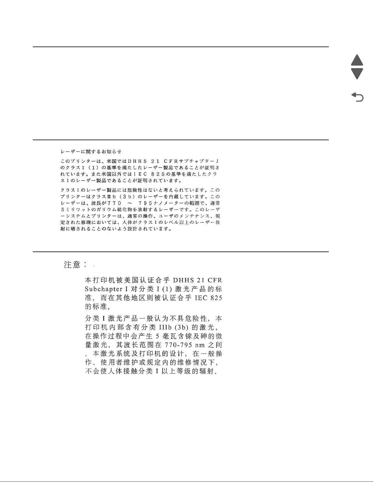
4062-XXX
Avís sobre el Làser
Segons ha estat cert ificat als Estats Units, aquesta impressor a compleix els requi sits de DHHS 21 CFR, apartat
J, pels productes làser de classe I (1), i segons ha estat cer tificat en alt res llocs, és un producte làser de classe
I que compleix els requisits d’IEC 60825-1.
Els productes l àser de classe I no es consideren perillosos. Aquesta impressora con té un làser de classe IIIb
(3b) d’arseniür de gal.li, nominalment de 5 mil.liwats, i funciona a la regió de longi tud d’ ona de 770-795
nanòmetres. El sistema làser i la impressora han sigut concebuts de manera que mai hi hagi exposició a la
radiació làser per sobre d’un nivell de classe I durant una operaci ó normal, durant les tasques de manteniment
d’usuari ni durant els serveis que satisfacin les condicions prescrites.
Previous
Next
Go Back
xviii Service Manual
Page 19
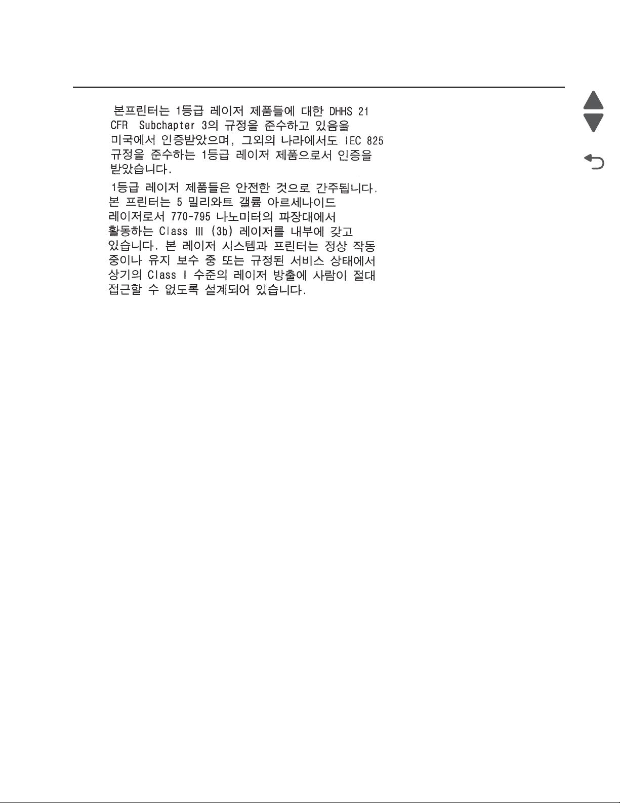
4062-XXX
Previous
Next
Go Back
Notices and safety information xix
Page 20

4062-XXX
Previous
Next
Go Back
xx Service Manual
Page 21
Lithium warn ing
4062-XXX
Previous
CAUTION
This product conta ins a lithium battery. THERE IS A RISK OF EXPLOSI ON IF THE BATTERY
IS REPLACED BY AN INCORRECT TYPE. Discard used batteries accordi ng to t he batt ery
manufacturer’ s instructions and local regulati ons.
Safety information
• The safety of this product is based on testing and approvals of the original design and speci fi c
components. The man ufacturer is not res ponsible for safety in the event of use of unauthorized
replacement parts.
• The maintenance inf ormation for this product has been prepared for use by a professional ser vice person
and is not intended to be used by others.
• There may be an increased risk of electric shock and personal injury during disassembly and servicing of
this product. Professional service personnel should understand this and take necessary precautions.
• CAUTION: When you see this symbol, there i s a danger from hazardous volta ge i n the area of the
product where you a re work ing. Unp lug th e product be fore y ou begin, or us e cau tion i f th e product
must receive power in order to perform the task.
Consignes de sécurité
• La sécurité de ce pro duit repose sur des tests et des
agréations por tant sur sa conception d' origine et sur des composants particuliers. Le fabricant n'assume
aucune respon sabilité concernant la sécurité en cas d'ut ilisation de piè ces de rechange non agréées.
• Les consignes d'entretien et de réparation de ce produit s'adressent unique me nt à un personnel de
maintenance qualifié.
• Le démontage et l'entretien de ce produit pouvant présenter certains risques électriques, le personnel
d'entretien qualifié devra prendre toutes les précautions nécessaires.
• ATTENTION : Ce symbole indique la présence d'une tension dangereuse dans la partie du
produit sur laquelle vous travaillez. Débranchez le produit avant de commencer ou fai tes preuve
de vigilance si l' exécution de la tâche exi ge que le produit reste sous tension.
Next
Go Back
Norme di sicurezza
• La sicurezza del prodotto si basa sui test e sull'approvazione del progetto originale e dei componenti
specifici. Il produttore non è resp onsabile per la sicur ezza in caso di sostituzione non autorizzata delle
parti.
• Le informazion i riguardanti la manutenzione di questo prodotto sono indirizzate soltanto al pers onale di
assistenza autorizzato.
• Durante lo smontaggio e la manutenzione di questo prodotto,
il rischio di subire scosse elettriche e danni alla persona è più elevato. Il personale di assistenza
autorizzat o deve, quindi, adott are le precauzioni necessarie.
• ATTENZIONE: Questo simbolo indi ca la presenza di tensione pericolosa nell' area del prodotto.
Scollegare il pr odotto prima di iniziare o usare cautela se il prodotto deve essere alimentato per
eseguire l'intervento.
Safety in fo rmation xxi
Page 22
4062-XXX
Sicherheitshinweise
• Die Sicherheit di eses Produkts basiert auf Tests und Zulassungen des ursprünglichen Mode ll s und
bestimmter Baut eil e. Bei Verwendung nicht genehmigter Ersatzteile wird vom Hersteller keine
Verantwortung oder Haftung für die Sicherheit übernommen.
• Die Wartungsinformationen für dieses Produkt sind ausschl ießlich für die Verwendung durch einen
Wartungsfachmann bestimmt.
• Während des Auseinandernehmens und der Wartung des Geräts besteht ein zus ätzliches Risiko eines
elektrischen Schlags und körperlicher Verletzung. Das zuständige Fachpersonal sollte entsprechende
Vorsichtsmaßnahmen treffen.
• ACHTUNG: Dieses Symbol weist auf eine gefährliche elektrische Spannung hin, die i n diesem
Bereich des Produkts auf tret en kann. Zieh en Sie vor den Arbeit en am Gerät den Netzsteck er des
Geräts, bzw. arbeiten Sie mit große r Vor sicht, wenn das Produkt für die Ausführung der Arbeiten
an den Strom angeschlossen sein muß.
Pautas de Seguridad
• La seguridad de este producto se basa en pruebas y aprobaciones del diseño original y componentes
específico s. El fabri cante no es responsabl e de la seguridad en caso de uso de piezas de repuesto no
autorizadas.
• La información sobre el mantenimiento de este producto está dirigida exclusivamente al personal
cualificado de mantenimiento.
• Existe mayor riesgo de de scarga e léc trica y de dañ os pe rsonal es du rante e l desmont aj e y la r eparaci ón de
la máquina. El personal cualificado debe ser consciente de este peligro y tomar las precauciones
necesarias.
• PRECAUCIÓN: este símbolo indica que el voltaje de la parte del equipo con la que está
trabajando es peligroso. Antes de empez ar, desenchufe el equipo otenga cuidado si, para
trabajar con él, debe conectarlo.
Previous
Next
Go Back
Inform a çõ es de Segurança
• A segurança deste produto baseia-se em testes e aprovações do modelo ori ginal e de componentes
específico s. O fabr icante não é responsá vel pela segunrança, no caso de uso de peças de substit uição
não autorizadas.
• As informações de segurança relativas a este produto destinam-se a profissionais destes serviços e não
devem ser utilizadas por outras pessoas.
• Risco de choques eléctricos e ferimentos graves durante a desmontagem e manutenção deste produto.
Os profissionais destes serviços devem estar avisados deste facto e tomar os cuidados necessários.
• CUIDADO: Quando vir este símbolo, existe a possível presença de um a potencial tensão
perigosa na zona do produto em que está a trabalhar . Ant es de com eçar, desligue o produt o da
tomada eléctr ica ou seja cu ida doso caso o pr oduto t enha de estar liga do à c orrent e eléc tric a para
realizar a taref a necessária.
xxii Service Manual
Page 23
Informació de Seguretat
• La seguretat d'aquest producte es basa en l' avaluació i aprovació del disseny original i els components
específics .
El fabricant no es fa responsable de les qüestions de
seguretat si s'u ti litzen peces de recanvi no autoritzades.
• La informació pel ma nteniment d’aquest producte està orient ada exclusivament a professionals i no està
destinada
a ningú que no ho sigui.
• El risc de xoc elèctric i de danys personals pot augmentar durant el procés de desmuntatge i de servei
d’aquest producte. El personal professional ha d’estar-ne assabentat i prendre
les mesures con venients.
• PRECAUCIÓ: aquest símbol indica que el voltatge de la part de l'equip amb la qual esteu
treballan t és perill ós. Abans de començ ar, desendol leu l' equip oextremeu les precaucion s si, per
treballar am b l'equip, l'heu de connect ar.
4062-XXX
Previous
Next
Go Back
Safet y inform a tion xxiii
Page 24
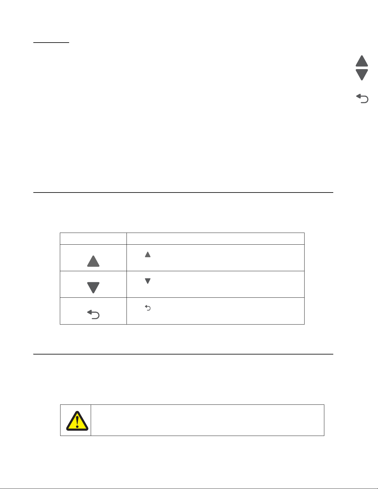
4062-XXX
Preface
This manual contains maintenance procedures for service personnel. It is divided into the following chapters:
1. General infor m a ti o n contains a general description of the printer and the maintenance approach used to
repair it. Speci al tools and test equip me nt, as well as general environmental and safety instructions, are
discussed.
2. Diagnostic information contains an error indicator table, sym ptom tables, and service checks used to
isolate failing field replaceable units (FRUs).
3. Diagnostic aids con tai ns tests and checks used to locate or repeat symp toms of printer probl ems .
4. Repair infor ma t io n provides instructions for making printer adjustments and removing and i nstalling
FRUs.
5. Connector locations uses il lustrations to identify the connector locations and test poi nts on the printer.
6. Preventive maintenance contains the lubrication specif ications and recomme ndations to prevent
problems.
7. Parts catalog cont ains illustrations and part numbers for individual FRUs.
Appendix A contains service tips and inf ormation.
Appendix B contains representative print samples .
Navigation buttons
This manual contai ns navigation buttons in the right margin of eac h page, making it easier and qui cker to
navigate.
Previous
Next
Go Back
Button Description
Previous
Next
Go Back
Conventions
Note: A note provides additional information.
Warning: A warning identi fi es something that might damage the product hardware or software.
There are several types of caution statements:
Click to move the document view backward by one page.
Click to move the document view for ward by one page.
Click to return to the last page viewed.
CAUTION
xxiv Service Manual
A caution identifies something that might cause a servicer harm.
Page 25
4062-XXX
CAUTION
This type of caution i ndicates there is a danger from hazardous voltage in t he area of the
product where you are working. Unplug the product befor e you begin, or use caution i f th e
product must recei ve power in order to perform the task.
CAUTION
This type of caution i ndicates a hot surface.
CAUTION
This type of caution i ndicates a tipping hazar d.
Previous
Next
Go Back
Conventions xxv
Page 26

4062-XXX
Previous
Next
Go Back
xxvi Service Manual
Page 27
4062-XXX
1. General information
The Lexmark™ laser pri nters are letter-quality page print ers designed to attach to per sonal computers and t o
most computer networks.
The Lexmark laser pri nters are availabl e in the following models:
Machine type Model Configuration
4062-01A T650n Network
4062-21A T652n Network
4062-23A T652dn Network
4062-41A T654n Network
4062-43A T654dn Network
4062-630 T656dne Network
Maintenance approach
The diagnostic information in this manual leads you to the correct field replaceable unit (FRU) or part. Use the
service erro r codes, user status messages, user error mes sages, service checks, and diagnostic aids to
determine the pr int er problem and repair the failure. After you co mp lete the repair, perform tests as needed to
verify the repair. See “Start” on page 2-1.
Previous
Next
Go Back
General information 1-1
Page 28

4062-XXX
Options
Available internal options
Previous
• Memory cards
– Pr i nter memory
– Flash memory
– Fonts
• Firmware cards
– Bar Code and Forms
– IPDS and SCS/TNe
– PrintCryption
– PRESCRIBE
• Printer hard disk
• Lexmark™ Internal Solutions Ports (ISP)
– RS-232-C serial interface ISP
– Parallel 1284-B interface ISP
– MarkNet
TM
– MarkNet N8130 10/100 Thick Fiber ISP
– MarkNet N8120 10/100/1000 Thick Ethernet ISP
• MarkNet N8110 v.34 Fax Card
The following opti ons are available. Some options are not available in every country. Contact your point of
purchase for opt ions available in your country.
Media handling options
– 250- and 550-sh eet paper trays of A4, letter, A5, B5, Executive, folio, st atement, and legal siz e
– 250-sheet universally adjustable tray
– 250- and 550-sh eet paper drawers
– 2000-sheet high-capacity feeder
– Envelope feeder (Not for use with the T656dne)
– Duplex option—250-sheet (external)
– Duplex option—550-sheet (internal on duplex versions of T652 and T654)
– Output expander
– High-capa city output stacker
– StapleSmart™ Finisher
– 5-bin Mailbox
– Vertical Kiosk Presenter
– Horizontal Kiosk Presenter
– RFID UHF (only for T654)
Next
Go Back
TM
N8150 802.11 b/g/n Wireless ISP
1-2 Service Manual
Page 29
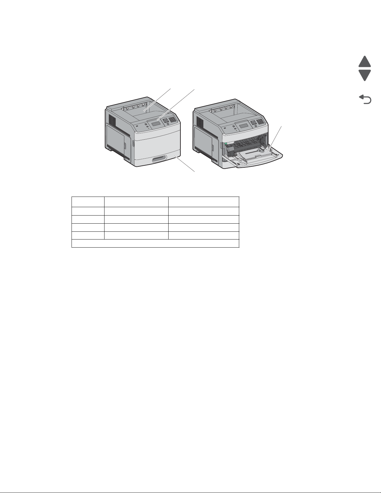
4062-XXX
Printer configurations
Basic model
The following illustration shows the basic printer model.
Feature Paper Capacity
1 Standard exit bin 250- or 550-sheet
2 Printer control panel NA
3 Multipurpose feeder 100 sheets
4 Standard tra y (Tray 1) 250- or 550-sheets
1
Based on 75 g/m2 (20 lb.) paper.
Previous
1
2
Next
Go Back
3
4
1
General information 1-3
Page 30
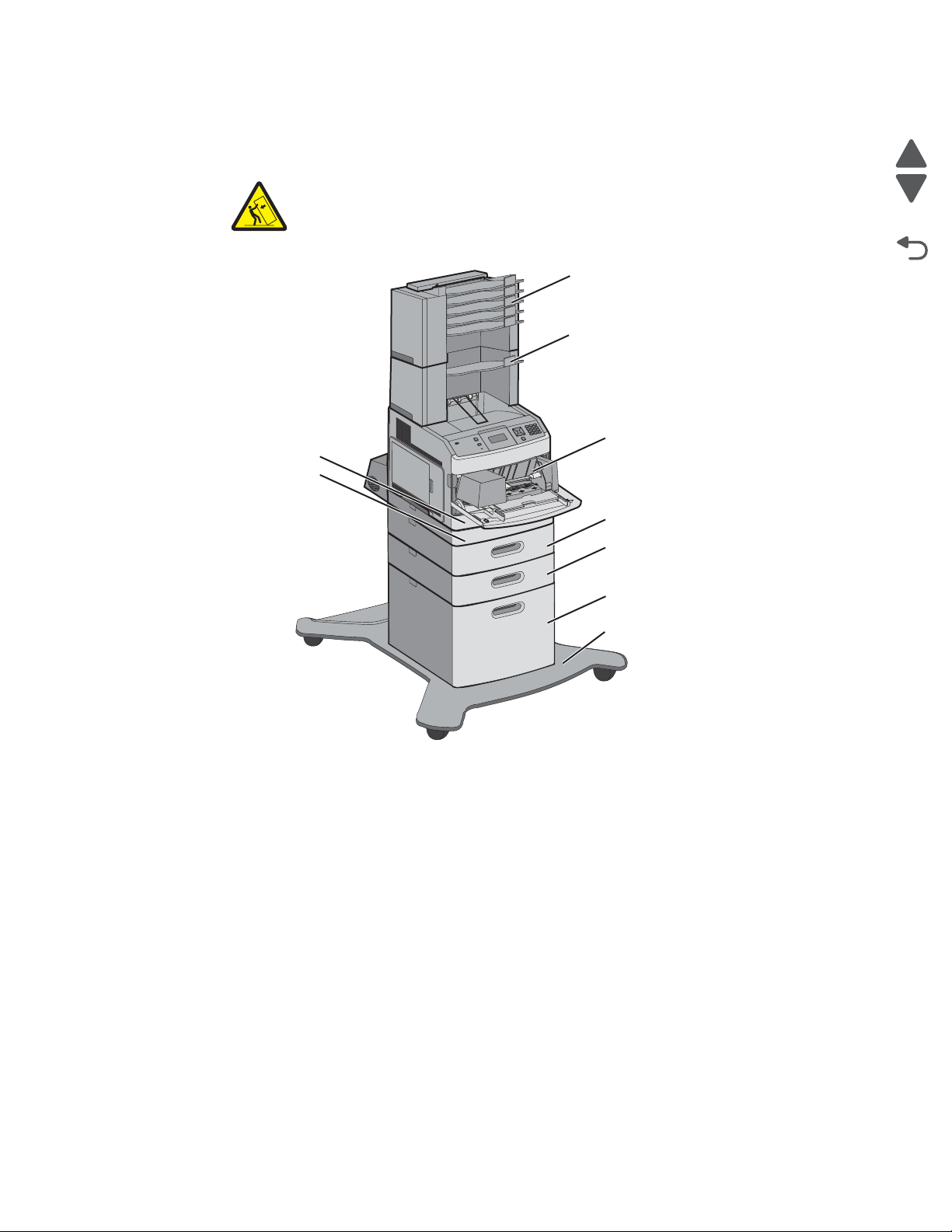
4062-XXX
Fully configured model
The following illustration shows the fully configured printer model.
CAUTION: —TIPPING HAZARD: Floor-mounted configurations require additional
furniture for stability. You must use either a printer stand or printer ba se if you are using
a 2000-sheet tray, a duplex unit, and an input option, or more than one input option.
For more in fo rmation, se e www.lexmark.com/publications/furniture_safety.
4
5
Previous
Next
1
Go Back
2
3
6
7
8
9
1-4 Service Manual
Page 31
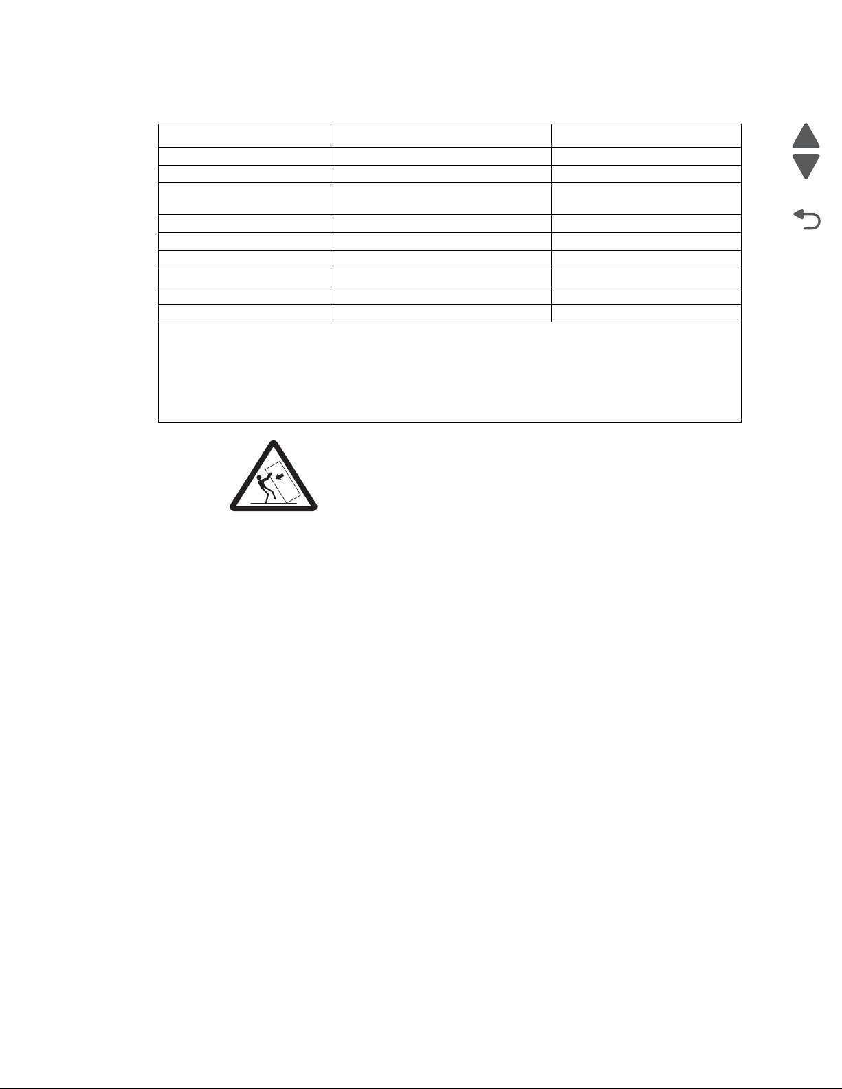
Feature/Opti on Paper Capacity
1 5-bin mailbox
2 Output expander
2
3
3 Envelope feeder (Not for use with
500 sheets
550 sheets
85 envelopes
1
the T656dne)
4 Standard tray (Tray 1) 250 or 550-sheets
5 Dup l ex unit
4
Not applicable
6 Optional tray (Tray 2) 250- or 550-sheet s
7 Optional tray (Tray 3) 250- or 550-sheet s
8 Optional 2000- sheet tray (Tray 4) 2000 sheets
9 Caster base Not applicable
1
Based on 75 g/m2 (20 lb.) paper.
2
Up to two 5-bin mailbox unit s are supported.
3
The printer supports up to three output expande r uni ts, or one output expander combine d wit h one 5-
bin mailbox, one high capacity output expander (not depicted), or one stapler unit (not depi cted).
4
Optional external duplex unit for the T650 model. All other models are available with or without
internal duplex unit.
CAUTION: Floor-mount ed co nfigur atio ns requi re fu rnitu re for stabi lit y. You must
use either a printer stand or printer base i f you are using a 2000-sheet drawer.
Certain othe r conf igurations also must have a printer stand or printer base. M ore
information is available at our Lexma rk Web site at www.lexmark.com/
multifunction printers.
4062-XXX
Previous
Next
Go Back
General information 1-5
Page 32
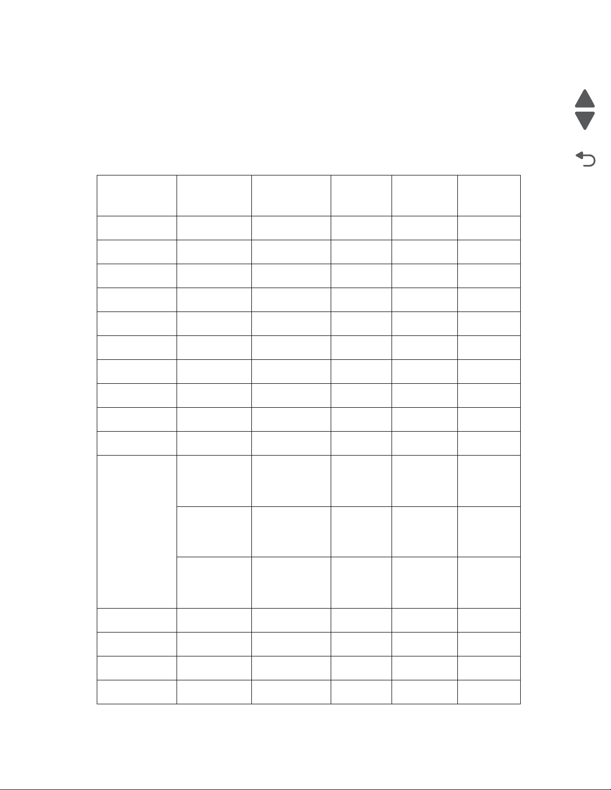
4062-XXX
Supported paper sizes, types, and weights
The following tabl es provide informati on on standard and optional paper sources and the types of paper they
support.
Note: For an unlisted paper size, select the closest larger listed size.
Paper sizes supported by the printer
250-or 550-sheet
Paper size Dimensions
A4 210 x 297 mm
(8.3 x 11.7 in.)
A5 148 x 210 mm
(5.8 x8.3in.)
1,2
A6
105 x 148 mm
(4.1 x 5.8 in.)
J15 B5 182 x 257 mm
(7.2 x 10.1 in.)
Letter 216 x 279 mm
(8.5 x 11 in.)
Legal 216 x 356 mm
(8.5 x14 in.)
Executive 184 x 267 mm
(7.3 x 10.5 in.)
1
Oficio
216 x340 mm
(8.5 x 13.4 in>)
1
Folio
216 x 330 mm
(8.5 x 13 in.)
Statement
1
140 x 216 mm
(5.5 x8.5 in.)
Universal
3,4
138 x 210 mm
(5.5 x8.3 in.) u p
to
216 x 356 mm
(8.5 x 14 in.)
70 x 127 mm
(2.8 x 5 in.) up
to
216 x 356 mm
(8.5 x 14 in.)
148 x 182 mm
(5.8 x 7.7 in.) up
to
216 x 356 mm
(8.5 x 14 in.)
7 3/4 Envelopes
(Monarch)
98 x 191 mm
(3.9 x 7.5 in.)
9 Envelope 98 x 225 mm
(3.9 x 8.9 in.)
10 Envelope 105 x 241 mm
(4.1 x 9.5 in.)
DL Envelope 110 x 220 mm
(4.3 x 8.7 in)
trays (standard
or optional
Previous
Next
Go Back
Optional
2000-sheet
tray
Multipurpose
feeder
Duplex unit
xxxx
xxx
x
xxx
xxxx
xxxx
xxx
xxx
xxx
xx
xx
x
xxx
x
x
x
x
1-6 Service Manual
Page 33
4062-XXX
Optional
2000-sheet
tray
Multipurpose
feeder
x
Duplex unit
Paper size Dimensions
Other Envelope 98 x 162 mm
250-or 550-sheet
trays (standard
or optional
(3.9 x 6.4 in.) to
176 x 250 mm
(6.9 x 9.8 in.)
1
This size appears in the Paper Size m enu only when the paper source does not support size sensing or
when size sensing is turned off.
2
Only the standard exit bin supports this size.
3
This size setting formats the page for 216 x 356 mm (8.5 x 14 in.) unless the siz e is specified by the
software applicat ion.
4
To support duplexing, the Universal wid th must be between 148 mm (5.8 in) and 216 mm (8.5 in) ;
Universal length must be between 182 mm (7.2 in) and 356 mm (14 in).
Paper types and weights supported by the printer
250-or 550-sheet
Paper type
trays (standard or
optional
Paper
xxxx
•Plain
• Bond
• Colored
•Custom
• Letterhead
• Light
• Heavy
•Preprinted
• Rough/Cotton
•Recycled
Card stock xxxx
Envelopes x
1
Labels
xxxx
Transparencies xxxx
1
Printing labe ls req ui res a spe cial label fuser cl eaner whi ch prev ents dup lex ing. The label fuse r c leaner is
included with the speci al cartridge requ ired for label applicat ions.
Optional 2000sheet tray
Multipurpose
feeder
Duplex unit
Previous
Next
Go Back
Paper types and weights supported by the output bins
Use this table to det ermine the possible output destinations of print jobs which use supp ort ed paper types and
weights. The paper capacity of each output bi n is listed in parentheses. Paper capacity est imations are
calculat ed based on 75 g/m
2
(20 lb) paper.
General information 1-7
Page 34
4062-XXX
The finisher supports 60-176 g/m2 (16-47 lb) paper weights.
Optional hardware
Output
Paper type
Standard exit bin
(350 or 550 sheets)
Expander (550
sheets) or High
Capacity
Output stacker
5-Bin Mailbox
(500 sheets)
1
StapleS m a r t II
Finisher
(500 sheets)
(1850 sheets)
Paper
xxxx
•Plain
• Bond
• Colored
•Custom
• Letterhead
•Light
• Heavy
• Preprinted
• Rough/Cotton
• Recycled
Card stock xx
Envelopes
1
Labels
xx
Transparencies xx
1
Supports 60-90 g/m2 (16-24 lb) paper weights.
2
Maximum of 50 sheets of 75 g/m2 (20 l b) paper per stapled packet. Results may vary with h eavier
paper.
Previous
Next
2
Go Back
Tools required
Flat-blade screwdrivers, various sizes
#1 Phillips screwdriver, magnetic
#2 Phillips screwdriver, magnetic
#2 Phillips screwdriver, magnetic short-blade
7/32 inch (5.5 mm) open-end wrench
7.0 mm nut driver
Needle nose pliers
Diagonal side cutters
Spring hook
Analog or digital multimeter
Flash light (optional)
1-8 Service Manual
Page 35

Acronyms
BLDC Brushless DC motor
CRU Customer Replaceable Unit
CSU Customer setup
DIMM Dual Inline Memory Module
DRAM Dynamic Random Access Memory
DVM Digital multimeter
EDO Enhanced Data Out
EEPROM Electrically Erasable Programable Read-Only Memory
EP Electrophotographic process
EPROM Erasable Programmable Read-Only Memory
ESD Electrostatic Discharge
FRU Field Replaceable Unit
GB Gigabyte
HCIT High-capacity Input Tray
HVPS High Voltage Power Supply
ITC Internal Tray Card
LASER Light Amplification by Stimulated Emission of Radiation
LCD Liquid Crystal Display
LED Light-Emitting Diode
LVPS Low Voltage Power Supply
MPF Multipurpose feeder
MROM Masked Read Only Memory
MS Microswitch
NVRAM Nonvolatile Random Access Memory
OEM Original Equipment Manufacturer
OPT Optical Sensor
PC Photoconductor
pel Picture element
POR Power-On Reset
POST Power-On Self Test
PP Parts Packet
PWM Pulse Width Modulation
RFID Radio Frequency Identification
RIP Raster Imaging Processor
ROM Read Only Me mor y
SDRAM Sync hronou s Dynamic Random Access Memory
SIMM Single Inline Memory Module
SRAM Static Random Access Memory
UAT Universally Ad jus table Tray)
UPR Used Parts Return
V ac Volts alternating curren t
V dc Volts direct current
VOM Volt Ohmmeter
4062-XXX
Previous
Next
Go Back
General information 1-9
Page 36

4062-XXX
Previous
Next
Go Back
1-10 Service Manual
Page 37
4062
2. Diagnostic information
Start
CAUTION:
Unplug the power cord from the electrical outlet before you connect or disconnect any cable or
electronic board or assembly.
If the printer is kept on, never t ouch the conduc tive part s if not specif ically requir ed. The power
switch and inlet of the l ow volt age power s upply ca rd ( LVPS card) assembly i s li ve even whi le
the power supply is cut off. Never touch the live parts.
Be careful to avoid burns by safely handling hot parts.
Previous
Next
Go Back
CAUTION:
CAUTION:
CAUTION
The printer weight is gre ater t han 18k g (40 lbs) and r equire s two or more tr ained per sonn el to
lift it safely. Use the hand holds on the side of the printer. Make sure your fi ngers are not
under the printer when you lift or set the printer down.
WARNING: When operating the dr ivin g units us ing the diagnost i cs or othe r tool s, be sur e to keep th em cover ed
unless otherwi se specified.
WARNING: When operatin g the driving units using the di agnostics or other tools, never touch the driv ing units.
When operating the dr iving units using diagnostics or other too ls, be sure to follow the procedures in this
manual.
WARNING: Servicers shoul d wear a wri st band or the like to remove static el ectri cit y from the ir body, groundi ng
their body while work ing. Go to “Handling ESD-sensitive parts” on page 4-1.
Note: There may be printer error messages that are not contained in this service manual. Call your next level
support for ass istance.
Diagnostic information 2-1
Page 38

4062
Confirm the installation status
Be sure to check the following items before st arting the troubleshooting procedures.
Previous
• With the power co rd un plugged f rom the wal l out let, check th at the co rd is f re e from bre akage, sh ort-c ircui t,
disconnected wire, or incorrect con nection in the power cord.
• The printer is properly grounded. Check t he power cord ground terminal .
• The printer is no t inst alle d at a plac e subjec ted to extr eme temp erature, e xtrem e humidi ty or r apid chan ges
in temperatur e.
• The printer is not i nstalled close to wate r service, humidif ier , heat generating unit , fire, in a very dusty
place, or a place exposed to air flow from the air conditioning system.
• The printer is not installed in a place where volatile gas or inflammable gas is generated.
• The printer is not i nstalled in direct sun.
• The printer is inst alled on a level and stabl e surface.
• Media meets specifications and is installed properly.
• Customer maintenance parts have been replac ed at the specified intervals.
• Check all attached options for proper at tachment and electric al connection.
• Refer to th e User’s Guide for proper installation.
Power-on Reset sequence
The following is an example of the events that oc cur dur ing the POR sequence:
1. Turn the machine on.
2. The Lexmark splash scr een appears with a progress bar in the center until the code is loaded.
3. The fuser cooling fan t urns on.
4. The fuser unit assem bly lamps turn on.
5. The system card assembly cooling fan turns on.
6. Operator panel LED become s sol id.
7. The transport motor turns on.
Next
Go Back
Entering Diagnostics mode
1. Turn the printer off.
2. Press and hold and .
3. Turn the printer on.
4. Release the buttons after 10 seconds.
2-2 Service Manual
Page 39

User atten da nce me ss ag es
Error
code or
message
Error contents Description/Action Possible repair actions
4062
Previous
Next
System
Timeout
System Timeout The system detects a firmware
component that is no longer
responding.
30.XX Invalid Refill Change
Cartridge
Message is cleared when a
new print cartridge is installed.
31.XX Defective Cartridge Error code 31 displays when
the top front cover is closed
and a defective print car tridge
is detected. It may take the
printer 10-20 seconds to
determine if the pri nt car tridge
is defective.
32.XX Cartridge part number
X unsupported by
device
Error 32 displays when the top
cover is closed and an
unsupported prin t car tridge is
detected. It may take the
printer 10-20 seconds to
determine if the pri nt car tridge
is supported.
34 Short Paper The printer determines the
paper length is too short to
print the formatted data. This
occurs when the printer does
not know the actual paper size
loaded in the tray. For autosize sensing trays, this error
occurs if the paper stop is in
the incorrect position. Make
sure the Paper Size setting is
correct for the si ze paper tha t is
being used.
Turn the power off; wait a few
seconds, and then turn the
power back on.
Install the proper print
cartridge.
1. Install the proper print
cartridge.
2. Ensure the pr int cartridge ID
connector as sembl y is pr operl y
connected.
3. Replace the print cartridge
ID connector assembly if
problem remains. Go to “Print
cartridge ID connec tor
assembly removal” on
page 4-58.
Install the proper print
cartridge.
1. Ensure the media tray
guides are proper ly set for the
media being used.
2. Ensure the Switch media
size is properly connected.
3. Replace the switch media
size if problem remains.
Go to “Switch (media size)
assembly removal” on
page 4-73.
4. Replace the media tray
assembly if prob lem remains.
Go Back
Diagnostic information 2-3
Page 40
4062
Error
code or
Error contents Description/Action Possible repair actions
message
35 Res Save Off
Deficient Memory
This IR is displayed when the
printe r la c ks sufficient me mo ry
to enable Resource Save. This
message usually indicates the
user has allocated too much
memory for one or more of the
printe r's link buff e rs ; how e v e r,
modification of ot her printer
settings which affe ct the
amount of available me mory
may also create this condition.
If the user desires to enable
Resource Save after this
message has been post ed, i t is
recommended the user either
install addit ional memory or set
each link buffer back to the
Auto value.
Once all link buffer s are
returned to Auto, the user
should exit the menus to
activate the link buffer
changes. Once the printer
returns to the Ready state, the
user may then enable
Resource Save an d t hen fina lly
go back and modify the link
buffers again. The user should
note the reduction of available
memory to the link buffers
when Resource Save has be en
enabled as opposed to the
memory available when
Resource Save is disabled.
This message displays when
the printer lacks sufficient
memory to enable Resourc e
Save. This message usually
indicates t he user has
allocated too m uch memory for
one or more of the printer link
buffers; however, modificatio n
of other printer sett ings which
affect the amount of available
memory may also create this
condition. If restoration of
Resource Save is required
after this mess age is received,
the customer shoul d install
additional me mory or set each
link buffer to Aut o. Once al l link
buffers are retur ned to Auto,
you should exit the me nu to
activate th e li nk buffer
changes. Once the printer
returns to the Ready stat e, you
can enable Res ource Sa ve and
go back and modify the link
buffers again. Note the
reduction of avail able memory
to the link buffers when
Resource Save has been
enabled, and compare it to the
memory availabl e when
Resource Save is disabled.
• Press to disable
Resource Save and
continue printing.
To enable Resource Save
after you get this message:
- Make sure the link
buffer s ar e se t to Au to ,
then exit the menus to
activate th e li nk buffer
changes.
- When Ready is
displayed, enable
Resource Save.
• Install additional memory.
Previous
Next
Go Back
37 Insufficient Collation
2-4 Service Manual
Area
This message displays when
the prin ter memo ry is
insufficient to perf orm the Fl ash
Memory Defragment operation.
Note: This message is post ed
prior to the actual start of the
defragment operat ion. The
printer code determines if
enough printer memory is
available to complete the
defragment operat ion. The
user should not be concerned
with losing resources stored in
the flash op tion.
The following actions may be
taken:
• Press to clear the
message. To perform the
defragment operation:
- Delete fon ts, macros,
and other data in RAM.
- Install additional printer
memory.
• Press until Busy/
Waiting appears . The
following actions are
available:
-Cancel Job
- Reset Printer
- Reset Active Bin
Page 41
4062
Error
code or
Error contents Description/Action Possible repair actions
message
37 Insufficient Memory This message displ ays when
the pri n ter memory u s ed to
restore the Print and Hold jobs
from the disk and found that
some or all of the jobs could
not be restor ed. The print er ran
out of memory while at tempting
to restore the jobs.
38 Memory Full This message displays when
the printer is processing an
incoming job and there is
insufficient memory available
to continue proces sing the job.
The following actions may be
taken:
• Press to clear the
message. Some of the Print
and Hold jobs on the disk
will not be restored. They
remain on the disk, but
cannot be accessed.
• Press until Busy/
Waiting appears . The
following functions may be
available:
-Cancel Job
- Reset Printer
Reset Active Bin
The following actions may be
taken:
• Press to clear the
message. Perform the
defragment operation:
- Perform the def ragment
operation
- Delete fon ts, macros,
and other data in RAM
- Install additional
memory
Previous
Next
Go Back
39 Complex Page This message displays when
the page is too complex to
print. The following actions
may be taken:
• Press to display Busy/
Waiting. The following
functions may be available:
-Cancel Job
- Reset Printer
Reset Active Bin
The following actions may be
taken:
• Press to clear the
message and continue the
job. Some data loss may
occur. Simplify the print job
and reprint, if necessary.
• Press until Busy/
Waiting appears . The
following selections are
possible:
-Cancel Job
- Reset Printer
Reset Active Bin
Diagnostic information 2-5
Page 42
4062
Error
code or
Error contents Description/Action Possible repair actions
message
44.01 RFID Error Bad tag error: a tag has failed
to program, or the “Retry
Count” has been exceeded.
Note: This error is not a data
parsing error, but indi cates ba d
RFID media. It is posted only if
the “Stop on Error” menu
settin g is set to “O N ” .
1.Retest using new RFID
media.
2.Check the RFID firmware
card, RFID interface card,
RFID cable, and RFID
option for correct
installation. Go to
“Installing / Removing
the RFID UHF option” on
page 4-149.
3.Replace the RFID UHF
option.
44.11 RFID Error Generic parse error 1.These error codes most
likely indicate a problem
44.12 RFID Error Subcommand appears
truncated
44.13 RFID Error Subcommand appears lon ger
than expec te d
44.14 RFID Error Subcommand field value was
invalid
with the customer’s
datastream, and not the
RFID Option itself. Ensure
there is nothing wron g wit h
the customer’s datastream.
2.Check the RFID firmware
card, RFID interface card,
RFID cable, and RFID
44.15 RFID Error Invalid subcommand fo rmat
(invalid magic byte)
44.16 RFID Error Subcommand format valid but
not supported
44.17 RFID Error Illegal chars in subcommand
for specified format
option for correct
installation. Go to
“Installing / Removing
the RFID UHF option” on
page 4-149
3.Replace the RFID UHF
option.
Previous
Next
Go Back
44.18 RFID Error Invalid op code
44.19 RFID Error Valid but unsupported op code
44.20 RFID Error Invalid protocol
44.21 RFID Error Valid but unsupported protocol
44.22 RFID Error Unsupported optio n supplied
44.23 RFID Error Invalid ID length
44.24 RFID Error Invalid ID bit pattern
44.25 RFID Error Too many tags on page (too
2-6 Service Manual
for operation
many means more than one)
Page 43
4062
Error
code or
Error contents Description/Action Possible repair actions
message
44.26 RFID Error Based on tag location
parameters: tag is not
compatible with printer
44.27 RFID Error Unsupported SA Code
44.28 RFID Error Invalid Power setting
44.29 RFID Error Unsupported Featur e
44.31 RFID Error Generic run-time reader error
44.32 RFID Error Reader response timeout
44.33 RFID Error Garbled o r short re sponse from
reader
44.34 RFID Error Read/Verify operation failed
(tag data from reader !=
expected value)
1.These error codes most
likely indicate a problem
with the customer’s
datastream, and not the
RFID Option itself. Ensure
there is nothing wron g wit h
the customer’s datastream.
2.Check the RFID firmware
card, R F ID inter face card,
RFID cable, and RFID
option for correct
installation. Go to
“Installing / Removing
the RFID UHF option” on
page 4-149.
3.Replace the RFID UHF
option.
1.Retest using new RFID
media
2.Check the RFID firmware
card, R F ID inter face card,
RFID cable, and RFID
option for correct
installation. Go to
“Installing / Removing
the RFID UHF option” on
page 4-149.
3.Replace the RFID UHF
option.
Previous
Next
Go Back
44.35 RFID Error Invalid RFID region 1.Check the RFID firmware
card, R F ID inter face card,
RFID cable, and RFID
option for correct
installation. Go to
“Installing / Removing
the RFID UHF option” on
page 4-149.
2.Replace the RFID UHF
option.
Diagnostic information 2-7
Page 44
4062
Error
code or
Error contents Description/Action Possible repair actions
message
44.36 RFID Error Invalid X/Y Position 1. This error code most likely
indicates a problem with
the customer’ s datastream ,
and not the RFID Option
itself. Ensure there is
nothing wrong with the
customer’s datastream.
2.Check the RFID firmware
card, RFID interface card,
RFID cable, and RFID
option for correct
installation. Go to
“Installing / Removing
the RFID UHF option” on
page 4-149.
3.Replace the RFID UHF
option.
42.XY Cartridge Region
Mismatch
This IR is displayed when the
printer detect s that the inst alled
cartridge has a region t hat
Install a new toner car tridge
that matches the correct
regional spec ification.
differs from the below options.
To clear this IR, the printer
cartridge must be r eplaced with
one that has a proper region.
X and Y can have the followi ng
values:
0 : Worldwide region or
Undefined region
1 : America
2 : EMEA
3 : Asia
4 : Latin America
9 : Invalid region
Previous
Next
Go Back
50 PPDS Font Error This message displays when
51 Defective Flash This message display s when
2-8 Service Manual
the PPDS interpreter has
encountered a font error.
Note: This error may only
occur when the printer is
formatting PPDS print data.
the printer detect s a defective
flash. This error may occur at
power on, or during flash
format and write operations.
The following actions may be
taken:
• Press to clear the
message and continue
processing the job.
• Press until Busy/
Waiting appears . The
following are available:
-Cancel Job
- Reset Printer
- Reset Active Bin
Press to clear the
message. The flash i s ma rked
as bad and normal operation
continues. Flash operations
are not allowed unti l the
problem is resolved.
Page 45
4062
Error
code or
Error contents Description/Action Possible repair actions
message
52 Flash Full This message displays when
the printer detect s an
unformatted flash at power on.
54 Serial Option [x] Error This IR is displayed when a
serial error (frami n g , p ar it y o r
overrun) has been detected on
the specified optional serial
port. This usually indicates that
the serial port has not been set
up correctly.
Once a host interf ace err or has
been displayed for the first
time, reporting of further host
interface errors fo r th e
associated port is suppressed
until the interface parameters
are changed for the
associated, or the machine is
powered off.
54 Std Network Software
Error
This error displays when a
network port is detected, but
the printer cannot establish
communications with it.
Press to clear the
message. The flash i s ma rked
as bad and normal operation
continues. Flash operations
are not allowed unti l the flash is
formatted.
Go to network service check.
See “ Network se rvice ch eck”
on page 2-169.
The following actions may be
taken:
•Press
to clear the
message and continue
printing.
The job may not print
correctly.
• Program new firmware for
the network interf ace.
Reset the printer.
Previous
Next
Go Back
54 Network [x] Software
Error
55 Unsupported Option
in Slot [x]
56 P ara lle l P o rt [x ]
Disabled
This error displays when a
network port is detected, but
the printer cannot establish
communications w it h it.
An unsupported option is
installed in the specified
soluti o ns port. Power of f th e
printer and remove the
unsupported opti on in the
specified slot.
This error displays when data
is sent to the printer across an
optional parall el port, but the
port has been disable d. Once
this message displ a ys,
reporting of further errors is
suppressed unti l the menus are
entered, or the printer is reset.
The following actions may be
taken:
• Press to clear the
message and continue
printing.
The job may not print
correctly.
• Program new firmware for
the network interf ace.
• Reset the printer.
Remove unsupported option.
Go to network service check.
See “ Network se rvice ch eck”
on page 2-169.
Diagnostic information 2-9
Page 46
4062
Error
code or
Error contents Description/Action Possible repair actions
message
56 Serial Port [x]
Disabled
This error displays when data
is sent to the printer across an
serial port, but the port has
been disabled. Once th is
message displays, reporting of
further errors i s suppressed
until the menus are entered, or
the printer is reset.
56 Standard USB Port
Disabled
Displayed when status is
requested over the USB port,
but the port has been disable d.
Once the error has been
displayed for the fi rst time,
reporting of further errors is
suppressed unti l the menus are
entered or the printer is reset.
56 USB Port [x] Disabled Displayed when status is
requested over the USB port,
but the port has been disable d.
Once the error has been
displayed for the fi rst time,
reporting of further errors is
suppressed unti l the menus are
entered or the printer is reset.
Go to network service check.
See “ Network se rvice ch eck”
on page 2-169.
The following actions may be
taken:
• Press to clear the
message. The printer
discards any data received
on the USB port.
• Press until Busy/
Waiting appears . The
following are available:
- Reset Printer
Reset Active Bin
The following actions may be
taken:
• Press to clear the
message. The printer
discards any data received
on the USB port.
• Press until Busy/
Waiting appears . The
following are available:
- Reset Printer
Reset Active Bin
Previous
Next
Go Back
58 Invalid Tray
58 Too Many Bins
2-10 Service Manual
Configuration
Attached
Either no input trays or there
are optional trays above the
RFID option.
This error code displays when
too many bins are attached to
the printer.
1.Ensure the RFID option is
in first p osition under pri nter
and that there is at least
one input tray bene ath the
RFID option.
2.Check the RFID firmware
card, RFID interface card,
RFID cable, and RFID
option for correct
installation. Go to
“Installing / Removing
the RFID UHF option” on
page 4-149.
3.Replace the RFID UHF
option.
1.Turn off and unplug the
printer.
2.Remove the excess bins.
3.Plug in the pri nter, and turn
it on.
Page 47
4062
Error
code or
Error contents Description/Action Possible repair actions
message
58 Too Many Disks
Installed
This error code displays when
too many disks are attached to
the printer.
58 Too Many Flash
Options
This error code displays when
too many user flash memory
options or too many optional
firmware cards have been
installed.
User can power off a nd remove
extra flash options .
58 Too Many Trays
Attached
This error code displays when
too many input trays are
attached to the printer.
Note: With the RFID option
attached, the maximum
number of trays is three.
Without the RFID option
attached, the maximum
number is four.
59 Incompatible Duplex An incompatible duplex opti on
is installed.
Remove the incompatible
duplex option and pre ss
to clear the message.
Note: If the user insta ll ed the
incompatible dev ice to satisfy a
Check Device Connections/
reattach message, the user
should reinstall an associated
compatible opt ion or hot unplug
the option.
1.Turn off and unplug the
printer.
2.Remove the excess disks.
3.Plug in the pri nter, and turn
it on.
1.Turn off and unplug the
printer.
2.Remove the excess flas h
memory.
3.Plug in the pri nter, and turn
it on.
1.Turn off and unplug the
printer.
2.Remove the excess tray s.
3.Plug in the pri nter, and turn
it on.
1.Turn off and unplug the
printer.
2.Remove the incompatible
external duplex unit
assembly.
3.Plug in the pri nter, and turn
it on.
Previous
Next
Go Back
59 Incompatible
Envelope Feeder
An incompatible envelope
feeder is installed.
Remove the incompatible
feeder and press to clear
the message.
Note: If the user insta ll ed the
incompatible dev ice to satisfy a
Check Device Connections/
reattach message, the user
should reinstall an associated
compatible opt ion or hot unplug
the option.
1.Turn off and unplug the
printer.
2.Remove the incompatible
envelope feeder.
3.Plug in the pri nter, and turn
it on.
Diagnostic information 2-11
Page 48
4062
Error
code or
Error contents Description/Action Possible repair actions
message
59 Incompatible Outp ut
Bin [x]
An incompatible output bin is
installed. For Output Bin x, x=1,
2, or 3.
Remove the incompatible
output bin and press to
clear the message.
Note: If the user insta ll ed the
incompatible dev ice to satisfy a
Check Device Connections/
reattach message, the user
should reinstall an associated
compatible opt ion or hot unplug
the option.
59 Incompatible Tra y [x] An incompatible tray i s
installed. For Tray x, x= 2, 3, 4,
or 5.
Remove the incompatible tray
and press to clear the
message.
Note: If the user insta ll ed the
incompatible dev ice to satisfy a
Check Device Connections/
reattach message, the user
should reinstall an associated
compatible opt ion or hot unplug
the option.
1.Turn off and unplug the
printer.
2.Remove the incompatible
output option.
3.Plug in the pri nter, and turn
it on.
1.Turn off and unplug the
printer.
2.Remove the incompatible
trays.
3.Plug in the pri nter, and turn
it on.
Previous
Next
Go Back
61 Defective Disk This error code displays when
the printer detect s a defective
disk. This error may occur at
power on or during disk format
and write operati ons. While t his
message displays.
62 Disk Full Thi s err or code displays when
there is not enough free space
on the disk to hold the
resources that hav e been
requested to be written to the
disk. This messa ge displays for
both resource and PostScript
Disk operators when th e disk is
full.
80 Routine Maintenance
Needed
The operator panel displays
this message at each 300K
page count interva l. It is
necessary to repl ace the fuser
assemb ly, tran sfer roller,
charge roll, and pi ck rolls at this
interval to mainta in t he print
quality and reliability of the
printer. The parts are avai lable
as a maintenance ki t. For mor e
information, go to “Scheduled
maintenance” on page 6-2.
press to clear the
message. The disk is mar ked
defective and norm al printer
operations con tinue. Disk
operations are not allowed with
a defective disk. The Format
Disk menu is not shown.
TBD
Scheduled maintenance
required.
Refer to chapter 6.
Go to “Preventive
maintenance” on page 6-1.
2-12 Service Manual
Page 49

4062
Error
code or
Error contents Description/Action Possible repair actions
message
88 Cartridge Low This IR is displayed when
cartridge low occurs and the
cartridge low alarm is
activated. If car tridge alarm is
not activated, this is not an
intervention condition.
88 Cartridge Nearly Low This IR is displayed when
cartridge low occurs and the
cartridge low alarm is
activated. If car tridge alarm is
not activated, this is not an
intervention condition.
88 Replace Cartridge Thi s IR is displayed when ton er
cartridge is exhausted/empty.
Previous
Replace the print car tridge.
Next
Go Back
Replace the print car tridge.
Replace the print car tridge.
Diagnostic information 2-13
Page 50

4062
Error co de ta ble 1
Error
code or
message
Error contents Description/Action Possible repair actions
Previous
Next
200.00 Sensor (input) area
jam
200.01 Sensor (input)
lingering jam
Source = MPF, duplex
or envelope feeder
200.02 Sensor (input)
lingering jam
200.04 Sensor (input) early
jam
The media is jammed in the
sensor (input) area.
The media reached the sensor
(input) but did not cle ar it wit hin
the specified time.
The media reached the sensor
(input) but did not cle ar it wit hin
the specified time.
The media reached the sensor
(input) sooner than the
specified time.
Wrong config ID cau ses engine
to assume 500 paper path on
250 model.
1. Fan the media and check for
obstructions.
2. Go to sensor (inpu t) service
check.
See “Sensor (input) service
check” on page 2-119.
1. Fan the media and check for
obstructions.
2. Go to sensor (inpu t)
lingering jam service check.
See “ Sensor ( input) linger ing
jam service check.” on
page 2-125.
1. Fan the media and ensure it
is properly installed.
2. Go to sensor (inpu t)
lingering jam service check.
See “ Sensor ( input) linger ing
jam service check.” on
page 2-125.
1. Fan the media and ensure it
is properly installed.
2. Go to sensor (inpu t) early
jam service check.
See “Sensor (input) earl y jam
service check” on
page 2-126.
Go Back
200.06 Sensor (input) early
200.07 Sensor (input) late
200.08 Sensor (input) early
2-14 Service Manual
jam
jam
Source = input option
tray
jam
The sensor (input) rebounded
once the trailing edge of the
media passed.
The media is late reaching t he
sensor (input) within the
specified time.
The media reaches the sensor
(input) sooner than the
specified time.
Go to sensor (input) service
check.
See “Sensor (input) service
check” on page 2-119.
Go to sensor (input) late jam
service check.
See “Senso r (i n p ut ) la te ja m
service check.” on
page 2-122.
1. Fan the media and ensure it
is properly installed.
2. Go to sensor (inpu t) early
jam service check.
See “Sensor (input) earl y jam
service check” on
page 2-126.
Page 51

4062
Error
code or
Error contents Description/Action Possible repair actions
message
200.09 Printhead laser start
failure
200.10 Printhead moto r
synchronization error
The printhead lase r start
process failed because it did
not receive proper feedback
signal from the printhead
motor.
The printhead motor is not
synchronized when media
reaches the sensor (input).
1.Remove all media present
in media path.
2.Check all connections on
the printhead .
3.Check all connections on
the system card assem bly.
4.Replace the printhead if
problem remains. Go to
“Printhead assembly
removal (T650)” on
page 4-59 or “Printhead
assembly removal (T652,
T654, T656)” on
page 4-60.
1.Remove all media present
in media path.
2.Check all connections on
the printhead .
3.Check all connections on
the system card assem bly.
4.Replace the printhead if
problem remains. Go to
“Printhead assembly
removal (T650)” on
page 4-59 or “Printhead
assembly removal (T652,
T654, T656)” on
page 4-60.
Previous
Next
Go Back
200.11 Printhead polygon
mirror sy nchronization
error
200.12 Laser power signal
error
The printhead polygon mirror
motor becomes unsynchronized when the media
reaches the sensor (input).
The printhead laser power
signal has failed
1.Remove all media present
in media path.
2.Check all connections on
the printhead .
3.Check all connections on
the system card assem bly.
4.Replace the printhead if
problem remains. Go to
“Printhead assembly
removal (T650)” on
page 4-59 or “Printhead
assembly removal (T652,
T654, T656)” on
page 4-60.
1.Remove all media present
in media path.
2.Check all connections on
the printhead .
3.Check all connections on
the system card assem bly.
4.Replace the printhead if
problem remains. Go to
“Printhead assembly
removal (T650)” on
page 4-59 or “Printhead
assembly removal (T652,
T654, T656)” on
page 4-60
5.Replace the system card if
problem remains. Go to
“System card assembl y
removal” on page 4-75.
Diagnostic information 2-15
Page 52

4062
Error
code or
Error contents Description/Action Possible repair actions
message
200.13 Sensor (input) static
jam
200.14 Sensor (input) early
jam
200.15 Laser power did not
settle
Media remains on the sensor
(input) during the warm up
sequence.
The media reached the sensor
(input) sooner than the
specified time.
Laser circuit fai lure on
printhead or system card
assembly.
Go to sensor (input ) static jam
service check.
See “Sensor (input) static
jam service check” on
page 2-128.
Go to sensor (input) early jam
service check.
See “Sensor (input) earl y jam
service check” on
page 2-126.
1.Remove all media present
in media path.
2.Check all connections on
the printhead .
3.Check all connections on
the system card assem bly.
4.Replace the printhead if
problem remains. Go to
“Printhead assembly
removal (T650)” on
page 4-59 or “Printhead
assembly removal (T652,
T654, T656)” on
page 4-60
5.Replace the system card if
problem remains. Go to
“System card assembl y
removal” on page 4-75.
Previous
Next
Go Back
200.16 Main drive motor
assembly load error
200.17 Sensor (input)
lingering jam
Source = Tray 1
Tray leve l= Not L ow
200.18 Sensor (input)
lingering jam
Source = Tray 1
Tray leve l = Low
200.19 Sensor (input)
lingering jam
Source = Tray 1
Tray leve l = Emp ty
The main drive motor assembly
has failed or caused high
mechanical load due to paper
jam or bind.
The media reached the sensor
(input) but did not cle ar it wit hin
the specified time.
The media reached the sensor
(input) but did not cle ar it wit hin
the specified time.
The media reached the sensor
(input) but did not cle ar it wit hin
the specified time.
1.Remove all media present
in media path.
2.Check all connections on
the main drive motor
assembly.
3.Check all connections on
the system card assem bly.
4.Replace the main drive
motor assembly if probl em
remains. Go to “Output
cover assembly removal ”
on page 4-53.
Go to sensor (input) lingering
jam service check.
See “ Sensor ( input) linger ing
jam service check.” on
page 2-125.
Go to sensor (input) lingering
jam service check.
See “ Sensor ( input) linger ing
jam service check.” on
page 2-125.
Go to sensor (input) lingering
jam service check.
See “ Sensor ( input) linger ing
jam service check.” on
page 2-125.
2-16 Service Manual
Page 53

4062
Error
code or
Error contents Description/Action Possible repair actions
message
200.27 Sensor (input)
lingering jam
Source = Tray 2
Tray level = Not Low
200.28 Sensor (input)
lingering jam
Source = Tray 2
Tray leve l = Low
200.29 Sensor (input)
lingering jam
Source = Tray 2
Tray leve l = Emp ty
200.32 Operator panel door
assembly
swit c h failure
The media reached the sensor
(input) but did not cle ar it wit hin
the specified time.
The media reached the sensor
(input) but did not cle ar it wit hin
the specified time.
The media reached the sensor
(input) but did not cle ar it wit hin
the specified time.
Operator panel door assembly
not fully closed. Interlock
switch not fu nctioning correctly.
Go to sensor (input) lingering
jam service check.
See “ Sensor ( input) linger ing
jam service check.” on
page 2-125.
Go to sensor (input) lingering
jam service check.
See “ Sensor ( input) linger ing
jam service check.” on
page 2-125.
Go to sensor (input) lingering
jam service check.
See “ Sensor ( input) linger ing
jam service check.” on
page 2-125.
1.Ensure that the operator
panel door assembl y is ful ly
closed.
2.Check operator pane l door
assembly for damage.
3.Check interl ock sw itch (in
left operator panel hinge)
for damage.
4.Check all connections on
the system card assem bly.
Previous
Next
Go Back
200.33 Sensor (input) early
jam
200.34 Sensor (toner empty)
failure
200.37 Sensor (input)
lingering jam
Source = Tray 3
Tray leve l= Not L ow
200.38 Sensor (input)
lingering jam
Source = Tray 3
Tray leve l = Low
The media reached the sensor
(input) sooner than the
specified time.
Wrong config ID cau ses engine
to assume 500 paper path on
250 model.
The sensor (toner empty ) has
failed or is not sensi ng the
pulse wheel on the print
cartridge.
The media reached the sensor
(input) but did not cle ar it wit hin
the specified time.
The media reached the sensor
(input) but did not cle ar it wit hin
the specified time.
1. Fan the media and ensure it
is properly installed.
2. Go to sensor (inpu t) early
jam service check.
See “Sensor (input) earl y jam
service check” on
page 2-126.
1. Inspect print cartridge pulse
wheel for damage and replace
if needed.
2. Check the sensor (toner
empty) for proper operation.
See “Sensor (toner empty)
service check” on
page 2-147.
Go to sensor (input) lingering
jam service check.
See
“Sensor (input ) lingering
jam service check.” on
page 2-125.
Go to sensor (input) lingering
jam service check.
See “ Sensor ( input) linger ing
jam service check.” on
page 2-125.
Diagnostic information 2-17
Page 54

4062
Error
code or
Error contents Description/Action Possible repair actions
message
200.39 Sensor (input)
lingering jam
Source = Tray 3
Tray leve l = Emp ty
200.47 Sensor (input)
lingering jam
Source = Tray 4
Tray level = Not Low
200.48 Sensor (input)
lingering jam
Source = Tray 4
Tray leve l = Low
200.49 Sensor (input)
lingering jam
Source = Tray 4
Tray leve l = Emp ty
200.57 Sensor (input)
lingering jam
Source = Tray 5
Tray level = Not Low
The media reached the sensor
(input) but did not cle ar it wit hin
the specified time.
The media reached the sensor
(input) but did not cle ar it wit hin
the specified time.
The media reached the sensor
(input) but did not cle ar it wit hin
the specified time.
The media reached the sensor
(input) but did not cle ar it wit hin
the specified time.
The media reached the sensor
(input) but did not cle ar it wit hin
the specified time.
Go to sensor (input) lingering
jam service check.
See “ Sensor ( input) linger ing
jam service check.” on
page 2-125.
Go to sensor (input) lingering
jam service check.
See “ Sensor ( input) linger ing
jam service check.” on
page 2-125.
Go to sensor (input) lingering
jam service check.
See “ Sensor ( input) linger ing
jam service check.” on
page 2-125.
Go to sensor (input) lingering
jam service check.
See “ Sensor ( input) linger ing
jam service check.” on
page 2-125.
Go to sensor (input) lingering
jam service check.
See “ Sensor ( input) linger ing
jam service check.” on
page 2-125.
Previous
Next
Go Back
200.58 Sensor (input)
lingering jam
Source = Tray 5
Tray leve l = Low
200.59 Sensor (input)
lingering jam
Source = Tray 5
Tray leve l = Emp ty
201.00 Sensor (fuser output)
area jam.
Type 1 fuser
201.01 Main drive motor
assembly load error.
Type 1 fuser
The media reached the sensor
(input) but did not cle ar it wit hin
the specified time.
The media reached the sensor
(input) but did not cle ar it wit hin
the specified time.
The media is jammed in the
sensor (fuser output) area.
The main drive motor assembly
has failed or caused high
mechanical load due to paper
jam or bind.
Go to sensor (input) lingering
jam service check.
See “ Sensor ( input) linger ing
jam service check.” on
page 2-125.
Go to sensor (input) lingering
jam service check.
See “ Sensor ( input) linger ing
jam service check.” on
page 2-125.
Go to sensor (fuser output)
service check.
See “Sensor (fuser output)
service check” on
page 2-119.
1.Check all connections on
the main drive motor
assembly.
2.Check all connections on
the system card assem bly.
3.Replace the main drive
motor assembly if probl em
remains. Go to “Output
cover assembly removal ”
on page 4-53.
2-18 Service Manual
Page 55

4062
Error
code or
Error contents Description/Action Possible repair actions
message
201.02 Sensor (fuser output)
late jam.
Type 1 fuser
201.03 Image data did not
start in time
Type 1 fuser
201.04 Sensor (narrow
media) late jam
Type 1 fuser
The media is late reaching t he
sensor (fuser output ) with in the
specified time.
Go to sensor (fuser output) late
jam service check.
See “Sensor (fuser output)
late jam service check.” on
page 2-128.
If problem remain s, a type 2
fuser can be insta ll ed.
Printhead write fail ure 1. Check all connections on the
printhead assembly
2. Check all connect ions on the
system card assembly.
3. Replace the printhead
assembly if prob lem remains.
4. Replace the system card
assembly if prob lem remains.
Go to “System card
assembly removal” on
page 4-75.
The expected wide media is
late reaching the sensor
(narrow media) within the
specified time.
Go to sensor (narrow media)
late jam servi ce check.
See “Sensor (narrow media)
late jam service check.” on
page 2-132.
Previous
Next
Go Back
201.06 Sensor (narrow
media) late jam
Type 1 fuser
201.07 Sensor (fuser output)
late jam
Type 1 fuser
201.25 Sensor (fuser output)
area jam.
Type 2 fuser
201.26 Main drive motor
assembly load error.
Type 2 fuser
The expected wide media is
late reaching the sensor
(narrow media) within the
specified time.
The media is late reaching t he
sensor (fuser output ) with in the
specified time.
The media is jammed in the
sensor (fuser output) area.
The main drive motor assembly
has failed or caused high
mechanical load due to paper
jam or bind.
Go to sensor (narrow media)
late jam servi ce check.
See “Sensor (narrow media)
late jam service check.” on
page 2-132.
Go to sensor (fuser output) late
jam service check.
See “Sensor (fuser output)
late jam service check.” on
page 2-128.
Go to sensor (fuser output)
service check.
See “Sensor (fuser output)
late jam service check.” on
page 2-128.
1.Check all connections on
the main drive motor
assembly.
2.Check all connections on
the system card assem bly.
3.Replace the main drive
motor assembly if probl em
remains. Go to “Output
cover assembly removal ”
on page 4-53.
Diagnostic information 2-19
Page 56

4062
Error
code or
Error contents Description/Action Possible repair actions
message
201.27 Sensor (fuser output)
late jam.
Type 2 fuser
201.28 Image data did not
start in time
Type 2 fuser
201.29 Sensor (narrow
media) late jam
Type 2 fuser
The media is late reaching t he
sensor (fuser output ) with in the
specified time.
Go to sensor (fuser output) late
jam service check.
See “Sensor (fuser output)
late jam service check.” on
page 2-128.
If problem remains, a type 2
fuser can be insta ll ed.
Printhead write fail ure 1. Check all connections on the
printhead assembly
2. Check all connect ions on the
system card assembly.
3. Replace the printhead
assembly if prob lem remains.
4. Replace the system card
assembly if prob lem remains.
Go to “System card
assembly removal” on
page 4-75.
The expected wide media is
late reaching the sensor
(narrow media) within the
specified time.
Go to sensor (narrow media)
late jam servi ce check.
See “Sensor (narrow media)
late jam service check.” on
page 2-132.
Previous
Next
Go Back
201.30 Operator panel door
assembly i n terlock
swit c h failure
Type 2 fuser
201.31 Sensor (narrow
media) late jam
Type 2 fuser
201.32 Sensor (fuser output)
late jam
Type 2 fuser
201.50 Sensor (fuser output)
late jam
Type 1 fuser
Fuser pa ge count has
exceeded life.
The printer detected that the
operator panel door int erlock
switch did not cycle prior to
printe r re s ta r t.
The expected wide media is
late reaching the sensor
(narrow media) within the
specified time.
The media is late reaching t he
sensor (fuser output ) with in the
specified time.
The media is late reaching t he
sensor (fuser output ) with in the
specified time.
1.Remove all media present
in media path.
2.Ensure that the operator
panel door assembl y is ful ly
open then fully closed.
3.Check operator pane l door
assembly for damage.
4.Check interl ock sw itch (in
left operator panel hinge)
for damage.
5.Check all connections on
the system card assem bly.
Go to sensor (narrow media)
late jam servi ce check.
See “Sensor (narrow media)
late jam service check.” on
page 2-132.
Go to sensor (fuser output) late
jam service check.
See “Sensor (fuser output)
late jam service check.” on
page 2-128.
Go to sensor (fuser output)
service check.
See “Sensor (fuser output)
service check” on
page 2-119.
2-20 Service Manual
Page 57

4062
Error
code or
Error contents Description/Action Possible repair actions
message
201.51 Main drive motor
assembly load error.
Type 1 fuser
Fuser pa ge count has
exceeded life.
201.52 Sensor (fuser output)
late jam
Type 1 fuser
Fuser pa ge count has
exceeded life.
201.53 Image data did not
start in time
Type 1 fuser
Fuser pa ge count has
exceeded life
The main drive motor assembly
has failed or caused high
mechanical load due to paper
jam or bind.
1.Check all connections on
the main drive motor
assembly.
2.Check all connections on
the system card assem bly.
3.Replace the main drive
motor assembly if probl em
remains. Go to “Output
cover assembly removal ”
on page 4-53.
The media is late reaching t he
sensor (fuser output ) with in the
specified time.
Go to sensor (fuser output) late
jam service check.
See “Sensor (fuser output)
late jam service check.” on
page 2-128.
If problem remain s, a type 2
fuser can be insta ll ed.
Printhead write fail ure 1. Check all connections on the
printhead assembly
2. Check all connect ions on the
system card assembly.
3. Replace the printhead
assembly if prob lem remains.
4. Replace the system card
assembly if prob lem remains.
Go to “System card
assembly removal” on
page 4-75.
Previous
Next
Go Back
201.54 Sensor (narrow
media) late jam
Type 1 fuser
Fuser pa ge count has
exceeded life
201.55 Operator panel door
assembly i n terlock
switch open fai lure
Type 1 fuser
Fuser pa ge count has
exceeded life
201.56 Sensor (narrow
media) late jam
Type 1 fuser
Fuser pa ge count has
exceeded life.
The media is late reaching t he
sensor (narrow media) withi n
the specified time.
The printer detected that the
switch (operator panel door
interlock) did not cycle prior to
printe r re s ta r t.
The media is late reaching t he
sensor (narrow media) withi n
the specified time.
Go to sensor (narrow media)
late jam servi ce check.
See “Sensor (narrow media)
late jam service check.” on
page 2-132.
1.Remove all media present
in media path.
2.Ensure that the operator
panel door assembl y is ful ly
open then fully closed.
3.Check operator pane l door
assembly for damage.
4.Check interl ock sw itch (in
left operator panel hinge)
for damage.
5.Check all connections on
the system card assem bly.
Go to sensor (narrow media)
late jam servi ce check.
See “Sensor (narrow media)
late jam service check.” on
page 2-132.
Diagnostic information 2-21
Page 58

4062
Error
code or
Error contents Description/Action Possible repair actions
message
201.57 Sensor (fuser output)
late jam
Type 1 fuser
Fuser pa ge count has
exceeded life
201.75 Sensor (fuser output)
late jam
Type 2 fuser
Fuser pa ge count has
exceeded life.
201.76 Main drive motor
assembly load error.
Type 2 fuser
Fuser pa ge count has
exceeded life.
The media is late reaching t he
sensor (fuser output ) with in the
specified time.
The media is late reaching t he
sensor (fuser output ) with in the
specified time.
The main drive motor assembly
has failed or caused high
mechanical load due to paper
jam or bind.
Go to sensor (fuser output) late
jam service check.
See “Sensor (fuser output)
late jam service check.” on
page 2-128.
Go to sensor (fuser output) late
jam service check.
See “Sensor (fuser output)
late jam service check.” on
page 2-128.
1.Remove all media present
in media path.
2.Check all connections on
the main drive motor
assembly.
3.Check all connections on
the system card assem bly.
4.Replace the main drive
motor assembly if probl em
remains. Go to “Output
cover assembly removal ”
on page 4-53.
Previous
Next
Go Back
201.77 Sensor (fuser output)
late jam
Type 2 fuser
Fuser pa ge count has
exceeded life.
201.78 Image data did not
start in time
Type 2 fuser
Fuser pa ge count has
exceeded life
201.79 Sensor (narrow
media) late jam
Type 2 fuser
Fuser pa ge count has
exceeded life
The media is late reaching t he
sensor (fuser output ) with in the
specified time.
Go to sensor (fuser output) late
jam service check.
See “Sensor (fuser output)
late jam service check.” on
page 2-128.
Printhead write fail ure 1. Check all connections on the
printhead assembly
2. Check all connect ions on the
system card assembly.
3. Replace the printhead
assembly if prob lem remains.
4. Replace the system card
assembly if prob lem remains.
Go to “System card
assembly removal” on
page 4-75.
The media is late reaching t he
sensor (narrow media) withi n
the specified time.
Go to sensor (narrow media)
late jam servi ce check.
See “Sensor (narrow media)
late jam service check.” on
page 2-132.
2-22 Service Manual
Page 59

4062
Error
code or
Error contents Description/Action Possible repair actions
message
201.80 Operator panel door
assembly i n terlock
switch open fai lure
Type 2 fuser
Fuser pa ge count has
exceeded life
201.81 Sensor (narrow
media) late jam
Type 2 fuser
Fuser pa ge count has
exceeded life.
201.82 Sensor (fuser output)
late jam
Type 2 fuser
Fuser pa ge count has
exceeded life
The printer detected that the
switch (operator panel door
interlock) did not cycle prior to
printe r re s ta r t.
The media is late reaching t he
sensor (narrow media) withi n
the specified time.
The media is late reaching t he
sensor (fuser output ) with in the
specified time.
1.Remove all media present
in media path.
2.Ensure that the operator
panel door assembl y is ful ly
open then fully closed.
3.Check operator pane l door
assembly for damage.
4.Check interl ock sw itch (in
left operator panel hinge)
for damage.
5.Check all connections on
the system card assem bly.
Go to sensor (narrow media)
late jam servi ce check.
See “Sensor (narrow media)
late jam service check.” on
page 2-132.
Go to sensor (fuser output) late
jam service check.
See “Sensor (fuser output)
late jam service check.” on
page 2-128.
Previous
Next
Go Back
202.00 Paper jam around
fuser exit or redrive
area.
Type 1 fuser
202.01 Sensor (fuser output)
lingering jam.
Destination is
standard bin.
Type 1 fuser
202.02 Sensor (fuser output)
lingering jam.
Type 1 fuser
Page may be jammed in fuser
exit or redrive area.
Media reached the sensor
(fuser output) but did not clear
it in the specifie d ti me .
and
Media did not reach t he sensor
(narrow media)
Media reached the sensor
(fuser output) but did not clear
it in the specifie d ti me .
1.Remove all media present
in media path.
2.Check media for proper
installation.
3.Check for obstructi ons in
media path.
4.Go to sensor (fuser output)
service check. See
“Sensor (fuser output)
service check” on
page 2-119.
5.Go to sensor (narrow
media) service check. See
“Sensor (narrow media)
service check” on
page 2-120.
Go to sensor (fuser output)
lingering jam service check.
See “Sensor (fuser output)
lingering j am service check.”
on page 2-130.
Go to sensor (fuser output)
lingering jam service check.
See “Sensor (fuser output)
lingering j am service check.”
on page 2-130.
202.03 Sensor (narrow
media) static jam
Type 1 fuser
Media remains on the sensor
(narrow media) during the
warm up sequence.
Go to sensor (narrow media)
static jam ser vice check.
See “Sensor (narrow media)
static jam service check” on
page 2-133.
Diagnostic information 2-23
Page 60

4062
Error
code or
Error contents Description/Action Possible repair actions
message
202.04 Sensor (fuser output)
bounce
Type 1 fuser
202.06 Sensor (fuser output)
static jam
Type 1 fuser
202.07 Sensor (fuser output)
lingering jam.
Type 1 fuser
202.09 Sensor (fuser output)
lingering jam.
Type 1 fuser
202.10 Sensor (fuser output)
lingering jam.
Destination is output
option.
Type 1 fuser
The sensor (fuser output)
rebounded once the trailing
edge of the media passed.
Media remains on the sensor
(fuser output) during the warm
up sequence.
Media reached the sensor
(fuser output) but did not clear
it in the specifie d ti me .
Media reached the sensor
(fuser output) but did not clear
it in the specifie d ti me .
Media reached the sensor
(fuser output) but did not clear
it in the specifie d ti me .
and
Media did not reach t he sensor
(narrow media)
Go to sensor (fuser output)
service check.
See “Sensor (fuser output)
service check” on
page 2-119.
Go to sensor (fuser output)
static jam ser vice check.
See “Sensor (fuser output)
static jam service check” on
page 2-131.
Go to sensor (fuser output)
lingering jam service check.
See “Sensor (fuser output)
lingering j am service check.”
on page 2-130.
Go to sensor (fuser output)
lingering jam service check.
See “Sensor (fuser output)
lingering j am service check.”
on page 2-130.
Go to sensor (fuser output)
lingering jam service check.
See “Sensor (fuser output)
lingering j am service check.”
on page 2-130.
Previous
Next
Go Back
202.11 Sensor (fuser output)
lingering jam.
Destination is
standard bin.
Type 1 fuser
202.12 Sensor (fuser output)
lingering jam.
Destination is output
option.
Type 1 fuser
202.13 Sensor (fuser output)
static jam
and
Sensor (narrow
media) static jam
Type 1 fuser
Media reached the sensor
(fuser output) but did not clear
it in the specifie d ti me .
and
Media did reach the sensor
(narrow media)
Media reached the sensor
(fuser output) but did not clear
it in the specifie d ti me .
and
Media did reach the sensor
(narrow media)
Media remains on the sensor
(fuser output) and the sensor
(narrow media) during the
warm up sequence.
Go to sensor (fuser output)
lingering jam service check.
See “Sensor (fuser output)
lingering j am service check.”
on page 2-130.
Go to sensor (fuser output)
lingering jam service check.
See “Sensor (fuser output)
lingering j am service check.”
on page 2-130.
1.Go to sensor (fuser output)
static jam ser vice check.
See “Sens o r ( f u ser
output) sta tic jam service
check” on page 2-131.
2.Go to sensor (narrow
media) static jam service
check. See “Sensor
(narrow medi a) static jam
service check” on
page 2-133.
2-24 Service Manual
Page 61

4062
Error
code or
Error contents Description/Action Possible repair actions
message
202.25 Paper jam around
fuser exit or redrive
area.
Type 2 fuser
202.26 Sensor (fuser output)
lingering jam.
Destination is
standard bin.
Type 2 fuser
202.27 Sensor (fuser output)
lingering jam.
Type 2 fuser
Page may be jammed in fuser
exit or redrive area.
Media reached the sensor
(fuser output) but did not clear
it in the specifie d ti me .
and
Media did not reach t he sensor
(narrow media)
Media reached the sensor
(fuser output) but did not clear
it in the specifie d ti me .
1.Remove all media present
in media path.
2.Check media for proper
installation.
3.Check for obstructi ons in
media path.
4.Go to sensor (fuser output)
service check.
5.See “Sens or (fus er
output) service check” on
page 2-119.
6.Go to sensor (narrow
media) service check. See
“Sensor (narrow media)
service check” on
page 2-120.
Go to sensor (fuser output)
lingering jam service check.
See “Sensor (fuser output)
lingering j am service check.”
on page 2-130.
Go to sensor (fuser output)
lingering jam service check.
See “Sensor (fuser output)
lingering j am service check.”
on page 2-130.
Previous
Next
Go Back
202.28 Sensor (narrow
media) static jam
Type 2 fuser
202.29 Sensor (fuser output)
bounce
Type 2 fuser
202.30 Never sent the divert
command to the
stacker.
Type 2 fuser
202.31 Sensor (fuser output)
static jam
Type 2 fuser
202.32 Sensor (fuser output)
lingering jam.
Type 2 fuser
Media remains on the sensor
(narrow media) during the
warm up sequence.
The sensor (fuser output)
rebounded once the trailing
edge of the media passed.
Media remains on the sensor
(fuser output) during the warm
up sequence.
Media reached the sensor
(fuser output) but did not clear
it in the specifie d ti me .
Go to sensor (narrow media)
static jam ser vice check.
See “Sensor (narrow media)
static jam service check” on
page 2-133.
Go to sensor (fuser output)
service check.
See “Sensor (fuser output)
service check” on
page 2-119.
Go to sensor (fuser output)
static jam ser vice check.
See “Sensor (fuser output)
static jam service check” on
page 2-131.
Go to sensor (fuser output)
lingering jam service check.
See “Sensor (fuser output)
lingering j am service check.”
on page 2-130.
Diagnostic information 2-25
Page 62

4062
Error
code or
Error contents Description/Action Possible repair actions
message
202.34 Sensor (fuser output)
lingering jam.
Type 2 fuser
202.35 Sensor (fuser output)
lingering jam.
Destination is output
option.
Type 2 fuser
202.36 Sensor (fuser output)
lingering jam.
Destination is
standard bin.
Type 2 fuser
202.37 Sensor (fuser output)
lingering jam.
Destination is output
option.
Type 2 fuser
Media reached the sensor
(fuser output) but did not clear
it in the specifie d ti me .
Media reached the sensor
(fuser output) but did not clear
it in the specifie d ti me .
and
Media did not reach t he sensor
(narrow media)
Media reached the sensor
(fuser output) but did not clear
it in the specifie d ti me .
and
Media did reach the sensor
(narrow media)
Media reached the sensor
(fuser output) but did not clear
it in the specifie d ti me .
and
Media did reach the sensor
(narrow media)
Go to sensor (fuser output)
lingering jam service check.
See “Sensor (fuser output)
lingering j am service check.”
on page 2-130.
Go to sensor (fuser output)
lingering jam service check.
See “Sensor (fuser output)
lingering j am service check.”
on page 2-130.
Go to sensor (fuser output)
lingering jam service check.
See “Sensor (fuser output)
lingering j am service check.”
on page 2-130.
Go to sensor (fuser output)
lingering jam service check.
See “Sensor (fuser output)
lingering j am service check.”
on page 2-130.
Previous
Next
Go Back
202.38 Sensor (fuser output)
static jam
and
Sensor (narrow
media) static jam
Type 2 fuser
202.50 Paper jam around
fuser exit or redrive
area.
Type 1 fuser
Fuser pa ge count has
exceeded life
Media remains on the sensor
(fuser output) and the sensor
(narrow media) during the
warm up sequence.
Page may be jammed in fuser
exit or redrive area.
1.Go to sensor (fuser output)
static jam ser vice check.
See “Sens o r ( f u ser
output) sta tic jam service
check” on page 2-131.
2.Go to sensor (narrow
media) static jam service
check. See “Sensor
(narrow medi a) static jam
service check” on
page 2-133.
1.Remove all media present
in media path.
2.Check media for proper
installation.
3.Check for obstructi ons in
media path.
4.Go to sensor (fuser output)
service check. See
“Sensor (fuser output)
service check” on
page 2-119.
5.Go to sensor (narrow
media) service check. See
“Sensor (narrow media)
service check” on
page 2-120.
2-26 Service Manual
Page 63

4062
Error
code or
Error contents Description/Action Possible repair actions
message
202.51 Sensor (fuser output)
lingering jam.
Destination is
standard bin.
Type 1 fuser
Fuser pa ge count has
exceeded life.
202.52 Sensor (fuser output)
lingering jam.
Type 1 fuser
Fuser pa ge count has
exceeded life.
202.53 Sensor (narrow
media) static jam
Type 1 fuser
Fuser pa ge count has
exceeded life.
202.54 Sensor (fuser output)
bounce
Type 1 fuser
Fuser pa ge count has
exceeded life.
Media reached the sensor
(fuser output) but did not clear
it in the specifie d ti me .
Media reached the sensor
(fuser output) but did not clear
it in the specifie d ti me .
Media remains on the sensor
(narrow media) during the
warm up sequence.
The sensor (fuser output)
rebounded once the trailing
edge of the media passed.
Go to sensor (fuser output)
lingering jam service check.
See “Sensor (fuser output)
lingering j am service check.”
on page 2-130.
Go to sensor (fuser output)
lingering jam service check.
See “Sensor (fuser output)
lingering j am service check.”
on page 2-130.
Go to sensor (narrow media)
static jam ser vice check.
See “Sensor (narrow media)
static jam service check” on
page 2-133.
Go to sensor (fuser output)
service check.
See “Sensor (fuser output)
service check” on
page 2-119.
Previous
Next
Go Back
202.56 Sensor (fuser output)
static jam
Type 1 fuser
Fuser pa ge count has
exceeded life.
202.57 Sensor (fuser output)
lingering jam.
Type 1 fuser
Fuser pa ge count has
exceeded life.
202.59 Sensor (fuser output)
lingering jam.
Type 1 fuser
Fuser pa ge count has
exceeded life.
202.60 Sensor (fuser output)
lingering jam.
Destination is output
option.
Type 1 fuser
Fuser pa ge count has
exceeded life.
Media remains on the sensor
(fuser output) during the warm
up sequence.
Media reached the sensor
(fuser output) but did not clear
it in the specifie d ti me .
Media reached the sensor
(fuser output) but did not clear
it in the specifie d ti me .
Media reached the sensor
(fuser output) but did not clear
it in the specifie d ti me .
and
Media did not reach t he sensor
(narrow media)
Go to sensor (fuser output)
static jam ser vice check.
See “Sensor (fuser output)
static jam service check” on
page 2-131.
Go to sensor (fuser output)
lingering jam service check.
See “Sensor (fuser output)
lingering j am service check.”
on page 2-130.
Go to sensor (fuser output)
lingering jam service check.
See
“Sensor (fuser output)
lingering j am service check.”
on page 2-130.
Go to sensor (fuser output)
lingering jam service check.
See “Sensor (fuser output)
lingering j am service check.”
on page 2-130.
Diagnostic information 2-27
Page 64

4062
Error
code or
Error contents Description/Action Possible repair actions
message
202.61 Sensor (fuser output)
lingering jam.
Destination is
standard bin.
Type 1 fuser
Fuser pa ge count has
exceeded life.
202.62 Sensor (fuser output)
lingering jam.
Destination is output
option.
Type 1 fuser
Fuser pa ge count has
exceeded life.
202.63 Sensor (fuser output)
static jam
and
Sensor (narrow
media) static jam
Type 1 fuser
Fuser pa ge count has
exceeded life.
Media reached the sensor
(fuser output) but did not clear
it in the specifie d ti me .
and
Media did reach the sensor
(narrow media)
Media reached the sensor
(fuser output) but did not clear
it in the specifie d ti me .
and
Media did reach the sensor
(narrow media)
Media remains on the sensor
(fuser output) and the sensor
(narrow media) during the
warm up sequence.
Go to sensor (fuser output)
lingering jam service check.
See “Sensor (fuser output)
lingering j am service check.”
on page 2-130.
Go to sensor (fuser output)
lingering jam service check.
See “Sensor (fuser output)
lingering j am service check.”
on page 2-130.
1.Go to sensor (fuser output)
static jam ser vice check.
See “Sens o r ( f u ser
output) sta tic jam service
check” on page 2-131.
2.Go to sensor (narrow
media) static jam service
check. See “Sensor
(narrow medi a) static jam
service check” on
page 2-133.
Previous
Next
Go Back
202.75 Paper jam around
fuser exit or redrive
area.
Type 2 fuser
Fuser pa ge count has
exceeded life.
202.76 Sensor (fuser output)
lingering jam.
Destination is
standard bin.
Type 2 fuser
Fuser pa ge count has
exceeded life.
202.77 Sensor (fuser output)
lingering jam.
Type 2 fuser
Fuser pa ge count has
exceeded life.
Page may be jammed in fuser
exit or redrive area.
Media reached the sensor
(fuser output) but did not clear
it in the specifie d ti me .
and
Media did not reach t he sensor
(narrow media)
Media reached the sensor
(fuser output) but did not clear
it in the specifie d ti me .
1.Remove all media present
in media path.
2.Check media for proper
installation.
3.Check for obstructi ons in
media path.
4.Go to sensor (fuser output)
service check. See
“Sensor (fuser output)
service check” on
page 2-119.
5.Go to sensor (narrow
media) service check. See
“Sensor (narrow media)
service check” on
page 2-120.
Go to sensor (fuser output)
lingering jam service check.
See “Sensor (fuser output)
lingering j am service check.”
on page 2-130.
Go to sensor (fuser output)
lingering jam service check.
See “Sensor (fuser output)
lingering j am service check.”
on page 2-130.
2-28 Service Manual
Page 65

4062
Error
code or
Error contents Description/Action Possible repair actions
message
202.78 Sensor (narrow
media) static jam
Type 2 fuser
Fuser pa ge count has
exceeded life.
202.79 Sensor (fuser output)
bounce
Type 2 fuser
Fuser pa ge count has
exceeded life.
202.81 Sensor (fuser output)
static jam
Type 2 fuser
Fuser pa ge count has
exceeded life.
202.82 Sensor (fuser output)
lingering jam.
Type 2 fuser
Fuser pa ge count has
exceeded life.
Media remains on the sensor
(narrow media) during the
warm up sequence.
The sensor (fuser output)
rebounded once the trailing
edge of the media passed.
Media remains on the sensor
(fuser output) during the warm
up sequence.
Media reached the sensor
(fuser output) but did not clear
it in the specifie d ti me .
1.Go to sensor (fuser output)
static jam ser vice check.
See “Sens o r ( f u ser
output) sta tic jam service
check” on page 2-131.
2.Go to sensor (narrow
media) static jam service
check. See “Sensor
(narrow medi a) static jam
service check” on
page 2-133.
Go to sensor (fuser output)
service check.
See “Sensor (fuser output)
service check” on
page 2-119.
Go to sensor (fuser output)
static jam ser vice check.
See “Sensor (fuser output)
static jam service check” on
page 2-131.
Go to sensor (fuser output)
lingering jam service check.
See “Sensor (fuser output)
lingering j am service check.”
on page 2-130.
Previous
Next
Go Back
202.84 Sensor (fuser output)
lingering jam.
Type 2 fuser
Fuser pa ge count has
exceeded life.
202.85 Sensor (fuser output)
lingering jam.
Destination is output
option.
Type 2 fuser
Fuser pa ge count has
exceeded life.
202.86 Sensor (fuser output)
lingering jam.
Destination is
standard bin.
Type 2 fuser
Fuser pa ge count has
exceeded life.
Media reached the sensor
(fuser output) but did not clear
it in the specifie d ti me .
Media reached the sensor
(fuser output) but did not clear
it in the specifie d ti me .
and
Media did not reach t he sensor
(narrow media)
Media reached the sensor
(fuser output) but did not clear
it in the specifie d ti me .
and
Media did reach the sensor
(narrow media)
Go to sensor (fuser output)
lingering jam service check.
See “Sensor (fuser output)
lingering j am service check.”
on page 2-130.
Go to sensor (fuser output)
lingering jam service check.
See “Sensor (fuser output)
lingering j am service check.”
on page 2-130
.
Go to sensor (fuser output)
lingering jam service check.
See “Sensor (fuser output)
lingering j am service check.”
on page 2-130.
Diagnostic information 2-29
Page 66

4062
Error
code or
Error contents Description/Action Possible repair actions
message
202.87 Sensor (fuser output)
lingering jam.
Destination is output
option.
Type 2 fuser
Fuser pa ge count has
Media reached the sensor
(fuser output) but did not clear
it in the specifie d ti me .
and
Media did reach the sensor
(narrow media)
exceeded life.
202.88 Sensor (fuser output)
static jam
and
Media remains on the sensor
(fuser output) and the sensor
(narrow media) during the
warm up sequence.
Sensor (narrow
media) static jam
Type 2 fuser
Fuser pa ge count has
exceeded life.
202.99 Fuser ID chip failure The system does not recog nize
the ID chip on the fuser unit.
Go to sensor (fuser output)
lingering jam service check.
See “Sensor (fuser output)
lingering j am service check.”
on page 2-130.
1.Go to sensor (fuser output)
static jam ser vice check.
See “Sens o r ( f u ser
output) sta tic jam service
check” on page 2-131.
2.Go to sensor (narrow
media) static jam service
check. See “Sensor
(narrow medi a) static jam
service check” on
page 2-133.
Replace the fuser unit
assembly.
Go to “Fuser unit assembly
removal” on page 4-22,
Previous
Next
Go Back
203.00 Paper jam around
redrive area .
203.01 Internal duplex drive
motor con tr o l fa ilu r e.
Internal duplex
Page may be jammed in
redrive area.
The internal dupl ex d rive mot or
motor does not reach the
proper operating speed at the
specified time.
1.Remove all media present
in media path.
2.Check media for proper
installation.
3.Check for obstructi ons in
media path.
4.Go to sensor (fuser output)
service check. See
“Sensor (fuser output)
service check” on
page 2-119.
5.Go to sensor (narrow
media) service check. See
“Sensor (narrow media)
service check” on
page 2-120.
1.Remove all media present
in media path.
2.Check all connections on
the duplex media ent rance
drive motor assembly.
3.Check all connections on
the system card assem bly.
4.Replace the duplex media
entrance drive motor
assembly if prob lem
remains. Go to “Duplex
drive motor assembly
removal (T652, T654,
T656)” on page 4-18.
2-30 Service Manual
Page 67

4062
Error
code or
Error contents Description/Action Possible repair actions
message
203.08 Redrive motor load
error
203.10 Redrive motor con tr ol
failure.
Media tray 1
The redrive motor asse mb ly
has failed or caused high
mechanical load dur ing the
warm up sequence.
The redrive motor does not
reach the proper operating
speed at the specified time.
1.Remove all media present
in media path.
2.Ensure that upper redive
assembly is proper ly
installed.
3.Check all connections on
the redrive motor
assembly.
4.Check all connections on
the system card assem bly.
5.Replace the redrive motor
assembly if prob lem
remains. Go to “Redrive
assembly removal” on
page 4-62.
1.Remove all media present
in media path.
2.Ensure that upper redive
assembly is proper ly
installed.
3.Check all connections on
the redrive motor
assembly.
4.Check all connections on
the system card assem bly.
5.Replace the redrive motor
assembly if prob lem
remains. Go to “Redrive
assembly removal” on
page 4-62.
Previous
Next
Go Back
203.18 Redrive motor
assembly underspe ed
error.
203.20 Redrive motor lost
encoder fail ure
The redrive motor asse mb ly
does not rotat e at the speci fied
speed.
The redrive motor is not
reporting pulses back to the
engine.
1.Remove all media present
in media path.
2.Ensure that upper redive
assembly is proper ly
installed.
3.Check all connections on
the redrive motor
assembly.
4.Check all connections on
the system card assem bly.
5.Replace the redrive motor
assembly if prob lem
remains. Go to “Redrive
assembly removal” on
page 4-62.
1.Check all connections on
the redrive motor
assembly.
2.Check all connections on
the system card assem bly.
3.Replace the redrive motor
assembly if prob lem
remains. Go to “Redrive
assembly removal” on
page 4-62
Diagnostic information 2-31
Page 68

4062
Error
code or
Error contents Description/Action Possible repair actions
message
230.00 Paper jam around
internal duplex.
Source = Internal
duplex
230.01 Sensor (duplex input)
lingering jam
Source = Internal
duplex
230.02 Sensor (duplex input)
late jam
Source = Internal
duplex
Page may be jammed in
internal duplex area.
Media reached the sensor
(duplex input) but did not clear
it in the specifie d ti me .
Media is late reaching t he
sensor (duplex inp ut) within the
specified time.
1.Remove all media present
in media path.
2.Check for obstructi ons in
media path.
3.Go to sensor (fuser output)
service check. See
“Sensor (fuser output)
service check” on
page 2-119.
4.Go to sensor (duplex input)
service check. See
“Sensor (duplex input)
service check” on
page 2-120.
Go to sensor (duplex input)
lingering jam service check.
See “Sensor (pass through)
late jam service check” on
page 2-138.
Go to sensor (dup lex input) late
jam service check.
See “Sensor (duplex input)
late jam service check.” on
page 2-134.
Previous
Next
Go Back
230.03 Sensor (duplex input)
bounce
Source = Internal
duplex
230.04 Sensor (input) late
jam from duplex
Source = Internal
duplex
230.05 sensor (duplex input)
lingering jam
Source = Internal
duplex
230.06 Sensor (input) late
jam from duplex
Source = Internal
duplex
230.07 Sensor (input) late
jam from duplex
Source = Internal
duplex
The sensor (duplex input)
rebounded once the trailing
edge of the media passed.
Media is late reaching t he
sensor (input) within the
specified time during the
second side printing using the
internal duplex.
Media reached the sensor
(duplex input) but did not clear
it in the specifie d ti me .
Media is late reaching t he
sensor (input) within the
specified time during the
second side printing using the
internal duplex.
Media is late reaching t he
sensor (input) within the
specified time during the
second side printing using the
internal duplex.
Go to sensor (duplex input)
service check. See “Sensor
(duplex input) service
check” on page 2-120.
Go to sensor (input) late jam
service check.
See “Senso r (i n p ut ) la te ja m
service check.” on
page 2-122.
Go to sensor (duplex input)
lingering jam service check.
See “Sensor (pass through)
late jam service check” on
page 2-138.
Go to sensor (input) late jam
service check.
See “Senso r (i n p ut ) la te ja m
service check.” on
page 2-122.
Go to sensor (input) late jam
service check.
See “Senso r (i n p ut ) la te ja m
service check.” on
page 2-122.
2-32 Service Manual
Page 69

4062
Error
code or
Error contents Description/Action Possible repair actions
message
230.08 Internal duplex drive
motor load error
Source = Internal
duplex
230.10 Internal duplex drive
motor con tr o l fa ilu r e.
Source = Internal
duplex
The internal dupl ex d rive mot or
assembly has failed or caused
high mechanical load during
warm up sequence.
The internal dupl ex d rive mot or
motor does not reach the
proper operating speed at the
specified time.
1.Remove all media present
in media path.
2.Check all connections on
the duplex media ent rance
drive motor assembly.
3.Check all connections on
the system card assem bly.
4.Replace the duplex drive
motor assembly if probl em
remains. Go to “Duplex
drive motor assembly
removal (T652, T654,
T656)” on page 4-18.
1.Remove all media present
in media path.
2.Check all connections on
the duplex media ent rance
drive motor assembly.
3.Check all connections on
the system card assem bly.
4.Replace the duplex media
entrance drive motor
assembly if prob lem
remains. Go to “Duplex
drive motor assembly
removal (T652, T654,
T656)” on page 4-18.
Previous
Next
Go Back
230.13 sensor (duplex input)
static jam
Source = Internal
duplex
230.14 Paper jam around
internal duplex.
Source = Internal
duplex
Media remains on the sensor
(duplex input) during the warm
up sequence.
Page may be jammed in
internal duplex area.
Go to sensor (duplex input)
static jam ser vice check.
See “Sensor (duplex input)
lingering j am service check.”
on page 2-135.
1.Remove all media present
in media path.
2.Check for obstructi ons in
media path.
3.Go to sensor (fuser output)
service check. See
“Sensor (fuser output)
service check” on
page 2-119.
4.Go to sensor (duplex input)
service check. See
“Sensor (duplex input)
service check” on
page 2-120.
Diagnostic information 2-33
Page 70

4062
Error
code or
Error contents Description/Action Possible repair actions
message
230.18 Internal duplex drive
motor assembly
underspeed error.
Source = Internal
duplex
230.20 Internal duplex drive
motor lost encoder
failure
Source = Internal
duplex
The internal dupl ex d rive mot or
does not rotat e at the speci fied
speed.
The internal dupl ex d rive mot or
is not reporting pul ses back to
the engine.
1.Remove all media present
in media path.
2.Check all connections on
the duplex media ent rance
drive motor assembly.
3.Check all connections on
the system card assem bly.
4.Replace the duplex media
entrance drive motor
assembly if prob lem
remains. Go to “Duplex
drive motor assembly
removal (T652, T654,
T656)” on page 4-18.
1.Remove all media present
in media path.
2.Check all connections on
the duplex media ent rance
drive motor assembly.
3.Check all connections on
the system card assem bly.
4.Replace the duplex drive
motor assembly if probl em
remains. Go to “Duplex
drive motor assembly
removal (T652, T654,
T656)” on page 4-18.
Previous
Next
Go Back
231.00 Sensor (duplex input)
late jam
Source = External
duplex
232.00 Sensor (duplex input)
lingering jam
Source = External
duplex
233.00 Sensor (duplex
double-feed) late jam
Source = External
duplex
Media is late reaching t he
sensor (duplex inp ut) within the
specified time.
Media reached the sensor
(duplex input) but did not clear
it in the specifie d ti me .
Media is late reaching t he
sensor (duplex double-feed)
within the specified ti m e.
Go to sensor (dup lex input) late
jam service check.
See “Sensor (duplex input)
late jam service check.” on
page 2-134.
Go to sensor (duplex input)
lingering jam service check.
See “Sensor (pass through)
late jam service check” on
page 2-138.
1.Remove all media present
in media path.
2.Check for obstructi ons in
media path.
3.Ensure the external duplex
assembly is proper ly
installed.
4.Ensure the rear door of the
external duplex is fully
closed.
5.Check all connections on
the external duplex
assembly.
6.Replace the external
duplex assem bly if pr oblem
remains.
2-34 Service Manual
Page 71

4062
Error
code or
Error contents Description/Action Possible repair actions
message
234.00 Sensor (duplex exit)
late jam
Source = External
duplex
235.00 Sensor (duplex
double-fee d) lingering
jam
Source = External
duplex
Media is late reaching t he
sensor (duplex exit) within the
specified time.
Media reached the sensor
(duplex doubl e-feed) withi n the
specified time but did not clear
it within the speci fi ed ti m e.
1.Remove all media present
in media path.
2.Check media for proper
installation.
3.Check for obstructi ons in
media path.
4.Ensure the external duplex
assembly is proper ly
installed.
5.Ensure the rear door of the
external duplex is fully
closed.
6.Check sensor (dupl ex exit)
for proper operation. See
“Sensor (duplex exit)
service check (external
duplex only)” on
page 2-121.
7.Check all connections on
the external duplex
assembly.
8.Replace the external
duplex assem bly if pr oblem
remains.
1.Remove all media present
in media path.
2.Check media for proper
installation.
3.Check for obstructi ons in
media path.
4.Ensure the external duplex
assembly is proper ly
installed.
5.Replace the external
duplex assem bly if pr oblem
remains.
Previous
Next
Go Back
236.00 Sensor (duplex exit)
lingering jam
Source = External
duplex
237.00 Sensor (input) late
jam from duplex
Source = External
duplex
Media reached the sensor
(dup lex exit) with i n t h e
specified time but did not clear
it within the speci fi ed ti m e.
Media is late reaching t he
sensor (input) within the
specified time during the
second side printing using the
external duplex.
1.Remove all media present
in media path.
2.Check media for proper
installation.
3.Check for obstructi ons in
media path.
4.Ensure the external duplex
assembly is proper ly
installed.
5.Check sensor (dupl ex exit)
for proper operation.See
“Sensor (duplex exit)
service check (external
duplex only)” on
page 2-121.
6.Replace the external
duplex assem bly if pr oblem
remains.
Go to sensor (input) late jam
service check.
See “Senso r (i n p ut ) la te ja m
service check.” on
page 2-122.
Diagnostic information 2-35
Page 72

4062
Error
code or
Error contents Description/Action Possible repair actions
message
237.07 Paper jam around
external duplex
Source = External
duplex.
Page may be jammed in
external duplex area.
1.Remove all media present
in media path.
2.Check media for proper
installation.
3.Check for obstructi ons in
media path.
4.Ensure the external duplex
assembly is proper ly
installed.
5.Ensure the rear door of the
external duplex is fully
closed.
6.Ensure the external duplex
tray is fully closed.
7.Ensure the media tray 1 is
fully closed.
8. C heck th e lower op tion
drive (PTO) assembl y for
damage.
9.Check all connections on
the external duplex
assembly.
10.Replace the external
duplex assem bly if pr oblem
remains.
Previous
Next
Go Back
238.00 External duplex
sensor stati c jam
Source = External
duplex
238.01 Sensor (duplex input)
static jam
Source = External
duplex
238.02 Sensor (duplex exit)
static jam
Source = External
duplex
238.03 Sensor (duplex input)
static jam
Sensor (duplex exit)
static jam
Source = External
duplex
Media remains on a sensor
within the external duplex
assembly during the warm up
sequence.
Media remains on the sensor
(duplex input) during the warm
up sequence.
Media remains on the sensor
(duplex exit) during the warm
up sequence.
Media remains on the sensor
(duplex input) and the sensor
(duplex exit) during the warm
up sequence.
1.Remove all media present
in media path.
2.Replace the external
duplex assem bly if pr oblem
remains.
Go to sensor (duplex input)
static jam ser vice check.
See “Sensor (duplex input)
lingering j am service check.”
on page 2-135.
1.Remove all media present
in media path.
2.Go to sensor (duplex exit)
service check. See
“Sensor (duplex exit)
service check (external
duplex only)” on
page 2-121.
3.Replace the external
duplex assem bly if pr oblem
remains.
Go to sensor (duplex input)
static jam ser vice check.
See “Sensor (duplex input)
lingering j am service check.”
on page 2-135.
2-36 Service Manual
Page 73

4062
Error
code or
Error contents Description/Action Possible repair actions
message
238.04 Sensor (duplex
double-feed) static
jam
Source = External
duplex
238.05 Sensor (duplex input)
static jam
Sensor (double-feed)
static jam
Source = External
duplex
238.06 Sensor (duplex exit)
static jam
Sensor (double-feed)
static jam
Source = External
duplex
Media remains on the sensor
(duplex doubl e-feed) during t he
warm up sequence.
Media remains on the sensor
(duplex input) and the sensor
(double-feed) duri ng the warm
up sequence.
Media remains on the sensor
(duplex exit) and the sensor
(double-feed) duri ng the warm
up sequence.
1.Remove all media present
in media path.
2.Replace the external
duplex assem bly if pr oblem
remains.
1. Remove all medi a present in
media path.
2. Go to sensor (duplex input)
static jam ser vice check.
See “Sensor (duplex input)
lingering j am service check.”
on page 2-135.
1.Remove all media present
in media path.
2.Go to sensor (duplex exit)
service check. See
“Sensor (duplex exit)
service check (external
duplex only)” on
page 2-121.
3.Replace the external
duplex assem bly if pr oblem
remains.
Previous
Next
Go Back
238.07 Sensor (duplex input)
static jam
Sensor (double-feed)
static jam
Sensor (duplex exit)
Source = External
duplex
239.00 Mechanical fe ed error
or timing error.
Source = External
duplex
Media remains on the sensor
(duplex input), sensor (doublefeed) and the sensor (du plex
exit) during the warm up
sequence.
Mechanical feed error or timin g
error.
Go to sensor (duplex input)
static jam ser vice check.
See “Sensor (duplex input)
lingering j am service check.”
on page 2-135.
1.Remove all media present
in media path.
2.Check sensor (dupl ex
input) for proper operation.
See “Sensor (duplex
input) service check” on
page 2-120.
3.Check sensor (dupl ex exit)
for proper operation. See
“Sensor (duplex exit)
service check (external
duplex only)” on
page 2-121.
4.Replace the external
duplex assem bly if pr oblem
remains.
Diagnostic information 2-37
Page 74

4062
Error
code or
Error contents Description/Action Possible repair actions
message
239.01 External duplex
assembly er ror
Source = External
duplex
239.02 External duplex
assembly er ror
Source = External
duplex
Mechanical feed error or timin g
error.
Mechanical feed error or timin g
error.
1.Remove all media present
in media path.
2.Check media for proper
installation.
3.Check for obstructi ons in
media path.
4.Ensure the external duplex
assembly is proper ly
installed.
5.Ensure the rear door of the
external duplex is fully
closed.
6.Check all connections on
the external duplex
assembly.
7.Replace the external
duplex assem bly if pr oblem
remains.
1.Remove all media present
in media path.
2.Check media for proper
installation.
3.Check for obstructi ons in
media path.
4.Ensure the external duplex
assembly is proper ly
installed.
5.Ensure the rear door of the
external duplex is fully
closed.
6.Check all connections on
the external duplex
assembly.
7.Replace the external
duplex assem bly if pr oblem
remains.
Previous
Next
Go Back
239.03 Device controls
2-38 Service Manual
response error.
Source = External
duplex
Mechanical feed error or timin g
error.
1.Remove all media present
in media path.
2.Check media for proper
installation.
3.Check for obstructi ons in
media path.
4.Ensure the external duplex
assembly is proper ly
installed.
5.Ensure the rear door of the
external duplex is fully
closed.
6.Check all connections on
the external duplex
assembly.
7.Replace the external
duplex assem bly if pr oblem
remains.
Page 75

4062
Error
code or
Error contents Description/Action Possible repair actions
message
239.04 Input device ready
response error.
Source = External
duplex
239.05 Output device
response error.
Source = External
duplex
Mechanical feed error or timin g
error.
Mechanical feed error or timin g
error.
1.Remove all media present
in media path.
2.Check media for proper
installation.
3.Check for obstructi ons in
media path.
4.Ensure the external duplex
assembly is proper ly
installed.
5.Ensure the rear door of the
external duplex is fully
closed.
6.Check all connections on
the external duplex
assembly.
7.Replace the external
duplex assem bly if pr oblem
remains.
1.Remove all media present
in media path.
2.Check media for proper
installation.
3.Check for obstructi ons in
media path.
4.Ensure the external duplex
assembly is proper ly
installed.
5.Ensure the rear door of the
external duplex is fully
closed.
6.Check all connections on
the external duplex
assembly.
7.Replace the external
duplex assem bly if pr oblem
remains.
Previous
Next
Go Back
239.06 Failed the last page of
a staple job.
Source = External
duplex
Mechanical feed error or timin g
error.
1.Remove all media present
in media path.
2.Check media for proper
installation.
3.Check for obstructi ons in
media path.
4.Ensure the external duplex
assembly is proper ly
installed.
5.Ensure the rear door of the
external duplex is fully
closed.
6.Check all connections on
the external duplex
assembly.
7.Replace the external
duplex assem bly if pr oblem
remains.
Diagnostic information 2-39
Page 76

4062
Error
code or
Error contents Description/Action Possible repair actions
message
239.07 Select output device
error.
Source = External
duplex
239.08 Input source r eady
error.
Source = External
duplex
Mechanical feed error or timin g
error.
Mechanical feed error or timin g
error.
1.Remove all media present
in media path.
2.Check media for proper
installation.
3.Check for obstructi ons in
media path.
4.Ensure the external duplex
assembly is proper ly
installed.
5.Ensure the rear door of the
external duplex is fully
closed.
6.Check all connections on
the external duplex
assembly.
7.Replace the external
duplex assem bly if pr oblem
remains.
1.Remove all media present
in media path.
2.Check media for proper
installation.
3.Check for obstructi ons in
media path.
4.Ensure the external duplex
assembly is proper ly
installed.
5.Ensure the rear door of the
external duplex is fully
closed.
6.Check all connections on
the external duplex
assembly.
7.Replace the external
duplex assem bly if pr oblem
remains.
Previous
Next
Go Back
239.11 Sensor (input) late
241.00 Media tray 1 area jam
2-40 Service Manual
jam from duplex
Source = External
duplex
Source = Tray 1
Media is late reaching t he
sensor (input) within the
specified time during the
second side printing using the
external duplex.
The media is jammed in the
media tray 1 area.
Go to sensor (input) late jam
service check.
See “Senso r (i n p ut ) la te ja m
service check.” on
page 2-122.
1.Remove all media present
in media path.
2.Check media for proper
installation.
3.Check for obstructi ons in
media path.
Page 77

4062
Error
code or
Error contents Description/Action Possible repair actions
message
241.01 Pick motor control
failure.
Media tray 1
241.06 Sensor (input) late
jam
Source = Tray 1 or
MPF
The pick motor does not reac h
the proper operating speed at
the specified time.
The media is late reaching t he
sensor (input) within the
specified time.
1.Remove all media present
in media path.
2.Ensure media tray is not
overfilled.
3.Check all connections on
the pick arm assembly.
4.Check all connections on
the system card assem bly.
5.Replace the pick arm
assembly if prob lem
remains. Go to “Operator
panel door assembly
removal (T656)” on
page 4-48.
6.Replace system card
assembly if prob lem
remains. Go to “System
card assembly removal”
on page 4-75.
Go to sensor (input) late jam
service check.
See “Senso r (i n p ut ) la te ja m
service check.” on
page 2-122.
Previous
Next
Go Back
241.07 Pick motor load error
Source = Media tray 1
The pick motor has failed or
caused high mechanical load
due to paper jam or bind.
1.Remove all media present
in media path.
2.Ensure media tray is not
overfilled.
3.Check, clean o r repl ace the
pick rolls for wear and
excess contamination. Go
to “Pick roll assembly
removal” on page 4-56.
4.Check all connections on
the pick arm assembly.
5.Check all connections on
the system card assem bly.
6.Replace the pick arm
assembly if prob lem
remains. Go to “Operator
panel door assembly
removal (T656)” on
page 4-48.
7.Replace system card
assembly if prob lem
remains. Go to “System
card assembly removal”
on page 4-75.
Diagnostic information 2-41
Page 78

4062
Error
code or
Error contents Description/Action Possible repair actions
message
241.08 Pick motor load error
Source = Media tray 1
241.10 Sensor (input) late
jam
Source = Tray 1
The pick motor has failed or
caused high mechanical load
due to paper jam or bind.
The media is late reaching t he
sensor (input) within the
specified time.
1.Remove all media present
in media path.
2.Ensure media tray is not
overfilled.
3.Check, clean o r repl ace the
pick rolls for wear and
excess contamination. Go
to “Pick roll assembly
removal” on page 4-56.
4.Check all connections on
the pick arm assembly.
5.Check all connections on
the system card assem bly.
6.Replace the pick arm
assembly if prob lem
remains. Go to “Operator
panel door assembly
removal (T656)” on
page 4-48.
7.Replace system card
assembly if prob lem
remains. Go to “System
card assembly removal”
on page 4-75.
Go to sensor (input) late jam
service check.
See “Senso r (i n p ut ) la te ja m
service check.” on
page 2-122.
Previous
Next
Go Back
241.11 Sensor (input) late
jam
Source = Tray 1
241.12 Sensor (input) late
jam
Source = Tray 1 or
envelope feeder
241.14 Sensor (input) late
jam
Source = Tray 1 or
envelope feeder
241.15 Sensor (input) late
jam
Source = Tray 1 or
envelope feeder
241.16 Sensor (input) late
jam
Source = Tray 1
The media is late reaching t he
sensor (input) within the
specified time.
The media is late reaching t he
sensor (input) within the
specified time.
The media is late reaching t he
sensor (input) within the
specified time.
The media is late reaching t he
sensor (input) within the
specified time.
The media is late reaching t he
sensor (input) within the
specified time.
Go to sensor (input) late jam
service check.
See “Senso r (i n p ut ) la te ja m
service check.” on
page 2-122.
Go to sensor (input) late jam
service check.
See “Senso r (i n p ut ) la te ja m
service check.” on
page 2-122.
Go to sensor (input) late jam
service check.
See “Senso r (i n p ut ) la te ja m
service check.” on
page 2-122.
Go to sensor (input) late jam
service check.
See “Senso r (i n p ut ) la te ja m
service check.” on
page 2-122.
Go to sensor (input) late jam
service check.
See “Senso r (i n p ut ) la te ja m
service check.” on
page 2-122.
2-42 Service Manual
Page 79

4062
Error
code or
Error contents Description/Action Possible repair actions
message
241.18 Sensor (input) late
jam
Source = Tray 1
241.19 Pick motor control
failure.
Source = Tray 1
The media is late reaching t he
sensor (input) within the
specified time.
The pick motor does not reac h
the proper operating speed at
the specified time.
Go to sensor (input) late jam
service check.
See “Senso r (i n p ut ) la te ja m
service check.” on
page 2-122.
1.Remove all media present
in media path.
2.Ensure media tray is not
overfilled.
3.Check all connections on
the pick arm assembly.
4.Check all connections on
the system card assem bly.
5.Replace the pick arm
assembly if prob lem
remains. Go to “Operator
panel door assembly
removal (T656)” on
page 4-48.
6.Replace system card
assembly if prob lem
remains. Go to “System
card assembly removal”
on page 4-75.
Previous
Next
Go Back
241.20 Tray 1 pick motor lo st
encoder fail ure
Source = Tray 1
242.00 Media tray 2 area jam
Source = Tray 2
242.02 Sensor (pass through)
late jam
Source = Tray 2
242.03 Sensor (pass through)
late jam
Source = Tray 2
The pick motor is not report ing
pulses back to the engine.
The media is jammed in the
media tray 2 area.
The media is late reaching t he
sensor (pass throu gh) wi thin
the specified time.
The media is late reaching t he
sensor (pass throu gh) wi thin
the specified time.
1.Check all connections on
the pick arm assembly.
2.Check all connections on
the system card assem bly.
3.Replace the pick arm
assembly if prob lem
remains. Go to “Operator
panel door assembly
removal (T656)” on
page 4-48.
1.Remove all media present
in media path.
2.Check media for proper
installation.
3.Check for obstructi ons in
media path.
Go to sensor (pass through)
late jam servi ce check.
See “Sensor (pass through)
late jam service check” on
page 2-138.
Go to sensor (pass through)
late jam servi ce check.
See “Sensor (pass through)
late jam service check” on
page 2-138.
242.04 Sensor (pass through)
late jam
Source = Tray 2
The media is late reaching t he
sensor (pass throu gh) wi thin
the specified time.
Go to sensor (pass through)
late jam servi ce check.
See “Sensor (pass through)
late jam service check” on
page 2-138.
Diagnostic information 2-43
Page 80

4062
Error
code or
Error contents Description/Action Possible repair actions
message
242.05 Sensor (pass through)
late jam
Source = Tray 2
242.06 Sensor (pass through)
late jam
Source = Tray 2
242.08 Sensor (pass through)
lingering jam
Source = Tray 2
242.09 Sensor (input) late
jam
Source = Tray 2
242.10 sensor (pass thr ough)
late jam
Source = Tray 2
The media is late reaching t he
sensor (pass throu gh) wi thin
the specified time.
The media is late reaching t he
sensor (pass throu gh) wi thin
the specified time.
Media reached the sensor
(pass through) withi n the
specified time but did not clear
it within the speci fi ed ti m e.
The media is late reaching t he
sensor (input) within the
specified time.
The media is late reaching t he
sensor (pass throu gh) wi thin
the specified time.
Go to sensor (pass through)
late jam servi ce check.
See “Sensor (pass through)
late jam service check” on
page 2-138.
Go to sensor (pass through)
late jam servi ce check.
See “Sensor (pass through)
late jam service check” on
page 2-138.
Go to sensor (pass through)
lingering jam service check.
See “Sensor (pass through)
lingering j am service check.”
on page 2-139.
Go to sensor (input) late jam
service check.
See “Senso r (i n p ut ) la te ja m
service check.” on
page 2-122.
Go to sensor (pass through)
late jam servi ce check.
See “Sensor (pass through)
late jam service check” on
page 2-138.
Previous
Next
Go Back
242.13 Sensor (pass through)
static jam
Source = Tray 2
242.16 sensor (pass thr ough)
late jam
Source = Tray 2
242.17 Media tray pulled jam
Source = Tray 2
242.18 Pick retry timeout
Source = Tray 2
242.19 Pick retry timeout
Source = Tray 2
Media remains on the sensor
(input) during the warm up
sequence.
The media is late reaching t he
sensor (pass throu gh) wi thin
the specified time.
A media tray above the source
tray was pulled during t he
printing process.
The engine timed out waiti ng
for the tray 2 to report ready
before the first pick attempt.
The engine timed out waiti ng
for the tray 2 to report ready
before a pick retry att em pt.
Go to sensor (pass through)
static jam ser vice check.
See “Sensor (pass through)
static jam service check” on
page 2-140.
Go to sensor (pass through)
late jam servi ce check.
See “Sensor (pass through)
late jam service check” on
page 2-138.
1.Remove all media present
in media path.
2.Close all media trays.
Turn the machine off/on.
Turn the machine off/on.
2-44 Service Manual
Page 81

4062
Error
code or
Error contents Description/Action Possible repair actions
message
242.52 Tray 2 pick motor
overrun failure
Source = Tray 2
242.33 Tray 2 not ready
Source = Tray 2
242.34 Empty tray pick
attempted
Source = Tray 2
The Pick motor encoder
continues to detec t pulses after
the motor was turned off.
Tray was not properly pushed
into the machine.
The pick arm attempted to pick
with no media in the tray.
1.Check all connections on
the pick arm assembly.
2.Check all connections on
the system card assem bly.
3.Replace the pick arm
assembly if prob lem
remains. Go to “Operator
panel door assembly
removal (T656)” on
page 4-48.
1.Check the size sensing
fingers on the media tray
for damage
2.Replace the media tray
assembly if prob lem
remains.
3.Check the switch (m edia
size) for pro per connection.
4.Replace the switch (media
size) if prob lem rema in s.
Go to “Switch (media
size) assembly removal”
on page 4-73.
1.Check the media out
actuator for damage.
2.Replace the media out
actuator if probl em
remains. Go to “Tray roller
catch assembly remo val”
on page 4-82.
Previous
Next
Go Back
242.35 Pick page received
while POR not yet
done.
Media remains on the sensor
(input) during the warm up
sequence.
Source = Tray 2
242.36 Sensor (pass through)
static jam
Source = Tray 2
242.37 Sensor (pass through)
late jam
Source = Tray 2
Media remains on the sensor
(input) during the warm up
sequence.
The media is late reaching t he
sensor (pass throu gh) wi thin
the specified time.
242.39 Media tray pulled jam A media tray above the source
tray was pulled during t he
printing process.
242.40 Sensor (pass through)
lingering jam
Source = Tray 2
Media reached the sensor
(pass through) withi n the
specified time but did not clear
it within the speci fi ed ti m e.
Go to sensor (pass through)
static jam ser vice check.
See “Sensor (pass through)
static jam service check” on
page 2-140.
Go to sensor (pass through)
static jam ser vice check.
See “Sensor (pass through)
static jam service check” on
page 2-140.
Go to sensor (pass through)
late jam servi ce check.
See “Sensor (pass through)
late jam service check” on
page 2-138.
1.Remove all media present
in media path.
2.Close all media trays.
Go to sensor (pass through)
lingering jam service check.
See “Sensor (pass through)
lingering j am service check.”
on page 2-139.
Diagnostic information 2-45
Page 82

4062
Error
code or
Error contents Description/Action Possible repair actions
message
242.49 HCIT tray lift motor
stalled fail ure
Source = Tray 2
242.50 HCIT tray lift motor
underspeed failure
Source = Tray 2
The HCIT tray lift motor has
stalled or has become
obstructed.
The HCIT tray lift motor does
not rotate at the specified
speed.
1. Ensure the HCIT media tray
assembly is proper ly inserted
into the machine.
2. Check the HCIT tray lift
motor assembly for binding or
damage.
3. Replace the HCIT tray lif t
drive motor assembly if
problem remains.
Go to “High capacity input
tray (HCIT) tray li ft d ri v e
motor assembly removal ” on
page 4-125.
1. Ensure the HCIT media tray
assembly is proper ly inserted
into the machine.
2. Check the HCIT tr ay li ft dr ive
motor assembly for binding or
damage.
3. Replace the HCIT tray lif t
motor assembly if problem
remains.
Go to “High capacity input
tray (HCIT) tray li ft d ri v e
motor assembly removal ” on
page 4-125.
Previous
Next
Go Back
242.52 HCIT tray lift motor
overrun failure
Source = Tray 2
The HCIT tray lift motor
continues to detec t pulses after
the motor has turned off.
1. Ensure the HCIT media tray
assembly is proper ly inserted
into the machine.
2. Check the HCIT tray lift
motor assembly for binding or
damage.
3. Replace the HCIT tray lif t
drive motor assembly if
problem remains.
Go to “High capacity input
tray (HCIT) tray li ft d ri v e
motor assembly removal ” on
page 4-125.
2-46 Service Manual
Page 83

4062
Error
code or
Error contents Description/Action Possible repair actions
message
242.65 Pick motor load error
Source = Media tray 2
242.66 Pick motor
underspeed failure
Source = Media tray 2
The pick motor has failed or
caused high mechanical load
due to paper jam or bind.
The pick motor does not rotate
at the specified speed.
1.Remove all media present
in media path.
2.Ensure media tray is not
overfilled.
3.Check, clean o r repl ace the
pick rolls for wear and
excess contamination. Go
to “Pick roll assembly
removal” on page 4-56.
4.Check all connections on
the pick arm assembly.
5.Check all connections on
the system card assem bly.
6.Replace the pick arm
assembly if prob lem
remains. Go to “Operator
panel door assembly
removal (T656)” on
page 4-48.
7.Replace system card
assembly if prob lem
remains. Go to “System
card assembly removal”
on page 4-75.
1.Remove all media present
in media path.
2.Ensure media tray is not
overfilled.
3.Check all connections on
the pick arm assembly.
4.Check all connections on
the system card assem bly.
5.Replace the pick arm
assembly if prob lem
remains. Go to “Operator
panel door assembly
removal (T656)” on
page 4-48.
6.Replace system card
assembly if prob lem
remains. Go to “System
card assembly removal”
on page 4-75.
Previous
Next
Go Back
Diagnostic information 2-47
Page 84

4062
Error
code or
Error contents Description/Action Possible repair actions
message
242.67 Pick motor overspeed
failure
Source = Media tray 2
242.68 Pick motor stop error
Source = Media tray 2
The pick motor does not rotate
at the specified speed.
Pick motor stop error detected
by options tray x
1.Remove all media present
in media path.
2.Ensure media tray is not
overfilled.
3.Check all connections on
the pick arm assembly.
4.Check all connections on
the system card assem bly.
5.Replace the pick arm
assembly if prob lem
remains. Go to “Operator
panel door assembly
removal (T656)” on
page 4-48.
6.Replace system card
assembly if prob lem
remains. Go to “System
card assembly removal”
on page 4-75.
1.Remove all media present
in media path.
2.Ensure media tray is not
overfilled.
3.Check all connections on
the pick arm assembly.
4.Check all connections on
the system card assem bly.
5.Replace the pick arm
assembly if prob lem
remains. Go to “Operator
panel door assembly
removal (T656)” on
page 4-48.
6.Replace system card
assembly if prob lem
remains. Go to “System
card assembly removal”
on page 4-75.
Previous
Next
Go Back
242.69 Pick motor control
2-48 Service Manual
failure.
Source = Media tray 2
The pick motor does not reac h
the proper operating speed at
the specified time.
1.Remove all media present
in media path.
2.Ensure media tray is not
overfilled.
3.Check all connections on
the pick arm assembly.
4.Check all connections on
the system card assem bly.
5.Replace the pick arm
assembly if prob lem
remains. Go to “Operator
panel door assembly
removal (T656)” on
page 4-48.
6.Replace system card
assembly if prob lem
remains. Go to “System
card assembly removal”
on page 4-75.
Page 85

4062
Error
code or
Error contents Description/Action Possible repair actions
message
243.00 Media tray 3 area jam The media is jammed in the
media tray 3 area.
243.02 Sensor (pass through)
late jam
Source = Tray 3
243.03 Sensor (pass through)
late jam
Source = Tray 3
243.04 Sensor (pass through)
late jam
Source = Tray 3
The media is late reaching t he
sensor (pass throu gh) wi thin
the specified time.
The media is late reaching t he
sensor (pass throu gh) wi thin
the specified time.
The media is late reaching t he
sensor (pass throu gh) wi thin
the specified time.
1.Remove all media present
in media path.
2.Check media for proper
installation.
3.Check for obstructi ons in
media path.
Go to sensor (pass through)
late jam servi ce check.
See “Sensor (pass through)
late jam service check” on
page 2-138.
Go to sensor (pass through)
late jam servi ce check.
See “Sensor (pass through)
late jam service check” on
page 2-138.
Go to sensor (pass through)
late jam servi ce check.
See “Sensor (pass through)
late jam service check” on
page 2-138.
Previous
Next
Go Back
243.05 Sensor (pass through)
late jam
Source = Tray 3
243.06 Sensor (pass through)
late jam
Source = Tray 3
243.08 Sensor (pass through)
lingering jam
Source = Tray 3
243.10 Sensor (pass through)
late jam
Source = Tray 3
243.13 Sensor (pass through)
static jam
Source = Tray 3
The media is late reaching t he
sensor (pass throu gh) wi thin
the specified time.
The media is late reaching t he
sensor (pass throu gh) wi thin
the specified time.
Media reached the sensor
(pass through) withi n the
specified time but did not clear
it within the speci fi ed ti m e.
The media is late reaching t he
sensor (pass throu gh) wi thin
the specified time.
Media remains on the sensor
(input) during the warm up
sequence.
Go to sensor (pass through)
late jam servi ce check.
See “Sensor (pass through)
late jam service check” on
page 2-138.
Go to sensor (pass through)
late jam servi ce check.
See “Sensor (pass through)
late jam service check” on
page 2-138.
Go to sensor (pass through)
lingering jam service check.
See “Sensor (pass through)
lingering j am service check.”
on page 2-139.
Go to sensor (pass through)
late jam servi ce check.
See “Sensor (pass through)
late jam service check” on
page 2-138.
Go to sensor (pass through)
static jam ser vice check.
See “Sensor (pass through)
static jam service check” on
page 2-140.
243.16 Sensor (pass through)
late jam
Source = Tray 3
The media is late reaching t he
sensor (pass throu gh) wi thin
the specified time.
Go to sensor (pass through)
late jam servi ce check.
See “Sensor (pass through)
late jam service check” on
page 2-138.
Diagnostic information 2-49
Page 86

4062
Error
code or
Error contents Description/Action Possible repair actions
message
243.17 Media tray pulled jam
Source = Tray 3
243.18 Pick retry timeout
Source = Tray 3
243.19 Pick retry timeout
Source = Tray 3
243.33 Tray 3 not ready
Source = Tray 3
A media tray above the source
tray was pulled during t he
printing process.
The engine timed out waiti ng
for the tray 3 to report ready
before the first pick attempt.
The engine timed out waiti ng
for the tray 3 to report ready
before a pick retry att em pt.
Tray was not properly pushed
into the machine.
1.Remove all media present
in media path.
2.Close all media trays.
Turn the machine off/on.
Turn the machine off/on.
1.Check the size sensing
fingers on the media tray
for damage
2.Replace the media tray
assembly if prob lem
remains.
3.Check the switch (m edia
size) for pro per connection.
4.Replace the switch (media
size) if prob lem rema in s.
Go to “Switch (media
size) assembly removal”
on page 4-73.
Previous
Next
Go Back
243.34 Empty tray pick
attempted
Source = Tray 3
243.35 Pick page received
while POR not yet
done.
Source = Tray 3
243.36 Sensor (pass through)
static jam
Source = Tray 3
243.37 Sensor (pass through)
late jam
Source = Tray 3
243.39 Media tray pulled jam
Source = Tray 3
The pick arm attempted to pick
with no media in the tray.
Media remains on the sensor
(input) during the warm up
sequence.
Media remains on the sensor
(input) during the warm up
sequence.
The media is late reaching t he
sensor (pass throu gh) wi thin
the specified time.
A media tray above the source
tray was pulled during t he
printing process.
1.Check the media out
actuator for damage.
2.Replace the media out
actuator if probl em
remains. Go to “Tray roller
catch assembly remo val”
on page 4-82.
Go to sensor (pass through)
static jam ser vice check.
See “Sensor (pass through)
static jam service check” on
page 2-140.
Go to sensor (pass through)
static jam ser vice check.
See “Sensor (pass through)
static jam service check” on
page 2-140.
Go to sensor (pass through)
late jam servi ce check.
See “Sensor (pass through)
late jam service check” on
page 2-138.
1.Remove all media present
in media path.
2.Close all media trays.
243.40 Sensor (pass through)
2-50 Service Manual
lingering jam
Source = Tray 3
Media reached the sensor
(pass through) withi n the
specified time but did not clear
it within the speci fi ed ti m e.
Go to sensor (pass through)
lingering jam service check.
See “Sensor (pass through)
lingering j am service check.”
on page 2-139.
Page 87

4062
Error
code or
Error contents Description/Action Possible repair actions
message
243.49 HCIT tray lift motor
stalled fail ure
Source = Tray 3
243.50 HCIT tray lift motor
underspeed failure
Source = Tray 3
The HCIT tray lift motor has
stalled or has become
obstructed.
The HCIT tray lift motor does
not rotate at the specified
speed.
1. Ensure the HCIT media tray
assembly is proper ly inserted
into the machine.
2. Check the HCIT tray lift
motor assembly for binding or
damage.
3. Replace the HCIT tray lif t
drive motor assembly if
problem remains.
Go to “High capacity input
tray (HCIT) tray li ft d ri v e
motor assembly removal ” on
page 4-125.
1. Ensure the HCIT media tray
assembly is proper ly inserted
into the machine.
2. Check the HCIT tray lift
motor assembly for binding or
damage.
3. Replace the HCIT tray lif t
drive motor assembly if
problem remains.
Go to “High capacity input
tray (HCIT) tray li ft d ri v e
motor assembly removal ” on
page 4-125.
Previous
Next
Go Back
243.52 HCIT tray lift motor
overrun failure
Source = Tray 3
The HCIT tray lift motor
continues to detec t pulses after
the motor has turned off.
1. Ensure the HCIT media tray
assembly is proper ly inserted
into the machine.
2. Check the HCIT tray lift
motor assembly for binding or
damage.
3. Replace the HCIT tray lif t
drive motor assembly if
problem remains.
Go to “High capacity input
tray (HCIT) tray li ft d ri v e
motor assembly removal ” on
page 4-125.
Diagnostic information 2-51
Page 88

4062
Error
code or
Error contents Description/Action Possible repair actions
message
243.65 Pick motor load error
Source = Media tray 3
243.66 Pick motor
underspeed failure
Source = Media tray 3
The pick motor has failed or
caused high mechanical load
due to paper jam or bind.
The pick motor does not rotate
at the specified speed.
1.Remove all media present
in media path.
2.Ensure media tray is not
overfilled.
3.Check, clean o r repl ace the
pick rolls for wear and
excess contamination. Go
to “Pick roll assembly
removal” on page 4-56.
4.Check all connections on
the pick arm assembly.
5.Check all connections on
the system card assem bly.
6.Replace the pick arm
assembly if prob lem
remains. Go to “Operator
panel door assembly
removal (T656)” on
page 4-48.
7.Replace system card
assembly if prob lem
remains. Go to “System
card assembly removal”
on page 4-75.
1.Remove all media present
in media path.
2.Ensure media tray is not
overfilled.
3.Check all connections on
the pick arm assembly.
4.Check all connections on
the system card assem bly.
5.Replace the pick arm
assembly if prob lem
remains. Go to “Operator
panel door assembly
removal (T656)” on
page 4-48.
6.Replace system card
assembly if prob lem
remains. Go to “System
card assembly removal”
on page 4-75.
Previous
Next
Go Back
2-52 Service Manual
Page 89

4062
Error
code or
Error contents Description/Action Possible repair actions
message
243.67 Pick motor overspeed
failure
Source = Media tray 3
243.68 Pick motor stop error
Source = Media tray 3
The pick motor does not rotate
at the specified speed.
Pick motor stop error detected
by options tray x
1.Remove all media present
in media path.
2.Ensure media tray is not
overfilled.
3.Check all connections on
the pick arm assembly.
4.Check all connections on
the system card assem bly.
5.Replace the pick arm
assembly if prob lem
remains. Go to “Operator
panel door assembly
removal (T656)” on
page 4-48.
6.Replace system card
assembly if prob lem
remains. Go to “System
card assembly removal”
on page 4-75.
1.Remove all media present
in media path.
2.Ensure media tray is not
overfilled.
3.Check all connections on
the pick arm assembly.
4.Check all connections on
the system card assem bly.
5.Replace the pick arm
assembly if prob lem
remains. Go to “Operator
panel door assembly
removal (T656)” on
page 4-48.
6.Replace system card
assembly if prob lem
remains. Go to “System
card assembly removal”
on page 4-75.
Previous
Next
Go Back
243.69 Pick motor control
failure.
Source = Media tray 3
The pick motor does not reac h
the proper operating speed at
the specified time.
1.Remove all media present
in media path.
2.Ensure media tray is not
overfilled.
3.Check all connections on
the pick arm assembly.
4.Check all connections on
the system card assem bly.
5.Replace the pick arm
assembly if prob lem
remains. Go to “Operator
panel door assembly
removal (T656)” on
page 4-48.
6.Replace system card
assembly if prob lem
remains. Go to “System
card assembly removal”
on page 4-75.
Diagnostic information 2-53
Page 90

4062
Error
code or
Error contents Description/Action Possible repair actions
message
244.00 Media tray 4 area jam The media is jammed in the
media tray 4 area.
244.02 Sensor (pass through)
late jam
Source = Tray 4
244.03 Sensor (pass through)
late jam
Source = Tray 4
244.04 Sensor (pass through)
late jam
Source = Tray 4
The media is late reaching t he
sensor (pass throu gh) wi thin
the specified time.
The media is late reaching t he
sensor (pass throu gh) wi thin
the specified time.
The media is late reaching t he
sensor (pass throu gh) wi thin
the specified time.
1.Remove all media present
in media path.
2.Check media for proper
installation.
3.Check for obstructi ons in
media path.
Go to sensor (pass through)
late jam servi ce check.
See “Sensor (pass through)
late jam service check” on
page 2-138.
Go to sensor (pass through)
late jam servi ce check.
See “Sensor (pass through)
late jam service check” on
page 2-138.
Go to sensor (pass through)
late jam servi ce check.
See “Sensor (pass through)
late jam service check” on
page 2-138.
Previous
Next
Go Back
244.05 Sensor (pass through)
late jam
Source = Tray 4
244.06 Sensor (pass through)
late jam
Source = Tray 4
244.08 Sensor (pass through)
lingering jam
Source = Tray 4
244.10 Sensor (pass through)
late jam
Source = Tray 4
244.13 Sensor (pass through)
static jam
Source = Tray 4
The media is late reaching t he
sensor (pass throu gh) wi thin
the specified time.
The media is late reaching t he
sensor (pass throu gh) wi thin
the specified time.
Media reached the sensor
(pass through) withi n the
specified time but did not clear
it within the speci fi ed ti m e.
The media is late reaching t he
sensor (pass throu gh) wi thin
the specified time.
Media remains on the sensor
(input) during the warm up
sequence.
Go to sensor (pass through)
late jam servi ce check.
See “Sensor (pass through)
late jam service check” on
page 2-138.
Go to sensor (pass through)
late jam servi ce check.
See “Sensor (pass through)
late jam service check” on
page 2-138.
Go to sensor (pass through)
lingering jam service check.
See “Sensor (pass through)
lingering j am service check.”
on page 2-139.
Go to sensor (pass through)
late jam servi ce check.
See “Sensor (pass through)
late jam service check” on
page 2-138.
Go to sensor (pass through)
static jam ser vice check.
See “Sensor (pass through)
static jam service check” on
page 2-140.
244.16 Sensor (pass through)
2-54 Service Manual
late jam
Source = Tray 4
The media is late reaching t he
sensor (pass throu gh) wi thin
the specified time.
Go to sensor (pass through)
late jam servi ce check.
See “Sensor (pass through)
late jam service check” on
page 2-138.
Page 91

4062
Error
code or
Error contents Description/Action Possible repair actions
message
244.17 Media tray pulled jam A media tray above the source
tray was pulled during t he
printing process.
244.18 Pick retry timeout
Source = Tray 4
244.19 Pick retry timeout
Source = Tray 4
244.33 Tray 4 not ready
Source = Tray 4
The engine timed out waiti ng
for the tray 4 to report ready
before the first pick attempt.
The engine timed out waiti ng
for the tray 4 to report ready
before a pick retry att em pt.
Tray was not properly pushed
into the machine.
1.Remove all media present
in media path.
2.Close all media trays.
Turn the machine off/on.
Turn the machine off/on.
1.Check the size sensing
fingers on the media tray
for damage
2.Replace the media tray
assembly if prob lem
remains.
3.Check the switch (m edia
size) for pro per connection.
4.Replace the switch (media
size) if prob lem rema in s.
Go to “Switch (media
size) assembly removal”
on page 4-73.
Previous
Next
Go Back
244.34 Empty tray pick
attempted
Source = Tray 4
244.35 Pick page received
while POR not yet
done.
Source = Tray 4
244.36 Sensor (pass through)
static jam
Source = Tray 4
244.37 Sensor (pass through)
late jam
Source = Tray 4
244.39 Media tray pulled jam
Source = Tray 4
The pick arm attempted to pick
with no media in the tray.
Media remains on the sensor
(input) during the warm up
sequence.
Media remains on the sensor
(input) during the warm up
sequence.
The media is late reaching t he
sensor (pass throu gh) wi thin
the specified time.
A media tray above the source
tray was pulled during t he
printing process.
1.Check the media out
actuator for damage.
2.Replace the media out
actuator if probl em
remains. Go to “Tray roller
catch assembly remo val”
on page 4-82.
Go to sensor (pass through)
static jam ser vice check.
See “Sensor (pass through)
static jam service check” on
page 2-140.
Go to sensor (pass through)
static jam ser vice check.
See “Sensor (pass through)
static jam service check” on
page 2-140.
Go to sensor (pass through)
late jam servi ce check.
See “Sensor (pass through)
late jam service check” on
page 2-138.
1.Remove all media present
in media path.
2.Close all media trays.
244.40 Sensor (pass through)
lingering jam
Source = Tray 4
Media reached the sensor
(pass through) withi n the
specified time but did not clear
it within the speci fi ed ti m e.
Go to sensor (pass through)
lingering jam service check.
See “Sensor (pass through)
lingering j am service check.”
on page 2-139.
Diagnostic information 2-55
Page 92

4062
Error
code or
Error contents Description/Action Possible repair actions
message
244.49 HCIT tray lift motor
stalled fail ure
Source = Tray 4
244.50 HCIT tray lift motor
underspeed failure
Source = Tray 4
The HCIT tray lift motor has
stalled or has become
obstructed.
The HCIT tray lift motor does
not rotate at the specified
speed.
1. Ensure the HCIT media tray
assembly is proper ly inserted
into the machine.
2. Check the HCIT tray lift
motor assembly for binding or
damage.
3. Replace the HCIT tray lif t
drive motor assembly if
problem remains.
Go to “High capacity input
tray (HCIT) tray li ft d ri v e
motor assembly removal ” on
page 4-125.
1. Ensure the HCIT media tray
assembly is proper ly inserted
into the machine.
2. Check the HCIT tray lift
motor assembly for binding or
damage.
3. Replace the HCIT tray lif t
drive motor assembly if
problem remains.
Go to “High capacity input
tray (HCIT) tray li ft d ri v e
motor assembly removal ” on
page 4-125.
Previous
Next
Go Back
244.52 HCIT tray lift motor
overrun failure
Source = Tray 4
The HCIT tray lift motor
continues to detec t pulses after
the motor has turned off.
1. Ensure the HCIT media tray
assembly is proper ly inserted
into the machine.
2. Check the HCIT tray lift
motor assembly for binding or
damage.
3. Replace the HCIT tray lif t
drive motor assembly if
problem remains.
Go to “High capacity input
tray (HCIT) tray li ft d ri v e
motor assembly removal ” on
page 4-125.
2-56 Service Manual
Page 93

4062
Error
code or
Error contents Description/Action Possible repair actions
message
244.65 Pick motor load error
Source = Media tray 4
244.66 Pick motor
underspeed failure
Source = Media tray 4
The pick motor has failed or
caused high mechanical load
due to paper jam or bind.
The pick motor does not rotate
at the specified speed.
1.Remove all media present
in media path.
2.Ensure media tray is not
overfilled.
3.Check, clean o r repl ace the
pick rolls for wear and
excess contamination. Go
to “Pick roll assembly
removal” on page 4-56.
4.Check all connections on
the pick arm assembly.
5.Check all connections on
the system card assem bly.
6.Replace the pick arm
assembly if prob lem
remains. Go to “Operator
panel door assembly
removal (T656)” on
page 4-48.
7.Replace system card
assembly if prob lem
remains. Go to “System
card assembly removal”
on page 4-75.
1.Remove all media present
in media path.
2.Ensure media tray is not
overfilled.
3.Check all connections on
the pick arm assembly.
4.Check all connections on
the system card assem bly.
5.Replace the pick arm
assembly if prob lem
remains. Go to “Operator
panel door assembly
removal (T656)” on
page 4-48.
6.Replace system card
assembly if prob lem
remains. Go to “System
card assembly removal”
on page 4-75.
Previous
Next
Go Back
Diagnostic information 2-57
Page 94

4062
Error
code or
Error contents Description/Action Possible repair actions
message
244.67 Pick motor overspeed
failure
Source = Media tray 4
244.68 Pick motor stop error
Source = Media tray 4
The pick motor does not rotate
at the specified speed.
Pick motor stop error detected
by options tray x
1.Remove all media present
in media path.
2.Ensure media tray is not
overfilled.
3.Check all connections on
the pick arm assembly.
4.Check all connections on
the system card assem bly.
5.Replace the pick arm
assembly if prob lem
remains. Go to “Operator
panel door assembly
removal (T656)” on
page 4-48.
6.Replace system card
assembly if prob lem
remains. Go to “System
card assembly removal”
on page 4-75.
1.Remove all media present
in media path.
2.Ensure media tray is not
overfilled.
3.Check all connections on
the pick arm assembly.
4.Check all connections on
the system card assem bly.
5.Replace the pick arm
assembly if prob lem
remains. Go to “Operator
panel door assembly
removal (T656)” on
page 4-48.
6.Replace system card
assembly if prob lem
remains. Go to “System
card assembly removal”
on page 4-75.
Previous
Next
Go Back
244.69 Pick motor control
2-58 Service Manual
failure.
Source = Media tray 4
The pick motor does not reac h
the proper operating speed at
the specified time.
1.Remove all media present
in media path.
2.Ensure media tray is not
overfilled.
3.Check all connections on
the pick arm assembly.
4.Check all connections on
the system card assem bly.
5.Replace the pick arm
assembly if prob lem
remains. Go to “Operator
panel door assembly
removal (T656)” on
page 4-48.
6.Replace system card
assembly if prob lem
remains. Go to “System
card assembly removal”
on page 4-75.
Page 95

4062
Error
code or
Error contents Description/Action Possible repair actions
message
245.00 Media tray 5 area jam The media is jammed in the
media tray 5 area.
245.02 Sensor (pass through)
late jam
Source = Tray 5
245.03 Sensor (pass through)
late jam
Source = Tray 5
245.04 Sensor (pass through)
late jam
Source = Tray 5
The media is late reaching t he
sensor (pass throu gh) wi thin
the specified time.
The media is late reaching t he
sensor (pass throu gh) wi thin
the specified time.
The media is late reaching t he
sensor (pass throu gh) wi thin
the specified time.
1.Remove all media present
in media path.
2.Check media for proper
installation.
3.Check for obstructi ons in
media path.
Go to sensor (pass through)
late jam servi ce check.
See “Sensor (pass through)
late jam service check” on
page 2-138.
Go to sensor (pass through)
late jam servi ce check.
See “Sensor (pass through)
late jam service check” on
page 2-138.
Go to sensor (pass through)
late jam servi ce check.
See “Sensor (pass through)
late jam service check” on
page 2-138.
Previous
Next
Go Back
245.05 Sensor (pass through)
late jam
Source = Tray 5
245.06 Sensor (pass through)
late jam
Source = Tray 5
245.08 Sensor (pass through)
lingering jam
Source = Tray 5
245.10 Sensor (pass through)
late jam
Source = Tray 5
245.13 Sensor (pass through)
static jam
Source = Tray 5
The media is late reaching t he
sensor (pass throu gh) wi thin
the specified time.
The media is late reaching t he
sensor (pass throu gh) wi thin
the specified time.
Media reached the sensor
(pass through) withi n the
specified time but did not clear
it within the speci fi ed ti m e.
The media is late reaching t he
sensor (pass throu gh) wi thin
the specified time.
Media remains on the sensor
(input) during the warm up
sequence.
Go to sensor (pass through)
late jam servi ce check.
See “Sensor (pass through)
late jam service check” on
page 2-138.
Go to sensor (pass through)
late jam servi ce check.
See “Sensor (pass through)
late jam service check” on
page 2-138.
Go to sensor (pass through)
lingering jam service check.
See “Sensor (pass through)
lingering j am service check.”
on page 2-139.
Go to sensor (pass through)
late jam servi ce check.
See “Sensor (pass through)
late jam service check” on
page 2-138.
Go to sensor (pass through)
static jam ser vice check.
See “Sensor (pass through)
static jam service check” on
page 2-140.
245.16 Sensor (pass through)
late jam
Source = Tray 5
The media is late reaching t he
sensor (pass throu gh) wi thin
the specified time.
Go to sensor (pass through)
late jam servi ce check.
See “Sensor (pass through)
late jam service check” on
page 2-138.
Diagnostic information 2-59
Page 96

4062
Error
code or
Error contents Description/Action Possible repair actions
message
245.17 Media tray pulled jam
Source = Tray 5
245.18 Pick retry timeout
Source = Tray 5
245.19 Pick retry timeout
Source = Tray 5
245.33 Tray 5 not ready
Source = Tray 5
A media tray above the source
tray was pulled during t he
printing process.
The engine timed out waiti ng
for the tray 5 to report ready
before the first pick attempt.
The engine timed out waiti ng
for the tray 5 to report ready
before a pick retry att em pt.
Tray was not properly pushed
into the machine.
1.Remove all media present
in media path.
2.Close all media trays.
Turn the machine off/on.
Turn the machine off/on.
1.Check the size sensing
fingers on the media tray
for damage
2.Replace the media tray
assembly if prob lem
remains.
3.Check the switch (m edia
size) for pro per connection.
4.Replace the switch (media
size) if prob lem rema in s.
Go to “Switch (media
size) assembly removal”
on page 4-73.
Previous
Next
Go Back
245.34 Empty tray pick
attempted
Source = Tray 5
245.35 Pick page received
while POR not yet
done.
Source = Tray 5
345.36 Sensor (pass through)
static jam
Source = Tray 5
245.37 Sensor (pass through)
late jam
Source = Tray 5
245.39 Media tray pulled jam
Source = Tray 5
The pick arm attempted to pick
with no media in the tray.
Media remains on the sensor
(input) during the warm up
sequence.
Media remains on the sensor
(input) during the warm up
sequence.
The media is late reaching t he
sensor (pass throu gh) wi thin
the specified time.
A media tray above the source
tray was pulled during t he
printing process.
1.Check the media out
actuator for damage.
2.Replace the media out
actuator if probl em
remains. Go to “Tray roller
catch assembly remo val”
on page 4-82.
Go to sensor (pass through)
static jam ser vice check.
See “Sensor (pass through)
static jam service check” on
page 2-140.
Go to sensor (pass through)
static jam ser vice check.
See “Sensor (pass through)
static jam service check” on
page 2-140.
Go to sensor (pass through)
late jam servi ce check.
See “Sensor (pass through)
late jam service check” on
page 2-138.
1.Remove all media present
in media path.
2.Close all media trays.
245.40 Sensor (pass through)
2-60 Service Manual
lingering jam
Source = Tray 5
Media reached the sensor
(pass through) withi n the
specified time but did not clear
it within the speci fi ed ti m e.
Go to sensor (pass through)
lingering jam service check.
See “Sensor (pass through)
lingering j am service check.”
on page 2-139.
Page 97

4062
Error
code or
Error contents Description/Action Possible repair actions
message
245.49 HCIT tray lift motor
stalled fail ure
Source = Tray 5
245.50 HCIT tray lift motor
underspeed failure
Source = Tray 5
The HCIT tray lift motor has
stalled or has become
obstructed.
The HCIT tray lift motor does
not rotate at the specified
speed.
1. Ensure the HCIT media tray
assembly is proper ly inserted
into the machine.
2. Check the HCIT tray lift
motor assembly for binding or
damage.
3. Replace the HCIT tray lif t
drive motor assembly if
problem remains.
Go to “High capacity input
tray (HCIT) tray li ft d ri v e
motor assembly removal ” on
page 4-125.
1. Ensure the HCIT media tray
assembly is proper ly inserted
into the machine.
2. Check the HCIT tray lift
motor assembly for binding or
damage.
3. Replace the HCIT tray lif t
drive motor assembly if
problem remains.
Go to “High capacity input
tray (HCIT) tray li ft d ri v e
motor assembly removal ” on
page 4-125.
Previous
Next
Go Back
245.52 HCIT tray lift motor
overrun failure
Source = Tray 5
The HCIT tray lift motor
continues to detec t pulses after
the motor has turned off.
1. Ensure the HCIT media tray
assembly is proper ly inserted
into the machine.
2. Check the HCIT tray lift
motor assembly for binding or
damage.
3. Replace the HCIT tray lif t
drive motor assembly if
problem remains.
Go to “High capacity input
tray (HCIT) tray li ft d ri v e
motor assembly removal ” on
page 4-125.
Diagnostic information 2-61
Page 98

4062
Error
code or
Error contents Description/Action Possible repair actions
message
245.65 Pick motor load error
Source = Media tray 5
245.66 Pick motor
underspeed failure
Source = Media tray 5
The pick motor has failed or
caused high mechanical load
due to paper jam or bind.
The pick motor does not rotate
at the specified speed.
1.Remove all media present
in media path.
2.Ensure media tray is not
overfilled.
3.Check, clean o r repl ace the
pick rolls for wear and
excess contamination. Go
to “Pick roll assembly
removal” on page 4-56.
4.Check all connections on
the pick arm assembly.
5.Check all connections on
the system card assem bly.
6.Replace the pick arm
assembly if prob lem
remains. Go to “Operator
panel door assembly
removal (T656)” on
page 4-48.
7.Replace system card
assembly if prob lem
remains. Go to “System
card assembly removal”
on page 4-75.
1.Remove all media present
in media path.
2.Ensure media tray is not
overfilled.
3.Check all connections on
the pick arm assembly.
4.Check all connections on
the system card assem bly.
5.Replace the pick arm
assembly if prob lem
remains. Go to “Operator
panel door assembly
removal (T656)” on
page 4-48.
6.Replace system card
assembly if prob lem
remains. Go to “System
card assembly removal”
on page 4-75.
Previous
Next
Go Back
2-62 Service Manual
Page 99

4062
Error
code or
Error contents Description/Action Possible repair actions
message
245.67 Pick motor overspeed
failure
Source = Media tray 5
245.68 Pick motor stop error
Source = Media tray 5
The pick motor does not rotate
at the specified speed.
Pick motor stop error detected
by options tray x
1.Remove all media present
in media path.
2.Ensure media tray is not
overfilled.
3.Check all connections on
the pick arm assembly.
4.Check all connections on
the system card assem bly.
5.Replace the pick arm
assembly if prob lem
remains. Go to “Operator
panel door assembly
removal (T656)” on
page 4-48.
6.Replace system card
assembly if prob lem
remains. Go to “System
card assembly removal”
on page 4-75.
1.Remove all media present
in media path.
2.Ensure media tray is not
overfilled.
3.Check all connections on
the pick arm assembly.
4.Check all connections on
the system card assem bly.
5.Replace the pick arm
assembly if prob lem
remains. Go to “Operator
panel door assembly
removal (T656)” on
page 4-48.
6.Replace system card
assembly if prob lem
remains. Go to “System
card assembly removal”
on page 4-75.
Previous
Next
Go Back
245.69 Pick motor control
failure.
Source = Media tray 5
The pick motor does not reac h
the proper operating speed at
the specified time.
1.Remove all media present
in media path.
2.Ensure media tray is not
overfilled.
3.Check all connections on
the pick arm assembly.
4.Check all connections on
the system card assem bly.
5.Replace the pick arm
assembly if prob lem
remains. Go to “Operator
panel door assembly
removal (T656)” on
page 4-48.
6.Replace system card
assembly if prob lem
remains. Go to “System
card assembly removal”
on page 4-75.
Diagnostic information 2-63
Page 100

4062
Error
code or
Error contents Description/Action Possible repair actions
message
250.00 MPF area jam
Source = MPF
250.03 Sensor (input) late
jam
Source = MPF
250.06 Sensor (input) late
jam
Source = MPF
250.07 Sensor (input) late
jam
Source = MPF
250.08 Sensor (input) late
jam
Source = MPF
The media is jammed in the
MPF area.
The media is late reaching t he
sensor (input) within the
specified time.
The media is late reaching t he
sensor (input) within the
specified time.
The media is late reaching t he
sensor (input) within the
specified time.
The media is late reaching t he
sensor (input) within the
specified time.
Go to sensor (input) service
check.
See “Sensor (input) service
check” on page 2-119.
Go to sensor (input) late jam
service check.
See “Senso r (i n p ut ) la te ja m
service check.” on
page 2-122.
Go to sensor (input) late jam
service check.
See “Senso r (i n p ut ) la te ja m
service check.” on
page 2-122.
Go to sensor (input) late jam
service check.
See “Senso r (i n p ut ) la te ja m
service check.” on
page 2-122.
Go to sensor (input) late jam
service check.
See “Senso r (i n p ut ) la te ja m
service check.” on
page 2-122.
Previous
Next
Go Back
250.09 Sensor (input) late
jam
Source = MPF
250.10 Sensor (input) late
jam
Source = MPF
250.11 Sensor (input) late
jam
Source = MPF
260.00 Envelope feeder area
jam
The media is late reaching t he
sensor (input) within the
specified time.
The media is late reaching t he
sensor (input) within the
specified time.
The media is late reaching t he
sensor (input) within the
specified time.
The media is jammed in the
envelope feeder area.
Go to sensor (input) late jam
service check.
See “Senso r (i n p ut ) la te ja m
service check.” on
page 2-122.
Go to sensor (input) late jam
service check.
See “Senso r (i n p ut ) la te ja m
service check.” on
page 2-122.
Go to sensor (input) late jam
service check.
See “Senso r (i n p ut ) la te ja m
service check.” on
page 2-122.
1.Remove the envelope
feeder.
2.Remove all media present
in media path.
3.Check media for proper
installation.
4.Check for obstructi ons in
media path.
5.Go to sensor (input ) service
check. See “Sensor
(input) service check” on
page 2-119.
2-64 Service Manual
 Loading...