

Page 1

Optra Color 1200
Setup Guide
Page 2

First Edition (March 1998)
The following paragraph does not apply to any country where such provisions are inconsistent with local law: LEXMARK INTERNATIONAL, INC.
PROVIDES THIS PUBLICATION “AS IS” WITHOUT WARRANTY OF ANY KIND, EITHER EXPRESS OR IMPLIED, INCLUDING, BUT NOT
LIMITED TO, THE IMPLIED WARRANTIES OF MERCHANTABILITY OR FITNESS FOR A PARTICULAR PURPOSE. Some states do not allow
disclaimer of express or implied warranties in certain transactions, therefore, this statement may not apply to you.
This publication could include technical inaccuracies or typographical errors. Changes are periodically made to the information herein; these changes
will be incorporated in later editions. Improvements or changes in the products or the programs described may be made at any time.
A form for reader’s comments is provided at the back of this publication. If the form has been removed, comments may be addressed to Lexmark
International, Inc., Department F95/035-3, 740 New Circle Road N.W., Lexington, Kentucky 40550, U.S.A. In the United Kingdom and Eire, send to
Lexmark International Ltd., Marketing and Services Department, Westhorpe House, Westhorpe, Marlow Bucks SL7 3RQ. Lexmark may use or distribute
any of the information you supply in any way it believes appropriate without incurring any obligation to you. You can purchase additional copies of
publications related to this product by calling 1-800-553-9727. In the United Kingdom and Eire, call 0628-481500. In other countries, contact your point of
purchase.
Lexmark, MarkNet, MarkVision, and Optra are trademarks of Lexmark International, Inc., registered in the United States and/or other countries.
LocalTalk and Macintosh are trademarks of Apple Computer, Inc., registered in the U.S. and other countries.
Other trademarks are the property of their respective owners.
© Copyright Lexmark International, Inc. 1998.
All rights reserved.
UNITED STATES GOVERNMENT RESTRICTED RIGHTS
This software and documentation are provided with RESTRICTED RIGHTS. Use, duplication or disclosure by the Government is subject to restrictions
as set forth in subparagraph (c)(1)(ii) of the Rights in Technical Data and Computer Software clause at DFARS 252.227-7013 and in applicable FAR
provisions: Lexmark International, Inc., Lexington, KY 40550.
Page 3

Table of
contents
Preface . . . . . . . . . . . . . . . . . . . . . . . . . . . . . . . . . . . . v
Step 1: Unpack the printer . . . . . . . . . . . . . . . . . . . . . . . . . . . . . . . 1
Step 2: Set up optional drawers . . . . . . . . . . . . . . . . . . . . . . . . . . . 4
Step 3: Position the printer . . . . . . . . . . . . . . . . . . . . . . . . . . . . . . 13
Step 4: Install print units . . . . . . . . . . . . . . . . . . . . . . . . . . . . . . . . 15
Step 5: Load paper . . . . . . . . . . . . . . . . . . . . . . . . . . . . . . . . . . . . . 23
Step 6: Install memory and network options . . . . . . . . . . . . . . . 38
Step 7: Attach cables . . . . . . . . . . . . . . . . . . . . . . . . . . . . . . . . . . . 53
Step 8: Verify setup . . . . . . . . . . . . . . . . . . . . . . . . . . . . . . . . . . . . 59
Step 9: Load MarkVision and drivers . . . . . . . . . . . . . . . . . . . . . 64
Index . . . . . . . . . . . . . . . . . . . . . . . . . . . . . . . . . . . . 67
Table of contents
iii
Page 4

iv
Table of contents
Page 5

Preface
About this book
Note:
mation and notices in the back
of the
ting up your printer.
Refer to the safety infor-
User’s Guide
before set-
Conventions
This Setup Guide contains all the information you need to
set up your new Optra Color 1200 printer. It complements
the wordless setup poster, which provides a quick overview of the steps necessary for basic printer setup. This
manual, by contrast, provides detailed instructions for
installing the four colored print units, installing options,
loading paper in the standard or optional trays, loading
media in the multipurpose feeder, and launching the CD
to install printer drivers and utilities.
The easy step-by-step format of the manual lets you concentrate on printer setup without burdening you with
details about printer features or functions. When you have
completed setup and find you need more information
about your printer, refer to the User’s Guide. It provides
information about printer settings, color functions, media
specifications, printer supplies, memory requirements,
and solving printer problems.
It may help you to recognize the conventions we have
used in this book:
• Operator panel buttons are printed in a boldface
type:
Press
Go
after changing a menu setting.
Preface
v
Page 6

• Messages that appear on the operator panel display
are also printed in a boldface type:
Black Toner Empty
If
panel display, you must install a new black toner
cartridge before you can resume printing.
• Notes, warnings, and cautions appear in the left column for easy reference.
appears on the operator
Note:
iary information you may find
useful.
Warning!
something that might damage
your printer hardware or software.
Caution!
something that might cause you
harm.
A note provides auxil-
A warning identifies
A caution identifies
• Optional steps you may want to skip are identified
in a colored arrow at the bottom of selected pages:
Colored arrows, like this one, identify optional steps you may want to skip.
vi
Preface
Page 7
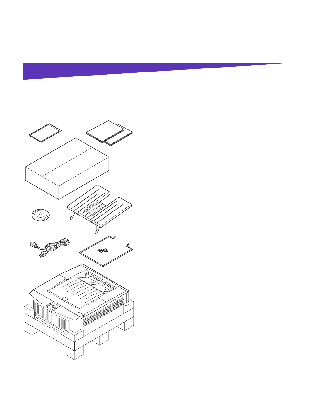
Step 1: Unpack the printer
1 Make sure you have all of the items listed below.
Quick Reference
CD
Pow er cord
and printer manuals
Print units
(in box)
Rear output bin
If any items are missing or damaged, refer to the
registration card for the designated Lexmark phone
number for your country.
Save the carton and packing materials in case you
need to repack the printer.
– Setup Guide, User’s Guide, and Quick Reference
– Box containing print units
– Rear output bin
– CD
– Power cord
– Extended paper support and hooks
– Printer
Hooks
Extended
paper
support
Printer
Unpack the printer
1
Page 8
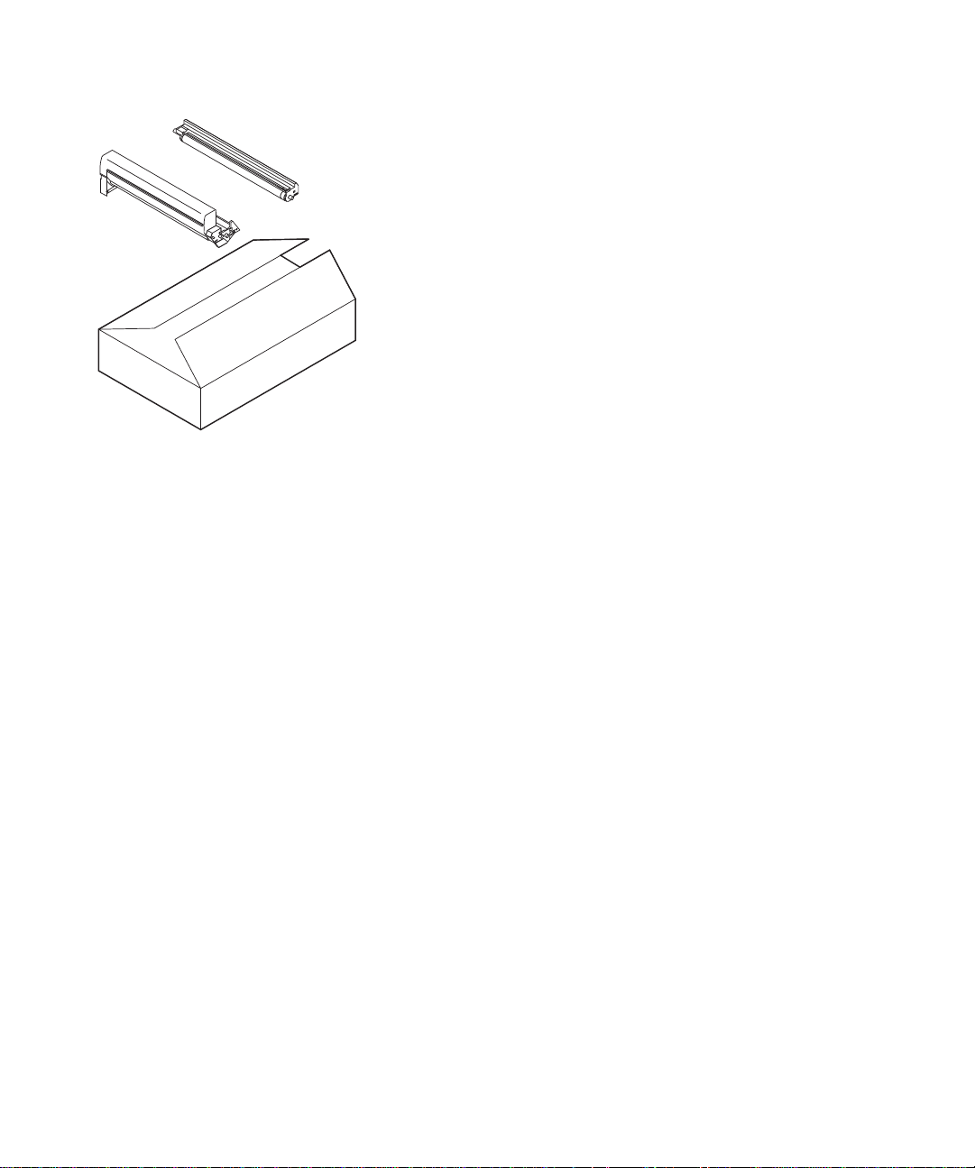
Toner
cartridge
Photoconductor
The print unit box includes:
• 4 color-coded toner cartridges
• 4 color-coded photoconductors
2
Unpack the printer
Page 9
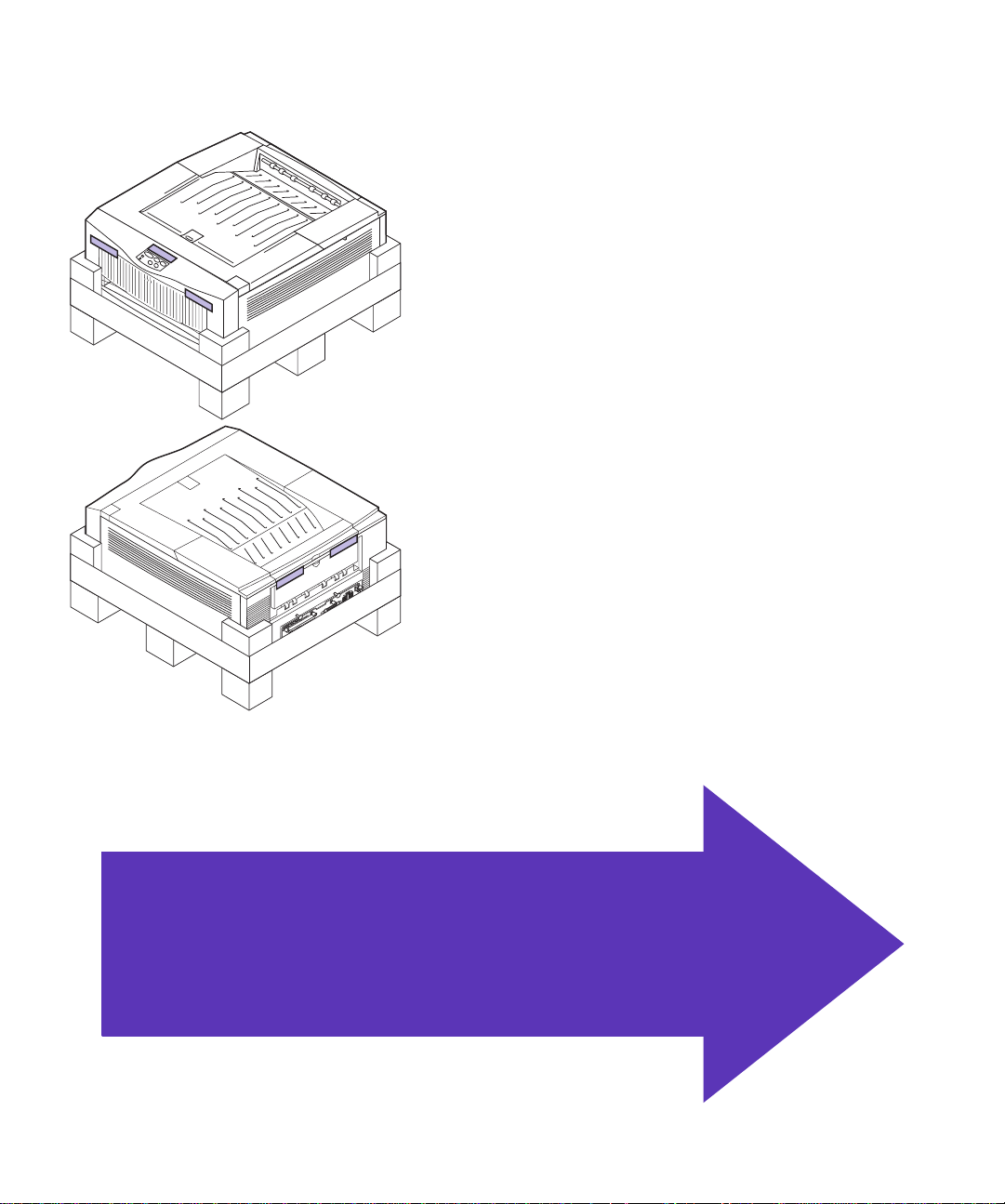
2
Remove any visible tape or other packing material
from the printer.
If you purchased an optional drawer, continue with Step 2: “Set up optional drawers” on
page 4. Otherwise, skip to Step 3: “Position
the printer” on page 13.
Unpack the printer
3
Page 10
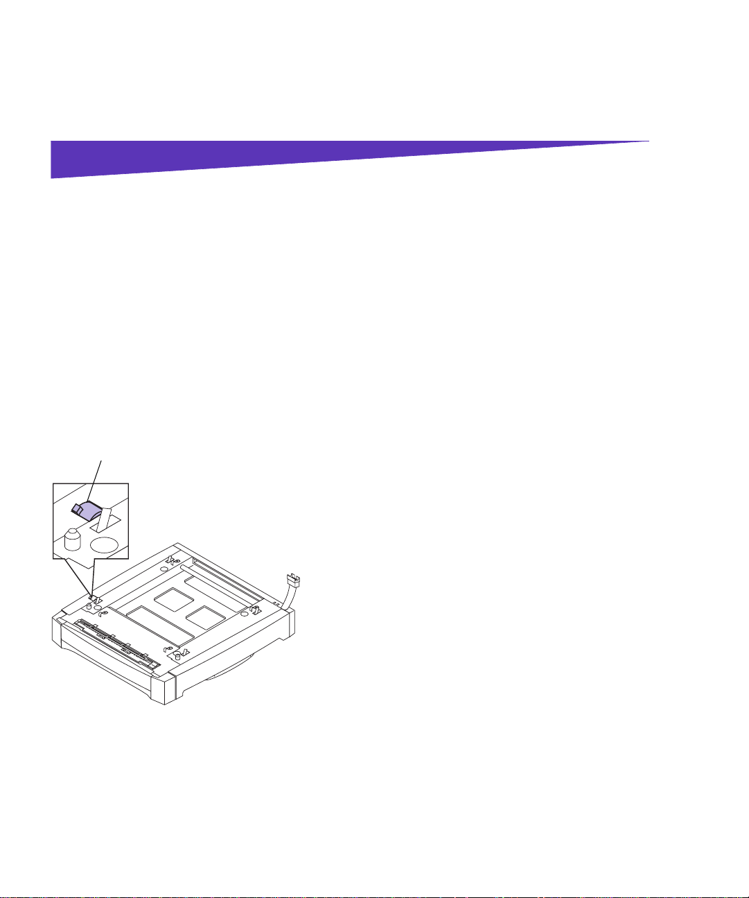
Step 2: Set up optional drawers
Your printer supports up to two optional 250-sheet drawers. If you are installing only one optional drawer, go to
“Connecting the printer to the drawer” on page 8. If you
are installing two drawers, complete the steps in the following section.
two drawers
Lock switch (unlocked)
Connecting
To attach one optional drawer to another:
1 Remove the drawers from the packing materials.
2
Place one drawer on a level surface.
3 Make sure the lock switch on the left side of the
drawer is unlocked.
4
Set up optional drawers
Page 11
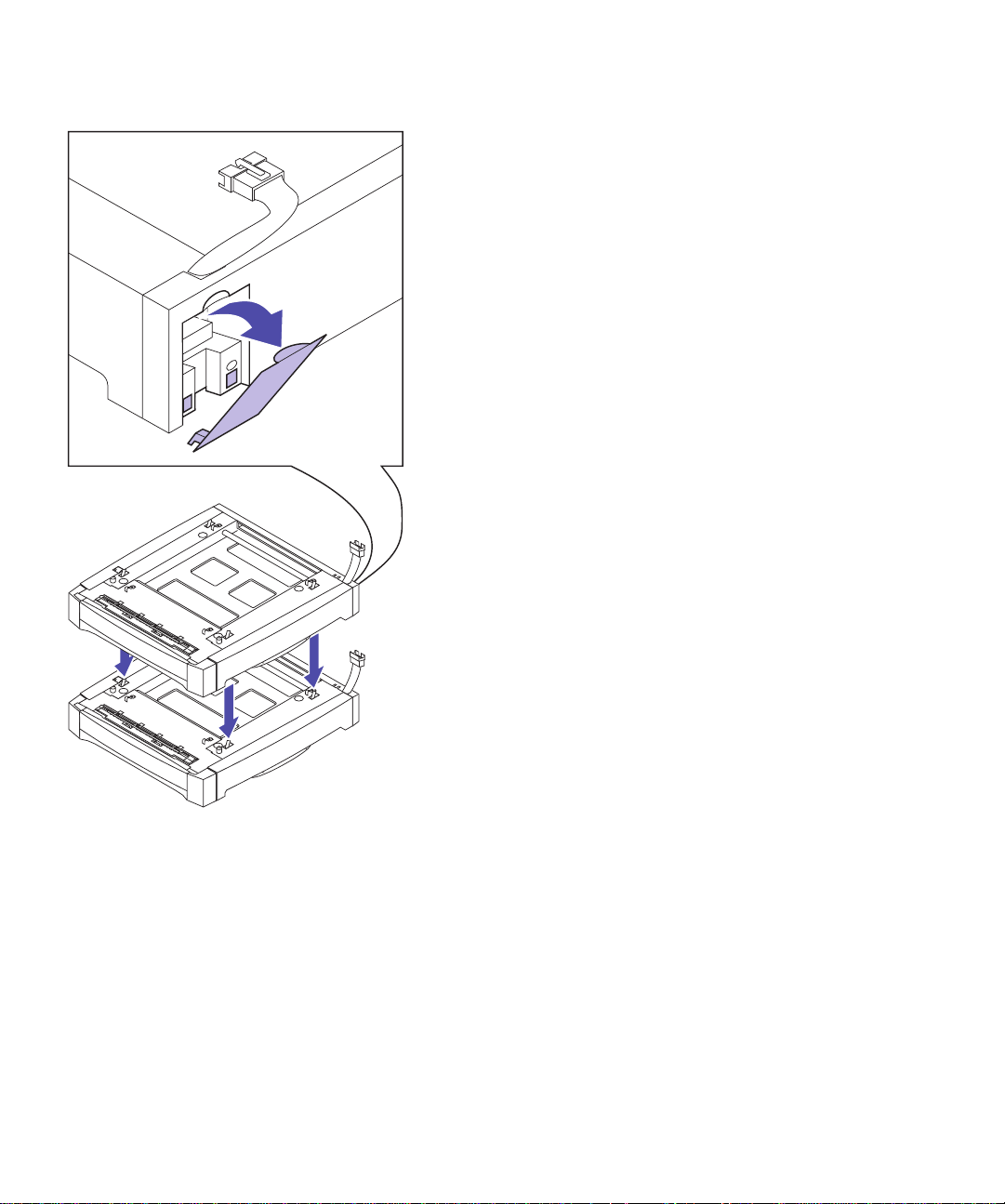
4
Remove the connector cover from the back of the
other drawer.
5
Set this drawer directly on top of the first, as
shown.
Set up optional drawers
5
Page 12
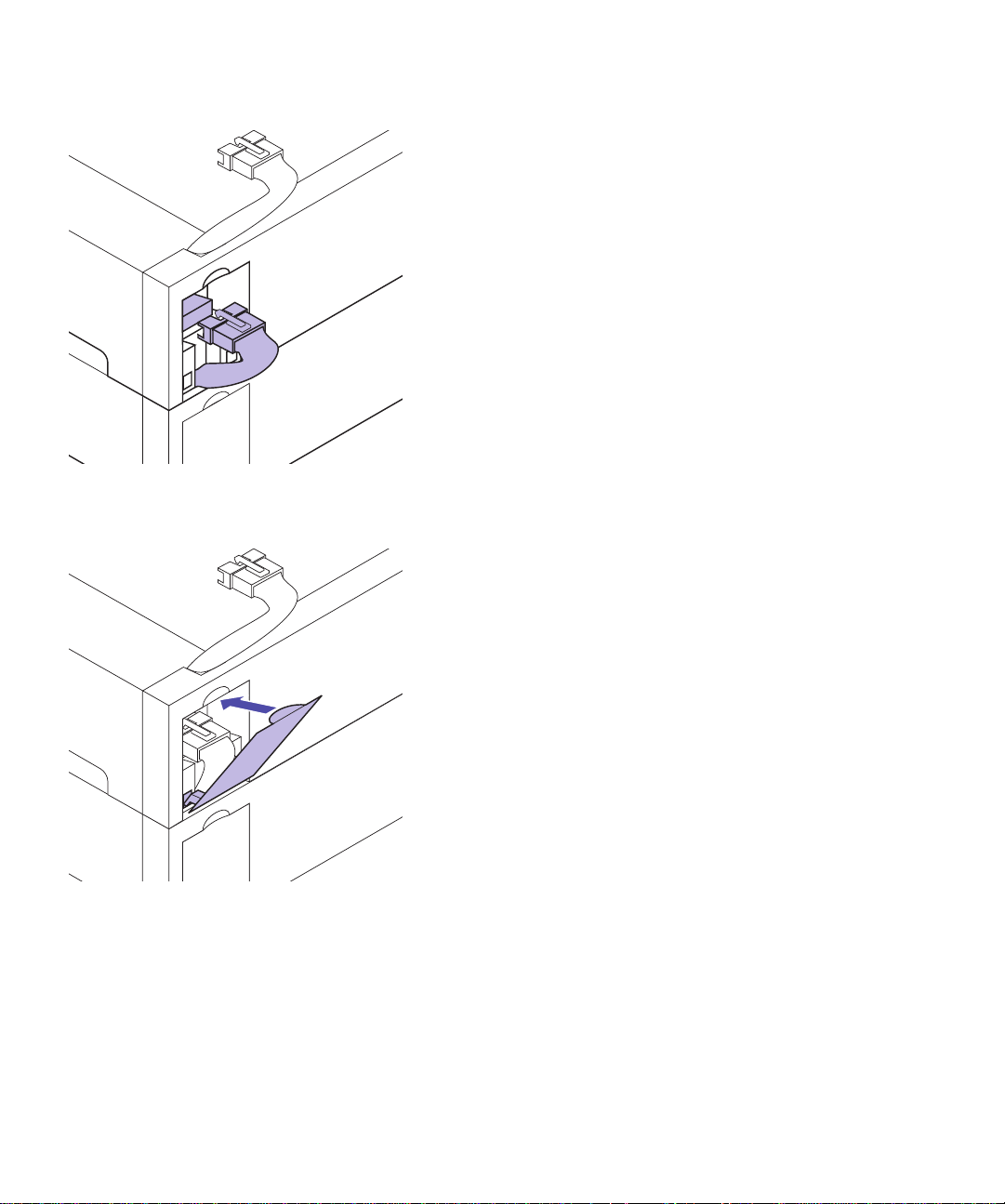
6
Plug the option cable from the lower drawer into
the connector on the upper drawer.
7 Reattach the connector cover on the upper drawer.
6
Set up optional drawers
Page 13
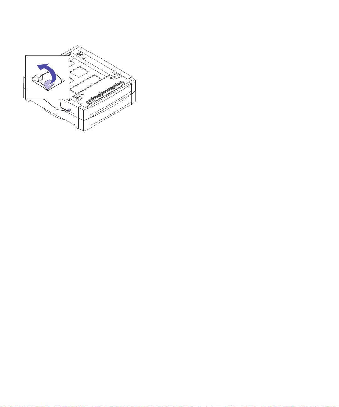
8
Locate the lock switch on the left side of the lower
drawer.
9
Push the lock switch toward the back of the
drawer to lock the options together.
10
Continue with “Connecting the printer to the
drawer” on page 8.
Set up optional drawers
7
Page 14
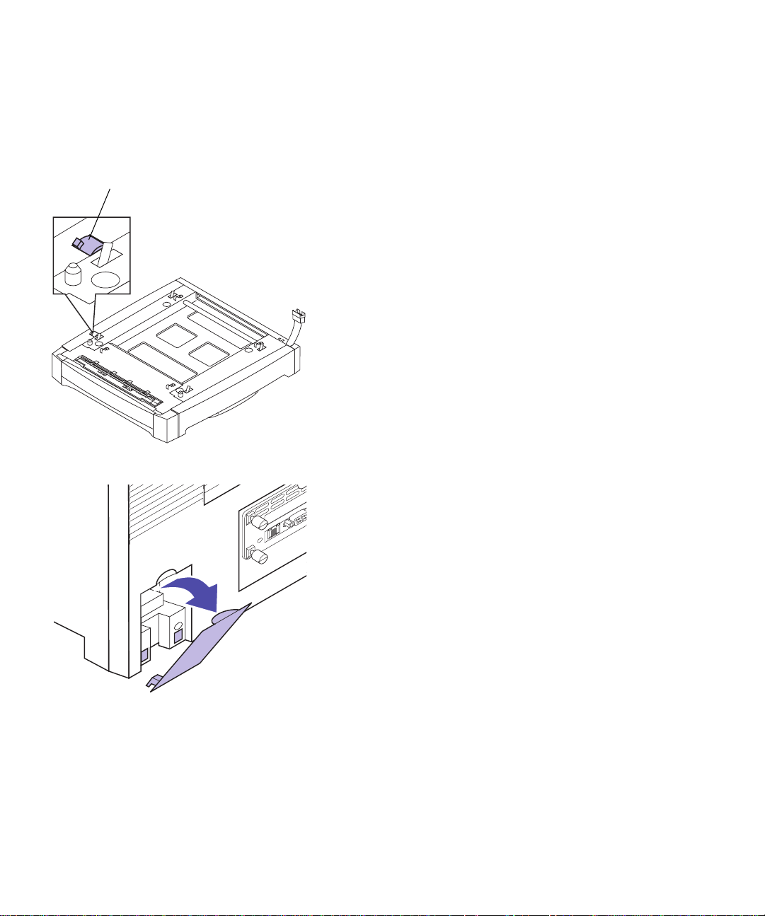
Connecting the
printer to the
Lock switch (unlocked)
drawer
Complete the following steps to attach the printer to one
or more optional drawers:
1 Remove the drawer from the packing materials.
2
Place the drawer (or the two drawers you already
connected) in the location you have chosen for
your printer.
See page 14 for more information about the appropriate environment for the printer.
3 Make sure the lock switch on the left side of the
drawer is unlocked.
4 Remove the connector cover from the back of the
printer.
5 If you’re installing the optional drawer sometime
after initial printer setup, turn the printer off and
disconnect the printer cables and the power cord.
8
Set up optional drawers
Page 15
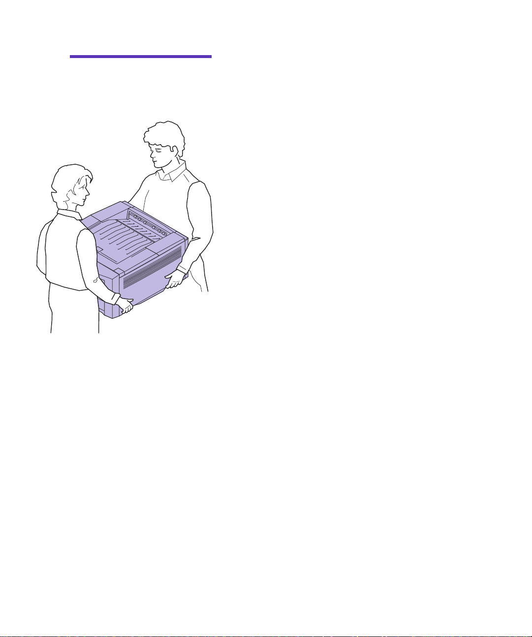
Caution!
43 kg (95 lb) and requires at
least two people to lift.
This printer weighs
6
Have someone help you lift the printer.
Use the handholds under the printer.
Set up optional drawers
9
Page 16
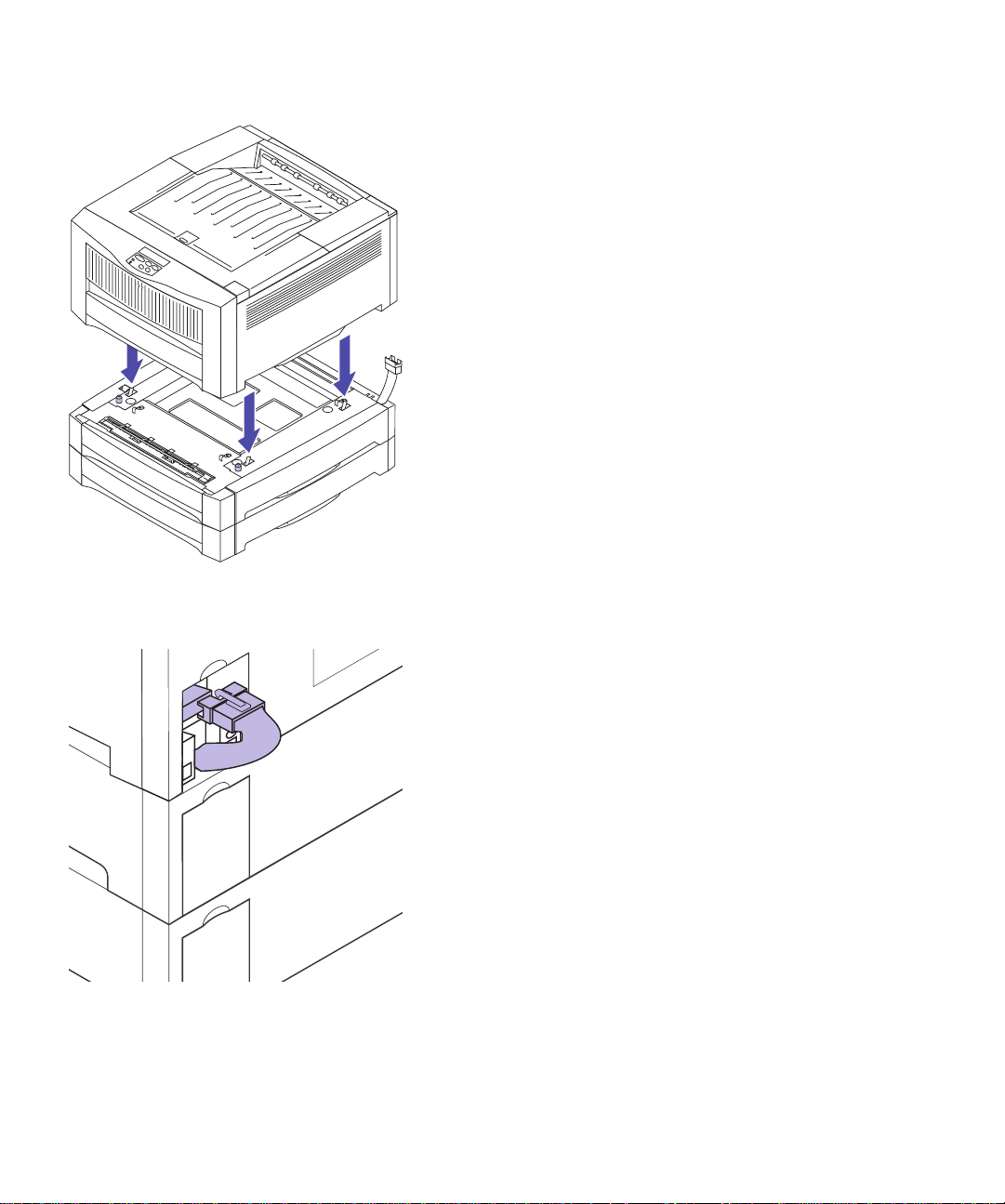
7
Carefully place the printer on top of the drawer(s),
as shown.
8 Plug the option cable from the drawer into the
connector on the back of the printer.
10
Set up optional drawers
Page 17
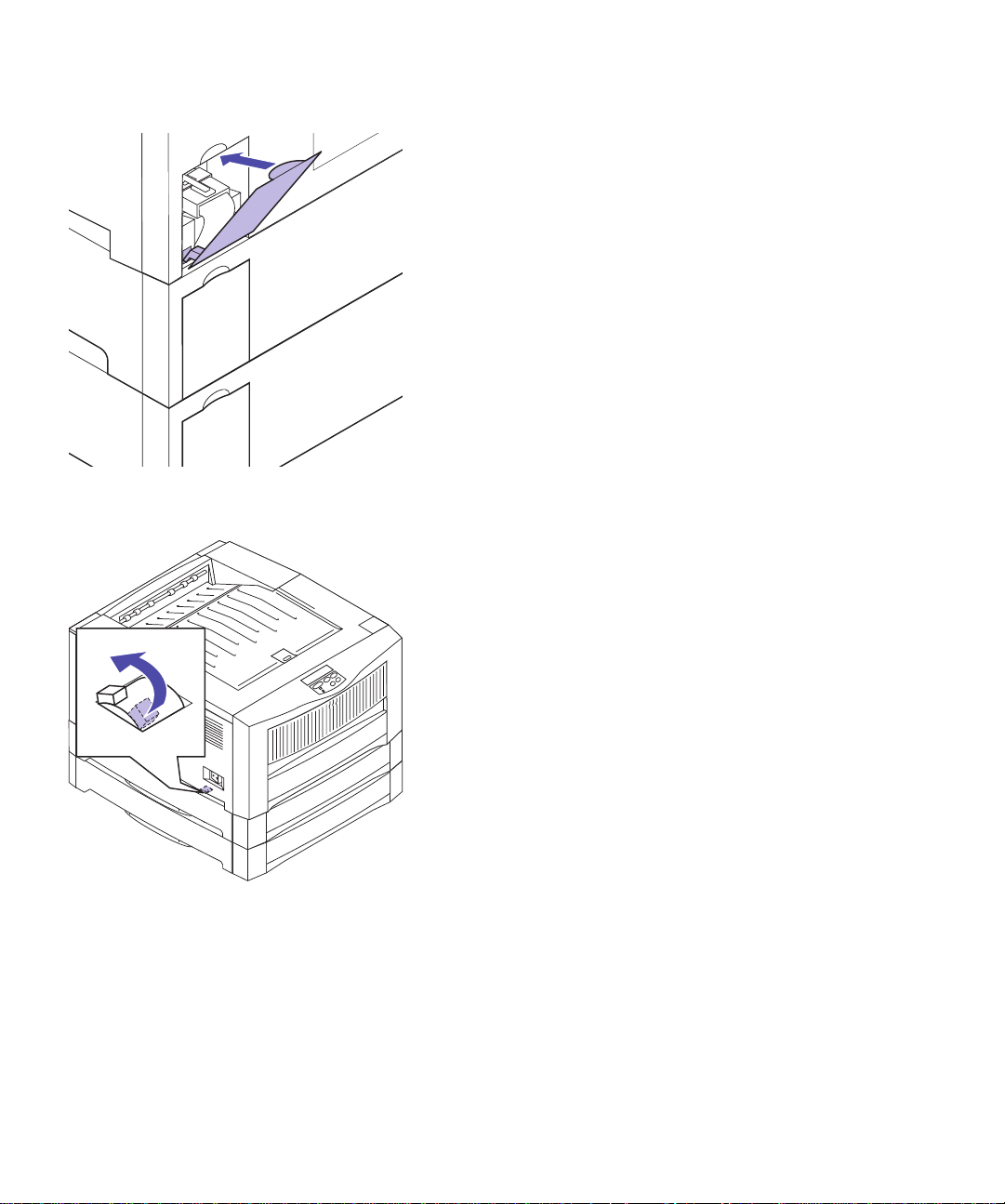
9
Reattach the connector cover on the back of the
printer.
10 Locate the lock switch on the left side of the
drawer.
11 Push the lock switch toward the back of the
drawer to lock the drawer to the printer.
Set up optional drawers
11
Page 18
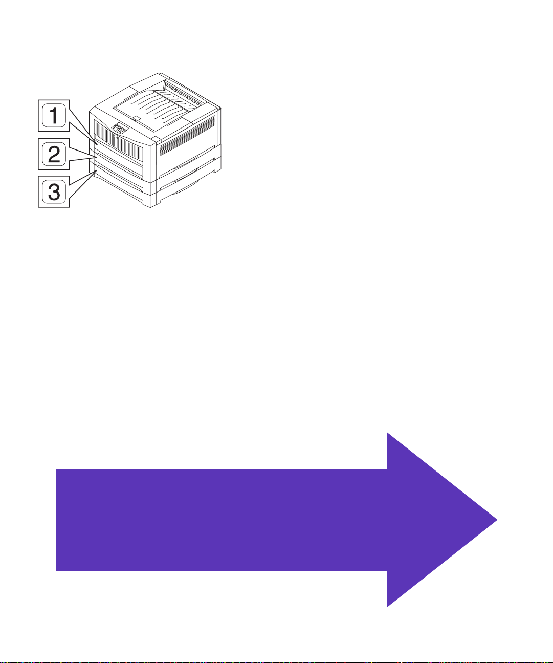
12
Attach the appropriate label to the front of each
tray.
The standard tray is tray 1. The optional trays are
tray 2 and tray 3, consecutively.
Instructions for loading paper in the trays begin on
page 23.
Skip to Step 4: “Install print units” on
page 15.
12
Set up optional drawers
Page 19

Step 3: Position the printer
Caution!
43 kg (95 Ib) and requires at
least two people to lift.
This printer weighs
1 Have someone help you lift the printer.
Use the handholds under the printer.
Position the printer
13
Page 20
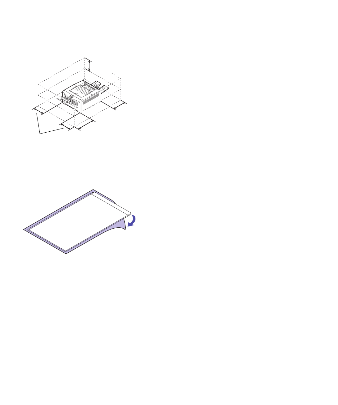
2
m
Place the printer on a flat, stable surface in a well–
ventilated area.
305 mm
(12 in.)
381 mm
(15 in.)
508 mm
(20 in.)
381 m
(15 in.)
Leave enough space in front of the printer to allow
for easy paper loading. If you plan to install the rear
output bin, leave room behind the printer as well.
Do not place the printer:
– In direct sunlight
– Near heat sources or air conditioners
– In dusty or dirty environments
3
Find a convenient location for the Quick Reference:
a
Locate a visible spot in the vicinity of the
printer or on the printer itself for the Quick
Reference.
b
Remove the protective paper from the back of
the plastic sleeve.
14
Position the printer
Quick Reference
c
Firmly attach the adhesive-backed sleeve to the
designated area.
Page 21
Step 4: Install print units
Assembling the
print units
Your printer ships with four color-coded toner cartridges
and four photoconductors. Together, the toner cartridge and
photoconductor create a color-specific print unit.
Complete the following steps to install each of the photoconductors into the appropriate toner cartridge:
1
Open the box containing the toner cartridges and
photoconductors.
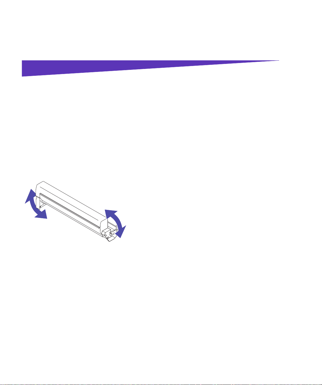
2 Remove a toner cartridge from the packing mate-
rial.
3 Gently shake the toner cartridge to distribute the
toner evenly.
4 Place the toner cartridge on a flat surface.
Install print units
15
Page 22
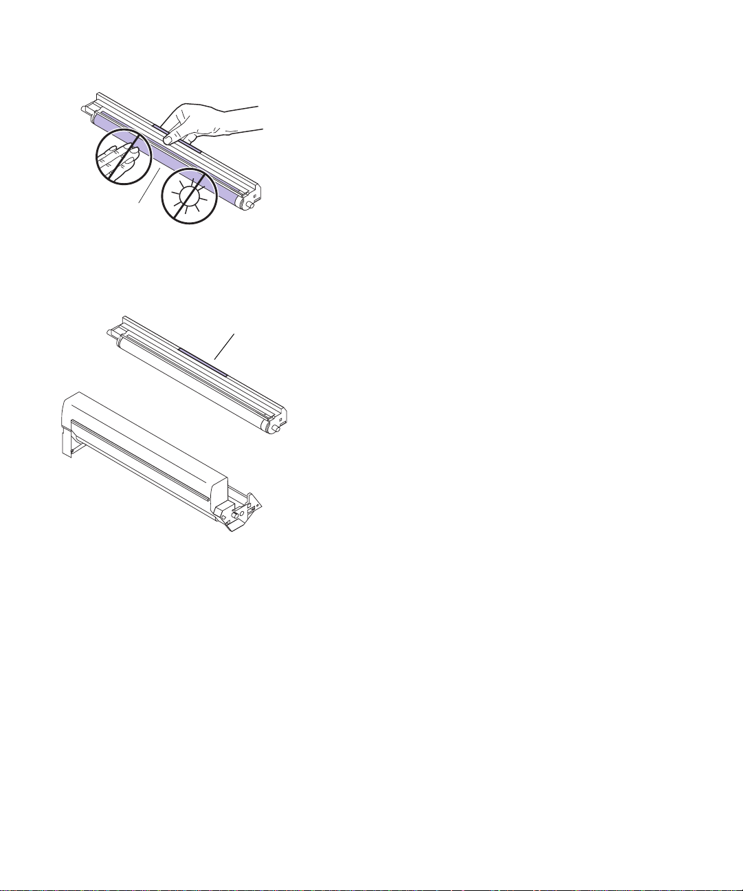
Drum
Handle
5
Remove the photoconductor with the same color
label as the toner cartridge from the packing mate-
rial.
To avoid damaging the photoconductor, do not
touch the glossy green surface of the drum.
Do not expose the photoconductor to light for more
than 10 minutes. If you need more time to assemble
and install the print units, cover the print units to
protect them from direct light.
6
Hold the photoconductor by the color-coded handle and position it above the toner cartridge, as
shown.
16
Install print units
Page 23
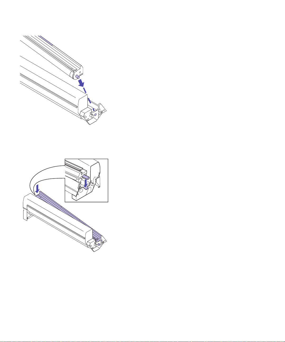
7
Slide the metal post on the right side of the photoconductor into the hole in the toner cartridge.
8
Insert the post on the opposite end of the photoconductor into the slot on the left side of the toner
cartridge.
Install print units
17
Page 24
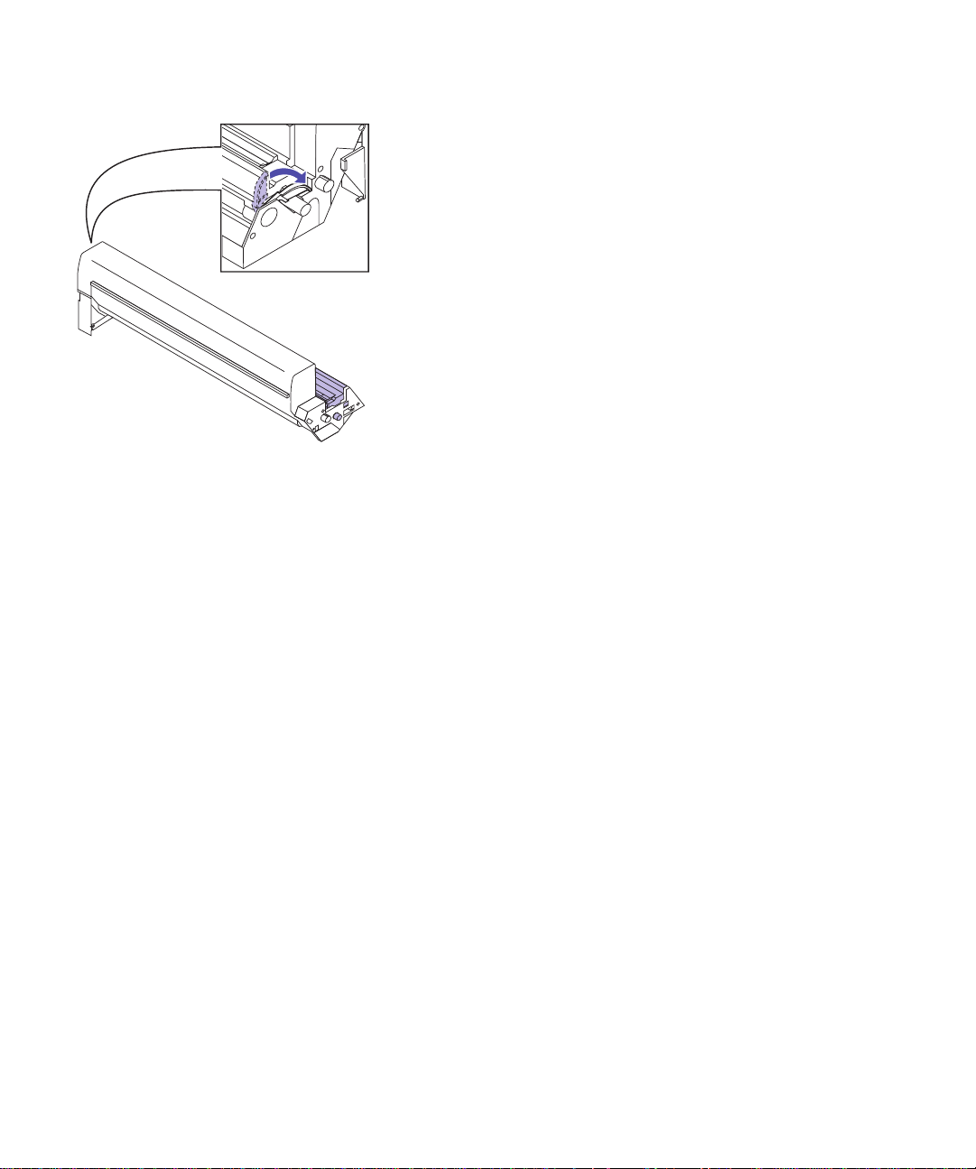
9
Rotate the green clip on the left end of the toner
cartridge, as shown, to lock the photoconductor in
place.
If the clip does not lock easily, make sure the photoconductor is properly positioned, and then try
again.
10 Repeat steps 1–9 for the remaining three
print units.
18
Install print units
Page 25

LEDs
Installing the
print units
Now that you’ve assembled the print units, you must
install them in the printer. Each color print unit has its
appropriate color-coded position in the printer.
Complete the following steps to install each print unit. We
recommend installing the magenta print unit first, followed by cyan, yellow, and black.
1 Press the release button on the printer’s top cover.
2 Raise the cover.
Do not touch the LEDs inside the top cover or the
transport belt in the bottom of the printer.
Transport belt
Install print units
19
Page 26

3
Pick up the print unit you are ready to install.
4 Press the large green tab on the print unit until it
clicks in place.
This opens the protective cover over the photoconductor drum. If the tab accidentally releases as you
install the print unit, press it again until it clicks in
place. You cannot install the print unit if the tab is
released.
Warning!
unit into the printer, or you may
damage the photoconductor. If
the print unit does not slide easily into place, make sure the
green tab is pressed in.
Do not force the print
5 Slide the print unit into the appropriate color-
coded position, as shown.
20
Install print units
Page 27

6
Press the print unit until it is completely seated.
7 Repeat steps 3–6 to install the remaining
print units.
8 After you have installed all four print units, gently
close the top cover until it clicks in place.
If the cover does not close easily, make sure each
print unit is installed correctly. Do not force the top
cover closed.
Install print units
21
Page 28

9
Close the rear cover.
22
Install print units
Page 29

Step 5: Load paper
Loading the
paper tray
Note:
cies in tray 1, make sure you
change the Paper Type setting
for that tray. See page 61 for
more information.
If you load transparen-
Your printer has one standard 250-sheet tray—tray 1—
that holds A4, A5, B4, B5, A3, letter, legal, and 11x17 size
paper. You can also load transparencies in tray 1. For
details about the types of media your printer supports,
refer to the User’s Guide.
If you attached an optional drawer or drawers, the
instructions are the same for loading paper in those trays.
However, load only paper in tray 2 and tray 3.
To load the tray:
1 Pull the paper tray completely out of the printer
and set it on a flat surface.
Load paper
23
Page 30

2 Squeeze the rear paper guide and slide it to the
appropriate position for the size paper you are
loading.
The position of the rear paper guide tells the printer
the size of the paper in the tray. If the rear paper
guide is in the wrong position, you may experience
paper feeding problems or incorrect formatting of
pages.
If you are loading A4 or letter size paper, the tray
may already be set up for the appropriate paper
size.
3 Before loading paper, flex the sheets back and
forth to loosen them, then fan them. Straighten the
edges on a level surface.
24
Load paper
Page 31

A4, A5, B5, and letter size paper
Maximum stack height
Corner tab
Long edge
B4, A3, legal, and 11x17 size paper
4 Load the paper with the recommended print side
face down, as shown.
Do not exceed the maximum stack height indicated
on the paper guides. Make sure the paper fits under
the two corner tabs at the front of the tray.
The orientation of the paper in the tray depends on
the size paper you’re loading:
– For A4, A5, B5, and letter size paper, place the
long edge of the paper at the front of the tray.
If you’re loading preprinted letterhead, place the
top of the page to the right.
– For B4, A3, legal, and 11x17 size paper, place the
short edge of the paper at the front of the tray.
Short edge
Maximum stack height
Corner tab
If you’re loading preprinted letterhead, place the
top of the page at the front of the tray.
The printer recognizes either B4 and A3 size
paper or legal and 11x17 size paper, depending
on the paper conventions in your geographic
region. If you need to change this printer setting,
refer to the information on the Size Detection
menu item in the User’s Guide.
Load paper
25
Page 32

5
Squeeze the right paper guide and slide both
width guides until they just touch the paper.
6
Hold the paper tray with both hands and firmly
slide it all the way into the printer.
26
Load paper
Page 33

Paper stop
7
If you’re printing on large paper, raise the paper
stop in the top output bin to neatly stack the
sheets as they exit the printer.
Load paper
27
Page 34

Loading the
multipurpose
feeder
You can load up to 100 sheets of paper, 30 transparencies,
30 sheets of labels, or 15 envelopes in the multipurpose
feeder. You can also use the multipurpose feeder for manually feeding single sheets of media. Refer to the User’s
Guide for more details about printing transparencies and
envelopes and general media support for the multipurpose feeder.
To load paper in the multipurpose feeder:
1 Firmly press the indentation on the front of the
multipurpose feeder to release the feeder, and
then lower it.
28
Load paper
Page 35

2
If you plan to print on longer paper (for example,
A3 or 11x17), insert the extended paper support
shipped with the printer.
The extended paper support may not be necessary
for smaller paper sizes. See page 35 for recommended storage of the extended paper support
when not in use.
a
Hold the metal support, as shown, with the
bent tips pointing toward the printer.
b
Insert the tips into the two holes at the front of
the multipurpose feeder.
c
Lower the support into place.
Load paper
29
Page 36

3
Flip open the standard paper support.
4
Before loading media, flex the sheets back and
forth to loosen them, then fan them. Straighten the
edges on a level surface.
30
If you’ve been using the multipurpose feeder and
need to load a new stack of media, press the bottom
of the feeder until it clicks into the loading position
before loading media.
Load paper
Page 37

A4, A5, B5, and letter size media
5 Load the sheets face up, as shown, and then slide
the right and left paper guides until they just
touch the stack.
The orientation of the media in the feeder depends
on the size media you’re loading:
– Position A4, A5, B5, and letter size media so the
long edge enters the printer first.
If you’re loading preprinted letterhead, place the
top of the page to the right.
B4, A3, legal, and 11x17 size media
– Position B4, A3, legal, and 11x17 size paper so
the short edge enters the printer first.
If you’re loading preprinted letterhead, position
the top of the page so it enters the printer first.
Load paper
31
Page 38

Envelopes
– Load envelopes flap-down, short-edge first, as
shown.
Do not load stamped envelopes.
6
Press the green release lever to the left to position
the media for printing.
32
Refer to the User’s Guide for more information about
printing from the multipurpose feeder.
Load paper
Page 39

Closing the
multipurpose
feeder
To close the multipurpose feeder after you have finished
printing:
1 Press the bottom of the feeder until it clicks.
2 Slide the paper guides all the way out.
Load paper
33
Page 40

3
Fold in the standard paper support.
4 Remove the extended paper support, if installed.
a
Rotate the support to a near vertical position.
b
Pull the support out of the multipurpose
feeder.
34
Load paper
Page 41

5
Close the multipurpose feeder.
6 Store the extended paper support.
a
Attach the adhesive backed hooks shipped
with the printer to the right side of the printer,
as shown.
b
Hang the extended paper support on the hooks
when the multipurpose feeder is not in use.
Make sure the tips of the support wrap around
the back of the printer, as shown.
Load paper
35
Page 42

Posts
Attaching the
rear output bin
If you plan to load transparencies, envelopes, labels, or
card stock in the multipurpose feeder, you may want to
attach the rear output bin to the back of the printer. This
creates a straight paper path for the media and prevents
curling.
If you attach the rear output bin, you must remove it to
access the printer system board or connect cables to the
back of the printer.
To install the rear output bin:
1 Remove the bin from the packing materials.
2 Locate the two posts at the back of the printer.
3
Align the arrow on the bin with the arrow above
the right post.
36
Load paper
Page 43

4
Hold the bin flush against the back of the printer.
5 Press the bin straight down, so the slots in the bin
slide firmly over the posts.
If you purchased memory or disk options, or a
network, tri-port, or parallel port adapter, continue with Step 6: “Install memory and network
options” on page 38. Otherwise, skip to Step 7:
“Attach cables” on page 53.
Load paper
37
Page 44

Step 6: Install memory and
network options
You can add memory and interface ports to your printer
by installing the following options:
• Printer memory
• Hard disk
• Network adapter
• Tri-port adapter
• Parallel port adapter
38
Removing the
system board
Install memory and network options
You must remove the system board to install memory
cards, a hard disk, network adapter, tri-port adapter, or
parallel port adapter. Instructions for reinstalling the system board begin on page 52.
To remove the system board:
1 If you are installing options after initial printer
setup, make sure the printer power is off and the
power cord is unplugged.
Page 45

2
If the rear output bin is attached to the back of the
printer, lift it straight up and remove it from the
printer.
3 Disconnect all cables from the back of the printer.
If you installed an optional drawer, you do not need
to unplug the option cable.
4 Loosen the six thumbscrews on the system board
faceplate at the back of the printer.
Install memory and network options
39
Page 46

5
Slide the system board completely out of the
printer and place it on a level surface.
6 Turn to the appropriate section for instructions on
installing your options.
Installing options
Option See…
Printer memory “Installing memory pairs” on
Hard disk “Installing a hard disk” on
Network adapter
Tri-port adapter
Parallel port adapter
page 41
page 45
“Installing adapters” on page 48
40
Install memory and network options
Page 47

Installing
memory pairs
Your printer comes with two 16MB memory cards already
installed, for a total of 32MB of standard memory. (Some
printer models may have more standard memory.) You
can purchase two different memory options from Lexmark: a 32MB option that includes two 16MB cards, and a
64MB option that includes two 32MB cards. Since your
printer has four memory connectors, you can therefore
install up to a maximum of 128MB of memory.
Note:
50ns Extended Data Out (EDO)
memory cards that must be
installed in pairs. Memory
options designed for other Lexmark laser printers do not work
with your printer. Refer to the
User’s Guide
tion.
Memory
connectors
Your printer requires
for more informa-
You must always install memory cards in pairs, each with
the same amount of memory. For example, to install 64MB
of memory, you must install two 32MB cards or four 16MB
cards.
To install optional memory:
1 Complete the steps in “Removing the system
board” on page 38.
2 Locate the memory connectors on the system
board.
The two standard memory cards are installed in the
far left connectors.
Install memory and network options
41
Page 48

Warning!
easily damaged by static electricity. Touch something metal
before you touch a card.
Memory cards are
3 Complete the following steps if you need to
remove a pair of memory cards before you install
new ones. Otherwise, skip to step 4 on page 43.
a
Push the metal clips at each end of the connector away from the rightmost card.
b
Rotate the card toward the right.
42
Install memory and network options
c
Gently pull the card out of the connector.
d
Place the card in its original packaging.
If you did not save the packaging, wrap the card
in paper and store it in a box.
e
Repeat steps a–d to remove the second memory
card.
Page 49

Connection points
4
Unpack the new memory card.
Unpack each memory card separately just before
installing it. Avoid touching the connection points
along the edge of the card. Save the packaging.
5 Hold the memory card with the connection points
pointing toward the system board and the notch
positioned as shown.
Notch
6 Insert the card all the way into the leftmost open
connector at a 45 degree angle.
7
Rotate the card to the left until it snaps into place.
When the memory card is correctly installed, it sits
at a sharp angle to the system board.
Install memory and network options
43
Page 50

Clip
Pins
Clip
8
Make sure both metal clips on the connector are
fastened, and the two pins on each end of the con-
nector are pushed through the holes on the card.
9 Repeat steps 4–8 to install the other memory card
or cards.
10 If you have other options to install, continue with
“Installing a hard disk” on page 45 or “Installing
adapters” on page 48. Otherwise, go to “Reinstalling the system board” on page 52.
44
Install memory and network options
Page 51

Installing a
hard disk
Two hard disk options are available from Lexmark:
• A hard disk with a ribbon cable already installed.
• An adapter ribbon cable alone that you can use to
install any other Lexmark or third-party hard disk
meeting the following criteria:
– 2.5-inch platter
– ATA-2 (IDE) interface
– Maximum thickness of 13 mm (.51 in.)
Stripe
Attaching an
adapter ribbon cable
If you bought an adapter ribbon cable for a separate hard
disk, follow these instructions to attach the cable to the
disk. If your disk already has a ribbon cable attached, skip
to “Installing the disk” on page 46.
The adapter ribbon cable comes with screws for securing
the hard disk to the system board.
1 Locate the 47-hole connector on the ribbon cable.
One of the 50-hole connectors has three holes
plugged.
2 Carefully attach the 47-hole connector to the disk
connector.
When correctly installed, the stripe on the ribbon
cable should be oriented as shown.
3 Continue with “Installing the disk” on page 46.
Install memory and network options
45
Page 52

Disk bracket
Installing the disk
You need a Phillips screwdriver to install the disk.
1 Complete the steps in “Removing the system
board” on page 38.
2 Locate the disk bracket underneath the system
board.
3 Hold the hard disk so the ribbon cable extends
upward.
4 Slide the disk all the way into the bracket.
46
5 Insert the screws provided with the option into the
back of the system board. Securely tighten the
screws.
Install memory and network options
Page 53

6
Connect the ribbon cable to the connector on top
of the system board.
If you have trouble connecting the cable, make sure
all four screws are securely attached to the back of
the disk.
7 If you have other options to install, continue with
“Installing adapters” on page 48. Otherwise, go to
“Reinstalling the system board” on page 52.
Install memory and network options
47
Page 54

Installing
adapters
You can install the following adapters in your printer:
• Internal network adapter
• Tri-port adapter
• Parallel port adapter
Note:
printer model, you may already
have an Ethernet INA installed in
connector 1.
Depending on your
An internal network adapter (INA), such as the
MarkNet
network (LAN). MarkNet S adapters support the following topologies:
The tri-port adapter provides connectors for the following:
The parallel port adapter provides an additional
parallel port. Its 1284C connector requires a 1284 A–C
cable. You can purchase a 3 m (9.8 ft) cable meeting these
specifications from Lexmark.
Refer to the documentation that came with your adapter
for more information.
There are two adapter connectors on your system board:
connector 1 and connector 2. Both connectors support network, tri-port, and parallel port adapters.
TM
S, lets you connect the printer to a local area
• Ethernet 10BaseT and 10Base2
• Ethernet 10/100BaseTX
• To k en - R i ng
• Serial interface (RS-232C or RS-422), which can also
serve as a receive-only fax port
• LocalTalk network
• An infrared adapter
48
Connector 2
Connector 1
Install memory and network options
You can install up to two adapters in any combination. If
you install two tri-port adapters, your printer can support
two serial ports (but only one receive-only fax port), one
LocalTalk port, and one infrared port.
If you are installing one adapter, install it in connector 1.
You can then easily install a second adapter in connector 2.
If you already have an adapter installed in connector 2
and you want to install a second adapter, you must first
remove the adapter in connector 2, and then install the
adapters in connector 1 and connector 2 in sequence.
Page 55

To install an optional adapter:
Warning!
ily damaged by static electricity.
Touch something metal before
you touch an adapter.
All adapters are eas-
1 Complete the steps in “Removing the system
board” on page 38.
2 Complete the following steps if you need to
remove an adapter before you install another one.
Otherwise, skip to step 3 on page 50.
a
Remove the two screws on either end of the
opening for the cable connectors.
b
Gently pull the adapter completely out of the
system board connector.
c
Angle the adapter away from the system board.
d
Place the adapter in its original packaging.
If you did not save the packaging, wrap the
adapter in paper and store it in a box.
Install memory and network options
49
Page 56

Metal plate
e
If you are not installing another adapter in the
connector, cover the opening, preferably with
one of the metal plates designed for that purpose.
Covering the opening ensures proper airflow
around the system board. If you do not have a
metal plate, contact your service representative
and request a blank cover for the controller cage.
3
Before installing an adapter, remove the metal
plate covering the opening for the cable connec-
tors.
a
Remove the two screws on either end of the
metal plate.
Save the screws. You’ll use them to secure the
adapter to the system board.
b
Remove the plate.
Save the metal plate so you can reinstall it if you
remove the adapter.
4 Unpack the adapter.
50
Save the packing materials.
5 Angle the adapter, as shown, so the cable connec-
tors on the adapter fit through the opening in the
faceplate.
Install memory and network options
Page 57

6
Align the adapter connector with the connector on
the system board.
7
Push the adapter firmly into the system board connector until it is completely seated.
The two connectors should fit snugly together.
8 Insert the two screws saved from the metal plate
(or the extra screws shipped with the adapter) into
the holes on either end of the opening for the
cable connectors.
9 Gently tighten the screws to secure the adapter.
10 Repeat steps 3–9 to install a second adapter in
connector 2.
11 Continue with “Reinstalling the system board” on
page 52.
Install memory and network options
51
Page 58

Reinstalling the
system board
After you have installed all options on the system board,
complete the following steps to reinstall the system board:
1
Align the system board with the printer opening,
as shown.
2
Rest the system board on the lip at the front of the
opening.
3 Carefully slide the system board all the way into
the printer.
52
Security tab
Install memory and network options
The security tab on the right side of the printer
should fit through the slot in the faceplate. You can
attach a padlock to the security tab to prevent access
to the system board.
4 Firmly press the faceplate in the area indicated by
the arrow.
This ensures the connector on the back of the system
board inserts completely into the connector at the
back of the printer opening.
5 Securely tighten the six thumbscrews on the sys-
tem board faceplate.
6 If necessary, reattach the rear output bin.
If you have trouble installing the bin, make sure the
screws on the system board faceplate are completely
inserted.
Page 59

Step 7: Attach cables
You can attach the printer to a LAN by:
• Connecting the printer directly to the server using a
parallel or serial cable.
Your printer’s standard parallel port requires an
IEEE-1284 compliant parallel cable. We recommend
Lexmark part number 1329605 (10 ft) or 1427498
(20 ft). If you installed an optional parallel port
adapter, you need a 1284 A–C parallel cable, such as
Lexmark part number 43H5171 (9.8 ft). If you use
something other than an IEEE-compliant cable, you
may not be able to access all of your printer’s functions.
If you’re attaching a serial cable, we recommend
Lexmark part number 1038693 (50 ft). Attach the
cable to the serial connector on the optional tri-port
adapter you installed in the printer.
• Connecting the printer directly to the LAN:
– Using an external network adapter (ENA), such
as Lexmark’s MarkNet Pro or MarkNet XLe
adapter
– Using an internal network adapter, such as the
MarkNet S described on page 48
– Using the optional tri-port adapter to connect to
a LocalTalk network
For more information about your particular adapter,
refer to the documentation that came with the
adapter.
Attach cables
53
Page 60

Optional parallel,
serial, or network
connectors
Standard parallel
connector
To attach a cable to your printer:
1 Make sure the printer power is off and the power
cord is unplugged.
2 If the rear output bin is attached to the back of the
printer, lift it straight up and remove it from the
printer.
3 At the back of the printer, locate the parallel,
serial, or network cable connector.
One parallel connector is standard. Additional parallel connectors and the serial and network
connectors are attached to the adapters installed in
the printer.
54
4 Connect the appropriate cable.
5 Reattach the rear output bin, if necessary.
Attach cables
Page 61

Connecting
an external
fax modem
If you installed an optional tri-port adapter in your
printer, you can attach an external, class 1 fax modem to
the serial port on the adapter. You can then use your
printer to receive faxes.
Faxes received print in black only. You cannot send faxes
from your printer.
To set up the serial port to receive faxes:
Power cord
External class 1
fax modem
Phone cord
Modem
cable
To prin ter
serial port
1 Make sure the printer power is off and the power
cord is unplugged.
2 Turn the modem power off.
3
Follow the instructions included with the modem
to connect the modem to the serial port.
The modem connects to the printer in the same way
it would connect to a computer. Make sure the
modem cable has a 25-pin connector to attach to the
serial connector on the printer.
4 Turn the modem power on.
You must turn on the modem before you turn on the
printer.
5
Turn the printer power on.
6 From the printer operator panel:
a
Press the
menus.
b
Continue to press
FAX MENU
Menu>
.
or
<Menu
Menu>
button to enter the
<Menu
or
until you see
c
Press the
Fax Port
d
Press
Select
button.
appears on the second line of the display.
Select
again.
Attach cables
55
Page 62

e
Menu>
Press
want to set up as a fax port appears on the second line of the display.
For example, if you installed a tri-port adapter in
connector 2,
<Menu
or
look for
until the serial port you
Ser Option 2
.
Note:
figure the serial port for multiple
uses with an A-B switch.
Do not attempt to con-
f
Refer to the printer User’s Guide for information about
changing the fax communication settings, such as baud
and parity.
To disable the fax modem and restore the printer serial
port to normal use:
Select
Press
The printer resets. You are now ready to receive
faxes.
.
1 From the printer operator panel:
a
Press the
menus.
b
Continue to press
FAX MENU
c
Press the
Fax Port
d
Press
e
Press
the second line of the display.
Menu>
.
Select
appears on the second line of the display.
Select
again.
Menu>
or
<Menu
or
Menu>
button.
<Menu
until
button to enter the
<Menu
or
Disabled
until you see
appears on
56
Attach cables
f
2
Turn the modem power off.
Select
Press
The printer resets.
.
3 Turn the printer power off.
4 Disconnect the modem cable from the printer
serial port.
5 Turn the printer power on.
Page 63

Connecting an
infrared adapter
You can use an infrared adapter to print remotely from a
computer equipped with an infrared port.
The optional tri-port adapter, which includes an infrared
port, lets you connect the infrared adapter to your printer.
After you have installed the tri-port adapter, follow the
steps below to connect the infrared adapter to your
printer:
1 Make sure the printer power is off and the power
cord is unplugged.
2 Locate the infrared port at the back of your printer.
The infrared port is attached to the tri-port adapter
you installed earlier.
3 Plug the adapter cable into the infrared port.
4
Plug in the printer power cord and turn on the
printer.
If any light on the infrared adapter comes on when
the printer power is on, the adapter is plugged into
the printer port correctly.
Attach cables
57
Page 64

5
Draw an imaginary line between the infrared port
on the computer and the infrared port on the front
of the adapter.
Refer to the documentation that came with your
computer for information about your computer’s
infrared port.
6 Aim the infrared port on your computer within
15 degrees of either side of this line, as shown.
58
Attach cables
Page 65

Step 8: Verify setup
Print the menu settings page to review the default printer
settings and to verify that printer options are installed correctly. For more information about using the printer operator panel and changing menu settings, refer to the User’s
Guide.
1 Make sure the printer is turned off (O).
2
Plug one end of the power cord into the connector
at the back of the printer and the other end into a
properly grounded electrical outlet.
Power switch
3 Turn the printer on ( | ).
Installing new photoconductors adds to the warmup time the printer requires after you turn it on.
During this period, the messages
Engine Warming
and
display. After the printer completes its internal tests,
Ready
the
status message is displayed.
appear on the operator panel
Performing Self Test
Verify setup
59
Page 66

Ready
Supplies
If Power Saver is set On (the factory default),
Power Saver
the specified period of time. Both messages indicate
that the printer is ready to receive print jobs. Refer
to the User’s Guide for more information about modifying the Power Saver setting.
replaces the
Ready
status message after
Menu
Select
Go
Return
Stop
Printing the
menu settings
page
Note:
menu settings page, make sure
the selected paper source holds
A4, letter, or legal size paper
and the Paper Type setting for
the source is Plain Paper.
Before printing the
If an error message is displayed, refer to the User’s
Guide for helpful tips.
Complete the following steps to print the menu settings
page. Refer to the User’s Guide for more information about
using the printer operator panel and changing settings
from the menus.
or
Menu>
<Menu
or
until
1 From the printer operator panel, press the
<Menu
button to enter the menus.
2 Continue to press and release
you see
3
Press the
TESTS MENU
Print Menus
4 Press
The message
printer returns to
tings page prints.
TESTS MENU
Select
Select
is then displayed on the first line, and
is on the second line
again to print the page.
Printing Menu Settings
.
button.
Ready
status after the menu set-
Menu>
.
is displayed. The
60
If an error message appears on the display, refer to
the User’s Guide for more information.
Verify setup
Page 67

5
Verify that the options you installed are listed on
the menu settings page under “Installed Fea-
tures.”
If an option you installed does not appear on the
page, turn the printer off, unplug the power cord,
and reinstall the option.
6
If you attached a serial cable, verify that the
printer serial settings listed on the menu settings
page are appropriate for your system.
Refer to the User’s Guide for more information about
the Serial Menu and changing these settings.
Changing the
Paper Type
setting
It is important to verify that the Paper Type settings are
accurate for all the installed paper sources. Refer to the
menu settings page you printed. The Paper Type is listed
for each of the installed paper sources.
Paper Type refers to the type of media loaded in the
sources: plain paper, letterhead, envelopes, transparencies, card stock, a custom media you define, and so on.
Since different sources can hold different media, you can
customize the Paper Type setting for each source.
The printer uses the Paper Type setting to optimize print
quality for the media you specified. For example, selecting
the Transparency paper type causes the printer to heat the
fuser to a higher temperature and slows printing to produce the best transparency possible. The Paper Type setting also affects the printer’s automatic source selection
capability, as well as the tray linking function. For these
reasons, it’s important to change the setting each time you
change the media in the tray or feeder.
Refer to the User’s Guide for more detailed information
about the paper types supported by each paper source, as
well as ways to use the Paper Type setting to make printing more efficient in your work environment.
Verify setup
61
Page 68

If you need to change a Paper Type setting:
1 From the printer operator panel, press the
<Menu
button to enter the menus.
PAPER MENU
play.
2 Press the
3 Press and release
on the second line
4 Press
5 Press
6 Press
Select
Tray 1 Type
Select
Type setting.
Menu>
sible paper types for tray 1.
appears on the second line of the dis-
Select
button to open the Paper Menu.
Menu>
.
.
appears on the second line of the display.
again if you want to change the Tray 1
<Menu
or
to scroll through a list of pos-
until
PAPER TYPE
Menu>
or
appears
7 When the correct paper type appears on the second
line of the display, press
type as the default for tray 1.
Select
again to save the
8 If you need to change the Paper Type setting for
another source, press
priate source, and then repeat steps 5 through 7.
Menu>
to scroll to the appro-
62
Verify setup
9 When you are finished changing the Paper Type
settings, press the
to the ready state.
Go
button to return the printer
Page 69

Printing an
adapter setup
page
If you installed a network adapter and want detailed
information about the option and the active protocols, follow the instructions below to print the adapter setup page:
1 From the operator panel, press
enter the menus.
Menu>
or
<Menu
to
2
Continue to press and release
you see
3
Press
Network Option 1
second line of the display. If necessary, press
or
4 Press
5 Press
SETUP
6 Press
7 Press
ond line of the display.
8 Press
Print Setup Page
display.
9 Press
NETWORK MENU
Select
.
Network Option 2
or
<Menu
to display the correct network option.
Select
again.
Menu>
on the second line of the display.
Select
Menu>
Select
Select
<Menu
or
.
or
.
to print the page.
until you see
<Menu
until you see
appears on the second line of the
Menu>
.
appears on the
NETWORK x
Print
<Menu
or
on the sec-
until
Menu>
Verify setup
63
Page 70

Step 9: Load MarkVision and
drivers
The compact disc (CD) shipped with your printer contains
printer drivers and utilities for Windows 95, Windows NT
4.0, Windows 3.1x, Macintosh, OS/2, and DOS environments. Drivers are available for both PostScript Level 2
and PCL printer languages.
Refer to the CD Readme for a complete list of all the drivers included on the CD. Updated drivers, as well as a complete description of the driver packages and Lexmark
driver support, are also available electronically from the
Lexmark web site on the World Wide Web. Refer to the
User’s Guide for more information about getting updated
drivers.
To support all the printer’s features, install the custom
Lexmark drivers on your system. If you use drivers
designed for printers other than the Optra Color 1200, you
may not be able to control all of the printer’s functions.
For more information about these functions, refer to the
driver online Help or to the printer User’s Guide.
64
Load MarkVision and drivers
In addition to printer drivers, you may be particularly
interested in installing the MarkVision
MarkVision provides numerous printer management tools
that can help you set up a network of printers, monitor the
status of the printers, and collect information about
printer use. For more information about MarkVision features and installation, refer to the MarkVision documentation on the CD or in the printer User’s Guide.
TM
printer utility.
Page 71

Note:
quent access to a CD-ROM
drive, you can create installation
diskettes from the CD.
If you only have infre-
1
Launch the CD.
Refer to the booklet included with the CD for information about launching the CD program for your
operating system.
When you launch the CD, the CD program displays
icons or text items that let you choose what you
want to do.
If necessary, you can change the language of the text
the CD displays on the screen. This also changes the
language of the text displayed on the user interface
screens for the drivers and utilities you choose to
install.
Note:
effectively, we recommend that
you install the custom Lexmark
printer drivers appropriate for
your printing environment.
To use your printer most
Congratulations!
2 Select the appropriate icon to:
– Install printer drivers
– Install the MarkVision printer utility
– Install network support
– Install screen fonts
– View online documentation
– Vie w t he CD Readme
– Access Lexmark support phone numbers
– Create diskettes
– Register your printer (Windows operating sys-
tems only)
At any time the CD program is running, press F1 for
online Help. Refer to the CD Readme for the latest information about the contents of the CD.
You have successfully set up your Optra Color 1200
printer. Refer to the User’s Guide for complete information
about all of the unique features of your Lexmark color
printer.
Load MarkVision and drivers
65
Page 72

66
Load MarkVision and drivers
Page 73

Index
A
adapter ribbon cable
installing 45
adapter setup page, printing 63
adapters
installing 48
parallel port 48
printing setup page 63
removing 49
tri-port 48
attaching cables 53
C
cable connectors
LocalTalk 53
network 53
parallel 53
serial 53
cables
attaching 53
cautions vi
CD
contents 64
launching 64
online documentation 65
conventions used in manual v
D
disk
attaching an adapter ribbon cable 45
available options 45
installing 45, 46
requirements 45
DOS support 64
drawers
See optional drawers
drivers 64
E
Ethernet support 48
extended paper support
inserting 29
removing 34
storing 35
external network adapter 53
F
fax modem
connecting to your printer 55
Index
67
Page 74

H
hard disk
See disk
hooks 35
I
INA
See network adapter
infrared adapter 57
installing
adapter ribbon cable 45
fax modem 55
hard disk 45, 46
infrared adapter 57
memory 41
network adapter 48
optional drawer 4
parallel port adapter 48
photoconductor 15
print unit 19
toner cartridge 17
tri-port adapter 48
L
labels, optional drawers 12
language, changing
CD program 65
letterhead
loading 25, 31
loading paper
letterhead 25, 31
multipurpose feeder 28
trays 23
LocalTalk support 48
MarkNet Pro adapter 53
MarkNet S adapter 48, 53
MarkNet XLe adapter 53
MarkVision 64
memory
installing 41
removing 42
menu settings page, printing 60
multipurpose feeder
closing 33
loading 28
opening 28
N
network adapter
printing setup page 63
removing 49
network, connecting to 53
O
online documentation 65
optional drawers
connecting to the printer 8
connecting two drawers 4
labels 12
setting up 4
options
adapter ribbon cable for disk 45
drawers 4
hard disk 45
infrared adapter 57
memory 41
parallel port adapter 48
tri-port adapters 48
verifying installation 59
OS/2 support 64
M
Macintosh support 64
68
Index
Page 75

P
paper
loading the multipurpose feeder 28
loading trays 23
size sensing 24
paper stop 27
Paper Type settings 61
parallel port adapter
installing 48
removing 49
photoconductor
installing 15
Power Saver message 60
print unit
assembling 15
installing 19
printer
clearance requirements 14
drivers 64
placement 13
unpacking 1
weight (without supplies) 13
printing
adapter setup page 63
menu settings page 60
R
Ready message 59
rear cover 22
rear output bin
installing 36
removing 39
rear paper guide 24
receiving faxes 55
Reinstalling 52
connecting a cable 54
installing an optional tri-port adapter 48
recommended cable 53
using to receive faxes 48, 55
settings
printing the menu settings page 60
system board
adapter connectors 48
disk bracket 46
installing 52
memory connectors 41
removing 38
T
Token-Ring support 48
toner cartridge
installing 17
top cover 19
transparencies
loading tray 1 23
trays
loading 23
optional drawers 4
tri-port adapter
connecting a fax modem 55
connecting an infrared adapter 57
installing 48
interfaces supported 48
removing 49
U
unpacking the printer 1
S
safety information v
serial interface
V
verifying printer setup 59
Index
69
Page 76

W
warnings vi
Windows support 64
70
Index
Page 77

Reader’s
Comment Form
Optra Color 1200
Setup Guide
Part Number 11F0812
3/98
You may use this form to communicate your comments
about this publication, with the understanding that
Lexmark may use or distribute whatever information you
supply in any way it believes appropriate without incurring any obligation to you.
1. Did you find the book well organized?
Yes ❒ No ❒
2. Was the content of the book accurate and complete?
Yes ❒ No ❒
3. Was the book easy to use?
Yes ❒ No ❒
4. What can we do to improve the book?
5. What is your job title?
Questions or comments about supplies, service, applications, and so on will slow response time considerab ly.
Please refer those questions or comments to your
authorized dealer or point of purchase.
Note: Please direct all requests for copies of publications to your point of purchase. Publications are not
stocked at the location to which this for m is addressed.
Page 78

BUSINESS REPLY MAIL
FIRST CLASS MAIL PERMIT NO. 2659 LEXINGTON KY
POSTAGE WILL BE PAID BY ADDRESSEE
Lexmark International, Inc.
Department F95, Building 035-3
740 NEW CIRCLE ROAD NW
LEXINGTON KY 40511-9954
||||||||
||||||||||||||||
||||||||||
||||||||||||||||
NO POSTAGE
NECESSARY
IF MAILED
IN THE
UNITED STATES
||
– – – – – – – – – – – – – – – – – – – – – – – – – – – – – – – – – – – – – – – – – – – – – – – – – – – – – – – – – – – – – – – – – – – – – –
Cut Along Line
– – – – – – – – – – – – – – – – – – – – – – – – – – – – – – – – – – – – – – – – – – – – – – –
Fold Here
–
Tape Please Do Not Staple Tape
 Loading...