

Page 1

Page 2

First Edition (September 1999)
The following paragraph does not apply to any country where such provisions are inconsistent with local law: LEXMARK INTERNATIONAL, INC.
PROVIDES THIS PUBLICATION “AS IS” WITHOUT WARRANTY OF ANY KIND, EITHER EXPRESS OR IMPLIED, INCLUDING, BUT NOT
LIMITED TO, THE IMPLIED WARRANTIES OF MERCHANTABILITY OR FITNESS FOR A PARTICULAR PURPOSE. Some states do not allow
disclaimer of express or implied warranties in certain transaction; therefore, this statement may not apply to you.
This publication could include technical inaccuracies or typographical errors. Changes are p eriodically made to the information herein; these changes
will be incorporated in later editions. Improvements or changes in the products or the programs described may be made at any time.
A form for reader’s comments is provided at the back of this publication. If the form has been removed, comments may be addressed to Lexmark
International, Inc., Department F95/035-3, 740 West New Circle Road, Lexington, Kentucky 40550, U.S.A. In the United Kingdom and Eire, send to
Lexmark International Ltd., Marketing and Services Department, Westhorpe House, Westhorpe, Marlow Bucks SL7 3RQ. Lexmark may use or distribute
any of the information you supply in any way it believes appropriate without incurring any obligation to you. You can purchase additional copies of
publications related to this product by calling 1-800-553-9727. In the United Kingdom and Eire, call 0628-481500. In other countries, contact your poi nt of
purchase.
References in this publication to products, programs, or services do not imply that the manufacturer intends to make these available in all countries in
which it operates. Any reference to a product, program, or service is not intended to state or imply that only that product, program, or service may be
used. Any functionally equivalent product, program, or service that does not infringe any existing intellectual property right may be used instead.
Evaluation and verification of operation in conjunction with other products, programs, or services, except those expressly designated by the
manufacturer, are the user’s responsibility.
Lexmark, MarkNet and MarkVision are trademarks of Lexmark International, Inc., registered in the United States and/or other countries.
LocalTalk and Macintosh are trademarks of Apple Computer, Inc., registered in the U.S. and other countries.
Other trademarks are the property of their respective owners.
© Copyright Lexmark International, Inc. 1999.
All rights reserved.
UNITED STATES GOVERNMENT RESTRICTED RIGHTS
This software and documentation are provided with RESTRICTED R IGHTS. Use, duplication or disclosure by the Government is subject to rest rictions
as set forth in subparagraph (c)(1)(ii) of the Rights in Technical Data and Computer Software clause at DFARS 252.227-7013 and in applicable FAR
provisions: Lexmark International, Inc., Lexington, KY 40550.
Safety Information
If your product is NOT marked with this symbol , it MUST be connected to an electrical outlet that is properly grounded.
•
The power cord must be connected to an electrical outlet that is near the product and easily accessible.
•
Refer service or repairs, other than those described in the operating instructions, to a professional service person.
•
This product is designed, tested and approved to meet strict global safety standards with the use of specific Lexmark compo-
•
nents. The safety features of some parts may not always be obvious. Lexmark is not responsible for the use of other replacement parts.
Your product uses a laser, exercise
•
specified herein may result in hazardous radiation exposure.
Your product uses a printing process that heats the print media, and the heat may cause the media to release emissions. You
•
must understand the section in your operating instructions that discusses the guidelines for selecting print media to avoid
the possibility of harmful emissions.
CAUTION: Use of controls or adjustments or performance of procedures other than those
Page 3

Table of
contents
Using your documentation . . . . . . . . . . . . . . . . . . . . . . . . . . . .1
Step 1: Unpack the printer . . . . . . . . . . . . . . . . . . . . . . . . . . .3
Step 2: Install memory and network options . . . . . . . . . . . . . .7
Step 3: Set up the optional drawer unit . . . . . . . . . . . . . . . . .31
Step 4: Install the optional duplex unit . . . . . . . . . . . . . . . . .37
Step 5: Position the printer . . . . . . . . . . . . . . . . . . . . . . . . . .47
Step 6: Install the transfer belt . . . . . . . . . . . . . . . . . . . . . . .49
Step 7: Install the coating roll . . . . . . . . . . . . . . . . . . . . . . . .53
Step 8: Install the print cartridges . . . . . . . . . . . . . . . . . . . . .59
Step 9: Attach the cables . . . . . . . . . . . . . . . . . . . . . . . . . . .65
Step 10: Load the paper tray . . . . . . . . . . . . . . . . . . . . . . . . .73
Step 11: Verify setup . . . . . . . . . . . . . . . . . . . . . . . . . . . . . . .79
Step 12: Load MarkVision and drivers . . . . . . . . . . . . . . . . . .85
Step 13: Configure the network printer . . . . . . . . . . . . . . . . . .87
Index . . . . . . . . . . . . . . . . . . . . . . . . . . . . . . . . . . . . . . . . . . .101
iii
Page 4

iv
Page 5

Using you r
docum entation
About this book
Note:
mation in the front of this book
before setting up your printer.
Also refer to the notices in the
back of the
Refer to the safety infor-
User’s Guide
.
Conventions
This Setup Guide contains all the information you need to
set up your new Optra C710 Color Laser Printer. This
manual provides detailed instructions for unpacking your
printer, installing options, loading paper or media in the
trays or multipurpose feeder, and launching the CD to
install printer drivers and utilities.
A handy feature included with your manual is the step or
procedural information located on the bottom of each
page next to the page number. When searching for a topic,
use this handy reference feature to quickly locate the
information you need.
The easy step-by-step format of the manual lets you concentrate on printer setup without burdening you with
details about printer features or functions.
When you have completed setup and find you need more
information about your printer, refer to the User’s Guide. It
provides information about printer settings, color functions, media specifications, printer supplies, memory
requirements, and solving printer problems.
It may help you to recognize the conventions we have
used in this book:
• Operator panel buttons are printed in a boldface
type for example:
Go
Press
after changing a menu setting.
About this book
1
Page 6

• Messages that appear on the operator panel display
are also printed in a boldface type:
88 Black Toner Low
If
appears on the operator
panel display, you must install a new black print
cartridge before you can resume printing.
• Notes, warnings, and cautions appear in the left column for easy reference.
Note:
iary information you may find
useful.
Warning!
something that might damage
your printer hardware or software.
Caution!
something that might cause you
harm.
A note provides auxil-
A warning identifies
A caution identifies
• On selected pages, optional steps you may want to
skip or information about steps you may need to
perform are identified in a colored arrow and table
like the one shown below.
.
Use the table below
to locate your next step
See…
Step 1: “Unpack the print er” on page3
Step 2: “Install memory and network options” on page 7
Step 3: “Set up the optional drawer unit” on page 31
Step 4: “Install the optional duplex unit” on page 37
Step 5: “Position the printer” on page 47
2
About this book
Page 7
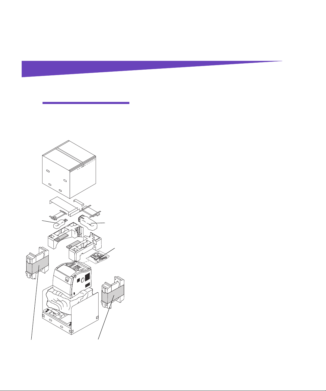
Step 1: Unpack the printer
Caution!
35 kg (77 Ib) and requires at
least two people to lift it.
Coating
roll
This prin t er weighs
Transfer
belt
Manuals,
and CD
1 Remove the coating roll, transfer belt, print car-
tridges, and other accessories from the carton.
Do not remove the print cartridges, transfer belt, or
coating roll from their individual packages until
you are ready to use them.
If any items are missing or damaged, refer to the
registration card for the Lexmark phone number for
your country.
2 Place the carton and packing material aside.
Save the carton and packing materials in case you
need to repack the printer.
3 Make sure you have the items listed below.
– Coating roll
– Tra ns fer bel t
– Setup Guide
– Quick Reference Card
– User’s Guide
– Drivers, MarkVision and Utilities CD
– Power cord
– Printer
– Black, magenta, cyan, and yellow print car-
tridges
Two print cartridges
Two print cartridges
3
Page 8
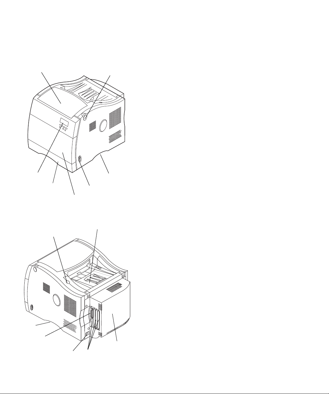
Fuser cover
Identifying
printer parts
Fuser cover
release button
Take a moment to familiarize yourself with the terms, and
location of various items on your new printer. This will
benefit you during the setup of your printer. We will use
the same terms throughout this book and in your User ’s
Guide.
Operator
panel
Paper tray
Multipurpose feeder
(front co ver is locat ed behind feeder)
Cartridge cover release button
Handhold
Parallel connector
Power cord so cket
Power switch
Cartridge cover and output bin
Option ports
Handhold
Rear cover
4
Identifying printer parts
Page 9
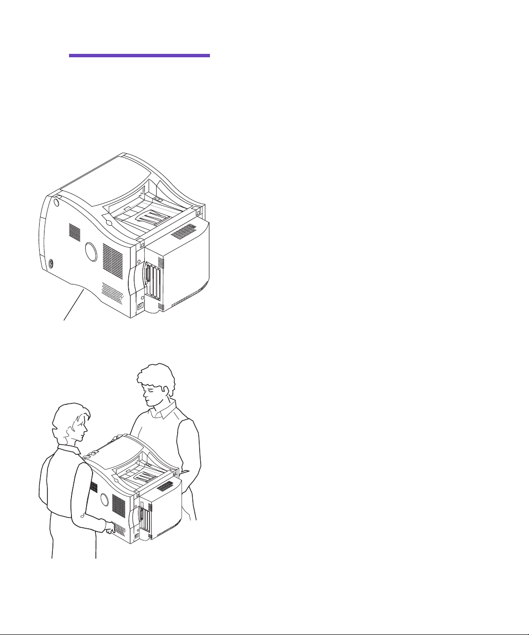
Caution!
35 kg (77 Ib) and requires at
least two people to lift it. Anytime
you move or lift the printer make
sure you have someone help
you.
Handhold (one on each side)
This prin t er weighs
4 Have someone help you lift the printer from the
carton base.
Use the handholds under the printer and support
the front of printer when lifting.
5 Place the printer on a flat, stable surface that will
be convenient for removing the packing material
and installing the components.
Identifying printer parts
5
Page 10
Note:
cartridges, transfer belt, or coating
roll from original packing material
until you are ready to use them.
Do not remove the print
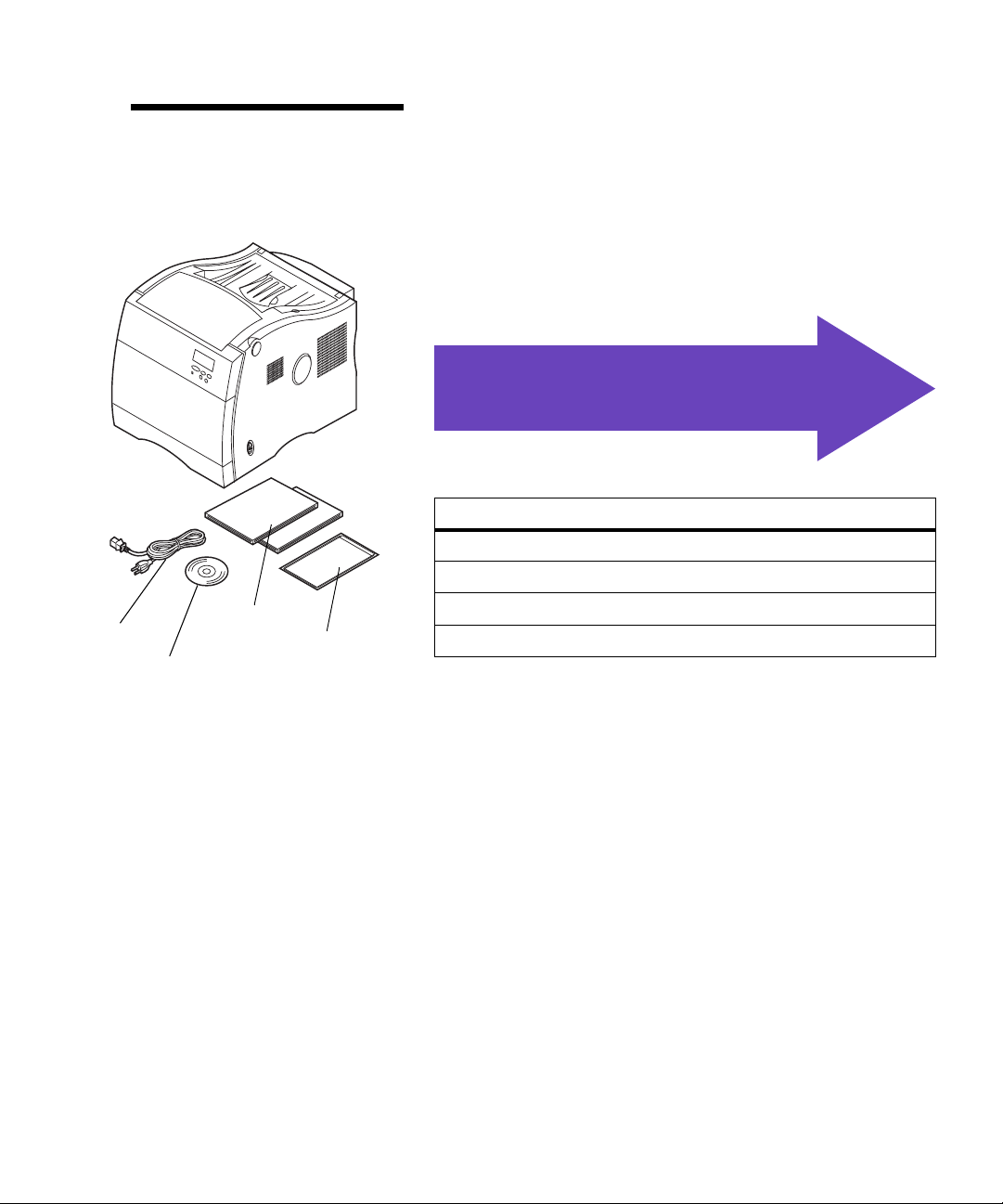
6 Remove the orange tape and other packing
material from the exterior of the printer.
.
Use the table below
to locate your next step
See…
Step 2: “Install memory and network options” on page 7
Step 3: “Set up the optional drawer unit” on page 31
Power cord
6
Manuals
Quick Refe r en c e sleeve
MarkVision CD
Identifying printer parts
Step 4: “Install the optional duplex unit” on page 37
Step 5: “Position the printer” on page 47
Page 11

Step 2: Install memor y and
network options
You can add memory and interface ports to your printer
by installing the following options:
• Printer memory
• Hard disk
• Print server (Internal Network Adapter or INA)
• Tri -p ort ada p te r
• Parallel port adapter
Removing the
rear cover and
EMI shield
Note:
done so, you may want to place
the printer in a convenient location to remove the rear cover,
EMI shield an d in s t all in t e rnal
options.
Caution!
lift the printer make sure you
have someone help you.
Caution!
other devices connected to the
printer, turn them off, unplug
their power cords, and cables
going to the printer.
If you have not already
Anytime you move or
If you have any
You must remove the rear cover and the metal Electromagnetic Interference (EMI) shield to install memory
cards, a hard disk, print server, tri-port adapter, or a parallel port adapter.
You need a number 2 Phillips screwdriver to remove the
rear cover and EMI shield.
1 If you are installing options after initial printer
setup, turn the printer off, disconnect the power
cord, and printer cables.
Removing the rear cover and EMI shield
7
Page 12
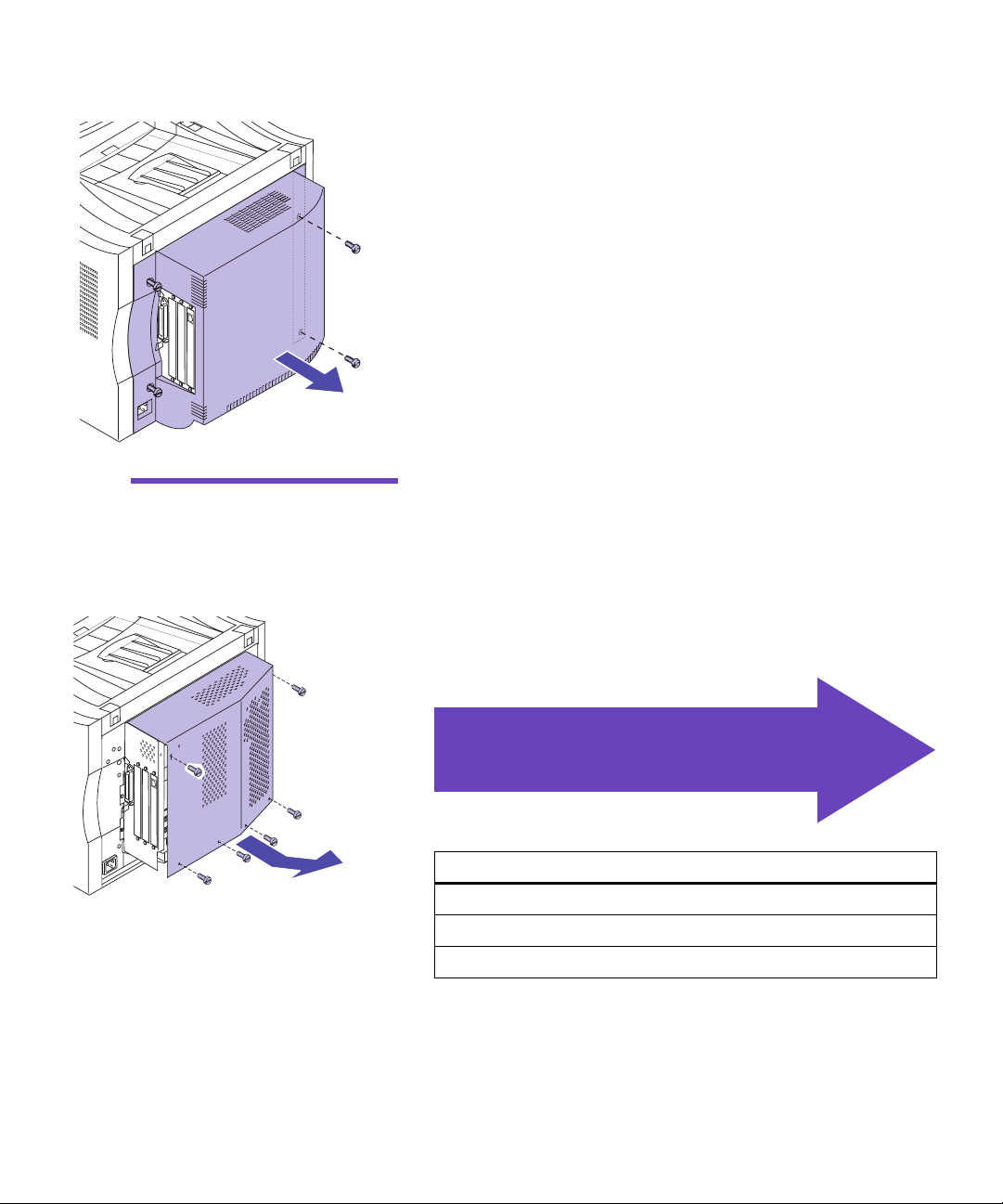
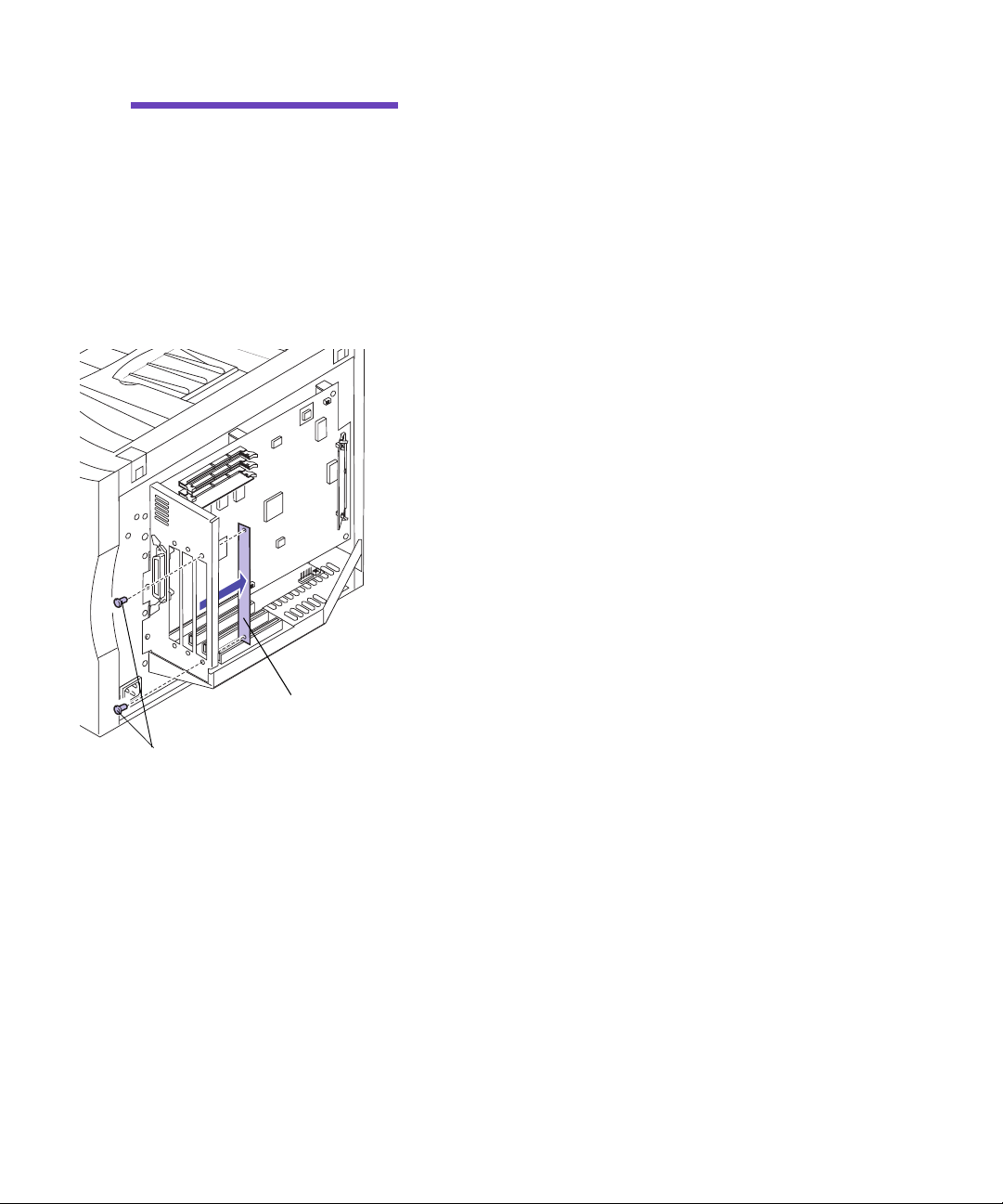
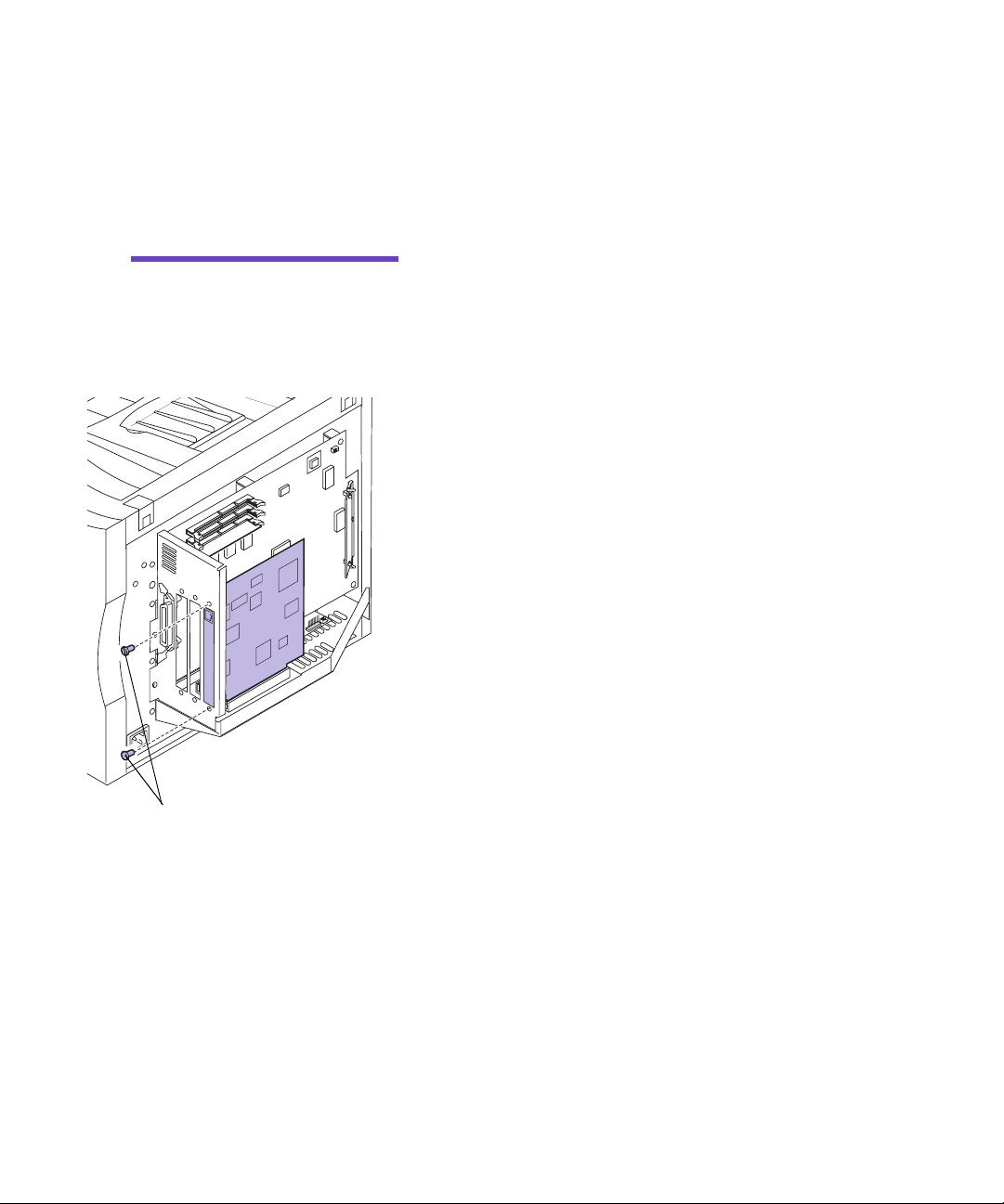
2 Loosen the four screws on the rear cover as shown.
The screws on the rear cover are captive and will
remain on the cover.
3 Remove the rear cover and place it to the side.
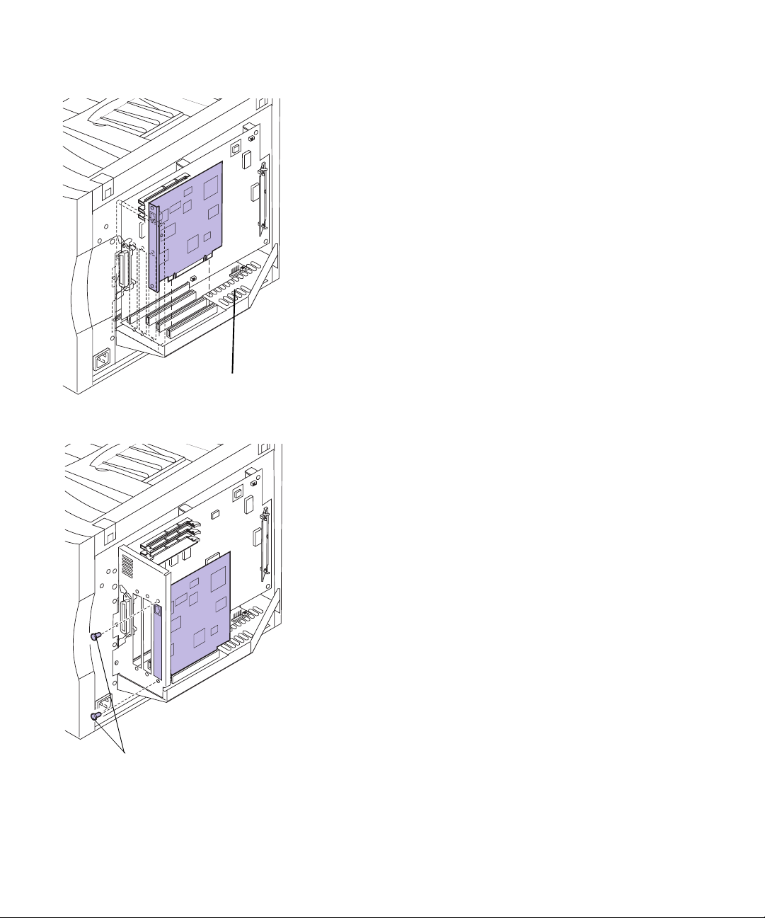
Warning!
be replaced before operating the
printer.
The EMI shield must
4 Loosen the six screws on the EMI shield as shown.
The screws on the EMI shield are captive and will
remain on the shield.
5 Lift and remove the EMI shield and place it to the
side.
Use th e table below to locate
the steps for your options
See…
“Installing memory” on page 9
“Attaching a hard disk” on page 20
“Installing adapters” on page 22
8
Removing the rear cover and EMI shield
Page 13
Installing
memory
Note:
designed for other Lexmark
printers may not work with your
printer. Refe r to the
for more information.
Memory options
User’ s Guide
Memory connectors
Your printer comes with at least 32MB already installed.
(Some printer models may have more standard memory.)
You can purchase many different memory options from
Lexmark for the three memory slots in your printer. The
maximum amount of usable memory is 384MB. Make sure
you use SDRAM DIMM memory cards that meet the following criteria:
– 100 MHz or greater
– 100 pin
– 4K refresh rate
– unbuffered, non ECC
– x32
– 3.3V
If you need to remove a memory card first, see “Removing
a memory card” on page 13.
To install optional memory:
1 Complete the steps “Removing the rear cover and
EMI shield” on page 7 if the rear cover is still
installed.
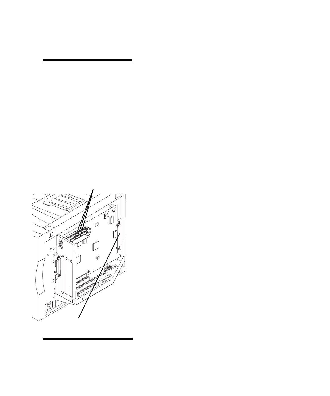
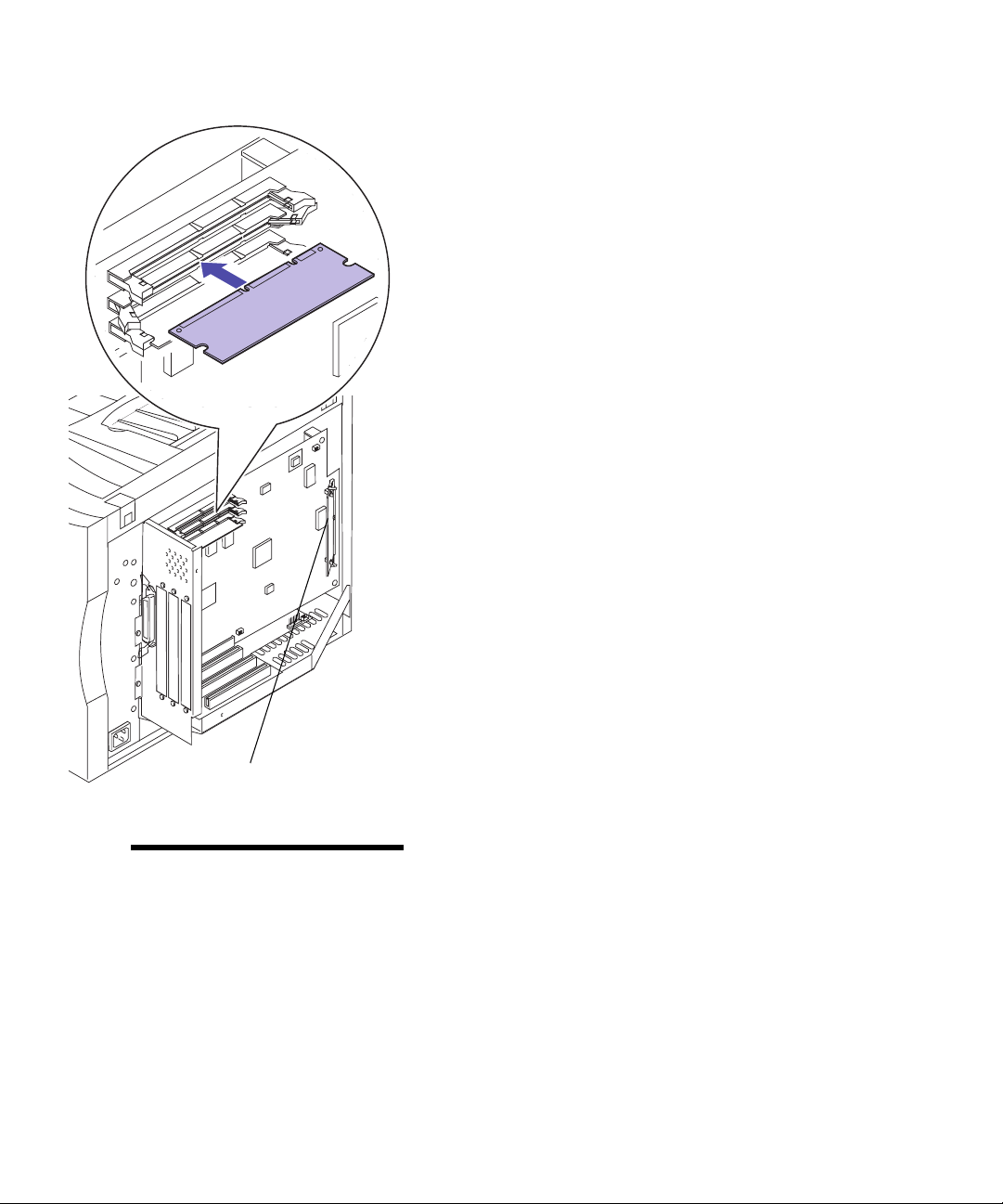
2 Locate the memory connectors on the system
board as shown.
Resident Code Card
DO NOT REMOVE card if present
Note:
have a Resident Code Card.
Your printer may not
Each connector can support either a printer memory
card or a flash memory card.
Installing memory
9
Page 14
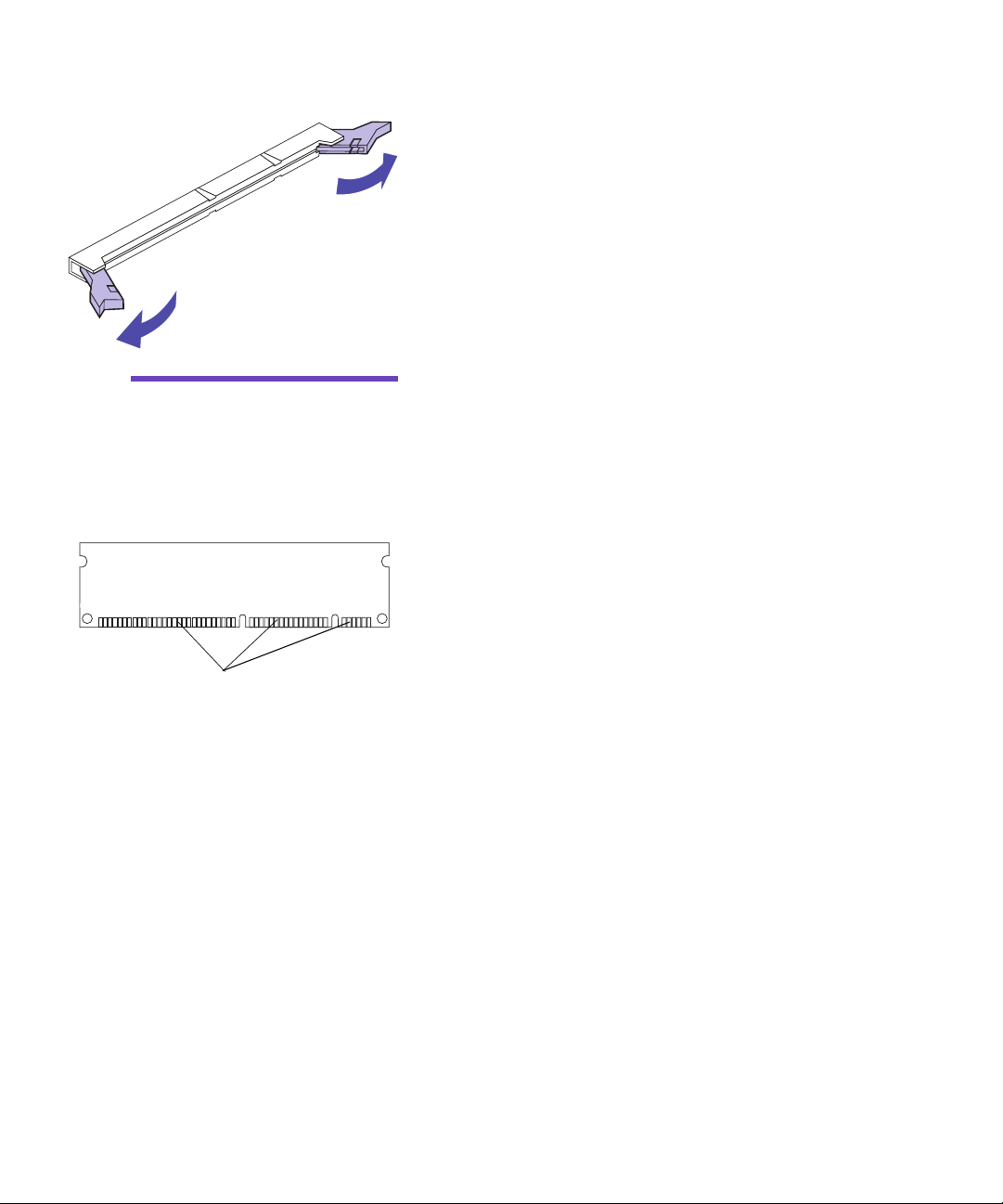
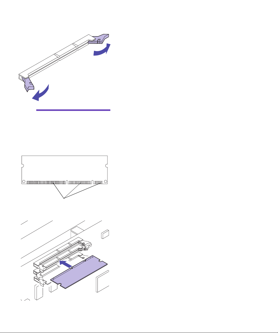
3 Open the latches on both ends of the connector
socket you are going to use.
Warning!
easily damaged by static electricity. Touch something me t al
before you touch the memor y
card.
Connection points
The memory card is
4 Unpack the memory card.
Unpack each memory card separately just before
installing it. Avoid touching connection points
along the edge of card. Save the packaging.
10
Installing memory
Page 15
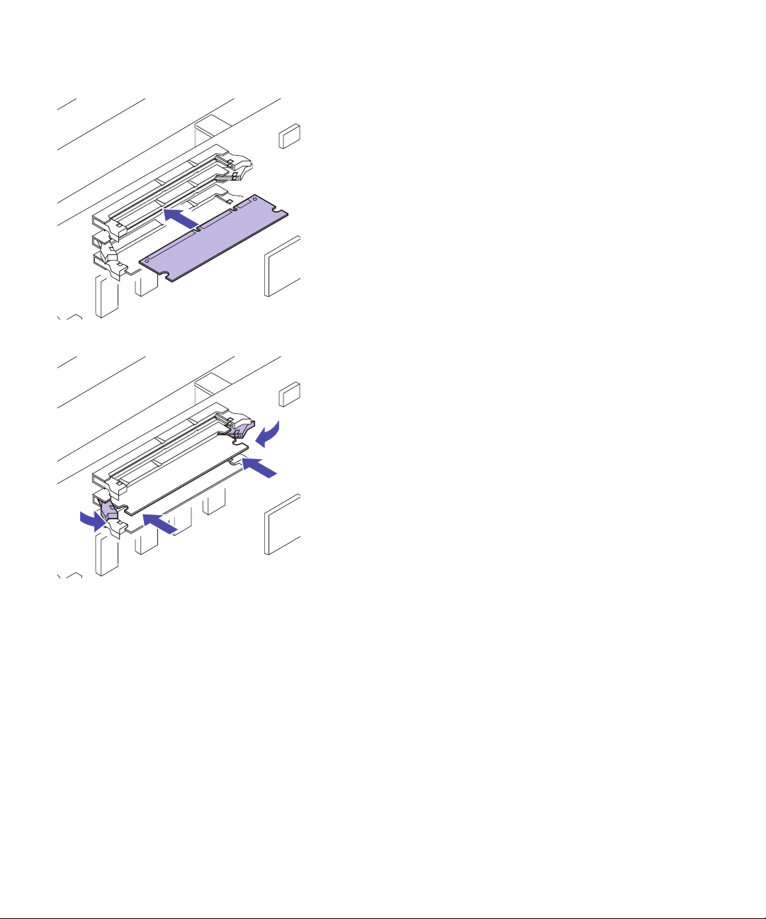
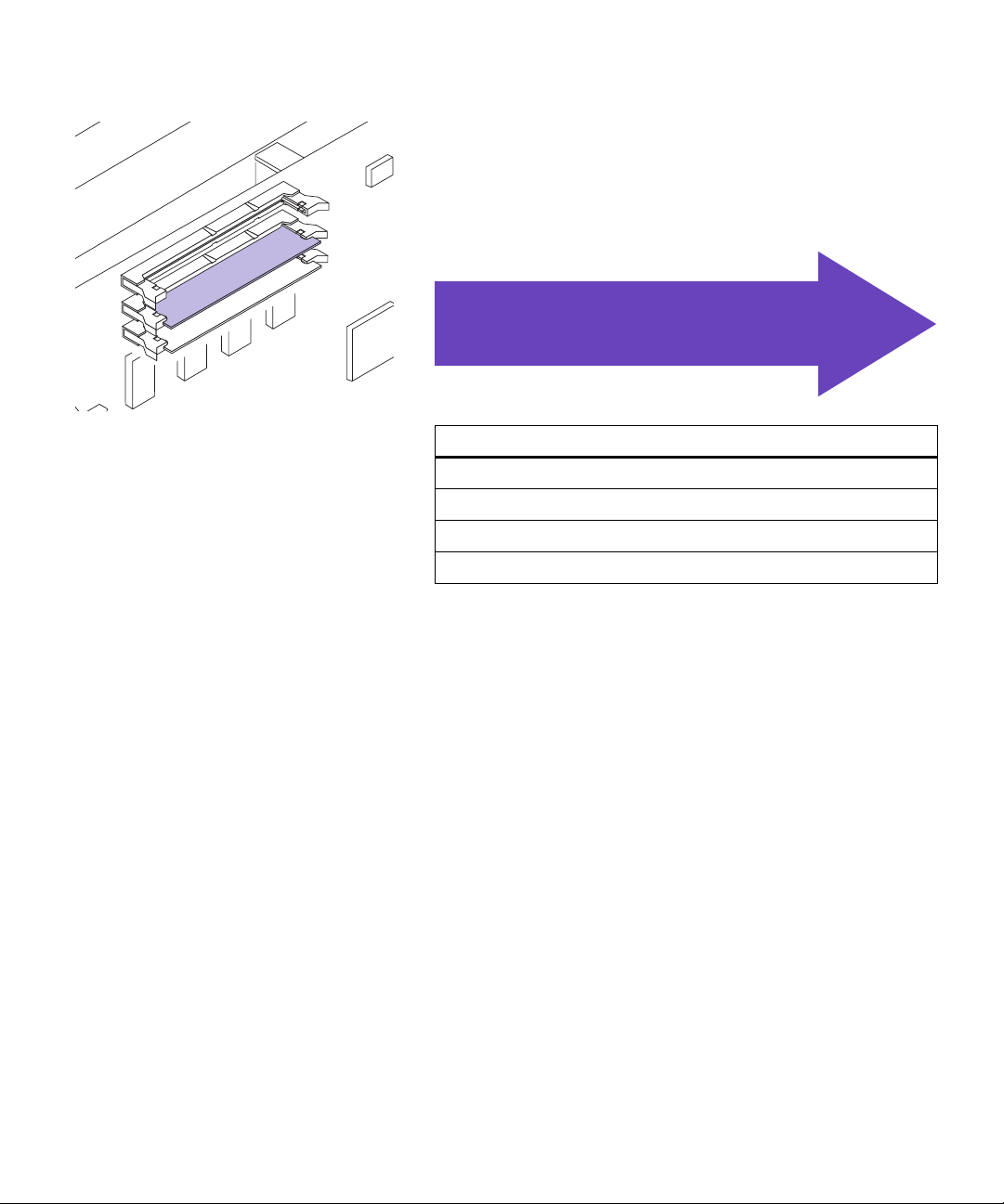
5 Hold the memory card with the connection points
pointing toward the system board as shown.
6 Push the memory card into the connector until the
latches on both ends of the connector snap into
place.
It may require some force to fully seat the card and
have the latches snap into place.
Installing memory
11
Page 16
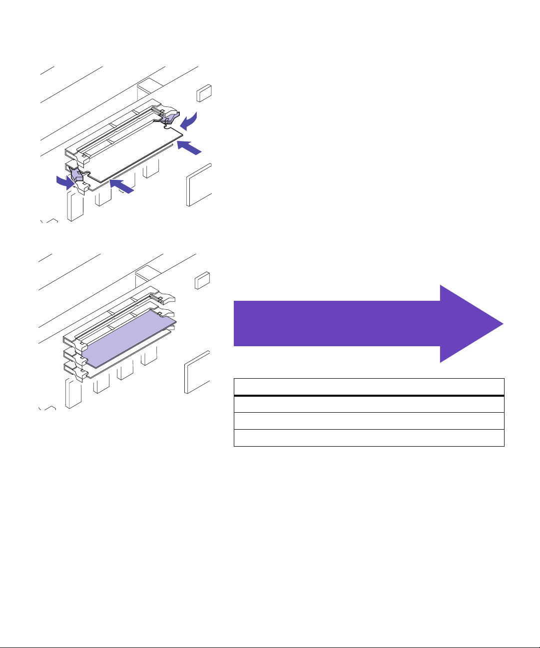
7 Make sure the latches fit over the notches on each
end of the connector card.
8 Repeat steps 3 through 7 to install other memory
cards.
Use th e table below to locate
your next step
Do you need to…
“Install a Flash Memory Card” see page 14
“Attach a hard disk” see page 20
“Install an adapter ” see page 22
“Install the EMI shield and rear cover” see page 28
12
Installing memory
Page 17
Removing a
memory card
Complete the following steps if you need to remove a
memory card. Otherwise, go to “Flash Memory Option”
on page 14, “Attaching a hard disk” on page 20, “Installing adapters” on page 22, or “Installing the EMI shield
and rear cover” on page 28.
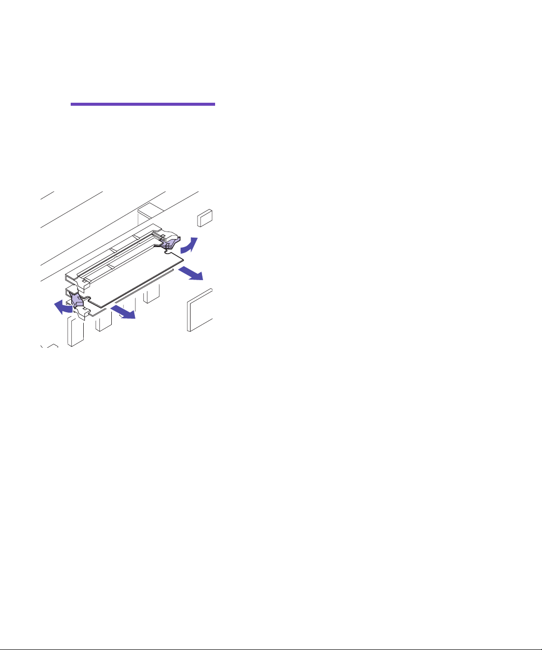
Warning!
easily damaged by static electricity. Touch something me t al
before you touch a memory
card.
Memory cards are
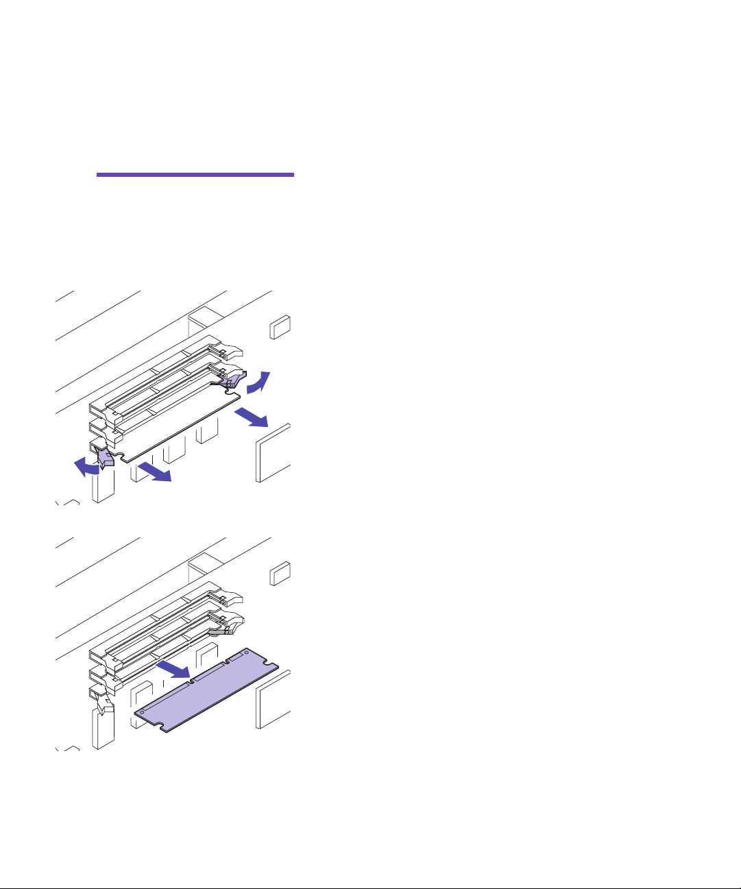
1 Push the latches at each end of the connector away
from the card as shown.
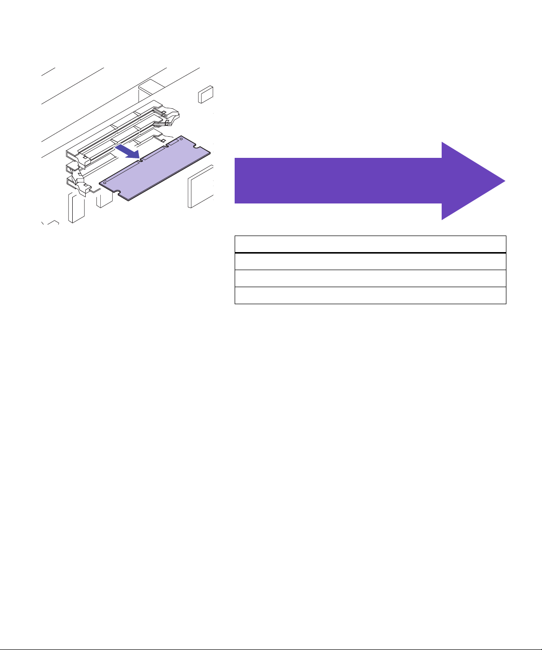
2 Gently pull the card out of the connector.
3 Place the card into the original packaging.
If you do not have the original packaging, wrap the
card in paper and store it in a box.
4 Repeat steps 1 through 3 to remove additional
memory cards.
Removing a memory card
13
Page 18

Flash Memory
Option
Flash memory is useful for storing information such as
downloaded fonts and macros. Your printer driver or
MarkVision can be used to download fonts, symbol sets,
and macros to flash memory.
Information stored in flash memory is retained when the
printer is turned off. You can buy flash memory cards with
2MB, 4MB, 8MB, or 16MB of flash memory.
Refer to the Technical Reference for more details about using
your Flash Memory Option.
Installing a Flash
Memory Card
Note:
support either a printer memo r y
card or a flash memory card.
Installing a flash memory card
reduces your maximum RAM
memory capability.
Each connector can
If you need to remove a flash memory card first, see
“Remove Flash Memory Card” on page 18.
1 Follow the steps for “Removing the rear cover and
EMI shield” on page 7 if the rear cover is still
installed.
14
Flash Mem ory Option
Page 19
2 Locate the memory connectors on the system
board as shown.
Each connector can support either a printer memory
card or a flash memory card.
Resident Code Card
DO NOT REMOVE card if present
Note:
have a Resident Code Card.
Your printer may not
Flash Mem ory O ption
15
Page 20
3 Open the latches on both ends of the connector
socket you are going to use.
Each connector can support either a printer memory
card or flash memory card.
You can not operate the printer with more than one
flash memory card installed.
Warning!
card is easily damaged by static
electricity. Touch something
metal before you touch the
memory card.
Connection points
The flash memory
4 Unpack the flash memory card.
You can install a 2MB, 4MB, 8MB or 16MB flash
memory card.
Unpack the flash memory card just before installing
it. Avoid touching connection points along the edge
of card. Save the packaging.
5 Hold the flash memory card with the connection
points pointing toward the system board as
shown.
16
Flash Mem ory Option
Page 21
6 Push the flash memory card into the connector
until the latches on both ends of the connector
snap into place.
It may require some force to fully seat the card and
have the latches snap into place.
7 Make sure the latches fit over the notches on each
end of the connector card.
Use th e table below to locate
your next step
Do you need to…
“Attach a hard disk” see page 20
“Install an adapter ” see page 22
“Install the EMI shield and rear cover” see page 28
Flash Mem ory O ption
17
Page 22
Remove Flash
Memory Card
1 Follow the steps for “Removing the rear cover and
EMI shield” on page 7 if the rear cover is still
installed.
Warning!
card is easily damaged by static
electricity. Touch something
metal before you touch the
memory card.
The flash memory
2 Push the latches at each end of the connector away
from the card as shown.
18
Flash Mem ory Option
Page 23
3 Gently pull the card out of the connector.
4 Place the card into the original packaging.
If you do not have the original packaging, wrap the
card in paper and store it in a box.
Use the tab le be low
to locate your next step
Do you need to…
“Attach a hard disk” see page 20
“Install an adapter ” see page 22
“Install the EMI shield and rear cover” see page 28
Flash Mem ory O ption
19
Page 24

Hard disk
option c a rd
Two hard disk options are available from Lexmark:
• A Hard Disk already installed on a hard disk
adapter.
• A Hard Disk Adapter for installing a user purchased hard disk.
Warning!
adapter must be installed in
option 3 on the system board.
The hard disk and
Attaching a
hard disk
If you have a hard disk already installed on a hard disk
adapter, continue with “Installing adapters” on page 22.
Otherwise, continue with “Attaching a hard disk”.
Use your adapter card with a third-party hard disk that
meet the following criteria:
– 2.5-inch platter
– ATA-2 (IDE) interface
– Maximum thickness of 13 mm (.51 in.)
– 2.1GB minimum hard disk capacity
– 4GB maximum hard disk capacity
You need a number 2 Phillips screwdriver to attach the
hard disk to the adapter.
To install and attach the hard disk:
1 Align the connector pins on the end of hard disk
with the connector on back of the adapter card.
20
Hard disk option card
Page 25
(Hard Disk is
on this side)
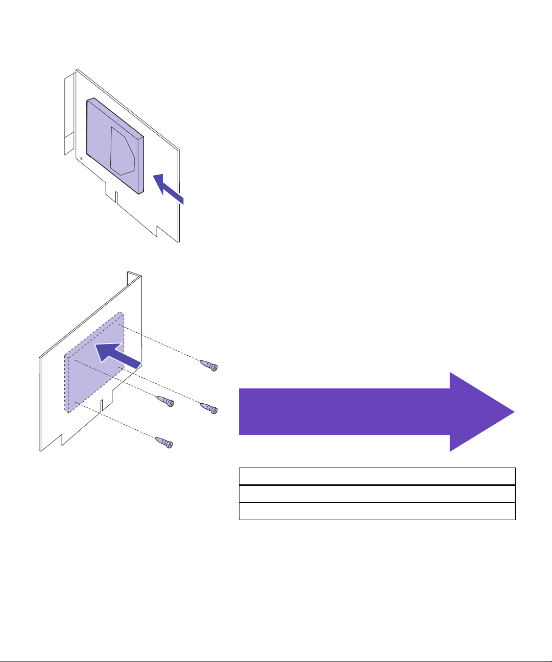
2 Push the hard disk securely into the connector.
3 Turn the adapter card over and insert four screws
through the adapter card.
The illustration shows the outline of the hard disk
on the reverse side of the adapter card.
4 Gently tighten the screws to secure the hard disk
to the adapter card.
Use the tab le be low
to locate your next step
Do you need to…
“Install an adapter ” see page 22
“Install the EMI shield and rear cover” see page 28
Attaching a hard disk
21
Page 26
Installing
adapters
You can install the following adapters in your printer:
• Print server
• Tri -p ort ada p te r
• Parallel port adapter
• Hard disk
• USB adapter
• Fax modem adapter
Note:
printer model, you may already
have a
server
option slots.
Depending on your
MarkNet N2001e print
installed in one of the
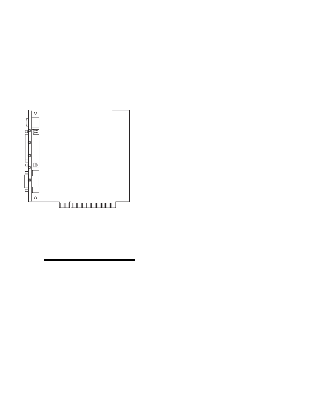
A print server (sometimes called an Internal Network
Adapter or INA), such as the MarkNet
connect the printer to a Local Area Network (LAN). MarkNet N2000 print servers support the following:
• Ethernet 10BaseT and 10Base2
• Ethernet 10/100BaseTX
• Token-Ring
The tri-port adapter provides connectors for the following:
• Serial interface (RS-232C or RS-422), which can also
serve as a receive-only fax port
• LocalTalk network
• An infrared adapter
The parallel port adapter provides an additional
parallel port. Its IEEE 1284C connector requires a
1284 A–C cable. You can purchase a 3 m (9.8 ft) cable, Lexmark part number 43H5171, meeting these specifications.
Refer to the documentation that came with your adapter
for more information.
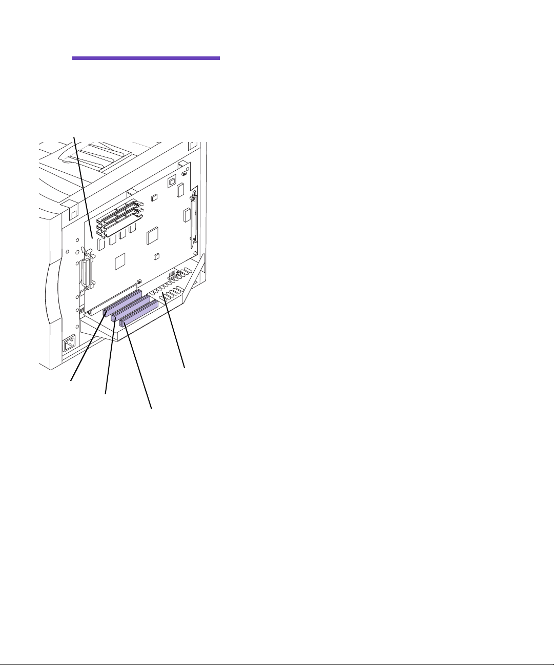
There are three available option slots on your interconnect
board. All option slots support network, tri-port, parallel
port, USB, and Fax modem adapters.
Hard disk adapters must be installed in option 3.
TM
N2001e, lets you
22
Installing adapters
Page 27
Warning!
The hard disk
adapter must be installed in
option 3 on the system board.
Syste m bo ard
You can install any adapter combination in the three
option slots. If you install two tri-port adapters, your
printer can support two serial ports (but only one receiveonly fax port), one LocalTalk port, and one infrared port.
If you are installing one adapter, install it in the open slot
farthest from the printer.
Option 1
Option 2
Interconn e ct board
Option 3
Installing adapters
23
Page 28
Warning!
damaged by static electricity.
Touch something metal before
you touch an adapter.
Adapters are easily
You need a number 2 Phillips screwdriver to install the
adapter.
If you need to remove an adapter first, see “Removing an
adapter” on page 26.
1 Follow the steps for “Removing the rear cover and
EMI shield” on page 7 if the rear cover is still
installed.
2 Before installing an adapter, remove the adapter
cover covering the opening for the option slot you
are going to use.
Remove the screw on each end of the adapter
a
cover.
Save the screws. You will need them to secure the
adapter to the connector bracket.
Remove the plate.
b
Save the adapter cover so you can reinstall it if
you remove the adapter.
3 Unpack the adapter.
24
Save the packing materials.
Adapter cover
Screws
Installing adapters
Page 29
Interconnect board
4 Align the adapter connector with the connector on
the interconnect board.
5 Push the adapter firmly into the connector until it
is seated on the interconnect board.
The two connectors should fit snugly together.
6 Insert the two screws saved from the adapter cover
(or the extra screws shipped with the adapter)
through the holes in the connector bracket and
into the adapter.
Screws
7 Gently tighten the screws to secure the adapter.
8 Repeat steps 2 through 7 to install another adapter.
9 Continue with “Installing the EMI shield and rear
cover” on page 28.
Installing adapters
25
Page 30
Removing an
adapter
You need a number 2 Phillips screwdriver to remove an
adapter.
1 Compete the steps for “Removing the rear cover
and EMI shield” on page 7 if the rear cover is still
installed.
Warning!
damaged by static electricity.
Touch something metal before
you touch an adapter.
Adapters are easily
2 Remove the two screws securing the adapter to the
connector bracket.
26
Screws
Removing an adapter
Page 31

3 Gently pull the adapter completely out of the con-
nector.
4 Place the adapter in its original packaging.
If you do not have the original packaging, wrap the
adapter in paper and store it in a box.
5 If you are not installing another adapter in the
connector, cover the opening with an adapter
cover.
Covering the opening ensures proper airflow
around the system board. If you do not have an
adapter cover, contact your service representative
and request a blank INA cover.
Removing an adapter
27
Page 32

Installing the EMI
shield and rear
cover
Power switch
After you have installed all options on the interconnect
board, complete the following steps to install the rear
cover:
1 Make sure the printer is turned off (O).
28
Installing the EMI shield and rear cover
Page 33

Warning!
be installed before operating the
printer.
The EMI shield must
EMI sh ield
2 Insert the top of the EMI shield into the rear of the
printer.
3 Align the six screws in the EMI shield with the
holes on the printer frame.
4 Tighten the six screws to secure the EMI shield.
Installing the EMI shield and rear cover
29
Page 34

You need a number 2 Phillips screwdriver to install the
cover.
5 Place the rear cover on the printer and align the
screws with the screw holes.
6 Tighten the four screws to secure the rear cover.
If you installed internal options after initial printer
setup, connect the printer cables, power cord, and
turn the printer on.
30
Installing the EMI shield and rear cover
Page 35

Step 3: Set up the optional
drawer unit
Note:
must be installed prior to installing the duplex unit.
Caution!
the optional drawer unit after initial printer setup, turn the printer
off, and disconnect the power
cord and printer cables.
Paper trays
The optional drawer
If you are installing
Option a l drawer un it
Your printer supports an optional drawer unit with two
250-sheet trays. If you are installing the optional drawer
unit, complete the following steps.
1 Remove any orange tape and packing material
from the drawer unit.
Check both trays for packing material.
Set up the optional drawer unit
31
Page 36

864 mm
(34 in.)
203 mm
(8 in.)
203 mm
(8 in.)
532 mm
(21 in.)
228 mm
(9 in.)
1445 mm
(57 in.)
381 mm
(15 in.)
2 Place the drawer unit in the location you have cho-
sen for your printer.
The following guidelines will help to ensure proper
printer operation and prevent print quality problems. They will also extend the life of your printer
and supplies.
Place the drawer unit on a flat, stable surface in a
well–ventilated area.
Leave enough space around the drawer unit for
ventilation and easy access.
Leave space in front of the drawer unit to allow
for easy paper loading. If you plan to install a
duplex unit, leave additional room behind the
drawer unit as well. You will need (507 mm, 20
in.) behind the drawer unit if you plan to install a
duplex option.
Do not place the drawer unit:
– In direct sunlight
– Near heat sources or air conditioners
– In dusty or dirty environments
32
Use the tab le be low
to locate your next step
Do you need to…
“Install the optional duplex unit ”, see page 37
Continue with printer setup, see page 33
Set up the optional drawer unit
Page 37

Caution!
35 kg (77 lb) and requires at
least two people to lift it.
This prin t er weighs
3 Have someone help you lift the printer.
Use the handholds under the printer and support
the front of printer when lifting.
Set up the optional drawer unit
33
Page 38

Note:
and corners of the printer with
the optional drawer unit and then
lower the printer, the pins and
connector will align easier.
If you align the sides
4 Align the pins and connector on top of the
optional drawer unit with the holes and connector
on the bottom of printer.
5 Place the printer on top of the drawer unit.
34
Set up the optional drawer unit
Page 39

6 Insert the optional drawer unit power cord into
the printer power socket as shown.
If you installed the optional drawer unit after initial
printer setup, connect the printer cables, power
cord, and turn the printer on.
Proceed to procedure 3
on page 48
Set up the optional drawer unit
35
Page 40

36
Set up the optional drawer unit
Page 41

Step 4: Install the op tional
duplex unit
Note:
duplex unit is easier if you have
access to the rear and sides of
the printer.
The assembly of the
Installing the
duplex unit base
Caution!
the optional duplex unit after initial printer setup, turn the printer
off, and disconnect the power
cord and printer cables.
If you are installing
For two-sided color or monochrome printing, your printer
supports an optional duplex unit. If you are installing the
duplex unit, complete the following steps.
1 Remove the duplex unit from its packing material.
2 Remove the orange tape and any additional pack-
ing material from the duplex unit components.
Installing the duplex unit base
37
Page 42
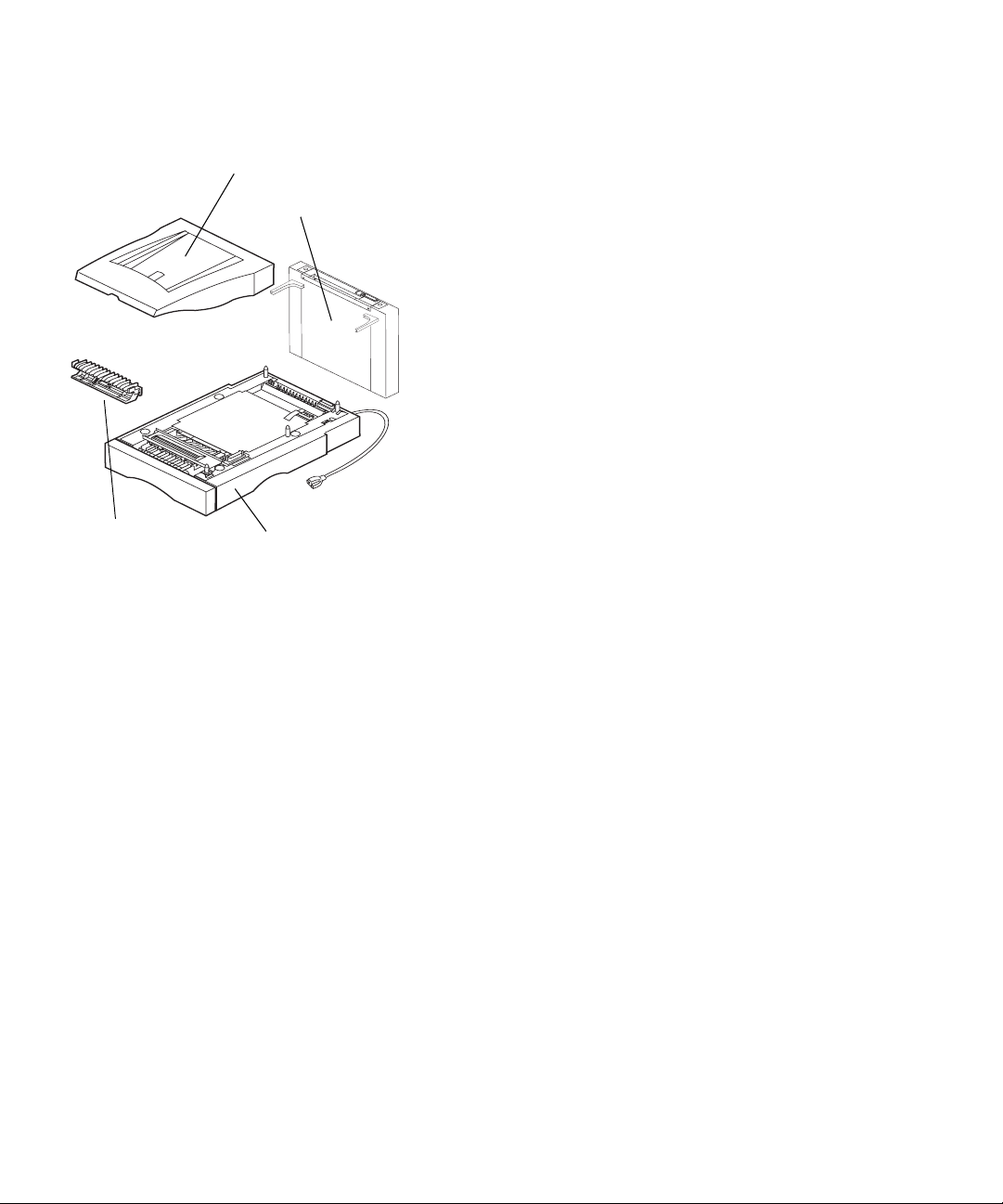
Top duplex assembly
Rear du pl ex assem bly
3 Make sure you have all the items to install the
duplex unit.
If any items are missing or damaged, refer to the
registration card for the Lexmark phone number for
your country.
Save the carton and packing materials in case you
need to repack the duplex unit.
Make sure you have the items listed below:
– Duplex unit base
– Rear duplex assembly
– Top duplex assembly
– Bridge block
Bridge block
Duplex unit ba se
38
Installing the duplex unit base
Page 43

203 mm
(8 in.)
330 mm
(13 in.)
4 Place the duplex unit base in a suitable location.
To mount the duplex unit base on the optional
a
drawer unit, align the pins and connector on
top of the optional drawer unit with the holes
and connector on bottom of the duplex unit
base.
If you do not have an optional drawer unit,
b
place the duplex unit base on a flat, stable surface in a well–ventilated area.
Allow space in front of duplex unit (555 mm, 22
in.) for easy duplex tray removal.
Allow space behind the duplex unit (507 mm, 20
in.) for access to the rear duplex assembly.
The following guidelines will help to ensure proper
printer operation and prevent print quality problems. They will also extend the life of your printer
and supplies.
Do not place the duplex unit:
– In direct sunlight
– Near heat sources or air conditioners
– In dusty or dirty environments
864 mm
(34 in.)
203 mm
(8 in.)
555 mm
(22 in.)
507 mm
(20 in.)
1597 mm
(63 in.)
Installing the duplex unit base
39
Page 44

Caution!
35 kg (77 lb) and requires at
least two people to lift it.
This prin t er weighs
5 Have someone help you lift the printer.
Use the handholds under the printer and support
the front of printer when lifting.
40
Installing the duplex unit base
Page 45

Note:
and front corners of the printer
with the duplex unit base and
then lower the printer, the pins
and connector align easier.
If you align the sides
6 Align the pins and connector on top of the duplex
unit base with the holes and connector on bottom
of the printer.
7 Lower the printer onto the duplex unit base.
Installing the duplex unit base
41
Page 46

Installing the
rear assembly
Alignment pin covers
1 Lift the alignment pin covers from the output bin
on the printer.
Save the alignment pin covers so you can reinstall
them during step 4 on page 43.
42
Installing the rear assembly
Page 47

Note:
access door is at the bottom of
the rear duplex assembly. The
door opens away from the rear
of the printer.
The hinge point of the
Alignment pin
Alignment pin covers
Access doo rRear du pl ex assem bly
Access door
hinge po in t
Alignm e nt pins
2 Align the holes in the support brackets and the
holes on the bottom of the rear duplex assembly
with the pins on the rear of the output bin and the
pins on the duplex unit base.
3 Lower the rear duplex assembly onto the pins and
connector of the duplex unit base until the rear
duplex assembly snaps into place.
4 Place the previously removed alignment pin cov-
ers over the support brackets as shown.
The covers snap into place when aligned and
pressed down.
If the alignment pin covers are difficult to install,
make sure the rear duplex assembly is fully seated
and the brackets are properly aligned on the pins.
Repeat steps 2 and 3 if necessary.
Installing the rear assembly
43
Page 48

Installing the
top assembly
Alignment pins and connector
Pad
1 Place the bridge block onto the forward pad in the
output bin as shown.
The hinged side of the bridge block must be toward
the rear of the printer for correct installation.
The bridge block may be squeezed together to make
placement on the pad easier.
The bridge block has a small magnetic pad on the
bottom that must rest on the metal pad in the front
of the output bin.
2 Align the pins and connector of the top duplex
assembly with the holes and connector on the rear
duplex assembly.
44
3 Lower the pins of the top duplex assembly into the
holes of the rear duplex assembly until the top
duplex assembly snaps into place.
Installing the top assembly
Page 49

4 Lower the top duplex assembly.
5 Insert the duplex unit power cord into the socket
on rear of printer as shown.
Installing the top assembly
45
Page 50

6 Insert the optional drawer unit power cord into
socket on the rear of the duplex unit. If you do not
have an optional drawer unit, insert the power
cord into the duplex unit.
If you installed the duplex unit after initial printer
setup, connect the printer cables and turn the
printer on.
Proceed to procedure 3
on page 48
46
Installing the top assembly
Page 51

Step 5: Position the printer
Caution!
35 kg (77 Ib) and requires at
least two people to lift it.
This prin t er weighs
1 Have someone help you lift the printer.
Use the handholds under the printer and support
the front of printer when lifting.
Position the printer
47
Page 52

203 mm
(8 in.)
203 mm
(8 in.)
532 mm
(21 in.)
786 mm
(31 in.)
381 mm
(15 in.)
2 Place printer on a flat, stable surface in a well–
ventilated area.
Allow space in front of printer for easy tray removal
and paper loading.
The following guidelines will help to ensure proper
printer operation and prevent print quality problems. They will also extend the life of your printer
and supplies.
Do not place the printer:
– In direct sunlight
– Near heat sources or air conditioners
– In dusty or dirty environments
864 mm
(34 in.)
Quick Refe rence sleeve
Note:
holes on the printer.
Do not cover the vent
1445 mm
(57 in.)
3 Find a convenient location for the Quick Refer-
ence card:
Locate a visible spot in the vicinity of the
a
printer or on the printer for the Quick Reference sleeve.
Remove the protective paper from the back of
b
the plastic sleeve.
Firmly attach the adhesive-backed sleeve to the
c
designated area.
48
Position the printer
Page 53

Step 6: Install the t ransfer belt
Your printer ships with a transfer belt that must be
installed for your printer to operate. The transfer belt carries an image from the print cartridge to the paper.
Complete the following steps to install the transfer belt.
1 Make sure the printer is turned off (O).
2 Make sure the power cord from the outlet to the
printer or optional device is unplugged.
Power switc h
Install the transfer belt
49
Page 54

Multipurpose
feeder
3 Open the multipurpose feeder.
4 Lift the front cover latch.
Front cover latch
5 Open the front cover.
6 Remove any orange tape or packing material from
inside the front of the printer.
50
Install the transfer belt
Page 55

Warning!
the transfer belt on its end. Do
not touch the glossy transfer
film. Touching the film may
cause print quality problems.
Do not tilt or rotate
7 Remove the transfer belt from its package.
8 Remove the orange tabs and any packing material
or tape from the transfer belt.
Lift and pull the orange tab trom the top of the
a
transfer belt.
Pull the two bottom orange tabs away from the
b
transfer belt.
9 Align the bottom of the transfer belt with the rails
inside the printer.
10 Push the transfer belt into the printer until it is
firmly seated.
Install the transfer belt
51
Page 56

11 Close the front cover.
12 Close the multipurpose feeder.
52
Install the transfer belt
Page 57

Step 7: Instal l the coating roll
Your printer ships with a coating roll that must be
installed for your printer to operate. The coating roll lubricates the fuser with oil and must be placed inside the
fuser.
Complete the following steps to install the coating roll.
1 Make sure the printer is turned off (O).
2 Make sure the power cord from the outlet to the
printer or optional device is unplugged.
Power switch
Install the coating roll
53
Page 58

Note:
installed, lift the duplex top cover
first.
If the duplex unit is
Fuser cover
release button
3 Press the fuser cover release button and lift the
fuser cover.
Fuser door
54
4 Lift the fuser door.
Install the coating roll
Page 59

5 Remove the orange tabs and any packing material
from the fuser compartment.
Rotate the tabs toward each other as shown.
a
Pull the tabs up to remove them from the fuser.
b
Coating roll
6 Remove the coating roll from its package.
7 Remove the orange tape and packing material
from the coating roll.
Make sure all of the plastic wrapping is removed
from the coating roll.
Install the coating roll
55
Page 60

8 Align the bar on the side of the coating roll with
the slots in the fuser.
9 Lower the coating roll into the fuser.
10 Close the fuser door.
56
Install the coating roll
Page 61

11 Close the fuser cover.
Install the coating roll
57
Page 62

58
Install the coating roll
Page 63

Step 8: Install the
print cartridges
Your printer ships with four color-coded print cartridges.
These cartridges must be placed on the carousel inside the
printer. Each cartridge has its own color-coded position on
the carousel.
Complete the following steps to install the four print cartridges. A message on the operator panel indicates which
print cartridge to install.
1 Make sure the printer is turned off (O).
Power switch
Install the print cartridges
59
Page 64

Caution!
optional duplex unit or optional
drawer unit, ensure the power
cord from the appropriate
optional device is connected to
the rear of the printer before
plugging the power cord into a
properly grounded electrical outlet.
Cartridge cover
If you have an
2 Plug the end of the power cord onto the connector
on the back of printer or the appropriate optional
device.
Power swi tch
60
Warning!
tridge cover when the carousel
is rotatin g .
Install the print c art ridges
Do not open the car-
3 Place the printer power switch in the on (I) posi-
tion.
After you turn the printer on, it performs a self test.
During this period it detects the missing print cartridges.
Page 65

Note:
plays “Open Top Door”. This
instructs you to open the cartridge cover.
30
Color
The operator panel dis-
Toner
Cart Missing
4 View the operator panel and determine which car-
tridge must be installed.
1 Menu 2
Warning!
tridge cover when the carousel
is rotatin g .
Car t r i dg e cover
Select 3
Go 5
Do not open the car-
Return 4
Stop 6
5 Press the cartridge cover release button.
6 Lift the cartridge cover.
Cartridge cover release button
Install the print cartridges
61
Page 66

Warning!
insert the print cartridge using
the handle only . To prevent damage to the print cartridge, do not
handle the shutter covering the
photocondutor.
Photoconductor shutter
Lift, shake, and
Print cartridge handle
7 Remove the appropriate print cartridge from the
packing material.
Your print cartridge has a shutter to protect the photoconductor. Do not move the shutter or touch the
photoconductor (glossy green surface under the
shutter), it may become scratched or damaged.
Do not leave the cartridge cover open longer than
necessary. If you expose the photoconductor to light
for more than 10 minutes it may become damaged.
Cover the cartridge if it will be exposed to light for
more than 10 minutes.
8 Remove the orange tabs and any packing material
or tape from the print cartridge.
There are two orange tabs, one on each side of
the print cartridge.
Pull the orange tabs away from the print cartridge to remove them.
62
9 Gently shake the print cartridge to distribute the
toner evenly.
Install the print c art ridges
Page 67

Note:
and color coded to fit a specific
location on the carousel. If the
cartridge does not fit, ensure
the cartridge is being placed in
the correct location.
Photoconductor shutter
Each cartridge is keyed
Print cartridge handle
10 Angle the print cartridge and place it on the carou-
sel.
The cartridge is installed with the photoconductor
shutter towards the front of the printer. To align and
insert the cartridge, the edge of the cartridge toward
the rear of the printer must be angled downward.
11 Make sure the cartridge is lying flush on the car-
ousel.
12 Press the print cartridge handle to flatten the han-
dle against the print cartridge.
Install the print cartridges
63
Page 68

Note:
closed for the carousel to rotate
to the next em pty position. If you
have a duplex unit installed you
must close both the duplex unit
and cartr idge covers for the carousel to rotate.
The cover must be
13 Close the cartridge cover.
After you close the cover, the printer searches for
another missing cartridge. The operator panel displays which color must be installed if another cartridge is missing.
Repeat steps 4 through 13 to install another cartridge.
14 Place the printer power switch in the off (O) posi-
tion.
64
Power switch
Install the print c art ridges
Page 69

Step 9: Attach the cables
Cable information
You can attach the printer to a LAN by:
• Connecting the printer directly to the server using a
parallel or serial cable.
Your printer’s standard parallel port requires an
IEEE-1284 compliant parallel cable. We recommend
Lexmark part number 1329605 (10 ft) or 1427498
(20 ft). If you installed an optional parallel port
adapter, you need a 3 m (9.8 ft) 1284 A–C parallel
cable, such as Lexmark part number 43H5171. If
you use something other than an IEEE-compliant
cable, you may not be able to access all of your
printer ’s functions.
If you’re attaching a serial cable, we recommend
Lexmark part number 1038693 (50 ft). Attach the
cable to the serial connector on the optional tri-port
adapter you installed in the printer.
• Connecting the printer directly to the LAN:
– Use an External Network Adapter (ENA), such
as Lexmark’s MarkNet Pro
– Use a print server, such as the MarkNet N2000
series described on page 22
– Use the optional tri-port adapter to connect to a
LocalTalk network
For more information about your particular adapter,
refer to the documentation that came with the
adapter.
Cable information
65
Page 70

Note:
work cable even if the internal
print server (sometimes called
internal network adapter) has
more than one network por t.
Connect only one net-
To attach a cable to your printer:
1 Make sure the printer power is off (O) and the
power cord is unplugged.
Caution!
cable to the printer from another
powered component make sure
you unplug that component
before connecting any cables to
the printer.
Standard parallel
cable and co nn ec tor
When connecting a
2 At the left rear of printer, locate the parallel, serial,
or network cable connector.
One parallel connector is standard. Depending on
the options you have installed, additional parallel,
serial and network connectors may be available.
3 Connect the appropriate cable.
Use the tab le be low
to locate your next step
Do you need to…
“Connect an external fax modem”, see page67
“Connect an infrared adapter”, see page 70
“Continue with printer setup”, see step 4
66
Optional cable and
connector
Note:
fax modem or infrared adapter,
do not connect the power cord
or turn on the printer at this
time.
Cable information
If you are installing a
4 Plug the power cord into a properly grounded
electrical outlet.
5 Place the printer power switch to on (I).
Proceed to Step 10: “Load the
paper tray” on page 73
Page 71

Power cord
Connecting an
external
fax modem
To printer
serial port
Modem
cable
If you installed an optional tri-port adapter in your
printer, you can attach an external, class 1 fax modem to
the serial port on the adapter. You can then use your
printer to receive faxes.
Faxes received print in black only. You cannot send faxes
from your printer.
To set up the serial port to receive faxes:
1 Make sure the printer power is off (O) and the
power cord is unplugged.
2 Place the modem power switch to off (O).
3 Follow the instructions included with the modem
to connect the modem to the serial port.
The modem connects to the printer in the same way
it would connect to a computer. Make sure the
modem cable has a 25-pin connector to attach to the
serial connector on the printer.
External
class 1 fax
modem
Phone c ord
4 Plug the modem power cord into a properly
grounded electrical outlet.
5 Place the modem power switch to on (I).
You must turn the modem on before you turn on the
printer.
6 Plug the printer power cord into a properly
grounded electrical outlet.
7 Place the printer power switch to on (I).
8 From the printer operator panel:
Press the
a
menus.
Menu>
or
<Menu
button to enter the
Connecting an external fax modem
67
Page 72

FAX MENU
Continue to press
b
FAX MENU
the
Press the
c
Select
.
button.
Menu>
or
<Menu
until you see
Fax Port
1 Menu 2
Note:
figure the serial port for multiple
uses with an A-B switch.
Select 3
Go 5
Do not attempt to con-
Stop 6
Return 4
Fax Port
Press the
d
Press
e
appears on the second line of the display.
Select
button.
Menu>
or
<Menu
until the serial port you
want to set up as a fax port appears on the second line of the display.
For example, if you installed a tri-port adapter in
connector 2,
Press the
f
look for
Select
Ser Option 2
button.
.
The printer resets. You are now ready to receive
faxes.
Refer to the printer User’s Guide for information about
changing the fax communication settings, such as baud
and parity.
To disable the fax modem and restore the printer serial
port to normal use:
1 From the printer operator panel:
Press the
a
menus.
Menu>
or
<Menu
button to enter the
68
Connecting an external fax modem
Continue to press
b
FAX MENU
Press the
c
Fax Port
Press the
d
Press
e
displayed.
Select
appears on the second line of the display.
Select
Menu>
or
Menu>
button.
button.
<Menu
until
<Menu
or
Disabled
until you see
appears on
the second line of the display.
Press the
f
Select button to reset the printer
2 Place the modem power switch to off (O).
.
Page 73

3 Place the printer power switch to off (O).
4 Unplug the printer power cord from the electrical
outlet.
5 Unplug the modem power cord from the electrical
outlet.
6 Disconnect the modem cable from the printer
serial port.
7 Plug the end of the printer power cord into a prop-
erly grounded electrical outlet.
8 Place the printer power switch to on (I).
Use the tab le be low
to locate your next step
Do you need to…
“Connect an infrared adapter”, see page 70
“Load the paper tray”, see page 73
Connecting an external fax modem
69
Page 74

Connect infrared
adapter
You can use an infrared adapter to print remotely from a
computer equipped with an infrared port.
The optional tri-port adapter, which includes an infrared
port, lets you connect the infrared adapter to your printer.
After you have installed the tri-port adapter, complete the
following steps to connect the infrared adapter to your
printer:
1 Make sure the printer power is off (O).
2 Unplug the printer power cord from the electrical
outlet.
3 Locate the infrared port at the left rear of printer.
The infrared port is attached to the tri-port adapter
you installed earlier.
4 Plug the adapter cable into the infrared port.
5 Plug the printer power cord into a properly
grounded electrical outlet.
6 Place the printer power switch to on (I).
70
Adapter cable
Connect infrared adapter
If the light on the infrared adapter comes on when
the printer power is on, the adapter is plugged into
the printer port correctly.
Page 75

7 Draw an imaginary line between the infrared port
on the computer and the infrared port on the front
of the adapter.
Refer to the documentation that came with your
computer for information about your computer ’s
infrared port.
8 Aim the infrared port on your computer within
15 degrees of either side of this line.
Connect infrared adapter
71
Page 76

72
Connect infrared adapter
Page 77

Step 10: Load the paper tray
Loading the
paper trays
Note:
the duplex unit tray.
Note:
cies in tray 1, make sure you
change the Paper Type setting to
transparency. See “Changing
the Paper Type setting” on
page 81 for more information.
Do not place paper into
If you load transparen-
Your printer has one standard 250-sheet tray—tray 1—
that holds A4, B5, letter, legal, and executive size paper.
You can also load transparencies in tray 1 or the multipurpose feeder. For details about the types of media your
printer supports, refer to your printer User’s Guide.
If you attached an optional drawer unit, the instructions
are the same for loading paper in those trays. However,
load only paper in tray 2 and tray 3.
To load the tray:
1 Pull the paper tray completely out of the printer.
2 Set the paper tray on a flat surface.
Loading the paper trays
73
Page 78
Note:
or letter size paper, the tray
may already be set up for the
appropriate paper size.
If you are loading A4
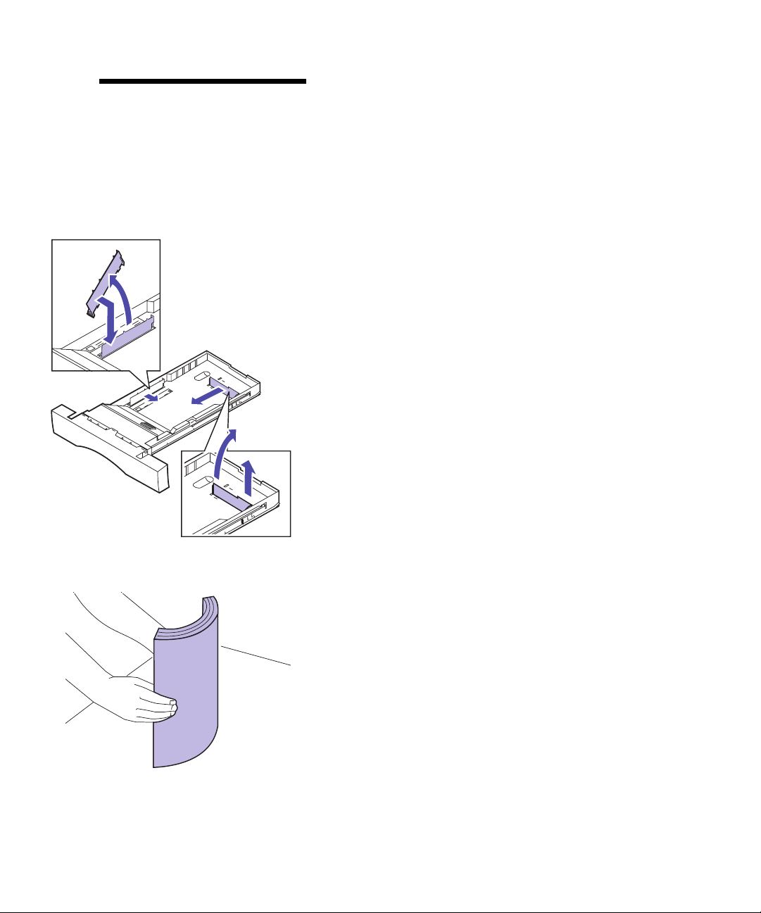
3 Squeeze the snap lock on the end of the rear paper
guide.
4 Lift the rear paper guide from the tray.
5 Align the rear paper guide with the position for
the paper size you are loading.
The position of the rear paper guide tells the printer
the size of the paper in the tray. If the rear paper
guide is in the wrong position, you may experience
paper feeding problems or incorrect formatting of
pages.
6 Set the rear paper guide into the holes on the side
and bottom of the paper tray.
7 Squeeze the snap lock on the end of the side paper
guide.
8 Lift the side paper guide from the paper tray.
9 Align the side paper guide with the position for
the paper size you are loading.
74
10 Set the side paper guide into the holes on the side
and bottom of the paper tray.
11 Before loading the paper, flex the sheets back and
forth to loosen them, and then fan them.
Straighten the edges on a level surface.
Loading the paper trays
Page 79

12 Load the paper with the recommended print side
face up.
Do not exceed the maximum stack height indicated
on the paper guide.
Place the short edge of the paper at the front of the
tray.
If you’re loading preprinted letterhead, place the
top of the page at the front of the tray with the letter
head up.
Short edge
Maximum stack height
13 Slide the paper tray into the printer.
Loading the paper trays
75
Page 80

Load
multipurpose
feeder
You can load up to 50 sheets of paper, 30 transparencies, 30
sheets of labels, or 9 envelopes in the multipurpose feeder.
You can also use the multipurpose feeder for manually
feeding single sheets of media. Refer to your User’s Guide
for more details about printing transparencies, envelopes,
labels and card stock through the multipurpose feeder.
To load paper in the multipurpose feeder:
Note:
purpose feeder while paper or
envelopes are in the feeder.
Do not close the multi-
1 Pull the front of the multipurpose feeder down.
2 Before loading the media, flex the sheets back and
forth to loosen them, and then fan them.
Straighten the edges on a level surface.
76
Load multipurpose feeder
Page 81

3 Load the media face down and slide the paper
guide to the right until it touches the media.
If you are loading preprinted letterhead, place the
top of the page toward the printer face down.
4 Set the paper type for the type media you are
using.
You can set the paper type through the paper menu
on the operator panel or your printer driver. For
more information on setting the paper type, see
“Changing the Paper Type setting” on page 81.
Pape r g uid e
Note:
clarity.
Paper removed f or
Load multipurpose feeder
77
Page 82

Loading
envel opes
Note:
in the paper trays. Envelopes
can only be fed through the multipurpose feeder.
Do not load envelopes
1 Place the envelopes on the multipurpose feeder
with the flap up and on the right side of the
printer. Make sure the short edge of the envelope
enters the printer as shown.
Do not load envelopes that have been prestamped
by the post office.
Do not load envelopes with stamps affixed.
Do not load envelopes that contain windows, holes,
perforations, cutouts, or embossing
Do not close the multipurpose feeder while envelopes are in the feeder.
Refer to your User’s Guide for more information on
using envelopes.
2 Set the paper source to
You can set the paper source through the
MENU
on the operator panel or your printer driver.
MP Envel ope
.
PAPER
78
Loading envelopes
3 Set the envelope size to match your envelope.
You can use your operator panel or printer driver to
select the appropriate envelope size through the
Manual Env Size
PAPER SIZE
and
settings listed under
.
PAPER MENU
Page 83

Step 11: Verify setup
This section of the setup guide will help you verify your
printer is installed and operating correctly. You will print a
settings page you can review to identify all of your
installed options. The settings page also indicates if they
are operating correctly.
1 Make sure the printer is on (I).
After you turn the printer on, it performs a self test
and warms up. During this period, the messages
Performing Self Test
the operator panel display.
Power switch
The self test and warming of the printer ensures all
components function and the printer is at the correct operating temperature for proper operation.
If you receive an error code on the operator panel
display such as
to the troubleshooting section of the User’s Guide.
and
Error 202
Warming Engine
(coating roll missing) refer
appear on
After the printer completes its internal tests and
Ready
warms, the
status message is displayed.
Verify setup
79
Page 84

Ready
If Power Saver is set On (the factory default),
Power Saver
replaces the
Ready
status message after
the specified period of time. Both messages indicate
the printer is ready to receive print jobs. Refer to the
User’s Guide for more information about modifying
the Power Saver setting.
1 Menu 2
Select 3
Go 5
Printing the menu
settings
UTILIT IES MENU
Return 4
Stop 6
If an error message is displayed, refer to the User’s
Guide for helpful tips.
Print the menu settings page to review the default printer
settings and to verify the printer options are installed correctly. For more information about using the printer operator panel and changing menu settings, refer to the User’s
Guide.
Complete the following steps to print the menu settings
page.
or
Menu>
<Menu
or
until
1 From the printer operator panel, press the
<Menu
button to enter the operator panel menus.
2 Continue to press and release
you see
UTILITIES MENU
Menu>
displayed on the operator
panel.
Print Menus
1 Menu 2
80
Printing the menu settings
Select 3
Go 5
Return 4
Stop 6
3 Press the
UTILITIES MENU
Print Menus
and
Select
button.
is then displayed on the first line,
is on the second line
.
Page 85

Note:
menu settings page, ensure the
selected paper source holds A4
or letter size paper. If you use
different size paper or different
paper type, you need to set the
printer to the correct size and
type. Refer to the
for more information on paper
sizes and source s.
Before printing the
User’s Guide
4 Press the
tings page.
The message
printer will return to
settings page prints.
If an error message appears on the display, refer to
the User’s Guide for more information.
Select
button again to print the menu set-
Printing Menu Sett ings
Ready
status after the menu
is displayed. The
5 Verify the options you installed are listed on the
menu settings page under “Installed Features.”
If an option you installed does not appear on the
page, turn the printer off, unplug the power cord,
and reinstall the option.
6 If you attached a serial cable, verify the printer
serial settings listed on the menu settings page are
appropriate for your system.
Refer to the User’s Guide for more information about
the Serial Menu and changing these settings.
Changing the
Paper Type
setting
It is important to verify the Paper Type settings are accurate for all the installed paper sources. Refer to the menu
settings page you printed. The Paper Type is listed for
each of the installed paper sources.
Paper Type refers to the type of media loaded in the
sources: plain paper, letterhead, envelopes, and transparencies. Since different sources can hold different media,
you can customize the Paper Type settings for each source.
The printer uses the Paper Type setting to optimize print
quality for the media you specified. For example, selecting
the Transparency paper type causes the printer to heat the
fuser to a higher temperature and slows printing to produce the best transparency possible.
The Paper Type setting also affects the printer’s automatic
source selection capability, as well as the tray linking function. For these reasons, it’s important to change the setting
each time you change the media in the tray or feeder.
Changing the Paper Type setting
81
Page 86

Refer to the User’s Guide for more detailed information
about the paper types supported by each paper source, as
well as ways to use the Paper Type setting to make printing more efficient in your work environment.
If you need to change a Paper Type setting:
PAPER MENU
PAPER TYPE
1 Menu 2
Select 3
Go 5
PAPER TYPE
Tray1 Type
1 Menu 2
Select 3
Return 4
Stop 6
Return 4
1 From the printer operator panel, press the
<Menu
button to enter the menus.
PAPER MENU
play.
2 Press the
3 Press and release
on the second line
4 Press the
Tray 1 Type
5 Press the
Tray 1 Type setting.
6 Press
Menu>
sible paper types for tray 1.
appears on the second line of the dis-
Select
button to open the Paper Menu.
Menu>
.
Select
button.
appears on the second line of the display.
Select
again if you want to change the
<Menu
or
to scroll through a list of pos-
until
PAPER TYPE
Menu>
or
appears
7 When the correct paper type appears on the second
Select
line of the display, press the
save the type as the default for tray 1.
button again to
8 If you need to change the Paper Type setting for
Menu>
another source, press
priate source, and then repeat steps 5 through 7.
to scroll to the appro-
82
Go 5
Changing the Paper Type setting
Stop 6
9 When you are finished changing the Paper Type
Go
settings, press the
to the ready state.
button to return the printer
Page 87

Printing an
adapter setup
page
If you installed a network adapter and want detailed
information about the option and the active protocols,
complete the following instructions to print the adapter
setup page:
Note:
mation during network setup.
You will need this infor-
NETWORK MENU
NETWORK OPTION 1
1 Menu 2
Select 3
Go 5
Return 4
Stop 6
NETWORK OPTION 1
NETWORK 1 SETUP
1 From the operator panel, press
enter the menus.
2 Continue to press and release
you see
panel
3 Press the
NETWORK OPTION 1
the display. If necessary, press
display the correct network option.
4 Press the
5 Press
SETUP
NETWORK MENU
.
Select
button.
Select
button.
Menu>
on the second line of the display.
or
<Menu
displayed on the operator
appears on the second line of
until you see
Menu>
Menu>
Menu>
<Menu
or
<Menu
or
or
NETWORK 1
<Menu
until
to
to
1 Menu 2 Select 3
Go 5
Return 4
Stop 6
Printing an adapter setup page
83
Page 88

6 Press the
Select
button.
NETWORK 1 SETUP
Print
1 Menu 2
Select 3
Go 5
Return 4
Stop 6
Print
Print Setup Page
1 Menu 2
Select 3
Return 4
7 Press
Menu>
ond line of the display.
8 Press the
Print Setup Pa ge
display.
9 Press the
<Menu
or
Select
Select
until you see
button.
appears on the second line of the
button to print the page.
Print
on the sec-
84
Go 5
Printing an adapter setup page
Stop 6
Page 89

Step 12: Load MarkVisio n and
drivers
Load drivers
The Compact Disc (CD) shipped with your printer contains the printer drivers and utilities for Windows 95/98,
Windows NT 4.0, Macintosh and OS/2. Drivers are available for both PostScript Level 3 and PCL emulations.
Refer to the CD Readme for a complete list of all the drivers included on the CD. Updated drivers, as well as a complete description of the driver packages and Lexmark
driver support, are also available electronically from the
Lex mar k Web sit e o n the World Wide Web . Ref er to t he
User’s Guide for more information about getting updated
drivers.
To support all the printer’s features, install the custom
Lexmark drivers on your system. If you use drivers
designed for printers other than the Optra C710 Color
Laser Printer, you may not be able to control all of the
printer’s functions. For more information about these
functions, refer to the driver online Help.
In addition to printer drivers, you may be particularly
interested in installing the MarkVision
MarkVision provides numerous printer management tools
that can help you set up a network of printers, monitor the
status of the printers, and collect information about
printer use. For more information about MarkVision features and installation, refer to the MarkVision or User’s
Guide.
TM
printer utility.
Load drivers
85
Page 90

Note:
quent access to a CD-ROM
drive, you can create installation
diskettes from the CD.
If you only have infre-
1 Launch the CD.
Refer to the booklet included with the CD for information about launching the CD program for your
operating system.
When you launch the CD, the CD program displays
icons or text items that let you choose what you
want to do.
If necessary, you can change the language of the text
the CD displays on the screen. This also changes the
language of the text displayed on the user interface
screens for the drivers and utilities you choose to
install.
Note:
most effectively, we recommend
you install the custom Lexmark
printer drivers appropriate for
your printing environment.
To use your printer
Congratulations!
2 Select the appropriate icon to:
– Install printer drivers
– Install the MarkVision printer utility
– Install network support
– Install screen fonts
– View the CD Readme
– Access Lexmark support phone numbers
– Create diskettes
– Register your printer (Windows operating sys-
tems only)
At any time the CD program is running, press F1 for
online Help. Refer to the CD Readme for the latest information about the contents of the CD.
You have successfully set up your Optra C710 Color Laser
Printer for individual use. If you need to configure your
printer for use on a network, continue with the Step 13:
“Configure the network printer” on page 87.
Refer to the User’s Guide for complete information about
all of the unique features of your Lexmark color printer.
86
Congratulations!
Page 91

Step 13: Configure the network
printer
Confi g ur ing th e
printer for your
netw or k
Note:
printed a network setup page
during printer verification.
You may already have
Printing a
netw ork setup
page
Note:
factory. However, you can
override it with an optional
Locally Administered Address
(LAA) if you want some
particular physical address for
this print server.
The UAA is preset at the
If you purchased an Optra C710N printer or if you have
installed a network option, you can use these instructions
to configure your printer on a network.
If you installed the network card after initial printer setup
or have not connected the printer to the network see
“attach a cable to your printer” on page 66.
Use the printer operator panel to print the network setup
page. (Hint: Network Menu/Network Option x/Network x
Setup/Print/Print Setup Page).
The network setup page shows the physical address,
known as the Universally Administered Address (UAA),
of the print server and other important data. Look for the
UAA under the Network heading on the setup page.
The UAA is a 12-digit number. The left column shows the
address in MSB form and the right column shows the
address in canonical form. Save this page to use later.
Configuring the printer for your network
87
Page 92

Configuri ng a nd
printing
About the Drivers, MarkVision and Utilities CD
You may have received more than one version of the
Drivers, MarkVision and Utilities CD, with different
Lexmark products. Always use the latest version CD.
Troubleshooting
For troubleshooting information, look on the Drivers,
MarkVision and Utilities CD. Click View Documentation
and look for the MarkNet link.
Use the tab le be low
to locate your next step
Your network environment is… Turn to page
TCP/IP 88
Novell NetWare 93
88
TCP/IP
Note:
ways to set the IP address, look
on the
Utilities CD
Documentation and look for the
MarkNet link.
Configuring and printing
For instructions on other
Drivers, MarkVision, and
. Click View
AppleTalk 95
OS/2 Warp Server 95
Set the IP address, netmask, and gateway
You must assign an IP address, netmask, and gateway to
the print server for other network devices to find the
printer on the network.
• If you have DHCP, the proper address values are
automatically assigned. To verify the assignment
has happened, print a network setup page and
make sure the IP address, netmask and gateway
appear as non-zero.
• If you don’t have DHCP, there are other methods
you can use to manually assign the address such as:
Page 93

the printer operator panel, static ARP and telnet,
RARP and telnet, BOOTP, or MarkVision or other
Lexmark utility. Instructions for three of these methods follow.
Printer operator panel
A simple way to set the IP address, netmask and gateway
inside the print server is to use the operator panel. You
need to be standing at the printer to use this method.
Note:
option slot in the printer is being
used. For example, if you install
the MarkNet card in option slot
2, the operator panel selection
would read:
Note:
the printer must be on the same
subnet.
“X” designates which
Network Option 2
The workstation and
.
1 On the operator panel, choose
Network Option X, Network Option X Setup, TCP/IP, Set
IP Address
. (Hint: Press
correct menu item, and then press
Menu>
Network Menu
,
until you see the
Select
.)
2 When the current IP address is displayed, use the
buttons to change the address. (Hint: Pressing
Select
advances you to the next segment in the
address. Pressing
<Menu
one.
decreases the number by one.)
Menu>
increases the number by
3 When you finish setting the IP address, press
Select
until the word
new network setup page to verify the parameters
are set as you intended.
Static ARP and telnet
You can use this method from any Windows, OS/2, or
UNIX workstation. You need to know the physical
address of the print server to use this method.
SAVED
appears briefly. Print a
1 Find the physical address (UAA) of the print
server (for example, 00200022012F) on the network
setup page you printed earlier. If you have an
Ethernet network, use the number in the right
column (canonical). If you have a Token-Ring
network, use the number in the left column
(MSB).
Configuring and printing
89
Page 94

2 Set the IP address in your workstation ARP table.
At a command prompt, type a command line
similar to the following, inserting the IP address
you want to assign and the UAA:
arp -s 192.168.236 .24 00-20-00-22-01- 2F
3 Set the IP address, netmask and gateway in the
print server. To do this, telnet to port 9000 on the
print server by typing a command similar to the
following:
telnet 192.168 .236.24 9000
4 Verify the print server is up and running on the
network.
ping 192.168.236.24
Print server TCP/IP setup utility
You can use this simple utility to initialize the IP address if
your workstation is running Windows 95, Windows 98 or
Windows NT and is on the same subnet as the printer. You
need to know the physical address of the print server to
use this method. You can locate the UAA on the print
server setup page.
90
Note:
form of the UAA you use (MSB
or canonical).
Note:
using and troubleshooting the
utility resides on the
MarkVis ion and Ut ilit ies
Configuring and printing
It does not matter which
Information on installing,
Drivers,
CD.
To install this utility, launch the Drivers, MarkVision and
Utilities CD,
select Print Server TCP/IP Setup Utility
Once the IP address has been set (using any method), you
can use your browser to remotely view and manage the
network printer. Functions include viewing printer status
in real time, resetting the printer, changing settings, and so
forth. Type the print server IP address in the URL field of
the browser (for example, http: //192.168.236.24) and
press Enter.
do a custom install to add network support, and
.
Page 95

Set up to print
There are many ways to send a print job including FTP,
TFTP, LPR/LPD, point-to-point (LexIP), and various
queue-based methods. Instructions for two of the methods
follow.
Note:
Windows NT Server 4.0 or later
and
Network Plug and Print to
automate your printer setup
process.
Note:
the necessary software, look on
the
Utilities CD
Documents and look for the
MarkNet link.
If you are using
running TCP/IP, you can use
For details on installing
Drivers, MarkVision, and
. Click View
Print to a queue on a Windows NT server
This section explains the setup for queue-based printing
where network users print to a queue defined on a
Windows NT server. The print server services this queue.
To use this method, you must have at least one server
running Windows NT Server software and TCP/IP.
The following instructions apply to Windows NT Server
Versions 4.0 and later.
1 Install the TCP/IP software component on the
server that contains the print queue. This software
is necessary to establish the link between the
MarkNet print server and the queue. Look on the
Drivers, MarkVision and Utilities CD for the
software. (Hint: Do a custom install to add
network support, and select TCP/IP.)
2 Set up a print queue on the server. Do this by
creating a printer object in the usual way. (Hint:
Start, Settings, Printers, Add Printer.)
When prompted, select My Computer (not
a
Network printer server).
Click Add Port.
b
Select Lexmark Network Port, and then click
c
New Port. Follow the instructions on the
screen.
Share the queue.
d
3 Set up your Windows 95, Windows 98, or
Windows NT clients in the usual way. (Hint: Start,
Settings, Printers, Add Printer.)
Configuring and printing
91
Page 96

Point-to-point printing (LexIP)
You can print from any Windows 95, Windows 98 or
Windows NT workstation directly to a Lexmark printer
located anywhere on the IP network. No server is
required.
1 Install the TCP/IP software component on the
workstation. Look on the Drivers, MarkVision and
Utilities CD for the software. (Hint: Do a custom
install to add network support, and select TCP/IP.)
2 Create a printer object on the workstation:
Click Start, Settings, Printers, Add Printer.
a
Windows 95/98: When prompted, select Local
b
Printer (not Network). This gives you access to
the Lexmark Network Printer Monitor later.
Windows NT: When prompted, select My
Computer (not Network Printer Server). This
gives you access to the Lexmark Network
Printer Monitor later.
92
Note:
Lexmark printer drivers from our
web site located at:
www.lexmark.com.
Configuring and printing
You can obtain the latest
Select the correct printer driver.
c
Select any port (LPT, COM, or FILE) for the
d
initial setup. Later, you will change the port to a
logical port.
Click Next, then continue following the
e
instructions on the screen until the printer
object has been created.
3 Associate the printer object with the physical
printer.
Select the newly created printer object in the
a
printers folder.
Windows 95/98: Click File, Properties, Details,
b
Add Port.
Windows NT: Click File, Properties, Ports, Add
Port.
Page 97

Click Other, Lexmark Network Printer Monitor,
c
then click OK. A list of available print servers
is shown. If your print server does not appear
in the list, click Add Adapter then follow the
instructions on the screen until it does appear.
Find the IP address of your print server in the
d
list, then select it.
Note:
using LexIP if you assign a
logical port name of LPT1,
LPT2, LPT3 or LPT4.
c:\>copy FileName LPT3
You can print from DOS
Novell NetWare
Specify a logical port name to associate with
e
the printer, then click OK.
Verify that the logical port name you assigned
f
to the printer now shows in the box labeled
Print to the following port.
NDPS (Novell Distributed Print Services)
If you have MarkNet print servers in an NDPS
environment, we recommend that you install the Lexmark
NDPS IP Gateway. This allows your printers to be tightly
integrated with NDPS so that you can easily monitor,
control and print to them.
You can get the gateway plus all support files and
installation procedures from the Lexmark web site
(www.lexmark.com).
Non-NDPS (queue-based)
The easiest way to configure the print server for NetWare
jobs in a non-NDPS environment is to use MarkVision.
MarkVision can automatically create all the necessary
NetWare objects (print queue objects, print server objects,
and printer objects).
Do the following from a Windows NT workstation
running Novell NetWare Client32 software, or from a
Windows 95 or Windows 98 workstation running either
Novell Client32 or Microsoft Client for NetWare networks.
Novell NetWare
93
Page 98

1 Install the NetWare software component on the
workstation. Look on the Drivers, MarkVision and
Utilities CD for the software. (Hint: Do a custom
install to add network support, and select
NetWare.)
2 Launch MarkVision. In the MarkVision main
window, find the new network printer. Look for
the line item containing your print server’s
physical address (the MSB form of the print server
UAA).
Note:
contains the characters !LEX
plus th e UAA of the MarkNet
print server (for example,
!LEX00200022012F).
Note:
choosing PSERVER or
RPRINTER mode, look on the
CD. Click View Documentation
and look for the MarkNet link.
The default login name
For information about
3 Double-click the network printer. Configure the
MarkNet print server by doing the following:
Set a unique NetWare login name. This is the
a
name the print server uses to log in to the
NetWare server.
Enable the MarkNet port.
b
Select PSERVER mode.
c
If you want to manage NDS queues, you must
specify the NDS tree and context where the
MarkNet print server is defined. You also need
to create or select queues to be serviced.
If you want to manage bindery queues, you must
first specify the file servers. Afterward, you must
create or select queues to be serviced.
4 If prompted to reset the print server, select Yes to
immediately begin servicing the queues.
94
Novell NetWare
Page 99

AppleTalk
Note:
Macintosh resides on the
Drivers, MarkVision, and Utilities
CD .
Note:
the LaserWriter driver for your
particular printer model.
MarkVision for
A PPD file customizes
The MarkNet print server works automatically with
AppleTalk networks. You simply connect the power and
the network cables, and you’re up and running. However,
if you would like to use a zone and printer name different
from the defaults, you can use MarkVision for Macintosh
to change these settings.
Each Macintosh user on the AppleTalk network who
wants to use the printer should do the following steps.
1 In the Chooser, select the new printer, then click
Create. If the system cannot find the appropriate
PPD file to associate with the new printer, provide
the necessary information yourself. For example,
if prompted, specify which options are installed
on the printer, such as duplex, memory, and so
forth. Click OK when you are finished.
2 Look for an icon to appear in the Chooser next to
the printer name. This means a PPD is associated
with the network printer. A new desktop printer
icon is placed on your desktop, too.
3 In the Chooser, select the printer you want to use
now, then close the Chooser window.
OS/2 Warp Server
MarkNet print servers work on OS/2 Warp Server
networks. Users can print to the network printer from any
client that can successfully attach to the network.
For instructions on configuring the print server for OS/2
networks, look on the Drivers, MarkVision and Utilities
CD. Click View Documentation and look for the MarkNet
link.
AppleTalk
95
Page 100

Troubleshooting
Note:
troubleshooting information, look
on the Drivers, MarkVision and
Utilities CD. Click View
Documentation and look for the
MarkNet link.
Note:
FTP can be in PCL, PostScript,
PDF, HTML or any other
language the printer
understands. If the file prints,
this confirms the TCP/IP
protocol is working properly in
the MarkNet print server.
For expanded
The file you use with
Free firmware updates for any Lexmark print server are
available on the web site at www.lexmark.com.
TCP/IP
1 Make sure the TCP/IP protocol is turned on
(activated) in the print server. To find out, print a
network setup page and look in the paragraph
under TCP/IP.
2 Issue a ping command to the print server.
ping 192.168.236.24
3 Establish an FTP session with the print server.
ftp 192.168.23 6.24
4 Using the FTP put command, print a file to the
network printer.
put mytest.ps
5 Check the port settings on the printer object.
96
Note:
resident web server, type the
print server IP address in the
URL field of your browser (for
example, http: //
192.168.236.24).
Troubleshooting
To use the MarkNet
6 Check all settings in the print server, using the
MarkNet resident web server or MarkVision.
7 For non-UNIX networks: Uninstall Lexmark
software.
8 For non-UNIX networks: Reinstall Lexmark
software. During the reinstallation, select only
those network protocols you actually use (for
example, TCP/IP).
9 Try printing again.
10 If you are still having trouble, contact Lexmark for
help at 1-800-LEXMARK (1-800-539-6275) or on the
World Wide Web at http://www.lexmark.com.
 Loading...