

Page 1

Lexmark MX610 MFP
Machine Type 7016-630, -670, -675
Service Manual
• Start diagnostics
• Maintenance
• Safety and notices
• Trademarks
• Index
October 19, 2012 www.lexmark.com
P/N 12G2272
Page 2

7016
Product information
Product name:
Lexmark MX610 Series
Machine type:
7016
Model(s):
630, 670, 675
Edition notice
October 19, 2012
The following paragraph does not apply to any country where such provisions are inconsistent with local law: LEXMARK INTERNATIONAL,
INC., PROVIDES THIS PUBLICATION “AS IS” WITHOUT WARRANTY OF ANY KIND, EITHER EXPRESS OR IMPLIED, INCLUDING, BUT NOT LIMITED
TO, THE IMPLIED WARRANTIES OF MERCHANTABILITY OR FITNESS FOR A PARTICULAR PURPOSE. Some states do not allow disclaimer of
express or implied warranties in certain transactions; therefore, this statement may not apply to you.
This publication could include technical inaccuracies or typographical errors. Changes are periodically made to the information herein; these
changes will be incorporated in later editions. Improvements or changes in the products or the programs described may be made at any
time.
References in this publication to products, programs, or services do not imply that the manufacturer intends to make these available in all
countries in which it operates. Any reference to a product, program, or service is not intended to state or imply that only that product,
program, or service may be used. Any functionally equivalent product, program, or service that does not infringe any existing intellectual
property right may be used instead. Evaluation and verification of operation in conjunction with other products, programs, or services,
except those expressly designated by the manufacturer, are the user’s responsibility.
Trademarks
Lexmark and Lexmark with diamond design are trademarks of Lexmark International, Inc., registered in the United States and/or other
countries.
PCL® is a registered trademark of the Hewlett-Packard Company.
All other trademarks are the property of their respective owners.
© 2012 Lexmark International, Inc.
All rights reserved.
P/N 12G2272
Page 3

7016
Table of contents
Product information.....................................................................................2
Edition notice...............................................................................................2
Notices and safety information..................................................................15
Laser notices............................................................................................................................................15
Safety.......................................................................................................................................................18
Preface.......................................................................................................23
Service manual conventions....................................................................................................................23
General information...................................................................................25
Media guidelines.....................................................................................................................................25
Paper guidelines ...............................................................................................................................................25
Using recycled paper and other office papers ..................................................................................................27
Using specialty media ....................................................................................................................................... 28
Supported paper sizes, types, and weights ...................................................................................................... 30
Data security notice.................................................................................................................................32
Tools required for service........................................................................................................................33
Diagnostic information...............................................................................35
Troubleshooting overview.......................................................................................................................35
Performing the initial troubleshooting check ................................................................................................... 35
Power‑on Reset (POR) sequence ...................................................................................................................... 36
Using Safe Mode ............................................................................................................................................... 36
Fixing print quality issues........................................................................................................................37
Initial print quality check .................................................................................................................................. 37
Gray background or toner fog on prints ...........................................................................................................38
Repeating defects ............................................................................................................................................. 39
Printer is printing blank pages .......................................................................................................................... 39
Printer is printing solid black pages .................................................................................................................. 40
Shadow images appear on prints .....................................................................................................................40
Skewed print ..................................................................................................................................................... 41
Streaked horizontal or vertical lines appear on prints...................................................................................... 43
Toner rubs off ................................................................................................................................................... 44
Toner specks appear on prints..........................................................................................................................45
Paper jams...............................................................................................................................................45
Avoiding jams.................................................................................................................................................... 46
Understanding jam messages and locations.....................................................................................................47
Table of contents
3
Page 4

7016
200 paper jams ................................................................................................................................................. 48
202 paper jams ................................................................................................................................................. 57
23y paper jams ................................................................................................................................................. 60
24y paper jams ................................................................................................................................................. 62
25y paper jams ................................................................................................................................................. 71
28y paper jams ................................................................................................................................................. 74
29y.xx paper jams ............................................................................................................................................. 75
45y paper jams ................................................................................................................................................. 76
Understanding the printer messages......................................................................................................88
Cartridge, imaging unit mismatch [41.xy].........................................................................................................88
Cartridge low [88.xy]......................................................................................................................................... 89
Cartridge nearly low [88.xy].............................................................................................................................. 89
Cartridge very low, [x] estimated pages remain [88.xy] ...................................................................................89
Change [paper source] to [custom type name] load [orientation]................................................................... 89
Change [paper source] to [custom string] load [orientation] ........................................................................... 89
Change [paper source] to [paper size] load [orientation] ................................................................................89
Change [paper source] to [paper type] [paper size] load [orientation]............................................................90
Check tray [x] connection ...................................................................................................... ........................... 90
Close front door ................................................................................................................................................ 90
Close flatbed cover and load originals if restarting job [2yy.xx] ....................................................................... 90
Complex page, some data may not have printed [39]...................................................................................... 91
Configuration change, some held jobs were not restored [57] ........................................................................ 91
Defective flash detected [51]............................................................................................................................ 91
Disk full [62] ...................................................................................................................................................... 91
Disk must be formatted for use in this device ..................................................................................................91
Disk near full. Securely clearing disk space....................................................................................................... 91
Error reading USB drive. Remove USB. ............................................................................................................. 92
Error reading USB hub. Remove hub. ...............................................................................................................92
Fax memory full ................................................................................................................................................ 92
Fax partition inoperative. Contact system administrator................................................................................. 92
Fax server 'To Format' not set up. Contact system administrator.................................................................... 92
Fax Station Name not set up. Contact system administrator. ..........................................................................92
Fax Station Number not set up. Contact system administrator. ...................................................................... 92
Imaging unit low [84.xy] ...................................................................................................................................92
Imaging unit nearly low [84.xy] ........................................................................................................................ 93
Imaging unit very low, [x] estimated pages remain [84.xy] .............................................................................. 93
Incompatible tray [x] [59] ................................................................................................................................. 93
Incorrect paper size, open [paper source] [34] ................................................................................................ 93
Insufficient memory to collate job [37] ............................................................................................................ 93
Insufficient memory for Flash Memory Defragment operation [37] ................................................................ 93
Insufficient memory, some Held Jobs were deleted [37] ................................................................................. 94
Insufficient memory, some held jobs will not be restored [37]........................................................................94
Insufficient memory to support Resource Save feature [35]......................................................................
Load [paper source] with [custom type name] [paper orientation] .................................................................94
Load [paper source] with [custom string] [paper orientation] ......................................................................... 94
......94
Table of contents
4
Page 5

7016
Load [paper source] with [paper size] [paper orientation]............................................................................... 94
Load [paper source] with [paper type] [paper size] [paper orientation] ......................................................... 95
Load Manual Feeder with [custom type name] [paper orientation] ................................................................95
Load Manual Feeder with [custom string] [paper orientation] ........................................................................95
Load Manual Feeder with [paper size] [paper orientation] ..............................................................................95
Load Manual Feeder with [paper type] [paper size] [paper orientation] ......................................................... 95
Maintenance kit low [80.xy] .............................................................................................................................96
Maintenance kit nearly low [80.xy] .................................................................................................................. 96
Maintenance kit very low, [x] estimated pages remain [80.xy]........................................................................ 96
Memory full [38] ...............................................................................................................................................96
Memory full, cannot print faxes .......................................................................................................................96
Memory full, cannot send faxes ....................................................................................................................... 96
Network [x] software error [54] ....................................................................................................................... 96
No analog phone line connected to modem, fax is disabled............................................................................ 97
Non‑Lexmark [supply type], see User’s Guide [33.xy] ...................................................................................... 97
Not enough free space in flash memory for resources [52] ............................................................................. 97
Paper changes needed...................................................................................................................................... 97
Parallel port [x] disabled [56]............................................................................................................................ 98
Printer had to restart. Last job may be incomplete. ......................................................................................... 98
Remove defective disk [61]...............................................................................................................................98
Remove paper from standard output bin......................................................................................................... 98
Replace defective imaging unit [31.xy]............................................................................................................. 98
Replace cartridge, 0 estimated pages remain [88.xy]....................................................................................... 98
Replace imaging unit, 0 estimated pages remain [84.xy] ................................................................................. 98
Replace maintenance kit, 0 estimated pages remain [80.xy] ...........................................................................98
Replace all originals if restarting job.................................................................................................................99
Reinstall missing or unresponsive cartridge [31.xy] ......................................................................................... 99
Reinstall missing or unresponsive imaging unit [31.xy]....................................................................................99
Replace unsupported cartridge [32.xy] ............................................................................................................99
Replace unsupported imaging unit [32.xy] ....................................................................................................... 99
Restore held jobs? .......................................................................................................................................... 100
Scanner automatic feeder cover open ...........................................................................................................100
Scanner disabled by admin [840.01]............................................................................................................... 100
Scanner disabled. Contact system administrator if problem persists. [840.02] .............................................
Scanner jam, remove all originals from the scanner [2yy.xx] ......................................................................... 100
Scanner jam, remove jammed originals from the scanner [2yy.xx] ...............................................................100
Serial port [x] disabled [56]............................................................................................................................. 100
SMTP server not set up. Contact system administrator. ................................................................................100
Some held jobs were not restored .................................................................................................................101
Standard network software error [54]............................................................................................................ 101
Standard USB port disabled [56]..................................................................................................................... 101
Supply needed to complete job ......................................................................................................................101
Too many flash options installed [58]............................................................................................................. 101
Too many trays attached [58]......................................................................................................................... 101
Unformatted flash detected [53]....................................................................................................................102
100
Table of contents
5
Page 6

7016
Unsupported disk............................................................................................................................................102
Unsupported option in slot [x] [55] ................................................................................................................ 102
USB port [x] disabled [56] ...............................................................................................................................102
Weblink server not set up. Contact system administrator. ............................................................................ 102
User attendance messages (0–99.99)...................................................................................................103
User attendance messages (0‑99.99) ............................................................................................................. 103
Toner cartridge smart chip contact service check .......................................................................................... 105
Imaging unit smart chip contact service check ............................................................................................... 105
Printer/cartridge mismatch service check ...................................................................................................... 105
Insufficient memory service check ................................................................................................................. 106
Toner cartridge smart chip service check/Imaging unit smart chip service check ......................................... 106
Printer hardware errors........................................................................................................................106
1xx error messages ......................................................................................................................................... 108
111.xx LSU service check ................................................................................................................................111
Fuser service check ......................................................................................................................................... 111
LVPS service check .......................................................................................................................................... 112
Toner density sensor service check ................................................................................................................ 112
CTLS service check .......................................................................................................................................... 113
Main drive gearbox service check................................................................................................................... 113
ACM service check .......................................................................................................................................... 114
Cartridge gearbox service check .....................................................................................................................114
Tray 1 pick/lift motor gearbox service check.................................................................................................. 115
171.xx Cooling fan service check .................................................................................................................... 115
9xx error messages ......................................................................................................................................... 116
System software error service check ..............................................................................................................119
NVRAM mismatch failure service check .........................................................................................................123
Base printer symptoms ................................................................................................................................... 125
Dead machine service check ...........................................................................................................................125
Controller board service check ....................................................................................................................... 126
Control panel service check ............................................................................................................................127
Toner starvation service check ....................................................................................................................... 128
USB print service check................................................................................................................................... 129
Front door not closed service check ............................................................................................................... 130
Network service check .................................................................................................................................... 131
Input/output option hardware errors...................................................................................................133
3xx error messages ......................................................................................................................................... 133
Option tray pick/lift motor service check ....................................................................................................... 135
Option tray separator/passthrough motor service check ..............................................................................136
Option tray ACM motor service check............................................................................................................ 136
Option tray controller card service check ....................................................................................................... 137
Ejector motor failure service Check................................................................................................................137
ADF/Scanner hardware errors...............................................................................................................137
8xx service error messages ............................................................................................................................. 137
Scanner disabled error service check ............................................................................................................. 138
Table of contents
6
Page 7

7016
ADF service check ........................................................................................................................................... 140
Scan/fax/copy symptoms ............................................................................................................................... 141
Black or blank page copy service check .......................................................................................................... 142
CCD service check ........................................................................................................................................... 143
Flatbed motor service check........................................................................................................................... 143
Flatbed home position service check.............................................................................................................. 143
Flatbed legal scan service check ............................................................................................... ...................... 144
ADF cover open service check ........................................................................................................................ 145
ADF streak service check ................................................................................................................................ 146
ADF paper jam service check ..........................................................................................................................146
ADF feed errors service check ........................................................................................................................148
ADF duplex service check................................................................................................................................ 149
Modem/fax card service check .......................................................................................................................150
Fax reception service check ............................................................................................................................151
Fax transmission service check ....................................................................................................................... 152
Fax error log codes ............................................................................................................ .............................154
Escalating a fax issue to second‑level support................................................................................................ 158
Service menus..........................................................................................161
Understanding the control panel and menus.......................................................................................161
Using the printer control panel....................................................................................................................... 161
Understanding the colors of the indicator and Sleep button lights................................................................ 161
Understanding the home screen .................................................................................................................... 162
Using the touch-screen buttons ..................................................................................................................... 164
Menus list..............................................................................................................................................165
Diagnostics menu..................................................................................................................................166
Entering the Diagnostics menu....................................................................................................................... 166
Registration..................................................................................................................................................... 166
Scanner calibration ......................................................................................................................................... 167
Print Tests .......................................................................................................................................................168
Print Quality Pages..........................................................................................................................................168
HARDWARE TESTS .......................................................................................................................................... 168
DUPLEX TESTS ................................................................................................................................................. 171
INPUT TRAY TESTS ..........................................................................................................................................173
OUTPUT BIN TESTS .........................................................................................................................................174
BASE SENSOR TEST..........................................................................................................................................174
DEVICE TESTS .................................................................................................................................................. 175
PRINTER SETUP ............................................................................................................................................... 176
EP SETUP ......................................................................................................................................................... 178
REPORTS .........................................................................................................................................................180
EVENT LOG...................................................................................................................................................... 180
Scanner tests.................................................................................................................. ................................. 181
Exit Diags......................................................................................................................................................... 185
Configuration menu..............................................................................................................................186
Table of contents
7
Page 8

7016
Entering configuration mode.................................................................................................... ...................... 186
Reset ADF Maintenance Kit Counter .............................................................................................................. 186
Maintenance Counter Value........................................................................................................................... 186
Reset Maintenance Counter ........................................................................................................................... 186
Print Quality Pages..........................................................................................................................................187
Reports ........................................................................................................................................................... 187
Panel Menus ...................................................................................................................................................187
PPDS Emulation ..............................................................................................................................................188
Download Emuls ................................................................................................................. ............................ 188
Safe Mode.......................................................................................................................................................188
Factory Defaults .............................................................................................................................................. 188
Energy Conserve ............................................................................................................................................. 188
Fax low power support .......................................................................................................... ......................... 189
Min copy memory........................................................................................................................................... 189
Num pad job assist.......................................................................................................................................... 189
Format fax storage.......................................................................................................................................... 189
ADF edge erase ............................................................................................................................................... 190
Flatbed edge erase.......................................................................................................................................... 190
Scanner manual registration........................................................................................................................... 190
Disable scanner ...............................................................................................................................................191
Paper Prompts ................................................................................................................................................192
Envelope Prompts........................................................................................................................................... 192
Action for Prompts..........................................................................................................................................192
Jobs on Disk .................................................................................................................................................... 193
Disk Encryption ............................................................................................................................................... 193
Erase All Information on Disk.......................................................................................................................... 194
Wipe All Settings ............................................................................................................................................. 194
Font Density................................................................................................................... .................................194
Font Sharpening.............................................................................................................................................. 194
Reduced Curl................................................................................................................................................... 194
Require Standby..............................................................................................................................................194
A5 Loading ...................................................................................................................................................... 195
UI Automation ................................................................................................................................................ 195
LES Applications ..............................................................................................................................................
Key Repeat Initial Delay ..................................................................................................................................196
Key Repeat Rate..............................................................................................................................................196
Clear Supply Usage History ............................................................................................................................. 196
Clear Custom Status........................................................................................................................................ 196
USB Speed....................................................................................................................................................... 197
Automatically Display Error Screens ............................................................................................................... 197
USB PnP .......................................................................................................................................................... 197
195
Entering invalid engine mode................................................................................................................197
Entering recovery mode........................................................................................................................198
Accessing the Network SE menu...........................................................................................................198
Table of contents
8
Page 9

7016
Service Engineer menu..........................................................................................................................198
Accessing the service engineer (SE) menu......................................................................................................198
Service engineer (SE) menu ............................................................................................................................ 198
Fax service engineer (SE) menu ...................................................................................................................... 199
Repair information...................................................................................201
Removal precautions.............................................................................................................................201
Data security notice ........................................................................................................................................201
Handling ESD‑sensitive parts .......................................................................................................................... 202
Controller board/control panel replacement ................................................................................................. 202
eSF solutions backup ......................................................................................................................................203
Ribbon cable connectors ................................................................................................................................ 204
Zero Insertion Force (ZIF) connectors ........................................................................................................ 204
Horizontal top contact connector .............................................................................................................. 205
Horizontal bottom contact connector........................................................................................................ 208
Vertical mount contact connector .............................................................................................................211
Horizontal sliding contact connector ......................................................................................................... 214
Low Insertion Force (LIF) connector...........................................................................................................217
Printhead assembly adjustments.................................................................................................................... 218
Removal procedures.............................................................................................................................221
Left side removals.................................................................................................................................221
Left cover removal ..........................................................................................................................................221
Main drive gearbox removal..................................................................................................... ...................... 223
MPF solenoid removal ........................................................................................................... ......................... 225
MPF gearbox removal ............................................................................................................ ......................... 227
Reverse solenoid removal............................................................................................................................... 230
Cartridge gearbox removal .............................................................................................................................231
Duplex gear assembly removal....................................................................................................................... 232
Right side removals...............................................................................................................................234
Right cover removal ........................................................................................................................................ 234
Memory access door removal ........................................................................................................................ 237
Tray present sensor removal .......................................................................................................................... 237
Cooling fan removal ........................................................................................................................................ 238
Controller board removal ...............................................................................................................................239
Controller board shield removal .....................................................................................................................241
Toner cartridge smart chip contact removal .................................................................................................. 244
Modem removal .............................................................................................................................................246
Front removals......................................................................................................................................247
Left front mount removal ............................................................................................................................... 247
Right front mount removal .............................................................................................................................248
Transfer roll removal ...................................................................................................................................... 250
Cartridge plunger removal ..............................................................................................................................251
Name plate cover removal ............................................................................................................................. 253
Table of contents
9
Page 10

7016
Front bin cover removal ................................................................................................................................. 255
Control panel assembly removal ....................................................................................................................256
UICC removal .................................................................................................................................................. 260
USB cable bracket removal ............................................................................................................................. 262
Speaker removal ............................................................................................................................................. 262
Cave light lens removal ................................................................................................................................... 263
Interface card removal.................................................................................................................................... 264
Control panel cover removal ..........................................................................................................................265
Display removal .............................................................................................................................................. 266
Keypad assembly removal ........................................................................................................ ...................... 268
MPF tray removal ........................................................................................................................................... 269
MPF pick roller cover removal ........................................................................................................................ 271
MPF pick roller removal .................................................................................................................................. 271
Bail removal .................................................................................................................................................... 272
Jam access cover removal............................................................................................................................... 273
Front access cover removal ............................................................................................................................ 274
Front door sensor removal .............................................................................................................................276
Front input guide removal .............................................................................................................................. 276
Separator pad removal ...................................................................................................................................278
Bottom removals...................................................................................................................................281
Power supply removal ....................................................................................................................................281
Power supply shield removal.......................................................................................................................... 281
Duplex removal............................................................................................................................................... 282
Duplex sensor and input sensor removal .......................................................................................................283
Index sensor removal......................................................................................................................................286
Media present sensor removal .......................................................................................................................286
Toner density sensor removal ........................................................................................................................ 288
Trailing edge sensor removal.......................................................................................................................... 289
ACM assembly removal .................................................................................................................................. 290
Pick/lift motor gearbox removal..................................................................................................................... 296
Tray guide removal ......................................................................................................................................... 296
Rear side removals................................................................................................................................299
Dust cover removal......................................................................................................................................... 299
Rear exit door removal ................................................................................................................................... 299
Rear cover removal......................................................................................................................................... 300
Redrive assembly removal ..............................................................................................................................301
Fuser removal ................................................................................................................................................. 302
Stapler cable removal ..................................................................................................................................... 303
Diverter spring removal ..................................................................................................................................305
Diverter cover removal ................................................................................................................................... 306
Top side removals.................................................................................................................................306
Top cover removal .......................................................................................................................................... 306
Bin full sensor/lens removal ........................................................................................................................... 307
Bin full sensor cable removal.......................................................................................................................... 309
Table of contents
10
Page 11

7016
Laser scanning unit (LSU) removal ..................................................................................................................310
ADF/scanner removals..........................................................................................................................312
ADF separator roll removal ............................................................................................................................ 312
Flatbed cushion removal ................................................................................................................................314
Scanner front cover removal .................................................................................................... ...................... 315
ADF input tray removal................................................................................................................................... 315
ADF unit removal ............................................................................................................... ............................. 316
Scanner assembly removal ............................................................................................................................. 318
ADF top cover assembly ................................................................................................................................. 320
ADF cable removal ..........................................................................................................................................321
USB cable removal .......................................................................................................................................... 322
USB wireless cable removal ............................................................................................................................323
ADF left hinge ................................................................................................................................................. 324
Flatbed assembly removal .............................................................................................................................. 324
Control panel ribbon cable removal ............................................................................................................... 325
Speaker cable removal.................................................................................................................................... 325
Restraint pad removal .................................................................................................................................... 327
550-sheet option tray removals............................................................................................................328
Pick roller removal .......................................................................................................................................... 328
Separator roll assembly removal ....................................................................................................................328
ACM assembly removal .................................................................................................................................. 330
Staple finisher option removals............................................................................................................333
Staple finisher option removal ....................................................................................................................... 333
Stapler cartridge access door removal ........................................................................................................... 334
Staple roll holder removal .............................................................................................................................. 335
Stapler right cover removal ............................................................................................................................336
Stapler left cover removal .............................................................................................................................. 336
Sensor (stapler access door) removal .............................................................................................................338
Stapler carriage assembly removal .............................................................................................. ................... 338
Stapler door close limit switch removal.......................................................................................................... 340
Stapler rear cover removal ............................................................................................................................. 343
Sensor (stapler rear cover) removal ............................................................................................................... 344
Trapped staple access door removal .............................................................................................................. 346
Stapler service cover removal......................................................................................................................... 347
Stapler controller PCBA removal ....................................................................................................................347
Stapler left tamper motor removal.................................................................................................................347
Stapler right tamper motor removal .............................................................................................................. 348
Stapler rear cover close limit switch removal ................................................................................................. 349
Stapler cooling fan removal ............................................................................................................................351
Stapler power supply unit removal.................................................................................................................351
Stapler interface cable removal......................................................................................................................353
Stapler top cover removal .............................................................................................................................. 355
Sensor (stapler bin full receive) removal ........................................................................................................ 358
Sensor (stapler bin full send) removal ............................................................................................................360
Table of contents
11
Page 12

7016
Sensor (stapler pass through) removal ...........................................................................................................363
Component locations...............................................................................367
Exterior locations..................................................................................................................................367
Front view ....................................................................................................................................................... 367
Rear view ........................................................................................................................................................ 369
Connectors............................................................................................................................................370
Controller board ............................................................................................................................................. 370
Power supply .................................................................................................................................................. 377
Maintenance............................................................................................379
Inspection guide....................................................................................................................................379
Scheduled maintenance........................................................................................................................380
Maintenance kits ............................................................................................................................................ 380
Resetting the maintenance counter ...............................................................................................................381
Lubrication specification.......................................................................................................................381
Cleaning the printer..............................................................................................................................381
Cleaning the scanner glass....................................................................................................................382
Parts catalog............................................................................................384
Legend...................................................................................................................................................384
Assembly 1: Covers................................................................................................................................385
Assembly 2: Imaging..............................................................................................................................387
Assembly 3: Control panel.....................................................................................................................389
Assembly 4: Electronics 1......................................................................................................................391
Assembly 5: Electronics 2......................................................................................................................393
Assembly 6: Frame................................................................................................................................395
Assembly 7: Option trays......................................................................................................................397
Assembly 8: Staple finisher option........................................................................................................399
Assembly 9: Staple finisher (right).........................................................................................................401
Assembly 10: Staple finisher (top).........................................................................................................403
Assembly 11: Staple finisher (rear).......................................................................................................405
Assembly 12: Maintenance kits.............................................................................................................407
Assembly 13: Power cords....................................................................................................................409
Assembly 14: Miscellaneous.................................................................................................................411
Appendix A: Printer specifications............................................................413
Electrical specifications.........................................................................................................................413
Operating clearances.............................................................................................................................413
Table of contents
12
Page 13

7016
Acoustics...............................................................................................................................................414
Operating environment.........................................................................................................................414
Scanner specifications...........................................................................................................................414
Fax specifications..................................................................................................................................415
Appendix B: Options and features............................................................417
Available internal options.....................................................................................................................417
Media handling options.........................................................................................................................417
Appendix C: Theory of operation..............................................................419
POR sequence.......................................................................................................................................419
Printer control.......................................................................................................................................419
Paper path information.........................................................................................................................419
Input tray ........................................................................................................................................................ 419
Multipurpose feeder (MPF) ............................................................................................................................ 420
Simplex printing .............................................................................................................................................. 420
Duplex printing ............................................................................................................................................... 421
Media handling components.................................................................................................................421
Main drive gearbox......................................................................................................................................... 421
Autocompensator mechanism (ACM) ............................................................................................................ 422
Key components....................................................................................................................................422
Sensors............................................................................................................................................................ 422
Other key components ................................................................................................................................... 423
Electrophotographic process (EP process)............................................................................................424
ADF theory.............................................................................................................................................428
ADF theory of operation ................................................................................................................................. 428
Appendix D: Acronyms.............................................................................431
Acronyms...............................................................................................................................................431
Index........................................................................................................433
Part number index...................................................................................443
Part name index.......................................................................................449
Table of contents
13
Page 14

7016
Table of contents
14
Page 15

7016
Notices and safety information
Laser notices
Laser notice
The printer is certified in the U.S. to conform to the requirements of DHHS 21 CFR, Chapter I, Subchapter J for Class I
(1) laser products, and elsewhere is certified as a Class I laser product conforming to the requirements of IEC 60825-1.
Class I laser products are not considered to be hazardous. The printer contains internally a Class IIIb (3b) laser that is
nominally a 7 milliwatt gallium arsenide laser operating in the wavelength of 655-675 nanometers. The laser system
and printer are designed so there is never any human access to laser radiation above a Class I level during normal
operation, user maintenance, or prescribed service condition.
Laser-Hinweis
Der Drucker wurde in den USA zertifiziert und entspricht den DHHS-Vorschriften 21 CFR, Kapitel I, Unterkapitel J für
Laserprodukte der Klasse I (1); andernorts ist er als Laserprodukt der Klasse I zertifiziert, das den IEC 60825-1Anforderungen entspricht.
Laserprodukte der Klasse I werden nicht als gefährlich eingestuft. Der Drucker enthält im Inneren einen Laser der
Klasse IIIb (3b), und zwar einen 7-Milliwatt-Gallium-Arsenid-Laser, der im Wellenlängenbereich von 655 bis 675
Nanometern arbeitet. Das Lasersystem und der Drucker sind so konstruiert, dass unter normalen Betriebsbedingungen,
bei der Wartung durch den Benutzer oder bei den vorgeschriebenen Wartungsbedingungen Menschen keiner
Laserstrahlung ausgesetzt sind, die die Werte für Klasse I überschreitet.
Avis relatif à l'utilisation du laser
L'imprimante est certifiée conforme aux exigences de la réglementation des Etats-Unis relative aux produits laser (DHHS
21 CFR, Chapter I, Subchapter J for Class I (1)). Pour les autres pays, elle est certifiée conforme aux exigences des normes
IEC 60825-1 relatives aux produits laser de classe I.
Les produits laser de Classe I ne sont pas considérés comme dangereux. L'imprimante contient un laser de classe IIIb
(3b), laser arséniure de gallium 7 milliwatts opérant sur une longueur d'onde de l'ordre de 655 à 675 nanomètres. Le
système laser ainsi que l'imprimante ont été conçus de manière à ce que personne ne soit exposé à des rayonnements
laser dépassant le niveau de classe I dans le cadre d'un fonctionnement normal, de l'entretien par l'utilisateur ou de la
maintenance.
Avvertenze sui prodotti laser
La stampante è certificata negli Stati Uniti come stampante conforme ai requisiti DHHS 21 CFR, Capitolo I, Sottocapitolo
J per i prodotti laser di Classe I (1), mentre in altri paesi è certificata come prodotto laser di Classe I conforme ai requisiti
IEC 60825-1.
I prodotti laser di Classe I non sono considerati pericolosi. La stampante contiene un laser di Classe IIIb (3b), che è
nominalmente un laser ad arseniuro di gallio a 7 milliwatt funzionante a una lunghezza d'onda di 655-675 nanometri.
Il sistema laser e la stampante sono stati progettati in modo da impedire l'esposizione a radiazioni laser superiori al
livello previsto dalla Classe I durante le normali operazioni di stampa, manutenzione o assistenza.
Notices and safety information
15
Page 16

7016
Aviso de láser
Esta impresora se ha certificado en EE. UU. de conformidad con los requisitos de DHHS 21 CFR, capítulo I, subcapítulo
J, para los productos láser de Clase I (1), y en otros países está certificada como un producto láser de Clase I de acuerdo
con los requisitos de IEC 60825-1.
Los productos láser de Clase I no se consideran peligrosos. La impresora contiene un láser interno de Clase IIIb (3b) que
nominalmente es un láser de arseniuro de galio de 7 milivatios que funciona en una longitud de onda de 655-675
nanómetros. El sistema láser y la impresora se han diseñado para que ningún individuo acceda nunca a las radiaciones
láser por encima del nivel de Clase I durante su uso normal, ni en tareas de mantenimiento o intervenciones de servicio
técnico prescritas.
Aviso sobre laser
A impressora foi certificada nos EUA por estar em conformidade com os requisitos do DHHS 21 CFR, capítulo I,
subcapítulo J, para produtos a laser de Classe I (1) e, nos demais países, foi certificada como produto a laser de Classe
I em conformidade com os requisitos da IEC 60825-1.
Os produtos a laser de Classe I não são considerados perigosos. A impressora contém, internamente, um laser de Classe
IIIb (3b) que é um laser de arsenieto de gálio de 7 miliwatts operando no comprimento de onda de 655-675 nanômetros.
O sistema do laser e a impressora foram projetados para que jamais haja acesso humano à radiação do laser acima do
nível da Classe I durante a operação normal ou a manutenção pelo usuário ou sob as condições de manutenção
prescritas.
Laserinformatie
Deze printer is in de Verenigde Staten gecertificeerd als een product dat voldoet aan de vereisten van DHHS 21 CFR,
hoofdstuk 1, paragraaf J voor laserproducten van klasse I (1). Elders is de printer gecertificeerd als een laserproduct
van klasse I dat voldoet aan de vereisten van IEC 60825-1.
Laserproducten van klasse I worden geacht geen gevaar op te leveren. De printer bevat intern een laser van klasse IIIb
(3b), een galliumarsenide laser met een nominaal vermogen van 7 milliwatt en een golflengtebereik van 655-675
nanometer. Het lasersysteem en de printer zijn zodanig ontworpen dat gebruikers nooit blootstaan aan laserstraling
die hoger is dan het toegestane niveau voor klasse I-apparaten, tijdens normaal gebruik, onderhoudswerkzaamheden
door de gebruiker of voorgeschreven servicewerkzaamheden.
Lasererklæring
Denne printer er certificeret i USA i henhold til kravene i DHHS 21 CFR, afsnit I, underafsnit J, for Klasse I-laserprodukter
(1) og certificeret andetsteds som et Klasse I-laserprodukt i henhold til kravene i IEC 60825-1.
Klasse I-laserprodukter anses ikke for at være farlige. Printeren indeholder internt en klasse IIIb (3b)-laser, der nominelt
er en 7 milliwatt galliumarsenid-laser, som fungerer i bølgelængdeområdet 655-675 nanometer. Lasersystemet og
printeren er udviklet på en sådan måde, at der ikke er en direkte laserstråling, der overskrider Klasse I-niveauet under
normal brug, brugers vedligeholdelse eller de foreskrevne servicebetingelser.
Laserilmoitus
Tämä tulostin on sertifioitu Yhdysvalloissa DHHS 21 CFR, Chapter I, Subchapter J -standardin mukaiseksi luokan I (1) lasertuotteeksi ja muualla IEC 60825-1 -standardin mukaiseksi luokan I lasertuotteeksi.
Notices and safety information
16
Page 17

7016
Luokan I lasertuotteita ei pidetä haitallisina. Tulostimen sisällä on luokan IIIb (3b) laser, joka on nimellisteholtaan 7
mW:n galliumarsenidilaser ja toimii 655–675 nanometrin aallonpituuksilla. Laserjärjestelmä ja tulostin ovat
rakenteeltaan sellaisia, että käyttäjä ei joudu alttiiksi luokkaa 1 suuremmalle säteilylle normaalin käytön, ylläpidon tai
huollon aikana.
Lasermeddelande
Skrivaren är certifierad i USA enligt kraven i DHHS 21 CFR, avsnitt I, underavsnitt J för laserprodukter av klass I (1) och
i andra länder är den certifierad som en laserprodukt av klass I som uppfyller kraven i IEC 60825-1.
Laserprodukter av klass I anses inte vara skadliga. Skrivaren innehåller en klass IIIb (3b)-laser, vilket är en 7 mW
galliumarseniklaser som arbetar inom en våglängd på 655–675 nm. Lasersystemet och skrivaren är utformade så att
människor aldrig utsätts för laserstrålning över klass I-nivå under normala förhållanden vid användning, underhåll eller
service.
Lasermerknad
Skriveren er sertifisert i USA for samsvar med kravene i DHHS 21 CFR, kapittel I, underkapittel J for laserprodukter av
klasse I (1), og er andre steder sertifisert som et laserprodukt av klasse I som samsvarer med kravene i IEC 60825-1.
Laserprodukter av klasse I anses ikke som helseskadelige. Skriveren inneholder en intern laser av klasse IIIb (3b) som
nominelt er en 7 milliwatt galliumarsenid-laser, og som opererer i bølgelengder på 655-675 nanometer. Lasersystemet
og skriveren er utformet slik at mennesker ikke utsettes for laserstråling utover nivået i klasse I under normal drift,
vedlikehold eller foreskrevet service.
Avís sobre el làser
Als EUA, la impressora està certificada de conformitat amb els requisits del capítol I, apartat J del CFR 21 del Departament
de Salut i Serveis Humans per a productes làser de classe I (1) i a la resta de països està certificada com a producte làser
de classe I d'acord amb els requisits de la norma IEC 60825-1.
Els productes làser de classe I no es consideren perillosos. A l'interior de la impressora hi ha un làser de classe IIIb (3b)
que nominalment es un arsenur de galió de 7 mil·liwatts que funciona a una longitud d'ona de 655-675 nanòmetres.
El sistema làser y la impressora s'han dissenyat amb l'objectiu d'impedir l'accés humà de la radiació làser superior al
nivell de classe I durant un funcionament normal, el manteniment per part de l'usuari o les condicions de servei
prescrites.
レーザーに関する通知
本機は、米国においてクラス I(1)レーザー製品に対する DHHS 21 CFR、Chapter I、Subchapter J の要件に準
拠し、その他の国では IEC 60825-1 の要件に準拠するクラス I レーザー製品として認可されています。
クラス I レーザー製品は、危険性がないとみなされています。 本機には、クラス IIIb(3b)レーザーが内蔵
されています。これは、655 ~ 675 ナノメートルの波長で動作する定格 7 ミリワットのガリウムヒ素レーザ
ーです。 レーザーシステムとプリンタは、通常の操作、ユーザーによるメンテナンス、または所定のサー
ビス条件の下で、ユーザーがクラス I レベルを超えるレーザー放射に絶対にさらされないように設計されて
います。
레이저 관련 공지
이 프린터는 미국에서 DHHS 21 CFR, Chapter I, Subchapter J 의 요구 사항을 준수하는 클래스 I(1) 레이저 제품으
로 승인되었으며 이외 지역에서 IEC 60825-1 의 요구 사항을 준수하는 클래스 I 레이저 제품으로 승인되었습니다.
Notices and safety information
17
Page 18

7016
Class I 레이저 제품은 위험한 제품으로 간주되지 않습니다. 프린터에는 655-675 나노미터의 파장 영역에서 작동
하는 공칭 7 밀리와트 갈륨 비소 레이저인 클래스 IIIb(3b) 레이저가 내부에 포함되어 있습니다. 레이저 시스템
과 프린터는 정상적인 작동, 사용자 유지 관리 또는 사전 설명된 서비스 조건에는 사람에게 클래스 I 수준 이상
의 레이저 방사가 노출되지 않도록 설계되었습니다.
激光注意事项
本打印机在美国认证合乎 DHHS 21 CFR Chapter I,Subchapter J 对分类 I(1)激光产品的标准,而在其他地区则
被认证是合乎 IEC 60825-1 的分类 I 激光产品。
一般认为分类 I 激光产品不具有危险性。本打印机内部含有分类 IIIb(3b)的激光,在操作过程中会产生额定
7 毫瓦的砷化镓激光,其波长范围在 655-675nm 之间。本激光系统及打印机的设计,在一般操作、使用者维护
或规定内的维修情况下,不会使人体接触分类 I 以上等级的辐射。
雷射聲明
本印表機係經過美國核可,符合 DHHS 21 CFR,Chapter I,Subchapter J 規定的 I (1) 級雷射產品激光注意事项;
在美國以外的地區,為符合 IEC 60825-1 規定的 I 級雷射產品。
根據 I 級雷射產品的規定,這類產品不會對人體造成傷害。本機所採用之 IIIb (3b) 級雷射只會產生 7 百萬分之
一瓦特 (milliwatt)、波長 655 至 675 億分之一米 (nanometer) 的鎵砷放射線 (gallium arsenide laser)。使用者只要
以正確的方法操作及維護保養,並依照先前所述之維修方式進行修護,此印表機與其雷射系統絕不會產生 I 級
以上的放射線,而對人體造成傷害。
Safety
Safety information
• The safety of this product is based on testing and approvals of the original design and specific components. The
manufacturer is not responsible for safety in the event of use of unauthorized replacement parts.
• The maintenance information for this product has been prepared for use by a professional service person and is
not intended to be used by others.
• There may be an increased risk of electric shock and personal injury during disassembly and servicing of this product.
Professional service personnel should understand this and take necessary precautions.
CAUTION—POTENTIAL INJURY
The lithium battery in this product is not intended to be replaced. There is a danger of explosion if a lithium
battery is incorrectly replaced. Do not recharge, disassemble, or incinerate a lithium battery. Discard used
lithium batteries according to the manufacturer's instructions and local regulations.
Consignes de sécurité
• La sécurité de ce produit repose sur des tests et des agréations portant sur sa conception d'origine et sur des
composants particuliers. Le fabricant n'assume aucune responsabilité concernant la sécurité en cas d'utilisation de
pièces de rechange non agréées.
• Les consignes d'entretien et de réparation de ce produit s'adressent uniquement à un personnel de maintenance
qualifié.
• Le démontage et l'entretien de ce produit pouvant présenter certains risques électriques, le personnel d'entretien
qualifié devra prendre toutes les précautions nécessaires.
Notices and safety information
18
Page 19

7016
AVERTISSEMENT—RISQUE DE BLESSURE
La batterie lithium de ce produit n'est pas destinée à être remplacée. Il existe un risque d'explosion si une
batterie lithium est placée de façon incorrecte. Ne rechargez pas, ne démontez pas et n’incinérez pas une
batterie lithium. Mettez les batteries lithium usagées au rebut selon les instructions du fabricant et les
réglementations locales.
Norme di sicurezza
• La sicurezza del prodotto si basa sui test e sull'approvazione del progetto originale e dei componenti specifici. Il
produttore non è responsabile per la sicurezza in caso di sostituzione non autorizzata delle parti.
• Le informazioni riguardanti la manutenzione di questo prodotto sono indirizzate soltanto al personale di assistenza
autorizzato.
• Durante lo smontaggio e la manutenzione di questo prodotto, il rischio di subire scosse elettriche e danni alla
persona è più elevato. Il personale di assistenza autorizzato deve, quindi, adottare le precauzioni necessarie.
ATTENZIONE — PERICOLO DI LESIONI
La batteria al litio presente del prodotto non deve essere sostituita. In caso di sostituzione errata della
batteria al litio, potrebbe verificarsi un'esplosione. Non ricaricare, smontare o bruciare batterie al litio.
Smaltire le batterie al litio usate seguendo le istruzioni del produttore e le norme locali.
Sicherheitshinweise
• Die Sicherheit dieses Produkts basiert auf Tests und Zulassungen des ursprünglichen Modells und bestimmter
Bauteile. Bei Verwendung nicht genehmigter Ersatzteile wird vom Hersteller keine Verantwortung oder Haftung
für die Sicherheit übernommen.
• Die Wartungsinformationen für dieses Produkt sind ausschließlich für die Verwendung durch einen
Wartungsfachmann bestimmt.
• Während des Auseinandernehmens und der Wartung des Geräts besteht ein zusätzliches Risiko eines elektrischen
Schlags und körperlicher Verletzung. Das zuständige Fachpersonal sollte entsprechende Vorsichtsmaßnahmen
treffen.
VORSICHT - VERLETZUNGSGEFAHR
Die Lithiumbatterie in diesem Produkt darf nicht ausgetauscht werden. Wird eine Lithiumbatterie nicht
ordnungsgemäß ausgetauscht, besteht Explosionsgefahr. Lithiumbatterien dürfen auf keinen Fall wieder
aufgeladen, auseinander genommen oder verbrannt werden. Befolgen Sie zum Entsorgen verbrauchter
Lithiumbatterien die Anweisungen des Herstellers und die örtlichen Bestimmungen.
Pautas de Seguridad
• La seguridad de este producto se basa en pruebas y aprobaciones del diseño original y componentes específicos.
El fabricante no es responsable de la seguridad en caso de uso de piezas de repuesto no autorizadas.
• La información sobre el mantenimiento de este producto está dirigida exclusivamente al personal cualificado de
mantenimiento.
• Existe mayor riesgo de descarga eléctrica y de daños personales durante el desmontaje y la reparación de la máquina.
El personal cualificado debe ser consciente de este peligro y tomar las precauciones necesarias.
PRECAUCIÓN: POSIBLES DAÑOS PERSONALES
La batería de litio de este producto no debe reemplazarse. Existe riesgo de explosión si se sustituye
incorrectamente una batería de litio. No recargue, desmonte ni incinere una batería de litio. Deseche las
baterías de litio según las instrucciones del fabricante y las normativas locales.
Notices and safety information
19
Page 20
7016
Informações de Segurança
• A segurança deste produto baseia-se em testes e aprovações do modelo original e de componentes específicos. O
fabricante não é responsável pela segunrança, no caso de uso de peças de substituição não autorizadas.
• As informações de segurança relativas a este produto destinam-se a profissionais destes serviços e não devem ser
utilizadas por outras pessoas.
• Risco de choques eléctricos e ferimentos graves durante a desmontagem e manutenção deste produto. Os
profissionais destes serviços devem estar avisados deste facto e tomar os cuidados necessários.
ATENÇÃO — RISCO DE FERIMENTO
A bateria de lítio neste produto não deve ser substituída. Existe o risco de explosão se uma bateria de lítio
for substituída incorretamente. Não recarregue, desmonte ou incinere uma bateria de lítio. Descarte as
baterias de lítio usadas de acordo com as instruções do fabricante e regulamentos locais.
Informació de Seguretat
• La seguretat d'aquest producte es basa en l'avaluació i aprovació del disseny original i els components específics.
El fabricant no es fa responsable de les qüestions de seguretat si s'utilitzen peces de recanvi no autoritzades.
• La informació pel manteniment d’aquest producte està orientada exclusivament a professionals i no està destinada
a ningú que no ho sigui.
• El risc de xoc elèctric i de danys personals pot augmentar durant el procés de desmuntatge i de servei d’aquest
producte. El personal professional ha d’estar-ne assabentat i prendre les mesures convenients.
ATENCIÓ
La bateria de liti d'aquest producte no ha estat dissenyada perquè es substitueixi. Hi ha perill d’explosió si
no es substitueix correctament la bateria de liti. No recarregueu, desmunteu o incinereu una bateria de
liti. Desfeu-vos de les bateries de liti usades d’acord amb les instruccions del fabricant i les regulacions
locals.
안전 사항
• 본 제품은 원래 설계및특정 구성에 대한 테스트 결과로 안정 성이 입증된 것입니다. 따라서 무허가 교체부품
을 사용하는 경 우 에는 제조업체에서 안전에 대한 책임을 지지 않습니다.
• 본 제품에 관한 유지 보수 설명 서는 전문 서비스 기술자 용으로 작성된 것이므로, 비 전문가는 사용할 수 없
습니다.
• 본 제품을 해체하거나 정비할 경우, 전 기전 인 충 경 을 받거나 상 처를 입을 위험이 커집니다. 전문 서비스
기술자는 이 사실을 숙지하고, 필요한 예방조치를 취하도록 하십시오.
주의—부상 위험
이 제품에 들어 있는 리튬 배터리는 교체할 수 없습니다. 리튬 배터리를 잘못 교체하면 폭발할 위험
이 있습니다. 리튬 배터리를 재충전하거나, 분해하거나, 태우지 마십시오. 제조업체의 지침과 지역
규정에 따라 다 쓴 리튬 배터리를 폐기하십시오.
安全信息
• 本产品的安全性以原来设计和特定产品的测试结果和认证为基础。万一使用来经许可的替换部件,制造商
不对安全性负责。
• 本产品的维护信息仅供专业服务人员使用,并不打算证其他人使用。
• 本产品在拆卸、维修时,遭受电击或人员受伤的危险性会增高,专业服务人员对这点必须有所了触,并采
取必要的预防措施。
Notices and safety information
20
Page 21

7016
当心一可能的伤害
本产品中的锂电池不可更换。如果不正确更换锂电池,可能会有爆炸危险。不要再 充电、拆解或
焚烧锂电池。丢弃旧的锂电池时应按照制造商的指导及当地法规进行处理
:
。
Notices and safety information
21
Page 22

7016
22
Page 23

7016
Preface
This manual contains maintenance procedures for service personnel.
It is divided into the following chapters:
• General information contains a general description of the printer. Special tools and test equipment are discussed.
• Diagnostic information contains diagnostic aids you can use to isolate failing FRUs. These diagnostic aids include
error code tables, symptom tables, and service checks.
• Service menus contains descriptions of the printer interface, the user and service menus.
• Repair information provides instructions for making printer adjustments and removing and installing FRUs.
• Component locations uses illustrations to identify the basic printer parts.
• Maintenance contains the lubrication specifications and recommendations to prevent problems.
• Parts catalog contains illustrations and part numbers for individual FRUs.
• Appendix A contains detailed specifications about the product.
• Appendix B contains the available options and other features of the product.
• Appendix C contains the theory of operation.
• Appendix D contains the list of acronyms in the manual and their meanings.
Service manual conventions
Note: A note provides additional information.
Warning—Potential Damage: A warning identifies something that might damage the product hardware or software.
This service manual uses several different types of caution statements:
CAUTION—POTENTIAL INJURY: A caution identifies something that might cause the service technician harm.
CAUTION—SHOCK HAZARD: This type of caution indicates a danger from hazardous voltage in the area of the
product where you are working. Unplug the product before you start working, or use caution if the product
must receive power to perform the task.
CAUTION—HOT SURFACE: This type of caution indicates a hot surface.
Preface
23
Page 24

7016
24
Page 25

General information
The LexmarkTM MX610 and MX611 (7016‑6xx) are network‑capable, multi‑function laser printers that print
monochrome print jobs. All information in this service manual pertains to all models unless explicitly noted.
The printers are available in the following models:
Model Configurations Machine type / model
7016
MX610de Mono laser MFP, Networking, Duplex print, e‑task 7‑inch
color touch screen
MX611de Mono laser MFP, Networking/Fax, Duplex print/scan,
e‑task 7‑inch color touch screen
MX611dhe Mono laser MFP, Networking/Fax, Duplex print/scan,
e‑task 7‑inch color touch screen, Hard disk
The diagnostic information in this manual leads you to the correct field replaceable unit (FRU) or part. Use the error
code charts, symptom index, and service checks to determine the symptom and then repair the failure. After you
complete the repair, perform tests as needed to verify the repair.
To begin diagnosing a problem, go to “Diagnostic information” on page 35. See “Repair information” on page 201
for information about removing and reinstalling parts. See “Parts catalog” on page 384 to help identify parts.
7016-630
7016-670
7016-675
Media guidelines
Additional information for printing on specialty media may be found in the Cardstock and Label Guide available at
http://support.lexmark.com.
Paper guidelines
Selecting the correct paper or specialty media reduces printing problems. For the best print quality, try a sample of the
paper or specialty media before buying large quantities.
Paper characteristics
The following paper characteristics affect print quality and reliability. Consider these characteristics when evaluating
new paper stock.
Weight
The standard printer trays can automatically feed paper weights up to 90‑g/m2 (24‑lb) bond grain long paper. The
2
optional trays can automatically feed paper weights up to 120‑g/m
feeder can automatically feed paper weights up to 163‑g/m
60 g/m
bond grain long paper. For paper smaller than 182 x 257 mm (7.2 x 10.1 inches), it is recommended to use 90 g/m
(24 lb) or heavier paper.
Note: Two‑sided printing is supported only for 60–90‑g/m
2
(16 lb) might not be stiff enough to feed properly, causing jams. For best performance, use 75‑g/m2 (20‑lb)
General information
2
(43‑lb) bond grain long paper. Paper lighter than
2
(16–24‑lb) bond paper.
(32‑lb) bond grain long paper. The multipurpose
2
25
Page 26

7016
Curl
Curl is the tendency for paper to curl at its edges. Excessive curl can cause paper feeding problems. Curl can occur after
the paper passes through the printer, where it is exposed to high temperatures. Storing paper unwrapped in hot, humid,
cold, or dry conditions, even in the trays, can contribute to paper curling prior to printing and can cause feeding
problems.
Smoothness
Paper smoothness directly affects print quality. If paper is too rough, toner cannot fuse to it properly. If paper is too
smooth, it can cause paper feeding or print quality issues. Always use paper between 100 and 300 Sheffield points;
smoothness between 150–250 Sheffield points produces the best print quality.
Moisture content
The amount of moisture in paper affects both print quality and the ability of the printer to feed the paper correctly.
Leave paper in its original wrapper until it is time to use it. This limits the exposure of paper to moisture changes that
can degrade its performance.
Condition paper before printing by storing it in its original wrapper in the same environment as the printer for 24–48
hours before printing. Extend the time to several days if the storage or transportation environment is very different
from the printer environment. Thick paper may also require a longer conditioning period.
Grain direction
Grain refers to the alignment of the paper fibers in a sheet of paper. Grain is either grain long, running the length of
the paper, or grain short, running the width of the paper.
2
For 60–90‑g/m
(16–24‑lb) bond paper, grain long paper is recommended.
Fiber content
Most high‑quality xerographic paper is made from 100% chemically treated pulped wood. This content provides the
paper with a high degree of stability resulting in fewer paper feeding problems and better print quality. Paper containing
fibers such as cotton can negatively affect paper handling.
Unacceptable paper
The following paper types are not recommended for use with the printer:
• Chemically‑treated papers used to make copies without carbon paper, also known as carbonless papers, carbonless
copy paper (CCP), or no carbon required (NCR) paper
• Preprinted papers with chemicals that may contaminate the printer
• Preprinted papers that can be affected by the temperature in the printer fuser
• Preprinted papers that require a registration (the precise print location on the page) greater than ±2.4 mm
(±0.9 inch), such as optical character recognition (OCR) forms
In some cases, registration can be adjusted with a software application to successfully print on these forms:
• Coated papers (erasable bond), synthetic papers, thermal papers
• Rough‑edged, rough or heavily textured surface papers, or curled papers
• Recycled papers that fail EN12281:2002 (European)
• Paper weighing less than 60 g/m
• Multiple‑part forms or documents
2
(16 lb)
General information
26
Page 27

7016
Selecting paper
Using the appropriate paper prevents jams and helps ensure trouble‑free printing.
To help avoid paper jams and poor print quality:
• Always use new, undamaged paper.
• Before loading paper, know the recommended printable side of the paper. This information is usually indicated on
the paper package.
• Do not use paper that has been cut or trimmed by hand.
• Do not mix paper sizes, types, or weights in the same tray; mixing results in jams.
• Do not use coated papers unless they are specifically designed for electrophotographic printing.
Selecting preprinted forms and letterhead
Use these guidelines when selecting preprinted forms and letterhead:
• Use grain long for 60 to 90 g/m
• Use only forms and letterhead printed using an offset lithographic or engraved printing process.
• Avoid papers with rough or heavily textured surfaces.
2
(16 to 24 lb) weight paper.
Use papers printed with heat‑resistant inks designed for use in xerographic copiers. The ink must be able to withstand
temperatures up to 190°C (374°F) without melting or releasing hazardous emissions. Use inks that are not affected by
the resin in toner. Inks that are oxidation‑set or oil‑based generally meet these requirements; latex inks might not.
When in doubt, contact the paper supplier.
Preprinted papers such as letterhead must be able to withstand temperatures up to 190°C (374°F) without melting or
releasing hazardous emissions.
Storing paper
Use these paper storage guidelines to help avoid jams and uneven print quality:
• For best results, store paper where the temperature is 21°C (70°F) and the relative humidity is 40 percent. Most
label manufacturers recommend printing in a temperature range of 18–24°C (65–75°F) with relative humidity
between 40 and 60 percent.
• Store paper in cartons, on a pallet or shelf, rather than on the floor.
• Store individual packages on a flat surface.
• Do not store anything on top of individual paper packages.
• Take paper out of the carton or wrapper only when you are ready to load it in the printer. The carton and wrapper
help keep the paper clean, dry, and flat.
Using recycled paper and other office papers
As an environmentally conscious company, Lexmark supports the use of recycled office paper produced specifically for
use in laser (electrophotographic) printers. In 1998, Lexmark presented to the US government a study demonstrating
that recycled paper produced by major mills in the US fed as well as non-recycled paper. However, no blanket statement
can be made that all recycled paper will feed well.
Lexmark consistently tests its printers with recycled paper (20–100% post-consumer waste) and a variety of test paper
from around the world, using chamber tests for different temperature and humidity conditions. Lexmark has found no
General information
27
Page 28

7016
reason to discourage the use of today's recycled office papers, but generally the following property guidelines apply
to recycled paper.
• Low moisture content (4–5%)
• Suitable smoothness (100–200 Sheffield units, or 140–350 Bendtsen units, European)
Note: Some much smoother papers (such as premium 24 lb laser papers, 50–90 Sheffield units) and much
rougher papers (such as premium cotton papers, 200–300 Sheffield units) have been engineered to work very
well in laser printers, despite surface texture. Before using these types of paper, consult your paper supplier.
• Suitable sheet-to-sheet coefficient of friction (0.4–0.6)
• Sufficient bending resistance in the direction of feed
2
Recycled paper, paper of lower weight (<60 g/m
that is cut grain-short for portrait (or short-edge) fed printers may have lower bending resistance than is required for
reliable paper feeding. Before using these types of paper for laser (electrophotographic) printing, consult your paper
supplier. Remember that these are general guidelines only and that paper meeting these guidelines may still cause
paper feeding problems in any laser printer (for example, if the paper curls excessively under normal printing
conditions).
[16 lb bond]) and/or lower caliper (<3.8 mils [0.1 mm]), and paper
Using specialty media
Tips on using card stock
Card stock is heavy, single‑ply specialty media. Many of its variable characteristics, such as moisture content, thickness,
and texture, can significantly impact print quality. Print samples on the card stock being considered for use before
buying large quantities.
• From the Paper menu, set the Paper Type to Card Stock.
• Select the appropriate Paper Texture setting.
• Be aware that preprinting, perforation, and creasing may significantly affect the print quality and cause jams or
other paper handling problems.
• Check with the manufacturer or vendor to ensure the card stock can withstand temperatures up to 220°C (446°F)
without releasing hazardous emissions.
• Do not use preprinted card stock manufactured with chemicals that may contaminate the printer. Preprinting
introduces semi‑liquid and volatile components into the printer.
• Use grain short card stock when possible.
Tips on using envelopes
Print samples on the envelopes being considered for use before buying large quantities.
• Use envelopes designed specifically for laser/LED printers. Check with the manufacturer or vendor to ensure that
the envelopes can withstand temperatures up to 220°C (446°F) without sealing, wrinkling, curling excessively, or
releasing hazardous emissions.
• For best performance, use envelopes made from 90 g/m
must not exceed 70 g/m
2
(20 lb bond) weight.
• Use only new envelopes from undamaged packages.
• To optimize performance and minimize jams, do not use envelopes that:
– Have excessive curl or twist
– Are stuck together or damaged in any way
2
(24 lb bond) paper or 25% cotton. All‑cotton envelopes
General information
28
Page 29

7016
– Have windows, holes, perforations, cutouts, or embossing
– Have metal clasps, string ties, or folding bars
– Have an interlocking design
– Have postage stamps attached
– Have any exposed adhesive when the flap is in the sealed or closed position
– Have bent corners
– Have rough, cockle, or laid finishes
• Adjust the width guides to fit the width of the envelopes.
Note: A combination of high humidity (over 60%) and the high printing temperature may wrinkle or seal envelopes.
Tips on using labels
Print samples on the labels being considered for use before buying large quantities.
Note: Use only paper label sheets. Vinyl, pharmacy, and two‑sided labels are not supported.
For more information on label printing, characteristics, and design, see the Card Stock & Label Guide available at
http://support.lexmark.com.
When printing on labels:
• Use labels designed specifically for laser printers. Check with the manufacturer or vendor to verify that:
– The labels can withstand temperatures up to 230°C (446°F) without sealing, excessive curling, wrinkling, or
releasing hazardous emissions.
– Label adhesives , face sheet (printable stock) , and topcoats can withstand up to 25‑psi (172‑kPa) pressure without
delaminating, oozing around the edges, or releasing hazardous fumes.
• Do not use labels with slick backing material.
• Use full label sheets. Partial sheets may cause labels to peel off during printing, resulting in a jam. Partial sheets
also contaminate the printer and the cartridge with adhesive, and could void the printer and toner cartridge
warranties.
• Do not use labels with exposed adhesive.
• Do not print within 1 mm (0.04 inches) of the edge of the label, of the perforations, or between die‑cuts of the
label.
• Make sure the adhesive backing does not reach to the edge of the sheet. Zone coating of the adhesive should be
at least 1 mm (0.04 inches) away from edges. Adhesive material contaminates the printer and could void the
warranty.
• If zone coating of the adhesive is not possible, then remove a 2‑mm (0.06‑inches) strip on the leading and driver
edge, and use a non‑oozing adhesive.
• Portrait orientation is recommended, especially when printing bar codes.
Tips on using letterhead
• Use letterhead designed specifically for laser printers.
• Print samples on the letterhead being considered for use before buying large quantities.
• Before loading letterhead, flex, fan, and straighten the stack to prevent sheets from sticking together.
• Page orientation is important when printing on letterhead.
General information
29
Page 30

7016
Tips on using transparencies
• Print a test page on the transparencies being considered for use before buying large quantities.
• Feed transparencies from the standard tray, or the multipurpose feeder.
• Use transparencies designed specifically for laser printers. Transparencies must be able to withstand temperatures
up to 185°C (365°F) without melting, discoloring, offsetting, or releasing hazardous emissions.
Note: If the transparency weight is set to Heavy and the transparency texture is set to Rough in the Paper menu,
then transparencies can be printed at a temperature up to 195°C (383°F).
• Avoid getting fingerprints on the transparencies to prevent print quality problems.
• Before loading transparencies, flex, fan, and straighten the stack to prevent sheets from sticking together.
Supported paper sizes, types, and weights
Supported paper sizes
Paper size and dimension Standard
550‑sheet tray
Business card X X X X
3 x 5 in. X X
4 x 6 in. X X
A4
210 x 297 mm
(8.27 x 11.7 in.)
A5
148 x 210 mm
(5.83 x 8.27 in.)
A6
105 x 148 mm
(4.13 x 5.83 in.)
JIS B5
182 x 257 mm
(7.17 x 10.1 in.)
Letter
215.9 x 279.4 mm
(8.5 x 11 in.)
Optional 250‑ or
550‑sheet tray
X X
Multipurpose
feeder
ADF Scanner
Duplex
glass
X X
X X
mode
X
X
X
Legal
215.9 x 355.6 mm
(8.5 x 14 in.)
*
Universal is supported in duplex mode only if the width is at least 210 mm (8.27 in.) and the length is at least 279.4 mm
(11 in.). The smallest supported Universal size is supported only in the multipurpose feeder.
General information
30
Page 31
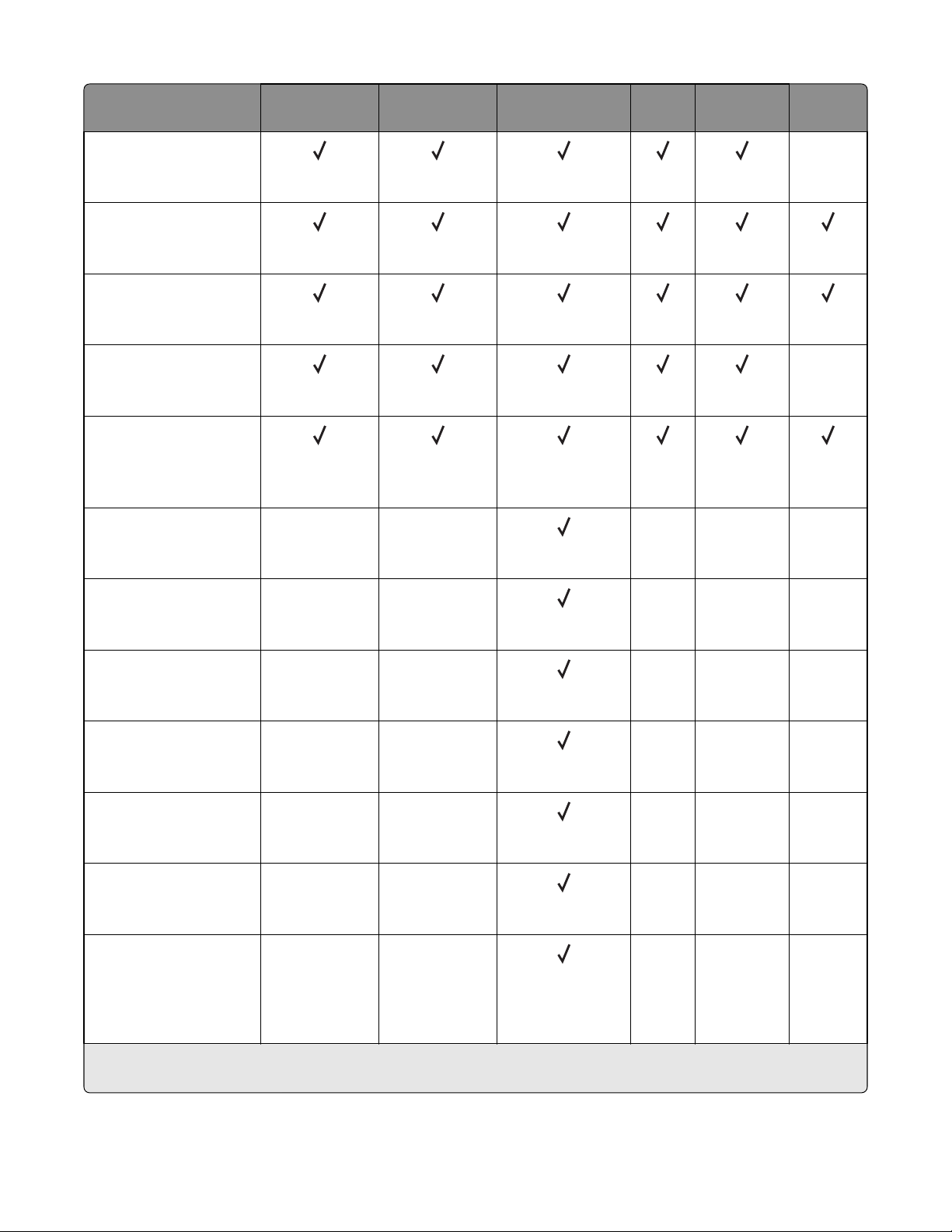
7016
Paper size and dimension Standard
550‑sheet tray
Executive
184.2 x 266.7 mm
(7.25 x 10.5 in.)
Oficio (México)
215.9 x 340.4 mm
(8.5 x 13.4 in.)
Folio
215.9 x 330.2 mm
(8.5 x 13 in.)
Statement
139.7 x 215.9 mm
(5.5 x 8.5 in.)
Universal
*
76.2 x 127 mm (3 x 5 in.) to
215.9 x 359.92 mm
(8.5 x 14.17 in.)
7 3/4 Envelope (Monarch)
98.4 x 190.5 mm
(3.875 x 7.5 in.)
Optional 250‑ or
550‑sheet tray
Multipurpose
feeder
ADF Scanner
glass
Duplex
mode
X
X
XX XX X
9 Envelope
XX
XX X
98.4 x 226.1 mm
(3.875 x 8.9 in.)
10 Envelope
XX
XX X
104.8 x 241.3 mm
(4.12 x 9.5 in.)
DL Envelope
XX
XX X
110 x 220 mm
(4.33 x 8.66 in.)
C5 Envelope
XX
XX X
162 x 229 mm
(6.38 x 9.01 in.)
B5 Envelope
XX
XX X
176 x 250 mm
(6.93 x 9.84 in.)
Other Envelope
XX
XX X
85.7 x 165 mm to
215.9 x 355.6 mm
(3.375 x 6.50 in. to
8.5 x 14 in.)
*
Universal is supported in duplex mode only if the width is at least 210 mm (8.27 in.) and the length is at least 279.4 mm
(11 in.). The smallest supported Universal size is supported only in the multipurpose feeder.
General information
31
Page 32
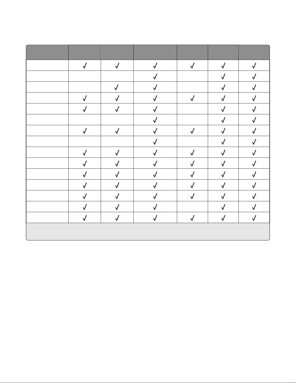
Supported paper types and weights
Note: Labels, transparencies, envelopes, and card stock always print at a reduced speed.
7016
Paper type Standard
550‑sheet tray
Plain paper
Card stock X X X
Transparencies X
Recycled
Paper labels X
Bond X X X
Envelope
Rough envelope X X X
Letterhead
Preprinted
Colored paper
Light paper
2
250‑ or
550‑sheet tray
1
Multipurpose
feeder
Duplex mode ADF Scanner glass
X
Heavy paper
Rough/Cotton X
Custom Type [x]
1
Transparencies are supported only in the 250‑sheet tray.
2
Use envelopes that lie flat when individually placed on a table facedown.
Data security notice
This printer contains various types of memory that are capable of storing device and network settings, information
from embedded solutions, and user data. The types of memory, along with the types of data stored by each, are
described below.
• Volatile memory—This device utilizes standard Random Access Memory (RAM) to temporarily buffer user data
during simple print and copy jobs.
• Non-volatile memory—This device may utilize two forms of non-volatile memory: EEPROM and NAND (flash
memory). Both types are used to store the operating system, device settings, network information, scanner and
bookmark settings, and embedded solutions.
General information
32
Page 33

• Hard disk memory—Some devices have a hard disk drive installed. The printer hard disk is designed for device-
specific functionality and cannot be used for long term storage for data that is not print-related. The hard disk does
not provide the capability for users to extract information, create folders, create disk or network file shares, or
transfer FTP information directly from a client device. The hard disk can retain buffered user data from complex
print jobs, as well as form data and font data.
To erase volatile memory, turn off the printer.
To erase non-volatile memory, see the menu item under “Configuration menu” on page 186 pertaining to this.
To erase the printer hard disk, see the menu item under “Configuration menu” on page 186 pertaining to this.
The following parts are capable of storing memory:
• printer control panel
• UICC (User Interface Controller Card)
• controller board
• optional hard drives
Note: The printer control panel and controller board contain NVRAM.
After removing the old part, it must be returned to your next level of support.
7016
Tools required for service
Flat-blade screwdrivers, various sizes
#1 Phillips screwdriver, magnetic
#2 Phillips screwdriver, magnetic
#2 Phillips screwdriver, magnetic short-blade
Needle‑nose pliers
Diagonal side cutters
Spring hook
Feeler gauges
Analog or digital multimeter
Flashlight (optional)
General information
33
Page 34

7016
34
Page 35

Diagnostic information
• “Troubleshooting overview” on page 35
• “Fixing print quality issues” on page 37
• “Paper jams” on page 45
• “Understanding the printer messages” on page 88
• “User attendance messages (0–99.99)” on page 103
• “Printer hardware errors” on page 106
• “Input/output option hardware errors” on page 133
• “ADF/Scanner hardware errors” on page 137
CAUTION—SHOCK HAZARD: Remove the power cord from the electrical outlet before you connect or
disconnect any cable or electronic card or assembly for personal safety and to prevent damage to the printer.
Disconnect any connections between the printer and PCs/peripherals.
CAUTION—POTENTIAL INJURY: The printer weight is greater than 18kg (40 lb) and requires two or more
trained personnel to lift it safely. Use the hand holds on the side of the printer. Make sure your fingers are not
under the printer when you lift or set the printer on the floor or another stable surface.
7016
CAUTION—HOT SURFACE: The inside of the printer might be hot. To reduce the risk of injury from a hot
component, allow the surface to cool before touching it.
Troubleshooting overview
• “Performing the initial troubleshooting check” on page 35
• “Power‑on Reset (POR) sequence” on page 36
• “Using Safe Mode” on page 36
Performing the initial troubleshooting check
Before you start the troubleshooting procedures, perform the following checks:
• With the power cord unplugged from the wall outlet, check that the cord is free from breakage, short-circuits,
disconnected wires, or incorrect connections.
• Make sure the printer is properly grounded. Check the power cord ground terminal.
• Make sure the power supply line voltage is within 10% of the rated line voltage.
• Make sure the machine is securely installed on a level surface in a well-ventilated area.
• Make sure the room temperature is between 16 and 32°C (60 and 90°F) and that the relative humidity is between
20 and 80%.
• Avoid sites generating ammonia gas, high temperature, high humidity (near water faucets, kettles, humidifiers),
cold spaces, near open flames, and dusty areas.
• Avoid sites exposed to direct sunlight.
• Make sure the paper is the recommended paper for this printer.
• Make a trial print with paper from a newly opened package, and check the result.
Diagnostic information
35
Page 36

Power‑on Reset (POR) sequence
When you turn the printer on, it performs a POR sequence.
Check for correct POR functioning of the base printer by observing the following:
1 The control panel indicator light turns on.
2 The control panel display turns on.
3 A splash screen appears on the display.
4 The cooling fan turns on.
5 The fuser heater turns on.
Note: The fuser takes longer to warm up from a cold start than a warm start.
6 The main drive motor turns on.
7 The EP drive assembly drives the developer shaft located in the imaging unit.
8 The exit rollers turn.
9 The control panel indicator light blinks.
7016
10 Ready appears on the display.
Using Safe Mode
Safe Mode lets the printer continue to operate in a special limited mode in which it attempts to continue offering as
much functionality as possible despite known issues.
Warning—Potential Damage: Safe Mode is intended as a short‑term workaround and should be used only in the
case of a non‑critical error when a print job must be completed before service can be arranged to repair the printer.
The printer must be returned to standard operating mode before diagnostics can be run or full‑function printing can
continue.
You can enter Safe Mode in one of the following ways:
• Enable Safe Mode from the Configuration menu, and then POR the printer.
• Press the Stop and Back keys, and then POR the printer.
Return the printer to standard operating mode to service the printer and return to full‑function printing.
Safe Mode print behavior
The following table outlines the behavior for this printer model while in Safe Mode:
Safe Mode engine features Engine behavior Control panel behavior
Simplex printing only Will report that no duplexer is installed. Duplex print option will not be
Ignore duplex sensor
selectable.
Ignore bin full sensor Bin full messages will not be reported. Bin full messages will not occur.
Print at narrow media operating point Pages will be printed slower. N/A
Ignore narrow media sensor Narrow media will print without
restrictions.
Diagnostic information
N/A
36
Page 37

Safe Mode engine features Engine behavior Control panel behavior
Ignore all input options Will report that only Tray 1 is installed. Only Tray 1 and the MPF will be
selectable.
7016
Ignore all output options Will not report any installed finishing
options.
Use large interpage gaps Pages will have large interpage gaps. N/A
Finishing options will not be selectable.
Fixing print quality issues
• “Initial print quality check” on page 37
• “Gray background or toner fog on prints” on page 38
• “Repeating defects” on page 39
• “Printer is printing blank pages” on page 39
• “Printer is printing solid black pages” on page 40
• “Shadow images appear on prints” on page 40
• “Skewed print” on page 41
• “Streaked horizontal or vertical lines appear on prints” on page 43
• “Toner rubs off” on page 44
• “Toner specks appear on prints” on page 45
The symptoms described in this chapter might require replacement of one or more CRUs (Customer Replaceable Units)
designated as supplies or maintenance items, which are the responsibility of the customer. With the customer's
permission, you might need to install a developer (toner) cartridge.
Initial print quality check
Before troubleshooting specific print problems, complete the following initial print quality check:
1 The printer must be in a location that follows the recommended operating environment specifications. See
“Operating environment” on page 414.
2 Check the life status of all supplies. Any supply that is low should be replaced.
3 Load 20‑lb plain letter or A4 paper. Make sure the paper guides are properly set and locked. From the control panel,
set the paper size and type to match the paper loaded in the tray.
4 Print a Menu settings page. Be sure to keep the original Menu settings page to restore the customer's custom
settings if needed.
5 Verify on the Menu settings page if the following are set to their default values:
• Print resolution: 600 dpi
• Toner darkness: 8
6 Inspect the transfer roll for damage. Replace if damaged.
7 Inspect the toner cartridge and imaging unit for damage. Replace if damaged.
8 Print the Print quality pages to see if the problem remains. Use Tray 1 to test print quality problems.
Diagnostic information
37
Page 38

7016
9 Print a Print quality test page, and then look for variations in the print from what is expected. Verify if the settings
under EP Setup are set to their default values. See “EP Defaults” on page 178.
10 Check to ensure the correct printer driver for the installed software is being used. An incorrect printer driver for
the installed software can cause problems. Incorrect characters could print, and the copy may not fit the page
correctly.
Gray background or toner fog on prints
Leading edge
ABCDE
ABCDE
ABCDE
Actions Yes No
Step 1
Check the cartridge plunger.
Is the cartridge plunger properly attached to the front door and is the
spring functioning properly?
Step 2
Remove any contamination from the CTLS contacts. Perform a print test.
Does the problem remain?
Step 3
Check the CTLS for damage.
Is it free of damage?
Step 4
Check the transfer roll for surface contamination or excessive wear.
Is it free of contamination and wear?
Trailing edge
Go to step 2. Replace the cartridge
plunger. See “Cartridge
plunger removal” on
page 251.
Go to step 3. The problem is solved.
Go to step 4. Replace the printer.
Go to step 5. Replace the transfer
roll. See “Transfer roll
removal” on page
250.
Step 5
Check the transfer roll left contact spring for damage.
Is it free of damage?
Diagnostic information
38
Replace the power
supply. See “Power
supply removal” on
page 281.
Replace the printer.
Page 39
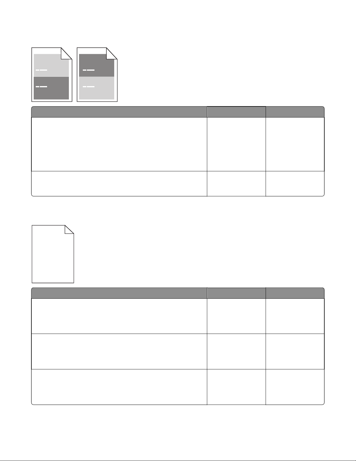
Repeating defects
Actions Yes No
7016
Step 1
Measure the distance between defects. Is the distance between defects
equal to any of the following?
• 3.82 in. (97 mm)
• 1.85 in. (47 mm)
• 1.5 in. (38 mm)
Step 2
Is the distance between defects equal to 3.15 in. (80 mm)?
Printer is printing blank pages
Replace the imaging
unit.
Replace the fuser. See
“Fuser removal” on
page 302.
Go to step 2.
Contact the next level
of support.
Actions Yes No
Step 1
Check the toner cartridge level.
Is the toner level low?
Step 2
Check the imaging unit for wear or damage.
Is it free of wear or damage?
Step 3
Check the transfer roll for surface contamination or excessive wear.
Is it free of contamination and wear?
Replace the toner
cartridge.
Go to step 3. Replace the imaging
Go to step 4. Replace the transfer
Go to step 2.
unit.
roll.
Diagnostic information
39
Page 40
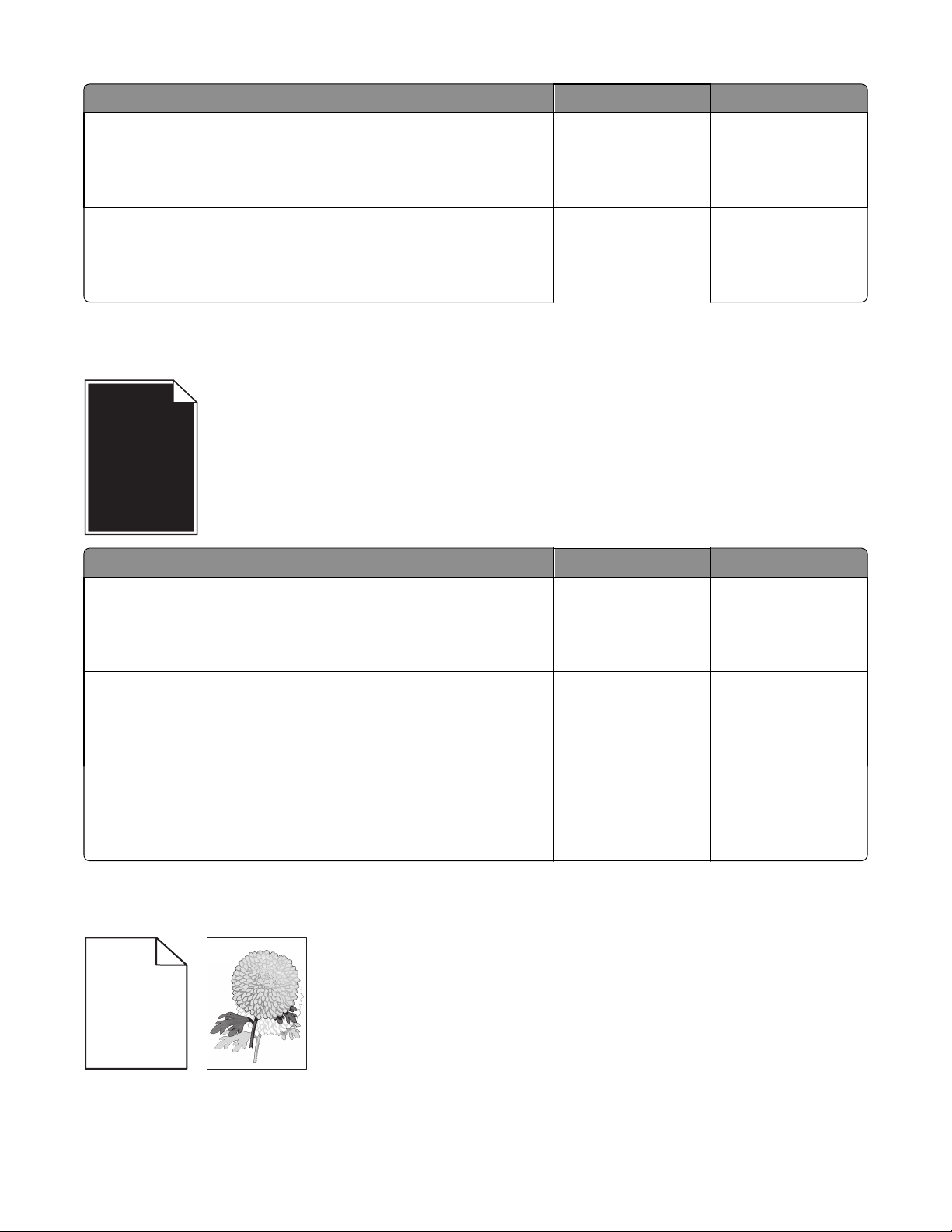
Actions Yes No
7016
Step 4
Check the transfer roll left contact spring for damage.
Is it free of damage?
Step 5
Reseat the cables JLSU1 and J6 on the controller board.
Does the problem remain?
Go to step 5. Replace the printer.
Replace the power
supply.
Printer is printing solid black pages
Actions Yes No
The problem is solved.
Step 1
Check the imaging unit for damage.
Is it free of damage?
Step 2
Remove any contamination from the imaging unit contacts.
Does the problem remain?
Step 3
Check the imaging unit contacts for damage.
Are they free of damage?
Shadow images appear on prints
Leading edge
ABCD
ABCD
ABCD
ABCD
Go to step 2. Replace the imaging
unit.
Go to step 3. The problem is solved.
Replace the power
supply. See “Power
supply removal” on
page 281.
Replace the printer.
Trailing edge
Diagnostic information
40
Page 41

Actions Yes No
) )
7016
Step 1
Does the shadow image appear every two pages?
Step 2
Check the redrive assembly for wear or damage.
Is it free of wear or damage?
Step 3
Check the transfer roll for surface contamination or excessive wear.
Is it free of contamination and wear?
Step 4
Check the following fuser components for wear or damage:
• Gears
• Exit rollers
• Belt fuser
Are they free of damage?
Step 5
a Turn off the printer.
b Remove the rear door and cover.
c Disconnect the fuser cable connected to PCN5 of the power supply.
d Check for approximate correct resistance on the fuser cable:
• 220V fuser—43 ohms
• 110V fuser—10 ohms
• 100V fuser—8 ohms
Go to step 2. Go to step 3.
Go to step 3. Replace the redrive
assembly. See “Redrive
assembly removal” on
page 301.
Go to step 4. Replace the transfer
roll. See “Transfer roll
removal” on page
250.
Go to step 5. Replace the fuser. See
“Fuser removal” on
page 302.
The problem is solved. Replace the fuser. See
“Fuser removal” on
page 302.
Is the resistance equal to any of the above values?
Skewed print
ABCDE
ABCDE
ABCDE
Diagnostic information
41
Page 42

Actions Yes No
7016
Step 1
a POR into the Diagnostics menu and perform a print test:
Diagnostics Menu > Print Tests > Tray 1
b Adjust the margins if necessary:
Diagnostics Menu > Registration
Does the error remain?
Step 2
Does the skew appear every two pages?
Step 3
a Check the media source.
b If the media is from tray 1, go to step 4.
If the media is from the MPF, go to step 6.
Step 4
Make sure the pick tires are free of debris. Check for wear or damage.
Are they free of wear or damage?
Step 5
Check the lift plate on the input tray for damage.
Go to step 2. The problem is solved.
Go to step 9. Go to step 3.
Go to step 5. Replace the pick tires.
Go to step 11. Replace the input tray.
Is it free of damage?
Step 6
Make sure the MPF pick roller and separator pad are free of debris. Check
for wear or damage.
Are they free of wear or damage?
Step 7
Check the MPF gearbox for wear or damage.
Is it free of wear or damage?
Step 8
Make sure the front input guide rollers are free of debris. Check for wear
or damage.
Are they free of wear or damage?
Step 9
Make sure the redrive rollers are free of debris. Check for wear or damage.
Are they free of wear or damage?
Go to step 7. Replace the MPF pick
roller and separator
pad. See “MPF pick
roller removal” on
page 271 and
“Separator pad
removal” on page
278.
Go to step 8. Replace the MPF
gearbox. See “MPF
gearbox removal” on
page 227.
Go to step 11. Replace the front input
guide. See “Front input
guide removal” on
page 276.
Go to step 10. Replace the redrive
assembly. See “Redrive
assembly removal” on
page 301.
Diagnostic information
42
Page 43
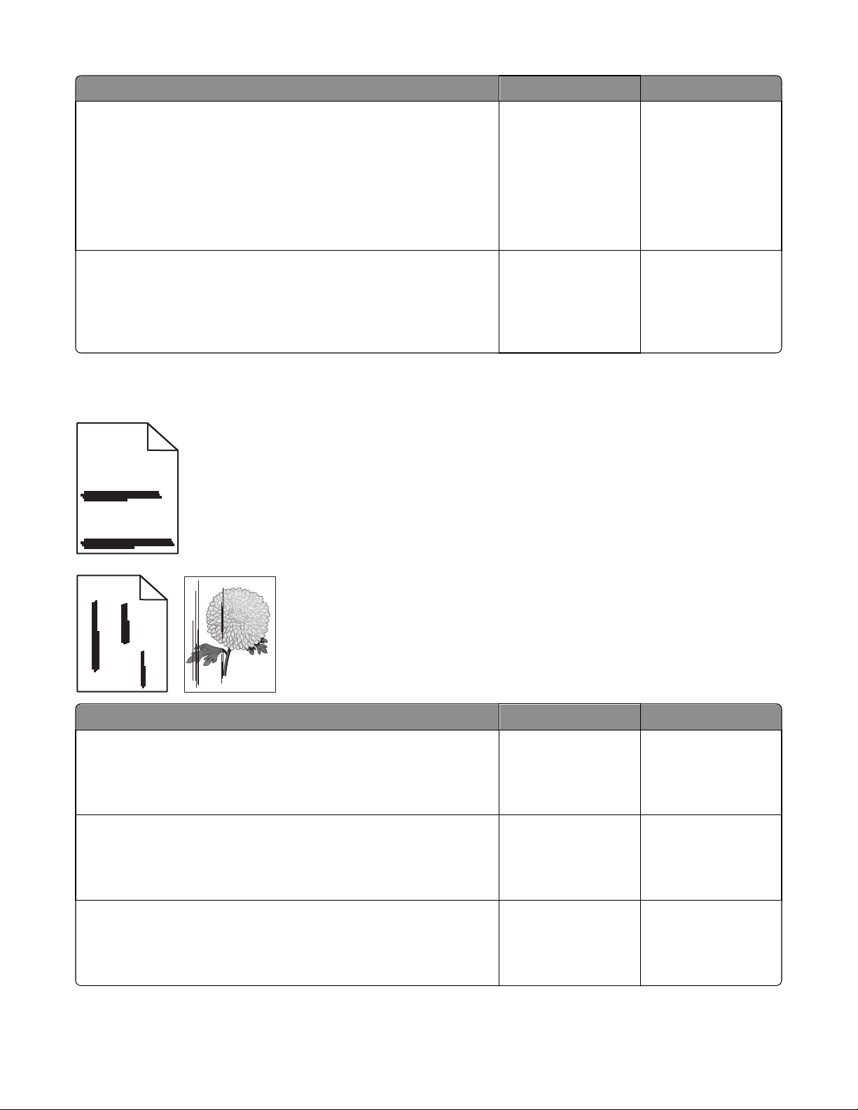
Actions Yes No
7016
Step 10
a Remove the left cover.
b POR into the Diagnostics menu and perform a duplex test:
Diagnostics Menu > Duplex Tests
c Observe the reverse solenoid for proper operation.
Does it properly operate?
Step 11
Make sure the input roller/deskew assembly is free of debris. Check for
wear or damage.
Are they free of wear or damage?
Go to step 11. Replace the reverse
Contact the next level
of support.
Streaked horizontal or vertical lines appear on prints
ABCDE
ABCDE
solenoid. See “Reverse
solenoid removal” on
page 230.
Replace the printer.
ABCDE
Leading edge
ABCDE
ABCDE
ABCDE
Actions Yes No
Step 1
Check the imaging unit for wear or damage.
Is it free of wear or damage?
Step 2
Make sure the paper path is free of debris or toner contamination.
Does the problem remain?
Step 3
Check the transfer roll for contamination or excessive wear.
Trailing edge
Go to step 2. Replace the imaging
unit.
Go to step 3. The problem is solved.
Go to step 4. Replace the transfer
roll.
Is it free of contamination or wear?
Diagnostic information
43
Page 44
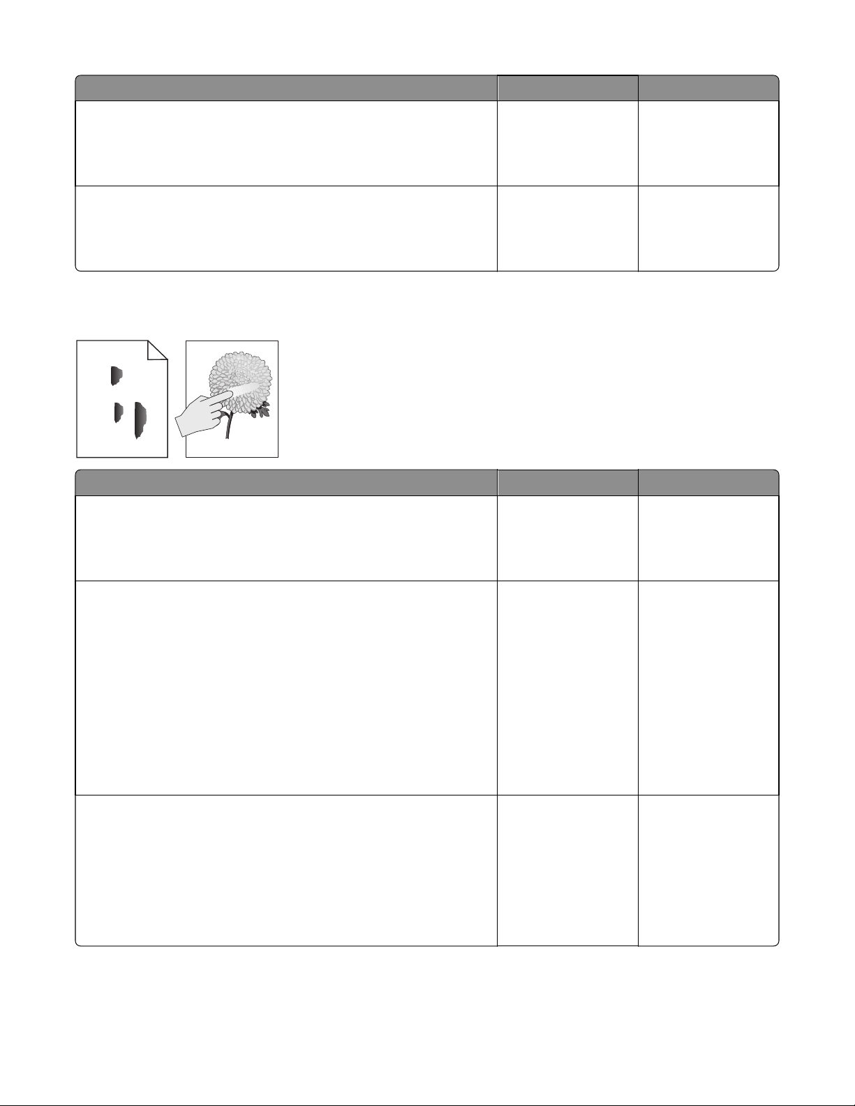
Actions Yes No
7016
Step 4
Remove the fuser and check for damage or debris on the rollers and belts.
Is it free of damage and debris?
Step 5
Reseat the cables JLSU1 and J6 on the controller board.
Does the problem remain?
Go to step 5. Replace the fuser.
Replace the LSU. The problem is solved.
Toner rubs off
Leading edge
ABC
DEF
Trailing edge
Actions Yes No
Step 1
Check if the fuser screws are tightly fastened.
Go to step 2. Tighten the screws.
Are they tightly fastened?
Step 2
a Turn off the printer.
b Remove the rear door and cover.
c Disconnect the fuser cable connected to PCN5 of the power supply.
d Check for approximate correct resistance on the fuser cable:
• 220V fuser—43 ohms
• 110V fuser—10 ohms
• 100V fuser—8 ohms
Is the resistance equal to any of the above values?
Step 3
Check the following fuser components for wear or damage:
• Gears
• Exit rollers
• Belt fuser
Are they free of damage?
Go to step 3. Replace the fuser. See
“Fuser removal” on
page 302.
Replace the power
supply. See “Power
supply removal” on
page 281.
Replace the fuser. See
“Fuser removal” on
page 302.
Diagnostic information
44
Page 45

Toner specks appear on prints
Actions Yes No
7016
Step 1
Check the imaging unit for wear or damage.
Is it free of wear or damage?
Step 2
Make sure the paper path is free of debris or toner contamination.
Does the problem remain?
Step 3
Check the transfer roll for contamination or excessive wear.
Is it free of contamination or wear?
Step 4
Remove the fuser and check for damage or debris on the rollers and belts.
Is it free of damage and debris?
Step 5
Reseat the cables JLSU1 and J6 on the controller board.
Does the problem remain?
Go to step 2. Replace the imaging
unit.
Go to step 3. The problem is solved.
Go to step 4. Replace the transfer
roll.
Go to step 5. Replace the fuser.
Replace the LSU. The problem is solved.
Paper jams
• “Avoiding jams” on page 46
• “Understanding jam messages and locations” on page 47
• “200 paper jams” on page 48
• “202 paper jams” on page 57
• “23y paper jams” on page 60
• “24y paper jams” on page 62
• “25y paper jams” on page 71
• “28y paper jams” on page 74
• “29y.xx paper jams” on page 75
Diagnostic information
45
Page 46
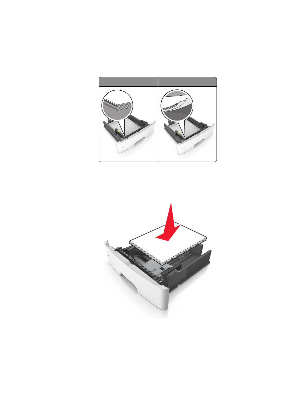
• “45y paper jams” on page 76
Avoiding jams
Load paper properly
•
Make sure paper lies flat in the tray.
7016
Correct loading of paper Incorrect loading of paper
• Do not remove a tray while the printer is printing.
• Do not load a tray while the printer is printing. Load it before printing, or wait for a prompt to load it.
• Do not load too much paper. Make sure the stack height is below the maximum paper fill indicator.
• Do not slide the paper into the tray. Load paper as shown in the illustration.
• Make sure the guides in the tray or the multipurpose feeder are properly positioned and are not pressing tightly
against the paper or envelopes.
• Push the tray firmly into the printer after loading paper.
Diagnostic information
46
Page 47
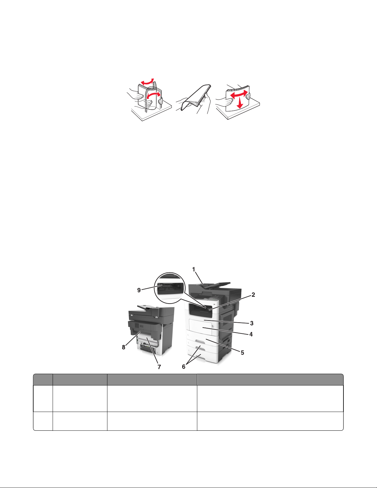
Use recommended paper
•
Use only recommended paper or specialty media.
• Do not load wrinkled, creased, damp, bent, or curled paper.
• Flex, fan, and straighten paper before loading it.
• Do not use paper that has been cut or trimmed by hand.
• Do not mix paper sizes, weights, or types in the same tray.
• Make sure the paper size and type are set correctly on the computer or printer control panel.
• Store paper according to manufacturer recommendations.
Understanding jam messages and locations
7016
When a jam occurs, a message indicating the jam location and information to clear the jam appears on the printer
display. Open the doors, covers, and trays indicated on the display to remove the jam.
Notes:
• When Jam Assist is set to On, the printer automatically flushes blank pages or pages with partial prints to the
standard bin after a jammed page has been cleared. Check your printed output stack for discarded pages.
• When Jam Recovery is set to On or Auto, the printer reprints jammed pages. However, the Auto setting does not
guarantee that the page will print.
Jam access area Printer control panel message What to do
1 Automatic
document feeder
(ADF)
2 Standard bin [x]‑page jam, clear standard
[x]‑page jam, open ADF to clear
jam. [28y.xx]
bin. [20y.xx]
Diagnostic information
47
Remove all paper from the ADF tray, and then remove the
jammed paper.
Remove the jammed paper.
Page 48

Jam access area Printer control panel message What to do
7016
3 Front door [x]‑page jam, open front
door. [20y.xx]
4 Multipurpose
feeder
5 Tray 1 [x]‑page jam, remove tray 1 to
6 Tray [x] [x]‑page jam, open tray
7 Rear door [x]‑page jam, open rear
8 Finisher rear door [x]-page jam, remove all pages
9 Finisher output bin [x]-page jam, remove all pages
[x]‑page jam, clear manual
feeder. [25y.xx]
clear duplex. [23y.xx]
[x]. [24y.xx]
door. [20y.xx]
from the finisher’s accumulator.
Leave paper in bin [45y.xx]
from the output bin. Leave paper
in bin [45y.xx]
Open the front door, then remove the toner cartridge and
imaging unit, and then the jammed paper.
Remove all paper from the multipurpose feeder, and then
remove the jammed paper.
Pull out tray 1 completely, then push the front duplex flap
down, and then remove the jammed paper.
Note: You may need to open the rear door to clear
some 23y.xx paper jams.
Pull the indicated tray out, and then remove the jammed
paper.
Open the rear door, and then remove the jammed paper.
• Open the finisher rear door, and then remove the
jammed paper.
• Open the trap door, and then remove the jammed
paper.
• Move the left tamper arm to the left and the right
tamper arm to the right, and then remove the jammed
paper from the finisher bin.
• Open the finisher rear door and the trap door, and
then remove any jammed pages.
200 paper jams
[x]‑page jam, clear standard bin. [20y.xx]
1 Firmly grasp the jammed paper on each side, and then gently pull it out.
Note: Make sure all paper fragments are removed.
2 From the printer control panel, touch Done to clear the message and continue printing.
Diagnostic information
48
Page 49
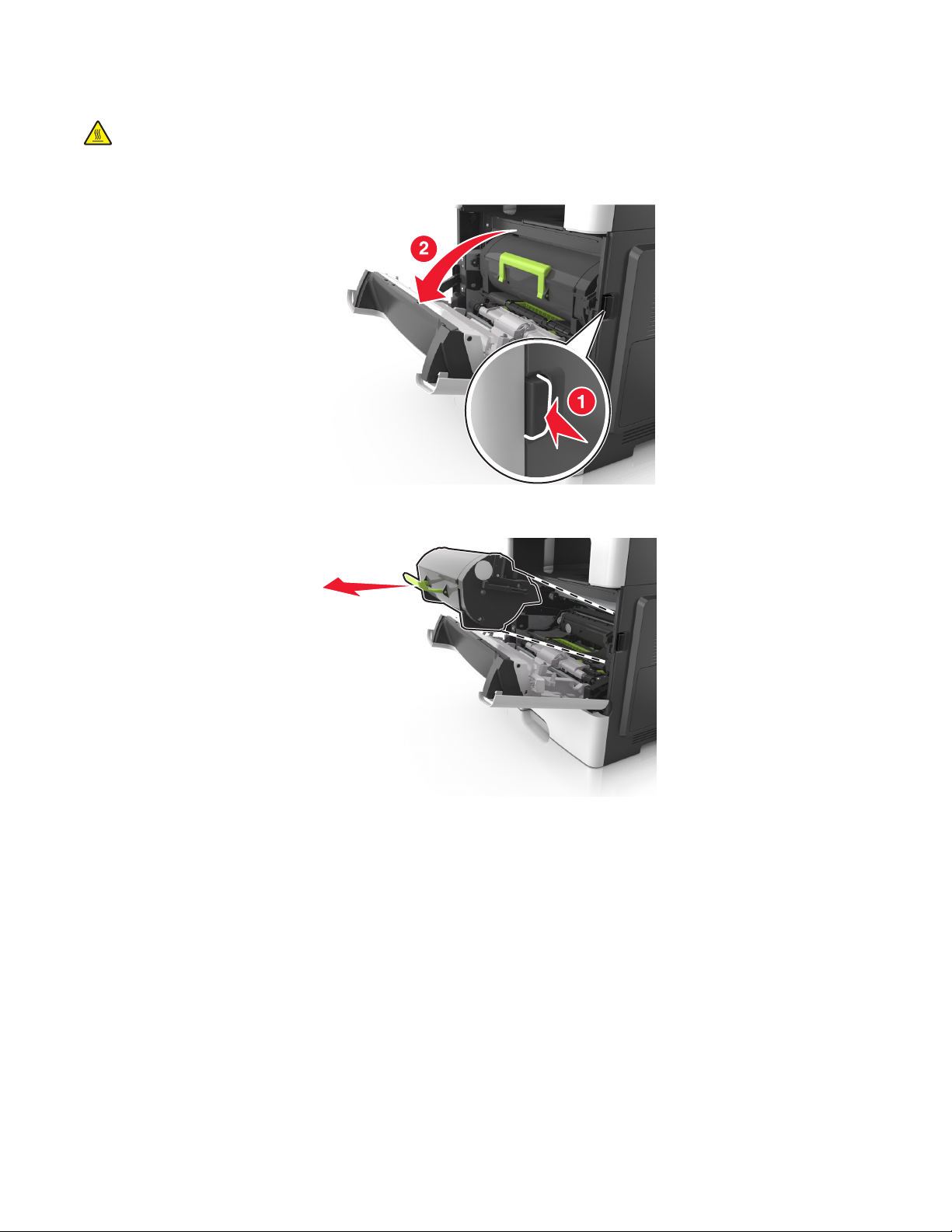
[x]‑page jam, open front door. [20y.xx]
CAUTION—HOT SURFACE: The inside of the printer might be hot. To reduce the risk of injury from a hot
component, allow the surface to cool before touching it.
1 Press the button on the right side of the printer, and then open the front door.
7016
2 Pull out the toner cartridge using the handle.
Diagnostic information
49
Page 50
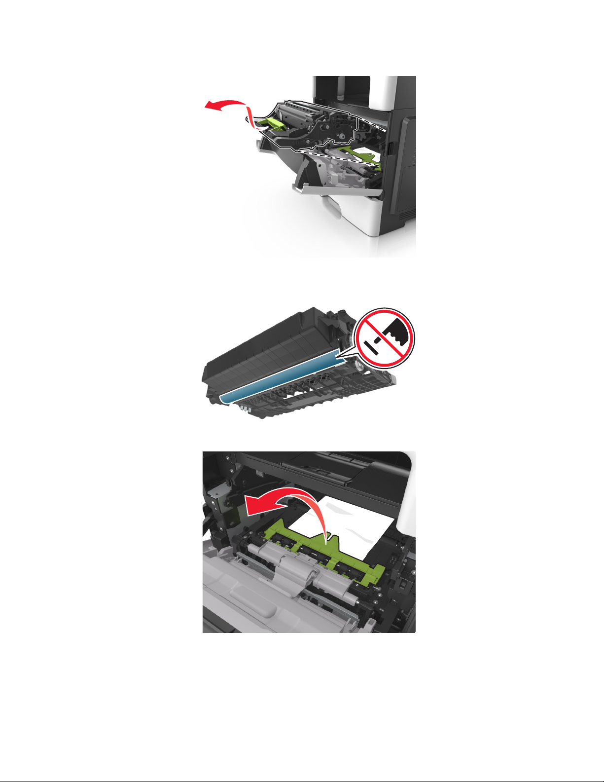
3 Lift the green handle, and then pull out the imaging unit from the printer.
Warning—Potential Damage: Do not touch the shiny blue photoconductor drum under the imaging unit. Doing
so may affect the quality of future print jobs.
7016
4 Lift the green flap in front of the printer.
5 Place the imaging unit aside on a flat, smooth surface.
Warning—Potential Damage: Do not expose the imaging unit to direct light for more than 10 minutes.
Extended exposure to light may cause print quality problems.
Diagnostic information
50
Page 51

7016
6 Firmly grasp the jammed paper on each side, and then gently pull it out.
Note: Make sure all paper fragments are removed.
7 Insert the imaging unit by aligning the arrows on the side rails of the unit with the arrows on the side rails inside
the printer, and then insert the imaging unit into the printer.
8 Insert the toner cartridge by aligning the side rails of the cartridge with the arrows on the side rails inside the printer,
and then insert the cartridge into the printer.
Diagnostic information
51
Page 52
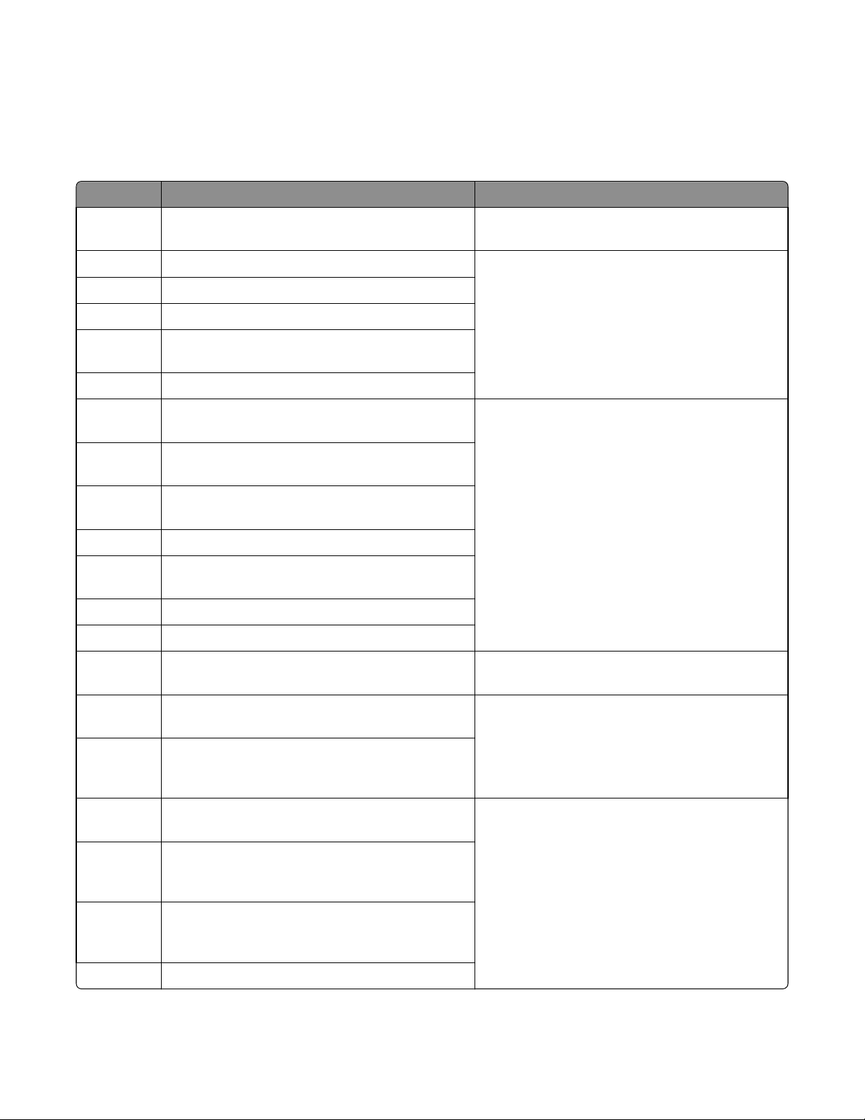
9 Close the front door.
10 From the printer control panel, select Continue to clear the message and continue printing.
200 paper jam messages
Error code Description Action
200.01 Input sensor covered during warm-up sequence. Go to “Sensor (input) static jam service check” on
page 53.
200.02 Input sensor covered too quickly. Go to “Sensor (input) early/late arriving service
200.03 Media did not reach input sensor from MPF.
200.05 Input sensor covered too long.
200.07 Input sensor failed to become uncovered from sheet
ahead.
200.08 Page arrive at input senor at unexpected time.
check” on page 54.
7016
200.09 Printhead did not receive proper motor feedback to
start laser servo.
200.10 Printhead motor not locked when media reaches the
input sensor.
200.11 Print head motor fell out of lock after page reaches the
input sensor.
200.12 Printhead was not ready for media.
200.13 Media at input sensor is not the next media to be
imaged.
200.14 Media reached the input sensor before EP was ready.
200.15 Image data did not start on time.
200.16 Fuser motor stalled. Go to “Main drive motor control jam service check”
200.19 Page that was successfully picked from option tray
never reached the input sensor.
200.21 No response from paper port driver while waiting for
the source to deactivate the Input Source Ready flag
to indicate it has initiated picking.
200.23 Laser servo never started due to potential conflict
with the transfer servo.
Go to “Sensor (input) image jam service check” on
page 55.
on page 56.
Go to “Sensor (input) early/late arriving service
check” on page 54.
Go to “Sensor (input) image jam service check” on
page 55.
200.24 Measured gap at input sensor too small to meet video
delivery requirements. (Not enough time since prior
image finished to start new image).
200.29 Printhead drive control out of range due to an
external event beyond what the control is designed
to handle.
200.30 Invalid printhead NVRAM.
Diagnostic information
52
Page 53

Error code Description Action
7016
200.31 Paper, in the middle of a job, at input sensor before
interrupt occurred.
200.32 Detected cover switch bounce.
200.33 Input sensor covered too quickly.
200.38 Interpage servo gap smaller than expected for galvo
offset target evaluation.
200.42 Rogue sheet at ACM sensor while flushing the paper
path prior to declaring tray 1 source empty.
200.44 Page from tray 1 did not reach the input sensor (or
the manual feed sensor, if present) after multiple pick
attempts. Page did make it out of the tray at least as
far as the ACM sensor.
200.45 During warm up flush, sheet detected too long over
input sensor.
Go to “Sensor (input) early/late arriving service
check” on page 54.
Go to “Sensor (input) early/late arriving service
check” on page 54.
Sensor (input) static jam service check
Action Yes No
Step 1
Check the input sensor area for jammed media fragments.
Go to step 2. Clear the paper path of
any media fragments.
Is the paper path free of partially fed or jammed media?
Step 2
Check the jam access cover if it is blocking the input sensor.
Is it blocking the input sensor?
Step 3
Check the input sensor cable for proper connection.
Is it properly connected?
Step 4
POR into the Diagnostics menu and perform a sensor test:
Diagnostics Menu > Base Sensor Test > Input.
Does the sensor state on the control panel display change when it is
toggled?
Step 5
Does the error remain?
Replace the jam access
cover. See “Jam access
cover removal” on
page 273.
Go to step 4. Reseat the cable.
Go to step 5. Replace the input
Contact the next level
of support.
Go to step 3.
sensor. See “Duplex
sensor and input
sensor removal” on
page 283.
The problem is solved.
Diagnostic information
53
Page 54

Sensor (input) early/late arriving service check
Action Yes No
7016
Step 1
Check the paper source.
Is the paper from the MPF?
Step 2
Check the MPF pick roller and separator pad for damage and
contamination.
Are they free of damage and contamination?
Step 3
Check the MPF solenoid for proper operation:
a Remove the left cover.
b POR into the Diagnostics menu and perform a feed test:
Diagnostics Menu > Input Tray Tests > Feed Test >
Multipurpose feeder
c Check if the MPF solenoid moves when doing the feed test.
Does it move when doing the feed test?
Go to step 2. Go to step 5.
Go to step 3. Replace the MPF pick
roller and separator
pad. See “MPF pick
roller removal” on
page 271 and
“Separator pad
removal” on page
278.
Go to step 4. Replace the MPF
solenoid. See “MPF
solenoid removal” on
page 225.
Step 4
Make sure the MPF gearbox spring is properly installed and free of
damage. Check the MPF gearbox for wear or damage.
Are they free of wear or damage?
Step 5
Check the input sensor area for jammed media fragments.
Is the paper path free of partially fed or jammed media?
Step 6
Check the jam access cover if it is blocking the input sensor.
Is it blocking the input sensor?
Step 7
Check the input sensor cable for proper connection.
Is it properly connected?
Go to step 5. Replace the MPF
gearbox. See “MPF
gearbox removal” on
page 227.
Go to step 6. Clear the paper path of
any media fragments.
Replace the jam access
cover. See “Jam access
cover removal” on
page 273
Go to step 8. Reseat the cable.
Go to step 7.
Diagnostic information
54
Page 55

Action Yes No
7016
Step 8
POR into the Diagnostics menu and perform a sensor test:
Diagnostics Menu > Base Sensor Test > Input
Does the sensor state on the control panel display change when it is
toggled?
Step 9
Does the error remain?
Go to step 9. Replace the input
Contact the next level
of support.
Sensor (input) image jam service check
Action Yes No
Step 1
Check the LSU cables for proper connection.
Are they properly connected?
Step 2
Inspect the LSU cables and connectors.
Are they free of damage?
Go to step 2. Reseat the cables.
Go to step 3. Replace the LSU. See
sensor. See “Duplex
sensor and input
sensor removal” on
page 283.
The problem is solved.
“Laser scanning unit
(LSU) removal” on
page 310.
Step 3
Check the input sensor cable for proper connection.
Is it properly connected?
Step 4
POR into the Diagnostics menu and perform a feed test:
Diagnostics Menu > Input Tray Tests > Feed Tests > Tray 1
Does it pass the test?
Step 5
POR into the Diagnostics menu and perform a sensor test:
Diagnostics Menu > Base Sensor Test > Input
Does the sensor state on the control panel display change when it is
toggled?
Step 6
Check the controller board for any damage.
Is it free of damage?
Step 7
Does the error remain?
Go to step 4. Reseat the cable.
Go to step 5. Replace the LSU. See
“Laser scanning unit
(LSU) removal” on
page 310.
Go to step 6. Replace the input
sensor. See “Duplex
sensor and input
sensor removal” on
page 283.
Go to step 7. Replace the controller
board. See “Controller
board removal” on
page 239.
Contact the next level
of support.
The problem is solved.
Diagnostic information
55
Page 56

Main drive motor control jam service check
Action Yes No
7016
Step 1
a Remove the main drive gearbox.
b Check the main drive gearbox cable for proper connection.
Is it properly connected?
Step 2
a Remove the main drive gearbox.
b Check the gears of main drive gearbox for wear or damage.
Are they free of wear or damage?
Step 3
Check the main drive motor for proper operation:
a Remove the main drive gearbox.
Note: Do not disconnect the main drive gearbox cable.
b POR into the Diagnostics menu and perform a feed test:
Diagnostics menu > Input Tray Tests > Feed Test >
Select any input source
c Check if the main drive motor rotates when doing the feed test.
Does it rotate when doing the feed test?
Go to step 2. Reseat the cable.
Go to step 3. Replace the main drive
gearbox. See “Main
drive gearbox
removal” on page
223.
Go to step 4. Replace the main drive
gearbox. See “Main
drive gearbox
removal” on page
223.
Step 4
Check the fuser gear for damage or toner contamination.
Is it free of damage and contamination?
Replace the controller
board. See “Controller
board removal” on
page 239.
Replace the fuser. See
“Fuser removal” on
page 302.
Diagnostic information
56
Page 57

202 paper jams
[x]‑page jam, open rear door. [20y.xx]
1 Open the front door to loosen the jammed paper in the rear door.
7016
2 Gently pull down the rear door.
CAUTION—HOT SURFACE: The inside of the printer might be hot. To reduce the risk of injury from a hot
component, allow the surface to cool before touching it.
3 Firmly grasp the jammed paper on each side, and then gently pull it out.
Note: Make sure all paper fragments are removed.
Diagnostic information
57
Page 58
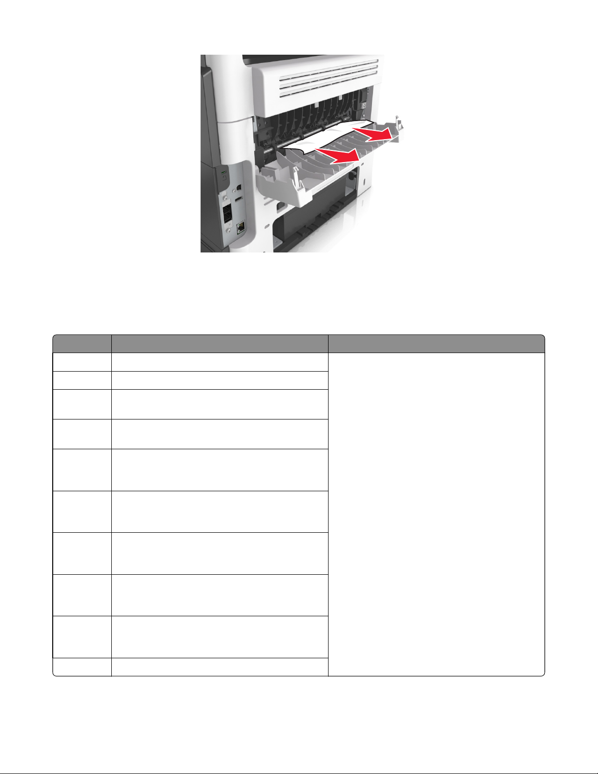
4 Close the front and rear door.
5 From the printer control panel, select Done to clear the message and continue printing.
7016
202 paper jam messages
Error code Description Action
202.01 Exit sensor is covered during warm up. Go to “Sensor (fuser exit) jam service check” on
202.03 Media did not reach the fuser exit sensor.
202.05 Fuser exit sensor covered too long by the current
sheet.
202.07 Fuser exit sensor covered too long by the previous
sheet.
202.13 Restart attempted after an internal jam without cover
open. Close event. Likely that the jam was not actually
cleared.
202.14 Expected banner sheet ( assumed wide ) not detected
by narrow media sensor, possible accordion jam,
unsupported narrow banner media, or missing signal.
202.16 Page at fuser nip before fuser started ramping toward
desired. Indicates code may be receiving more hall
interrupts than intended.
202.17 Page at fuser nip before fuser reached acceptable
operating temperature. Page arrived at fuser earlier
than expected, so it was probably staged.
page 59.
202.22 Cartridge Motor - Motor Underspeed Error. Motor
made it to closed loop steady state, but then detected
speed was below threshold.
202.28 Exit sensor bounce issue.
Diagnostic information
58
Page 59

Error code Description Action
7016
202.32 The sheet is too long to be duplexed. The blow
through is enabled.
202.36 Long paper or shingled multi feed stopped before
sending to duplex.
202.43 During warm up flush, media that passed the input
sensor failed to reach the exit sensor.
202.45 During warm up flush, sheet detected too long over
exit sensor.
Go to “Duplex service check” on page 62.
Go to “Sensor (fuser exit) jam service check” on
page 59.
Sensor (fuser exit) jam service check
Action Yes No
Step 1
Check the input sensor area for jammed media fragments.
Is the paper path free of partially fed or jammed media?
Step 2
Check the fuser exit sensor cable JEXIT1 for proper connection.
Is it properly connected?
Go to step 2. Clear the paper path of
Go to step 3. Reseat the cable.
any media fragments.
Step 3
POR into the Diagnostics menu and perform a sensor test:
Diagnostics Menu > Base Sensor Test > Exit
Does the sensor state on the control panel display change when it is
toggled?
Step 4
Check the fuser gears and rollers for damage.
Are they free of damage?
Step 5
Does the error remain?
Go to step 4. Replace the fuser. See
“Fuser removal” on
page 302.
Go to step 5. Replace the fuser. See
“Fuser removal” on
page 302.
Contact the next level
of support.
The problem is solved.
Diagnostic information
59
Page 60
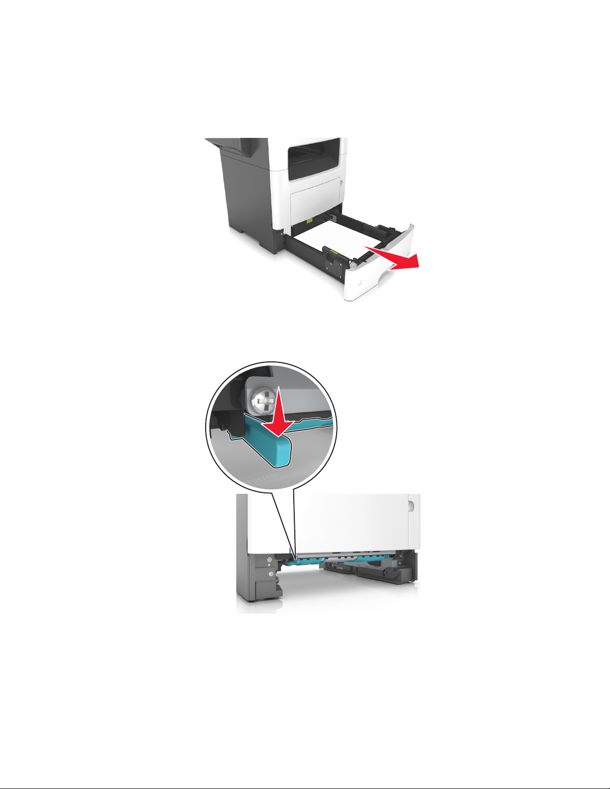
23y paper jams
[x]‑page jam, remove tray 1 to clear duplex. [23y.xx]
1 Pull out the tray completely.
7016
2 Locate the lever, and then pull it down to release the jam.
3 Firmly grasp the jammed paper on each side, and then gently pull it out.
Note: Make sure all paper fragments are removed.
Diagnostic information
60
Page 61
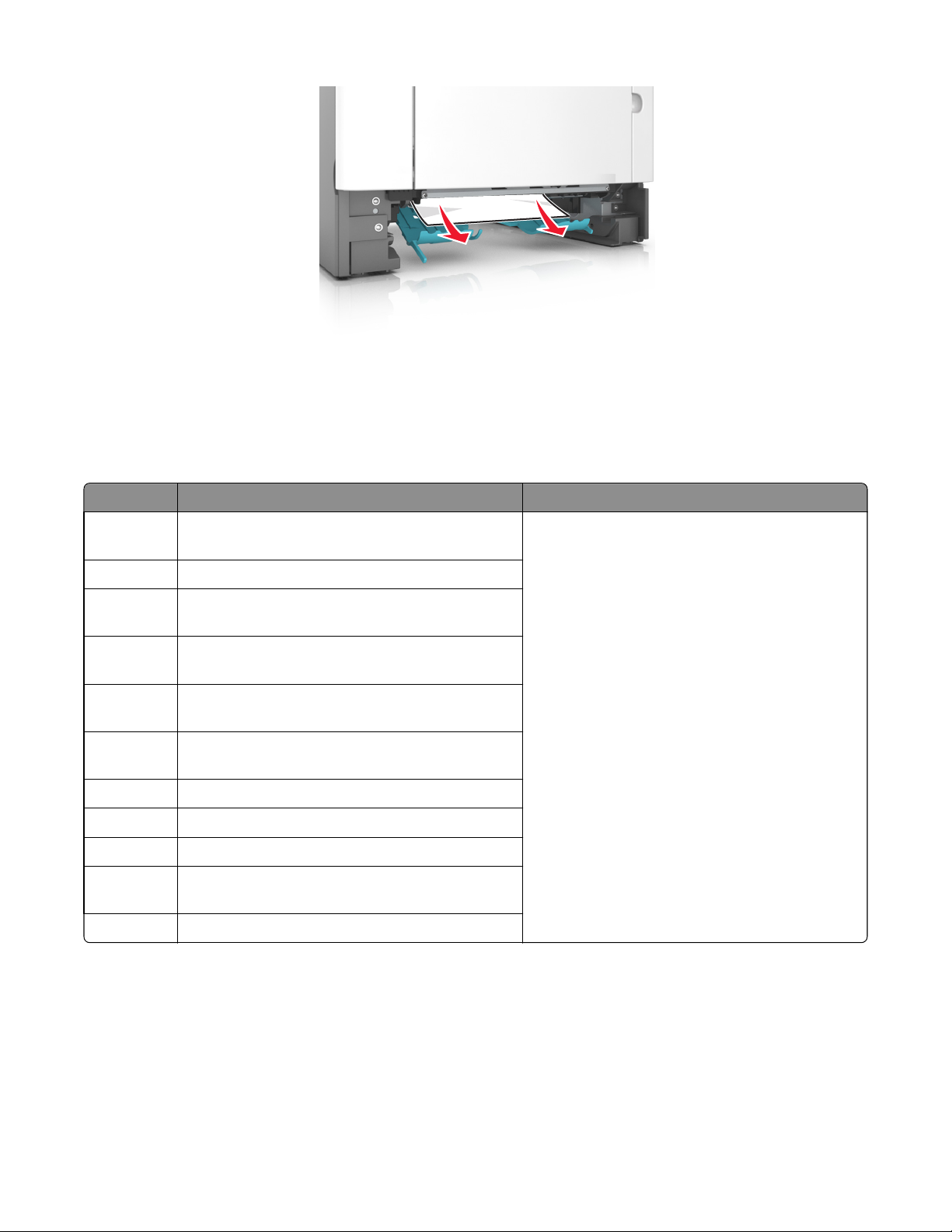
4 Insert the tray.
5 From the printer control panel, touch Done to clear the message and continue printing.
23y.xx paper jam messages
7016
Error code Description Action
230.01 Sheet covering internal duplex sensor during warm
up.
230.02 Paper jam around internal duplex.
230.03 Internal duplex sensor never made by leading edge of
page.
230.04 Page in duplexer ahead of current reversing page
never staged.
230.05 Internal duplex sensor never broke on the trailing
edge of the sheet.
230.07 Internal duplex sensor never broke from sheet ahead
of page.
230.09 Page in duplexer never picked.
230.10 Narrow page reversing into duplexer.
230.28 Bouncy duplex sensor never made.
232.03 Input sensor never detected sheet from internal
duplex path.
232.10 Feed error picking from the duplexer.
Go to “Duplex service check” on page 62.
Diagnostic information
61
Page 62

Duplex service check
Action Yes No
7016
Step 1
a Remove the rear cover.
b Check the redrive rollers for wear or damage.
Are they free of wear or damage?
Step 2
a Remove the left cover. See “Left cover removal” on page 221.
b POR into the Diagnostics menu and navigate to:
DUPLEX TESTS >Duplex Feed 1
c Check the reverse solenoid for proper operation.
Does it function properly?
Step 3
a Remove the input tray.
b From under the printer, check the duplex gear assembly and duplex
link for wear and damage.
Are the they free of wear and damage?
Step 4
From under the printer, check the duplex, belt, and roller for wear and
damage.
Go to step 2. Replace the redrive
assembly. See “Redrive
assembly removal” on
page 301.
Go to step 3. Replace the reverse
solenoid. See “Reverse
solenoid removal” on
page 230.
Go to step 4. Replace the duplex
gear assembly. See
“Duplex gear assembly
removal” on page
232.
Go to step 5. Replace the duplex.
See “Duplex removal”
on page 282.
Are they free of wear and damage?
Step 5
Go to step 6. Replace the duplex
a POR into the Diagnostics menu and navigate to:
DUPLEX TESTS >Sensor Test
b Lower the jam access cover, and toggle the duplex sensor.
Does the sensor state on the control panel change when it is toggled?
Step 6
Does the error remain?
Contact the next level
of support.
24y paper jams
[x]‑page jam, open tray [x]. [24y.xx]
1 Pull out the tray completely.
Note: The message on the printer display indicates the tray where the jammed paper is located.
sensor. See “Duplex
sensor and input
sensor removal” on
page 283.
The problem is solved.
Diagnostic information
62
Page 63

2 Firmly grasp the jammed paper on each side, and then gently pull it out.
Note: Make sure all paper fragments are removed.
7016
3 Insert the tray.
4 From the printer control panel, touch Done to clear the message and continue printing.
24y.xx paper jam messages
Error code Description Action
241.01 Paper over tray 1 pass thru sensor on warmup. Go to “Tray 1 jam service check” on page 69.
241.02 Sensor (input) early arriving jam.
241.03 Tray 1 pass thru sensor never became covered when
feeding a sheet from an option below.
241.07 Option tray 1 pass thru sensor never became
uncovered when feeding a sheet from an option
below.
241.13 The media is late reaching the sensor (input) within
the specified time from tray 1.
Diagnostic information
63
Page 64

Error code Description Action
7016
241.14 The media is late reaching the sensor (input) within
the specified time from tray 1.
241.15 Media tray 1, tray pulled jam.
241.16 The engine timed out waiting for the tray 1 to report
'ready' before the 1st pick attempt.
241.17 Page was not properly picked from tray 1. Have not
exhausted all pick retry attempts as there are sheets
committed to the paper path from below.
241.18 Failed to feed from tray 1. Exhausted all pick retries.
Paper present sensing indicates media is in the tray.
241.20 Took too long to ramp up media feeder motor in tray
1.
241.21 Media feeder motor stall in tray 1.
241.22 Media feeder motor pick motor underspeed in tray 1.
241.24 Media feeder motor stalled on the last pick attempt
in tray 1.
241.29 Tray 1 lift plate failed to make the index sensor while
elevating.
241.32 Media tray not ready.
Go to “Tray 1 jam service check” on page 69.
Go to “Tray 1 jam service check” on page 69.
Go to “Tray 1 jam service check” on page 69.
241.33 The media tray was pulled during the media pick
process.
241.41 Media feeder motor stall in tray 1. Go to “Tray 1 jam service check” on page 69.
241.42 Media feeder motor pick motor under‑speed in tray
1.
241.43 Media feeder motor stalled on the last pick attempt
in tray 1.
241.44 Motor 2 (Separator/Passthru) motor stalled.
241.45 Motor 2 (Separator/Passthru) motor PWM overflow
error (underspeed). Motor underspeed (max PWM
and motor underspeed, typical accordion jam).
241.46 Motor 2 (Separator/Passthru) motor ramp (end ramp
- did not reach speed, typical pack feed paper jam).
241.47 Motor 3 motor stalled.
241.48 Motor 3 motor PWM overflow error (underspeed).
Motor underspeed (max PWM and motor
underspeed, typical accordion jam).
241.49 Motor 3 motor ramp (end ramp - did not reach speed,
typical pack feed paper jam).
Go to “Tray 1 jam service check” on page 69.
Diagnostic information
64
Page 65

7016
Error code Description Action
242.01 Paper over tray 2 pass thru sensor on warmup. Go to “Option tray jam service check” on page 70.
242.02 Input sensor detected late feed during a pick retry
from tray 2.
242.03 Tray 2 pass thru sensor never became covered when
feeding a sheet from an option below.
242.06 Failed to feed from tray. Paper present sensing
supported and indicates media still in tray.
242.07 Option tray 2 pass thru sensor never became
uncovered when feeding a sheet from an option
below.
242.09 Tray 2 pick motor lost encoder. Go to “Option tray jam service check” on page 70.
242.11 Autocomp Pick/Lift Motor—Encoder Never Detected
in tray 2.
242.12 Motor ramp up error in tray 2.
242.13 Page to be stapled failed to feed from tray.
242.14 Sheets flushed from paper path either due to feed
error or cartridge error.
242.15 One or more trays located above the source tray 2 has
been pulled.
242.16 The engine timed out waiting for the tray 2 to report
ready before the 1st pick attempt.
242.17 Page was not properly picked from tray 2. Have not
exhausted all pick retry attempts as there are sheets
committed to the paper path from below.
242.19 Tray 2 fail to feed error. Detected while trying to pick
a sheet, and that leading edge was not detected by
tray sensor.
242.20 Took too long to ramp up dc feed motor in tray 2.
242.21 Pick motor stall in tray 2.
242.22 Tray 2 pick motor underspeed.
242.24 DC Feed autocompensator stalled on the last pick
attempt in tray 2.
242.32 Tray not ready.
242.33 Pick received but detected a tray pulled.
Go to “Option tray jam service check” on page 70.
Go to “Option tray jam service check” on page 70.
Go to “Option tray jam service check” on page 70.
242.41 Motor 1 (Pick/Lift) Elevator motor stalled.
Diagnostic information
65
Page 66

Error code Description Action
7016
242.42 Motor 1 (Pick/Lift) Elevator motor PWM overflow
error (underspeed). Motor underspeed (max PWM
and motor underspeed, typical accordion jam).
242.43 Motor 1 (Pick/Lift) motor ramp (end ramp - did not
reach speed, typical pack feed paper jam).
242.44 Motor 2 (Separator/Passthru) motor stalled.
242.45 Motor 2 (Separator/Passthru) motor PWM overflow
error (underspeed). Motor underspeed (max PWM
and motor underspeed, typical accordion jam).
242.46 Motor 2 (Separator/Passthru) motor ramp (end ramp
- did not reach speed, typical pack feed paper jam).
242.47 Motor 3 motor stalled. Go to “Option tray jam service check” on page 70.
242.48 Motor 3 motor PWM overflow error (underspeed).
Motor underspeed (max PWM and motor
underspeed, typical accordion jam).
242.49 Motor 3 motor ramp (end ramp - did not reach speed,
typical pack feed paper jam).
243.01 Paper over tray 3 pass thru sensor on warmup.
243.02 Input sensor detected late feed during a pick retry
from tray 3.
Go to “Option tray jam service check” on page 70.
Go to “Option tray jam service check” on page 70.
243.03 tray 3 pass thru sensor never became covered when
feeding a sheet from an option below.
243.06 Failed to feed from tray. Paper present sensing
supported and indicates media still in tray.
243.07 Option tray 3 pass thru sensor never became
uncovered when feeding a sheet from an option
below.
243.09 Tray 3 pick motor lost encoder. Go to “Option tray jam service check” on page 70.
243.10 Failed to feed from tray.
243.11 Autocomp Pick / Lift Motor - Encoder never detected
in tray 3.
243.12 Motor ramp up error in tray 3.
243.13 Page to be stapled failed to feed from tray. Go to “Option tray jam service check” on page 70.
243.14 Sheets flushed from paper path either due to feed
error or cartridge error.
243.15 One or more trays located above the source tray 3 has
been pulled.
243.16 The engine timed out waiting for the tray 3 to report
'ready' before the 1st pick attempt.
Diagnostic information
66
Page 67
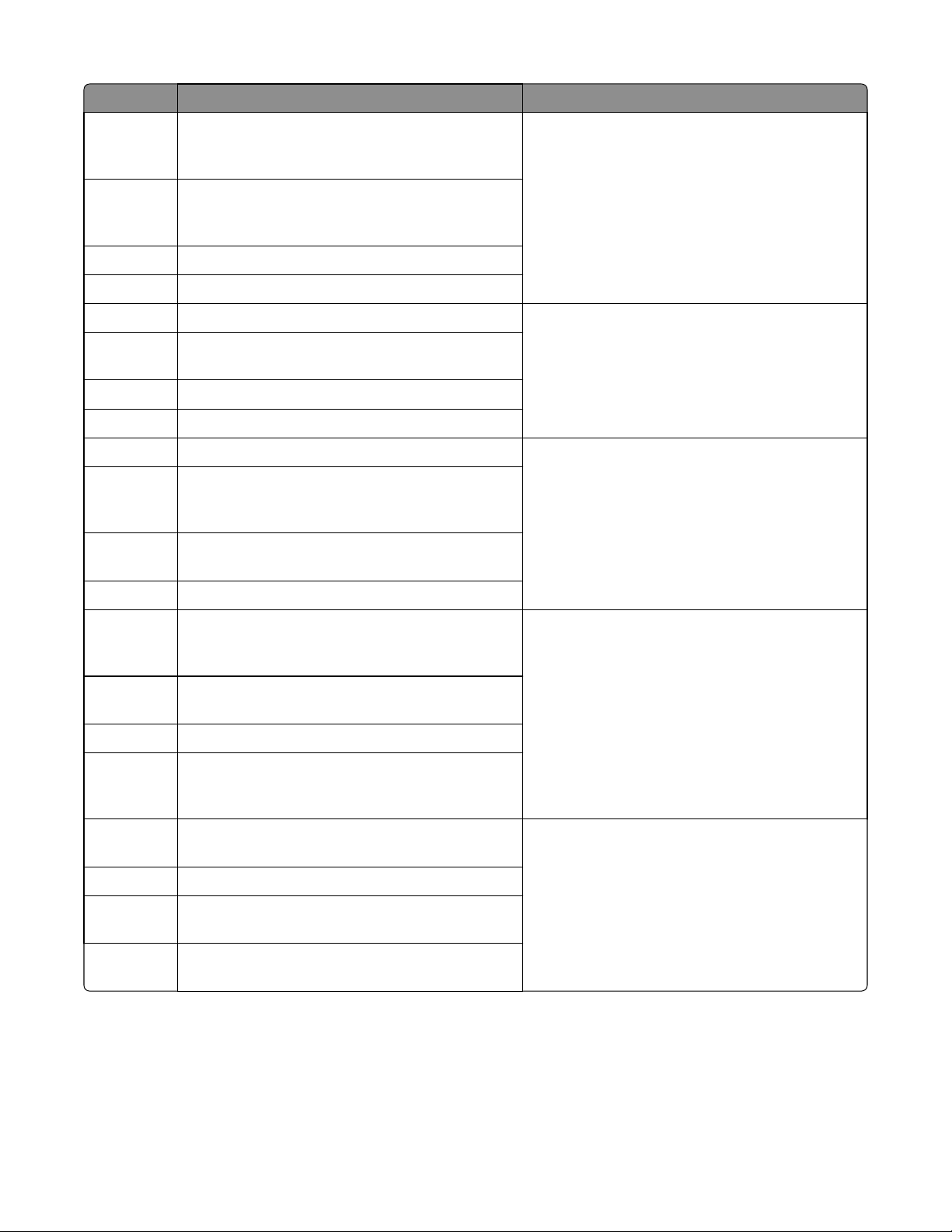
Error code Description Action
7016
243.17 Page was not properly picked from tray 3. Have not
exhausted all pick retry attempts as there are sheets
committed to the paper path from below.
243.19 Tray 3 fail to feed error. Detected while trying to pick
a sheet, and that leading edge was not detected by
tray sensor.
243.20 Took too long to ramp up dc feed motor in tray 3.
243.21 Pick motor stall in tray 3.
243.22 Tray 3 pick motor underspeed. Go to “Option tray jam service check” on page 70.
243.24 DC Feed autocompensator stalled on the last pick
attempt in tray 3.
243.32 Tray not ready.
243.33 Pick received but detected a tray pulled.
243.41 Motor 1 (Pick/Lift) Elevator motor stalled. Go to “Option tray jam service check” on page 70.
243.42 Motor 1 (Pick/Lift) Elevator motor PWM overflow
error (underspeed). Motor underspeed (max PWM
and motor underspeed, typical accordion jam).
243.43 Motor 1 (Pick/Lift) motor ramp (end ramp - did not
reach speed, typical pack feed paper jam).
Go to “Option tray jam service check” on page 70.
243.44 Motor 2 (Separator/Passthru) motor stalled.
243.45 Motor 2 (Separator/Passthru) motor PWM overflow
error (underspeed). Motor underspeed (max PWM
and motor underspeed, typical accordion jam).
243.46 Motor 2 (Separator/Passthru) motor ramp (end ramp
- did not reach speed, typical pack feed paper jam).
243.47 Motor 3 motor stalled.
243.48 Motor 3 motor PWM overflow error (underspeed).
Motor underspeed (max PWM and motor
underspeed, typical accordion jam).
243.49 Motor 3 motor ramp (end ramp - did not reach speed,
typical pack feed paper jam).
244.01 Paper over tray 4 pass thru sensor on warmup.
244.02 Input sensor detected late feed during a pick retry
from tray 4.
244.03 Tray 4 pass thru sensor never became covered when
feeding a sheet from an option below.
Go to “Option tray jam service check” on page 70.
Go to “Option tray jam service check” on page 70.
Diagnostic information
67
Page 68
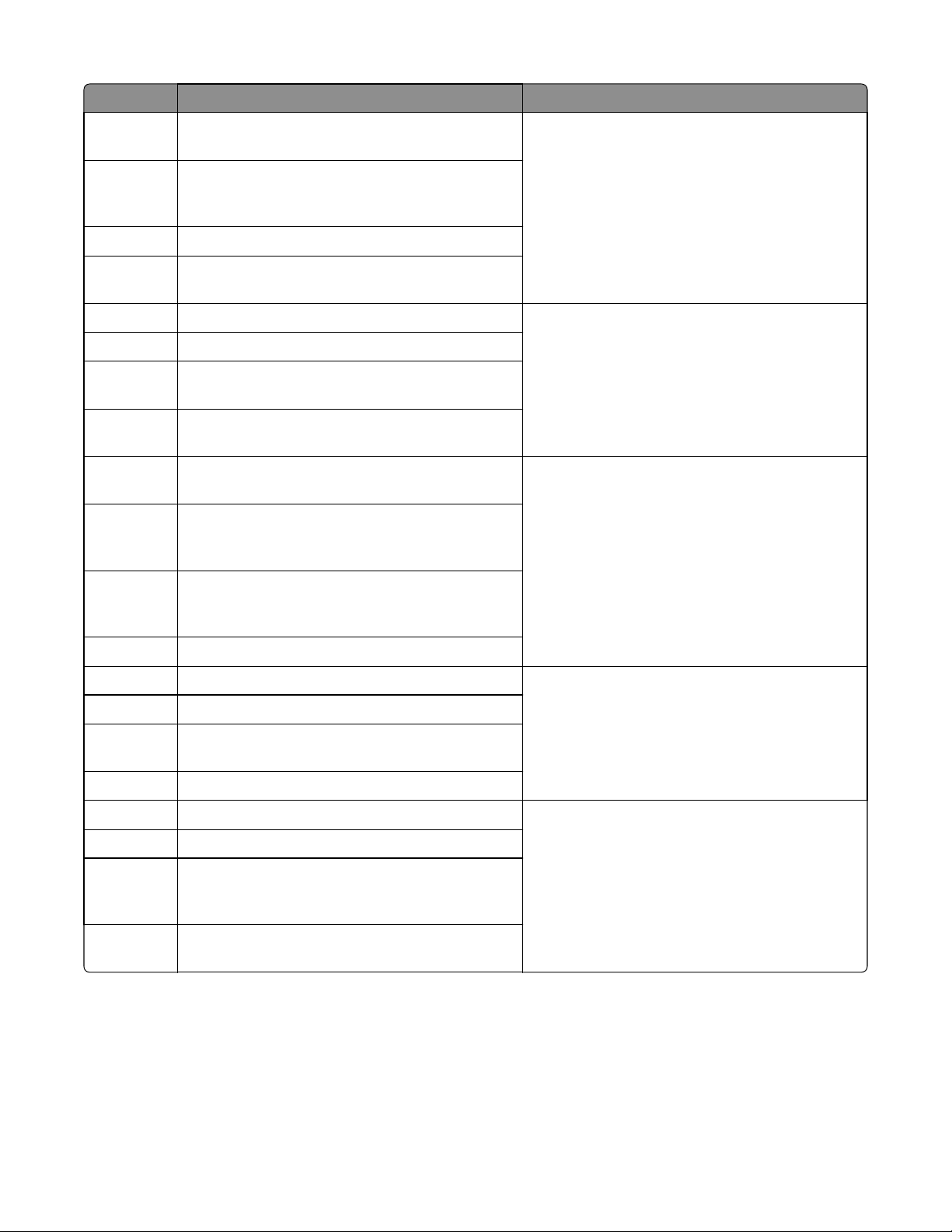
Error code Description Action
7016
244.06 Failed to feed from tray. Paper present sensing
supported and indicates media still in tray.
244.07 Option tray 4 pass thru sensor never became
uncovered when feeding a sheet from an option
below.
244.09 Tray 4 pick motor lost encoder.
244.11 Autocomp Pick / Lift Motor - Encoder Never Detected
in tray 4.
244.12 Motor ramp up error in tray 4. Go to “Option tray jam service check” on page 70.
244.13 Page to be stapled failed to feed from tray.
244.14 Sheets flushed from paper path either due to feed
error or cartridge error.
244.15 One or more trays located above the source tray 4 has
been pulled.
244.16 The engine timed out waiting for the tray 4 to report
'ready' before the 1st pick attempt.
244.17 Page was not properly picked from tray 4. Have not
exhausted all pick retry attempts as there are sheets
committed to the paper path from below.
Go to “Option tray jam service check” on page 70.
Go to “Option tray jam service check” on page 70.
244.19 Tray 4 fail to feed error. Detected while trying to pick
a sheet, and that leading edge was not detected by
tray sensor.
244.20 Took too long to ramp up dc feed motor in tray 4.
244.21 Pick motor stall in tray 4. Go to “Option tray jam service check” on page 70.
244.22 Tray 4 pick motor underspeed.
244.24 DC Feed autocompensator stalled on the last pick
attempt in tray 4.
244.32 Tray not ready.
244.33 Pick received but detected a tray pulled. Go to “Option tray jam service check” on page 70.
244.41 Motor 1 (Pick/Lift) Elevator motor stalled.
244.42 Motor 1 (Pick/Lift) Elevator motor PWM overflow
error (underspeed). Motor underspeed (max PWM
and motor underspeed, typical accordion jam).
244.43 Motor 1 (Pick/Lift) motor ramp (end ramp - did not
reach speed, typical pack feed paper jam).
Diagnostic information
68
Page 69

Error code Description Action
244.44 Motor 2 (Separator/Passthru) motor stalled. Go to “Option tray jam service check” on page 70.
244.45 Motor 2 (Separator/Passthru) motor PWM overflow
error (underspeed). Motor underspeed (max PWM
and motor underspeed, typical accordion jam).
244.46 Motor 2 (Separator/Passthru) motor ramp (end ramp
- did not reach speed, typical pack feed paper jam).
244.47 Motor 3 motor stalled.
244.48 Motor 3 motor PWM overflow error (underspeed).
Motor underspeed (max PWM and motor
underspeed, typical accordion jam).
244.49 Motor 3 motor ramp (end ramp - did not reach speed,
typical pack feed paper jam).
Tray 1 jam service check
Action Yes No
7016
Step 1
Restart the printer.
Does it fail to complete the POST sequence and display a 241.xx error?
Step 2
Check the pick tires.
Are they free of wear or damage?
Step 3
Check the separator roll assembly.
Is it free of wear or damage?
Step 4
Check the tray guides.
Are they free of wear or damage?
Step 5
a POR into the Diagnostics menu and perform a feed test:
Diagnostics Menu > I nput Tray Tests > Feed Test > Tray 1 > Continuous
b Cancel the test after five pages.
Replace the index
sensor.
Go to step 3. Replace the pick tires.
Go to step 4. Replace the separator
Go to step 5. Replace the tray insert.
Go to step 7. Go to step 6.
Go to step 2.
roll assembly. See
“Separator roll
assembly removal” on
page 328.
Does the printer successfully feed the five pages into the output bin?
Diagnostic information
69
Page 70

Action Yes No
7016
Step 6
Observe the location of the jammed paper.
Are the first page fed to the output bin, the second page jammed in the
rear door, and the third page jammed in the input tray?
Step 7
Perform a tray 1 pick/lift motor gearbox service check. See “Tray 1 pick/
lift motor gearbox service check” on page 115.
Does the error remain?
Step 8
Check the ACM assembly.
Is it free of wear or damage?
Step 9
Check the MPF gearbox
Is it free of wear or damage?
Step 10
Check the main drive gearbox
Is it free of wear or damage?
Go to step 7. Replace the trailing
edge sensor. See
“Trailing edge sensor
removal” on page
289.
Go to step 8. The problem is solved.
Go to step 9. Replace the ACM
assembly. See “ACM
assembly removal” on
page 290.
Go to step 10. Replace the MPF
gearbox. See “MPF
gearbox removal” on
page 227.
Go to step 11. Replace the main drive
gearbox. See“Main
drive gearbox
removal” on page
223.
Step 11
Does the error remain?
Contact the next level
of support.
Option tray jam service check
Action Yes No
Step 1
Restart the printer.
Does it fail to complete the POST sequence and display a 242.01 error?
Step 2
a POR into the Diagnostics menu and perform a feed test:
Diagnostics Menu > Input Tray Tests > Feed Test >
Select an option tray > Continuous
b Cancel the test after five pages.
Does the printer successfully feed the five pages into the output bin?
Step 3
Does the printer display a 242.06 error?
Replace the option
tray.
The problem is solved. Go to step 3.
Replace the ACM
assembly. See “ACM
assembly removal” on
page 330.
The problem is solved.
Go to step 2.
Go to step 4.
Diagnostic information
70
Page 71

Action Yes No
7016
Step 4
Check the pick roller assembly.
Is it free of wear or damage?
Step 5
Check the separator roll assembly.
Is it free of wear or damage?
Step 6
Check the tray guides, lift plate, and lift plate gears.
Are they free of wear or damage?
Step 7
Check the ACM assembly.
Is it free of wear or damage?
Step 8
POR into the Diagnostics menu and perform a feed test:
Diagnostics Menu > Input Tray Tests > Feed Test > Select an option tray
Go to step 5. Replace the pick roller
assembly. See “Pick
roller removal” on
page 328.
Go to step 6. Replace the separator
roll assembly. See
“Separator roll
assembly removal” on
page 328.
Go to step 7. Replace the tray insert.
Go to step 8. Replace the ACM
assembly. See “ACM
assembly removal” on
page 330.
Go to step 9. Replace the option
tray.
Does the pick/lift motor gearbox pass the test?
Step 9
Does the error remain?
Contact the next level
of support.
The problem is solved.
25y paper jams
[x]‑page jam, clear manual feeder. [25y.xx]
1 From the multipurpose feeder, firmly grasp the jammed paper on each side, and then gently pull it out.
Note: Make sure all paper fragments are removed.
Diagnostic information
71
Page 72

7016
2 Flex the sheets back and forth to loosen them, and then fan them. Do not fold or crease the paper. Straighten the
edges on a level surface.
3 Reload paper into the multipurpose feeder.
Note: Make sure the paper guide lightly rests against the edge of the paper.
4 From the printer control panel, touch Done to clear the message and continue printing.
Diagnostic information
72
Page 73
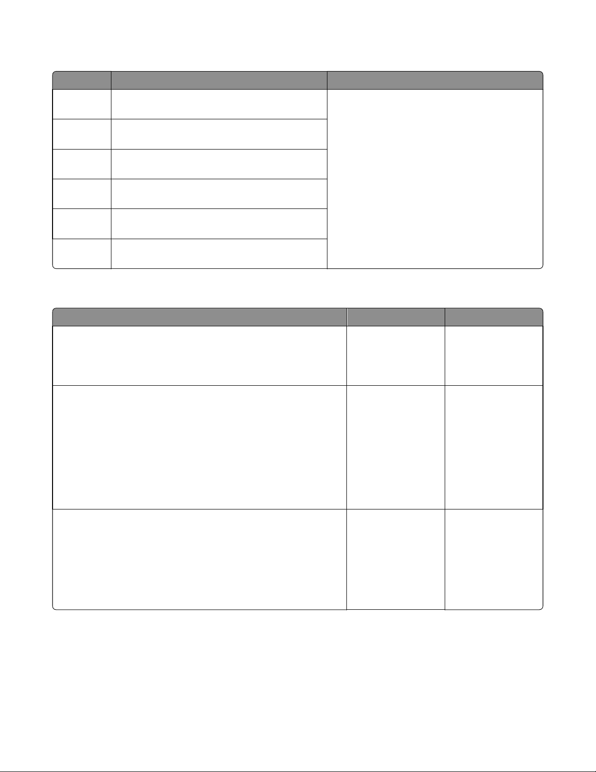
25y.xx paper jam messages
Error code Description Action
7016
250.06 Input sensor did not detect sheet picked from MPF.
No other sheets should be in the path.
250.10 Input sensor did not detect sheet picked from MPF.
No other sheets should be in the path.
250.13 Input sensor did not detect sheet picked from MPF.
Sheet also last page of stapled job.
250.14 Input sensor did not detect sheet picked from MPF.
Other sheets should have been flushed.
250.17 Input sensor did not detect sheet picked from MPF.
No other sheets should be in the path.
250.18 Input sensor did not detect sheet picked from
MPF. Other sheets could be in the path.
Go to “MPF service check” on page 73.
MPF service check
Action Yes No
Step 1
Check the springs, links, and tray guides on the MPF assembly for damage.
Are they free of damage?
Go to step 2. Replace the MPF
assembly. See “MPF
tray removal” on
page 269.
Step 2
a Make sure the MPF sensor cable is properly connected to the
controller board.
b POR into the Diagnostics menu and perform a sensor test:
Diagnostics Menu > Input Tray Tests > Sensor Tests > Multi‑Purpose
Feeder
Does the sensor state on the control panel display change when it is
toggled?
Step 3
Make sure the MPF pick roller and separator pad are free of debris. Check
both for wear or damage.
Are they free of damage?
Go to step 3. Replace the front input
guide. See “Front input
guide removal” on
page 276.
Go to step 4. Replace the MPF pick
roller and separator
pad. See “MPF pick
roller removal” on
page 271 and
“Separator pad
removal” on page
278.
Diagnostic information
73
Page 74
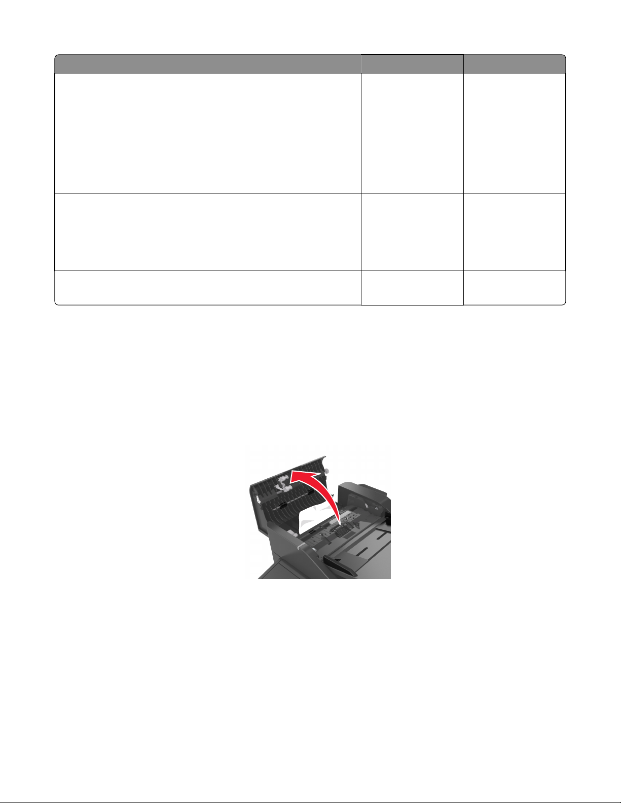
Action Yes No
7016
Step 4
a Remove the left cover.
b POR into the Diagnostics menu and perform a feed test:
Diagnostics Menu > Input Tray Tests > Feed Tests > Multi‑Purpose
Feeder
c Check the MPF solenoid for proper operation.
Does it function properly?
Step 5
a Make sure the MPF gearbox is free of debris.
b Check the gears and spring of the MPF gearbox for wear or damage.
Are they free of damage?
Step 6
Does the error remain?
28y paper jams
[x]‑page jam, open automatic feeder top cover. [28y.xx]
Go to step 5. Replace the MPF
solenoid. See “MPF
solenoid removal” on
page 225.
Go to step 6. Replace the MPF
gearbox. See “MPF
gearbox removal” on
page 227.
Contact the next level
of support.
The problem is solved.
1 Remove all original documents from the ADF tray.
Note: The message is cleared when the pages are removed from the ADF tray.
2 Open the ADF cover.
3 Firmly grasp the jammed paper on each side, and then gently pull it out.
Note: Make sure all paper fragments are removed.
4 Close the ADF cover.
5 Straighten the edges of the original documents, then load the documents into the ADF, and then adjust the paper
guide.
6 From the printer control panel, touch Done to clear the message and continue printing.
Diagnostic information
74
Page 75

28y.xx paper jams
28x.xx paper jams
Error code Description Action
7016
280.06 Paper Missing—Posted when paper is
removed from input tray after job is initiated.
282.01 ADF Static Jam—Interval Sensor active at
POR time.
282.03 ADF Pickup Jam—LE of paper does not reach
Interval Sensor in time.
282.05 ADF Long Page—TE never clears interval
sensor (but 1st Scan Sensor and Exit Sensor
are both active).
283.01 ADF Static Jam—1st Scan Sensor active at
POR time.
283.03 ADF Feed Jam—LE of paper does not reach
1st Scan Sensor in time.
283.05 1st Scan Sensor Jam—TE never clears 1st
Scan Sensor.
286.02 ADF Backfeed—Page(s) in the exit area
accidentally gets pulled into the reverse
path.
Ensure that the ADF document sensor is in the proper position
and clear of dust and deris. Retry the job. If the error recurs, then
see “ADF paper jam service check” on page 146.
Remove the sheet of paper rom the ADF. Retry the job. If the
error recurs, then see “ADF paper jam service check” on
page 146.
Remove the sheet of paper rom the ADF. Check the media
weight, Heavier paper should not be used. Make the stack of
documents in the tray smaller. Ensure that the media is not being
shoved into the tray. Retry the job. If the error recurs, then see
“ADF paper jam service check” on page 146.
Inspect the ADF paper path for paper fragments. Restart the
MFP. If the error recurs, then see “ADF paper jam service check”
on page 146.
Remove the sheet of paper rom the ADF. Retry the job. If the
error recurs, then see “ADF paper jam service check” on
page 146.
Remove the sheet of paper rom the ADF. Retry the job. If the
error recurs, then see “ADF paper jam service check” on
page 146.
Too many sheets of paper in the ADF exit bin. Remove the sheets
from the ADF exit bin.
286.03 ADF Backside Feed Jam—LE does not reach
the multi-purpose Interval Sensor in time
when page routed through reverse area.
286.05 ADF Backside Jam—TE does not reach the
multi-purpose Interval Sensor in time when
page routed through reverse area.
Remove the sheet of paper from the ADF. Retry the job. If the
error recurs, then see “ADF paper jam service check” on
page 146.
29y.xx paper jams
29x.xx paper jams
Error code Description Action
290.11 ADF Cover Open Jam—Posted when ADF top
cover is opened during ADF job.
Diagnostic information
Close the cover. If the error recurs, then perform the ADF cover
open service check
75
Page 76

45y paper jams
[x]-page jam, remove all pages from the output bin. Leave paper in bin. [45y.xx]
Paper jam in the finisher bin
1 Empty the standard bin.
7016
2 Move the tamper arms to the sides.
3 Remove all jammed pages from inside the access areas.
Note: Make sure all paper fragments are removed.
Diagnostic information
76
Page 77
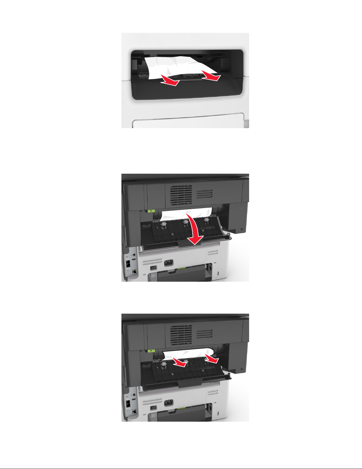
4 If necessary, touch Done from the printer control panel to clear the message and continue printing.
Paper jam in the finisher rear door
1 Open the finisher rear door.
7016
2 Firmly grasp the jammed paper on each side, and then gently pull it out.
Note: Make sure all paper fragments are removed.
Diagnostic information
77
Page 78
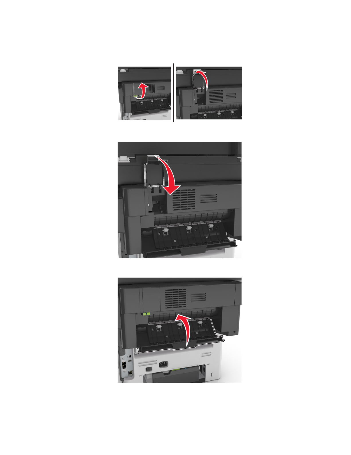
3 Open the finisher trap door, remove any paper fragments inside the trap door.
Note: After removing any jammed paper in the finisher bin or in the finisher rear door, open the trap door to
remove any paper fragments.
4 Close the trap door.
7016
5 Close the finisher rear door.
6 If necessary, touch Done from the printer control panel to clear the message and continue printing.
Diagnostic information
78
Page 79
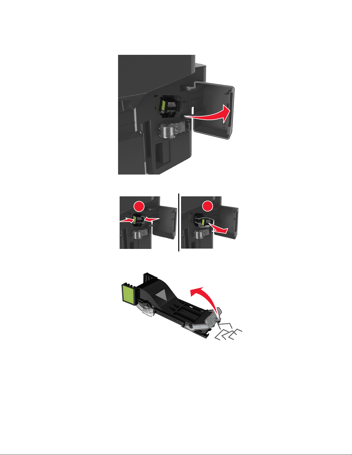
Staple jam in the finisher
1 Open the staple access door.
7016
2 Pull out the staple cartridge from the finisher.
1
3 Lift the staple guard, and then remove any jammed or loose staples.
2
Diagnostic information
79
Page 80
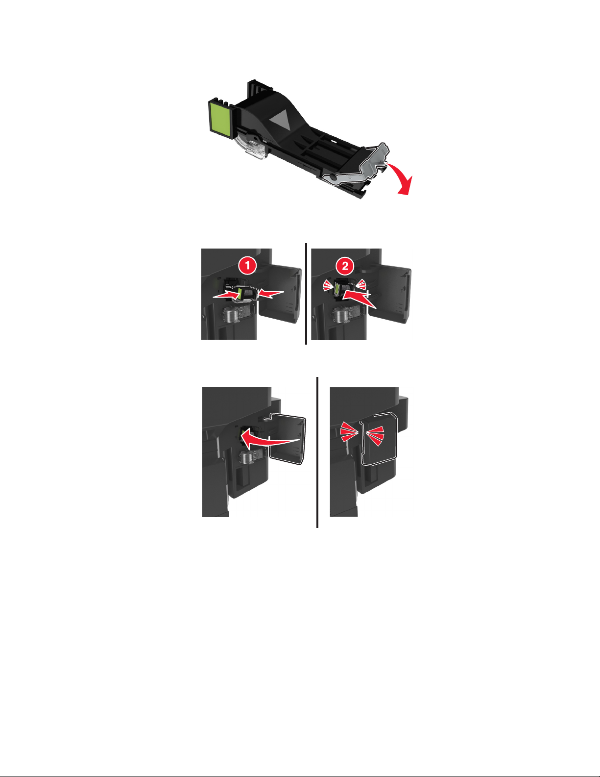
4 Press down the staple guard until it clicks into place.
5 Insert stapler cartridge back into the finisher until it clicks into place.
7016
6 Close the staple access door.
7 If necessary, touch Done from the printer control panel to clear the message and continue printing.
Diagnostic information
80
Page 81

[x]-page jam, remove all pages from the finisher’s accumulator. Leave paper in bin. [45y.xx]
Paper jam in the finisher bin
1 Empty the standard bin.
2 Move the tamper arms to the sides.
7016
3 Remove all jammed pages from inside the access areas.
Note: Make sure all paper fragments are removed.
4 If necessary, touch Done from the printer control panel to clear the message and continue printing.
Diagnostic information
81
Page 82

Paper jam in the finisher rear door
1 Open the finisher rear door.
2 Firmly grasp the jammed paper on each side, and then gently pull it out.
Note: Make sure all paper fragments are removed.
7016
3 Open the finisher trap door, and then remove any paper fragments from inside the trap door.
Note: After removing any jammed paper in the finisher rear door, open the trap door to remove any paper
fragments.
Diagnostic information
82
Page 83

4 Close the trap door.
5 Close the finisher rear door.
7016
6 If necessary, touch Done from the printer control panel to clear the message and continue printing.
Diagnostic information
83
Page 84

45y.xx paper jams
Error code Description Action
7016
451.01 Media remains detected by the sensor (stapler pass
through) after power on.
451.03 The media fed did not reach the sensor (stapler pass
through).
451.05 The media while feeding remains detected by the
sensor (stapler pass through).
451.09 Never received Page In Output from the staple
finisher
451.10 Invalid Page ID returned by the staple finisher
451.41 Staple finisher interface/main motor stalled
451.42 Staple finisher interface/main motor did not reach the
required speed.
451.43 Took too long to ramp up interface/main motor in the
staple finisher
452.73 Staple finisher left tamper failed to leave its home
position
452.74 Staple finisher left tamper failed to reach its home
position
453.75 Staple finisher right tamper failed to leave its home
position
Go to “Finisher jam service check” on page 85.
Go to “Tamper motor jam service check” on
page 87.
453.76 Staple finisher right tamper failed to reach its home
position
454.41 Staple finisher ejector motor stalled Go to “Ejector jam service check” on page 85.
454.42 Staple finisher ejector motor did not reach the
required speed.
454.43 Took too long to ramp up ejector motor in the staple
finisher
454.53 Staple finisher ejector motor went over the normal
speed.
454.77 Staple finisher ejector failed to leave its home position
454.78 Staple finisher ejector failed to reach its home
position
Diagnostic information
84
Page 85
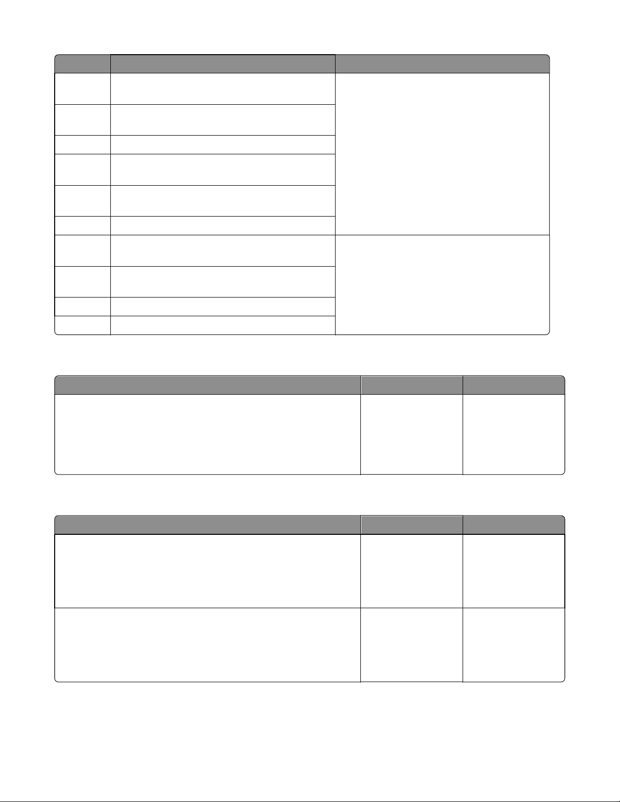
Error code Description Action
7016
456.03 Failure to staple—media did not reach the stapler
throat
456.07 Paper jam—media remains detected in the stapler
throat
456.83 Stapler unit homing failure
456.84 Staple unit jam while stapling—media remains
detected by the home position sensor
456.85 Staple unit jam while stapling—unable to return to
home position
456.86 Stapler cartridge empty—unable to staple
457.87 Staple failed to prime the staple wire after a stapling
operation
457.88 Staple failed to prime the staple wire after a homing
operation
457.89 Staple failed to prime after a stapling operation
457.90 Staple failed to prime before a stapling operation
Ejector jam service check
Go to “Stapler carriage jam service check” on
page 86.
Go to “Stapler priming jam service check” on
page 87.
Action Yes No
Open the stapler service cover and check the ejector motor cable
connection on the stapler controller board.
Is it properly connected?
If the error persists,
then replace the staple
finisher option. Go to
“Staple finisher option
removal” on page
333.
Finisher jam service check
Action Yes No
Step 1
POR the machine.
Does the machine fail to complete the POR sequence or does the same
error persist?
Step 2
Open the stapler service cover and check all connectors on the stapler
controller board.
Are all of them properly connected?
Go to step 2. Go to step 3.
Go to step 3. Reseat all connections
Reseat the ejector
motor connector.
on the stapler
controller board.
Diagnostic information
85
Page 86

Action Yes No
7016
Step 3
Enter Diagnostic mode and navigate to:
FINISHER TESTS > Sensor Test
Select Pass and Media.
Does the status shown on the control panel change each time the sensor
is toggled?
Step 4
Check the paper path of the stapler for obstructions.
Is it free of obstructions?
Go to step 4. Replace the sensor
If the error persists,
then replace the staple
finisher option. Go to
“Staple finisher option
removal” on page
333.
Stapler carriage jam service check
Action Yes No
Step 1
POR the machine.
Does the machine fail to complete the POR sequence or does the same
error persist?
Go to step 2. Go to step 5.
(stapler pass through).
Go to “Sensor (stapler
pass through)
removal” on page
363.
Remove all
obstructions along the
paper path.
Step 2
Open the stapler service cover and check all connectors on the stapler
controller board.
Are all of them properly connected?
Step 3
Replace the stapler carriage assembly. See “Stapler carriage assembly
removal” on page 338.
Does the error remain?
Step 4
Replace the stapler controller board. See “Stapler controller PCBA
removal” on page 347.
Does the error remain?
Step 5
Enter Diagnostic mode and navigate to:
FINISHER TESTS > Feed Test
Open the rear door and observe the position of the leading edge of the
media.
Go to step 3. Reseat all connections
on the stapler
controller board.
Go to step 4. The problem is solved.
Go to step 5. The problem is solved.
If the error persists,
then replace the staple
finisher option. Go to
“Staple finisher option
removal” on page
333.
Go to step 6.
Does the leading edge pass through the sensor (pass through)?
Diagnostic information
86
Page 87

Action Yes No
7016
Step 6
Enter Diagnostic mode and navigate to:
FINISHER TESTS > Sensor Test
Select Pass and Media.
Does the status shown on the control panel change each time the sensor
is toggled?
If the error persists,
then replace the staple
finisher option. Go to
“Staple finisher option
removal” on page
333.
Stapler priming jam service check
Action Yes No
Step 1
POR the machine.
Does the machine fail to complete the POR sequence or does the same
error persist?
Step 2
Open the stapler service cover and check all connectors on the stapler
controller board.
Are all of them properly connected?
Go to step 2. Go to step 3.
Go to step 3. Reseat all connections
Replace the sensor
(stapler pass through).
Go to “Sensor (stapler
pass through)
removal” on page
363.
on the stapler
controller board.
Step 3
Replace the stapler carriage assembly. See “Stapler carriage assembly
removal” on page 338.
Does the error remain?
Step 4
Replace the stapler controller board. See “Stapler controller PCBA
removal” on page 347.
Does the error remain?
Go to step 4. The problem is solved.
Replace the staple
finisher option. Go to
“Staple finisher option
removal” on page
333.
Tamper motor jam service check
Action Yes No
Step 1
Check the following:
• Manually move the left and right tamper wings and check if they can
move freely.
• Check the tamper belt for damage.
Go to step 2. Replace the staple
The problem is solved.
finisher option. Go to
“Staple finisher option
removal” on page
333.
Are the above components ok?
Diagnostic information
87
Page 88
Action Yes No
7016
Step 2
Enter Diagnostic mode and navigate to:
FINISHER TESTS > Unit Test
Select Tamper.
Does the device pass the test?
Step 3
Open the stapler service cover and check the tamper motor connections
on the stapler controller board.
Are they properly connected?
Step 4
Replace the tamper motor. See “Stapler left tamper motor removal” on
page 347 or “Stapler right tamper motor removal” on page 348.
Does the error remain?
Step 5
Replace the stapler controller board. See “Stapler controller PCBA
removal” on page 347.
Does the error remain?
Go to step 3. Replace the staple
finisher option. Go to
“Staple finisher option
removal” on page
333.
Go to step 4. Reseat the tamper
motor connectors.
Go to step 5. The problem is solved.
Replace the staple
finisher option. Go to
“Staple finisher option
removal” on page
333.
The problem is solved.
Understanding the printer messages
Cartridge, imaging unit mismatch [41.xy]
Install a toner cartridge that matches the region number of the printer. x indicates the value of the printer region. y
indicates the value of the cartridge region. x and y can have the following values:
List of printer and toner cartridge regions
Region number Region
0Global
1 United States, Canada
2 European Economic Area (EEA), Switzerland
3 Asia Pacific, Australia, New Zealand
4 Latin America
5 Africa, Middle East, rest of Europe
9Invalid region
Diagnostic information
88
Page 89

7016
Notes:
• The x and y values are the .xy of the error code shown on the printer control panel.
• The x and y values must match for printing to continue.
Cartridge low [88.xy]
You may need to order a replacement toner cartridge. If necessary, touch Continue on the printer control panel to
clear the message and continue printing.
Cartridge nearly low [88.xy]
If necessary, touch Continue on the printer control panel to clear the message and continue printing.
Cartridge very low, [x] estimated pages remain [88.xy]
You may need to replace the toner cartridge very soon. For more information, see the “Replacing supplies” section of
the User’s Guide.
If necessary, touch Continue on the printer control panel to clear the message and continue printing.
Change [paper source] to [custom type name] load [orientation]
Try one or more of the following:
• Load the correct size and type of paper in the tray, then specify the paper size and type in the Paper menu on the
printer control panel, and then touch Finished changing paper.
• Touch Reset active bin to reset the active tray for a linked set of trays.
• Cancel the print job.
Change [paper source] to [custom string] load [orientation]
Try one or more of the following:
• Load the correct size and type of paper in the tray, then specify the paper size and type in the Paper menu on the
printer control panel, and then touch Finished changing paper.
• Touch Reset active bin to reset the active tray for a linked set of trays.
• Cancel the print job.
Change [paper source] to [paper size] load [orientation]
Try one or more of the following:
• Load the correct size and type of paper in the tray, then specify the paper size and type in the Paper menu on the
printer control panel, and then touch Finished changing paper.
• Touch Reset active bin to reset the active tray for a linked set of trays.
• Cancel the print job.
Diagnostic information
89
Page 90

7016
Change [paper source] to [paper type] [paper size] load [orientation]
Try one or more of the following:
• Load the correct size and type of paper in the tray, then specify the paper size and type in the Paper menu on the
printer control panel, and then touch Finished changing paper.
• Touch Reset active bin to reset the active tray for a linked set of trays.
• Cancel the print job.
Check tray [x] connection
Try one or more of the following:
• Turn off the printer, and then turn it back on.
If the error occurs a second time, then:
1 Turn off the printer.
2 Unplug the power cord from the electrical outlet.
3 Remove the indicated tray.
4 Reattach the tray.
5 Connect the power cord to a properly grounded electrical outlet.
6 Turn the printer back on.
If the error occurs again, then:
1 Turn off the printer.
2 Unplug the power cord from the electrical outlet.
3 Remove the tray.
4 Contact customer support.
• From the printer control panel, touch Continue to clear the message and resume the job.
Close front door
Close the front door of the printer.
Close flatbed cover and load originals if restarting job [2yy.xx]
Try one or more of the following:
• Touch Scan from automatic feeder to continue scanning from the ADF immediately after the last successful scan
job.
• Touch Scan from flatbed to continue scanning from the scanner glass immediately after the last successful scan
job.
• Touch Finish job without further scanning to end the last successful scan job.
Note: This does not cancel the scan job. All successfully scanned pages will be processed further for copying,
faxing, or e-mailing.
• Touch Cancel job to clear the message and cancel the scan job.
Diagnostic information
90
Page 91

Complex page, some data may not have printed [39]
Try one or more of the following:
• From the printer control panel, touch Continue to ignore the message and continue printing.
• Cancel current print job.
• Install additional printer memory.
Configuration change, some held jobs were not restored [57]
Held jobs are invalidated because of the following possible changes in the printer:
• The printer firmware has been updated.
• The tray for the print job has been removed.
• The print job is sent from a flash drive that is no longer attached to the USB port.
• The printer hard disk contains print jobs that were stored when the hard disk was installed in a different printer
model.
From the printer control panel, touch Continue to clear the message.
7016
Defective flash detected [51]
Try one or more of the following:
• Replace the defective flash memory card.
• From the printer control panel, touch Continue to ignore the message and continue printing.
• Cancel the current print job.
Disk full [62]
Try one or more of the following:
• From the printer control panel, touch Continue to clear the message and continue processing.
• Delete fonts, macros, and other data stored in the printer hard disk.
• Install a printer hard disk with larger capacity.
Disk must be formatted for use in this device
From the printer control panel, touch Format disk to format the printer hard disk and clear the message.
Note: Formatting deletes all the files stored in the printer hard disk.
Disk near full. Securely clearing disk space.
Try one or more of the following:
• Touch Continue to clear the message and continue printing.
• Delete fonts, macros, and other data stored on the printer hard disk.
• Install a hard disk with higher capacity.
Diagnostic information
91
Page 92

Error reading USB drive. Remove USB.
An unsupported USB device is inserted. Remove the USB device, and then insert a supported one.
Error reading USB hub. Remove hub.
An unsupported USB hub has been inserted. Remove the USB hub, and then install a supported one.
Fax memory full
From the printer control panel, touch Continue to clear the message.
Fax partition inoperative. Contact system administrator.
Try one or more of the following:
• From the printer control panel, touch Continue to clear the message.
• Turn off the printer, and then turn it back on. If the message appears again, then contact your system support
person.
7016
Fax server 'To Format' not set up. Contact system administrator.
Try one or more of the following:
• From the printer control panel, touch Continue to clear the message.
• Complete the Fax Server setup. If the message appears again, then contact your system support person.
Fax Station Name not set up. Contact system administrator.
Try either of the following:
• From the printer control panel, touch Continue to clear the message.
• Complete the Analog Fax setup. If the message appears again after completing the setup, then contact your system
support person.
Fax Station Number not set up. Contact system administrator.
Try one or more of the following:
• From the printer control panel, touch Continue to clear the message.
• Complete the Analog Fax setup. If the message appears again after completing the setup, then contact your system
support person.
Imaging unit low [84.xy]
You may need to order a replacement imaging unit. If necessary, select Continue on the printer control panel to clear
the message and continue printing.
Diagnostic information
92
Page 93

7016
Imaging unit nearly low [84.xy]
If necessary, touch Continue on the printer control panel to clear the message and continue printing.
Imaging unit very low, [x] estimated pages remain [84.xy]
You may need to replace the imaging unit very soon. For more information, see the “Replacing supplies” section of the
User’s Guide.
If necessary, touch Continue on the printer control panel to clear the message and continue printing.
Incompatible tray [x] [59]
Try one or more of the following:
• Remove the indicated tray.
• From the printer control panel, touch Continue to clear the message and continue printing without using the
indicated tray.
Incorrect paper size, open [paper source] [34]
Try one or more of the following:
• Load the correct size and type of paper in the tray, and then specify the paper size and type in the Paper menu on
the printer control panel.
• Make sure the correct paper size and type are specified in Print Properties or the Print dialog settings.
• Check if the paper size is correctly set. For example, if MP Feeder Size is set to Universal, then make sure the paper
is large enough for the data being printed.
• Check the length and width guides and make sure the paper is loaded properly in the tray.
• From the printer control panel, touch Continue to clear the message and print using a different tray.
• Cancel the print job.
Insufficient memory to collate job [37]
Try one or more of the following:
• From the printer control panel, touch Continue to print the part of the job already stored and begin collating the
rest of the print job.
• Cancel the current print job.
Insufficient memory for Flash Memory Defragment operation [37]
Try one or more of the following:
• From the printer control panel, touch Continue to stop the defragmentation and continue printing.
• Delete fonts, macros, and other data in the printer memory.
• Install additional printer memory.
Diagnostic information
93
Page 94

7016
Insufficient memory, some Held Jobs were deleted [37]
From the printer control panel, touch Continue to clear the message.
Insufficient memory, some held jobs will not be restored [37]
Try one or more of the following:
• From the printer control panel, touch Continue to clear the message.
• Delete other held jobs to free up additional printer memory.
Insufficient memory to support Resource Save feature [35]
Install additional printer memory or touch Continue to disable Resource Save, clear the message, and continue printing.
Load [paper source] with [custom type name] [paper orientation]
Try one or more of the following:
• Load the tray or feeder with the correct size and type of paper.
• To use the tray with the correct paper size or type, touch Finished loading paper on the printer control panel.
Note: If the printer detects a tray that has the correct paper size and type, then it feeds from that tray. If the
printer cannot detect a tray that has the correct paper size and type, then it prints from the default paper
source.
• Cancel the current job.
Load [paper source] with [custom string] [paper orientation]
Try one or more of the following:
• Load the indicated tray or feeder with the correct size and type of paper.
• To use the tray with the correct paper size or type, touch Finished loading paper on the printer control panel.
Note: If the printer finds a tray that has the correct paper size and type, then it feeds from that tray. If the
printer cannot find a tray with the correct paper type and size, then it prints from the default paper source.
• Cancel the current job.
Load [paper source] with [paper size] [paper orientation]
Try one or more of the following:
• Load the specified tray or feeder with the correct size of paper.
• To use the tray or feeder with the correct size of paper, touch Finished loading paper on the printer control panel.
Note: If the printer finds a tray or feeder that has the correct size of paper, then it feeds from that tray or
feeder. If the printer cannot find a tray or feeder with the correct size of paper, then it prints from the default
paper source.
• Cancel the current job.
Diagnostic information
94
Page 95

7016
Load [paper source] with [paper type] [paper size] [paper orientation]
Try one or more of the following:
• Load the specified tray or feeder with the correct size and type of paper.
• To use the tray or feeder with the correct size and type of paper, touch Finished loading paper on the printer control
panel.
Note: If the printer finds a tray or feeder that has the correct size and type of paper, then it feeds from that tray
or feeder. If the printer cannot find a tray or feeder with the correct size and type of paper, then it prints from
the default paper source.
• Cancel the current job.
Load Manual Feeder with [custom type name] [paper orientation]
Try one or more of the following:
• Load the feeder with the correct size and type of paper.
• From the printer control panel, touch Prompt each page, paper loaded or Do not prompt, paper loaded to clear
the message and continue printing.
• From the printer control panel, touch Automatically select paper to use the paper loaded in the tray.
• Cancel the print job.
Load Manual Feeder with [custom string] [paper orientation]
Try one or more of the following:
• Load the feeder with the correct size and type of paper.
• From the printer control panel, touch Prompt each page, paper loaded or Do not prompt, paper loaded to clear
the message and continue printing.
• From the printer control panel, touch Automatically select paper to use the paper loaded in the tray.
• Cancel the print job.
Load Manual Feeder with [paper size] [paper orientation]
Try one or more of the following:
• Load the feeder with the correct size of paper.
• From the printer control panel, touch Prompt each page, paper loaded or Do not prompt, paper loaded to clear
the message and continue printing.
• From the printer control panel, touch Automatically select paper to use the paper loaded in the tray.
• Cancel the print job.
Load Manual Feeder with [paper type] [paper size] [paper orientation]
Try one or more of the following:
• Load the feeder with the correct size and type of paper.
• From the printer control panel, touch Prompt each page, paper loaded or Do not prompt, paper loaded to clear
the message and continue printing.
Diagnostic information
95
Page 96

7016
• From the printer control panel, touch Automatically select paper to use the paper loaded in the tray.
• Cancel the print job.
Maintenance kit low [80.xy]
You may need to order a maintenance kit. For more information, contact customer support at
http://support.lexmark.com or your service representative. If necessary, touch Continue to clear the message and
continue printing.
Maintenance kit nearly low [80.xy]
For more information, contact customer support at http://support.lexmark.com or your service representative. If
necessary, touch Continue to clear the message and continue printing.
Maintenance kit very low, [x] estimated pages remain [80.xy]
You may need to replace the maintenance kit very soon. For more information, contact customer support at
http://support.lexmark.com or your service representative. If necessary, touch Continue to clear the message and
continue printing.
Memory full [38]
Try one or more of the following:
• From the printer control panel, touch Cancel job to clear the message.
• Install additional printer memory.
Memory full, cannot print faxes
From the printer control panel, touch Continue to clear the message without printing. Held faxes attempt to print after
the printer is restarted.
Memory full, cannot send faxes
1 From the printer control panel, touch Continue to clear the message and cancel the fax job.
2 Try one or more of the following:
• Reduce the fax resolution, and then resend the fax job.
• Reduce the number of pages in the fax, and then resend the fax job.
Network [x] software error [54]
Try one or more of the following:
• From the printer control panel, touch Continue to continue printing.
• Turn off the printer, wait for about 10 seconds, and then turn the printer back on.
• Update the network firmware in the printer or print server. For more information, contact customer support.
Diagnostic information
96
Page 97

7016
No analog phone line connected to modem, fax is disabled.
Connect the printer to an analog phone line.
Non‑Lexmark [supply type], see User’s Guide [33.xy]
Note: The supply type can be a toner cartridge or the imaging unit.
The printer has detected a non‑Lexmark supply or part installed in the printer.
Your Lexmark printer is designed to function best with genuine Lexmark supplies and parts. Use of third-party supplies
or parts may affect the performance, reliability, or life of the printer and its imaging components.
All life indicators are designed to function with Lexmark supplies and parts, and may deliver unpredictable results if
third-party supplies or parts are used. Imaging component usage beyond the intended life may damage your Lexmark
printer or associated components.
Warning—Potential Damage: Use of third-party supplies or parts can affect warranty coverage. Damage caused by
the use of third-party supplies or parts may not be covered by the warranty.
To accept any and all of these risks, and to proceed with the use of non-genuine supplies or parts in your printer, press
and hold
and # on the prin ter control panel simultaneously for 15 seconds to clear the message and continue printing.
If you do not wish to accept these risks, then remove the third-party supply or part from your printer, and then install
a genuine Lexmark supply or part.
Note: For the list of supported supplies, see the “Ordering supplies” section of the User's Guide or visit
www.lexmark.com.
Not enough free space in flash memory for resources [52]
Try one or more of the following:
• From the printer control panel, touch Continue to clear the message and continue printing.
• Delete fonts, macros, and other data stored in the flash memory.
• Install a flash memory card with larger capacity.
Note: Downloaded fonts and macros not previously stored in the flash memory are deleted.
Paper changes needed
Try one or more of the following:
• From the printer control panel, touch Prompt for each page to continue printing.
• Touch Use current supplies to continue printing using the paper loaded in the tray.
• Cancel the current print job.
Diagnostic information
97
Page 98

Parallel port [x] disabled [56]
Try one or more of the following:
• From the printer control panel, touch Continue to clear the message.
• Enable the parallel port. From the printer control panel, navigate to:
Network/Ports > Parallel [x] > Parallel Buffer > Auto
Note: The printer discards any data received through the parallel port.
Printer had to restart. Last job may be incomplete.
From the printer control panel, touch Continue to clear the message and continue printing.
For more information, visit http://support.lexmark.com or contact customer support.
Remove defective disk [61]
Remove and replace the defective printer hard disk.
7016
Remove paper from standard output bin
Remove the paper stack from the standard bin.
Replace defective imaging unit [31.xy]
Replace the defective imaging unit to clear the message. For more information, see the instruction sheet that came
with the supply.
Note: If you do not have a replacement imaging unit, then see the “Ordering supplies” section of the User’s Guide or
visit www.lexmark.com.
Replace cartridge, 0 estimated pages remain [88.xy]
Replace the toner cartridge. For more information, see the instruction sheet that came with the supply.
Note: If you do not have a replacement toner cartridge, then see the “Ordering supplies” section of the User’s Guide.
Replace imaging unit, 0 estimated pages remain [84.xy]
Replace the imaging unit. For more information, see the instruction sheet that came with the supply.
Replace maintenance kit, 0 estimated pages remain [80.xy]
Contact customer support at http://support.lexmark.com or your service representative, and then report the message.
The printer is scheduled for maintenance.
Diagnostic information
98
Page 99

Replace all originals if restarting job.
Try one or more of the following:
• Touch Cancel job to clear the message and cancel the scan job.
• Touch Scan from automatic feeder to continue scanning from the ADF immediately after the last successful scan
job.
• Touch Scan from flatbed to continue scanning from the scanner immediately after the last successful scan job.
• Touch Finish job without further scanning to end the last successful scan job.
• Touch Restart job to restart the scan job with the same settings from the previous scan job.
Reinstall missing or unresponsive cartridge [31.xy]
Try one or more of the following:
• Check if the toner cartridge is missing. If missing, install the toner cartridge.
For information on installing the cartridge, see the “Replacing supplies” section of the User’s Guide.
• If the toner cartridge is installed, then remove the unresponsive toner cartridge, and then reinstall it.
Note: If the message appears after reinstalling the supply, then the cartridge is defective. Replace the toner
cartridge.
7016
Reinstall missing or unresponsive imaging unit [31.xy]
Try one or more of the following:
• Check if the imaging unit is missing. If missing, install the imaging unit.
For information on installing the imaging unit, see the “Replacing supplies” section of the User’s Guide.
• If the imaging unit is installed, then remove the unresponsive imaging unit, and then reinstall it.
Note: If the message appears after reinstalling the supply, then the imaging unit is defective. Replace the
imaging unit.
Replace unsupported cartridge [32.xy]
Remove the toner cartridge, and then install a supported one to clear the message and continue printing. For more
information, see the instruction sheet that came with the supply or see the “Replacing supplies” section of the User’s
Guide.
Note: If you do not have a replacement cartridge, then see the “Ordering supplies” section of the User’s Guide or
visit www.lexmark.com.
Replace unsupported imaging unit [32.xy]
Remove the imaging unit, and then install a supported one to clear the message and continue printing. For more
information, see the instruction sheet that came with the supply or see the “Replacing supplies” section of the User’s
Guide.
Note: If you do not have a replacement imaging unit, then see the “Ordering supplies” section of the User’s Guide or
visit www.lexmark.com.
Diagnostic information
99
Page 100

7016
Restore held jobs?
Try one or more of the following:
• From the printer control panel, touch Restore to restore all held jobs stored in the printer hard disk.
• From the printer control panel, touch Do not restore if you do not want to restore any of the print jobs.
Scanner automatic feeder cover open
Close the ADF cover.
Scanner disabled by admin [840.01]
Print without the scanner, or contact your system support person.
Scanner disabled. Contact system administrator if problem persists. [840.02]
Try one or more of the following:
• Touch Continue with scanner disabled to return to the home screen, and then contact your system support person.
• Touch Reboot and automatically enable scanner to cancel the job.
Note: This attempts to enable the scanner.
Scanner jam, remove all originals from the scanner [2yy.xx]
Remove the jammed paper from the scanner.
Scanner jam, remove jammed originals from the scanner [2yy.xx]
Remove the jammed paper from the scanner.
Serial port [x] disabled [56]
Try one or more of the following:
• From the printer control panel, touch Continue to clear the message.
The printer discards any data received through the specified serial port.
• Make sure Serial Buffer is not set to Disabled.
• From the printer control panel, set Serial Buffer to Auto in the Serial [x] menu.
SMTP server not set up. Contact system administrator.
From the printer control panel, touch Continue to clear the message.
Note: If the message appears again, then contact your system support person.
Diagnostic information
100
 Loading...