

Page 1

Optra S, Optra Se 3455
and Optra K 1220
SIMM for IPDS
Installation and User’s
Guide
Page 2

2
Document GI-009-06 Rev. 6.0
Sixth Edition
Printed in USA
P/N 11K0944
E.C. 1K0117
© Copyright Intermate International, Inc., 1997 and LCI Intermate A/S, 1998. All rights
reserved.
© Copyright Lexmark International, Inc., 1998. All rights reserved.
Page 3

3
Notice
The following paragraph does not apply to any country where such provisions are
inconsistent with local law: LEXMARK INTERNATIONAL, INC. AND LCI
INTERMATE A/S PROVIDE THIS PUBLICATION "AS IS" WITHOUT
WARRANTY OF ANY KIND, EITHER EXPRESS OR IMPLIED, INCLUDING,
BUT NOT LIMITED TO, THE IMPLIED WARRANTIES OF MERCHANTABILITY
OR FITNESS FOR A PARTICULAR PURPOSE. Some states do not allow disclaimer
of express or implied warranties in certain transactions, therefore, this statement may
not apply to you.
This publication could include technical inaccuracies or typographical errors. Changes
are periodically made to the information herein; these changes will be incorporated in
later editions. Improvements or changes in the products or the programs described may
be made at any time.
Trademarks
IBM, and AS/400 are registered trademarks of International Business Machines
Corporation.
PCL is a registered trademark of the Hewlett-Packard Company.
Lexmark, Optra, MarkNet and MarkVision are trademarks of Lexmark
International, Inc. registered in the United States and/or other countries.
Intermate is a trademark of Intermate International, Inc. and LCI Intermate A/S.
TokenTalk and EtherTalk are trademarks of Apple Computer, Inc. registered in the
U.S. and other countries.
Helvetica is a trademark of Linotype-Hell AG and / or its subsidiaries.
Times New Roman is a trademark of The Monotype Corporation plc.
Times is a trademark of Linotype-Hell AG and / or its subsidiaries.
Other trademarks are the property of their respective owners.
Page 4

4
CONTENTS
About this Guide.....................................................................................9
Conventions ..............................................................................................................10
1 Introduction......................................................................................11
1.1 Equipment Requirements and Specifications.....................................................11
1.2 Customer Support ..............................................................................................12
2 Installation ........................................................................................13
2.1 Before Installing the SIMM for IPDS................................................................13
2.2 Printing the Menu Settings.................................................................................13
2.3 Installing the SIMM for IPDS............................................................................14
2.4 Removing the SIMM for IPDS ..........................................................................19
3 Using the Setup Options...................................................................21
3.1 SIMM for IPDS Setup Options vs. Printer Setup Options.................................21
3.2 The IPDS Setup Menu .......................................................................................21
3.3 Selecting a New Value as a Setting....................................................................22
3.4 Selecting a Setting from a List of Values...........................................................23
3.5 Changing a Numerical Setting............................................................................24
3.6 Activating Saved Option Changes......................................................................25
4 Setup Operations Reference............................................................27
4.1 SIMM for IPDS Options Menu Map .................................................................27
4.2 Overview of the EMULATION Menu Options .................................................28
4.3 EMULATION Menu Options............................................................................30
4.3.1 IPDS Emulation ..........................................................................................30
4.3.2 Default Codepage........................................................................................31
4.3.3 Codepage Version.......................................................................................31
4.3.4 Default FGID..............................................................................................32
4.3.5 Default CPI .................................................................................................32
4.3.6 Page Counter...............................................................................................33
4.3.7 Printable Area .............................................................................................34
4.3.8 Resource Memory.......................................................................................35
4.3.9 Exception Control.......................................................................................36
4.3.10 Font Control..............................................................................................37
4.3.11 Font Type..................................................................................................37
Page 5

5
4.3.12 IPDS Resolution........................................................................................38
4.3.13 Intervention Required ...............................................................................39
4.3.14 IPDS Timeout ...........................................................................................40
4.3.15 Trace Functions.........................................................................................43
4.4 Overview of the PAPER HANDLING Menu Options.......................................44
4.5 PAPER HANDLING Menu Options .................................................................45
4.5.1 Duplex Control............................................................................................45
4.5.2 IPDS Blank Pages.......................................................................................45
4.5.3 IPDS Envelope Paper..................................................................................46
4.5.4 IPDS Manual Paper.....................................................................................47
4.5.5 IPDS Multipurpose (MP) Paper..................................................................48
4.6 MAP INPUT TRAYS Menu Options ................................................................49
4.6.1 Tray Mapping..............................................................................................51
4.7 MAP OUTPUT BINS Menu Options................................................................53
4.7.1 Bin Mapping ...............................................................................................54
4.8 MARGINS Menu Options .................................................................................56
4.8.1 All Input Trays Menu..................................................................................59
4.8.2 Tray 1 Adjust Menu....................................................................................60
4.8.3 Tray 2 Adjust Menu....................................................................................60
4.8.4 Tray 3 Adjust Menu....................................................................................61
4.8.5 Tray 4 Adjust Menu....................................................................................61
4.8.6 Tray 5 Adjust Menu....................................................................................62
4.8.7 MP Feeder Adjust Menu.............................................................................62
4.8.8 Env Feeder Adj Menu.................................................................................63
4.8.9 Manual Paper Adj Menu.............................................................................63
4.8.10 Manual Env Adj Menu..............................................................................64
5 Using the SIMM for IPDS with a MarkNet Adapter or MarkNet
Print Server...........................................................................................65
5.1 IPDS in a LAN Environment .............................................................................65
5.2 Configuring a MarkNet S Adapter.....................................................................66
5.2.1 Selecting the MarkNet S TCP/IP Protocol Settings....................................67
5.2.2 Setting the MarkNet S Job Timeout............................................................68
5.3 Configuring a MarkNet Pro ...............................................................................69
5.3.1 Printing a MarkNet Pro Setup Page............................................................69
5.3.2 Setting the MarkNet Pro TCP/IP Protocol Settings ....................................69
5.3.3 Setting the MarkNet Pro Job Timeout.........................................................70
5.3.4 Setting the MarkNet Pro Busy Timeout......................................................70
5.4 Configuring a MarkNet XLe..............................................................................71
5.4.1 Printing a MarkNet XLe Setup Page...........................................................71
5.4.2 Setting the MarkNet XLe TCP/IP Protocol Settings...................................72
Page 6

6
5.4.3 Setting the MarkNet XLe Job Timeout.......................................................72
5.4.4 Setting the MarkNet XLe Busy Timeout.....................................................72
5.5 Printing IPDS from PSF/400 with OS/400 V3R1 or V3R6 ...............................73
5.6 Printing IPDS from PSF/400 with OS/400 V3R2..............................................77
5.6.1 Example CRTDEVPRT for OS/400 V3R2.................................................81
5.6.2 Example CRTPSFCFG for OS/400 V3R2..................................................82
5.7 Printing IPDS from PSF/400 with OS/400 V3R7, V4R1, or V4R2...................83
5.7.1 Example CRTPSFCFG for OS/400 V3R7, V4R1, or V4R2.......................87
5.7.2 Example CRTDEVPRT for OS/400 V3R7, V4R1, or V4R2......................88
5.7.3 Example CRTDEVPRT for OS/400 V3R7, V4R1, or V4R2 (continued) ..89
5.8 Printing IPDS from PSF/MVS...........................................................................90
5.8.1 Steps to Create a New Printer .....................................................................90
5.8.2 Printer Sharing Parameters..........................................................................92
5.8.3 Example PSF STARTUP PROC - JCL and PRINTDEV ...........................94
5.9 Printing IPDS from PSF/2..................................................................................95
5.10 Printer Sharing in the PSF/2 Environment.......................................................99
5.11 Printing IPDS from PSF/AIX.........................................................................101
6 Using the SIMM for IPDS with the SCS Adapter.......................103
6.1 Using the Coax/Twinax Adapter for SCS ........................................................103
6.2 Using the Coax Interface with IPDS................................................................105
6.3 IPDS Enabled Setting.......................................................................................105
6.4 Changing the Coax Timeout Value (For Reference Only)...............................106
6.5 Verifying the Coax Interface with the SIMM for IPDS ...................................107
6.6 Using the Twinax Interface with IPDS.............................................................108
6.7 Dual Addresses with the Twinax Interface.......................................................108
6.8 Twinax Interface Settings.................................................................................109
6.9 SCS Device Address Setting............................................................................109
6.10 IPDS Device Address and IPDS Buffer Sizes Settings..................................110
6.11 Changing the Twinax Timeout Value (For Reference Only) .........................111
6.12 Twinax device description .............................................................................111
6.12.1 Example CRTDEVPRT for OS/400 V3R7, V4R1, or V4R2 (locally
attached)..............................................................................................................112
6.12.2 Example CRTDEVPRT for OS/400 V3R7, V4R1, or V4R2 (locally
attached, continued)............................................................................................113
7 Printer Messages and Problems....................................................115
8 Warranty.........................................................................................127
Appendices..........................................................................................129
Page 7

7
A. Technical Specifications ....................................................................................129
Printers Supported...............................................................................................129
Product Description ............................................................................................129
IPDS Features List..............................................................................................130
Compatibility ......................................................................................................130
For Direct Network Attachment..........................................................................131
For Direct Twinaxial Attachment........................................................................132
For Direct Coaxial Attachment ...........................................................................134
B. Font and Code Page Information........................................................................135
International Language Definitions.....................................................................135
Font support overview.........................................................................................137
IBM Core Interchange Resident Scalable Font Set.............................................138
IPDS Core Font Set Code Page Support.............................................................139
IBM Coordinated Font Set..................................................................................143
IBM 4028 Compatibility IPDS Resident Font Set Fonts (Latin 1) .....................144
IBM 3812/16 Compatibility Font Set..................................................................146
Postnet Font Support...........................................................................................147
Font Substitution.................................................................................................148
C. Recommended memory......................................................................................151
D. Related Publications...........................................................................................153
Lexmark Publications..........................................................................................153
IBM Publications................................................................................................153
Intermate Publications.........................................................................................153
Glossary...............................................................................................155
Index....................................................................................................157
Page 8

8
Page 9

9
About this Guide
Refer to your Lexmark Optra printer's User’s Guide for basic information about your
printer and how to use it.
Use this booklet as a reference for the SIMM for IPDS. It includes information on:
• Installing the SIMM for IPDS.
• Understanding, using, and changing the option settings to affect the way host
jobs are printed.
The guide has the following chapters:
1. Introduction
Describes contents, requirements, customer support, and related publications.
2. Installation
Guides you through the installation of the SIMM for IPDS.
3. Using the Setup Options
Shows you how to set up and customize the SIMM for IPDS settings to match your
specific host’s printing requirements
4. Setup Operations Reference
Deals with the SIMM for IPDS setup options and their purpose in detail.
5. Using the SIMM for IPDS with a MarkNet Adapter or MarkNet Print Server
Describes how to use the SIMM for IPDS with the MarkNet Adapters.
Page 10

10
6. Using the SIMM for IPDS with the SCS Adapter
Explains how to use the SIMM for IPDS with the Coax/Twinax Adapter for SCS.
7. Printer Messages and Problems
This section lists specific problems and their solutions.
8. Warranty
Outlines the warranty terms that apply to the SIMM for IPDS.
Appendices
Includes technical specifications, font tables and related publications
Glossary
Explanation of technical terms
Index
Cross-reference of subjects to page numbers.
Conventions
• Printer menu keys and operator panel texts are written in bold.
• Option values are written in “quotation marks”.
• Section titles and book titles are written in italic.
• On screen text is written in Courier typeface.
• Keyboard keys are written in angle brackets, e.g. <Enter> or <F1>.
• On screen push buttons are marked like this |Ok|.
Page 11

11
1 Introduction
1.1 Equipment Requirements and Specifications
Thank you for purchasing the SIMM (Single Inline Memory Module) for IPDS. This
provides your printer with high quality IBM host connectivity print output. With the
appropriate adapter and host software, your printer becomes an IBM host workstation
printer capable of printing AFP or IPDS documents from an AS/400, System/370,
System/390, or System/36.
To use the SIMM for IPDS, your Lexmark Optra printer must have a minimum of 4 MB
of installed memory and one of the following:
• a MarkNet S internal network adapter for connection to a Token-Ring or
Ethernet LAN.
• a Coax/Twinax Adapter for SCS internal adapter for connection to a host via
coax or twinax cables.
• a MarkNet Pro print server for external connection (using the parallel port) to
a Token-Ring or Ethernet LAN.
• a MarkNet XLe print server for external connection (using the parallel port)
to a Token-Ring or Ethernet LAN.
Code Levels Required:
MarkNet Pro 2.9.15 (or greater)
MarkNet XLe 04.130.01 (or greater)
SCS Adapter H01-7482 (or greater) for coax
H02-7451 (or greater) for twinax
For help determining your code levels, see chapter 5 Using the SIMM for IPDS with a
MarkNet Adapter or MarkNet Print Server or chapter 6 Using the SIMM for IPDS with
the SCS Adapter.
If you need to update your adapter’s code level, contact the Lexmark Technical
Support Center. MarkNet print server and SCS adapter firmware updates are also
available from the Lexmark web site at http://www.lexmark.com.
Page 12

12
1.2 Customer Support
If you cannot find answers in this booklet about using the SIMM for IPDS, please
contact your point of purchase, your local Lexmark office, or call the Lexmark
Technical Support Center.
In North America: Lexmark International, Inc.
740 New Circle Road
Lexington, KY 40550
Phone: 1-800-Lexmark or 606-232-3000
Fax: 606-232-2873
In Europe: Lexmark International S.A.
B.P. 9001
45910 Orleans Cedex 9
France
Phone: +33 238 71 1559
Fax: +33 238 83 4483
Worldwide: For worldwide Lexmark support phone numbers, visit the
Lexmark web site at http://www.lexmark.com.
Page 13

13
2 Installation
2.1 Before Installing the SIMM for IPDS
Installing the new SIMM for IPDS may restore the printer’s default menu settings.
Follow the instructions in the following section to print out the current user default
settings and installed printer options before installing the new SIMM for IPDS. Save
the printed sheet(s) for reference as you may want to refer to these settings in the
future. Refer to your printer User’s Guide if you need information about factory
defaults.
Note: Installing the SIMM for IPDS in your printer changes your printer’s memory
usage.
2.2 Printing the Menu Settings
1. Turn the printer power On (I).
2. Press Menu> until Test Menus appears. Press Select.
Note: Some printers have Menu+ and Menu-. On these printers, select
Menu+ for Menu> and Menu- for <Menu. Examples in this book
will use Menu> and <Menu.
3. Press Menu> until Print Menus appears. Press Select. The message Printing
Menu Settings is displayed. The printer returns to the Ready state after the list of
user default settings prints.
Page 14
14
2.3 Installing the SIMM for IPDS
Warning: The SIMM for IPDS is easily damaged by static electricity. Make sure to
touch the printer’s metal cabinet before handling the SIMM or wear an
anti-static wrist strap.
Follow these instructions to install the SIMM:
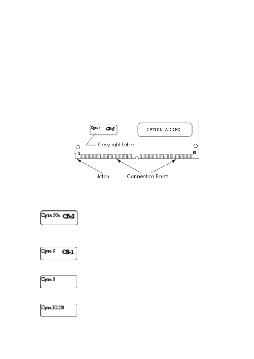
1. Unpack the SIMM for IPDS.
Avoid touching the connection points along the edge of the card. Your card may
vary in appearance. Save the packing materials.
2. Check the printer model and SIMM to be sure you install the SIMM in the correct
Optra model. The printer model number is located on the front or top cover.
Identify the SIMM by looking at the SIMM copyright label.
If the SIMM is labeled “Optra S/Se” and “CE-2” is
written on the copyright label, the SIMM may only be
used in the Optra S/Se models 1255, 1625, 1855, 2455
and 3455.
If the SIMM is labeled "Optra S" and "CE-1" is written
on the copyright label, the SIMM may only be used in
the Optra S models 1255, 1625, 1855 and 2455.
If the SIMM is labeled "Optra S" and the copyright
label is blank, the SIMM may only be used in the Optra
S models 1250, 1620, 1650, 2420 and 2450.
If the SIMM is labeled “Optra K 1220”, the SIMM may
only be used in the Optra K 1220.
Page 15
15
3. Turn the printer power Off (O) and unplug the printer power cord.
4. Disconnect all cables from the back of the printer.
5. You must access the printer system board. Refer to your printer User's Guide
and follow the instructions on how to access the printer system board. After
accessing the system board proceed to step 6.
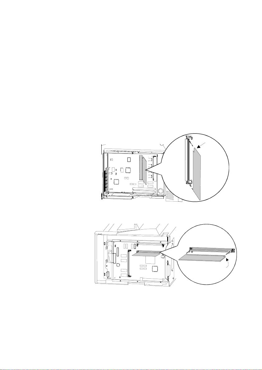
6. Locate the Optional Firmware SIMM Connector on the system board. Refer to the
figure below matching your printer. Hold the option with the connection points
pointing toward the system board and the notch as shown in the illustration for
your printer. Insert it all the way into the connector at a 45° angle.
Optra S/Se
Notch
Optra K
Notch
Page 16
16
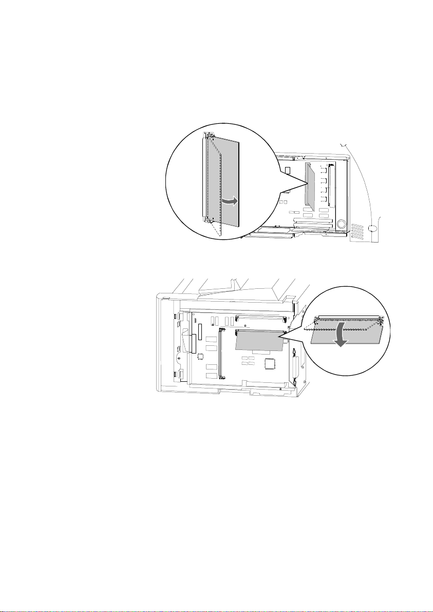
7. Press the option down toward the system board until it snaps into place. Make
sure both metal clips on the connector are fastened and the two pins on the
connector are pushed through the holes in the option. Refer to the figure matching
your printer.
Optra S/Se
Optra K
8. You must have at least 4 MB of installed memory to use the SIMM for IPDS.
Refer to the menu settings page you printed before beginning the SIMM
installation to determine the amount of printer installed memory. Refer to your
printer User’s Guide to install additional user memory and any other options.
After installing additional options, proceed to step 9.
9. Close the printer system board. Refer to your printer User's Guide and follow the
instructions on how to close the Printer System Board. After closing the Printer
System Board, proceed to step 10.
10. Reconnect the printer cables.
Page 17

17
11. Plug in the printer power cord.
12. Turn the printer power On (I).
Note: If all diamonds remain displayed on the printer operator panel or if
the printer does not warm the engine and display Ready on the
operator panel, follow the steps in the next section to remove the
SIMM and repeat the steps in this section to reinstall it. Be sure the
SIMM can be used in your printer model. Refer to step 2 for SIMM
identification.
A minimum of 4 MB of memory is required for IPDS printing. If
there is less than 4 MB of installed memory in the printer, the
message Not enough memory for IPDS is displayed in the operator
panel. This message is displayed at power on and when the IPDS
MENU is accessed. The IPDS Menu settings can be accessed and
configured but IPDS jobs can not be printed from the host. If there is
less than 4 MB of installed memory, a message will also be printed
on the IPDS Print Menus page. Jobs may be printed using other
emulations.
13. Reset the factory defaults.
a. Press Menu> until Test Menus appears. Press Select.
b. Press Menu> until Factory Defaults appears. Press Select.
c. Restore appears. Press Select. Resetting Factory Defaults is displayed
while the printer resets the defaults.
14. After you have finished installing the SIMM for IPDS, print a menu settings page
to verify the installation. The printed page lists current menu settings and installed
options.
a. Press Menu> until TESTS MENU appears. Press Select.
b. Press Menu> until Print Menus appears. Press Select.
c. Printing Menu Settings appears. The printer prints the menu settings pages,
which includes the IPDS MENU default settings.
Page 18

18
Note: After verifying the installation, you may want to set your other printer settings
that were different from the factory defaults. See the menu settings page you
printed before starting this installation for comparison.
Tip: Place a label on the front of the printer indicating the connector locations of all
installed options to avoid having to print the Menu Settings.
Page 19

19
2.4 Removing the SIMM for IPDS
Warning: The option card is easily damaged by static electricity. Before handling
the cards, be sure to touch the printer’s metal cabinet or put on an antistatic wrist strap.
1. Turn the printer power Off (O) and unplug the printer power cord.
2. Disconnect all cables from the back of the printer.
3. You must access the printer system board. Please refer to your printer's User's
Guide and follow the instructions on how to access the Printer System Board.
After accessing the Printer System Board, proceed to step 4.
Page 20
20
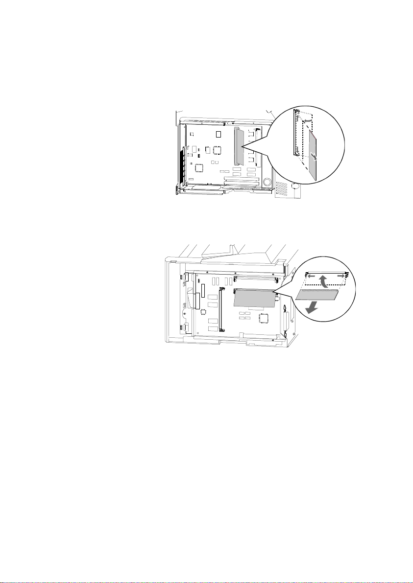
4. Refer to the figure below for your printer to locate the SIMM for IPDS in the
connector slot. Push out on the metal clips at each end of the connector and rotate
the SIMM away from the system board.
Optra S/Se
Optra K
5. Place the SIMM for IPDS in its original packaging. If you did not save the
packaging, wrap the card in paper and store it in a box.
6. Close the Printer System Board. Refer to your printer User's Guide and follow the
instructions on how to close the Printer System Board. After closing the Printer
System Board, proceed to step 7.
7. Reconnect the printer cables.
8. Plug in the printer power cord.
9. Turn the printer power On (I).
Page 21

21
3 Using the Setup Options
The SIMM for IPDS option settings are changed from the printer operator panel. This
section of the guide reviews how to change and save option settings.
See chapter 4 Setup Operations Reference for a listing of all possible values for each
option.
Note: Please refer to your printer's User's Guide for instructions on how to use
the Operator Panel. The layout of the operator panel may vary on the
different Optra models.
3.1 SIMM for IPDS Setup Options vs. Printer
Setup Options
Changes to the option settings under the IPDS Menu will only affect the way IPDS jobs
print. These changes will not affect PostScript or PCL jobs.
Changes to printer settings under the various printer menus will affect the way
PostScript and PCL jobs are printed. Many of these printer settings will affect IPDS
jobs, too.
This guide discusses changing the IPDS Menu settings. Please see your printer's User’s
Guide for information on changing other printer settings.
3.2 The IPDS Setup Menu
Access the SIMM for IPDS options and settings from the IPDS Menu. To reach the
menu:
1. From a Ready status, Press Menu> from the operator panel main screen until the
IPDS MENU appears in the second line of the display.
Note: Some printers have Menu+ and Menu-. On these printers, select
Menu+ for Menu> and Menu- for <Menu. Examples in this book will
use Menu> and <Menu.
Page 22

22
2. Press Select to select the IPDS MENU.
You can modify printer settings by:
• Selecting a setting from a list of values.
• Changing a numerical setting.
• Changing an On/Off setting.
Examples of changing each type of setting follow.
3.3 Selecting a New Value as a Setting
1. From a Ready status message, press Menu> or <Menu. The menu names appear.
2. Continue to press and release Menu> or <Menu until you reach the menu you
need.
3. Press Select to select the menu or menu item shown on the second line of the
display.
• If the selection is a menu, the menu is opened and the first printer
setting in the menu is displayed.
• If the selection is a menu item, the current setting for the menu item is
displayed. (The current user default setting has an asterisk (*) beside
it.)
Each menu item has a list of valid values for the menu item. A value can be:
• A phrase or word to describe a setting.
• A numerical value that can be changed.
• An On or Off setting.
4. Press Menu> or <Menu to move to the value you need.
Page 23
23
5. Press Select to select the value on the second line of the display. An asterisk
appears beside the value to indicate that it is now the user default setting. The
display shows the new setting for one second and then clears and shows the word
Saved. It then displays the previous list of menu items.
6. Press Return to go back to previous menus. Then, make additional menu
selections to set new default settings. Press Go once to return to the IPDS MENU
and a second time to return to Ready if this is the last printer setting to change.
User default settings remain in effect until you save new settings or restore the factory
defaults. See section 3.6 Activating Saved Option Changes on page 25.
Settings you choose from your IPDS print job may override the user default settings
you select from the printer operator panel.
3.4 Selecting a Setting from a List of Values
When you select some menu items, the printer displays a list of values. Press the
Menu> button to cycle through all the available items. To choose a new user default
setting, press Select.
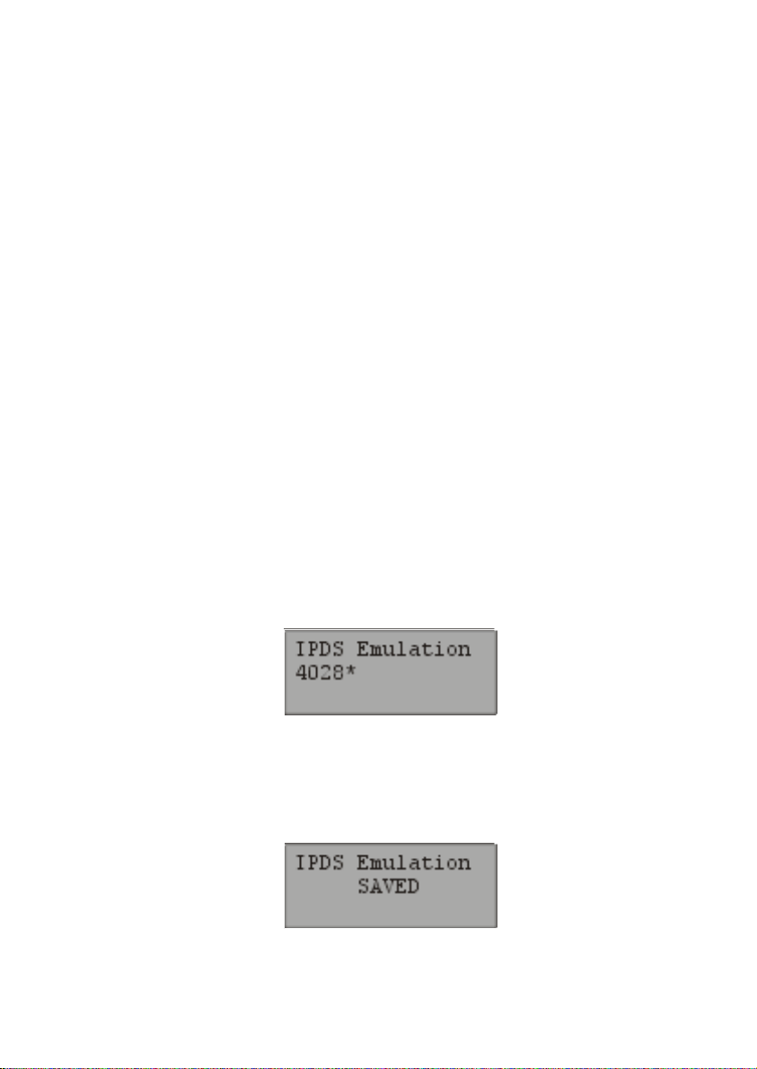
For example, if you select IPDS MENU, EMULATION, IPDS Emulation, you see
the following in the front panel display:
Cycle through the various emulations by pressing Menu> or <Menu. Press Select to
select the appropriate IPDS emulation. SAVED appears on the display for one second.
An asterisk (*) displays next to the value you selected to indicate it is the new user
default.
Page 24

24
If this is the last printer setting to change, press Return to back up to the list of menus.
Press Go twice to display the Ready status message. See section 3.6 Activating Saved
Option Changes on page 25.
3.5 Changing a Numerical Setting
If you choose a menu item that has a numerical value, the item name appears in the first
line of the operator panel display and the numerical value displays in the second line of
the operator panel display.
The current setting has an asterisk (*) next to it.
To increase the numerical value, press Menu>; to decrease the current setting, press
<Menu. The displayed setting changes accordingly. To save the new setting, press
Select. An asterisk (*) is displayed next to the new setting.
For example, if you select MENUS, IPDS MENU, PAPER HANDLING, Top
Margin, you see the following display:
Press Menu> or <Menu to increase or decrease the offset in pels for the default top
margin. Then press Select. The display shows the new settings for one second and then
clears and shows the word SAVED. Press Return to back up the list of menus, or press
Go once to display the IDPS MENU and a second time to display the Ready status
message if this is the last printer setting to be changed. See Activating Saved Option
Changes below.
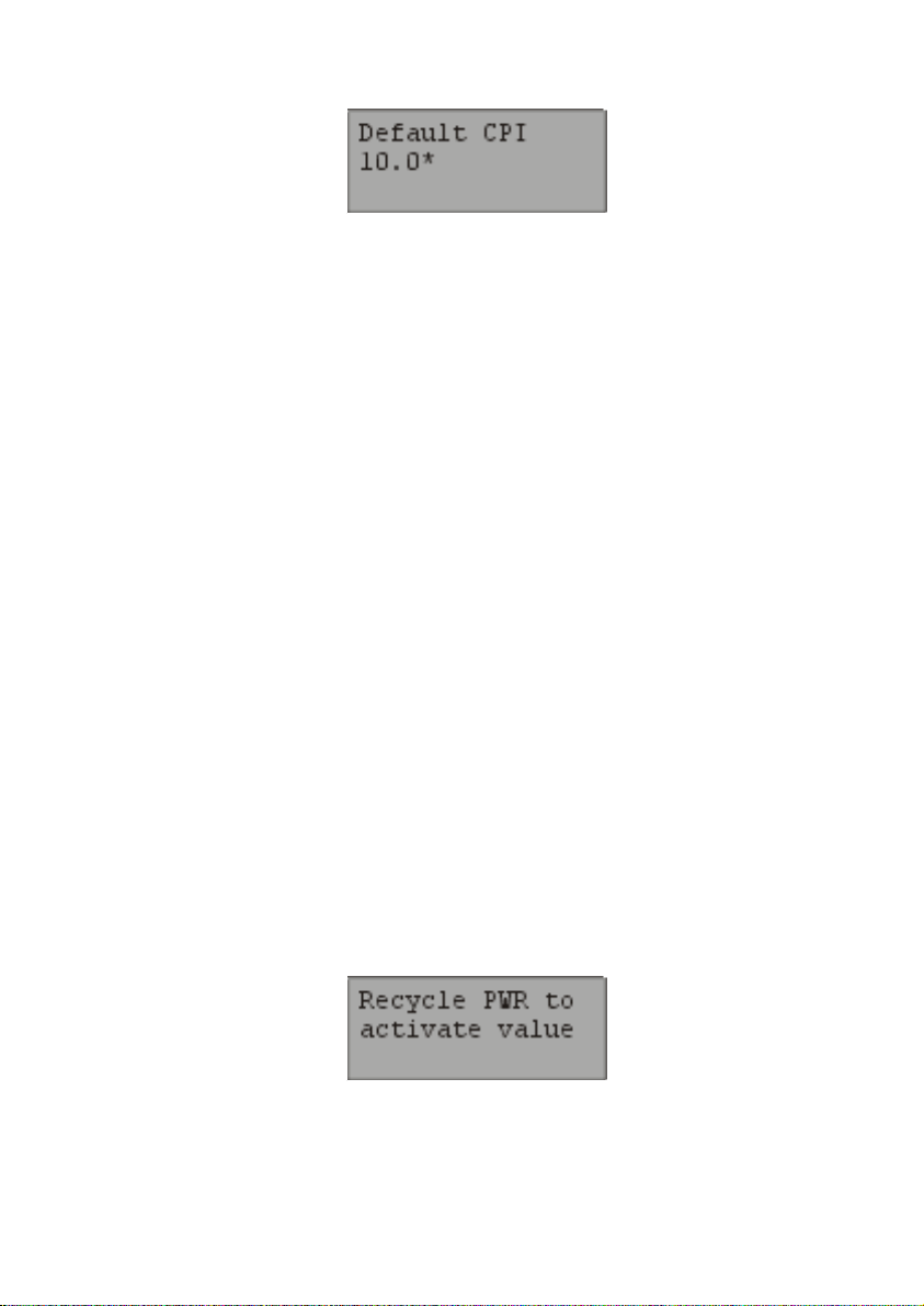
Another type of numerical value is found if you select MENUS, IPDS MENU,
EMULATION and Default CPI. This option consists of two numbers, which are set
independently of each other. Use Menu> or <Menu to increase or decrease the number
value. Press Select to switch to the second number after setting the first. Press Select
again to save the value. See display below.
Page 25
25
3.6 Activating Saved Option Changes
You may need to power the printer Off and On to activate an option change. See the
section below, which corresponds to your "attachment" method.
LAN Attachment
Most changes to IPDS MENU settings are active on the very next IPDS print job. This
is true when you are LAN attached using a MarkNet S, MarkNet Pro, or MarkNet XLe
adapter. When the IPDS Timeout option is set to a value other than Host Controlled,
you will have to power the printer Off and On to activate some menu setting changes.
See note below.
Coax/Twinax Attachment
If you are attached to your host using a coax or twinax connection, most settings do not
become active until the printer is powered Off and On. You should power the printer
Off and On, if you want the settings to be used for your next print job.
Note: If you are LAN attached with the IPDS Timeout option set to a value
other than Host Controlled or if you are using a coax or twinax
attachment, the warning message below is displayed if changes do not take
effect immediately.
Page 26

26
Page 27
27
4 Setup Operations Reference
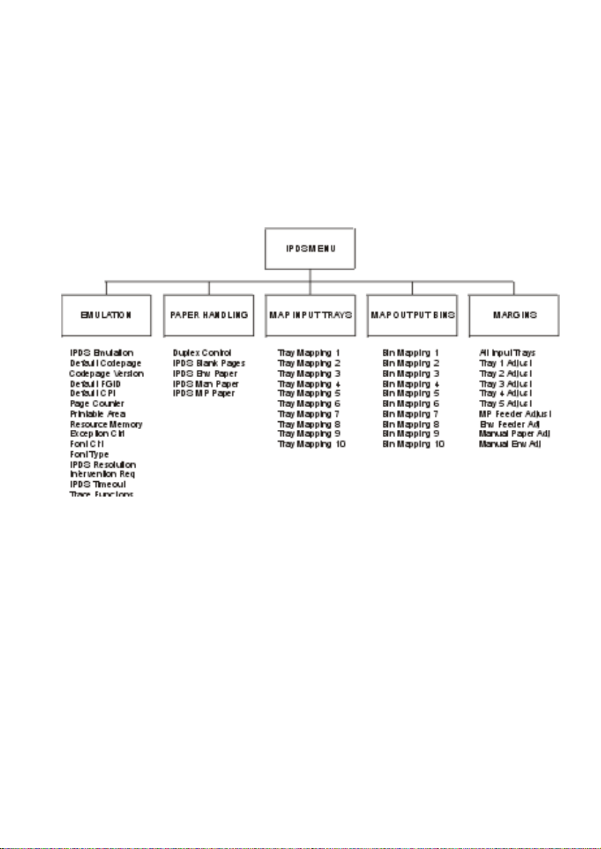
4.1 SIMM for IPDS Options Menu Map
This section describes the menu structure for the SIMM for IPDS. Settings are
displayed under the sub-menus reached from the IPDS MENU.
Note: Some menu items may not display on your printer. Refer to the specific
Menu Option or Option Value for details.
Some options are only activated after the printer power has been recycled.
Refer to section 3.6 Activating Saved Option Changes on page 25.
To reach any of the sub-menus, press Menu> until IPDS MENU appears on the
second line of the printer operator panel. Press Select to select the IPDS MENU.
Page 28

28
4.2 Overview of the EMULATION Menu Options
The following lists all menu options found under the EMULATION Menu. Values
only display when they are available on your printer.
An asterisk “*” indicates the default factory value. The selected value for each of these
options is listed on the IPDS Print Menus page. See section 2.2 Printing the Menu
Settings on page 13.
Option name Values
IPDS Emulation 4028*, 3112/3116, 43xx, 3812/3816
Default Codepage Codepages A - E
Arabic 420…Estonian 1122
Codepages F - K
Fin/Sweden 278...Int. Set 5 500*...Japan (Eng) 281
Codepages L - Z
Latin 2 870…USA/Canada 1140
Codepage Version Version 1*, Version 0
Default FGID 11*, refer to the option description on page 32
Default CPI 10.0*, range: 5.0 – 30.0
Page Counter Normal Update*, Early Update
Printable Area Whole Page*, Print Page, Physical Page, Full Page
Resource Memory Normal*, More, Less
Exception Ctrl Report All*, Sup Beyond VPA, Sup Undef Char,
Suppress Both
Font Ctrl Relaxed*, Strict
Font Type Use Scalable*, Use Bitmap
Page 29

29
IPDS Resolution 600 dpi*, 1200 dpi, 300 dpi
Intervention Req Report*, Do not report
IPDS Timeout Host Controlled*, 15 seconds, 30 seconds, 60
seconds, 90 seconds, 2 minutes, 3 minutes, 5
minutes, 10 minutes
Trace Functions Disable*, Serial Output, Parallel Output
A detailed description of each EMULATION Menu option follows.
Page 30

30
4.3 EMULATION Menu Options
In the following an asterisk “*” indicates the default factory value.
4.3.1 IPDS Emulation
This option selects the printer emulation to be used.
4028* IBM 4028 emulation
3112/3116 IBM 3112/3116 emulation
43xx IBM 4312, 4317 or 4324 emulation
3812/3816 IBM 3812/3816 emulation
Note: The 3812/16 emulation does not support the printer IPDS Resolution setting
of 300 dpi. If 3812/16 emulation is selected and the printer IPDS Resolution
setting is 300 dpi, the printer IPDS emulation ignores the 300 dpi setting and
uses 600 dpi. This means, that the 240 dpi data received from the host is
converted to the printer's working resolution of 600 dpi.
Page 31

31
4.3.2 Default Codepage
This option defines the default code page with the appropriate character set to be used.
Values are in alphabetical order. The panel will display code page options beginning
with the letters A - E, then F – K, and L - Z. Select the appropriate path to reach the
desired code page.
Codepages A – E Codepages F – K Codepages L – Z
Arabic 420 Fin/Sweden 278 Latin 2 870
ASCII 367 Fin/Sweden 1143 Latin 2 1110
Aus/Ger 273 Fin/Swe Alt 288 Latin 4 1069
Aus/Ger 1141 France 297 OCR-A 892
Aus/Ger Alt 286 France 1147 OCR-B 893
Baltic 1112 Greek 423 PC std 437
Belgium 274 Greek 875 Portugal 037
Brazil 275 Hebrew 424 Portugal 282
Can. French 260 Hebrew 803 Publishing 361
Can. French 276 Iceland 871 Spain/L. Am 284
Cyrillic 880 Iceland 1149 Spain/L. Am 1145
Cyrillic 1025 Int. Set 5 500* Spain Alt 289
Den/Nor 277 Int. Set 5 1148 Turkish 905
Den/Nor 1142 Italy 280 Turkish 1026
Den/Nor Alt 287 Italy 1144 UK 285
Estonian 1122 Japan (Eng) 281 UK 1146
USA/Canada 037
USA/Canada 1140
Note: Code pages 1140 – 1149 support the new euro symbol. They are only
available on IPDS code level 8223 and above.
IPDS code levels below 8223 have only two code page groups.
4.3.3 Codepage Version
This option determines which version of a code page is used. Some of the code pages
are available in two versions. Some characters differ between the two versions of the
same code page. If characters print differently than those entered on the keyboard,
check the code page version.
Version 1* Use version 1 of appropriate code pages.
Version 0 Use version 0 of appropriate code pages.
Page 32

32
4.3.4 Default FGID
Selects the default FGID to be used by the printer IPDS emulation when the host does
not send an FGID at the start of a job. This option is only available on IPDS emulation
code level 8141 or higher.
The option has three submenus containing the FGIDs used in each emulation. In the
table below the emulations are cross-referenced to pages in appendix B. Font and Code
Page Information. The FGIDs in the referenced tables are available in the operator
panel.
Option name Values
3812/3816 FGID See page 138, 143 and 146
4028/31xx FGID See page 138, 143 and 144
43xx FGID See page 138, 143 and 144
The 4028/31xx and 43xx printers all use 300 pel fonts. Selecting a Default FGID
value under the 4028/31xx menu or the 43xx menu will automatically change the
Default FGID value of the other 300 pel emulations. The 3812/16 FGID is not
affected by the other menu selections.
11* Default FGID for 3812/3816.
416* Default FGID for 4028/31xx and 43xx. When using a CPI value
of 10.0 FGID 416 is equal to FGID 11.
4.3.5 Default CPI
Selects the default characters per inch (CPI) to be used by the printer IPDS emulation
when the host does not send a CPI value at the start of a job. The option does not apply
to the fixed pitch fonts. This option is only available on IPDS emulation code level
8141 or higher.
The range is 5.0 to 30.0.
10.0* Default CPI
Page 33

33
4.3.6 Page Counter
This option selects the method used for updating IPDS page counters.
Normal Update* Jam and stacked page counters are updated when pages are
printed.
Early Update All page counters are updated when they are processed but not
printed. Pages may be lost if power or printer failure occurs.
However, selecting this option may increase printing speed.
Note: When Early Update is selected, Intervention Required
messages are not reported to the IPDS Host.
Page 34

34
4.3.7 Printable Area
This option defines the printable area on the page and how clipping is treated. Top,
bottom, and side margins for your print jobs are set through your print application.
4028 Whole Page* The printable area is 50 pels (4mm) inside the physical page. The
printable area is reported to the host. Clipping occurs if data is
printed outside the printable area. All four edges will clip.
4028 Print Page The printable area is 50 pels (4mm) inside the physical page. The
printable area is reported to the host. If the logical page is outside
the printable area it is moved down and to the right. The right and
bottom edges will be clipped.
Physical Page The printable area is the physical page (edge to edge). The
physical page printable area is reported to the host. With this
setting active, you may need to adjust the left margin setting.
Note: Only the Optra S/Se printer can physically print edge
to edge. No clipping will occur. Continual printing
within 50 pels of the paper edge is not recommended.
It can result in poor print quality and paper jams due
to toner contamination of the paper path. All other
printer models will report the physical page printable
area but will clip any text printed within 50 pels of any
edge.
Full Page The job is formatted for a page using a printable area, which is
edge to edge. However, when the page is actually printed, the
page image is compressed 2% in both the horizontal and vertical
directions.
Note: Full Page is only available on the Optra S/Se printer
models.
Page 35

35
4.3.8 Resource Memory
This option defines the amount of memory to be used as IPDS Resource Memory.
Increasing memory can sometimes improve performance because more fonts or other
resources are retained in memory reducing transmission and printing times. Increasing
memory for resources is recommended, if printing large IPDS jobs with many
downloaded fonts, page segments, or overlays.
The actual amount of available memory depends on how much memory is being used
by PostScript and PCL jobs.
Less Up to 1.125MB plus 12.5% of memory above 4MB can be used as
IPDS resource memory.
Normal* Up to 1.25MB plus 25% of memory above 4MB can be used as IPDS
resource memory.
More Up to 1.5MB plus 50% of memory above 4MB can be used as IPDS
resource memory.
Note: Resource Memory appears as an option in the printer panel only if you have
more than 4MB of installed memory.
Page 36

36
4.3.9 Exception Control
It is often practical to suppress exception reporting on undefined characters and on
position errors (printing outside the valid printable area (VPA)). This option overrides
the Exception Handling Control in the IPDS data stream.
Report All* No suppression of exceptions. Exception reporting is controlled
by the IPDS data stream.
Sup beyond VPA Exception reporting or position errors (outside VPA) is
suppressed. The printer IPDS emulation will print the IPDS job
but not report "08C1" printable area exceptions or "0411" bar
code exceptions to the host.
Sup Undef Char If an undefined character is found, Exception Reporting is
suppressed. The printer IPDS emulation will print the IPDS job
but not report "0821" undefined character exceptions to the host.
Suppress Both Both position errors and undefined character exceptions are
suppressed.
Page 37

37
4.3.10 Font Control
This option defines how strict the reporting will be if a selected font does not
correspond to a valid combination of code page and character set.
Relaxed* The printer makes an intelligent decision concerning whether the
selected combination of code page and character set is adequately
supported. A Relaxed setting will report very few exceptions. If the
selected font is not found, the printer will substitute with the closest
matching font. If a font/code page combination is selected, which is not
fully supported, characters may be missing.
Strict A strict setting reports exceptions when a requested font/code page or
substituted font/code page combination is not valid. The strict setting
prints all characters.
4.3.11 Font Type
This option selects the type of fonts used by the printer when a fixed pitch Courier,
Prestige, or Letter Gothic Font is requested by the host.
Use Scalable* Use printer resident scalable fonts for Courier, Prestige, and Letter
Gothic fonts when bitmap font Font IDs are received from the host.
Use Bitmap Use printer resident bitmap fonts for Courier, Prestige, and Letter
Gothic fonts when bitmap font IDs are received from the host.
Page 38

38
4.3.12 IPDS Resolution
This option defines the resolution used when printing IPDS jobs. This is a separate
setting from the printer's Print Resolution under the Quality Menu.
This option sets the working print resolution for the IPDS jobs. This alters the quality
of text with scalable fonts, barcodes, graphics, and scalable images. Bitmap fonts and
non-scalable images are not affected.
600 dpi* Print at 600 pel resolution
1200 dpi Print at 1200 pel resolution
300 dpi Print at 300 pel resolution
Note: The 3812/16 emulation does not support the printer IPDS Resolution
setting of 300 dpi. If 3812/16 emulation is selected and the printer IPDS
Resolution setting is 300 dpi, the printer IPDS emulation ignores the 300
dpi setting and uses 600 dpi. This means, that the 240 dpi data received
from the host is converted to the printer's working resolution of 600 dpi.
Some jobs may not print in the standard 4MB of installed printer memory. The 300 dpi
resolution uses the least amount of memory. Switch to this resolution if your job will
not print in the memory installed in the printer or add additional memory. Refer to
appendix C. Recommended memory on page 151 for minimum total recommended
memory for each resolution setting. Additional memory above the total recommended
may be required for printing complex pages. Additional memory may also increase
print speed.
Page 39

39
4.3.13 Intervention Required
This option defines if the emulation should report Intervention Required messages to
the host. Types of intervention required messages include a paper jam, paper out, cover
open or offline message. These types of messages mean the printer is not ready to print.
Report* Report intervention required messages to the host. This is the
typical setting.
Do Not Report Do not report intervention required messages to the host. Used
only in special cases.
Note: When Page Counter is set to “Early Update”,
Intervention Required messages are not reported to the
host.
Page 40

40
4.3.14 IPDS Timeout
This option either allows the host to directly control when an IPDS LAN session with a
printer ends (disconnects) or allows the printer IPDS emulation to determine when an
IPDS LAN session times out.
Note: The IPDS Timeout values are only used by the printer IPDS emulation
when the printer is LAN attached using a MarkNet S adapter.
Note: This option is only available on IPDS emulation code level 8141 or higher.
The printer is capable of receiving jobs on multiple printer ports. While the printer is
busy printing jobs from one printer port, jobs on other printer ports remain in a waiting
status. When the host disconnects from the printer or when the printer IPDS emulation
times out, the printer automatically switches to another printer port to start a new job.
Host Controlled should be selected as the IPDS Timeout value when the host port
value is 9100 or 9102. The printer defaults to Host Controlled when receiving IPDS
jobs on port 9100 or 9102. Host Controlled or the timeout values (15 seconds to 10
minutes) may be used when the host port value is 9600. The host port value is
specified when configuring the printer parameters on the host.
Host Controlled*
The printer IPDS emulation remains active until the host
disconnects from the printer. Host timer/timeout values control
when the host will disconnect. When the host disconnects, the
printer will print jobs from other printer ports.
Host Timer/Timeout Values and Actions: The host
timer/timeout value should be set to a small value (15 to 30
seconds) so the host will quickly disconnect after an IPDS job
is printed. All IPDS resources downloaded to the printer will
be deleted when the host disconnects. A disabled or large host
timer/timeout value will cause the printer IPDS emulation to
remain active. The printer busy light will flash and IPDS will
remain on the printer operator panel even though the printer
has completed processing and printing the IPDS job.
Page 41

41
15 seconds
30 seconds
60 seconds
90 seconds
2 minutes
3 minutes
5 minutes
10 minutes
Note: • Up to four different LAN sessions may be active on port 9600.
IPDS emulation timeout value. These values are only used by
the printer IPDS emulation when the host sends IPDS jobs on
port 9600 to a MarkNet S adapter. If the host does not send
another IPDS job or send additional IPDS resource data to the
printer within the timeout value specified, the printer IPDS
emulation will time out, place all IPDS resources in temporary
storage (see Storage of IPDS Resources below), and allow the
printer to print jobs from other printer ports.
Host Timer/Timeout Values and Actions: While the printer is
printing jobs from other printer ports, the host is still connected
to the printer. The host timer/timeout value should be disabled
or set to a large value to prevent the host from disconnecting
and deleting the resources downloaded to the printer.
Requests for additional sessions will be ignored until the host
disconnects from one of the established sessions.
• The IPDS Timeout values are not active when the printer is
connected to a host through an SCS adapter card. The IPDS
timeout is controlled by the Coax or Twinax timeout value on
the SCS adapter card.
• The IPDS Timeout value defaults to Host Controlled when the
printer is connected to a host through a MarkNet Pro or
MarkNet XLe print server. The host port value must be 9100 or
9102 to communicate with these print servers.
See Storage of IPDS Resources on next page for additional information.
Page 42

42
Storage of IPDS Resources
Up to four different LAN sessions may be connected to port 9600. IPDS resources
from the last active port 9600 session are temporarily stored in the printer memory
when IPDS Timeout values (15 seconds to 10 Minutes) are selected and the host
timer/timeout values are set to a large value or disabled. Operator actions and
processing of other jobs may cause the resources to be deleted. Events such as the
following will cause deletion of the downloaded resources.
• The host ends the IPDS port 9600 session.
• TCP/IP communications is interrupted on the port 9600 session.
• Another IPDS session is started on port 9100, 9102, or 9600.
• IPDS Menu option values are changed.
• Processing of a non-IPDS job which requires more memory than is available in
printer memory.
• Reset Printer is selected on the operator panel.
• The printer is powered OFF.
If the IPDS resources are deleted, the printer will return a Printer Reset exception to the
host. The host will download the resources again with the next IPDS job.
Page 43

43
4.3.15 Trace Functions
This option determines if the Trace function is enabled. Trace data is sent to either the
serial or parallel port. Unless you have a computer running a capture program attached
to the serial or parallel port to receive the trace data, the printer will hang Busy and
display IPDS on the first line of the operator panel and TRC on the second line of the
operator panel.
Note: The Trace function is used by service personnel for troubleshooting and
service.
Disable* Disable Trace
Serial Output Enable serial port for output of trace data
Parallel Output Enable parallel port for output of trace data
Note: Some Optra models do not have a serial port standard on the printer. A Tri-
Port Adapter must be installed in printer option card slot one to perform
serial tracing on these models.
Page 44

44
4.4 Overview of the PAPER HANDLING Menu
Options
The following lists all menu options found under the PAPER HANDLING Menu.
Values only display when they are available on your printer. An asterisk “*” indicates
the default factory value. The selected value for each of these options is listed on the
IPDS Print Menus page. See section 2.2 Printing the Menu Settings on page 13.
Option name Values
Duplex Control Autodetect*, Enabled, Disabled
IPDS Blank Pages Print*, Do Not Print
IPDS Env Paper Prtr Setting*, Letter, Legal, B5(JIS),
A4, Executive, A5,
7 ¾ Envelope, 9 Envelope,
10 Envelope, DL Envelope,
C5 Envelope and B5 Envelope
IPDS Man Paper Prtr Setting*, Letter, ...
IPDS MP Paper Prtr Setting*, Letter, ...
A detailed description of each PAPER HANDLING option follows.
Page 45

45
4.5 PAPER HANDLING Menu Options
In the following an asterisk “*” indicates the default factory value.
4.5.1 Duplex Control
This option defines the treatment of duplex printing.
Autodetect* Use and report duplex if duplexer is installed.
Enable Always report duplex.
If a duplexer is not installed, the pages are printed in simplex.
Disabled Do not report duplex.
Pages are printed in simplex even with a duplexer installed.
4.5.2 IPDS Blank Pages
This option determines if blank pages in IPDS print jobs are printed.
Print* Print all IPDS pages.
Do Not Print Skip printing of blank IPDS pages. Duplex pages are skipped only
if both sides are blank.
Page 46

46
4.5.3 IPDS Envelope Paper
This option selects the envelope default formatting size for the IPDS Envelope media
source (most often it is the IPDS Number 64 (40H)). This option setting applies to
Input Tray Mappings set to "Manual Env" or "Env Feeder".
You can do one of the following:
• Use the printer setting Manual Env Size.
• Use the printer setting Env Feeder Size (if installed).
• Select a different envelope size for IPDS. The selection applies to both
Manual Env and Env Feeder.
Prtr (printer) Setting* Use the envelope size from the Manual Env Size or Env
Feeder Size printer default setting.
7 ¾ Envelope 7 ¾ Monarch envelope paper (3.875” x 7.5”)
9 Envelope 9 Commercial envelope paper (3.875” x 8.875”)
10 Envelope 10 Commercial envelope paper (4.125” x 9.5”)
DL Envelope DL envelope paper (110mm x 220mm)
C5 Envelope C5 envelope paper (162mm x 229mm)
B5 Envelope B5 envelope paper (176mm x 250mm)
Page 47

47
4.5.4 IPDS Manual Paper
This option selects the default formatting paper size for the IPDS Manual media source
(most often it is the IPDS Number 99 (63H)). This option setting applies to the Input
Tray Mappings set to "Manual Paper".
You can do one of the following:
• Use the printer setting “Manual Pap Size”.
• Select a different paper size for IPDS.
Prtr (printer) Setting* Use the paper size from the “Manual Pap Size” printer
default setting.
Letter Letter paper size (8.5” x 11.0”)
Legal Legal paper size (8.5” x 14.0”)
B5 (JIS) B5 (JIS) paper size (182mm x 257mm)
A4 A4 paper size (210mm x 297mm)
Executive Executive paper size (7.25” x 10.5”)
A5 A5 paper size (148mm x 210mm)
Page 48

48
4.5.5 IPDS Multipurpose (MP) Paper
This option selects the default formatting paper size or envelope default formatting size
for the IPDS multipurpose (MP) media source. This option setting applies to the Input
Tray Mappings set to "MP Feeder".
Note: This option only displays if a Multipurpose Feeder is installed.
You can do one of the following:
• Use the printer setting “MP Feeder Size”.
• Select a different paper size or envelope size for IPDS.
Prtr (printer) Setting* Use the paper size or envelope size from the MP Feeder
Size printer default setting.
PAPER:
Letter Letter paper size (8.5” x 11.0”)
Legal Legal paper size (8.5” x 14.0”)
B5 (JIS) B5 (JIS) paper size (182mm x 257mm)
A4 A4 paper size (210mm x 297mm)
Executive Executive paper size (7.25” x 10.5”)
A5 A5 paper size (148mm x 210mm)
ENVELOPES:
7 ¾ Envelope 7 ¾ Monarch envelope paper (3.875” x 7.5”)
9 Envelope 9 Commercial envelope paper (3.875” x 8.875”)
10 Envelope 10 Commercial envelope paper (4.125” x 9.5”)
DL Envelope DL envelope paper (110mm x 220mm)
C5 Envelope C5 envelope paper (162mm x 229mm)
B5 Envelope B5 envelope paper (176mm x 250mm)
Page 49

49
4.6 MAP INPUT TRAYS Menu Options
This option defines the mapping of the host's request for a physical feeder or input tray
in the printer. Any host input source can be mapped to any printer input source. The
printer input source is mapped to an IPDS host number. Input sources include the
envelope feeder, manual feed paper or manual feed envelopes.
The labels Tray Mapping 1 - Tray Mapping 10 refer to the number of the mapping, not
the physical tray.
Note: The optional printer input sources will only be displayed when installed on
the printer.
A typical relationship between IPDS numbers and the input sources would be:
IPDS Number Printer Input Source
0 Tray 1
1 Tray 2
2 Tray 3
3 Tray 4
4 Tray 5
64 (40H) Envelopes (Manual or Feeder)
99 (63H) Manual Paper
Example 1
You may want to use one of the higher capacity input trays for IPDS 000. To swap the
IPDS number for Tray 1 and Tray 2, you will need to do the following:
1. Set TRAY MAP 2 for Tray 2 to "IPDS 000".
2. Set TRAY MAP 1 for Tray 1 to "IPDS 001".
This will give you:
TRAY MAP 1 = IPDS 001 mapped to Tray 1
TRAY MAP 2 = IPDS 000 mapped to Tray 2
Page 50

50
Example 2
If an IPDS number is mapped (used) twice, the lowest tray mapping number is
activated (if available). For example if Tray Mapping 6 and 7 both map to IPDS 64 as
shown below, the printer will select media from the Env Feeder.
Tray Mapping 6 IPDS 64 Env Feeder
Tray Mapping 7 IPDS 64 Manual Env
In other words, the printer attempts to map to (select media from) the Env Feeder first
and if it is not installed, the printer defaults to Manual Env.
Example 3
To link multiple input trays as one big input tray, you need to make changes under the
printer's PAPER MENU. You need to set the PAPER SIZE and PAPER TYPE for
each of the trays you want to link to the same value.
For example, the host expects colored paper in Tray 1 and you want to link Tray 2 and
Tray 3, which have plain paper. Do the following:
Leave the MAP INPUT TRAYS at their defaults:
TRAY MAP 1 = IPDS 000 mapped to Tray 1
TRAY MAP 2 = IPDS 001 mapped to Tray 2
Insert letter-size colored paper in Tray 1. Insert letter-size plain paper in Trays 2 and 3.
The paper size is detected by the printer:
Tray 1 Size = Letter
Tray 2 Size = Letter
Tray 3 Size = Letter
Page 51

51
Set the PAPER TYPE for the three trays as follows:
Tray 1 Type = Colored Paper
Tray 2 Type = Plain Paper
Tray 3 Type = Plain Paper
The printer will feed paper from Tray 3 when Tray 2 is empty.
4.6.1 Tray Mapping
In the following an asterisk “*” indicates the default factory value. The default value
for each of these options is listed on the IPDS Print Menus page. See section 2.2
Printing the Menu Settings on page 13.
Note: Values which are not available on your printer will not be displayed.
Option name Values
Tray Mapping 1 No Map, Tray 1*, Tray 2, Tray 3, Tray 4, Tray 5, MP Feeder,
Env Feeder, Manual Paper, Manual Env
IPDS Number 0*, 0 to 255
Tray Mapping 2 No Map, Tray 1, Tray 2*, Tray 3, Tray 4, Tray 5, MP Feeder,
Env Feeder, Manual Paper, Manual Env
IPDS Number 1*, 0 to 255
Tray Mapping 3 No Map, Tray 1, Tray 2, Tray 3*, Tray 4, Tray 5, MP Feeder,
Env Feeder, Manual Paper, Manual Env
IPDS Number 2*, 0 to 255
Tray Mapping 4 No Map, Tray 1, Tray 2, Tray 3, Tray 4*, Tray 5, MP Feeder,
Env Feeder, Manual Paper, Manual Env
IPDS Number 3*, 0 to 255
Page 52

52
Tray Mapping 5 No Map, Tray 1, Tray 2, Tray 3, Tray 4, Tray 5*, MP Feeder,
Env Feeder, Manual Paper, Manual Env
IPDS Number 4*, 0 to 255
Tray Mapping 6 No Map, Tray 1, Tray 2, Tray 3, Tray 4, Tray 5, MP Feeder,
Env Feeder*, Manual Paper, Manual Env
IPDS Number 64*, 0 to 255
Tray Mapping 7 No Map, Tray 1, Tray 2, Tray 3, Tray 4, Tray 5, MP Feeder,
Env Feeder, Manual Paper, Manual Env*
IPDS Number 64*, 0 to 255
Tray Mapping 8 No Map, Tray 1, Tray 2, Tray 3, Tray 4, Tray 5, MP Feeder,
Env Feeder, Manual Paper*, Manual Env
IPDS Number 99*, 0 to 255
Tray Mapping 9 No Map*, Tray 1, Tray 2, Tray 3, Tray 4, Tray 5, MP Feeder,
Env Feeder, Manual Paper, Manual Env
IPDS Number X, 0 to 255
Tray Mapping 10 No Map*, Tray 1, Tray 2, Tray 3, Tray 4, Tray 5, MP Feeder,
Env Feeder, Manual Paper, Manual Env
IPDS Number X, 0 to 255
Page 53

53
4.7 MAP OUTPUT BINS Menu Options
This option defines the mapping of the host's request for a physical output bin in the
printer. The printer bin is mapped to an IPDS host number. Printer output bins include
the top of the printer (standard bin) and optional output bins that attach to the top of the
printer.
The labels Bin Mapping 1- Bin Mapping 10 refer to the number of the mapping, not the
physical output bin.
If an IPDS number is mapped (used) twice, the lowest bin mapping (if available) is
used.
A typical relationship between IPDS numbers and the output bins would be:
IPDS Number Printer Output Bin
1 Standard Bin
2 Bin 1
3 Bin 2
4 Bin 3
Page 54

54
4.7.1 Bin Mapping
Note: Output Bin values will only be displayed when optional output bins are
installed.
In the following an asterisk “*” indicates the default factory value. The default value
for each of these options is listed on the second Print Menus page. See section 2.3
Installing the SIMM for IPDS on page 17, step 14.
Option name Values
Bin Mapping 1 Standard Bin*, No Map, Output Bin 1, Output Bin 2, Output
Bin 3
IPDS Number 1*, 1 to 255
Bin Mapping 2 Standard Bin, No Map, Output Bin 1*, Output Bin 2, Output
Bin 3
IPDS Number 2*, 1 to 255
Bin Mapping 3 Standard Bin, No Map, Output Bin 1, Output Bin 2*, Output
Bin 3
IPDS Number 3*, 1 to 255
Bin Mapping 4 Standard Bin, No Map, Output Bin 1, Output Bin 2, Output Bin
3*
IPDS Number 4*, 1 to 255
Bin Mapping 5 Standard Bin, No Map*, Output Bin 1, Output Bin 2, Output
Bin 3
IPDS Number X, 1 to 255
Page 55

55
Bin Mapping 6 Standard Bin, No Map*, Output Bin 1, Output Bin 2, Output
Bin 3
IPDS Number X, 1 to 255
Bin Mapping 7 Standard Bin, No Map*, Output Bin 1, Output Bin 2, Output
Bin 3
IPDS Number X, 1 to 255
Bin Mapping 8 Standard Bin, No Map*, Output Bin 1, Output Bin 2, Output
Bin 3
IPDS Number X, 1 to 255
Bin Mapping 9 Standard Bin, No Map*, Output Bin 1, Output Bin 2, Output
Bin 3
IPDS Number X, 1 to 255
Bin Mapping 10 Standard Bin, No Map*, Output Bin 1, Output Bin 2, Output
Bin 3
IPDS Number X, 1 to 255
Page 56

56
4.8 MARGINS Menu Options
Use margin settings to adjust the position of the page image. Margin settings, which
could be compared to movements of the tractor feeder and paper knob of a matrix
printer, affect all IPDS jobs and are not affected by IPDS commands in the job.
The input tray Left Margin and input tray Top Margin option settings should not be
confused with the IPDS left and top margin settings sent from the host. Input tray Left
Margin settings adjust the page image left or right in relation to the paper leading
reference edge as it is fed through the printer. Input tray Top Margin settings adjust
the page image up or down in relation to the paper leading reference edge as it is fed
through the printer.
The input feeder Left Margin and input tray Top Margin option settings should not
be confused with the IPDS left and top margin settings sent from the host. Input feeder
Left Margin settings adjust the page image left or right in relation to the envelope
reference edge as it is fed through the printer. Input feeder Top Margin settings adjust
the page image up or down in relation to the envelope reference edge as it is fed
through the printer.
Page 57

57
Margins may be adjusted for all input trays and feeders using the All Input Trays
menu. Additional adjustments may be made to the All Input Trays margin settings for
an individual tray or feeder using the tray or feeder specific margin menu. Most often,
the All Input Trays margin settings will remain at the default setting of zero and
adjustments will be made using the specific tray or feeder margin menu. The All Input
Trays margin adjustment PLUS the specific tray or feeder margin adjustment
determines the total margin adjustment for a specific tray or feeder.
Margin Adjustment = All Input Trays setting + Specific Tray / Feeder Setting
The SIMM for IPDS is limited by the printer’s printable area. The Margins menu may
be used to adjust page images outside the valid printable area. The page image will be
clipped. Valid Printable Area (VPA) exception conditions will not be reported to the
host.
Margin adjustments are in 1/300ths of an inch.
Note: The Margins menu is only available on IPDS code level 8223 and above.
Example 1 – Margins
The All Input Tray Left Margin is set to the default of 0. The Tray 1 Adjust Left
Margin is set to +25. This adjusts the page image left margin for all pages printed from
tray 1 by 25/300ths of an inch to the right of the margin specified in the IPDS job.
Example 2 – Margins
The All Input Tray Left Margin has been adjusted to –25. This moves the left margin
for pages printed for all IPDS jobs 25/300ths of an inch to the left. The Tray 1 Adjust
Left Margin has been adjusted to +25. For tray 1, the additional Tray 1 Adjust Left
Margin value will also be used to adjust the left margin. The tray 1 left margin
adjustment will be zero for pages printed from tray 1. The All Input Trays Left
Margin adjustment PLUS the Tray 1 Adjust Left Margin adjustment equals the total
left margin adjustment. {–25 pels +25 pels = 0 adjustment}
Page 58

58
Margin and Tray Linking Interaction
When trays are linked, the margins set in the All Input Trays menu and the margins
set for the tray specified in the IPDS data stream will be used to adjust the page image
on the paper
Example 1 – Margin and Tray Linking
Tray 1 is requested as the input source from the host. If tray 1 and tray 2 are linked and
tray 1 runs out of paper, paper will be pulled from tray 2. The margin adjustments
applied when printing from tray 2 will be the All Input Trays margins PLUS the Tray
1 Adjust margins set for the requested IPDS input source (tray 1).
Example 2 – Margin and Tray Linking
Tray 2 is requested as the input source from the host. If tray 1 and tray 2 are linked and
tray 2 runs out of paper, paper will be pulled from tray 1. The margin adjustments
applied when printing from tray 1 will be the All Input Trays margins PLUS the Tray
2 Adjust margins set for the requested IPDS input source (tray 2).
Example 3 – Margin and Tray Linking
Tray 2 is requested as the input source from the host. If tray 2, tray 3, and tray 4 are
linked and tray 2 runs out of paper, paper will be pulled from tray 3 until it is empty
and then from tray 4. The margin adjustments applied when printing from tray 3 or tray
4 will be the All Input Trays margins PLUS the Tray 2 Adjust margins set for the
requested IPDS input source (tray 2).
Margin and Tray Mapping Interaction
When the host’s IPDS Number has been mapped to another input source using the
Tray Mapping option, the value of the Tray Mapping option will determine the
margin adjustment applied to pages printed from the selected tray.
Example – Margin and Tray Mapping
The host input source IPDS Number 1 normally selects the printer physical tray 2. If
IPDS Number 1 has been mapped to Tray 1, the Tray 1 Adjust margin values will be
applied to all pages in a job which have tray 2 specified as the input source.
Page 59

59
Each margin menu option has four sub-menus. The exception being the envelope menu
options, which have only two. The available margin menu options and their sub-menus
are shown below.
Margin menu option Top
Margin
All Input Trays x x x x
Tray 1 Adjust x x x x
Tray 2 Adjust x x x x
Tray 3 Adjust x x x x
Tray 4 Adjust x x x x
Tray 5 Adjust x x x x
MP Feeder Adjust x x x x
Env Feeder Adj x x
Manual Paper Adj x x x x
Manual Env Adj x x
Left
Margin
Top Margin
Back
Left Margin
Back
The following sections describe each of the margin menu options.
4.8.1 All Input Trays Menu
This menu option allows the top and left margins for simplex and duplex pages to be
adjusted. Margin settings of this menu option apply to pages printed from any tray or
feeder. Adjustments to the All Input Tray margin settings can be made by adjusting
the individual margin settings for a specific tray or feeder. Negative values indicate a
decrease in the margin value from the default margin of zero.
Intermediate Menu Value Function Performed
Left Margin 0*, -127 to 127 Adjusts the page front side left margin for pages
Top Margin 0*, -127 to 127 Adjusts the page front side top margin for pages
Left Margin Back 0*, -127 to 127 Adjusts the duplex page back side left margin for
Top Margin Back 0*, -127 to 127 Adjusts the duplex page back side top margin for
printed from all input trays and feeders.
printed from all input trays and feeders.
pages printed from all input trays and feeders.
pages printed from all input trays and feeders.
Page 60

60
4.8.2 Tray 1 Adjust Menu
This menu option allows additional adjustment to the top and left margins for simplex
and duplex pages printed from tray 1. Tray 1 Adjust margin settings adjusts the value
of the All Input Trays corresponding margin setting for all pages printed from tray 1.
See margin settings examples under 4.8 MARGINS Menu Options on page 56 for
additional information.
Intermediate Menu Value Function Performed
Left Margin 0*, -127 to 127 Adjusts the page front side left margin for pages
Top Margin 0*, -127 to 127 Adjusts the page front side top margin for pages
Left Margin Back 0*, -127 to 127 Adjusts the duplex page back side left margin for
Top Margin Back 0*, -127 to 127 Adjusts the duplex page back side top margin for
printed from tray 1.
printed from tray 1.
pages printed from tray 1.
pages printed from tray 1.
4.8.3 Tray 2 Adjust Menu
This menu option allows additional adjustment to the top and left margins for simplex
and duplex pages printed from tray 2. Tray 2 Adjust margin settings adjusts the value
of the All Input Trays corresponding margin setting for all pages printed from tray 2.
See margin settings examples under 4.8 MARGINS Menu Options on page 56 for
additional information.
Intermediate Menu Value Function Performed
Left Margin 0*, -127 to 127 Adjusts the page front side left margin for pages
printed from tray 2.
Top Margin 0*, -127 to 127 Adjusts the page front side top margin for pages
printed from tray 2.
Left Margin Back 0*, -127 to 127 Adjusts the duplex page back side left margin for
pages printed from tray 2.
Top Margin Back 0*, -127 to 127 Adjusts the duplex page back side top margin for
pages printed from tray 2.
Page 61

61
4.8.4 Tray 3 Adjust Menu
This menu option allows additional adjustment to the top and left margins for simplex
and duplex pages printed from tray 3. Tray 3 Adjust margin settings adjusts the value
of the All Input Trays corresponding margin setting for all pages printed from tray 3.
See margin settings examples under 4.8 MARGINS Menu Options on page 56 for
additional information.
Intermediate Menu Value Function Performed
Left Margin 0*, -127 to 127 Adjusts the page front side left margin for pages
Top Margin 0*, -127 to 127 Adjusts the page front side top margin for pages
Left Margin Back 0*, -127 to 127 Adjusts the duplex page back side left margin for
Top Margin Back 0*, -127 to 127 Adjusts the duplex page back side top margin for
printed from tray 3.
printed from tray 3.
pages printed from tray 3.
pages printed from tray 3.
4.8.5 Tray 4 Adjust Menu
This menu option allows additional adjustment to the top and left margins for simplex
and duplex pages printed from tray 4. Tray 4 Adjust margin settings adjusts the value
of the All Input Trays corresponding margin setting for all pages printed from tray 4.
See margin settings examples under 4.8 MARGINS Menu Options on page 56 for
additional information.
Intermediate Menu Value Function Performed
Left Margin 0*, -127 to 127 Adjusts the page front side left margin for pages
printed from tray 4.
Top Margin 0*, -127 to 127 Adjusts the page front side top margin for pages
printed from tray 4.
Left Margin Back 0*, -127 to 127 Adjusts the duplex page back side left margin for
pages printed from tray 4.
Top Margin Back 0*, -127 to 127 Adjusts the duplex page back side top margin for
pages printed from tray 4.
Page 62

62
4.8.6 Tray 5 Adjust Menu
This menu option allows additional adjustment to the top and left margins for simplex
and duplex pages printed from tray 5. Tray 5 Adjust margin settings adjusts the value
of the All Input Trays corresponding margin setting for all pages printed from tray 5.
See margin settings examples under 4.8 MARGINS Menu Options on page 56 for
additional information.
Intermediate Menu Value Function Performed
Left Margin 0*, -127 to 127 Adjusts the page front side left margin for pages
Top Margin 0*, -127 to 127 Adjusts the page front side top margin for pages
Left Margin Back 0*, -127 to 127 Adjusts the duplex page back side left margin for
Top Margin Back 0*, -127 to 127 Adjusts the duplex page back side top margin for
printed from tray 5.
printed from tray 5.
pages printed from tray 5.
pages printed from tray 5.
4.8.7 MP Feeder Adjust Menu
This menu option allows additional adjustment to the top and left margins for simplex
and duplex pages printed from the multipurpose feeder. MP Feeder Adjust margin
settings adjusts the value of the All Input Trays corresponding margin setting for all
pages printed from the MP feeder.
See margin settings examples under 4.8 MARGINS Menu Options on page 56 for
additional information.
Intermediate Menu Value Function Performed
Left Margin 0*, -127 to 127 Adjusts the page front side left margin for pages
printed from the MP feeder.
Top Margin 0*, -127 to 127 Adjusts the page front side top margin for pages
printed from the MP feeder.
Left Margin Back 0*, -127 to 127 Adjusts the duplex page back side left margin for
pages printed from the MP feeder.
Top Margin Back 0*, -127 to 127 Adjusts the duplex page back side top margin for
pages printed from the MP feeder.
Page 63

63
4.8.8 Env Feeder Adj Menu
This menu option allows additional adjustment to the top and left margins for jobs
printed from the envelope feeder. Env Feeder Adj margin settings adjusts the value of
the All Input Trays corresponding margin setting for all pages printed from the
envelope feeder.
See margin settings examples under 4.8 MARGINS Menu Options on page 56 for
additional information.
Intermediate Menu Value Function Performed
Left Margin 0*, -127 to 127 Adjusts the page front side left margin for
Top Margin 0*, -127 to 127 Adjusts the page front side top margin for
envelopes printed from the envelope feeder.
envelopes printed from the envelope feeder.
4.8.9 Manual Paper Adj Menu
This menu option allows additional adjustment to the top and left margins for simplex
and duplex pages printed from the manual tray. Manual Paper Adj margin settings
adjusts the value of the All Input Trays corresponding margin setting for all pages
printed from the manual tray.
See margin settings examples under 4.8 MARGINS Menu Options on page 56 for
additional information.
Intermediate Menu Value Function Performed
Left Margin 0*, -127 to 127 Adjusts the page front side left margin for pages
printed from the manual tray.
Top Margin 0*, -127 to 127 Adjusts the page front side top margin for pages
printed from the manual tray.
Left Margin Back 0*, -127 to 127 Adjusts the duplex page back side left margin for
pages printed from the manual tray.
Top Margin Back 0*, -127 to 127 Adjusts the duplex page back side top margin for
pages printed from the manual tray.
Page 64

64
4.8.10 Manual Env Adj Menu
This menu option allows additional adjustment to the top and left margins for jobs
printed from the manual tray. Manual Env Adj margin settings adjusts the value of the
All Input Trays corresponding margin setting for all envelopes printed from the
manual tray.
See margin settings examples under 4.8 MARGINS Menu Options on page 56 for
additional information.
Intermediate Menu Value Function Performed
Left Margin 0*, -127 to 127 Adjusts the page front side left margin for
Top Margin 0*, -127 to 127 Adjusts the page front side top margin for
envelopes printed from the manual tray.
envelopes printed from the manual tray.
Page 65

65
5 Using the SIMM for IPDS with a
MarkNet Adapter or MarkNet Print Server
5.1 IPDS in a LAN Environment
When using the SIMM for IPDS in a printer attached to a LAN with the MarkNet S
(Token-Ring or Ethernet) internal network adapter, MarkNet Pro print server (TokenRing or Ethernet), or the MarkNet XLe print server (Token-Ring or Ethernet), the
printer can receive, process and print AFP/IPDS print jobs over TCP/IP from the
following IBM software:
• PSF/MVS 2.2
• PSF/2 2.0 (or greater)
• PSF/AIX V2.1 (or greater)
• PSF/400 V3R1 (or greater), V3R6, V4R1, V4R2
The SIMM for IPDS adds support for the non-standard bi-directional TCP/IP
PPD/PPR protocol allowing the IPDS data to be transmitted using TCP/IP.
Important: An IPDS host expects to have full control of IPDS resources and
settings once it has established communications with the printer.
More than one IPDS host may send jobs to a LAN attached IPDS
printer. The second host job will be started by the printer after the
first host job has been completed and the first host releases the
printer. Release of the printer is controlled by the host "release timer"
value, the printer IPDS Timeout value, and the MarkNet S, MarkNet
Pro, or MarkNet XLe timeouts as specified in the following sections.
On IPDS code level 8223 and above, the IPDS emulation may be
shared by IPDS hosts connected to the printer using the SCS adapter
(Coax or Twinax attachment) and IPDS hosts connected to the printer
using a MarkNet S, MarkNet Pro, or MarkNet XLe. When sharing
the printer between these types of connections, the IPDS emulation
will delete downloaded resources from one host session before
beginning another session.
Page 66

66
Example
IPDS resources have been downloaded during a session with a host
connected through the SCS card (Coax or Twinax attachment). These
resources will be deleted by the IPDS emulation when an IPDS job is
received from a LAN attached host. When another IPDS job is
received through the SCS card, the printer will return a Printer Reset
exception to the host. The host will download the resources again
with the next IPDS job.
On IPDS code level 8222 and below, the IPDS emulation cannot be
shared by IPDS hosts connected to the printer using the SCS adapter
(Coax or Twinax attachment) and IPDS hosts connected to the printer
using a MarkNet S, MarkNet Pro, or MarkNet XLe. IPDS jobs will
either be accepted through the LAN connection or the Coax/Twinax
connection, but not both. If you try to share the IPDS emulation
between the connections, the printer will stop and display the
message Two IPDS Sources Recycle Power. The connection
through which the IPDS emulation first receives data will be the only
connection recognized by the SIMM for IPDS.
If you are installing a:
• MarkNet S adapter – Go to section 5.2 Configuring a MarkNet S Adapter on
page 66.
• MarkNet Pro print server – Go to section 5.3 Configuring a MarkNet Pro on
page 69.
• MarkNet XLe print server – Go to section 5.4 Configuring a MarkNet XLe
on page 71.
5.2 Configuring a MarkNet S Adapter
To enable IPDS printing with a MarkNet S adapter, several settings must be changed.
You can make these changes from the printer operator panel. For more information on
how to change these settings, refer to the Network Adapter User’s Guide or the
Network Adapter Hardware Setup manual, which came with your adapter.
Page 67

67
5.2.1 Selecting the MarkNet S TCP/IP Protocol Settings
From the printer operator panel, do the following:
1. Press Menu> until the NETWORK MENU displays. Press Select.
2. Press Menu> until the NETWORK OPTION 1 displays. Press Select.
(This example assumes the MarkNet S Adapter is installed in option
connector 1.)
3. Press Menu> until you see NETWORK 1 SETUP. Press Select.
4. Press Menu> until you see TCP/IP. Press Select.
Here you find the following settings:
Activate Yes
Enable BOOTP Yes or No
(Yes, if you use a BOOTP server.)
(No, if you set the IP address another way.)
Enable DHCP Yes or No
(Yes, if you use a DHCP server.)
(No, if you set the IP address another way.)
Enable RARP Yes or No
(Yes, if you use a RARP server.)
(No, if you set the IP address another way.)
Set IP Address 157.184.67.102
(Address available from your network administrator)
Set IP Netmask 255.255.255.0
(Appropriate netmask for your network)
Set IP Gateway 157.184.67.1 (IP address of the IP gateway)
Set Hostname Name (Necessary when using DHCP server.)
Page 68

68
5.2.2 Setting the MarkNet S Job Timeout
The recommended setting for the MarkNet S Job Timeout is 0 (disabled). This allows
the host system "release timer" value and the printer IPDS Timeout value to control
when print jobs from another protocol, interface, server, or host can be started.
You may set the MarkNet S Job Timeout value to a value greater than the host "release
timer" value. Errors are very likely to occur when the printer requires user intervention
and the intervention is not cleared before the timeout occurs.
Setting the MarkNet S Job Timeout smaller than the host "release timer" value or the
printer IPDS Timeout value will result in communication errors after the job has
printed.
From the printer operator panel, do the following:
1. Press Menu> until the NETWORK MENU displays. Press Select.
2. Press Menu> until the NETWORK OPTION 1 displays. Press Select.
(This example assumes the MarkNet S Adapter is installed in option
connector 1.)
3. Press Menu> until you see NETWORK 1 SETUP. Press Select.
4. Press Menu> until you see NETWORK CARD. Press Select.
Here you find the following setting:
Job Timeout 0
(A setting of 0 allows the host system timer or the printer IPDS Timeout value to
control when print jobs from another protocol, interface, server or host can be started.)
Page 69

69
5.3 Configuring a MarkNet Pro
To enable IPDS printing with the MarkNet Pro several settings must be changed.
Changes to MarkNet Pro settings can be made using the appropriate network printer
utilities. For more information on how to change these settings, refer to your Lexmark
MarkNet Pro network adapter manual which came with your print server.
• Network Adapter User's Guide or
• Network Adapter Hardware Setup
5.3.1 Printing a MarkNet Pro Setup Page
The MarkNet Pro Microcode Level must be: 2.9.15 (or greater)
To see the code level, you need to print the setup page. To print the MarkNet Pro setup
page, press and release Menu and Test simultaneously. Under the Network Card
heading on the Setup Page, look for Firmware Revision.
For more information, see Lexmark’s Network Printer Utility Guide.
If you need to update your MarkNet code level, contact the Lexmark Technical Support
Center. MarkNet Pro firmware updates are also available from the Lexmark web site at
http://www.lexmark.com.
5.3.2 Setting the MarkNet Pro TCP/IP Protocol Settings
The following TCP/IP protocol settings must be set in order for the host to send jobs to
the printer through the MarkNet Pro. Contact your network administrator if you need
help with these settings.
Activate Yes
Set IP Address 157.184.67.102
(Address available from your network administrator)
Set IP Netmask 255.255.255.0
(Appropriate netmask for your network)
Set IP Gateway 157.184.67.1 (IP address of the IP gateway)
Page 70

70
5.3.3 Setting the MarkNet Pro Job Timeout
The recommended setting for the MarkNet Pro Job Timeout is 0 (disabled). This
allows the host system "release timer" value to control when print jobs from another
protocol, interface, server, or host can be started.
You may set the MarkNet Pro Job Timeout value to a value greater than the host
"release timer" value. Errors are very likely to occur when the printer requires user
intervention and the intervention is not cleared before the timeout occurs.
Setting the MarkNet Pro Job Timeout smaller than the host "release timer" value will
result in communication errors after the job has printed.
5.3.4 Setting the MarkNet Pro Busy Timeout
Some MarkNet Pro models can support multiple parallel port connections. Each
parallel port connection has a separate Busy Timeout setting. The Busy Timeout
must be set on the MarkNet Pro parallel port connection which is connected to your
IPDS printer.
Note: This timeout is named “Busy Timeout” on the MarkNet Pro setup page and
is named “Printer Timeout” under Adapter Settings when displayed using
MarkVision.
The recommended setting for the MarkNet Pro Busy Timeout is 0 (disabled). This
allows the host system "release timer" value to control when print jobs from another
protocol, interface, server, or host can be started.
You may set the MarkNet Pro Busy Timeout value to a value greater than the host
"release timer" value. Errors are very likely to occur when the printer requires user
intervention and the intervention is not cleared before the timeout occurs.
Setting the MarkNet Pro Busy Timeout smaller than the host "release timer" value will
result in communication errors after the job has printed.
Page 71

71
5.4 Configuring a MarkNet XLe
To enable IPDS printing with the MarkNet XLe several settings must be changed.
Changes to MarkNet XLe settings can only be made using the appropriate network
printer utilities. For more information on how to change these settings, refer to your
Lexmark network adapter manual, which came with your print server.
• Network Adapter User's Guide or
• Network Adapter Hardware Setup or
• MarkNet XLe Setup and Service Guide
5.4.1 Printing a MarkNet XLe Setup Page
Microcode Level
MarkNet XLe 04.130.01 (or greater)
To see the code level, you need to print the setup page. Under the section Network
Card, look for Firmware Revision. The middle number (in this case “130”) is the one
you want to be greater than or equal to.
To print the MarkNet XLe setup page, do the following:
1. Remove the adapter’s switch cover.
2. Press the Test button until the Test light comes on. The XLe setup page will
print on the attached printer.
3. Replace the adapter’s switch cover.
For more information, see Lexmark’s Network Printer Utility Guide.
If you need to update your MarkNet XLe code level, contact the Lexmark Technical
Support Center. MarkNet XLe firmware updates are also available from the Lexmark
web site at http://www.lexmark.com.
Page 72

72
5.4.2 Setting the MarkNet XLe TCP/IP Protocol Settings
The following TCP/IP protocol settings must be set in order for the host to send jobs to
the printer through the MarkNet XLe. Contact your network administrator if you need
help with these settings.
Activate Yes
Set IP Address 157.184.67.102
(Address available from your network administrator)
Set IP Netmask 255.255.255.0
(Appropriate netmask for your network)
Set IP Gateway 157.184.67.1 (IP address of the IP gateway)
5.4.3 Setting the MarkNet XLe Job Timeout
The recommended setting for the MarkNet XLe Job Timeout is 0 (disabled). This
allows the host system "release timer" value to control when print jobs from another
protocol, interface, server, or host can be started.
You may set the MarkNet XLe Job Timeout value to a value greater than the host
"release timer" value. Errors are very likely to occur when the printer requires user
intervention and the intervention is not cleared before the timeout occurs.
Setting the MarkNet XLe Job Timeout smaller than the host "release timer" value will
result in communication errors after the job has printed.
5.4.4 Setting the MarkNet XLe Busy Timeout
The recommended setting for the MarkNet XLe Busy Timeout is 0 (disabled). This
allows the host system "release timer" value to control when print jobs from another
protocol, interface, server, or host can be started.
You may set the MarkNet XLe Busy Timeout value to a value greater than the host
"release timer" value. Errors are very likely to occur when the printer requires user
intervention and the intervention is not cleared before the timeout occurs.
Page 73

73
Setting the MarkNet XLe Busy Timeout smaller than the host "release timer" value
will result in communication errors after the job has printed.
5.5 Printing IPDS from PSF/400 with OS/400
V3R1 or V3R6
Install the latest cumulative PTF fix pack or tape for the operating system (including
the tool, WRKAFP2).
• PTF SF29249
PTF SF29249, which is available from IBM, provides the source code for
WRKAFP2 and must be installed. This PTF provides QSYS/QPQXWAFP
program command source code in the PTF cover letter special instructions.
• PTF SF29961 (V3R1)
• PTF SF32907 (V3R6)
1. Set up and start the TCP/IP network:
• Create a Token-Ring or an Ethernet line description for the printer
using CRTLINTRN or CRTLINETH.
• Add a TCP/IP interface using ADDTCPIFC.
• Add a router definition, if required, using ADDTCPRTE.
• Start TCP/IP using STRTCP.
Page 74

74
2. Create an APPC-attached printer device description using CRTDEVPRT (see steps
below).
Note: Only the required fields are listed below.
At the command line, type: CRTDEVPRT and press <F4>. Enter the following
information:
Device description OPTRA
(User defined name)
Device class *RMT
Device type *IPDS
Device model 0
Press <ENTER>
Advanced function printing *YES
Press <ENTER>
AFP attachment *APPC
Press <ENTER>
Font identifier 11
(Font Global ID for Courier 10 CPI)
Form feed *AUTOCUT
Press <ENTER>, then <PAGE DOWN>
Remote location TCPIP
Press <ENTER> to create the printer device description for the Optra IPDS
printer.
Page 75

75
3. Using WRKAFP2, specify the printer’s TCP/IP configuration information. This
data area, which must be saved in library QGPL, will override the APPC device
description just created with the CRTDEVPRT command.
At the command line, type: WRKAFP2 and press <F4>.
Printer device name DEVD OPTRA
(Same user defined name as before)
IPDS pass through IPDSPASTHR *YES
TCP/IP support TCP/IP *YES
Press <ENTER>
Remote System RMTSYS 157.184.67.102
(IP address or remote system host name)
Port PORT 9100
(9100 or 9600 for MarkNet S)
(9100 for Parallel 1 on MarkNet Pro or MarkNet XLe)
(9102 for Parallel 2 on MarkNet Pro or MarkNet XLe)
Refer to 4.3.14 IPDS Timeout on page 40 for further information on the
selection of ports.
Press <ENTER>
Inactivity timer INACTTMR *SEC15
Press <ENTER> to create the data area.
All values must be re-entered if any changes are made to any of the values in
WRKAFP2; otherwise all values are reset to the default value.
Page 76

76
Related information
Vary on the printer device description:
VRYCFG CFGOBJ(OPTRA) CFGTYPE(*DEV) STATUS(*ON)
Start the writer:
STRPRTWTR OPTRA
To PING the device:
PING ‘ip_address’ or PING host_name
For example: PING ‘157.184.67.102’
To print the contents of the data area in the library QGPL, type:
WRKAFP2 DEVD(OPTRA) PRINTONLY(*YES)
Page 77

77
5.6 Printing IPDS from PSF/400 with OS/400
V3R2
Install the latest cumulative PTF fix pack or tape for the system.
• PTF 41993, which is available from IBM, provides a fix for out of paper
responses from the printer.
1. Set up and start the TCP/IP network:
• Create a Token-Ring or an Ethernet line description for the printer
using CRTLINTRN or CRTLINETH.
• Add a TCP/IP interface using ADDTCPIFC.
• Add a router definition, if required, using ADDTCPRTE.
• Start TCP/IP using STRTCP.
2. Create a printer device description using CRTDEVPRT (see steps below and the
example on page 83).
Note: Only the required fields are listed below.
At the command line, type: CRTDEVPRT and press <F4>. Enter the following
information:
Device description OPTRA
(User defined name)
Device class *RMT
Device type *IPDS
Device model 0
Press <ENTER>
Page 78

78
Advanced function printing *YES
Press <ENTER>
AFP attachment *APPC
Press <ENTER>
Font identifier 11
(Font Global ID for Courier 10 CPI)
Form feed *AUTOCUT
Press <ENTER>, then <PAGE DOWN>
Remote location TCPIP
Press <ENTER> to create the printer device description for the Optra IPDS
printer.
Page 79

79
3. Using CRTPSFCFG, specify the printer’s TCP/IP configuration information. This
PSF configuration object, which must be saved in library QGPL, overrides the
APPC device description just created with the CRTDEVPRT command. See the
example on page 81.
At the command line, type: CRTPSFCFG and press <F4>. Enter the following
information:
PSF Configuration DEVD OPTRA
(Same user defined name as before)
Library QGPL
IPDS pass through IPDSPASTHR *YES
Release timer RLSTMR *SEC15
Press <F10>, then <PAGE DOWN> to access the additional parameters.
Remote location RMTLOCNAME 157.184.67.102
(IP address or remote host name)
TCP/IP Port PORT 9100
(9100 or 9600 for MarkNet S)
(9100 for Parallel 1 on MarkNet Pro or MarkNet XLe)
(9102 for Parallel 2 on MarkNet Pro or MarkNet XLe)
Refer to 4.3.14 IPDS Timeout on page 40 for further information on the
selection of ports.
Press <ENTER> to create the PSF object.
Page 80

80
Related information
Vary on the printer device description:
VRYCFG CFGOBJ(OPTRA) CFGTYPE(*DEV) STATUS(*ON)
Start the writer:
STRPRTWTR OPTRA
To PING the device:
PING ‘ip_address’ or PING host_name
For example, PING ‘157.184.67.102’
To list PSF configuration objects (in the library QGPL), use WRKPSFCFG command.
Command set for PSF configuration objects:
CRTPSFCFG - create
CHGPSFCFG - change (with the writer stopped)
DSPPSFCFG - display
DLTPSFCFG - delete (with the writer stopped)
Page 81

81
5.6.1 Example CRTDEVPRT for OS/400 V3R2
Device description . . . . . . . . : DEVD OPTRA
Option . . . . . . . . . . . . . . : OPTION *BASIC
Category of device . . . . . . . . : *PRT
Automatically created . . . . . . : NO
Device class . . . . . . . . . . . : DEVCLS *RMT
Device type . . . . . . . . . . . : TYPE *IPDS
Device model . . . . . . . . . . . : MODEL 0
Advanced Function Printing . . . . : AFP *YES
AFP attachment . . . . . . . . . . : AFPATTACH *APPC
Online at IPL . . . . . . . . . . : ONLINE *YES
Font . . . . . . . . . . . . . . . : FONT
Identifier . . . . . . . . . . . : 011
Point size . . . . . . . . . . . : *NONE
Form feed . . . . . . . . . . . . : FORMFEED *AUTOCUT
Separator drawer . . . . . . . . . : SEPDRAWER *FILE
Separator program . . . . . . . . : SEPPGM *NONE
Printer error message . . . . . . : PRTERRMSG *INQ
Message queue . . . . . . . . . . : MSGQ MHARVEY
Library . . . . . . . . . . . . : PRTDEV
Maximum pending requests . . . . . : MAXPNDRQS 6
Print while converting . . . . . . : PRTCVT *YES
Form definition . . . . . . . . . : FORMDF F1C10110
Library . . . . . . . . . . . . : *LIBL
Character identifier . . . . . . . : CHRID *SYSVAL
Remote location . . . . . . . . . : RMTLOCNAME TCPIP
Local location . . . . . . . . . . : LCLLOCNAME *NETATR
Remote network identifier . . . . : RMTNETID *NETATR
Mode . . . . . . . . . . . . . . . : MODE QSPWTR
Dependent location name . . . . . : DEPLOCNAME *NONE
Text . . . . . . . . . . . . . . . : TEXT Optra Printer
Page 82

82
5.6.2 Example CRTPSFCFG for OS/400 V3R2
PSF configuration . . . . . . . . : OPTRA
Library . . . . . . . . . . . . : QGPL
User resource library . . . . . . : *JOBLIBL
IPDS pass through . . . . . . . . : *YES
Activate release timer . . . . . . : *NORDYF
Release timer . . . . . . . . . . : *SEC15
Restart timer . . . . . . . . . . : *IMMED
SNA retry count . . . . . . . . . : 2
Delay time between retries . . . . : 0
Blank page . . . . . . . . . . . . : *YES
Page size control . . . . . . . . : *NO
Resident fonts . . . . . . . . . . : *YES
Resource retention . . . . . . . . : *YES
Edge orient . . . . . . . . . . . : *NO
Remote location:
Name or address . . . . . . . . : 157.184.67.102
TCP/IP port . . . . . . . . . . . : 9100
TCP/IP activation timer . . . . . : 170
PSF defined options:
*NONE
Text description . . . . . . . . :
Device resource library list:
*DFT
Page 83

83
5.7 Printing IPDS from PSF/400 with OS/400
V3R7, V4R1, or V4R2
Install the latest cumulative PTF fix pack or tape for the system.
• PTF 43310, which is available from IBM provides a fix for out of paper
responses from the printer.
1. Set up and start the TCP/IP network:
• Create a Token-Ring or an Ethernet line description for the printer
using CRTLINTRN or CRTLINETH.
• Add a TCP/IP interface using ADDTCPIFC.
• Add a router definition, if required, using ADDTCPRTE.
• Start TCP/IP using STRTCP.
2. Define a PSF configuration object for your printers using CRTPSFCFG. What you
define here is referenced in the printer device description (CRTDEVPRT). More
than one printer can use this object. See the example on page 88.
Note: Only the required fields are listed below.
Type CRTPSFCFG and press <F4>. Enter the following information:
PSF configuration PSFCFG OPTRAPRT
(OPTRAPRT is a user defined name.)
Library QGPL
IPDS pass through IPDSPASTHR *YES
Release timer RLSTMR *SEC15
Text 'description' TEXT 'Optra Printer'
(Optional)
Page 84

84
Note: With V3R7 you enter the TCP/IP address and port number in
the printer device description. It is not entered here.
Press <ENTER> to create the PSF object.
3. Create a printer device description for your printer using CRTDEVPRT. See the
example on page 88.
Note: Only the required fields are listed.
Type CRTDEVPRT and press <F4>. Enter the following information:
Device description DEVD OPTRA
(OPTRA is a user defined name.)
Device class DEVCLS *LAN
Device type TYPE *IPDS
Device model MODEL 0
Press <ENTER>
LAN attachment LANATTACH *IP
Press <F9> to get all of the parameters.
Advanced function printing AFP *YES
Port number PORT 9100
(9100 or 9600 for MarkNet S)
(9100 for Parallel 1 on MarkNet Pro or MarkNet XLe)
(9102 for Parallel 2 on MarkNet Pro or MarkNet XLe)
Refer to 4.3.14 IPDS Timeout on page 40 for further information on the
selection of ports.
Press <PAGE DOWN> (or <ROLL UP>)
Page 85

85
Font: FONT
Identifier 11
(11 is for Courier 10 CPI)
Form feed FORMFEED *AUTOCUT
Press <PAGE DOWN> (or <ROLL UP>)
Activation timer ACTTMR *NOMAX
Press <PAGE DOWN> (or <ROLL UP>)
Press <PAGE DOWN> (or <ROLL UP>)
Remote location: RMTLOCNAME
Name or address 157.184.67.102
(IP address or remote host name)
Press <PAGE DOWN> (or <ROLL UP>)
User-defined object: USRDFNOBJ
Object OPTRAPRT
Library QGPL
Object type *PSFCFG
Text 'description' TEXT 'Optra Printer'
(Optional)
Press <ENTER> to create the printer device description.
4. Vary on the device:
VRYCFG CFGOBJ(OPTRA) CFGTYPE(*DEV) STATUS(*ON)
5. Start the writer:
STRPRTWTR OPTRA
Page 86

86
Related information
To end the writer: ENDWTR OPTRA
To PING the device: PING 'ip_address' or PING host_name
For example: PING ‘157.184.67.102’
To list PSF configuration objects (in the library QGPL), use the WRKPSFCFG
command.
Command set for PSF configuration objects:
CRTPSFCFG - create
CHGPSFCFG - change (with the writer stopped)
DSPPSFCFG - display
DLTPSFCFG - delete (with the writer stopped)
Page 87

87
5.7.1 Example CRTPSFCFG for OS/400 V3R7, V4R1, or V4R2
PSF configuration . . . . . . . PSFCFG > OPTRAPRT
Library . . . . . . . . . . . > QGPL
User resource library list . . . USRRSCLIBL *JOBLIBL
Device resource library list . . DEVRSCLIBL *DFT
IPDS pass through . . . . . . . IPDSPASTHR > *YES
Activate release timer . . . . . ACTRLSTMR *NORDYF
Release timer . . . . . . . . . RLSTMR > *SEC15
Restart timer . . . . . . . . . RESTRTMR *IMMED
SNA retry count . . . . . . . . RETRY 2
Delay time between SNA retries RETRYDLY 0
Text 'description' . . . . . . . TEXT > 'Optra Printer'
Additional Parameters
Blank page . . . . . . . . . . . BLANKPAGE *YES
Page size control . . . . . . . PAGSIZCTL *NO
Resident fonts . . . . . . . . . RESFONT *YES
Resource retention . . . . . . . RSCRET *YES
Edge orient . . . . . . . . . . EDGEORIENT *NO
Remote location: RMTLOCNAME
Name or address . . . . . . . > *NONE
TCP/IP port . . . . . . . . . . PORT > *NONE
TCP/IP activation timer . . . . ACTTMR 170
Use outline fonts . . . . . . . USEOUTLFNT *NO
PSF defined option . . . . . . . PSFDFNOPT *NONE
Replace . . . . . . . . . . . . REPLACE *YES
Authority . . . . . . . . . . . AUT *LIBCRTAUT
Page 88

88
5.7.2 Example CRTDEVPRT for OS/400 V3R7, V4R1, or V4R2
Device description . . . . . . . DEVD > OPTRA
Device class . . . . . . . . . . DEVCLS > *LAN
Device type . . . . . . . . . . TYPE > *IPDS
Device model . . . . . . . . . . MODEL > 0
LAN attachment . . . . . . . . . LANATTACH > *IP
Switched line list . . . . . . . SWTLINLST
LAN remote adapter address . . . ADPTADR
Adapter type . . . . . . . . . . ADPTTYPE *INTERNAL
Adapter connection type . . . . ADPTCNNTYP *PARALLEL
Emulated twinaxial device . . . EMLDEV
Advanced Function Printing . . . AFP > *YES
AFP attachment . . . . . . . . . AFPATTACH *WSC
Port number . . . . . . . . . . PORT > 9100
Switch setting . . . . . . . . . SWTSET
Local location address . . . . . LOCADR
Auxiliary printer . . . . . . . AUXPRT
Emulating ASCII device . . . . . EMLASCII *NO
Physical attachment . . . . . . ATTACH
Online at IPL . . . . . . . . . ONLINE *YES
Attached controller . . . . . . CTL
Language type . . . . . . . . . LNGTYPE *SYSVAL
Print quality . . . . . . . . . PRTQLTY *STD
Font: FONT
Identifier . . . . . . . . . . > 11
Point size . . . . . . . . . . *NONE
Form feed . . . . . . . . . . . FORMFEED > *AUTOCUT
Separator drawer . . . . . . . . SEPDRAWER *FILE
Separator program . . . . . . . SEPPGM *NONE
Library . . . . . . . . . . .
Number of drawers . . . . . . . NBRDRAWER
Printer error message . . . . . PRTERRMSG *INQ
Message queue . . . . . . . . . MSGQ MHARVEY
Library . . . . . . . . . . . PRTDEV
Maximum length of request unit MAXLENRU *CALC
Application type . . . . . . . . APPTYPE *NONE
Activation timer . . . . . . . . ACTTMR > *NOMAX
Inactivity timer . . . . . . . . INACTTMR *ATTACH
SNA pass-through device desc . . SNPTDEV *NONE
SNA pass-through group name . . SNPTGRP *NONE
Host signon/logon command . . . LOGON *NONE
Pacing . . . . . . . . . . . . . PACING 7
Line speed . . . . . . . . . . . LINESPEED *TYPE
Word length . . . . . . . . . . WORDLEN *TYPE
Type of parity . . . . . . . . . PARITY *TYPE
Stop bits . . . . . . . . . . . STOPBITS *TYPE
Host Print Transform . . . . . . TRANSFORM *NO
Manufacturer type and model . . MFRTYPMDL
Paper source 1 . . . . . . . . . PPRSRC1 *MFRTYPMDL
Paper source 2 . . . . . . . . . PPRSRC2 *MFRTYPMDL
Envelope source . . . . . . . . ENVELOPE *MFRTYPMDL
ASCII code page 899 support . . ASCII899 *NO
Maximum pending requests . . . . MAXPNDRQS 6
Page 89

89
5.7.3 Example CRTDEVPRT for OS/400 V3R7, V4R1, or V4R2
(continued)
Print while converting . . . . . PRTCVT *YES
Print request timer . . . . . . PRTRQSTMR *NOMAX
Form definition . . . . . . . . FORMDF F1C10110
Library . . . . . . . . . . . *LIBL
Character identifier: CHRID
Graphic character set . . . *SYSVAL
Code page . . . . . . . .
Remote location: RMTLOCNAME
Name or address . . . . . . . > 157.184.67.102
Local location . . . . . . . . . LCLLOCNAME *NETATR
Remote network identifier . . . RMTNETID *NETATR
Mode . . . . . . . . . . . . . . MODE QSPWTR
Workstation customizing object WSCST *NONE
Library . . . . . . . . . . .
Authority . . . . . . . . . . . AUT *LIBCRTAUT
User-defined options . . . . . . USRDFNOPT *NONE
User-defined object: USRDFNOBJ
Object . . . . . . . . . . . . > OPTRAPRT
Library . . . . . . . . . . > QGPL
Object type . . . . . . . . . > *PSFCFG
Data transform program . . . . . USRDTATFM *NONE
Library . . . . . . . . . . .
User defined driver program . . USRDRVPGM *NONE
Library . . . . . . . . . . .
System driver program . . . . . SYSDRVPGM
Text 'Description' . . . . . . . TEXT > 'OPTRA PRINTER'
Dependent location name . . . . DEPLOCNAME *NONE
Page 90

90
5.8 Printing IPDS from PSF/MVS
The SIMM for IPDS enables IPDS printing directly from a MVS mainframe. Software
requirements for the MVS are:
PSF/MVS Version 2 Release 2.0 with APAR OW15599,OW15018 and OW16442
MVS Scheduler APAR OW12236 to support two new PRINTDEV keywords:
IPADDR and PORTNO.
TCP/IP Version 3 Release 1, or higher installed and configured on MVS.
For an installation description please refer to the IBM publications:
Print Service Facility/MVS
Update Guide
Version 2, Release 2, Modification 0
Publication No. G544-3984-01
Print Services Facility/MVS
System Programming Guide
Version 2, Release 2, Modification 0
Publication No. S544-3672-03
5.8.1 Steps to Create a New Printer
1. Define the printer to VTAM.
PSFL2450 MODEENT LOGMODE=PSFL2450,
FMPROF='13',TSPROF='07',PRIPROT='B0',
SECPROT='B0',COMPROT='D0B1',RUSIZES='87F8'
PSERVIC='060200000000000000002000'
PSNDPAC='02,SRCVPAC='02',SSNDPAC='00'
Page 91

91
2. Define the printer to a JES printer.
a. Example for JES2
FSS(FSS1) PROC=PSFPROC,HASPFSSM=HASPFSSM
PRT7 FSS=FSS1,MODE=FSS,
PRMODE=(LINE,PAGE,SOSI1),
CLASS=C,UCS=0,SEP,NOSEPDS,CKPTPAGE=100,
DRAIN,MARK,TRKCELL=YES
b. Example for JES3
FFSDEF,TYPE=WTR,FSSNAME=FSS3,PNAME=SAMPLE01,
SYSTEM=SYS1,TERM=NO,
DEVICE,DTYPE=PRTAFP1,NAME=PRT7,
JUNIT=(,SYS1,,OFF),FSSNAME=FSS3,
MODE=FSS,PM=(LINE,PAGE,SOSI1),CHARS=(YES,GT12),
CARRIAGE=(YES,A868),CKPNTGP=100,HEADER=YES,
WC=(C)
3. Add the printer to the PSF STARTUP PROC.
//PRT7 CNTL
//PRT7 PRINTDEV FONTDD=*.FONT01, /* FONT */
//OVLYDD=*.OLAY01, /* OVERLAY */
//PSEGDD=*.PSEG02, /* SEGMENT */
//PDEFDD=*.PDEF01, /* PAGEDEF */
//FDEFDD=*.FDEF01, /* FORMDEF */
//JOBHDR=*.JOBHDR, /* JOB HEADER */
//JOBTRLR=*.JOBTLR, /* JOB TRAILER */
//DSHDR=*.DSHDR, /* DATA SET HEADER */
//FORMDEF=A10110, /* FORMDEF */
//PIMSG=(YES,16), /* MESSAGES */
//DATACK=BLOCK, /* BLOCK DATA CHECKS */
//TRACE=NO, /* INTERNAL TRACE */
//MGMTMODE=OUTAVAIL, /* OUTPUT AVAILABLE */
//DISCINTV=15, /* TIMEOUT=15 SECONDS */
//TIMEOUT=REDRIVE,
//FAILURE=WCONNECT, /* ATTEMPT RECONNECT */
//IPADDR=157.184.67.102,
//PORTNO=9100,
//PRT7 ENDCNTL
Refer to the next section for information on selecting DISCINTV and PORTNO.
Page 92

92
5.8.2 Printer Sharing Parameters
To enable the printer to start other print jobs from another protocol, interface or server
the following parameters on the PRINTDEV statement have to be coded in the PSF
STARTUP PROC:
MGMTMODE=OUTAVAIL
DISCINTV=15
TIMEOUT=REDRIVE
FAILURE=WCONNECT
IPADDR=157.184.67.102
(address available from your network administrator)
PORTNO=9100
(9100 or 9600 for MarkNet S)
(9100 for Parallel 1 on MarkNet Pro or MarkNet XLe)
(9102 for Parallel 2 on MarkNet Pro or MarkNet XLe)
Refer to 4.3.14 IPDS Timeout on page 40 for further information on the
selection of ports.
The value (15) for DISCINTV specifies the time in seconds after which PSF ends the
printer session when no output is available. The valid range is from 0 to 8160 seconds.
The default value is 0. If DISCINTV=0, the PSF does not end the printer session when
no output is available.
The MarkNet S has a network inactivity timer called Job Timeout. The MarkNet Pro
and the MarkNet XLe adapter has a network inactivity timer called the End-of-Job
Timeout option. We will refer to both as the End-of-Job Timeout. The default is 90
seconds. It is recommended that the End-of-Job Timeout is disabled (set to 0) and the
DISCINTV is set to 15 seconds, if the printer IPDS Timeout value is set to Host
Controlled.
Page 93

93
If the End-of-Job Timeout is greater than the DISCINTV value, errors are very likely
to occur if the printer requires user intervention. If, on the other hand, the End-of-Job
Timeout is smaller than the DISCINTV value, an error is certain to occur the first time
the MarkNet card times out after a completed print job. Therefore, the End-of-Job
Timeout should be set to 0 (disabled).
The End-of-Job Timeout can be set with the MarkNet configuration procedure. Please
refer to the Lexmark Network Adapter User's Guide.
For activation timeout errors, set the connect timer or activation timer in the PSF
settings to 30 second or greater.
Page 94

94
5.8.3 Example PSF STARTUP PROC - JCL and PRINTDEV
//SAMPLE PROC
//*
//STEP01 EXEC PGM=APSPPIEP,REGION=4096K,TIME=1440
//STEPLIB DD DSN=PSF.LINKLIB,DISP=SHR
//JOBHDR OUTPUT PAGEDEF=V06483, /* JOB HEADER */
// FORMDEF=A10110,CHARS=GT12 /* */
//JOBTLR OUTPUT PAGEDEF=V06483, /* JOB TRAILER */
// FORMDEF=A10110,CHARS=GT12 /* FORMDEF */
//MSGDS OUTPUT PAGEDEF=A08682 /* MESSAGE */
// FORMDEF=A10110,CHARS=GT15 /* */
//*
//FONT01 DD DSN=SYS1.FONTLIB,DISP=SHR/* SYSTEM FONTS */
// DD DSN=INST.FONTLIB,DISP=SHR/* USER FONTS */
//*
//PSEG02 DD DSN=INST.PSEGLIB,DISP=SHR/* PAGE SEGMENTS */
//*
//OLAY01 DD DSN=INST.OVERLIB,DISP=SHR/* OVERLAYS */
//*
//PDEF01 DD DSN=SYS1.PDEFLIB,DISP=SHR/* SYSTEM PAGE DEFS */
// DD DSN=INST.PDEFLIB,DISP=SHR/* PAGE DEFS */
//*
//FDEF01 DD DSN=INST.FDEFLIB,DISP=SHR/* SYSTEM FORM DEFS */
// DD DSN=INST.FDEFLIB,DISP=SHR/* FORM DEFS */
//*
//PRT7 CNTL
//PRT7 PRINTDEV FONTDD=*.FONT01,/* FONT */
// OVLYDD=*.OLAY01, /* OVERLAY */
// PSEGDD=*.PSEF02, /* SEGMENT */
// PDEFDD=*.PDEF01, /* PAGEDEF */
// FDEFDD=*.FDEF01, /* FORMDEF */
// JOBHDR=*.JOBHDR, /* JOB HEADER */
// JOBTRLR=*.JOBTLR, /* JOB TRAILER */
// DSHDR=*.DSHDR, /* DATA SET HEADER */
// FORMDEF=A10110, /* FORMDEF */
// PIMSG=(YES,16), /* MESSAGES */
// DATACK=BLOCK, /* BLOCK DATA CHECKS */
// TRACE=NO, /* INTERNAL TRACE */
// MGMTMODE=OUTAVAIL, /* OUTPUT AVAILABLE */
// DISCINTV=15, /* TIMEOUT = 15 SECONDS */
// TIMEOUT=REDRIVE, /* */
// FAILURE=WCONNECT, /* ATTEMPT RECONNECT */
// IPADDR=157.184.67.102, /* IP ADDRESS */
// PORTNO=9100, /* PORT NUMBER */
//PRT7 ENDCNTL
Page 95

95
5.9 Printing IPDS from PSF/2
This section describes how to set up PSF/2 to make it possible to print IPDS data to a
LAN attached printer using TCP/IP.
This section does not describe how to connect PSF/2 to an IBM host to receive AFP
and IPDS data. Please refer to the PSF/2 documentation for a description.
System requirements
OS/2 version 2.11 or newer
DB/2 version 1.0 or newer
PSF/2 version 2.0 or newer
TCP/IP version 2.0 (CSD UN56401) or newer
How to Create a New Printer
1. Start PSF/2 control panel by selecting the PSF/2 Folder and then selecting the
PSF/2 Control Panel icon.
Page 96

96
2. On the PSF/2 Control Panel select |Profile| and then |New|. The PSF/2 New
Device menu appears.
Enter the device name and the device description and select a Device Resolution
of 300 pel.
Page 97

97
3. Select TCP/IP as Attachment Type and select Settings. The TCP/IP Settings menu
appears.
Enter the IP address of the printer. The IP address should be obtained from your
network administrator. The TCP/IP port number entered must be either 9100,
9102, or 9600.
9100 or 9600 for MarkNet S
9100 for Parallel 1 on MarkNet Pro or MarkNet XLe
9102 for Parallel 2 on MarkNet Pro or MarkNet XLe
Refer to 4.3.14 IPDS Timeout on page 40 for further information on the selection
of ports.
Select |OK| and then |Create|. The PSF/2 printer device is now created and is
ready to print from a PSF/2 connected IBM host.
Page 98

98
4. On the PSF/2 Control Panel select Options and Setup queues.
The Setup queues menu will appear. It will be blank at first. Enter the Queue
name, description and select the Device and then select Setup.
An OS/2 printer queue is now created and the printer is ready to print IPDS from
OS/2 and a PSF/2 connected host.
Note: You can check the connection using the PSF/2 Print Submitter. A
number of AFP print files are delivered with the PSF/2 package. Any of
these files can be submitted to the newly created print queue.
Page 99

99
5.10 Printer Sharing in the PSF/2 Environment
To enable the printer to start other print jobs from another protocol, interface or server,
the PSF/2 tuning option Job Interval Shutdown Timer is used.
Important: The End-of-Job Timeout has to be disabled (set to 0) in order to
prevent the print server or adapter from releasing the TCP/IP
protocol. See Setting the End-of-Job Timeout on page 66.
Use the following steps to set the Job Interval Shutdown Timer option:
1. Start the PSF/2 control panel by selecting the PSF/2 folder and then the
PSF/2 Control Panel icon.
2. On the PSF/2 Control Panel select |Profile| and then |Change|.
Page 100

100
3. Now select Tuning options.
The Job Interval Shutdown Timer indicates the number of seconds PSF/2 waits before
shutting down when there are no jobs in the queue. In other words this is the amount of
time that PSF/2 remains active after the last job is printed.
Valid values: integers 1 to 9999
1-9998 time in seconds to wait between jobs
9999 wait indefinitely for the next job to be received.
If you are using a MarkNet S adapter and set the printer IPDS Timeout value to Host
Controlled, the recommended value is 30 seconds.
 Loading...