

Page 1

Edition: January 15, 2007
Lexmark™ Forms Pr inter
• Table of contents
• Start diagnostics
4227-300
• Safety and notices
• Trademarks
•Index
Lexmark and Lexmark with diamond
design are trade ma rks of Lexmark
International, Inc., registered in the
United States and/or ot her countries.
Page 2

4227-300
Edition: January 15, 2007
The following paragraph does not apply to any country where such provisions are
inconsistent with local law: LEXMARK INTER N ATIONAL, INC. PROVIDES THIS
PUBLICATION “AS IS” WITHOUT WARRANTY OF ANY KIND, EITHER EXPRESS OR
IMPLIED, INCLUDING , BUT NOT LIMITED TO, THE IMPLIED WARRANTIES OF
MERCHANTABILITY OR FITNESS FOR A PARTICULAR PURPOSE. Some states do
not allow disclaimer of express or implied warranties i n certain transactions, therefore,
this statement may not apply to you.
This p ublic ation could inc lude technical inaccuracies or typographi cal errors. Changes
are periodically made to the information herein; these changes will be incorporated in
later editions. Improvements or changes in the products or the programs described may
be made at any tim e.
Comments may be addressed to Lexmark International, Inc., Department D22/035-3,
740 New Circle Road N.W., Lexington, Kentucky 40550, U.S.A. Lexmark may use or
distribute any of the inform ation you supply in any way it believes appropriate without
incur ring any obligation to you.
Lexmark and Lexmark with diamond design are trademar ks of Lexmark International,
Inc., registered in the United States and/or other countries.
Color Jetprinter is a trademark of Lexmark International, Inc.
All other trademarks are the pr operty of their respective o wners.
© 1996, 2006 Lexmark International, Inc.
All rights reserved.
UNITED STATES GOVERNMENT RIGHTS
This software and any accompanying documentation provided under this agreement are
commercial computer sof tware and documentati on developed exclusively at priva te
expense.
12G9625
Page 3

4227-300
Table of contents
Table of contents. . . . . . . . . . . . . . . . . . . . . . . . . . . . . . . . . . . . . . . . . . . . . . . ii
Safety information . . . . . . . . . . . . . . . . . . . . . . . . . . . . . . . . . . . . . . . . . . 1-vi
Preface . . . . . . . . . . . . . . . . . . . . . . . . . . . . . . . . . . . . . . . . . . . . . . . . . . . . . . .xi
Definitions . . . . . . . . . . . . . . . . . . . . . . . . . . . . . . . . . . . . . . . . . . . . . . . . . xi
. . . . . . . . . . . . . . . . . . . . . . . . . . . . . . . . . . . . . . . . . . . . . . . . . . . . . . . . 1-xi
General information . . . . . . . . . . . . . . . . . . . . . . . . . . . . . . . . . . . . . . . . . . 1-1
Description . . . . . . . . . . . . . . . . . . . . . . . . . . . . . . . . . . . . . . . . . . . . . . . 1-1
Voltage, ground, and continuity readings . . . . . . . . . . . . . . . . . . . . . . . . 1-2
Voltage readings . . . . . . . . . . . . . . . . . . . . . . . . . . . . . . . . . . . . . . . . 1-2
Ground checks. . . . . . . . . . . . . . . . . . . . . . . . . . . . . . . . . . . . . . . . . . 1-2
Continuity readings . . . . . . . . . . . . . . . . . . . . . . . . . . . . . . . . . . . . . . 1-2
Maintenance approach . . . . . . . . . . . . . . . . . . . . . . . . . . . . . . . . . . . . . . 1-3
Options . . . . . . . . . . . . . . . . . . . . . . . . . . . . . . . . . . . . . . . . . . . . . . . . . . 1-3
Tools . . . . . . . . . . . . . . . . . . . . . . . . . . . . . . . . . . . . . . . . . . . . . . . . . . . . 1-3
Abbreviations . . . . . . . . . . . . . . . . . . . . . . . . . . . . . . . . . . . . . . . . . . . . . 1-4
Using the operator panel . . . . . . . . . . . . . . . . . . . . . . . . . . . . . . . . . . . . 1-5
Using the function menus . . . . . . . . . . . . . . . . . . . . . . . . . . . . . . . . . . . . 1-6
Setting printer functions. . . . . . . . . . . . . . . . . . . . . . . . . . . . . . . . . . . 1-7
Overview of function menus. . . . . . . . . . . . . . . . . . . . . . . . . . . . . . . . 1-8
Buttons. . . . . . . . . . . . . . . . . . . . . . . . . . . . . . . . . . . . . . . . . . . . . . . 1-10
Lights . . . . . . . . . . . . . . . . . . . . . . . . . . . . . . . . . . . . . . . . . . . . . . . . 1-11
Diagnostic informati on . . . . . . . . . . . . . . . . . . . . . . . . . . . . . . . . . . . . . . . 2-1
Start . . . . . . . . . . . . . . . . . . . . . . . . . . . . . . . . . . . . . . . . . . . . . . . . . . . . 2-1
Error indication table . . . . . . . . . . . . . . . . . . . . . . . . . . . . . . . . . . . . . . . . 2-1
Symptom tables . . . . . . . . . . . . . . . . . . . . . . . . . . . . . . . . . . . . . . . . . . . 2-3
Abnormal Indications . . . . . . . . . . . . . . . . . . . . . . . . . . . . . . . . . . . . . 2-4
Abnormal print operati on problems . . . . . . . . . . . . . . . . . . . . . . . . . . 2-4
Auto Sheet Feeder problems. . . . . . . . . . . . . . . . . . . . . . . . . . . . . . . 2-5
6XX Error indications. . . . . . . . . . . . . . . . . . . . . . . . . . . . . . . . . . . . . 2-5
Paper feed problems . . . . . . . . . . . . . . . . . . . . . . . . . . . . . . . . . . . . . 2-6
Operator panel problems. . . . . . . . . . . . . . . . . . . . . . . . . . . . . . . . . . 2-8
Power Problems. . . . . . . . . . . . . . . . . . . . . . . . . . . . . . . . . . . . . . . . . 2-8
Print quality problems. . . . . . . . . . . . . . . . . . . . . . . . . . . . . . . . . . . . . 2-9
Ribbon feed problems . . . . . . . . . . . . . . . . . . . . . . . . . . . . . . . . . . . 2-10
Service checks . . . . . . . . . . . . . . . . . . . . . . . . . . . . . . . . . . . . . . . . . . . 2-11
Auto Gap service check. . . . . . . . . . . . . . . . . . . . . . . . . . . . . . . . . . 2-11
Auto Sheet Feeder (ASF) service check . . . . . . . . . . . . . . . . . . . . . 2-13
Auto Sheet Feeder princip les of operation. . . . . . . . . . . . . . . . . . . . 2-13
Carrier drive service check. . . . . . . . . . . . . . . . . . . . . . . . . . . . . . . . 2-15
Intermittent problem service check . . . . . . . . . . . . . . . . . . . . . . . . . 2-16
No print or abnormal print service check . . . . . . . . . . . . . . . . . . . . . 2-19
Table of contents
ii
Page 4

4227-300
Operator panel ser vice check . . . . . . . . . . . . . . . . . . . . . . . . . . . . . .2-20
Paper feed servic e check . . . . . . . . . . . . . . . . . . . . . . . . . . . . . . . . .2-21
POST service check . . . . . . . . . . . . . . . . . . . . . . . . . . . . . . . . . . . . .2-24
Power fa ilu r e s er v ic e che c k . . . . . . . . . . . . . . . . . . . . . . . . . . . . . . . .2-25
Print quality service check. . . . . . . . . . . . . . . . . . . . . . . . . . . . . . . . .2-27
Print wire drive fai lur e service check. . . . . . . . . . . . . . . . . . . . . . . . .2-28
Ribbon drive service check . . . . . . . . . . . . . . . . . . . . . . . . . . . . . . . .2-30
Tractor 2 service check . . . . . . . . . . . . . . . . . . . . . . . . . . . . . . . . . . .2-31
Diagnostic aids . . . . . . . . . . . . . . . . . . . . . . . . . . . . . . . . . . . . . . . . . . . . . . .3-1
Power-On Self Test (POST) . . . . . . . . . . . . . . . . . . . . . . . . . . . . . . . . . . .3-1
Hex trace mode . . . . . . . . . . . . . . . . . . . . . . . . . . . . . . . . . . . . . . . . . . . .3-2
Hex trace mode sample. . . . . . . . . . . . . . . . . . . . . . . . . . . . . . . . . . . .3-2
Interface se lection . . . . . . . . . . . . . . . . . . . . . . . . . . . . . . . . . . . . . . . . . .3-3
Operation with the top cover removed . . . . . . . . . . . . . . . . . . . . . . . . . . .3-3
Service Menu . . . . . . . . . . . . . . . . . . . . . . . . . . . . . . . . . . . . . . . . . . . . . .3-3
Button Test . . . . . . . . . . . . . . . . . . . . . . . . . . . . . . . . . . . . . . . . . . . . .3-4
Factory Setting. . . . . . . . . . . . . . . . . . . . . . . . . . . . . . . . . . . . . . . . . . .3-4
Printhead Bank . . . . . . . . . . . . . . . . . . . . . . . . . . . . . . . . . . . . . . . . . .3-4
Jam/PSet Sensor Test. . . . . . . . . . . . . . . . . . . . . . . . . . . . . . . . . . . . .3-4
Impact fo rce. . . . . . . . . . . . . . . . . . . . . . . . . . . . . . . . . . . . . . . . . . . . .3-4
Log clear . . . . . . . . . . . . . . . . . . . . . . . . . . . . . . . . . . . . . . . . . . . . . . .3-4
Print Test. . . . . . . . . . . . . . . . . . . . . . . . . . . . . . . . . . . . . . . . . . . . . . .3-5
Other print tests. . . . . . . . . . . . . . . . . . . . . . . . . . . . . . . . . . . . . . . . . .3-5
Error log. . . . . . . . . . . . . . . . . . . . . . . . . . . . . . . . . . . . . . . . . . . . . . . .3-5
Repair in fo r m a t io n . . . . . . . . . . . . . . . . . . . . . . . . . . . . . . . . . . . . . . . . . . . .4-1
Handling ESD-sensitive parts . . . . . . . . . . . . . . . . . . . . . . . . . . . . . . . . . .4-1
Adjustments . . . . . . . . . . . . . . . . . . . . . . . . . . . . . . . . . . . . . . . . . . . . . . .4-2
Printhead installation adjustment. . . . . . . . . . . . . . . . . . . . . . . . . . . . .4-2
Printhead-to-platen gap adjustment. . . . . . . . . . . . . . . . . . . . . . . . . . .4-2
Bidirectional pri nt adjustment. . . . . . . . . . . . . . . . . . . . . . . . . . . . . . . .4-3
Removals . . . . . . . . . . . . . . . . . . . . . . . . . . . . . . . . . . . . . . . . . . . . . . . . .4-5
Top cover removal . . . . . . . . . . . . . . . . . . . . . . . . . . . . . . . . . . . . . . . .4-5
Auto Gap m o to r re mo v al . . . . . . . . . . . . . . . . . . . . . . . . . . . . . . . . . . .4-8
Auto Sheet Feeder gears removal. . . . . . . . . . . . . . . . . . . . . . . . . . . .4-9
Auto Sheet Feeder pick-up roller removal. . . . . . . . . . . . . . . . . . . . .4-10
Belt tension pull ey plate assembly remov al. . . . . . . . . . . . . . . . . . . .4-11
Base assembly removal. . . . . . . . . . . . . . . . . . . . . . . . . . . . . . . . . . .4-11
Carrie r re m o v a l . . . . . . . . . . . . . . . . . . . . . . . . . . . . . . . . . . . . . . . . .4-12
Carrie r m o to r a ss e mb ly re m o va l . . . . . . . . . . . . . . . . . . . . . . . . . . . .4-15
Carrier plate removal. . . . . . . . . . . . . . . . . . . . . . . . . . . . . . . . . . . . .4-16
Label jam removal. . . . . . . . . . . . . . . . . . . . . . . . . . . . . . . . . . . . . . .4-16
Lower feed roller re mo val . . . . . . . . . . . . . . . . . . . . . . . . . . . . . . . . .4-17
Lower pinch roller removal. . . . . . . . . . . . . . . . . . . . . . . . . . . . . . . . .4-21
Main logic board rem oval. . . . . . . . . . . . . . . . . . . . . . . . . . . . . . . . . .4-21
Memory Module removal. . . . . . . . . . . . . . . . . . . . . . . . . . . . . . . . . .4-22
iii Service Manual
Page 5

4227-300
Operator panel assembly removal. . . . . . . . . . . . . . . . . . . . . . . . . . 4-22
Paper Empty sensor/TOF sensor removal. . . . . . . . . . . . . . . . . . . . 4-22
Paper feed motor removal . . . . . . . . . . . . . . . . . . . . . . . . . . . . . . . . 4-25
Paper guide removal . . . . . . . . . . . . . . . . . . . . . . . . . . . . . . . . . . . . 4-25
Paper guide/platen assembly removal. . . . . . . . . . . . . . . . . . . . . . . 4-25
Paper Select lever removal . . . . . . . . . . . . . . . . . . . . . . . . . . . . . . . 4-25
Paper Select sensor removal. . . . . . . . . . . . . . . . . . . . . . . . . . . . . . 4-26
Paper separator removal . . . . . . . . . . . . . . . . . . . . . . . . . . . . . . . . . 4-27
Power supply removal . . . . . . . . . . . . . . . . . . . . . . . . . . . . . . . . . . . 4-29
Power supply fan removal . . . . . . . . . . . . . . . . . . . . . . . . . . . . . . . . 4-29
Print unit removal. . . . . . . . . . . . . . . . . . . . . . . . . . . . . . . . . . . . . . . 4-29
Printhead removal . . . . . . . . . . . . . . . . . . . . . . . . . . . . . . . . . . . . . . 4-32
Printhead cables removal. . . . . . . . . . . . . . . . . . . . . . . . . . . . . . . . . 4-33
Ribbon drive motor assembly removal. . . . . . . . . . . . . . . . . . . . . . . 4-34
Right side frame removal. . . . . . . . . . . . . . . . . . . . . . . . . . . . . . . . . 4-35
Sub logic board removal . . . . . . . . . . . . . . . . . . . . . . . . . . . . . . . . . 4-37
Upper feed roller removal. . . . . . . . . . . . . . . . . . . . . . . . . . . . . . . . . 4-38
Preventive maintenance . . . . . . . . . . . . . . . . . . . . . . . . . . . . . . . . . . . . . . 5-1
Lubrication . . . . . . . . . . . . . . . . . . . . . . . . . . . . . . . . . . . . . . . . . . . . . . . 5-1
Specified lubricants . . . . . . . . . . . . . . . . . . . . . . . . . . . . . . . . . . . . . . 5-1
Lubrication point s. . . . . . . . . . . . . . . . . . . . . . . . . . . . . . . . . . . . . . . . 5-2
Locations and connectors . . . . . . . . . . . . . . . . . . . . . . . . . . . . . . . . . . . . . 6-1
4227-300 . . . . . . . . . . . . . . . . . . . . . . . . . . . . . . . . . . . . . . . . . . . . . . 6-1
Main Logic Board Connectors . . . . . . . . . . . . . . . . . . . . . . . . . . . . . . 6-2
Operator panel connectors. . . . . . . . . . . . . . . . . . . . . . . . . . . . . . . . . 6-3
Component location s . . . . . . . . . . . . . . . . . . . . . . . . . . . . . . . . . . . . . . . 6-4
Component location illustrations . . . . . . . . . . . . . . . . . . . . . . . . . . . . 6-5
Component location illustrations (Continued) . . . . . . . . . . . . . . . . . . 6-6
Signal connections . . . . . . . . . . . . . . . . . . . . . . . . . . . . . . . . . . . . . . . . . 6-7
Main Logic Board<-->Paper Empty & TOF Sensors . . . . . . . . . . . . . 6-9
Main Logic Board<-->Carr ier Motor Cable #1 . . . . . . . . . . . . . . . . . . 6-9
Main Logic Board<-->Paper Feed Motor . . . . . . . . . . . . . . . . . . . . . . 6-9
Main Logic Board<-->Tractor 2 DIN . . . . . . . . . . . . . . . . . . . . . . . . 6-10
Main Logic Board<-->Carr ier Motor Cooling Fan. . . . . . . . . . . . . . . 6-10
Main Logic Board<-->5 V dc Power . . . . . . . . . . . . . . . . . . . . . . . . 6-10
Main Logic Board<-->Operator Panel . . . . . . . . . . . . . . . . . . . . . . . 6-11
Main Logic Board<-->Tractor PSet & Jam Sensors . . . . . . . . . . . . 6-11
Main Logic Board<-->Ribbon Motor . . . . . . . . . . . . . . . . . . . . . . . . 6-12
Main Logic Board<-->Auto Gap M otor . . . . . . . . . . . . . . . . . . . . . . 6-12
Main Logic Board<-->Serial Board . . . . . . . . . . . . . . . . . . . . . . . . . 6-12
Serial Board<-->Serial Cable . . . . . . . . . . . . . . . . . . . . . . . . . . . . . . 6-13
Sub Logic Board<-->Print head. . . . . . . . . . . . . . . . . . . . . . . . . . . . . 6-14
Operator Panel Board<-->Ribbon Cover Sensor . . . . . . . . . . . . . . 6-14
Tractor 2 cable connectors. . . . . . . . . . . . . . . . . . . . . . . . . . . . . . . . 6-15
Connector block diagram. . . . . . . . . . . . . . . . . . . . . . . . . . . . . . . . . 6-16
Table of contents iv
Page 6

4227-300
Parts catalog . . . . . . . . . . . . . . . . . . . . . . . . . . . . . . . . . . . . . . . . . . . . . . . . .7-1
How to use this parts catalog . . . . . . . . . . . . . . . . . . . . . . . . . . . . . . . . . .7-1
Assembly 1: Covers and oper ator panel . . . . . . . . . . . . . . . . . . . . . . . . .7-2
Assembly 2: Paper feed . . . . . . . . . . . . . . . . . . . . . . . . . . . . . . . . . . . . . .7-4
Assembly 3: Ca r rie r . . . . . . . . . . . . . . . . . . . . . . . . . . . . . . . . . . . . . . . . .7-6
Assembly 4: Base and electronics . . . . . . . . . . . . . . . . . . . . . . . . . . . . . .7-8
Assembly 5: ASF side fram e/covers . . . . . . . . . . . . . . . . . . . . . . . . . . .7-10
Assembly 6: ASF roller/support . . . . . . . . . . . . . . . . . . . . . . . . . . . . . . .7-12
Assembly 7: Tract or 2 opt ion . . . . . . . . . . . . . . . . . . . . . . . . . . . . . . . . .7-14
Index . . . . . . . . . . . . . . . . . . . . . . . . . . . . . . . . . . . . . . . . . . . . . . . . . . . . . . . I-1
Part number index . . . . . . . . . . . . . . . . . . . . . . . . . . . . . . . . . . . . . . . . . . . . I-5
v Service Manual
Page 7

Safety information
• The safety of this product is based on testing and approvals of the
original design and specific components. The manufacturer is not
responsibl e for safety in the event of use of unauthorized replacement
parts.
• The maintenance informati on for this product has been prepared for
use by a p rofessio nal service person and is not intended to be used by
others.
• There may be an increased risk of electric shock and personal injury
during disassembly and servicing of this product. Professional service
personnel should understand this and t ake necessary precautions.
• CAUTION: When you see this symbol, there is a danger
from hazardous voltage in the area of the product where
you are working. Unplug the product before you begin, or
use caution if the product must receive power in ord er t o
perform the task.
Consig n es de sécu ri té
• La sécurité de ce produit repose sur des te sts et des
agréations portant sur sa conception d'origine et sur des composants
particuliers. Le fabricant n'assume aucune responsabilité concernant
la sécurité en cas d'utilisation de pièces de rechange non agréées.
• Les consignes d'entretien et de réparation de ce pro duit s'adressent
uniquement à un personnel de ma intenance qualifi é.
• Le démontage et l'entretien de ce pr oduit pouvant présenter certains
risques électriques , le personnel d'ent retien qualifié devra prend re
toutes les précautions nécessaires.
• ATTENTION : Ce symbole indique la présence
d'une tension dangereuse dans la partie du produi t sur
laquelle v ous travaillez. Débranchez le produit avant de
commencer ou f aites preuve de vigi lance si l'exécution de
la tâche exige que le produit reste sous tension.
4227-300
vi
Page 8

4227-300
Norme di sicurezza
• La sicurezza del prodotto si basa sui test e sull'approvazione del
progetto originale e dei componenti specific i. Il pr oduttore non è
responsabile per la sicurezza in caso di sost ituzione non autorizzata
delle parti.
• Le informazioni riguardanti la manutenzione di questo prodotto sono
indirizzate soltanto al personale di assistenza autorizzato.
• Durante lo smont aggio e la manutenzi one di questo prodotto,
il rischio di subir e sc osse el ettri che e dan ni alla persona è pi ù elevat o. I l
personale di assistenza autorizzato deve, quindi, adottare le
precauzioni neces sarie.
• ATTENZIONE: Questo simbol o indica la presenza
di tensione pericolosa nell'area del prodotto. Scollegare il
prodotto prima di iniziare o usar e cautela se il prodotto de ve
essere alimentato per eseguire l'intervento.
Sicherheitshinweise
• Die Sicherheit dieses Produkts basiert auf Tests und Zulassungen de s
ursprünglich en Mod ells und bestimmter Bauteile. Bei Verwendung
nicht genehmigter Ersatzteile wird vom Herstell er keine Verantwortung
oder Haftung für die Sicherheit übernommen.
• Die Wartungsin formationen für dieses Produkt sind ausschließlich für
die Verwendung durch einen Wartungsf achmann bestimmt.
• Während des A u seinandernehmens und der Wartung des Geräts
besteht ein zusätzliches Risiko eines elektrischen Schlags und
körperlicher Verletzung. Das zuständige Fachpersonal sollte
entsprechende Vorsichtsmaßnahmen treffen.
• ACHTUNG: Dieses Symbol weist auf eine gefährliche
elektrische Spannung hin, die in diesem Bereich des
Produkts auftreten kann. Ziehen Sie vor den Arbeiten am
Gerät den Netzstec ker des Geräts, bzw. arbeiten Sie mit
großer Vorsicht, wenn das Produkt für die Ausführung der
Arbeiten an den Strom angeschlossen sein muß.
vii Ser vice Ma nual
Page 9

Pautas de Seguridad
• La seguridad de este producto se basa en pruebas y aprobacion es del
diseño original y componentes específicos. El fabricante no es
responsable de la seguridad en caso de uso de piezas de repuest o no
autorizadas.
• La información sobre el manten imiento de este producto está dirigida
exclusivamente al personal cualificado de mantenimiento.
• Existe mayor riesgo de descarga eléctrica y de daños personales
durante el desmontaje y la reparación de la máquina. El personal
cualificado debe ser consciente de este peligro y tomar las
precauciones necesarias.
• PRECAUCIÓN: est e símbolo indica que el voltaje de la
parte del equipo con la que está trabajando es peligroso.
Antes de empezar, desenchufe el equipo o tenga cuidado
si, para trabajar con él, debe conectarlo.
Informações de Segurança
• A segurança deste produto baseia-se em testes e aprovações do
modelo original e de compon entes específicos. O fabricante não é
responsável pela segunran ça, no caso de uso de peças de
substituição não autorizadas.
• As informações de segurança relativas a este produto destinam-se a
profissionais destes serviços e não devem ser util izadas por outras
pessoas.
• Risco de choques eléctricos e feri m entos graves durante a
desmontagem e manutenção deste produto. Os profissionais destes
serviços devem estar avisados deste facto e tomar os cuidados
necessários.
• CUIDADO: Quando vir este símbolo, existe a possível
presença de uma potencial tensão perigosa na zona do
produto em que está a trabalhar. Antes de começar,
desligue o produto da tomada eléctrica ou seja cuidadoso
caso o produto tenha de est ar l igado à corrente eléctrica
para realizar a tar efa necessári a.
4227-300
viii
Page 10
4227-300
Inf ormació de Seguretat
• La seguretat d'aquest producte es basa en l'avaluació i aprovació del
disseny original i els components espec íf ics.
El fabricant no es fa responsable de les qüestions de
seguretat si s'uti litzen peces de recanvi no autoritz ades.
• La informació pel manteniment d’aquest producte està orientada
exclusivament a prof essionals i no està destinada
a ningú que no ho sigui.
• El risc de xoc elèctric i de danys personals pot augmentar durant el
procés de desmuntatge i de servei d’aquest producte. El personal
professional ha d’estar-ne assabentat i prendre
les m e s ures conve nients.
• PRECAUCIÓ: aquest símbol indica que el voltatge de la
part de l'equip amb la qual esteu treballant és perillós.
Abans de començar , desendolleu l'equip o extremeu les
precaucions si, per treballar amb l'equip, l'heu de
connectar.
ix Service Manual
Page 11
4227-300
x
Page 12

4227-300
Preface
This manual contains maintenance procedures f or service personnel. It is
divided into the following chapters:
1. General informatio n contains a general description of the MFP and
the maintenance approach used to repair it. Special tools and test
equipment are listed, as well as general environmental and safety
instructions.
2. Diagnostic information contains an error indicator table, symptom
tables, and service checks used to isolate failing field replaceable units
(FRUs).
3. Diagnostic aids contains tests and checks used to locate or repeat
symptoms of MFP problems.
4. Repair information provi des inst ructio ns f or maki ng MFP adj ustment s
and removing and inst alling FRUs .
5. Connector locations uses illustrations to identify the connector
locations and test points on the printer.
6. Preventive maintenance contains the lubrication specificat ions and
recommendations to prevent problems.
7. Parts catalog contains illustrations and part numbers for individual
FRUs.
Definitions
Note: A note provides additional information.
Warning: A warning identifies something that might damage the product
hardware or software.
CAUTION: A caution identifies something that might cause a servicer
harm.
CAUTION: When you see this sy mbol, the re is a danger from
hazardous voltage in the area of the product where you are
working. Unplug the product before you begin, or use cauti on
if the product must receive po wer in order to perf orm the tas k.
xi Service Manu al
Page 13

4227-300
1. Gen e r a l informa tion
Description
The Lexmark™ Form Printer 4227-300 is a dot matrix, electromechanical printer that forms characters on a print media using a
printhead and fabric ribbon. The printhead is composed of 18
miniature solenoids containing print wires and operates on
electromagnetic principle s. When a solenoid is energized, the small
print wire pin is “fired” toward the ribbon to make a dot on the paper.
The printer receives commands in the form of an electronic data
stream from the PC through the parallel or serial port connector. The
printer logic receives and translates the electronic data stream into
carrier returns, line spacing, characters, or graphics as instructed.
This is a versatile printer that combines excellent print quality along
with the ability to print several print styles and graphics. Some of the
features and functions included with this printer are:
Feature Function
Multi-speed Printing Fas tDraft -720 cps
Draft - 600 cps
Courier and Gothic (NLQ) - 150 cps
Resident Font s Fas tDr aft, Draft, Courier, and Gothic
Forms Handling Forms (straight paper path)
Automatic tear-off
Automatic paper loading/unloading
Cut Sheets Manual
Optional Auto Sheet Feed er
Multiple Part Forms 6-part Forms (carbon and carbonless)
(4227-300 - up to 8-part Forms)
Interface Connection Parallel, Serial RS-422, Serial RS-232
Auto Gap When Auto Gap is set to On, the printer
automatically adjusts to the thickness of paper
you are using.
General inf ormation 1-1
Page 14

4227-300
Voltage, ground, and continuity readings
Voltage readings
All DC voltages must be within +5% through -10% of the values to
be considered correct. Unless stated otherwise, all connectors
should be connected normally when a voltage measurement is
done.
When a “line voltage” measurement is to be done, the voltage on
United States and Canada machines should be between 100 V ac
and 127 V ac. On World Trade machines, the voltage is according to
each country’s specification.
Ground checks
To check for a correct ground, measure the voltage
between the ground and a known good voltage source.
The voltage measurement must be the same as the
source voltage to consider the ground is correct.
Continuity measurements may be used to check grounds; however,
be sure to measure to a known good ground using the lowest ohms
scale and check for zero ohms.
WARNI NG: Always unplug the power cord before doing any continuity measurement.
Continuity readings
When measuring continuity, be sure no back circuits affect the
measurement. If necessary , unplug connectors to remove any back
circuits. Zero the ohm range on the lowest scale (X1). An open
circuit will read infinity. A circuit with correct co ntinuity will r ead zero
ohms.
1-2 S ervice Manual
Page 15

4227-300
Maint en an ce ap proa ch
The diagnostic information in this manual leads you to the correct
field replaceable unit (FRU) or part. Use the error indication table,
symptom/check table, service checks and diagnostic aids to
determine the symptom and repair the failure. Begin with “Power-On
Self Test (POST )” on page 3-1.
Options
The following options may be installed:
• Automatic Sheet Feeder (ASF)
• Tractor 2
• Extended Cut-sheet Paper Guides
• 32kb Memory Module
• Extended National Language Support modules (Non-U.S. only)
Tools
The basic tools needed are:
• Basic CE tool kit
• #1 magnetic Phillip s screwdriver
• #2 magnetic Phillip s screwdriver
• Feeler gauges 0.35 mm (0.014 in.) 0.4 mm (0.016 in.)
• Analog or digital volt-ohmmeter
General inf ormation 1-3
Page 16

4227-300
Abbreviations
ASF Automatic Sheet Feeder
ASIC Application-Specific Integrated Circuit
CSU Customer Setup
DRAM Dynamic Random Access Memory
EPROM Erasable Programmable Read-Only Memory
ESD Electrostatic Discharge
FRU Fi eld Replaceable Unit
HVPS High Voltage Power Supply
LAN Local Area Network
LCD Liquid Crystal Display
LED Ligh t-Emitting Diode
LVPS Low Voltage Power Supply
NVRAM Nonvolatile Random Access Memory
OEM Original Equipment Manufacturer
POR Power-On Reset
POST Power-On Self Test
PQET Print Quality Enhancement Technology
ROS Read-Only Storage
SRAM Static Random Access Memory
UPR Used Parts Replacement
V ac Volts alternating current
V dc Volts direct current
1-4 S ervice Manual
Page 17

4227-300
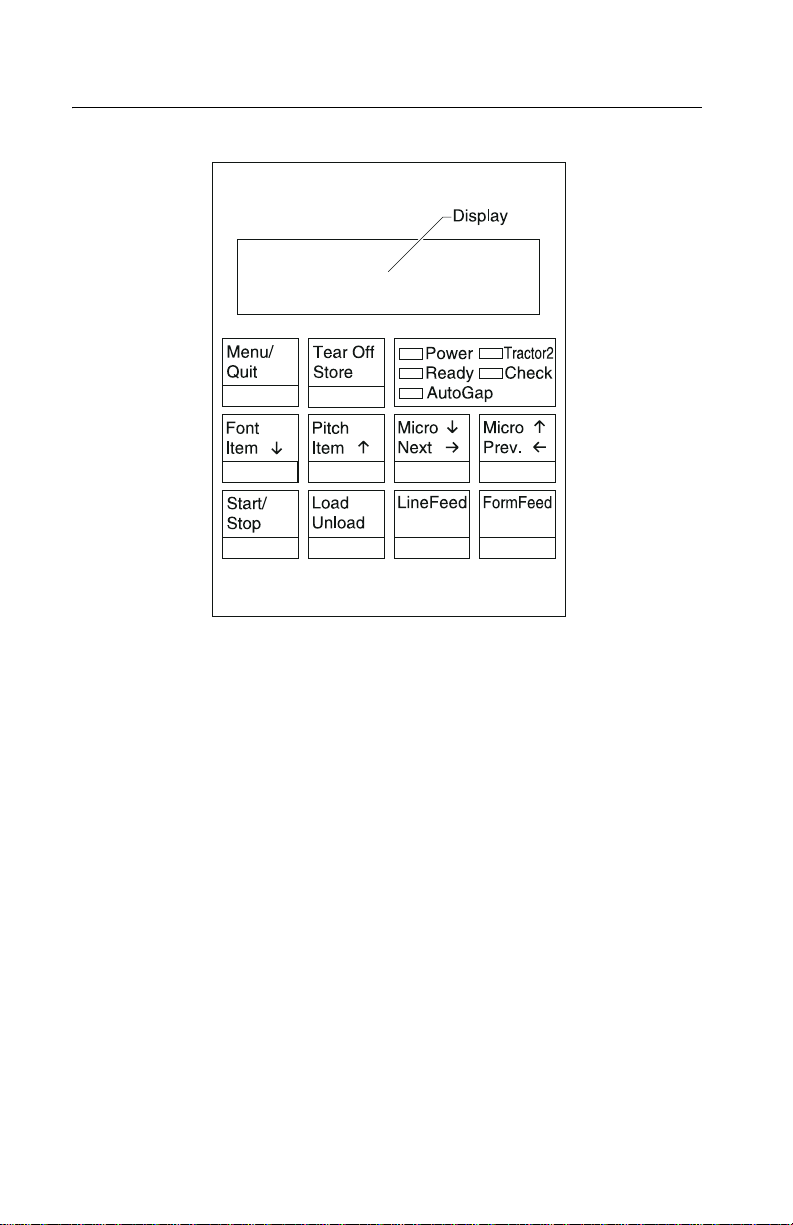
Using the operator panel
This section provides a brief description of the operator panel
buttons, lights, and settings. Refer to the User’s Guide for additional
information.
Note: Application software may allow the user to operate the printer
from a computer. Changes made to the printer settings from a
software application override settings made from the operator panel,
with the exception of the Font and Pitch Lock features.
Changeable printer functions include:
• Set Top of Form
• Tractor selection
• Character options
• Paper handling options
• Interface options
• Emulation options
• Macro definition and selection
• Pri n t tests
• Auto Gap functions
General inf ormation 1-5
Page 18
4227-300
Using the function menus
Use the Item ↓ and Item ↑ buttons to move through the menu and
option directories. Press Next → to move away from the Main Menu
to the subordinate directories and choices. Press Prev. ← if you want
to go back in a menu or return to the Main Menu.
1-6 S ervice Manual
Page 19

4227-300
Sett ing printer functions
1. Press Start/Stop.
2. Press Menu to enter the function menu.
3. Press Item ↓ or Item ↑ until the function menu you want
appears on the display.
Note: The selectable function menu is different depending on the
selected data stream mode (IBM PPDS or Epson emulation) and the
Interface mode (Parallel, RS-232 or RS-422).
4. Press Next → to enter that menu item.
5. Press Item ↓ or Item ↑ until the value you want appears on the
display.
6. Press Store to save the selected value.
Note: The currently selected default value is displayed with an
asterisk (*).
If you want to change the optional value in another function menu,
repeat steps 3 through 5. Otherwise, go to the next step.
7. To print the function setting, press Item ↓ or Item ↑ until the
Print Settings message appears on the display.
8. Press Start/Stop to print the current setting values.
9. Press Quit to exit the function menus.
Note: If you have changed any settings, the printer performs a
Power-On Self Test. For more information, see “Power-On Self Test
(POST)” on page 3-1. If you did not change any settings, the printer
enters the not-ready state.
General inf ormation 1-7
Page 20
4227-300
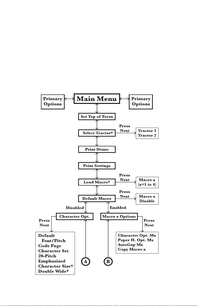
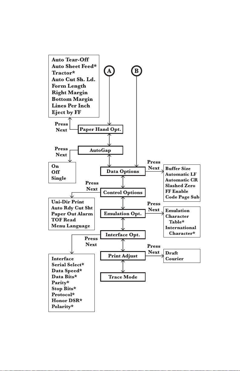
Overview of function menus
Use the Item ↑ and Item ↓ buttons to move through the menu and
option directories. Press Next → to move away from the Main Menu
to the subordinate directories and choices. Press Prev . ← if yo u w a nt
to go back in a menu or return to the Main Menu.
Menu items marked with an asterisk (*) may not appear on the
operator panel, depending on the printer settings or what printer
options are installed.
1-8 S ervice Manual
Page 21
4227-300
General inf ormation 1-9
Page 22

4227-300
Buttons
When using the function menus, press Item ↓ or Item ↑ to scrol l
through the menu items. Press Next → or Prev. ← to move to the
next, or previous menu level.
Press To
Menu Enter the function menu. The printer goes
Quit • Exit the function menus.
Tear Off • Advance the forms to the tear-of f posi tion.
Store Save the values selected in the menus.
Font Select a font.
Item
↓ Scroll down.
Pitch Select a pitch.
Item
↑ Scroll up.
Micro
↓ Advance the forms down 0.35 mm (1/72 in.).
→ Scroll forward.
Next
Micro
↑ Advance the forms up 0.35 mm (1/72 in.).
Prev.
← Return to the previous function menu.
Start/Stop • To return to Ready and to Start/Stop.
offline.
• Run a Powe r-On Se l f Test (POS T ).
• Retract the forms to the Top-of-Form (TOF)
position when the forms are at the tear-of f
position.
• Load the forms to TOF position wit h the
ready light on.
Load/Unload • Load paper (cut or con ti nuous forms) to t he
LineFeed Advance the paper to the next line .
FormFeed • Advance the paper to the TOF position on
TOF posi tion.
• Retract the forms to the tractor position.
the next page.
• Load the forms to the TOF position.
1-10 Service Manual
Page 23

4227-300
Lights
Light
Power (Green) The printer power is on.
Ready (Green) The printer is online and ready to print.
Check (Yellow) Any of the following conditions may have
Auto Gap (Green) Auto Gap is on. Auto Gap automatically adjusts
Description
The foll owing conditions cause the Ready light
to turn off:
• Pressing Start/Stop
• An end-of-form (EOF)
• A paper jam
• A cover op en
• A hardwa re er ro r
• A Power-On Self Test failure
• The printer is offline.
occurred:
• An end-of-form (EOF)
• A paper jam
• A cover op en
• A hardwa re er ro r
• A data transmission error
• An interface mode error
• A Power-On Self Test (POST)
failure
the printer according to the thickness of the
paper you are usi ng.
Tractor 2 (Green) The Tractor 2 Feeder is select ed. (The Tractor
2 Feeder option must be install ed.)
General information 1-11
Page 24

4227-300
1-12 Service Manual
Page 25

4227-300
2. Diagnostic information
Start
Make a quick visual check for defects (loose or broken parts,
unplugged connectors, or paper jams).
If there is no power after turning the printer on, go to the “Power
failure service check” on page 2-25.
If an error indicator appears, go to the “Error indication table” on
page 2-1 and take the indicated action.
Run the “Print Tes t” on page 3-5 and refer to the “Error lo g” on page
3-5 for details of error indication information. If no error indication
appears, refer to “Symptom tables” on page 2-3.
Error indication table
The following table describes the service check entries for the
printer error indication codes.
When an error indication changes after you have entered a service
check, you have an intermittent problem. If this occurs, leave the
service check and go to “Symptom tables” on page 2-3.
Display Indication Description/Action
631 Machine Check
Display RAM Error
632 Machine Check
System RAM Error
Display RAM Read/Write Error. This error
is detected only duri ng PO ST. Replace the
operator panel.
System RAM Read/Write Error.
Replace the main logic board and
perform the
adjustment” on page 4-3
“Printhead-to-platen gap adjustment”
on page 4-2
“Bidirectional print
. Check the
.
Diagnostic information 2-1
Page 26

4227-300
Display Indicati on Description/Action
633 Machine Check
Timer Interrupt Error
636 Machine Check
NOVRAM Error
637 Machine Check
CA Drive Error
638 Machine Check
CA Drive Error
639 Machine Check
CA Drive Error
63B Machine Check
Key Scan Error
63C Machine Check
Auto Gap Error
Timer Interrupt Controller Error. Replace
the main logic board and perform the
“Bidirectional print adjustment” on
page 4-3
platen gap adjustment” on page 4-2
Non-Volatile Memory Read/W rite Error.
Replace the main logic board and perform
the
page 4-3
. Check the “Printhead-to-
.
“Bidirectional print adjustment” on
. Check the “Printhead-to-
platen gap adjustment” on page 4-2.
Home Timeout Error. Go to the
“Carrier
drive service check” on page 2-15.
Carrie r D rive Error .
No emitter pulse detected. Go to the
“Carrier drive service check” on page
2-15.
Carrie r D rive Error .
Carrier positioning error. Go to the
“Carrier drive service check” on page
.
2-15
Button Scanning Error.
Go to the
check” on page 2-20
Auto Gap Error.
Go to the
page 2-11
“Operator panel service
.
“Auto Gap service check” on
.
63D Machine Check
Tractor 2 HP Error
63E Machine Check
Head Thermal Error
63F Machine Check
Option RAM Error
640 Machine Check
CA Thermal Error
2-2 S ervice Manual
Tractor 2 Home Position Er ror.
Go to the
“Tractor 2 service check” on
page 2-31.
Head Thermal Sensor Error.
Go to the
service check” on page 2-28
Option RAM Read/Write Error.
Replace the 32Kb Memory Module.
Carrier Thermal Sensor Error.
Go to the
“Print wire drive failure
.
“Carrier drive service check”
on page 2-15.
Page 27

4227-300
Symptom tables
1. Select the symptom that best describes the problem.
2. Perform the appropriate action before you go to the indicated
service check.
Diagnostic information 2-3
Page 28

4227-300
Abnormal Indications
Symptom Action
All LEDs turn on but
do not turn off.
The Power LED is
on, but POST will
not run.
Disconnect the inter f ace c ab le from the p rinter and
turn the printer off and then back on. If POST now
runs correctly, the problem is in the computer or
interface cable.
Go to the
“POST service check” on page 2-24.
Abnormal print operation problems
Symptom Action
Printer will not print,
or become Ready.
Abnormal operation,
incorrect cha ra cters ,
or incorrect line
width
Printer is ready but
will not print from the
computer correctly.
Undefined or
incorrect characters
Be sure the interface cable is connected properly.
Go to the
“No print or abnormal print service
check” on page 2-19.
2-4 S ervice Manual
Page 29

4227-300
Auto Sheet Feeder problems
Symptom Action
Auto Sheet Feeder
will not feed paper.
Auto Sheet Feeder
double feeds.
Auto Sheet Feeder
has intermit tent f eed
problems.
Paper skews .
Be sure Auto Sheet Feed is set to On i n the Paper
Handling Option Men u.
Be sure the paper select lever is in the cut sheet
position.
Go to the
2-11
Isolate the problem by removing the Auto Sheet
Feeder and then feed paper using the manual
feed tray. Go to the
service check” on page 2-13
6XX Error indications
Symptom Action
6XX Machine
Check is displayed.
Turn the printer off and then on.
Go to
“Auto Gap service check” on page
.
“Auto Sheet Feeder (ASF)
.
“Error indication table” on page 2-1.
Diagnostic information 2-5
Page 30

4227-300
Paper feed problems
Symptom Action
Paper Empty
Add Paper
is displayed with
paper in the printer.
Print operation starts
without paper.
Load/Unload
does not function.
Form feed length is
not correct.
Load/Unload
functions with cut
shee ts in us e.
Paper feeds, but
Auto Loading does
not work.
Be sure the Paper Empty Sensor is not blocked.
There may be a problem with the Paper Select
Sensor. Go to the
on page 2-21
Be sure the Paper Sel ect leve r is in the correct
position.
There may be a problem with the Paper Select
Sensor. Go to the
“Paper feed service check”
.
“Paper feed service check”
on page 2-21.
Be sure the Paper Select lev er is in the cut sheet
position.
Be sure Auto Cut Sheet is enabled in the Paper
Handling Option Menu.
Go to the
“Paper feed service check” on page
2-21.
2-6 S ervice Manual
Page 31

4227-300
Symptom Action
Lower feed roll shaft
rotates, but paper
does not feed.
Pressing Form Feed
does not feed paper.
Abnormal noise
while fe eding
Paper jams, skews,
or creases.
Incorrect or no li ne
spacing: wider,
narrower, or
overlapping lines.
Incorrect Top of
Form positioning
Be sure the Paper Select lever is in the correct
position.
Go to the
2-21
“Paper feed service check” on page
.
Diagnostic information 2-7
Page 32

4227-300
Operator panel problems
Symptom Action
Start/Stop does not
function but no error
is indicat e d.
Turn the printer off and then back on.
Go to the
page 2-20
Only the Power light
comes on.
One or more b utto ns
do not function.
One or more lights
do not function.
Blank displa y
Cover open
displayed.
Power Problems
Symptom Action
When the power
switch is on, the
Power light does not
come on or the
printer does not
start.
“Operator panel service check” on
.
Check the contin uity of the power cor d
and the voltage of the electrical outlet.
Go to the
check” on page 2-25
“Power failure serv ic e
.
The Power light
blinks or chan ges
intensity.
2-8 S ervice Manual
Page 33

4227-300
Print quality problems
Symptom Action
No print, but carrier
moves as i f printi ng.
Be sure the printhead cables are not loose or
damaged.
Be sure the interface cable i s connected properly.
Check the ribbon cartridge for binds or damage.
Go to the
“Print wire drive failure service
check” on page 2-28.
Print density is light. If the ribbon has reached its end of life or is worn,
the ribbon cartridge needs to be replac ed.
Unev en print densit y
across th e print line
Specific dots
missing.
Go to the
2-11
drive service check” on page 2-30
Be sure the printhead cables are connecte d
correctly to the printhead and the sub logic board.
Clean the printhead.
Set the Auto Gap to On in the user menus and run
the print test. If the print i s light at one edge and
uniformly gets darker across the page to the other
edge, perform the
adjustment” on page 4-2
Go to the
check” on page 2-28
“Auto Gap service check” on page
. If no problem is found, go to the“Ribbon
.
“Printhead-to-platen gap
.
“Print wire drive failure service
.
Scattered ink,
smearing, blurred
characters
Fuzzy print
Clean the printhead nose.
Clean the ribbon guide and shi eld.
If the ribbon has reached i ts end of life or is w orn,
the ribbon cartridge needs to be replac ed.
Go to the
“Print quality service check” on page
2-27.
Diagnostic information 2-9
Page 34

4227-300
Symptom Action
Wavy vertical lines,
unev en left margin,
or character width is
reduced.
Clean and lubricate the carrier shaft.
If the carrier drive belt is worn or broken, replace
the carrier unit. Perform the
adjustment” on page 4-3
Go to the
page 2-15
Ribbon feed problems
Symptom Action
Ribbon comes off,
becomes loose or
folded, or jams.
Ribbon feeds
correctly but is noisy.
Check the ribbon cartridge f or binds or damage.
Go to the
page 2-30
“Bidirectional print
.
“Carrier drive service check” on
.
“Ribbon drive service check” on
.
2-10 Service Manual
Page 35

4227-300
Servi ce checks
Auto Gap service check
Theory of operation
The Auto Gap motor and Gap Home sensor automatically set the
printhead gap for the thickness of paper being used by rotating the
eccentric carrier shaft. The printer detects maximum gap with the
Gap Home sensor, and minimum gap by driving the printhead
against the platen. In addition to compensating for the thickness of
the paper itself, the printer must increase the air gap for thicker
papers.
With Auto Gap On, the following occurs:
• POST
• Auto Gap resets.
• The printer unloads paper, if it is loaded, to prepare to measure
the travel span.
• The Auto Gap motor drives the printhead against the platen to
measure the total travel span.
• Auto Gap resets again, to make room for paper to be loaded.
• The paper feeds to the print line.
• The Auto Gap motor drives the printhead against the paper to
measure the total travel span minus the paper thickness.
• Auto Gap resets again.
• The printhead moves to the appropriate gap position for the
installed paper.
• The Ready LED comes on, the carrier centers, and the paper
moves to the tearoff position.
Diagnostic information 2-11
Page 36

4227-300
Auto Gap can be set to off to reduce time-to-print if the printer is
always used with a single type of paper. With Auto Gap off, the ga p
can be set to Manual Position 1 (thinnest paper) to 7 (thickest
paper). With Auto Gap off, Single Au to Gap ha s t wo s e l e c tions:
• Fixed—The printhead gap is never changed.
• Open—The gap is opened when loading form s.
Note: If there is a 63C Auto Gap Error, the Gap Home sensor did
not detect that the carrier shaft homed, or it detected that the carrier
shaft homed at the wrong time.
FRU Action
1 Auto Gap Sensor Inspect the Gap Home fl ag on the end of the
carrier shaft and make sure it blocks the
sensor when the gap is at its largest. Turn the
printer on and watch the carrier shaft and the
Gap Home flag. If the sh aft rotates before the
error occurs, the sensor may have failed.
Perform the Sensor 2 Test in the Servic e M enu
and test the Gap Home sensor.
2 Auto Gap Motor
Gear Train
2-12 Service Manual
If the carrier shaf t does not rotate, l ook for an
Auto Gap motor or Auto Gap gear train
problem. Disconnect CN20 from the main logic
board.
Check the resi s t a n ce of pi ns :
1 and 5, 2 and 6, 3 and 5, and 4 and 6.
All resistances should be 180
No pin should have continuit y to ground.
If there is no 63C Auto Gap Error but there is a
gap problem (l ight print or no print, or paper
catching on the printhead or ribbon shield),
enter the user menus to make sure the gap
settings are a ppropriate for the paper being
used. If Auto Gap is off, Manual Posi tion 1
should be used only wi th si ngle-part 16 lb. or
20 lb. forms. Refer the customer to the User's
Guide for the appropriate Manual Position
settings.
± 5 ohms.
Page 37

4227-300
Auto Sheet Feeder (ASF) service check
Auto Sheet Feeder principles of operation
The Auto Sheet Feeder (ASF) feeds into the cut sheet paper entry
throat. To use the ASF:
• The Paper Select lever must be set to Cut Sheet.
• Auto Sheet Feeder must be selected in the display menu.
Continuous forms can be used with the ASF installed by moving the
paper select lever to Continuous Forms and pressing Start to feed
the continuous forms to the first print line.
The ASF contains no electrical parts. It is driven from the gear on the
inside of the printer’s right side frame.
The combination lock mechanism is a clutch that causes the ASF
pick rollers to feed only one sheet of paper at a time. When Auto
Sheet Feeder is selected on the Paper Handling Options Menu, the
cut sheet paper drive reverses itself for a short distance during
paper loading. This engages the clutch and engages the paper pick
rollers, which feed the top sheet from the cut sheet paper stack. The
sheet is fed about 5 inches (125 mm) and the paper path briefly
reverses again; this disengages the clutch and the pick rollers. The
sheet is then fed to the print line by the ASF’s upper and lower feed
rollers and the printer’s lower f eed rollers. Although the ASF pick
rollers continue to turn as the paper is fed, their drive is disengaged
and they are actually being turned by the paper.
FRU Action
1 Paper Select
Sensor
With the Paper Select lever in the Cut Sheet
position, do the f ollowing:
• Try to load a sheet with Load/Unload.
(This button should not work.)
• If the paper loads , go t o t he “P OST service
check” on page 2-24
Diagnostic information 2-13
.
Page 38

4227-300
FRU Action
2 Paper Feed If the paper does not feed, do the following:
• Remov e the ASF.
• Be sure the base prin ter feeds paper
correctly.
• If it does not f eed paper correctly, go to the
“Paper feed service check” on page
.
2-21
3 Gear Tr ain Be sure the ASF driv e gear on the insi de of the
4 Combination Lock
Mechanism
5 Left and Right
Hoppers
6 Pick Rollers
Paper Guides
Feed Rollers
printe r’s rig h t fra m e ro ta te s.
Inspect the right si de gear train for damage or
debris.
Remove the ASF right cover and ensure that
all gears are in good condition.
Install the ASF and press FormFeed.
If the pick drive shaft does not rotate, replace
the combinati on lock mechanism.
If the ASF pick rollers rotate b ut a si ngle sheet
is not pick ed, inspect the spri ngs and corner
separators on the left and right hoppers .
Make sure the paper load lever is in the correct
position.
Paper skew can be cause d by worn, dirty, or
binding pi ck and feed rollers . Remove the Auto
Sheet Feeder, load paper, and hand cycle the
feeder while observing the pick and feed
rollers. If the skew problem is in the base
machine, examine all feed rollers for wear.
2-14 Service Manual
Page 39

4227-300
Carrier drive service check
Note: When a 637, 638, or 639 error is detected while printing,
verify that the same error is detected after removing jammed paper
and checking that the ribbon guide is in place.
FRU Action
1 637, 638, 639
CA Drive Error
2640
CA Thermal Error
Carrier positioning error.
Inspect the f o llowing:
• Tension pulley plate
• Carrier
• Carrier belt
Loosen and tighten the tension pulley pl ate
screws to make sure the carrier belt is tight.
Disconnect CN9 and move the carrier
manually from le ft to right and check f or
smooth movement.
With CN9 disconnected, check for 5 to 8 ohms
between pins 1 and 2 on the motor c able. If the
reading is incorrect, replace the motor.
Check for motor pins shorted to the housing. If
you find a pin shorted to the housing, replace
the motor.
If no problems ar e found, replace the carrier
motor.
The printer has stopped to protect the carrier
motor from overheating. Normally this will not
occur until after several hours of continuous
heavy use in a warm environment, and only
then after going through several stages of
thermal slowdown.
Wait for the machine to coo l and see if the
error goes away.
If the machine was not being used heavily
before the er ror occu rred, or if the error returns
when the machine is cool, repl ace the carrier
motor.
Diagnostic information 2-15
Page 40

4227-300
Intermittent problem service check
FRU/Symptom Action
1 The machine
sometimes fails
before POST is
complete.
Check for the follo w ing:
1. Loose connectors. Reconnect all connector s
to the main and sub logic boards.
2. Electrical noise or static discharge.
Check the following items:
• Power supply ground
• Machine frame ground
• Printer inter face cable is grounded and
shielded.
3. Intermittently lo w voltages . Check for ac and
all dc v olt ages and short-c ircuit s o n the m ain
and sub logic boards.
a. Check the electrical voltage and ensure
that it is within tolerance.
b. Check the continuity of the power
cord.
c. Disconnect the power supply cable
from the connectors CN11 on the
main logic board and CN1 on the sub
logic board. Turn the printer power on
and check all dc out put voltages at
CN11 and CN1.
Ensure the output v oltages are:
CN11-1 (+40 ±4 V dc) & CN11-3 (GND)
CN11-2 (+40 ±4 V dc) & CN11-3 (GND)
CN11-5 (+5 ±0.5 V dc) & CN11-6 (Signal GND)
CN 1-1 (+40 ±4 V dc) & CN1-3 (GND)
CN 1-2 (+40 ±4 V dc) & CN1-3 (GND)
CN 1-5 (+5 ±0.5 V dc) & CN1-6 (Signal GND)
2-16 Service Manual
If the voltages are not correct, replace the
power supply unit.
If the fa il ure remains, replace the main logic
board and sub logic board.
Note: When replacing the main logic board,
always perform the
adjustment” on page 4-3
“Bidirectional print
and the
“Printhead-to-platen gap adjustm ent” on
page 4-2.
Page 41

4227-300
FRU/Symptom Action
2 M achi ne power
sometimes turns
off.
3 Intermittently poor
print quality.
The cause of this problem may be that the
power circuit is failing, or the wiring is
intermittently open. Check the following in
sequence:
1. Check t he electrical voltage and be sure it is
within tolerance.
2. Check th e conti nuity of the power cord.
3. D isconnect the power supply cable from the
connectors CN11 on the main logic board
and CN1 on the sub logic board. Turn the
printer power on and ch eck all dc output
voltages at CN11 and CN1.
Be sure the output voltages are as foll ows:
CN11-1 (+40 ±4 V dc) & CN11-3 (GND)
CN11-2 (+40 ±4 V dc) & CN11-3 (GND)
CN11-5 (+5 ±0.5 V d c ) & CN11- 6 (Signal GND)
CN 1-1 (+40 ±4 V dc) & CN1-3 (GND)
CN 1-2 (+40 ±4 V dc) & CN1-3 (GND)
CN 1-5 (+5 ±0.5 V dc) & CN1-6 (Signal GND)
If one of the voltages is 0, go to the “Power
failure service check” on page 2-25. If the
voltages ar e not 0 b ut ar e incorrect , repl ace the
power supply unit.
Do the following:
• Remove paper jam s fr om the paper path.
• C lean all feed roll er surfac e s .
• Clean the ribbon shield and printhead.
• Clean the platen surface.
• Install the ribbon cartridge correctly.
• If the ribbon end of life has been reached,
have the cu stomer replace the ribbo n
cartridge.
Diagnostic information 2-17
Page 42

4227-300
FRU/Symptom Action
4 The previous
suggestions have
not corrected the
problem
5 Problem occurs
only in specific
customer
applications.
The service check has not defined the f ailure,
or the machine is ha ving intermittent failures.
The following may cause undefined or
intermittent failures:
1. Customer’s electrical vo lt age. Be sure th at i t
is within the tolerance.
2. Loose connector pins or keys that f a il to
contact.
Check the following:
a. Reconnect the connectors of all FRUs
and printer interface cables.
b. Check the continuity of the line cord.
3. Electrical noise.
Check the following:
a. Power supply grou nd
b. Machine frame ground
c. Printer interface cable is grounded
or shielded.
4. Undefined data in customer appl ications.
Check the baud rate at the controller. Check
that the printer in ter face cable matches the
printer.
Perform the Trace Print (hexadecimal printing)
by the following procedure and check the data
streams.
1. Press Menu.
2. Press Item
3. Press Start.
4. Have the customer print the failing job.
5. To stop printing, turn the power switch off.
↑ to display Trace Mode.
2-18 Service Manual
If the failure still occurs, perform the
“Bidirectional print adjustment” on page
and the “Printhead-to-platen gap
4-3
adjustment” on page 4-2.
Page 43

4227-300
No print or abnormal print service check
FRU/Function Action
1 C arrie r If the carri e r m ove s, but nothing is print e d, go
to the
“Print wire drive failure service
check” on page 2-28.
2 Configuration Enter the user menus and be sure the correct
emulation (IBM/EPSON) and interface
(parallel/serial) are selected.
If the printer is serial ly attached, be sure the
RS232/RS422 swit ch is in the correct position,
and the host communications paramet ers are
correct.
3 Main Logic Board If the Print Test does not print, or prints
incorrectly, do the following:
• Replace the main logic board.
• Perform the
adjustment” on page 4-3
“Printhead-to-platen gap adjustment” on
page 4-2
“Bidirectional print
and the
.
Diagnostic information 2-19
Page 44

4227-300
Operator panel service check
Note: Press any button except Start/Stop, Load/Unload, or
FormFeed. If Operator Panel Disabled is displayed, unlock the
operator panel by powering up with the Micro↑ and Micro↓ keys
pressed. Use the same procedure to re-lock the panel after service
is complete.
FRU Action
1 Operator Panel If there is a 631 Display RAM Error, replace the
2 Printer Cable
Operator Panel
3 Cover Switch If Cover Open is displayed, check the cover
4 Main Logic Board If the symptom has not changed, replace the
operator panel.
If there is a 63B Key Scan Error, one or more
buttons are being detected as pressed during
power-up.
Replace the oper ator panel.
During power-up, all LEDs and all LCD pels
should turn on briefly.
Enter the Service Menu and perform the
Button Test. If there are missing or extra pels
displa y ed, or i f an y of these t ests fail, chec k the
condition and continuity of the operator panel
cable.
Replace the cable or the operator panel.
switch.
Jumper the cover swit ch connector on the
operator panel. If Cover Open is displayed,
check the condition and continuity of the
operator panel cable. Repl ace the cable or the
operator panel.
main logic boar d.
2-20 Service Manual
Page 45

4227-300
Paper feed service check
Note: If the problem is frequent jams or paper creases, verify that
the paper is neither very thick nor very thin. If necessary refer the
customer to the User’s Guide for specifications of acceptable
papers.
FRU/Symptom Action
1 Auto Sheet
Feeder
If the Auto Sheet F eeder is inst alled, remo v e it.
Enter the Paper Handling Options Menu and
set ASF to off. Verify that the machine works
correctly witho ut the ASF installed.
If the printer fails only with the Auto Sheet
Feeder installed, go to the
“Auto Sheet
Feeder (ASF) service check” on page
.
2-13
2 T ractor 2 If the Tractor 2 option is instal led, remove i t.
Verify that the machine works correctly without
Tra ctor 2 installed.
If the printer fails only with Tractor 2 installed,
go to the
2-31
3 Paper Feed Moto r If there is no paper motio n, di sconnect the
paper feed motor connector CN10 from the
main logic board.
Check the resis tance of pins:
CN-1 and 6, 2 and 5, 3 and 6, and 4 and 5.
All resista nces should be 5.8
pin should have continuity to ground.
“Tractor 2 service check” on page
.
± 0.5 ohms. No
Diagnostic information 2-21
Page 46

4227-300
FRU/Symptom Action
4 Gear Train and
Paper Feed Motor
Remove all paper from the machine.
Press FormFeed several times and examine
all rotating parts to find the problem.
For better visibility, remove the covers and
reconnect the operator panel to t he main logic
board.
The upper and lower f eed r ollers and the upper
and lower pi nch rollers should al l be clean and
in good condition, and should all rota te duri ng
Form Feed.
To turn the gear train manually, turn the right
end of the lower feed roller shaf t with a 6 mm
wrench.
2-22 Service Manual
Page 47

4227-300
FRU/Symptom Action
5 PE Sensor
TOF Sensor
PSet Sensor
Jam Sensor
The printer has four sensors in the paper path ,
plus one which detects the position of the
Paper Select lev er. Enter the Service Menu
and perform the sensor tests.
• PE Sensor—Rounded flag, detects the
presence of paper at the platen.
• TOF Sensor—Sharp flag, det ermines TOF
at paper load.
• PSet Sensor—Paper set, detects presen ce
of paper in the tractors and looks for end of
forms.
• Jam Sensor—Senses the ho les in the paper
and detects paper jams b y the lack of paper
movement.
When the PSet sensor detect s EOF, it lets
printing continue to the bottom of the form.
When the PE sensor detects no paper, it stops
print within a few lines.
The jam sensor stops printing after about
50 mm of no signal change; for example, if 50
mm of pinfeed is re mo ved from a sheet, the
sensor stops printing. Less than 50 mm will
probably be ign ored. Therefore, the paper
motion must hav e st opped f or the equiv alen t of
about 12 printed lines to cause a jam.
If either the PE or the PSet sensor detects no
paper during print, printi ng stops at the end of
the current page.
6 Paper Select
Sensor
The Tractor 2 option also has PSet and Jam
sensors on the left tractor.
Enter the service menu and perf orm the sensor
tests.
Replace any failed or damaged sensors.
Enter the Service Menu and perform the
Sensor Test 2 for “Lever.”
Move the Paper Select lever to test the sensor.
Replace any sensor i f failed or damaged.
Diagnostic information 2-23
Page 48

4227-300
FRU/Symptom Action
7 Operator Panel If paper does n ot move at all, verify the
FormFeed button is wo rkin g c orrect ly by
performing the Service Menu Button Test.
8 Main Logic Board If no other problem is found, replace the main
logic board.
Perform the
on page 4-3
adjustment” on page 4-2
“Bidirectional print adjustment”
, and “Printhead-to-platen gap
.
POST service check
FRU Action
1 Power Disconnect t he parallel or serial cabl e and turn
2 Operator Panel If the power supply fan turns on but no LEDs
3 Main Logic Board If the Power LED turns on but POST does not
4 Printer Cable If POST completes, reconnect the paralle l or
the power on.
If there is no printer activity, go to the
failure service check” on page 2-25.
light, go to the
check” on page 2-20
complete, replace the main logi c board.
Perform the
on page 4-3
“Operator panel service
.
“Bidirectional print adjustment”
and check the
“Printhead-to-platen gap adjustm ent” on
page 4-2.
serial cable and turn power on again.
“Power
2-24 Service Manual
If POST now fails, there is a problem with the
cable, or the parallel connector on the main
logic board.
Page 49

4227-300
Power failure service check
For more information see “Voltage, ground, and continuity readings”
on page 1-2.
FRU Action
1 Operator Panel If the operator panel or cab le is damaged or
2 Power Supply
Fuse
disconnected, the machine is completely
inoperable, except for the power supply fan
noise.
If the power LED is not on steady, check the
cable conti nuity and replace the cable or the
operator panel.
If the printer is completely inoperable,
disconnect the power cables from the main
logic board (CN11) and the sub logic board
(CN1).
Turn the power on and measure
+5 ± 0.5 V dc at the sub logic board cable
CN1-5 and +40 ± 4 V dc at CN1-1 and CN1-2.
If there is no voltage, check the internal fuse
before repl acing the power supply.
A 634 Power Failure indicates th at t he +5 V dc
is OK but the +40 V dc is not. P o wer the printer
off, wait 10 seconds, and power back on. If the
634 reappears eith er the power suppl y has
failed or ther e is a short in a motor that uses
+40 V dc.
Diagnostic information 2-25
Page 50

4227-300
FRU Action
3 Ribbon Motor
Paper Feed Motor
Carrier Motor
Sub Logic Board
4227-300 Carrier
Motor Cooling
Fan
4 Printhead Cables
Printhead
5 Main Logic Board If all the above item s have been examined and
Disconnect t he carrier motor (CN9 and CN15),
the paper feed motor (CN10), the ribb on m otor
(CN19) and the (4227-300) carrier motor
cooling f an (CN17) from the main logic board,
and disconnect the power connector CN-1
from the sub logic board. Turn the power on
again. If there i s sti ll a power problem, replace
the main logic boa rd.
If the machine post s a different er ror, one of
these items i s shorted and is holding do wn the
+40 V dc line. Reconn ect them one at a time,
turning the printer on in between each
connection.
Replace the i tem that causes t he po w er f ail ure.
Disconnect the printhead cables from the sub
logic board and turn the print er on. I f the po wer
LED lights correctly only with the printhead
cables disconnected from the sub logic board,
there is a short in the printhead or print head
cables.
there is still a power problem, replace the main
logic board. (Retain the old board for
reinstal lation if the problem is not fixed. )
Perform the
on page 4-3
“Bidirectional print adjustment”
and check the “Printhead-to-
platen gap adjustment” on page 4-2.
2-26 Service Manual
Page 51

4227-300
Print quality service check
FRU Action
1 Ribbon and Shield Be sure the ribbon is not worn and feeds
smoothly when the knob is turned. Inspect the
ribbon shield for dirt or damage.
2 Ribbon Drive Be sure the ribbon drive post rotates when
printing.
3Auto Gap
Check the
“Printhead-to-platen gap
adjustment” on page 4-2. If Auto Gap is off,
be sure the manual position setting is
appropriate for the paper used.
Auto Gap Motor
Bracket
4 Printhead Cabl es Inspect both ends of the printhead cables fo r
5 Carrier Belt
Adjustment
6 Carrier Movement With the power off, manually move the carrier
7 Bidirect io nal Pr in t
Adjustment
8 Carrier Motor The carrier motor should turn smoothly and
9 Paper Feed
Gears
10 Paper Feed Motor The paper feed motor should turn smoothly
11 Tractors Inspect the tractors for damage or looseness.
If the failure remains, replace the Auto Gap
motor bracket.
proper connection.
Loosen and tighten the tension pulley pl ate
screws to make sure the carrier belt is tight.
from side to side to inspect for drag or binds.
Perform the
on page 4-3
quietly when printing.
Inspect the paper feed ge ars for wear and tear.
and quietly when printing.
“Bidirectional print adjustment”
.
12 Feed Roller
Surfaces
Inspect the feed roller surf aces for di rt or wear.
Diagnostic information 2-27
Page 52

4227-300
Print wire drive failure service check
FRU/Symptom Action
1 Missing Dots
Car r i e r m ove s,
but there is no
printing or
printhead sound.
Perform the Print Test to determine which
wires are not printing. Disc onnect the pri nthead
cables f rom t he sub l ogic bo ard and chec k t he
resistance for the affected wires. The
resistanc e for each wire shou ld be ar ound
8.5 ohms.
Left Bank Right Bank
Wire 1 CN3-11 & CN3-18 CN3- 9 & CN3- 4
Wire 2 CN4-11 & CN4-20 CN4- 9 & CN4- 2
Wire 3 CN3-13 & CN3-16 CN3- 7 & CN3- 6
Wire 4 CN4-13 & CN4-18 CN4- 7 & CN4- 4
Wire 5 CN4-15 & CN4-16 CN4- 5 & CN4- 6
Wire 6 CN4-17 & CN4-14 CCN4- 1 & CN4-8
Wire 7 CN3-15 & CN3-14 CN3- 3 & CN3- 8
Wire 8 CN4-19 & CN4-12 CN4- 3 & CN4-10
Wire 9 CN3-17 & CN3-12 CN3- 5 & CN3-10
2-28 Service Manual
Note: 4227-300 connectors will be
CN1 and CN2.
If the resistance for the affected wires i s
incorrect , di sconnect th e print head cab l es fro m
the printhead and measure the resistanc e of
the printhead for the same wires. The
resistance should be around 7.9 ohms.
• If the resistance is correct, replace the
printhead cabl es.
• If the resistance is incorrect, replace the
printhead.
Page 53

4227-300
FRU/Symptom Action
2 63E He ad
Thermal Error
3 Auto Gap If the printhead is firing, manually rotate the
4 Printhead Cables Inspect for improper connecti on or damage.
5 Sub Logic Board If there is carrier moti on but no printhead noi se,
6 Ribbon A problem with the ribbon shield can keep the
The printer has stopped to protect the
printhead from overheating. Normally this
occurs after several hours of cont inuous heavy
use in a warm env ironm ent, and only then af ter
going through severa l stages of thermal
slowdown.
Wait for the machine to coo l and see if the
error goes away.
If the machine was not being used heavily
before the er ror occu rred, or if the error returns
when the machine is cool, repl ace the
printhead.
carrier shaft during printing by pushing down
on the Auto Gap Home senso r fl ag.
If printing sta rts and i s correct, go to the
Gap service check” on page 2-11
and the printhead cab les do not appear to be
the problem, r eplace the sub logic board.
print wires too far fr om the page.
“Auto
.
Inspect the ribbon shield. When the printer is
Ready with the ribbon in stalled, make sure the
ribbon shield can float slightly front to back.
7 Printhead The printhead probab ly is not the problem if
there is no printing.
Check the winding resistances as described
above and look for open circuits or shorts
between neighboring pins.
Do not replace the printhead unless a specific
problem is f ound.
Diagnostic information 2-29
Page 54

4227-300
FRU/Symptom Action
8 Main Logic Board If no other problem is found, replace the main
logic board, ret aining the old board f or
reinstal lation if the problem is not fixed.
Perform the
“Bidirectional print adjustment”
on page 4-3 and the “Printhead-to-platen
gap adjustment” on page 4-2
.
Ribbon drive service check
In normal operation, the ribbon knob rotates counterclockwise
whenever the carrier moves to the left.
FRU/Symptom Action
1 Ribbon Drive
Gear Train
2 Ribbon Motor If printing seems normal, but the ribbon is not
Remove and insp ect the ribbon. Make sure the
knob turns with even, moderate force and the
ribbon feeds correctly.
Inspect the gear train from the ribbon motor to
the ribbon drive post.
Check the
adjustment” on page 4-2
moving, remove the ribbon and turn power on.
The ribbon driv e post should t urn se ve ra l times
during POST. Disconnect the ribbon motor
connector CN19 from the main logic board.
“Printhead-to-platen gap
.
2-30 Service Manual
The winding resistance should be
118 ohms ± 5 between pins:
1 and 5, 3 and 5, 2 and 6, 4 and 6.
Pin 5 should show an open circuit to pins 2, 4
and 6. Pin 6 should show an open circuit to
pins 1, 3, and 5.
Page 55

4227-300
Tractor 2 service check
The Tr actor 2 sensor opens dur ing installation, when its actuator
touches the printer cover. The home sensor detects the position of
the slider.
• When Tractor 2 is selected, the motor-driven Tractor 2 slider
pushes the printer sub slider cam lever to engage the printer
gear train, which drives the Tractor 2 tractors.
• When the T ract or 2 is deselected, the motor retracts the slider,
disengaging the Tractor 2 gear drive and reengaging the printer
tractors.
63D Tractor 2 HP error
The Trac tor 2 Home sen sor was never initialized after turning the printer off
and then on, or made at the wrong time.
(The same error indication is used for carrier home failure.)
FRU Action
1Tractor 2
Home Sensor
Remove the Tractor 2 and turn the printer off
and then back on again to determin e whether
the fault is in the pri nter or in Tractor 2.
If the gear teeth chatter just before the error is
displayed, replace the home sensor.
Diagnostic information 2-31
Page 56

4227-300
FRU Action
2 Main Logic Board Remove Tractor 2 from the printer but leave
the cable connected.
Make sure t he sli der (the black plastic piece
just above the right cover) moves after turning
the printer off and t hen back on. If the slid er
does not mov e after turning the printer off and
then back on:
• Make sure the slider and gear train are
properly connected an d mov e f reely with th e
power off .
• Make sur e the Tract or 2 board is receiving:
+26 V dc on CN1-1 and
+ 5 V dc on CN1-5
If not, check the cable connection and the
voltages at main logic board CN13- 1.
The upper right pin at CN13 is pin 1 (+26 V dc)
and the pin just beneath it is pin 5 (+5 V dc).
If these voltages are not present, replace the
main logic boar d.
3 Tractor 2 Motor
Board/Cable Asm
2-32 Service Manual
Check the following resistances of the Tractor
2 motor windings:
101 ± 5 ohms between pins:
1 and 6, 3 and 6, 2 and 5, 4 and 5.
If the motor is good, r eplace the board/cable
assembly.
For more information on the Tractor 2 cable
connectors, see
“Tractor 2 cable
connectors” on page 6-15.
Page 57

4227-300
Tractor 2 installed, but not shown in User Menu
Tractor 2 is selected from operator panel but the printer does not
detect Tractor 2, or detects that the Tractor 2 mechanism is not
installed.
Power the printer off and reinstall the Tractor 2. P ower the printer on
and verify the problem still occurs.
FRU Action
1Tractor 2
Board/Cable Asm.
Check the Tractor 2 sensor or the cable
connection.
The sensor actuator extends throu gh the
Tra ctor 2 cover and rests on the printer cover
when Tractor 2 is installed.
Remove the Tractor 2 cover and mak e sur e the
sensor opens when the Tractor 2 is installed.
The voltage at Tractor 2 CN1-13 should be +5
V dc with the sensor open, and 0 with it cl osed.
Replace the Tractor 2 board/cable asm if the
sensor signal is wrong.
For more information on the Tractor 2 cable
connectors, see
“Tractor 2 cable
connectors” on page 6-15.
2 Main Logic Board Check the cable connection from Tractor 2 to
the printer.
If possib le, try the Tractor 2 with anot her printer
to determine if the problem is the Tractor 2
board/cable assembly or the printer main logic
board.
Diagnostic information 2-33
Page 58

4227-300
Paper feed problems
FRU Action
1 Tractor 2 On the printer, make sure the Tractor 2 driving
gear turns f reely when t he white sub sli der cam
is not pressed. B e sure t he driv ing gear does
not move when the sub slider cam behind the
gear is pressed.
Remove Tract or 2 from the printer and remove
all paper. With the paper sel ect lev er in the
continuous forms position, press LineFeed;
the tractors should rotate.
Press the sub slider cam below the ASF/
Tractor 2 drive gear and press LineFeed
again; the tractors should not rot ate but the
drive gear should.
Check the condition of the pin feed belts. With
the power off, make sure the slider does not
bind.
Verify:
• When the slider is t o the rear, the white gear
drives the tractors.
• When the slider is t o the f ront, the gear and
tractors are not connected.
Remove the Tractor 2 cover and reinstall
Tractor 2 in the printer (if necessary remove
the printer covers also) . Note that the small
idler gear just below the slider is hel d in pl ace
by the cover; w ith the cover removed it will
tend to move off the stud. Also note that when
operating the Tractor 2 with the printer cov er
remov ed, the Tractor 2 sensor must be held
open.
2-34 Service Manual
Turn the printer on and look for mechanical
problems.
For more information on the Tractor 2 cable
connectors, see
connectors” on page 6-15
“Tractor 2 cable
.
Page 59

4227-300
3. Diagnostic aids
The printer contains self tests to help find and solve problems. Yo u
do not need to connect the printer to a computer or terminal to run
these tests.
Types of self tests are as follows:
• Power-On Self Test (POST)
• Hex Trace Mode (a computer or terminal is needed)
• Print Tests
• Error Log
Power-On Self Test (POST)
The Power-On Self Te sts diagnose the basic hardware printer
functions and initialize the default value settings. POST star ts
automatically when power to the printer is turned on, or when the
printer receives an INIT signal from the controller.
• The power supply fan comes on.
• LED Test —A ll LEDs turn on bri efly.
• LCD Te st—Al l pels of the display are activated twice, and then
"initialize" is displayed.
• RAM Test—Checks that the CPU can write/read the RAM.
• ROM Test— Checks that the ROM data is correct.
• Timer/Interrupt Controller Test—Checks that this function is
working.
• Button Scan Test—Scans all operator panel buttons.
• NVRAM Te st— Checks that the NVRAM data is correct.
• The ribbon motor feeds ribbon.
• The carrier moves to the left side frame, and then back to the
right.
• The auto Gap sequence occurs.
If any errors occur during the POST tests, an error indicator shows
which test failed. See “Start” on page 2-1.
Diagnostic aids 3-1
Page 60

4227-300
Hex trace m ode
The hex trace mode can help test and troubleshoot programs. You
can use the hex trace procedure to get a hexadecimal printout of the
data stream sent to the printer. All data, including control and
character data, print in hexadecimal instead of ASCII.
To activate hex trace mode:
1. Press Menu.
2. Press Item ↓ until Trace Mode appears on the operator panel.
3. Press Start.
Hex trace mode sample
3-2 S ervice Manual
Page 61

4227-300
Interfac e sel ect io n
Serial or parallel attachment can be selected from the User Menu
under Interface Options. If serial attachment is selected, RS-232 or
RS-422 can be selected with the switch that is accessible through
the rear cover. Serial attachment parameters are set in the Interface
Options menu.
Operation with the top cover removed
After you remove the top cover, the printer can be operated for
service purposes by positioning the cover near the main logic board
and reconnecting the operator panel cable. The ribbon cover must
be in place on the top cover. Or, you can remove the operator panel
and cable, jumper the two pins of the ribbon cover sensor connector
CN1 together on the back of the panel, and reconnect the operator
panel flex cable to the main logic board.
Note: Printing without the top cover affects print quality and may
cause paper jams, since the upper feed rollers on the ribbon cover
do not help restrain and feed paper.
Service Menu
Enter the Service Menu by pressing Menu/Quit during POR.
Release the button when the carrier strikes the left side frame. Exit
the Service Menu by pressing Menu/Quit.
• Sensor Test 1: Tests PSet, Jam, PE & TOF sensors.
• Sensor Test 2: Tests Paper Select, Gap Home, and Cover
sensors.
These tests display an underline (_) if the sensor is open or a block
(■) if the sensor is blocked. Use paper, tools, or fingers to block and
unblock the sensors to verify that each is functional. Return to the
Service Menu by pressing Menu/Quit.
Diagnostic aids 3-3
Page 62

4227-300
Button Test
Pressing each operator panel button causes the alarm to beep.
Pressing multiple buttons simultaneously results in no beep. Return
to the Service Menu by pressing Menu/Quit.
Factory Setting
Factory Setting allows the selection of the default page length and
code page from U.S. defaults (11", Code Page 437, Character Set 1)
to Non-U.S. defaults (12", Code Page 850, Character Set 2).
Printhead Bank
This allows the 18-wire printhead to be set to use the left bank only,
the right bank only, or both banks (default). This allows the printer to
continue to print with a damaged printhead or cable.
Jam/PSet Sensor Test
This test enables or disables the PSet and Jam sensors on the left
tractor.
Impact force
Impact force enables the striking force of the printhead pins to be
changed. Three selections are possible.
• Normal Auto—This is the default value. Impact force of the
printhead pins is adjusted automatically for paper thickness.
• High—This is the highest impact force and overrides the
Normal Auto selection. High pin force is used to obtain clearer
print on medium thickness forms. Leaving the printer in High
can damage the printhead, especially if printing on single-sheet
forms.
• Normal 1P—Disables the automatic setting of the impact force.
Normal 1P is used to print in normal force when thicker print
media is used, such as labels.
Log clear
Clears the error log.
3-4 S ervice Manual
Page 63

4227-300
Print Test
The Print Test prints:
• The ASCII character set
• A line from each print wire
• The bidirectional print alignment pattern
• The contents of NVRAM
• The error log
Other print tests
The following print tests are accessed outside the Service Menu:
• A draft only 8-inch-wide continuous print test. This test is
activated by turning the printer on with the Load/Unload and
LineFeed buttons pressed.
• A draft only 13.6-inch-wide continuous print test. This test is
activated by turning the printer on with the LineFeed and
FormFeed buttons pressed.
Note: These tests print a running page count at the bottom of each
page. Use the Start/Stop button to start and stop the test. Other
buttons that are active during this test are the Micro ↓ or Micro ↑ ,
Load/Unload, LineFeed and FormFeed buttons.
Print Demo and the Print Settings page are accessed from the
user menus. Print Settings prints Macro status and paper handling
settings and prints 8 inches wide.
Error log
The Error Log printout is part of the Service M enu test pr int page.
Error indicators print on the top line of the Error Log and their
corresponding counters print below. The error indicators are the last
two digits of the "6XX Machine Check" display indication. An error
indicator 00 indicates no errors are registered in the counter. Each
new error appears in the left-most position and the previous error
indicator shifts one position to the right. If the new error indicator is
the same as the previous error indicator, the counter is increased by
1. The maximum count number for the same error is 256, and the
counter remains at this value (X'FF'). No more than 16 most recent
error indicators can be printed in the error log area.
Diagnostic aids 3-5
Page 64

4227-300
3-6 S ervice Manual
Page 65

4227-300
4. Rep a ir in fo r m a t i on
This chapter ex plains how to make adjustments to the printer and how to
remove defective parts.
Warning: Read the following before handling electronic parts.
Handling ESD-sensitive parts
Many electronic products use parts that are known to be sensitive to
electrostati c discharge (ESD). To prevent damage to ESD-sensitive parts,
follow the instructions below:
• Keep the ESD-sensitiv e part in it s original shippin g cont ainer (a specia l
“ESD bag”) until you are ready to install the part into the machine.
• Make as few mov em ents as possible with your body to prevent an
increase of static electricity fr om clot hing fibers, carpet s, and furniture.
• Put the ESD wrist strap on your wrist. Connect the wrist band to the
system ground point . This disc harges any static elect ricit y in your body
to the mac h in e.
• Hold the ESD-sensitive part by its edge connec tor shroud (cover); do
not touch its pins. If you are removi ng a pluggable module, use the
correc t to o l.
• Do not place the ESD-sensitive part on the machine cover or on a
metal table ; if you need to put down the ESD-sensi tive part for an y
reason, first put it into its special bag.
• Machine covers and metal t ables are electrical grounds. They incr ease
the risk of damage because they make a discharge path from your
body through the ESD-sensitive part. (Large metal objects can be
discharge paths without being grounded.)
• Prevent ESD-sensitive parts from being accidentally touched by other
personnel. Install machine covers when you are not working on the
machine, and do not put unprotected ESD-sensitive parts on a table.
• If possible, keep all ESD-sensitiv e parts in a grounded metal cabinet
(case).
• Be extra careful in working with ESD-se nsitive parts when cold-
weather heati ng is used, because low humidi ty increases stati c
electricity.
Repair information 4-1
Page 66

4227-300
Adjustments
Printhead installation adjustment
1. Hold the printhead down while pressing it toward the platen,
and tighten the two printhead mounting screws.
2. Perform the “Printhead-to-platen gap adjustment” on page 4-2.
Printhead-to-platen gap adjustment
Perform this adjustment:
• When the platen, printhead, carrier, carrier shaft, or main logic
board is removed or replaced
• When the print density varies across the page
There are two adjustments to this procedure.
Printhead-to-platen gap left and right
1. Turn the power off.
2. Remove the top cover.
3. Remove the ribbon.
4. Position the carrier to the left.
5. Using a .014 inch (.35 mm) feeler gauge as the Go gauge and a
.016 inch (.40 mm) feeler gauge as the No-Go gauge, rotate the
carrier shaft and measure the printhead-to-platen gap.
6. Position the carrier to the right.
7. Adjust the carrier shaft bearing on the right side frame so the
right gap matches the left gap.
4-2 S ervice Manual
Page 67

4227-300
Printhead-to-platen gap electronic setting
Be sure there is no paper in the printer.
1. Install a ribbon.
2. Hold down FormFeed and power on the printer.
3. Remove the ribbon guide.
4. Measure the printhead-to-platen gap. The gap specification is
between .011 inch (.275 mm) and .015 inch (.375 mm).
5. Use the Micro↑ or Micro↓ to change the printhead-to-platen
gap setting. The Micro↑ button increases the clearance and the
Micro↓ button decreases the clearance.
6. Install the ribbon guide.
7. Press Start/Stop to reset the new printhead-to-platen gap
setting.
8. Remove the ribbon guide and check the setting with a feeler
gauge.
9. Repeat steps 5 through 8 until the gap is within the
specification.
10. Press Store to save the setting in NVRAM.
Bidirectional print adjustment
Perform this adjustment whenever the main logic board, carrier, or
printhead is replaced.This test is in the User Menu and uses a line
length corresponding to the right margin setting. Run the test at both
the Draft speed setting and the Courier speed setting.
The following steps tell how to adjust the alignment of the print
wires, and assumes that macros are disabled.
1. Load continuous forms.
2. Press Menu.
3. Press Item ↓ unt il Print Adjust appears on the display.
4. Press Next →.
5. Press Item ↓ or Item ↑ to choose Draft or Courier. Draft prints
each alignment pattern once (unidirectional). Courier prints
each alignment pattern twice (bidirectiona l).
6. Press Start/Stop to print the alignment pattern.
Repair information 4-3
Page 68

4227-300
The following example shows a printer that needs alignment.
The message Choose the Best Alignment appears on the display.
7. Press Next → or Prev. ← to adjust the alignment.
Lines 2 and 4 move to align with lines 1 and 3. The printer is
aligned correctly when lines 2 and 4 are vertically aligned with
lines 1 and 3.
• Press Item ↑ to move lines 2 and 4 to the right.
• Press Item ↓ to move lines 2 and 4 to the left.
8. Press Store to save the selected value.
9. Press Start/Stop to print the alignm ent pattern. The example
below shows proper alignment.
10. Press Quit to exit the menu.
4-4 S ervice Manual
Page 69

4227-300
Removals
Use the following procedures to remove and replace individual
FRUs.
Top cover removal
CAUTION: Be sure to unplug the power cord whenever you are
working on the printer with any of the covers removed.
1. Turn the printer off.
2. Disconnect the power cord and parallel cable at the printer.
3. Remove the front cover (1).
4. Remove the acoustic and ribbon access covers (2).
5. Set the Paper Select lever to the cut sheet position.
Repair information 4-5
Page 70

4227-300
6. There are two screws (3) and six latches (4) securing the top
cover to the bottom cover. Remove the two top cover (3)
mounting screws.
7. Place the printer on its left side. Insert a flat blade screwdriver
into the two slots (4) and release the cover by pushing on the
left side latches and up on the top cover.
8. Place the printer on its right side and release the two right side
latches (4).
4-6 S ervice Manual
Page 71

4227-300
9. Place the printer on its feet and release the remaining two top
cover latches (4).
10. While lifting the top cover slightly, disconnect the operator panel
cable from the main logic board, and then remove the top cover.
To Reinstall:
Be sure that the operator panel cable is correctly aligned and
inserted securely.
WARNING: Damage to the operator panel cable may cause failure
of other electrical components of the printer. Be sure not to crimp or
pinch this cable while reinstalling the top cover.
CAUTION:
Be sure to unplug the power cord whenever you are working on the printer with one of the covers removed.
Repair information 4-7
Page 72

4227-300
Auto Gap motor removal
1. Remove the top cover. See “Top cover removal” on page 4-5.
2. Disconnect gap adjust motor connector CN20 from the main
logic board.
3. Remove the sub logic card.
4. Remove the paper feed motor.
5. Remove the two gap adjust motor screws (1) through the
access holes in the carrier motor mounting bracket, and remove
the motor (2).
4-8 S ervice Manual
Page 73

4227-300
Auto Sheet Feeder gears removal
1. Remove the right cover (1).
2. Release the latch, and then remove the joint gear (2).
3. Remove the latch, and then remove the idler gear (3).
4. Release the latch, and then remove the pick-up gear (4).
5. Release the latch, and then remove the combination lock
mechanism (5).
Repair information 4-9
Page 74

4227-300
Auto Sheet Feeder pick-up roller removal
1. Remove the covers and the cut sheet suppor t.
2. Remove the idler gear and the pick-up gear. See “Auto Sheet
Feeder gears removal” on page 4-9.
3. Remove the left roller bushing (1).
4. Remove the right roller bushing (2).
5. Move the pick-up roller (3) to both ends of the shaft, and then
remove them.
4-10 Service Manual
Page 75

4227-300
Belt tension pulley plate assembly removal
1. Remove the top cover. See “Top cover removal” on page 4-5.
2. Turn the printer so the rear of the printer faces you.
3. Remove both tension pulley plate mounting screws (1).
4. Manipulate the left side of the tension spring off the lug.
5. Slide the pulley plate to the right and off the carrier plate.
6. Slide the pin out of the pulley, and manipulate the belt out of the
tension pulley plate.
Base assembly removal
1. Remove the tractor assembly.
2. Remove the top cover. See “Top cover removal” on page 4-5.
3. Remove the print unit.
4. Remove the power supply.
5. Remove the main logic board.
6. Remove the tractor cable and bracket.
7. If you are replacing the bottom cover, write the machine serial
number and part number on the blank label.
Repair information 4-11
Page 76

4227-300
Carrier removal
1. Remove the top cover. See “Top cover removal” on page 4-5.
2. Remove the printhead. See “Printhead removal” on page 4-32.
3. Remove the carrier roller spring.
4. Remove the sub logic board. See “Sub logic board removal” on
page 4-37.
5. Remove the ribbon drive motor assembly (1).
4-12 Service Manual
Page 77

4227-300
6. Loosen the two tension pulley plate screws (2). Pull up on both
sides of the belt to move the tension pulley plate as far as
possible toward the center of the printer, and then retighten the
large screw.
7. Remove the belt from the carrier motor pulley.
8. Push the tension pulley toward the outside of the printer and
remove its shaft through the large part of the keyhole. Push the
pulley up and remove it to free the carrier belt.
Repair information 4-13
Page 78

4227-300
9. Remove the gear/flag (3) from the end of the carrier shaft.
10. Remove the bearing (4) and its retainer (5) by pulling the
bearing free and lifting the end of the carrier shaft.
11. Slide the carrier shaft toward the carrier motor to free the other
end.
To reinstall:
1. The bearing and retainer must be on the shaft when the shaft is
lowered into place. Make sure the bearing flange goes behind
the black double gear.
2. Rotate the shaft to get the bearing to seat in the side frame.
3. After reinstalling, perform the “Printhead-to-platen gap
adjustment” on page 4-2.
4-14 Service Manual
Page 79

4227-300
Carrier motor assembly removal
1. Remove the top cover. See “Top cover removal” on page 4-5.
2. Disconnect carrier motor connectors CN9 and CN15 from the
main logic board.
3. Loosen the two tension pulley plate screws. Pull up on both
sides of the belt to move the tension pulley plate as far as
possible toward the center of the printer, and then retighten the
large screw.
4. Remove the three screws (1) holding the motor to its bracket.
5. Remove the carrier motor.
To reinstall:
1. Be sure the motor pulley goes inside the belt as the motor is
being reinstalled.
2. The shaft bearing should be under the ribbon motor plate,
mounted to the carrier motor shaft.
3. The ribbon motor screws should be loosened when reinstalling
the carrier motor.
4. Tighten the carrier motor screws before you tighten the ribbon
motor assembly mounting screws.
Repair information 4-15
Page 80

4227-300
Carrier plate removal
1. Remove the top cover. See “Top cover removal” on page 4-5.
2. Remove the print unit.
3. Remove t he carri er.
4. Remove the lower pinch roller.
5. Remove t he carri er motor.
6. Remove the Auto Gap motor and its bracket.
7. Remove the carrier motor bracket.
8. Remove the right side frame.
9. Remove the two screws holding the carrier plate to the left side
frame, and then remove the carrier plate.
Label jam removal
When a pressure-sensitive label separates from its protective
backing and jams and sticks to the paper separator below the carrier
plate, use the following procedure to remove the label.
1. Remove the top cover. See “Upper feed roller removal” on page
4-38.
2. Remove the tractor assembly .
3. Remove the print unit. See “Print unit removal” on page 4-29.
4. Remove the paper separator. See “Paper separator removal”
on page 4-27.
5. Carefully remove the label from the paper separator. If the label
is jammed below the carrier plate or on the lower portion of the
paper guide/platen assembly , carefully remove the label without
scratching either surface.
4-16 Service Manual
Page 81

4227-300
Lower feed roller removal
1. Remove the top cover. See “Top cover removal” on page 4-5.
2. Remove the print unit.
3. Remove the sub logic board.
4. Remove the paper feed motor.
5. Remove the large gear from the left side frame by prying it from
behind with a flat-blade screwdriver.
6. Remove the support bracket (1) from the back of the platen.
7. Remove the Paper Select lever.
Repair information 4-17
Page 82

4227-300
8. Remove the gear shaft support plate (2) and the two gears with
their springs (3).
9. Remove the large screw (4) holding the tension pulley plate to
the side frame.
10. Remove the gear, clip, and bearing (5) from the end of the lower
feed roller shaft.
4-18 Service Manual
Page 83

4227-300
11. Release and remove the separator plate spring (6).
12. Release the spring (7) from the right end of the lower pinch
roller.
13. Remove the two carrier plate screws (8). One is in the slot in the
slider cam.
14. Remove the support shaft screw (9).
Repair information 4-19
Page 84

4227-300
15. Remove the two platen screws (10).
16. Remove the right side frame.
17. Remove the lower feed roller shaft.
Note: The upper feed roller bearing should stay in the side frame.
The lower pinch roller bushing is free on the end of the shaft.
To reassemble:
1. Remove the paper separator while first installing the side frame
loosely. Make sure the lower pinch roller spring is above the
bushing.
2. Remove the screw from the right end of the paper separator.
3. Install the left end of the paper separator first, and then flex the
right side frame slightly to get the right end installed.
4. Reinstall the screw through the hole above the slider cam.
4-20 Service Manual
Page 85

4227-300
Lower pinch roller removal
1. Remove the ribbon cover and the ribbon.
2. Remove the U-shaped ground spring (1).
3. Release the left and right pinch roller springs (2).
4. Move the carrier to the right as far as it will go.
5. Lift the left end of the lower pinch roller and move it to the left
until the right end clears the carrier. Be sure not to lose the right
bearing.
6. Remove the shaft to the right.
Main logic board removal
1. Remove the top cover. See “Top cover removal” on page 4-5.
2. Disconnect all cables connected to the main logic board.
3. Remove the three screws at the rear edge of the board, and
then remove the board.
4. Remove the EPROM from the old board and install it on the
new one.
To reinstall:
After replacing the main logic board, recheck the “Bidirectional print
adjustment” on page 4-3 and the “Pr inthead-to-platen gap
adjustment” on page 4-2.
Repair information 4-21
Page 86

4227-300
Memory Module removal
The Memory Module is an option.
1. Turn the printer off and disconnect the power cord at the printer.
2. Remove the rear cover.
3. Remove the paper support.
4. Inser t a small flat screwdriver under each end of the module
and lift gently. Do not insert the screwdriver too far, or the main
logic board may be damaged.
Note: Be careful not to bend the pins when you reinstall the module.
Operator panel assembly removal
1. Remove the top cover. See “Top cover removal” on page 4-5.
2. Disconnect the ribbon cover sensor connector from the back of
the operator panel.
3. Disconnect the operator panel cable from the back of the
operator panel.
4. Push up on the lower lat ches t o f ree t he operat or panel f rom the
top cover.
Paper Empty sensor/TOF sensor removal
1. Remove the top cover. See “Top cover removal” on page 4-5.
2. Remove the print unit. See “Print unit removal” on page 4-29.
3. Remove the right screw (1) in the support shaft.
4-22 Service Manual
Page 87

4227-300
4. To remove the Paper Empty sensor:
a. Release the four latches (2) and remove the Paper Empty
sensor.
b. Carefully grasp the Paper Empty flag with a pair of needle
nose pliers and remove the flag by pulling it vertically away
from the paper guide. Do not damage or lose the Paper
Empty sensor spring.
5. Unsnap the TOF sensor from the back of the paper guide using
a screwdriver as illustrate d ( 3) .
Repair information 4-23
Page 88

4227-300
To replace t he TOF Sensor Flag:
Unless necessary, do not replace the sensor flag when replacing the
sensor.
1. With diagonal pliers, cut the post and two tabs (5) off as flush as
possible.
2. Unsnap both ends of the sensor flag from the paper guide.
Carefully remove the sensor flag spring (4) from the bottom end
of the sensor flag.
3. Pivot the upper tip of the sensor flag downward through the
open area just to the right of the center feed roll,
and lift the lower end of the flag until it becomes free.
4. The sensor flag spring hooks over the lower arm of the flag. Be
sure the point of the sensor flag is kept in the paper path by the
spring force. Be sure the leaf spring is in contact with the lower
feed roller shaft.
4-24 Service Manual
Page 89

4227-300
Paper feed motor removal
1. Remove the top cover. See “Top cover removal” on page 4-5.
2. Disconnect the paper feed motor connector CN10 from the
main logic board.
3. Remove the sub logic board.
4. Remove the four screws holding the motor in place and remove
the motor.
5. Remove the double gear from the shaft on the face of the
motor.
To reinstall
With the screwdriver, hold the bottom screw in place in the motor
bracket. This screw is difficult to reach once the motor is in place.
Paper guide removal
1. Remove the front cover and place it front down on a flat surface.
2. Pry under the front par t of the guide to release the two latches,
and then remove the paper guide.
Paper guide/platen assembly removal
1. Remove the top cover. See “Top cover removal” on page 4-5.
Remove the print unit.
2. Remove the sub logic card.
3. Remove the large gear on the left side frame by prying it from
behind with a flat-blade screwdriver.
4. Remove the support shaft screw and the two platen screws
from the left side frame.
5. Remove the right side frame.
6. Remove the paper guide/platen assembly.
Paper Select lever removal
1. Remove the top cover. See “Top cover removal” on page 4-5.
2. Release the latch, and then remove the Paper Select le v er from
the right side frame.
Repair information 4-25
Page 90

4227-300
Paper Select sensor removal
1. Remove the top cover. See “Top cover removal” on page 4-5.
2. Remove the print unit. See “Print unit removal” on page 4-29.
3. Use a #1 P h illi p s scr ewdriver to remove the tw o s c rew s (1)
holding the Paper Select sensor to the left side frame.
4-26 Service Manual
Page 91

4227-300
Paper separator removal
1. Remove the top cover. See “Top cover removal” on page 4-5.
2. Remove the print unit from the base. See “Print unit removal” on
page 4-29.
3. Remove the Paper Select lever.
4. Remove the gear shaft support plate and the two gears with
their springs (1).
5. Remove the large screw (2) holding the tension pulley plate to
the side frame.
Repair information 4-27
Page 92

4227-300
6. Release and remove the separator plate spring (3) from the
right side frame.
7. Remove the paper separator screw (4) from above the slider
cam.
8. Remove the two carrier plate screws (5) from the right side
frame. One is behind the slider cam.
9. Loosen several turns but do not remove the support shaft screw
(6) and the two platen screws.
10. Wiggle the right side frame and pull it about 2 mm to the right.
11. Flex the front of the side frame outward slightly to free the right
end of the paper separator (7).
12. Remove the paper separator.
4-28 Service Manual
Page 93

4227-300
Power supply removal
CAUTION: The power supply may be hot.
1. Turn off the printer and disconnect the power cord at both ends.
2. Remove the top cover. See “Top cover removal” on page 4-5.
3. Disconnect the power connectors from the sub logic board and
main logic board.
4. Remove the five mounting screws and the ground wire screw.
5. Lift the rear edge of the supply and remove it from the printer.
Power supply fan removal
1. Remove the power supply.
2. Remove the four screws holding the power supply board to the
cover.
3. Pivot the board out of the cover far enough to disconnect the
fan connector.
4. Remove the three screws holding the fan to the cover.
Print unit removal
1. Remove the top cover. See “Top cover removal” on page 4-5.
2. Disconnect the tractor connector.
3. Disconnect the flexible signal cable and the power cable from
the sub logic card.
4. Remove the ground leads from the four corners of the print unit.
5. Disconnect the following connectors from the main logic board:
CN4, CN7, CN8, CN9, CN10, CN15, CN17, CN18, CN19, and
CN20.
6. Remove the upper screw from the serial port card mounting
bracket.
Repair information 4-29
Page 94

4227-300
7. On the left side, remove the three screws (1) holding the print
unit to the base.
8. On the right side, remove the screw (2) holding the print unit to
the base.
4-30 Service Manual
Page 95

4227-300
9. Slide the printer partway off the edge of the table. From the
bottom, remove the screw (3) holding the front of each side
frame to the base.
10.Lift the print unit from the base.
To Reinstall
For ease of reassembly, remove the flexible signal cable from the
main logic board and connect it to the sub logic board before
reinstalling the print unit.
Repair information 4-31
Page 96

4227-300
Printhead removal
1. Turn the printer off .
2. Disconnect the power cord at the printer.
CAUTION: Allow the printhead to cool for 15 minutes.
3. Remove the ribbon cover and ribbon.
4. Remove the two screws (1) on the cable retainer and
disconnect the two cables. These are ZIF connectors.
5. Remove the two screws (2) holding the printhead to the carrier,
and then lift the printhead out.
To reinstall
1. Fold the printhead cables under the printhead to prevent the
tension pulley plate from interfering with the cables.
2. Hold the printhead down while pressing it toward the platen, and
then tighten the two printhead mounting screws.
3. Perform the “Printhead-to-platen gap adjustment” on page 4-2.
4-32 Service Manual
Page 97

4227-300
Printhead cables removal
1. Remove the top cover. See “Top cover removal” on page 4-5.
2. Remove the two screws on the cable retainer and disconnect
the two cables. These are ZIF connectors.
3. Disconnect the other end of the cables from the sub logic board,
and then pull the cables from under the ribbon motor.
4. The cables are attached to the carrier plate with double-faced
tape.
To reinstall
Be sure the tension pulley plate does not interfere with the printhead
cables.
Repair information 4-33
Page 98

4227-300
Ribbon drive motor assembly removal
1. Remove the top cover. See “Top cover removal” on page 4-5.
2. Remove the sub logic board.
3. Remove the ribbon drive post cover and the ribbon drive post
(1).
4. Remove the Auto Gap sensor (2) from the motor bracket.
5. Disconnect ribbon motor connector CN19 from the main logic
board.
6. Remove the carrier motor bearing retainer and bearing (3) from
the ribbon motor bracket.
7. Remove the three screws (4) holding the ribbon drive motor
bracket, and then remove the ribbon drive motor assembly.
4-34 Service Manual
Page 99

4227-300
Right side frame removal
1. Remove the top cover. See “Top cover removal” on page 4-5.
2. Remove the print unit.
3. Remove the Paper Select lever.
4. Remove the gear shaft support plate (2) and the two gears with
their springs (3).
5. Remove the large screw (4) holding the tension pulley plate to
the side frame.
6. Remove the gear, clip , and bearing (5) from the end of the lower
feed roller shaft.
Repair information 4-35
Page 100

4227-300
7. Release and remove the separator plate spring (6).
8. Release the spring (7) from the right end of the lower pinch
roller.
9. Remove the two carrier plate screws (8). One is in the slot in the
slider cam.
10.Remove the suppor t shaft screw (9) and the two platen screws
(10).
4-36 Service Manual
 Loading...