

Page 1

4505-100
4505-200
4505-300
4505-310
4505-400
4505-410
Lexmark ™ E23x, E33x
Lexmark and Lexmark with diamond
design are trademarks of Lex m ark
International , I nc., registered in the
United States and/or other countries .
• Table of Contents
•Index
• Safety and Notices
• Trademarks
•Start Diagnostics
Revised: 7/12/05
Page 2

Edition: July 2005
The following paragraph does not apply to any country where such provisions are
incons is ten t with lo cal la w : LEXMARK INTERNATIONAL, INC. PROVIDES THIS
PUBLICATION “AS IS” WITHOUT WARRANTY OF ANY KIND, EITHER EXPRESS OR
IMPLIED, INCLUDING, BUT NOT LIMITED TO, THE IMPLIED WARRANTIES OF
MERCHANTABILITY OR FITNESS FOR A PARTICULAR PURPOSE. Some states do not all ow
disclaimer of express or implied warranties in certain transactions; therefore, this statement may
not apply t o you.
This publi cation coul d i nclude technica l in accuraci es o r typographi cal errors. Changes are
periodically made to the information herein; these changes will be inc orporated in later editions.
Improvements or changes in the products or the programs described may be made at any time.
Com m ents may be add res sed to Lexmar k Inter national, Inc., Depart m ent D22A/ 032-2, 74 0
West New Circl e Road, Lexington, Kentucky 40550, U.S.A or e-mail at
Serv i ceInfoAndTraining@Lexmark.com . Lexmark may use or di stribu te any of the infor m ation
you supply in any way it believes appr opriate w i thout inc urring any obli gation to you. You can
purchase additional copies of publications related to this product by calling 1-800-553-9727. In
other co untries, contact your poi nt of purchase.
Reference s i n t hi s publication to prod ucts, progra m s, or servic es do not impl y that the
manufacturer intends to make these available in all countries in which it operates. Any reference
to a produc t, program , or servic e i s not intended to stat e or i m pl y that only that product,
program, or servi ce may be used. A ny fu nctionall y equivalent product, program, or servic e t hat
does not infringe any existing intel l ectual pr opert y right may be used instead. Evaluation and
verificat i on of opera tion in conj unction w ith other products, programs, or servic es, exce pt those
expressly designated by the manufacturer, are the user’s responsibility.
Lexmark, Lexmark with diamond design, and MarkVision are trademarks of Lexmark
Inter national, Inc., regi stere d i n the Unite d States an d/or other countri e s.
Opt r a Forms is a trad e m ark of Lexmark Int ernati onal , I n c .
PCL
®
is a registered trad em ark of the Hewlett-Packard Company.
PostScript
®
is a registered trademark of Adobe Sys tems Incorpora ted.
Other trademarks are the property of their respective owners.
© 2004 Lexm ar k I n ternat ional, Inc.
All rights reserved.
UNITED STATES GOVERNMENT RIG HTS
This software and any accompanying documentation provided under this agreement are
commerc i al computer softwa re and documentation developed exclusively at pri vat e expense.
U.S.A. P/N 12G9399
Page 3

iii
4505
Table of co ntents
Laser notices. . . . . . . . . . . . . . . . . . . . . . . . . . . . . . . . . . . . . . . . . . .vii
Safety information. . . . . . . . . . . . . . . . . . . . . . . . . . . . . . . . . . . . . . .xv
Preface. . . . . . . . . . . . . . . . . . . . . . . . . . . . . . . . . . . . . . . . . . . . . . . .xx
Definitions . . . . . . . . . . . . . . . . . . . . . . . . . . . . . . . . . . . . . . . . . . .xx
General information . . . . . . . . . . . . . . . . . . . . . . . . . . . . . . . . . . . . 1-1
Overview of the operator panel . . . . . . . . . . . . . . . . . . . . . . . . . . 1-3
Paper jams–how to clear . . . . . . . . . . . . . . . . . . . . . . . . . . . . . . . 1-4
Tips on preventing jams . . . . . . . . . . . . . . . . . . . . . . . . . . . . . . . 1-5
Tools . . . . . . . . . . . . . . . . . . . . . . . . . . . . . . . . . . . . . . . . . . . . . . 1-6
Types of print media . . . . . . . . . . . . . . . . . . . . . . . . . . . . . . . . . . 1-7
Abbreviations . . . . . . . . . . . . . . . . . . . . . . . . . . . . . . . . . . . . . . . 1-8
Diagnostic information . . . . . . . . . . . . . . . . . . . . . . . . . . . . . . . . . 2-1
Start . . . . . . . . . . . . . . . . . . . . . . . . . . . . . . . . . . . . . . . . . . . . . . . 2-1
POST (power–on self test) . . . . . . . . . . . . . . . . . . . . . . . . . . . 2-1
Overview of the operator panel . . . . . . . . . . . . . . . . . . . . . . . . . . 2-2
Understanding the operator panel lights. . . . . . . . . . . . . . . . . 2-3
Common light sequences . . . . . . . . . . . . . . . . . . . . . . . . . . . . 2-3
Secondary errors. . . . . . . . . . . . . . . . . . . . . . . . . . . . . . . . . . . 2-6
Operator panel codes . . . . . . . . . . . . . . . . . . . . . . . . . . . . . . . . . 2-8
Primary codes. . . . . . . . . . . . . . . . . . . . . . . . . . . . . . . . . . . . . 2-8
Secondary error codes . . . . . . . . . . . . . . . . . . . . . . . . . . . . . 2 -19
Service information with secondary and tertiary light patterns . 2-29
Secondary error codes . . . . . . . . . . . . . . . . . . . . . . . . . . . . . 2 -30
Tertiary service error codes . . . . . . . . . . . . . . . . . . . . . . . . . 2-31
Symptom ta b l e s . . . . . . . . . . . . . . . . . . . . . . . . . . . . . . . . . . . . 2-44
POST symptom table . . . . . . . . . . . . . . . . . . . . . . . . . . . . . . 2-44
Printer symptom table. . . . . . . . . . . . . . . . . . . . . . . . . . . . . . 2-45
Service checks . . . . . . . . . . . . . . . . . . . . . . . . . . . . . . . . . . . . . 2 -47
Cold fuser service check . . . . . . . . . . . . . . . . . . . . . . . . . . . . 2 -47
Cooling fan service check . . . . . . . . . . . . . . . . . . . . . . . . . . 2 -48
Controller card service check . . . . . . . . . . . . . . . . . . . . . . . . 2 -49
Cover interlock switch service check . . . . . . . . . . . . . . . . . . 2-51
Dead machine service check . . . . . . . . . . . . . . . . . . . . . . . . 2-52
Fuser service check . . . . . . . . . . . . . . . . . . . . . . . . . . . . . . . 2-53
Ho t fuser ser vice ch eck. . . . . . . . . . . . . . . . . . . . . . . . . . . . . 2-56
LVPS/HVPS service check . . . . . . . . . . . . . . . . . . . . . . . . . 2-57
Main motor service check . . . . . . . . . . . . . . . . . . . . . . . . . . 2 -58
Page 4

iv Service M anual
4505
Operator panel service check. . . . . . . . . . . . . . . . . . . . . . . . .2-59
Printhead service check. . . . . . . . . . . . . . . . . . . . . . . . . . . . .2-61
Paper feed service checks. . . . . . . . . . . . . . . . . . . . . . . . . . .2-61
Parallel port service check . . . . . . . . . . . . . . . . . . . . . . . . . . .2-65
Print quality ser v ic e checks . . . . . . . . . . . . . . . . . . . . . . . . . .2-66
Using print quality test pages. . . . . . . . . . . . . . . . . . . . . . . . .2-66
Transfer roll service check . . . . . . . . . . . . . . . . . . . . . . . . . .2-79
Diagnostic aids . . . . . . . . . . . . . . . . . . . . . . . . . . . . . . . . . . . . . . . .3-1
Configuration and diagnostic groups . . . . . . . . . . . . . . . . . . . . . .3-1
Configuration . . . . . . . . . . . . . . . . . . . . . . . . . . . . . . . . . . . . . .3-1
Diagnostic. . . . . . . . . . . . . . . . . . . . . . . . . . . . . . . . . . . . . . . . .3-1
Power–On operations. . . . . . . . . . . . . . . . . . . . . . . . . . . . . . . .3-2
Configuration menu selections. . . . . . . . . . . . . . . . . . . . . . . . .3-6
Diagnostics menu selections . . . . . . . . . . . . . . . . . . . . . . . . .3-12
Repair i n f or ma t ion . . . . . . . . . . . . . . . . . . . . . . . . . . . . . . . . . . . . . .4-1
Removals . . . . . . . . . . . . . . . . . . . . . . . . . . . . . . . . . . . . . . . . . . .4-1
Covers . . . . . . . . . . . . . . . . . . . . . . . . . . . . . . . . . . . . . . . . . . .4-2
Fan removal . . . . . . . . . . . . . . . . . . . . . . . . . . . . . . . . . . . . . . .4-6
Feed rollers (auto comp tires) removal. . . . . . . . . . . . . . . . . . .4-7
Fuser idle gear links removal . . . . . . . . . . . . . . . . . . . . . . . . . .4-7
Fuser power cable removal . . . . . . . . . . . . . . . . . . . . . . . . . . .4-8
Fuser removal . . . . . . . . . . . . . . . . . . . . . . . . . . . . . . . . . . . . .4-8
Input roller clutch and lever removal
(ACM clutch CBM) . . . . . . . . . . . . . . . . . . . . . . . . . . . . . . . . . .4-9
Input sensor #1 removal. . . . . . . . . . . . . . . . . . . . . . . . . . . . . .4-9
Input sensor #2 (manual) removal . . . . . . . . . . . . . . . . . . . . .4-10
LVPS / HVPS card assembly removal . . . . . . . . . . . . . . . . . .4-10
LVPS / HVPS to controller card cable removal . . . . . . . . . . .4-11
Manual feed clutch assembly removal . . . . . . . . . . . . . . . . . .4-11
Operator panel removal . . . . . . . . . . . . . . . . . . . . . . . . . . . . .4-11
Paper exit guide assembly removal . . . . . . . . . . . . . . . . . . . .4-12
Printhead removal . . . . . . . . . . . . . . . . . . . . . . . . . . . . . . . . .4-12
To ner level sensor cab le remov al . . . . . . . . . . . . . . . . . . . . .4-12
To ner level sensor remova l . . . . . . . . . . . . . . . . . . . . . . . . . .4-13
Transfer roll removal . . . . . . . . . . . . . . . . . . . . . . . . . . . . . . .4-13
Transport motor cable removal . . . . . . . . . . . . . . . . . . . . . . .4-14
Connector locations . . . . . . . . . . . . . . . . . . . . . . . . . . . . . . . . . . . .5-1
Front and rear views . . . . . . . . . . . . . . . . . . . . . . . . . . . . . . . . . . .5-1
Power supply board . . . . . . . . . . . . . . . . . . . . . . . . . . . . . . . . . . .5-2
Controller board . . . . . . . . . . . . . . . . . . . . . . . . . . . . . . . . . . . . . .5-3
Wiring diagram . . . . . . . . . . . . . . . . . . . . . . . . . . . . . . . . . . . . . . .5-4
Page 5

v
4505
Preventive maintenance . . . . . . . . . . . . . . . . . . . . . . . . . . . . . . . . 6-1
Parts catalog . . . . . . . . . . . . . . . . . . . . . . . . . . . . . . . . . . . . . . . . . . 7-1
How to use this parts catalog . . . . . . . . . . . . . . . . . . . . . . . . . . . 7-1
Index . . . . . . . . . . . . . . . . . . . . . . . . . . . . . . . . . . . . . . . . . . . . . . . . . I-1
Part number index . . . . . . . . . . . . . . . . . . . . . . . . . . . . . . . . . . . . . .I-5
Page 6

vi Service Manual
4505
Page 7

Laser notices vii
4505
Laser notices
Laser notice
The printer is cert ified in the U.S. to conform to the requirements of
DHHS 21 CFR Subchapter J for Class I (1) laser products, and
elsewhere is certified as a Class I laser product conforming to the
requirements of IEC 60825-1.
Class I laser products are not considered to be hazardous. The
printer contains internally a Class IIIb (3b) laser that is nominally a 5
milliwatt gallium arsenide laser operating in the wavelength region of
770-795 nanometers. The laser system and printer are designed so
there is never any human access to laser radiation above a Class I
level during normal operation, user maintenance, or prescribed
service condition.
Laser
Der Drucker erfüllt gemäß amtlicher Bestätigung der USA die
Anforderungen der Bestimmung DHHS (Depar tment of Health and
Human Services) 21 CFR Teil J für Laserprod ukte der Klasse I (1).
In anderen Länder n gilt der Drucker als Laserprodukt der Klasse I,
der die Anforderungen der IEC (International Electrotechnical
Commission) 60825-1 gemäß amtlicher Bestätigung erfüllt.
Laser produkt e der Klasse I gelten als unschädlich. Im Inneren des
Druckers befindet sich ein Laser der Klasse IIIb (3b), bei dem es
sich um einen Gallium ar senlaser mit 5 Milliwatt handelt, der Wellen
der Länge 770-795 Nanometer ausstrahlt. Das Lasersystem und der
Drucker sind so konzipiert, daß im Normalbetrieb, bei der Wart ung
durch den Benutzer oder bei ordnungsgemäßer Wartung durch den
Kundendienst Laserbestrahlung, die die Klasse I übersteigen würde,
Menschen keinesfalls erreicht.
Page 8

viii S ervice Manual
4505
Avis relatif à l’utilisation de laser
Pour les Etats-Unis : cette imprimante est certifiée conforme aux
provisions DHHS 21 CFR alinéa J concernant les produits laser de
Classe I (1). Pour les autres pays : cette imprimante répond aux
normes IEC 60825-1 relatives aux produits laser de Classe I.
Les produits laser de Classe I sont considérés comme des produits
non dangereux. Cette imprimante est équipée d’un laser de Classe
IIIb (3b) (arséniure de gallium d’une puissance nominale de 5
milliwatts) émettant sur des longueurs d’onde comprises entre 770
et 795 nanomètres. L’imprimante et son système laser sont conçu s
pour impossible, dans des conditions normales d’utilisat ion,
d’entretien par l’utilisateur ou de révision, l’exposition à des
rayonnements laser supérieurs à des rayonnements de C lasse I .
Avvertenze sui prodotti laser
Questa stampante è certificata negli Stati Uniti per essere conforme
ai requisiti del DHHS 21 CFR Sottocapitolo J per i prodotti laser di
classe 1 ed è certificata negli altri Paesi come prodotto laser di
classe 1 conforme ai requisiti della norma CEI 60825-1.
I prodotti laser di classe non sono considerati pericolosi. La
stampante contiene al suo interno un laser di classe IIIb (3b)
all’arseniuro di gallio della potenza di 5mW che opera sulla
lunghezza d’onda compresa tra 770 e 795 nanometri. Il sistema
laser e la stampante sono stati progettati in modo tale che le
persone a contatto con la stampante, durante il normale
funzionamento, le operazioni di servizio o quelle di assistenza
tecnica, non ricevano radiazioni laser superiori al livello della
classe 1.
Page 9

Laser notices ix
4505
Avisos sobre el láser
Se certifica que, en los EE.UU., esta impresora cumple los
requisitos para los productos láser de Clase I (1) establecidos en el
subcapítulo J de la norma CFR 21 del DHHS (Depar tamento de
Sanidad y Serv icios) y, en los demás países, reúne todas las
condiciones expuestas en la norma IEC 60825-1 para productos
láser de Clase I (1).
Los productos láser de Clase I no se consideran peligrosos. La
impresora contiene en su interior un láser de Clase IIIb (3b) de
arseniuro de galio de funcionamien to nominal a 5 milivatios en una
longitud de onda de 770 a 795 nanómetros. El sistema láser y la
impresora están diseñados de forma que ninguna persona pueda
verse afectada por ningún tipo de radiación láser superior al nivel de
la Clase I durante su uso normal, el mantenimiento realizado por el
usuario o cualquier otra situación de servicio técnico.
Declaração sobre Laser
A impressora está certificada nos E.U.A. em conformidade com os
requisitos da regulamentação DHHS 21 CFR Subcapítulo J para a
Classe I (1) de produtos laser. Em outros locais, está certificada
como um produto laser da Classe I, em conformidade com os
requisitos da norma IEC 60825-1.
Os produtos laser da Classe I não são considerados perigosos.
Internamente, a impressora contém um produto laser da Classe IIIb
(3b), designado laser de arseneto de potássio, de 5 milliwatts
,operando numa faixa de comprimento de onda entre 770 e 795
nanómetros. O sistema e a impressora laser foram concebidos de
forma a nunca existir qualquer possiblidade de acesso humano a
radiação laser superior a um nível de Classe I durante a operação
normal , a manutenção feita pelo utilizador ou condições de
assistência prescritas.
Page 10

x Service Manual
4505
Huomau tu s las er lai tteesta
Tämä kirjoitin on Yhdysvalloissa luokan I (1) laserlaitteiden DHHS
21 CFR Subchapter J -määrityksen mukainen ja muualla luokan I
laserlaitteiden IEC 60825-1 -määrityksen mukainen.
Luokan I laserlaitteiden ei katsota olevan vaarallisia käyttäjälle.
Kirjoittimessa on sisäinen luokan IIIb (3b) 5 milliwatin
galliumarsenidilaser, joka toimii aaltoalueella 770 - 795 nanometr iä.
Laserjärjestelmä ja kirjoitin on suunniteltu siten, että käyttäjä ei
altistu luokan I määrityksiä voimakkaammalle säteilylle kirjoittimen
normaalin toiminnan, käyttäjän tekemien huoltotoimien tai muiden
huoltotoimien yhteydessä.
VA RO! Avattaessa ja suojalukitus ohitettaessa olet alttiina
näkymättömälle lasersäteilylle. Älä katso säteeseen.
VA RNI NG! Osynlig laserstrålning när denna del är öppnad och
spärren är urkopplad. Betrakta ej strålen.
Laser-notis
Denna skrivare är i USA certifierad att motsvara kraven i DHHS 21
CFR, underparagraf J för laserprodukter av Klass I (1). I andra
länder uppfyller skrivaren kraven för laserprodukter av Klass I enligt
kraven i IEC 60825-1.
Laserprod ukter i Klass I anses ej hälsovådliga. Skrivaren har en
inbyggd laser av Klass IIIb (3b) som består av en laserenhet av
gallium-arsenid på 5 milliwatt som arbetar i våglängdsområdet 770795 nanometer. Lasersystemet och skrivaren är utf ormade så att det
aldrig finns risk för att någon person utsätts för laserstrålning över
Klass I-nivå vid normal användning, underh åll som utförs av
användaren eller annan föreskriven serviceåtgärd.
Page 11

Laser notices xi
4505
Laser-melding
Skriveren er godkjent i USA etter kravene i DHHS 21 CFR,
underkapittel J, for klasse I (1) laserprodukter, og er i andre land
godkjent som et Klasse I-laserp roduk t i samsvar med kravene i IEC
60825-1.
Klasse I-laserprodukter er ikke å betrakte som farlige. Skriveren
inneholder internt en klasse IIIb (3b)-laser, som består av en
gallium-arsenlaserenhet som avgir stråling i bølgelengdeområdet
770-795 nanometer. Lasersystemet og skriveren er utformet slik at
personer aldri utsettes for laserstråling ut over klasse I-nivå under
vanlig bruk, vedlikehold som utføres av brukeren, eller foreskrevne
serviceoperasjoner.
Avís sobre el Làser
Segons ha estat cert ificat als Estats Units, aquesta impressora
compleix els requisits de DHHS 21 CFR, apartat J, pels productes
làser de classe I (1), i segons ha estat certificat en altres llocs, és un
producte làser de classe I que compleix els requisits d’IEC 60825-1.
Els productes làser de classe I no es consideren perillosos. Aquesta
impressora conté un làser de classe IIIb (3b) d’arseniür de gal.li,
nominalment de 5 mil.liwats, i funciona a la regió de longitud d’ona
de 770-795 nanòmetres. El sistema làser i la impressora han sigut
concebuts de manera que mai hi hagi exposició a la radiació làser
per sobre d’un nivell de classe I durant una operació normal, durant
les tasques de mantenimen t d’usuar i ni durant els serveis que
satisfacin les condicions prescrites.
Page 12
xii Service Manual
4505
Japanese Laser Notice
Chinese Laser Notice
Page 13
Laser notices xiii
4505
Korean Laser Notice
Page 14

xiv Service Manual
4505
Page 15

Safe ty i n fo rmation xv
4505
Safety information
• The safety of this product is based on testing and approvals of
the original design and specific components. The manufacturer
is not responsible for safety in the event of use of unauthorized
replacement parts.
• The maintenance information for this product has been
prepared for use by a professional service person and is not
intended to be used by others.
• There may be an increased risk of electric shock and personal
injury during disassembly and servicing of this product.
Professional service personnel should understand this and take
necessary precaut ions.
• CAUTION: When you see this symbol, there is a
danger from hazardous voltage in the area of the
product where you are working. Unplug the product
before you begin, or use caution if the product must
receive power in order to perform the task.
Consig n es de sécu ri té
• La sécurité de ce produit repose sur des tests et des
agréations por tant sur sa conception d'orig ine et sur des
composants particuliers. Le fabricant n'assume aucune
responsabilité concernant la sécurité en cas d'utilisation de
pièces de rechange non agréées.
• Les consignes d'entretien et de réparation de ce produit
s'adressent uniquement à un personnel de maintenance
qualifié.
• Le démontage et l'entretien de ce produit pouvant présenter
cer tains risques électr iqu es, le personnel d'entretien qualifié
devra prendre toutes les précautions nécessaires.
• ATTENTION : Ce symbole indique la présence
d'une tension dangereuse dans la partie du produit
sur laquelle vous travaillez. Débranchez le produit
avant de commencer ou faites preuve de vigilance si
l'exécution de la tâche exige que le produit reste sous
tension.
Page 16

xvi Service Manual
4505
Norme di sicurezza
• La sicurezza del prodotto si basa sui test e sull'approvazione
del progetto originale e dei componenti specifici. Il produttore
non è responsabile per la sicurezza in caso di sostituzione non
autorizzata delle parti.
• Le informazioni riguardanti la manutenzione di questo prodotto
sono indirizzate soltanto al personale di assistenza autorizzato.
• Durante lo smontaggio e la manutenzione di questo prodotto,
il rischio di subire scosse elettriche e danni alla persona è più
elevato. Il personale di assistenza autorizzato deve, quindi,
adottare le precauzioni necessarie.
• ATTENZIONE: Questo simbo lo indica la presenza
di tensione pericolosa nell'area del prodotto.
Scollegare il prodotto prima di iniziare o usare
cautela se il prodotto deve essere alimentato per
eseguire l'intervento.
Sicherheitshinweise
• Die Sicherheit dieses Produkts basiert auf Tests und
Zulassungen des ursprüng lichen Modell s und bestimmter
Bauteile. Bei Verw endung nicht genehmigter Ersatzteile wird
vom Hersteller keine Verantwort ung oder Haftung für die
Sicherheit übernommen.
• Die Wartungsinformationen für dieses Produ kt sind
ausschließlich für die Verwendung durch einen
Wartungsfachmann bestim mt.
• Während des Auseinanderne hme ns und der Wartung des
Geräts besteht ein zusätzliches Risiko eines elektrischen
Schlags und körperlicher Verletzung. Das zuständige
Fachpersonal sollte entsprechende Vorsichtsmaßnahmen
treffen.
• ACHTUNG: Dieses Symbol weist auf eine
gefährliche elektrische Spannung hin, die in diesem
Bereich des Produkts auftreten kann. Ziehen Sie vor
den Arbeiten am Gerät den Netzstecker des Geräts,
bzw. arbeiten Sie mit großer Vorsicht, wenn das
Produkt für die Ausführung der Arbeiten an den
Strom angeschlossen sein muß.
Page 17
Safety information xvii
4505
Pautas de Seguridad
• La seguridad de este producto se basa en pruebas y
aprobaciones del diseño origina l y componentes espec íficos.
El fabricante no es responsable de la seguridad en caso de uso
de piezas de repuesto no autorizadas.
• La información sobre el mantenimien to de este producto está
dirigida exclusivamente al personal cualificado de
mantenimiento.
• Existe mayor riesgo de descarga eléctrica y de daños
personales durante el desmontaje y la reparación de la
máquina. El personal cualificado debe ser consciente de este
peligro y tomar las precauciones necesarias.
• PRECAUCIÓN: este símbolo indica que el voltaje
de la parte del equipo con la que está trabajando es
peligroso. Antes de empezar, desenchufe el equipo
o tenga cuidado si, para trabajar con él, debe
conectarlo.
Informações de Segurança
• A segurança deste produto baseia-se em testes e aprovações
do modelo original e de componentes específicos. O fabricante
não é responsável pela segunrança, no caso de uso de peças
de substituição não autorizadas.
• As informações de segurança relativas a este produto
destinam-se a profissionais destes serviços e não devem ser
utilizadas por outras pessoas.
• Risco de choques eléctricos e ferimentos graves durante a
desmontagem e manutenç ão deste produto. Os profissionais
destes serviços devem estar avisados deste facto e tomar os
cuidados necessários.
• CUIDADO: Quando vir este símbolo, existe a
possível presença de uma potencial tensão perigosa
na zona do produto em que está a trabalhar. Antes
de começar, desligue o produto da tomada eléctrica
ou seja cuidadoso caso o produto tenha de estar
ligado à corrente eléctrica para realizar a tarefa
necessária.
Page 18
xviii Service Manual
4505
Informació de Seguretat
• La seguretat d'aquest producte es basa en l'avaluació i
aprovació del disseny original i els components específics.
El fabricant no es fa responsable de les qüestions de
seguretat si s'utilitzen peces de recanvi no autoritzades.
• La informació pel manteniment d’aquest producte està
orientad a exclusivament a professionals i no està destinada
a ningú que no ho sigui.
• El risc de xoc elèctric i de danys personals pot augmentar
durant el procés de desmuntatge i de servei d’aquest producte.
El personal professional ha d’estar-ne assabentat i prendre
les mesures conven i e nts.
• PRECAUCIÓ: aquest símbol indica que el voltatge
de la part de l'equip amb la qual esteu treballant és
perillós. Abans de començar, desendolleu l'equip
o extremeu les precaucions si, per treballar amb
l'equip, l'heu de connectar.
Page 19

Safety information xix
4505
Page 20

xx Service Manual
4505
Preface
This manual contains maintenance procedures for service
personnel. It is divided into the following chapters:
1. General information contains a general description of the
printer and the maintenance approach used to repair it. Special
tools and test equipment are listed in this chapter, as well as
general environmental and safety instructions.
2. Diagnostic information contains an error indicator table,
symptom tables, and service checks used to isolate failing field
replaceable units (FRUs (field replaceable unit)).
3. Diagnostic aids contains tests and checks used to locate or
repeat symptoms of printer problems.
4. R epair information provides instructions for making printer
adjustments and removing and installing field replaceable units
(FRUs).
5. Connector locations uses illustrations to i dentify the connector
locations and test points on the printer.
6. Preventive maintenance contains the lubrication specifications
and recommenda tions to prevent problems.
7. Part s catalog contains illustrations and part numbers for
individual FRUs.
Definitions
Note: A note provides additional information.
Warning: A warning iden tifies some thing that might damage t he
product hardware or software.
CAUTION: A caution identifies something that might cause a
servicer harm.
CAUTI ON: When you see this symbol, there is a
danger from hazardous voltage in the area of the
product where you are working. Unplug the product
before you begin, or use caution if the product must
receive power in order to perform the task.
Page 21

General information 1-1
4505
1. Ge n e r a l inform a t io n
The Lexmark™ E23x, E33x printers are monochrome laser pri nte rs
designed for single users or small workgroups. There are four
models:
• E230, 8MB memory standard, a USB (universal serial bus) port,
a parallel port, and prints 18 pages per minute.
No te: The optional 550-sheet tray is not supported.
• E232, 16MB of memory standard, a parallel port, a USB port,
and prints 22 pages per minute.
• E330, 32MB of memory standard, a parallel port, a USB port,
and prints 27 pages per minute.
• E332n, 32MB of memory standa rd, an integrated Ethernet
adapter, a parallel port, a USB port, and prints 27 pages per
minute.
• E234, 32MB of memory standard, a parallel port, a USB port,
and prints 25 pages per minute.
• E234n, 32MB of memory standa rd, an integrated Ethernet
adapter, a parallel port, a USB port, and prints 27 pages per
minute.
Page 22

1-2 Service Manual
4505
The differences between the models are listed in the following table.
Item
4505-100
Lexmark
E230
4505-200
Lexmark
E232
4505-300
Lexmark E330
4505-310
Lexmark
E332n
Base memory 8MB 16MB 32MB
Maximum
memory
8MB 80MB 160MB
Paper inputs • 250–sheet
tray
• Single–
sheet
manual
feeder
• 250–sheet tray
• Sing le– s he et ma nu al feed er
• Op tional 550–sheet draw er
Emulatio ns HBP (host–
based
pri nti ng ) , PC L
(printer control
language) 5e,
and Windows/
Macintosh/
Linux
compatibility
HBP, PCL 6,
and Windows/
Macintosh/
Linux
compatibility
HBP, PostScript 3, PCL 6, PPDS
(per sonal pr inter data st ream)
and Wi nd ow s/ Ma c intosh/Linux
compatibility
Connectivity USB and Parallel USB, Parallel,
and 10/100
Base-TX
Ethernet
Toner cartridge
yield
1,500 pages*
(starter toner cartridge)
2,500 pages
Photoconductor
kit yield
30,000 pages*
* Yield based on app r oxim at el y 5% coverage of pa ge s.
Page 23

General information 1-3
4505
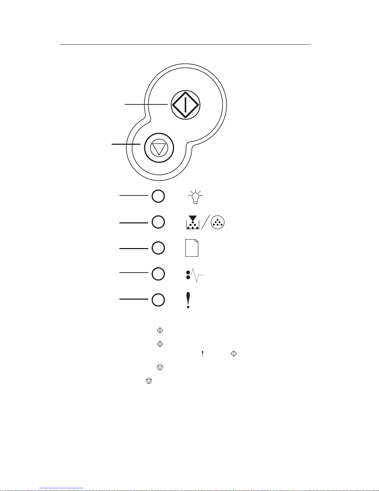
Overview of the operator panel
The operator panel has six lights and two buttons. See
“Operator panel codes” on page 2-8 for more information.
• Press and release to resume printing.
• Press and release twice quickly to display a secondary
error code following an error.
• Press and release to cancel the job currently printing.
• Press and hold until all of the lights come on to reset the
printer.
Continue
Cancel
Ready
Toner Low /
Replace PC Kit
Load Paper
Paper Jam
Error
Page 24

1-4 Service Manual
4505
P aper jams–how to clear
When a paper jam occurs, the printer stops operating and the
operato r panel’s and lights come on. Press and release
twice quickly to display the specific secondary error paper
jam light sequence. See “ Se condary errors” on page 2-6 for
more information.
We recommend the ent ire pape r pat h be cleared whe n a paper
jam occurs.
To clear a paper jam:
1. If the paper is feeding from a tray, remove the tray, and
then rem ove any jam s .
2. Open the fr ont c over an d remove the print cartridge
assembly.
3. R em ove any jam s located in the area behind th e print
cartridge ass embly.
4. Lift the f lap at th e fr on t of t he pri n ter and r emo v e any jam s
located beneath the fla p.
5. Open the rear exit and remove any jams.
6. Afte r you have cleared the jams, reinstall the print cartrid ge
assembly, make sure all printer covers and tra ys are closed, and
then press the button to resume printing.
Note: Pages caught in the paper jam will reprint.
Page 25

General information 1-5
4505
Tips on preventing jams
You can avoid most paper jams by correctly loading paper and
specialty media.
The following hints can help you avoid paper jams:
• Do not load wrinkled, creased, or damp paper.
• Never mix media types within a tray.
• Flex, fan, and straighten paper before you load it.
• Do not exceed the maximum stack height.
• Push all trays firmly into the printer after loading them.
• Make sure the guides in the trays are positioned snugly against
the paper or specialty media.
• Do not remove paper trays while a job is printing. Wait for a
Load Paper light sequence before you remove the tray.
• Before loading transparencies, fan the stack to prevent sheets
from sticking together.
• Do not use envelopes that:
– Have excessive curl
– Are stuck together
– Are damaged in any way
– Contain windows, holes, perforations, cutouts, or embossing
– Use metal clasps, string ties, or metal folding bars
– Have postage stamps attached
– Have any exposed adhesive when the flap is in the sealed
position
• Use only recommended paper. Refer to the Card Stock & Label
Guide available on the Lexmark Web site at www.lexmark.com for
more information about which paper provides optimum results for
current printing environment.
Page 26

1-6 Service Manual
4505
Tools
The removal and adjustment procedures require the following tools
and equipment:
• Magn eti c t ip Phillip s sc r ewdrivers, large and sma ll
• Volt ohmmeter
Page 27

General information 1-7
4505
Types of prin t media
Ensure trays are properly loaded. Never mix media types
within a tray.
Source Sizes Types Weight
Capacity
(sheets)
Tray 1
(250-sheet
tray)
A4, A5,
JIS B5,
lett e r, legal ,
executive,
folio,
statement,
Universal
‡
Plain paper,
transparencies,
labels
60–90 g/m
2
(16–24 lb)
• 250 paper
• labels
• 50 transparencies
Tray 2
(550-sheet
tray)
A4, A5,
JIS B5,
lett e r, legal ,
executive,
folio,
statement,
Universal
‡
Plain paper,
transparencies,
labels
60–163 g/m
2
(16–43 lb)
• 550 paper
• labels
• 50
transparencies
• card stock
Manual
feeder
A4, A5,
JIS B5,
lett e r, legal ,
executive,
folio,
statement,
Universal
‡
Plain paper,
transparencies,
labels , card
stock
†
60–163 g/m
2
(16–43 lb)
1
7¾, 9, 1 0 ,
DL, C5, B5,
other
Envelopes
†
Card stock up to 90# Index. Grain short is recommended.
‡
Universal size range: 76–216 x 127–356 mm (3.0–8.5 x 5.0–
14.0 in.) (includes 3 x 5 in. cards).
Page 28

1-8 Service Manual
4505
Abbreviations
ACM Auto Comp Mechanism (or paper feed)
ASIC Application Specific Integrated Circuit
CBM Complete Bill Of Material
DIMM Dual In-Line Memory Module
ENA Exter nal Network Adapter
FRU Field Replaceable Unit
HBP Host Based Printing
HV High Voltage
HVPS High Voltage Power Supply
INTL International
LVPS Low Voltage Power Supply
NVRAM Nonvolatile Random Access Memory
PCL Printer Control Language
POR Power-On Reset
POST Power-On Self Test
PPDS Personal Printer Data Stream
PRC Peoples' Republic of China
PSO Participating Sta ndards Organizat ion
RIP Raster Image Processor
SDR Synchronou s Dynamic RAM
USB Uni versal Se ria l Bus
V ac Volts alternating current
V dc Volts direct current
Page 29

Diagnostic information 2-1
4505
2. Diagnostic information
Start
POST (power–on self test)
When you turn the printer on, it performs a POST. Check for correct
POST functioning of the base printer by observing the following
process:
1. All operator panel lights flash irregularly for approximately
10 seconds.
2. If there is a problem in the printer such as a paper jam, the
panel lights indicate the problem. See “Common l ight
sequences” on page 2-3 for more information.
3. Otherwi se, the light flashes until the fuser comes up to
temperature (5–20 additional seconds dependin g on the initial
temperature of the fuser).
Note: The operator panel has six lights and two buttons. The
button has a light in it.
Page 30
2-2 Service Manual
4505
Overview of the operator panel
• Press and release to resume printing.
• Press and release twice quickly to display a secondary
error code (following an error -
and lights on).
• Press and release to cancel the job currently printing.
• Press and hold until all of the lights come on to reset the
printer.
Continue
Cancel
Ready
Toner Low /
Replace PC Kit
Load Paper
Paper Jam
Error
Page 31

Diagnostic information 2-3
4505
Understanding the operator panel lights
The operator panel lights mean different things, depending on their
sequence. Lights that are off, on, and/or blinking indicate printer
conditions such as printer status, intervention, or service.
The following tables show the most common light sequences.
Note: See “Primary codes” on page 2-8 for more information.
Common light sequences
See “Overview of the operator panel” on page 2-2 for icon
information.
● Light on
Light is off
✷ Light blinking
x
Light blinking slow
Printer condition
● Ready / Power
Saver
✷ Busy
x
Hex Trace Ready
● ● Waiting
✷✷Flushi ng /
Resolution
reduced
● Not ready (printer
offline)
● Close door /
Insert cartridge
● ● Load media
Page 32

2-4 Service Manual
4505
●
✷ Load manual
feeder
✷●Print side two of
duplex job
● Toner low
●✷ Replace
photoconductor
kit
●✷ ✷Replace
photoconductor
kit (printer hard
stop)
✷●Missing or
defective to ner
cartridge
●●Unsupported
toner cartridge
●✷Change cartridge,
invalid ref ill
●●Invalid en gine
code /
Invalid network
code
●●● Programming
engine code /
Programming
system cod e
● ● ● ●●●Cancel job /
Rese t p rinter
Printer condit ion
Page 33

Diagnostic information 2-5
4505
✷ ✷ ✷ ✷✷✷Service er ror (see
“Service
information with
secondary and
tertiary light
patterns” on
page 2-29 fo r
more in fo rmat ion ) .
✷●Printer error (see
“Secondary
error codes” on
page 2-19 fo r
more in fo rmat ion ) .
Printer condition
Page 34

2-6 Service Manual
4505
Secondary errors
When the and lights are both on, a secondary error has
occurred. Press and release twice quickly to display the
secondary error code light sequence. The following table shows
what these light sequences mean.
Printer
condition
●●Pri nt e r er ro r /
Secondary
error code
● ✷ ● Paper jams in
th e m a nual
feeder
●●●Paper jams as
it exits the tra y
into the printer
●●●Paper jams as
a printed job
exit s the printer
●● ●Complex page
● ✷ ● Insufficient
printer memory
●● ●Insufficient
collation area
● ✷ ● Font error
●●●Defective flash
● ✷ ● Insufficient
defrag memory
●●●Network
interface errors
● ✷ ● Error
communicating
with host
computer
●●● ●Memory full
Page 35

Diagnostic information 2-7
4505
●●●●
Short paper
●●●●Unformatted
flash
●● ●●Flash full
●●●Invalid engine
code
● ✷ ● I nva l i d network
code
Paper jam secondary codes
●● ● 200 Paper jam
input senso r
●●●201 Paper jam
between input
and exit
sensors
●●●202 Paper jam
exit sensor
● ●●● 241 Paper jam
Tray 1 jam
●● ●● 242 Paper Jam
Tray 2 jam
● ✷ ● 251 Paper jam
manual feeder
Printer
condition
Page 36

2-8 Service Manual
4505
Operator panel codes
The following tables explain the primar y light sequences, or codes,
and secondary error codes, what they mean and how to clear them.
Primary codes
Ready / Power Saver
Light sequence Meaning Action:
• Printe r ready to r eceiv e
and process dat a.
• Printer is in Power
Saver mode.
• Send a print job.
• Press to print the
menu settings pages
for a list of current
printer settings.
• Press and hold to
reset the printer.
Note: To change the
Power Saver setting, use
the Local Printe r Setu p
Utility. See Us er’s
Reference for more
information.
Page 37

Diagnostic information 2-9
4505
Busy
Light sequence Meaning Action:
• Printer is busy
receiving and
processi ng data or
printing.
• Printer is
defrag menting the fl ash
memory to reclaim
storage space
occupied by deleted
resources.
• Printer is formatting the
flash memory.
• Printer is storing
resources, such as
fonts or macros, in
flash memory.
• Printer is printing a
directory, font list,
menu setti ngs pages,
or Print Quality Test
Pages.
•Busy:
–Wai t for message to
clear.
–Pr ess and re lease
to cancel print
job.
–Pr ess and hold to
reset printer.
• Defragmenting flash,
formatting flash, or
programmi ng flash:
–Wai t for message to
clear.
–Warning: Do not turn
the printer off while
this message is
displayed.
• Printing a directory, a
font list, menu settings
pages, or Print Quality
Test Pages:
–Wai t for the pages to
print. The Busy
message is displayed
as the pages print.
The light is on
when prin ti ng stop s.
–Pr ess and re lease
to cancel
printing.
–Pr ess and hold to
reset printer.
• Receiving/processing
data from a host
interface:
–Wai t for message to
clear.
–Pr ess and re lease
to stop
processing.
–Pr ess and hold
to reset printer.
Page 38

2-10 Service Manual
4505
Hex Trace Ready
Waiting
Light sequence Meaning Action:
Printer is in the Ready
mode and Hex Trace is
active.
• Hex Trace helps
troubleshoot printing
problems. After
resolving the problem,
turn off the printer to
exit Hex Trace.
• Or, pr ess and hol d
to reset the printer.
Light sequence Meaning Action:
Printer is waiting until a
print timeout occurs, or
until it receives additional
data.
• Press and rel ease
to print content s of the
prin t buffer.
• Press and relea se
to cancel the print job.
• Press and hold to
reset the printer.
Page 39

Diagnostic information 2-11
4505
Flushing / Resolution reduced
Not ready
Light sequence Meaning Action:
• Printer is flushing
corrupted print data.
• Printer is processing
data or printing pages,
but th e resolut ion of a
page in the cur rent
print job is reduced
from 600 dots per inch
(dpi) to 300 dpi to
prevent a memory full
error.
• Wait unt il is
displayed to print other
jobs.
• Press and release
to cancel print job.
• Press and hold to
reset printer.
Light sequence Meaning Action:
Printer is not ready to
receiv e or process data,
or the printer ports are
offline.
• P re s s to return to
or Busy state.
• Press and release
to cancel print job.
• Press and hold to
reset printer.
Page 40

2-12 Service Manual
4505
Close door / Insert cartridge
Load medi a
Light sequence Meaning Action:
The printer door is open. Close the door.
Light sequence Meaning Action:
The printer is out of
media, or the media did
not f eed properly.
• Load media into tray 1
or the optional
550-sheet tray and
press to resume
printing.
• Check tha t the media i s
loaded correctly in
tray 1 or the optional
550-sheet tray.
• Press to cancel
the print job.
Page 41

Diagnostic information 2-13
4505
Load manual feeder
Print sid e t wo of duplex job
Light sequence Meaning Action:
Printer prompts to load a
single sheet of media in
the manual feeder.
• Load media, with the
side to be printed
facing the front of the
printer, into the manual
feeder.
•Press to resume
printing.
• Press and hold to
reset printer.
Light sequence Meaning Action:
Print the other side of
duplex print job.
• Reinsert print job in
tray 1 using the
instructi ons in the
drive r pop-up menu to
orient the pages
correctly.
•Press to resume
printing.
• Press and hold to
reset printer.
Page 42

2-14 Service Manual
4505
Toner low
Replace photoconductor kit
Light sequence Meaning Action:
• Printer is ready to
receiv e and process
data.
• The toner in the toner
cartridge is getting lo w.
• Send a print job.
• Press to prin t the
menu setti ngs page for
a list of curre nt
settings.
• Remov e the toner
cartridge and shake it
to extend the life of the
cartridge.
• Replace the toner
cartridge.
• Press and hold to
rese t printe r.
Note: The light
may not come on if the
starter toner cartridge is
installed in a base printer
model.
Light sequence Meaning Action:
The photoconductor kit’s
drum is full and needs
replacing.
• Press to resume
printing.
• Replace the
photoconductor kit.
Page 43

Diagnostic information 2-15
4505
Replace photoconducto r kit (printer hard stop)
Toner cartridge err or / Toner c art ridge is not inst alled
Light sequence Meaning Action:
The photoconductor kit’s
drum is full and needs
replacing. No pages print
until the photoc onductor
kit is replaced.
• Replace the
photoconductor kit.
Light sequence Meaning Action:
The toner cartridge is not
installed, or the printer
detects a toner cartridge
error.
• If the toner cartridge is
not insta lled , inst all it.
• If the toner cartridge is
install ed, remo v e it and
install a new toner
cartridge.
Page 44

2-16 Service Manual
4505
Cha nge inv alid toner cartridge
Invalid engine code / Invalid network code
Light sequence Meaning Action:
The toner cartridge being
used is not designed for
this printer.
Install a toner cartridge
compatible to printer.
Light sequence Meaning Action:
The code in an internal
print server has not been
programmed, or the
programmed code is not
valid.
• Download valid
network code to the
internal print s e rver.
• Press twice
quickly to see the
secondary error code.
Page 45

Diagnostic information 2-17
4505
Programming engine cod e / Programming syste m code
Cancel job / Reset printer
Light sequence Meaning Action:
New code is being
programmed into the
engine or firmware cod e
flash.
Wait for the message to
clear . When the printer
has finished p rogramming
the code, it performs a
soft reset.
Light sequence Meaning Action:
• The current print job is
canceled.
• The printer is resetting
to the user default
settings.
–Any active print jobs
are canceled.
–A user default setting
remains in eff ec t until
changed or until
restored to factory
default settings.
Wait for the message to
clear.
Page 46

2-18 Service Manual
4505
Service error
Printer erro r
Light sequence Meaning Action:
The pri n ter has a serv i c e
error and printing has
stopped.
Turn the printer off and
back on.
If the light s are still
bli nking, con tact the p lace
where printer wa s
purchased.
Light sequence Meaning Action:
The printer h as on e of th e
fol lowing errors:
• Memory is full,
insufficient to save
what is in the buffer, or
insufficient to
defragment flash
memory.
• A page is too comple x
to pr in t or is sho rte r
than the set page
margins.
• Resoluti on of a
formatted page is
reduced to 300 dpi.
• A font error occurred.
• Communica ti on wit h
the host computer is
lost.
• Press twice
quickly to see the
secondary error code.
See “Secondary err or
codes” on page 2-19
for more information.
• Press to clear the
secondary message.
Page 47

Diagnostic information 2-19
4505
Secondary error codes
• When the and lights are both on, a secondary error has
occurred. Press and release twice quickly to display the
secondary error code light sequence.
• When the and lights are both on, a paper jam
secondary error has occurred.
Press and release t wice to displa y th e secondary error co de
light sequence.
The following tables show what these light sequences mean and
what to do.
Page 48

2-20 Service Manual
4505
Paper jam in the manual feeder
Paper jams as it exits the tray into the printer
Light sequence Meaning Action:
A paper j am h as occur red
in the manual feeder.
Clear the paper j am.
Light sequence Meaning Action:
A paper j am h as occur red
as the paper is ex iti ng the
paper tr ay and entering
the printer.
Clear the paper j am.
Page 49

Diagnostic information 2-21
4505
Paper jams as a printed job exits the printer
Complex page
Light sequence Meaning Action:
A paper jam has occurred
as the paper is exi ting t he
printer.
Clear the paper jam.
Light sequence Meaning Action:
The page may not prin t
correctly because the
print information on the
page is too complex (that
is, too large for the
printer’s memory).
•Press to clear the
message and continue
processi ng the print job
(some of the print dat a
may be lost).
• To avoid this error in
the future:
–Reduce the
complexity of the
page by reduci ng the
amount of text or
graphics on the page
and deleting
unnecessary
downloaded fonts or
macros.
–Set Page Protect to
on in the Local
Printer Setup Utility.
• Install addi tional print er
memory.
Page 50

2-22 Service Manual
4505
Insufficient printer memory
Insufficient collation area
Light sequence Meaning Action:
The printer does not ha ve
enough memory to save
the data in the buffer.
• Install addi tional
memory.
• Press to continue
printing the job.
• Press to cancel
the print job.
Light sequence Meaning Action:
The printer memory does
not have the free space
necessary to collate the
prin t jo b. This may
happen due to one of
these errors:
• Memory is full.
• A page is too comple x
to pr in t.
• A page is shorter than
the set page margins.
• Memory is insufficient
to save what is in the
buffer.
• Press to clear the
message and continue
printing the job (the job
may not print correctly.)
• Press and release
to cancel the print job.
• Press and hold to
reset the printer.
• To avoid this er r o r in
the future:
–Simpl ify the print job.
Reduce the
complexity of the
page by reducing the
amount of te xt or
graphics on the page
and deleting
unnecessary
downloaded fonts or
macros.
• Install add itional printer
memory.
Page 51

Diagnostic information 2-23
4505
Font error
Defective flash
Light sequence Meaning Action:
The printer has recei ved
a request for a PPDS font
which is not insta ll ed.
• Press and release
to cancel the pri nt j ob.
• Press and hold to
reset the pri n ter.
• Press and release
to clear the message
and contin ue printing.
Light sequence Meaning Action:
The printer detect s
defective flash m em ory.
• Press to clear the
message and continue
printing.
–Downloaded fonts
and macros not
previ ously stored in
flash memory are
deleted.
• In s ta ll fl as h memor y.
Page 52

2-24 Service Manual
4505
Insufficient defrag memory
Network interface errors
Light sequence Meaning Action:
The printer has
insufficient memory to
free unused space in
flash memory.
• Delete fonts, macros,
and other data in RAM.
• Install add itional printer
memory.
Light sequence Meaning Action:
The printer cannot
establ ish communic ation
with the network.
Press to clear the
message and conti nue
printing (t he job may not
print correctly).
Page 53

Diagnostic information 2-25
4505
Error communicating with host computer
Memory full
Light sequence Meaning Action:
The printer has lost the
connection to an external
print server (also called
an external network
adapter or external
network adapter (ENA)).
This light sequence is
displa yed if your printer is
connected to the network,
but it can not det ect the
print server when you turn
on the printer.
• Make sure the cable
connecting the ENA
and the printer i s
securel y attached.
• Turn the printer off and
then on to reset the
printer.
• Press and hold to
reset the pri n ter.
Light sequence Meaning Action:
The printer is proce ssing
data, but the mem ory
used to store pages is ful l.
•Press to clear the
message and continue
printing the job (t he job
ma y not print correctly).
• Press and release
to cancel the pri nt j ob.
• Press and hold to
reset the pri n ter.
• To avoid this error in
the future:
–Simplify th e pr in t jo b.
Reduce the
complexity of the
page by reduci ng the
amount of text or
graphics on the page
and deleting
unnecessary
downloaded fonts or
macros.
• Install addi tional print er
memory.
Page 54

2-26 Service Manual
4505
Short paper
Flash full
Light sequence Meaning Action:
The paper length is too
short to print the
formatted data. This
occurs when the printer
does not know t he med ia
size loaded in the tray, or
there is a prob lem f eeding
the media.
• Make sure the print
media you loaded is
large enough.
• Open the front cover,
clear the paper path
and close the cover to
resume printing.
• Press to clear the
message and continue
printing the job.
• Press to cancel
the print job.
Light sequence Meaning Action:
There is not enough free
space in the flash
memory to store the data
you are trying to
download.
• Delete fonts, macros,
and other data stored
on the flash memory to
free up space .
• Press to clear the
message and continue
printing.
–Downloaded fonts
and macros not
previously stored in
flash memory are
deleted.
• Install fl ash memory
with more storag e
capacity.
• Press and relea se
to cancel the print job.
• Press and hold to
reset the printer.
Page 55

Diagnostic information 2-27
4505
Un fo r matte d flas h
Invalid engine code
Light sequence Meaning Action:
The printer detect s
unformatt ed fl ash
memory.
• Press to clear the
message and continue
printing. The job may
not print correctly.
• Reformat the flash
memory. Refer to the
T ec hnical Ref erence on
Lexmark’s Web site for
more info rmation.
• If the error message
remains, the flash
memory may be
defective and should
be replaced.
Light sequence Meaning Action:
The code in an internal
print server has not bee n
pr og ramm e d , or the
programmed code is not
valid.
Download valid engine
code to the internal print
server.
Page 56

2-28 Service Manual
4505
Invalid network co de
Light sequence Meaning Action:
The code in an internal
print server has not been
programmed, or the
programmed code is not
valid.
Download valid network
code to the internal print
server.
Page 57

Diagnostic information 2-29
4505
Service information with secondary and tertiary
ligh t pa tte r ns
All service errors are indicated by all lights flashing as the primary
notification or code. The secondary code indicates an area or
function which has the error. Ter t iar y co des (shown on the following
pages) indicate specific device errors. Double click to see the
secondar y code. Double click again to see the ter tiary code.
Note: All lights flashing simultaneously, as a result of sending data
to the printer, may indicate a code problem. Call the next level of
support.
● Light on
Light off
✷
Light blinking
x
Light blinking slow
Double
Click
Double
Click
Double
Click
D
o
u
b
l
e
C
l
i
c
k
Primary
Codes
Secondary
Codes
Tertiary
Codes
Page 58

2-30 Service Manual
4505
Secondary error codes
Secondary codes
Lights
Primary
code
90x
91x
92x
93x
94x
95x
96x
97x
98x
99x
Continue
✷ ✷✷✷✷✷✷✷✷✷✷
Ready
✷
T oner Low
/
Replace
PC Kit
✷✷✷
Load
Paper
✷✷✷✷✷
Paper Jam
✷✷✷✷✷
Error
✷ ✷✷✷✷✷
Software
DC motor or tra nsfer roll
Fuser or toner sensor
Printhead, drive motor, RIP to engi ne
RIP to engine communication, engine
electronics
Controller card, spec if ically, NVRAM, ROM or
NAND
RAM memory
Network
Paper port communications
De vice system car d
Page 59

Diagnostic information 2-31
4505
Tertiary service error codes
Service error codes are generally non-recoverable except in an
intermittent condition when you can POR (power-on reset) the
printer to temporarily recover from the error.
Note: All se rvice er ro rs a r e in it ially com municated by a ll lights
flashing which is the primary indi cation or code. For brevity, this
indication is not repeated in the following codes.
1. Controller software error/illegal trap (90x)
Call the next level of suppor t for a 900 error.
For the other errors, which indicate a faulty programming
process or faulty component on the controller card, replace the
controller card.
Page 60

2-32 Service Manual
4505
Controller software
Tertiary codes
Lights
900
901
902
903
904
905
906
Continue
✷
Ready
✷✷✷✷✷✷✷
Toner Low /
Replace PC
Kit
Load Paper
✷✷✷
Paper Jam
✷✷ ✷
Error
✷✷✷
RIP
interface
driver
error
General engi ne
softwar e error
Faulty engine code flash or
programming failed
Contact next level of support or
1-800-539-6275
Secondary code
Page 61

Diagnostic information 2-33
4505
Transfer roll
CAUTION: When you see this symbol, there is a
danger from hazardous voltage in the area of the
product where you are working. Unplug the product
before you begin, or use caution if the product must
receive power in order to perform the task.
Code 917 indicates a problem in the transfer roll circuit. Check the
continuity from the cable connection on the HVPS (high volt a ge
power supply) to the right side of the transfer roll.
Tertiary code
Lights
917
Continue
✷
Ready
✷
Toner Low /
Replace PC
Kit
Load Paper
✷
Paper Jam
✷
Error
✷✷
Secondary code
Page 62

2-34 Service Manual
4505
Fuser, fan, or toner sensor error
Codes 920 through 929 indicate a problem in the fuser (see “Fuser
service check” on page 2-53 f or more inf ormation), a stalled fan motor
or a faulty toner sensor or toner cartridge.
Tertia ry c od e s
Lights
920
921
922
923
924
925
926
927
928
929
Continue
✷
Ready
✷✷✷✷✷✷✷✷✷✷
Toner Low /
Replace PC
Kit
✷✷
Load Paper
✷✷✷✷
Paper Jam
✷✷✷✷✷
Error
✷✷✷✷✷
Toner sensor or
toner cartridge
Fuser below
temperatu re when
printing
Incorrect fuser lamp
installed
Open circui t i n
thermistor path
Fuser too hot during
printing or idle
Fuser failed to reach standby te mp erature
Fuser below standby
temperature at idle
Secondary
code
Fan stalled
Page 63

Diagnostic information 2-35
4505
Printhead, transport m oto r or RIP/engine communicatio n error
Codes 930 through 935 indicate a problem with the printhead.
Check cables to the printhead. Replace the printhead as necessary.
Codes 936 and 937 indicate a problem in the drive syst e m.
Page 64

2-36 Service Manual
4505
Code 939 indicates a communication failure between the RIP and
engine processors.
T ertiary codes
Code
930
931
932
933
934
935
936
937
939
Continue
✷
Ready
✷✷✷✷✷✷✷✷✷
Toner Low /
Replace PC
Kit
✷
Load Paper
✷✷✷✷
Paper Jam
✷✷✷✷✷
Error
✷ ✷✷✷✷✷
Secondary
code
Mirror motor not at opening speed.
(Verify +24 V dc on pin #5 of J11.)
Mirror motor lost lock
Printhead - lost hsync
Printhead - no first hsync.
(Verify interlock switch is
plugged in at J13.)
Transport
mot or l o st
lock
Mirror motor locked
Wrong printhe ad
RIP/engine
communication error
Transport
motor in it ia l
lock failure
Mirror motor not at opening speed.
(Verify +24 V dc on pin #5 of J11.)
Page 65

Diagnostic information 2-37
4505
RIP to engine communic a tion failure (co ntroller card).
This indicates fuser control in the LVPS has failed or the wrong LVPS
has been installed.
Tertiary
codes
Code
940
Continue
✷
Ready
✷
Toner Low /
Replace PC
Kit
Load Paper
✷
Paper Jam
Error
Secondary
code
Page 66

2-38 Service Manual
4505
NVRAM failure
Error codes 950–954 indicate a problem in the NVRAM (nonvolatile
random access memory). Replace the operator panel assembly.
Codes 955–959 indicate a failed controller card assembly. Replace
the controller card.
Page 67

Diagnostic information 2-39
4505
Tertiary codes
Code
950
951
952
954
955
956
957
958
959
Continue
✷
Ready
✷✷✷✷✷✷✷✷✷
Toner Low /
Replace PC
Kit
✷✷
Load Paper
✷✷✷✷✷
Paper Jam
✷✷✷
Error
✷✷ ✷✷✷
Secondary code
NVRAM data does not
match secu re NV R AM
RIP firmwar e cann o t
communica te w ith secure
NVRAM
NVRAM chip failu r e
NVRAM CRC failure
SRAM
failure
NAND
failure
ASIC failure
Processor failure
Code ROM or NAND
failed cyclic redundancy
check (CRC)
Page 68

2-40 Service Manual
4505
Note: NVRAM is on the operator panel printed circuit board (PCB)
while secure NVRAM is on the controller PCB. Check margin
alignments after replacing the operator panel assembly. See
“Printhead service check” on page 2-61 for more information. If
margin errors are unacceptable, corrections can only be made
through software. Contact the next level of support or Lexmark at
1-800-539-6275.
Page 69

Diagnostic information 2-41
4505
RAM memory error
This error indicates RAM failure. Remove DIMM(s) and POR the
printer. If the error persists, replace the card. If the error subsides,
check each DIMM independently. Replace faulty DIMM.
T ertiary codes
Code
960
961
962
963
Continue
✷
Ready
✷✷✷✷
Toner Low /
Replace PC
Kit
Load Paper
✷
Paper Jam
✷✷✷
Error
✷✷
Secondary
code
RAM in slot 1 is bad
RAM soldered on the board is bad
Page 70

2-42 Service Manual
4505
Network error
Indicates an error in the network circuitry . Replace the controller
card assembly.
T ertiary codes
Code
970
971
972
973
974
975
976
978
979
Continue
✷
Ready
✷✷✷✷✷✷✷✷✷
Toner Low /
Replace PC
Kit
✷✷
Load Paper
✷✷✷✷
Paper Jam
✷✷✷✷
Error
✷ ✷✷✷ ✷
Unrecognizable
network port
Unrecoverable software error in network port
Bad checksum wh il e programmi ng port
Flash parts failed while progr am ming port
Secondary code
Page 71

Diagnostic information 2-43
4505
Paper po rt communicati on fai lure
Indicates an error communicating with Tray 2, if installed. Remove
Tray 2 and recheck. If the error does not recur, replace Tray 2. If the
error recurs, replace the controller card assembly
T ertiary codes
Code
980
981
982
983
984
Continue
✷
Ready
✷✷✷✷✷
Toner Low /
Replace PC
Kit
✷
Load Paper
✷
Paper Jam
✷✷
Error
✷✷
Secondary code
Engine experiencing
unrel iable comm unicatio ns
to specified device
Engine protocol violation detected by
the spec ified devi ce
Communi cations er ror detecte d by
specified device
Invalid command
received by specified
device
Invalid command
parameter
received by
specified device
Page 72

2-44 Service Manual
4505
Symp to m tabl es
POST symptom table
Symptom Action
The main motor, cooling fan,
and fuser do not come on.
See “Cover in terlock sw itch service
check” on page 2-51.
POST completes except one or
more lights do not come on.
See “Operator panel service ch eck”
on page 2-59.
None of the lights co me on. See “Operator pane l service chec k”
on page 2-59.
Main motor does not come on. See “Main motor service check” on
page 2-58.
Fan does not come on. See “Cooling fan service check” on
page 2-48.
Fuser lamp does not come on. See “Cold fuser service check” on
page 2-47.
Fuser lamp never turns off. See “Hot fuser servi ce check” on
page 2-56.
The paper feed picks and tries
to feed paper.
See “Paper feed service checks” on
page 2-61.
Page 73

Diagnostic information 2-45
4505
Printer symptom table
Symptom Action
Dead machine (no po wer) See “Dead machine service check”
on page 2-52.
Fan noisy or not working See “Cooling fan service che ck” on
page 2-48.
Fuser parts melted See “Hot fuser service check” on
page 2-56.
Fuser lamp doesn’t light See “Cold fuser service check” on
page 2-47.
Toner not fused to the paper See“Cold fu ser service check” on
page 2-47.
Paper jams See “Pap er feed service checks” on
page 2-61.
Main motor noi sy or not moving See “Main motor service check” on
page 2-58.
Paper skew See “Pap er feed service checks” on
page 2-61.
Printer not communicating with
host
See “Parallel port service check” on
page 2-65.
Front access cover will not
close
See “Cover interlock switch service
check” on page 2-51.
Operator panel button not
responding
See “Operator panel service check”
on page 2-59 or “Co n tro ller ca rd
service check” on page 2-49.
Operator panel lights are off or
very dim
See “Contr oller card service chec k”
on page 2-49.
Blank page See “Blank page” on page 2-67.
Black page See “Black page” on page 2-68.
Heavy backgrou nd See “Heavy bac kground” on
page 2-69.
Light print See “Light print” on page 2-71.
Page 74

2-46 Service Manual
4505
White or black lines or bands See “White or black lines or bands”
on page 2-72.
Toner on back of page See “Toner on back of page” on
page 2-72.
Paper never picks See “Paper never picks” on
page 2-63.
Paper feeds continuously See “P aper pic ks during POST and/or
continuously” on page 2-62.
Paper wri nkled or bent See “Paper “trees,” wrinkles, stacks
poorly or curls” on page 2-65.
Symptom Action
Page 75

Diagnostic information 2-47
4505
Ser vi ce checks
Service checks which involve measuring voltages on
the LVPS/HVPS (
low voltage power sup ply/high voltage
pow er supply
board) should be performed with the printer
positioned on its back side.
Note: When you make voltage readings, always use frame ground
unless another ground is specified. See “Wiring di agram ” on
page 5-4 for m ore information.
Cold fuser service check
Make sure the cor rect voltage lamp is install ed. The voltage rating is
stamped on one of the lamp con tacts.
FRU Action
Fuser AC cables
LVPS/HVPS
Fuser
If the fuser l am p com es on and a
fuser f ailure light error code displ ays ,
be sure the thermistor is contacting
the hot roll and the thermistor cable
is firmly seated in connector J15 on
the contr oll er card.
Check for excessi ve t one r b uildup on
the surface of the thermist or. Clean
as necessary.
With the printer unplugged,
disconnec t the th ermistor ca ble f rom
J15 on the contr oller card.
Measure the res istance of the
thermistor . The resistanc e measures
from approximately 1K ohms
immediate ly after printing or POR to
approximately 240K ohms when
thermistor reaches room
temperat ure. (It may take 30 minu tes
to cool.)
Replace the fuser assembly as
necessary.
Page 76

2-48 Service Manual
4505
Cooling fan service check
FRU Action
Cooling fan Make sure the fan cable plug is
properly seated at J19 (controller
card).
Turn the printer off and disconnect
the cooling fan cable from the
controller card.
Turn the printer on. Within a few
seconds the cont roller card
assembly should apply between
+24 V dc to pin 2. See “Controller
board” on page 5-3 for more
information.
• If voltage is present and the fan is
not turning, replace the cooling
fan. If the fan st i ll doesn ’t functi on,
replace the controller card.
Note: The f an speed is cont rolled b y
a module on the PCB.
Between +8 V and +24 V dc
are consta ntly supplied at
pin 2 (J19). Pin 1 is ground
while pin 3 receives f ee dback
from the fan motor.
• If voltage is not present, see
“Controller board” on page 5-3
for more information.
Page 77

Diagnostic information 2-49
4505
Controller card service check
FRU Action
Controller card assembly Verify +24 V dc input from the
LVPS/HVPS.
• Turn the printer off.
• Disconnect the LVPS/HVPS
cable from the controller card at
J7. See “Controller board” on
page 5-3 for more information.
• Turn the printer on.
V e rify +24 V dc from the cable
connector of J9, pin 8.
Verify that pin 7 on both the cable
and the card connectors is ground.
• If volt age is correct, check the
continuity in the cable. If the
cable is good, see the
“Controller board” on
page 5-3 for more information.
• If grounds are not correct on the
cable, first check it for continuity
and then the LVPS/HVPS.
• If the grounds are not correct on
the contr oller card, replace the
controller card. (Check with one
probe on the connector pin and
the other on the card’s ground
plane found at each screw
head.)
Page 78

2-50 Service Manual
4505
Controller card service check (continued)
FRU Action
Controller card assembly Note: With all cable s conn ected, the
printer should complete
POST within approximatel y
12–15 seconds in the
fol lowing sequence:
1. All operator panel lights on solid
momentarily.
2. Lights then flash on and off
sequentially.
After lights quit flashing, the
light turns on solid.
3. The cooling fan come s on.
4. The fuser lamp comes on.
5. The drive motor runs.
6. The printhead motor runs.
7. The printer cycles do wn into
standby mode/ready.
If immediately following power–on
the operat or panel lights are act ive
but the printer does not go through
steps 1 and 2 above, replace the
control ler card assembly.
Note: Settings for U.S. versus
non–U.S. and the printer
configuration ID can be
changed. See
“Configuration and
diagnostic groups” on
page 3-1 for more
information.
If some lights are on or flashing,
see “Common light sequences”
on page 2-3 to determine action
required.
Page 79

Diagnostic information 2-51
4505
Cover interlock switch service check
Note: Make sure a print cartr idge assem bly is installed and the
cover closes all the way, engaging the cover open switch
lever.
FRU Action
Cover interlock swit ch Disconnect the cover interlock cable
from the cont rol ler card at J13.
Verify continuit y between cabl e
pin 1 and pin 2 with the door closed
but not open.
Verify continuit y between cabl e
pin 1 and pin 3 with the door open
but not closed.
• If either f ail contin uity, replace the
cover interlock switch.
• If both pass con ti n uity, turn the
printer on and verify +5 V dc on
pin 2 at J6 on the control ler card.
• Verify pins 1 and 3 are ground.
• If vo ltage or gro und is no t pr esent,
see “Controller card service
check” on page 2-49 for more
information.
Verify dis continuity between pins 2
and 3 whether the door is open or
closed.
Replace the co ver interl ock swi tch if
faulty.
Page 80

2-52 Service Manual
4505
Dead machine service check
CAUTION: Check the AC line voltage. The voltage should be
within the following limits:
• 100 V ac (volts alternating current) – 127 V ac for the 110 V
printer
• 200 V ac – 240 V ac for the 220 V printer
FRU Action
LVPS/HVPS
Unplug the printer and check the
fuses on the LVPS/HVPS board for
continuity.
• If open, replace the LVPS/HVPS
board.
–I f fuse opens again, see “LVPS/
HVPS service chec k” on
page 2-57 for more information
• If not open, unplug the cab les at
CN102 and CN201 (fuser and
controller card respectively).
Plug LVPS/HVPS board to source
and turn switch on.
Verify 24 V dc on pin 8 at connector
CN201.
Verify line voltage (110 or 220 V ac)
across pins 1 and 2 of CN102.
• If either voltage is not correct,
replace the LVPS/HVPS board.
• If both vo lt ages are correct, check
the controller card. See
“Controller board” on page 5-3
for more information.
Verify grounds.
Page 81

Diagnostic information 2-53
4505
Fuser service check
When toner is partially fused to the paper, it is usually caused by low
fuser temperature.
Warning: Avoid handling the lamp as much as possible as it is
easily broken. Be careful not to touch the glass housing
with bare hands because skin acids can weaken the
glass. The lamp is not a service part .
The line voltage to the printer must be within the following limits:
• 100 V ac–127 V ac for the 110 V model printer
• 200 V ac–240 V ac for the 220 V model printer
Turn the printer off and wait a few minutes for the fuser lamp to cool.
Turn the printer on and observe the lamp turning on during POST.
You can see the light from the lamp by opening the left
side cover and observing the upper opening through
which the fuser power cables pass.
Page 82

2-54 Service Manual
4505
Fuser service check (continued)
FRU Action
Lamp cable
LVPS/HVPS
Fuser
Unplug the printer and disconnect
the fuser lamp cable plug from the
LVPS/HVPS board connector
CN102.
Check for con tinu it y across th e fuser
lamp by checking across the
connector pi ns.
• If there is continuity, go to Step 1:
Continuity.
• If there is no continuity, go to
Step 2: No continuity.
Step 1: Continuit y
Turn the printer on with only the
fuser power disconnected.
Measure the voltage at connector
CN2 on the LVPS/HVPS. It should
match the line vol tage.
• If line voltage is not present, see
“LVPS/HVPS service check” on
page 2-57 for more inform a tion.
Make sure the fuser thermistor is
correctly connected to the controller
board. If the problem persists,
disconnect the thermistor cable at
J15 and check for less than +5 V dc
on pin 1. Pin 2 should be ground.
• If line voltage i s incor rect on pi n 1,
see “Controller card service
check” on page 2-49 for more
information.
Step 2: No continuit y
Check the lamp cable for continu it y.
• If correct, replace the fuser.
• If incorrect, replace the lamp
cable.
Page 83

Diagnostic information 2-55
4505
Fuser service check (continued)
FRU Action
Fuser (continued)
Disconnec t the thermistor cable fr om
J15 on the contr oller card.
Measure the resistance acr oss the
ends of the the rmist or cable . See
“Connector l ocations” on
page 5-1 for more information.
Replace the fuser assembl y if the
resist ance is lower than 1K ohm or
shorted.
Note: Resistance measures
approximately 240K ohms
when cool and 1.4K ohms
hot.
Page 84

2-56 Service Manual
4505
Hot fuser service check
Note: Ensure correct lamp is installed.
FRU Action
Fuser AC cables
LVPS/HVPS
Fuser
Measure the resistance of the
thermistor . The r esistance meas ures
from approximately 1K ohms
immediately aft er printing or POR to
approximately 240K ohms when
thermistor reaches room
temperatu re. (It ma y tak e 30 min utes
to cool.)
Replace the fuser assembly as
necessary.
Page 85

Diagnostic information 2-57
4505
LVPS/HVPS service check
FRU Action
LVPS/HVPS
LVPS portion of boar d
Fuses that open typically indicate a
faul ty LVPS/HVPS.
Use the voltage meter to verify the
appropriate voltage at t he prin ter
end of the po wer cable.
Remove t he LVPS/HVPS assembly
from the printer.
Check continuity on the fuses.
If either f use has opened, replace
the card.
Ensure the switch is off and plug the
power cord into the card.
Turn the switch on.
CAUTION: The card has several
points where A C voltage is
exposed.
Carefully verify the AC voltage
between pins 1 and 2 matches the
pow er cable (wall) vol tage.
• If voltage is incorre ct, replace the
card assemb ly.
V e rify +24 V dc fro m pin 8 at CN201.
• If voltage is incorre ct, replace the
card assemb ly.
HVPS portion of board
Probl ems wit h the HVPS are
exhibited in the print quality. See
“Print quality service chec ks” on
page 2-66 for more infor mation.
Page 86

2-58 Service Manual
4505
Main motor service check
FRU Action
Main motor cable
LVPS/HVPS
Controller card
Warning: Do not replace
the operator panel and
controller card at the same
time. Each card conta ins
the p r inter sett in gs. Wh en
either of these cards is
new, it obtains the settings
from the other card.
Settings are lost when both
are new and replaced at
the same time.
Verify +24 V dc at J9, pin 8 and
+5 V dc at pin 1 (controller card).
V eri fy gr ound at pins 2 and 7 f or bo th
the card and cable.
• If these voltages are correct,
check the main motor cable for
continuity.
–Remove rear cover to access
connector on motor.
–I f cont inuity exists on each wire,
call next level of servic e.
–I f cont inuity does not exist on
one or more of the wires ,
replace the motor cable.
• If these voltages are not correct,
see the “LVPS/HVPS service
check” on page 2-57 or replace
the controller card.
Note: The main motor is not a
service part.
Page 87

Diagnostic information 2-59
4505
Operator panel service check
Inspect the operator panel cable for damage. Mak e sure the cabl e i s
plugged in securely.
Run POST and check each light for proper operation.
Operator panel service check
FRU Action
Operator panel Buttons
Open control ler card cage and
locate the operator panel connector
at J16.
Check for continuity betw een pins 1
and 2 of the cabl e as you press the
Continue button.
Similarly, check the continuity
between pins 1 and 6 of the cable
while pressing Cancel .
• If cont inui ty i s not presen t, repl ace
the operat or panel.
Note: Check margin alignments
after replacing the operator
panel assembly. If margin
errors are unacceptable,
corrections can only be made
through sof tware. Contact the
next level of support or
Lexm ark at
1–800–539–6275.
Page 88

2-60 Service Manual
4505
Operator panel service check (continued)
FRU Action
Operator panel
Controller card
Warning: Do not replace the
operator panel and
controller card at the
same time . Each card
contains the printer
settings. When either
of these cards is new,
it obtains the settings
from the other card.
Settings are los t when
both are new and
replaced at the same
time.
Lights
If none of the ligh ts come on, make
sure the cable is properly connected
to the controller card and the
controller c ard has input v olt age t o i t.
Verify +24 V dc on cable pin 8 at J7.
• Check for +5 V dc at J16, pin 5
See “Controller card service
check” on page 2-49 or page 5-3
for more information.
• If these voltages are not correct,
replace the controller card.
• If these voltages are correct,
replace the operator panel.
If more than one light does not turn
on or an individual li ght sta ys on
solid during POST, replace the
operator panel.
If all lights ar e dim and operate
erratically during POST or all lights
come on and stay on solid during
POST, replace the FRUs in th e
following orde r one at a time:
• Controller card
• Operator panel
Page 89

Diagnostic information 2-61
4505
Printhead service check
Paper feed service checks
Paper jam error in di ca tio n during POS T
FRU Action
Printhead
Unplug the printer.
Disconnect the printhead cables
from J11 and J12 on the controller
card.
Turn the printer on.
On the c o ntroller card, verify
+24 V dc on pin 5 at J11 and
+5 V dc on pin 7 at J12.
Verify grounds on pin 4 at J11 and
on pins 2, 6, and 8 at J12.
• If voltages or grounds are
incorre ct, check the controller
card. See “Controller card
service check” on page 2-49 for
more information.
• If vo ltages are cor rect, repla ce the
printhead (comes wit h cables).
FRU Action
Exit senso r If the e xit sensor flag is not resting
within the paper exit sensor during
POST, the printer displays a paper
jam message. Make sure the flag is
operating freely and is correctly
installed.
Input sens or
Input sens or #1 (under print
cartridge assembly) and
Input sens or #2 (manual)
Make sure the input paper feed
sensors ar e w orki ng properly. A
stuck or incorrectly installed sensor
causes this error.
Page 90

2-62 Service Manual
4505
Paper picks during POST an d/ or continuou s ly
Paper picks but stops half way through the printer
FRU Action
ACM (auto com p me chanism or
paper feed) clutch
Manual feed clutch
Check the ACM clutch for wear. The
solenoid interacts with the clutch to
control the motion of the pick tires.
If the rat che t te eth of the AC M cl utc h
assemb ly ar e worn or broken, the
solenoid ma y not stop the A CM from
rotating. Replace the ACM clutch
assemb ly i f necessary.
Check the man ual fee d clutc h for th e
same damage.
FRU Action
Input sensor #1 (under print
cartridge assembly) and
Input sensor #2 (manual)
Make sure the i nput sensors are
working properly.
Check for a broken or st uck flag on
the input sensors.
Make sure the cables are seated on
the controller card at J20 (Tray 1
input) and J18 (manual input).
Check for less than +5 V dc on pin 3
at J20 (Tray 1 input) and pin 1 at J 18
(manual inp ut sensor).
• If correct, replace the input paper
feed sensor.
• If these voltages are not correct,
replace the controller card.
Page 91

Diagnostic information 2-63
4505
Paper never picks
FRU Action
Paper fee d (pick tire s) Open the left cover and verif y the
solenoid and clutch are functioning
when an attempt is made to f eed the
paper.
Make sure the rubber tires are
installed and clean.
Replace if necessary.
Page 92

2-64 Service Manual
4505
Paper occasionally picks or picks multiple sheets at once
FRU Action
Tray 1
Tray 2 (opti on)
Check tr ay fo r paper catch points.
If the sheet being fed stops
momentarily, the ACM applies
additional vertical force causing
additional sheets to feed.
Do not mix paper types.
Paper pic k tires Check t he t ires in the A CM assem bl y
for si gns of wear or damage .
Replace the tires as necessary.
ACM clutch complete bill of
materia l (CBM)
Manual feed clutch CBM
Open left co ver and observ e the
solenoid and clutch actions at the
ACM and manual feed shaf ts as a
print job is attempted.
Replace the faulty part.
Controller card Disconnect the solenoid cable at J5
on the controller card.
Measure the res istance acr oss cabl e
pins 1 and 2 and then pins 3 and 4.
• The resistance should be
180–210 ohms.
• If it is not, call the next level of
service.
• If the resist ance is 180– 210 ohms,
check the cont roller card. See
“Controller card service check”
on page 2-49 for more
information.
Replace controller card as
necessary.
Page 93

Diagnostic information 2-65
4505
Paper “trees,” wrinkles, stacks poorly or curls
Parallel port service check
1. Perform a print test to make sure the printer p rints co r re ctly.
Verify is on, press to print menu settings.
2. Be sure the printer cable is designed for bidirectional printing.
3. Be sure the user Program is set up correctly.
4. If the interna l print test page prin ts correctly, the user
Program/printer driver is set up correctly and the correct
bidirectional parallel cable is installed, but the printer still fails to
print on command from the host computer, replace the
controller card.
FRU Action
Fuser This problem is most likely due to a
worn backup roll. It causes the
printer to run hotte r than required for
the media being printed. Excessive
heat can cause paper treeing
problems, poor stacking, or curl.
Page 94

2-66 Service Manual
4505
Print qua lity service c hecks
Note: Ensure cover is closed tightly . A gap in the opening may allow
light to expose the photoconductor resulting in a ‘dirt y’ prin t.
Using pr int qu ali ty test pages
To help isolate print quality problems, like streaking, print test pages
using the print quality test pages setting:
1. Turn the printer on with pressed and the front door open.
2. When
light stays on, close cover.
3. Wait (approximately 7 seconds) until the printer drive activates.
4. Enter the configuration menu. See “Configuration and
diagnostic groups” on page 3-1 for more information.
5. Slowly press and release three times until the and
lights come on.
6. Press and hold until all the lights flash to initiate print quality
test pages.
Three pages print to help you evaluate print quality. The first
page has various fonts, the second page is gray, and the third
page is black. Once the paper exits into the output bin, the
printer return s to the home state (four top lights on).
7. U se the test pages to isolate problems such as light or toner
streaks. See “Symptom tables” on page 2-44 for solutions to
these problems.
8. To exit print quality test pages, turn the printer off.
Page 95

Diagnostic information 2-67
4505
Blank page
FRU Action
Toner cartridge (not a FRU) Remove the toner cartridge and
gently sha ke it to evenly distribute
the toner.
Check for cartridge damage .
Printhead
LVPS/HVPS
Controller card
Toner electrode s (cable
assembly)
Blank pages can be caused by a
defective printhead assembly,
LVPS/HVPS, or controller card.
• Printhead errors typically result in
printer service errors.
• Blank pages typically are caused
by the PC roll not being properly
charged. Try a differe nt PC kit.
Unplug the printer and check
continuity between the LVPS/HVPS
connection pads marked OPC and
the corre sponding pin insi de the
printer.
• If there is not co ntinuity, call the
next level of service.
Try a different toner cartridge and
PC kit.
• If those fail, replace the
LVPS/HVPS.
Page 96

2-68 Service Manual
4505
Black page
Note: Incorrect laser exposure or incorrect charging of the
photoconductor causes an all black page. Always verify the
same results from a different print cartridge assembly and
developer before proceeding.
FRU Action
Toner electrodes (not a FRU) Check t he electrodes below the print
cartridge assembly for
contaminat ion or damage. Correct
as necessary.
Check continuity between the cable
connections on the contact t ips
below the print cartridge assembly.
• If continuity fails, call the next level
of service.
LVPS/HVPS board
Controller card
With the printer off, disconnect the
LVPS/HVPS cable from J7 on the
controller card.
Turn the printer on and verify
+24 V dc on pin 8 of the cable.
Verify ground on pin 7.
• If the voltage is incorrect, replace
LVPS/HVPS board.
• If voltage is correct and the toner
electrodes are good, replace the
controller card.
Page 97

Diagnostic information 2-69
4505
Heavy ba ckgrou nd
Poor de vel opment or poorly charged toner particles cause excessive
background. This is more noticeable as the toner cartridge nears
end–of–life.
FRU Action
Toner cartridge (not a FRU)
PC Kit (not a FRU)
Make sure the toner cartridge and
PC Kit are correc tly in stalled and the
high voltage contac ts are clean.
If the toner cartridge and PC Kit are
installed correctly, try a new PC Kit
first and then toner cartridge.
LVPS/HVPS
Controller card
Check the contacts for correct
install ation and contami nation where
contact is made between the print
cartridge assembly, and L VPS/HVPS
board. Clean as necessary.
If this does not correct the problem,
replace the following FRUs one at a
tim e in the orde r sh own:
• LVPS/HVPS board
• Controller card
Page 98

2-70 Service Manual
4505
Pa rtial blank image/ w hite spots (no peri od ic pat te rn)
Variation in image density horizo ntally across page
FRU Action
Toner cartridge (not a FRU) Remov e the t oner cartridge
assemb ly and gently shake the
assemb ly t o evenl y distribut e the
toner.
If toner cartridge is low, try a new
one.
Paper (not a FRU) Make sure recommended paper is
being used.
FRU Action
PC Kit (not a FRU) The charge roll may have an
unbalanced pr essure against the
Photoconductor (PC) drum.
Try a new PC Kit.
Transfer roll Check the springs in the left and
right transfer roll beari ngs. The
bearing assemblies shoul d support
the trans fer roll, applying even
pressure to the PC drum.
Replace the transfe r roll assembl y if
the springs o r bearing show signs of
damage or fatigue.
Inspect th e tr ansfer roll for signs of
wear, damage or contamination.
Replace as necessary.
Page 99

Diagnostic information 2-71
4505
Poor fusing of ima ge
Light print
FRU Action
Fuser The fuser may not be operating at
the proper temperature to fuse the
toner to the paper. See“Hot fuser
service check” on page 2-56 for
more in formation .
Paper (not a FRU) Make sure re com m ended paper is
being used.
FRU Action
Toner cartridge (not a FRU) Make sure the toner cartridge and
PC Kit are installed correctly and
that the toner cartridge is not low on
toner.
If the problem continues, instal l a
new toner cartridge.
Recheck condition before replacing
PC Kit, if necessary.
Transfer roll
LVPS/HVPS board
Check the t ransf er roll f or si gns of
toner buildup and contamination.
Inspect the HVPS contact (transfer
roll) for contamination.
Verify the high volt age cable is
plugged into th e LVPS/HVPS.
If all components appear free of
contamination, replace the following
FRUs one at a time in the order
shown:
• Transfer ro ll
• LVPS/HVPS board
Page 100

2-72 Service Manual
4505
White or bl ack lines or bands
Toner on back of pag e
FRU Action
Print cartridge assembly ( not a
FRU)
Developer drive coupling
assembly
Banding appears as light or dark
horizontal lines on a uniformly gray
page or on a page with a large area
of graphics. Banding is primarily d ue
to a variation in the speed of the
paper as it feeds through the pri nter
especial ly i n the developer and
transfer process.
Inspect the toner cartridge and
paper feed components, especiall y
the drive coupler and drive gears for
debris, binds or damage.
FRU Action
PC Kit (not a FRU) Inspect the overall paper path for
signs of spill ed toner .
Gently cl ean the contami nated areas
with a soft clot h or compressed air.
Fuser The fuser hot roll can cause toner
deposits on the back of the paper if
toner is buil ding up on the hot roll.
This buildup may transfer to the
backup roll, later transf erri ng to the
back of the paper.
Inspect the hot roll and backup roller
for si gns of contaminati on.
Replace the fuser as necessary.
Transfer r oll A transfe r rol l contaminated with
toner can cause toner to transfer to
the back of print ed pages.
Inspect the transfer roll for
contamination and replace as
necessary.
 Loading...