

Page 1

Lexmark E210
• Table of Contents
• Start Diagnostics
• Safety and Notices
• Trademarks
4510-001
•Index
• Manuals Menu
Lexmark and Lexmark with diamond
design are trademarks of Lexmark
International, Inc., registered in the
United States and/or other countries.
Page 2

4510-001
Edition: June 2001
The following paragraph does not apply to any country where such provisions are
inconsiste nt with local law: LEXMARK INTERNATIONAL, INC. PROV IDES THIS
PUBLICATION “AS IS” WITHOUT WARRANTY OF ANY KIND, EITHER EXPRE SS OR
IMPLIED , INCLUDING, BUT NOT LIMITED TO, THE IMPLIED WARRANTIES OF
MERCHANTABILITY OR FITNESS FOR A PARTICULAR PURPOSE. Some states do
not allow disclaimer of express or implied warranties in certain transactions; therefore, this
statement may not apply to you.
This publication could include technical inaccuracies or typographical errors. Changes are
periodically made to the information herein; these changes will be incorporated in later
editions. Improvements or changes in the products or the programs described may be
made at any time.
Comments may be addressed to Lexmark International, Inc., Department D22A/032-2,
740 West New Circle Road, Lexington, Kentucky 40550, U.S.A or e-mail at
ServiceInfoAndTraining@Lexmark.com. Lexmark may use or distribute any of the
information you supply in any way it believes appropriate without incurring any obligation
to you. You can purchase additional copies of publications related to this product by
calling 1-800-553-9727. In other countries, contact your point of purchase.
Lexmark and Lexmark with diamond design are trademarks of Lexmark International,
Inc., registered in the United States and/or other countries.
Other trademarks are the property of their respective owners.
© Copyright Lexmark International, Inc. 2001.
All rights reserved.
UNITED STA TES GOVERNMENT RESTRICTED RIGHTS
This software and documentation are provided with RESTRICTED RIGHTS. Use,
duplication or disclosure by the Government is subject to restrictions as set forth in
subparagraph (c)(1)(ii) of the Rights in Technical Data and Computer Software clause at
DF ARS 252.227-7013 and in applicable FAR provisions: Lexmark International, Inc.,
Lexington, KY 40550.
P/N 12G6119
Page 3

4510-001
Table of Contents
Laser Notices. . . . . . . . . . . . . . . . . . . . . . . . . . . . . . . . . . . . . . . . . . . .v
Safety Information. . . . . . . . . . . . . . . . . . . . . . . . . . . . . . . . . . . . . . xiii
Preface . . . . . . . . . . . . . . . . . . . . . . . . . . . . . . . . . . . . . . . . . . . . . . xviii
General Information . . . . . . . . . . . . . . . . . . . . . . . . . . . . . . . . . . . . 1-1
Printer Side View - Locations . . . . . . . . . . . . . . . . . . . . . . . . . . . 1-1
Maintenance Approach . . . . . . . . . . . . . . . . . . . . . . . . . . . . . . . . 1-2
Tools Required for Service . . . . . . . . . . . . . . . . . . . . . . . . . . . 1-2
Abbreviations . . . . . . . . . . . . . . . . . . . . . . . . . . . . . . . . . . . . . . . 1-2
Diagnostic Aids . . . . . . . . . . . . . . . . . . . . . . . . . . . . . . . . . . . . . . . 2-1
Print Quality . . . . . . . . . . . . . . . . . . . . . . . . . . . . . . . . . . . . . . . . . 2-1
Vertical Black Line and Band . . . . . . . . . . . . . . . . . . . . . . . . . 2-1
Vertical White Line . . . . . . . . . . . . . . . . . . . . . . . . . . . . . . . . . 2-1
Horizontal Black Band. . . . . . . . . . . . . . . . . . . . . . . . . . . . . . . 2-1
Black/White Spots. . . . . . . . . . . . . . . . . . . . . . . . . . . . . . . . . . 2-2
Light Image . . . . . . . . . . . . . . . . . . . . . . . . . . . . . . . . . . . . . . . 2-2
Dark or Black Image . . . . . . . . . . . . . . . . . . . . . . . . . . . . . . . . 2-2
Uneven Density. . . . . . . . . . . . . . . . . . . . . . . . . . . . . . . . . . . . 2-3
Background. . . . . . . . . . . . . . . . . . . . . . . . . . . . . . . . . . . . . . . 2-3
Residual Image at 75 mm Intervals (1) . . . . . . . . . . . . . . . . . . 2-3
Residual Image at 75 mm Intervals (2) . . . . . . . . . . . . . . . . . . 2-4
Residual Image at 32 mm Intervals. . . . . . . . . . . . . . . . . . . . . 2-4
Residual Image at 57 mm Intervals. . . . . . . . . . . . . . . . . . . . . 2-4
Toner on Front of Page. . . . . . . . . . . . . . . . . . . . . . . . . . . . . . 2-5
Toner on Back of Page . . . . . . . . . . . . . . . . . . . . . . . . . . . . . . 2-5
Blank Page Printout (1). . . . . . . . . . . . . . . . . . . . . . . . . . . . . . 2-5
Blank Page Printout (2). . . . . . . . . . . . . . . . . . . . . . . . . . . . . . 2-6
Repeated marks or voids down page . . . . . . . . . . . . . . . . . . . 2-6
Paper Feed . . . . . . . . . . . . . . . . . . . . . . . . . . . . . . . . . . . . . . . . . 2-7
Printing in wrong position . . . . . . . . . . . . . . . . . . . . . . . . . . . . 2-7
Paper stopping, jamming, or feeding multiple sheets . . . . . . . 2-7
Paper Path Jam 0 . . . . . . . . . . . . . . . . . . . . . . . . . . . . . . . . . . 2-9
Paper Path Jam 1 . . . . . . . . . . . . . . . . . . . . . . . . . . . . . . . . . . 2-9
Paper Path Jam 2 . . . . . . . . . . . . . . . . . . . . . . . . . . . . . . . . . 2-10
Service . . . . . . . . . . . . . . . . . . . . . . . . . . . . . . . . . . . . . . . . . . . 2-10
All LEDs blinking (Printhead Error) during a print job . . . . . . 2-10
All LEDs blinking (Fuser Error) at power up . . . . . . . . . . . . . 2-11
The LED blinks once then all other LEDs blink (Over Heat Error)
iii
Page 4

4510-001
2-11
The LED blinks once then all other LEDs blink (Low Heat Error).
2-12
The LED blinks once then all other LEDs blink (Open Fuser Error)
2-13
False Paper Empty Indication . . . . . . . . . . . . . . . . . . . . . . . .2-13
False Pape r Present Indication . . . . . . . . . . . . . . . . . . . . . . .2-14
False Cover Open Indicator. . . . . . . . . . . . . . . . . . . . . . . . . .2-14
Error LED Off When Cover Open. . . . . . . . . . . . . . . . . . . . . .2-15
Drive Motor Does Not Operate. . . . . . . . . . . . . . . . . . . . . . . .2-15
No Power . . . . . . . . . . . . . . . . . . . . . . . . . . . . . . . . . . . . . . . .2-16
Repair Information . . . . . . . . . . . . . . . . . . . . . . . . . . . . . . . . . . . . . .3-1
Handling ESD-Sensitive Parts . . . . . . . . . . . . . . . . . . . . . . . . . . .3-1
Front Cover . . . . . . . . . . . . . . . . . . . . . . . . . . . . . . . . . . . . . . .3-2
Other Covers . . . . . . . . . . . . . . . . . . . . . . . . . . . . . . . . . . . . . .3-5
Operator Panel. . . . . . . . . . . . . . . . . . . . . . . . . . . . . . . . . . . . .3-6
Printhead . . . . . . . . . . . . . . . . . . . . . . . . . . . . . . . . . . . . . . . . .3-8
Transfer Roller . . . . . . . . . . . . . . . . . . . . . . . . . . . . . . . . . . . .3-10
Motor Assembly . . . . . . . . . . . . . . . . . . . . . . . . . . . . . . . . . . .3-11
Pick Roller Clutch Solenoid . . . . . . . . . . . . . . . . . . . . . . . . . .3-11
HVPS Board. . . . . . . . . . . . . . . . . . . . . . . . . . . . . . . . . . . . . .3-12
Fuser Assembly . . . . . . . . . . . . . . . . . . . . . . . . . . . . . . . . . . .3-13
Fuser Thermostat and Lamp . . . . . . . . . . . . . . . . . . . . . . . . .3-15
LVPS Board . . . . . . . . . . . . . . . . . . . . . . . . . . . . . . . . . . . . . .3-17
Main Board and Input/Exit Sensor Board. . . . . . . . . . . . . . . .3-20
Pre-Transfer LED Assembly (PTL). . . . . . . . . . . . . . . . . . . . .3-21
Pick Roller . . . . . . . . . . . . . . . . . . . . . . . . . . . . . . . . . . . . . . .3-22
Parts Catalog . . . . . . . . . . . . . . . . . . . . . . . . . . . . . . . . . . . . . . . . . .4-1
Index . . . . . . . . . . . . . . . . . . . . . . . . . . . . . . . . . . . . . . . . . . . . . . . . . I-1
iv Service Manual
Page 5

4510-001
Laser Notices
Laser notice
The printer is certified in the U.S. to conform to the requirements of
DHHS 21 CFR Subchapter J for Class I (1) laser products, and
elsewhere is certified as a Class I laser product conforming to the
requirements of IEC 60825.
Class I laser products are not considered to be hazardous. The
printer contains internally a Class IIIb (3b) laser that is nominally a 5
milliwatt gallium arsenide laser operating in the wavelength region of
770-795 nanometers. The laser system and printer are designed so
there is never any human access to laser radiation above a Class I
level during normal operation, user maintenance, or prescribed
service condition.
Laser
Der Drucker erfüllt gemäß amtlicher Bestätigung der USA die
Anforderungen der Bestimmung DHHS (Department of Health and
Human Services) 21 CFR Teil J für Laserprodukte der Klasse I (1).
In anderen Ländern gilt der Drucker als Laserprodukt der Klasse I,
der die Anforderungen der IEC (International Electrotechnical
Commission) 60825 gemäß amtlicher Bestätigung erfüllt.
Laserprodukte der Klasse I gelten als unschädlich. Im Inneren des
Druckers befindet sich ein Laser der Klasse IIIb (3b), bei dem es
sich um einen Galliumarsenlaser mit 5 Milliwatt handelt, der Wellen
der Länge 770-795 Nanometer ausstrahlt. Das Lasersystem und der
Drucker sind so konzipiert, daß im Normalbetrieb, bei der Wartung
durch den Benutzer oder bei ordnungsgemäßer Wartung durch den
Kundendienst Laserbestrahlung, die die Klasse I übersteigen würde,
Menschen keinesfalls erreicht.
Laser Notice s v
Page 6

4510-001
Avis relatif à l’utilisation de laser
Pour les Etats-Unis : cette imprimante est certifiée conforme aux
provisions DHHS 21 CFR alinéa J concernant les produits laser de
Classe I (1). Pour les autres pays : cette imprimante répond aux
normes IEC 60825 relatives aux produits laser de Classe I.
Les produits laser de Classe I sont considérés comme des produits
non dangereux. Cette imprimante est équipée d’un laser de Classe
IIIb (3b) (arséniure de gallium d’une puissance nominale de 5
milliwatts) émettant sur des longueurs d’onde comprises entre 770
et 795 nanomètres. L’imprimante et son système laser sont conçus
pour impossible, dans des conditions normales d’utilisation,
d’entretien par l’utilisateur ou de révision, l’exposition à des
rayonnements laser supérieurs à des rayonnements de Classe I .
Avvertenze sui prodotti laser
Questa stampante è certificata negli Stati Uniti per essere conforme
ai requisiti del DHHS 21 CFR Sottocapitolo J per i prodotti laser di
classe 1 ed è certificata negli altri Paesi come prodotto laser di
classe 1 conforme ai requisiti della norma CEI 60825.
I prodotti laser di classe non sono considerati pericolosi. La
stampante contiene al suo interno un laser di classe IIIb (3b)
all’arseniuro di gallio della potenza di 5mW che opera sulla
lunghezza d’onda compresa tra 770 e 795 nanometri. Il sistema
laser e la stampante sono stati progettati in modo tale che le
persone a contatto con la stampante, durante il normale
funzionamento, le operazioni di servizio o quelle di assistenza
tecnica, non ricevano radiazioni laser superiori al livello della classe
1.
vi Service Manual
Page 7

4510-001
Avisos sobre el láser
Se certifica que, en los EE.UU., esta impresora cumple los
requisitos para los productos láser de Clase I (1) establecidos en el
subcapítulo J de la norma CFR 21 del DHHS (Departamento de
Sanidad y Servicios) y, en los demás países, reúne todas las
condiciones expuestas en la norma IEC 60825 para productos láser
de Clase I (1).
Los productos láser de Clase I no se consideran peligrosos. La
impresora contiene en su interior un láser de Clase IIIb (3b) de
arseniuro de galio de funcionamiento nominal a 5 milivatios en una
longitud de onda de 770 a 795 nanómetros. El sistema láser y la
impresora están diseñados de forma que ninguna persona pueda
verse afectada por ningún tipo de radiac ión láser superior al nivel de
la Clase I durante su uso normal, el mantenimiento realizado por el
usuario o cualquier otra situación de servicio técnico.
Declaração sobre Laser
A impressora está certificada nos E.U.A. em conformidade com os
requisitos da regulamen t ação DHHS 21 CFR Subcapítulo J para a
Classe I (1) de produtos laser. Em outros locais, está certificada
como um produto laser da Classe I, em conformidade com os
requisitos da norma IEC 60825.
Os produtos laser da Classe I não são considerados perigosos.
Internamente, a impressora contém um produto laser da Classe IIIb
(3b), designado laser de arseneto de potássio, de 5 milliwatts
,operando numa faixa de comprimento de onda entre 770 e 795
nanómetros. O sistema e a impressora laser foram concebidos de
forma a nunca existir qualquer possiblidade de acesso humano a
radiação laser superior a um nível de Classe I durante a operação
normal, a manutenção feita pelo utilizador ou condições de
assistência prescritas.
Laser Notices vii
Page 8

4510-001
Laserinformatie
De printer voldoet aan de eisen die gesteld worden aan een
laserprodukt van klasse I. Voor de Verenigde Staten zijn deze eisen
vastgelegd in DHHS 21 CFR Subchapter J, voor andere landen in
IEC 60825.
Laserprodukten van klasse I worden niet als ongevaarlijk
aangemerkt. De printer is voorzien van een laser van klasse IIIb
(3b), dat wil zeggen een gallium arsenide-laser van 5 milliwatt met
een golflengte van 770-795 nanometer. Het lasergedeelte en de
printer zijn zo ontworpen dat bij normaal gebruik, bij onderhoud of
reparatie conform de voorschriften, nooit blootstelling mogelijk is
aan laserstraling boven een niveau zoals voorgeschreven is voor
klasse 1.
Lasermeddelelse
Printeren er godkendt som et Klasse I-laserprodukt, i
overenstemmelse med kravene i IEC 60825.
Klasse I-laserprodukter betragtes ikke som farlige. Printeren
indeholder internt en Klasse IIIB (3b)-laser, der nominelt er en 5
milliwatt galliumarsenid laser, som arbejder på bølgelængdeområdet
770-795 nanometer. Lasersystemet og printeren er udformet
således, at mennesker aldrig udsættes for en laserstråling over
Klasse I-niveau ved normal drift, brugervedligeholdelse eller
obligatoriske servi c ebet ing el se r.
Laser Notices viii
Page 9

4510-001
Huomautus laserlaitteesta
Tämä kirjoitin on Yhdysvalloissa luokan I (1) laserlaitteiden DHHS
21 CFR Subchapter J -määrityksen mukainen ja muualla luokan I
laserlaitteiden IEC 60825 -määrityksen mukainen.
Luokan I laserlaitteiden ei katsota olevan vaarallisia käyttäjälle.
Kirjoittimessa on sisäinen luokan IIIb (3b) 5 milliwatin
galliumarsenidilaser, joka toimii aaltoalueella 770 - 795 nanometriä.
Laserjärjestelmä ja kirjoitin on suunniteltu siten, että käyttäjä ei
altistu luokan I määrityksiä voimakkaammalle säteilylle kirjoittimen
normaalin toiminnan, käyttäjän tekemien huoltotoimien tai muiden
huoltotoimien yhteydessä.
VARO! Avattaessa ja suojalukitus ohitettaessa olet alttiina
näkymättömälle lasersäteilylle. Älä katso säteeseen.
VARNING! Osynlig laserstrålning när denna del är öppnad och
spärren är urkopplad. Betrakta ej strålen.
Laser-notis
Denna skrivare är i USA certifierad att motsvara kraven i DHHS 21
CFR, underparagraf J för laserprodukter av Klass I (1). I andra
länder uppfyller skr ivaren kraven för laserprodukter av Klass I enligt
kraven i IEC 60825.
Laserprodukter i Klass I anses ej hälsovådliga. Skrivaren har en
inbyggd laser av Klass IIIb (3b) som består av en laserenhet av
gallium-arsenid på 5 milliwatt som arbetar i våglängdsområdet 770795 nanometer. Lasersystemet och skrivaren är utformade så att det
aldrig finns risk för att någon person utsätts för lasers tr ålning över
Klass I-nivå vid normal användning, underhåll som utförs av
användaren eller annan föreskriven serviceåtgärd.
Laser Notices ix
Page 10

4510-001
Laser-melding
Skriveren er godkjent i USA etter kravene i DHHS 21 CFR,
underkapittel J, for klasse I (1) laserprodukter, og er i andre land
godkjent som et Klasse I-laserprodukt i samsvar med kravene i IEC
60825.
Klasse I-laserprodukter er ikke å betrakte som farlige. Skriveren
inneholder internt en klasse IIIb (3b)-laser, som består av en
gallium-arsenlaserenhet som avgir stråling i bølgelengdeområdet
770-795 nanometer. Lasersystemet og skriveren er utformet slik at
personer aldri utsettes for laserstråling ut over klasse I-nivå under
vanlig bruk, vedlikehold som utføres av brukeren, eller foreskrevne
serviceoperasjoner.
Avís sobre el Làser
Segons ha estat certificat als Estats Units, aquesta impressora
compleix els requisits de DHHS 21 CFR, apartat J, pels productes
làser de classe I (1), i segons ha estat certificat en altres llocs, és un
producte làser de classe I que compleix els requisits d’IEC 60825.
Els productes làser de classe I no es consideren perillosos. Aquesta
impressora conté un làser de classe IIIb (3b) d’arseniür de gal.li,
nominalment de 5 mil.liwats, i funciona a la regió de longitud d’ona
de 770-795 nanòmet re s. El siste ma làser i la impressora han sigut
concebuts de manera que mai hi hagi exposició a la radiació làser
per sobre d’un nivell de classe I durant una operació normal, durant
les tasques de manteniment d’usuari ni durant els serveis que
satisfacin les condicions prescrites.
Laser Notice s x
Page 11
4510-001
Japanese Laser Notice
Chinese Laser Notice
Laser Notices xi
Page 12
4510-001
Kore an Laser Notice
Laser Notices xii
Page 13

4510-001
Safety Information
• This product is designed, tested and approved to meet strict
global safety standards with the use of specific Lexmark
components. The safety features of some parts may not always
be obvious. Lexmark is not responsible for the use of other
replacement parts.
• The maintenance information for this product has been
prepared for use by a professional service person and is not
intended to be used by others.
• There may be an increased risk of electric shock and personal
injury during disassembly and servicing of this product.
Professional service personnel should understand this and take
necessar y pr ec autions.
Consignes de Sécurité
• Ce produit a été conçu, testé et approuvé pour respecter les
normes strictes de sécurité globale lors de l'utilisation d e
composants Lexmark sp écifiques. Les caractéristiques de
sécurité de certains éléments ne sont pas toujours évidentes.
Lexmark ne peut être tenu responsable de l'utilisation d'autres
pièces de rechange.
• Les consignes d'entretien et de réparation de ce produit
s'adressent uniquement à un personnel de maintenance
qualifié.
• Le démontage et l'entretien de ce produit pouvant présenter
certains risques électriques, le personnel d'entretien qualifié
devra prendre toutes les précautions nécessaires.
Safety Information xiii
Page 14

4510-001
Norme di sicurezza
• Il prodotto è stato progettato, testato e approvato in conformità a
severi standard di sicurezza e per l’utilizzo con componenti
Lexmark specifici. Le caratteristiche di sicurezza di alcune parti
non sempre sono di immediata comprensione. Lexmark non è
responsabile per l’utilizzo di parti di ricambio di altri produttori.
• Le informazioni riguardanti la manutenzione di questo prodotto
sono indirizzate soltanto al personale di assistenza autorizzato.
• Durante lo smontaggio e la manutenzione di questo prodotto, il
rischio di subire scosse elettriche e danni alla persona è più
elevato. Il personale di assistenza autorizzato, deve, quindi,
adottare le precauzioni necessarie.
Sicherheitshinweise
• Dieses Produkt und die zugehörigen Komponenten wurden
entworfen und getestet, um beim Einsatz die weltweit gültigen
Sicherheitsanforderungen zu erfüllen. Die sicherheitsrelevanten
Funktionen der Bauteile und Optionen sind nicht immer
offensichtlich. Sofern Teile eingesetzt werden, die nicht von
Lexmark sind, wird von Lexmark keinerlei Verantwortung oder
Haftung für dieses Produkt übernommen.
• Die Wartungsinformationen für dieses Produkt sind
ausschließlich für die Verwendung durch einen
Wartungsfachmann bestimmt.
• Während des Auseinandernehmens und der Wartung des
Geräts besteht ein zusätzliches Risiko eines elektrischen
Schlags und körperlicher Verletzung. Das zuständige
Fachpersonal sollte entsprechende V orsichtsmaßnahmen
treffen.
xiv Service Manual
Page 15

4510-001
Pautas de Seguridad
• Este producto se ha diseñado, verificado y aprobado para
cumplir los más estrictos estándares de seguridad global
usando los componentes específicos de Lexmark. Puede que
las características de seguridad de algunas piezas no sean
siempre evidentes. Lexmark no se hace responsable del uso de
otras piezas de recambio.
• La información sobre el mantenimiento de este producto está
dirigida exclusivamente al personal cualificado de
mantenimiento.
• Existe mayor riesgo de descarga eléctrica y de daños
personales durante el desmontaje y la reparación de la
máquina. El personal cualificado debe ser consciente de este
peligro y tomar las precauciones necesarias.
Informações de Segurança
• Este produto foi concebido, testado e aprovado para satisfazer
os padrões globais de segurança na utilização de componentes
específicos da Lexmark. As funções de segurança de alguns
dos componentes podem não ser sempre óbvias. A Lexmark
não é responsável pela utiliza ção de outros componentes de
substituição.
• As informações de segurança relativas a este produto
destinam-se a profissio nai s destes serviços e não devem ser
utilizadas por outras pessoas.
• Risco de choques eléctricos e ferimentos graves durante a
desmontagem e manutenção deste produto. Os profissionais
destes serviços devem estar avisados deste facto e tomar os
cuidados necessários.
Safety Information xv
Page 16

4510-001
Informació de Seguretat
• Aquest producte està dissenyat, comprovat i aprovat per tal
d'acomplir les estrictes normes de seguretat globals amb la
utililització de components específics de Lexmark. Les
característiques de seguretat d'algunes peces pot ser que no
sempre siguin òbvies. Lexmark no es responsabilitza de l'us
d'altres peces de recanvi.
• La informació pel manteniment d’aquest producte està
orientada exclusivament a professionals i no està destinada a
ningú que no ho sigui.
• El risc de xoc elèctric i de danys personals pot augmentar
durant el procés de desmuntatge i de serv e i d’aquest producte.
El personal professional ha d’estar-ne assabentat i prendre les
mesures convenients.
xvi Service Manual
Page 17
4510-001
Safety Information xvii
Page 18

4510-001
Preface
This manual contains maintenance procedures for service
personnel. It is divided into the following chapters:
1. General Information contains a general description of the
printer and the maintenance approach used to repair it. Special
tools and test equipment are listed.
2. Diagnostic Aids contains error indications and symptom tables
used to isolate failing field replaceable units (FRUs).
3. Repair Information provides instructions for making printer
adjustments and removing and installing FRUs.
4. Parts Catalog contains illustrations and part numbers for
individual FRUs.
xviii Service Manual
Page 19
4510-001
1. General Information
The Lex mark™ E210 is a versatile, productive laser printer equipped
with special features that improve print quality. The Lexmark E210
provides the customer the option to select either 300 dpi or 600 dpi
resolution. The E210 allows the customer to customize documents
by using watermarks, printing preprinted forms, letterhead and
posters on plain paper. The E210 can print on a wide variety of laser
media including envelopes, transparencies, bond paper up to 43 lb,
labels and card stock. The E210 is compatible with a wide range of
systems including Windows 95/98/Me/NT 4.0/2000 and Linux.
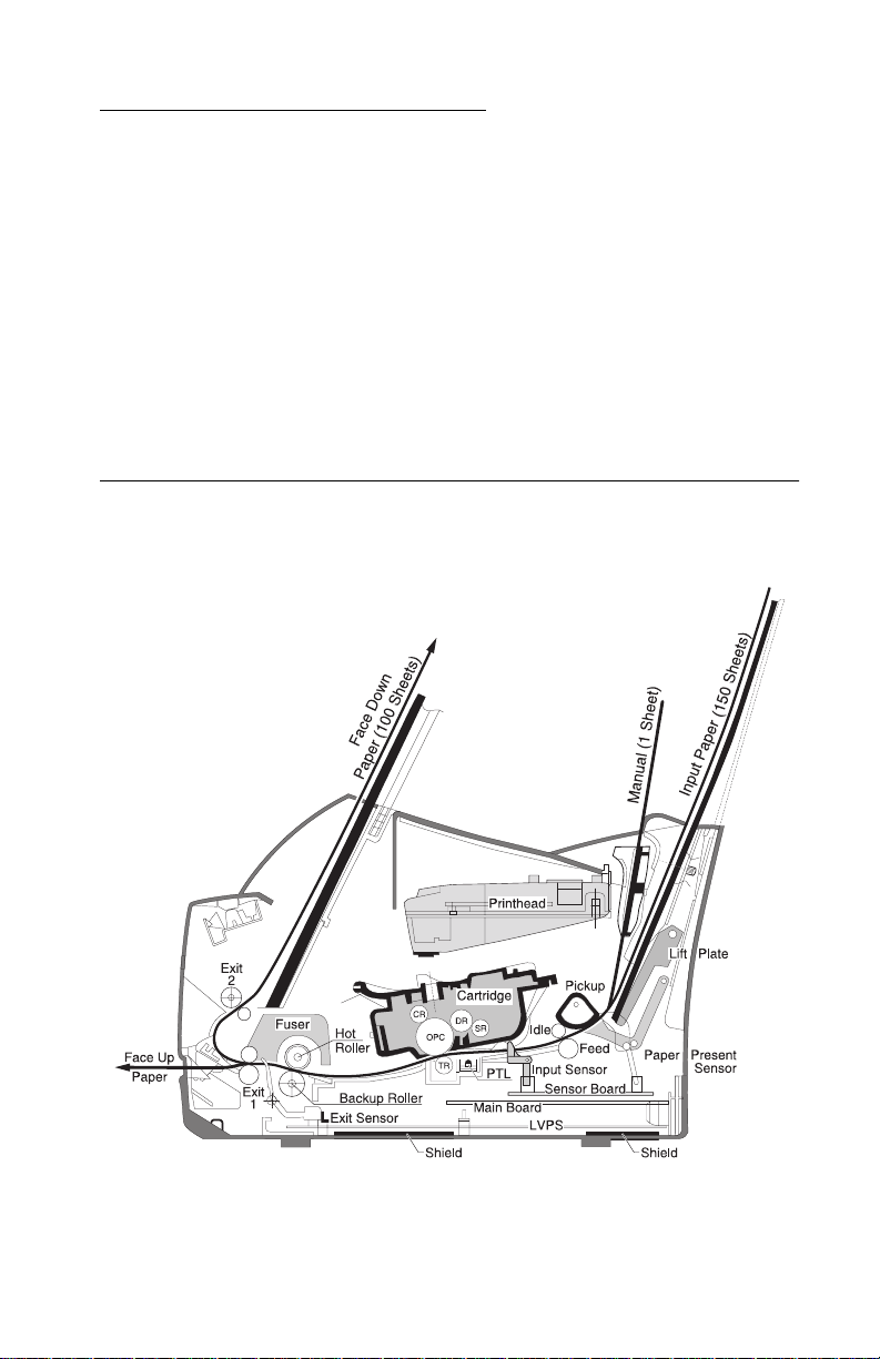
Printer Side View - Locations
General Information 1-1
Page 20

4510-001
Maintenance Approach
The diagnostic information in this manual leads you to the correct
field replaceable unit (FRU) or part. Use the user error messages,
and diagnostic aids to determine the printer problem and repair the
failure. After you complete the repair, perform tests as needed to
verify the repair.
Tools Required for Service
• Analog or digital multimeter
• Pliers: diagonal and needle-nose
• Screwdrivers: #1 and #2 Phillips
• Cotton Swab
Abbreviations
ESD Electrostatic Discharge
FRU Field Replaceable Unit
LED Light-Emitting Diode
PTL Pre-Transfer LED
V ac Volts alternating current
V dc Volts direct current
1-2 Service Manual
Page 21
4510-001
2. Diagnostic Aids
Print Quality
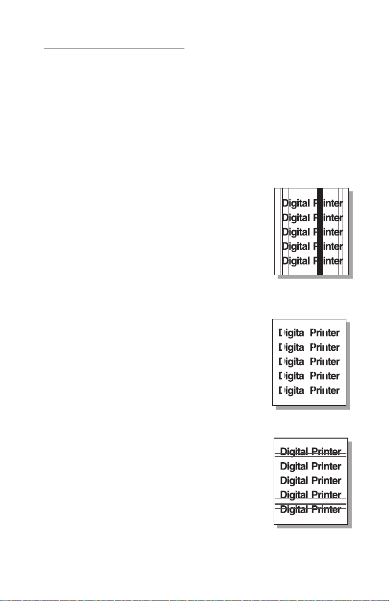
Vertical Black Line and Band
Description:
1. Straight thin black vertical line
2. Dark black vertical bands
Possible causes:
• Toner cartridge failure
• Foreign material between transfer/
charge/development rollers
• Deformed transfer roller
Vertical White Line
Description: White vertical voids
Possible causes:
• Toner cartridge failure
• Printhead f ailure
• Fuser failure
Horizontal Black Band
Description: Dark or blurry horizontal stripes
Possible causes:
• Toner cartridge failure
• Bad or dirty voltage contacts
Diagnostic Aids 2-1
Page 22
4510-001
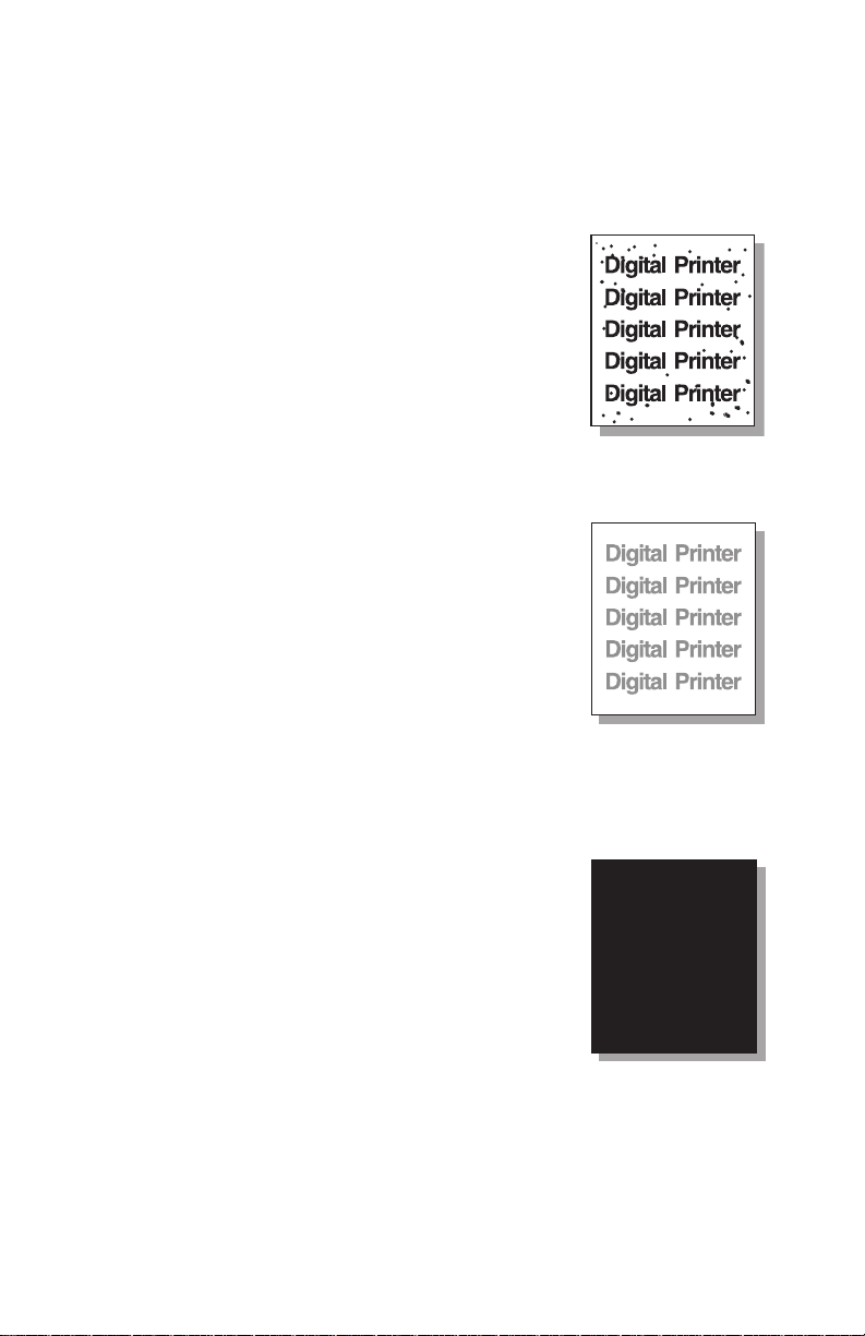
Black/White Spots
Description:
1. Dark or blurry black spots occur
periodically.
2. White spots occur periodically.
Possible Causes:
• Toner cartridge failure
• Transfer roller failure
Light Image
Description: The printed image is light, with no
residual image.
Possible causes:
• Toner save mode on
• Toner cartridge failure
• Bad or dirty voltage contacts
• HVPS failure
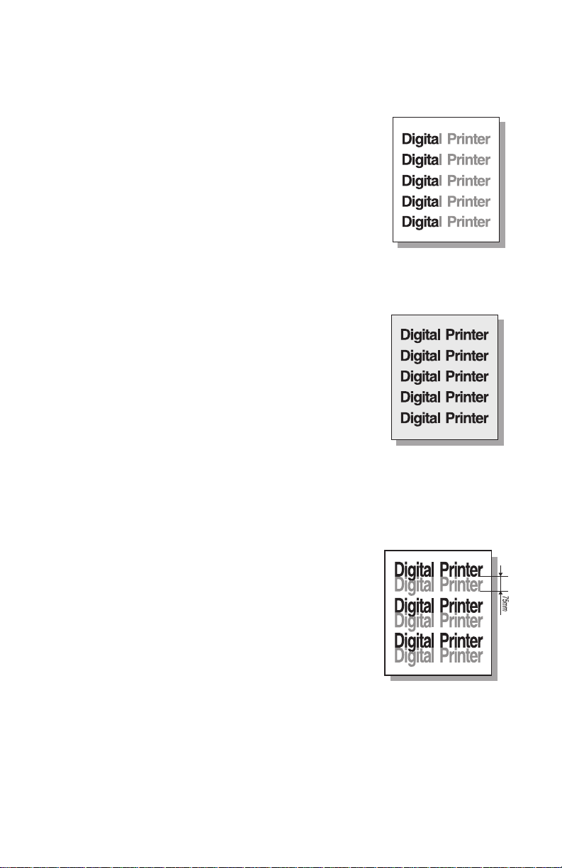
Dark or Black Image
Description: The printed image is dark.
Possible causes:
• Bad or dirty high voltage contacts
• Loose HVPS cable connection at the
engine board
• HVPS failure
2-2 Service Manual
Page 23
4510-001
Uneven Density
Description: Print density is uneven from left
to right.
Possible causes:
• Toner cartridge failure
• Improper transfer roller installation
• Transfer roller failure
Background
Description: Background appears in print
area.
Possible causes:
• Recycled or poor quality paper
• Toner cartridge failure
• Dirty transfer roll
• Transfer roll failure
• HVPS failure
Residual Image at 75 mm Intervals (1)
Description: Residual image occurs at 75
mm intervals.
Possible causes:
• Toner cartridge failure
• Bad or dirty high voltage contacts
• Transfer roller failure
• Engine board failure
Diagnostic Aids 2-3
Page 24

4510-001
Residual Image at 75 mm Intervals (2)
Description: Residual image occurs at 75
mm intervals when printing card stock or
transparencies.
Possible cause:
• Software not set to card stock or
transparency mode
Residual Image at 32 mm Intervals
Description: Residual image occurs in the
black image printing at 32 mm intervals.
Possible causes:
• Toner cartridge failure
• Bad or dirty high voltage contacts
Residual Image at 57 mm Intervals
Description: Residual image occurs at 57
mm intervals.
Possible causes:
• Fuser temperature maintained too
high. Check for toner buildup on hot
roller and thermistor surface. Clean
or replace fuser if necessary.
2-4 Service Manual
Page 25

4510-001
Toner on Front of Page
Description: The background on the front of
the printed page is stained with toner.
Possible causes:
• Toner cartridge failure
• Transfer roller failure
Toner on Back of Pa ge
Description: The back of the page is stained
with toner at 47 mm intervals.
Possible causes:
• Transfer roller failure
• Fuser failure (dirty)
Blank Page Printout (1)
Description: Blank page is printed.
Possible cause:
• Bad or dirty high voltage contacts
Diagnostic Aids 2-5
Page 26

4510-001
Blank Page Printout (2)
Description:
1. Blank page is printed.
2. One or several blank pages are printed.
3. When the printer turns on, several blank
pages print.
Possible causes:
• Bad or dirty high voltage contacts
• Pick solenoid failure
• Main board failure
Repeated marks or voids down page
Distance
Between
Repeated
Mark
Related Printer
Components
Action
27 mm Supply Roller Replace Toner Cartridge
32 mm Develop Roller Replace Toner Cartridge
37 mm Charge Roller Replace Toner Cartridge
47 mm Transfer Roller Replace Transfer Roller
58 mm Fuser Hotroll Replace Fuser
60 mm Fuser Backup Roll Replace Fuser
75 mm OPC Drum Replace Toner Cartridge
2-6 Service Manual
Page 27

4510-001
Paper Feed
Printing in wrong position
Printing begins at the
Step
wrong position on
the paper
Yes No
1 Check for obstructions
in the input tray that
could cause incorrect
feeding. Are there
obstructions?
2 Check the paper
present actuator for
binds. Is it binding?
Remove the
obstructions
Correct the
binding problem
Go to step 2
Replace the paper
present actuator
Paper stopping, jamming, or feeding multiple sheets
Paper stops or jams
Step
1 Does the paper e xit the
2 Does the paper stop
3 Is the paper jammed in
at various points in
the printer or feeds
multiple sheets
input tray? See “Paper
Path Jam 0” on
page 2-9.
just after exiting input
tray? See “Paper Path
Jam 1” on page 2-9.
front of or just inside
the fuser? See “Paper
Path Jam 2” on
page 2-10.
Yes No
Go to step 2 Go to step 4
Go to step 8 Go to step 3
Go to step 9 Go to step 7
4 Check for obstructions
in the input tray. Are
there obstructions?
Remove
obstructions
Go to step 5
Diagnostic Aids 2-7
Page 28

4510-001
Step
Paper stops or jams
at various points in
the printer or feeds
multiple sheets
Yes No
5 Clean the feed rollers.
Did this resolve the
problem?
6 Check for loose or
damaged input tray
side pads. Are they in
good condition?
7 Is the paper jammed
inside the fuser as it
exits the printer? See
“Paper Path Jam 2”
on page 2-10.
8 Check the paper feed
actuator for binding. Is
it binding?
9 Check the paper feed
actuator for dama ge or
binds. It it damaged or
binding?
10 Is the Paper LED on
after the paper exits
the printer?
11 Check the exit sensor
actuator for binds or
damage. Is it binding
or damaged?
Problem resolved Go to step 6
Replace the pa per
feed solenoid
Replace th e fuser Go to step 10
Correct the
binding or replace
the paper feed
actuator
Correct the
binding or replace
the paper feed
actuator
Go to step 11 Go to step 12
Correct the
binding or replace
the paper feed
actuator
Replace the side
pads
Replace the
sensor board
Replace the LVPS
Replace the LVPS
12 Is the pape r jammed in
the fuser?
13 Is the printer feeding
multiple sheets?
14 Did cleaning the
friction pad resolve th e
problem?
2-8 Service Manual
Replace th e fuser Go to step 13
Clean the friction
pad. Go to step 14
Problem resolved Replace the
No problem found
solenoid
Page 29

4510-001
Paper Path Jam 0
Paper Path Jam 1
Diagnostic Aids 2-9
Page 30

4510-001
Paper Path Jam 2
Service
All LEDs blinking (Printhead Error) during a print job
Step
1 Are all the printhead
2 Did printhead
3 Did main board
2-10 Service Manual
All LEDs blink when
attempting a print job
cables correctly
connected?
replacement resolve
the problem?
replacement resolve
the problem?
Yes No
Replace th e
printhead. Go to
step 2.
Problem resolved. Replace the main
Problem resolved. Replace the
Properly connect
the cables.
board. Go to
step 3.
printhead cables .
Page 31

4510-001
All LEDs blinking (Fuser Error) at power up
All LEDs blink when
Step
attempting at power upYes No
1 Check the thermostat
for continuity. Is there
continuity?
2 Check the lamp for
continuity. Is there
continuity?
3 Check the thermistor
for wear. Is the
thermistor worn?
4 Check for 110 V ac
across the 2 pins of
connector CN502 on
the LVPS. Is 110 V ac
present?
5 Check the fuser gears
for wear or other
damage. Is the gear
damaged?
Go to step 2. Replace the
thermostat.
Go to step 3. Replace the lamp.
Replace the fuser. Go to step 4.
Go to step 5. Replace LVPS.
Replace the fuser. Replace the main
board.
The LED blinks once then all other LEDs blink
(Over Heat Error)
This message is displayed when the printer detects the fuser is
hotter than it should be via feedback through the fuser thermistor.
Step Yes No
1 Replace the fuser. Did
this resolve the problem?
2 Did LVPS replacement
resolve the problem?
Problem
Resolved.
Problem
Resolved.
Replace the LVPS. Go
to step 2.
Replace the engine
board.
Diagnostic Aids 2-11
Page 32

4510-001
The LED blinks once then all other LEDs blink
(Low Heat Error)
This message occurs when the printer is warming up. If the
temperature is not correct at a certain threshold, this message is
posted.
Step Yes No
1 Check the fuser lamp. Is
the correct volta ge lamp
installed?
2 Replace the LVPS. Did
this resolve the problem?
3 Did fuser replacement
resolve the probl em ?
4 Did engine board
replacement resolve the
problem?
Go to step 2. Replace with proper
voltage lamp. Go to
step 2 if problem
persists.
Problem
Resolved.
Problem
Resolved.
Problem
resolved.
Replace the fuser. Go
to step 3.
Replace the engine
board. Go to step 4.
Replace the controller
board.
2-12 Service Manual
Page 33

4510-001
The LED blinks once then all other LEDs blink
(Open Fuser Error)
This message occurs when the printer detects no change of
temperature in the fuser
Step Yes No
1 Is there continuity across
the fuser lamp wires?
2 Remove the TCO . Is there
3 Is there continuity across
4 Replace the LVPS. Did
5 Did replacement of the
continuity across the
TCO?
the lamp?
LVPS replacement
resolve problem?
engine board resolve the
problem?
False Paper Empty Indication
Paper LED on when
Step
1 Check the paper
paper is present in
the input tray
present sensor
actuator for breakage
or binding. Is there
breakage or binding?
Yes No
Replace the pa per
present actuator.
Go to step 4. Replace the TCO.
Problem resolved.
Go to step 3. Replace the lamp.
Go to step 4. Replace the engine
Problem
Resolved.
Problem
resolved.
Problem resolved.
board. Go to step 5.
Replace the engine
board. Go to step 5.
Replace the controller
board.
Replace the
sensor board.
Diagnostic Aids 2-13
Page 34

4510-001
False Paper Present Indication
Paper LED off when
Step
paper is not present
in the input tray
Yes No
1 Check the paper
2 Replace the sensor
present sensor
actuator for breakage
or binding. Is there
breakage or binding?
board.
False Cover Open Indicator
The error LED is on
Step
1 Open the front cover
2 Disconnect the co ver
when the cover is
closed
and check the cover
open switch actuator
that is attached to the
front cover. Is the
actuator broken?
open sensor connector
from the main board.
Check for continuity at
the connector while
deflecting the actuator
on the switch. Does
the continuity change
with deflection of the
actuator?
Replace the pa per
present actuator.
Yes No
Replace th e front
cover.
Replace the main
board.
Go to step 2.
Go to step 2.
Replace the cover
open switch.
2-14 Service Manual
Page 35

4510-001
Error LED Off When Cover Open
The error LED is off
Step
when the cover is
open
Yes No
1 Disconnect the cover
open sensor connector
from the main board.
Check for continuity at
the connector while
deflecting the actuator
on the switch. Does
the continuity change
with deflection of the
actuator?
Replace th e main
board.
Drive Motor Does Not Operate
Motor does not run
Step
1 Check for proper
2 Check for continuity of
when attempting to
run a print job
connection of the
motor connector on the
SMPS board. Is it
properly connected?
the cable between the
drive motor and the
LVPS. Is there
continuity?
Yes No
Go to step 2. Properly connect
Go to step 3. Replace the cable.
Replace the cover
open switch.
the connector.
3 Replace the drive
motor. Did this resolve
the problem?
Problem resolved. Replace the LVPS.
Diagnostic Aids 2-15
Page 36

4510-001
No Power
Step
When printer power
is turned on, LEDs
not on
Yes No
1 Check the power cord
for damage a nd correct
connection. Did you
find damage or a f aulty
connection?
2 Replace the LVPS. Did
this resolve the
problem?
3 Did operator panel
replacement resolve
the problem?
Repair or replace
the power cord as
necessary.
Problem resolved. Replace the
Problem resolved. Replace main
Go to step 2.
operator panel.
board.
2-16 Service Manual
Page 37

4510-001
3. Repair Information
Handling ESD-Sensitive P arts
Many electronic products use parts that are known to be sensitive to
electrostatic discharge (ESD). To prevent damage to ESD-sensitive
parts, follow the instructions below in addition to all the usual
precautions, such as turning off power before removing logic boards:
• Keep the ESD-sensitive part in its ori gi nal shipping container
(a special “ESD bag”) until you are ready to install the part into
the printer.
• Make the least-possible movements with your body to prevent
an increase of static electricity from clothing fibers, carpets, and
furniture.
• Secure the ESD wrist strap around your wrist and connect the
wrist band to the engine ground point. This discharges any
static electricity, in your body, to the printer.
• Hold the ESD-sensitive part by its edge connector shroud
(cover); do not touch the pins. If you are removing a pluggable
module, use the correct tool.
• Do not place the ESD-sensitive part on the printer cover or on a
metal table, as electrical grounding may occur, which increases
the risk of damage due to the discharge path your body could
establish through the ESD-sensitive part. (Large metal objects
can be discharge paths without being grounded.)
• When laying the ESD-sensitive part down, always return it to
the ESD-sensitive bag.
• If possible, keep all ESD-sensitive parts in a grounded metal
cabinet (case).
• Take care working with ESD-sensitive parts when cold weather
heating is used, as low humidity increases static electricity.
Repair Information 3-1
Page 38

4510-001
Front Cover
1. Pull the cover open.
2. Remove the screw and remove the stopper that holds the
printer cover.
3-2 Service Manual
Page 39

4510-001
3. Pull the right lower side off the post and to the right. Then push
the cover in the direction of the arrow to loosen the lower left
part.
Repair Information 3-3
Page 40

4510-001
4. Remove the screw that secures the operator panel harness
cover, disconnect the connector and remove the cover.
3-4 Service Manual
Page 41

4510-001
Other Covers
1. Rear Cover: Remove the cover in the direction of (a).
2. Top Cover: Remove the cover in the direction of (b).
3. Side cover L, R: Remove the cover in the direction of (c).
Repair Information 3-5
Page 42

4510-001
Operator Panel
1. Before removing the operator panel, you should remove the
front cover.
2. Remove two screws of the operator panel cover, and widen the
hooks (a) (b) (c) to remove.
3-6 Service Manual
Page 43

4510-001
3. Remove two screws, and remove the operator panel.
4. Remove the operator panel from the operator panel cover.
Repair Information 3-7
Page 44

4510-001
Printhead
1. Before removing the printhead, remove the rear cover and the
top cover.
2. Remove three screws securing the printhead.
3-8 Service Manual
Page 45

4510-001
3. Remove two connectors from the printhead, and then remove
the printhead.
Repair Information 3-9
Page 46

4510-001
Transfer Roller
1. Open the front cover.
2. Use a flat blade screwdriver to pry the right end of the roller up
and remove the transfer roller.
3-10 Service Manual
Page 47

4510-001
Motor Assembly
1. Before removing the motor assembly, remove the front cover,
top cover, rear cover, right side cover, and the metal bottom
cover.
2. Remove five screws securing the motor assembly and remove a
connector from the motor assembly. Then remove the motor
assembly.
Pick Roller Clutch Solenoid
1. Before removing the solenoid, remove the top cover, rear cover,
right side cover and the metal bottom cover.
2. Disconnect the solenoid connector from the LVPS.
3. Remove the screw securing the solenoid.
4. Remove the solenoid.
Repair Information 3-11
Page 48

4510-001
HVPS Board
1. Before removing the HVPS board, remove the top cover, rear
cover, and left side cover.
2. Remove four screws and a connector from the HVPS board,
and then remove board.
Note: When you reassemble the HVPS board, make sure that the
five terminals are in place.
3-12 Service Manual
Page 49

4510-001
Fuser Assembly
1. Before rem oving t he fuser a ssembl y, remove the front co ve r and
left cover.
2. Remove two terminal screws and a connector.
Repair Information 3-13
Page 50

4510-001
3. Remove remaining screws. Use a flat blade screwdriver to
unlatch the fuser assembly and remove.
3-14 Service Manual
Page 51

4510-001
Fuser Thermostat and Lamp
1. Remove screw from the fuser assembly and remove the
thermostat cover. Remove the two screws securing the
thermostat.
Repair Information 3-15
Page 52

4510-001
2. Remove two screws from the fuser assembly, and remove the
hot roller.
3. Remove the lamp from the hot roller.
Note: When you reassemble the lamp, handle it with care as it is
fragile.
3-16 Service Manual
Page 53

4510-001
LVPS Board
1. Before removing the L VPS board, remove the rear cover.
2. Remove two screws.
Repair Information 3-17
Page 54

4510-001
3. Remove the screws and remove the bottom cover.
3-18 Service Manual
Page 55

4510-001
4. Unplug connector (CN5) from the main board and connectors
(CN1, CN2, CN501, CN502) from LVPS. Remove the clip that
secures the LVPS to the metal bottom pan. Remove five screws
from the LVPS and remove the LVPS board.
Repair Information 3-19
Page 56

4510-001
Main Board and Input/Exit Sensor Board
1. Before removing the main board, remove the rear cover, metal
bottom cover, and the LVPS board.
2. Unplug all connectors, remove two screws from the main board,
and then remove the board.
3. To remove the input/exit sensor board, release four snap-fits
securing the insulator and then remove the insulator.
3-20 Service Manual
Page 57

4510-001
4. Release four snap-fits securing the sensor board and then
remove the input/exit sensor board.
Pre-Transfer LED Assembly (PTL)
1. Remove the transfer roller.
2. Remove the bottom metal cover and disconnect CN6 on the
main board.
3. Remove the four screws securing the printhead plate.
4. Slide the printhead plate left to disengage the pick roller from
the pick roller shaft.
5. Remove the two screws securing the PTL cover plate.
6. Remove the PTL.
Repair Information 3-21
Page 58

4510-001
Pick Roller
There is more than one way to remove the pick roller, but the
procedure below is the easiest.
1. Open the front cover, and remove the toner cartridge.
2. Remove the rear and top covers along with the paper input tray
assembly.
3. Remove the four screws securing the printhead bracket to the
plastic frame.
4. Lift the printhead bracket (with printhead still attached) upward
and to the left to disconnect the pick roller assembly from the
pick roller shaft.
5. Remove two screws securing the pick roller assembly to the
printhead bracket.
6. Remove the pick roller assembly from the bracket.
3-22 Service Manual
Page 59

4510-001
Installation Note:
When repositioning the printhead bracket (with the pick roller
assembly) to the plastic frame, push the lift plate down while
carefully engaging the pick roller shaft to the pick roller assembly.
This procedure is to ensure the lift plate properly rests under the pick
roller.
Repair Information 3-23
Page 60

4510-001
3-24 Service Manual
Page 61

4510-001
4. Parts Catalog
Parts Catalog 4-1
Page 62

4510-001
Assembly 1: Co vers
4-2 Service Manual
Page 63

4510-001
Assembly 1: Covers
AsmIndex
1-1 12G6768 1 Tray Assembly, Input
2 12G6765 1 Cover Assembly, Rear
3 12G6763 1 Extender , Paper Exit
4 12G6760 1 Guide, Stacker
5 12G6767 1 Cover, Right
6 12G6762 1 Cover, Front
7 12G6255 1 Support, Cover Open
8 12G6761 1 Panel, Operator
9 12G6796 1 Cover, Operator Panel
10 12G6776 1 Cable, Operato r Panel
11 12G6766 1 Cover , Lef t
12 12G6764 1 Cover , Top
Part
Number
Unit Description
Parts Catalog 4-3
Page 64

4510-001
Assembly 2: Engine
4-4 Service Manual
Page 65

4510-001
Assembly 2: Engine
AsmIndex
2-1 12G6795 1 Printhead Assembly Complete
2 12G6256 1 Plate, Printhead Mount
3 12G6784 1 Shaft, Pick Roller
4 12G6777 1 Plate, Lift
5 12G6259 1 Bushing, Transfer Roll Right
6 12G6262 1 Spring, Bushing, Right
7 12G6269 1 Housing, Transfer Roll Bushing
8 12G6785 1 Pad, Left Separator
9 12G6786 1 Pad, Right Separator
10 12G6778 1 Holder, Pad
11 12G6779 1 Pad, Main Separator
12 12G6769 1 Frame, Lo w er
13 12G6783 1 Solenoid, Pick Roller Clutch
14 12G6780 1 Clutch Assembly, Pick Roller Gear
15 12G6265 1 Bushing, Shaft
16 12G6771 1 Fan, Cooling
17 12G6266 1 Roller, Paper Feed
18 12G6798 1 Motor, Main
19 12G6794 1 Drive Assembly, Main
20 12G6799 1 Cable, Main Motor
22 12G6782 1 Card Assembly, Input/Exit Sensor
23 12G6267 1 Housing, Paper Feed Roller
24 12G6789 1 Flag, Exit Sensor
25 12G6788 1 Flag, Input Sensor
26 12G6263 1 Holder, Exit Roller
27 12G6257 1 Switch, Cover Open
Part
Number
Unit Description
Parts Catalog 4-5
Page 66

4510-001
Assembly 2 (cont.): Engine
4-6 Service Manual
Page 67

4510-001
Assembly 2 (cont.): Engine
AsmIndex
2-28 12G6787 1 Roll Assembly, Pick
29 12G6781 1 Contact Assembly, Toner Cartridge
30 12G6770 1 Roller, Transfer
31 12G6261 1 Spring, Bushing, Left
32 12G6260 1 Bushing, Transfer Roll Left
33 12G6258 1 Card Assembly, Pre-Transfer LED
34 12G6264 1 Cover, PTL Board
35 12G6797 1 Cable, Printhead
Part
Number
Unit Description
Parts Catalog 4-7
Page 68

4510-001
Assembly 3: Fuser
4-8 Service Manual
Page 69

4510-001
Assembly 3: Fuser
AsmIndex
3-1 12G6772 1 Fuser Assembly, Complete, 220 V
1 12G6773 1 Fuser Assembly, Complete, 110 V
2 12G0075 1 Thermostat (TCO)
3 12G6774 1 Lamp, Fuser, 220 V
3 12G6775 1 Lamp, Fuser, 110 V
Part
Number
Unit Description
Parts Catalog 4-9
Page 70

4510-001
Assembly 4: Electronics
4-10 Service Manual
Page 71

4510-001
Assembly 4: Electronics
AsmIndex
4-1 12G6790 1 Card Assembly, Main
2 12G6791 1 Power Supply, Low Voltage, 220 V
2 12G6792 1 Power Supply, Low Voltage, 110 V
3 12G6793 1 Power Supply, High Voltage
Part
Number
Unit Description
Parts Catalog 4-11
Page 72

4510-001
4-12 Service Manual
Page 73

4510-001
Index
A
Abbreviations 1-2
E
ESD-Sensitive Parts 3-1
P
Paper Feed 2-7
Parts Catalog
Print Quality
4-1
2-1
R
Removals
Front Cover
Fuser Assembly
Fuser Thermostat and Lamp
HVPS Board
LVPS Board
Main Board and Sensor Board
Motor Assembly
Operator Panel
Other Covers
Pick Roller Clutch
Pre-Transfer LED Assembly (PTL)
Printhead
Transfer Roller
Repair Information
3-2
3-13
3-15
3-12
3-17
3-20
3-11
3-6
3-5
3-11
3-21
3-8
3-10
3-1
S
Safety Information xiii
2-10
Service
T
Tools 1-2
Part Numbers
12G0075 4-9
12G6255
4-3
12G6256
12G6257
12G6258
12G6259
12G6260
12G6261
12G6262
12G6263
12G6264
12G6265
12G6266
12G6267
12G6269
12G6760
12G6761
12G6762
12G6763
12G6764
12G6765
12G6766
12G6767
12G6768
12G6769
12G6770
12G6771
12G6772
12G6773
12g6774
12G6775
12G6776
12G6777
12G6778
12G6779
12G6780
12G6781
12G6782
12G6783
12G6784
12G6785
12G6786
12G6787
12G6788
12G6789
4-5
4-5
4-7
4-5
4-7
4-7
4-5
4-5
4-7
4-5
4-5
4-5
4-5
4-3
4-3
4-3
4-3
4-3
4-3
4-3
4-3
4-3
4-5
4-7
4-5
4-9
4-9
4-9
4-9
4-3
4-5
4-5
4-5
4-5
4-7
4-5
4-5
4-5
4-5
4-5
4-7
4-5
4-5
Index I-1
Page 74

4510-001
12G6790 4-11
12G6791
12G6792
12G6793
12G6794
12G6795
12G6796
12G6797
12G6798
12G6799
4-11
4-11
4-11
4-5
4-5
4-3
4-7
4-5
4-5
I-2 Service Manual
 Loading...