

Page 1

CX421, CX522, CX622, CX625,
MC2325, MC2425, MC2535,
MC2640, XC2235, XC4240
7529-081, 23x, 4x6, 6x6, 83x
Service Manual
• Start diagnostics
• Maintenance
• Safety and notices
• Trademarks
• Index
June 29, 2018 www.lexmark.com
Page 2

7529
Product information
Product name:
Lexmark CX421adn; Lexmark CX522ade; Lexmark CX622ade; Lexmark CX625ade, CX625adhe, CX625adthe; Lexmark
MC2325adw; Lexmark MC2425adw; Lexmark MC2535adw; Lexmark MC2640adwe; Lexmark XC2235; Lexmark XC4240
Machine type:
7529
Model(s):
081, 230, 238, 436, 486, 496, 636, 686, 836, 838, 898
Edition notice
June 29, 2018
The following paragraph does not apply to any country where such provisions are inconsistent with local law: LEXMARK
INTERNATIONAL, INC., PROVIDES THIS PUBLICATION “AS IS” WITHOUT WARRANTY OF ANY KIND, EITHER EXPRESS OR
IMPLIED, INCLUDING, BUT NOT LIMITED TO, THE IMPLIED WARRANTIES OF MERCHANTABILITY OR FITNESS FOR A PARTICULAR
PURPOSE. Some states do not allow disclaimer of express or implied warranties in certain transactions; therefore, this statement
may not apply to you.
References in this publication to products, programs, or services do not imply that the manufacturer intends to make these available
in all countries in which it operates. Any reference to a product, program, or service is not intended to state or imply that only that
product, program, or service may be used. Any functionally equivalent product, program, or service that does not infringe any
existing intellectual property right may be used instead. Evaluation and verification of operation in conjunction with other products,
programs, or services, except those expressly designated by the manufacturer, are the user’s responsibility.
Trademarks
Lexmark and the Lexmark logo are trademarks of Lexmark International, Inc., registered in the United States and/or other countries.
PCL® is a registered trademark of the Hewlett-Packard Company. PCL is Hewlett-Packard Company’s designation of a set of printer
commands (language) and functions included in its printer products. This printer is intended to be compatible with the PCL language.
This means the printer recognizes PCL commands used in various application programs, and that the printer emulates the functions
corresponding to the commands.
PostScript is a registered trademark of Adobe Systems Incorporated in the United States and/or other countries.
All other trademarks are the property of their respective owners.
© 2018 Lexmark International, Inc.
All rights reserved.
P/N
Page 3
7529
General information
Printer model configurations
The LexmarkTM CX421, CX522, CX622, CX625, MC2325, MC2425, MC2535, MC2640, XC2235, XC4240
printers are network‑capable, multifunction laser printers. The printers support color and monochrome printing
and are embedded with home screen solutions and applications. All information in this service manual pertains
to all models unless explicitly noted.
The printers are available in the following models:
Model Configurations Machine type/model
CX421adn Network-ready color laser printer with 2.4" color
display, analog fax, internal duplex printing, and duplex
scanning for small workgroups
CX522ade Network-ready color laser printer with 4.3” color touch
screen, analog fax, internal duplex printing, and duplex
scanning for small workgroups
CX622ade Network-ready color laser printer with 4.3” color touch
screen, analog fax, internal duplex printing, and duplex
scanning for medium workgroups
CX625ade Network-ready color laser printer with 7” color touch
screen, analog fax, internal duplex printing, and duplex
scanning for medium workgroups
CX625adhe Network-ready color laser printer with 7” color touch
screen, analog fax, standard hard disk, headphone
jack, internal duplex printing, and duplex scanning for
medium workgroups
MC2325adw Network-ready color laser printer with 2.4" color
display, wireless, analog fax, internal duplex printing,
and simplex scanning for small workgroups
MC2425adw Network-ready color laser printer with 2-line APA
display, internal duplex printing, and wireless
connectivity for small workgroups
7529‑230
7529‑436
7529‑636
7529‑836
7529‑838
7529‑081
7529‑238
MC2535adwe Network-ready color laser printer with 4.3” color touch
screen, analog fax, internal duplex printing, and duplex
scanning for small workgroups
MC2640adwe Network-ready color laser printer with 4.3” color touch
screen, analog fax, internal duplex printing, and duplex
scanning for medium workgroups
XC2235 Network-ready color laser printer with 4.3” color touch
screen, analog fax, internal duplex printing, and duplex
scanning for small workgroups
XC4240 Network-ready color laser printer with 7” color touch
screen, analog fax, standard hard disk, headphone
jack, internal duplex printing, and duplex scanning for
medium workgroups
General information
23
7529‑486
7529‑686
7529‑496
7529‑898
Page 4

Parts catalog
Legend
The following column headings are used in the parts catalog:
• Asm‑index—Identifies the item in the illustration
• P/N—Identifies the part number of a FRU
• Units/mach—Refers to the number of units in a printer
• Units/opt—Refers to the number of units in an option
• Units/FRU—Refers to the number of units in a FRU
• Description—A brief description of the part
The following abbreviations are used in the parts catalog:
• NS (not shown) in the Asm‑index column indicates that the part is procurable but is not shown in the
illustration.
• PP (parts packet) in the Description column indicates that the part is contained in a parts packet.
7529
Parts catalog
448
Page 5
Assembly 1: 2.4-inch control panel
7529
Parts catalog
449
Page 6
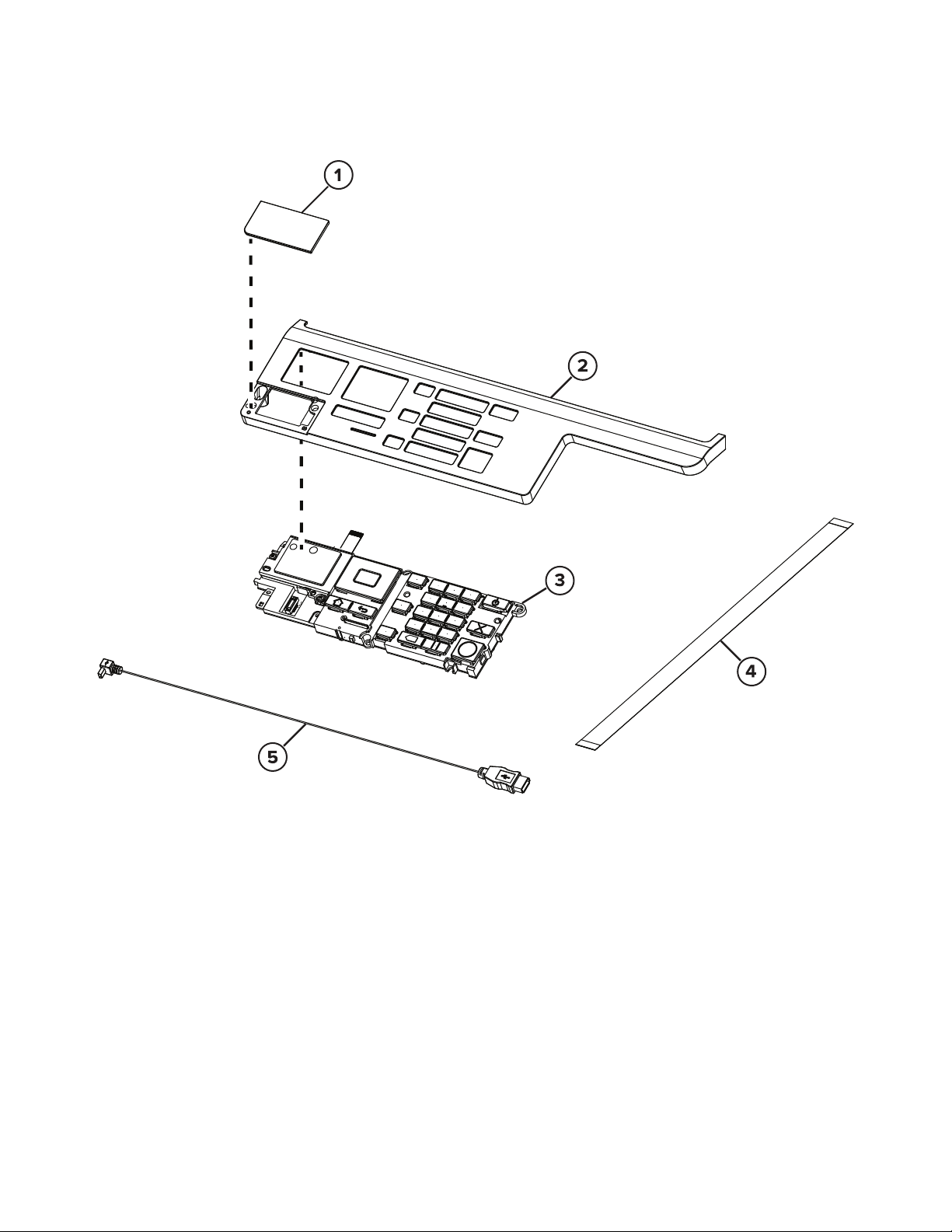
Assembly 1: 2.4-inch control panel
Asm-index P/N Units/mach Units/FRU Description Removal procedure
7529
1 41X2056 1 1 MC2325 control panel
badge cover
1 41X2131 1 1 MC2425 control panel
badge cover
1 41X2057 1 1 CX321 control panel
badge cover
1 41X2065 1 1 CX421 control panel
badge cover
2 41X1044 1 1 2.4-inch control panel
top cover
341X1368 1 12.4-inch control panel
assembly
4 41X2024 1 1 2.4-inch control panel
ribbon cable
541X2023 1 1USB cable --
“2.4‑inch control panel badge cover
removal” on page 322
“2.4‑inch control panel badge cover
removal” on page 322
“2.4‑inch control panel badge cover
removal” on page 322
“2.4‑inch control panel badge cover
removal” on page 322
“2.4‑inch control panel top cover and
control panel removal” on page 325
“2.4‑inch control panel top cover and
control panel removal” on page 325
“2.4‑inch control panel top cover and
control panel removal” on page 325
Parts catalog
450
Page 7
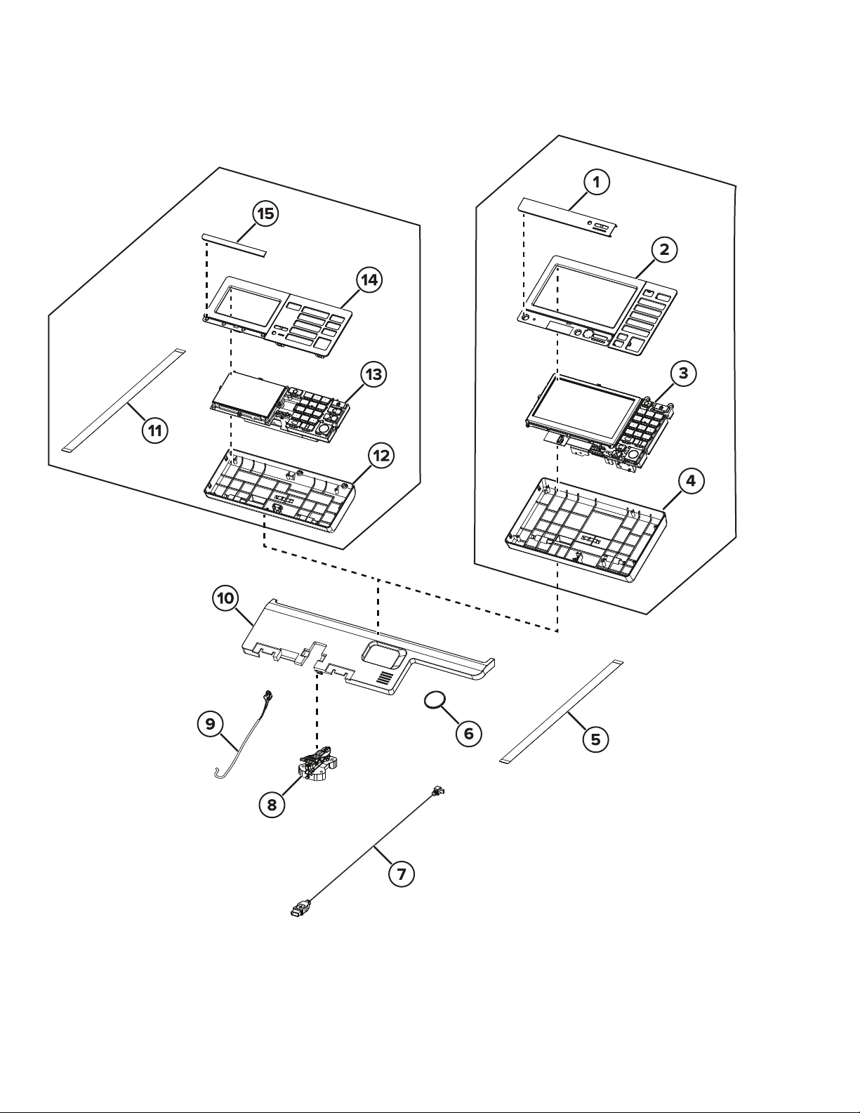
Assembly 2: 4.3-inch and 7-inch control panel
7529
Parts catalog
451
Page 8
Assembly 2: 4.3-inch and 7-inch control panel
Asm-index P/N Units/mach Units/FRU Description Removal procedure
7529
141X2128 1 1CX625 control panel badge
cover
1 41X2129 1 1 XC4240 control panel badge
cover
2 41X0543 1 1 7-inch control panel bezel
(CX625 and XC2420)
3 41X0051 1 1 7-inch control panel
assembly (CX625 and
XC2420)
4 41X1048 1 1 7-inch control panel base
cover (CX625 and XC2420)
5 41X2025 1 1 7-inch control panel ribbon
cable (CX625 and XC2420)
6 40X6517 1 1 Speaker (MC2325, CX421,
and MC2425)
6 41X1311 1 1 Speaker (CX522, CX622,
CX625, XC2235, XC4240,
MC2325, MC2425, MC2535,
and MC2640)
741X2023 1 1USB cable --
“7‑inch control panel badge cover
removal” on page 323
“7‑inch control panel badge cover
removal” on page 323
“7‑inch control panel bezel
removal” on page 324
“7‑inch control panel removal” on
page 330
“7‑inch control panel removal” on
page 330
“7‑inch control panel removal” on
page 330
“Speaker (MC2325, CX421,
MC2425) removal” on page 331
“Speaker (CX522, CX622,
CX625, XC2235, XC4240,
MC2535, MC2640) removal” on
page 332
8 41X1047 1 1 Control panel rotation arm --
9 41X2306 1 1 Headphone cable with clip --
10 41X1045 1 1 Scanner top front cover --
11 41X2024 1 1 4.3-inch control panel ribbon
cable (CX522, CX622,
MC2535, and XC2235)
12 41X1046 1 1 4.3-inch control panel base
cover (CX522, CX622,
MC2535, and XC2235)
13 41X1359 1 1 4.3-inch control panel
assembly (CX522, CX622,
MC2535, and XC2235)
14 41X1727 1 1 4.3-inch control panel bezel
(CX522, CX622, MC2535,
and XC2235)
15 41X2130 1 1 MC2535 control panel
badge cover
15 41X2058 1 1 CX522 control panel badge
cover
“4.3‑inch control panel removal”
on page 329
--
“4.3‑inch control panel removal”
on page 329
“4.3‑inch control panel bezel
removal” on page 323
“4.3‑inch control panel badge
cover removal” on page 322
“4.3‑inch control panel badge
cover removal” on page 322
Parts catalog
452
Page 9

Asm-index P/N Units/mach Units/FRU Description Removal procedure
7529
15 41X2059 1 1 XC2235 control panel badge
cover
15 41X2067 1 1 CX622 control panel badge
cover
NS 41X1731 1 1 Front bracket cover
NS 41X2022 1 1 Control panel power cable --
“4.3‑inch control panel badge
cover removal” on page 322
“4.3‑inch control panel badge
cover removal” on page 322
“Front bracket cover removal” on
page 331
Parts catalog
453
Page 10

7529
Parts catalog
454
Page 11

7529
Parts catalog
455
Page 12

Assembly 3: Covers
7529
Parts catalog
456
Page 13

Assembly 3: Covers
Asm-index P/N Units/mach Units/FRU Description Removal procedure
7529
141X1295 1 1Output bin
2 41X1288 1 1 MFP cable cover --
3 41X1284 1 1 Top cover with fan
4 41X2114 1 1 Front toner door pivot
bracket
541X0397 1 1System fan
6 41X1787 1 1 Rear cover (CX622,
CX625, MC2640, and
XC4240)
6 41X2101 1 1 Rear cover (CX522 and
MC2535)
6 41X2102 1 1 Rear cover (CX421 and
MC2425)
6 41X2104 1 1 Rear cover (CX321 and
MC2325)
7 41X1296 1 1 MFP link
8 41X1049 1 1 Toner cover with damper
“Output bin and paper bail removal”
on page 375
“Top cover removal” on page 371
“Flatbed pivot link (front left)
removal” on page 409
“System fan removal” on page 365
“Rear cover removal” on page 367
“Rear cover removal” on page 367
“Rear cover removal” on page 367
“Rear cover removal” on page 367
“MFP link removal” on page 378
“MFP toner cover removal” on
page 377
940X7823 1 1Right cover
10 41X1285 1 1 250-sheet tray --
11 40X7619 1 2 Door straps --
12 41X1286 1 1 Front door
13 41X1287 1 1 Front middle cover
14 41X1291 1 1 Left cover
“Right cover removal” on page 294
“Front door removal” on page 316
“Front middle cover removal” on
page 320
“Left cover removal” on page 284
Parts catalog
457
Page 14

7529
Parts catalog
458
Page 15

Assembly 4: Paper path and frame
7529
Parts catalog
459
Page 16

Assembly 4: Paper path and frame
Asm-index P/N Units/mach Units/FRU Description Removal procedure
7529
1 41X2307 1 1 Narrow media sensor
flag
2 40X8819 1 1 Right fuser deflector
3 41X1041 1 1 110 V Fuser
3 41X1300 1 1 220 V Fuser
3 41X1299 1 1 100 V Fuser
441X1040 1 1Printhead
5 40X7629 1 1 Motor (fuser drive)
6 41X2327 1 1 Subframe cable cover --
7 41X1312 1 1 Lower right subframe
840X5168 2 2Pick tires
9 41X1292 1 1 Media feeder
10 41X1039 1 1 Imaging kit
11 41X0580 1 1 Transfer module guide
“Narrow media sensor flag removal” on
page 382
“MFP fuser deflector flag removal” on
page 380
“Fuser removal” on page 336
“Fuser removal” on page 336
“Fuser removal” on page 336
“Printhead removal” on page 383
“Motor (fuser drive) removal” on
page 295
“Lower right frame removal” on
page 351
“Pick tires removal” on page 341
“Tray 1 media feeder removal” on
page 362
“Imaging kit removal” on page 311
“Transfer module guide removal” on
page 358
12 41X2326 1 1 Lower left subframe
13 41X1724 1 1 Drive unit motor kit
14 41X1289 1 1 EP drive assembly
NS 41X2360 4 4 Sub‑frame foot --
“Lower left frame removal” on
page 343
“Motor (drive unit) removal” on
page 286
“EP drive assembly removal” on
page 286
Parts catalog
460
Page 17

Assembly 5: Electronics
7529
Parts catalog
461
Page 18

Assembly 5: Electronics
Asm-index P/N Units/mach Units/FRU Description Removal procedure
7529
1 41X1785 1 1 Controller board (CX321,
MC2325, CX421, and
MC2425)
1 41X2099 1 1 Controller board (CX522
and MC2535)
1 41X1786 1 1 Controller board (CX622,
CX625, MC2640, and
XC4240)
2 40X7620 1 1 Toner meter card
3 41X1042 1 1 High‑voltage power supply
4 40X7301 4 1 Photo sensors:
• Sensor (tray present)
• Sensor (duplex)
• Sensor (bin full/narrow
media)
5 41X1290 1 1 Weather station
6 40X5413 1 1 Sensor (fuser exit)
“Controller board removal” on
page 369
“Controller board removal” on
page 369
“Controller board removal” on
page 369
“TMC card removal” on page 296
“HVPS removal” on page 302
“Sensor (tray present) removal” on
page 361
“Sensor (duplex) removal” on
page 357
“Sensor (narrow media) removal”
on page 381
“Weather station removal” on
page 332
“Sensor (fuser exit) removal” on
page 291
7 41X1043 1 1 Low-voltage power supply
(170 W)
“LVPS removal” on page 289
Parts catalog
462
Page 19

Assembly 6: Cables and sensors
7529
5H
5F
5G
5E
5D
5C
Parts catalog
463
5B
5A
Page 20

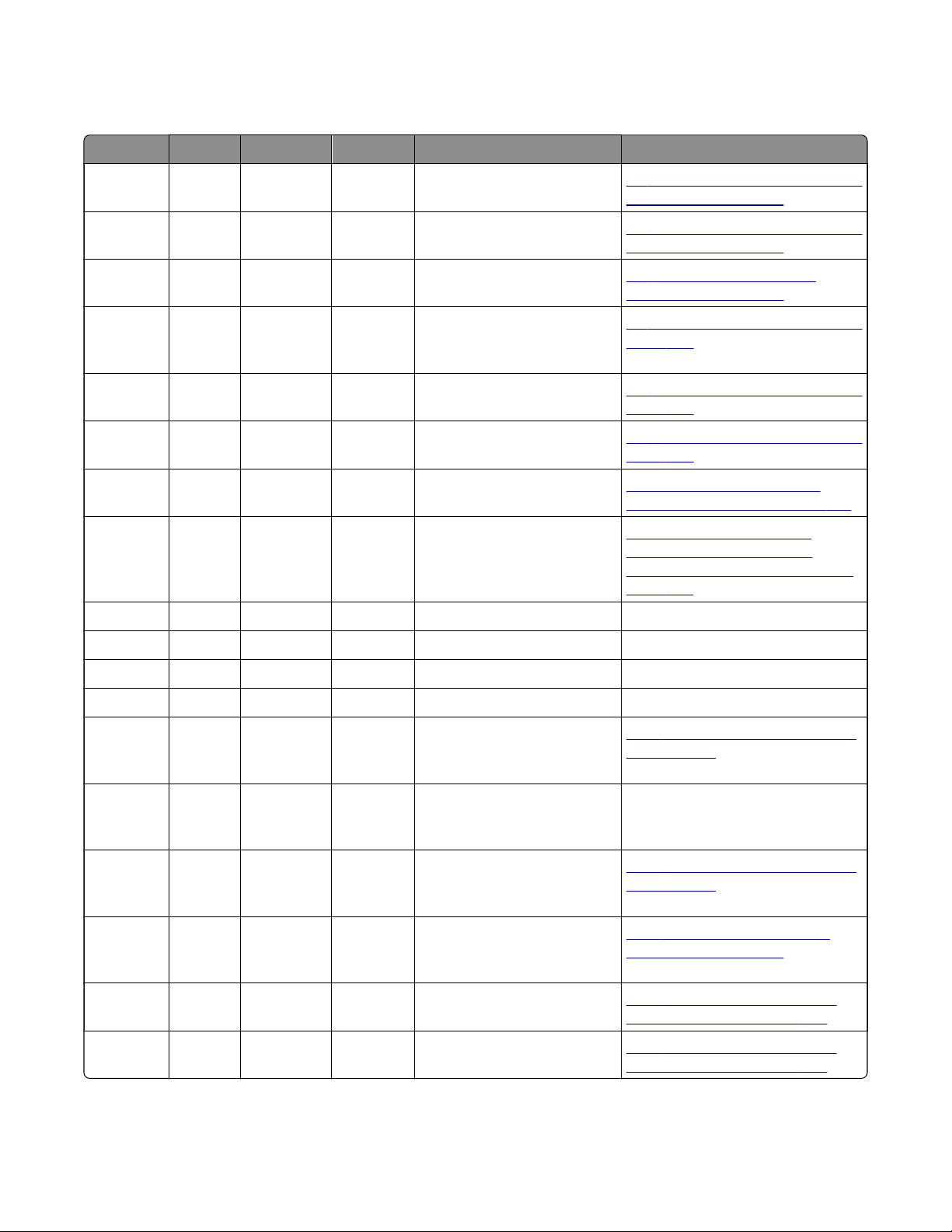
Assembly 6: Cables and sensors
Asm-index P/N Units/mach Units/FRU Description Removal procedure
7529
1 41X1904 1 1 Sensor (left toner patch with
thermistor)
2 41X2348 1 1 Sensor (right toner patch with
thermistor)
3 41X1722 1 1 Waste toner bottle contact
block
4 41X1723 4 1 Toner cartridge contact
5A 41X2328 1 1 Fuser exit narrow media to
controller board
5B 41X2329 1 1 Fuser/input sensor cable --
5C 41X2332 1 1 LVPS to controller board cable --
5D 41X2330 1 1 EP motor to controller board
cable
5E 41X2335 1 1 Tray 2 to controller board cable --
5F 41X2334 1 1 HVPS to controller board cable --
5G 41X2336 1 1 Tray present sensor cable --
5H 41X2331 1 1 AC power to LVPS cable --
“Sensors (toner patch)
removal” on page 299
“Sensors (toner patch)
removal” on page 299
“Waste toner bottle contact
block removal” on page 315
“Toner cartridge contacts
removal” on page 313
--
--
6 40X7641 1 1 Control panel and USB port
cable pack
7 41X1561 1 1 Front and right side interlock
switch cover assembly
NS 41X2333 1 1 Weather station cable
--
“Interlock switch cover
assembly removal” on
page 320
“Weather station removal” on
page 332
Parts catalog
464
Page 21

Assembly 7: Scanner
7529
Parts catalog
465
Page 22

Assembly 7: Scanner
Asm-index P/N Units/mach Units/FRU Description Removal procedure
7529
1 41X1294 1 1 Flatbed scanner
assembly (CX321,
MC2325, CX421,
MC2425, CX522, and
MC2535)
1 41X2071 1 1 Flatbed scanner
assembly (CX622,
CX625, MC2640, and
XC4240)
2 41X1282 1 1 Flatbed pivot link (rear
right)
341X1560 1 1Release lever
4 41X1281 1 1 Scanner right cover
5 41X2126 1 1 Bin full flag
6 41X1559 1 1 Redrive unit
7 41X1283 1 1 Flatbed pivot link (front
left)
“Flatbed scanner assembly
removal” on page 403
“Flatbed scanner assembly
removal” on page 403
“Flatbed pivot link (rear right)
removal” on page 408
“Release lever removal” on
page 379
“Scanner right cover removal” on
page 402
“Bin full flag removal” on page 380
“Redrive unit removal” on page
385
“Flatbed pivot link (front left)
removal” on page 409
NS 40X2252 2 2 Redrive spacer screws --
Parts catalog
466
Page 23

Assembly 8: ADF
7529
Parts catalog
467
Page 24

Assembly 8: ADF
Asm-index P/N Units/mach Units/FRU Description Removal procedure
7529
1 41X1276 1 1 ADF assembly (CX421,
MC2425, CX522, and MC2535)
1 41X1293 1 1 ADF assembly (CX622, CX625,
MC2640, and XC4240)
1 41X1275 1 1 ADF assembly (CX321 and
MC2325)
2 41X1333 1 1 ADF tray (CX321, MC2325,
CX421, MC2425, CX522, and
MC2535)
2 41X1335 1 1 ADF tray (CX622, CX625,
MC2640, and XC4240)
3 40X8734 1 1 ADF right hinge --
4 41X1974 1 1 Flatbed cushion --
5 40X8735 1 1 ADF left hinge --
6 41X2116 1 1 ADF top cover assembly (CX321
and MC2325)
6 41X2117 1 1 ADF top cover assembly
(CX622, CX625, MC2640, and
XC4240)
“ADF assembly removal
(SADF/RADF)” on page 386
“ADF assembly removal
(DADF)” on page 389
“ADF assembly removal
(SADF/RADF)” on page 386
“ADF tray removal” on
page 395
“ADF tray removal” on
page 395
“ADF top cover removal” on
page 398
“ADF top cover removal” on
page 398
6 41X2118 1 1 ADF top cover assembly
(CX421, MC2425, CX522, and
MC2535)
7 40X8736 1 1 ADF pick roller (CX321,
MC2325, CX421, MC2425,
CX522, and MC2535)
7 41X1326 1 1 ADF pick roller (CX622, CX625,
MC2640, and XC4240)
8 40X6247 1 1 ADF separator pad (CX321 and
MC2325)
8 41X0917 1 1 ADF separator roller (CX421,
MC2425, CX522, and MC2535)
8 41X1325 1 1 ADF separator roller (CX622,
CX625, MC2640, and XC4240)
9 41X1973 1 1 ADF restraint pad (CX321 and
MC2325)
9 41X1322 1 1 ADF restraint pad (CX321,
MC2325, CX421, MC2425,
CX522, and MC2535)
9 41X2159 1 1 ADF restraint pad (CX622,
CX625, MC2640, and XC4240)
“ADF top cover removal” on
page 398
--
--
“ADF separator pad removal”
on page 397
“ADF separator roller removal”
on page 396
“ADF separator roller removal”
on page 396
--
--
--
Parts catalog
468
Page 25

Assembly 9: Option trays
7529
Parts catalog
469
Page 26

Assembly 9: Option trays
Asm-index P/N Units/mach Units/FRUDescription Removal procedure
7529
1 41X1783 1 1 Optional 650-sheet duo tray
240X5168 2 2Pick tires
3 41X1784 1 1 650-sheet duo tray insert
4 40X7178 2 1 650-sheet duo tray MPF
rollers
5 41X1780 1 1 550-sheet tray --
6 41X1781 1 1 550‑sheet tray insert --
“650‑sheet duo tray removal” on
page 412
“Pick tire removal” on page 414
“650‑sheet duo tray insert
removal” on page 411
--
Parts catalog
470
Page 27

7529
Assembly 10: Miscellaneous
Asm-index P/N Units/mach Units/FRU Description Removal procedure
NS 41X2096 1 1 115 V Maintenance kit (fuser and transfer
module)
NS 41X2097 1 1 230 V Maintenance kit (fuser and transfer
module)
NS 41X2095 1 1 100 V Maintenance kit (fuser and transfer
module)
NS 40X9934 1 1 320 GB SATA hard disk drive --
NS 41X1373 1 1 SATA hard disk drive with FIPS --
NS 41X1873 1 1 Wireless network card cardlet without cable --
NS 41X1871 1 1 1 port vertical fax card --
NS 40X4823 1 1 1284-B THCK parallel adapter --
NS 41X1945 1 1 N8230 fiber ISP with side cover adapter --
NS 41X1946 1 1 N8230 fiber ISP with backpack adapter --
NS 41X1013 1 1 Simplified Chinese font card --
NS 41X1014 1 1 Traditional Chinese font card --
NS 41X1015 1 1 Korean font card --
NS 41X1016 1 1 Japanese font card --
--
--
--
NS 41X1010 1 1 256 MB flash card --
NS 41X0027 1 1 Security element smart card --
NS 41X0020 1 1 Serial ISP with backpack adapter --
NS 41X0997 1 1 Contact front solutions module --
NS 41X0998 1 1 Contactless front solutions module --
NS 41X0045 1 1 English keyboard --
NS 41X0046 1 1 French keyboard --
NS 41X0048 1 1 German keyboard --
NS 41X0049 1 1 Spanish keyboard --
NS 41X2033 1 1 PCIe 8 GB x32 DDP RAM card --
NS 41X2302 1 1 Braille label kit --
NS 41X0357 1 1 110 V surge protector --
NS 41X0370 1 1 220 V surge protector --
NS 40X1367 1 1 10 ft. parallel cable --
NS 40X1368 1 1 USB cable --
NS 40X7648 1 1 Screws parts pack --
NS 40X7652 1 1 Spring kit --
Parts catalog
471
 Loading...