

Page 1

C734dnw, C736n, C736dn, CS736dn
• Tabl e of conte n t s
• Start diagnostics
Revised: June 11, 2012
Lexmark™ C734n, C734dn,
5026-2xx, 4xx
• Safet y and notices
• Trademarks
• Index
Lexmark and Lexmark with diamond design are
trademarks of Lexmark International, Inc., registered
in the United States and or other countries.
Page 2

Edition: June 11, 2012
The following paragraph does not apply to any country where such provis ions are inconsistent wit h local law:
LEXMARK INTERNATIONAL, INC. PROVIDES THIS PUBLICATION “AS IS” WITHOUT WARRANTY OF ANY KIND,
EITHER EXPRESS OR IMPLIED, INCLUDING, BUT NOT LIMITED TO, THE IMPLIED WARRANTIES OF
MERCHANTABILITY OR FITNESS FOR A PARTICULAR PURPOSE. Some states do not allow disclaimer of express or
implied warranties in certain transactions; therefore, this statement may not apply to you.
This publication could include technical inaccuracies or typographical errors. Changes are periodically made to the
information herein; these changes will be incorporated in later editions. Improvements or changes in the products or the
programs described may be made at any time.
Comments may be addressed to Lexmark International, Inc., Department D22A/032-2, 740 West New Circle Road,
Lexington, Kentucky 40550, U.S.A or e-mail at ServiceInfoAndTraining@Lexmark.com. Lexmark may use or distribute any
of the information you supply in any way it believes appropriate without incurring any obligation to you.
References in this publication to products, programs, or services do not imply that the manufacturer intends to make these
available in all countries in which it operates. Any reference to a product, program, or service is not intended to state or
imply that only that product, program, or service may be used. Any functionally equivalent product, program, or service that
does not infringe any existing intellectual property right may be used instead. Evaluation and verification of operation in
conjunction with other products, programs, or services, except those expressly designated by the manufacturer, are the
user’s responsibility.
Lexmark, Lexmark with diamond design, and MarkNet are trademarks of Lexmark International, Inc., registered in the
United States and/or other countries.
PrintCryption is a trademark of Lexmark International, Inc.
PCL® is a registered trademark of the Hewlett-Packard Company.
All other trademarks are the property of their respective owners.
© 2009 Lexmark International, Inc.
All rights reserved.
UNITED STATES GOVERNMENT RIGHTS
This software and any accompanying documentation provided under this agreement are commercial computer software
and documentation developed exclusively at private expense.
5026
P/N 12G9820
Page 3

5026
Go Back
Previous
Next
Table of contents
Notices and safety information . . . . . . . . . . . . . . . . . . . . . . . . . . . . . . . . . . . . . . . . . . .ix
Laser notice . . . . . . . . . . . . . . . . . . . . . . . . . . . . . . . . . . . . . . . . . . . . . . . . . . . . . . . . . . . . . . . . . . . . . . . . . . ix
Aviso sobre o laser . . . . . . . . . . . . . . . . . . . . . . . . . . . . . . . . . . . . . . . . . . . . . . . . . . . . . . . . . . . . . . . . . . 1-x
Lithium warning. . . . . . . . . . . . . . . . . . . . . . . . . . . . . . . . . . . . . . . . . . . . . . . . . . . . . . . . . . . . . . . . . . . . . . xv
Safety information. . . . . . . . . . . . . . . . . . . . . . . . . . . . . . . . . . . . . . . . . . . . . . . . . . . . . . . . . . . . . . . . . . . . xv
Preface . . . . . . . . . . . . . . . . . . . . . . . . . . . . . . . . . . . . . . . . . . . . . . . . . . . . . . . . . . . . .xviii
Change history . . . . . . . . . . . . . . . . . . . . . . . . . . . . . . . . . . . . . . . . . . . . . . . . . . . . . . . . . . . . . . . . . . . . ii-xviii
Conventions. . . . . . . . . . . . . . . . . . . . . . . . . . . . . . . . . . . . . . . . . . . . . . . . . . . . . . . . . . . . . . . . . . . . . . . . xviii
Navigation buttons . . . . . . . . . . . . . . . . . . . . . . . . . . . . . . . . . . . . . . . . . . . . . . . . . . . . . . . . . . . . . . . . . .ii-xix
General information . . . . . . . . . . . . . . . . . . . . . . . . . . . . . . . . . . . . . . . . . . . . . . . . . . . . . . . . . . . . . . . . . . . . 1-1
Models . . . . . . . . . . . . . . . . . . . . . . . . . . . . . . . . . . . . . . . . . . . . . . . . . . . . . . . . . . . . . . . . . . . . . . . . . . . . . 1-1
Options . . . . . . . . . . . . . . . . . . . . . . . . . . . . . . . . . . . . . . . . . . . . . . . . . . . . . . . . . . . . . . . . . . . . . . . . . . . . 1-1
Media options . . . . . . . . . . . . . . . . . . . . . . . . . . . . . . . . . . . . . . . . . . . . . . . . . . . . . . . . . . . . . . . . . . . 1-2
Memory options . . . . . . . . . . . . . . . . . . . . . . . . . . . . . . . . . . . . . . . . . . . . . . . . . . . . . . . . . . . . . . . . . 1-2
Printer specifications . . . . . . . . . . . . . . . . . . . . . . . . . . . . . . . . . . . . . . . . . . . . . . . . . . . . . . . . . . . . . . . . . 1-3
Dimensions . . . . . . . . . . . . . . . . . . . . . . . . . . . . . . . . . . . . . . . . . . . . . . . . . . . . . . . . . . . . . . . . . . . . 1-3
Clearances . . . . . . . . . . . . . . . . . . . . . . . . . . . . . . . . . . . . . . . . . . . . . . . . . . . . . . . . . . . . . . . . . . . . . 1-4
Memory . . . . . . . . . . . . . . . . . . . . . . . . . . . . . . . . . . . . . . . . . . . . . . . . . . . . . . . . . . . . . . . . . . . . . . . . 1-4
Expansion opportuni ti es . . . . . . . . . . . . . . . . . . . . . . . . . . . . . . . . . . . . . . . . . . . . . . . . . . . . . . . . . . 1-5
Resolution . . . . . . . . . . . . . . . . . . . . . . . . . . . . . . . . . . . . . . . . . . . . . . . . . . . . . . . . . . . . . . . . . . . . . 1-5
Data streams . . . . . . . . . . . . . . . . . . . . . . . . . . . . . . . . . . . . . . . . . . . . . . . . . . . . . . . . . . . . . . . . . . . 1-5
Environment specifications . . . . . . . . . . . . . . . . . . . . . . . . . . . . . . . . . . . . . . . . . . . . . . . . . . . . . . . 1-5
Electrical and power specifications . . . . . . . . . . . . . . . . . . . . . . . . . . . . . . . . . . . . . . . . . . . . . . . . . 1-6
Acoustic specifications . . . . . . . . . . . . . . . . . . . . . . . . . . . . . . . . . . . . . . . . . . . . . . . . . . . . . . . . . . . 1-7
Media specificat ions . . . . . . . . . . . . . . . . . . . . . . . . . . . . . . . . . . . . . . . . . . . . . . . . . . . . . . . . . . . . . . . . . 1-8
Input and output capaciti es . . . . . . . . . . . . . . . . . . . . . . . . . . . . . . . . . . . . . . . . . . . . . . . . . . . . . . 1-10
Input and output sizes and types . . . . . . . . . . . . . . . . . . . . . . . . . . . . . . . . . . . . . . . . . . . . . . . . . . 1-11
Paper guidelines . . . . . . . . . . . . . . . . . . . . . . . . . . . . . . . . . . . . . . . . . . . . . . . . . . . . . . . . . . . . . . . 1-13
Tools required for servi ce . . . . . . . . . . . . . . . . . . . . . . . . . . . . . . . . . . . . . . . . . . . . . . . . . . . . . . . . . . . . 1-15
Acronyms . . . . . . . . . . . . . . . . . . . . . . . . . . . . . . . . . . . . . . . . . . . . . . . . . . . . . . . . . . . . . . . . . . . . . . . . . 1-15
Diagnostic information. . . . . . . . . . . . . . . . . . . . . . . . . . . . . . . . . . . . . . . . . . . . . . . . . . . . . . . . . . . . . . . . . 2-1
Start . . . . . . . . . . . . . . . . . . . . . . . . . . . . . . . . . . . . . . . . . . . . . . . . . . . . . . . . . . . . . . . . . . . . . . . . . . . . . . . 2-1
Operator panel and menus . . . . . . . . . . . . . . . . . . . . . . . . . . . . . . . . . . . . . . . . . . . . . . . . . . . . . . . . . . . . 2-2
Operator panel . . . . . . . . . . . . . . . . . . . . . . . . . . . . . . . . . . . . . . . . . . . . . . . . . . . . . . . . . . . . . . . . . . 2-2
Buttons and light description . . . . . . . . . . . . . . . . . . . . . . . . . . . . . . . . . . . . . . . . . . . . . . . . . . . . . . 2-2
Administrative menus . . . . . . . . . . . . . . . . . . . . . . . . . . . . . . . . . . . . . . . . . . . . . . . . . . . . . . . . . . . . 2-3
Power-on self test (POST) sequence . . . . . . . . . . . . . . . . . . . . . . . . . . . . . . . . . . . . . . . . . . . . . . . . . . . . 2-4
Symptom tables . . . . . . . . . . . . . . . . . . . . . . . . . . . . . . . . . . . . . . . . . . . . . . . . . . . . . . . . . . . . . . . . . . . . . 2-5
Printer symptom table . . . . . . . . . . . . . . . . . . . . . . . . . . . . . . . . . . . . . . . . . . . . . . . . . . . . . . . . . . . . 2-5
Print quality symptom table . . . . . . . . . . . . . . . . . . . . . . . . . . . . . . . . . . . . . . . . . . . . . . . . . . . . . . . 2-5
User status and attendance me ssages . . . . . . . . . . . . . . . . . . . . . . . . . . . . . . . . . . . . . . . . . . . . . . . . . . 2-6
Error codes and messages . . . . . . . . . . . . . . . . . . . . . . . . . . . . . . . . . . . . . . . . . . . . . . . . . . . . . . . . . . . 2-16
Service checks . . . . . . . . . . . . . . . . . . . . . . . . . . . . . . . . . . . . . . . . . . . . . . . . . . . . . . . . . . . . . . . . . . . . . 2-37
110.xx—Mirr or mot or service check . . . . . . . . . . . . . . . . . . . . . . . . . . . . . . . . . . . . . . . . . . . . . . . 2-37
111.xx, 112.xx, 113.xx, and 114.xx—Printhead error service check . . . . . . . . . . . . . . . . . . . . . . 2-38
120.xx—Fuser error service check . . . . . . . . . . . . . . . . . . . . . . . . . . . . . . . . . . . . . . . . . . . . . . . . 2-39
140.xx, 920.02—Autocomp (tray 1) motor error service check . . . . . . . . . . . . . . . . . . . . . . . . . . 2-42
142.xx, 906.01–906.04—Motor (fus er) error service chec k . . . . . . . . . . . . . . . . . . . . . . . . . . . . . 2-43
143.xx—Motor (EP dr ive assembly top cartri dge 1 moto r) error service check . . . . . . . . . . . . 2-44
144.xx—Motor (EP drive assembly middle cartridge) error service check . . . . . . . . . . . . . . . . 2-46
145.xx—Motor (EP drive assembly bottom cartri dge) error service check . . . . . . . . . . . . . . . . 2-47
146.xx, 148.xx—Motor (MPF/duplex) error service check . . . . . . . . . . . . . . . . . . . . . . . . . . . . . . 2-48
Table of contents iii
Page 4

Go Back
Previous
Next
5026
147.xx, 920.01—PO ST (power-on self test) aligner error service check . . . . . . . . . . . . . . . . . . .2-50
155.xx—Cam motor error service check . . . . . . . . . . . . . . . . . . . . . . . . . . . . . . . . . . . . . . . . . . . .2-51
156.xx—COD (Color On Demand) motor service check . . . . . . . . . . . . . . . . . . . . . . . . . . . . . . . .2-53
160.xx, 161.xx—M otor Error (optio n tray 2) service check . . . . . . . . . . . . . . . . . . . . . . . . . . . . . .2-54
162.xx, 163.xx—M otor Error (optio n tray 3) service check . . . . . . . . . . . . . . . . . . . . . . . . . . . . . .2-55
164.xx, 165.xx—M otor Error (optio n tray 4) service check . . . . . . . . . . . . . . . . . . . . . . . . . . . . . .2-56
166.xx, 167.xx—M otor Error (optio n tray 5) service check . . . . . . . . . . . . . . . . . . . . . . . . . . . . . .2-57
168.xx—Motor (HCIT elevator) error service check . . . . . . . . . . . . . . . . . . . . . . . . . . . . . . . . . . . .2-58
200.11, 250.03—Paper Jam error service check . . . . . . . . . . . . . . . . . . . . . . . . . . . . . . . . . . . . . .2-59
201.06, 201.31—Paper Jam error service check . . . . . . . . . . . . . . . . . . . . . . . . . . . . . . . . . . . . . .2-60
203.09—Paper Jam error service check . . . . . . . . . . . . . . . . . . . . . . . . . . . . . . . . . . . . . . . . . . . . .2-63
230.03, 230.05—Paper Jam error service check . . . . . . . . . . . . . . . . . . . . . . . . . . . . . . . . . . . . . .2-66
242.02—Paper Jam service check . . . . . . . . . . . . . . . . . . . . . . . . . . . . . . . . . . . . . . . . . . . . . . . . . .2 - 6 8
242.03, 242.11—Paper Jam service check . . . . . . . . . . . . . . . . . . . . . . . . . . . . . . . . . . . . . . . . . . .2-69
242.05—Paper Jam service check . . . . . . . . . . . . . . . . . . . . . . . . . . . . . . . . . . . . . . . . . . . . . . . . . .2 - 7 0
242.10—Paper Jam service check . . . . . . . . . . . . . . . . . . . . . . . . . . . . . . . . . . . . . . . . . . . . . . . . . .2 - 7 1
242.17—Paper Jam service check . . . . . . . . . . . . . . . . . . . . . . . . . . . . . . . . . . . . . . . . . . . . . . . . . .2 - 7 2
242.26—Paper Jam service check . . . . . . . . . . . . . . . . . . . . . . . . . . . . . . . . . . . . . . . . . . . . . . . . . .2 - 7 3
242.27—Paper Jam service check . . . . . . . . . . . . . . . . . . . . . . . . . . . . . . . . . . . . . . . . . . . . . . . . . .2 - 7 3
242.29—Paper Jam service check . . . . . . . . . . . . . . . . . . . . . . . . . . . . . . . . . . . . . . . . . . . . . . . . . .2 - 7 4
243.02—Paper Jam service check . . . . . . . . . . . . . . . . . . . . . . . . . . . . . . . . . . . . . . . . . . . . . . . . . .2 - 7 4
243.03, 243.11—Paper Jam service check . . . . . . . . . . . . . . . . . . . . . . . . . . . . . . . . . . . . . . . . . . .2-75
243.05—Paper Jam service check . . . . . . . . . . . . . . . . . . . . . . . . . . . . . . . . . . . . . . . . . . . . . . . . . .2 - 7 6
243.10—Paper Jam service check . . . . . . . . . . . . . . . . . . . . . . . . . . . . . . . . . . . . . . . . . . . . . . . . . .2 - 7 7
243.17—Paper Jam service check . . . . . . . . . . . . . . . . . . . . . . . . . . . . . . . . . . . . . . . . . . . . . . . . . .2 - 7 8
243.26—Paper Jam service check . . . . . . . . . . . . . . . . . . . . . . . . . . . . . . . . . . . . . . . . . . . . . . . . . .2 - 7 9
243.27—Paper Jam service check . . . . . . . . . . . . . . . . . . . . . . . . . . . . . . . . . . . . . . . . . . . . . . . . . .2 - 7 9
243.29—Paper Jam service check . . . . . . . . . . . . . . . . . . . . . . . . . . . . . . . . . . . . . . . . . . . . . . . . . .2 - 7 9
244.02—Paper Jam service check . . . . . . . . . . . . . . . . . . . . . . . . . . . . . . . . . . . . . . . . . . . . . . . . . .2 - 8 0
244.03, 244.11—Paper Jam service check . . . . . . . . . . . . . . . . . . . . . . . . . . . . . . . . . . . . . . . . . . .2-81
244.05—Paper Jam service check . . . . . . . . . . . . . . . . . . . . . . . . . . . . . . . . . . . . . . . . . . . . . . . . . .2 - 8 1
244.10—Paper Jam service check . . . . . . . . . . . . . . . . . . . . . . . . . . . . . . . . . . . . . . . . . . . . . . . . . .2 - 8 3
244.17—Paper Jam service check . . . . . . . . . . . . . . . . . . . . . . . . . . . . . . . . . . . . . . . . . . . . . . . . . .2 - 8 3
244.26—Paper Jam service check . . . . . . . . . . . . . . . . . . . . . . . . . . . . . . . . . . . . . . . . . . . . . . . . . .2 - 8 4
244.27—Paper Jam service check . . . . . . . . . . . . . . . . . . . . . . . . . . . . . . . . . . . . . . . . . . . . . . . . . .2 - 8 4
244.29—Paper Jam service check . . . . . . . . . . . . . . . . . . . . . . . . . . . . . . . . . . . . . . . . . . . . . . . . . .2 - 8 5
245.02—Paper Jam service check . . . . . . . . . . . . . . . . . . . . . . . . . . . . . . . . . . . . . . . . . . . . . . . . . .2 - 8 5
245.03, 245.11—Paper Jam service check . . . . . . . . . . . . . . . . . . . . . . . . . . . . . . . . . . . . . . . . . . .2-86
245.05—Paper Jam service check . . . . . . . . . . . . . . . . . . . . . . . . . . . . . . . . . . . . . . . . . . . . . . . . . .2 - 8 7
245.10—Paper Jam service check . . . . . . . . . . . . . . . . . . . . . . . . . . . . . . . . . . . . . . . . . . . . . . . . . .2 - 8 8
245.17—Paper Jam service check . . . . . . . . . . . . . . . . . . . . . . . . . . . . . . . . . . . . . . . . . . . . . . . . . .2 - 8 9
245.29—Paper Jam service check . . . . . . . . . . . . . . . . . . . . . . . . . . . . . . . . . . . . . . . . . . . . . . . . . .2 - 9 0
900.00–900.99 (except 900.05)—Syst em software error servi ce check . . . . . . . . . . . . . . . . . . . .2-90
900.05—Transfer module error service check . . . . . . . . . . . . . . . . . . . . . . . . . . . . . . . . . . . . . . . .2-93
902.59—Engine software error, NVRAM MGR problem service check . . . . . . . . . . . . . . . . . . . .2-94
920.03, 920.25—Transfer Module Missing error service check . . . . . . . . . . . . . . . . . . . . . . . . . .2-94
920.04—POST (power-on self test) error service check . . . . . . . . . . . . . . . . . . . . . . . . . . . . . . . .2-96
920.05—POST (power-on self test) printhead motor not conne cted error service check . . . . .2-98
920.07—POST (power-on self test) error service check . . . . . . . . . . . . . . . . . . . . . . . . . . . . . . . .2-99
920.09—POST (power-on self test)—Four toner sensors not connected error service check 2-101
920.10—POST—Three toner sensors not connected error servi ce check . . . . . . . . . . . . . . . .2-102
920.11—POST (power-on self test)—Two toner sensors not connected error service check 2-102
920.12—POST (power-on self test)—One sensor not connected error service check . . . . . .2-104
920.13—POST (power-on self test) cartr idge motor 1 not connected error service check . . .2-105
920.14—POST (power-on self test)—Cartridge motor 2 not connec ted error service check .2-106
920.15, 920.20—POST (power-on self test)—Bad transfer module NVRAM data error servi ce check
2-107
920.16—POST (power-on self test)—Bad print head NVRAM data error service check . . . . . .2-108
920.17—POST (power-on self test)—Output bi n cable not connected error service check . .2-109
iv Service Manual
Page 5

5026
Go Back
Previous
Next
920.18—POST (power-on self test)—Cartridge motor 3 not connec ted error service check . 2-110
920.19—POST (power-on self test)—Transfer module stepper motor not connected error service
check . . . . . . . . . . . . . . . . . . . . . . . . . . . . . . . . . . . . . . . . . . . . . . . . . . . . . . . . . . . . . . . . . . . . . . . . 2-111
920.21—POST (power- on self test)—24 V power supply failure er ror service check . . . . . . . 2-113
920.23—POST (power- on self test)—Duplex motor not connec ted er ror service check . . . . 2-114
920.27, 920.28, 920.29—POST (power on self test) service check . . . . . . . . . . . . . . . . . . . . . . 2-116
925.01, 925.03, 925.05—Fan error service check . . . . . . . . . . . . . . . . . . . . . . . . . . . . . . . . . . . . 2-116
925.02, 925.04, 925.06—Cartridge cooling fan error service check . . . . . . . . . . . . . . . . . . . . . 2-117
945.xx, 947.xx—Transfer roll error service check . . . . . . . . . . . . . . . . . . . . . . . . . . . . . . . . . . . 2-118
950.00–950.29— EPROM misma tch failure . . . . . . . . . . . . . . . . . . . . . . . . . . . . . . . . . . . . . . . . . 2-120
956.xx—System board failure service check . . . . . . . . . . . . . . . . . . . . . . . . . . . . . . . . . . . . . . . 2-121
5 V interlock switch service check . . . . . . . . . . . . . . . . . . . . . . . . . . . . . . . . . . . . . . . . . . . . . . . . 2-121
24 V interlock switch service check . . . . . . . . . . . . . . . . . . . . . . . . . . . . . . . . . . . . . . . . . . . . . . . 2-123
Bubble sensor service check . . . . . . . . . . . . . . . . . . . . . . . . . . . . . . . . . . . . . . . . . . . . . . . . . . . . 2-124
Dead printer service check . . . . . . . . . . . . . . . . . . . . . . . . . . . . . . . . . . . . . . . . . . . . . . . . . . . . . . 2-126
Exit sensor service check . . . . . . . . . . . . . . . . . . . . . . . . . . . . . . . . . . . . . . . . . . . . . . . . . . . . . . . 2-127
Input sensor service check . . . . . . . . . . . . . . . . . . . . . . . . . . . . . . . . . . . . . . . . . . . . . . . . . . . . . . 2-128
Networking service check . . . . . . . . . . . . . . . . . . . . . . . . . . . . . . . . . . . . . . . . . . . . . . . . . . . . . . . 2-129
Operator panel service check . . . . . . . . . . . . . . . . . . . . . . . . . . . . . . . . . . . . . . . . . . . . . . . . . . . . 2-131
Print quality service check . . . . . . . . . . . . . . . . . . . . . . . . . . . . . . . . . . . . . . . . . . . . . . . . . . . . . . 2-132
Tray linking service check . . . . . . . . . . . . . . . . . . . . . . . . . . . . . . . . . . . . . . . . . . . . . . . . . . . . . . 2-140
Diagnostic aids . . . . . . . . . . . . . . . . . . . . . . . . . . . . . . . . . . . . . . . . . . . . . . . . . . . . . . . . . . . . . . . . . . . . . . . . . 3-1
Diagnostics menu . . . . . . . . . . . . . . . . . . . . . . . . . . . . . . . . . . . . . . . . . . . . . . . . . . . . . . . . . . . . . . . . . . . 3-2
Diagnostics menu stru cture . . . . . . . . . . . . . . . . . . . . . . . . . . . . . . . . . . . . . . . . . . . . . . . . . . . . . . . 3-2
Available tests . . . . . . . . . . . . . . . . . . . . . . . . . . . . . . . . . . . . . . . . . . . . . . . . . . . . . . . . . . . . . . . . . . 3-2
Registration . . . . . . . . . . . . . . . . . . . . . . . . . . . . . . . . . . . . . . . . . . . . . . . . . . . . . . . . . . . . . . . . . . . . 3-5
Alignment . . . . . . . . . . . . . . . . . . . . . . . . . . . . . . . . . . . . . . . . . . . . . . . . . . . . . . . . . . . . . . . . . . . . . . 3-8
Motor tests . . . . . . . . . . . . . . . . . . . . . . . . . . . . . . . . . . . . . . . . . . . . . . . . . . . . . . . . . . . . . . . . . . . . . 3-9
Print Tests . . . . . . . . . . . . . . . . . . . . . . . . . . . . . . . . . . . . . . . . . . . . . . . . . . . . . . . . . . . . . . . . . . . . 3-10
Hardware Tests . . . . . . . . . . . . . . . . . . . . . . . . . . . . . . . . . . . . . . . . . . . . . . . . . . . . . . . . . . . . . . . . 3-12
Duplex Tests . . . . . . . . . . . . . . . . . . . . . . . . . . . . . . . . . . . . . . . . . . . . . . . . . . . . . . . . . . . . . . . . . . 3-14
Sensor Test . . . . . . . . . . . . . . . . . . . . . . . . . . . . . . . . . . . . . . . . . . . . . . . . . . . . . . . . . . . . . . . . . . . 3-17
Printhead Tests . . . . . . . . . . . . . . . . . . . . . . . . . . . . . . . . . . . . . . . . . . . . . . . . . . . . . . . . . . . . . . . . 3-18
Device Tests . . . . . . . . . . . . . . . . . . . . . . . . . . . . . . . . . . . . . . . . . . . . . . . . . . . . . . . . . . . . . . . . . . . 3-18
Printer Setup . . . . . . . . . . . . . . . . . . . . . . . . . . . . . . . . . . . . . . . . . . . . . . . . . . . . . . . . . . . . . . . . . . 3-20
EP Setup . . . . . . . . . . . . . . . . . . . . . . . . . . . . . . . . . . . . . . . . . . . . . . . . . . . . . . . . . . . . . . . . . . . . . . 3-22
Reports . . . . . . . . . . . . . . . . . . . . . . . . . . . . . . . . . . . . . . . . . . . . . . . . . . . . . . . . . . . . . . . . . . . . . . . 3-22
Event Log . . . . . . . . . . . . . . . . . . . . . . . . . . . . . . . . . . . . . . . . . . . . . . . . . . . . . . . . . . . . . . . . . . . . . 3-22
EXIT DIAGNOSTICS . . . . . . . . . . . . . . . . . . . . . . . . . . . . . . . . . . . . . . . . . . . . . . . . . . . . . . . . . . . . . 3-23
Configuration menu (CONFIG MENU) . . . . . . . . . . . . . . . . . . . . . . . . . . . . . . . . . . . . . . . . . . . . . . . . . . 3-24
Available tests . . . . . . . . . . . . . . . . . . . . . . . . . . . . . . . . . . . . . . . . . . . . . . . . . . . . . . . . . . . . . . . . . 3-24
Reset Fuser Cnt . . . . . . . . . . . . . . . . . . . . . . . . . . . . . . . . . . . . . . . . . . . . . . . . . . . . . . . . . . . . . . . . 3-25
Color Lock Out . . . . . . . . . . . . . . . . . . . . . . . . . . . . . . . . . . . . . . . . . . . . . . . . . . . . . . . . . . . . . . . . . 3-25
Prt Quality Pgs . . . . . . . . . . . . . . . . . . . . . . . . . . . . . . . . . . . . . . . . . . . . . . . . . . . . . . . . . . . . . . . . . 3-25
Reports . . . . . . . . . . . . . . . . . . . . . . . . . . . . . . . . . . . . . . . . . . . . . . . . . . . . . . . . . . . . . . . . . . . . . . . 3-26
Color Trapping . . . . . . . . . . . . . . . . . . . . . . . . . . . . . . . . . . . . . . . . . . . . . . . . . . . . . . . . . . . . . . . . . 3-26
Size Sensing . . . . . . . . . . . . . . . . . . . . . . . . . . . . . . . . . . . . . . . . . . . . . . . . . . . . . . . . . . . . . . . . . . . 3-26
Panel Menus . . . . . . . . . . . . . . . . . . . . . . . . . . . . . . . . . . . . . . . . . . . . . . . . . . . . . . . . . . . . . . . . . . . 3-26
PPDS Emulation . . . . . . . . . . . . . . . . . . . . . . . . . . . . . . . . . . . . . . . . . . . . . . . . . . . . . . . . . . . . . . . . 3-27
Download Emuls . . . . . . . . . . . . . . . . . . . . . . . . . . . . . . . . . . . . . . . . . . . . . . . . . . . . . . . . . . . . . . . 3-27
Demo Mode . . . . . . . . . . . . . . . . . . . . . . . . . . . . . . . . . . . . . . . . . . . . . . . . . . . . . . . . . . . . . . . . . . . 3-27
Factory Defaults . . . . . . . . . . . . . . . . . . . . . . . . . . . . . . . . . . . . . . . . . . . . . . . . . . . . . . . . . . . . . . . . 3-27
Energy Conserve . . . . . . . . . . . . . . . . . . . . . . . . . . . . . . . . . . . . . . . . . . . . . . . . . . . . . . . . . . . . . . . 3-27
Auto Align Adj . . . . . . . . . . . . . . . . . . . . . . . . . . . . . . . . . . . . . . . . . . . . . . . . . . . . . . . . . . . . . . . . . 3-28
Auto Color Adj . . . . . . . . . . . . . . . . . . . . . . . . . . . . . . . . . . . . . . . . . . . . . . . . . . . . . . . . . . . . . . . . . 3-28
Color Adj State . . . . . . . . . . . . . . . . . . . . . . . . . . . . . . . . . . . . . . . . . . . . . . . . . . . . . . . . . . . . . . . . . 3-28
Enforce Color Order . . . . . . . . . . . . . . . . . . . . . . . . . . . . . . . . . . . . . . . . . . . . . . . . . . . . . . . . . . . . 3-28
Color Alignment . . . . . . . . . . . . . . . . . . . . . . . . . . . . . . . . . . . . . . . . . . . . . . . . . . . . . . . . . . . . . . . . 3-28
Table of contents v
Page 6

Go Back
Previous
Next
5026
Motor Calibration . . . . . . . . . . . . . . . . . . . . . . . . . . . . . . . . . . . . . . . . . . . . . . . . . . . . . . . . . . . . . . .3-29
Paper Prompts . . . . . . . . . . . . . . . . . . . . . . . . . . . . . . . . . . . . . . . . . . . . . . . . . . . . . . . . . . . . . . . . .3-29
Env Prompts . . . . . . . . . . . . . . . . . . . . . . . . . . . . . . . . . . . . . . . . . . . . . . . . . . . . . . . . . . . . . . . . . . .3-29
Action for Prompts . . . . . . . . . . . . . . . . . . . . . . . . . . . . . . . . . . . . . . . . . . . . . . . . . . . . . . . . . . . . . .3-29
Jobs on Disk . . . . . . . . . . . . . . . . . . . . . . . . . . . . . . . . . . . . . . . . . . . . . . . . . . . . . . . . . . . . . . . . . . .3-29
Disk Encryption . . . . . . . . . . . . . . . . . . . . . . . . . . . . . . . . . . . . . . . . . . . . . . . . . . . . . . . . . . . . . . . . .3-30
Wipe Disk . . . . . . . . . . . . . . . . . . . . . . . . . . . . . . . . . . . . . . . . . . . . . . . . . . . . . . . . . . . . . . . . . . . . . .3-30
Duplex Gloss . . . . . . . . . . . . . . . . . . . . . . . . . . . . . . . . . . . . . . . . . . . . . . . . . . . . . . . . . . . . . . . . . . .3-30
Font Sharpening . . . . . . . . . . . . . . . . . . . . . . . . . . . . . . . . . . . . . . . . . . . . . . . . . . . . . . . . . . . . . . . .3-30
Clear Custom Status . . . . . . . . . . . . . . . . . . . . . . . . . . . . . . . . . . . . . . . . . . . . . . . . . . . . . . . . . . . . .3-31
USB Speed . . . . . . . . . . . . . . . . . . . . . . . . . . . . . . . . . . . . . . . . . . . . . . . . . . . . . . . . . . . . . . . . . . . . .3-31
Exit Config Menu . . . . . . . . . . . . . . . . . . . . . . . . . . . . . . . . . . . . . . . . . . . . . . . . . . . . . . . . . . . . . . . .3-31
Front cover locked in place . . . . . . . . . . . . . . . . . . . . . . . . . . . . . . . . . . . . . . . . . . . . . . . . . . . . . . . . . . .3-32
Printhead verification . . . . . . . . . . . . . . . . . . . . . . . . . . . . . . . . . . . . . . . . . . . . . . . . . . . . . . . . . . . . . . . .3-35
Paper Jams . . . . . . . . . . . . . . . . . . . . . . . . . . . . . . . . . . . . . . . . . . . . . . . . . . . . . . . . . . . . . . . . . . . . . . . .3-38
Error jam locations . . . . . . . . . . . . . . . . . . . . . . . . . . . . . . . . . . . . . . . . . . . . . . . . . . . . . . . . . . . . . .3-38
Clearing jams . . . . . . . . . . . . . . . . . . . . . . . . . . . . . . . . . . . . . . . . . . . . . . . . . . . . . . . . . . . . . . . . . .3-39
Repair information . . . . . . . . . . . . . . . . . . . . . . . . . . . . . . . . . . . . . . . . . . . . . . . . . . . . . . . . . . . . . . . . . . . . . 4-1
Safety in fo r ma tion . . . . . . . . . . . . . . . . . . . . . . . . . . . . . . . . . . . . . . . . . . . . . . . . . . . . . . . . . . . . . . . . . . . .4-1
Removal and cleaning precautions . . . . . . . . . . . . . . . . . . . . . . . . . . . . . . . . . . . . . . . . . . . . . . . . . . . . . .4-1
Handling ESD-sensiti ve parts . . . . . . . . . . . . . . . . . . . . . . . . . . . . . . . . . . . . . . . . . . . . . . . . . . . . . . . . . .4-2
Handing the photoconduct or uni t . . . . . . . . . . . . . . . . . . . . . . . . . . . . . . . . . . . . . . . . . . . . . . . . . . . . . . .4-2
Transportation/storage . . . . . . . . . . . . . . . . . . . . . . . . . . . . . . . . . . . . . . . . . . . . . . . . . . . . . . . . . . . .4-2
Handling . . . . . . . . . . . . . . . . . . . . . . . . . . . . . . . . . . . . . . . . . . . . . . . . . . . . . . . . . . . . . . . . . . . . . . . .4-2
Parts not to be touched . . . . . . . . . . . . . . . . . . . . . . . . . . . . . . . . . . . . . . . . . . . . . . . . . . . . . . . . . . .4-2
Screw and retainer identifi cation table . . . . . . . . . . . . . . . . . . . . . . . . . . . . . . . . . . . . . . . . . . . . . . . . . . .4-3
Adjustments . . . . . . . . . . . . . . . . . . . . . . . . . . . . . . . . . . . . . . . . . . . . . . . . . . . . . . . . . . . . . . . . . . . . . . . . .4-8
Printhead alignment . . . . . . . . . . . . . . . . . . . . . . . . . . . . . . . . . . . . . . . . . . . . . . . . . . . . . . . . . . . . . .4-8
Printer removal procedures . . . . . . . . . . . . . . . . . . . . . . . . . . . . . . . . . . . . . . . . . . . . . . . . . . . . . . . . . . .4-18
Precautions to take before maintenance work . . . . . . . . . . . . . . . . . . . . . . . . . . . . . . . . . . . . . . .4-18
Cover removals . . . . . . . . . . . . . . . . . . . . . . . . . . . . . . . . . . . . . . . . . . . . . . . . . . . . . . . . . . . . . . . . . . . . .4-19
Front access cover assembly removal . . . . . . . . . . . . . . . . . . . . . . . . . . . . . . . . . . . . . . . . . . . . . .4-19
Left cover removal . . . . . . . . . . . . . . . . . . . . . . . . . . . . . . . . . . . . . . . . . . . . . . . . . . . . . . . . . . . . . .4-21
Operator panel assem bly removal . . . . . . . . . . . . . . . . . . . . . . . . . . . . . . . . . . . . . . . . . . . . . . . . .4- 2 4
Operator panel bezel removal . . . . . . . . . . . . . . . . . . . . . . . . . . . . . . . . . . . . . . . . . . . . . . . . . . . . .4-28
Operator panel buttons removal . . . . . . . . . . . . . . . . . . . . . . . . . . . . . . . . . . . . . . . . . . . . . . . . . . .4-2 9
Output bin extension cover removal . . . . . . . . . . . . . . . . . . . . . . . . . . . . . . . . . . . . . . . . . . . . . . . .4 - 3 1
Paper tray dust cover removal . . . . . . . . . . . . . . . . . . . . . . . . . . . . . . . . . . . . . . . . . . . . . . . . . . . . 4 - 3 2
Rear frame cover removal . . . . . . . . . . . . . . . . . . . . . . . . . . . . . . . . . . . . . . . . . . . . . . . . . . . . . . . .4-33
Rear left cover removal . . . . . . . . . . . . . . . . . . . . . . . . . . . . . . . . . . . . . . . . . . . . . . . . . . . . . . . . . .4-34
Rear right cover removal . . . . . . . . . . . . . . . . . . . . . . . . . . . . . . . . . . . . . . . . . . . . . . . . . . . . . . . . .4-35
Rear upper cover removal . . . . . . . . . . . . . . . . . . . . . . . . . . . . . . . . . . . . . . . . . . . . . . . . . . . . . . . .4-36
Right cover removal . . . . . . . . . . . . . . . . . . . . . . . . . . . . . . . . . . . . . . . . . . . . . . . . . . . . . . . . . . . . .4-37
Top access cover assembl y removal . . . . . . . . . . . . . . . . . . . . . . . . . . . . . . . . . . . . . . . . . . . . . . .4-40
Top cover assembly removal . . . . . . . . . . . . . . . . . . . . . . . . . . . . . . . . . . . . . . . . . . . . . . . . . . . . . .4-4 3
Printe r re movals . . . . . . . . . . . . . . . . . . . . . . . . . . . . . . . . . . . . . . . . . . . . . . . . . . . . . . . . . . . . . . . . . . . .4-45
5 V interlock switch cable removal . . . . . . . . . . . . . . . . . . . . . . . . . . . . . . . . . . . . . . . . . . . . . . . . .4-4 5
24 V interlock switch removal . . . . . . . . . . . . . . . . . . . . . . . . . . . . . . . . . . . . . . . . . . . . . . . . . . . . .4-47
Auger drive removal . . . . . . . . . . . . . . . . . . . . . . . . . . . . . . . . . . . . . . . . . . . . . . . . . . . . . . . . . . . . .4-49
Bin full sensor flag removal . . . . . . . . . . . . . . . . . . . . . . . . . . . . . . . . . . . . . . . . . . . . . . . . . . . . . . .4-53
Bin full sensor removal . . . . . . . . . . . . . . . . . . . . . . . . . . . . . . . . . . . . . . . . . . . . . . . . . . . . . . . . . .4-53
Cartridge guide wheel removal . . . . . . . . . . . . . . . . . . . . . . . . . . . . . . . . . . . . . . . . . . . . . . . . . . . .4- 5 4
Cartridge cooling fan removal . . . . . . . . . . . . . . . . . . . . . . . . . . . . . . . . . . . . . . . . . . . . . . . . . . . . .4-61
Cartridge motor 1/fuser cable removal . . . . . . . . . . . . . . . . . . . . . . . . . . . . . . . . . . . . . . . . . . . . . .4-62
Cartridge motor 2/3 cable removal . . . . . . . . . . . . . . . . . . . . . . . . . . . . . . . . . . . . . . . . . . . . . . . . .4- 6 4
Color on demand assembly removal . . . . . . . . . . . . . . . . . . . . . . . . . . . . . . . . . . . . . . . . . . . . . . .4-66
Contact springs kit removal . . . . . . . . . . . . . . . . . . . . . . . . . . . . . . . . . . . . . . . . . . . . . . . . . . . . . . .4-70
Cooling fan removal . . . . . . . . . . . . . . . . . . . . . . . . . . . . . . . . . . . . . . . . . . . . . . . . . . . . . . . . . . . . .4-74
vi Service Manual
Page 7

Go Back
Previous
Next
5026
Cooling fan filter removal . . . . . . . . . . . . . . . . . . . . . . . . . . . . . . . . . . . . . . . . . . . . . . . . . . . . . . . . 4-75
Display detent spring . . . . . . . . . . . . . . . . . . . . . . . . . . . . . . . . . . . . . . . . . . . . . . . . . . . . . . . . . . . 4-76
Duplex reference edge guide assembly removal . . . . . . . . . . . . . . . . . . . . . . . . . . . . . . . . . . . . . 4-79
Electrophotogr aphic (EP) drive assembly removal . . . . . . . . . . . . . . . . . . . . . . . . . . . . . . . . . . . 4-82
Front door assembly removal . . . . . . . . . . . . . . . . . . . . . . . . . . . . . . . . . . . . . . . . . . . . . . . . . . . . 4-93
Front door assembly fron t cabl e (left) removal . . . . . . . . . . . . . . . . . . . . . . . . . . . . . . . . . . . . . . 4-96
Front door assembly fron t cabl e (right) removal . . . . . . . . . . . . . . . . . . . . . . . . . . . . . . . . . . . . 4-100
Fuser removal . . . . . . . . . . . . . . . . . . . . . . . . . . . . . . . . . . . . . . . . . . . . . . . . . . . . . . . . . . . . . . . . 4-104
Fuser AC cable removal . . . . . . . . . . . . . . . . . . . . . . . . . . . . . . . . . . . . . . . . . . . . . . . . . . . . . . . . 4-105
Fuser DC cable removal . . . . . . . . . . . . . . . . . . . . . . . . . . . . . . . . . . . . . . . . . . . . . . . . . . . . . . . . 4-106
Hard drive assembly removal . . . . . . . . . . . . . . . . . . . . . . . . . . . . . . . . . . . . . . . . . . . . . . . . . . . . 4-107
High-voltage power supply (HVPS) removal . . . . . . . . . . . . . . . . . . . . . . . . . . . . . . . . . . . . . . . . 4-108
High-voltage power supply (HVPS) cable removal . . . . . . . . . . . . . . . . . . . . . . . . . . . . . . . . . . . 4-110
Left bellcrank assembly removal . . . . . . . . . . . . . . . . . . . . . . . . . . . . . . . . . . . . . . . . . . . . . . . . . 4-111
Low-voltage power supply (LVPS) removal . . . . . . . . . . . . . . . . . . . . . . . . . . . . . . . . . . . . . . . . 4-112
Motor driver card removal . . . . . . . . . . . . . . . . . . . . . . . . . . . . . . . . . . . . . . . . . . . . . . . . . . . . . . 4-114
Motor driver cable removal . . . . . . . . . . . . . . . . . . . . . . . . . . . . . . . . . . . . . . . . . . . . . . . . . . . . . . 4-115
Multipurpose fee der (MPF)/duplex gear and housing removal . . . . . . . . . . . . . . . . . . . . . . . . . 4-116
Multipurpose fee der (MPF)/duplex motor assembly removal . . . . . . . . . . . . . . . . . . . . . . . . . . 4-118
Multipurpose fee der (MPF)/duplex motor cable removal . . . . . . . . . . . . . . . . . . . . . . . . . . . . . . 4-121
Operator panel cable removal . . . . . . . . . . . . . . . . . . . . . . . . . . . . . . . . . . . . . . . . . . . . . . . . . . . 4-122
Operator panel ground cable assembly removal . . . . . . . . . . . . . . . . . . . . . . . . . . . . . . . . . . . . 4-124
Option cable removal . . . . . . . . . . . . . . . . . . . . . . . . . . . . . . . . . . . . . . . . . . . . . . . . . . . . . . . . . . 4-125
Paper pick mechanis m asse mbl y rem oval . . . . . . . . . . . . . . . . . . . . . . . . . . . . . . . . . . . . . . . . . 4-127
Photoconductor unit removal . . . . . . . . . . . . . . . . . . . . . . . . . . . . . . . . . . . . . . . . . . . . . . . . . . . . 4-132
Pick arm roll removal and replacement . . . . . . . . . . . . . . . . . . . . . . . . . . . . . . . . . . . . . . . . . . . . 4-133
Printer pad removal . . . . . . . . . . . . . . . . . . . . . . . . . . . . . . . . . . . . . . . . . . . . . . . . . . . . . . . . . . . . 4-134
Printhead removal, installation, and adjustment . . . . . . . . . . . . . . . . . . . . . . . . . . . . . . . . . . . . 4-135
Right bellcrank assembly removal . . . . . . . . . . . . . . . . . . . . . . . . . . . . . . . . . . . . . . . . . . . . . . . . 4-152
System board removal . . . . . . . . . . . . . . . . . . . . . . . . . . . . . . . . . . . . . . . . . . . . . . . . . . . . . . . . . 4-153
System board support shield removal . . . . . . . . . . . . . . . . . . . . . . . . . . . . . . . . . . . . . . . . . . . . 4-157
Toner level sensor removal . . . . . . . . . . . . . . . . . . . . . . . . . . . . . . . . . . . . . . . . . . . . . . . . . . . . . 4-160
Top cover camshaft assembly removal . . . . . . . . . . . . . . . . . . . . . . . . . . . . . . . . . . . . . . . . . . . . 4-162
Transfer module removal . . . . . . . . . . . . . . . . . . . . . . . . . . . . . . . . . . . . . . . . . . . . . . . . . . . . . . . 4-168
Transport cable removal . . . . . . . . . . . . . . . . . . . . . . . . . . . . . . . . . . . . . . . . . . . . . . . . . . . . . . . . 4-170
Transport motor cable removal . . . . . . . . . . . . . . . . . . . . . . . . . . . . . . . . . . . . . . . . . . . . . . . . . . 4-172
USB connector cable removal (front panel) . . . . . . . . . . . . . . . . . . . . . . . . . . . . . . . . . . . . . . . . 4-173
Waste toner assembly rem oval . . . . . . . . . . . . . . . . . . . . . . . . . . . . . . . . . . . . . . . . . . . . . . . . . . 4-174
Wireless network antenna removal . . . . . . . . . . . . . . . . . . . . . . . . . . . . . . . . . . . . . . . . . . . . . . . 4-175
Waste toner HV contact assembly removal . . . . . . . . . . . . . . . . . . . . . . . . . . . . . . . . . . . . . . . . 4-176
Wireless network card removal . . . . . . . . . . . . . . . . . . . . . . . . . . . . . . . . . . . . . . . . . . . . . . . . . . 4-189
Option removals . . . . . . . . . . . . . . . . . . . . . . . . . . . . . . . . . . . . . . . . . . . . . . . . . . . . . . . . . . . . . . . . . . . 4-191
HCIT media tray assembly removal . . . . . . . . . . . . . . . . . . . . . . . . . . . . . . . . . . . . . . . . . . . . . . . 4-191
HCIT front tray cover removal . . . . . . . . . . . . . . . . . . . . . . . . . . . . . . . . . . . . . . . . . . . . . . . . . . . 4-192
HCIT rear cover removal . . . . . . . . . . . . . . . . . . . . . . . . . . . . . . . . . . . . . . . . . . . . . . . . . . . . . . . . 4-193
HCIT right cover removal . . . . . . . . . . . . . . . . . . . . . . . . . . . . . . . . . . . . . . . . . . . . . . . . . . . . . . . 4-194
HCIT left cover removal . . . . . . . . . . . . . . . . . . . . . . . . . . . . . . . . . . . . . . . . . . . . . . . . . . . . . . . . . 4-195
Feed with bushing roller removal . . . . . . . . . . . . . . . . . . . . . . . . . . . . . . . . . . . . . . . . . . . . . . . . 4-196
HCIT controller board assembly removal . . . . . . . . . . . . . . . . . . . . . . . . . . . . . . . . . . . . . . . . . . 4-197
HCIT drawer slide assembly rem oval . . . . . . . . . . . . . . . . . . . . . . . . . . . . . . . . . . . . . . . . . . . . . 4-198
HCIT elevator motor with sensor removal . . . . . . . . . . . . . . . . . . . . . . . . . . . . . . . . . . . . . . . . . . 4-198
HCIT pick arm roll removal . . . . . . . . . . . . . . . . . . . . . . . . . . . . . . . . . . . . . . . . . . . . . . . . . . . . . . 4-200
HCIT slide assembly with spring removal . . . . . . . . . . . . . . . . . . . . . . . . . . . . . . . . . . . . . . . . . . 4-201
Photointerrupter sensor with cable assembly removal . . . . . . . . . . . . . . . . . . . . . . . . . . . . . . . 4-203
Top plate assembly removal . . . . . . . . . . . . . . . . . . . . . . . . . . . . . . . . . . . . . . . . . . . . . . . . . . . . . 4-204
Connector locations. . . . . . . . . . . . . . . . . . . . . . . . . . . . . . . . . . . . . . . . . . . . . . . . . . . . . . . . . . . . . . . . . . . . 5-1
Locations . . . . . . . . . . . . . . . . . . . . . . . . . . . . . . . . . . . . . . . . . . . . . . . . . . . . . . . . . . . . . . . . . . . . . . . . . . 5-1
Connectors . . . . . . . . . . . . . . . . . . . . . . . . . . . . . . . . . . . . . . . . . . . . . . . . . . . . . . . . . . . . . . . . . . . . . . . . . 5-2
Table of contents vii
Page 8

5026
Go Back
Previous
Next
System board diagram . . . . . . . . . . . . . . . . . . . . . . . . . . . . . . . . . . . . . . . . . . . . . . . . . . . . . . . . . . . .5-2
Preventive mainte nan ce . . . . . . . . . . . . . . . . . . . . . . . . . . . . . . . . . . . . . . . . . . . . . . . . . . . . . . . . . . . . . . . 6-1
Safety inspection guide . . . . . . . . . . . . . . . . . . . . . . . . . . . . . . . . . . . . . . . . . . . . . . . . . . . . . . . . . . . . . . .6-1
Lubrication spec if ications . . . . . . . . . . . . . . . . . . . . . . . . . . . . . . . . . . . . . . . . . . . . . . . . . . . . . . . . . . . . .6-1
Maintaining the print er . . . . . . . . . . . . . . . . . . . . . . . . . . . . . . . . . . . . . . . . . . . . . . . . . . . . . . . . . . . . . . . .6-1
Cleaning the exterior of the printer . . . . . . . . . . . . . . . . . . . . . . . . . . . . . . . . . . . . . . . . . . . . . . . . . .6-1
Cleaning the printhead l enses . . . . . . . . . . . . . . . . . . . . . . . . . . . . . . . . . . . . . . . . . . . . . . . . . . . . . .6-2
Moving the printer . . . . . . . . . . . . . . . . . . . . . . . . . . . . . . . . . . . . . . . . . . . . . . . . . . . . . . . . . . . . . . . .6-2
Parts catalog. . . . . . . . . . . . . . . . . . . . . . . . . . . . . . . . . . . . . . . . . . . . . . . . . . . . . . . . . . . . . . . . . . . . . . . . . . . . 7-1
How to use this parts catalog . . . . . . . . . . . . . . . . . . . . . . . . . . . . . . . . . . . . . . . . . . . . . . . . . . . . . . . . . . .7-1
Assembly 1: Covers. . . . . . . . . . . . . . . . . . . . . . . . . . . . . . . . . . . . . . . . . . . . . . . . . . . . . . . . . . . . . . . . . 7-2
Assembly 2: Front . . . . . . . . . . . . . . . . . . . . . . . . . . . . . . . . . . . . . . . . . . . . . . . . . . . . . . . . . . . . . . . . . . 7-4
Assembly 3: Right . . . . . . . . . . . . . . . . . . . . . . . . . . . . . . . . . . . . . . . . . . . . . . . . . . . . . . . . . . . . . . . . . . 7-6
Assembly 4: Rear. . . . . . . . . . . . . . . . . . . . . . . . . . . . . . . . . . . . . . . . . . . . . . . . . . . . . . . . . . . . . . . . . . . 7-8
Assembly 5: Left . . . . . . . . . . . . . . . . . . . . . . . . . . . . . . . . . . . . . . . . . . . . . . . . . . . . . . . . . . . . . . . . . . 7-10
Assembly 6: Top . . . . . . . . . . . . . . . . . . . . . . . . . . . . . . . . . . . . . . . . . . . . . . . . . . . . . . . . . . . . . . . . . . 7-12
Assembly 7: Cable parts packet. . . . . . . . . . . . . . . . . . . . . . . . . . . . . . . . . . . . . . . . . . . . . . . . . . . . . . 7-13
Assembly 8: Optional 550-sheet media draw er and tray . . . . . . . . . . . . . . . . . . . . . . . . . . . . . . . . . . 7-14
Assembly 9: Optional special media tray assembly. . . . . . . . . . . . . . . . . . . . . . . . . . . . . . . . . . . . . . 7-15
Assembly 10: Optional high-capacity input option (HCIT) . . . . . . . . . . . . . . . . . . . . . . . . . . . . . . . . 7-16
Assembly 11: Options and features. . . . . . . . . . . . . . . . . . . . . . . . . . . . . . . . . . . . . . . . . . . . . . . . . . . 7-18
Index. . . . . . . . . . . . . . . . . . . . . . . . . . . . . . . . . . . . . . . . . . . . . . . . . . . . . . . . . . . . . . . . .I-1
Part number index. . . . . . . . . . . . . . . . . . . . . . . . . . . . . . . . . . . . . . . . . . . . . . . . . . . . . .I-7
viii Service Manual
Page 9

5026
Go Back
Previous
Next
Notices and safety information
The following laser notice labels may be affixed to this printer.
Laser no tice
This product is certified in the U.S. to conform to the requirements of DHHS 21 CFR Subchapter J for Class I (1)
laser products, and elsewhere is certified as a Class I laser product conforming to the requirements of IEC
60825-1.
Class I laser products are not considered to be hazardous. The printer contains internally a Class IIIb (3b)
AlGaAs laser producing visible radiation in the wavelength of 770-800 nanometers enclosed in a nonserviceable printhead assembly. The laser system and printer are designed so there is never any human access
to laser radiation exceeding Class I levels during normal operation, user maintenance, or prescribed service
condition.
Laser-Hinweis
Dieses Produkt ist in den USA zertifiziert und entspricht den Anforderungen der Vorschriften DHHS21CFR
UnterkapitelJ für Laserprodukte der KlasseI(1), andernorts ist er als Laserprodukt der KlasseI zertifiziert, das
den Anforderungen von IEC60825-1 entspricht.
Laserprodukte der KlasseI werden nicht als gefährlich betrachtet. Der Drucker enthält im Inneren einen Laser
der KlasseIIIb (3b) AlGaAs, der sichtbare Strahlung im Wellenlängenbereich von 770bis 800Nanometern
abgibt. Dieser befindet sich in einer Druckkopfeinheit, die nicht gewartet werden kann. Das Lasersystem und
der Drucker sind so konstruiert, dass unter normalen Betriebsbedingungen bei der Wartung durch den Benutzer
oder bei den vorgeschriebenen Wartungsbedingungen Menschen keiner Laserstrahlung ausgesetzt sind, die
die Werte für KlasseI überschreitet.
Avis relatif à l’utilisation de laser
Ce produit est certifié conforme aux exigences de la réglementation des Etats-Unis relative aux produits laser
(DHHS21 CFR Sous-chapitreJ pour ClasseI (1)). Pour les autres pays, il est certifié conforme aux exigences
des normes CEI60825-1 relatives aux produits laser de classeI.
Les produits laser de ClasseI ne sont pas considérés comme dangereux. L'imprimante contient un laser de
ClasseIIIb (3b) AlGaAs qui produit des radiations visibles opérant sur une longueur d'onde de l'ordre de 770 à
800nanomètres au sein d'un boîtier non démontable de la tête d'impression. Le système laser et l'imprimante
ont été conçus de manière à ce que personne ne soit jamais exposé à des radiations laser dépassant le niveau
de classeI dans le cadre d'un fonctionnement normal, de l'entretien par l'utilisateur ou de la maintenance.
Notices and safety information ix
Page 10

5026
Go Back
Previous
Next
Avvertenze sui prodotti laser
Questo prodotto è certificato negli Stati Uniti come prodotto conforme ai requisiti DHHS 21 CFR Sottocapitolo J
per i prodotti laser di Classe I (1), mentre in altri paesi è certificato come prodotto laser di Classe I conforme ai
requisiti IEC 60825-1.
I prodotti laser di Classe I non sono considerati pericolosi. La stampante contiene un laser Classe IIIb (3b)
AlGaInP che emette una radiazione visibile a una lunghezza d'onda di 770-800 nanometri all'interno dell'unità
testina di stampa non sottoponibile a manutenzione. Il sistema laser e la stampante sono stati progettati in modo
da impedire l'esposizione a radiazioni laser superiori al livello previsto dalla Classe I durante le normali
operazioni di stampa, manutenzione o assistenza.
Avisos sobre el láser
Este producto se ha certificado en EE.UU. cumpliendo con los requisitos de DHHS 21 CFR subcapítulo J para
los productos láser de ClaseI (1) y en otros países está certificada como un producto láser de ClaseI de
acuerdo con los requisitos de IEC 60825-1.
Los productos láser de ClaseI no se consideran peligrosos. Este producto contiene un láser interno de Clase
IIIb (3b) AlGaAs que produce una radiación visible en una longitud de onda de 770-800 nanómetros cerrado en
un conjunto de cabezal de impresión que no se puede reparar. El sistema láser y la impresora se han diseñado
para que el ser humano no acceda nunca a las radiaciones láser por encima del nivel de Clase I durante el
funcionamiento normal, mantenimiento del usuario o condición de servicio prescrita.
Declaração sobre Laser
Este produto foi certificado nos EUA por estar em conformidade com os requisitos do DHHS 21 CFR,
subcapítulo J, para produtos a laser de Classe I (1) e, nos demais países, foi certificado como um produto a
laser de Classe I em conformidade com os requisitos da IEC 60825-1.
Os produtos a laser de Classe I não são considerados prejudiciais. A impressora contém, internamente, um
laser de Classe IIIb (3b) AlGaAs que produz radiação visível no comprimento de onda de 770-800 nanômetros
incluso em um conjunto do cabeçote de impressão cuja manutenção não é facilitada. O sistema do laser e a
impressora foram projetados para que jamais haja acesso humano à radiação do laser acima dos níveis da
Classe I durante a operação normal ou a manutenção pelo usuário ou sob as condições de manutenção
prescritas.
Aviso sobr e o las er
Nos E.U.A., este produto está classificado como estando em conformidade com os requisitos DHHS 21 CFR,
Subcapítulo J, para produtos laser de Classe I (1) e, nas restantes regiões, está classificado como um produto
de Classe I, estando em conformidade com os requisitos IEC 60825-1.
Os produtos laser de Classe I não são considerados perigosos. A impressora possui, no seu interior, um laser
de Classe IIIb (3b) AlGaAs que produz radiação num comprimento de onda de 770-800 nanómetros. Este
encontra-se fechado no conjunto da cabeça de impressão, que não é passível de manutenção. O sistema de
laser e a impressora estão concebidos de forma a que nunca haja acesso humano à radiação laser que excede
os níveis correspondentes à Classe I durante o funcionamento normal, manutenção ou em condições de
assistência recomendada.
x Service Manual
Page 11

5026
Go Back
Previous
Next
Laserinformatie
Dit product is in de Verenigde Staten gecertificeerd als een product dat voldoet aan de vereisten van DHHS 21
CFR paragraaf J voor laserproducten van klasse I (1). Elders is het product gecertificeerd als een laserproduct
van klasse I dat voldoet aan de vereisten van IEC 60825-1.
Laserproducten van klasse I worden geacht geen gevaar op te leveren. De printer bevat intern een laser van
klasse IIIb (3b) AlGaAs die zichtbare straling produceert in een golflengtebereik van 770-800 nanometer in een
niet-bruikbare printkopeenheid. Het lasersysteem en de printer zijn zodanig ontworpen dat gebruikers nooit
blootstaan aan laserstraling die hoger is dan het toegestane niveau voor klasse I-apparaten, tijdens normaal
gebruik, onderhoudswerkzaamheden door de gebruiker of voorgeschreven servicewerkzaamheden.
Lasermeddelelse
Dette produkt er certificeret i USA i henhold til kravene i DHHS 21 CFRi underafsnit J for klasse l (1)laserprodukter og er andre steder certificeret som et klasse I laserprodukt i henhold til kravene i IEC 60825-1.
Klasse I-laserprodukter er ikke anset som farlige. Printeren indeholder internt en klasse IIIb (3b) AlGaAs-laser,
der producerer synlig stråling med en bølgelængde på 770-800 nanometer, indkapslet i en ikke-servicerbar
printhovedsamling. Lasersystemet og printeren er udviklet på en sådan måde, at der ikke er en direkte
laserstråling, der overskrider Klasse I-niveauet under normal brug, brugers vedligeholdelse eller de foreskrevne
servicebetingelser.
Laserilmoitus
Tämä tuote on sertifioitu Yhdysvalloissa DHHS 21 CFR Subchapter J -standardin mukaiseksi luokan I (1) lasertuotteeksi ja muualla IEC 60825-1 -standardin mukaiseksi luokan I lasertuotteeksi.
Luokan I lasertuotteita ei pidetä haitallisina. Laitteen tulostuspääkokoonpanossa (ei huollettavissa) on
sisäänrakennettu luokan IIIb (3b) AlGaAs -laser, joka tuottaa silminnähtävää säteilyä 770-800 nanometrin
aallonpituudella. Laserjärjestelmä ja tulostin ovat rakenteeltaan sellaisia, että käyttäjä ei joudu alttiiksi luokkaa 1
suuremmalle säteilylle normaalin käytön, ylläpidon tai huollon aikana.
Huomautu s las er laitteesta
Tämä tuote on sertifioitu Yhdysvalloissa DHHS 21 CFR Subchapter J -standardin mukaiseksi luokan I (1) lasertuotteeksi ja muualla IEC 60825-1 -standardin mukaiseksi luokan I lasertuotteeksi.
Luokan I lasertuotteita ei pidetä haitallisina. Laitteen tulostuspääkokoonpanossa (ei huollettavissa) on
sisäänrakennettu luokan IIIb (3b) AlGaAs -laser, joka tuottaa silminnähtävää säteilyä 770-800 nanometrin
aallonpituudella. Laserjärjestelmä ja tulostin ovat rakenteeltaan sellaisia, että käyttäjä ei joudu alttiiksi luokkaa 1
suuremmalle säteilylle normaalin käytön, ylläpidon tai huollon aikana.
Notices and safety information xi
Page 12

5026
Go Back
Previous
Next
Laser-notis
Denna produkt är certifierad i USA i enlighet med kraven i DHHS 21 CFR underkapitel J för klass I (1)laserprodukter, och på andra platser certifierad som en klass I-laserprodukt i enlighet med kraven i IEC 60825-1.
Klass I-laserprodukter betraktas inte som skadliga. Skrivaren innehåller en klass IIIb (3b) AlGaAs-laser som
producerar synlig strålning inom våglängden 770-800 nm, innesluten i en icke-servicebar skrivhuvudenhet.
Lasersystemet och skrivaren är utformade så att människor aldrig utsätts för laserstrålning som överskrider
klass I-nivåerna under normala förhållanden vid användning, underhåll eller service.
Laser-melding
Dette produktet er sertifisert i USA for samsvar med kravene i DHHS 21 CFR, underkapittel J for laserprodukter
av klasse I (1) og er andre steder sertifisert som et laserprodukt av klasse I som samsvarer med kravene i IEC
60825-1.
Laserprodukter av klasse I anses ikke som helseskadelige. Skriveren inneholder en intern AlGaAs-laser av
klasse IIIb (3b) som produserer synlig stråling i bølgelender på 770-800 nanometer i en ikke-reparerbar
skrivehodeenhet. Lasersystemet og skriveren er utformet slik at mennesker ikke utsettes for laserstråling utover
nivåene i klasse I under normal drift, vedlikehold eller foreskrevet service.
Avís sobre el Làser
Este producto está certificado en Estados Unidos para el cumplimiento de los requisitos estipulados en DHHS
21 CFR Subcapítulo J para productos láser de Clase I (1), y cuenta con certificación para otros países como
producto láser de Clase I de conformidad con los requisitos de IEC 60825-1.
Los productos láser de Clase I no se consideran peligrosos. La impresora contiene en su interior radiación láser
visible AlGaAs Clase IIIb (3b) en la longitud de onda de 770 - 800 nanómetros dentro de un mecanismo de
cabezal de impresión que no requiere servicio técnico. La impresora y el sistema láser están diseñados de
forma tal que no exista nunca acceso humano a radiación láser que supere los niveles de Clase I durante el
funcionamiento normal, las tareas de mantenimiento por parte del usuario o las condiciones de servicio técnico
estipuladas.
xii Service Manual
Page 13
5026
Go Back
Previous
Next
Notices and safety information xiii
Page 14

5026
Go Back
Previous
Next
xiv Service Manual
Page 15
5026
Go Back
Previous
Next
CAUTION
This product contains a lithium battery. THERE IS A RISK OF EXPLOSION IF THE BATTERY
IS REPLACED BY AN INCORRECT TYPE. Discard used batteries according to the battery
manufacturer’s instructions and local regulations.
Lithium warn ing
Safety information
• The safety of this product is based on testing and approvals of the original design and specific
components. The manufacturer is not responsible for safety in the event of use of unauthorized
replacement parts.
• The maintenance information for this product has been prepared for use by a professional service person
and is not intended to be used by others.
• There may be an increased risk of electric shock and personal injury during disassembly and servicing of
this product. Professional service personnel should understand this and take necessary precautions.
• CAUTION: When you see this symbol, there is a danger from hazardous voltage in the area of the
product where you are working. Unplug the product before you begin, or use caution if the product
must receive power in order to perform the task.
Consignes de sécurité
• La sécurité de ce produit repose sur des tests et des
agréations portant sur sa conception d'origine et sur des composants particuliers. Le fabricant n'assume
aucune responsabilité concernant la sécurité en cas d'utilisation de pièces de rechange non agréées.
• Les consignes d'entretien et de réparation de ce produit s'adressent uniquement à un personnel de
maintenance qualifié.
• Le démontage et l'entretien de ce produit pouvant présenter certains risques électriques, le personnel
d'entretien qualifié devra prendre toutes les précautions nécessaires.
• ATTENTION : Ce symbole indique la présence d'une tension dangereuse dans la partie du
produit sur laquelle vous travaillez. Débranchez le produit avant de commencer ou faites preuve
de vigilance si l'exécution de la tâche exige que le produit reste sous tension.
Norme di sicurezza
• La sicurezza del prodotto si basa sui test e sull'approvazione del progetto originale e dei componenti
specifici. Il produttore non è responsabile per la sicurezza in caso di sostituzione non autorizzata delle
parti.
• Le informazioni riguardanti la manutenzione di questo prodotto sono indirizzate soltanto al personale di
assistenza autorizzato.
• Durante lo smontaggio e la manutenzione di questo prodotto,
il rischio di subire scosse elettriche e danni alla persona è più elevato. Il personale di assistenza
autorizzato deve, quindi, adottare le precauzioni necessarie.
• ATTENZIONE: Questo simbolo indica la presenza di tensione pericolosa nell'area del prodotto.
Scollegare il prodotto prima di iniziare o usare cautela se il prodotto deve essere alimentato per
eseguire l'intervento.
Lithium warning xv
Page 16
5026
Go Back
Previous
Next
Sicherheitshinweise
• Die Sicherheit dieses Produkts basiert auf Tests und Zulassungen des ursprünglichen Modells und
bestimmter Bauteile. Bei Verwendung nicht genehmigter Ersatzteile wird vom Hersteller keine
Verantwortung oder Haftung für die Sicherheit übernommen.
• Die Wartungsinformationen für dieses Produkt sind ausschließlich für die Verwendung durch einen
Wartungsfachmann bestimmt.
• Während des Auseinandernehmens und der Wartung des Geräts besteht ein zusätzliches Risiko eines
elektrischen Schlags und körperlicher Verletzung. Das zuständige Fachpersonal sollte entsprechende
Vorsichtsmaßnahmen treffen.
• ACHTUNG: Dieses Symbol weist auf eine gefährliche elektrische Spannung hin, die in diesem
Bereich des Produkts auftreten kann. Ziehen Sie vor den Arbeiten am Gerät den Netzstecker des
Geräts, bzw. arbeiten Sie mit großer Vorsicht, wenn das Produkt für die Ausführung der Arbeiten
an den Strom angeschlossen sein muß.
Pautas de Seguridad
• La seguridad de este producto se basa en pruebas y aprobaciones del diseño original y componentes
específicos. El fabricante no es responsable de la seguridad en caso de uso de piezas de repuesto no
autorizadas.
• La información sobre el mantenimiento de este producto está dirigida exclusivamente al personal
cualificado de mantenimiento.
• Existe mayor riesgo de descarga eléctrica y de daños personales durante el desmontaje y la reparación de
la máquina. El personal cualificado debe ser consciente de este peligro y tomar las precauciones
necesarias.
• PRECAUCIÓN: este símbolo indica que el voltaje de la parte del equipo con la que está
trabajando es peligroso. Antes de empezar, desenchufe el equipo o tenga cuidado si, para
trabajar con él, debe conectarlo.
Inform a çõ es de Segurança
• A segurança deste produto baseia-se em testes e aprovações do modelo original e de componentes
específicos. O fabricante não é responsável pela segunrança, no caso de uso de peças de substituição
não autorizadas.
• As informações de segurança relativas a este produto destinam-se a profissionais destes serviços e não
devem ser utilizadas por outras pessoas.
• Risco de choques eléctricos e ferimentos graves durante a desmontagem e manutenção deste produto.
Os profissionais destes serviços devem estar avisados deste facto e tomar os cuidados necessários.
• CUIDADO: Quando vir este símbolo, existe a possível presença de uma potencial tensão
perigosa na zona do produto em que está a trabalhar. Antes de começar, desligue o produto da
tomada eléctrica ou seja cuidadoso caso o produto tenha de estar ligado à corrente eléctrica para
realizar a tarefa necessária.
xvi Service Manual
Page 17
5026
Go Back
Previous
Next
Informació de Seguretat
• La seguretat d'aquest producte es basa en l'avaluació i aprovació del disseny original i els components
específics.
El fabricant no es fa responsable de les qüestions de
seguretat si s'utilitzen peces de recanvi no autoritzades.
• La informació pel manteniment d’aquest producte està orientada exclusivament a professionals i no està
destinada
a ningú que no ho sigui.
• El risc de xoc elèctric i de danys personals pot augmentar durant el procés de desmuntatge i de servei
d’aquest producte. El personal professional ha d’estar-ne assabentat i prendre
les mesures convenients.
• PRECAUCIÓ: aquest símbol indica que el voltatge de la part de l'equip amb la qual esteu
treballant és perillós. Abans de començar, desendolleu l'equip o extremeu les precaucions si, per
treballar amb l'equip, l'heu de connectar.
Safety information xvii
Page 18
5026
Go Back
Previous
Next
CAUTION
A caution identifies something that might cause a servicer harm.
Preface
This manual contains maintenance procedures for service personnel. It is divided into the following chapters:
1. General infor m a ti o n contains a general description of the printer and the maintenance approach used to
repair it. Special tools and test equipment, as well as general environmental and safety instructions, are
discussed.
2. Diagnostic information contains an error indicator table, symptom tables, and service checks used to
isolate failing field replaceable units (FRUs).
3. Diagnostic aids contains tests and checks used to locate or repeat symptoms of printer problems.
4. Repair infor ma t io n provides instructions for making printer adjustments and removing and installing
FRUs.
5. Connector locations uses illustrations to identify the connector locations and test points on the printer.
6. Preventive maintenance contains the lubrication specifications and recommendations to prevent
problems.
7. Parts catalog contains illustrations and part numbers for individual FRUs.
Appendix A contains service tips and information.
Appendix B contains representative print samples.
Change history
Revision date Updates
2012/06/11 Added the topic “Pr int quality—white gapping” on page2-139.
2012/06/01 Added the topic “Car tridge guide wheel removal ” on page 4-54.
2011/11/03 • Added the “Auger drive removal” on page 4-49.
2011/09/02 Aded PN 40X6351 for the motor drive cable in “Cable parts packet” on page 7-13.
2011/07/11 Updated the table for “Cover s” on page 7-3 for the arrangement of the FRU PNs to
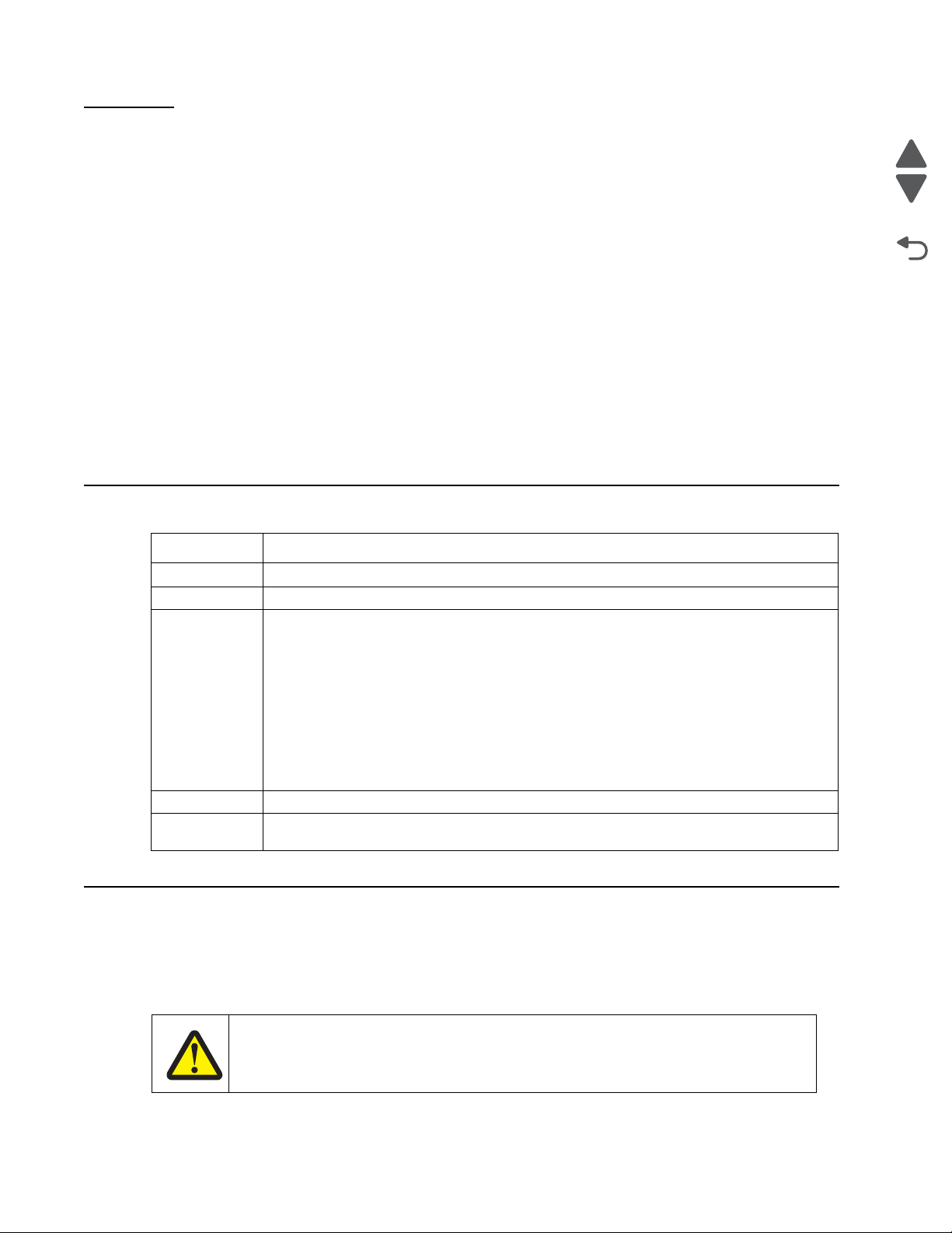
Conventions
Note: A note provides additional information.
Warning: A warning identifies something that might damage the product hardware or software.
There are several types of caution statements:
• Added the “Waste toner HV contact assembly removal” on page 4-176.
• Added the “Contact springs kit removal” on page 4-70 with the following sub
removals:
“Charge roll contact spri ng rem oval” on page 4-70
“HVPS contact springs removal” on page4-71
“Torsion spring removal” on page 4-72, which was formerly contact spring removal
• Updated the “Left” on page 7-11 to add the auger drive and shaft and waste toner HV
contact part numbers.
• Updated the illustration for “Lef t” on pa ge 7-10 to include the auger drive and shaft and
waste toner HV contact.
coincide with the art.
xviii Service Manual
Page 19
5026
Go Back
Previous
Next
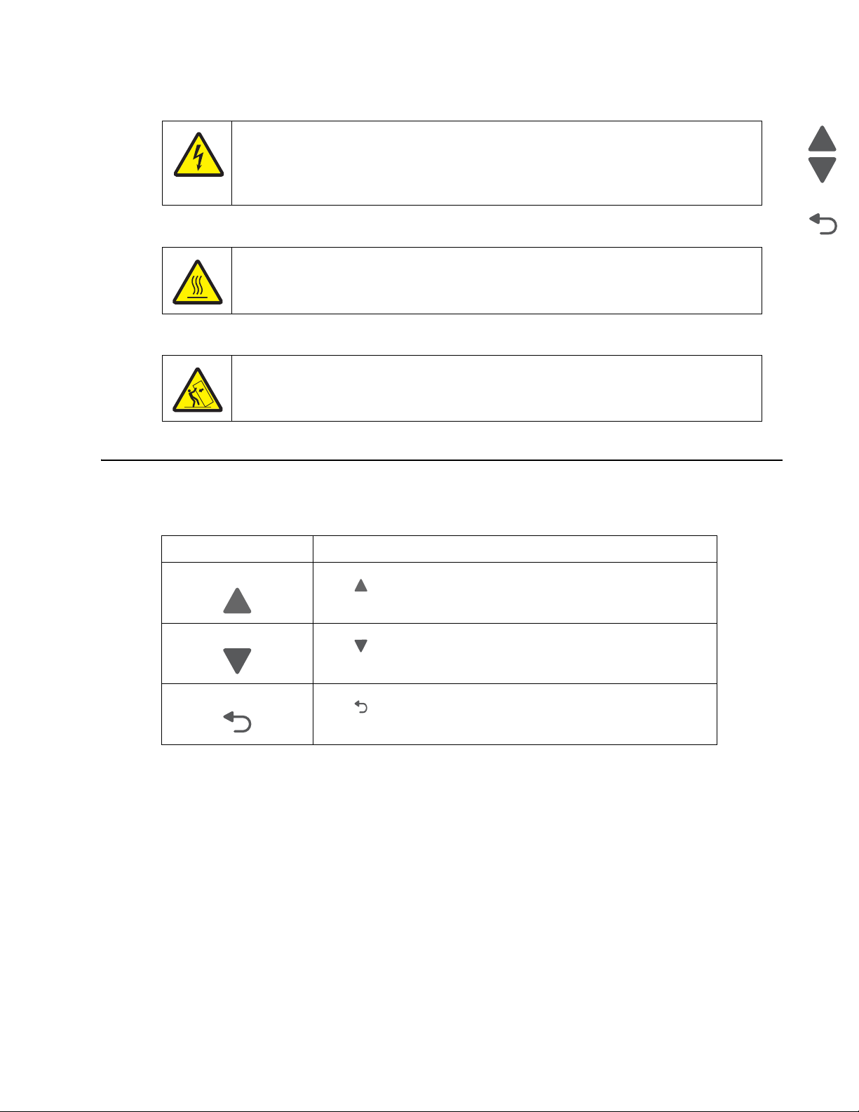
CAUTION
This type of caution indicates there is a danger from hazardous voltage in the area of the
product where you are working. Unplug the product before you begin, or use caution if the
product must receive power in order to perform the task.
CAUTION
This type of caution indicates a hot surface.
CAUTION
This type of caution indicates a tipping hazard.
Navigation buttons
This manual contains navigation buttons in the right margin of each page, making it easier and quicker to navigate.
Button Description
Previous
Click to move the document view backward by one page.
Next
Click to move the document view forward by one page.
Go Back
Click to return to the last page viewed.
Conventions xix
Page 20

5026
Go Back
Previous
Next
xx Service Manual
Page 21
5026
Go Back
Previous
Next
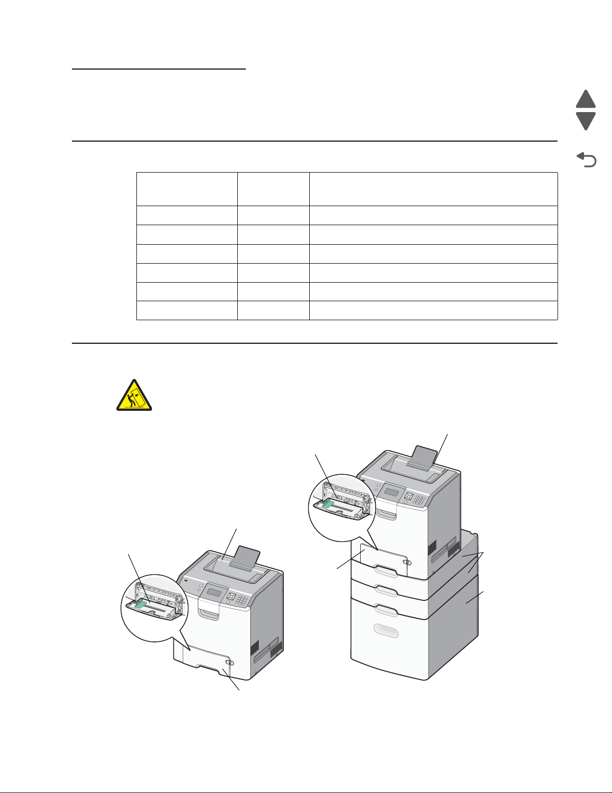
Standard exit bin
Standard exit bin
Multipurpose
feeder
Multipurpose
feeder
Standard 550-sheet
tray (tray 1)
Standard
Optional 550-sheet
trays/special media
550-sheet
(tray 1)
trays
Optional
high-capacity
input tray
(2,000 sheets)
1. General in formation
The Lexmark™ C73x family of color laser printers.
Models
Options
Printer name
Machine type
and model
Description
Lexmark C734n 5026-210 Network
Lexmark C734dn 5026-230 Duplex and network
Lexmark C734dnw 5026-280 Duplex, network, and wireless
Lexmark C736n 5026-410 Network
Lexmark C736dn 5026-430 Duplex and network
Lexmark CS736dn 5026-439 Duplex and network
Note: Some configurations may require a caster base for stability.
General information 1-1
Page 22

5026
Go Back
Previous
Next
Media options
The C734 and C736 printers support the 550-sheet drawer, special media drawers, and 2000-sheet highcapacity input tray. The Lexmark C734 printers support up to three input options, while the C736 printers
support up to four input options. The options can include any combination of 550 sheet drawers and 550 sheet
Specialty Media Drawers, with a maximum of one 2000 sheet drawer (always at the lowest position.) A caster
base is required with some configurations. Including the base machine capacity of 650 sheets, the C734
supports up to 3750 sheets and the C736 supports up to 4300 sheets.
The Lexmark C73x options are compatible with the Lexmark X73x MFP, but not with any other Lexmark printers.
No other options are supported by the C73x.
The media options include:
• 550-Sheet Drawer—This optional input source installs beneath the printer, and it holds approximately 550
sheets of (20 lb.) paper.
• High Capacity Input Tray—This optional input source installs beneath the printer, and it holds
approximately 2000 sheets of (20 lb.) paper.
• Specialty Media Drawer—This optional input source installs beneath the printer, and it holds
approximately 550 sheets of (20 lb.) paper, or 85 standard envelopes.
Memory options
• Additional memory card—The memory options for the C734 and C736 printers are 200 pin DDR2,
SODIMM, and they are available at 256MB, 512MB, and 1GB sizes.
• Flash memory card—Flash Memory cards are available in 256MB.
• Hard disk—If larger storage is required, an optional hard disk is available.
1-2 Service Manual
Page 23
5026
Go Back
Previous
Next
Printer specifications
Dimensions
The following table contains the dimensions and weight for each of the respective printer models. This does not
include packaging.
Height Width Depth Weight
Lexmark C734/C736
Basic printer (cartridges only) 450mm
Printer without toner cartridges,
photoconductors
Lexmark C734dtn/C736dtn
Printer with 550-sheet optional
drawer
Features fully extended
Output paper support extended 527mm
Paper tray extended in back
Letter size media
A4 size media
Legal size media
Fully configured printer with
output paper support extended
Fully configured printer with
output paper support extended
and multipurpose feeder
extended
(17.7 in)
450mm
(17.7 in)
572mm
(22.5 in)
(20.75 in)
450mm
(17.7 in)
450mm
(17.7 in)
450mm
(17.7 in)
525mm
(20.7 in)
525mm
(20.7 in)
435mm
(17.1 in)
435mm
(17.1 in)
435mm
(17.1 in)
435mm
(17.1 in)
435mm
(17.1 in)
435mm
(17.1 in)
435mm
(17.1 in)
435mm
(17.1 in)
435mm
(17.1 in)
400mm
(15.7 in)
400mm
(15.7 in)
545mm
(21.5 in)
391mm
(15.4 in)
470mm
(18.5 in)
488mm
(19.2 in)
527mm
(20.7 in)
400mm
(15.7 in)
584mm
(23.0 in)
25.7kg
(56.7 lbs)
20.0kg
(44.1 lbs)
29.7 kg
(65.5 lbs)
25.7kg
(56.7 lbs)
25.7kg
(56.7 lbs)
25.7kg
(56.7 lbs)
25.7kg
(56.7 lbs)
25.7 kg
(56.7 lbs)
25.7 kg
(56.7 lbs)
Fully configured printer with
550-sheet option tray, output
bin extended, and
multipurpose feeder extended
Options and features
550-sheet drawer only 122mm
High-capacity input tray
(2000-sheet) only
Spacer only 122mm
Caster base only 108 mm
Desktop to bottom of operator
panel
647mm
(25.5 in)
(4.8 in)
345mm
(13.6 in)
(4.8 in)
(4.3 in)
(16 in)
435mm
(17.1 in)
435mm
(17.1 in)
435mm
(17.1 in)
435mm
(17.1 in)
778 mm
(30.6 in)
729mm
(28.7 in)
545mm
(21.5 in)
545mm
(21.5 in)
545mm
(21.5 in)
812 mm
(32.0 in)
29.7 kg
(65.5 lbs)
4.4 kg
(9.7 lbs)
26.1 kg
(57.5 lbs)
3.6 kg
(8.0 lbs)
42.6 kg
(94 lbs)
General information 1-3
Page 24
5026
Go Back
Previous
Next
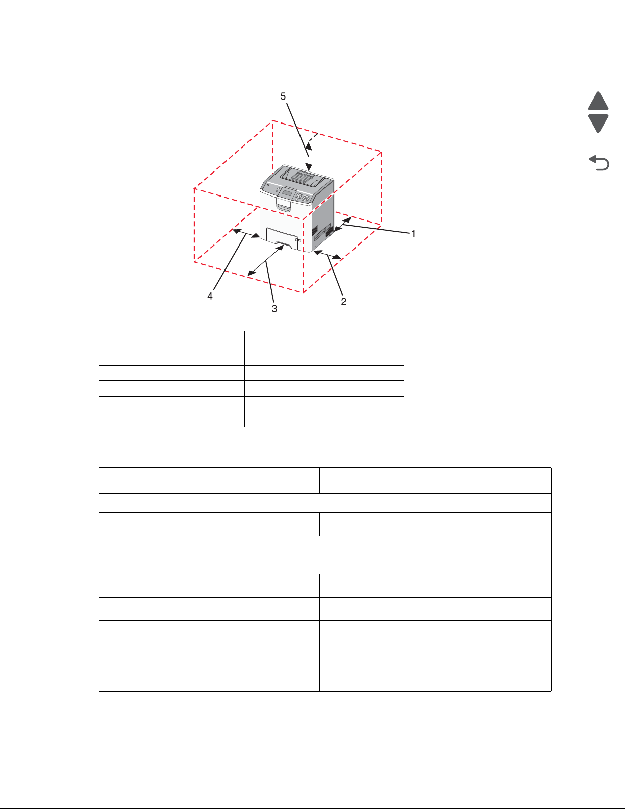
Clearances
Memory
Number Description Clearance
1 Rear 100 mm (3.9 in.)
2 Right side 100 mm (3.9 in.)
3 Front 400 mm (15.7 in.)
4 Left side 150 mm (5.9. in.)
5 Above 150 mm (5.9 in.)
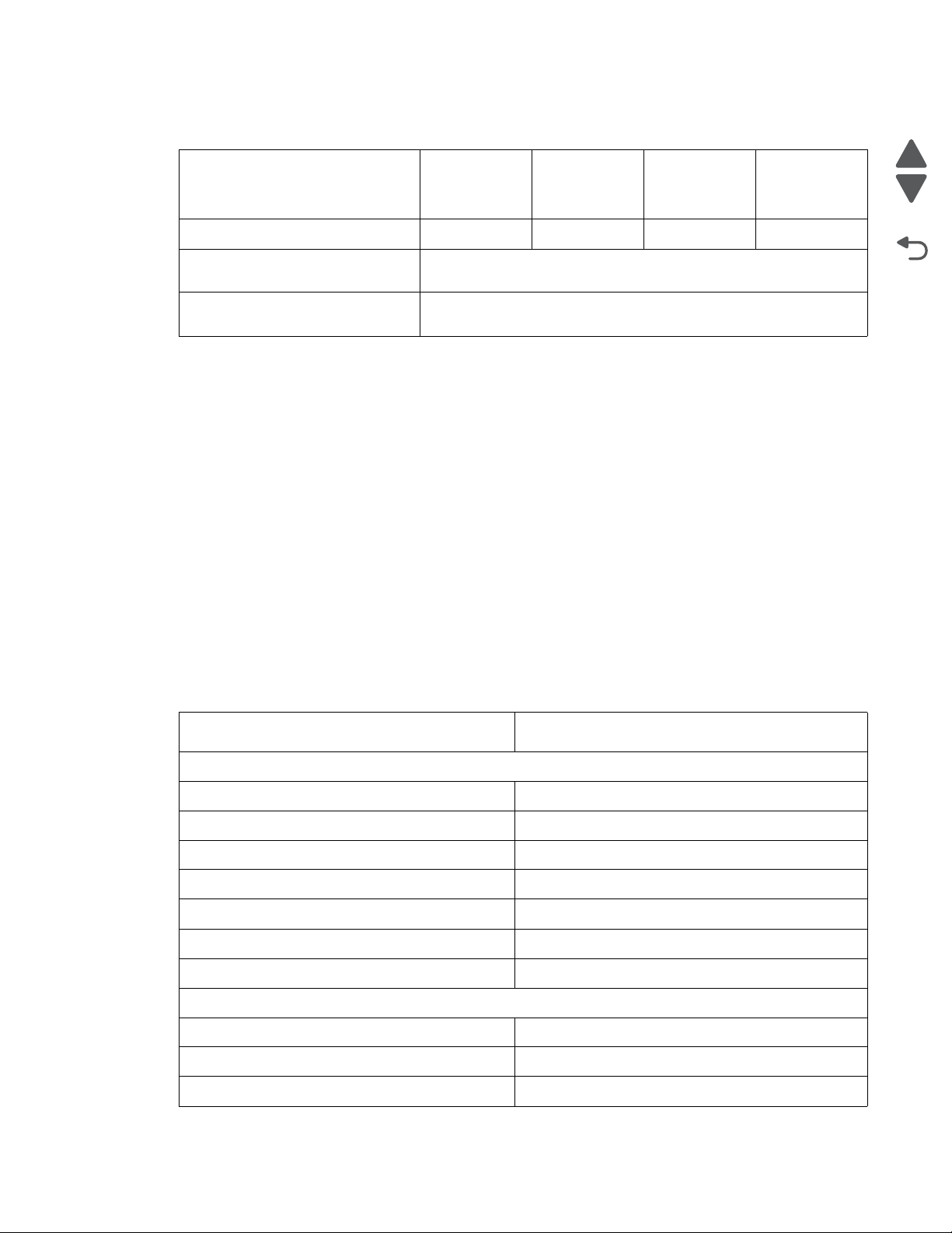
Memory
Standard memory—The standard RAM is soldered onto the system board.
Memory size
Optional memory—Optional DIMM (Dual Inline Memory Module) is a card that can be plugged into an
available memory slot on the system board. Flash memory is a card that can also be plugged into an
available slot.
Maximum number of memory (DIMM) slots
Maximum number of flash memory slots
DIMM memory sizes available
All models
256MB
1
1
256MB, 512MB, 1024MB
Flash (Nand Flash)
Maximum possible memory
1-4 Service Manual
256
1280MB
Page 25
5026
Go Back
Previous
Next
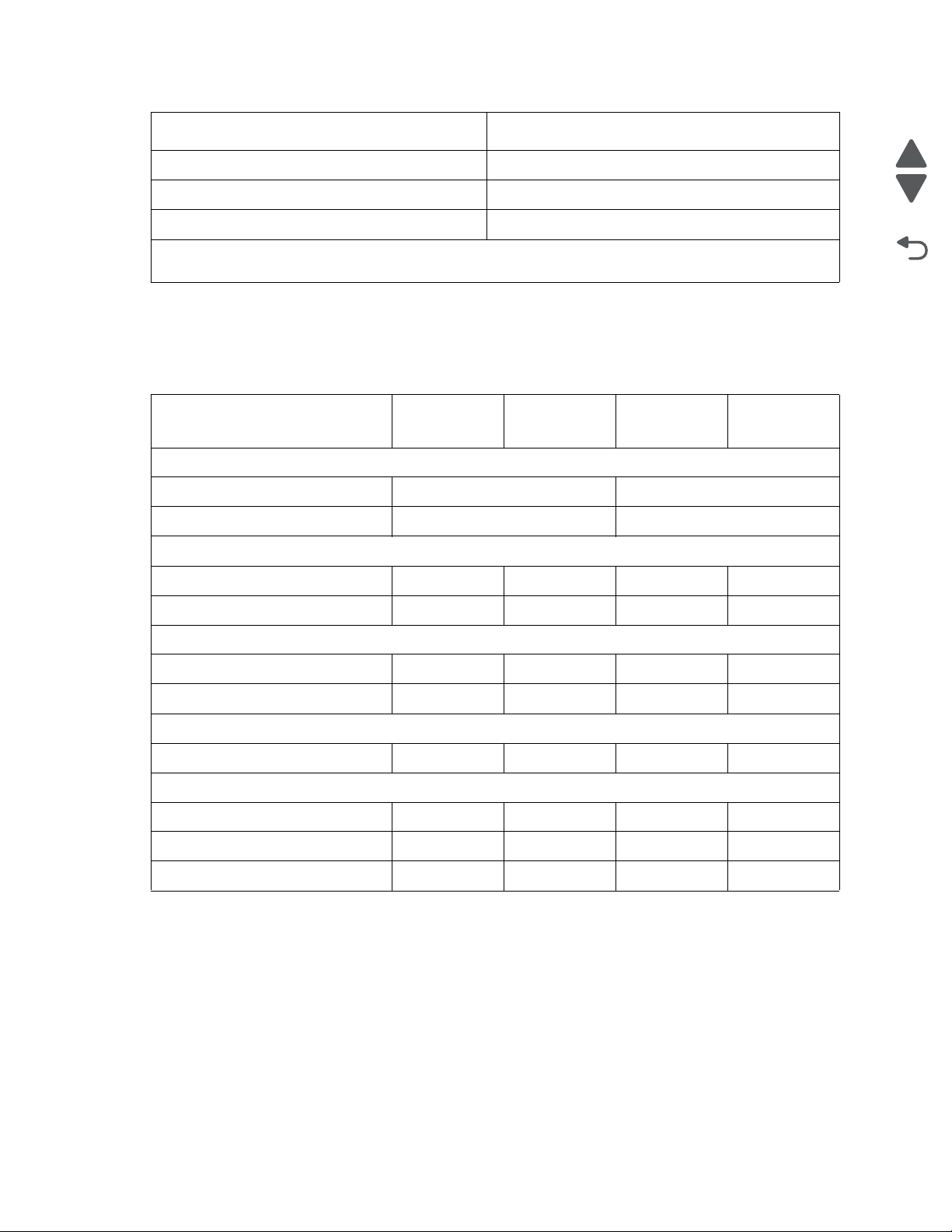
Expansion opportunities
Interface card expansion slots1011
Code Enhancement Socket
(application solution firmware)
Hard disk Interface (for optional
hard disk)
Resolution
The following resolutions are available:
• 4800CQ (default resolution)
• 1200 x 1200 dpi (at reduced printer speed)
Data streams
• PostScript 3 emulation
• PCL 5c and PCL 6 XL Emulations
• PDF 1.6 with backward compatibility
• PPDS (activated from configuration menu)
• HTML
• XPS
• Direct Image (TIFF, TIF, JPEG, JPG, GIF, PNG, BMP, PCX, and DCX)
Lexmark
C734n,
C734dn
Lexmark
C734dw
Lexmark
C736n
1
1
Lexmark
C736dn
Environment specifications
Environment Specifications
Operating
Air temperature—Operating 15.6° to 32.2° C (60° to 90° F)
Air temperature—Power off 10° to 40° C (50° to 104° F)
Air Relative Humidity 8% to 80%
Wet Bulb Temperature—Operating 22.8° C (73.0° F) Maximum
Web Bulb Temperature—Power off 26.7° C (80.1° F) Maximum
Altitude 0–3,048 meters (10,000 ft.)
Ambient Operating Environment* 15.6° to 32.2° C (60° to 90° F) and 8% to 80% RH
Shipping and storage
Cartridges (packaged) -40° C to 40° C (104° Fahrenheit)
Printer with Cartridges (packaged) -40° C to 40° C (104° Fahrenheit)
Printer without Cartridges -40° C to 40° C (104° Fahrenheit)
General information 1-5
Page 26
5026
Go Back
Previous
Next
Environment Specifications
Air Relative Humidity Relative Humidity 8% to 80%
Altitude 0–10,300 meters (34,000 feet)
Web Bulb Temperature—Power Off 26.7° C (80.1° F) Maximum
* In some cases performance specifications, such as paper OCF and EP cartridge usage, are specified to
be measured at an ambient condition.
Electrical and power specifications
The following table specifies nominal average power requirements for the basic printer configurations. All power
levels are shown in Watts (W). Maximum current is given in Amperes (A).
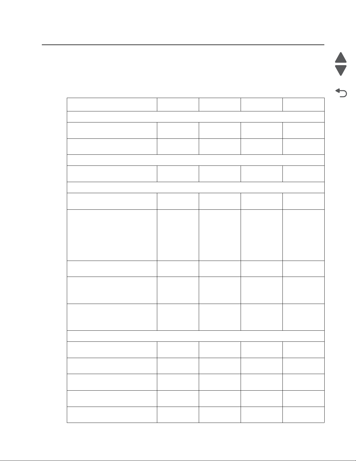
Printing states
Typical Electricity Consumption (TEC)
Normal settings 4.61 kwh/week 4.69 kwh/week
Eco Mode settings 3.83 kwh/week 4.10 kwh/week
Average power while printing
Simplex printing 490 W 490 W 530 W 530 W
Duplex printing N/A 390 W N/A 420 W
Average power while idle
Power Saver 16 W 16 W 16 W 16 W
Ready 45 W 45 W 45 W 45 W
Average power while off
Off 0 W0 W0 W0 W
Maximum average current while printing
220–240 Volts 3.8 A 3.8 A 3.8 A 3.8 A
110–127 Volts 7.5 A 7.5 A 7.5 A 7.5 A
Lexmark
C734n
Lexmark
C734dn/dw
Lexmark
C736n
Lexmark
C736dn
100–110 Volts 8.3 A 8.3 A 8.3 A 8.3 A
Low-voltage models
• 110 to 127 V ac at 47 to 63 Hertz (Hz) nominal
• 99 to 137 V ac, extreme
100-voltage model
• 100 V ac at 47 to 63 Hertz (Hz) nominal
• 90 to 110 V ac, extreme
High-voltage models
• 220 to 240 V ac at 47 to 63 Hz (not available in all countries)
1-6 Service Manual
Page 27
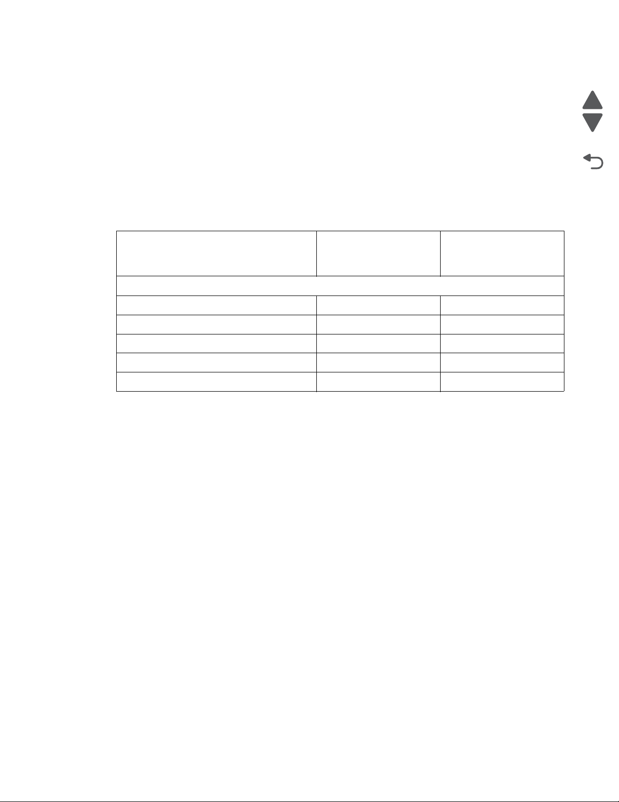
5026
Go Back
Previous
Next
• 198 to 259 V ac, extreme
Notes:
• Using a 220 V ac to 110 V ac power converter with the low-voltage printer is not recommended.
• Using an inverter (12 V dc to 120 V ac for example) to power the printer is not recommended.
• Only duplex models are ENERGY STAR certified.
Acoustic specifications
All acoustic measurements are made in accordance with ISO 7779:1999—Accoustics : Measure ment of air borne
noise emitted by information technology and telecommunications and reported in conformance with ISO 9296:
1988-04-15—Accoustics Declared noise emission values of computer and business equipment.
1-Meter average
Operating mode
Lexmark C734/C736
Mono printing (full speed) 54 dBA
Color printing (full speed) 54 dBA
Duplex printing (full speed) 54 dBA
Quiet Print Mode (reduced speed) 48 dBA
Idle 31 dBA
bystander sound
pressure at 4800 CQ
Declared sound power
level at 4800 CQ
General information 1-7
Page 28

5026
Go Back
Previous
Next
Media specifications
Paper designed for use with xerographic copiers should provide satisfactory print quality and feed reliability.
Other types of media may be suitable. It is recommended that users test any particular brand for suitability to
their applications. Refer to the printer User's Guide for additional media specifications.
Paper
Follow the media guidelines below for successful printing:
• Rough, highly textured, limp, or pre-curled papers will result in lower print quality and more frequent paper
feed failures.
• Colored papers must be able to withstand 190° C (374° F) fusing temperature.
• Preprinted forms and letterheads must be able to withstand 190° C (374° F) fusing temperature and should
be selected using guidelines found in the printer User’s Guide. The chemical process used in preprinting
may render some papers unsuitable for use.
• Unsuitable papers include:
– Multi-part forms and documents
– Chemically treated papers; coated
– Synthetic and thermal papers
– A5 paper less than 80 g/m
– Recycled paper less than 75 g/m
– Preprinted papers requiring a high degree of registration.
– Recycled paper less than 80 g/m
2
(21 lb)
2
(20 lb)
2
(21 lb) may cause unacceptable results.
Envelopes
All envelopes should be new, unused, and without package damage.
•
• Envelopes with excessive curl or twist exceeding 6 mm, those stuck together, those with bent corners or
nicked edges, or those that interlock should not be used.
• Minimum weight: 60 g/m2 (16 lb.)
• The following envelopes should not be used:
• Envelopes with windows, holes, perforations, cutouts, or deep embossing
• Envelopes with metal clasps, string ties, or metal folding bars
• Envelopes with exposed flap adhesive when the flap is in the closed position.
• For best results, printing on new 90 g/m2 (24 lb.) sulfite or 25% cotton bond envelopes is recommended.
• Under high humidity conditions (over 60%), envelopes may seal during printing.
Transparencies
•
Use letter or A4-size transparencies for color laser printers only.
• See Ordering Information for the recommended transparencies for the Lexmark C734/C736 laser printers.
• Do not use inkjet transparencies.
Labels
Labels should be selected using guidelines found in the User's Guide or the Card Stock and Label Guide, and
tested for acceptability.
1-8 Service Manual
Page 29

5026
Go Back
Previous
Next
Using recycled paper and other office papers
Recycled office paper produced specifically for use in laser (electrophotographic) printers may be used in your
printer. However, no blanket statement can be made that all recycled paper will feed well.
Generally, the following property guidelines apply to recycled paper.
• Low moisture content (4–5%)
• Suitable smoothness (100–200 Sheffield units, or 140–350 Bendtsen units, European)
Note: Some much smoother papers (such as premium 24 lb laser papers, 50–90 Sheffield units) and
much rougher papers (such as premium cotton papers, 200–300 Sheffield units) have been engineered to
work very well in laser printers, despite surface texture. Before using these types of paper, consult your
paper supplier.
• Suitable sheet-to-sheet coefficient of friction (0.4–0.6)
• Sufficient bending resistance in the direction of feed
2
Recycled paper, paper of lower weight (<60 g/m
paper that is cut grain-short for portrait (or short-edge) fed printers may have lower bending resistance than is
required for reliable paper feeding. Before using these types of paper for laser (electrophotographic) printing,
consult your paper supplier. Remember that these are general guidelines only and that paper meeting these
guidelines may still cause paper feeding problems in any laser printer (for example, if the paper curls
excessively under normal printing conditions).
[16 lb bond]) and/or lower caliper (<3.8 mils [0.1 mm]), and
General information 1-9
Page 30

5026
Go Back
Previous
Next
Input and output capacities
The following table describes the media options that each model supports, and the estimated capacities in stand
and maximum configurations. Capacity may vary and is subject to media specifications and printer operating
environment. The capacities are based on plain paper at 75g/m
Support by model
Function
Lexmark C734n/dn/dw Lexmark C736n/dn
Standard input sources
Primary tray capacity (sheets) 550 550
Multipurpose feeder capacity (sheets) 100 100
2
.
Number of standard sources (primary tray
22
and multipurpose feeder)
Total standard capacity (sheets) 650 650
Optional input sources
550-Sheet Drawer (sheets) 550 550
High-capacity input tray (HCIT) (sheets) 2,000 2,000
Specialty Media Drawer
Maximum number of 550-sheet drawers
a
(sheets) 550 (or 85 envelopes) 550 (or 85 envelopes)
34
(including Speciality Media Drawer)
Maximum number of high-capacity input
11
tray (must be installed on the bottom)
Maximum number of standard and
56
optional input sources
Maximum capacity for standard and
3,750 4,300
options input sources (sheets)
b
Standard output bin capacity (sheets)
300 300
Maximum output bin capacity (sheets) 300 300
Duplex capability Standard for C734dn and
C74dw models
a
Each 550-sheet Specialty Media Drawer replaces one 550-sheet option.
b
The output bin capacity may be reduced by 50 sheets when the duplex feature is in use.
C734dn model
Standard for
1-10 Service Manual
Page 31
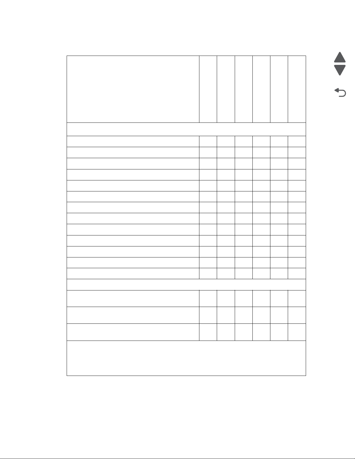
5026
Go Back
Previous
Next
Input and output sizes and types
Media Sizes
Primary 550-sheet tray
Multipurpose feeder
Optional 550-sheet tray
Optional Speciality
Media
Optional 2000-sheet
feeder (HCIT)
Duplex
Paper sizes
A4 210 x 297 mm ✓✓✓✓✓✓
A5 148 x 210 mm ✓✓✓✓ ✓
A6 105 x 148 mm ✓✓
a
ISO B5 176 x 250 mm
✓✓✓✓ ✓
JIS B5 182 x 257 mm ✓✓✓✓ ✓
Officio (Mexico) 216 x 340 mm ✓✓✓✓ ✓
Letter 8.5 x 11 in. ✓✓✓✓✓✓
Legal 8.5 x 14 in. ✓✓✓✓✓✓
1
3 x 5
✓✓
1
✓✓
4 x 5
Statement 5.5 x 8.5 in. ✓✓✓
Executive 7.25 x 10.5 in. ✓✓✓✓ ✓
Folio 8.5 x 13 in. ✓✓✓✓ ✓
Universal
b
(width x Length)
• 76.2 x 123.8 mm (3 x 4.9 in) to
✓✓
215.9 (8.5 x 14 in.)
• 148 x 210 mm (5.8 x 8.3 in) to
✓✓✓✓ ✓
215.8 x 355.6 mm (8.5 x 48 in.)
• 76.2 x 123.8 mm (3 x 4.9 in) to
215.9 x 1219 mm (8.5 x 48 in.)
a
These sizes are accessible using Universal Size setting.
b
Lower feed reliability may be encountered when feeding non-standard size media.
c
The maximum length supported by the Lexmark C734 is 914.4mm (36 in).
d
These sizes are accessible using Other Envelope setting.
c
✓
General information 1-11
Page 32

5026
Go Back
Previous
Next
Media Sizes (continued)
Primary 550-sheet tray
Multipurpose feeder
Optional 550-sheet tray
Optional Speciality
Media
Envelopes
C6 Envelope 114 x 162 mm
B6 Envelope 125 x 176 mm
C65 Envelope 114 x 229 mm
d
d
d
✓✓
✓✓
✓✓
C5 Envelope 162 x 229 mm ✓✓
B5 Envelope 176 x 250 mm ✓✓
DL Envelope 110 x 220 mm ✓✓
6 3/4 Envelope 3.4 x 6.5 in
7 3/4
Envelope 3.4 x 7.5
9 Envelope 3.9
10 Envelope 4.13
x 8.9 in ✓✓
x 9.5 in ✓✓
11 Envelope 4.5 x 10.4 in
12 Envelope 4.8 x 11 in
a
These sizes are accessible using Universal Size setting.
b
Lower feed reliability may be encountered when feeding non-standard size media.
c
The maximum length supported by the Lexmark C734 is 914.4mm (36 in).
d
These sizes are accessible using Other Envelope setting.
d
✓✓
in ✓✓
d
✓✓
d
✓✓
Optional 2000-sheet
feeder (HCIT)
Duplex
1-12 Service Manual
Page 33

5026
Go Back
Previous
Next
Media weight, primary tray and opt ion tray
Size Type Weight
Letter, Legal, A4 Xerographic and bond Long grain 60 g/m
Short grain 162.7 g/m
Recycled Long grain 75 g/m
Short grain 105 g/m
Cardstock (maximum) Index long/short 162.7 g/m
Cover long/short 162.7g/m
Tag long/short 162.7g/m
Transparencies 161 g/m
2
–162.7 g/m2 (16 lb–43 lb)
2
–198.9 g/m2 (43 lb–53.2 lb)
2
–177 g/m2 (20 lb–47 lb)
2
–218 g/m2 (28 lb–58 lb)
2
–198.9 g/m2 (90 lb–110 lb)
2
–198.9 g/m2 (60.1 lb–73.6 lb)
2
–198.9 g/m2 (100 lb–122.2 lb)
2
– 179 g/m
2
Thickness: 0.12–0.14mm (4.8–5.4 mil)
Labels Paper 180 g/m
Vinyl 180 g/m
A5, JIS B5, Executive Xerographic and bond Long grain 75 g/m
Short grain 90 g/m
Universal Xerographic and bond Long grain 75 g/m
Short grain 90 g/m
2
–300 g/m2 (48 lb–80 lb)
2
–300 g/m2 (48 lb–80 lb)
2
–177 g/m2 (20 lb to 47 lb)
2
–218 g/m2 (24 lb–58 lb)
2
–177 g/m2 (20 lb–47 lb)
2
–218 g/m2 (24 lb–58 lb)
Paper guidelines
Paper characteristics
The following paper characteristics affect print quality and reliability. Consider these characteristics when
evaluating new paper stock.
Weight—The printer can automatically feed paper weights from 60 to 162l7 g/m
Paper lighter than 60 g/m
performance, use 75 g/m
we recommend 90 g/m
Note: Duplex is supported only for 63 g/m
Curl—Curl is the tendency for paper to curl at its edges. Excessive curl can cause paper feeding problems. Curl
can occur after the paper passes through the printer, where it is exposed to high temperatures. Storing paper
unwrapped in hot, humid, cold, or dry conditions, even in the trays, can contribute to paper curling prior to
printing and can cause feeding problems.
Smoothness—Paper smoothness directly affects print quality. If paper is too rough, toner cannot fuse to it
properly. If paper is too smooth, it can cause paper feeding or print quality issues. Always use paper between
100 and 300 Sheffield points; however, smoothness between 150 and 200 Sheffield points produces the best
print quality.
Moisture content—The amount of moisture in paper affects both print quality and the ability of the printer to
feed the paper correctly. Leave paper in its original wrapper until it is time to use it. This limits the exposure of
paper to moisture changes that can degrade its performance.
2
2
(16 lb) might not be stiff enough to feed properly, causing jams. For best
2
(20 lb bond) grain long paper. For paper smaller than 182 x 257 mm (7.2 x 10.1 in.),
2
(24 lb) or heavier paper.
2
–170 g/m2 (17 lb–45 lb bond) paper.
(16 to 43 lb bond) grain long.
Condition paper before printing by storing it in its original wrapper in the same environment as the printer for 24
to 48 hours before printing. Extend the time several days if the storage or transportation environment is very
different from the printer environment. Thick paper may also require a longer conditioning period.
General information 1-13
Page 34

5026
Go Back
Previous
Next
Grain directio n—Grain refers to the alignment of the paper fibers in a sheet of paper. Grain is either grain long,
running the length of the paper, or grain short, running the width of the paper. For 60 to 135 g/m
bond) paper, grain long paper is recommended. For papers heavier than 135 g/m
Fiber content—Most high-quality xerographic paper is made from 100% chemically treated pulped wood. This
content provides the paper with a high degree of stability resulting in fewer paper feeding problems and better
print quality. Paper containing fibers such as cotton can negatively affect paper handling.
2
, grain short is recommended.
2
(16 to 36 lb
Unacce p tab l e p aper
The following paper types are not recommended for use with the printer:
• Chemically treated papers used to make copies without carbon paper, also known as carbonless papers,
carbonless copy paper (CCP), or no carbon required (NCR) paper
• Preprinted papers with chemicals that may contaminate the printer
• Preprinted papers that can be affected by the temperature in the printer fuser
• Preprinted papers that require a registration (the precise print location on the page) greater than ±2.3 mm
(±0.9 in.), such as optical character recognition (OCR) forms
Note: In some cases, registration can be adjusted with a software application to successfully print on
these forms.
• Coated papers (erasable bond), synthetic papers, thermal papers
• Rough-edged, rough or heavily textured surface papers, or curled papers
• Recycled papers that fail EN12281:2002 (European)
• Paper weighing less than 60 g/m
2
(16 lb)
• Multiple-part forms or documents
Selecting paper
Using appropriate paper prevents jams and helps ensure trouble-free printing.
To help avoid jams and poor print quality:
• Always use new, undamaged paper.
• Before loading paper, know the recommended print side of the paper. This information is usually indicated
on the paper package.
• Do not use paper that has been cut or trimmed by hand.
• Do not mix paper sizes, types, or weights in the same source; mixing results in jams.
• Do not use coated papers unless they are specifically designed for electrophotographic printing.
Selecting preprinted forms and letterhead
Use these guidelines when selecting preprinted forms and letterhead:
• Use grain long for 60 to 90 g/m
2
(16 to 20 lb) weight paper.
• Use only forms and letterhead printed using an offset lithographic or engraved printing process.
• Avoid papers with rough or heavily textured surfaces.
Use papers printed with heat-resistant inks designed for use in xerographic copiers. The ink must be able to
withstand temperatures up to 190°C (374°F) without melting or releasing hazardous emissions. Use inks that
are not affected by the resin in toner. Inks that are oxidation-set or oil-based generally meet these requirements;
latex inks might not. When in doubt, contact the paper supplier.
Preprinted papers such as letterhead must be able to withstand temperatures up to 190°C (374°F) without
melting or releasing hazardous emissions.
1-14 Service Manual
Page 35

5026
Go Back
Previous
Next
Storing paper
Use these paper storage guidelines to help avoid jams and uneven print quality:
• For best results, store paper where the temperature is 21°C (70°F) and the relative humidity is 40%. Most
label manufacturers recommend printing in a temperature range of 18 to 24°C (65 to 75°F) with relative
humidity between 40 and 60%.
• Store paper in cartons when possible, on a pallet or shelf, rather than on the floor.
• Store individual packages on a flat surface.
• Do not store anything on top of individual paper packages.
Tools required for service
Flat-blade screwdrivers, various sizes
#1 Phillips screwdriver, magnetic
#2 Phillips screwdriver, magnetic
#2 Phillips screwdriver, magnetic short-blade
7/32 inch (5.5 mm) open-end wrench
4.0 mm Allen wrench (HCIT removal)
7.0 mm nut driver
Needlenose pliers
Diagonal side cutters
Spring hook
Feeler gauges
Analog or digital multimeter
Parallel wrap plug 1319128
Twinax/serial debug cable 1381963
Coax/serial debug cable 1381964
Flash light (optional)
Acronyms
Delete any unused terms and add any terms that appear in your book.
BLDC Brushless DC Motor
BUR Back Up Roll
CCyan
COD Color On Demand
DIMM Dual Inline Memory Module
DRAM Dynamic Random Access Memory
EP Electrophotographic Process
ESD Electrostatic Discharge
FRU Field Replaceable Unit
GB Gigabyte
HCIT High-Capacity Input Tray
HVPS High Voltage Power Supply
KBlack
LASER Light Amplification by Stimulated Emission of Radiation
LCD Liquid Crystal Display
LED Light-Emitting Diode
LVPS Low-Voltage Power Supply
M Magenta
General information 1-15
Page 36

5026
Go Back
Previous
Next
MPF Multipurpose Feeder
NVRAM Nonvolatile Random Access Memory
PC Photoconductor
pel Picture element (pixel)
POR Power-On Reset
POST Power-On Self Test
RIP Raster Imaging Processor
SDRAM Synchronous Dual Random Access Memory
V ac Volts alternating current
V dc Volts direct current
YYellow
1-16 Service Manual
Page 37

5026
Go Back
Previous
Next
CAUTION
Remove the power cord from the electrical outlet before you connect or disconnect any cable
or electronic card or assembly for personal safety and to prevent damage to the printer.
CAUTION
Use the handholds on the side of the printer. Make sure your fingers are not under the printer
when you lift or set the printer down.
2. Diagnostic information
Start
Use the service error code, user status message, user error message, symptom table, service checks, and
diagnostic aids in this chapter to determine the corrective action necessary to repair a malfunctioning printer.
They will lead you to solutions or service checks, including use of various tests.
Sympto m tables
If your printer completes the “Power-on self test ( P OST ) sequence” on page 2-4 without an error, and you
have a symptom, go to “Symptom tables” on page 2-5. Locate your symptom, and take the appropriate action.
Servi ce erro r s (1xx.x x/9xx.xx)
If a service error code appears while you are working on the printer, go to “1xx service error codes” on
page 2-16 or “9xx service error messages” on page2-30, and take the indicated action for that error.
Service error codes are indicated by a three-digit error code followed by a period and additional numbers in the
format XXX.YY. In most cases, five digits are shown.
Paper j am message s (2xx.x x)
User attendance messages that indicate a paper jam have been included with the service error codes since
repeated instances may indicate an underlying service issue. Go to “2xx paper jam messages” on page 2-18.
User status and attendance messages
User status messages provide the user with information on the current status of the printer.
•
• User attendance messages are indicated by a two-digit code that provides the user with information that
explains a problem with a print cartridge, option, port, and so on. If a user error message displays, see “3x
through 8x attendance messages” on page 2-8 or “2xx paper jam messages” on page2-18.
Additional information
•
“Operator panel and menus” on page 2-2
• “Power-on self test (POST) sequence” on page 2-4
Diagnostic information 2-1
Page 38

5026
Go Back
Previous
Next
Display Select Navigation arrow
Numeric
keypad
Back buttonIndicator light
Cancel/
Stop
Menu button
USB direct
port
button buttons
Indicator light
status
Indicates
Off Printer power is off.
Blinking green Printer is warming up, processing data, or
printing a job.
Solid green Printer is on, but idle.
Solid red Operator intervention is required.
Operator pan el an d me nu s
Operator panel
Buttons and light description
Button or light Function
Display The display shows messages and pictures that communicate the status of the
Select The button functions as a select button. Press this button to:
Navigation arrow buttons , —Press these buttons to scroll up or down through menus, menu items, or
Indicator light The two-toned light emitting diode called the indicator light on the operator panel
printer.
• Open a menu and display the first item in the menu (called a menu item).
• Open a menu item and display the default setting.
• Save the displayed menu item as the new user default setting. The printer
issues a Saved or Submitted Selection message and returns to the menu item.
Note: When a new setting is saved as the user default setting, it remains in effect
until new settings are saved or until factory defaults are restored. Settings chosen
from the software application can also change or override the user default settings
selected from the operator panel.
settings, called menu item values, or to scroll between screens and menu values.
Each press moves one item in the list or a different setting for a menu item.
, —Press these buttons to scroll items that wrap off of the screen. For menu
items with numeric values, such as Copies, press and hold this button to scroll
through the values. Release the button when the needed number appears.
gives information about the status of the printer using the colors red and green.
2-2 Service Manual
Stop Press to stop or suspend all job activity. The functions as a stop button.
If printing, pressing causes the Stop screen to appear on the display.
Menu Press to open the administration menus. These menus are only available when the
printer is in the Ready state.
Page 39
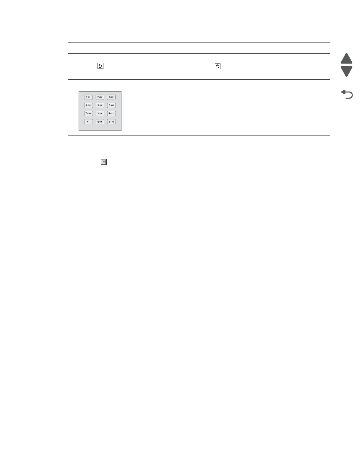
5026
Go Back
Previous
Next
Supplies Menu Paper Menu Reports Settings
Replace Supply Default Source Menu Settings Page General Settings
Cyan Cartridge Paper Size/Type Device Statistics Setup Menu
Magenta Cartridge Configure MP Network Setup Page Finishing Menu
Yellow Cartridge Substitute Size Network <x> Setup Page Quality Menu
Black Cartridge Paper Texture Wireless Setup Page Utilities Menu
Cyan PC Unit Paper Weight Profiles List XPS Menu
Magenta PC Unit Paper Loading NetWare Setup Page PDF Menu
Yellow PC Unit Custom Types Print Fonts PostScript Menu
Black PC Unit Universal Setup Print Directory PCL Emul Menu
Waste Toner Box Print Demo PPDS Menu
Fuser Asset Report HTML Menu
Transfer Module Image Menu
PictBridge Menu
Flash Drive Menu
Security Network/Ports Help
Miscellaneous Security Setting Active NIC Print All
Confidential Print Standard Network* Color Quality
Disk Wiping Standard USB Print Quality
Security Audit Log Standard Network Printing Guide
Set Date/Time Parallel <x> Media Guide
Serial <x> Print Defects
SMPT Setup Menu Map
Information Guide
Connection Guide
Moving Guide
Supplies Guide
* Depending on the printer setup, this menu item appears as Standard Network, Wireless Network,
or Network <x>.
Button or light Function
Back Press to return to the previous screen.
Note: This button is only active if appears on the top left of the screen.
USB direct port Insert a USB flash drive to send data to the printer.
Numeric keypad Consists of the numbers 0–9, a backspace button, and a pound (#) button.
Administrative menus
Press Menu ( ) to enter the Administrative menus.
Note: Some menu items may not be available based on the printer model or the options installed.
Diagnostic information 2-3
Page 40

5026
Go Back
Previous
Next
Power-on self test (POST) sequence
When you turn the printer on, it performs a Power-On Self Test. Check for correct POST functioning of the base
printer by observing the following:
1. The LED turns on.
2. The main fan turns on.
3. The operator panel turns on.
4. A partial row of pixels appears.
5. The operator panel display clears.
6. Another row of pixels appears.
7. The operator panel display clears again.
8. The operator panel displays system information. For example:
*256MB 600Mhz
9. The fuser heater turns on. The fuser takes longer to warm up from a cold start than a warm start.
10. The operator panel LED starts blinking.
11. A clock face appears on the display.
The following errors or messages may appear:
• Close Door or Insert Cartridge display if the upper front cover is open or the print cartridge is
missing.
• Any cartridge errors, such as Defective Cartridge or Missing Cartridge.
12. Ready appears on the display.
13. The main drive motor turns on.
14. The EP drive assembly drives the developer shaft located in the toner cartridge.
15. The exit rollers turn.
16. The printer may begin calibration.
2-4 Service Manual
Page 41
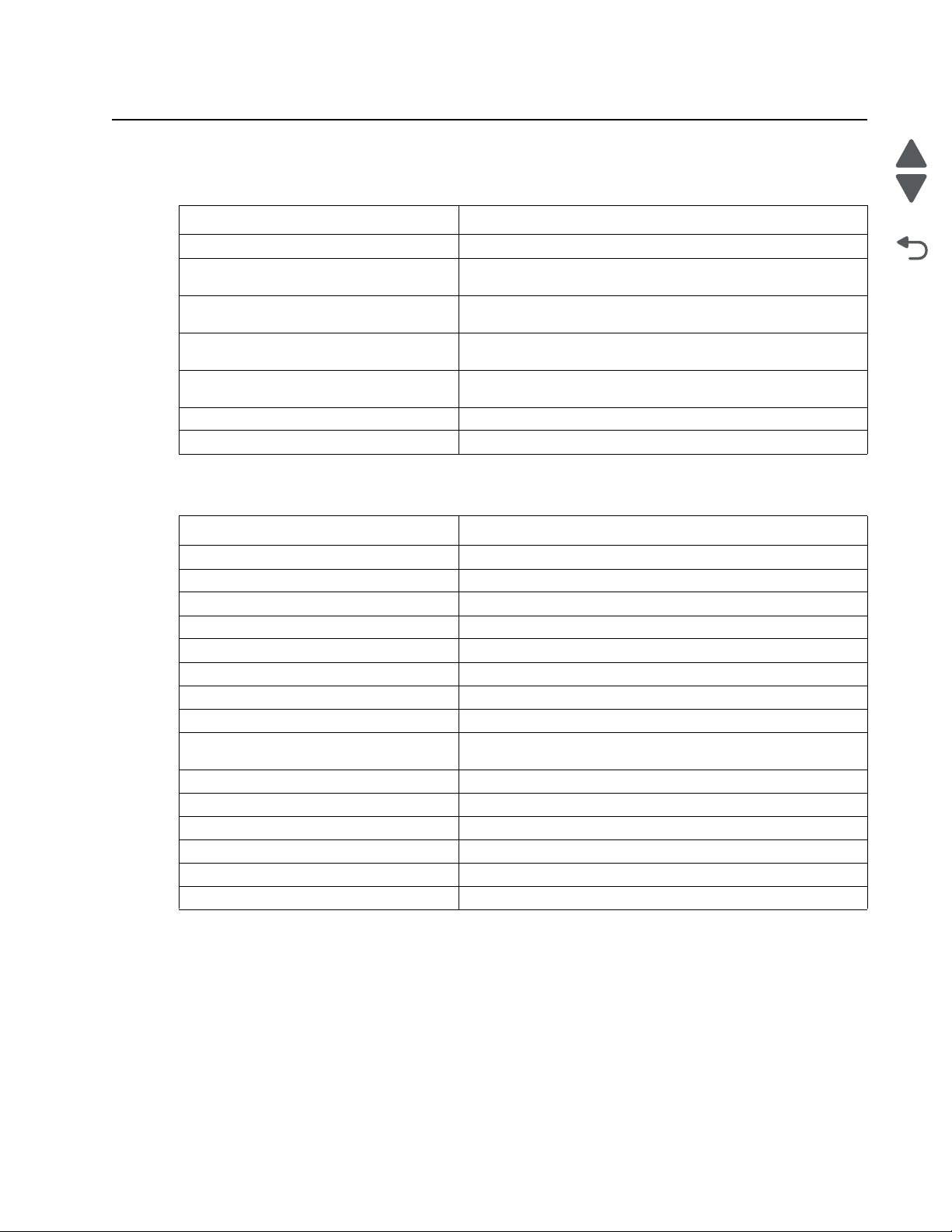
5026
Go Back
Previous
Next
Sympto m tab l e s
Printer symptom table
Symptom Action
Dead printer Go to “Dead printer service check” on page2-126.
Operator panel—one or more buttons do
not work.
Operator panel—display is blank. Printer
sounds five beeps.
Operator panel—display is blank. Go to “Operator panel di splay bl ank, fi ve beeps, LED on ” on
Operator panel continuously displays all
diamonds and does not complete POST.
Tray linking will not work. Go to “Tray linking service check” on page 2-140.
Front cover locks, and will not open Go to “Front cover locked in place.
Print quality sympto m table
Go to “One or more operator panel buttons fail” on
page 2-131.
Go to “Operator panel dis play blank, five beeps, and LED is
off” on page 2-131 .
page 2-131.
Go to “Opera tor panel display all diamonds , no beeps” on
page 2-132.
Symptom Action
Background Go to “Print quality—background” on page 2-133.
Blank page Go to “Print qual ity—blank page” on page 2-134.
Blurred or fuzzy print Go to “Print quality—bl urred or fuzzy print” on page 2-136.
Half-color page Go to “Print quality—half-color page” on page 2-136.
Horizontal banding Go to “Print quality—horizo ntal banding” on page 2-136.
Horizontal line Go to “Print quality—horizontal line” on page2-136.
Insufficient fusing Go to “Pri nt quality—insuffi cient fusing” on page 2-136.
Missing image at edge Go to “Print quality—missing image at edge” on page 2-136.
Mottle (2–5mm speckles) Go to “Print quality—mottle (2–5mm speckles)” on
Narrow vertical line Go to “Print quality—narrow vertical line” on page 2-136.
Random marks Go to “Print quality—random mar ks” on page 2-137.
Residual image Go to “Print quality—residual image” on page 2-137.
Solid color page Go to “Print quality—solid color page” on page 2-138.
Vertical banding Go to “Print quality—ver tical banding” on page 2-139.
White gapping Go to “Print quality—whi te gapping” on page 2-139.
page 2-136.
Diagnostic information 2-5
Page 42

5026
Go Back
Previous
Next
User status and attendance messages
Error code Action
Close Front Door Close the front door securely. If you continuously get this error, then either the 24 V interlock
Disk Corrupted,
Reformat?
Held Jobs May Not Be
Restored
Insert Tray <x> Insert tray to clear the message.
Load <source>
<custom type name>
Load <source>
<Custom String>
Load <source> <size> Load paper in the indicated source and of the indicated size, and select Continue.
switch or the 5 V interlock switch is bad. See “24 V interlock switch service check” on
page 2-123 and “5 V interlock switch service check” on page 2-121.
The printer has attempted a disk recovery and cannot repair the disk. The disk must be
formatted to use.
Warning: All files stored on the disk will be lost.
The printer has attempted to restore Held jobs, but not all were restored.
Load paper in the indicated source and of the indicated type. Additional messages may
include:
• Paper loaded—Select Continue.
• Show Me—the printer will present instructions.
• Cancel Job—the printer job can be canceled.
• Wait for supplies—If job parking is enabled, and the job meets all the requirements for
allowing the job to be parted, the printer adds this message.
Load paper in the indicated source, and select Continue.
Additional messages may include:
• Show Me—the printer will present instructions.
• Cancel Job—the printer job can be cancelled.
• Wait for supplies—If job parking is enabled, and the job meets all the requirements for
allowing the job to be parted, the printer adds this message.
Additional messages may include:
• Show Me—the printer will present instructions.
• Cancel Job—the printer job can be cancelled.
• Wait for supplies—If job parking is enabled, and the job meets all the requirements for
allowing the job to be parted, the printer adds this message.
Load Manual <custom
type name>
Load Manual
<custom string>
Load Manual <size> If paper loaded is in the manual feeder, the job continues. If paper is not in the feeder,
If paper loaded is in the manual feeder, the job continues. If paper is not in the feeder,
pressing Select indicates to the printer it should search for a source with the proper custom
type.
Additional messages may include:
• Show Me—the printer will present instructions.
• Cancel Job—the printer job can be cancelled.
If paper loaded is in the manual feeder, the job continues. If paper is not in the feeder,
pressing Select indicates to the printer it should search for a source with the proper custom
string.
Additional messages may include:
• Show Me—the printer will present instructions.
• Cancel Job—the printer job can be cancelled.
pressing Select indicates to the printer it should search for a source with the proper size.
Additional messages may include:
• Show Me—the printer will present instructions.
• Cancel Job—the printer job can be cancelled.
2-6 Service Manual
Page 43

5026
Go Back
Previous
Next
Error code Action
Load Manual <type>
<size>
Paper Changes Needed
PC Unit Exposure
Warning
Remove All Color
Supplies
Remove Paper
Standard Bin
Remove Packaging
Material
Restore Held Jobs
Go/Stop?
If paper loaded is in the manual feeder, the job continues. If paper is not in the feeder,
pressing Select indicates to the printer it should search for a source with the proper type and
size.
Additional messages may include:
• Show Me—the printer will present instructions.
• Cancel Job—the printer job can be cancelled.
This warning occurs when the front door is left open too long. Close the front door to prevent
damage to the PC unit. Select Tell me more for further information.
If Color Lockout mode is enabled, this message appears (unless the printer is in Diagnostics
Menu or Configuration Menu).
The standard output bin is full. Remove the media to continue.
If packaging material is detected by the printer, Check all areas, Check <area name>, or
Check <number of> areas may appear. Press Select to continue.
If the printer detects Print and Hold (or parked) jobs stored on the hard disk during Power-On
Self Test (POST). Choices are:
• Restore—Print jobs are restored, and Restoring Held Jobs x/y, where x is the number
of the job restored and y is the total number of jobs to restore. You can quit restoring, and
the remainder of the jobs will remain on the disk, but cannot be accessed until they are
restored at the next POR.
• Do not restore—Held jobs will remain on the disk, but cannot be accessed until they are
restored at the next POR. Held jobs may not be restored appears.
• Tell me more—additional information is available
Securely Clearing Disk
Space
Tray Length Guide
Disk wiping process is recovering disk space. The message clears when all memory blocks
are cleared.
Replace the tray length guide.
Missing
Unsupported USB
Remove the unrecognized device to continue.
device, Please Remove
Unsupported USB hub,
Remove the unrecognized device to continue.
Please Remove
Unsupported Mode Unplug camera and change it to a mode where the camera can access PictBridge. Plug the
camera back in to continue.
Unsupported Disk Remove the unsupported disk to continue.
Diagnostic information 2-7
Page 44

5026
Go Back
Previous
Next
A
Error code Action
3x through 8x attendance messages
31 Defective or Missing
<color> Cartridge
32 Unsupported
Cartridge
• Reseat the specified toner cartridge.
• Inspect the smart chip card contacts (A) for damage, contamination or positioning error. If
damaged, contact your next level of service.
• Inspect the toner cartridge contacts for damage/contamination. Replace the toner
cartridge if defective.
• Inspect the JSBTN1 cable connection. Properly connect the cable if not connected
properly. Replace the cable if damaged.
• Replace the indicated cartridge.
• If the problem still exists, replace the system board. See “System board remo val” on
page 4-153.
• Check to see if the toner cartridge is a supported cartridge.
Note: Once the cartridge shipped with the printer is exhausted, it must be replaced by a
supply cartridge (refer to the User’s Guide for part numbers.)
If the specified toner cartridge is a supported cartridge, reseat the cartridge.
• Inspect the toner cartridge contacts for damage or contamination. Replace the toner
cartridge if defective.
• Inspect JSBTN1 cable connection. Properly connect the cable if not connected properly.
Replace the cable if damaged.
• If the problem still exists, replace the system board. See “System board remo val” on
page 4-153.
34 Short Paper • Select Continue to clear the message and continue printing.
Note: The printer does not automatically reprint the page that prompted the message.
• Check the tray length and width guides to ensure the media is properly fitted.
• Make sure the print job is requesting the correct size of media.
• Adjust the Paper Size setting for the media size being used.
• If the MP Feeder Size is set to Universal, make sure the media is large enough for the
formatted data.
• Cancel the current job. Replace the paper pick mechanism. See “Paper pick
mechanism assembly removal” on page 4-127.
• If the problem still exists, replace the system board. See “System board remo val” on
page 4-153.
35 Insufficient memory
to support Resource
Save feature
• Select Continue to disable Resource Save and continue printing.
• To enable Resource Save after receiving this message:
- Make sure the link buffers are set to Auto, then exit the menus to activate the link
buffer changes.
- When Ready is displayed, enable Resource Save.
• Install additional memory.
• If this does not fix the problem, replace the system board. See “System board rem oval”
on page 4-153.
2-8 Service Manual
Page 45

5026
Go Back
Previous
Next
Error code Action
37 Insufficient memory
to collate job
37 Insufficient memory
for Flash Memory
Defragment operation
37 Insufficient memory,
Some Held Jobs Were
Not Restored
37 Insufficient memory,
Some Held Jobs Will
Not Be Restored
37 Insufficient Defrag
Memory
• Select Continue to print the portion of the job already stored and begin collating the rest
of the job.
• Cancel the current job.
• If this does not fix the problem, replace the system board. See “System board removal ”
on page 4-153.
• Select Continue to stop the defragment operation and continue printing.
• Delete fonts, macros, and other data in printer memory.
• Install additional printer memory.
• If this does not fix the problem, replace the system. See “System board removal” on
page 4-153.
• The printer deleted some held jobs in order to process current jobs.
• Select Continue to clear the message.
• If this does not fix the problem, replace the system board. See “System board removal ”
on page 4-153.
• The printer was unable to restore some or all of the confidential or held jobs on the hard
disk.
• Select Continue to clear the message.
• If this message occurs again, replace the hard drive.
• If this does not fix the problem, replace the system board. See “System board removal ”
on page 4-153.
There is insufficient memory to perform the Flash Memory Defragment operation. The user
can:
• Delete font, macros, and other data in memory.
• Install additional printer memory.
38 Memory Full The following options are available:
• Select Continue to clear the message and continue printing. The job may not print
correctly.
• Cancel the current job.
• Install additional printer memory.
• If this does not fix the problem, replace the system board. See “System board removal ”
on page 4-153.
39 Complex Page The page is too complex to print. Options are:
• Select Continue to continue. The job may not print correctly.
• Cancel the job.
50 PPDS Font Error • Select Continue to clear the message and continue printing. The job may not print
correctly.
• Cancel the current job.
• If this does not fix the problem, replace the system board. See “System board removal ”
on page 4-153.
51 Defective Flash • Select Continue to clear the message and continue printing.
• Install different flash memory before downloading any resources to flash.
• If this does not fix the problem, replace the system board. See “System board rem oval”
on page 4-153.
52 Flash Full • Select Continue to clear the message and continue printing.
Note: Downloaded fonts and macros not previously stored in flash memory are deleted.
• Delete fonts, macros, and other data stored in flash memory.
• Install a larger capacity flash memory card.
• If this does not fix the problem, replace the system board. See “System board removal ”
on page 4-153.
Diagnostic information 2-9
Page 46

5026
Go Back
Previous
Next
Error code Action
53 Unformatted Flash • Select Continue to clear the message and continue printing.
• Format the flash memory before storing any resources on it. If the error message
remains, replace the flash memory.
• If this does not fix the problem, replace the system board. See “System board removal ”
on page 4-153.
54 Serial option <x>
error
54 Std Network
Software Error
55 Unsupported Option
in Slot <x>
56 Standard Parallel
Port Disabled
56 Parallel Port <x>
Disabled
• Make sure the serial link is set up correctly and the appropriate cable is in use.
• Make sure the serial interface parameters (protocol, baud, parity, and data bits) are set
correctly on the printer and host computer.
• Select Continue to clear the message and continue printing.
The job may not print correctly.
• POR the printer. If this does not fix the problem, replace the PCI card.
• Select Continue to clear the message and continue printing. The job may not print
correctly.
• Program new firmware for the network interface.
• POR the printer. If this does not fix the problem, replace the PCI card.
1. Turn the printer off.
2. Unplug the power cord from the wall outlet.
3. Remove the unsupported option.
4. Connect the power cord to a properly grounded outlet.
5. Turn the printer on.
If this does not fix the problem, replace the system board. See “System boa rd removal” on
page 4-153.
• Select Continue to clear the message. The printer discards any data received through
the parallel port.
• Make sure the Parallel Buffer menu item is not set to Disabled.
• If this does not fix the problem, replace the PCI card.
• Select Continue to clear the message. The printer discards any data received through
the parallel port.
• Make sure the Parallel Buffer menu item is not set to Disabled.
• If this does not fix the problem, replace the PCI card.
56 Serial Port <x>
Disabled
56 Standard USB Port
Disabled
57 Configuration
Change
Held Jobs May Not
Be Restored
See Configuration
Change, above - not in
IR as 57
2-10 Service Manual
• Select Continue to clear the message. The printer discards any data received through
the serial port.
• Make sure the Serial Buffer menu item is not set to Disabled.
• If this does not fix the problem, replace the PCI card.
• Select Continue to clear the message.
The printer discards any data received through the USB port.
• Make sure the USB Buffer menu item is not set to Disabled.
• If this does not fix the problem, replace the system board. See “System board removal ”
on page 4-153.
Configuration changes may be:
• Code version changes
• Paper handling options removed
• The disk was installed from a different model or speed of printer.
Page 47

5026
Go Back
Previous
Next
Error code Action
58 Too Many Flash
Options
Too many flash options are installed. To continue:
1. Turn off and unplug the printer.
2. Remove the excess flash memory.
3. Plug in the printer, and turn it on.
If this does not fix the problem, replace the system board. See “System boa rd removal” on
page 4-153.
58 Too Many Trays
Attached
1. Turn off and unplug the printer.
2. Remove options until the supported number of options for that model. Models C734
supports three options and models C736 supports four options.
3. Plug in the printer, and turn it on.
If this does not fix the problem, replace the system board. See “System boa rd removal” on
page 4-153.
59 Incompatible Tray
<x>
There is an incompatible tray. To remove the option:
1. Turn off and unplug the printer.
2. Remove all option trays.
3. Install one option, plug in the printer and turn it on.
4. Continue adding one option at a time and checking whether the error occurs.
5. Install all options except the one identified as a problem.
- If no problem occurs, replace the option.
- If the same error occurs, replace the system board.
6. Plug in and power on
61 Defective Disk • Select Continue to clear the message and continue printing.
• Install a different hard disk before performing any operations that require a hard disk.
• If this does not fix the problem, replace the system board. See “System board rem oval”
on page 4-153.
62 Disk full • Select Continue to clear the message and continue processing.
• Any information not previously stored on the hard disk is deleted.
• Delete fonts, macros, and other data stored on the hard disk.
• Install a larger hard disk.
• If this does not fix the problem, replace the system board. See “System board removal ”
on page 4-153.
63 Unformatted disk • Select Continue to clear the message and continue printing.
• Format the disk.
• If the error message remains, replace the hard disk.
• If this does not fix the problem, replace the system board. See “System board removal ”
on page 4-153.
64 Unsupported disk
format
• Select Continue to clear the message and continue printing.
• Format the disk.
• If the error message remains, replace the hard disk.
• If this does not fix the problem, replace the system board. See “System board removal ”
on page 4-153.
80 Fuser Near Life
Warning
• Select Continue to clear the message and continue printing.
• Show Me, View Supplies, and Tell Me More displays additional information.
• Order a replacement fuser. When print quality is reduced, install the new fuser using the
instruction sheet that comes with the replacement fuser.
Note: Be sure to reset the fuser count. See “Reset Fuser Cnt” on page 3-25.
• If this does not fix the problem, replace the system board.See “System board removal”
on page 4-153.
Diagnostic information 2-11
Page 48
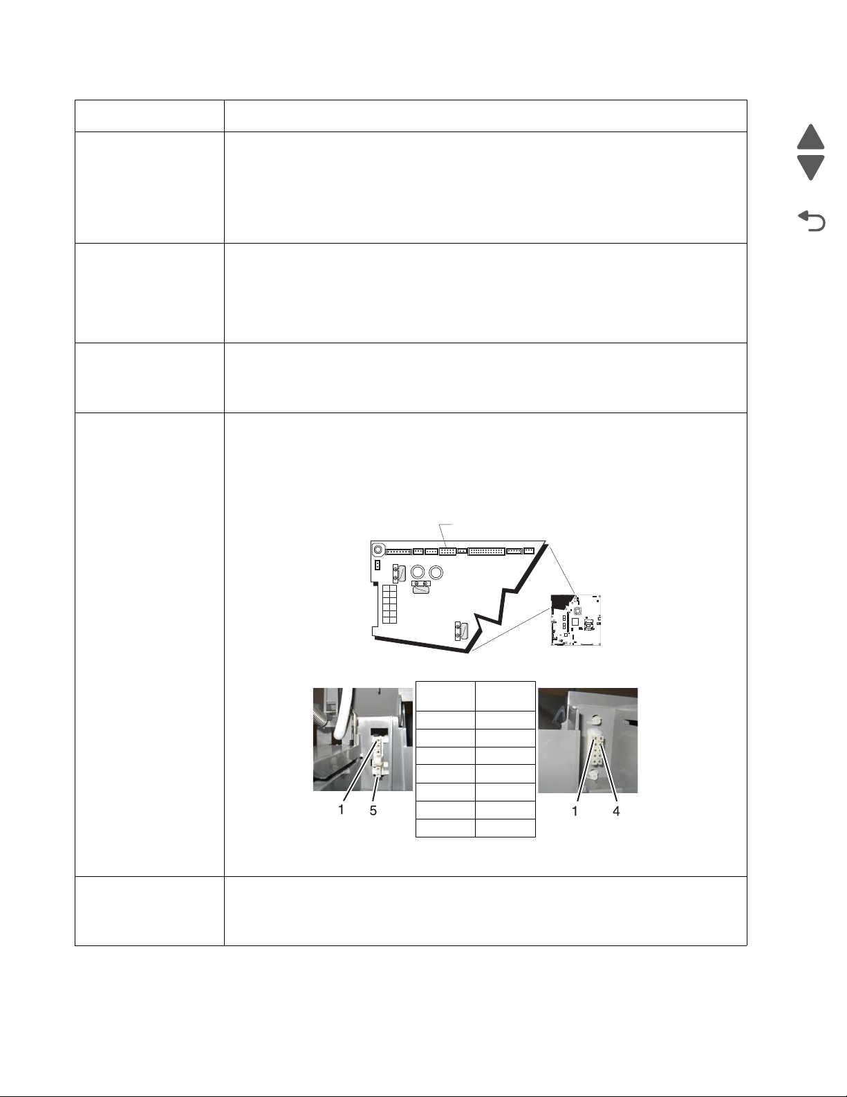
5026
Go Back
Previous
Next
1
JSB1
JBIN1
JFAN1
JFUSER1JFUSER1
JBOR1
JHVPS1JHVPS1
JMIRR1
JBLW1
JCVR1
JLVPS2
JCARTP1
JCARTS1
JCARTS2
JCARTP2
JDVR1
JTPS1
JOPT1
JFDS1
JINT1
JFDPCK1JTRAY1JSEC1
JDX1
JT12JT12
J5
JDIMM1
JOPP1
JT1
JUSB1JUSB1
JBOOT1
JFMUSB1JFMUSB1
J49
JTWF1
JTDBUG1
1
1
1
1
1
1
1
1
1
1
1
1
1
1
1
1
1
1
1
1
1
1
1
1
1
JTLBT1
JPH1
F5
F6
F7
F9
F10
F12
F13
F14F14
1
1
J10
1
1
A
AC autoconnect
DC autoconnect
Pin 1 Pin 3
Pin 5 Pin 4
Pin 6
Pin 7
Pin 8
Pin 9
Pin 10
Error code Action
80 Fuser Life Warning • Select Continue to clear the message and continue printing.
• Show Me, View Supplies, and Tell Me More displays additional information.
• Order a replacement fuser. When print quality is reduced, install the new fuser using the
instruction sheet that comes with the replacement fuser.
Note: Be sure to reset the fuser count. See “Reset Fuser Cnt” on page 3-25.
• If this does not fix the problem, replace the system board. See “System board removal ”
on page 4-153.
80 Replace Fuser • Show Me, View Supplies, and Tell Me More displays additional information.
• Replace the fuser. See “Fuser removal” on page 4-104.
Note: Be sure to reset the fuser count. See “Reset Fuser Cnt” on page 3-25.
•
• If this does not fix the problem, replace the system board. See “System board removal ”
on page 4-153.
80 Fuser Missing • Reinstall the fuser. See “Fuser removal” on page 4-104.
• Reseat connectors behind fuser. They may get dislodged and not make good contact
when the fuser is installed.
• Check the cable connectors for damage at the system board and at the LVPS.
80.41 Fuser missing • Install the fuser. Replace the fuser if the problem persists.
• If the problem continues, turn the printer off and remove the rear frame cover. See “Rear
frame cover removal ” on page 4-33. Check the cable in connector JFUSER1 (A) for
proper connection to the system board, the cable for pinch points, and the cable or the
connector for any other damage. If the connector is damaged on system board, replace
the system board. See “System board removal” on page 4-153. If the fuser cable is
damaged, replace the cable.
82 Waste Toner
Nearly Full
2-12 Service Manual
• Check for the following continuity between the DC autoconnect and FUSER1.
• If continuity is not present, replace the fuser cable. If the problem persists after replacing
cable, replace the system board. See “System board removal” on page 4-153.
• Select Continue to clear the message and continue printing.
• If printing continues, order a replacement waste toner box immediately.
• If the problem persists, open the front access door and check the aligner shaft for binding.
Clear the binding if possible. If not possible, contact your next level of service.
Page 49

5026
Go Back
Previous
Next
Error code Action
82 Replace Waste
Toner
• Replace the waste toner box using the instruction sheet that comes with the replacement
waste toner box.
• Ensure that there is no interference between the waste toner box and the printer.
• If the problem persists, open the front access door and check the aligner shaft for binding.
Clear the binding if possible.
• If the problem persists, replace the system board. See “System board removal” on
page 4-153.
• If the problem persists, contact your next level of service.
82 Waste Toner Missing • Insert the waste toner box.
• Inspect the top cover camshaft assembly for proper operation. When the top access
cover is closed, the printer should mechanically interlock.
• Check the cable in connector JBUMP1on the system board for defects and proper
connection. If the cable wiring or the cable connection is defective, replace the bump
multipurpose feeder/duplex motor assembly. See “Multipurpose feeder (MPF)/duplex
motor assembly removal” on page 4-118. If the cable in JBUMP1 connector is
damaged on the system board, replace the system board. See “System boar d re moval”
on page 4-153.
• Check the aligner shaft and the mechanical system for binds.
• Replace the bump multipurpose feeder/duplex motor assembly. See “Multipurpose
feeder (MPF)/duplex motor assembly removal” on page 4-118.
• If the problem persists, replace the system board. See “System board removal” on
page 4-153.
82.41 If you continuously get this error, then the problem is the aligner motor error. Go to “147.xx,
920.01—POST (power-on self test) aligner error service check” on page 2-50.
83.xx Transfer Module
Life Warning
• Select Continue to clear the message and continue printing.
• Order a replacement transfer module. When print quality is reduced, install the new
transfer module using the instruction sheet that comes with the replacement transfer
module.
• If the problem persists, replace the system board. See “System board removal” on
page 4-153.
83.xx Replace Transfer
Module
83.41 Transfer Module
Missing
84.11 <color> PC Unit
Life Warning
84 Replace <color> PC
Unit
• Replace the transfer module using the instruction sheet that comes with the replacement
transfer module. See “Transfer module removal ” on page4-168.
• If the problem persists, replace the system board. See “System board removal” on
page 4-153.
If the you continuously get this error, go to “920.03, 920.25—Transfer Module Missing
error service check” on page 2-94.
• Select Ignore to clear the message and continue printing.
• Order the specified photoconductor unit. When print quality is reduced, install the new
specified photoconductor unit using the instruction sheet that comes with the replacement
specified photoconductor unit.
• If the problem persists, replace the system board. See “System board removal” on
page 4-153.
• Replace the specified photoconductor unit using the instruction sheet that comes with the
replacement specified photoconductor unit.
• If the problem persists, replace the system board. See “System board removal” on
page 4-153.
Diagnostic information 2-13
Page 50

5026
Go Back
Previous
Next
AB
High voltage
contact path
High voltage
power supply
Finger
Error code Action
84 <color> PC Unit
Missing
• Scroll down the operator panel to see if the printer is showing that all four of the PC units
are missing. If so, check the HVPS cable between the system board and the HVPS.
Ensure that the cable is not plugged in backwards on the HVPS. Disconnect and
reconnect the cable to make sure there is good contact.
• Insert or reinstall the specified photoconductor unit and see if problem clears. See
“Photoconductor unit removal” on page 4-132.
• Remove the top access cover assembly (see “Top acce ss cover assembly removal”
on page 4-40), and confirm that the camshaft follower (A) on the left side is not out of the
groove (B). If the camshaft follower is out of the groove, raise the arm, use a screwdriver
to ease the camshaft follower back into the groove. You need to press down to snap it
into position.
• Check the high voltage contacts path, especially the “finger” on the specified
photoconductor unit (printer is shown with components removed for clarity).
84 <color> PC Unit Near
Life Warning
2-14 Service Manual
• If the contacts are good, replace the HVPS. See “High-voltage power suppl y (HVPS)
removal” on page 4-108.
• If the problem persists, replace the system board. See “System board removal” on
page 4-153.
• Select Ignore to clear the message and continue printing.
• Order the specified photoconductor unit. When print quality is reduced, install the new
specified photoconductor unit using the instruction sheet that comes with the replacement
specified photoconductor unit.
• If the problem persists, replace the system board. See “System board removal” on
page 4-153.
Page 51

5026
Go Back
Previous
Next
Error code Action
88.xx <color> Cartridge
Low
88.xx <color> Cartridge
Nearly Low
88.xx Replace <color>
Cartridge
• Show Me, View Supplies, and Tell Me More displays additional information.
• Replace the specified toner cartridge.
• Select Continue to clear the message and continue printing.
• If the problem persists, replace the system board. See “System board removal” on
page 4-153.
• Show Me, View Supplies, and Tell Me More displays additional information.
• Replace the specified toner cartridge.
• Select Continue to clear the message and continue printing.
• If the problem persists, replace the system board. See “System board removal” on
page 4-153.
• Show Me, View Supplies, and Tell Me More displays additional information.
• Replace the specified toner cartridge.
• Select Continue to clear the message and continue printing.
• If the problem persists, replace the system board. See “System board removal” on
page 4-153.
Diagnostic information 2-15
Page 52

5026
Go Back
Previous
Next
Error codes and messages
Error code Description Action
1xx service error codes
110.01–110.07Mirror
Motor Error
111.01–111.02
Printhead Error
112.01–112.02
Printhead Error
113.01–113.02
Printhead Error
114.01–114.02
Printhead Error
120.00–120.21
Fuser Error
140.01–140.10
Autocomp Motor Error
A mirror motor error has occurred. • POR the printer.
• If the error message persists, go to “110.xx—
Mirror motor service check” on page 2-37.
An error has occurred in the cyan
channel of the printhead.
An error has occurred in the magenta
channel of the printhead.
An error has occurred in the yellow
channel of the printhead.
An error has occurred in the black
channel of the printhead.
An error has occurred in the fuser. • Remove and reseat the fuser. See “Fuser
Tray 1 motor has failed. • POR the printer.
• POR the printer.
• If the error message persists, go to “111.xx,
112.xx, 113.xx, and 114.xx—Printhead error
service check” on page 2-38.
• POR the printer.
• If the error message persists, go to “111.xx,
112.xx, 113.xx, and 114.xx—Printhead error
service check” on page 2-38.
• POR the printer.
• If the error message persists, go to “111.xx,
112.xx, 113.xx, and 114.xx—Printhead error
service check” on page 2-38.
• POR the printer.
• If the error message persists, go to “111.xx,
112.xx, 113.xx, and 114.xx—Printhead error
service check” on page 2-38.
removal” on page 4-104.
• POR the printer.
• If the error message persists, go to “120.xx—
Fuser error service check” on page 2-39.
• If the error message persists, go to “140.xx,
920.02—Autocomp (tray 1) motor error
service check” on page 2-42.
142.09—142.27
Motor Error
143.09–143.27
Motor Error
144.09–144.27
Motor Error
145.09–145.27
Motor Error
2-16 Service Manual
Fuser motor has failed. • POR the printer.
• If the error message persists, go to “142.xx,
906.01–906.04— M otor (fuser) error service
check” on page 2-43.
EP Drive assembly cartridge 1 (top)
motor has failed.
EP Drive assembly cartridge 2
(middle) motor has failed.
EP drive assembly cartridge 3
(bottom) motor has failed.
• POR the printer.
• If the error message persists, go to “143.xx—
Motor (EP drive assembly top cartridge 1
motor) error service check” on page 2-44.
• POR the printer.
• If the error message persists, go to “144.xx—
Motor (EP drive assemb ly middl e cartridge)
error service check” on page 2-46.
• POR the printer.
• If the error message persists, go to “145.xx—
Motor (EP drive assemb ly bottom cartridge)
error service check” on page 2-47.
Page 53

5026
Go Back
Previous
Next
Error code Description Action
146.01–146.08
Motor Error
147.09–147.25
Motor Error
148.01–148.08
Motor Error
155.01, 155.03
Motor Error
156.01, 156.03
Motor Error
160.01–160.06
Motor Error
161.01–161.06
Motor Error
Duplex motor has failed. • POR the printer.
• If the error message persists, go to “146.xx,
148.xx—Motor (MPF/duplex) error service
check” on page 2-48.
Aligner motor has failed. • POR the printer.
• If the error message persists, go to “147.xx,
920.01—POST (power-on self test) aligner
error service check” on page 2-50.
The multipurpose feeder motor has
failed.
• POR the printer.
• If the error message persists, go to “146.xx,
148.xx—Motor (MPF/duplex) error service
check” on page 2-48.
Cam motor failed. • POR the printer.
• If the error message persists, go to “155.xx—
Cam motor error service check” on
page 2-51.
COD (Color On Demand) motor failed. • POR the printer.
• If the error message persists, go to “156.xx—
COD (Color On Demand) motor service
check” on page 2-53.
Tray 2 pick motor failed. • POR the printer.
• If the error message persists, go to “160.xx,
161.xx—Motor Error (option tray 2) ser vice
check” on page 2-54.
Tray 2 feed motor failed. • POR the printer.
• If the error message persists, go to “160.xx,
161.xx—Motor Error (option tray 2) ser vice
check” on page 2-54.
162.01–162.06
Motor Error
163.01–163.06
Motor Error
164.01–164.06
Motor Error
165.01–165.06
Motor Error
166.01–166.06
Motor Error
167.01–167.06
Motor Error
Tray 3 pick motor failed. • POR the printer.
• If the error message persists, go to “162.xx,
163.xx—Motor Error (option tray 3) ser vice
check” on page 2-55.
Tray 3 feed motor failed. • POR the printer.
• If the error message persists, go to “162.xx,
163.xx—Motor Error (option tray 3) ser vice
check” on page 2-55.
Tray 4 pick motor failed. • POR the printer.
• If the error message persists, go to “164.xx,
165.xx—Motor Error (option tray 4) ser vice
check” on page 2-56.
Tray 4 feed motor failed. • POR the printer.
• If the error message persists, go to “164.xx,
165.xx—Motor Error (option tray 4) ser vice
check” on page 2-56.
Tray 5 pick motor failed. • POR the printer.
• If the error message persists, go to “166.xx,
167.xx—Motor Error (option tray 5) ser vice
check” on page 2-57.
Tray 5 feed motor failed. • POR the printer.
• If the error message persists, go to “166.xx,
167.xx—Motor Error (option tray 5) ser vice
check” on page 2-57
Diagnostic information 2-17
Page 54

5026
Go Back
Previous
Next
Error code Description Action
168.xx
HCIT elevator motor error. • POR the printer.
Motor Error
199.xx
Unrecoverable RIP software error. • POR the printer.
Software Error
2xx paper jam messages
200.02 Input sensor is made when printer
tries to print from an idle state.
Possible causes:
• Paper jam leaving page over
sensor
• Defective input sensor
• Faulty system board
200.11 Input sensor does not break.
Possible causes:
• Incorrect media setting
• Incorrect paper loading
• Incorrect media restraint setting
• Transport belt module failure
• Lower guide failure
• Paper pick mechanism failure
• Input sensor failure
• If the error message persists, go to “168.xx—
Motor (HCIT elevator ) error service check ”
on page 2-58.
• If the error message persists, download the RIP
code again.
• Clear away anything in the paper path that might
cause the paper to jam.
• If clearing a paper jam does not fix the problem,
go to “Input sensor service check” on
page 2-128.
1. Clear away anything in the paper path that might
cause the paper to jam.
2. Ensure proper media is set for the type of paper
used.
3. Fan media, and stack flat in the tray.
4. Properly set media restraints in the paper tray.
5. Check the pick arm rolls (tires) and replace if
worn.
If the problem persists, go to “200.11, 250.03—
Paper Jam error service check” on page 2-59.
200.17 Input sensor is made when printer
powers up or covers are closed.
Possible causes:
• Paper jam leaving page over
sensor
• Defective input sensor
• Faulty system board
200.21 Multipurpose feeder/duplex motor
assembly stalled.
Possible causes:
• Waste toner not seated.
• Faulty cable/connector
• 24 V interlock switch not working
correctly
• Faulty align motor
• Faulty system board
200.22 Pick (tray 1) motor stalled.
Possible causes:
• Faulty cable/connector
• Faulty pick motor
• Faulty system board
• Clear away anything in the paper path that might
cause the paper to jam.
• If clearing a paper jam does not fix the problem,
go to “Input sensor service check” on
page 2-128.
• Check that the waste toner is latched correctly in
the printer.
• Check for anything in the paper path that might
cause the paper to jam.
• If clearing a paper jam does not fix the problem,
go to “147.xx, 920.01—POST (power-on self
test) aligner error service check” on
page 2-50.
• Check for anything in the paper path that might
cause the paper to jam.
• If clearing a paper jam does not fix the problem,
go to “140.xx, 920.02—Autocomp (tray 1)
motor error ser vice check” on page 2-42.
2-18 Service Manual
Page 55

5026
Go Back
Previous
Next
Error code Description Action
200.25 Input sensor is made when tray 1 is
installed.
Possible causes:
• Improper placement of paper in
tray 1
• Damaged input sensor flag or
input sensor
• Faulty system board
200.30 Paper hit input sensor too soon.
Possible causes:
• Incorrect paper loading.
• Damaged input sensor flag or
input sensor.
• Faulty system board.
201.02 Bubble sensor active when printing
started.
Possible causes:
• Paper jam leaving page over
sensor.
• Damaged bubble sensor.
• Damaged fuser autoconnect.
• Faulty fuser DC cable connection.
• Faulty fuser.
• Faulty system board.
• Fan media, and stack flat in the tray or
multipurpose feeder.
• Properly set media restraints in the paper tray.
• If clearing a paper jam does not fix the problem,
go to “Input sensor service check” on
page 2-128.
• Fan the media, and then stack flat in the tray.
• Check for anything in the paper path that might
cause the paper to jam.
• The input sensor may not be functioning
properly. Go to “Input sensor service check”
on page 2-128.
1. Clear away anything in the paper path that might
cause the paper to jam.
2. Ensure proper media is set for the type of paper
used.
3. Fan media, and stack flat in the tray.
4. Properly set media restraints in the paper tray.
If the problem persists, go to ““Bubble sensor
service check” on page 2-124.
201.06 Paper is jammed between the input
sensor and the exit sensor.
Possible causes:
• Damaged paper exit sensor or
paper exit sensor flag
• Transport belt module failure
• Aligner failure
• Damaged fuser autoconnect
• Faulty fuser DC cable connection
• Faulty fuser
• Faulty system board
201.07 Exit sensor is made early.
Possible causes:
• Damaged paper exit sensor or
paper exit sensor flag
• Damaged fuser autoconnect
• Faulty fuser DC cable connection
• Faulty fuser
• Faulty system board
• Check for anything in the paper path that might
cause the paper to jam.
•Go to “201.06, 201.31—Paper Jam error
service check” on page 2-60.
• Check for anything in the paper path that might
cause the paper to jam.
• The fuser exit sensor may not be functioning
properly. Go to “Ex it sensor service check”
on page 2-127.
Diagnostic information 2-19
Page 56

5026
Go Back
Previous
Next
Error code Description Action
201.08 Exit sensor is never made.
Possible causes:
• Improper loading
• Paper wrapped in fuser
• Damaged paper exit sensor or
paper exit sensor flag
• Damaged fuser autoconnect
• Faulty fuser DC cable connection
• Faulty fuser
• Faulty system board
201.10 Input sensor flag broke early.
Possible causes:
• Incorrect media set
• Defective input sensor
• Faulty system board
201.17 Power up or cover closed with bubble
sensor active.
Possible causes:
• Paper jam leaving page over
sensor.
• Damaged bubble sensor.
• Damaged fuser autoconnect.
• Faulty fuser DC cable connection.
• Faulty fuser.
• Faulty system board.
• Check for anything in the paper path that might
cause the paper to jam.
• The fuser exit sensor may not be functioning
properly. Go to “Ex it sensor service check”
on page 2-127.
• Check for anything in the paper path that might
cause the paper to jam.
• Ensure the proper media is set for the type of
paper used.
•Go to “Input sensor service check” on
page 2-128.
1. Ensure the proper media is set for the type of
paper used.
2. Fan the media, and stack flat in the tray or
multipurpose feeder.
3. Properly set media restraints in the paper tray.
4. Clear away anything in the paper path that might
cause the paper to jam.
If the problem persists, go to “Bubble sensor
service check” on page 2-124.
201.21 Cartridge motor 1 (top) or cartridge
motor 2 (middle) has stalled.
Possible causes:
• Faulty cable/connector
• Faulty cartridge motor
• Faulty system board
201.24 A 201.08 jam occurred and was not
cleared.
Possible cause—Failure to open and
close the top access door.
201.31 Paper is jammed between the input
sensor and the exit sensor during
warm-up.
Possible causes:
• Damaged paper exit sensor or
paper exit sensor flag.
• Transport belt module failure.
• Lower guide failure
• Damaged fuser autoconnect.
• Faulty fuser DC cable connection.
• Faulty fuser.
• Faulty system board.
• Check for anything in the paper path that might
cause the paper to jam.
• If clearing a paper jam does not fix the problem,
go to “143.xx—Mo tor (EP drive assembly top
cartridge 1 mot or) error service check” on
page 2-44, and then go to “144.xx—Motor (EP
drive assembly middle cartridge) error
service check” on page 2-46, if necessary.
This error is generated as a protection for possible
paper wrap in the fuser.
• Open the top access door, and check for a
paper jam. Close the top access door.
•Go to “Exit sensor service check” on
page 2-127.
• Check for anything in the paper path that might
cause the paper to jam.
•Go to “201.06, 201.31—Paper Jam error
service check” on page 2-60.
2-20 Service Manual
Page 57

5026
Go Back
Previous
Next
Error code Description Action
202.02 Exit sensor is made when printer tries
to print from an idle state.
Possible causes:
• Damaged paper exit sensor or
paper exit sensor flag
• Damaged fuser autoconnect
• Faulty fuser DC cable connection
• Faulty fuser
• Faulty system board
202.12 Exit sensor broke early.
Possible causes:
• Damaged paper exit sensor or
paper exit sensor flag
• Faulty fuser
• Faulty system board
202.13 Exit sensor never broke.
Possible causes:
• Damaged paper exit sensor or
paper exit sensor flag
• Faulty fuser
• Faulty system board
• Faulty output bin flag
202.17 Exit sensor is made when the printer
powers up or covers are closed.
Possible causes:
• Damaged paper exit sensor or
paper exit sensor flag
• Damaged fuser autoconnect
• Faulty fuser DC cable connection
• Faulty fuser
• Faulty system board
• Check for anything in the paper path that might
cause the paper to jam.
• The fuser exit sensor may not be functioning
properly. Go to “Ex it sensor service check”
on page 2-127.
The fuser exit sensor may not be functioning
properly. Go to “Ex it sensor service check” on
page 2-127.
• Check exit sensor flag on fuser for proper
operation. Ensure that paper is not hanging on
the flag.
• The fuser exit sensor may not be functioning
properly. Go to “Ex it sensor service check”
on page 2-127.
• Check for anything in the paper path that might
cause the paper to jam.
• The fuser exit sensor may not be functioning
properly. Go to “Ex it sensor service check”
on page 2-127.
202.21 Fuser motor stalled.
Possible causes:
• Faulty cable/connector
• Faulty fuser motor
• Faulty system board
202.31 Paper jam at exit sensor during warmup.
Possible causes:
• Damaged paper exit sensor or
paper exit sensor flag.
• Damaged fuser autoconnect.
• Faulty fuser DC cable connection.
• Faulty fuser.
• Faulty system board.
• Check for anything in the paper path that might
cause the paper to jam.
• If clearing a paper jam does not fix the problem,
go to “142.xx, 906.01–906.04—Motor (fuser)
error service check” on page 2-43.
• Check for anything in the paper path that might
cause the paper to jam.
• The fuser exit sensor may not be functioning
properly. Go to “Ex it sensor service check”
on page 2-127.
Diagnostic information 2-21
Page 58

5026
Go Back
Previous
Next
Error code Description Action
203.09 During duplex printing retract, the exit
sensor is never made.
Possible causes:
• Damaged paper exit sensor or
paper exit sensor flag
• Transport belt module failure
• Damaged fuser autoconnect
• Faulty fuser DC cable connection
• Faulty fuser
• Faulty system board
203.14 During duplex printing retract, the exit
sensor broke early.
Possible causes:
• Incorrect paper settings
• Damaged paper exit sensor or
paper exit sensor flag
• Faulty fuser
• Faulty system board
203.15 During duplex printing, the exit sensor
never broke.
Possible causes:
• Damaged paper exit sensor or
paper exit sensor flag
• Obstructed duplex
• Faulty fuser
• Faulty system board
• Duplex motor failure
• Check for anything in the paper path that might
cause the paper to jam.
• The fuser exit sensor may not be functioning
properly. Go to “2 03.09—Paper Jam error
service check” on page 2-63.
• Ensure proper media is set for the type of paper
used.
• The fuser exit sensor may not be functioning
properly. Go to “Ex it sensor service check”
on page 2-127.
• Check the duplex paper path for damage that
would obstruct the print. If damage is found,
replace the front door assembly. See “Front
door assembly removal ” on page4-93.
• The fuser exit sensor may not be functioning
properly. Go to “Ex it sensor service check”
on page 2-127.
• The duplex motor may not be functioning
properly. Go to “1 46.xx, 148.xx—Motor (MPF/
duplex) error service check” on page 2-48.
203.20 During duplex, the page made the
input sensor before the previous page
cleared the bubble sensor.
Possible causes:
• Defective input sensor.
• Faulty system board.
230.03 During duplex printing, the input
sensor is never broke.
Possible causes:
• Obstructed duplex path
• Duplex drive failure
• Defective input sensor
• Faulty system board
230.05 During duplex printing, the input
sensor is not made.
Possible causes:
• Obstructed duplex path
• Defective input sensor
• Faulty system board
• Faulty duplex drive
• Check for anything in the duplex paper path that
might cause the paper to jam. This includes the
paper guides in tray 1.
• If clearing the paper jam does not fix the
problem and the paper is fan-folded, replace the
front access assembly. See “Front door
assembly removal” on page 4-93.
• If clearing a paper jam does not fix the problem,
go to “Input sensor service check” on
page 2-128.
• Check for anything in the duplex paper path that
might cause the paper to jam. This includes the
paper guides in tray 1.
•Go to “230.03, 230.05—Paper Jam error
service check” on page 2-66.
• Check for anything in the duplex paper path that
might cause the paper to jam. This includes the
paper guides in tray 1.
•Go to “230.03, 230.05—Paper Jam error
service check” on page 2-66.
2-22 Service Manual
Page 59

5026
Go Back
Previous
Next
Error code Description Action
230.21 Duplex motor stalled.
Possible causes:
• Obstructed duplex path
• Defective duplex motor
• Faulty system board
241.03 While feeding from tray 1, the input
sensor does not break.
Possible causes:
• Incorrect media setting
• Incorrect paper loading
• Incorrect media restraint setting
• Paper pick mechanism failure
• Transport belt motor failure
241.05 While feeding from tray 1, the input
sensor is never made.
Possible causes:
• Incorrect paper loading
• Incorrect media restraint setting
• Pick art rolls (tires) failure
• Paper pick mechanism failure
• System board failure
241.21 Tray 1 motor stalled.
Possible causes:
• Incorrect paper loading
• Paper pick mechanism failure
• System board failure
• Check for anything in the duplex paper path that
might cause the paper to jam. This includes the
paper guides in tray 1.
• If clearing a paper jam does not fix the problem,
go to “146.xx, 148.xx—Motor (MPF/duplex)
error service check” on page 2-48.
1. Clear away anything in the paper path that might
cause the paper to jam.
2. Ensure proper media is set for the type of paper
used.
3. Fan media, and stack it flat in the tray or
multipurpose feeder.
4. Properly set media restraints in paper tray.
5. Check the pick arm rolls (tires) and replace if
worn.
If the problem persists, go to “200.11, 250.03—
Paper Jam error service check” on page 2-59.
1. Remove all media present in the paper path.
2. Fan media, and stack it flat in the tray or
multipurpose feeder.
3. Properly set media restraints in paper tray.
4. Check the pick arm rolls (tires) and replace if
worn.
If the problem persists, go to “140.xx, 920.02—
Autocomp (tray 1) motor error service check”
on page 2-42.
1. Remove all media present in the paper path.
2. Ensure proper media is set for the type of paper
used.
3. Fan media, and stack it flat in the tray or
multipurpose feeder.
If the previous actions do not fix the problem, go to
“140.xx, 920.02—Autocomp (tray 1) moto r error
service check” on page 2-42.
242.02 Tray 2 pass thru sensor made at
POR.
Possible causes:
• Paper jam leaving paper over
sensor
• Defective pass thru sensor
242.03 Pick timeout from tray 2 exceeded
without a tray 2 sensor break.
Possible causes:
• Incorrect media setting
• Incorrect paper loading
• Incorrect media restraint setting
• Tray 2 assembly failure
• Aligner failure
• Transport belt module failure
• Check for anything in the paper path that might
cause the paper to jam.
• If the error persists, go to “242.02—Paper Jam
service check” on page 2-68.
1. Remove all media present in the paper path.
2. Ensure proper media is set for the type of paper
used in tray 2.
3. Fan media, and stack flat in tray 2.
4. Properly set media restraints in tray 2.
If the paper jam message persists, go to “242.03,
242.11—Paper Jam service check” on
page 2-69.
Diagnostic information 2-23
Page 60

5026
Go Back
Previous
Next
Error code Description Action
242.05 Tray 2 picked, but page failed to reach
the option sensor in time.
Possible causes:
• Incorrect media setting
• Incorrect paper loading
• Incorrect media restraint setting
• Loading card stock from the
special media tray above the fill
line.
242.10 Tray 2 page exits pass thru made
early.
Possible causes:
• Defective pass thru sensor
• Faulty cable in the connector
JOPT1 on system board.
242.11 Tray 2 sensor never broke.
Possible causes:
• Incorrect tray 2 media setting
• Incorrect Tray 2 paper loading
• Incorrect media restraint setting
• Paper tray 2 failure
• Aligner failure
• Transport belt module failure
• Loading card stock from the
special media tray above the fill
line.
• High humidity (replace paper)
1. Ensure proper media is set for the type of paper
used in tray 2.
2. Fan media, and stack flat in tray 2.
3. Properly set the media restraints in tray 2.
4. Check the pick arm rolls (tires) in tray 2 and
replace if worn.
If the previous actions do not fix the problem, go to
“242.05—Paper Jam service check” on
page 2-70.
• Ensure the proper media is set for the type of
paper used in tray 2.
• Check for anything in the paper path that might
cause the paper to jam.
• The exits pass thru sensor may not be
functioning properly. Go to “242.10—Paper
Jam service check” on page 2-71.
1. Ensure the proper media is set for the type of
paper used in tray 2.
2. Fan media, and then stack flat in tray 2.
3. Properly set the media restraints in tray 2.
Go to “242.03, 242.11—Paper Jam service
check” on page 2-69.
242.17 Tray 2 detected a jam from idle.
Possible causes:
• Paper jam leaving page over
sensor
• Defective input sensor
• Faulty system board
242.26 While feeding from tray 2, the pass
thru sensor is not made.
Possible causes:
• Incorrect paper loading for lower
tray
• Incorrect media restraint setting
for lower tray
• Paper tray 2 assembly failure
• Lower tray 3 assembly failure
242.27 While feeding from a lower tray, pass
thru sensor did not break.
Possible causes:
• Paper tray 2 assembly failure
(feed through roller)
• Aligner failure
• Transport belt motor failure
• Clear away anything in the paper path that might
cause the paper to jam.
• If clearing a paper jam does not fix the problem,
“242.17—Paper Jam service check” on
page 2-72.
1. Clear away anything in the paper path that might
cause the paper to jam.
2. Ensure the proper media is set for the type of
paper used in the lower tray.
3. Fan the media, and then stack flat in the lower
tray.
4. Properly set the media restraints in the lower
tray.
5. Check the pick arm rolls (tires) in the lower tray,
and then replace if worn.
If the problem persists, go to “242.26—Paper Jam
service check” on page 2-73.
• Clear away anything in the paper path that might
cause the paper to jam.
• Reseat option tray 2.
•Go to “242.27—Paper Jam service check” on
page 2-73.
2-24 Service Manual
Page 61

5026
Go Back
Previous
Next
Error code Description Action
242.29 Tray 2 is not ready or missing while
printing.
Possible cause is paper tray 2
assembly failure
243.02 Tray 3 pass thru sensor made at
POR.
Possible causes:
• Paper jam leaving page over the
sensor
• Defective pass thru sensor
243.03 Pick timeout from tray 3 exceeded
without a tray 3 sensor break.
Possible causes:
• Tray 3 incorrect media setting
• Tray 3 incorrect paper loading
• Tray 3 incorrect media restraint
setting
• Tray 3 assembly failure
243.05 Tray 3 picked, but page failed to reach
the option sensor in time,
Possible causes:
• Tray 3 incorrect media setting
• Tray 3 incorrect paper loading
• Tray 3 incorrect media restraint
setting
• Tray 3 paper pick mechanism
failure
• Loading card stock from the
special media tray above the fill
line.
• Make sure that tray 2 is correctly inserted.
•Go to “242.29—Paper Jam service check” on
page 2-74.
• Check for anything in the paper path that might
cause the paper to jam.
• If clearing a paper jam does not fix the problem,
see “243.02—Paper Jam service check” on
page 2-74.
1. Remove all media present in the paper path.
2. Ensure proper media is set for the type of paper
used in tray 3.
3. Fan media, and stack flat in tray 3.
4. Properly set media restraints in tray 3.
If the previous actions do not fix the problem, go to
“243.03, 243.11—Paper Jam service check ” on
page 2-75.
1. Ensure proper media is set for the type of paper
used in tray 3.
2. Fan media, and stack flat in tray 3.
3. Properly set the media restraints in tray 3.
4. Check the pick arm rolls (tires) in tray 3 and
replace if worn.
If the previous actions do not fix the problem, go to
“243.05—Paper Jam service check” on
page 2-76.
243.10 Tray 3 page exit pass thru sensor
broken early.
Possible causes:
• Defective pass thru sensor
• Faulty cable in connector OPT1.
243.11 Tray 3 sensor never broke.
Possible causes:
• Incorrect tray 3 media setting
• Incorrect tray 3 paper loading
• Incorrect media restraint setting
• Paper tray failure
• Aligner failure
• Transport belt module failure
• Loading card stock from the
special media tray above the fill
line.
• High humidity (replace paper)
• Make sure the proper media is set for the type of
paper used in tray 3.
• Check for anything in the paper path that might
cause the paper to jam.
• The exit pass thru sensor may not be
functioning properly. Go to “243.10—Paper
Jam service check” on page 2-77.
1. Ensure the proper media is set for the type of
paper used in tray 3.
2. Fan media, and then stack flat in tray 3.
3. Properly set the media restraints in tray 3.
4. Check the pick arm rolls (tires) in tray 3 and
replace if worn.
If the problem persists, Go to “243.0 3, 243. 11—
Paper Jam service check” on page 2-75.
Diagnostic information 2-25
Page 62

5026
Go Back
Previous
Next
Error code Description Action
243.17 Tray 3 detected a jam from idle.
Possible causes:
• Paper jam leaving page over
sensor
• Defective input sensor
• Faulty system card
243.26 While feeding from a lower tray, tray 3
pass thru sensor is not made.
Possible causes:
• Incorrect paper loading for lower
tray
• Incorrect media restraint setting
for lower tray
• Paper tray 3 assembly failure
• Lower tray 4 assembly failure
243.27 While feeding from a lower tray, tray 3
pass thru sensor did not break.
Possible cause is a paper tray 3
assembly failure
243.29 Tray 3 is not ready while printing.
Possible cause is paper tray 3
assembly failure.
• Clear away anything in the paper path that might
cause the media to jam.
• If the problem persists, go to “243.17—Paper
Jam service check” on page 2-78.
1. Clear away anything in the paper path that might
cause the media to jam.
2. Make sure proper media is set for the type of
paper used in lower feeding tray.
3. Fan media, and stack flat in the lower feeding
tray.
4. Properly set media restraints in the lower
feeding tray.
5. Check the pick arm rolls in lower tray and
replace if worn.
If the problem persists, go to “243.26—Paper Jam
service check” on page 2-79.
• Clear away anything in the paper path that might
cause the paper to jam.
• Reseat option tray 3
• If the problem persists, go to “243.27—Paper
Jam service check” on page 2-79.
• Make sure that tray 3 is correctly inserted.
• If the problem persists, go to “243.29—Paper
Jam service check” on page 2-79.
244.02 Tray 4 pass thru sensor made at
POR.
Possible causes:
• Paper jam leaving page over the
sensor
• defective pass thru sensor
244.03 Pick timeout from tray 4 was
exceeded without a tray 4 sensor
break.
Possible causes:
• Tray 4 incorrect media setting
• Tray 4 incorrect paper loading
• Tray 4 incorrect media restraint
setting
• Tray 4 assembly failure
• Aligner failure
• Transport belt module failure
• Check for anything in the paper path that might
cause the paper to jam.
• If the problem persists, go to “244.02—Paper
Jam service check” on page 2-80.
1. Remove all media present in the paper path.
2. Maker sure proper media is set for the type of
paper used in tray 4.
3. Fan the media, and stack flat in tray 4.
4. Properly set media restraints in tray 4.
If the problem persists, go to “244.03, 244.11—
Paper Jam service check” on page 2-81.
2-26 Service Manual
Page 63

5026
Go Back
Previous
Next
Error code Description Action
244.05 Tray 4 picked, but page failed to reach
the option sensor in time.
Possible causes:
• Tray 4 incorrect media setting
• Tray 4 incorrect paper loading
• Tray 4 incorrect media restraint
setting
• Tray 4 paper pick mechanism
assembly failure
• Loading card stock from the
special media tray above the fill
line.
244.10 Tray 4 page exit pass thru made early.
Possible causes:
• Defective pass thru sensor
• Faulty cable in connector OPT1
244.11 Tray 4 sensor never broke.
Possible causes:
• Incorrect tray 4 media setting
• Incorrect tray 4 paper loading
• Incorrect media restraint setting
• Paper tray failure
• Aligner failure
• Transport belt module failure
• Loading card stock from the
special media tray above the fill
line.
• High humidity (replace paper)
1. Ensure proper media is set for the type of paper
used in tray 4.
2. Fan media, and stack flat in tray 4.
3. Properly set the media restraints in tray 4.
4. Check the pick arm rolls (tires) in tray 4 and
replace if worn.
If the problem persists, go to “244.05—Paper Jam
service check” on page 2-81.
• Make sure proper media is set for the type of
paper used in tray 4.
• Check for anything in the paper path that might
cause the paper to jam.
• The exit pass thru sensor may not be
functioning properly. Go to “244.10—Paper
Jam service check” on page 2-83.
1. Ensure the proper media is set for the type of
paper used in tray 4.
• Fan media, and then stack flat in tray 4.
• Properly set the media restraints in tray 4.
If the problem persists, go to “244.03, 244.11—
Paper Jam service check” on page 2-81.
244.17 Tray 4 detected a jam from idle.
Possible causes:
• Paper jam leaving page over the
sensor
• defective input sensor
• Faulty system board
244.26 While feeding from a lower tray, tray 4
pass thru sensor is not made.
Possible causes:
• Incorrect paper loading for the
lower tray
• Incorrect media restraint setting
for the lower tray
• Paper tray 4 assembly failure
• Paper tray 5 assembly failure
244.27 While feeding from a lower tray, tray 4
pass thru sensor did not break.
Possible cause is paper tray 4
assembly failure.
• Clear away anything in the paper path that might
cause the paper to jam.
• If clearing a paper jam does not fix the problem,
go to “243.17—Paper Jam service check” on
page 2-78.
1. Clear away anything in the paper path that might
cause the paper to jam.
2. Make sure the proper media is set for the type of
paper used in the lower tray.
3. Fan the media, and stack flat in the lower tray.
4. Properly set the media restraints in the lower
tray.
5. Check the pick arm rolls in the lower feeding tray
and replace if worn.
If the problem persists, go to “244.26—Paper Jam
service check” on page 2-84.
• Clear away anything in the paper path that might
cause the paper to jam.
• Reseat option tray 4.
• If the problem persists, go to “244.27—Paper
Jam service check” on page 2-84.
Diagnostic information 2-27
Page 64

5026
Go Back
Previous
Next
Error code Description Action
244.29 Tray 4 is not ready, or missing while
printing.
Possible cause is paper tray 4
assembly failure.
245.02 Tray 5 pass thru sensor made at
POR.
Possible causes:
• Paper jam leaving a page over the
sensor
• Defective pass thru sensor
245.03 Pick timeout from tray 5 exceeded
without a tray sensor break.
Possible causes:
• Tray 5 incorrect media setting
• Tray 5 incorrect paper loaded
• Tray 5 incorrect media restraint
setting
• Tray 5 assembly failure
• Aligner failure
• Transport module failure
245.05 Possible causes:
• Incorrect media setting
• Incorrect paper loading
• Incorrect media restraint setting
• Tray 5 paper pick mechanism
• Loading card stock from the
special media tray above the fill
line.
• Make sure that tray 4 is correctly inserted.
• If the problem persists, go to “244.29—Paper
Jam service check” on page 2-85.
• Check for anything in the paper path that might
cause the media to jam.
• If the problem persists, go to “245.17—Paper
Jam service check” on page 2-89.
1. Remove all media present in the paper path.
2. Make sure proper media is set for the type of
paper used in tray 5.
3. Fan the media, and stack flat in tray 5.
4. Properly set the media restraints in tray 5.
If the problem persists, go to “245.03, 245.11—
Paper Jam service check” on page 2-86.
1. Ensure proper media is set for the type of paper
used in tray 5.
2. Fan media, and stack flat in tray 5.
3. Properly set the media restraints in tray 5.
4. Check the pick arm rolls (tires) in tray 5 and
replace if worn.
If the problem persists, go to “245.05—Paper Jam
service check” on page 2-87.
245.10 Tray 5 page exits pass thru sensor
broken early.
Possible causes:
• Defective pass thru sensor
• Faulty cable in connector JOPT1
on the system board
245.11 Tray 5 sensor never broke.
Possible causes:
• Incorrect tray 5 media setting
• Incorrect tray 5 paper loading
• Incorrect media restraint setting
• Paper tray failure
• Aligner failure
• Transport belt module failure
• Loading card stock from the
special media tray above the fill
line.
• High humidity (replace paper)
• Make sure the proper media is set for the type of
paper used in tray 5.
• Check for anything in the paper path that might
cause the paper to Jam.
• The exits pass thru sensor may not be
functioning properly. Go to “245.10—Paper
Jam service check.
1. Ensure the proper media is set for the type of
paper used in tray 5.
2. Fan media, and then stack flat in tray 5.
3. Properly set the media restraints in tray 5.
4. Check the pick arm rolls (tires) in tray 5 and
replace if worn.
If the problem persists, go to “245.03, 245.11—
Paper Jam service check” on page 2-86.
2-28 Service Manual
Page 65

5026
Go Back
Previous
Next
Error code Description Action
245.17 Tray 5 detected a jam from idle.
Possible causes:
• Paper jam leaves a page over the
sensor
• Defective input sensor
• Faulty system board
245.29 Tray 5 is not ready or missing while
printing.
Possible cause paper tray 5 assembly
failure.
250.03 While feeding from the multipurpose
feeder, the input sensor did not break.
Possible causes:
• Incorrect media setting
• Incorrect paper loading
• Incorrect media restraint setting
• Transport belt failure
• Paper tray failure
250.05 While feeding from the multipurpose
feeder, the input sensor is not made.
Possible causes:
• Incorrect media setting
• Incorrect paper loading
• Incorrect media restraint setting
• Multipurpose feeder pick
mechanism failure
• System board failure
• Clear away anything in the paper path that might
cause the paper to jam.
• If the problem persists, go to “245.17—Paper
Jam service check.
• Make sure that tray 5 is correctly inserted.
• If the problem persists, go to “245.29—Paper
Jam service check” on page 2-90.
1. Remove all media present in the paper path.
2. Ensure proper media is set for the type of paper
used.
3. Fan media, and stack it flat in the tray or
multipurpose feeder.
4. Properly set media restraints in the paper tray.
5. Replace the paper tray.
If the problem persists, to “200.11, 250.03—Paper
Jam error service check” on page 2-59.
1. Remove all the media present in the paper path.
2. Ensure proper media is set for the type of paper
used.
3. Fan media, and stack it flat in the tray or
multipurpose feeder.
4. Properly set media restraints in the paper tray.
5. Check the MP feeder pick tires and clean if
necessary.
6. Check the multipurpose feeder pick arm rolls
(tires), and then clean if necessary.
7. Replace the paper tray.
250.21 Multipurpose feeder motor stalled.
Possible causes:
• Multipurpose feeder motor failure
• Cabling failure
• Multipurpose feeder gear
assembly failure
• System board failure
• Remove all the media present in the paper path.
• Ensure proper media is set for the type of paper
used.
• Fan media, and stack it flat in the tray or
multipurpose feeder.
If the previous actions do not fix the problem, go to
“146.xx, 148.xx—Motor (MPF/duplex) error
service check” on page 2-48.
Diagnostic information 2-29
Page 66

5026
Go Back
Previous
Next
Error code Description Action
9xx service error messages
900.00–900.99
Software Error
(except 900.05)
900.05
Software Error.
902.01–902.99
Engine Software Error
(except 902.59 and
902.60)
902.59
Error
902.60
Error
903.01–903.15
Engine Software Error
904.01–904.04
Software Error
Unrecoverable RIP software error. Go to “900.00–900.99 (except 900.05)—System
software error service check” on page 2-90.
Transfer module has failed • POR the printer.
• If the error message persists, go to “900.05—
Transfer module erro r service check” on
page 2-93.
Unrecoverable system software
errors.
• POR the printer.
• If the error message persists, replace the
system board. See “System board removal”
on page 4-153.
RIP NVRAM MGR problem. POR the printer.
If the error message persists, go to “902.59—
Engine software error, NVRAM MGR problem
service check” on page 2-94.
Error communicating with cartridge. 1. POR the printer.
2. If the error message persists, check for the
correct cartridges.
3. Replace the cartridges.
Unrecoverable system software
errors.
• POR the printer.
• If the error message persists, replace the
system board. See “System board removal”
on page 4-153.
Unrecoverable system software
errors.
• POR the printer.
• If the error message persists, replace the
system board. See “System board removal”
on page 4-153.
905.00–905.99
Software Error
910.xx
Engine Software Error
920.01
POST Error
920.02
POST Error
920.03
POST Error
920.04
POST Error
2-30 Service Manual
Unrecoverable system software
errors.
• POR the printer.
• If the error message persists, replace the
system board. See “System board removal”
on page 4-153.
RIP software error interface violation • POR the printer.
• If the error persists, replace the system board.
See “System board removal” on page 4-153.
Multipurpose feeder/duplex motor
assembly not connected.
• POR the printer.
• If the error message persists, go to “147.xx,
920.01—POST (power-on self test) aligner
error service check” on page 2-50.
Tray 1 motor not connected. • POR the printer.
• If the error message persists, go to “140.xx,
920.02—Autocomp (tray 1) motor error
service check” on page 2-42.
Transfer module not connected. • POR the printer.
• If the error message persists, go to “920.03,
920.25—Transfer Module Missing error
service check” on page 2-94.
Fuser motor not connected. • POR the printer.
• If the error message persists, go to “920.04—
POST (power-on self test) error service
check” on page 2-96.
Page 67

5026
Go Back
Previous
Next
Error code Description Action
920.05
POST Error
920.06
POST Error
920.07
POST Error
920.08
POST Error
920.09
POST Error
920.10
POST Error
920.11
POST Error
Printhead motor not connected. • POR the printer.
• If the error message persists, go to “920.05—
POST (power-on self test) printhead motor
not connected error service check” on
page 2-98.
Input sensor not connected. • POR the printer.
• If the error message persists, go to “Input
sensor service check” on page 2-128.
Narrow media sensor not connected. • POR the printer.
• If the error message persists, go to “920.07—
POST (power-on self test) error service
check” on page 2-99.
Exit sensor not connected. • POR the printer.
• If the error message persists, go to “Exit
sensor service check” on page 2-127.
Four toner sensors are not connected. • POR the printer.
• If the error message persists, go to “920.09—
POST (power-on self test)—Four toner
sensors not connected error service check”
on page 2-101.
Three toner sensors are not
connected.
• POR the printer.
• If the error message persists, go to “920.10—
POST—Three toner sensors not connected
error service check” on page 2-102.
Two toner sensors are not connected. • POR the printer.
• If the error message persists, go to “920.11—
POST (power-on self test)—Two toner
sensors not connected error service check”
on page 2-102.
920.12
POST Error
920.13
POST Error
920.14
POST Error
920.15
POST Error
920.16
POST Error
One toner sensor is not connected. • POR the printer.
• If the error message persists, go to “920.12—
POST (power-on self test)—One sensor not
connected error service check” on
page 2-104.
Cartridge motor 1 (top) not connected. • POR the printer.
• If the error message persists, go to “920.13—
POST (power-on self test) cartridge motor 1
not connected error service check” on
page 2-105.
Cartridge motor 2 (middle) is not
connected.
• POR the printer.
• If the error message persists, go to “920.14—
POST (power-on self test)—Cartridge motor
2 not connected error service check” on
page 2-106.
Bad transfer module NVRAM data. • POR the printer.
• If the error message persists, go to “920.15,
920.20—POST (power-on self test)—Bad
transfer module NVRAM data error ser vice
check” on page 2-107.
Bad printhead NVRAM data. • POR the printer.
• If the error message persists, go to
POST (power-on self test)—Bad printhead
NVRAM data error service check” on
page 2-108.
“920.16—
Diagnostic information 2-31
Page 68

5026
Go Back
Previous
Next
Error code Description Action
920.17
POST Error
920.18
POST Error
920.19
POST Error
920.20
POST Error
920.21
POST Error
920.22
POST Error
Output bin cable not connected. • POR the printer.
• If the error message persists, go to “920.17—
POST (power-on self test)—Output bin cabl e
not connected error service check” on
page 2-109.
Cartridge motor 3 (bottom) is not
connected.
• POR the printer.
• If the error message persists, go to “920.18—
POST (power-on self test)—Cartridge motor
3 not connected error service check” on
page 2-110.
Stepper motor not connected. • POR the printer.
• If the error message persists, go to “920.19—
POST (power-on self test)—Tr ansfer module
stepper motor not connected error servic e
check” on page 2-111.
Incompatible transfer module. • POR the printer.
• If the error message persists, go to “920.15,
920.20—POST (power-on self test)—Bad
transfer module NVRAM data error ser vice
check” on page 2-107.
+24 V power supply failure. • POR the printer.
• If the error message persists, replace the low-
voltage power supply. See “Low-voltage
power supply (LVPS) removal” on
page 4-112.
Fuser bubble sensor is not connected. If the error message persists, go to “Bubble
sensor service check” on page 2-124.
920.23
POST Error
920.25
POST Error
920.27
POST Error
920.28
POST Error
920.29
POST Error
Duplex motor is not connected. • POR the printer.
• If the error message persists, go to “920.23—
POST (power-on self test)—Duplex motor
not connected error service check” on
page 2-114.
Bad temperature and humidity sensor. • POR the printer.
• If the problem persists, go to “920.03, 920.25—
Transfer Module Missi ng error service
check” on page 2-94.
Option board ID unknown. If the error message persists, go to “920.27,
920.28, 920.29—POST (power on self test)
service check” on page 2-116.
Option type unknown. If the error message persists, go to “920.27,
920.28, 920.29—POST (power on self test)
service check” on page 2-116.
Option product ID unknown. If the error message persists, go to “920.27,
920.28, 920.29—POST (power on self test)
service check” on page 2-116.
2-32 Service Manual
Page 69

5026
Go Back
Previous
Next
Error code Description Action
920.30
POST Error
920.31
POST Error
925.01
Fan Error
925.02
Blower Error
925.03
Fan Error
925.04
Blower Error
Option sensor disconnected. Use the following list to determine which service
check to use:
•Tray 2—Go to “242.02—Paper Jam service
check” on page 2-68.
•Tray 3—Go to “243.02—Paper Jam service
check” on page 2-74.
•Tray 4—Go to “244.02—Paper Jam service
check” on page 2-80.
•Tray 5—Go to “245.02—Paper Jam service
check” on page 2-85.
Option hardware error (generic) Contact your next level of support.
Fan has stalled. • POR the printer.
• If the error message persists, go to “925.01,
925.03, 925.05—Fan error service check” on
page 2-116.
Blower has stalled. • POR the printer.
• If the error message persists, go to “925.02,
925.04, 925.06—Cartridge cooli ng fan error
service check” on page 2-117.
Fan has stalled. • POR the printer.
• If the error message persists, go to “925.01,
925.03, 925.05—Fan error service check” on
page 2-116.
Blower has stalled. • POR the printer.
• If the error message persists, go to “925.02,
925.04, 925.06—Cartridge cooli ng fan error
service check” on page 2-117.
925.05
Fan Error
925.06
Blower Error
945.01
Transfer Roll
945.02
Transfer Roll
945.03
Transfer Roll
945.04
Transfer Roll
Fan has stalled. • POR the printer.
• If the error message persists, go to “925.01,
925.03, 925.05—Fan error service check” on
page 2-116.
Blower has stalled. • POR the printer.
• If the error message persists, go to “925.02,
925.04, 925.06—Cartridge cooli ng fan error
service check” on page 2-117.
Yellow transfer roll has failed. • POR the printer.
• If the error message persists, go to “945.xx,
947.xx—Transf er rol l er ror servi ce check” on
page 2-118.
Cyan transfer roll has failed. • POR the printer.
• If the error message persists, go to “945.xx,
947.xx—Transf er rol l er ror servi ce check” on
page 2-118.
Magenta transfer roll has failed. • POR the printer.
• If the error message persists, go to “945.xx,
947.xx—Transf er rol l er ror servi ce check” on
page 2-118.
Black transfer roll has failed. • POR the printer.
• If the error message persists, go to “945.xx,
947.xx—Transf er rol l er ror servi ce check” on
page 2-118.
Diagnostic information 2-33
Page 70

5026
Go Back
Previous
Next
Error code Description Action
947.01
Transfer Roll
947.02
Transfer Roll
947.03
Transfer Roll
947.04
Transfer Roll
950.00–950.29
NVRAM Failure
951.01–951.99
NVRAM Failure
952.01–952.99
NVRAM Error
Yellow transfer roll has failed. • POR the printer.
• If the error message persists, go to “945.xx,
947.xx—Transf er rol l er ror servi ce check” on
page 2-118.
Cyan transfer roll has failed. • POR the printer.
• If the error message persists, go to “945.xx,
947.xx—Transf er rol l er ror servi ce check” on
page 2-118.
Magenta transfer roll has failed. • POR the printer.
• If the error message persists, go to “945.xx,
947.xx—Transf er rol l er ror servi ce check” on
page 2-118.
Black transfer roll has failed. • POR the printer.
• If the error message persists, go to “945.xx,
947.xx—Transf er rol l er ror servi ce check” on
page 2-118.
A mismatch between the operator
panel assembly and the system
board.
• POR the printer.
• If the error message persists, go to “950.00–
950.29—EPROM mismatch failure” on
page 2-120
System board NVRAM failure. • POR the printer.
• If the error message persists, replace the
system board. See “System board removal”
on page 4-153.
CRC error has occurred. This is
Perform a POR to clear the error.
recoverable.
953.01–953.99
NVRAM Failure
954.01–954.99
NVRAM Failure
955.01–955.99
Code Failure
956.01–956.99
System Card Failure
957.00–857.99
System Failure
958.01–958.99
Memory Failure
Operator panel assembly NVRAM
failure.
• POR the printer.
• Replace the operator panel assembly if the error
message persists. See “Operator panel
assembly removal” on page 4-24.
System NVRAM failure. • POR the printer.
• If the error message persists, replace the
system board. See “System board removal”
on page 4-153.
System board memory failure. • POR the printer.
• If the error message persists, replace the
system board. See “System board removal”
on page 4-153.
Processor failure. • POR the printer.
• If the error message persists, go to “956.xx—
System board failure service check” on
page 2-121.
ASIC failure. • POR the printer.
• If the error message persists, replace the
system board. See “System board removal”
on page 4-153.
Processor failure. • POR the printer.
• If the error message persists, replace the
system board. See “System board removal”
on page 4-153.
2-34 Service Manual
Page 71

5026
Go Back
Previous
Next
Error code Description Action
959.00–959.05
Engine Code Error
959.20–959.28
System Failure
960.00—960.99
Memory Error
961.00–961.99
Memory Failure
962.00–962.99
Memory Failure
963.00–963.99
Memory Failure
Invalid engine code • POR the printer.
• If the error message persists, download the
engine code again.
• POR the printer again.
• If the error message persists, replace the
system board. See “System board removal”
on page 4-153.
System board failure. • POR the printer.
• If the error message persists, replace the
system board. See “System board removal”
on page 4-153.
Memory failure. • POR the printer.
• If the error message persists, RAM soldered on
board is bad. Replace the system board. See
“System board removal” on p age 4-153.
Memory failure. • POR the printer.
• If the error message persists, replace the
system board. See “System board removal”
on page 4-153.
Memory failure. • POR the printer.
• If the error message persists, replace the
system board. See “System board removal”
on page 4-153.
Memory failure. • POR the printer.
• If the error message persists, replace the
system board. See “System board removal”
on page 4-153.
964.00–964,88
Emulation Error
975.00–975.99
Network Error
976.00–976.99
Network Error
978.00–978.99
Network Error
979.00–979.99
Network Error
980.00–980.99
<device>
Communications Error
981.00–981.99
<device>
Communications Error
982.00–982.12
<device>
Communications Error
Download emulation CRC error. • POR the printer.
• If the error message persists, download code a
second time.
Unrecognized network port. Contact your next level of support.
Unrecoverable software error in
Contact your next level of support.
network port.
Bad checksum while programming
Contact your next level of support.
network port
Flash parts failed while programming
Contact your next level of support.
network port.
Unreliable communications with
specified device.
• POR the printer.
• If the error message persists, replace the
system board. See “System board removal”
on page 4-153.
Protocol violation by specified device. • POR the printer.
• If the error persists, replace the system board.
See “System board removal” on page 4-153.
Communications error by specified
device.
1. Turn the power off.
2. Remove, and reinstall the output option.
3. Turn the main power back on.
4. Check all output option interface connections if
the problem remains.
Diagnostic information 2-35
Page 72

5026
Go Back
Previous
Next
Error code Description Action
983.00–983.99
<device>
Communications Error
984.00–984.99
<device>
Communications Error
990.00—990.29
Option Error
991.00–991.29
<device> Error
1565 Emul Error Load
Emul Option
In IRs
Invalid command parameter by
specified device.
• POR the printer.
• If the error message persists, replace the
system board. See “System board removal”
on page 4-153.
Invalid command parameter by
specified device.
• POR the printer.
• If the error message persists, replace the
system board. See “System board removal”
on page 4-153.
Contact your next level of support.
Specified device has detected an
error.
• POR the printer.
• If the error message persists, replace the
system board. See “System board removal”
on page 4-153.
The DLE version contained in the firmware card will not function with the printer code. The
message automatically clears in 30 seconds and the DLE is disabled. Download the correct
version of the DLE.
2-36 Service Manual
Page 73

5026
Go Back
Previous
Next
1
JSB1
JBIN1
JFAN1
JFUSER1
JBOR1
JHVPS1
JMIRR1
JBLW1
JCVR1JCVR1
JLVPS2
JCARTP1
JCARTS1
JCARTS2
JCARTP2
JDVR1
JTPS1
JOPT1
JFDS1
JINT1
JFDPCK1JTRAY1JSEC1
JDX1
JT12
J5
JDIMM1
JOPP1
JT1
JUSB1
JBOOT1
JFMUSB1
J49
JTWF1
JTDBUG1
1
1
1
1
1
1
1
1
1
1
1
1
1
1
1
1
1
1
1
1
1
1
1
1
1
JTLBT1
JPH1
F5
F6
F7
F9
F10
F12
F13
F14
1
1
J10
1
1
A
1
JSB1
JBIN1
JFAN1
JFUSER1
JBOR1
JHVPS1
JMIRR1
JBLW1
JCVR1JCVR1
JLVPS2
JCARTP1
JCARTS1
JCARTS2
JCARTP2
JDVR1
JTPS1
JOPT1
JFDS1
JINT1
JFDPCK1JTRAY1JSEC1
JDX1
JT12
J5
JDIMM1
JOPP1
JT1
JUSB1
JBOOT1
JFMUSB1
J49
JTWF1
JTDBUG1
1
1
1
1
1
1
1
1
1
1
1
1
1
1
1
1
1
1
1
1
1
1
1
1
1
JTLBT1
JPH1
F5
F6
F7
F9
F10
F12
F13
F14
1
1
J10
1
1
A
Service checks
110.xx—Mirror motor service check
Step Questions / actions Yes No
1 View the Event Log:
1. Turn off the printer, press and hold and
and turn on the printer.
2. Select EVENT LOG, and press
Select ().
3. Select Display Log, and press
Select ().
Has an 110.xx error occurred three times or
more?
Turn the printer off, and then remove the rear
2
frame cover. See “Rear fr ame cover
removal” on page 4-33. Check the cable in
connector JMIRR1 (A) for proper connection
to the system board, the printhead cable for
pinch points, and the cable or connector for
any other damage.
Is the cable damaged?
Replace the printhead. See
“Printhead remova l,
installation, and
adjustment” on
page 4-135.
Replace the printhead. See
“Printhead remova l,
installation, and
adjustment” on
page 4-135.
Go to step 2.
Go to step 3.
Measure the resistance across fuse F6 (A) on
3
the system board.
Replace the system board.
See “System board
Go to step 4.
removal” on page 4-153.
Is the fuse blown?
Perform the printhead verification to check
4
whether the new printhead will solve the
problem. See “Printhead verification” on
page 3-35.
Perform the Mirror Motor Test. See “Mirror
Replace the printhead. See
“Printhead remova l,
installation, and
adjustment” on
page 4-135.
Replace the system board.
See “System board
removal” on page 4-153.
Motor Test” on page 3-18.
Did the Mirror Motor pass the test?
Diagnostic information 2-37
Page 74
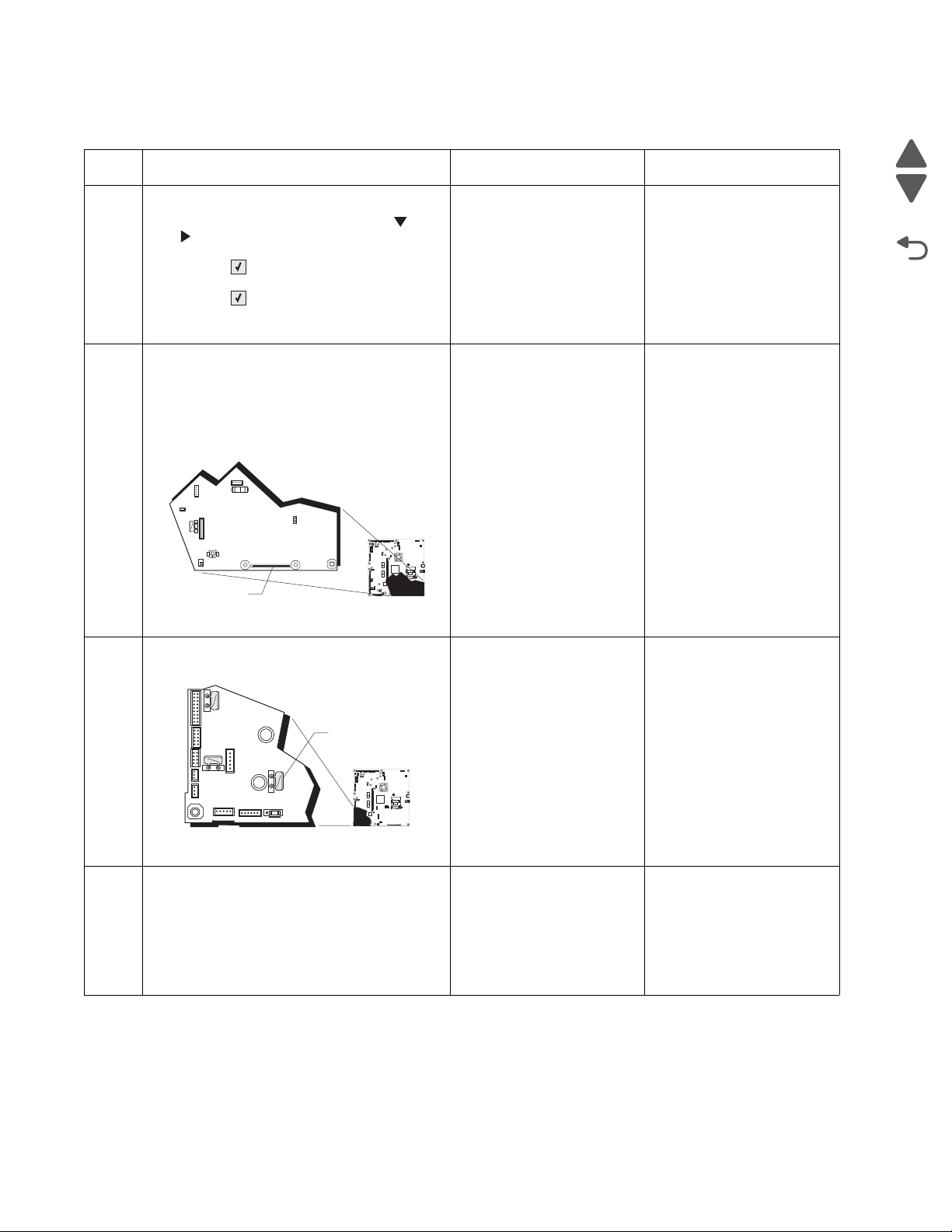
5026
Go Back
Previous
Next
1
JSB1
JBIN1
JFAN1
JFUSER1
JBOR1
JHVPS1
JMIRR1
JBLW1JBLW1
JCVR1
JLVPS2
JCARTP1
JCARTS1
JCARTS2
JCARTP2
JDVR1
JTPS1
JOPT1
JFDS1
JINT1
JFDPCK1JTRAY1JSEC1
JDX1
JT12
J5
JDIMM1
JOPP1
JT1
JUSB1
JBOOT1
JFMUSB1
J49
JTWF1
JTDBUG1
1
1
1
1
1
1
1
1
1
1
1
1
1
1
1
1
1
1
1
1
1
1
1
1
1
JTLBT1
JPH1
F5
F6
F7
F9
F10
F12
F13
F14
1
1
J10
1
1
A
1
JSB1
JBIN1
JFAN1
JFUSER1JFUSER1
JBOR1
JHVPS1
JMIRR1
JBLW1
JCVR1JCVR1
JLVPS2
JCARTP1
JCARTS1
JCARTS2
JCARTP2
JDVR1
JTPS1
JOPT1
JFDS1
JINT1
JFDPCK1JFDPCK1JTRAY1JSEC1
JDX1
JT12
J5
JDIMM1
JOPP1
JT1
JUSB1
JBOOT1
JFMUSB1JFMUSB1
J49
JTWF1
JTDBUG1
1
1
1
1
1
1
1
1
1
1
1
1
1
1
1
1
1
1
1
1
1
1
1
1
1
JTLBT1
JPH1
F5
F6
F7
F9
F10
F12
F13
F14
1
1
J10
1
1
A
111.xx, 112.xx, 113.xx, and 114.xx—Printhead error service check
Step Questions / actions Yes No
1 View the Event Log:
1. Turn off the printer, press and hold and
. and turn on the printer
2. Select EVENT LOG, and press
Select ().
3. Select Display Log, and press
Select ().
Has an 111.xx,112.xx, 113.xx, or 114.xx error
occurred three times or more?
Turn the printer off, and then remove the rear
2
frame cover. See “Rear fr am e co ver
removal” on page 4-33. Check the cable in
connector JPH1 (A) (5 V interlock switch
cable) for proper connection to the system
board, the cable for pinch points, and the
cable or connector for any other damage.
Is the cable damaged?
Replace the printhead. See
“Printhead remova l,
installation, and
adjustment” on
page 4-135.
Replace the 5 V interlock
switch. See “5 V interlock
switch cable removal” on
page 4-45.
Go to step 2.
Go to step 3.
Measure the resistance across fuse F13 (A)
3
on the system board.
Is the fuse blown?
Perform the printhead verification to check
4
whether the new printhead solves the
problem. See “Printhead verification” on
page 3-35.
Perform the Servo Laser Test. See “Servo
Laser Test” on page 3-18.
Did the printhead motor pass the test?
Replace the system board.
See “System board
removal” on page 4-153.
Replace the printhead. See
“Printhead remova l,
installation, and
adjustment” on
page 4-135.
Go to step 4.
Replace the system board.
See “System board
removal” on page 4-153.
2-38 Service Manual
Page 75
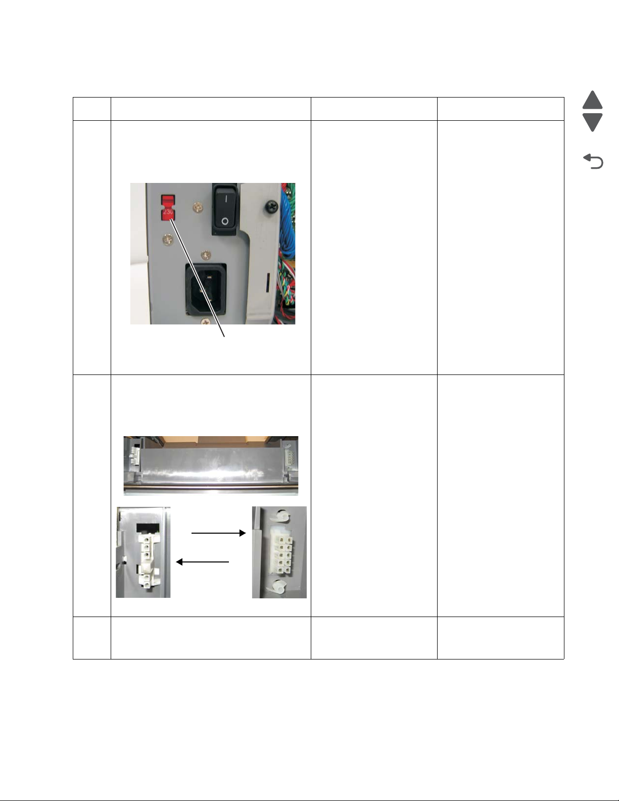
5026
Go Back
Previous
Next
A
230
Fuser autoconnects
DC autoconnect
AC autoconnect
On printer
120.xx—Fuser error service check
Step Questions / actions Yes No
1 Check the input voltage switch on the back of
the low-voltage power supply (LVPS).
Note: Some LVPS FRU do not have switches
and switch automatically. If your does not
have a switch, go to step 2.
Is the voltage level (115 V/230 V) properly
set?
1. Remove the fuser. See “Fuser removal”
2
on page 4-104.
2. Check the AC and DC autoconnects on
both the fuser and the printer for damage.
Go to step 2. Set the switch for the
proper country voltage.
Replace the appropriate
Go to step 3.
cable. See “Fuser AC
cable removal” on
page 4-105 or “Fuser DC
cable removal” on
page 4-106.
Are the connections damaged?
Replace the fuser. See “Fuser removal” on
3
page 4-104.
Does the error clear?
Problem resolved. Go to step 4.
Diagnostic information 2-39
Page 76

5026
Go Back
Previous
Next
1
JSB1
JBIN1
JFAN1
JFUSER1
JBOR1
JHVPS1
JMIRR1
JBLW1
JCVR1
JLVPS2
JCARTP1
JCARTS1
JCARTS2
JCARTP2
JDVR1
JTPS1
JOPT1
JFDS1
JINT1
JFDPCK1JTRAY1JSEC1
JDX1
JT12
J5
JDIMM1
JOPP1
JT1
JUSB1
JBOOT1
JFMUSB1
J49
JTWF1
JTDBUG1
1
1
1
1
1
1
1
1
1
1
1
1
1
1
1
1
1
1
1
1
1
1
1
1
1
JTLBT1
JPH1
F5
F6
F7
F9
F10
F12
F13
F14
1
1
J10
1
1
A
1
JSB1
JBIN1
JFAN1
JFUSER1
JBOR1
JHVPS1
JMIRR1
JBLW1
JCVR1
JLVPS2
JCARTP1
JCARTS1
JCARTS2
JCARTP2
JDVR1
JTPS1
JOPT1
JFDS1
JINT1
JFDPCK1JTRAY1JSEC1
JDX1
JT12
J5
JDIMM1
JOPP1
JT1
JUSB1
JBOOT1
JFMUSB1
J49
JTWF1
JTDBUG1
1
1
1
1
1
1
1
1
1
1
1
1
1
1
1
1
1
1
1
1
1
1
1
1
1
JTLBT1
JPH1
F5
F6
F7
F9
F10
F12
F13
F14
1
1
J10
1
1
A
Step Questions / actions Yes No
Remove the rear frame cover. See“Rear
4
frame cover removal” on page 4-33. Check
the cable in connector JFUSER1 (A) (fuser
DC cable) for proper connection to the system
board, the cable for pinch points, and the
cable or connector for any other damage.
Is the cable damaged?
Check the cable in connector JLVPS2 (A) for
5
proper connection to the system board, the
cable for pinch points, and the cable or
connector for any other damage.
Replace the fuser DC
cable.See “Fuse r DC
cable removal” on
page 4-106.
Replace the LVPS. See
“Low-voltage power
supply (LVPS) removal”
on page 4-112.
Go to step 5.
Go to step 6.
Is the cable damaged?
Measure the resistance across fuse F6 on the
6
system board.
Replace the system board.
See “System board
Go to step 7.
removal” on page 4-153.
Is the fuse blown?
2-40 Service Manual
Page 77
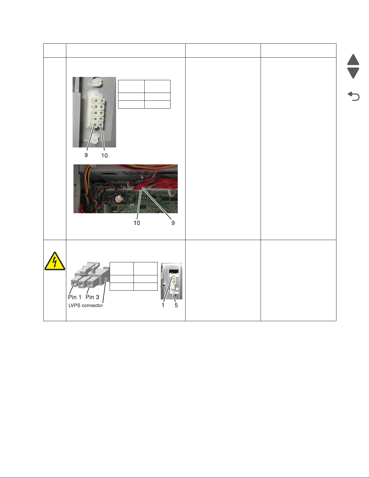
5026
Go Back
Previous
Next
DC autoconnect
JFUSER1
Pin 9 Pin 9
Pin 10 Pin 10
LVPS
connect
AC Autoconnect
Pin 1 Pin 5
Pin 3 Pin 1
Step Questions / actions Yes No
Check for the following continuity between the
7
DC autoconnect JFUSER1 on the system
board.
Is continuity present?
Go to step 8. Replace the fuser DC
cable. See “Fuser DC
cable removal” on
page 4-106.
Check for continuity between the following
8
pins of the AC autoconnect and the pins of
the connector that connects to the LVPS.
Is continuity present?
Replace the system board.
See “System board
removal” on page 4-153.
Replace the fuser AC
cable. See “Fuser AC
cable removal” on
page 4-105.
Diagnostic information 2-41
Page 78
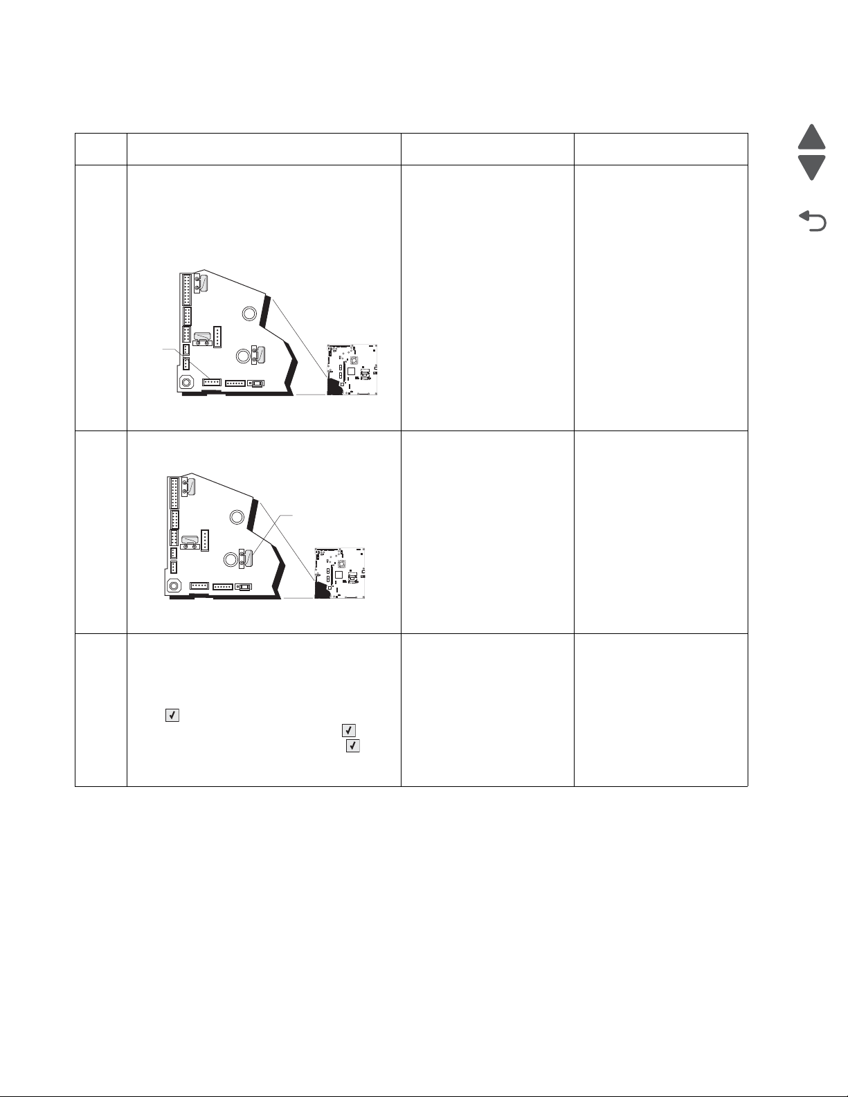
5026
Go Back
Previous
Next
1
JSB1
JBIN1
JFAN1
JFUSER1
JBOR1
JHVPS1
JMIRR1JMIRR1
JBLW1
JCVR1
JLVPS2
JCARTP1
JCARTS1
JCARTS2
JCARTP2
JDVR1
JTPS1
JOPT1
JFDS1
JINT1
JFDPCK1JTRAY1JSEC1
JDX1
JT12
J5
JDIMM1JDIMM1
JOPP1
JT1
JUSB1
JBOOT1
JFMUSB1
J49J49
JTWF1
JTDBUG1
1
1
1
1
1
1
1
1
1
1
1
1
1
1
1
1
1
1
1
1
1
1
1
1
1
JTLBT1
JPH1
F5
F6
F7
F9
F10
F12
F13
F14
1
1
J10
1
1
A
1
JSB1
JBIN1
JFAN1
JFUSER1JFUSER1
JBOR1
JHVPS1
JMIRR1
JBLW1
JCVR1JCVR1
JLVPS2
JCARTP1
JCARTS1
JCARTS2
JCARTP2
JDVR1
JTPS1
JOPT1
JFDS1
JINT1
JFDPCK1JFDPCK1JTRAY1JSEC1
JDX1
JT12
J5
JDIMM1
JOPP1
JT1
JUSB1
JBOOT1
JFMUSB1JFMUSB1
J49
JTWF1
JTDBUG1
1
1
1
1
1
1
1
1
1
1
1
1
1
1
1
1
1
1
1
1
1
1
1
1
1
JTLBT1
JPH1
F5
F6
F7
F9
F10
F12
F13
F14
1
1
J10
1
1
A
140.xx, 920.02—Autocomp (tray 1) motor error service check
Step Questions / actions Yes No
1 Turn the printer off, and then remove the rear
frame cover. See “Rear fr am e co ver
removal” on page 4-33. Check the cable in
connector JFDPCK1 (A) for proper
connection to the system board, the cable for
pinch points, and the cable or connector for
any other damage.
Is the cable damaged?
Measure the resistance across fuse F13 on
2
the system board.
Replace the paper pick
mechanism. See “Paper
pick mechanism
assembly removal” on
page 4-127.
Replace the system board.
See “System board
removal” on page 4-153.
Go to step 2.
Go to step 3.
Is the fuse blown?
1. Disconnect the cable in the connector
3
JFDPCK1.
2. Connect the cable for the new paper pick
mechanism.
3. Select PRINT TESTS, and press Select
( ).
4. Select Tray 1 and press Select ( ).
5. Select Single, and press Select ( ).
Does the new pick motor turn before the feed
error occurred?
2-42 Service Manual
Replace the paper pick
mechanism. See “Paper
pick mechanism
Replace the system board.
See “System board
removal” on page 4-153.
assembly removal” on
page 4-127.
Page 79
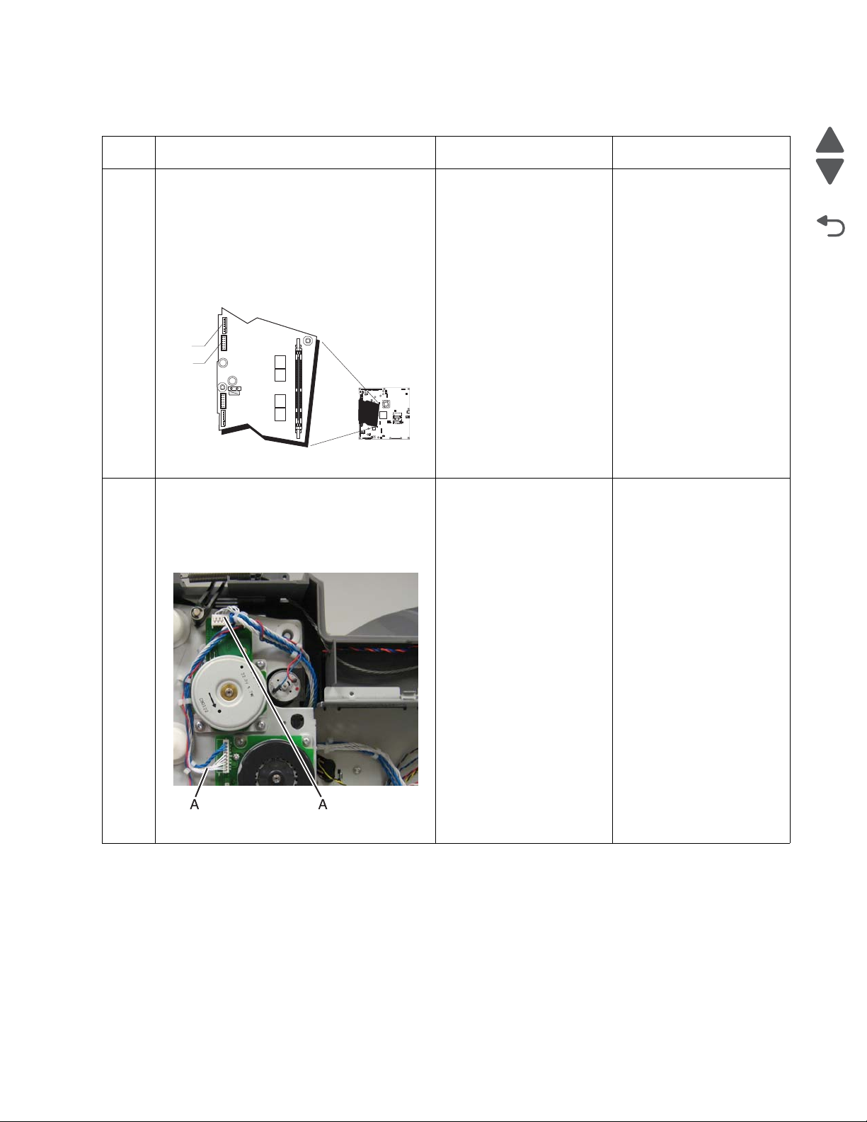
5026
Go Back
Previous
Next
1
JSB1
JBIN1
JFAN1
JFUSER1
JBOR1
JHVPS1
JMIRR1
JBLW1
JCVR1
JLVPS2
JCARTP1
JCARTS1
JCARTS2
JCARTP2
JDVR1JDVR1
JTPS1
JOPT1
JFDS1
JINT1JINT1
JFDPCK1JTRAY1JSEC1
JDX1
JT12
J5
JDIMM1
JOPP1
JT1
JUSB1
JBOOT1
JFMUSB1
J49
JTWF1
JTDBUG1
1
1
1
1
1
1
1
1
1
1
1
1
1
1
1
1
1
1
1
1
1
1
1
1
1
JTLBT1
JPH1
F5
F6
F7
F9
F10
F12
F13
F14
1
1
J10
1
1
A
B
142.xx, 906.01–906.04—Motor (fuser) error service check
Step Questions / actions Yes No
1 1. Turn the printer off.
2. Remove the rear frame cover. See “Rear
frame cover removal” on page 4-33.
3. Check the cables in connectors JCARTP1
(A) and JCARTS1 (B) (cartridge motor 1/
fuser motor cable) for proper connection
to the system board, for cable pinch
points, and for any other damage to the
cable or connectors.
Is either cable damaged?
Remove the right cover. See “Right cover
2
removal” on page 4-37. Check the cartridge
motor 1/fuser motor cable for proper
connection to the EP drive assembly (A), for
pinch points for the cable, and for cable or
connector damage.
Replace the cartridge
motor1/fuser motor cable.
See “Cartridge motor 1/
fuser cable removal ” on
page 4-62.
Replace the cartridge
motor 1/fuser motor cable.
See “Cartridge motor 1/
fuser cable removal ” on
page 4-62.
Go to step 2.
Go to step 3.
Is either cable damaged?
Diagnostic information 2-43
Page 80

5026
Go Back
Previous
Next
1
JSB1
JBIN1
JFAN1
JFUSER1
JBOR1
JHVPS1
JMIRR1
JBLW1
JCVR1
JLVPS2
JCARTP1
JCARTS1
JCARTS2
JCARTP2
JDVR1
JTPS1
JOPT1
JFDS1
JINT1
JFDPCK1JTRAY1JSEC1
JDX1
JT12
J5
JDIMM1
JOPP1
JT1
JUSB1
JBOOT1
JFMUSB1
J49
JTWF1
JTDBUG1
1
1
1
1
1
1
1
1
1
1
1
1
1
1
1
1
1
1
1
1
1
1
1
1
1
JTLBT1
JPH1
F5
F6
F7
F9
F10
F12
F13
F14
1
1
J10
1
1
A
1
JSB1
JBIN1
JFAN1
JFUSER1
JBOR1
JHVPS1
JMIRR1
JBLW1
JCVR1
JLVPS2
JCARTP1
JCARTS1
JCARTS2
JCARTP2
JDVR1
JTPS1
JOPT1
JFDS1
JINT1
JFDPCK1JTRAY1JSEC1
JDX1
JT12
J5
JDIMM1
JOPP1
JT1
JUSB1
JBOOT1
JFMUSB1
J49
JTWF1
JTDBUG1
1
1
1
1
1
1
1
1
1
1
1
1
1
1
1
1
1
1
1
1
1
1
1
1
1
JTLBT1
JPH1
F5
F6
F7
F9
F10
F12
F13
F14
1
1
J10
1
1
A
B
Step Questions / actions Yes No
Measure the resistance across fuse F6 (A) on
3
the system board.
Replace the system board.
See “System board
removal” on page 4-153.
Replace the EP drive
assembly. See
“Electrophotographic
(EP) drive assembly
removal” on page 4-82.
Is the fuser blown?
143.xx—Motor (EP drive assembly top cartridge 1 motor) error service check
Step Questions / actions Yes No
1 1. Turn the printer off.
2. Remove the rear frame cover. See “Rear
frame cover removal” on page 4-33.
3. Check the cable in connector JCARTP1
(A) and JCARTS1 (B) (cartridge motor 1/
fuser motor cable) for proper connection
to the system board, for the cable for
pinch points, and for the cable or
connector for any other damage.
Replace the cartridge
motor 1/fuser cable. See
“Cartridge motor 1/fuser
cable removal” on
page 4-62.
Go to step 2.
Is the cable damaged?
2-44 Service Manual
Page 81
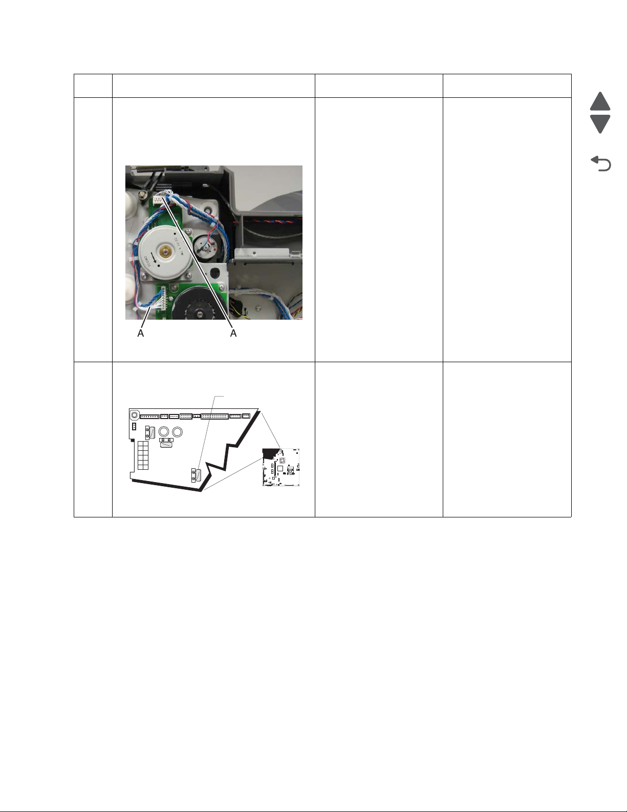
5026
Go Back
Previous
Next
1
JSB1
JBIN1
JFAN1
JFUSER1
JBOR1
JHVPS1
JMIRR1
JBLW1
JCVR1JCVR1
JLVPS2
JCARTP1
JCARTS1
JCARTS2
JCARTP2
JDVR1
JTPS1
JOPT1
JFDS1
JINT1
JFDPCK1JTRAY1JSEC1
JDX1
JT12
J5
JDIMM1
JOPP1
JT1
JUSB1
JBOOT1
JFMUSB1
J49
JTWF1
JTDBUG1
1
1
1
1
1
1
1
1
1
1
1
1
1
1
1
1
1
1
1
1
1
1
1
1
1
JTLBT1
JPH1
F5
F6
F7
F9
F10
F12
F13
F14
1
1
J10
1
1
A
Step Questions / actions Yes No
Remove the right cover. See “Right cover
2
removal” on page 4-37. Check the cartridge
motor 1/fuser motor cable (A0 for proper
connection to the EP drive assembly, for
pinch points for the cable, or damage to the
cable or connector.
Is either cable damaged?
Measure the resistance across fuse F7 on the
3
system board.
Replace the cartridge
motor 1/fuser motor cable.
See “Cartridge motor 1/
fuser cable removal ” on
page 4-62.
Replace the system board.
See “System board
removal” on page 4-153.
Go to step 3.
Replace the EP drive
assembly. See
“Electrophotographic
(EP) drive assembly
removal” on page 4-82.
Is the fuse blown?
Diagnostic information 2-45
Page 82

5026
Go Back
Previous
Next
1
JSB1
JBIN1
JFAN1
JFUSER1
JBOR1
JHVPS1
JMIRR1
JBLW1
JCVR1
JLVPS2
JCARTP1
JCARTS1
JCARTS2
JCARTP2
JDVR1
JTPS1
JOPT1
JFDS1
JINT1
JFDPCK1JTRAY1JSEC1
JDX1
JT12
J5
JDIMM1
JOPP1
JT1
JUSB1
JBOOT1
JFMUSB1
J49
JTWF1
JTDBUG1
1
1
1
1
1
1
1
1
1
1
1
1
1
1
1
1
1
1
1
1
1
1
1
1
1
JTLBT1
JPH1
F5
F6
F7
F9
F10
F12
F13
F14
1
1
J10
1
1
A
B
144.xx—Motor (EP drive assembly middle cartridge) error service check
Step Questions / actions Yes No
1 1. Turn the printer off.
2. Remove the rear frame cover. See “Rear
frame cover removal” on page 4-33.
3. Check the cables in connector JCARTP2
and JCARTS2 (A) (cartridge motor 2/3
cable) for proper connection to the system
board, for cable pinch points, and for any
other damage to the cable or connector.
Is the cable damaged?
Remove the right cover. See “Right cover
2
removal” on page 4-37. Check the cartridge
motor 2/3 cable for proper connection to the
EP drive assembly, pinch points for the cable,
or damage to the cable or connector (A).
Replace cartridge motor 2/
3 cable. See “Cartridge
motor 2/3 cable removal”
on page 4-64.
Replace the cartridge
motor 2/3 cable. See
“Cartridge motor 2/3
cable removal” on
page 4-64.
Go to step 2.
Go to step 3.
Is either cable damaged?
2-46 Service Manual
Page 83

5026
Go Back
Previous
Next
1
JSB1
JBIN1
JFAN1
JFUSER1
JBOR1
JHVPS1
JMIRR1
JBLW1
JCVR1
JLVPS2
JCARTP1
JCARTS1
JCARTS2
JCARTP2
JDVR1JDVR1
JTPS1
JOPT1
JFDS1
JINT1JINT1
JFDPCK1JTRAY1JSEC1
JDX1
JT12
J5
JDIMM1
JOPP1
JT1
JUSB1
JBOOT1
JFMUSB1
J49
JTWF1
JTDBUG1
1
1
1
1
1
1
1
1
1
1
1
1
1
1
1
1
1
1
1
1
1
1
1
1
1
JTLBT1
JPH1
F5
F6
F7
F9
F10
F12
F13
F14
1
1
J10
1
1
A
1
JSB1
JBIN1
JFAN1
JFUSER1
JBOR1
JHVPS1
JMIRR1
JBLW1
JCVR1
JLVPS2
JCARTP1
JCARTS1
JCARTS2
JCARTP2
JDVR1JDVR1
JTPS1
JOPT1
JFDS1
JINT1JINT1
JFDPCK1JTRAY1JSEC1
JDX1
JT12
J5
JDIMM1
JOPP1
JT1
JUSB1
JBOOT1
JFMUSB1
J49
JTWF1
JTDBUG1
1
1
1
1
1
1
1
1
1
1
1
1
1
1
1
1
1
1
1
1
1
1
1
1
1
JTLBT1
JPH1
F5
F6
F7
F9
F10
F12
F13
F14
1
1
J10
1
1
A
B
Step Questions / actions Yes No
Measure the resistance across fuse F9 on the
3
system board.
Replace the system board.
See “System board
removal” on page 4-153.
Replace the EP drive
assembly. See
“Electrophotographic
(EP) drive assembly
removal” on page 4-82.
Is the fuse blown?
145.xx—Motor (EP drive assembly bottom cartridge) error service check
Step Questions / actions Yes No
1 1. Turn the printer off.
2. Remove the rear frame cover. See “Rear
frame cover removal” on page 4-33.
3. Check the cables in connector JCARTP2
(A) and JCARTS2 (B) (cartridge motor 2/3
cable) for proper connection to the system
board, for cable pinch points, and for any
other damage to the cable or connector.
Replace cartridge motor 2/
3 cable. See “Cartridge
motor 2/3 cable removal”
on page 4-64.
Go to step 2.
Is the cable damaged?
Diagnostic information 2-47
Page 84

5026
Go Back
Previous
Next
1
JSB1
JBIN1
JFAN1
JFUSER1
JBOR1
JHVPS1
JMIRR1
JBLW1
JCVR1
JLVPS2
JCARTP1JCARTP1
JCARTS1JCARTS1
JCARTS2JCARTS2
JCARTP2JCARTP2
JDVR1
JTPS1JTPS1
JOPT1
JFDS1
JINT1JINT1
JFDPCK1JTRAY1JSEC1
JDX1
JT12
J5
JDIMM1
JOPP1
JT1
JUSB1
JBOOT1
JFMUSB1JFMUSB1
J49
JTWF1
JTDBUG1
1
1
1
1
1
1
1
1
1
1
1
1
1
1
1
1
1
1
1
1
1
1
1
1
1
JTLBT1
JPH1
F5
F6
F7
F9
F10
F12
F13
F14
1
1
J10
1
1
A
Step Questions / actions Yes No
Remove the right cover. Check the cartridge
2
motor 2/3 cable for proper connection to the
EP drive assembly, pinch points for the cable,
and damage to the cable or connector (A).
Is either cable damaged?
Measure the resistance across fuse F10 on
3
the system board.
Replace the cartridge
motor 2/3 cable. See
“Cartridge motor 2/3
cable removal” on
page 4-64.
Replace the system board.
See “System board
removal” on page 4-153.
Go to step 3.
Replace the EP drive
assembly. See
“Electrophotographic
(EP) drive assembly
removal” on page 4-82.
Is the fuse blown?
146.xx, 148.xx—Motor (MPF/duplex) error service check
Step Questions / actions Yes No
1 Is the front door assembly damaged? Replace the front door
assembly. See “Front
door assembly removal”
on page 4-93.
2-48 Service Manual
Go to step 2.
Page 85

5026
Go Back
Previous
Next
1
JSB1
JBIN1
JFAN1
JFUSER1
JBOR1
JHVPS1
JMIRR1
JBLW1
JCVR1
JLVPS2
JCARTP1
JCARTS1
JCARTS2
JCARTP2
JDVR1
JTPS1
JOPT1
JFDS1
JINT1JINT1
JFDPCK1JTRAY1JSEC1
JDX1
JT12
J5
JDIMM1
JOPP1
JT1
JUSB1
JBOOT1
JFMUSB1
J49
JTWF1
JTDBUG1
1
1
1
1
1
1
1
1
1
1
1
1
1
1
1
1
1
1
1
1
1
1
1
1
1
JTLBT1JTLBT1
JPH1
F5
F6
F7
F9
F10
F12
F13
F14
1
1
J10
1
1
A
Step Questions / actions Yes No
Is the multipurpose feeder damaged? Replace input tray. Go to step 3.
2
1. Turn the printer off.
3
2. Remove the rear frame cover. See “Rear
frame cover removal” on page 4-33.
3. Check the cable in connector JDX1 (A)
(MP feeder/duplex motor cable) for proper
connection to the system board, the cable
for pinch points, and the cable or
connector for any other damage.
Is the cable damaged?
Remove the right cover. See “Right cover
4
removal” on page 4-37. Check the MP
feeder/duplex motor cable for proper
connection to the MPF/duplex motor, pinch
points for the cable, and damage to the cable
or connector.
Replace the MPF/duplex
motor cable. See
“Multipurpose feeder
(MPF)/duplex motor
cable removal” on
page 4-121.
Replace the MPF/duplex
motor cable. See
“Multipurpose feeder
(MPF)/duplex motor
cable removal” on
page 4-121.
Go to step 4.
Go to step 5.
Is either cable damaged?
Diagnostic information 2-49
Page 86
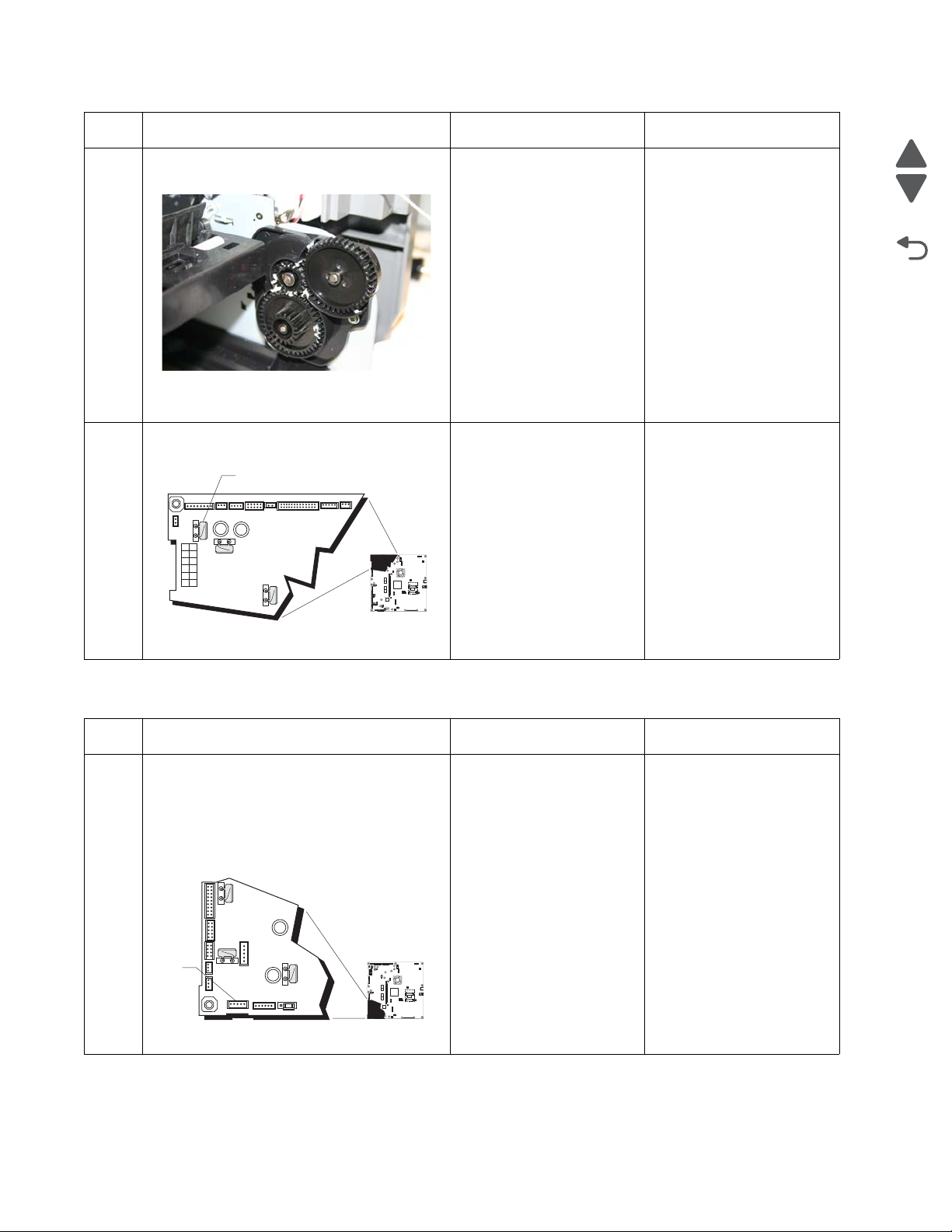
5026
Go Back
Previous
Next
1
JSB1
JBIN1
JFAN1
JFUSER1
JBOR1
JHVPS1
JMIRR1
JBLW1
JCVR1
JLVPS2
JCARTP1
JCARTS1
JCARTS2
JCARTP2
JDVR1
JTPS1
JOPT1
JFDS1
JINT1
JFDPCK1JTRAY1JSEC1
JDX1
JT12
J5
JDIMM1
JOPP1
JT1
JUSB1
JBOOT1
JFMUSB1
J49
JTWF1
JTDBUG1
1
1
1
1
1
1
1
1
1
1
1
1
1
1
1
1
1
1
1
1
1
1
1
1
1
JTLBT1
JPH1
F5
F6
F7
F9
F10
F12
F13
F14
1
1
J10
1
1
A
1
JSB1
JBIN1
JFAN1
JFUSER1
JBOR1
JHVPS1
JMIRR1JMIRR1
JBLW1
JCVR1
JLVPS2
JCARTP1
JCARTS1
JCARTS2
JCARTP2
JDVR1
JTPS1
JOPT1
JFDS1
JINT1
JFDPCK1JTRAY1JSEC1
JDX1
JT12
J5
JDIMM1JDIMM1
JOPP1
JT1
JUSB1
JBOOT1
JFMUSB1
J49J49
JTWF1
JTDBUG1
1
1
1
1
1
1
1
1
1
1
1
1
1
1
1
1
1
1
1
1
1
1
1
1
1
JTLBT1
JPH1
F5
F6
F7
F9
F10
F12
F13
F14
1
1
J10
1
1
A
Step Questions / actions Yes No
Check the MPF/duplex gear assembly for
5
damage.
Do the gears turn freely, and are they free of
damage?
Measure the resistance across fuse F5 (A) on
6
the system board.
Go to step 6. Replace the MPF/duplex
gear assembly. See
“Multipurpose feeder
(MPF)/duplex gear and
housing removal” on
page 4-116.
Replace the system board.
See “System board
removal” on page 4-153.
Replace the MPF/duplex
motor. See “Multipurpose
feeder (MPF)/duplex
motor assembly
removal” on page 4-118.
Is the fuse blown?
147.xx, 920.01—POST (power-on self test) aligner error service check
Step Questions / actions Yes No
1 1. Turn the printer off.
2. Remove the rear frame cover. See “Rear
frame cover removal” on page 4-33.
3. Check the cable in connector JFPCK1 for
proper connection to the system board,
Replace the paper pick
mechanism. See “Paper
pick mechanism
assembly removal” on
page 4-127.
the cable for pinch points, and the cable or
connector for any other damage.
Is the cable damaged?
Go to step 2.
2-50 Service Manual
Page 87

5026
Go Back
Previous
Next
1
JSB1
JBIN1
JFAN1
JFUSER1
JBOR1
JHVPS1
JMIRR1
JBLW1
JCVR1JCVR1
JLVPS2JLVPS2
JCARTP1
JCARTS1
JCARTS2
JCARTP2
JDVR1
JTPS1
JOPT1
JFDS1
JINT1
JFDPCK1JTRAY1JSEC1
JDX1
JT12
J5
JDIMM1
JOPP1JOPP1
JT1
JUSB1
JBOOT1
JFMUSB1
J49
JTWF1
JTDBUG1
1
1
1
1
1
1
1
1
1
1
1
1
1
1
1
1
1
1
1
1
1
1
1
1
1
JTLBT1
JPH1
F5
F6
F7
F9
F10
F12
F13
F14
1
1
J10
1
1
A
Step Questions / actions Yes No
Check the cable in the connector JFDPCK1
2
for pinch points and for any other damage to
the cable or connector.
Is the cable damaged?
1. Disconnect the cable in connector
3
JFDPCK1 and connect the cable from the
new paper pick mechanism to JFDPCK1.
2. Bring the printer up in Diagnostics Menu
(turn off the printer, press and hold and
Replace paper pick
mechanism. See “Paper
pick mechanism
assembly removal” on
page 4-127.
Replace the paper pick
mechanism. See “Paper
pick mechanism
assembly removal” on
page 4-127.
Go to step 3.
Replace the system board.
See “System board
removal” on page 4-153.
. and turn on the printer).
3. Select MOTOR TESTS, and press Select
( ).
4. Close the front cover.
5. Select Align Motor Test, and press
Select ( ).
Did you hear the align motor run?
155.xx—Cam motor error service check
Step Questions / actions Yes No
1 1. Turn the printer off.
2. Remove the rear frame cover. See “Rear
frame cover removal” on page 4-33.
3. Check the motor driver cable in connector
JDVR1 on the system board for proper
connection, for cable pinch points, and for
any other damage to the cable or
connector.
Replace the motor driver
cable. See “Motor driver
cable removal” on
page 4-115.
Go to step 2.
Is the cable damaged?
Remove the right cover. See “Right cover
2
removal” on page 4-37. Check the motor
driver cable for proper connection to the EP
drive assembly, pinch points for the cable,
and damage for the cable or connector.[
Is either cable damaged?
Replace the motor driver
cable. See “Motor driver
cable removal” on
page 4-115.
Go to step 3.
Diagnostic information 2-51
Page 88

5026
Go Back
Previous
Next
Step Questions / actions Yes No
Check the transport motor cable from the cam
3
motor to the motor driver card for poor
connections or damage.
Is the cable damaged?
Measure the resistance across fuses F12 (A)
4
and F13 (B) on the system board.
Replace the transport
motor cable. See
“Transport cable
removal” on page 4-170.
Replace the system board.
See “System board
removal” on page 4-153.
Go to step 4.
Go to step 5.
Is either fuse blown?
Visually inspect the motor driver card.
5
Is the motor driver card damaged?
Replace the motor driver
card. See “Motor driver
cable removal” on
page 4-115.
Replace the EP drive
assembly. See
“Electrophotographic
(EP) drive assembly
removal” on page 4-82.
2-52 Service Manual
Page 89
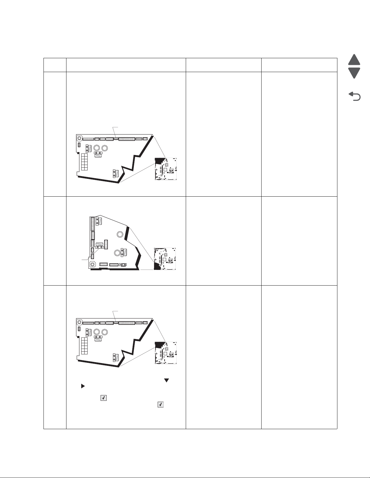
5026
Go Back
Previous
Next
1
JSB1
JBIN1
JFAN1
JFUSER1
JBOR1
JHVPS1
JMIRR1
JBLW1
JCVR1JCVR1
JLVPS2
JCARTP1
JCARTS1
JCARTS2
JCARTP2
JDVR1
JTPS1
JOPT1
JFDS1
JINT1
JFDPCK1JTRAY1JSEC1
JDX1
JT12
J5
JDIMM1
JOPP1
JT1
JUSB1
JBOOT1
JFMUSB1
J49
JTWF1
JTDBUG1
1
1
1
1
1
1
1
1
1
1
1
1
1
1
1
1
1
1
1
1
1
1
1
1
1
JTLBT1
JPH1
F5
F6
F7
F9
F10
F12
F13
F14
1
1
J10
1
1
A
1
JSB1
JBIN1
JFAN1
JFUSER1
JBOR1
JHVPS1
JMIRR1
JBLW1
JCVR1
JLVPS2
JCARTP1
JCARTS1
JCARTS2
JCARTP2
JDVR1
JTPS1
JOPT1
JFDS1
JINT1JINT1
JFDPCK1JTRAY1JSEC1
JDX1
JT12
J5
JDIMM1
JOPP1
JT1
JUSB1
JBOOT1
JFMUSB1
J49
JTWF1
JTDBUG1
1
1
1
1
1
1
1
1
1
1
1
1
1
1
1
1
1
1
1
1
1
1
1
1
1
JTLBT1JTLBT1
JPH1
F5
F6
F7
F9
F10
F12
F13
F14
1
1
J10
1
1
A
1
JSB1
JBIN1
JFAN1
JFUSER1
JBOR1
JHVPS1
JMIRR1
JBLW1
JCVR1JCVR1
JLVPS2
JCARTP1
JCARTS1
JCARTS2
JCARTP2
JDVR1
JTPS1
JOPT1
JFDS1
JINT1
JFDPCK1JTRAY1JSEC1
JDX1
JT12
J5
JDIMM1
JOPP1
JT1
JUSB1
JBOOT1
JFMUSB1
J49
JTWF1
JTDBUG1
1
1
1
1
1
1
1
1
1
1
1
1
1
1
1
1
1
1
1
1
1
1
1
1
1
JTLBT1
JPH1
F5
F6
F7
F9
F10
F12
F13
F14
1
1
J10
1
1
A
156.xx—COD (Color On Demand) motor service check
Step Questions / actions Yes No
1 1. Turn the printer off.
2. Remove the rear frame cover. See “Rear
frame cover removal” on page 4-33.
3. Check the cable in connector JBOR1 (A)
on the system board for proper
connection, for cable pinch points, and for
any other damage to the cable or
connector.
Is the cable damaged?
Measure the resistance across fuse F12(A)
2
on the system board.
Replace the COD
assembly. See “Color on
demand assembly
removal” on page 4-66.
Replace the system board.
See “System board
removal” on page 4-153.
Go to step 2.
Go to step 3.
Is the fuse blown?
1. Disconnect the cable in connector JBOR1
3
(A), and then connect the cable from the
new COD group assembly.
Replace the COD
assembly. See “Color on
demand assembly
Replace the system board.
See “System board
removal” on page 4-153.
removal” on page 4-66.
2. Bring the printer up in Diagnostics Menu
(turn off the printer, press and hold and
. and turn on the printer).
3. Select MOTOR TESTS, and press
Select ().
4. Select COD, and press Select ().
5. Select Forward. If nothing happens,
Select Reverse.
Did the COD motor pass the test?
Diagnostic information 2-53
Page 90
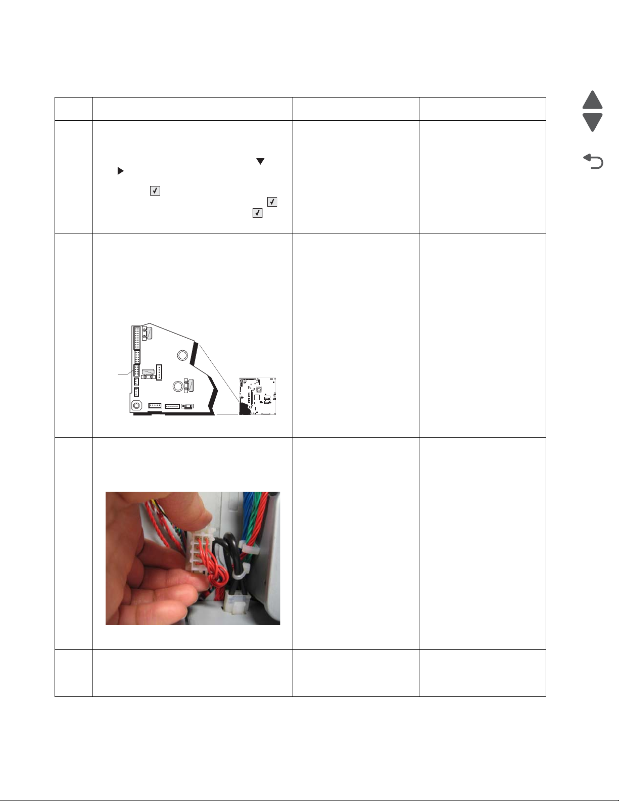
5026
Go Back
Previous
Next
1
JSB1
JBIN1
JFAN1
JFUSER1
JBOR1
JHVPS1
JMIRR1
JBLW1
JCVR1
JLVPS2
JCARTP1
JCARTS1
JCARTS2
JCARTP2
JDVR1
JTPS1
JOPT1
JFDS1
JINT1
JFDPCK1JTRAY1JSEC1
JDX1
JT12
J5
JDIMM1
JOPP1
JT1
JUSB1
JBOOT1
JFMUSB1
J49
JTWF1
JTDBUG1
1
1
1
1
1
1
1
1
1
1
1
1
1
1
1
1
1
1
1
1
1
1
1
1
1
JTLBT1
JPH1
F5
F6
F7
F9
F10
F12
F13
F14
1
1
J10
1
1
A
160.xx, 161.xx—Motor Error (option tray 2) service check
Step Questions / actions Yes No
1 1. Turn the printer off.
2. Reseat option tray 2.
3. Bring the printer up in Diagnostics Menu
(turn off the printer, press and hold and
. and turn on the printer).
4. Select PRINT TESTS, and press
Select ().
5. Select the Tray 2, and press Select ().
6. Select Single, and press Select ().
Did the page print?
1. Turn the printer off.
2
2. Remove the rear frame cover. See “Rear
frame cover removal” on page 4-33.
3. Check the option cable in connector
JOPT1 (A) on the system board for proper
connection, for cable pinch points, and for
any other damage to the cable or
connector
Problem resolved. Go to step 2.
Replace the option cable.
Go to step 3.
See “Option cable
removal” on page 4-125.
Is the cable damaged?
Remove the right cover. See “Right cover
3
removal” on page 4-37.
Check the option cable for pinch points and
any damage.
Is the cable damaged?
Is the option tray 2 the high-capacity input tray
4
(2,000-sheet feeder)?
Replace the option cable.
See “Option cable
removal” on page 4-125.
Replace the HCIT top plate
assembly. See “Top plate
assembly removal” on
page 4-204.
Go to step 4.
Replace the option tray 2
assembly.
2-54 Service Manual
Page 91
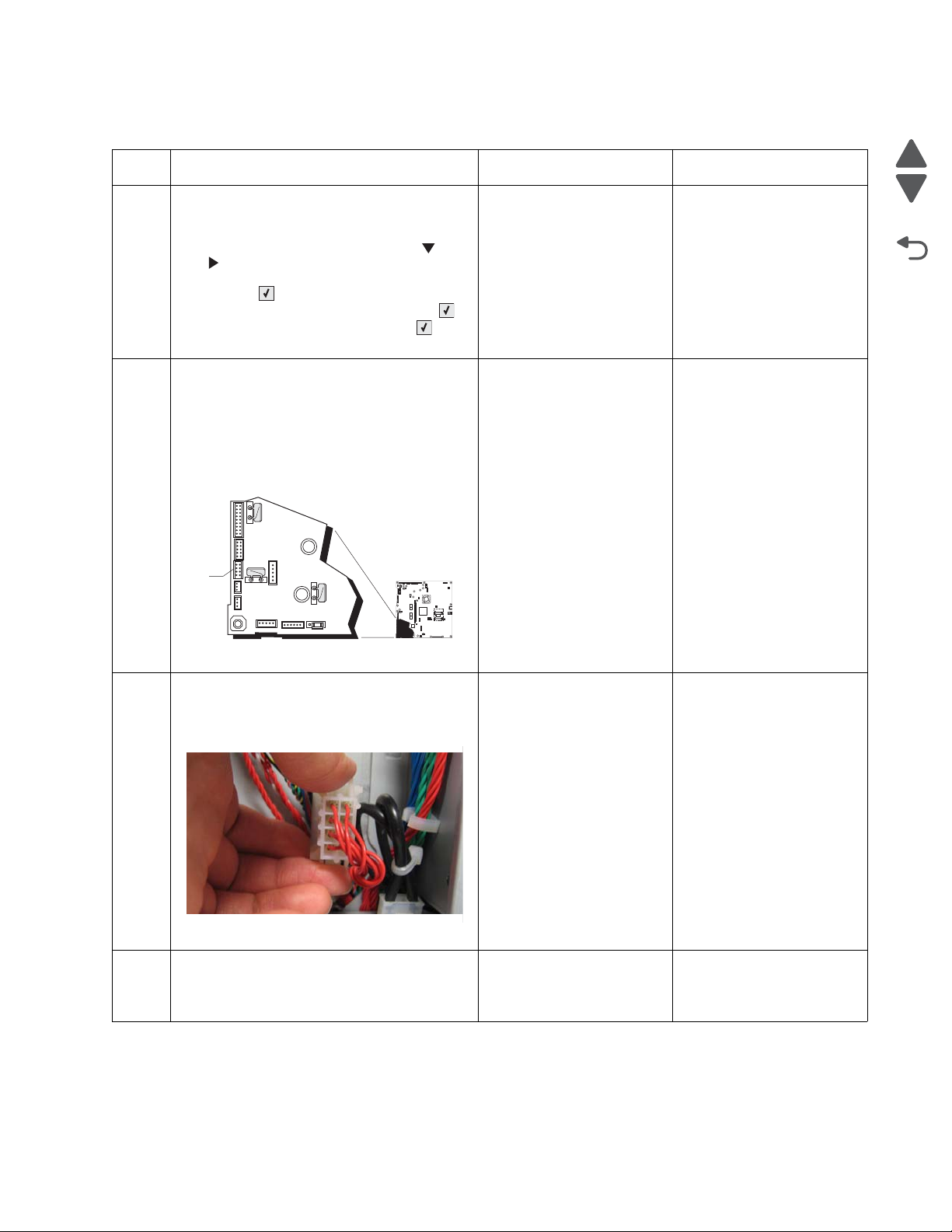
5026
Go Back
Previous
Next
1
JSB1
JBIN1
JFAN1
JFUSER1
JBOR1
JHVPS1
JMIRR1
JBLW1
JCVR1
JLVPS2
JCARTP1
JCARTS1
JCARTS2
JCARTP2
JDVR1
JTPS1
JOPT1
JFDS1
JINT1JINT1
JFDPCK1JTRAY1JSEC1
JDX1
JT12
J5
JDIMM1
JOPP1
JT1
JUSB1
JBOOT1
JFMUSB1
J49
JTWF1
JTDBUG1
1
1
1
1
1
1
1
1
1
1
1
1
1
1
1
1
1
1
1
1
1
1
1
1
1
JTLBT1JTLBT1
JPH1
F5
F6
F7
F9
F10
F12
F13
F14
1
1
J10
1
1
A
162.xx, 163.xx—Motor Error (option tray 3) service check
Step Questions / actions Yes No
1 1. Turn the printer off.
2. Reseat option tray 3.
3. Bring the printer up in Diagnostics Menu
(turn off the printer, press and hold and
. and turn on the printer).
4. Select PRINT TESTS, and press
Select ().
5. Select the Tray 3, and press Select ().
6. Select Single, and press Select ().
Did the page print?
1. Turn the printer off.
2
2. Remove the rear frame cover. See “Rear
frame cover removal” on page 4-33.
3. Check the option cable in connector
JOPT1 (A) on the system board for proper
connection, for cable pinch points, and for
any other damage to the cable or
connector
Problem resolved. Go to step 2.
Replace the option cable.
Go to step 3.
See “Option cable
removal” on page 4-125.
Is the cable damaged?
Remove the right cover. See “Right cover
3
removal” on page 4-37.
Check the option cable for pinch points and
any damage.
Is the cable damaged?
Is the option tray 3 the high-capacity input tray
4
(2,000-sheet feeder)?
Replace the option cable.
See “Option cable
removal” on page 4-125.
Replace the HCIT top plate
assembly. See “Top plate
assembly removal” on
page 4-204.
Go to step 4
Replace the option tray 3
assembly.
Diagnostic information 2-55
Page 92

5026
Go Back
Previous
Next
1
JSB1
JBIN1
JFAN1
JFUSER1
JBOR1
JHVPS1
JMIRR1
JBLW1
JCVR1
JLVPS2
JCARTP1
JCARTS1
JCARTS2
JCARTP2
JDVR1
JTPS1
JOPT1
JFDS1
JINT1
JFDPCK1JTRAY1JSEC1
JDX1
JT12
J5
JDIMM1
JOPP1
JT1
JUSB1
JBOOT1
JFMUSB1
J49
JTWF1
JTDBUG1
1
1
1
1
1
1
1
1
1
1
1
1
1
1
1
1
1
1
1
1
1
1
1
1
1
JTLBT1
JPH1
F5
F6
F7
F9
F10
F12
F13
F14
1
1
J10
1
1
A
164.xx, 165.xx—Motor Error (option tray 4) service check
Step Questions / actions Yes No
1 1. Turn the printer off.
2. Reseat option tray 4.
3. Bring the printer up in Diagnostics Menu
(turn off the printer, press and hold and
. and turn on the printer).
4. Select PRINT TESTS, and press
Select ().
5. Select the Tray 4, and press Select ().
6. Select Single, and press Select ().
Did the page print?
Turn the printer off, and then remove the rear
2
frame cover. See “Rear fr am e co ver
removal” on page 4-33.
Check the option cable in connector
JOPT1 (A) on the system board for proper
connection, for cable pinch points, and for any
other damage to the cable or connector
Is the cable damaged?
Problem resolved. Go to step 2.
Replace the option cable.
Go to step 3.
See “Option cable
removal” on page 4-125.
Remove the right cover. See “Right cover
3
removal” on page 4-37.
Check the option cable for pinch points and
any damage.
Is the cable damaged?
Is the option tray 4 the high-capacity input tray
4
(2,000-sheet feeder)?
Replace the option cable.
See “Option cable
removal” on page 4-125.
Replace the HCIT top plate
assembly. See “Top plate
assembly removal” on
page 4-204.
Go to step 4.
Replace the option tray 4
assembly.
2-56 Service Manual
Page 93
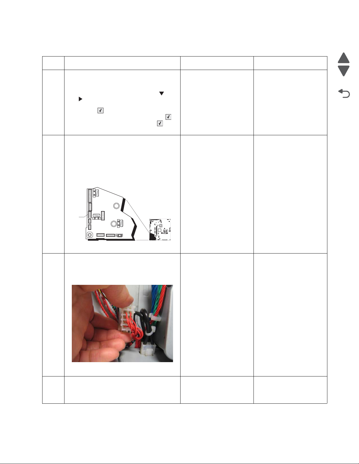
5026
Go Back
Previous
Next
1
JSB1
JBIN1
JFAN1
JFUSER1
JBOR1
JHVPS1
JMIRR1
JBLW1
JCVR1
JLVPS2
JCARTP1
JCARTS1
JCARTS2
JCARTP2
JDVR1
JTPS1
JOPT1
JFDS1
JINT1JINT1
JFDPCK1JTRAY1JSEC1
JDX1
JT12
J5
JDIMM1
JOPP1
JT1
JUSB1
JBOOT1
JFMUSB1
J49
JTWF1
JTDBUG1
1
1
1
1
1
1
1
1
1
1
1
1
1
1
1
1
1
1
1
1
1
1
1
1
1
JTLBT1JTLBT1
JPH1
F5
F6
F7
F9
F10
F12
F13
F14
1
1
J10
1
1
A
166.xx, 167.xx—Motor Error (option tray 5) service check
Step Questions / actions Yes No
1 1. Turn the printer off.
2. Reseat option tray 5.
3. Bring the printer up in Diagnostics Menu
(turn off the printer, press and hold and
. and turn on the printer).
4. Select PRINT TESTS, and press
Select ().
5. Select the Tray 5, and press Select ().
6. Select Single, and press Select ().
Did the page print?
1. Turn the printer off.
2
2. Remove the rear frame cover. See “Rear
frame cover removal” on page 4-33.
3. Check the option cable in connector
JOPT1 (A) on the system board for proper
connection, for cable pinch points, and for
any other damage to the cable or
connector
Problem resolved. Go to step 2.
Replace the option cable.
Go to step 3.
See “Option cable
removal” on page 4-125.
Is the cable damaged?
Remove the right cover. See “Right cover
3
removal” on page 4-37.
Check the option cable for pinch points and
any damage.
Is the cable damaged?
Is the option tray 5 the high-capacity input tray
4
(2,000-sheet feeder)?
Replace the option cable.
See “Option cable
removal” on page 4-125.
Replace the HCIT top plate
assembly. See “Top plate
assembly removal” on
page 4-204.
Go to step 4
Replace the option tray 5
assembly.
Diagnostic information 2-57
Page 94
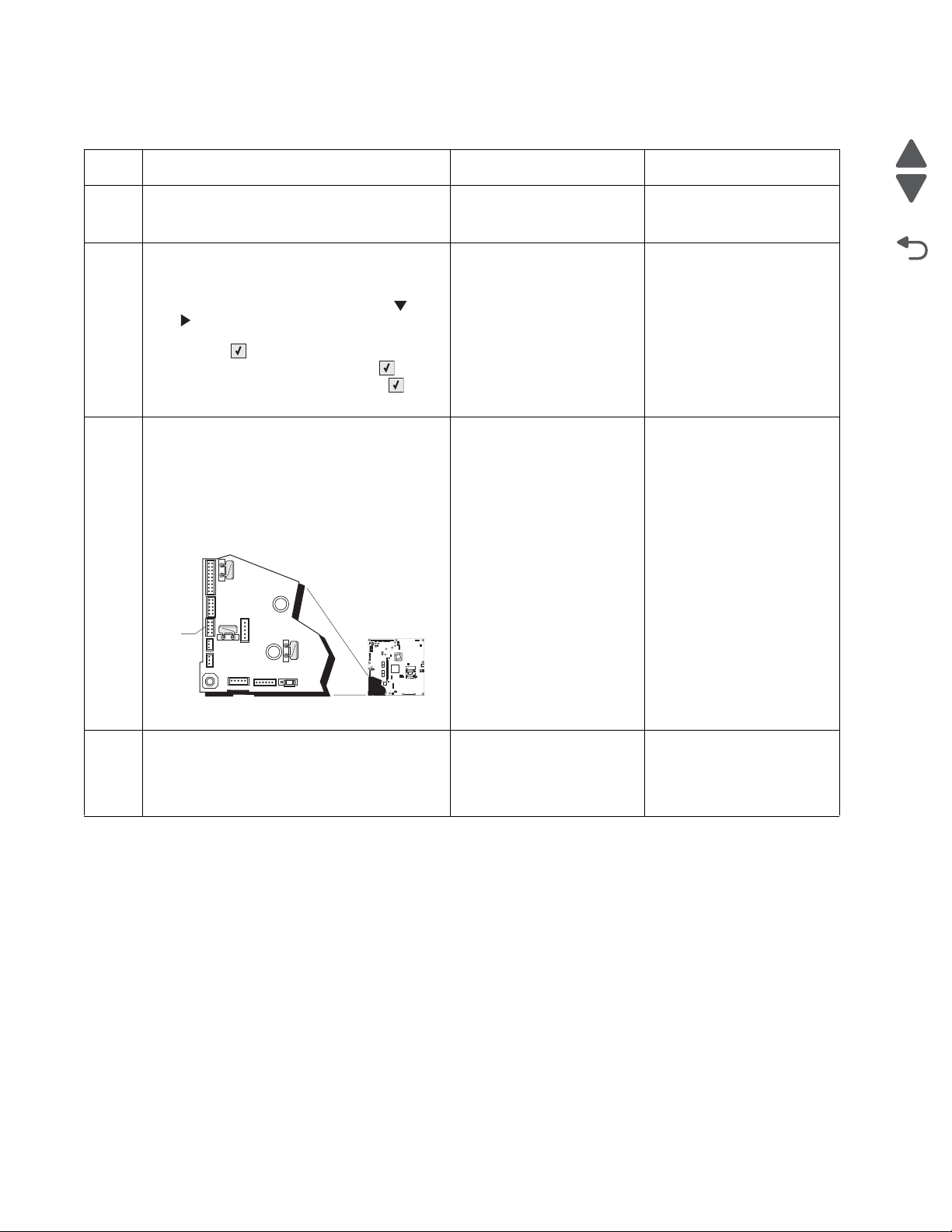
5026
Go Back
Previous
Next
1
JSB1
JBIN1
JFAN1
JFUSER1
JBOR1
JHVPS1
JMIRR1
JBLW1
JCVR1
JLVPS2
JCARTP1
JCARTS1
JCARTS2
JCARTP2
JDVR1
JTPS1
JOPT1
JFDS1
JINT1
JFDPCK1JTRAY1JSEC1
JDX1
JT12
J5
JDIMM1
JOPP1
JT1
JUSB1
JBOOT1
JFMUSB1
J49
JTWF1
JTDBUG1
1
1
1
1
1
1
1
1
1
1
1
1
1
1
1
1
1
1
1
1
1
1
1
1
1
JTLBT1
JPH1
F5
F6
F7
F9
F10
F12
F13
F14
1
1
J10
1
1
A
168.xx—Motor (HCIT elevator) error service check
Step Questions / actions Yes No
1 Is the paper properly loaded in the high-
capacity input tray (HCIT)?
1. Turn the printer off.
2
2. Reseat option the HCIT option.
3. Bring the printer up in Diagnostics Menu
(turn off the printer, press and hold and
. and turn on the printer).
4. Select PRINT TESTS, and press
Select ().
5. Select HCIT, and press Select ().
6. Select Single, and press Select ().
Did the error clear?
1. Turn the printer off.
3
2. ,Remove the rear frame cover. See “Rear
frame cover removal” on page 4-33.
3. Check the option cable in connector
JOPT1 (A) on the system board for proper
connection, for cable pinch points, and for
any other damage to the cable or
connector
Go to step 2. Fan the media, and then
stack flat in the HCIT
drawer.
Problem resolved. Go to step 3.
Replace the option cable.
Go to step 4.
See “Option cable
removal” on page 4-125.
Is the cable damaged?
Check the cable in the HCIT.
4
Is the cable damaged?
2-58 Service Manual
Replace the elevator-up
cable.
Replace the elevator motor
with sensor. See “HCIT
elevator motor with
sensor removal” on
page 4-198.
Page 95
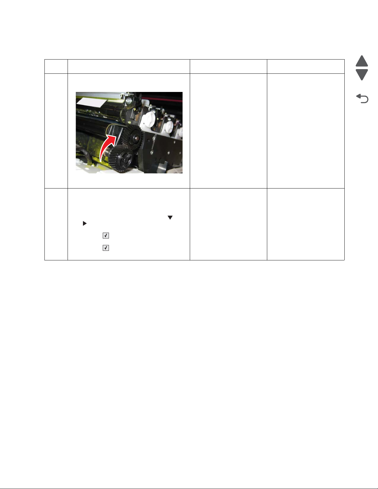
5026
Go Back
Previous
Next
200.11, 250.03—Paper Jam error service check
Step Questions / actions Yes No
1 Open the front access door. Turn the
transport belt gear clockwise.
Did the transport belt move?
1. Disconnect the cable in connector
2
JFDPCK1 and connect the cables for the
new paper pick mechanism.
2. Bring the printer up in Diagnostics Menu
(turn off the printer, press and hold and
. and turn on the printer).
3. Select MOTOR TESTS, and press
Select ().
4. Select Align Motor Test, and press
Select ().
Can you hear the align motor run?
Go to step 2. Replace the transport belt.
See “Transfer module
removal” on page 4-168.
Go to “Input sensor
service check” on
page 2-128.
Replace the paper pick
mechanism. See “Paper
pick mechanism
assembly removal” on
page 4-127.
Diagnostic information 2-59
Page 96

5026
Go Back
Previous
Next
201.06, 201.31—Paper Jam error service check
Step Questions / actions Yes No
1 Open the front access door. Turn the
transport belt gear clockwise.
Did the transport belt move?
Bring the printer up in Diagnostics Menu (turn
2
off the printer, press and hold and . and
turn on the printer).
Perform the Align Motor Test. See “Motor
tests” on page 3-9.
Can you hear the align motor run?
Turn the printer off, and then remove the
3
fuser. See “Fuser removal” on page 4-104.
Go to step 2. Replace the transport
Go to step 3. Replace the paper pick
Replace the fuser. See
“Fuser removal” on
page 4-104.
module. See “Transfer
module removal” on
page 4-168.
mechanism. See “Paper
pick mechanism
assembly removal” on
page 4-127.
Go to step 4.
Is the exit sensor flag damaged?
Verify the paper is loaded properly in the
4
paper tray or manual feed slot.
Is the paper properly loaded?
1. Replace the fuser. See “Fuser removal”
5
on page 4-104.
2. Turn the printer off.
3. ,POR the printer.
Did the error clear?
2-60 Service Manual
Go to step 5. Load paper correctly.
Problem resolved Replace the original fuser,
and go to step 6.
Page 97

5026
Go Back
Previous
Next
1
JSB1
JBIN1
JFAN1
JFUSER1
JBOR1
JHVPS1
JMIRR1
JBLW1
JCVR1JCVR1
JLVPS2
JCARTP1
JCARTS1
JCARTS2
JCARTP2
JDVR1
JTPS1
JOPT1
JFDS1
JINT1
JFDPCK1JTRAY1JSEC1
JDX1
JT12
J5
JDIMM1
JOPP1
JT1
JUSB1
JBOOT1
JFMUSB1
J49
JTWF1
JTDBUG1
1
1
1
1
1
1
1
1
1
1
1
1
1
1
1
1
1
1
1
1
1
1
1
1
1
JTLBT1
JPH1
F5
F6
F7
F9
F10
F12
F13
F14
1
1
J10
1
1
A
Pin 6
(ground)
Pin 8
Step Questions / actions Yes No
Remove the rear frame cover. See “Rear
6
frame cover removal” on page 4-33.
Check the fuser DC cable in the connector
JFUSER1 for proper connection to the system
board, for pinch points, and for any other
damage to the cable or the connector.
Is the cable damaged?
1. POR the printer.
7
2. Place a voltmeter between pin 8 and pin 6
on the JFUSER1 connector.
Replace the fuser DC
Go to step 7
cable. See “Fuser DC
cable removal” on
page 4-106.
Go to step 8. Replace the system board.
See “System board
removal.
Does the meter read +5 V dc?
Place a voltmeter between Fuser DC
8
autoconnect pin 8 and ground (pin 6).
Go to step 9. Replace the fuser DC
cable. See “Fuser DC
cable removal” on
page 4-106.
Does the meter read +5 V dc?
Diagnostic information 2-61
Page 98

5026
Go Back
Previous
Next
Step Questions / actions Yes No
1. Replace the fuser. See “Fuser removal”
9
on page 4-104.
2. Bring the printer up in Diagnostics Menu
(turn off the printer, press and hold and
. and turn on the printer).
3. Select SENSOR TESTS, and press
Select ().
4. Select Dynamic Sensors, and press
Select ().
5. Select Fuser Exit, and press
Select ().
6. Open the front access door and the top
access cover.
7. Did the fuser exit sensor change from
Open to Closed?
Problem resolved Replace the system board.
See “System board
removal” on page 4-153.
2-62 Service Manual
Page 99

5026
Go Back
Previous
Next
203.09—Paper Jam error service check
Step Questions / actions Yes No
1 Open the front access door. Turn the
transport belt gear clockwise.
Did the transport belt move?
Turn the printer off, and then remove the
2
fuser. See “Fuser removal” on page 4-104.
Go to step 2. Replace the transport belt.
Replace the fuser. See
“Fuser removal” on
page 4-104.
See “Transfer module
removal” on page 4-168.
Go to step 3.
Is the exit sensor flag damaged?
Verify the paper is loaded properly in the
3
paper tray or manual feed slot.
Is the paper properly loaded?
Replace the fuser. See “Fuser removal” on
4
page 4-104. POR the printer.
Did the error clear?
Go to step 4. Load paper correctly.
Problem resolved. Remove the new fuser, and
go to step 5.
Diagnostic information 2-63
Page 100

5026
Go Back
Previous
Next
1
JSB1
JBIN1
JFAN1
JFUSER1
JBOR1
JHVPS1
JMIRR1
JBLW1
JCVR1
JLVPS2
JCARTP1
JCARTS1
JCARTS2
JCARTP2
JDVR1
JTPS1
JOPT1
JFDS1
JINT1
JFDPCK1JTRAY1JSEC1
JDX1
JT12
J5
JDIMM1
JOPP1
JT1
JUSB1
JBOOT1
JFMUSB1
J49
JTWF1
JTDBUG1
1
1
1
1
1
1
1
1
1
1
1
1
1
1
1
1
1
1
1
1
1
1
1
1
1
JTLBT1
JPH1
F5
F6
F7
F9
F10
F12
F13
F14
1
1
J10
1
1
A
Pin 6
(ground)
Pin 8
Step Questions / actions Yes No
Remove the rear frame cover. See “Rear
5
frame cover removal” on page 4-33.
Check the fuser DC cable in the connector
JFUSER1 for proper connection to the system
board, for pinch points, and for any other
damage to the cable or the connector.
Is the cable damaged?
1. POR the printer.
6
2. Place a voltmeter between pin 8 and pin 6
(ground) on the JFUSER1 connector on
the system board.
Replace the fuser DC
Go to step 6.
cable. See “Fuser DC
cable removal” on
page 4-106.
Go to step 7. Replace the system board.
See “System board
removal” on page 4-153.
3. Does the meter read +5 V dc?
Place a voltmeter between the fuser
7
autoconnect pin 8 and ground (6).
Go to step 8. Replace the fuser DC
cable. See “Fuser DC
cable removal” on
page 4-106.
Does the meter read +5 V dc?
2-64 Service Manual
 Loading...