

Page 1

Edition: May 22, 2007
Lexmark™ C930 and C935 Printer Finisher
• Table of contents
• Start diagnostics
5057-XXX
• Safety and notices
• Trademarks
•Index
A later version of this service manual will be
posted to the web on or before 6-15-07.
Lexmark and Lexmark with diamond design are
trademarks of Lexmark International, Inc., registered
in the United States and/or other countries.
Page 2

5057-XXX
Edition: May 22, 2007
The following paragraph does not apply to any country where such provisions are inconsistent with local law:
LEXMARK INTERNATIONAL, INC. PROVIDES THIS PUBLICATION “AS IS” WITHOUT WARRANTY OF ANY KIND,
EITHER EXPRESS OR IMPLIED, INCLUDING, BUT NOT LIMITED TO, THE IMPLIED WARRANTIES OF
MERCHANTABILITY OR FITNESS FOR A PARTICULAR PURPOSE. Some states do not allow disclaimer of express or
implied warranties in certain transactions; therefore, this statement may not apply to you.
This publication could include technical inaccuracies or typographical errors. Changes are periodically made to the
information herein; these changes will be incorporated in later editions. Improvements or changes in the products or the
programs described may be made at any time.
Comments may be addressed to Lexmark International, Inc., Department D22A/032-2, 740 West New Circle Road,
Lexington, Kentucky 40550, U.S.A or e-mail at ServiceInfoAndTraining@Lexmark.com. Lexmark may use or distribute any
of the information you supply in any way it believes appropriate without incurring any obligation to you.
References in this publication to products, programs, or services do not imply that the manufacturer intends to make these
available in all countries in which it operates. Any reference to a product, program, or service is not intended to state or
imply that only that product, program, or service may be used. Any functionally equivalent product, program, or service that
does not infringe any existing intellectual property right may be used instead. Evaluation and verification of operation in
conjunction with other products, programs, or services, except those expressly designated by the manufacturer, are the
user’s responsibility.
Lexmark and Lexmark with diamond design are trademarks of Lexmark International, Inc., registered in the United States
and/or other countries.
PCL® is a registered trademark of the Hewlett-Packard Company.
All other trademarks are the property of their respective owners.
© 2007 Lexmark International, Inc.
All rights reserved.
UNITED STATES GOVERNMENT RIGHTS
This software and any accompanying documentation provided under this agreement are commercial computer software
and documentation developed exclusively at private expense.
P/N 12G9766
Page 3

5057-XXX
Table of contents
Table of contents . . . . . . . . . . . . . . . . . . . . . . . . . . . . . . . . . . . . . . . . . . . . . . . . . . . . . . . iii
Notices and safety information . . . . . . . . . . . . . . . . . . . . . . . . . . . . . . . . . . . . . . . . . . .xi
Laser notice . . . . . . . . . . . . . . . . . . . . . . . . . . . . . . . . . . . . . . . . . . . . . . . . . . . . . . . . . . . . . . . . . . . . . . . . . . xi
Safety information. . . . . . . . . . . . . . . . . . . . . . . . . . . . . . . . . . . . . . . . . . . . . . . . . . . . . . . . . . . . . . . . . . . xvii
Preface . . . . . . . . . . . . . . . . . . . . . . . . . . . . . . . . . . . . . . . . . . . . . . . . . . . . . . . . . . . . . . xx
Conventions. . . . . . . . . . . . . . . . . . . . . . . . . . . . . . . . . . . . . . . . . . . . . . . . . . . . . . . . . . . . . . . . . . . . . . . . . xx
General information . . . . . . . . . . . . . . . . . . . . . . . . . . . . . . . . . . . . . . . . . . . . . . . . . . . . . . . . . . . . . . . . . . . . 1-1
Finisher . . . . . . . . . . . . . . . . . . . . . . . . . . . . . . . . . . . . . . . . . . . . . . . . . . . . . . . . . . . . . . . . . . . . . . . . . . . . 1-1
Standard Finisher weight . . . . . . . . . . . . . . . . . . . . . . . . . . . . . . . . . . . . . . . . . . . . . . . . . . . . . . . . . 1-1
Booklet Finisher weight . . . . . . . . . . . . . . . . . . . . . . . . . . . . . . . . . . . . . . . . . . . . . . . . . . . . . . . . . . 1-1
Components . . . . . . . . . . . . . . . . . . . . . . . . . . . . . . . . . . . . . . . . . . . . . . . . . . . . . . . . . . . . . . . . . . . . 1-1
Media path overview . . . . . . . . . . . . . . . . . . . . . . . . . . . . . . . . . . . . . . . . . . . . . . . . . . . . . . . . . . . . . 1-2
Media size and weight . . . . . . . . . . . . . . . . . . . . . . . . . . . . . . . . . . . . . . . . . . . . . . . . . . . . . . . . . . . . 1-2
Media size/orientation and applicable functions . . . . . . . . . . . . . . . . . . . . . . . . . . . . . . . . . . . . . 1-2
Media weight . . . . . . . . . . . . . . . . . . . . . . . . . . . . . . . . . . . . . . . . . . . . . . . . . . . . . . . . . . . . . . . . . . . 1-3
Features . . . . . . . . . . . . . . . . . . . . . . . . . . . . . . . . . . . . . . . . . . . . . . . . . . . . . . . . . . . . . . . . . . . . . . . 1-3
Finisher theory . . . . . . . . . . . . . . . . . . . . . . . . . . . . . . . . . . . . . . . . . . . . . . . . . . . . . . . . . . . . . . . . . . . . . . 1-3
Media transport . . . . . . . . . . . . . . . . . . . . . . . . . . . . . . . . . . . . . . . . . . . . . . . . . . . . . . . . . . . . . . . . . 1-3
Bridge unit assembly paper path . . . . . . . . . . . . . . . . . . . . . . . . . . . . . . . . . . . . . . . . . . . . . . . . . 1-4
Finisher media path . . . . . . . . . . . . . . . . . . . . . . . . . . . . . . . . . . . . . . . . . . . . . . . . . . . . . . . . . . . 1-4
Finisher roll assemblies . . . . . . . . . . . . . . . . . . . . . . . . . . . . . . . . . . . . . . . . . . . . . . . . . . . . . . . . 1-5
Finisher media path sensors . . . . . . . . . . . . . . . . . . . . . . . . . . . . . . . . . . . . . . . . . . . . . . . . . . . . 1-6
Finisher motors . . . . . . . . . . . . . . . . . . . . . . . . . . . . . . . . . . . . . . . . . . . . . . . . . . . . . . . . . . . . . . 1-7
Bridge unit assembly . . . . . . . . . . . . . . . . . . . . . . . . . . . . . . . . . . . . . . . . . . . . . . . . . . . . . . . . . . 1-7
From bridge unit assembly to punch . . . . . . . . . . . . . . . . . . . . . . . . . . . . . . . . . . . . . . . . . . . . . . 1-8
From punch to compiler unit assembly . . . . . . . . . . . . . . . . . . . . . . . . . . . . . . . . . . . . . . . . . . . . 1-9
From compiler unit assembly to stacker media bin . . . . . . . . . . . . . . . . . . . . . . . . . . . . . . . . . . 1-11
From punch to upper media bin . . . . . . . . . . . . . . . . . . . . . . . . . . . . . . . . . . . . . . . . . . . . . . . . 1-11
Functions of sensors along the media path . . . . . . . . . . . . . . . . . . . . . . . . . . . . . . . . . . . . . . . . . 1-11
Bridge unit assembly . . . . . . . . . . . . . . . . . . . . . . . . . . . . . . . . . . . . . . . . . . . . . . . . . . . . . . . . . 1-11
Finisher . . . . . . . . . . . . . . . . . . . . . . . . . . . . . . . . . . . . . . . . . . . . . . . . . . . . . . . . . . . . . . . . . . . 1-12
Punch unit . . . . . . . . . . . . . . . . . . . . . . . . . . . . . . . . . . . . . . . . . . . . . . . . . . . . . . . . . . . . . . . . . . . . 1-13
Adjusting punching positions . . . . . . . . . . . . . . . . . . . . . . . . . . . . . . . . . . . . . . . . . . . . . . . . . . . 1-13
Punching . . . . . . . . . . . . . . . . . . . . . . . . . . . . . . . . . . . . . . . . . . . . . . . . . . . . . . . . . . . . . . . . . . 1-14
Detecting punch waste full . . . . . . . . . . . . . . . . . . . . . . . . . . . . . . . . . . . . . . . . . . . . . . . . . . . . 1-15
Detecting punch waste box . . . . . . . . . . . . . . . . . . . . . . . . . . . . . . . . . . . . . . . . . . . . . . . . . . . . 1-15
Functions of punch sensors/motors . . . . . . . . . . . . . . . . . . . . . . . . . . . . . . . . . . . . . . . . . . . . . 1-15
Compiler unit assembly . . . . . . . . . . . . . . . . . . . . . . . . . . . . . . . . . . . . . . . . . . . . . . . . . . . . . . . . . 1-16
Outline of operation . . . . . . . . . . . . . . . . . . . . . . . . . . . . . . . . . . . . . . . . . . . . . . . . . . . . . . . . . . 1-16
Capacity of compiler unit assembly . . . . . . . . . . . . . . . . . . . . . . . . . . . . . . . . . . . . . . . . . . . . . . 1-17
Compiler unit assembly operation with multiple media sizes . . . . . . . . . . . . . . . . . . . . . . . . . . 1-17
Tamping . . . . . . . . . . . . . . . . . . . . . . . . . . . . . . . . . . . . . . . . . . . . . . . . . . . . . . . . . . . . . . . . . . 1-17
Front tamping . . . . . . . . . . . . . . . . . . . . . . . . . . . . . . . . . . . . . . . . . . . . . . . . . . . . . . . . . . . . . . 1-18
Rear tamping . . . . . . . . . . . . . . . . . . . . . . . . . . . . . . . . . . . . . . . . . . . . . . . . . . . . . . . . . . . . . . . 1-19
Center tamping . . . . . . . . . . . . . . . . . . . . . . . . . . . . . . . . . . . . . . . . . . . . . . . . . . . . . . . . . . . . . 1-20
Determining tamper home position . . . . . . . . . . . . . . . . . . . . . . . . . . . . . . . . . . . . . . . . . . . . . . 1-20
Tamping . . . . . . . . . . . . . . . . . . . . . . . . . . . . . . . . . . . . . . . . . . . . . . . . . . . . . . . . . . . . . . . . . . 1-20
Offsetting . . . . . . . . . . . . . . . . . . . . . . . . . . . . . . . . . . . . . . . . . . . . . . . . . . . . . . . . . . . . . . . . . . 1-21
Functions of compiler unit assembly sensors/motors . . . . . . . . . . . . . . . . . . . . . . . . . . . . . . . . 1-21
Table of contents iii
Page 4

5057-XXX
Stapler . . . . . . . . . . . . . . . . . . . . . . . . . . . . . . . . . . . . . . . . . . . . . . . . . . . . . . . . . . . . . . . . . . . . . . . .1-22
Stapling operation . . . . . . . . . . . . . . . . . . . . . . . . . . . . . . . . . . . . . . . . . . . . . . . . . . . . . . . . . . .1-22
Staple positions . . . . . . . . . . . . . . . . . . . . . . . . . . . . . . . . . . . . . . . . . . . . . . . . . . . . . . . . . . . . .1-22
Media sizes that allow stapling . . . . . . . . . . . . . . . . . . . . . . . . . . . . . . . . . . . . . . . . . . . . . . . . . .1-23
Stapling one sheet . . . . . . . . . . . . . . . . . . . . . . . . . . . . . . . . . . . . . . . . . . . . . . . . . . . . . . . . . . .1-23
Stapling multiple size media . . . . . . . . . . . . . . . . . . . . . . . . . . . . . . . . . . . . . . . . . . . . . . . . . . . .1-24
Media limits for stapling . . . . . . . . . . . . . . . . . . . . . . . . . . . . . . . . . . . . . . . . . . . . . . . . . . . . . . .1-24
Stapler operation . . . . . . . . . . . . . . . . . . . . . . . . . . . . . . . . . . . . . . . . . . . . . . . . . . . . . . . . . . . .1-24
Stapler unit assembly . . . . . . . . . . . . . . . . . . . . . . . . . . . . . . . . . . . . . . . . . . . . . . . . . . . . . . . . .1-25
Functions of stapler sensors/motors . . . . . . . . . . . . . . . . . . . . . . . . . . . . . . . . . . . . . . . . . . . . .1-25
Booklet Operation . . . . . . . . . . . . . . . . . . . . . . . . . . . . . . . . . . . . . . . . . . . . . . . . . . . . . . . . . . . . . . .1-26
Functions of booklet sensors and motors . . . . . . . . . . . . . . . . . . . . . . . . . . . . . . . . . . . . . . . . . . .1-27
Upper media bin . . . . . . . . . . . . . . . . . . . . . . . . . . . . . . . . . . . . . . . . . . . . . . . . . . . . . . . . . . . . . . . .1-29
Operation . . . . . . . . . . . . . . . . . . . . . . . . . . . . . . . . . . . . . . . . . . . . . . . . . . . . . . . . . . . . . . . . . .1-29
Functions of upper media bin sensors . . . . . . . . . . . . . . . . . . . . . . . . . . . . . . . . . . . . . . . . . . . .1-29
Stacker media bin . . . . . . . . . . . . . . . . . . . . . . . . . . . . . . . . . . . . . . . . . . . . . . . . . . . . . . . . . . . . . . .1-30
Operation . . . . . . . . . . . . . . . . . . . . . . . . . . . . . . . . . . . . . . . . . . . . . . . . . . . . . . . . . . . . . . . . . .1-30
Full stack detection . . . . . . . . . . . . . . . . . . . . . . . . . . . . . . . . . . . . . . . . . . . . . . . . . . . . . . . . . . .1-32
Functions of stacker media bin sensors/motors . . . . . . . . . . . . . . . . . . . . . . . . . . . . . . . . . . . . .1-32
Booklet tray . . . . . . . . . . . . . . . . . . . . . . . . . . . . . . . . . . . . . . . . . . . . . . . . . . . . . . . . . . . . . . . . . . . .1-34
Power supply and interlock . . . . . . . . . . . . . . . . . . . . . . . . . . . . . . . . . . . . . . . . . . . . . . . . . . . . . . .1-34
Tools required for service . . . . . . . . . . . . . . . . . . . . . . . . . . . . . . . . . . . . . . . . . . . . . . . . . . . . . . . . . . . .1-36
Acronyms . . . . . . . . . . . . . . . . . . . . . . . . . . . . . . . . . . . . . . . . . . . . . . . . . . . . . . . . . . . . . . . . . . . . . . . . . .1-36
Diagnostic information. . . . . . . . . . . . . . . . . . . . . . . . . . . . . . . . . . . . . . . . . . . . . . . . . . . . . . . . . . . . . . . . . 2-1
Start . . . . . . . . . . . . . . . . . . . . . . . . . . . . . . . . . . . . . . . . . . . . . . . . . . . . . . . . . . . . . . . . . . . . . . . . . . . . . . .2-1
POR (Power-On Reset) sequence . . . . . . . . . . . . . . . . . . . . . . . . . . . . . . . . . . . . . . . . . . . . . . . . . . . . . . .2-2
To enter the diagnostic menu: . . . . . . . . . . . . . . . . . . . . . . . . . . . . . . . . . . . . . . . . . . . . . . . . . . . . . .2-2
Error code messages - finisher . . . . . . . . . . . . . . . . . . . . . . . . . . . . . . . . . . . . . . . . . . . . . . . . . . . . . . . . .2-3
Service checks - finisher . . . . . . . . . . . . . . . . . . . . . . . . . . . . . . . . . . . . . . . . . . . . . . . . . . . . . . . . . . . . .2-10
280.00 Sensor (bridge unit media entrance) late Jam . . . . . . . . . . . . . . . . . . . . . . . . . . . . . . . . . .2-10
280.01 Sensor (bridge unit media entrance) static jam . . . . . . . . . . . . . . . . . . . . . . . . . . . . . . . .2-11
281.00 Sensor (bridge unit media exit) late jam . . . . . . . . . . . . . . . . . . . . . . . . . . . . . . . . . . . . . .2-12
281.03 Sensor (bridge unit media exit) static jam . . . . . . . . . . . . . . . . . . . . . . . . . . . . . . . . . . . . .2-14
281.04 Sensor (bridge exit bin) late jam . . . . . . . . . . . . . . . . . . . . . . . . . . . . . . . . . . . . . . . . . . . .2-15
281.05 Sensor (bridge exit bin) lag jam . . . . . . . . . . . . . . . . . . . . . . . . . . . . . . . . . . . . . . . . . . . .2-17
281.06 Sensor (bridge exit bin) static jam . . . . . . . . . . . . . . . . . . . . . . . . . . . . . . . . . . . . . . . . . .2-19
282.00 Sensor (finisher media entrance) late jam . . . . . . . . . . . . . . . . . . . . . . . . . . . . . . . . . . . . .2-20
282.01 Sensor (finisher media entrance) static jam . . . . . . . . . . . . . . . . . . . . . . . . . . . . . . . . . . .2-22
283.00 Sensor (buffer path) late jam . . . . . . . . . . . . . . . . . . . . . . . . . . . . . . . . . . . . . . . . . . . . . . . 2-23
283.03 Sensor (buffer path) static jam . . . . . . . . . . . . . . . . . . . . . . . . . . . . . . . . . . . . . . . . . . . . . .2-26
284.00 Sensor (lower media exit) late jam . . . . . . . . . . . . . . . . . . . . . . . . . . . . . . . . . . . . . . . . . . .2-27
284.03 Sensor (lower media exit) lag jam . . . . . . . . . . . . . . . . . . . . . . . . . . . . . . . . . . . . . . . . . . .2-29
284.05 Sensor (lower media exit) static jam . . . . . . . . . . . . . . . . . . . . . . . . . . . . . . . . . . . . . . . . . .2-30
285.00 Sensor (media compiler in) lag jam . . . . . . . . . . . . . . . . . . . . . . . . . . . . . . . . . . . . . . . . . .2-32
286.00 Sensor (compiler media in) static jam . . . . . . . . . . . . . . . . . . . . . . . . . . . . . . . . . . . . . . . .2-33
287.00 Sensor (upper media exit) late jam . . . . . . . . . . . . . . . . . . . . . . . . . . . . . . . . . . . . . . . . . . .2-35
287.01 Sensor (upper media exit) lag jam . . . . . . . . . . . . . . . . . . . . . . . . . . . . . . . . . . . . . . . . . . .2-36
287.05 Sensor (upper media exit) static jam . . . . . . . . . . . . . . . . . . . . . . . . . . . . . . . . . . . . . . . . .2-38
288.00 Sensor (diverter gate) late jam . . . . . . . . . . . . . . . . . . . . . . . . . . . . . . . . . . . . . . . . . . . . . .2-39
288.01 Sensor (diverter gate) static jam A (to top bin) . . . . . . . . . . . . . . . . . . . . . . . . . . . . . . . . .2-41
288.04 Sensor (diverter gate) static jam B (to stacker bin) . . . . . . . . . . . . . . . . . . . . . . . . . . . . . .2-42
289.00 sensor (booklet unit media entrance) late jam . . . . . . . . . . . . . . . . . . . . . . . . . . . . . . . . .2-43
289.01 sensor (booklet unit media entrance) lag jam . . . . . . . . . . . . . . . . . . . . . . . . . . . . . . . . .2-44
289.02 sensor (booklet unit media entrance) static jam . . . . . . . . . . . . . . . . . . . . . . . . . . . . . . .2-46
289.03 sensor (booklet compiler media in) static jam . . . . . . . . . . . . . . . . . . . . . . . . . . . . . . . . .2-47
289.04 Sensor (booklet unit media exit) late jam . . . . . . . . . . . . . . . . . . . . . . . . . . . . . . . . . . . . .2-48
289.05 Sensor (booklet unit media exit) lag jam . . . . . . . . . . . . . . . . . . . . . . . . . . . . . . . . . . . . .2-50
289.06 Sensor (booklet unit media exit) static jam . . . . . . . . . . . . . . . . . . . . . . . . . . . . . . . . . . . .2-51
iv Printer Finisher Service Manual
Page 5

5057-XXX
981.00 Sensor (stacker bin level 1) late error . . . . . . . . . . . . . . . . . . . . . . . . . . . . . . . . . . . . . . . . 2-52
981.01 Stacker bin upper limit error . . . . . . . . . . . . . . . . . . . . . . . . . . . . . . . . . . . . . . . . . . . . . . . . 2-54
981.02 Stacker bin lower limit error . . . . . . . . . . . . . . . . . . . . . . . . . . . . . . . . . . . . . . . . . . . . . . . . 2-56
982.00 Sensor (front tamper HP) late error . . . . . . . . . . . . . . . . . . . . . . . . . . . . . . . . . . . . . . . . . . 2-58
982.01 Sensor (front tamper HP) lag error . . . . . . . . . . . . . . . . . . . . . . . . . . . . . . . . . . . . . . . . . . 2-59
983.00 Sensor (rear tamper HP) late error . . . . . . . . . . . . . . . . . . . . . . . . . . . . . . . . . . . . . . . . . . . 2-60
983.01 Sensor (rear tamper HP) lag error . . . . . . . . . . . . . . . . . . . . . . . . . . . . . . . . . . . . . . . . . . . 2-61
984.00 Sensor (punch unit HP) late error . . . . . . . . . . . . . . . . . . . . . . . . . . . . . . . . . . . . . . . . . . . 2-62
984.01 Sensor (punch unit HP) lag error . . . . . . . . . . . . . . . . . . . . . . . . . . . . . . . . . . . . . . . . . . . . 2-63
985.00 Sensor (punch carriage shift HP) late error . . . . . . . . . . . . . . . . . . . . . . . . . . . . . . . . . . . 2-65
985.01Sensor (punch carriage shift HP) lag error . . . . . . . . . . . . . . . . . . . . . . . . . . . . . . . . . . . . 2-66
986.00 Sensor (media eject clamp HP) late error . . . . . . . . . . . . . . . . . . . . . . . . . . . . . . . . . . . . . 2-67
986.01 Sensor (media eject clamp HP) lag error . . . . . . . . . . . . . . . . . . . . . . . . . . . . . . . . . . . . . . 2-68
987.00 Sensor (media eject shaft HP) late error . . . . . . . . . . . . . . . . . . . . . . . . . . . . . . . . . . . . . . 2-70
987.01 Sensor (media eject shaft HP) lag error . . . . . . . . . . . . . . . . . . . . . . . . . . . . . . . . . . . . . . 2-71
988.01 Sensor (punch unit side reg1) or (sensor (punch unit side reg2) lag failure . . . . . . . . . 2-73
989.00 Stapler unit failure . . . . . . . . . . . . . . . . . . . . . . . . . . . . . . . . . . . . . . . . . . . . . . . . . . . . . . . . 2-75
990.00 Sensor (stapler carriage HP) late error . . . . . . . . . . . . . . . . . . . . . . . . . . . . . . . . . . . . . . . 2-75
990.01 Sensor (stapler carriage HP) lag error . . . . . . . . . . . . . . . . . . . . . . . . . . . . . . . . . . . . . . . . 2-76
991.00 Sensor (booklet front temper HP) late error . . . . . . . . . . . . . . . . . . . . . . . . . . . . . . . . . . . 2-78
991.01 Sensor (booklet front tamper HP) lag error . . . . . . . . . . . . . . . . . . . . . . . . . . . . . . . . . . . . 2-79
991.02 Sensor (booklet rear tamper HP) late error . . . . . . . . . . . . . . . . . . . . . . . . . . . . . . . . . . . . 2-80
991.03 Sensor (booklet rear tamper HP) lag error . . . . . . . . . . . . . . . . . . . . . . . . . . . . . . . . . . . . 2-82
991.04 Sensor (booklet end guide HP) late error . . . . . . . . . . . . . . . . . . . . . . . . . . . . . . . . . . . . . 2-83
991.05 Sensor (booklet end guide HP) lag error . . . . . . . . . . . . . . . . . . . . . . . . . . . . . . . . . . . . . . 2-85
991.06 Sensor (booklet unit interlock) error . . . . . . . . . . . . . . . . . . . . . . . . . . . . . . . . . . . . . . . . . 2-86
991.07 Sensor (booklet compiler no media) no media detected . . . . . . . . . . . . . . . . . . . . . . . . . 2-87
991.08 Sensor (booklet knife HP) late error . . . . . . . . . . . . . . . . . . . . . . . . . . . . . . . . . . . . . . . . . 2-88
991.09 Sensor (booklet knife HP) lag error . . . . . . . . . . . . . . . . . . . . . . . . . . . . . . . . . . . . . . . . . . 2-90
991.10 Sensor (booklet knife folding) late error . . . . . . . . . . . . . . . . . . . . . . . . . . . . . . . . . . . . . . 2-92
991.11 Booklet stapler error . . . . . . . . . . . . . . . . . . . . . . . . . . . . . . . . . . . . . . . . . . . . . . . . . . . . . . 2-93
991.12 Communication error with booklet controller card assembly . . . . . . . . . . . . . . . . . . . . . 2-94
991.13 Booklet unit maker error . . . . . . . . . . . . . . . . . . . . . . . . . . . . . . . . . . . . . . . . . . . . . . . . . . . 2-95
992.00 Sensor (de-curler cam HP) late error . . . . . . . . . . . . . . . . . . . . . . . . . . . . . . . . . . . . . . . . . 2-95
992.01 Sensor (de-curler cam HP) lag error . . . . . . . . . . . . . . . . . . . . . . . . . . . . . . . . . . . . . . . . . 2-97
Bridge unit top cover open . . . . . . . . . . . . . . . . . . . . . . . . . . . . . . . . . . . . . . . . . . . . . . . . . . . . . . . 2-98
Finisher front door open . . . . . . . . . . . . . . . . . . . . . . . . . . . . . . . . . . . . . . . . . . . . . . . . . . . . . . . . 2-100
Finisher eject cover open . . . . . . . . . . . . . . . . . . . . . . . . . . . . . . . . . . . . . . . . . . . . . . . . . . . . . . . 2-101
Finisher upper media bin full . . . . . . . . . . . . . . . . . . . . . . . . . . . . . . . . . . . . . . . . . . . . . . . . . . . . 2-101
No punch waste box. . . . . . . . . . . . . . . . . . . . . . . . . . . . . . . . . . . . . . . . . . . . . . . . . . . . . . . . . . . . 2-102
Punch waste box full . . . . . . . . . . . . . . . . . . . . . . . . . . . . . . . . . . . . . . . . . . . . . . . . . . . . . . . . . . . 2-103
Stacker media bin full (mix size) . . . . . . . . . . . . . . . . . . . . . . . . . . . . . . . . . . . . . . . . . . . . . . . . . 2-104
Stacker media bin full (no mix) . . . . . . . . . . . . . . . . . . . . . . . . . . . . . . . . . . . . . . . . . . . . . . . . . . . 2-106
Stacker lower safety failure . . . . . . . . . . . . . . . . . . . . . . . . . . . . . . . . . . . . . . . . . . . . . . . . . . . . . 2-108
Stacker set over count failure . . . . . . . . . . . . . . . . . . . . . . . . . . . . . . . . . . . . . . . . . . . . . . . . . . . 2-109
Staple cartridge empty . . . . . . . . . . . . . . . . . . . . . . . . . . . . . . . . . . . . . . . . . . . . . . . . . . . . . . . . . 2-110
Diagnostic aids . . . . . . . . . . . . . . . . . . . . . . . . . . . . . . . . . . . . . . . . . . . . . . . . . . . . . . . . . . . . . . . . . . . . . . . . . 3-1
Accessing service menus . . . . . . . . . . . . . . . . . . . . . . . . . . . . . . . . . . . . . . . . . . . . . . . . . . . . . . . . . . . . . 3-1
Diagnostics Menus . . . . . . . . . . . . . . . . . . . . . . . . . . . . . . . . . . . . . . . . . . . . . . . . . . . . . . . . . . . . . . . . . . . 3-2
Entering Diagnostics Menus . . . . . . . . . . . . . . . . . . . . . . . . . . . . . . . . . . . . . . . . . . . . . . . . . . . . . . 3-2
Available tests . . . . . . . . . . . . . . . . . . . . . . . . . . . . . . . . . . . . . . . . . . . . . . . . . . . . . . . . . . . . . . . . . . 3-2
MOTOR TESTS . . . . . . . . . . . . . . . . . . . . . . . . . . . . . . . . . . . . . . . . . . . . . . . . . . . . . . . . . . . . . . . . . . 3-5
PRINT TESTS . . . . . . . . . . . . . . . . . . . . . . . . . . . . . . . . . . . . . . . . . . . . . . . . . . . . . . . . . . . . . . . . . . . 3-6
Input Source Print Test . . . . . . . . . . . . . . . . . . . . . . . . . . . . . . . . . . . . . . . . . . . . . . . . . . . . . . . . 3-6
Print Quality Test Pages . . . . . . . . . . . . . . . . . . . . . . . . . . . . . . . . . . . . . . . . . . . . . . . . . . . . . . . 3-7
Table of contents v
Page 6

5057-XXX
HARDWARE TESTS . . . . . . . . . . . . . . . . . . . . . . . . . . . . . . . . . . . . . . . . . . . . . . . . . . . . . . . . . . . . . .3-7
Panel Test . . . . . . . . . . . . . . . . . . . . . . . . . . . . . . . . . . . . . . . . . . . . . . . . . . . . . . . . . . . . . . . . . .3-7
Button Test . . . . . . . . . . . . . . . . . . . . . . . . . . . . . . . . . . . . . . . . . . . . . . . . . . . . . . . . . . . . . . . . . .3-7
DRAM Test . . . . . . . . . . . . . . . . . . . . . . . . . . . . . . . . . . . . . . . . . . . . . . . . . . . . . . . . . . . . . . . . . .3-7
CACHE Test . . . . . . . . . . . . . . . . . . . . . . . . . . . . . . . . . . . . . . . . . . . . . . . . . . . . . . . . . . . . . . . . .3-8
DUPLEX TESTS . . . . . . . . . . . . . . . . . . . . . . . . . . . . . . . . . . . . . . . . . . . . . . . . . . . . . . . . . . . . . . . . . .3-8
Quick Test . . . . . . . . . . . . . . . . . . . . . . . . . . . . . . . . . . . . . . . . . . . . . . . . . . . . . . . . . . . . . . . . . .3-8
Sensor Test (duplex) . . . . . . . . . . . . . . . . . . . . . . . . . . . . . . . . . . . . . . . . . . . . . . . . . . . . . . . . . .3-9
INPUT TRAY TESTS . . . . . . . . . . . . . . . . . . . . . . . . . . . . . . . . . . . . . . . . . . . . . . . . . . . . . . . . . . . . . .3-9
Feed Tests . . . . . . . . . . . . . . . . . . . . . . . . . . . . . . . . . . . . . . . . . . . . . . . . . . . . . . . . . . . . . . . . . .3-9
Sensor Test (input tray) . . . . . . . . . . . . . . . . . . . . . . . . . . . . . . . . . . . . . . . . . . . . . . . . . . . . . . .3-10
OUTPUT BIN TESTS . . . . . . . . . . . . . . . . . . . . . . . . . . . . . . . . . . . . . . . . . . . . . . . . . . . . . . . . . . . . .3-10
Feed Tests (output bins) . . . . . . . . . . . . . . . . . . . . . . . . . . . . . . . . . . . . . . . . . . . . . . . . . . . . . .3-10
Feed To All Bins . . . . . . . . . . . . . . . . . . . . . . . . . . . . . . . . . . . . . . . . . . . . . . . . . . . . . . . . . . . . .3-11
Sensor Test (output bin) . . . . . . . . . . . . . . . . . . . . . . . . . . . . . . . . . . . . . . . . . . . . . . . . . . . . . . .3-11
FINISHER TESTS . . . . . . . . . . . . . . . . . . . . . . . . . . . . . . . . . . . . . . . . . . . . . . . . . . . . . . . . . . . . . . . .3-11
Staple Test . . . . . . . . . . . . . . . . . . . . . . . . . . . . . . . . . . . . . . . . . . . . . . . . . . . . . . . . . . . . . . . . .3-11
Hole Punch Test . . . . . . . . . . . . . . . . . . . . . . . . . . . . . . . . . . . . . . . . . . . . . . . . . . . . . . . . . . . . . 3-12
Feed Tests (Finisher) . . . . . . . . . . . . . . . . . . . . . . . . . . . . . . . . . . . . . . . . . . . . . . . . . . . . . . . . . 3-12
Sensor Test (Finisher) . . . . . . . . . . . . . . . . . . . . . . . . . . . . . . . . . . . . . . . . . . . . . . . . . . . . . . . .3-12
BASE SENSOR TEST . . . . . . . . . . . . . . . . . . . . . . . . . . . . . . . . . . . . . . . . . . . . . . . . . . . . . . . . . . . .3-14
PRINTER SETUP . . . . . . . . . . . . . . . . . . . . . . . . . . . . . . . . . . . . . . . . . . . . . . . . . . . . . . . . . . . . . . . .3-15
Defaults . . . . . . . . . . . . . . . . . . . . . . . . . . . . . . . . . . . . . . . . . . . . . . . . . . . . . . . . . . . . . . . . . . .3-16
PAGE COUNTS . . . . . . . . . . . . . . . . . . . . . . . . . . . . . . . . . . . . . . . . . . . . . . . . . . . . . . . . . . . . .3-16
Serial Number . . . . . . . . . . . . . . . . . . . . . . . . . . . . . . . . . . . . . . . . . . . . . . . . . . . . . . . . . . . . . .3-16
Engine Setting 1 to 4 . . . . . . . . . . . . . . . . . . . . . . . . . . . . . . . . . . . . . . . . . . . . . . . . . . . . . . . . .3-16
Model Name . . . . . . . . . . . . . . . . . . . . . . . . . . . . . . . . . . . . . . . . . . . . . . . . . . . . . . . . . . . . . . . .3-16
Configuration ID . . . . . . . . . . . . . . . . . . . . . . . . . . . . . . . . . . . . . . . . . . . . . . . . . . . . . . . . . . . . .3-16
EVENT LOG . . . . . . . . . . . . . . . . . . . . . . . . . . . . . . . . . . . . . . . . . . . . . . . . . . . . . . . . . . . . . . . . . . . .3-17
Display the Event Log . . . . . . . . . . . . . . . . . . . . . . . . . . . . . . . . . . . . . . . . . . . . . . . . . . . . . . . .3-17
Print the Event Log . . . . . . . . . . . . . . . . . . . . . . . . . . . . . . . . . . . . . . . . . . . . . . . . . . . . . . . . . . .3-18
Clear the Event Log . . . . . . . . . . . . . . . . . . . . . . . . . . . . . . . . . . . . . . . . . . . . . . . . . . . . . . . . . .3-18
Trans Belt HP Fail Clear . . . . . . . . . . . . . . . . . . . . . . . . . . . . . . . . . . . . . . . . . . . . . . . . . . . . . . . . . .3-18
Dev Unit Reset . . . . . . . . . . . . . . . . . . . . . . . . . . . . . . . . . . . . . . . . . . . . . . . . . . . . . . . . . . . . . . . . . .3-18
Fuser Temp Fail Clear . . . . . . . . . . . . . . . . . . . . . . . . . . . . . . . . . . . . . . . . . . . . . . . . . . . . . . . . . . .3-19
ATC SENSOR FAILURE CLEAR . . . . . . . . . . . . . . . . . . . . . . . . . . . . . . . . . . . . . . . . . . . . . . . . . . .3-19
ENGINE ADJUST . . . . . . . . . . . . . . . . . . . . . . . . . . . . . . . . . . . . . . . . . . . . . . . . . . . . . . . . . . . . . . . .3-20
Booklet Fold Adjust . . . . . . . . . . . . . . . . . . . . . . . . . . . . . . . . . . . . . . . . . . . . . . . . . . . . . . . . . . . . .3-23
Finisher Config . . . . . . . . . . . . . . . . . . . . . . . . . . . . . . . . . . . . . . . . . . . . . . . . . . . . . . . . . . . . . . . . .3-23
Exiting Diagnostics . . . . . . . . . . . . . . . . . . . . . . . . . . . . . . . . . . . . . . . . . . . . . . . . . . . . . . . . . . . . . .3-23
Entering Configuration Menu . . . . . . . . . . . . . . . . . . . . . . . . . . . . . . . . . . . . . . . . . . . . . . . . . . . . .3-24
Available menus . . . . . . . . . . . . . . . . . . . . . . . . . . . . . . . . . . . . . . . . . . . . . . . . . . . . . . . . . . . . . . . .3-24
Maintenance Counter Value . . . . . . . . . . . . . . . . . . . . . . . . . . . . . . . . . . . . . . . . . . . . . . . . . . . . . . .3-24
Reset Maintenance Counter . . . . . . . . . . . . . . . . . . . . . . . . . . . . . . . . . . . . . . . . . . . . . . . . . . . . . . .3-25
Black Only Mode . . . . . . . . . . . . . . . . . . . . . . . . . . . . . . . . . . . . . . . . . . . . . . . . . . . . . . . . . . . . . . . .3-25
Print Quality Pages (Configuration Menu) . . . . . . . . . . . . . . . . . . . . . . . . . . . . . . . . . . . . . . . . . . .3-25
Color Trapping . . . . . . . . . . . . . . . . . . . . . . . . . . . . . . . . . . . . . . . . . . . . . . . . . . . . . . . . . . . . . . . . .3-25
SIZE SENSING . . . . . . . . . . . . . . . . . . . . . . . . . . . . . . . . . . . . . . . . . . . . . . . . . . . . . . . . . . . . . . . . . .3-25
A5/Statement . . . . . . . . . . . . . . . . . . . . . . . . . . . . . . . . . . . . . . . . . . . . . . . . . . . . . . . . .
B5/Executive . . . . . . . . . . . . . . . . . . . . . . . . . . . . . . . . . . . . . . . . . . . . . . . . . . . . . . . . . . . . . . .3-26
Panel Menus . . . . . . . . . . . . . . . . . . . . . . . . . . . . . . . . . . . . . . . . . . . . . . . . . . . . . . . . . . . . . . . . . . .3-26
PPDS Emulation . . . . . . . . . . . . . . . . . . . . . . . . . . . . . . . . . . . . . . . . . . . . . . . . . . . . . . . . . . . . . . . .3-26
Factory Defaults . . . . . . . . . . . . . . . . . . . . . . . . . . . . . . . . . . . . . . . . . . . . . . . . . . . . . . . . . . . . . . . .3-27
Energy Conserve . . . . . . . . . . . . . . . . . . . . . . . . . . . . . . . . . . . . . . . . . . . . . . . . . . . . . . . . . . . . . . .3-27
EVENT LOG (Configuration Menu) . . . . . . . . . . . . . . . . . . . . . . . . . . . . . . . . . . . . . . . . . . . . . . . . .3-27
Paper Prompts . . . . . . . . . . . . . . . . . . . . . . . . . . . . . . . . . . . . . . . . . . . . . . . . . . . . . . . . . . . . . . . . .3-28
Envelope Prompts . . . . . . . . . . . . . . . . . . . . . . . . . . . . . . . . . . . . . . . . . . . . . . . . . . . . . . . . . . . . . .3-28
Font Sharpening . . . . . . . . . . . . . . . . . . . . . . . . . . . . . . . . . . . . . . . . . . . . . . . . . . . . . . . . . . . . . . . .3-28
Require Standby . . . . . . . . . . . . . . . . . . . . . . . . . . . . . . . . . . . . . . . . . . . . . . . . . . . . . . . . . . . . . . . .3-28
. . . . . .3-26
vi Printer Finisher Service Manual
Page 7

5057-XXX
Short Edge Printing . . . . . . . . . . . . . . . . . . . . . . . . . . . . . . . . . . . . . . . . . . . . . . . . . . . . . . . . . . . . . 3-29
Tray Low Message . . . . . . . . . . . . . . . . . . . . . . . . . . . . . . . . . . . . . . . . . . . . . . . . . . . . . . . . . . . . . . 3-29
Exiting Configuration Menu . . . . . . . . . . . . . . . . . . . . . . . . . . . . . . . . . . . . . . . . . . . . . . . . . . . . . . 3-29
Repair information. . . . . . . . . . . . . . . . . . . . . . . . . . . . . . . . . . . . . . . . . . . . . . . . . . . . . . . . . . . . . . . . . . . . . . 4-1
Handling ESD-sensitive parts . . . . . . . . . . . . . . . . . . . . . . . . . . . . . . . . . . . . . . . . . . . . . . . . . . . . . . . . . . 4-1
Removal procedures . . . . . . . . . . . . . . . . . . . . . . . . . . . . . . . . . . . . . . . . . . . . . . . . . . . . . . . . . . . . . . . . . 4-2
Before starting service work . . . . . . . . . . . . . . . . . . . . . . . . . . . . . . . . . . . . . . . . . . . . . . . . . . . . . . 4-2
Finisher removal . . . . . . . . . . . . . . . . . . . . . . . . . . . . . . . . . . . . . . . . . . . . . . . . . . . . . . . . . . . . . . . . 4-3
Bridge unit assembly removal . . . . . . . . . . . . . . . . . . . . . . . . . . . . . . . . . . . . . . . . . . . . . . . . . . . . . 4-5
Bridge unit top cover removal . . . . . . . . . . . . . . . . . . . . . . . . . . . . . . . . . . . . . . . . . . . . . . . . . . . . . 4-6
Sensor (bridge unit top cover interlock) removal . . . . . . . . . . . . . . . . . . . . . . . . . . . . . . . . . . . . . . 4-7
Bridge unit drive motor removal . . . . . . . . . . . . . . . . . . . . . . . . . . . . . . . . . . . . . . . . . . . . . . . . . . . 4-8
Bridge unit exit/de-curler drive belt removal . . . . . . . . . . . . . . . . . . . . . . . . . . . . . . . . . . . . . . . . . 4-9
De-curler clutch removal . . . . . . . . . . . . . . . . . . . . . . . . . . . . . . . . . . . . . . . . . . . . . . . . . . . . . . . . . . 4-9
sensor (de-curler cam HP) removal . . . . . . . . . . . . . . . . . . . . . . . . . . . . . . . . . . . . . . . . . . . . . . . . 4-10
Bridge unit motor cover removal . . . . . . . . . . . . . . . . . . . . . . . . . . . . . . . . . . . . . . . . . . . . . . . . . . 4-11
Bridge unit right cover removal . . . . . . . . . . . . . . . . . . . . . . . . . . . . . . . . . . . . . . . . . . . . . . . . . . . 4-11
Sensor (bridge unit media entrance) removal . . . . . . . . . . . . . . . . . . . . . . . . . . . . . . . . . . . . . . . 4-11
Sensor (bridge unit media exit) removal . . . . . . . . . . . . . . . . . . . . . . . . . . . . . . . . . . . . . . . . . . . . 4-12
Sensor (bridge unit bin exit) removal . . . . . . . . . . . . . . . . . . . . . . . . . . . . . . . . . . . . . . . . . . . . . . 4-13
Bridge unit diverter gate solenoid removal . . . . . . . . . . . . . . . . . . . . . . . . . . . . . . . . . . . . . . . . . . 4-14
Switch (bridge unit top cover interlock) removal . . . . . . . . . . . . . . . . . . . . . . . . . . . . . . . . . . . . . 4-15
Bridge unit diverter gate removal . . . . . . . . . . . . . . . . . . . . . . . . . . . . . . . . . . . . . . . . . . . . . . . . . 4-16
Bridge unit bin media exit solenoid removal . . . . . . . . . . . . . . . . . . . . . . . . . . . . . . . . . . . . . . . . 4-16
Bridge unit left cover removal . . . . . . . . . . . . . . . . . . . . . . . . . . . . . . . . . . . . . . . . . . . . . . . . . . . . 4-17
Top cover removal . . . . . . . . . . . . . . . . . . . . . . . . . . . . . . . . . . . . . . . . . . . . . . . . . . . . . . . . . . . . . . 4-18
Upper media bin assembly removal . . . . . . . . . . . . . . . . . . . . . . . . . . . . . . . . . . . . . . . . . . . . . . . 4-19
Right eject cover removal . . . . . . . . . . . . . . . . . . . . . . . . . . . . . . . . . . . . . . . . . . . . . . . . . . . . . . . . 4-20
Stacker media bin assembly removal . . . . . . . . . . . . . . . . . . . . . . . . . . . . . . . . . . . . . . . . . . . . . . 4-21
Right lower low voltage power supply (LVPS) cover removal . . . . . . . . . . . . . . . . . . . . . . . . . . 4-21
Rear lower cover removal . . . . . . . . . . . . . . . . . . . . . . . . . . . . . . . . . . . . . . . . . . . . . . . . . . . . . . . . 4-22
Rear upper cover removal . . . . . . . . . . . . . . . . . . . . . . . . . . . . . . . . . . . . . . . . . . . . . . . . . . . . . . . 4-23
Upper media bin front cover removal . . . . . . . . . . . . . . . . . . . . . . . . . . . . . . . . . . . . . . . . . . . . . . 4-24
Switch (finisher front door interlock) removal . . . . . . . . . . . . . . . . . . . . . . . . . . . . . . . . . . . . . . . 4-25
Finisher front door assembly removal . . . . . . . . . . . . . . . . . . . . . . . . . . . . . . . . . . . . . . . . . . . . . 4-26
Left lower cover removal . . . . . . . . . . . . . . . . . . . . . . . . . . . . . . . . . . . . . . . . . . . . . . . . . . . . . . . . 4-27
Left upper cover removal . . . . . . . . . . . . . . . . . . . . . . . . . . . . . . . . . . . . . . . . . . . . . . . . . . . . . . . . 4-28
Carriage lift belt left removal . . . . . . . . . . . . . . . . . . . . . . . . . . . . . . . . . . . . . . . . . . . . . . . . . . . . . 4-29
Carriage lift belt right removal . . . . . . . . . . . . . . . . . . . . . . . . . . . . . . . . . . . . . . . . . . . . . . . . . . . . 4-31
Sensor (stacker bin level 1) removal . . . . . . . . . . . . . . . . . . . . . . . . . . . . . . . . . . . . . . . . . . . . . . . 4-33
Sensor (stacker bin level 2) removal . . . . . . . . . . . . . . . . . . . . . . . . . . . . . . . . . . . . . . . . . . . . . . . 4-33
Sensor (stacker bin level encoder) removal . . . . . . . . . . . . . . . . . . . . . . . . . . . . . . . . . . . . . . . . . 4-34
Sensor (stacker bin upper limit) or sensor (stacker bin no media) removal . . . . . . . . . . . . . . . 4-35
Stacker bin lift motor assembly removal . . . . . . . . . . . . . . . . . . . . . . . . . . . . . . . . . . . . . . . . . . . . 4-37
Punch carriage assembly removal . . . . . . . . . . . . . . . . . . . . . . . . . . . . . . . . . . . . . . . . . . . . . . . . . 4-40
Punch carriage shift motor assembly removal . . . . . . . . . . . . . . . . . . . . . . . . . . . . . . . . . . . . . . . 4-42
Sensor (punch unit side registration pair) with bracket removal . . . . . . . . . . . . . . . . . . . . . . . . 4-43
Punch unit assembly removal . . . . . . . . . . . . . . . . . . . . . . . . . . . . . . . . . . . . . . . . . . . . . . . . . . . . 4-44
Punch media stop assembly removal . . . . . . . . . . . . . . . . . . . . . . . . . . . . . . . . . . . . . . . . . . . . . . 4-45
Punch unit motor assembly removal . . . . . . . . . . . . . . . . . . . . . . . . . . . . . . . . . . . . . . . . . . . . . . . 4-46
Sensor (punch unit motor encoder) removal . . . . . . . . . . . . . . . . . . . . . . . . . . . . . . . . . . . . . . . . 4-47
Sensor (punch hole select), sensor (punch cam front), and sensor (punch unit HP) removal 4-48
Sensor (punch carriage shift HP) removal . . . . . . . . . . . . . . . . . . . . . . . . . . . . . . . . . . . . . . . . . . 4-50
Sensor (punch waste box set) removal . . . . . . . . . . . . . . . . . . . . . . . . . . . . . . . . . . . . . . . . . . . . . 4-51
Sensor (punch waste box full) removal . . . . . . . . . . . . . . . . . . . . . . . . . . . . . . . . . . . . . . . . . . . . . 4-52
Stapler unit frame removal . . . . . . . . . . . . . . . . . . . . . . . . . . . . . . . . . . . . . . . . . . . . . . . . . . . . . . . 4-53
Stapler unit assembly removal . . . . . . . . . . . . . . . . . . . . . . . . . . . . . . . . . . . . . . . . . . . . . . . . . . . . 4-55
Sensor (stapler carriage HP) removal . . . . . . . . . . . . . . . . . . . . . . . . . . . . . . . . . . . . . . . . . . . . . . 4-57
Table of contents vii
Page 8

5057-XXX
Media eject unit assembly removal . . . . . . . . . . . . . . . . . . . . . . . . . . . . . . . . . . . . . . . . . . . . . . . . .4-58
Sub paddle removal . . . . . . . . . . . . . . . . . . . . . . . . . . . . . . . . . . . . . . . . . . . . . . . . . . . . . . . . . . . . .4-62
Sub paddle drive shaft assembly removal . . . . . . . . . . . . . . . . . . . . . . . . . . . . . . . . . . . . . . . . . . .4-63
Media eject clamp motor assembly removal . . . . . . . . . . . . . . . . . . . . . . . . . . . . . . . . . . . . . . . . .4-65
Sensor (media eject clamp HP) removal . . . . . . . . . . . . . . . . . . . . . . . . . . . . . . . . . . . . . . . . . . . . .4-66
Switch (eject cover interlock) removal . . . . . . . . . . . . . . . . . . . . . . . . . . . . . . . . . . . . . . . . . . . . . . 4-67
Media compiler unit assembly removal . . . . . . . . . . . . . . . . . . . . . . . . . . . . . . . . . . . . . . . . . . . . .4-68
Sensor (front tamper HP) and sensor (rear tamper HP) removals . . . . . . . . . . . . . . . . . . . . . . . .4-70
Sensor (compiler media in) removal . . . . . . . . . . . . . . . . . . . . . . . . . . . . . . . . . . . . . . . . . . . . . . . .4-71
Media eject shaft assembly removal . . . . . . . . . . . . . . . . . . . . . . . . . . . . . . . . . . . . . . . . . . . . . . . . 4-73
Clamp paddle removal . . . . . . . . . . . . . . . . . . . . . . . . . . . . . . . . . . . . . . . . . . . . . . . . . . . . . . . . . . .4-75
Media eject clutch assembly removal . . . . . . . . . . . . . . . . . . . . . . . . . . . . . . . . . . . . . . . . . . . . . . .4-76
Media eject motor assembly removal . . . . . . . . . . . . . . . . . . . . . . . . . . . . . . . . . . . . . . . . . . . . . . .4-77
Sensor (media eject shaft HP) removal . . . . . . . . . . . . . . . . . . . . . . . . . . . . . . . . . . . . . . . . . . . . .4-78
Sensor (lower media exit) removal . . . . . . . . . . . . . . . . . . . . . . . . . . . . . . . . . . . . . . . . . . . . . . . . . 4-79
Lower media exit roll assembly removal . . . . . . . . . . . . . . . . . . . . . . . . . . . . . . . . . . . . . . . . . . . .4-80
Paddle and roll exit assembly removal . . . . . . . . . . . . . . . . . . . . . . . . . . . . . . . . . . . . . . . . . . . . . .4-84
Lower pinch guide assembly removal . . . . . . . . . . . . . . . . . . . . . . . . . . . . . . . . . . . . . . . . . . . . . .4-88
Finisher diverter gate removal . . . . . . . . . . . . . . . . . . . . . . . . . . . . . . . . . . . . . . . . . . . . . . . . . . . . .4-89
Buffer diverter gate removal . . . . . . . . . . . . . . . . . . . . . . . . . . . . . . . . . . . . . . . . . . . . . . . . . . . . . .4-90
Sensor (buffer path) removal . . . . . . . . . . . . . . . . . . . . . . . . . . . . . . . . . . . . . . . . . . . . . . . . . . . . . .4-91
Finisher buffer roll assembly removal . . . . . . . . . . . . . . . . . . . . . . . . . . . . . . . . . . . . . . . . . . . . . .4-92
Buffer pinch guide assembly removal . . . . . . . . . . . . . . . . . . . . . . . . . . . . . . . . . . . . . . . . . . . . . .4-94
Media entrance pinch guide assembly removal . . . . . . . . . . . . . . . . . . . . . . . . . . . . . . . . . . . . . .4-95
Sensor (finisher media entrance) removal . . . . . . . . . . . . . . . . . . . . . . . . . . . . . . . . . . . . . . . . . . .4-96
Finisher media entrance roll assembly removal . . . . . . . . . . . . . . . . . . . . . . . . . . . . . . . . . . . . . .4-97
Drive motor (entrance/paddle) and belt (entrance/paddle) removal . . . . . . . . . . . . . . . . . . . . . .4-98
Finisher diverter gate solenoid removal . . . . . . . . . . . . . . . . . . . . . . . . . . . . . . . . . . . . . . . . . . . .4-100
Buffer diverter gate solenoid removal . . . . . . . . . . . . . . . . . . . . . . . . . . . . . . . . . . . . . . . . . . . . .4-101
Sensor (upper media exit) removal . . . . . . . . . . . . . . . . . . . . . . . . . . . . . . . . . . . . . . . . . . . . . . . .4-102
Upper media exit pinch roll assembly removal . . . . . . . . . . . . . . . . . . . . . . . . . . . . . . . . . . . . . .4-102
Upper media exit roll assembly removal . . . . . . . . . . . . . . . . . . . . . . . . . . . . . . . . . . . . . . . . . . .4-103
Sensor (upper media bin full) removal . . . . . . . . . . . . . . . . . . . . . . . . . . . . . . . . . . . . . . . . . . . . .4-105
Upper pinch guide assembly removal . . . . . . . . . . . . . . . . . . . . . . . . . . . . . . . . . . . . . . . . . . . . .4-106
Sensor (diverter gate) removal . . . . . . . . . . . . . . . . . . . . . . . . . . . . . . . . . . . . . . . . . . . . . . . . . . .4-107
Upper media transport roll assembly removal . . . . . . . . . . . . . . . . . . . . . . . . . . . . . . . . . . . . . . .4-108
Drive motor (exit) assembly and belt (exit) removal . . . . . . . . . . . . . . . . . . . . . . . . . . . . . . . . . .4-110
Drive motor (buffer/transport) and belt (buffer/transport) removal . . . . . . . . . . . . . . . . . . . . . .4-112
Bridge unit interface card assembly removal . . . . . . . . . . . . . . . . . . . . . . . . . . . . . . . . . . . . . . .4-114
Finisher controller card assembly removal . . . . . . . . . . . . . . . . . . . . . . . . . . . . . . . . . . . . . . . . .4-115
Finisher low voltage power supply (LVPS) removal . . . . . . . . . . . . . . . . . . . . . . . . . . . . . . . . . .4-116
Booklet bin hookup cable assembly removal . . . . . . . . . . . . . . . . . . . . . . . . . . . . . . . . . . . . . . .4-117
Booklet bin assembly removal . . . . . . . . . . . . . . . . . . . . . . . . . . . . . . . . . . . . . . . . . . . . . . . . . . .4-118
Sensor (booklet unit interlock) removal . . . . . . . . . . . . . . . . . . . . . . . . . . . . . . . . . . . . . . . . . . . .4-119
Booklet controller card assembly removal . . . . . . . . . . . . . . . . . . . . . . . . . . . . . . . . . . . . . . . . .4-119
Booklet unit assembly removal . . . . . . . . . . . . . . . . . . . . . . . . . . . . . . . . . . . . . . . . . . . . . . . . . . .4-121
Booklet folding/exit drive motor assembly removal . . . . . . . . . . . . . . . . . . . . . . . . . . . . . . . . . .4-121
Booklet diverter gate solenoid removal . . . . . . . . . . . . . . . . . . . . . . . . . . . . . . . . . . . . . . . . . . . .4-122
Booklet stapler unit assembly removal . . . . . . . . . . . . . . . . . . . . . . . . . . . . . . . . . . . . . . . . . . . .4-122
Booklet knife solenoid frame removal . . . . . . . . . . . . . . . . . . . . . . . . . . . . . . . . . . . . . . . . . . . . .
Booklet knife solenoid removal . . . . . . . . . . . . . . . . . . . . . . . . . . . . . . . . . . . . . . . . . . . . . . . . . . .4-124
Booklet knife sector drive gear 42T . . . . . . . . . . . . . . . . . . . . . . . . . . . . . . . . . . . . . . . . . . . . . . .4-125
Booklet media entrance drive motor removal . . . . . . . . . . . . . . . . . . . . . . . . . . . . . . . . . . . . . . .4-126
Booklet unit gear train frame removal . . . . . . . . . . . . . . . . . . . . . . . . . . . . . . . . . . . . . . . . . . . . .4-127
Booklet unit assembly left cover . . . . . . . . . . . . . . . . . . . . . . . . . . . . . . . . . . . . . . . . . . . . . . . . . .4-128
Booklet rear tamper assembly removal . . . . . . . . . . . . . . . . . . . . . . . . . . . . . . . . . . . . . . . . . . . .4-129
Booklet front tamper guide removal . . . . . . . . . . . . . . . . . . . . . . . . . . . . . . . . . . . . . . . . . . . . . . .4-130
Sensor (booklet front tamper HP) removal . . . . . . . . . . . . . . . . . . . . . . . . . . . . . . . . . . . . . . . . . .4-131
Sensor (booklet rear tamper HP) removal . . . . . . . . . . . . . . . . . . . . . . . . . . . . . . . . . . . . . . . . . .4-132
4-123
viii Printer Finisher Service Manual
Page 9

5057-XXX
Booklet front tamper motor removal . . . . . . . . . . . . . . . . . . . . . . . . . . . . . . . . . . . . . . . . . . . . . . 4-133
Booklet rear tamper motor removal . . . . . . . . . . . . . . . . . . . . . . . . . . . . . . . . . . . . . . . . . . . . . . . 4-134
Sensor (booklet knife HP) removal . . . . . . . . . . . . . . . . . . . . . . . . . . . . . . . . . . . . . . . . . . . . . . . 4-135
Sensor (booklet knife folding) removal . . . . . . . . . . . . . . . . . . . . . . . . . . . . . . . . . . . . . . . . . . . . 4-136
Booklet unit front door assembly removal . . . . . . . . . . . . . . . . . . . . . . . . . . . . . . . . . . . . . . . . . 4-137
Sensor (booklet unit media entrance) removal . . . . . . . . . . . . . . . . . . . . . . . . . . . . . . . . . . . . . . 4-137
Sensor (booklet media compiler in) removal . . . . . . . . . . . . . . . . . . . . . . . . . . . . . . . . . . . . . . . 4-138
Sensor (booklet unit media exit) removal . . . . . . . . . . . . . . . . . . . . . . . . . . . . . . . . . . . . . . . . . . 4-138
Sensor (booklet end guide HP) removal . . . . . . . . . . . . . . . . . . . . . . . . . . . . . . . . . . . . . . . . . . . 4-139
Booklet media pinch roll assembly removal . . . . . . . . . . . . . . . . . . . . . . . . . . . . . . . . . . . . . . . . 4-140
Booklet paddle motor removal . . . . . . . . . . . . . . . . . . . . . . . . . . . . . . . . . . . . . . . . . . . . . . . . . . . 4-141
Booklet end guide drive motor removal . . . . . . . . . . . . . . . . . . . . . . . . . . . . . . . . . . . . . . . . . . . 4-141
Connector locations . . . . . . . . . . . . . . . . . . . . . . . . . . . . . . . . . . . . . . . . . . . . . . . . . . . . . . . . . . . . . . . . . . . . 5-1
Finisher components . . . . . . . . . . . . . . . . . . . . . . . . . . . . . . . . . . . . . . . . . . . . . . . . . . . . . . . . . . . . . . . . . 5-1
Bridge unit assembly . . . . . . . . . . . . . . . . . . . . . . . . . . . . . . . . . . . . . . . . . . . . . . . . . . . . . . . . . . . . 5-1
Stacker lift and stapler . . . . . . . . . . . . . . . . . . . . . . . . . . . . . . . . . . . . . . . . . . . . . . . . . . . . . . . . . . . 5-2
Punch unit . . . . . . . . . . . . . . . . . . . . . . . . . . . . . . . . . . . . . . . . . . . . . . . . . . . . . . . . . . . . . . . . . . . . . 5-3
Diverter and media eject . . . . . . . . . . . . . . . . . . . . . . . . . . . . . . . . . . . . . . . . . . . . . . . . . . . . . . . . . . 5-4
Media eject and media compiler . . . . . . . . . . . . . . . . . . . . . . . . . . . . . . . . . . . . . . . . . . . . . . . . . . . . 5-4
Buffer, upper exit, lower exit, and drive motors . . . . . . . . . . . . . . . . . . . . . . . . . . . . . . . . . . . . . . . 5-5
Booklet media bin . . . . . . . . . . . . . . . . . . . . . . . . . . . . . . . . . . . . . . . . . . . . . . . . . . . . . . . . . . . . . . . 5-7
Booklet maker . . . . . . . . . . . . . . . . . . . . . . . . . . . . . . . . . . . . . . . . . . . . . . . . . . . . . . . . . . . . . . . . . . 5-8
Cabling . . . . . . . . . . . . . . . . . . . . . . . . . . . . . . . . . . . . . . . . . . . . . . . . . . . . . . . . . . . . . . . . . . . . . . . . . . . 5-11
Preventive maintenance. . . . . . . . . . . . . . . . . . . . . . . . . . . . . . . . . . . . . . . . . . . . . . . . . . . . . . . . . . . . . . . . 6-1
Safety inspection guide . . . . . . . . . . . . . . . . . . . . . . . . . . . . . . . . . . . . . . . . . . . . . . . . . . . . . . . . . . . . . . . 6-1
Lubrication specifications . . . . . . . . . . . . . . . . . . . . . . . . . . . . . . . . . . . . . . . . . . . . . . . . . . . . . . . . . . . . . 6-1
Maintenance recommendations . . . . . . . . . . . . . . . . . . . . . . . . . . . . . . . . . . . . . . . . . . . . . . . . . 6-1
Parts catalog . . . . . . . . . . . . . . . . . . . . . . . . . . . . . . . . . . . . . . . . . . . . . . . . . . . . . . . . . . . . . . . . . . . . . . . . . . . 7-1
How to use this parts catalog . . . . . . . . . . . . . . . . . . . . . . . . . . . . . . . . . . . . . . . . . . . . . . . . . . . . . . . . . . 7-1
Assembly 1: Finisher–bridge unit . . . . . . . . . . . . . . . . . . . . . . . . . . . . . . . . . . . . . . . . . . . . . . . . . . . . . 7-2
Assembly 2: Finisher–bridge unit covers. . . . . . . . . . . . . . . . . . . . . . . . . . . . . . . . . . . . . . . . . . . . . . . 7-3
Assembly 3: Finisher–media drive 1 . . . . . . . . . . . . . . . . . . . . . . . . . . . . . . . . . . . . . . . . . . . . . . . . . . . 7-4
Assembly 4: Finisher–media drive 2 . . . . . . . . . . . . . . . . . . . . . . . . . . . . . . . . . . . . . . . . . . . . . . . . . . . 7-6
Assembly 5: Finisher–covers . . . . . . . . . . . . . . . . . . . . . . . . . . . . . . . . . . . . . . . . . . . . . . . . . . . . . . . . 7-8
Assembly 6: Finisher–covers and front door. . . . . . . . . . . . . . . . . . . . . . . . . . . . . . . . . . . . . . . . . . . 7-10
Assembly 7: Finisher–stacker bin lift . . . . . . . . . . . . . . . . . . . . . . . . . . . . . . . . . . . . . . . . . . . . . . . . . 7-12
Assembly 8: Finisher–punch. . . . . . . . . . . . . . . . . . . . . . . . . . . . . . . . . . . . . . . . . . . . . . . . . . . . . . . . 7-14
Assembly 9: Finisher–stapler . . . . . . . . . . . . . . . . . . . . . . . . . . . . . . . . . . . . . . . . . . . . . . . . . . . . . . . 7-16
Assembly 10: Finisher–media eject . . . . . . . . . . . . . . . . . . . . . . . . . . . . . . . . . . . . . . . . . . . . . . . . . . 7-18
Assembly 11: Finisher–eject and compiler unit . . . . . . . . . . . . . . . . . . . . . . . . . . . . . . . . . . . . . . . . . 7-20
Assembly 12: Finisher–lower exit drive . . . . . . . . . . . . . . . . . . . . . . . . . . . . . . . . . . . . . . . . . . . . . . . 7-22
Assembly 13: Finisher–buffer and entrance drive. . . . . . . . . . . . . . . . . . . . . . . . . . . . . . . . . . . . . . . 7-24
Assembly 14: Finisher–buffer, transport, and upper drive. . . . . . . . . . . . . . . . . . . . . . . . . . . . . . . . 7-26
Assembly 15: Booklet maker 1 . . . . . . . . . . . . . . . . . . . . . . . . . . . . . . . . . . . . . . . . . . . . . . . . . . . . . . . 7-28
Assembly 16: Booklet maker 2 . . . . . . . . . . . . . . . . . . . . . . . . . . . . . . . . . . . . . . . . . . . . . . . . . . . . . . . 7-30
Assembly 17: Booklet maker 3 . . . . . . . . . . . . . . . . . . . . . . . . . . . . . . . . . . . . . . . . . . . . . . . . . . . . . . . 7-31
Assembly 18: Booklet maker 4 . . . . . . . . . . . . . . . . . . . . . . . . . . . . . . . . . . . . . . . . . . . . . . . . . . . . . . . 7-32
Assembly 19: Booklet maker 5 . . . . . . . . . . . . . . . . . . . . . . . . . . . . . . . . . . . . . . . . . . . . . . . . . . . . . . . 7-33
Assembly 20: Booklet maker 6 . . . . . . . . . . . . . . . . . . . . . . . . . . . . . . . . . . . . . . . . . . . . . . . . . . . . . . . 7-34
Assembly 21: Booklet maker 7 . . . . . . . . . . . . . . . . . . . . . . . . . . . . . . . . . . . . . . . . . . . . . . . . . . . . . . . 7-35
Assembly 22: Booklet maker 8 . . . . . . . . . . . . . . . . . . . . . . . . . . . . . . . . . . . . . . . . . . . . . . . . . . . . . . . 7-36
Assembly 23: Booklet maker 9 . . . . . . . . . . . . . . . . . . . . . . . . . . . . . . . . . . . . . . . . . . . . . . . . . . . . . . . 7-37
Assembly 24: Finisher–electronics . . . . . . . . . . . . . . . . . . . . . . . . . . . . . . . . . . . . . . . . . . . . . . . . . . . 7-38
Assembly 25: Finisher–cables 1 . . . . . . . . . . . . . . . . . . . . . . . . . . . . . . . . . . . . . . . . . . . . . . . . . . . . . 7-40
Assembly 26: Finisher–cables 2 . . . . . . . . . . . . . . . . . . . . . . . . . . . . . . . . . . . . . . . . . . . . . . . . . . . . . 7-42
Table of contents ix
Page 10

5057-XXX
Assembly 27: Finisher–cables 3 . . . . . . . . . . . . . . . . . . . . . . . . . . . . . . . . . . . . . . . . . . . . . . . . . . . . . 7-43
Index. . . . . . . . . . . . . . . . . . . . . . . . . . . . . . . . . . . . . . . . . . . . . . . . . . . . . . . . . . . . . . . . .I-1
Part number index. . . . . . . . . . . . . . . . . . . . . . . . . . . . . . . . . . . . . . . . . . . . . . . . . . . . . .I-5
x Printer Finisher Service Manual
Page 11

Notices and safety information
The following laser notice labels may be affixed to this printer.
Laser notice
The printer is certified in the U.S. to conform to the requirements of DHHS 21 CFR Subchapter J for Class I (1)
laser products, and elsewhere is certified as a Class I laser product conforming to the requirements of IEC
60825-1.
Class I laser products are not considered to be hazardous. The printer contains internally a Class IIIb (3b) laser
that is nominally a 5 milliwatt gallium arsenide laser operating in the wavelength region of 770-795 nanometers.
The laser system and printer are designed so there is never any human access to laser radiation above a Class
I level during normal operation, user maintenance, or prescribed service condition.
Laser
Der Drucker erfüllt gemäß amtlicher Bestätigung der USA die Anforderungen der Bestimmung DHHS
(Department of Health and Human Services) 21 CFR Teil J für Laserprodukte der Klasse I (1). In anderen
Ländern gilt der Drucker als Laserprodukt der Klasse I, der die Anforderungen der IEC (International
Electrotechnical Commission) 60825-1 gemäß amtlicher Bestätigung erfüllt.
5057-XXX
Laserprodukte der Klasse I gelten als unschädlich. Im Inneren des Druckers befindet sich ein Laser der Klasse
IIIb (3b), bei dem es sich um einen Galliumarsenlaser mit 5 Milliwatt handelt, der Wellen der Länge 770-795
Nanometer ausstrahlt. Das Lasersystem und der Drucker sind so konzipiert, daß im Normalbetrieb, bei der
Wartung durch den Benutzer oder bei ordnungsgemäßer Wartung durch den Kundendienst Laserbestrahlung,
die Klasse I übersteigen würde, Menschen keinesfalls erreicht.
Avis relatif à l’utilisation de laser
Pour les Etats-Unis : cette imprimante est certifiée conforme aux provisions DHHS 21 CFR alinéa J concernant
les produits laser de Classe I (1). Pour les autres pays : cette imprimante répond aux normes IEC 60825-1
relatives aux produits laser de Classe I.
Les produits laser de Classe I sont considérés comme des produits non dangereux. Cette imprimante est
équipée d’un laser de Classe IIIb (3b) (arséniure de gallium d’une puissance nominale de 5 milliwatts) émettant
sur des longueurs d’onde comprises entre 770 et 795 nanomètres. L’imprimante et son système laser sont
conçus pour impossible, dans des conditions normales d’utilisation, d’entretien par l’utilisateur ou de révision,
l’exposition à des rayonnements laser supérieurs à des rayonnements de Classe I .
Avvertenze sui prodotti laser
Questa stampante è certificata negli Stati Uniti per essere conforme ai requisiti del DHHS 21 CFR Sottocapitolo
J per i prodotti laser di classe 1 ed è certificata negli altri Paesi come prodotto laser di classe 1 conforme ai
requisiti della norma CEI 60825-1.
I prodotti laser di classe non sono considerati pericolosi. La stampante contiene al suo interno un laser di classe
IIIb (3b) all’arseniuro di gallio della potenza di 5mW che opera sulla lunghezza d’onda compresa tra 770 e 795
nanometri. Il sistema laser e la stampante sono stati progettati in modo tale che le persone a contatto con la
stampante, durante il normale funzionamento, le operazioni di servizio o quelle di assistenza tecnica, non
ricevano radiazioni laser superiori al livello della classe 1.
Notices and safety information xi
Page 12

5057-XXX
Avisos sobre el láser
Se certifica que, en los EE.UU., esta impresora cumple los requisitos para los productos láser de Clase I (1)
establecidos en el subcapítulo J de la norma CFR 21 del DHHS (Departamento de Sanidad y Servicios) y, en
los demás países, reúne todas las condiciones expuestas en la norma IEC 60825-1 para productos láser de
Clase I (1).
Los productos láser de Clase I no se consideran peligrosos. La impresora contiene en su interior un láser de
Clase IIIb (3b) de arseniuro de galio de funcionamiento nominal a 5 milivatios en una longitud de onda de 770 a
795 nanómetros. El sistema láser y la impresora están diseñados de forma que ninguna persona pueda verse
afectada por ningún tipo de radiación láser superior al nivel de la Clase I durante su uso normal, el
mantenimiento realizado por el usuario o cualquier otra situación de servicio técnico.
Declaração sobre Laser
A impressora está certificada nos E.U.A. em conformidade com os requisitos da regulamentação DHHS 21 CFR
Subcapítulo J para a Classe I (1) de produtos laser. Em outros locais, está certificada como um produto laser da
Classe I, em conformidade com os requisitos da norma IEC 60825-1.
Os produtos laser da Classe I não são considerados perigosos. Internamente, a impressora contém um produto
laser da Classe IIIb (3b), designado laser de arseneto de potássio, de 5 milliwatts ,operando numa faixa de
comprimento de onda entre 770 e 795 nanómetros. O sistema e a impressora laser foram concebidos de forma
a nunca existir qualquer possiblidade de acesso humano a radiação laser superior a um nível de Classe I
durante a operação normal, a manutenção feita pelo utilizador ou condições de assistência prescritas.
Laserinformatie
De printer voldoet aan de eisen die gesteld worden aan een laserprodukt van klasse I. Voor de Verenigde Staten
zijn deze eisen vastgelegd in DHHS 21 CFR Subchapter J, voor andere landen in IEC 60825-1.
Laserprodukten van klasse I worden niet als ongevaarlijk aangemerkt. De printer is voorzien van een laser van
klasse IIIb (3b), dat wil zeggen een gallium arsenide-laser van 5 milliwatt met een golflengte van 770-795
nanometer. Het lasergedeelte en de printer zijn zo ontworpen dat bij normaal gebruik, bij onderhoud of reparatie
conform de voorschriften, nooit blootstelling mogelijk is aan laserstraling boven een niveau zoals
voorgeschreven is voor klasse 1.
Lasermeddelelse
Printeren er godkendt som et Klasse I-laserprodukt, i overenstemmelse med kravene i IEC 60825-1.
Klasse I-laserprodukter betragtes ikke som farlige. Printeren indeholder internt en Klasse IIIB (3b)-laser, der
nominelt er en 5 milliwatt galliumarsenid laser, som arbejder på bølgelængdeområdet 770-795 nanometer.
Lasersystemet og printeren er udformet således, at mennesker aldrig udsættes for en laserstråling over Klasse
I-niveau ved normal drift, brugervedligeholdelse eller obligatoriske servicebetingelser.
xii Printer Finisher Service Manual
Page 13

Laserilmoitus
Tämä tulostin on sertifioitu Yhdysvalloissa DHHS 21 CFR Subchapter J -standardin mukaiseksi luokan I (1) lasertuotteeksi ja muualla IEC 60825-1 -standardin mukaiseksi luokan I lasertuotteeksi.
Luokan I lasertuotteita ei pidetä haitallisina. Tulostimen sisällä on luokan IIIb (3b) laser, joka on nimellisteholtaan
5 mW:n galliumarsenidilaser ja toimii 770 - 795 nanometrin aallonpituuksilla. Laserjärjestelmä ja tulostin ovat
rakenteeltaan sellaisia, että käyttäjä ei joudu alttiiksi luokkaa 1 suuremmalle säteilylle normaalin käytön,
ylläpidon tai huollon aikana.
Huomautus laserlaitteesta
Tämä kirjoitin on Yhdysvalloissa luokan I (1) laserlaitteiden DHHS 21 CFR Subchapter J -määrityksen mukainen
ja muualla luokan I laserlaitteiden IEC 60825-1 -määrityksen mukainen.
Luokan I laserlaitteiden ei katsota olevan vaarallisia käyttäjälle. Kirjoittimessa on sisäinen luokan IIIb (3b) 5
milliwatin galliumarsenidilaser, joka toimii aaltoalueella 770 - 795 nanometriä. Laserjärjestelmä ja kirjoitin on
suunniteltu siten, että käyttäjä ei altistu luokan I määrityksiä voimakkaammalle säteilylle kirjoittimen normaalin
toiminnan, käyttäjän tekemien huoltotoimien tai muiden huoltotoimien yhteydessä.
VARO! Avattaessa ja suojalukitus ohitettaessa olet alttiina näkymättömälle lasersäteilylle. Älä katso
säteeseen.
5057-XXX
VARNING! Osynlig laserstrålning när denna del är öppnad och spärren är urkopplad. Betrakta ej strålen.
Laser-notis
Denna skrivare är i USA certifierad att motsvara kraven i DHHS 21 CFR, underparagraf J för laserprodukter av
Klass I (1). I andra länder uppfyller skrivaren kraven för laserprodukter av Klass I enligt kraven i IEC 60825-1.
Laserprodukter i Klass I anses ej hälsovådliga. Skrivaren har en inbyggd laser av Klass IIIb (3b) som består av
en laserenhet av gallium-arsenid på 5 milliwatt som arbetar i våglängdsområdet 770-795 nanometer.
Lasersystemet och skrivaren är utformade så att det aldrig finns risk för att någon person utsätts för
laserstrålning över Klass I-nivå vid normal användning, underhåll som utförs av användaren eller annan
föreskriven serviceåtgärd.
Laser-melding
Skriveren er godkjent i USA etter kravene i DHHS 21 CFR, underkapittel J, for klasse I (1) laserprodukter, og er
i andre land godkjent som et Klasse I-laserprodukt i samsvar med kravene i IEC 60825-1.
Klasse I-laserprodukter er ikke å betrakte som farlige. Skriveren inneholder internt en klasse IIIb (3b)-laser, som
består av en gallium-arsenlaserenhet som avgir stråling i bølgelengdeområdet 770-795 nanometer.
Lasersystemet og skriveren er utformet slik at personer aldri utsettes for laserstråling ut over klasse I-nivå under
vanlig bruk, vedlikehold som utføres av brukeren, eller foreskrevne serviceoperasjoner.
Notices and safety information xiii
Page 14
5057-XXX
Avís sobre el Làser
Segons ha estat certificat als Estats Units, aquesta impressora compleix els requisits de DHHS 21 CFR, apartat
J, pels productes làser de classe I (1), i segons ha estat certificat en altres llocs, és un producte làser de classe
I que compleix els requisits d’IEC 60825-1.
Els productes làser de classe I no es consideren perillosos. Aquesta impressora conté un làser de classe IIIb
(3b) d’arseniür de gal.li, nominalment de 5 mil.liwats, i funciona a la regió de longitud d’ona de 770-795
nanòmetres. El sistema làser i la impressora han sigut concebuts de manera que mai hi hagi exposició a la
radiació làser per sobre d’un nivell de classe I durant una operació normal, durant les tasques de manteniment
d’usuari ni durant els serveis que satisfacin les condicions prescrites.
xiv Printer Finisher Service Manual
Page 15
5057-XXX
Notices and safety information xv
Page 16

5057-XXX
xvi Printer Finisher Service Manual
Page 17

Safety information
• The safety of this product is based on testing and approvals of the original design and specific
components. The manufacturer is not responsible for safety in the event of use of unauthorized
replacement parts.
• The maintenance information for this product has been prepared for use by a professional service person
and is not intended to be used by others.
• There may be an increased risk of electric shock and personal injury during disassembly and servicing of
this product. Professional service personnel should understand this and take necessary precautions.
• CAUTION: When you see this symbol, there is a danger from hazardous voltage in the area of the
product where you are working. Unplug the product before you begin, or use caution if the product
must receive power in order to perform the task.
Consignes de sécurité
• La sécurité de ce produit repose sur des tests et des
agréations portant sur sa conception d'origine et sur des composants particuliers. Le fabricant n'assume
aucune responsabilité concernant la sécurité en cas d'utilisation de pièces de rechange non agréées.
• Les consignes d'entretien et de réparation de ce produit s'adressent uniquement à un personnel de
maintenance qualifié.
• Le démontage et l'entretien de ce produit pouvant présenter certains risques électriques, le personnel
d'entretien qualifié devra prendre toutes les précautions nécessaires.
• ATTENTION : Ce symbole indique la présence d'une tension dangereuse dans la partie du
produit sur laquelle vous travaillez. Débranchez le produit avant de commencer ou faites preuve
de vigilance si l'exécution de la tâche exige que le produit reste sous tension.
5057-XXX
Norme di sicurezza
• La sicurezza del prodotto si basa sui test e sull'approvazione del progetto originale e dei componenti
specifici. Il produttore non è responsabile per la sicurezza in caso di sostituzione non autorizzata delle
parti.
• Le informazioni riguardanti la manutenzione di questo prodotto sono indirizzate soltanto al personale di
assistenza autorizzato.
• Durante lo smontaggio e la manutenzione di questo prodotto,
il rischio di subire scosse elettriche e danni alla persona è più elevato. Il personale di assistenza
autorizzato deve, quindi, adottare le precauzioni necessarie.
• ATTENZIONE: Questo simbolo indica la presenza di tensione pericolosa nell'area del prodotto.
Scollegare il prodotto prima di iniziare o usare cautela se il prodotto deve essere alimentato per
eseguire l'intervento.
Safety information xvii
Page 18

5057-XXX
Sicherheitshinweise
• Die Sicherheit dieses Produkts basiert auf Tests und Zulassungen des ursprünglichen Modells und
bestimmter Bauteile. Bei Verwendung nicht genehmigter Ersatzteile wird vom Hersteller keine
Verantwortung oder Haftung für die Sicherheit übernommen.
• Die Wartungsinformationen für dieses Produkt sind ausschließlich für die Verwendung durch einen
Wartungsfachmann bestimmt.
• Während des Auseinandernehmens und der Wartung des Geräts besteht ein zusätzliches Risiko eines
elektrischen Schlags und körperlicher Verletzung. Das zuständige Fachpersonal sollte entsprechende
Vorsichtsmaßnahmen treffen.
• ACHTUNG: Dieses Symbol weist auf eine gefährliche elektrische Spannung hin, die in diesem
Bereich des Produkts auftreten kann. Ziehen Sie vor den Arbeiten am Gerät den Netzstecker des
Geräts, bzw. arbeiten Sie mit großer Vorsicht, wenn das Produkt für die Ausführung der Arbeiten
an den Strom angeschlossen sein muß.
Pautas de Seguridad
• La seguridad de este producto se basa en pruebas y aprobaciones del diseño original y componentes
específicos. El fabricante no es responsable de la seguridad en caso de uso de piezas de repuesto no
autorizadas.
• La información sobre el mantenimiento de este producto está dirigida exclusivamente al personal
cualificado de mantenimiento.
• Existe mayor riesgo de descarga eléctrica y de daños personales durante el desmontaje y la reparación de
la máquina. El personal cualificado debe ser consciente de este peligro y tomar las precauciones
necesarias.
• PRECAUCIÓN: este símbolo indica que el voltaje de la parte del equipo con la que está
trabajando es peligroso. Antes de empezar, desenchufe el equipo o tenga cuidado si, para
trabajar con él, debe conectarlo.
Informações de Segurança
• A segurança deste produto baseia-se em testes e aprovações do modelo original e de componentes
específicos. O fabricante não é responsável pela segunrança, no caso de uso de peças de substituição
não autorizadas.
• As informações de segurança relativas a este produto destinam-se a profissionais destes serviços e não
devem ser utilizadas por outras pessoas.
• Risco de choques eléctricos e ferimentos graves durante a desmontagem e manutenção deste produto.
Os profissionais destes serviços devem estar avisados deste facto e tomar os cuidados necessários.
• CUIDADO: Quando vir este símbolo, existe a possível presença de uma potencial tensão
perigosa na zona do produto em que está a trabalhar. Antes de começar, desligue o produto da
tomada eléctrica ou seja cuidadoso caso o produto tenha de estar ligado à corrente eléctrica para
realizar a tarefa necessária.
xviii Printer Finisher Service Manual
Page 19
Informació de Seguretat
• La seguretat d'aquest producte es basa en l'avaluació i aprovació del disseny original i els components
específics.
El fabricant no es fa responsable de les qüestions de
seguretat si s'utilitzen peces de recanvi no autoritzades.
• La informació pel manteniment d’aquest producte està orientada exclusivament a professionals i no està
destinada
a ningú que no ho sigui.
• El risc de xoc elèctric i de danys personals pot augmentar durant el procés de desmuntatge i de servei
d’aquest producte. El personal professional ha d’estar-ne assabentat i prendre
les mesures convenients.
• PRECAUCIÓ: aquest símbol indica que el voltatge de la part de l'equip amb la qual esteu
treballant és perillós. Abans de començar, desendolleu l'equip o extremeu les precaucions si, per
treballar amb l'equip, l'heu de connectar.
5057-XXX
Safety information xix
Page 20

5057-XXX
Preface
This manual contains maintenance procedures for service personnel. It is divided into the following chapters:
1. General information contains a general description of the printer and the maintenance approach used to
repair it. Special tools and test equipment, as well as general environmental and safety instructions, are
discussed.
2. Diagnostic information contains an error indicator table, symptom tables, and service checks used to
isolate failing field replaceable units (FRUs).
3. Diagnostic aids contains tests and checks used to locate or repeat symptoms of printer problems.
4. Repair information provides instructions for making printer adjustments and removing and installing FRUs.
5. Connector locations uses illustrations to identify the connector locations and test points on the printer.
6. Preventive maintenance contains the lubrication specifications and recommendations to prevent
problems.
7. Parts catalog contains illustrations and part numbers for individual FRUs.
Conventions
Note: A note provides additional information.
Warning: A warning identifies something that might damage the product hardware or software.
There are several types of caution statements:
CAUTION
A caution identifies something that might cause a servicer harm.
CAUTION
This type of caution indicates there is a danger from hazardous voltage in the area of the
product where you are working. Unplug the product before you begin, or use caution if the
product must receive power in order to perform the task.
CAUTION
This type of caution indicates a hot surface.
CAUTION
This type of caution indicates a tipping hazard.
xx Printer Finisher Service Manual
Page 21
1. General information
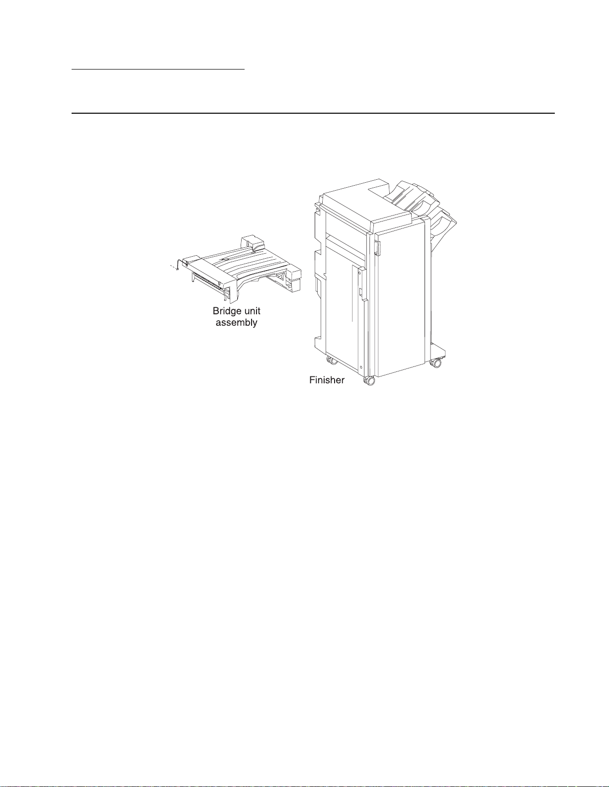
Finisher
The optional finisher staples, punches, folding and stapling, and stacks media transferred from the Lexmark™
C930, C935, X940e and X945e. Output is stacked in the upper media bin or separately collated in the stacker
media bin or folded and stapled in the booklet bin.
5057-XXX
Standard Finisher weight
Unpacked: 59 kg (130 lbs)
Booklet Finisher weight
Unpacked: 87.5 kg (193 lbs)
Components
The finisher is composed of the following components.
• Bridge unit assembly block to feed media from the printer to the finisher
• Punch block to punch media
• Compiler tray block to align media
• Stapler block to staple a set of media at specified positions
• Booklet unit and tray
General information 1-1
Page 22
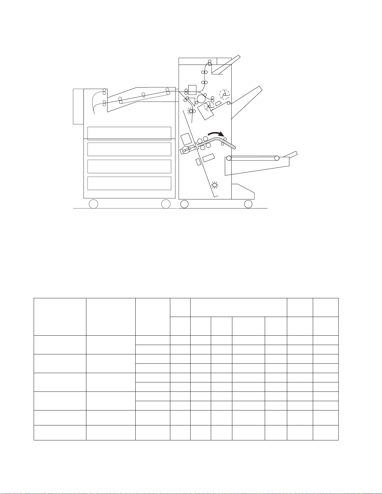
5057-XXX
Media path overview
Media size and weight
The following shows media sizes and weights that the finisher can handle, as well as applicable functions for
each media size.
The printer and the finisher handle different media sizes and weights. For this reason, if the printer has printed
media that the finisher cannot handle, the exit 1 diverter gate in the printer is switched to eject the media from
Exit 2 onto the bridge unit assembly. Refer to the Printer Service Manual for additional information on the printer.
Media size/orientation and applicable functions
Short edge
Media
description
Size
first (SEF)/
Long edge
first (LEF)
B5
182 x 257 mm
Executive 7.25 x 10.5 in.
184.2 x 27 0 mm
Letter 8.5 x 11 in.
215.9 x 279.4 mm
A4
210 x 297
SEF Yes No No No No No No
LEF Yes Yes Yes Yes
SEF Yes No No No No No No
LEF Yes Yes Yes Yes
SE F Ye s Yes Ye s Yes
LEF Yes Yes Yes Yes
SE F Ye s Yes Ye s Yes
LEF Yes Yes Yes Yes2
Folio (foolscap) 8,5 x 13 in. SEF Yes Yes Yes Yes
Top
tray
Stacker
Stack Stack
Offset
stack
Punch Staple Booklet Folding
a(2)
Yes No No
a(2,3,4)
No No No
a(2)
Yes Yes Yes
a(2,3,4)
Yes No No
a(2)
Yes Yes Yes
,a(3,4)
Yes No No
a(2)
Yes Yes Yes
Legal 8.5 x 14 in. SEF Yes Yes Yes Yes
1-2 Printer Finisher Service Manual
a(2)
Yes Yes Yes
Page 23
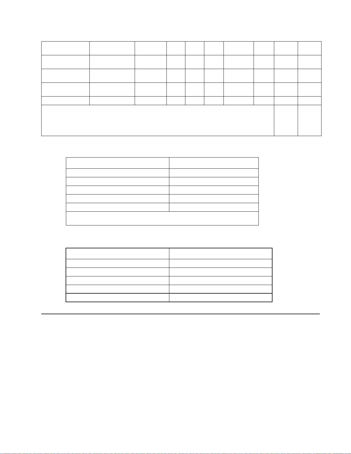
5057-XXX
B4
A3
Ledger 11 x 17 in. SEF Yes Yes Yes Yes
Custom size Same width with
Custom size Besides above Yes Yesb Yesb No No No No
a
Numbers (2,3,4) mean 2 holes, 3 holes, and 4 holes, respectively.
b
Applicable within the following range:
Media width: 203.2—297 mm
Media length: 182—431.8 mm
257 x 364 mm
297 x 420 mm
standard size
SE F Ye s Yes Ye s Yes
SE F Ye s Yes Ye s Yes
Yes Yes Yes Ye s Yes No No
a(2)
Yes Yes Yes
a(2,3,4)
Yes Yes Yes
a(2,3,4)
Yes Yes Yes
Media weight
Description Maximum weight
For punching 52–176 gsm
For stapling 52–226 gsm*
For ejecting in the stacker media bin 52–226 gsm
For ejecting in the upper media bin 52–226 gsm
For folding and stapling 52-226 gsm
* The amount of media capable of being stapled will be less than 50 if the media
weight is greater than 90 g/m
2
.
Features
Media processing requested Destination of media
No post-processing Upper media bin or stacker media bin
Punching Upper media bin or stacker media bin
Stapling Stacker media bin
Punching and stapling Stacker media bin
Folding and stapling Booklet tray
Finisher theory
Media transport
This section describes the transfer of media from the printer to a specified bin.
The following figures illustrate layouts (front view) of sensors, rollers, and main blocks, as well as a layout (rear
view) of the main components.
General information 1-3
Page 24
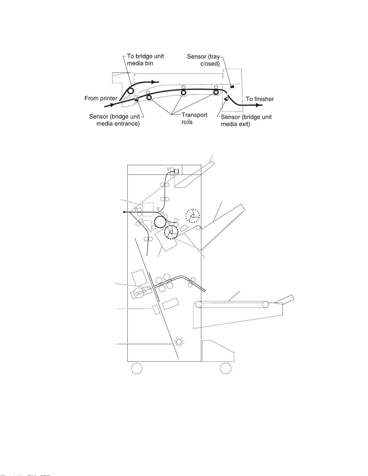
5057-XXX
Bridge unit assembly paper path
Finisher media path
Upper Media Bin
Punch Unit
From Bridge Unit
Knife Folding
Booklet Stapler Unit
End Guide
Stapler Unit
Stacker Media Bin
Compiler Media Unit Assembly
Booklet Bin
1-4 Printer Finisher Service Manual
Page 25
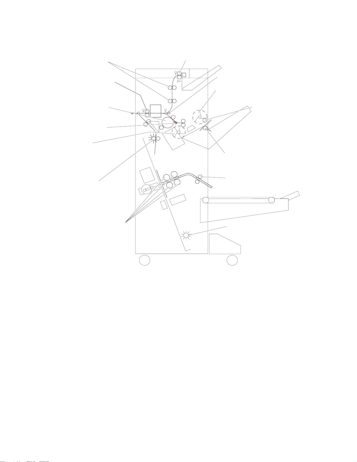
Finisher roll assemblies
Upper Media Transport Roll Assembly –
driven by drive motor (buffer/transport)
5057-XXX
Upper Media Exit Roll Assemblydriven by motor (exit)
Finisher Media Entrance
Roll Assembly – driven by
drive motor (entrance paddle)
Buffer Roll Assembly –
driven by drive motor
(buffer/transport)
Buffer Diverter Gate
Main paddle assembly
driven by drive motor
(entrance paddle)
Booklet entrance roll
assembly
media entrance drive motor
driven by booklet
Booklet fold roll assembly
driven by booklet folding/exit
drive motor assembly
Finisher Diverter Gate
Sub Paddle –
driven by drive motor (entrance/paddle)
Eject Clamp – driven by media
eject clamp motor
Media Eject Shaft Assembly –
driven by media eject motor assembly
Booklet media exit roll assembly
driven by booklet folding/exit
drive motor assembly
Booklet paddle
shaft assembly
General information 1-5
Page 26
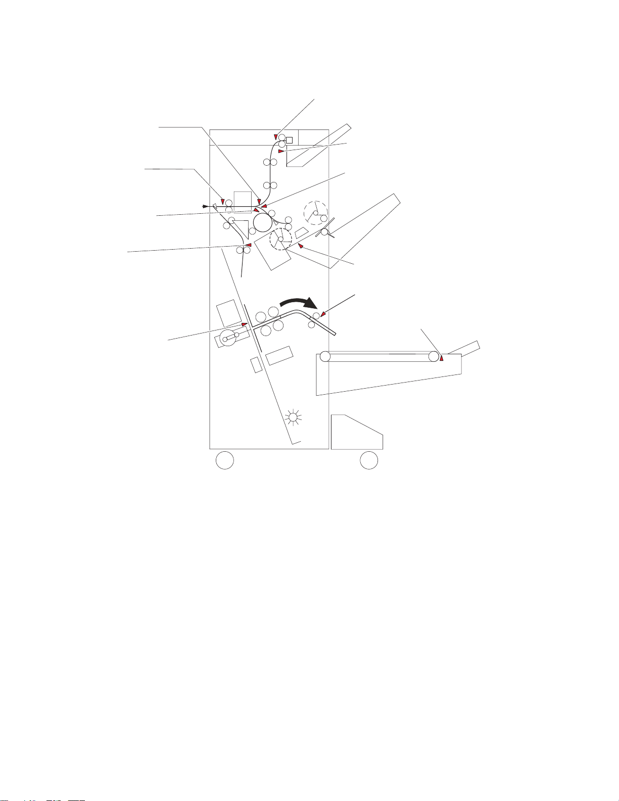
5057-XXX
Finisher media path sensors
Sensor
(diverter gate)
Sensor (upper media)
Sensor (upper media bin full)
Sensor
(media entrance)
Sensor
(buffer path)
Sensor
(booklet media entrance)
Sensor (booklet
compiler media in)
Sensor (lower media exit)
Sensor (lower media exit)
Sensor (booklet media exit)
Sensor (booklet bin media present)
1-6 Printer Finisher Service Manual
Page 27
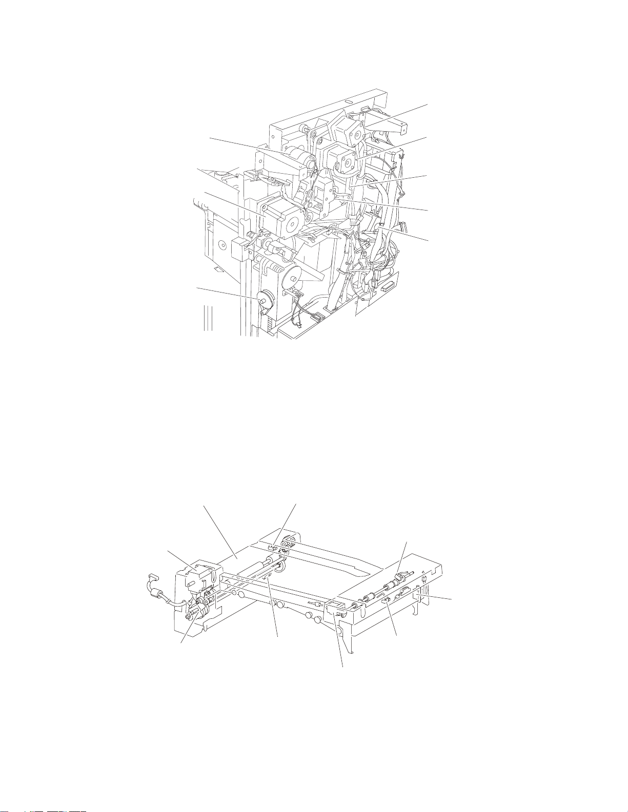
Finisher motors
5057-XXX
Drive motor (exit)
Media eject clamp motor
Media eject motor assembly
Stacker bin lift
motor assembly
Bridge unit assembly
When the printer designates the finisher, the media diverter gate in the printer activates, and media is fed from
the printer into the bridge unit assembly.
The bridge unit drive motor is activated by the trigger of the printer’s registration clutch, which drives the
transport belts in the bridge unit assembly. The motor power is transmitted to the two belts between the bridge
unit right shaft assembly and the bridge unit left shaft assembly.
Drive motor
(buffer/transport)
Finisher diverter gate solenoid
Buffer diverter solenoid
Drive motor
(entrance paddle)
The media fed to the bridge unit assembly is securely held between the transport belts and the pinch rolls, and
fed to the finisher.
Sensor (bridge unit
Bridge unit assembly
Bridge unit drive
motor assembly
Bridge unit
decurler clutch
Sensor (bridge unit
media exit)
top cover interlock
Sensor (bridge unit
bin media exit)
Bridge unit diverter
gate solenoid
Sensor (bridge unit
media entrance)
Bridge unit bin
media exit solenoid
General information 1-7
Page 28
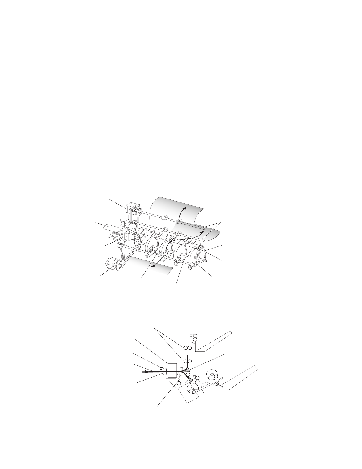
5057-XXX
From bridge unit assembly to punch
The media fed from the bridge unit assembly is fed into the finisher by the media entrance roll assembly located
on the entrance section of the finisher which is driven by the drive motor (entrance/paddle).
The media route inside the finisher is determined by the finisher diverter gate.
The finisher diverter gate is activated by the finisher diverter gate solenoid controlled by the printer.
The media is further fed in the finisher by the two upper media transport roll assemblies, or the buffer roll
assemblies that are driven by the motor (buffer/transport), and passes through the punch unit.
The sensor (finisher media entrance) becomes low upon detecting media. After a certain amount of time has
passed and the level has changed to high, the motor (buffer/transport) that drives the upper media transport roll
assembly or the buffer roll assembly starts reverse rotation.
The media is returned to the punch unit by the upper media transport roll assembly or the buffer roll assembly,
and is stopped with its end gently pressed against the three punch media stopper assemblies.
The three punch media stopper assemblies in the punch unit drop to let media pass through when media is fed
to the exit (while the motor (buffer/transport) is rotating forward), but rise when media is returned (while the
motor (buffer/transport) is rotating reversely) to stop the media.
Thus, punch hole positions in the media feed direction are determined.
Drive motor (buffer/transport)
Punch unit
Finisher diverter
gate solenoid
Drive motor
(entrance paddle)
Sensor (finisher
media entrance)
Upper media transport roll assembly—driven by
drive motor (buffer/transport)
Punch unit
Sensor (finisher
media entrance)
Media
From bridge unit assembly
Finisher media entrance
roll assembly—driven by
drive motor (entrance/paddle)
Upper media transport
roll assembly
Punch unit
Finisher diverter gate
Buffer roll assembly
Finisher media
entrance roll
assembly
Finisher diverter gate
1-8 Printer Finisher Service Manual
Buffer roll assembly—
driven by drive motor (buffer/transport)
Page 29
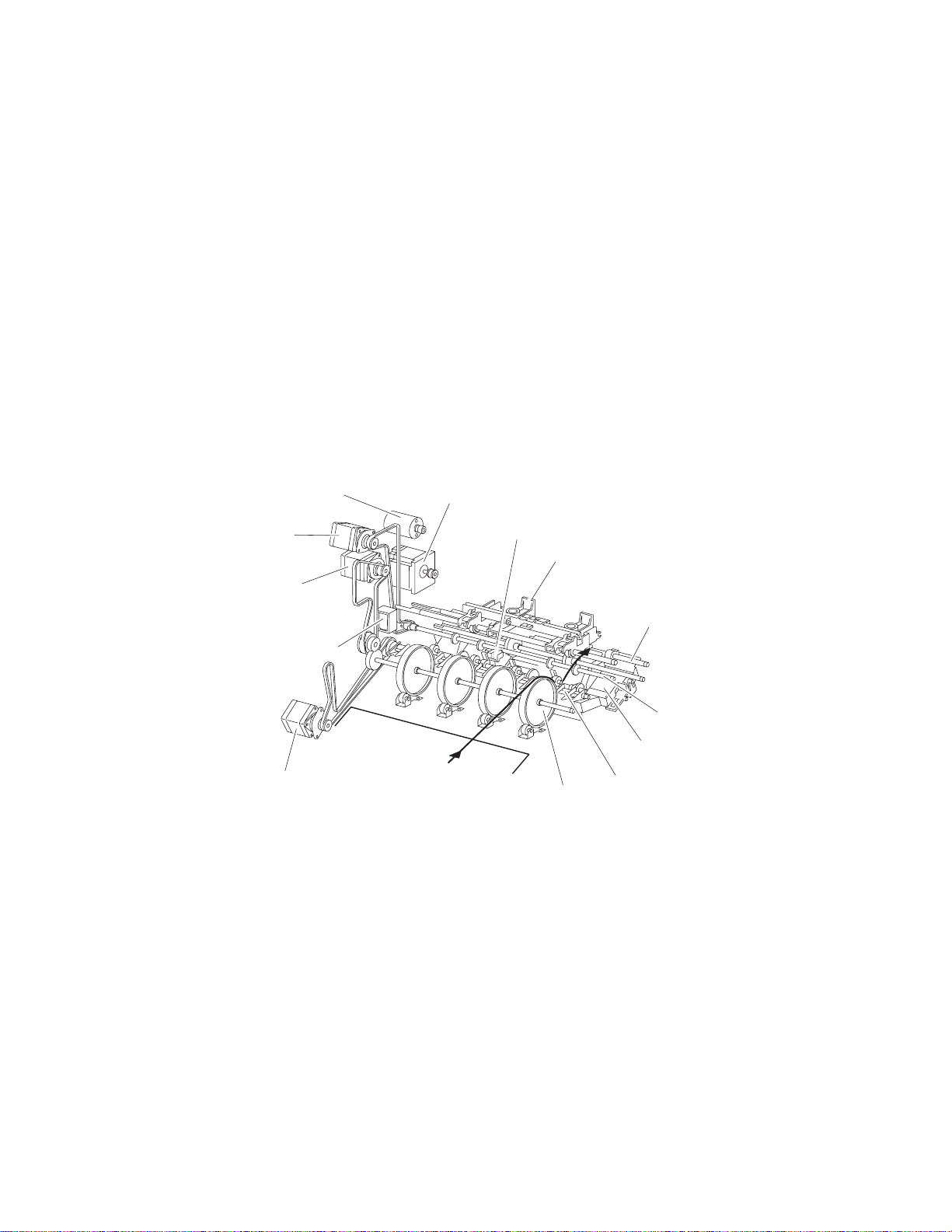
5057-XXX
From punch to compiler unit assembly
The media is transferred to the compiler unit assembly by the buffer roll assembly (driven by the motor (buffer/
transport)) and by the lower media exit roll assembly (driven by the drive motor (exit)).
When the first media reaches the compiler unit assembly, the media eject clamp motor is activated to lower the
media eject clamp so that the media eject clamp and the media eject shaft assembly can clamp the media.
Thus, the media transferred from the punch unit is held by the media eject shaft assembly and the media eject
clamp (driven by the media eject motor assembly) and is fed to the exit.
When the media trailing edge passes through the sensor (lower media exit), the media eject motor assembly
starts reverse rotation to return the media to the compiler unit assembly.
When the following media reaches the compiler unit assembly, the media eject clamp is raised, and the media
that has passed through the lower media exit roll assembly falls on the compiler unit assembly.
At this time, the three main paddles are rotated by the main paddle shaft assembly to feed the media so that the
media trailing edge butts against the rear wall of the compiler unit assembly.
The sub paddle solenoid of the media eject unit assembly is activated to lower the sub paddle so that the media
can be fed to the compiler unit assembly.
Media eject clamp motor
Drive motor (exit)
Drive motor
(buffer/transport)
Buffer diverter solenoid
Drive motor (entrance/paddle)
Media eject motor assembly
Sensor (lower media exit)
Eject clamp
Buffer roll assembly
Buffer diverter gate
Media eject
shaft assembly
Lower media exit
roll assembly
Compiler unit assembly
General information 1-9
Page 30
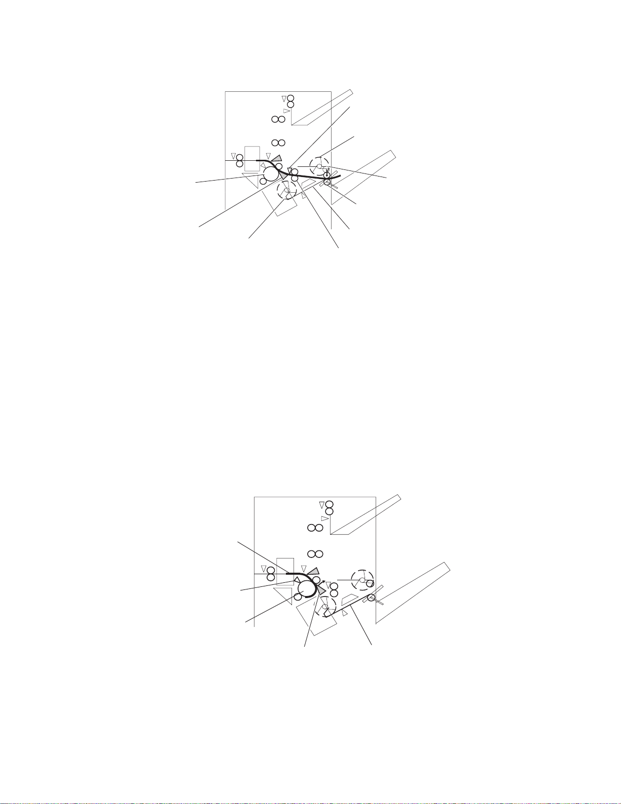
5057-XXX
Sensor (lower media exit)
Sub paddle—driven by
drive motor (entrance/paddle)
Buffer roll assembly—
driven by drive motor
(buffer/transport)
Media eject shaft assembly—
Eject clamp—driven
by eject clamp motor
driven by media eject motor asm
Buffer diverter
Main paddle
motor—driven by
motor (entrance/paddle)
When printing multiple sets, while stapling the first set on the compiler unit assembly or ejecting it to the stacker
media bin, the first media of the second set will not be fed to the compiler unit assembly.
When the first media of the second set reaches the finisher, the buffer diverter solenoid is activated by the
printer command and by the sensor (finisher media entrance) to switch the buffer diverter gate.
Thus, the media route is switched into the buffer roll assembly’s circumferential direction. (This operation is
called the buffer path.)
The first media of the second set is aligned with the second media, and then they are fed together to the
compiler unit assembly.
Even for one sheet of media, the buffer path operation is executed in the same way. The media is stacked
temporarily on the compiler unit assembly, and then ejected in the stacker media bin.
After the buffer path is executed for the first media, if a second media of a different size comes, the first media is
fed to the compiler unit assembly, but the second one is fed to the compiler unit assembly without the buffer
path. At this time, a certain delay time is provided to prevent the second media from colliding with the first one.
Compiler unit assembly
Lower media exit
roll assembly—driven by
motor (exit)
Media
Sensor
(buffer path)
Buffer roll assembly
driven by drive motor
(buffer/transport)
1-10 Printer Finisher Service Manual
Buffer
diverter gate
Compiler unit
assembly
Page 31

5057-XXX
From compiler unit assembly to stacker media bin
Stapled media on the compiler unit assembly (stapling mode) or aligned media (non-stapling mode) are held
between the media eject clamp and the media eject shaft assembly.
The media eject shaft assembly is driven by the media eject motor assembly to transfer media to the stacker
media bin.
After media is transferred to the stacker media bin, it is held by the clamp paddle attached to the media eject
shaft assembly.
From punch to upper media bin
The media to be ejected to the upper media bin is switched in the media path by the finisher diverter gate located
behind the punch and fed in the upper media transport roll assembly direction.
The finisher diverter gate is switched by the finisher diverter gate solenoid. While the solenoid is activated, media
is fed in the upper media transport roll assembly direction.
The two upper media transport roll assemblies driven by the motor (buffer/transport) feed media to the upper
media exit roll assembly top at the top of the finisher.
The upper media exit roll assembly top driven by the drive motor (exit) ejects the media to the upper media bin.
The upper media exit roll assembly decelerates after a specified period of time from the following trigger events.
Functions of sensors along the media path
Bridge unit assembly
• Sensor (bridge unit media entrance)
— A photo-interrupter sensor that detects whether media is fed from the printer to the bridge unit assembly
— It turns high (+5 V dc) (light receiving) when media enters the bridge unit assembly.
• Sensor (bridge unit media exit)
— A photo-interrupter sensor that detects whether media passes through the bridge unit assembly
— It turns high (+5 V dc) (light receiving) when media reaches this sensor, and turns low (0 V dc) when
media exits from the bridge unit assembly.
• Sensor (bridge unit top cover interlock)
— A photo-interrupter sensor that detects open/close of the bridge top cover assembly of the bridge unit
assembly
— It turns high (+5 V dc) (light receiving) when the bridge top cover assembly opens.
Sensor (bridge unit
Bridge unit assembly
Bridge unit drive
motor assembly
top cover interlock
Sensor (bridge unit
bin media exit)
Bridge unit
decurler clutch
Sensor (bridge unit
media exit)
Bridge unit diverter
gate solenoid
Sensor (bridge unit
media entrance)
Bridge unit bin
media exit solenoid
General information 1-11
Page 32

5057-XXX
Finisher
• Sensor (finisher media entrance)
— A photo-reflective sensor detects whether media is fed from the bridge unit assembly to the finisher
— It turns high (+5 V dc) while media is present within the sensing area.
— When the level turns high due to the first media of the second set during multi-set printing, this sensor
activates the buffer diverter solenoid to switch the buffer diverter gate so that the media goes in the
buffer roll assembly’s circumferential direction.
• Sensor (diverter gate)
— A photo-reflective sensor that detects the leading edge of the media
— It turns low (0 V) when the front end reaches the sensing area.
• Sensor (lower media exit)
— A photo-interrupter sensor that detects whether media passes through the sensor (lower media exit)
— It turns high (+5 V) (light receiving) when the actuator is driven out of the sensing area by the media.
— When the level turns high, this sensor activates the front tamper motor and the rear tamper motor on the
compiler unit assembly.
— This sensor is also used to control on/off of the media eject motor assembly
• Sensor (compiler media present)
— A photo-interrupter sensor that detects whether media is present or not on the compiler unit assembly.
— While media is present, the actuator is outside the sensing area, and the sensor turns high (+5 V dc)
(light receiving).
• Sensor (buffer path)
— A photo-interrupter sensor that detects whether media is fed toward the buffer roll assembly
— While media is present, the actuator is outside the sensing area, and the sensor turns at high (+5 V dc)
(light receiving).
• Sensor (upper media exit)
— A photo-interrupter sensor that detects whether media is fed to the upper media exit roll assembly top at
the exit side of the upper media bin
— When the media is fed, the actuator leaves from the sensing area, and the sensor turns high (+5 V dc).
• Sensor (upper media bin full)
A photo-reflective sensor that detects the stack volume of media in the upper media bin
Sensor (diverter gate)
Sensor (finisher
media entrance)
From bridge unit
Sensor (buffer path)
Sensor (upper media exit)
Sensor (upper media bin full)
Sensor (lower media exit)
Sensor (compiler media in)
1-12 Printer Finisher Service Manual
Page 33

Punch unit
This section describes the media punching operation of the punch.
Two types of punch are provided: the 2/3-hole type and the 2/4-hole type.
The following explains the 2/3-hole type (2-hole/3-hole auto-switching).
Every type has the same construction, except for the sensor (punch hole select) that is provided for the 2-hole
type and 3-hole type only.
Adjusting punching positions
The punching positions from the media edge in the direction of feed are determined by gently pressing the
media against the three punch media stopper assemblies.
The three punching positions from the media edge in the direction of media width are determined by the
following method.
5057-XXX
• Activate the punch carriage shift motor assembly, and move the punch to the front side until the sensor
(punch carriage shift HP) turns low.
• Reversely rotate the motor, and move the punch to the rear side until the sensor turns high to determine the
home position.
• The punch carriage shift motor assembly is activated to move the punch to the front until the sensor (punch
unit side registration 1) and the sensor (punch unit side registration 2) detects the media edge, and then the
punch is further moved to the front according to the pulse-number determined by the media size. (The
punch carriage shift motor assembly stops at this position.)
Sensor (punch carriage shift HP)
Sensor (punch cam front)
Sensor (punch
hole select)
Sensor (punch unit HP)
Sensor (punch unit motor encoder)
Punch carriage shift motor assembly
Sensor (punch unit side
registration 2)
Sensor (punch unit side
registration 1)
Punch unit motor
General information 1-13
Page 34

5057-XXX
Punching
After punching positions are determined, the punch unit motor is activated to move the cam plate. With the
movement of the cam plate, the pins descend along the guide holes to punch the media.
This operation is performed for each sheet of media.
The cam plate can lower the pins even while it is moving to the front or rear side.
The punch unit motor is rotated forward or reversely for each sheet of media, which is triggered by the sensor
(punch cam front) being turned on/off.
Pin position
Sensor (punch hole select)
Home
position
Sensor (punch cam front)
Sensor (punch unit HP)
Punch unit motor
Pin
Cam plate
3 hole
position
Home
position
2 hole
position
Home
position
1-14 Printer Finisher Service Manual
Page 35

5057-XXX
Detecting punch waste full
Punch waste is stored in the punch waste box.
A sensor is provided to detect punch waste full.
When punch waste full is detected, it is notified to the operator only once.
Even if punch waste is not removed, the finisher can still punch media. However, it can spread punch waste
inside the machine.
Detecting punch waste box
The sensor (punch waste box set) detects whether the punch waste box is properly set.
When the sensor (punch waste box set) does not detect that the punch waste box is properly set for four
seconds, the punch waste box count is reset.
Functions of punch sensors/motors
• Sensor (punch unit side registration 1)
— A photo-reflective sensor that detects the side edge of large media
— Media side edge is detected by On/Off of this sensor while shifting the punch (containing this sensor) in
the direction of media width.
— The sensor remains at high (+5 V dc) while media is present, and turns low when media side edge is
detected.
• Sensor (punch unit side registration 2)
— A photo-reflective sensor that detects the side edge of small media
— This sensor has the same function as the sensor (punch unit side registration 1).
• Sensor (punch carriage shift HP)
— A photo-interrupter sensor that detects the home position of the moving punch
— It turns high (+5 V dc) (light blocking) when the home position is detected.
• Sensor (punch unit HP)
— A photo-interrupter sensor that detects the home position of the cam plate that lowers the punching pins
— It turns high (+5 V dc) when the home position is detected.
• Sensor (punch hole select)
— A photo-interrupter sensor that detects the rear position of the cam plate
— It turns high (+5 V dc) when the rear position is detected.
— This sensor also detects the cam position to switch punch holes (2-hole/3-hole).
• Sensor (punch cam front)
— A photo-interrupter sensor that detects the front position of the cam plate
— It turns high (+5 V dc) when the front position is detected.
— This sensor is used to determine to which side (front or rear) the cam plate should be moved.
• Sensor (punch unit motor encoder)
— A photo-interrupter sensor that detects pulse generated by the encoder attached to the punch unit motor
— It counts punch unit motor revolutions and becomes a trigger to stop the motor (by shutting off the
current).
• Punch carriage shift motor assembly
— A stepping motor to move the punch in the media width direction
• Punch unit motor
— A DC motor to move the cam plate that lowers the punching pins
— Forward rotation of the motor moves the cam plate to the front side, and reverse rotation moves it to the
rear side.
General information 1-15
Page 36

5057-XXX
• Sensor (punch waste box set)
— A photo-interrupter sensor that detects whether the waste box is properly set
— When the punch waste box is properly set, the actuator of the box blocks the light transmission of the
sensor, which turns the sensor to high (+5 V dc).
• Sensor (punch waste box full)
A photo-interrupter sensor that detects whether the punch waste box is filled with punch waste.
Sensor (punch carriage shift HP)
Sensor (punch cam front)
Sensor (punch
hole select)
Sensor (punch unit HP)
Sensor (punch unit
motor encoder)
Compiler unit assembly
This section describes the operation of the compiler unit assembly which aligns the media edge transferred from
the punch unit.
Outline of operation
When media is fed onto the compiler unit assembly, tamping is performed to align the media edge in the media
width direction.
Punch carriage shift motor
Sensor (punch unit side registration 2)
Sensor (punch unit side
registration 1)
Punch unit motor
When ejecting stapled sets of media to the stacker media bin, if they are stacked in the stacker media bin with
the same staple position, the height of the stapled portion will increase. This will cause improper compiling of
media due to butting of the following media. To prevent such improper compiling, offsetting is required by
shifting the staple position between sets of media.
Rear tamper
Sensor (rear
tamper HP)
Rear tamper motor
1-16 Printer Finisher Service Manual
Sensor (compiler
media in)
Front tamper
Sensor (front tamper HP)
Front tamper motor
Page 37

5057-XXX
Capacity of compiler unit assembly
Media volume that can be stacked on the compiler unit assembly is limited as shown in the table below.
The number of sheets depends on whether media is stapled or not, as well as on media size.
If the number of sheets of one set to be stapled exceeds the limit, the exceeding sheets are not stacked on the
compiler unit assembly, and are forcibly ejected to the stacker media bin without being stapled.
This forcible ejection is performed to prevent damage to the staple assembly.
When feeding large media in the non-staple mode, there may be a misalignment depending on media
characteristics. For this reason, the default media capacity is set to a smaller value.
Compiler unit assembly media capacity
Condition Min. Default Max.
Staple mode 2 50 75
For small media (less than 216 mm in the feed direction) in
non-staple mode
For large media (216 mm or more in the feed direction) in
non-staple mode
10 50 100
10 25 100
Compiler unit assembly operation with multiple media sizes
When two or more media sizes are used and their widths are the same (example: A4L and A3S), all the sheets
are compiled and stapled as a set on the compiler unit assembly, and then ejected to the stacker media bin.
When two or more media sizes with different media width are used, stapling media on the compiler unit
assembly is stopped when a different size is detected. Such different-size sheets of media are forcibly ejected to
the stacker media bin.
Tamping
When media is fed from the punch to the compiler unit assembly, tamping is performed to align the media in the
media width direction on the compiler unit assembly.
Tamping is an operation to align media to the specified position on the compiler unit assembly. The front tamper
or rear tamper is moved to the end of the media by its motor.
Tamping is executed each time when a sheet of media reaches the compiler unit assembly. Additional tamping
is executed after the last sheet is tamped.
There are three types of tamping.
• Front tamping–Tamping by the rear tamper with the front tamper fixed at the home position
• Rear tamping–Tamping by the front tamper with the rear tamper fixed at the home position
• Center tamping–Tamping by the front and rear tampers to align media to the center
General information 1-17
Page 38

5057-XXX
Front tamping
Front tamping is used in the following cases.
• In the non-staple mode
• When executing front stapling (corner)
The tamper positions during front tamping are shown below.
Sensor (front tamper HP)
Front
Sensor (rear tamper HP)
Rear
Front tamper motor
Position Description
1 Front tamper home position–sensor (front tamper HP)
2 Front tamper size position
3 Front tamper offset position
4 Rear tamper home position–sensor (rear tamper HP)
5 Rear tamper standby position
6 Rear tamper tamping position
7 Rear tamper offset position
Front tamper
Rear tamper
Rear tamper motor
1-18 Printer Finisher Service Manual
Page 39

Rear tamping
Rear tamping is used in the following cases.
• When executing rear stapling (corner)
• When executing dual stapling
The tamper positions during rear tamping are shown below.
Sensor (front tamper HP)
Front
5057-XXX
Sensor (rear tamper HP)
Rear
Front tamper motor Front tamper
Position Description
1 Front tamper home position–sensor (front tamper HP)
2 Front tamper tamping position
3 Front tamper offset position
4 Rear tamper home position–sensor (rear tamper HP)
5 Rear tamper size position
6 Rear tamper offset position
Rear tamper
Rear tamper motor
General information 1-19
Page 40

5057-XXX
Center tamping
Center tamping is used when executing rear stapling (straight).
The tamper positions during center tamping are shown below.
Sensor (front tamper HP)
Front
Sensor (rear tamper HP)
Rear
Front tamper motor Front tamper
Position Description
1 Front tamper home position–sensor (front tamper HP)
2 Front tamper standby position
3 Front tamper tamping position
4 Front tamper offset position
5 Rear tamper home position–sensor (rear tamper HP)
6 Rear tamper standby position
7 Rear tamper size position
8 Rear tamper offset position
Rear tamper
Rear tamper motor
Determining tamper home position
When the sensor (lower media exit) turns high (+5 V dc) (light receiving), the front and rear tamper motors on
the compiler unit assembly are activated, and the front and rear tampers start moving.
The front tamper home position is determined when the front tamper enters the sensor (front tamper HP)
sensing area.
In the same way, the rear tamper home position is determined when the rear tamper enters the sensor (rear
tamper HP) sensing area.
Tamping
Tamping is executed after a preset time has passed after the sensor (compiler media present) turns high
(+5 V dc) when media is detected on the compiler unit assembly.
1-20 Printer Finisher Service Manual
Page 41

5057-XXX
Offsetting
Offsetting is an operation to shift the position of media to be ejected to the stacker media bin so that boundaries
between media units (sets of media, job units, etc.) can be easily recognized.
Offsetting is executed for staple positions:
• During front stapling (corner)–Shifts stapled sheets using the front tamper by 20 mm to the rear side before
ejecting them to the stacker media bin
• During rear stapling (corner/straight)
— For media with a width of 216 mm or more [rear staple (corner)]–Shifts stapled sheets using the rear
tamper by 20 mm to the front side before ejecting them to the stacker media bin
— For media with a width of less than 216 mm [rear staple (straight)]–Shifts stapled sheets using the front
tamper by 9 mm to the rear side before ejecting them to the stacker media bin.
During dual stapling:
• Shifts stapled sheets using the front tamper by 9 mm to the rear side before ejecting them to the stacker
media bin.
• Offsetting is not executed (0 mm) for small media.
Functions of compiler unit assembly sensors/motors
• Sensor (compiler media in)
— A photo-interrupter sensor that detects whether media is present or not on the compiler unit assembly
— When media is detected, the actuator leaves the sensing area, which turns the sensor to high (+5 V dc)
(light receiving).
• Sensor (front tamper HP)
— A photo-interrupter sensor that detects the front tamper home position
— When the front tamper comes to the home position, it enters the sensor’s sensing area, which turns the
sensor to high (+5 V dc) (light blocking).
• Sensor (rear tamper HP)
— A photo-interrupter sensor that detects the rear tamper home position
— When the rear tamper comes to the home position, it enters the sensor’s sensing area, which turns the
sensor to high (+5 V dc) (light blocking).
• Front tamper motor
— A stepping motor that moves the front tamper for tamping
— Clockwise rotation of this motor moves the front tamper to the rear side. Counterclockwise rotation of this
motor moves the tamper to the front side.
General information 1-21
Page 42

5057-XXX
Stapler
• Rear tamper motor
— A stepping motor that moves the rear tamper for tamping
— Clockwise rotation of this motor moves the rear tamper to the front side. Counterclockwise rotation of this
motor moves the tamper to the rear side.
Rear tamper
Front tamper
Sensor (rear
tamper HP)
Rear tamper motor
Sensor (compiler
media in)
Front tamper motor
Sensor (front tamper HP)
This section describes the operation of the stapler.
Stapling operation
Sheets of media fed from the punch are tamped on the compiler unit assembly, and then stapled at specified
positions by the command of the printer.
Staple positions
There are four stapling modes:
• Front staple (corner) [front corner]
The stapler staples a set of media obliquely (45 degrees) after the rear tamper
aligns the media to the front side.
• Rear staple (corner) [rear corner]
This type of stapling is applied for media with a width of 216 mm or more.
The stapler moves to the rear corner and staples a set of media obliquely (45
degrees) after the front tamper aligns the media to the rear side.
Rear
Process direction
Front
Rear
1-22 Printer Finisher Service Manual
Process direction
Front
Page 43

• Rear Staple (Straight) [rear straight]
This type of stapling is applied for media with a width of less than 216 mm.
The Stapler staples a set of media in parallel with the media edge after the front
tamper aligns the media to the rear side.
• Dual Staple [dual]
The Stapler staples a set of media at fixed positions (front/rear sides) in parallel
with the media edge after the front tamper aligns the media to the specified position
for each media size.
Media sizes that allow stapling
5057-XXX
Rear
Process direction
Front
Rear
Process direction
Front
Media size that allows stapling depends on stapling positions.
The following table shows media sizes and the applicability of stapling for each staple position.
Front
corner
A3 SEF Yes Yes No Yes
A4 LEF Yes Yes No Yes
11 x 17 in. SEF Yes Yes No Yes
8.5 x 11 in. LEF Yes Yes No Yes
8K SEF(GCO), 16K LEF(GCO) Yes Yes No Yes
B4 SEF, B5 LEF Yes Yes No Yes
8 x 10 in. LEF Yes Yes No Yes
8.5 x 14 in. SEF / 8.5 x 13 in. SEF /
8.5 x 11 in. SEF
A4 SEF Yes No Yes Yes
8 x 10 in. SEF Yes No Yes Yes
Yes: Applicable, No: Not applicable
Yes N o Ye s Ye s
Rear
corner
Rear
straight
Dual
Stapling one sheet
Upon receiving the stapling command from the printer with one sheet remaining on the compiler unit assembly,
the finisher ejects the media to the stacker media bin without stapling it.
General information 1-23
Page 44

5057-XXX
Stapling multiple size media
When sheets with different sizes and the same width (example: A4L and A3S) are present on the compiler unit
assembly, all the sheets are stapled and then ejected to the stacker media bin.
When sheets with different widths are present on the compiler unit assembly, stapling is stopped when a
different width is detected. Such different-width sheets are forcibly ejected to the stacker media bin.
Media limits for stapling
The number of sheets to be stapled is limited to prevent damage to the stapler.
• If the number of sheets of one set to be stapled exceeds the limit of the compiler unit assembly, the
exceeding sheets are not stacked on the compiler unit assembly, and are forcibly ejected to the stacker
media bin without being stapled.
• After the forcible ejection of media, if the number of following sheets of one set to be stapled exceeds the
limit of the compiler unit assembly, the exceeding sheets are also ejected forcibly to the stacker media bin
without being stapled.
• After that, even if the number of following sheets of one set to be stapled falls within the limit, the sheets are
also ejected forcibly to the stacker media bin without being stapled.
The upper limit (and default) of the compiler unit assembly media capacity when stapling is 50 (variable (10 to
100) by the non-volatile memory).
Stapler operation
The stapler stays at the front home position, that is, at the front staple (corner) position when the power is
turned on.
The stapler starts stapling when a set of sheets to be stapled is stacked on the compiler unit assembly.
The stapler does not move during stapling in the front staple mode.
In any mode other than the front staple mode, the stapler moves to the specified position, and then performs
stapling.
Stapler carriage motor asm
Media handling
direction
Sensor (stapler carriage HP)
1-24 Printer Finisher Service Manual
Page 45

5057-XXX
Stapler unit assembly
The stapling operation is executed by closing the stapler unit assembly.
The stapler unit assembly, containing the staple motor, the sensor (staple home), the sensor (self priming), and
the sensor (low staple), is activated by the staple motor.
Forward (clockwise) rotation of the motor drives the stapler to staple a set of sheets, and returns the stapling unit
to the home position.
If stapling fails, the motor rotates reversely (counterclockwise) to return the stapler unit assembly to the home
position.
When staples become low, the low staple sensor detects it, and stapling stops automatically, displaying an
alarm message. The message is also displayed when the staple cartridge is not installed.
Sensor (staple home)
Sensor (self priming)
Sensor (low staple)
Stapler unit assembly
Stapler unit motor
Functions of stapler sensors/motors
• Sensor (stapler carriage HP)
— A photo-interrupter sensor that detects the stapler home position, rear staple (corner) position, and rear
staple (straight) position
— It turns high (+5 V dc) (light blocking) when the stapler comes to the specified position.
• Stapler carriage motor assembly
— A stepping motor that moves the stapler unit assembly
— Clockwise rotation of this motor moves the stapler unit assembly to the rear side, while counterclockwise
rotation moves the stapler unit assembly to the front side.
• Sensor (low staple) in the stapler unit assembly
— A photo-interrupter sensor that detects when the stapler unit assembly is nearly out of staples
— It turns high (+5 V dc) when 20 staples are left.
• Sensor (self priming) in the stapler unit assembly
— A photo-interrupter sensor that detects that staples are at the stapler unit assembly end; it also detects
failure in stapling
— It turns low (0 V dc) (light blocking) when stapling is ready.
• Sensor (staple home) in the stapler unit assembly
— A photo-interrupter sensor that detects the stapler unit assembly home position; it also detects failure in
stapling
— This sensor also functions as a trigger to stop the staple motor.
— It turns low (0 V dc) (light blocking) while the stapler unit assembly stays at the home position.
General information 1-25
Page 46

5057-XXX
• Stapler unit motor (in the stapler unit assembly)
— A DC motor to activate the stapler unit assembly for stapling
— Clockwise rotation of this motor enables stapling, while counterclockwise rotation returns the stapler unit
assembly.
Sensor (stapler carriage HP)
Booklet Operation
The booklet media entrance roll assembly driven by the booklet media entrance drive motor will deliver media
from the finisher entrance and stack it against the booklet end guide in the booklet unit. When the booklet end
guide is at the bottom of the booklet unit it will continue to accept media. Once the proper amount of media is
reached, stapling will occur and booklets will be delivered in sets to the booklet media bin.
Stapler carriage motor asm
Stapler
rack gear
The booklet media exit roll assembly is driven by booklet folding/exit drive motor assembly and delivers booklets
to the booklet media bin. During printing, paper drawn to the booklet compiler is aligned by the booklet paddle
shaft assembly which is driven by booklet paddle shaft drive Motor.
When a sheet of paper enters the booklet compiler, tamping operation is performed by two moving tampers
moving towards the front and rear. The front tamper is driven by front booklet tamper drive motor; rear booklet
tamper drive motor. Tamping operation will be performed a final time after the last sheet is received.
Documents in the compiler tray are assembled towards the front. For center stapling and folding positions, one
set of document is assembled and moved to the center.
The booklet end guide is lifted to where the fold will divide the paper into two equal halves. When the printouts
are stapled, the booklet end guide will be raised so that the stapled position is at the folding position. The
stapling position is slightly lower than the folding position center line.
When the movement from the booklet folding/exit drive motor is transferred to the knife through the engagement
of the sector gear, the knife will thrust forward and then return to the original position after one full rotation. At the
folding position, the knife is thrust forward to fold the paper between booklet folding roll and booklet folding nip
roll.
Paper is folded into two halves by the booklet folding roll driven by the booklet folding/exit drive motor and is
delivered to the booklet media bin by the booklet media exit roll assembly. The booklet media bin belt will move
at a fixed interval for every set of booklets that are created.
1-26 Printer Finisher Service Manual
Page 47

Functions of booklet sensors and motors
5057-XXX
• Sensor (booklet media entrance)
— This photo sensor detects the media delivery to the booklet unit.
• Sensor (booklet media exit)
— This photo sensor detects paper delivery to booklet media bin.
• Booklet media entrance drive motor assembly
— This stepping motor drives the booklet media entrance roll assembly.
• Booklet folding/exit drive motor assembly
— This DC motor drives booklet folding roll, booklet media exit roll assembly, and knife.
General information 1-27
Page 48

5057-XXX
• Booklet knife solenoid
— This solenoid transfers the booklet folding/exit drive motor assembly to the knife through the gear.
Booklet media
entrance roll
assembly
Booklet folding
roll assembly
Booklet media
exit roll assembly
Sensor (booklet media
exit roll assembly)
• Sensor (booklet front tamper HP)
Booklet folding/exit
motor assembly
Sensor (booklet
media entrance)
Booklet media entrance
drive motor
Booklet knife solenoid
— This photo sensor detects the home position of the booklet front tamper.
• Sensor (booklet rear tamper HP)
— This photo sensor detects the home position of the booklet Rear tamper.
• Sensor (booklet compile media in)
This photo sensor detects paper present in the booklet compiler tray.
— Booklet front tamper motor
This stepping motor drives the booklet front tamper.
• Booklet rear tamper motor
— This stepping motor drives the booklet rear tamper.
• Sensor (booklet knife HP)
— This photo sensor detects the home position (stored condition) of knife.
• Sensor (knife folding)
— This photo sensor detects the fold position (protruded condition) of knife.
• Booklet staple assembly
— This booklet stapler consist of two stapler units (including stapler low switch) and booklet stapler head
motor.
• Booklet paddle motor
— This DC motor drives the paddle at the booklet section.
• Sensor (booklet end guide HP)
— This photo sensor detects the home position of the booklet end guide.
• Booklet end guide drive motor
— This stepping motor moves the booklet end guide up and down.
1-28 Printer Finisher Service Manual
Page 49

• Sensor (booklet drawer interlock)
— This photo sensor detects when the booklet unit is set.
• Sensor (booklet bin media present)
— This photo sensor detects paper availability on the booklet media bin. If 15 sets of printouts are detected
in the booklet media bin, it will be considered as Full Stack.
Upper media bin
5057-XXX
Booklet bin drive motor
Sensor (booklet bin
media present)
Operation
The upper media bin contains the sensor (upper media bin full) to detect the media stack volume in the upper
media bin.
Once the sensor detects a full stack (500 sheets) in the upper media bin, ejection of media to the upper media
bin is inhibited until a full stack is reset.
Functions of upper media bin sensors
• Sensor (upper media exit)
— A photo-interrupter sensor that detects that media has come to the upper media exit roll assembly top at
the exit of the upper media bin
— When media reaches the upper media exit roll assembly top, the actuator leaves the sensing area, which
turns the sensor to high (+5 V dc).
• Sensor (upper media bin full)
— A photo-reflective sensor that detects the media stack volume in the upper media bin
— It turns high (+5 V dc) when it detects a full stack.
General information 1-29
Page 50

5057-XXX
do
d
Stacker media bin
The stacker media bin goes up and down to an appropriate position according to the volume of media fed from
the compiler unit assembly so as to properly stack media to a full stack.
Operation
The stacker media bin moves to an appropriate position according to the volume of media fed from the compiler
unit assembly. The sensor (stacker bin level 1) and the sensor (stacker bin level 2) detect the height of media in
the stacker media bin, and the sensor (stacker bin level encoder) determines the volume of media in the tray.
When media or the stacker media bin comes between the light emitter and the photo-receiver of the sensor
(stacker bin level 1) and sensor (stacker bin level 2), the emitted light is blocked, and the sensors turn high. The
height of media or the stacker media bin is detected based on the levels of these sensors.
This sensor information is used to control the elevator motor. The motor is activated to move the stacker media
bin while the sensor (stacker bin level) turns from the light blocking state to the light receiving state.
Sensor (stacker bin level)
Bin: height
moves
Bin: proper
Bin: low
moves upward
wnwar
The sensor (stacker bin no media) is turned On or Off by the actuator attached to the carriage assembly right on
the rear side of the finisher. In case the stacker media bin abnormally goes up above the sensor (stacker bin no
media), the sensor (stacker bin upper limit) is installed above the sensor (stacker bin no media) for protection
against abnormal operation.
If an operator removes media from the stacker media bin during printing, it is detected by the sensor (stacker bin
level 2), and the ejection of media to the stacker media bin is inhibited. Then the elevator motor is activated to
move the stacker media bin to the sensor (stacker bin level 1) sensing area. Thus, the ejection of media to the
stacker media bin is restored.
If an operator removes media from the stacker media bin while printing is stopped, it is detected by the sensor
(stacker bin level 2). After three seconds have passed, the elevator motor is activated to move the stacker media
bin to the sensor (stacker bin level 1) sensing area. Thus, the ejection of media to the stacker media bin is
restored.
1-30 Printer Finisher Service Manual
Page 51

5057-XXX
The stacker media bin lowers according to the volume of media it contains. If any obstacle under the tray
hinders the tray from lowering, the stacker lower safety warning is detected, and the stacker media bin is
stopped.
Eject clamp motor
Sensor (stacker bin level 1)
Sensor (media
eject clamp HP)
Media eject
motor assembly
Sensor (media
eject shaft HP)
Stacker media bin
Sensor (stacker bin level 2)
Sensor (stacker bin
upper limit)
Sensor (stacker bin no media)
Stacker bin
lift motor assembly
Actuator
Sensor (stacker bin
level encoder)
General information 1-31
Page 52

5057-XXX
Full stack detection
A full stack is detected when media in the stacker media bin becomes full to prevent media jam or falling of
media to the floor. The stacker media bin can stack up to approximately 3000 sheets.
The media volume in the stacker media bin is detected at every 10% (approximately 300 sheets) and notified to
the Controller.
Furthermore, the stacker media bin can stack up to 200 sets (default) of stapled media.
The stacker media bin can continue to stack media until media volume reaches either of the limits above.
In the mix stacking mode, all the sizes are allowed until a media volume of approximately 300 sheets in the
stacker media bin is detected.
The mix stacking mode indicates one of the following cases:
• A larger (any size of media) sheet of media is stacked on a smaller sheet.
For example: A4LEF (297x210) media is stacked on A4SEF (210x297) media.
Note: When B5LEF (257x182) media is stacked on A4LEF (297x210) media, this is not mix stacking.
• A sheet of media of less than 11 inches is stacked in the stacker
media bin with the Staple Mode changed.
• An operator put a sheet (or sheets) when no media is remaining in the stacker media bin.
(The size and condition of media stacked in the tray are not identified.)
• Media was present in the stacker media bin when power was turned on.
(The size and condition of media stacked in the tray are not identified.)
• The finisher entered the Sleep Mode with mix stacking and then has exited the Sleep Mode.
• The post-processing mode has changed.
Top view of finisher tray
Functions of stacker media bin sensors/motors
• Sensor (stacker bin level 1)
— A light emitter and photo-receiver paired together to detect the height of media in the stacker media bin
— This sensor is used to control the elevator motor.
— When blocked by media or the tray, this sensor turns high, deciding that the stacker media bin is above
the reference level.
— To the contrary, when receiving light, this sensor turns low, deciding that the stacker media bin is below
the reference level.
— The high to low turning point of the sensor is defined as the reference level.
• Sensor (stacker bin level 2)
— A light emitter and photo-receiver paired together to detect the height of media in the stacker media bin
(same function as sensor (stacker bin level 1))
— This sensor is also used to control the elevator motor.
— When blocked by media or the tray, this sensor turns high, deciding that the stacker media bin is above
the reference level.
— To the contrary, when receiving light, this sensor turns low, deciding that the stacker media bin is below
the reference level.
• Sensor (stacker bin no media)
Rear
staple
Front
staple
1-32 Printer Finisher Service Manual
Page 53

— A photo-interrupter sensor that detects that the stacker media bin is at the highest position; it also
detects no media.
— When the actuator attached to the carriage assembly right enters the sensing area, the emitted light is
blocked, which turns the sensor to high (+5 V).
• Sensor (stacker bin upper limit)
— A photo-interrupter sensor that detects the stacker media bin’s abnormal elevation above the top position
(sensor (stacker bin no media) position)
— When the actuator attached to the carriage assembly right enters the sensing area, the emitted light is
blocked, which turns the sensor to high (+5 V).
• Sensor (stacker bin level encoder)
— A photo-interrupter sensor that counts the pulse of the Encoder attached to the Shaft-Elevator.
— The media volume in the stacker media bin is detected based on this count.
• Stacker bin lift motor
— A DC motor that elevates or lowers the stacker media bin
— Clockwise rotation elevates the tray, and counterclockwise rotation lowers the tray.
• Media eject motor assembly
— A stepper motor that ejects stapled or non-stapled media to the stacker media bin
— Clockwise rotation ejects media to the stacker media bin, and counterclockwise rotation reverses the
eject roll to feed the media from the punch to the compiler unit assembly.
• Media eject clamp motor
A DC motor that elevates or lowers the media eject clamp when feeding media from the punch to the
compiler unit assembly or from the compiler unit assembly to the stacker media bin
• Sensor (media eject clamp HP)
— A photo-interrupter sensor that detects the set clamp home position
— This sensor functions as a trigger to control On/Off of the set clamp clutch.
• Media eject clutch
When this clutch is activated, it transmits the media eject motor assembly rotating power to the media eject
shaft assembly.
Sensor (stacker bin level 1)
Eject clamp motor
5057-XXX
Sensor (stacker bin level 2)
Media eject clutch
Sensor (stacker bin upper limit)
Sensor (stacker bin no media)
Stacker bin
lift motor assembly
Sensor (media
eject clamp HP)
Media eject
motor assembly
Sensor (media
eject shaft HP)
Sensor (stacker bin
level encoder)
General information 1-33
Page 54

5057-XXX
Booklet tray
Paper is folded into two by the booklet folding roll driven by the booklet Fold Roll Motor and booklet Eject Roll,
and delivered to the booklet tray. Booklet tray is at a position lower than the paper delivery exit. Paper delivery
belt will move at fixed interval for every set of output. When two sets or more is being delivered, one set at a time
is being delivered.
When the front of the booklet tray is facing down, the printout will fall automatically below the tray. When
removing paper, press booklet tray belt switch to move the paper delivery belt to the position for paper removal.
Booklet bin drive motor
Power supply and interlock
The finisher is equipped with the following interlock switches.
• Switch (finisher front door interlock)–Turns off when the cover assembly front opens, shutting off the
Interlock +24 V dc line in the finisher.
Sensor (booklet bin
media present)
1-34 Printer Finisher Service Manual
Page 55

5057-XXX
• Switch (eject cover interlock)–Turns off when the cover eject on the right side opens, shutting off the
Interlock +24 V dc line in the finisher.
Switch (eject cover interlock)
Switch (finisher front door interlock)
AC
Printer
Finisher LVPS
card asm
+24Vdc
ON/OFF
Finisher
controller
card asm
+5Vdc
+24Vdc
Interlock
+24Vdc
Sensor
Switch
(eject cover
interlock)
Switch
(finisher
front door
interlock)
General information 1-35
Page 56

5057-XXX
Tools required for service
Flat-blade screwdriver
#1 Phillips screwdriver, magnetic
#2 Phillips screwdriver, magnetic
#2 Phillips screwdriver, magnetic short-blade
Needle nose pliers
Diagonal side cutters
Spring hook
5.5 mm hex driver, magnetic
Analog or digital multi-meter
Parallel wrap plug 1319128
Twinax/serial debug cable 1381963
Coax/serial debug cable 1381964
Acronyms
3TM 3 Tray Module
AC Alternating Current
ADF Automatic Document Feeder
APS Automatic Paper Size
ASIC Application Specific Integrated Circuit
BLDC Brushless DC Motor
BOR Black Only Retract
CCyan
CRU Customer Replaceable Unit
CSU Customer Setup
CCW Counterclockwise
CW Clockwise
DC Direct Current
DIMM Dual Inline Memory Module
DRAM Dynamic Random Access Memory
EDO Enhanced Data Out
EP Electrophotographic Process
EPROM Erasable Programmable Read-only Memory
ESD Electrostatic Discharge
FRU Field Replaceable Unit
GB Gigabyte
GFI Ground Fault Interrupter
HCF High-Capacity Feeder
HCIT High-Capacity Input Tray
HCOF High-Capacity Output Finisher
HVPS High Voltage Power Supply
ITU Image Transfer Unit
KBlack
LASER Light Amplification by Stimulated Emission of Radiation
LCD Liquid Crystal Display
LD Laser Diode
LED Light-Emitting Diode
LEF Long Edge Feed
LVPS Low Voltage Power Supply
M Magenta
1-36 Printer Finisher Service Manual
Page 57

MPF Multi-Purpose Feeder
MROM Masked Read Only Memory
MS Microswitch
NVM Nonvolatile Memory
NVRAM Nonvolatile Random Access Memory
OEM Original Equipment Manufacturer
OPT Optical Sensor
PC Photoconductor
PEL Picture element
POR Power-on Reset
POST Power-on Self Test
PPM Pages Per Minute
PSC Parallel Synchronous Communications
PSD Position Sensing Device
PWM Pulse Width Modulation
RFID Radio Frequency Identification
RIP Raster Imaging Processor
ROM Read only Memory
RPM Revolutions Per Minute
SDRAM Synchronous Dual Random Access Memory
SEF Short Edge Feed
SIMM Single Inline Memory Module
SOS Start of scan
SRAM Static Random Access Memory
TTM Tandem Tray Module
TVOC Total Volatile Organic Compound
UPR Used Parts Return
VVolts
V ac Volts alternating current
V dc Volts direct current
VTB Vacuum Transport Belt
Y Yellow
5057-XXX
General information 1-37
Page 58

5057-XXX
1-38 Printer Finisher Service Manual
Page 59

2. Diagnostic information
e
Start
CAUTION:
Unplug the power cord from the electrical outlet before you connect or disconnect any cabl
electronic board or assembly.
CAUTION
If the printer is kept on, never touch the conductive parts if not specifically required. The
power switch and inlet of the low voltage power supply card (LVPS card) assembly is live
even while the power supply is cut off. Never touch the live parts.
CAUTION
5057-XXX
Be careful to avoid burns by safely handling hot parts.
CAUTION
The standard finisher weight is 59 kg (130 lb.) and requires at least two people to lift it safely.
The booklet finisher weight is 87.5 kg (193 lb.) and requires at least four people to lift it safely.
Make sure your fingers are not under the finisher when you lift or set it down.
The MFP weighs approximately 173kg (383 lb.) and requires at least four people to lift it safely.
Make sure your fingers are not under the MFP when you lift or set it down.
Warning: When operating the driving units using the diagnostics or other tools, be sure to keep them covered
unless otherwise specified.
Warning: When operating the driving units using the diagnostics or other tools, never touch the driving units.
When operating the driving units using diagnostics or other tools, be sure to follow the procedures in
this manual.
Warning: Servicers should wear a wrist band or the like to remove static electricity from their body, grounding
their body while working. Go to “Handling ESD-sensitive parts” on page 4-1.
Note: There may be printer error messages that are not contained in this service manual. Call your next level
support for assistance.
Diagnostic information 2-1
Page 60

5057-XXX
POR (Power-On Reset) sequence
The following is an example of the events that occur during the POR sequence for the base machine with no
paper handling options installed.
1. Turn the machine on.
2. +5V LED (Power ON) on the system board comes on.
3. Operator Panel LED comes on solid.
4. All diamonds appear on the LCD.
5. While loading code, dots scroll across the LCD.
6. The following is an example of the screen that displays after the code is loaded.
128MB 600Mhz
128MB = Amount of Memory 600Mhz = Processor Speed
7. Performing Self Test appears on the LCD.
8. Fuser drive motor turns on.
9. Fuser fan turns on.
10. RIP fan turns on.
11. Heartbeat LED on system boards turns on.
12. Fuser lamps turn on.
13. Vacuum transport belt fan turns on.
14. ITU Missing appears on the LCD, if the ITU is missing.
15. Fuser Missing appears on the LCD, if the fuser is missing.
16. Close Door appears on the LCD, if the front cover is open.
17. Busy appears on the LCD.
18. Operator panel LED blinks.
19. Redrive exit roller turns.
20. Any cartridge errors appear on the LCD such as a Defective Cartridge, Return Program
Information, or Missing Cartridge.
21. Any applicable maintenance messages appear on the LCD such as 80 Fuser Maintenance or 83 ITU
Maintenance.
22. One of the toner low messages appears when applicable: 88 Yellow Toner Low, 88 Magenta Toner
Low, 88 Cyan Toner Low, or 88 Black Toner Low.
23. Color calibration may be initiated. This is appears if one of the following occurs:
• The printer detects at power on, or the front cover is closed, that a new or different toner cartridge has been
installed.
• The printer detects at power on when the cover is closed that a new or different ITU has been installed.
• The printer detects at power on that the fuser temperature is below 60° C.
• When coming out of power saver if power saver has been active for eight hours or longer.
• If the printer is turned on when a calibration cycle was in progress since the printer was last powered off.
24. Ready appears on the LCD.
To enter the diagnostic menu:
1. Turn off the printer.
2. Press and hold the and buttons simultaneously.
3. Turn on the printer.
4. Release the buttons after 10 seconds.
2-2 Printer Finisher Service Manual
Page 61

Error code messages - finisher
5057-XXX
Error code or
message
280.00
Paper jam
280.01
Paper jam
281.00
Paper jam
281.03
Paper jam
281.04
Paper jam
Error contents Description/action
Sensor (bridge unit media
entrance) late jam
Sensor (bridge unit media
entrance) static jam
Sensor (bridge unit media exit)
late jam
Sensor (bridge unit media exit)
static jam
Sensor (bridge exit bin) late
jam.
The media is late reaching the sensor (bridge unit media
entrance) within the specified time after reaching the
sensor (fuser exit).
Go to “280.00 Sensor (bridge unit media entrance)
late Jam” on page 2-10.
Media remains on the sensor (bridge unit media
entrance).
Go to “280.01 Sensor (bridge unit media entrance)
static jam” on page 2-11.
The media is late reaching the sensor (bridge unit media
exit) within the specified time after reaching the sensor
(bridge unit media entrance).
Go to “281.00 Sensor (bridge unit media exit) late
jam” on page 2-12.
Media remains on the sensor (bridge unit media exit).
Go to “281.03 Sensor (bridge unit media exit) static
jam” on page 2-14.
Sensor (bridge unit exit bin) is not turned on within the
specified time after the sensor (bridge unit media
entrance) is turned on.
Go to “281.04 Sensor (bridge exit bin) late jam” on
page 2-15.
281.05
Paper jam
281.06
Paper jam
282.00
Paper jam
282.01
Paper jam
283.00
Paper jam
283.03
Paper jam
Sensor (bridge exit bin) lag
jam.
Sensor (bridge exit bin) static
jam.
Sensor (finisher media
entrance) late jam
Sensor (finisher media
entrance) static jam
Sensor (buffer path) late jam The media is late reaching the sensor (buffer path)
Sensor (buffer path) static jam Paper remains on the sensor (finisher buffer path).
Sensor (bridge unit exit bin) is not turned off within the
specified time after the sensor (bridge unit exit bin) is
turned on.
Go to “281.05 Sensor (bridge exit bin) lag jam” on
page 2-17.
Paper remains on the sensor (bridge exit bin).
Go to “281.06 Sensor (bridge exit bin) static jam” on
page 2-19.
The media is late reaching the sensor (finisher media
entrance) within the specified time after reaching the
sensor (bridge unit media exit).
Go to “282.00 Sensor (finisher media entrance) late
jam” on page 2-20.
Paper remains on the sensor (finisher media entrance).
Go to “282.01 Sensor (finisher media entrance) static
jam” on page 2-22.
within the specified time after reaching the sensor
(finisher media entrance).
Go to “283.00 Sensor (buffer path) late jam” on
page 2-23.
Go to “283.03 Sensor (buffer path) static jam” on
page 2-26.
Diagnostic information 2-3
Page 62

5057-XXX
Error code or
message
284.00
Paper jam
284.03
Paper jam
284.05
Paper jam
285.00
Paper jam
286.00
Paper jam
287.00
Paper jam
Error contents Description/action
Sensor (lower media exit) late
jam
Sensor (lower media exit) lag
jam
Sensor (lower media exit)
static jam
Sensor (compiler media in) lag
jam
Sensor (compiler media in)
static jam
Sensor (upper media exit) late
jam
The media is late reaching the sensor (lower media exit)
within the specified time after reaching the sensor (buffer
path).
Go to “284.00 Sensor (lower media exit) late jam” on
page 2-27.
The media reached the sensor (lower media exit) but did
not clear it within the specified time.
Go to “284.03 Sensor (lower media exit) lag jam” on
page 2-29.
Media remains on the sensor (lower media exit).
Go to “284.05 Sensor (lower media exit) static jam”
on page 2-30.
The media reached the sensor (lower media exit) but did
not clear it within the specified time.
Go to “285.00 Sensor (media compiler in) lag jam” on
page 2-32.
Media remains on the sensor (compiler media in).
Go to “286.00 Sensor (compiler media in) static jam”
on page 2-33.
The media is late reaching the sensor (upper media exit)
within the specified time after reaching the sensor
(finisher media entrance).
Go to “287.00 Sensor (upper media exit) late jam” on
page 2-35.
287.01
Paper jam
287.05
Paper jam
288.00
Paper jam
288.01
Paper jam
288.04
Paper jam
289.00
Paper jam
Sensor (upper media exit) lag
jam
Sensor (upper media exit)
static jam
Sensor (diverter gate) late jam The media is late reaching the sensor (diverter gate)
Sensor (diverter gate) static
jam A (to top bin)
Sensor (diverter gate) static
jam B (to stacker bin)
sensor (booklet unit media
entrance) late jam
The media reached the sensor (upper media exit) but
did not clear it within the specified time.
Go to “287.01 Sensor (upper media exit) lag jam” on
page 2-36.
Media remains on the sensor (upper media exit).
Go to “287.05 Sensor (upper media exit) static jam”
on page 2-38.
within the specified time after reaching the sensor
(bridge unit media exit).
Go to “288.00 Sensor (diverter gate) late jam” on
page 2-39.
The media reached the sensor (diverter gate) but did not
clear it within the specified time.
Go to “288.01 Sensor (diverter gate) static jam A (to
top bin)” on page 2-41.
The media reached the sensor (diverter gate) but did not
clear it within the specified time.
Go to “288.04 Sensor (diverter gate) static jam B (to
stacker bin)” on page 2-42.
The media is late reaching the sensor (booklet unit
media entrance) within the specified time after reaching
the sensor (bridge unit media exit).
Go to “289.00 sensor (booklet unit media entrance)
late jam” on page 2-43.
2-4 Printer Finisher Service Manual
Page 63

5057-XXX
Error code or
message
289.01
Paper jam
289.02
Paper jam
289.03
Paper jam
289.04
Paper jam
289.05
Paper jam
289.06
Paper jam
Error contents Description/action
sensor (booklet unit media
entrance) lag jam
sensor (booklet unit media
entrance) static jam
sensor (booklet compiler media
in) static jam
sensor (booklet unit media exit)
late jam
sensor (booklet unit media exit)
lag jam
sensor (booklet unit media exit)
static jam
The media reached the sensor (booklet unit media
entrance) but did not clear it within the specified time.
Go to “289.01 sensor (booklet unit media entrance)
lag jam” on page 2-44.
Media remains on the sensor (diverter gate).
Go to “289.02 sensor (booklet unit media entrance)
static jam” on page 2-46.
Media remains on the sensor (booklet compiler media
in).
Go to “289.03 sensor (booklet compiler media in)
static jam” on page 2-47.
The media is late reaching the sensor (booklet unit
media exit) within the specified time after the booklet
knife solenoid is turned on.
Go to “289.04 Sensor (booklet unit media exit) late
jam” on page 2-48.
The media reached the sensor (booklet unit media exit)
but did not clear it within the specified time.
Go to “289.05 Sensor (booklet unit media exit) lag
jam” on page 2-50.
Media remains on the sensor (booklet unit media exit).
Go to “289.06 Sensor (booklet unit media exit) static
jam” on page 2-51.
980.03
Service finisher
comm
981.00
Service finisher
error
981.01
Service finisher
error
981.02
Service finisher
error
982.00
Service finisher
error
Communication error with
finisher controller card
assembly
Sensor (stacker bin level 1)
late error
Sensor (stacker bin level 2)
late error
Stacker bin upper limit error The sensing area of the sensor (stacker bin upper limit)
Stacker bin lower limit error The stacker bin lowers beyond the specified lower limit
Sensor (front tamper HP) late
error
A communication error has occurred with the upper
printer engine card assembly and the finisher controller
card assembly.
Refer to the MFP Service Manual.
The sensing area of the sensor (stacker bin level 1) or
Sensor (stacker bin level 2) is not interrupted within the
specified period after the stacker bin starts rising.
Go to “981.00 Sensor (stacker bin level 1) late error”
on page 2-52.
is not interrupted when the stacker bin raises to its upper
most limit.
Go to “981.01 Stacker bin upper limit error” on
page 2-54.
within the specified time.
Go to “981.02 Stacker bin lower limit error” on
page 2-56.
The sensing area of the sensor (front tamper HP) is not
interrupted when the front tamper starts moving to the
home position.
Go to “982.00 Sensor (front tamper HP) late error” on
page 2-58.
Diagnostic information 2-5
Page 64

5057-XXX
Error code or
message
982.01
Service finisher
error
983.00
Service finisher
error
983.01
Service finisher
error
984.00
Service finisher
error
984.01
Service finisher
error
Error contents Description/action
Sensor (front tamper HP) lag
error
Sensor (rear tamper HP) late
error
Sensor (rear tamper HP) lag
error
Sensor (punch unit HP) late
error
Sensor (punch unit HP) lag
error
The sensing area of the sensor (front tamper HP)
remains interrupted within the specified time after the
front tamper starts moving from the home position.
Go to “982.01 Sensor (front tamper HP) lag error” on
page 2-59.
The sensing area of the sensor (rear tamper HP) is not
interrupted when the rear tamper starts moving to the
home position.
Go to “983.00 Sensor (rear tamper HP) late error” on
page 2-60.
The sensing area of the sensor (rear tamper HP)
remains interrupted within the specified time after the
rear tamper starts moving from the home position.
Go to “983.01 Sensor (rear tamper HP) lag error” on
page 2-61.
The sensing area of the sensor (punch unit HP) is not
interrupted during the specified time after the punch unit
starts moving to the home position.
Go to “984.00 Sensor (punch unit HP) late error” on
page 2-62.
The sensing area of the sensor (punch unit HP) remains
interrupted within the specified time after the punch unit
starts moving from the home position.
Go to “984.01 Sensor (punch unit HP) lag error” on
page 2-63.
985.00
Service finisher
error
985.01
Service finisher
error
986.00
Service finisher
error
986.01
Service finisher
error
987.00
Service finisher
error
Sensor (punch carriage shift
HP) late error
Sensor (punch carriage shift
HP) lag error
Sensor (media eject clamp HP)
late error
Sensor (media eject clamp HP)
lag error
Sensor (media eject shaft HP)
late error
The sensing are of the sensor (punch carriage shift HP)
is not interrupted within the specified time after the
punch carriage starts moving to the home position.
Go to “985.00 Sensor (punch carriage shift HP) late
error” on page 2-65.
The sensor (punch carriage shift HP) remains
interrupted within the specified time after the punch
carriage starts moving from the home position.
Go to “985.01Sensor (punch carriage shift HP) lag
error” on page 2-66.
The sensing area of the sensor (media eject clamp HP)
is not interrupted within the specified time after the eject
clamp starts moving to the home position.
Go to “986.00 Sensor (media eject clamp HP) late
error” on page 2-67.
The sensing area of the sensor (media eject clamp HP)
remains interrupted within the specified time after the
eject clamp starts moving from the home position.
Go to “986.01 Sensor (media eject clamp HP) lag
error” on page 2-68.
The sensing area of the sensor (media eject shaft HP) is
not interrupted within the specified time after the media
eject shaft starts moving to the home position.
Go to “987.00 Sensor (media eject shaft HP) late
error” on page 2-70.
2-6 Printer Finisher Service Manual
Page 65

5057-XXX
Error code or
message
987.01
Service finisher
error
988.01
Service finisher
error
989.00
Service finisher
error
990.00
Service finisher
error
990.01
Service finisher
error
Error contents Description/action
Sensor (media eject shaft HP)
lag error
Sensor (punch unit side reg 1)
lag error
Sensor (punch unit side reg 2)
lag error
Stapler unit error The sensing area of the sensor (stapler unit motor HP)
Sensor (stapler carriage HP)
late error
Sensor (stapler carriage HP)
lag error
The sensing area of the sensor (media eject shaft HP)
remains interrupted within the specified time after the
media eject shaft starts moving from the home position.
Go to “987.01 Sensor (media eject shaft HP) lag
error” on page 2-71.
The sensor (punch unit side reg 1) or sensor (punch unit
side reg 2) did not detect any media correctly.
Go to “988.01 Sensor (punch unit side reg1) or
(sensor (punch unit side reg2) lag failure” on
page 2-73.
inside the stapler unit assembly is not interrupted within
the specified timer after the stapler unit motor starts
moving to the home position.
Go to “989.00 Stapler unit failure” on page 2-75.
The sensing area of the sensor (stapler carriage HP) is
not interrupted within the specified time after the stapler
carriage starts moving to the home position.
Go to “990.00 Sensor (stapler carriage HP) late error”
on page 2-75.
The sensing area of the sensor (stapler carriage HP)
remains interrupted within the specified time after the
stapler carriage starts moving from the home position.
Go to “990.01 Sensor (stapler carriage HP) lag error”
on page 2-76.
991.00
Service finisher
error
991.01
Service finisher
error
991.02
Service finisher
error
991.03
Service finisher
error
991.04
Service finisher
error
Sensor (booklet front tamper
HP) late error
Sensor (booklet front tamper
HP) lag error
Sensor (booklet rear tamper
HP) late error
Sensor (booklet rear tamper
HP) lag error
Sensor (booklet end guide HP)
late error
The sensing area of the sensor (booklet front tamper
HP) is not interrupted within the specified time after the
front booklet tamper starts moving to the home position.
Go to “991.00 Sensor (booklet front temper HP) late
error” on page 2-78.
The sensing area of the sensor (booklet front tamper
HP) remains interrupted within the specified time after
the front booklet tamper starts moving from the home
position.
Go to “991.01 Sensor (booklet front tamper HP) lag
error” on page 2-79.
The sensing area of the sensor (booklet rear tamper HP)
is not interrupted within the specified time after the rear
booklet tamper starts moving to the home position.
Go to “991.02 Sensor (booklet rear tamper HP) late
error” on page 2-80.
The sensing area of the sensor (booklet rear tamper HP)
remains interrupted within the specified time after the
rear booklet tamper starts moving from the home
position.
Go to “991.03 Sensor (booklet rear tamper HP) lag
error” on page 2-82.
The sensing area of the sensor (booklet end guide HP)
is not interrupted within the specified time after the
booklet end guide starts moving to the home position.
Go to “991.04 Sensor (booklet end guide HP) late
error” on page 2-83.
Diagnostic information 2-7
Page 66

5057-XXX
Error code or
message
991.05
Service finisher
error
991.06
Service finisher
error
991.07
Service finisher
error
991.08
Service finisher
error
991.09
Service finisher
error
Error contents Description/action
Sensor (booklet end guide HP)
lag error
Sensor (booklet unit interlock)
error
Sensor (booklet compiler no
media) no media detected
Sensor (booklet knife HP) late
error
Sensor (booklet knife HP) lag
error
The sensing area of the sensor (booklet end guide HP)
remains interrupted within the specified time after the
booklet end guide starts moving from the home position.
Go to “991.05 Sensor (booklet end guide HP) lag
error” on page 2-85.
The sensor (booklet unit interlock) detected that the
booklet maker was not completely inserted when the
finisher front door assembly was closed.
Go to “991.06 Sensor (booklet unit interlock) error”
on page 2-86.
The sensing area of the sensor (booklet compiler no
media) did not detect any media when the booklet
stapler motor was activated.
Go to “991.07 Sensor (booklet compiler no media) no
media detected” on page 2-87.
The sensing area of the sensor (booklet knife HP) is not
interrupted within the specified time after the booklet
knife started moving to home position.
Go to “991.08 Sensor (booklet knife HP) late error”
on page 2-88.
The sensing area of the sensor (booklet knife HP)
remains interrupted within the specified time after the
booklet knife started moving from home position.
Go to “991.09 Sensor (booklet knife HP) lag error” on
page 2-90.
991.10
Service finisher
error
991.11
Service finisher
error
991.12
Service finisher
error
991.13
Service finisher
error
992.00
Service finisher
error
Sensor (booklet knife folding)
late error
Booklet stapler error The booklet stapler unit has failed.
Communication error with
booklet controller card
assembly
Booklet unit maker error Booklet set recovery was detected too many times for
Sensor (de-curler cam HP) late
error
The sensing area of the sensor (booklet knife folding) is
not interrupted within the specified time after the booklet
knife solenoid was activated.
Go to “991.10 Sensor (booklet knife folding) late
error” on page 2-92.
Go to “991.11 Booklet stapler error” on page 2-93.
A communication error has occurred with the booklet
controller card assembly and the finisher controller card
assembly.
Go to “991.12 Communication error with booklet
controller card assembly” on page 2-94.
the same job. Perform a POR.
Go to “991.13 Booklet unit maker error” on
page 2-95.
The sensing area of the sensor (de-curler cam HP) is not
interrupted within the specified time after the de-curler
roll assembly (nip) starts moving to the home position.
Go to “992.00 Sensor (de-curler cam HP) late error”
on page 2-95.
2-8 Printer Finisher Service Manual
Page 67

5057-XXX
Error code or
message
992.01
Service finisher
error
Close cover F Bridge unit top cover is open. The bridge unit top cover is open.
Close door G Finisher front door open. The finisher front door is open.
Close surface H Eject cover open. The finisher eject cover is open.
Empty hole
punch box
Insert hole
punch box
Load staples Staple cartridge empty. Staple cartridge empty.
Error contents Description/action
Sensor (de-curler cam HP) lag
error
Punch waste box full. The punch waste box is full.
Punch waste box missing. No punch waste box.
The sensing area of the sensor (de-curler cam HP)
remains interrupted within the specified time after the
de-curler roll assembly (nip) starts moving from the
home position.
Go to “992.01 Sensor (de-curler cam HP) lag error”
on page 2-97.
Go to “Bridge unit top cover open” on page 2-98.
Go to “Finisher front door open” on page 2-100.
Go to “Finisher eject cover open” on page 2-101.
Go to “Punch waste box full” on page 2-103.
Go to “No punch waste box.” on page 2-102.
Go to “Staple cartridge empty” on page 2-110.
Load staples
Booklet maker
Remove paper
from bin 1
Remove paper
from bin 2
Remove paper
from bin 2
Booklet unit staple cartridge
empty
Finisher upper media bin full. Stacker set over count
Stacker media bin full (no mix) The stacker media bin has reached maximum capacity
Stacker media bin full (mix
size)
Booklet unit staple cartridge empty.
Go to ??.
The upper media bin has reached maximum capacity.
Go to “Finisher upper media bin full” on page 2-101.
(no mix).
Go to “Stacker media bin full (no mix)” on
page 2-106.
The stacker media bin has reached maximum capacity
(mix size).
Go to “Stacker media bin full (mix size)” on
page 2-104.
Diagnostic information 2-9
Page 68

5057-XXX
Service checks - finisher
280.00 Sensor (bridge unit media entrance) late Jam
Step Check Yes No
1 Check the bridge unit media transport rolls.
Are the bridge unit media transport rolls free of excess
wear and contamination?
Check the sensor (bridge unit media entrance) for
2
proper operation.
1. Enter the Diagnostics Menu.
2. Select FINISHER TESTS.
3. Select Sensor Test.
4. Select Media Path 1.
5. Select Bridge media entrance
Does the display on the operator panel change every
time the sensing area of the above sensor is
interrupted or blocked?
Check the sensor (bridge unit media entrance)
3
connection.
Is the above sensor properly connected?
Go to step 2. Clean or replace
Go to step 4. Go to step 3.
Replace the
sensor (bridge
unit media
entrance).
Go to “Sensor
(bridge unit
media entrance)
removal” on
page 4-11.
the bridge unit
assembly.
Go to “Bridge
unit assembly
removal” on
page 4-5.
Replace the
connection.
Check the bridge unit drive motor for proper operation.
4
Caution: When performing motor tests,
ensure that all cover and door interlock
switches are overridden.
1. Enter the Diagnostics Menu.
2. Select MOTOR TESTS.
3. Select Finisher Motor Tests.
4. Select Bridge unit drive motor.
Does the above component operate properly?
Check the bridge unit drive motor connection.
5
Is the above motor properly connected?
2-10 Printer Finisher Service Manual
Go to step 6. Go to step 5.
Replace the
bridge unit drive
motor.
Go to “Bridge
unit drive motor
removal” on
page 4-8.
Go to step 6.
Replace the
connection.
Page 69

Step Check Yes No
5057-XXX
Perform a print test.
6
Does the error remain?
Perform a print test.
7
Does the error remain?
280.01 Sensor (bridge unit media entrance) static jam
Step Check Yes No
1 Check the sensor (bridge unit media entrance) for
proper operation.
1. Enter the Diagnostics Menu.
2. Select FINISHER TESTS.
3. Select Sensor Test.
4. Select Media Path 1.
5. Select Bridge media entrance
Replace the
bridge unit
interface card
assembly.
Go to “Bridge
unit interface
card assembly
removal” on
page 4-114.
Go to step 7.
Replace the
finisher controller
card assembly.
Go to “Finisher
controller card
assembly
removal” on
page 4-115.
Go to step 3. Go to step 2.
Problem solved.
Problem solved.
Does the display on the operator panel change every
time the sensing area of the above sensor is
interrupted or blocked?
Check the sensor (bridge unit media entrance)
2
connection
Is the above sensor properly connected?
Replace the
sensor (bridge
unit media
entrance).
Go to “Sensor
(bridge unit
media entrance)
removal” on
page 4-11.
Diagnostic information 2-11
Replace the
connection.
Page 70

5057-XXX
Step Check Yes No
Check the bridge unit drive motor for proper operation.
3
Caution: When performing motor tests,
ensure that all cover and door interlock
switches are overridden.
1. Enter the Diagnostics Menu.
2. Select MOTOR TESTS.
3. Select Finisher Motor Tests.
4. Select Bridge unit drive motor.
Does the above component operate properly?
Check the bridge unit drive motor for proper
4
connection.
Is the above component properly connected?
Perform a print test.
5
Does the error remain?
Go to step 5. Go to step 4.
Replace the
bridge unit drive
motor.
Go to “Bridge
unit drive motor
removal” on
page 4-8.
Go to step 5.
Replace the
bridge unit
interface card
assembly.
Go to “Bridge
unit interface
card assembly
removal” on
page 4-114.
Go to step 6.
Replace the
connection.
Problem solved.
Perform a print test.
6
Does the error remain?
281.00 Sensor (bridge unit media exit) late jam
Step Check Yes No
1 Check the bridge unit media transport rolls.
Are the bridge unit media transport rolls free of excess
wear and contamination?
2-12 Printer Finisher Service Manual
Replace the
finisher controller
card assembly.
Go to “Finisher
controller card
assembly
removal” on
page 4-115.
Go to step 2. Clean or replace
Problem solved.
the bridge unit
assembly.
Go to “Bridge
unit assembly
removal” on
page 4-5.
Page 71

Step Check Yes No
5057-XXX
Check the sensor (bridge unit media exit) for proper
2
operation.
1. Enter the Diagnostics Menu.
2. Select FINISHER TESTS.
3. Select Sensor Test.
4. Select Media Path 1.
5. Select Bridge unit media exit.
Does the display on the operator panel change every
time the sensing area of the above sensor is
interrupted or blocked?
Check the sensor (bridge unit media exit) connection.
3
Is the above sensor properly connected?
Check the bridge unit drive motor for proper operation.
4
Caution: When performing motor tests,
ensure that all cover and door interlock
switches are overridden.
1. Enter the Diagnostics Menu.
2. Select MOTOR TESTS.
3. Select Finisher Motor Tests.
4. Select Bridge unit drive motor.
Go to step 4. Go to step 3.
Replace the
sensor (bridge
unit media exit).
Go to “Sensor
(bridge unit
media exit)
removal” on
page 4-12.
Go to step 6. Go to step 5.
Replace the
connection.
Does the above component operate properly?
Check the bridge unit drive motor connection.
5
Is the above component properly connected?
Perform a print test.
6
Does the error remain?
Replace the
bridge unit drive
motor.
Go to “Bridge
unit drive motor
removal” on
page 4-8.
Replace the
bridge unit
interface card
assembly.
Go to “Bridge
unit interface
card assembly
removal” on
page 4-114.
Go to step 7.
Diagnostic information 2-13
Replace the
connection.
Problem solved.
Page 72

5057-XXX
Step Check Yes No
Perform a print test.
7
Does the error remain?
281.03 Sensor (bridge unit media exit) static jam
Step Check Yes No
1 Check the sensor (bridge unit media exit) for proper
operation.
1. Enter the Diagnostics Menu.
2. Select FINISHER TESTS.
3. Select Sensor Test.
4. Select Media Path 1.
5. Select Bridge unit media exit.
Does the display on the operator panel change every
time the sensing area of the above sensor is
interrupted or blocked?
Check the sensor (bridge unit media exit) connection.
2
Is the above sensor properly connected?
Replace the
finisher controller
card assembly.
Go to “Finisher
controller card
assembly
removal” on
page 4-115.
Go to step 4. Go to step 2.
Replace the
sensor (bridge
unit media exit).
Go to “Sensor
(bridge unit
media exit)
removal” on
page 4-12.
Problem solved.
Replace the
connection.
Check the bridge unit drive motor for proper operation.
3
Caution: When performing motor tests,
ensure that all cover and door interlock
switches are overridden.
1. Enter the Diagnostics Menu.
2. Select MOTOR TESTS.
3. Select Finisher Motor Tests.
4. Select Bridge unit drive motor.
Does the above component operate properly?
Check the bridge unit drive motor connection.
4
Is the above component properly connected?
2-14 Printer Finisher Service Manual
Go to step 5. Go to step 4.
Replace the
bridge unit drive
motor.
Go to “Bridge
unit drive motor
removal” on
page 4-8.
Replace the
connection.
Page 73

Step Check Yes No
5057-XXX
Perform a print test.
5
Does the error remain?
Perform a print test.
6
Does the error remain?
281.04 Sensor (bridge exit bin) late jam
Step Check Yes No
1 Check the media position.
Does the media Select the sensor (bridge unit bin exit)?
Check the sensor (bridge unit media bin exit) for proper
2
operation.
1. Enter the Diagnostics Menu.
2. Select FINISHER TESTS.
3. Select Sensor test
4. Select Media Path 1.
5. Select Bridge unit media bin exit.
Replace the
bridge unit
interface card
assembly.
Go to “Bridge
unit interface
card assembly
removal” on
page 4-114.
Go to step 6.
Replace the
finisher controller
card assembly.
Go to “Finisher
controller card
assembly
removal” on
page 4-115.
Remove the
media.
Go to step 4. Go to step 3.
Problem solved.
Problem solved.
Go to step 2.
Does the display on the operator panel change every time
the sensing area of the above sensor is interrupted or
blocked?
Check the sensor (bridge unit bin exit) for proper
3
connection.
Is the above component properly connected?
Replace the
sensor (bridge unit
bin exit).
Go to “Sensor
(bridge unit bin
exit) removal” on
page 4-13.
Diagnostic information 2-15
Replace the
connection.
Page 74

5057-XXX
Step Check Yes No
Check the bridge unit diverter gate solenoid for proper
4
operation.
Caution: When performing motor tests,
ensure that all cover and door interlock
switches are overridden.
1. Enter the Diagnostics Menu.
2. Select MOTOR TESTS.
3. Select Finisher Motor Test.
4. Select Bridge unit diverter gate solenoid.
Does the above component operate properly?
Check the bridge unit diverter gate solenoid for proper
5
connection.
Is the above component properly connected?
Check the bridge unit bin media exit solenoid for proper
6
operation.
Caution: When performing motor tests,
ensure that all cover and door interlock
switches are overridden.
Go to step 6. Go to step 5
Replace the bridge
unit diverter gate
solenoid.
Go to “Bridge
unit diverter gate
solenoid
removal” on
page 4-14.
Go to step 8. Go to step 7
Replace the
connection.
1. Enter the Diagnostics Menu.
2. Select MOTOR TESTS.
3. Select Finisher Motor Test.
4. Select Bridge unit bin media exit solenoid.
Does the above component operate properly?
Check the bridge unit bin media exit solenoid for proper
7
connection.
Is the above component properly connected?
Replace the bridge
unit bin media exit
solenoid.
Go to “Bridge
unit bin media
exit solenoid
removal” on
page 4-16.
Replace the
connection.
2-16 Printer Finisher Service Manual
Page 75

Step Check Yes No
5057-XXX
Check the bridge unit drive motor for proper operation.
8
Caution: When performing motor tests,
ensure that all cover and door interlock
switches are overridden.
1. Enter the Diagnostics Menu.
2. Select MOTOR TESTS.
3. Select Finisher Motor Tests.
4. Select Bridge unit drive motor.
Does the above component operate properly?
Check the bridge unit drive motor for proper connection.
9
Is the above component properly connected?
Perform a print test.
10
Does the error continue?
Perform a print test.
11
Does the error continue?
Go to step 10. Go to step 9.
Replace the bridge
unit drive motor.
Go to “Bridge
unit drive motor
removal” on
page 4-8.
Replace the bridge
unit interface card
assembly.
Go to “Bridge
unit interface
card assembly
removal” on
page 4-114.
Go to step 11.
Replace the
finisher controller
card assembly.
Go to “Finisher
controller card
assembly
removal” on
page 4-115.
Replace the
connection.
Problem solved.
Problem solved.
281.05 Sensor (bridge exit bin) lag jam
Step Check Yes No
1 Check the media position.
Does the media touch the sensor (bridge unit bin exit)?
Check the sensor (bridge unit media bin exit) for proper
2
operation.
1. Enter the Diagnostics Menu.
2. Select FINISHER TESTS.
3. Select Sensor test.
4. Select Media Path 1.
5. Select Bridge unit media bin exit.
Does the display on the operator panel change every time
the sensing area of the above sensor is interrupted or
blocked?
Remove the
media.
Go to step 4. Go to step 3.
Diagnostic information 2-17
Go to step 2.
Page 76

5057-XXX
Step Check Yes No
Check the sensor (bridge unit bin exit) for proper
3
connection.
Is the above component properly connected?
Check the bridge unit diverter gate solenoid for proper
4
operation.
Caution: When performing motor tests,
ensure that all cover and door interlock
switches are overridden.
1. Enter the Diagnostics Menu.
2. Select MOTOR TESTS.
3. Select Finisher Motor Test.
4. Select Bridge unit diverter gate solenoid.
Does the above component operate properly?
Check the bridge unit diverter gate solenoid for proper
5
connection.
Is the above component properly connected?
Check the bridge unit bin media exit solenoid for proper
6
operation.
Caution: When performing motor tests,
ensure that all cover and door interlock
switches are overridden.
Replace the
sensor (bridge unit
bin exit).
Go to “Sensor
(bridge unit bin
exit) removal” on
page 4-13.
Go to step 6. Go to step 5.
Replace the bridge
unit diverter gate
solenoid.
Go to “Bridge
unit diverter gate
solenoid
removal” on
page 4-14.
Go to step 8. Go to step 7.
Replace the
connection.
Replace the
connection.
1. Enter the Diagnostics Menu.
2. Select MOTOR TESTS.
3. Select Finisher Motor Test.
4. Select Bridge unit bin media exit solenoid.
Does the above component operate properly?
Check the bridge unit bin media exit solenoid for proper
7
connection.
Is the above component properly connected?
2-18 Printer Finisher Service Manual
Replace the bridge
unit bin media exit
solenoid.
Go to “Bridge
unit bin media
exit solenoid
removal” on
page 4-16.
Replace the
connection.
Page 77

Step Check Yes No
5057-XXX
Perform a print test.
8
Does the error continue?
Perform a print test.
9
Does the error continue?
281.06 Sensor (bridge exit bin) static jam
Step Check Yes No
1 Check the sensor (bridge unit media bin exit) for proper
operation.
1. Enter the Diagnostics Menu.
2. Select FINISHER TESTS.
3. Select Sensor test
4. Select Media Path 1.
5. Select Bridge unit media bin exit.
Replace the bridge
unit interface card
assembly.
Go to “Bridge
unit interface
card assembly
removal” on
page 4-114.
Go to step 9.
Replace the
finisher controller
card assembly.
Go to “Finisher
controller card
assembly
removal” on
page 4-115.
Go to step 4. Go to step 2.
Problem solved.
Problem solved.
Does the display on the operator panel change every time
the sensing area of the above sensor is interrupted or
blocked?
Check the sensor (bridge unit bin exit) for proper
2
connection.
Is the above component properly connected?
Check the bridge unit drive motor for proper operation.
3
Caution: When performing motor tests,
ensure that all cover and door interlock
switches are overridden.
1. Enter the Diagnostics Menu.
2. Select MOTOR TESTS.
3. Select Finisher Motor Tests.
4. Select Bridge unit drive motor.
Does the above component operate properly?
Replace the
sensor (bridge unit
bin exit).
Go to “Sensor
(bridge unit bin
exit) removal” on
page 4-13.
Go to step 10. Go to step 9.
Diagnostic information 2-19
Replace the
connection.
Page 78

5057-XXX
Step Check Yes No
Check the bridge unit drive motor for proper connection.
4
Is the above component properly connected?
Perform a print test.
5
Does the error remain?
Perform a print test.
6
Does the error remain?
282.00 Sensor (finisher media entrance) late jam
Replace the bridge
unit drive motor.
Go to “Bridge
unit drive motor
removal” on
page 4-8.
Replace the bridge
unit interface card
assembly.
Go to “Bridge
unit interface
card assembly
removal” on
page 4-114.
Go to step 6.
Replace the
finisher controller
card assembly.
Go to “Finisher
controller card
assembly
removal” on
page 4-115.
Replace the
connection.
Problem solved.
Problem solved.
Step Check Yes No
1 Check the bridge unit media transport rolls.
Are the bridge unit media transport rolls free of excess
wear and contamination?
Check sensor (bridge unit media exit) for proper
2
operation.
1. Enter the Diagnostics Menu.
2. Select FINISHER TESTS.
3. Select Sensor Test.
4. Select Media Path 1.
5. Select Bridge unit media exit.
Does the display on the operator panel change every
time the sensing area of the above sensor is
interrupted or blocked?
Check the sensor (bridge unit media exit) connection.
3
Is the above component properly connected?
Go to step 2. Clean or replace
Go to step 4. Go to step 3.
Replace the
sensor (bridge
unit media exit).
Go to “Sensor
(bridge unit
media exit)
removal” on
page 4-12.
the bridge unit
assembly.
Go to “Bridge
unit assembly
removal” on
page 4-5.
Replace the
connection.
2-20 Printer Finisher Service Manual
Page 79

Step Check Yes No
5057-XXX
Check the sensor (finisher media entrance) for proper
4
operation.
1. Enter the Diagnostics Menu.
2. Select FINISHER TESTS.
3. Select Sensor Test.
4. Select Media Path 1.
5. Select Finisher media entrance.
Does the display on the operator panel change every
time the sensing area of the above sensor is
interrupted or blocked?
Check the sensor (finisher media entrance) for proper
5
connection.
Is the above component properly connected?
Check the bridge unit drive motor for proper operation.
6
Caution: When performing motor tests,
ensure that all cover and door interlock
switches are overridden.
1. Enter the Diagnostics Menu.
2. Select MOTOR TESTS.
3. Select Finisher Motor Tests.
4. Select Bridge unit drive motor.
Go to step 6. Go to step 5.
Replace the
sensor (finisher
media entrance).
Go to “Sensor
(finisher media
entrance)
removal” on
page 4-96.
Go to step 8. Go to step 7.
Replace the
connection.
Does the above component operate properly?
Check the bridge unit drive motor for proper
7
connection.
Is the above component properly connected?
Perform a print test.
8
Does the error remain?
Replace the
bridge unit drive
motor.
Go to “Bridge
unit drive motor
removal” on
page 4-8.
Replace the
bridge unit
interface card
assembly.
Go to “Bridge
unit interface
card assembly
removal” on
page 4-114.
Go to step 9.
Diagnostic information 2-21
Replace the
connection.
Problem solved.
Page 80

5057-XXX
Step Check Yes No
Perform a print test.
9
Does the error remain?
282.01 Sensor (finisher media entrance) static jam
Step Check Yes No
1 Check the sensor (finisher media entrance) for proper
operation.
1. Enter the Diagnostics Menu.
2. Select FINISHER TESTS.
3. Select Sensor Test.
4. Select Media Path 1.
5. Select Finisher media entrance.
Does the display on the operator panel change every
time the sensing area of the above sensor is
interrupted or blocked?
Check the sensor (finisher media entrance) for proper
2
connection.
Is the above component properly connected?
Replace the
finisher controller
card assembly.
Go to “Finisher
controller card
assembly
removal” on
page 4-115.
Go to step 3. Go to step 2.
Replace the
sensor (finisher
media entrance).
Go to “Sensor
(finisher media
entrance)
removal” on
page 4-96.
Problem solved.
Replace the
connector.
Check the drive motor (entrance/paddle) for proper
3
operation.
Caution: When performing motor tests,
ensure that all cover and door interlock
switches are overridden.
1. Enter the Diagnostics Menu.
2. Select MOTOR TESTS.
3. Select Finisher Motor Tests.
4. Select Motor (entrance/paddle).
Does the above component operate properly?
2-22 Printer Finisher Service Manual
Go to step 5. Go to step 4.
Page 81

Step Check Yes No
5057-XXX
Check the drive motor (entrance/paddle) for proper
4
connection.
Is the above component properly connected?
Perform a print test.
5
Does the error remain?
283.00 Sensor (buffer path) late jam
Step Check Yes No
1 Check the finisher media entrance roll assembly.
Is the above component free of excess wear and
contamination?
Replace the drive
motor (entrance/
paddle).
Go to “Drive
motor
(entrance/
paddle) and belt
(entrance/
paddle)
removal” on
page 4-98.
Replace the
finisher controller
card assembly.
Go to “Finisher
controller card
assembly
removal” on
page 4-115.
Go to step 2. Clean or replace
Replace the
connection.
Problem solved.
the finisher
media entrance
roll assembly.
Go to “Finisher
media entrance
roll assembly
removal” on
page 4-97.
Check the finisher buffer roll assembly.
2
Is the above component free of excess wear and
contamination?
Check the sensor (diverter gate) for proper operation.
3
1. Enter the Diagnostics Menu.
2. Select FINISHER TESTS.
3. Select Sensor Test.
4. Select Media Path 2.
5. Select Diverter gate.
Does the display on the operator panel change every
time the sensing area of the above sensor is
interrupted or blocked?
Go to step 3. Clean or replace
the finisher buffer
roll assembly.
Go to “Finisher
buffer roll
assembly
removal” on
page 4-92.
Go to step 5. Go to step 4.
Diagnostic information 2-23
Page 82

5057-XXX
Step Check Yes No
Check the sensor (diverter gate) for proper connection.
4
Is the above component properly connected?
Check the buffer diverter gate solenoid for proper
5
operation.
Caution: When performing motor tests,
ensure that all cover and door interlock
switches are overridden.
1. Enter the Diagnostics Menu.
2. Select MOTOR TESTS.
3. Select Finisher Motor Tests.
4. Select Fin buffer solenoid.
5. Select Forward or reverse.
Does the above component operate properly?
Check the buffer diverter gate solenoid for proper
6
connection.
Is the above component properly connected?
Replace the
sensor (diverter
gate).
Go to “Sensor
(diverter gate)
removal” on
page 4-107.
Go to step 7. Go to step 6.
Replace the
buffer diverter
gate solenoid.
Go to “Buffer
diverter gate
solenoid
removal” on
page 4-101.
Replace the
connection.
Problem solved.
Check the sensor (buffer path) for proper operation.
7
1. Enter the Diagnostics Menu.
2. Select FINISHER TESTS.
3. Select Sensor Test.
4. Select Media Path 1.
5. Select Buffer path.
Does the display on the operator panel change every
time the sensing area of the above sensor is
interrupted or blocked?
Check the sensor (buffer path) for proper connection.
8
Is the above component properly connected?
Go to step 9. Go to step 8.
Replace the
sensor (buffer
path).
Go to “Sensor
(buffer path)
removal” on
page 4-91.
Replace the
connection.
2-24 Printer Finisher Service Manual
Page 83

Step Check Yes No
5057-XXX
9
10
11
Check the drive motor (buffer/transport) for proper
operation.
1. Enter the Diagnostics Menu.
2. Select MOTOR TESTS.
3. Select Finisher Motor Tests.
4. Select Motor (buffer/transport).
Does the above component operate properly?
Check the drive motor (buffer/transport) for proper
connection.
Is the above component properly connected?
Perform a print test.
Does the error remain?
Go to step 11. Go to step 10.
Replace the drive
motor (buffer/
transport).
Go to “Drive
motor (buffer/
transport) and
belt (buffer/
transport)
removal” on
page 4-112.
Replace the
bridge unit
interface card
assembly.
Go to “Bridge
unit interface
card assembly
removal” on
page 4-114.
Go to step 12.
Problem solved.
Problem solved.
12
Perform a print test.
Does the error remain?
Replace the
finisher controller
card assembly.
Go to “Finisher
controller card
assembly
removal” on
page 4-115.
Problem solved.
Diagnostic information 2-25
Page 84

5057-XXX
283.03 Sensor (buffer path) static jam
Step Check Yes No
1 Check the sensor (buffer path) for proper operation.
Caution: When performing motor tests,
ensure that all cover and door interlock
switches are overridden.
1. Enter the Diagnostics Menu.
2. Select FINISHER TESTS.
3. Select Sensor Test.
4. Select Media Path 1.
5. Select Buffer path.
Does the display on the operator panel change every
time the sensing area of the above sensor is
interrupted or blocked?
Check the sensor (buffer path) for proper connection.
2
Is the above component properly connected?
Check the drive motor (buffer/transport) for proper
3
operation.
Caution: When performing motor tests,
ensure that all cover and door interlock
switches are overridden.
Go to step 3. Go to step 2.
Replace the
sensor (buffer
path).
Go to “Sensor
(buffer path)
removal” on
page 4-91.
Go to step 5. Go to step 4.
Replace the
connection.
1. Enter the Diagnostics Menu.
2. Select MOTOR TESTS.
3. Select Finisher Motor Tests.
4. Select Motor (buffer/transport).
Does the above component operate properly?
Check the drive motor (buffer/transport) for proper
4
connection.
Is the above component properly connected?
2-26 Printer Finisher Service Manual
Replace the drive
motor (buffer/
transport).
Go to “Drive
motor (buffer/
transport) and
belt (buffer/
transport)
removal” on
page 4-112.
Replace the
connection.
Page 85

Step Check Yes No
5057-XXX
Perform a print test.
5
Does the error remain?
284.00 Sensor (lower media exit) late jam
Step Check Yes No
1 Check the finisher buffer roll assembly.
Is the above component free of excess wear and
contamination?
Check the sensor (buffer path) for proper operation.
2
1. Enter the Diagnostics Menu.
2. Select FINISHER TESTS.
3. Select Sensor Test.
4. Select Media Path 1.
5. Select Buffer path.
Replace the
finisher controller
card assembly.
Go to “Finisher
controller card
assembly
removal” on
page 4-115.
Go to step 2. Clean or replace
Go to step 4. Go to step 3.
Problem solved.
the finisher buffer
roll assembly.
Go to “Finisher
buffer roll
assembly
removal” on
page 4-92.
Does the display on the operator panel change every
time the sensing area of the above sensor is
interrupted or blocked?
Check the sensor (buffer path) for proper connection.
3
Is the above component properly connected?
Check the drive motor (buffer/transport) for proper
4
operation.
Caution: When performing motor tests,
ensure that all cover and door interlock
switches are overridden.
1. Enter the Diagnostics Menu.
2. Select MOTOR TESTS.
3. Select Finisher Motor Tests.
4. Select Motor (buffer/transport).
Does the above component operate properly?
Replace the
sensor (buffer
path).
Go to “Sensor
(buffer path)
removal” on
page 4-91.
Go to step 6. Go to step 5.
Replace the
connection.
Diagnostic information 2-27
Page 86

5057-XXX
Step Check Yes No
Check the drive motor (buffer/transport) for proper
5
connection.
Is the above component properly connected?
Check the sensor (diverter gate) for proper operation.
6
1. Enter the Diagnostics Menu.
2. Select FINISHER TESTS.
3. Select Sensor Test.
4. Select Media Path 2.
5. Select Diverter gate.
Does the display on the operator panel change every
time the sensing area of the above sensor is
interrupted or blocked?
Check the sensor (diverter gate) for proper connection.
7
Is the above component properly connected?
Replace the drive
motor (buffer/
transport).
Go to “Drive
motor (buffer/
transport) and
belt (buffer/
transport)
removal” on
page 4-112.
Go to step 8. Go to step 7.
Replace the
sensor (diverter
gate).
Go to “Sensor
(diverter gate)
removal” on
page 4-107.
Replace the
connection.
Replace the
connection.
8
9
10
Check the sensor (lower media exit) for proper
operation.
1. Enter the Diagnostics Menu.
2. Select FINISHER TESTS.
3. Select Sensor Test.
4. Select Media Path 1.
5. Select Lower media exit.
Does the display on the operator panel change every
time the sensing area of the above sensor is
interrupted or blocked?
Check the sensor (lower media exit) for proper
connection?
Is the above component properly connected?
Perform a print test.
Does the error remain?
Go to step 10. Go to step 9.
Replace the
sensor (lower
media exit).
Go to “Sensor
(lower media
exit) removal”
on page 4-79.
Replace the
finisher controller
card assembly.
Go to “Finisher
controller card
assembly
removal” on
page 4-115.
Replace the
connection.
Problem solved.
2-28 Printer Finisher Service Manual
Page 87

284.03 Sensor (lower media exit) lag jam
Step Check Yes No
5057-XXX
1 Check the lower media exit roll assembly.
Is the above component free of excess wear and
contamination?
Check the sensor (lower media exit) for proper
2
operation.
1. Enter the Diagnostics Menu.
2. Select FINISHER TESTS.
3. Select Sensor Test.
4. Select Media Path 1.
5. Select Lower media exit.
Does the display on the operator panel change every
time the sensing area of the above sensor is
interrupted or blocked?
Check the sensor (lower media exit) for proper
3
connection.
Is the above component properly connected?
Go to step 2. Clean or replace
Go to step 4. Go to step 3.
Replace the
sensor (lower
media exit).
Go to “Sensor
(lower media
exit) removal”
on page 4-79.
the lower media
exit roll assembly.
Go to “Lower
media exit roll
assembly
removal” on
page 4-80.
Replace the
connection.
Check the drive motor (exit) for proper operation.
4
Caution: When performing motor tests,
ensure that all cover and door interlock
switches are overridden.
1. Enter the Diagnostics Menu.
2. Select MOTOR TESTS.
3. Select Finisher Motor Tests.
4. Select Motor (exit).
Does the above component operate properly?
Check the drive motor (exit) for proper connection.
5
Is the above component properly connected?
Go to step 6. Go to step 5.
Replace the drive
motor (exit).
Go to “Drive
motor (exit)
assembly and
belt (exit)
removal” on
page 4-110.
Replace the
connection.
Diagnostic information 2-29
Page 88

5057-XXX
Step Check Yes No
Perform a print test.
6
Does the error remain?
284.05 Sensor (lower media exit) static jam
Step Check Yes No
1 Check the sensor (lower media exit) for proper
operation.
1. Enter the Diagnostics Menu.
2. Select FINISHER TESTS.
3. Select Sensor Test.
4. Select Media Path 1.
5. Select Lower media exit.
Does the display on the operator panel change every
time the sensing area of the above sensor is
interrupted or blocked?
Check the sensor (lower media exit) for proper
2
connection.
Is the above component properly connected?
Replace the
finisher controller
card assembly.
Go to “Finisher
controller card
assembly
removal” on
page 4-115.
Go to step 3. Go to step 2.
Replace the
sensor (lower
media exit).
Go to “Sensor
(lower media
exit) removal”
on page 4-79.
Problem solved.
Replace the
connection.
Check the buffer diverter gate solenoid for proper
3
operation.
Caution: When performing motor tests,
ensure that all cover and door interlock
switches are overridden.
1. Enter the Diagnostics Menu.
2. Select MOTOR TESTS.
3. Select Finisher Motor Tests.
4. Select Fin buffer solenoid.
5. Select Forward or reverse.
Does the above component operate properly?
2-30 Printer Finisher Service Manual
Go to step 5. Go to step 4.
Page 89

Step Check Yes No
5057-XXX
Check the buffer diverter gate solenoid for proper
4
connection.
Is the above component properly connected?
Check the drive motor (exit) for proper operation.
5
Caution: When performing motor tests,
ensure that all cover and door interlock
switches are overridden.
1. Enter the Diagnostics Menu.
2. Select MOTOR TESTS.
3. Select Finisher Motor Tests.
4. Select Motor (exit).
Does the above component operate properly?
Check the drive motor (exit) for proper connection.
6
Is the above component properly connected?
Replace the
buffer diverter
gate solenoid.
Go to “Buffer
diverter gate
solenoid
removal” on
page 4-101.
Go to step 7. Go to step 6.
Replace the drive
motor (exit).
Go to “Drive
motor (exit)
assembly and
belt (exit)
removal” on
page 4-110.
Problem solved.
Replace the
connection.
Check the finisher diverter gate solenoid for proper
7
operation.
Caution: When performing motor tests,
ensure that all cover and door interlock
switches are overridden.
1. Enter the Diagnostics Menu.
2. Select MOTOR TESTS.
3. Select Finisher Motor Tests.
4. Select Fin diverter solenoid.
5. Select Forward or reverse.
Does the above component operate properly?
Check the finisher diverter gate solenoid for proper
8
connection.
Is the above component properly connected?
Go to step 9. Go to step 8.
Replace the
finisher diverter
gate solenoid.
Go to “Finisher
diverter gate
solenoid
removal” on
page 4-100.
Problem solved.
Diagnostic information 2-31
Page 90

5057-XXX
Step Check Yes No
Perform a print test.
9
Does the error remain?
285.00 Sensor (media compiler in) lag jam
Step Check Yes No
1 Check the media eject clamp motor for proper
operation.
Caution: When performing motor tests,
ensure that all cover and door interlock
switches are overridden.
1. Enter the Diagnostics Menu.
2. Select MOTOR TESTS.
3. Select Finisher Motor Tests.
4. Select Media eject clamp motor.
Replace the
finisher controller
card assembly.
Go to “Finisher
controller card
assembly
removal” on
page 4-115.
Go to step 3. Go to step 2.
Problem solved.
Does the above component operate properly?
Check the media eject motor for proper connection.
2
Is the above component properly connected?
Check the compiler media in actuator for proper
3
operation.
Is the actuator operating properly?
Replace the
media eject
motor.
Go to “Media
eject motor
assembly
removal” on
page 4-77.
Go to step 4. Replace the
Replace the
connection.
media compiler
unit assembly.
Go to “Media
compiler unit
assembly
removal” on
page 4-68.
2-32 Printer Finisher Service Manual
Page 91

Step Check Yes No
5057-XXX
Check the sensor (compiler media in) for proper
4
operation.
1. Enter the Diagnostics Menu.
2. Select FINISHER TESTS.
3. Select Sensor Test.
4. Select Media Path 1.
5. Select Compiler media in.
Does the display on the operator panel change every
time the sensing area of the above sensor is
interrupted or blocked?
Check the sensor (compiler media in) for proper
5
connection.
Is the above component properly connected?
Perform a print test. Does the error remain? Replace the
6
Go to step 6. Go to step 5.
Replace the
sensor (compiler
media in).
Go to “Sensor
(compiler media
in) removal” on
page 4-71.
finisher controller
card assembly.
Go to “Finisher
controller card
assembly
removal” on
page 4-115.
Replace the
connection.
Problem solved.
286.00 Sensor (compiler media in) static jam
Step Check Yes No
1 Check the media eject clamp motor for proper
operation.
Caution: When performing motor tests,
ensure that all cover and door interlock
switches are overridden.
1. Enter the Diagnostics Menu.
2. Select MOTOR TESTS.
3. Select Finisher Motor Tests.
4. Select Media eject clamp motor.
Does the above component operate properly?
Check the media eject clamp motor for proper
2
connection.
Is the above component properly connected?
Go to step 3. Go to step 2.
Replace the
media eject
clamp motor.
Go to “Media
eject clamp
motor assembly
removal” on
page 4-65.
Replace the
connector.
Diagnostic information 2-33
Page 92

5057-XXX
Step Check Yes No
Check the sensor (compiler media in) for proper
3
operation.
1. Enter the Diagnostics Menu.
2. Select FINISHER TESTS.
3. Select Sensor Test.
4. Select Media Path 1.
5. Select Compiler media in.
Does the display on the operator panel change every
time the sensing area of the above sensor is
interrupted or blocked?
Check the sensor (compiler media in) for proper
4
connection.
Is the above component properly connected?
Check the media eject motor assembly for proper
5
operation.
Caution: When performing motor tests,
ensure that all cover and door interlock
switches are overridden.
1. Enter the Diagnostics Menu.
2. Select MOTOR TESTS.
3. Select Finisher Motor Tests.
4. Select Media eject mtr.
Go to step 5. Go to step 4.
Replace the
sensor (compiler
media in).
Go to “Sensor
(compiler media
in) removal” on
page 4-71.
Go to step 7. Go to step 6.
Replace the
connection.
Does the above component operate properly?
Check the media eject motor assembly for proper
6
connection.
Is the above component properly connected?
Perform a print test.
7
Does the error remain?
2-34 Printer Finisher Service Manual
Replace the
media eject
motor assembly.
Go to “Media
eject motor
assembly
removal” on
page 4-77.
Replace the
finisher controller
card assembly.
Go to “Finisher
controller card
assembly
removal” on
page 4-115.
Replace the
connection.
Problem solved.
Page 93

287.00 Sensor (upper media exit) late jam
Step Check Yes No
5057-XXX
1 Check the two upper media transport roll assemblies.
Are the two upper media transport roll assemblies free
of excess wear and contamination?
Check the sensor (upper media exit) for proper
2
operation.
1. Enter the Diagnostics Menu.
2. Select FINISHER TESTS.
3. Select Sensor Test.
4. Select Media Path 1.
5. Select Upper media exit.
Does the display on the operator panel change every
time the sensing area of the above sensor is
interrupted or blocked?
Check the sensor (upper media exit) for proper
3
connection.
Is the above component properly connected?
Go to step 2. Clean or replace
Go to step 4. Go to step 3.
Replace the
sensor (upper
media exit).
Go to “Sensor
(upper media
exit) removal”
on page 4-102.
the two upper
media transport
roll assemblies.
Go to “Upper
media transport
roll assembly
removal” on
page 4-108.
Replace the
connection.
Check the drive motor (buffer/transport) for proper
4
operation.
Caution: When performing motor tests,
ensure that all cover and door interlock
switches are overridden.
1. Enter the Diagnostics Menu.
2. Select MOTOR TESTS.
3. Select Finisher Motor Tests.
4. Select Motor (buffer/transport).
Does the above component operate properly?
Check the drive motor (buffer/transport) for proper
5
connection.
Is the above component properly connected?
Go to step 6. Go to step 5.
Replace the drive
motor (buffer/
transport).
Go to “Drive
motor (buffer/
transport) and
belt (buffer/
transport)
removal” on
page 4-112.
Replace the
connection.
Diagnostic information 2-35
Page 94

5057-XXX
Step Check Yes No
Perform a print test.
6
Does the error remain?
287.01 Sensor (upper media exit) lag jam
Step Check Yes No
1 Check the two upper media transport roll assemblies.
Are the two upper media transport roll assemblies free
of excess wear and contamination?
Check the sensor (upper media exit) for proper
2
operation.
1. Enter the Diagnostics Menu.
2. Select FINISHER TESTS.
3. Select Sensor Test.
4. Select Media Path 1.
5. Select Upper media exit.
Replace the
finisher controller
card assembly.
Go to “Finisher
controller card
assembly
removal” on
page 4-115.
Go to step 2. Clean or replace
Go to step 3. Go to step 4.
Problem solved.
the two upper
media transport
roll assemblies.
Go to “Upper
media transport
roll assembly
removal” on
page 4-108.
Does the display on the operator panel change every
time the sensing area of the above sensor is
interrupted or blocked?
Check the sensor (upper media exit) for proper
3
connection.
Is the above component properly connected?
2-36 Printer Finisher Service Manual
Replace the
sensor (upper
media exit).
Go to “Sensor
(upper media
exit) removal”
on page 4-102.
Replace the
connection.
Page 95

Step Check Yes No
5057-XXX
Check the drive motor (buffer/transport) for proper
4
operation.
Caution: When performing motor tests,
ensure that all cover and door interlock
switches are overridden.
1. Enter the Diagnostics Menu.
2. Select MOTOR TESTS.
3. Select Finisher Motor Tests.
4. Select Motor (buffer/transport).
Does the above component operate properly?
Check the drive motor (buffer/transport) for proper
5
connection.
Is the above component properly connected?
Check the drive motor (exit) for proper operation.
6
Caution: When performing motor tests,
ensure that all cover and door interlock
switches are overridden.
Go to step 6. Go to step 5.
Replace the drive
motor (buffer/
transport).
Go to “Drive
motor (buffer/
transport) and
belt (buffer/
transport)
removal” on
page 4-112.
Go to step 8. Go to step 7.
Replace the
connection.
1. Enter the Diagnostics Menu.
2. Select MOTOR TESTS.
3. Select Finisher Motor Tests.
4. Select Motor (exit).
Does the above component operate properly?
Check the drive motor (exit) for proper connection.
7
Is the above component properly connected?
Perform a print test.
8
Does the error remain?
Replace the drive
motor (exit).
Go to “Drive
motor (exit)
assembly and
belt (exit)
removal” on
page 4-110.
Replace the
finisher controller
card assembly.
Go to “Finisher
controller card
assembly
removal” on
page 4-115.
Replace the
connection.
Problem solved.
Diagnostic information 2-37
Page 96

5057-XXX
287.05 Sensor (upper media exit) static jam
Step Check Yes No
1 Check the sensor (upper media exit) for proper
operation.
1. Enter the Diagnostics Menu.
2. Select FINISHER TESTS.
3. Select Sensor Test.
4. Select Media Path 1.
5. Select Upper media exit.
Does the display on the operator panel change every
time the sensing area of the above sensor is
interrupted or blocked?
Check the sensor (upper media exit) for proper
2
connection.
Is the above component properly connected?
Check the drive motor (buffer/transport) for proper
3
operation.
Caution: When performing motor tests,
ensure that all cover and door interlock
switches are overridden.
1. Enter the Diagnostics Menu.
2. Select MOTOR TESTS.
3. Select Finisher Motor Tests.
4. Select Motor (buffer/transport).
Go to step 3. Go to step 2.
Replace the
sensor (upper
media exit).
Go to “Sensor
(upper media
exit) removal”
on page 4-102.
Go to step 5. Go to step 4.
Replace the
connection.
Does the above component operate properly?
Check the drive motor (buffer/transport) for proper
4
connection.
Is the above component properly connected?
Perform a print test.
5
Does the error remain?
2-38 Printer Finisher Service Manual
Replace the drive
motor (buffer/
transport).
Go to “Drive
motor (buffer/
transport) and
belt (buffer/
transport)
removal” on
page 4-112.
Replace the
finisher controller
card assembly.
Go to “Finisher
controller card
assembly
removal” on
page 4-115.
Replace the
connection.
Problem solved.
Page 97

288.00 Sensor (diverter gate) late jam
Step Check Yes No
5057-XXX
1 Check the finisher media entrance roll assembly.
Is the finisher media entrance roll assembly free of
excess wear and contamination?
Check the sensor (bridge unit media exit) for proper
2
operation.
1. Enter the Diagnostics Menu.
2. Select FINISHER TESTS.
3. Select Sensor Test.
4. Select Media Path 1.
5. Select Bridge unit media exit.
Does the display on the operator panel change every
time the sensing area of the above sensor is
interrupted or blocked?
Check the sensor (bridge unit media exit) for proper
3
connection.
Is the above component properly connected?
Go to step 2. Clean or replace
Go to step 4. Go to step 3.
Replace the
sensor (bridge
unit media exit).
Go to “Sensor
(bridge unit
media exit)
removal” on
page 4-12.
the finisher
media entrance
roll assembly.
Go to “Finisher
media entrance
roll assembly
removal” on
page 4-97.
Replace the
connection.
Check the sensor (finisher media entrance) for proper
4
operation.
1. Enter the Diagnostics Menu.
2. Select FINISHER TESTS.
3. Select Sensor Test.
4. Select Media Path 1.
5. Select Finisher media entrance.
Does the display on the operator panel change every
time the sensing area of the above sensor is
interrupted or blocked?
Check the sensor (finisher media entrance) for proper
5
connection.
Is the above component properly connected?
Go to step 6. Go to step 5.
Replace the
sensor (finisher
media entrance).
Go to “Sensor
(finisher media
entrance)
removal” on
page 4-96.
Replace the
connection.
Diagnostic information 2-39
Page 98

5057-XXX
Step Check Yes No
Check the sensor (diverter gate) for proper operation.
6
1. Enter the Diagnostics Menu.
2. Select FINISHER TESTS.
3. Select Sensor Test.
4. Select Media Path 2.
5. Select Diverter gate.
Does the operator panel display change every time the
actuator of the sensor (bridge unit media exit) is
operated?
Check the sensor (diverter gate) for proper connection.
7
Is the above component properly connected?
Check the drive motor (entrance/paddle) for proper
8
operation.
Caution: When performing motor tests,
ensure that all cover and door interlock
switches are overridden.
1. Enter the Diagnostics Menu.
2. Select MOTOR TESTS.
3. Select Finisher Motor Tests.
4. Select Motor (entrance/paddle).
Go to step 8. Go to step 7.
Replace the
sensor (diverter
gate).
Go to “Sensor
(diverter gate)
removal” on
page 4-107.
Go to step 10. Go to step 9.
Replace the
connection.
9
10
Does the above component operate properly?
Check the drive motor (entrance/paddle) for proper
connection.
Is the above component properly connected.
Perform a print test.
Does the error remain?
Replace the drive
motor (entrance/
paddle).
Go to “Drive
motor
(entrance/
paddle) and belt
(entrance/
paddle)
removal” on
page 4-98.
Replace the
finisher controller
card assembly.
Go to “Finisher
controller card
assembly
removal” on
page 4-115.
Replace the
connection.
Problem solved.
2-40 Printer Finisher Service Manual
Page 99

288.01 Sensor (diverter gate) static jam A (to top bin)
Step Check Yes No
5057-XXX
1 Check the sensor (diverter gate) for proper operation.
1. Enter the Diagnostics Menu.
2. Select FINISHER TESTS.
3. Select Sensor Test.
4. Select Media Path 2.
5. Select Diverter gate.
Does the display on the operator panel change every
time the sensing area of the above sensor is
interrupted or blocked?
Check the sensor (diverter gate) for proper connection.
2
Is the above component properly connected?
Check the drive motor (entrance/paddle) for proper
3
operation.
Caution: When performing motor tests,
ensure that all cover and door interlock
switches are overridden.
1. Enter the Diagnostics Menu.
2. Select MOTOR TESTS.
3. Select Finisher Motor Tests.
4. Select Motor (entrance/paddle).
Go to step 3. Go to step 2.
Replace the
sensor (diverter
gate).
Go to “Sensor
(diverter gate)
removal” on
page 4-107.
Go to step 5. Go to step 4.
Replace the
connection.
Does the above component operate properly?
Check the drive motor (entrance/paddle) for proper
4
connection.
Is the above component properly connected?
Perform a print test.
5
Does the error remain?
Replace the drive
motor (entrance/
paddle).
Go to “Drive
motor
(entrance/
paddle) and belt
(entrance/
paddle)
removal” on
page 4-98.
Replace the
finisher controller
card assembly.
Go to “Finisher
controller card
assembly
removal” on
page 4-115.
Diagnostic information 2-41
Replace the
connection.
Problem solved.
Page 100

5057-XXX
288.04 Sensor (diverter gate) static jam B (to stacker bin)
Step Check Yes No
1 Check the sensor (diverter gate) for proper operation.
1. Enter the Diagnostics Menu.
2. Select FINISHER TESTS.
3. Select Sensor Test.
4. Select Media Path 2.
5. Select Diverter gate.
Does the display on the operator panel change every
time the sensing area of the above sensor is
interrupted or blocked?
Check the sensor (diverter gate) for proper connection.
2
Is the above component properly connected?
Check the motor (entrance/paddle) for proper
3
operation.
Caution: When performing motor tests,
ensure that all cover and door interlock
switches are overridden.
1. Enter the Diagnostics Menu.
2. Select MOTOR TESTS.
3. Select Finisher Motor Tests.
4. Select Motor (entrance/paddle).
Go to step 3. Go to step 2.
Replace the
sensor (diverter
gate).
Go to “Sensor
(diverter gate)
removal” on
page 4-107.
Go to step 5. Go to step 4.
Replace the
connection.
Does the above component operate properly?
Check the motor (entrance/paddle) for proper
4
connection.
Is the above component properly connected.
Perform a print test.
5
Does the error remain?
2-42 Printer Finisher Service Manual
Replace the drive
motor (entrance/
paddle).
Go to “Drive
motor
(entrance/
paddle) and belt
(entrance/
paddle)
removal” on
page 4-98.
Replace the
finisher controller
card assembly.
Go to “Finisher
controller card
assembly
removal” on
page 4-115.
Replace the
connection.
Problem solved.
 Loading...