

Page 1

Lexmark C91x
• Table of Contents
• Start Diagnostics
• Safety and Notices
• Trademarks
5055-xxx
•Index
Lexmark and Lexmark with diamond
design are trademarks of Lexmark
International, Inc., registered in the
United States and/or other countries.
Page 2

5055-xxx
Edition: June 2004
The following paragraph does not apply to any country where such provisions are
inconsiste nt with local law: LEXMARK INTERNATIONAL, INC. PROVIDES THIS
PUBLICATION “AS IS” WITHOUT WARRANTY OF ANY KIND, EITHER EXPR E SS O R
IMPLIED, INCLUDING, BUT NOT LI MITED TO , THE IMPLIED WARRANTIES OF
MERCHANTABILITY OR FITNESS FOR A PARTICULAR PURPOSE. Some states do
not allow disclaimer of express or implied warranties in certain transactions; therefore,
this statement may not apply to you.
This publication could include technical inaccuracies or typographical errors. Changes
are periodically made to the information herein; these changes will be incorporated in
later editions. Improvements or changes in the products or the programs described may
be made at any time.
Comments may be addressed to Lexmark International, Inc., Department D22A/032-2,
740 West New Circle Road, Lexington, Kentucky 40550, U.S.A or electronically mailed
(e-mail) to ServiceInfoAndTraining@Lexmark.com. Lexmark may use or distribute any of
the information you supply in any way it believes appropriate without incurring any
obligation to you. You can purchase additional copies of publications related to this
product by calling 1-800-553-9727. In other countries, contact your point of purchase.
Lexmark and Lexmark with diamond design are trademarks of Lexmark International,
Inc., registered in the United States and/or other countries.
ImageQuick, Optra Forms, and PrintCryption are trademarks of Lexmark International,
Inc.
PCL® is a registered trademark of the Hewlett-Packard Company.
PostScript® is a registered trademark of Adobe Systems Incorporated.
Other trademarks are the property of their respective owners.
© 2003, 2004 Lexmark International, Inc.
All rights reserved.
UNITED STATES GOVERNMENT RIGHTS
This software and any accompanying documentation provided under this agreement are
commercial computer software and documentation developed exclusively at private
expense.
P/N 12G9292
Page 3

5055-xxx
Contents
Safety information. . . . . . . . . . . . . . . . . . . . . . . . . . . . . . . . . . . . . . . xi
Preface . . . . . . . . . . . . . . . . . . . . . . . . . . . . . . . . . . . . . . . . . . . . . . . xvi
Definitions . . . . . . . . . . . . . . . . . . . . . . . . . . . . . . . . . . . . . . . .1-xvi
General information . . . . . . . . . . . . . . . . . . . . . . . . . . . . . . . . . . . . 1-1
Overview . . . . . . . . . . . . . . . . . . . . . . . . . . . . . . . . . . . . . . . . . . 1-1
Resolution. . . . . . . . . . . . . . . . . . . . . . . . . . . . . . . . . . . . . . . . 1-1
Model differences . . . . . . . . . . . . . . . . . . . . . . . . . . . . . . . . . . 1-1
Technical specifications . . . . . . . . . . . . . . . . . . . . . . . . . . . . . . 1-2
Toner darkness . . . . . . . . . . . . . . . . . . . . . . . . . . . . . . . . . . . . 1-2
Color correction settings . . . . . . . . . . . . . . . . . . . . . . . . . . . . . 1-2
Physical specifications and weight . . . . . . . . . . . . . . . . . . . . . 1-3
Print speed and performance . . . . . . . . . . . . . . . . . . . . . . . . . 1-4
Performance . . . . . . . . . . . . . . . . . . . . . . . . . . . . . . . . . . . . . . 1-5
Time to first print . . . . . . . . . . . . . . . . . . . . . . . . . . . . . . . . . . . 1-5
Processor . . . . . . . . . . . . . . . . . . . . . . . . . . . . . . . . . . . . . . . . 1-5
Duty cycle . . . . . . . . . . . . . . . . . . . . . . . . . . . . . . . . . . . . . . . . 1-5
Printer memory . . . . . . . . . . . . . . . . . . . . . . . . . . . . . . . . . . . . 1-6
Resident fonts. . . . . . . . . . . . . . . . . . . . . . . . . . . . . . . . . . . . . 1-7
Paper and media specifications . . . . . . . . . . . . . . . . . . . . . . . 1-8
Input and output configurations. . . . . . . . . . . . . . . . . . . . . . . . 1-8
Media size supported . . . . . . . . . . . . . . . . . . . . . . . . . . . . . . 1-10
Input media types and weights . . . . . . . . . . . . . . . . . . . . . . . 1-15
Output media types and weights. . . . . . . . . . . . . . . . . . . . . . 1-16
Input capacity by media and source . . . . . . . . . . . . . . . . . . . 1-18
Output capacity by media and source. . . . . . . . . . . . . . . . . . 1-19
Media guidelines . . . . . . . . . . . . . . . . . . . . . . . . . . . . . . . . . . 1-20
Print area. . . . . . . . . . . . . . . . . . . . . . . . . . . . . . . . . . . . . . . . 1-21
Options and features . . . . . . . . . . . . . . . . . . . . . . . . . . . . . . . 1-22
Connectivity . . . . . . . . . . . . . . . . . . . . . . . . . . . . . . . . . . . . . . . 1-23
Standard . . . . . . . . . . . . . . . . . . . . . . . . . . . . . . . . . . . . . . . . 1-23
Optional internal local connections . . . . . . . . . . . . . . . . . . . . 1-23
Network connections. . . . . . . . . . . . . . . . . . . . . . . . . . . . . . . 1-24
Data streams. . . . . . . . . . . . . . . . . . . . . . . . . . . . . . . . . . . . . 1-25
Operating systems . . . . . . . . . . . . . . . . . . . . . . . . . . . . . . . . 1-25
iii
Page 4

5055-xxx
Power and electrical specifications . . . . . . . . . . . . . . . . . . . .1-26
Power requirements. . . . . . . . . . . . . . . . . . . . . . . . . . . . . . . .1-26
Electrical specifications . . . . . . . . . . . . . . . . . . . . . . . . . . . . .1-26
Operating clearances. . . . . . . . . . . . . . . . . . . . . . . . . . . . . . .1-27
Environment . . . . . . . . . . . . . . . . . . . . . . . . . . . . . . . . . . . . . . .1-27
Printer temperature and humidity. . . . . . . . . . . . . . . . . . . . . .1-27
Maintenance approach . . . . . . . . . . . . . . . . . . . . . . . . . . . . . .1-29
Standard inspection and cleaning procedure. . . . . . . . . . . . .1-29
Return parts . . . . . . . . . . . . . . . . . . . . . . . . . . . . . . . . . . . . . .1-30
Service recommendations . . . . . . . . . . . . . . . . . . . . . . . . . . .1-30
Tools. . . . . . . . . . . . . . . . . . . . . . . . . . . . . . . . . . . . . . . . . . . .1-31
Serial number, configuration ID, and part number . . . . . . . . .1-32
Abbreviations . . . . . . . . . . . . . . . . . . . . . . . . . . . . . . . . . . . . .1-33
Diagnostic information . . . . . . . . . . . . . . . . . . . . . . . . . . . . . . . . . .2-1
Adjustments and procedures following parts replacement. . . .2-1
Start . . . . . . . . . . . . . . . . . . . . . . . . . . . . . . . . . . . . . . . . . . . . . . .2-3
Initial check. . . . . . . . . . . . . . . . . . . . . . . . . . . . . . . . . . . . . . . .2-3
Printer messages . . . . . . . . . . . . . . . . . . . . . . . . . . . . . . . . . . . .2-4
Service error message tables. . . . . . . . . . . . . . . . . . . . . . . . . .2-4
Attendance messages . . . . . . . . . . . . . . . . . . . . . . . . . . . . . .2-34
Maintenance analysis procedures (MAPS) . . . . . . . . . . . . . .2-54
Symptom table . . . . . . . . . . . . . . . . . . . . . . . . . . . . . . . . . . .2-63
Service checks . . . . . . . . . . . . . . . . . . . . . . . . . . . . . . . . . . . . .2-68
Drive 1 DC motor service check. . . . . . . . . . . . . . . . . . . . . . .2-68
Drive 2 stepper motor service check . . . . . . . . . . . . . . . . . . .2-68
Duplex unit service check. . . . . . . . . . . . . . . . . . . . . . . . . . . .2-69
Expansion paper feed service check . . . . . . . . . . . . . . . . . . .2-69
Face down stacker full service check. . . . . . . . . . . . . . . . . . .2-70
High-capacity feeder (HCF) service check. . . . . . . . . . . . . . .2-70
Finisher service check . . . . . . . . . . . . . . . . . . . . . . . . . . . . . .2-71
Marks on paper service check . . . . . . . . . . . . . . . . . . . . . . . .2-72
Operator panel service check. . . . . . . . . . . . . . . . . . . . . . . . .2-73
Paper carrying service check . . . . . . . . . . . . . . . . . . . . . . . . .2-74
Paper exit, face up service check. . . . . . . . . . . . . . . . . . . . . .2-82
Paper skew service check . . . . . . . . . . . . . . . . . . . . . . . . . . .2-83
Paper tray missing service check. . . . . . . . . . . . . . . . . . . . . .2-83
Photodeveloper missing service check . . . . . . . . . . . . . . . . .2-84
Power supply service check . . . . . . . . . . . . . . . . . . . . . . . . .2-85
210 Staple jam service check. . . . . . . . . . . . . . . . . . . . . . . . .2-86
Transfer belt up/down service check . . . . . . . . . . . . . . . . . . .2-87
iv Service Manual
Page 5

5055-xxx
Image quality troubleshooting . . . . . . . . . . . . . . . . . . . . . . . . 2-88
Print quality problems . . . . . . . . . . . . . . . . . . . . . . . . . . . . . . 2-88
Options service check. . . . . . . . . . . . . . . . . . . . . . . . . . . . . . 2-98
Diagnostic aids . . . . . . . . . . . . . . . . . . . . . . . . . . . . . . . . . . . . . . . . 3-1
Power-On Self Test sequence . . . . . . . . . . . . . . . . . . . . . . . . 3-1
Using the operator panel. . . . . . . . . . . . . . . . . . . . . . . . . . . . . 3-2
Operator panel buttons . . . . . . . . . . . . . . . . . . . . . . . . . . . . . . 3-3
Printing the menu settings. . . . . . . . . . . . . . . . . . . . . . . . . . . . 3-4
Operator menu disabled . . . . . . . . . . . . . . . . . . . . . . . . . . . . . 3-4
Menu overview . . . . . . . . . . . . . . . . . . . . . . . . . . . . . . . . . . . . 3-4
Diagnostic Mode . . . . . . . . . . . . . . . . . . . . . . . . . . . . . . . . . . . 3-6
Adjustment example . . . . . . . . . . . . . . . . . . . . . . . . . . . . . . . . 3-8
Print tests . . . . . . . . . . . . . . . . . . . . . . . . . . . . . . . . . . . . . . . 3-10
Hardware tests . . . . . . . . . . . . . . . . . . . . . . . . . . . . . . . . . . . 3-12
High-capacity feeder tests. . . . . . . . . . . . . . . . . . . . . . . . . . . 3-18
Finisher tests. . . . . . . . . . . . . . . . . . . . . . . . . . . . . . . . . . . . . 3-20
Device tests. . . . . . . . . . . . . . . . . . . . . . . . . . . . . . . . . . . . . . 3-23
Diagnostics - printer setup . . . . . . . . . . . . . . . . . . . . . . . . . . 3-26
Defaults. . . . . . . . . . . . . . . . . . . . . . . . . . . . . . . . . . . . . . . . . 3-26
Viewing and resetting the drum counters . . . . . . . . . . . . . . . 3-28
Diagnostics - error log. . . . . . . . . . . . . . . . . . . . . . . . . . . . . . 3-31
Theory of operation . . . . . . . . . . . . . . . . . . . . . . . . . . . . . . . . 3-33
Processes and configuration. . . . . . . . . . . . . . . . . . . . . . . . . 3-33
Electrophotography process . . . . . . . . . . . . . . . . . . . . . . . . . 3-33
Development unit . . . . . . . . . . . . . . . . . . . . . . . . . . . . . . . . . 3-34
Transfer unit . . . . . . . . . . . . . . . . . . . . . . . . . . . . . . . . . . . . . 3-34
Cleaning unit . . . . . . . . . . . . . . . . . . . . . . . . . . . . . . . . . . . . . 3-35
Paper feeding / fusing. . . . . . . . . . . . . . . . . . . . . . . . . . . . . . 3-35
Drive system . . . . . . . . . . . . . . . . . . . . . . . . . . . . . . . . . . . . . 3-36
Paper feeding . . . . . . . . . . . . . . . . . . . . . . . . . . . . . . . . . . . . 3-37
Cassette paper feeder. . . . . . . . . . . . . . . . . . . . . . . . . . . . . . 3-37
Multipurpose feeding. . . . . . . . . . . . . . . . . . . . . . . . . . . . . . . 3-38
Registration unit . . . . . . . . . . . . . . . . . . . . . . . . . . . . . . . . . . 3-38
Separation unit . . . . . . . . . . . . . . . . . . . . . . . . . . . . . . . . . . . 3-39
Fuser unit . . . . . . . . . . . . . . . . . . . . . . . . . . . . . . . . . . . . . . . 3-40
Delivery. . . . . . . . . . . . . . . . . . . . . . . . . . . . . . . . . . . . . . . . . 3-41
Belt unit. . . . . . . . . . . . . . . . . . . . . . . . . . . . . . . . . . . . . . . . . 3-42
Belt up/down . . . . . . . . . . . . . . . . . . . . . . . . . . . . . . . . . . . . . 3-43
Expansion paper feeder . . . . . . . . . . . . . . . . . . . . . . . . . . . . 3-43
v
Page 6

5055-xxx
Duplex unit . . . . . . . . . . . . . . . . . . . . . . . . . . . . . . . . . . . . . . .3-44
Paper weight . . . . . . . . . . . . . . . . . . . . . . . . . . . . . . . . . . . . .3-45
Clearing paper jams . . . . . . . . . . . . . . . . . . . . . . . . . . . . . . . .3-46
High-capacity feeder (HCF) . . . . . . . . . . . . . . . . . . . . . . . . . .3-52
Maintenance Mode. . . . . . . . . . . . . . . . . . . . . . . . . . . . . . . . .3-60
Finisher. . . . . . . . . . . . . . . . . . . . . . . . . . . . . . . . . . . . . . . . . .3-61
Finisher installation . . . . . . . . . . . . . . . . . . . . . . . . . . . . . . . . .3-73
Attaching the docking plate and guide rail . . . . . . . . . . . . . . .3-73
Combining the finisher and stand. . . . . . . . . . . . . . . . . . . . . .3-75
Attaching the bins. . . . . . . . . . . . . . . . . . . . . . . . . . . . . . . . . .3-79
Aligning the finisher and printer . . . . . . . . . . . . . . . . . . . . . . .3-80
Adjusting the wheels . . . . . . . . . . . . . . . . . . . . . . . . . . . . . . .3-88
Attaching the cables. . . . . . . . . . . . . . . . . . . . . . . . . . . . . . . .3-90
Hole punch adjustment. . . . . . . . . . . . . . . . . . . . . . . . . . . . . .3-94
Repair information . . . . . . . . . . . . . . . . . . . . . . . . . . . . . . . . . . . . . .4-1
Service precautions . . . . . . . . . . . . . . . . . . . . . . . . . . . . . . . . .4-1
Handling printed circuit boards. . . . . . . . . . . . . . . . . . . . . . . . .4-1
Adjustments . . . . . . . . . . . . . . . . . . . . . . . . . . . . . . . . . . . . . . . .4-3
High-capacity paper feed timing belt adjustment . . . . . . . . . . .4-3
Removals . . . . . . . . . . . . . . . . . . . . . . . . . . . . . . . . . . . . . . . . . .4-4
Cover, top removal. . . . . . . . . . . . . . . . . . . . . . . . . . . . . . . . . .4-4
Cover, front removal. . . . . . . . . . . . . . . . . . . . . . . . . . . . . . . . .4-5
Cover, front left removal. . . . . . . . . . . . . . . . . . . . . . . . . . . . . .4-5
Cover, rear removal . . . . . . . . . . . . . . . . . . . . . . . . . . . . . . . . .4-6
Cover, solenoid removal. . . . . . . . . . . . . . . . . . . . . . . . . . . . . .4-6
Cover, left side removal . . . . . . . . . . . . . . . . . . . . . . . . . . . . . .4-7
Cover, right side removal . . . . . . . . . . . . . . . . . . . . . . . . . . . . .4-8
Cover, RIP board removal . . . . . . . . . . . . . . . . . . . . . . . . . . . .4-9
Tray, paper exit removal. . . . . . . . . . . . . . . . . . . . . . . . . . . . .4-10
Belt up/down clutch removal . . . . . . . . . . . . . . . . . . . . . . . . .4-10
Belt up/down detection sensor removal . . . . . . . . . . . . . . . . .4-11
Cassette guide removal . . . . . . . . . . . . . . . . . . . . . . . . . . . . .4-12
Connector, duplex unit removal . . . . . . . . . . . . . . . . . . . . . . .4-13
Separation fingers removal . . . . . . . . . . . . . . . . . . . . . . . . . .4-14
Sensor cleaner removal . . . . . . . . . . . . . . . . . . . . . . . . . . . . .4-14
Drive gear unit sensor assembly removal . . . . . . . . . . . . . . .4-15
Drive motor assembly removal. . . . . . . . . . . . . . . . . . . . . . . .4-16
Electronic box removal. . . . . . . . . . . . . . . . . . . . . . . . . . . . . .4-17
Fanning pad removal . . . . . . . . . . . . . . . . . . . . . . . . . . . . . . .4-19
vi Service Manual
Page 7

5055-xxx
Front cover open switch actuator removal . . . . . . . . . . . . . . 4-20
Fuser removal. . . . . . . . . . . . . . . . . . . . . . . . . . . . . . . . . . . . 4-21
High voltage power supply board (HVU) removal. . . . . . . . . 4-23
LED printhead removal . . . . . . . . . . . . . . . . . . . . . . . . . . . . . 4-24
Eraser removal . . . . . . . . . . . . . . . . . . . . . . . . . . . . . . . . . . . 4-27
Lock handle assembly removal. . . . . . . . . . . . . . . . . . . . . . . 4-28
Main drive unit removal. . . . . . . . . . . . . . . . . . . . . . . . . . . . . 4-29
Main unit fan removal . . . . . . . . . . . . . . . . . . . . . . . . . . . . . . 4-32
Motor drive board removal . . . . . . . . . . . . . . . . . . . . . . . . . . 4-33
Multipurpose feeder paper present sensor removal . . . . . . . 4-33
Multipurpose feeder tray removal . . . . . . . . . . . . . . . . . . . . . 4-34
Operator panel removal . . . . . . . . . . . . . . . . . . . . . . . . . . . . 4-34
Paper carrying frame removal. . . . . . . . . . . . . . . . . . . . . . . . 4-35
Paper carrying roller removal . . . . . . . . . . . . . . . . . . . . . . . . 4-36
Paper feed frame removal. . . . . . . . . . . . . . . . . . . . . . . . . . . 4-37
Paper feed roller removal . . . . . . . . . . . . . . . . . . . . . . . . . . . 4-38
Paper pres ent sensor removal . . . . . . . . . . . . . . . . . . . . . . . 4-38
Paper remaining sensor removal . . . . . . . . . . . . . . . . . . . . . 4-39
Paper size sensor board assembly removal. . . . . . . . . . . . . 4-39
Power supply 1 removal . . . . . . . . . . . . . . . . . . . . . . . . . . . . 4-40
Power supply 2 removal . . . . . . . . . . . . . . . . . . . . . . . . . . . . 4-41
Power switch removal. . . . . . . . . . . . . . . . . . . . . . . . . . . . . . 4-42
Printer controller removal . . . . . . . . . . . . . . . . . . . . . . . . . . . 4-43
Printhead controller board removal. . . . . . . . . . . . . . . . . . . . 4-44
Registration sensor removal . . . . . . . . . . . . . . . . . . . . . . . . . 4-48
Right slide rail removal . . . . . . . . . . . . . . . . . . . . . . . . . . . . . 4-49
RIP box removal . . . . . . . . . . . . . . . . . . . . . . . . . . . . . . . . . . 4-49
Sensor board removal. . . . . . . . . . . . . . . . . . . . . . . . . . . . . . 4-50
Stay arm removal . . . . . . . . . . . . . . . . . . . . . . . . . . . . . . . . . 4-51
Sub-frame removal . . . . . . . . . . . . . . . . . . . . . . . . . . . . . . . . 4-52
Sub frame F1, sub frame F2 removal . . . . . . . . . . . . . . . . . . 4-53
Top unit removal . . . . . . . . . . . . . . . . . . . . . . . . . . . . . . . . . . 4-55
Transfer belt removal . . . . . . . . . . . . . . . . . . . . . . . . . . . . . . 4-56
Turn guide cover sensor removal . . . . . . . . . . . . . . . . . . . . . 4-65
Upper fan removal. . . . . . . . . . . . . . . . . . . . . . . . . . . . . . . . . 4-66
Options removals . . . . . . . . . . . . . . . . . . . . . . . . . . . . . . . . . . 4-67
Expansion paper feeder removal . . . . . . . . . . . . . . . . . . . . . 4-67
vii
Page 8

5055-xxx
Duplex removals . . . . . . . . . . . . . . . . . . . . . . . . . . . . . . . . . . . .4-75
Duplex unit separation removal . . . . . . . . . . . . . . . . . . . . . . .4-75
Duplex unit removal . . . . . . . . . . . . . . . . . . . . . . . . . . . . . . . .4-76
Duplex timing belt removal. . . . . . . . . . . . . . . . . . . . . . . . . . .4-76
Duplex pressure roller and solenoid removal. . . . . . . . . . . . .4-77
Duplex feed roller and solenoid removal . . . . . . . . . . . . . . . .4-78
Duplex side fence motor assembly/side fence removal . . . . .4-79
Duplex paper carrying motor removal . . . . . . . . . . . . . . . . . .4-80
High-capacity feeder (HCF) removals . . . . . . . . . . . . . . . . . .4-81
HCF covers removal. . . . . . . . . . . . . . . . . . . . . . . . . . . . . . . .4-81
HCF call roller, paper feed roller, reverse roller removal . . . .4-82
HCF pickup solenoid removal . . . . . . . . . . . . . . . . . . . . . . . .4-83
HCF tray motor removal. . . . . . . . . . . . . . . . . . . . . . . . . . . . .4-86
HCF paper level sensor removal . . . . . . . . . . . . . . . . . . . . . .4-87
HCF power supply removal . . . . . . . . . . . . . . . . . . . . . . . . . .4-88
Finisher removals . . . . . . . . . . . . . . . . . . . . . . . . . . . . . . . . . . .4-89
External covers removals. . . . . . . . . . . . . . . . . . . . . . . . . . . .4-89
Finisher control board removal. . . . . . . . . . . . . . . . . . . . . . . .4-90
Elevator motor removal . . . . . . . . . . . . . . . . . . . . . . . . . . . . .4-91
Feed motor assembly removal. . . . . . . . . . . . . . . . . . . . . . . .4-91
Hole punch removal . . . . . . . . . . . . . . . . . . . . . . . . . . . . . . . .4-92
Inverter paper exit discharge brus h rem ova l . . . . . . . . . . . . .4-93
Inverter paper exit roller removal . . . . . . . . . . . . . . . . . . . . . .4-93
Jogging unit removal . . . . . . . . . . . . . . . . . . . . . . . . . . . . . . .4-95
Path select gate removal . . . . . . . . . . . . . . . . . . . . . . . . . . . .4-96
Patting roller removal . . . . . . . . . . . . . . . . . . . . . . . . . . . . . . .4-97
Power supply removal . . . . . . . . . . . . . . . . . . . . . . . . . . . . . .4-99
Registration roller removal . . . . . . . . . . . . . . . . . . . . . . . . . .4-100
Registration roller clutch removal. . . . . . . . . . . . . . . . . . . . .4-101
Stack area discharge brush removal . . . . . . . . . . . . . . . . . .4-102
Staple unit removal. . . . . . . . . . . . . . . . . . . . . . . . . . . . . . . .4-102
Straight paper exit discharge brush removal . . . . . . . . . . . .4-103
Straight paper exit roller removal . . . . . . . . . . . . . . . . . . . . .4-103
Timing belts 1 and 2 removal . . . . . . . . . . . . . . . . . . . . . . . .4-105
Tractor belt removal . . . . . . . . . . . . . . . . . . . . . . . . . . . . . . .4-106
Tractor drive motor assembl y remov al. . . . . . . . . . . . . . . . .4-108
viii Service Manual
Page 9

5055-xxx
Locations . . . . . . . . . . . . . . . . . . . . . . . . . . . . . . . . . . . . . . . . . . . . 5-1
Covers diagram. . . . . . . . . . . . . . . . . . . . . . . . . . . . . . . . . . . . 5-1
Major parts diagram . . . . . . . . . . . . . . . . . . . . . . . . . . . . . . . . 5-2
Sensor and switch locations . . . . . . . . . . . . . . . . . . . . . . . . . . 5-4
Component locations . . . . . . . . . . . . . . . . . . . . . . . . . . . . . . . 5-6
Printer controller board . . . . . . . . . . . . . . . . . . . . . . . . . . . . . . 5-8
Printer controller board connectors. . . . . . . . . . . . . . . . . . . . . 5-9
Printhead controller board. . . . . . . . . . . . . . . . . . . . . . . . . . . 5-12
RIP board . . . . . . . . . . . . . . . . . . . . . . . . . . . . . . . . . . . . . . . 5-13
Power source unit 1 board . . . . . . . . . . . . . . . . . . . . . . . . . . 5-14
Power source unit 2 board . . . . . . . . . . . . . . . . . . . . . . . . . . 5-14
High voltage power supply board . . . . . . . . . . . . . . . . . . . . . 5-15
Sensor board. . . . . . . . . . . . . . . . . . . . . . . . . . . . . . . . . . . . . 5-15
Expansion paper feeder controller board . . . . . . . . . . . . . . . 5-16
Duplex unit controller board . . . . . . . . . . . . . . . . . . . . . . . . . 5-16
Motor drive board . . . . . . . . . . . . . . . . . . . . . . . . . . . . . . . . . 5-16
Size sensor board . . . . . . . . . . . . . . . . . . . . . . . . . . . . . . . . . 5-17
High-capacity feeder (HCF) . . . . . . . . . . . . . . . . . . . . . . . . . 5-18
High-capacity paper feed configuration. . . . . . . . . . . . . . . . . 5-18
Electrical parts layout . . . . . . . . . . . . . . . . . . . . . . . . . . . . . . 5-19
Driving parts layout . . . . . . . . . . . . . . . . . . . . . . . . . . . . . . . . 5-20
Finisher locations . . . . . . . . . . . . . . . . . . . . . . . . . . . . . . . . . 5-21
Preventive maintenance . . . . . . . . . . . . . . . . . . . . . . . . . . . . . . . . 6-1
Maintenance kit. . . . . . . . . . . . . . . . . . . . . . . . . . . . . . . . . . . . 6-1
Periodic maintenance . . . . . . . . . . . . . . . . . . . . . . . . . . . . . . . 6-2
Lubricants and cleaners . . . . . . . . . . . . . . . . . . . . . . . . . . . . . 6-2
Parts catalog . . . . . . . . . . . . . . . . . . . . . . . . . . . . . . . . . . . . . . . . . . 7-1
How to use this parts catalog . . . . . . . . . . . . . . . . . . . . . . . . . 7-1
Assembly 1: Covers 1. . . . . . . . . . . . . . . . . . . . . . . . . . . . . . . 7-2
Assembly 2: Covers 2. . . . . . . . . . . . . . . . . . . . . . . . . . . . . . . 7-4
Assembly 3: Covers 3. . . . . . . . . . . . . . . . . . . . . . . . . . . . . . . 7-6
Assembly 4: Covers 4. . . . . . . . . . . . . . . . . . . . . . . . . . . . . . . 7-8
Assembly 5: Covers 5. . . . . . . . . . . . . . . . . . . . . . . . . . . . . . 7-10
Assembly 6: Upper unit . . . . . . . . . . . . . . . . . . . . . . . . . . . . 7-12
Assembly 7: Base 1 . . . . . . . . . . . . . . . . . . . . . . . . . . . . . . . 7-16
Assembly 8: Base 2 . . . . . . . . . . . . . . . . . . . . . . . . . . . . . . . 7-18
Assembly 9: Base 3 . . . . . . . . . . . . . . . . . . . . . . . . . . . . . . . 7-20
ix
Page 10

5055-xxx
Assembly 10: Electrical . . . . . . . . . . . . . . . . . . . . . . . . . . . . .7-22
Assembly 11: Rip board. . . . . . . . . . . . . . . . . . . . . . . . . . . . .7-26
Assembly 12: Fuse r unit. . . . . . . . . . . . . . . . . . . . . . . . . . . . .7-28
Assembly 13: Cassette. . . . . . . . . . . . . . . . . . . . . . . . . . . . . .7-30
Assembly 14: Expansion feeder 1 . . . . . . . . . . . . . . . . . . . . .7-32
Assembly 15: Expansion feeder 2 . . . . . . . . . . . . . . . . . . . . .7-34
Assembly 16: Duplex unit 1 . . . . . . . . . . . . . . . . . . . . . . . . . .7-38
Assembly 17: Duplex unit 2 . . . . . . . . . . . . . . . . . . . . . . . . . .7-40
Assembly 18: High-capacity feeder 1. . . . . . . . . . . . . . . . . . .7-42
Assembly 19: High-capacity feeder 2. . . . . . . . . . . . . . . . . . .7-44
Assembly 20: High-capacity feeder 3. . . . . . . . . . . . . . . . . . .7-46
Assembly 21: High-capacity feeder 4. . . . . . . . . . . . . . . . . . .7-48
Assembly 22: High-capacity feeder 5. . . . . . . . . . . . . . . . . . .7-50
Assembly 23: High-capacity feeder 6. . . . . . . . . . . . . . . . . . .7-52
Assembly 24: Finisher covers . . . . . . . . . . . . . . . . . . . . . . . .7-54
Assembly 25: Finisher frame . . . . . . . . . . . . . . . . . . . . . . . . .7-56
Assembly 26: Finisher feed 1. . . . . . . . . . . . . . . . . . . . . . . . .7-58
Assembly 27: Finisher feed 2 . . . . . . . . . . . . . . . . . . . . . . . .7-62
Assembly 28: Finisher elevator . . . . . . . . . . . . . . . . . . . . . . .7-64
Assembly 29: Finisher electronics . . . . . . . . . . . . . . . . . . . . .7-66
Assembly 30: Finisher docking 1 . . . . . . . . . . . . . . . . . . . . . .7-68
Assembly 31: Finisher docking 2 . . . . . . . . . . . . . . . . . . . . . .7-70
Assembly 32: Miscellaneous/options . . . . . . . . . . . . . . . . . . .7-72
Assembly 33: Finisher parts packet
P/N 56P9480 . . . . . . . . . . . . . . . . . . . . . . . . . . . . . . . . . . . . .7-81
Index . . . . . . . . . . . . . . . . . . . . . . . . . . . . . . . . . . . . . . . . . . . . . . . . . I-1
Part number index . . . . . . . . . . . . . . . . . . . . . . . . . . . . . . . . . . . . . . I-9
x Service Manual
Page 11

Safety information
• The safety of this product is based on testing and approvals of
the original design and specific components. The manufacturer
is not responsible for safety in the event of use of unauthorized
replacement parts.
• The maintenance information for this product has been
prepared for use by a professional service person and is not
intended to be used by others.
• There may be an increased risk of electric shock and personal
injury during disassembly and servicing of this product.
Professional service personnel should understand this and take
necessar y pr ec autions.
• CAUTION: When you see this symbol, there is a
danger from hazardous voltage in the area of the
product where you are working. Unplug the product
before you begin, or use caution if the product must
receive power in order to perform the task.
Consignes de sécurité
5055-xxx
• La sécurité de ce produit repose sur des tests et des
agréations portant sur sa conception d'origine et sur des
composants particuliers. Le fabricant n'assume aucune
responsabilité concernant la sécurité en cas d'utilisation de
pièces de rechange non agréées.
• Les consignes d'entretien et de réparation de ce produit
s'adressent uniquement à un personnel de maintenance
qualifié.
• Le démontage et l'entretien de ce produit pouvant présenter
certains risques électriques, le personnel d'entretien qualifié
devra prendre toutes les précautions nécessaires.
• ATTENTION : Ce symbole indique la présence
d'une tension dangereuse dans la partie du produit
sur laquelle vous travaillez. Débranchez le produit
avant de commencer ou faites preuve de vigilance si
l'exécution de la tâche exige que le produit reste sous
tension.
Safety information xi
Page 12

5055-xxx
Norme di sicurezza
• La sicurezza d el prodotto si basa sui test e sull'approvazione
del progetto originale e dei componenti specifici. Il produttore
non è responsabile per la sicurezza in caso di sostituzione non
autorizzata delle parti.
• Le informazioni riguardanti la manutenzione di questo prodotto
sono indirizzate soltanto al personale di assistenza autorizzato.
• Durante lo smontaggio e la manutenzione di questo prodotto,
il rischio di subire scosse elettriche e danni alla persona è più
elevato. Il personale di assistenza autorizzato deve, quindi,
adottare le precauzioni necessarie.
• ATTENZIONE: Questo simbolo indica la presenza
di tensione pericolosa nell'area del prodotto.
Scollegare il prodotto prima di iniziare o usare
cautela se il prodotto deve essere alimentato per
eseguire l'intervento.
Sicherheitshinweise
• Die Sicherheit dieses Produkts basiert auf Tests und
Zulassungen des ursprünglichen Modells und bestimmter
Bauteile. Bei Verwendung nicht genehmigter Ersatzteile wird
vom Hersteller keine Verantwortung oder Haftung für die
Sicherheit übernommen.
• Die Wartungsinformationen für dieses Produkt sind
ausschließlich für die Verwendung durch einen
Wartungsfachmann bestimmt.
• Während des Auseinandernehmens und der Wartung des
Geräts besteht ein zusätzliches Risiko eines elektrischen
Schlags und körperlicher Verletzung. Das zuständige
Fachpersonal sollte entsprechende V orsichtsmaßnahmen
treffen.
• ACHTUNG: Dieses Symbol weist auf eine
gefährliche elektrische Spannung hin, die in diesem
Bereich des Produkts auftreten kann. Ziehen Sie vor
den Arbeiten am Gerät den Netzstecker des Geräts,
bzw. arbeiten Sie mit großer Vorsicht, wenn das
Produkt für die Ausführung der Arbeiten an den
Strom angeschlossen sein muß.
xii Service Manual
Page 13

Pautas de Seguridad
• La seguridad de este producto se basa en pruebas y
aprobaciones del dise ño original y componentes específicos.
El fabricante no es responsable de la seguridad en caso de uso
de piezas de repuesto no autorizadas.
• La información sobre el mantenimiento de este producto está
dirigida exclusivamente al personal cualificado de
mantenimiento.
• Existe mayor riesgo de descarga eléctrica y de daños
personales durante el desmontaje y la reparación de la
máquina. El personal cualificado debe ser consciente de este
peligro y tomar las precauciones necesarias.
• PRECAUCIÓN: este símbolo indica que el voltaje
de la parte del equipo con la que está trabajando es
peligroso. Antes de empezar, desenchufe el equipo
o tenga cuidado si, para trabajar con él, debe
conectarlo.
Informações de Segurança
5055-xxx
• A segurança deste produto baseia-se em testes e aprovações
do modelo original e de componentes específicos. O fabricante
não é responsável pela segunrança, no caso de uso de peças
de substituição não autorizadas.
• As informações de segurança relativas a este produto
destinam-se a profissio nai s destes serviços e não devem ser
utilizadas por outras pessoas.
• Risco de choques eléctricos e ferimentos graves durante a
desmontagem e manutenção deste produto. Os profissionais
destes serviços devem estar avisados deste facto e tomar os
cuidados necessários.
• CUIDADO: Quando vir este símbolo, existe a
possível pr esença de uma potencial tensão perigosa
na zona do produto em que está a trabalhar. Antes
de começar, desligue o produto da tomada eléctrica
ou seja cuidadoso caso o produto tenha de estar
ligado à corrente eléctrica para realizar a tarefa
necessária.
Safety information xiii
Page 14
5055-xxx
Informació de Seguretat
• La seguretat d'aquest producte es basa en l'avaluació i
aprovació del disseny original i els components específics.
El fabricant no es fa responsable de les qüestions de
seguretat si s'utilitzen peces de recanvi no autoritzades.
• La informació pel manteniment d’aquest producte està
orientada exclusivament a professionals i no està destinada
a ningú que no ho sigui.
• El risc de xoc elèctric i de danys personals pot augmentar
durant el procés de desmuntatge i de se rv e i d’aquest producte.
El personal professional ha d’estar-ne assabentat i prendre
les mesures convenients.
• PRECAUCIÓ: aquest símbol indica que el voltatge
de la part de l'equip amb la qual esteu treballant és
perillós. Abans de començar, desendolleu l'equip
o extremeu les precaucions si, per treballar amb
l'equip, l'heu de connectar.
xiv Service Manual
Page 15
5055-xxx
Safety information xv
Page 16

5055-xxx
Preface
This manual contains maintenance procedures for service
personnel. It is divided into the following chapters:
1. General information contains a general description of the
printer and the maintenance approach used to repair it. Special
tools and test equipment are listed, as well as general
environmental and safety instructions.
2. Diagnostic information contains an error indicator table,
symptom tables, and service checks used to isolate failing field
replaceable units (FRUs).
3. Diagnostic aids contains tests and checks used to locate or
repeat symptoms of printer problems.
4. Repair information provides instructions for making printer
adjustments and removing and installing FRUs.
5. Connector locations uses illustrations to identify the connector
locations and test points on the printer.
6. Preventive maintenance contains the lubrication specifications
and recommendations to prevent problems.
7. Parts catalog contains illustrations and part numbers for
individual FRUs.
Definitions
Note: A note provides additional information.
Warning: A warning identifies something that might damage the
product hardware or software.
CAUTION: A caution identifies something that might cause a
servicer harm.
CAUTION: When you see this symbol, there is a
danger from hazardous voltage in the area of the
product where you are working. Unplug the product
before you begin, or use caution if the product must
receive power in order to perform the task.
xvi Service Manual
Page 17

5055-xxx
1. General information
Overview
The Lexmark™ C91x printers are high-speed, wide-format color
LED Electrophotographic color printers with superior print quality for
high-volume printing.
Resolution
• 600 x 600 dpi
• 2400 image quality
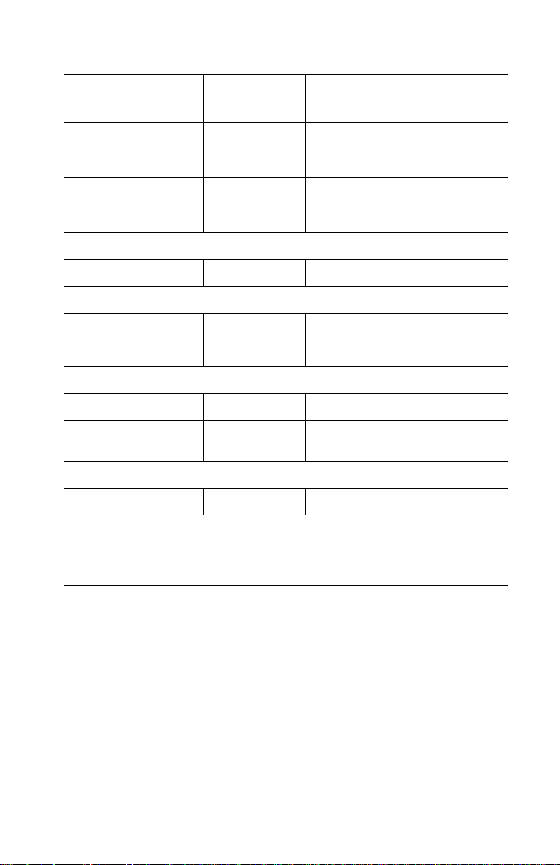
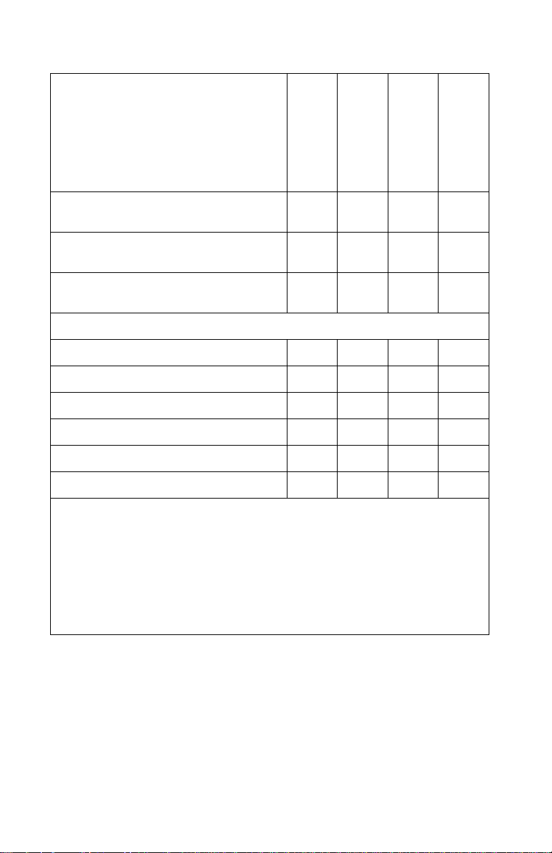
Model differences
C912
5055-230
28/29 ppm engine X X X X X
USB/parallel X X
USB/Ethernet X X X
Memory (MB) 256 256 128 64 64
Options available
550-sheet drawer X X X
Duplex X X
Hard disk X X
Staple and punch
finisher w/stand
Printer cabinet X X
XX
C912
5055-210
C912
5055-200
C910
5055-01N
5055-010
C910
General information 1-1
Page 18

5055-xxx
Technical specifications
Toner darkness
Toner darkness settings offer four user-selectable settings to
balance print darkness and toner savings. The higher the setting,
the darker the print. The toner darkness default setting is 4.
The toner darkness setting is available through the operator panel
under the Print Quality menu.
Color correction settings
There are four color correction settings to provide flexibility in
choosing the type of color correction to be applied when printing a
file.
• Auto (default)—provides ease of use with no color science
knowledge required
• Vivid—adjusts CMYK components, with the result being colors
that are more saturated
• Off—no color correction is implemented from RGB or CMYK
applications
• CMYK—provides the application's color correction instead of
the printer's algorithms
Black and White Lock—(in configuration menu) allows printer and
network administrators to lock the printer in a mode that will only
print black. This feature cannot be overridden with any other menu
or driver selection.
1-2 Service Manual
Page 19

5055-xxx
Physical specifications and weight
Description Height Width Depth Weight
Printers
Lexmark C91x
Lexmark C91xn
1
2,4
20.2 in.
(512 mm)
25.2 in.
(641 mm)
27.4 in.
(695 mm)
27.4 in.
(695 mm)
25.8 in.
(655 mm)
25.8 in.
(655 mm)
177 lb
(80.5 kg)
217.8 lb
(99.0 kg)
Lexmark C91xdn 25.2 in.
(641 mm)
Lexmark C91xfn
3
40.5 in.
(1028 mm)
Fully configured
4
40.5 in.
(1028 mm)
27.4 in.
(695 mm)
46.9 in.
(1191 mm)
60.0 in.
(1520 mm)
25.8 in.
(655 mm)
25.8 in.
(655 mm)
25.8 in.
(655 mm)
230.8 lb
(104.9 kg)
336.4 lb
(152.9 kg)
443.3 lb
(201.5 kg)
Options
Duplex unit 4.7 in.
(120 mm)
550-Sheet drawer 5.1 in.
(129 mm)
High-capacity f ee der,
3000-sheet
Staple Punch finisher,
1100-sheet
25.0 in.
(635 mm)
41.7 in.
(1060 mm)
27.4 in.
(695 mm)
27.4 in.
(695 mm)
14.2 in.
(360 mm)
19.5 in.
(495 mm)
13.8 in.
(350 mm)
25.8 in.
(655 mm)
20.7 in.
(525 mm)
20.5 in.
(520 mm)
13.0 lb
(5.9 kg)
40.8 lb
(18.5 kg)
50.0 lb
(22.6 kg)
56.9 lb
(25.9 kg)
(with stand)
Furniture
Printer cabinet 20.4 in.
(517 mm)
Printer base 10.2 in.
(260 mm)
1
Base model with standard 550-sheet input tray.
2
Network model is network-ready printer with standard 550-sheet input tray plus one
optional 550-sheet drawer.
3
Finisher model is a duplex model printer with 1100-sheet punch finisher and printer
cabinet.
4
Fully configured models include base printer with four standard 550-sheet input
trays, 3000-sheet feeder, 1100-sheet staple punch finisher, duplex unit, and printer
base.
26.6 in.
(675 mm)
26.6 in.
(675 mm)
23.6 in.
(598 mm)
23.6 in.
(547 mm)
57.5 lb
(26.0 kg)
33.0 lb
(15.0 kg)
General information 1-3
Page 20

5055-xxx
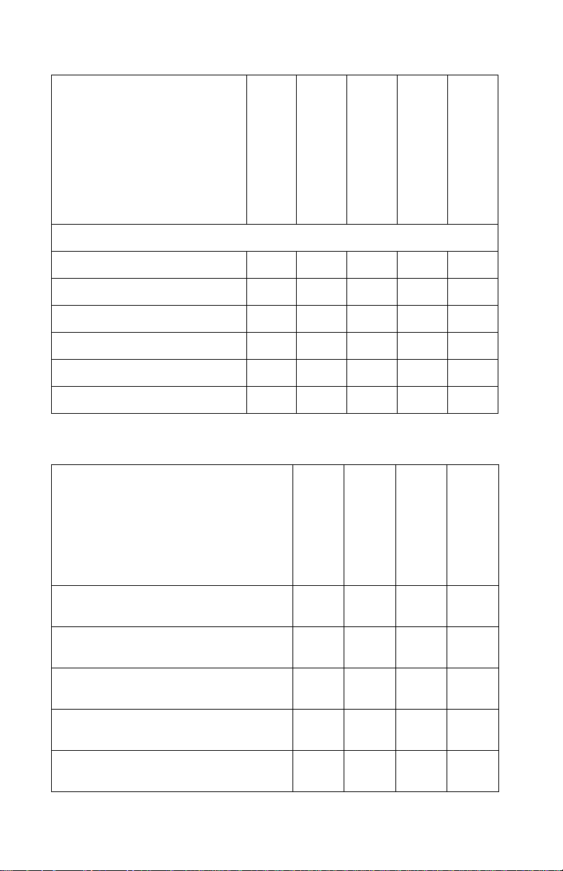
Print speed and performance
Standard and
heavy media
tray
Simplex printing on letter-size media (pages per minute)
Letter—8.5 in. x 11 in. 28 28 28
Ledger 16 N/A 16
Legal—8.5 in. x 14 in. 19 N/A 19
A3 16 N/A 16
A4—3.4 in. x 11.7 in. 29 29 29
A5/Executive N/A N/A 38
B4 18 N/A 18
B5 N/A N/A 32
Transparencies 22 N/A 22
Card stock N/A N/A 11
Envelopes N/A N/A 11
Paper labels 22 N/A 22
Duplex printing on letter-size media (sides per minute)
High-capacity
feeder
Multipurpose
feeder
1
1,2,3,4
Letter—8.5 in. x 11 in. 19 19 19
Ledger 11 N/A 11
Legal—8.5 in. x 14 in. 12 N/A 12
A3 11 N/A 11
A4—3.4 in. x 11.7 in. 19 19 19
A5/Executive N/A N/A 20
1-4 Service Manual
Page 21

5055-xxx
B4 12 N/A 12
B5 N/A N/A 19
1
Folio and statement paper support from multipurpose feeder only.
2
Speeds.
3
When printing from the multipurpose feeder: Simplex—the first three pages print a
“legal” speed with the balance printing at the speed consistent with the actual media
size. Duplex—all pages print at “legal” speed.
4
Average duple x print performance measured under the following conditions: Simplex
text document from the printer’s integrated tray to the printer’s standard output bin,
with a job stream sufficiently long for the printer system to enter the maximum
duplex print performance page sequence (2,4,6,1,3,5...) The first two sides (2 and 4)
are not included in the performance computation since they “seed” the printer
system’s paper path to achieve the maximum duplex print performance.
Performance
The Lexmark C91x printers support the speeds listed above.
Performance depends on:
• Interface to the host (USB, serial, parallel, network)
• Host system and application
• Page complexity and content
• Certain printer options installed or selected
• Printer memory
• Media size and type
Time to first print
Time to first print is 15 seconds.
Processor
• 400 MHz (C910)
• 600 MHz (C912)
Duty cycle
• Maximum duty cycle–100,000 pages
• True continuous duty cycle–10,000 pages
• Lifetime maximum duty cycle–600,000 pages
General information 1-5
Page 22

5055-xxx
Printer memory
Memory configuration
DRAM memory Standard Maximum
Lexmark C910(n) 64MB 512MB
Lexmark C910dn 128MB 512MB
Lexmark C912(n) 128MB 512MB
Lexmark C912(dn) 256MB 512MB
Available memory options
Optional 64MB, 128MB and 256MB SDRAM DIMMs are available
from Lexmark.
Flash memory options
Optional 4MB, 8MM and 16MB DIMMs are available from Lexmark.
Memory and expansion slots
• Memory slots for extra flash or DRAM
– Two for Lexmark C910(n) and Lexmark C912(n)
– One for Lexmark C910(dn) and Lexmark C912(dn)
• One expansion slot for optional interface cards
• One optional firmware expansion slots (application solution
firmware card)
• One on-board hard disk interface (for optional hard disk)
SDRAM and flash memory options are interchangeable within any of
the memory slots available on the system board. However, only one
flash memory Maintenance Approach option will be recognized. If
multiple flash memory options are installed, the system will
recognize the largest one.
1-6 Service Manual
Page 23

5055-xxx
Resident fonts
Emulation Scalable Fonts Bitmapped fonts
PCL 6 84 2
PostScript 3 156 0
For a listing of specific fonts, visit www.lexmark.com.
There are 83 symbol sets in the PCL 6 emulation to support all the
languages that use these characters.
Not all symbol sets are supported by all fonts. Refer to the Technical
Reference or use the printer operator panel to find which symbol
sets are supported by each font.
Support for the euro currency character is included in all applicable
fonts for both PostScript and PCL emulations. Twelve PCL symbol
sets support the euro character, including all seven Windows symbol
sets.
Additional fonts can be downloaded to the printer RAM, optional
Flash DIMM or hard disk. PCL emulation supports both scalable and
bitmapped downloadable fonts. PostScript emulation supports only
downloadable scalable fonts. Font cards and font cartridges are not
supported.
General information 1-7
Page 24

5055-xxx
Paper and media specifications
Capacity may vary and is subject to media specifications and printer
operating environment. Capacities listed are based on plain paper
at 75 g/m
Input and output configurations
2
.
Sources and
capacities
Input sources
Number of standard
sources
Optional input dra w ers 3 2 2
High-capacity feeder 1 1 1
Maximum number of
input sources
Input capacities (sheets)
Standard
Primary tray 550 550 550
Second tray N/A 550 550
Multipurpose tray 100 100 100
Total standard
capacity
Optional
500-sheet drawer 550 550 550
Heavy media tray
High-capacity feeder
Lexmark
C91x
233
666
650 1,200 1,200
1
2
Yes Yes Yes
3,000 3,000 3,000
Lexmark
C91xn
Lexmark
C91xdn
Maximum additional
drawers
1-8 Service Manual
322
Page 25
5055-xxx
Sources and
capacities
Maximum input
Lexmark
C91x
Lexmark
C91xn
2,300 2,300 2,300
Lexmark
C91xdn
capacity (without
high-capacity feeder)
Maximum input
5,300 5,300 5,300
capacity and
high-capacity feeder
Output destination
Number (standard) 1 1 1
Output capacities sheets
Standard output bin 550 550 550
Face-up bin 100 100 100
Optional
Finisher
3,4
Maximum output
1,000 1,000 1,000
1,650 1,650 1,650
capacity
Other
Duplex unit Yes Yes Standard
1
The heavy media tray is supported only as Tray 1 (top).
2
A maximum of one high-capacity input drawer is supported on any model.
3
A maximum of one finisher is supported on any model.
4
The finisher requires installation of the 2 x 550-sheet drawer with the base or printer
cabinet.
General information 1-9
Page 26

5055-xxx
Media size supported
Input
A4—8.27” x 11.7 in.
(210 mm x 297 mm)
A5—5.83” x 8.27 in.
(148 mm x 210 mm
JIS-B5—7.17 in.x 10.23 in.
(182 mm x 257mm)
JIS-B4—4.34 in. x 10.1 in.
(364 mm x 252 mm)
Letter—8.5 in. x 11 in.
(216 mm x 279 mm)
Legal—8.5 in. x 14 in.
(216 mm x 256 mm)
Executive—7.25 in. x 10.5 in.
(184 mm x 267 mm)
Tabloid—11 in. x 17 in.
(279.4 mm x 431.8 mm)
12 in. x 18 in.
(305 mm x 457 mm)
Lexmark C912 only
500-sheet input
XXXXX
XX XX
XXXXX
XX XX
XX XX
XX XX
multipurpose feeder
XXX
XX
XX
High-capacity feeder
Duplex
Heavy media tray
A3—11.69 in. x 16.54” in.
(297 mm x 420 mm)
1-10 Service Manual
XX XX
Page 27

5055-xxx
Universal
1,2
Banner 11.69 x 36 in.
(297.2 x 914.4 mm)
Lexmark C912 only
2.75 x 5 in. to 8.5 x 14 in.
(69.85 x 127 mm to 229 x
355.6 mm)
5.83 x 7.17 in. to 8.5 x 14 in.
(148 x 182 mm to 215.9 x
355.6 mm)
7 ¾ Envelope—3.875 in. x
7.5 in. (98 mm x 191 mm)
9 Envelope—3.875 in. x 8.9 in.
(98 mm x 225.4 mm)
10 Envelope—4.125 in. x
9.5 in. (105 mm x 241 mm)
DL Envelope—4.33 in. x
8.66 in. (110 mm x 220 mm)
C4 Envelope —9 in. x 12. 75 in.
(229 mm x 324 mm)
500-sheet input
multipurpose feeder
High-capacity feeder
Duplex
Heavy media tray
X
X
X
3
X
3
X
X
X
X
X
X
C5 Envelope—6.38 in. x
9.01 in. (162 mm x 229 mm)
B5 Envelope—6.93 in. x
9.84 in. (176 mm x 250 mm)
4
Other Envelope
—
11.69 in. x 11.69 in.
(297 mm to 297 mm)
X
X
X
General information 1-11
Page 28
5055-xxx
500-sheet input
multipurpose feeder
High-capacity feeder
Duplex
Heavy media tray
Media type
Paper XXXXX
Card stock X
Transparencies X
5
X
Envelopes X
Glossy paper X X
Paper labels X
6
7
XX
8
X
Output
A4—8.27 in. x 11.7 in.
(210 mm x 297 mm)
Standard output
XXXX
Bin 1
Finisher Bin 1
Finisher Bin 2
A5—5.83 in. x 8.27 in.
(148 mm x 210 mm
JIS-B5—7.17 in. x 10.23 in.
(182 mm x 257mm)
JIS-B4—14.34 in. x 10.1 in.
(364 mm x 252 mm)
Letter—8.5 in. x 11 in.
(216 mm x 279 mm)
1-12 Service Manual
XXX
XX
XXX
XXXX
Page 29

5055-xxx
Legal—8.5 in. x 14 in.
(216 mm x 256 mm)
Executive—7.25 in. x 10.5 in.
(184 mm x 267 mm)
Tabloid—11 in. x 17 in.
(279.4 mm x 431.8 mm)
12 in. x 18 in.
(305 mm x 457 mm)
Lexmark C912 only
A3—11.69 in. x 16.54 in.
(297 mm x 420 mm)
Universal
Banner 11.69 x 36 in.
(297.2 x 914.4 mm)
Lexmark C912 only
2.75 x 5 in. to 8.5 x 14 in.
(69.85 x 127 mm to 229 x 355.6 mm)
5.83 x 7.17 in. to 8.5 x 14 in.
(148 x 182 mm to 215.9 x 355.6 mm)
1,2
Standard output
XXX
XXX
XXX
XXX
XXX
X
Bin 1
X
X
Finisher Bin 1
X
X
Finisher Bin 2
7 ¾ Envelope—3.875 in. x 7.5 in.
(98 mm x 191 mm)
9 Envelope—3.875 in. x 8.9 in.
(98 mm x 225.4 mm)
10 Envelope—4.125 in. x 9.5 in.
(105 mm x 241 mm)
DL Envelope—4.33 in. x 8.66 in.
(110 mm x 220 mm)
C4 Envelope—9 in. x 12.75 in.
(229 mm x 324 mm)
X
X
X
X
XX
General information 1-13
Page 30
5055-xxx
Standard output
C5 Envelope—6.38 in. x 9.01 in.
Bin 1
Finisher Bin 1
XX
(162 mm x 229 mm)
B5 Envelope—6.93 in. x 9.84 in.
XX
(176 mm x 250 mm)
Other Envelope
—11.69 in. x 11.6 9 in .
XX
4
(297 mm to 297 mm)
Media type
Paper X X X X
Card stock XXX
Transparencies X X
Envelopes X X
Glossy paper X X X X
Paper labels X
1
When Universal is selected, the page is formatted for 8.5 x 14 in. (215.9 x 355.6
mm) unless the size is specified in the software application.
2
Narrow media should be loaded with the length in the feed direction (portrait).
3
A5 paper 5.83 x 8.27 in. (148 x 210 mm) is the smallest size the printer can duplex.
4
When Other Envelope is selected, the page is formatted for 8.5 x 14 in. (215.9 x
355.6 mm) unless the size is specified in the software application.
5
Maximum stack of 50 sheets; if more input is required, use Heavy Media Tray.
6
Manual feed (one sheet at a time) only; if more input is required, use Heavy Media
Tray.
7
Maximum st ack of 30 sheets; if more input is required, use Heavy Media Tray.
8
Refer to Cardstock & Label Guide for media guidelines.
X
Finisher Bin 2
1-14 Service Manual
Page 31

5055-xxx
Input media types and weights
Media Weight
Standard trays
1, 2, 3
Paper–xerographic or business 16 to 28 lb bond (60 to 105 g/m2)
Specialty papers–glossy laser 80 lb book (32 lb bond) (120 g/m
Heavy media tray1
Paper–xerographic or business 28 to 47 lb bond (105 to 176 g/m
Specialty papers–glossy laser4 80 lb book (32 lb bond) (120 g/m
Transparencies–laser printer type5 47 lb bond (175 g/m2)
2
Labels–upper limit paper 48 lb bond (180 g/m
Multipurpose feeder
1
)
Paper–xerographic or business 16 to 28 lb bond (60 to 105 g/m2)
Specialty papers–glossy laser 80 lb book (32 lb bond)(120 g/m
Card stock–upper limit Index
90 lb index (44 lb bond) (165 g/m
Bristol
2
Transparencies–laser printer type 47 lb bond (175 g/m
Labels–upper limit paper 48 lb bond (180 g/m
Envelopes–sulfite, wood -free, up to
100% cotton
High-capacity feeder
1
20 to 28 lb bond
2
)
g/m
)
2
)
2,3
(75 to 105
2
)
2
)
2
)
2
)
2
)
Paper–xerographic or business 16 to 28 lb bond (60 to 105 g/m2)
1
T he duplex option supports the same weights and types as the printer, except for
transparencies, envelopes, labels, and paper less than 80 g/m2 (21.3 lb bond) or
greater than 105 g/m
2
100% cotton content maximum weight is 90 g/m2 (24 lb bond)
3
105 g/m2 (28 lb bond) envelopes are limited to 25% cotton content
4
Part numbers 12A5950 (letter) and 12A5951 (A4)
5
Part numbers 12A5940 (letter) and 12A5941 (A4)
6
Refer to Cardstock & Label Guide for media guidelines.
2
(28 lb bond).
General information 1-15
Page 32

5055-xxx
Output media types and weights
Media Weight
Standard output
3
Paper–xerographic or business 16 to 28 lb bond (60 to 105 g/m2)
Specialty papers–glossy laser 80 lb book (32 lb bond) (120 g/m
Card stock–upper limit Index
90 lb index (44 lb bond) (165 g/m2)
Bristol
Transparencies–laser printer type 47 lb bond (175 g/m
2
)
Labels—upper limit paper 48 lb bond (180 g/m2)
3, 4
Bin 1
Paper–xerographic or business 16 to 28 lb bond (60 to 105 g/m2)
Specialty papers–glossy laser
Card stock–upper limit Index
1
80 lb book (32 lb bond) (120 g/m2)
90 lb index (44 lb bond) (165 g/m
Bristol
2
Transparencies–laser printer type
Labels–upper limit paper 48 lb bond (180 g/m
Envelopes–su lfite, wood -free, up to
100% cotton
Finisher bin 1
3,4
47 lb bond (175 g/m2)
20 to 28 lb bond
6,7,8
(75 to 105 g/m2)
2
)
2
)
2
)
Paper–xerographic or business 16 to 28 lb bond (60 to 105 g/m2)
Specialty papers–glossy laser
Card stock–upper limit Index
1
80 lb book (32 lb bond) (120 g/m2)
90 lb index (44 lb bond) (165 g/m
Bristol
2
Transparencies–laser printer type
Labels–upper limit paper 48 lb bond (180 g/m
47 lb bond (175 g/m2)
2
)
1-16 Service Manual
2
)
Page 33

5055-xxx
Media Weight
Finisher bin 2
3, 4, 5
Paper–xerographic or business 16 to 28 lb bond (60 to 105 g/m2)
1
Part numbers 12A5950 (letter) and 12A5951 (A4).
2
Part numbers 12A5940 (letter) and 12A5941 (A4).
3
The duplex option supports the same weights and types as the printer, except for
transparencies, envelopes, labels and paper less than 80 g/m
greater than 105 g/m
4
Bin 1 represents engine side output and Finisher Bin 1 (face-up).
5
F inisher supports hole punch, job offset and stapling.
6
Finisher only supports long-edge fed envelopes wider than 5.8 in. (148 mm)—feed
direction dimension.
7
100% cotton content maximum weight is 90 g/m2 (24 lb bond).
8
105 g/m2 (28 lb bond) envelopes are limited to 25% cotton content.
2
(28 lb bond).
2
(21.3 lb bond) or
General information 1-17
Page 34

5055-xxx
Input capacity by media and source
Media Stack height Capacity
500-Sheet trays
Plain paper (letter, A4,
legal, tabloid, A3)
Plain paper (letter, A4,
legal, tabloid, A3)
Glossy paper 0.6 in. (15 mm) 130 sheets
2.2 in. (5 6 mm) 550 sheets
20 lb (75 g/m
1 in. (25 mm)
240 sheets
24 lb (90 g/m
32 lb (120 g/ m
2
)
2
)
2
)
Multipurpose feeder
Plain paper
100 sheets
20 lb (75 g/m
2
)
Transparencies 50 transparencies
0.4 in. (11 mm)
Envelopes 10 envelopes
Card stock 55 sheets
90 lb index (163 g/m
Paper labels 55 sheets
up to 48 lb (180 g/m
Glossy paper (Manual) 1 sheet
32 lb (120 g/ m
2
)
High-capacity feeder
Plain paper 12.5 in. (317 mm) 3,000 sheets
20 lb (75 g/m
2
)
2
)
2
)
Heavy media tray
Plain paper 1.6 in. (40 mm) 300 sheets
32 lb (120 g/ m
Transparencies 0.8 in. (20 mm) 150 transparencies
47 lb (175 g/ m
Paper labels 1.6 in. (40 mm) 200 sheets
up to 48 lb (180 g/m
Glossy paper 1.6 in. (40 mm) 360 sheets
32 lb (120 g/ m
1-18 Service Manual
2
)
2
)
2
)
2
)
Page 35

5055-xxx
Output capacity by media and source
Media Stack heights Capacity
Standard output bin
Plain paper Varies 550 sheets
20 lb (75 g/m
Glossy paper Varies 130 sheets
32 lb (120 g/m
2
)
2
)
Bin 1 and Staple Punch Finisher Bin 1
Plain paper Varies 100 sheets
20 lb (75 g/m
Transparencies Varies 50 transparencies
47 lb (175 g/m
2
)
2
)
Bin 2—Staple Punch Finisher
Plain paper 6.0 in.
(152 mm)
1,000 sheets
20 lb (75 g/m
2)
Notes:
• Performance may vary subject to media specifications and printer
operating environment
• Media at ambient environment
• All media is letter/A4, unless otherwise noted
• All paper weights are stated in bond, unless otherwise noted
General information 1-19
Page 36

5055-xxx
Media guidelines
Paper
Following are media guidelines for successful printing:
• Rough, highly textured, limp or pre-curled papers will result in
lower print quality and more frequent paper feed failures.
• Colored papers, treated and preprinted papers, letterhead and
labels must be able to withstand 338° F (170° C) fusing
temperature.
• Preprinted forms and letterhead should be selected using
guidelines found in the printer User's Guide. The chemical
process used in preprinting may render some papers
unsuitable.
• Unsuitable papers include multipart forms and documents;
chemically treated papers; coated, synthetic, and thermal
papers; and preprinted papers requiring a high degree of
registration.
• Recycled paper less than 21 lb (80 g/m
unacceptable results.
2
) may cause
Envelopes
• Envelopes should be fed long edge first, with flap trailing.
• When the finisher is attached, only long-edge fed envelopes
wider than 5.8 in. (148 mm) feed direction dimension may be
used. To print smaller envelopes, the finisher must be undocked
during the job.
• If envelope wrinkling occurs, refer to the User's Guide for correct
weight, type, loading and stacking of envelopes.
• All envelopes should be new, unused and without package
damage.
• Envelopes with excessive curl or twist exceeding 0.12 in.
(6 mm), stuck together, with bent corners or nicked edges or
those that interlock should not be used.
1-20 Service Manual
Page 37

5055-xxx
• Minimum weight: 20 lb (75 g/m
2
)
• The following envelopes should not be used:
– Envelopes with windows, holes, perforations, cutouts, deep
embossing or package damage
– Envelopes with metal clasps, string ties or metal folding bars
– Envelopes with exposed flap adhesive when the flap is in the
closed position
For best results, printing on new 24 lb (90 g/m
bond envelopes is recommended.
Note: Under high-humidity conditions (over 60%) the envelopes
may seal during printing.
Transparencies
Use letter (p/n 12A5940) or A4 (p/n 12A5941) only
Labels
Labels should be selected using guidelines found in the User's
Guide or the Cardstock and Label Guide, and tested for
acceptability.
Lexmark glossy paper
2
) sulfite or 25% cotton
• Use letter (p/n 12A5950) or A4 (p/n 12A5951) only
• Glossy paper is only supported from Tray 1, Multipurpose
Feeder, and Heavy Media Tray.
Print area
Printable area for the printer is to within 0.16 in. (4.2 mm) of all
edges of the media (except envelopes).
General information 1-21
Page 38

5055-xxx
Options and features
Lexmark C91x printers support only Lexmark C91x paper-handling
options. These options are not compatible with any other Lexmark
printer.
• 550-Sheet drawer—(includes 550-sheet tray and support unit)
installs beneath the printer and holds approximately 550 sheets
of 20 lb paper. Multiple optional drawers (up to 3) are supported
simultaneously.
• High-capacity feeder—is designed to provide an additional
input tray (Tray 3 or T ray 5, depending on the configuration) with
a total capacity of 3,000 sheets (plain paper—letter or A4—20
lb (75 g/m
and attaches to the right side of the printer.
• Heavy-media tray—is intended for special media such as
transparencies, labels and glossy paper. This is supported only
as Tray 1 (top drawer location).
• Duplex unit—offers two-side printing and is designed to
complement the Lexmark C91x printers.
• Finisher—offers stapling, hole punching, offset stacking and an
additional output bin. Two models are available. 3- or 4-hole leftedge hole punching is available. The single staple position is the
upper left corner. The finisher can support up to 1,100 sheets of
unstapled, unpunched media. For stapled media, the output bin
supports up to 30 stapled sets or 1,000 sheets. The stapler can
staple a maximum of 30 sheets per set. Each printer can
support a single finisher.
• Printer cabinet—is customer installable and attaches so the
printer sits on top of the printer stand. The printer cabinet raises
the printer to the correct height for use with the optional finisher
and high-capacity feeder. The printer cabinet and high-capacity
feeder can be installed at the same time.
– C91x – 1 optional drawer
– C91xn or dn – no optional drawers
2
). The high-capacity feeder is customer installable
1-22 Service Manual
Page 39

5055-xxx
• Printer base—is customer installable and attaches so the
printer sits on top of the printer base. If used with two optional
550-sheet drawers, the printer base raises the printer to the
correct height for use with the optional finisher and highcapacity feeder. The printer base and high-capacity feeder can
be installed at the same time.
– C91x –3 optional drawers
– C91xn and C91xdn –2 optional drawers
Connectivity
Standard
• Lexmark C91x
– Bidirectional parallel and USB
• Lexmark C91xn and Lexmark C91xdn
– 10/100BaseTX Ethernet and USB
Note: USB is supported only under Windows 98 SE, Windows Me,
Windows XP, Windows 2000 operating systems, Sun's Sun Ray
appliances running Sun Ray Server code version 1.2 or later, Sun
Blade workstations and Apple Macintosh iMac computer with
Operating System 8.6 or higher. A USB cable is included with this
card.
Optional internal local connections
• Tri-Port Adapter (RS-232/RS-422 Serial, LocalTalk and Infrared)
• RS-232C Serial/Parallel-C Interface Card
General information 1-23
Page 40

5055-xxx
Network connections
Internal network connections
• Lexmark MarkNet N2000 Serie s Internal Print Servers
– MarkNet N2000t for Token-Ring attachment
– MarkNet N2001e for Ethernet 10BaseT/100BaseTX
– MarkNet N2002e for Ethernet 10BaseT/10Base2
• Lexmark MarkNet N2003 Series Internal Fiber Print Servers,
including:
– MarkNet N2003fx SC
– MarkNet N2003fx MTRJ
External network connections
• MarkNet X2000 Series External Print Servers
– MarkNet X2011e (1-port) for Ethernet 10BaseT/100BaseTX
– MarkNet X2012e (1-port) for Ethernet 10BaseT/100BaseTX,
10BaseT/10Base2
– MarkNet X2031e (3-port) for Ethernet 10BaseT/100BaseTX
– MarkNet X2030t (3-port) for Token-Ring attachment
Standard Ethernet and MarkNet compatibility
The standard Ethernet connection, MarkNet N2000 series and
MarkNet N2003 series internal and MarkNet X2000 series external
print servers support NetPnP 7.0 or later on Windows NT 4.0,
Windows 2000 and Windows XP systems.
The Ethernet and Token-Ring print servers and the standard
Ethernet connection support the following protocols:
• TCP/IP
• Novell (IPX/SPX including NetWare Directory Services)
• AppleTalk
• LexLin k (DLC/LLC)
1-24 Service Manual
Page 41

5055-xxx
The TCP/IP standard set of application services is supported,
including DHCP, WINS, SNMP (industry standard printer MIB), http,
lpr/lpd, ftp, tftp, ping, finger, telnet, bootp and rarp. The following
protocols are also supported:
• IPP: Internet Printing Protocol
• SLP: Service Location Protocol
• NTP: Network Timing Protocol
Printers with standard Ethernet, MarkNet N2000 series and MarkNet
N2003 series internal print servers and MarkNet X2000 series
external print servers support a resident Web page with Microsoft
Internet Explorer 4.0 or later and Netscape Navigator 4.5 or later for
Windows 95, Windows 98, Windows Me, Windows 2000, Windows
XP or Windows NT. The remote operator panel is available using the
standard Ethernet connection, MarkNet N2000, MarkNet N2003 or
MarkNet X2000 Series external print servers installed in or used
with a Lexmark C91x pr in ter.
Data streams
• PostScript 3 Emulation
• Hewlett-Packard Company PCL 6 Emulation
Operating systems
These printers are compatible with applications running under the
previously mentioned operating systems for either local or network
connections.
General information 1-25
Page 42

5055-xxx
Power and electrical specifications
Power requirements
Average nominal power requirements for the base printer
configuration (110 volt). Power level are shown in watts.
Printing states (average
power)
Off 0 W * *
Average power while printing
Continuous mono
Continuous color
Average power while printing
Continuous mono
Continuous color
Average power while printing
Continuous mono
Continuous color
* 0 W. Always active and drawing voltage.
Nonnetwork
400 W
290 W
13 W
125 W
11 A
6 A
Network
400 W
290 W
14 W
125 W
11 A
6 A
Electrical specifications
Low volta ge models
• 110 to 127 V at 50 to 60 hertz (Hz) nominal
• 99 to 135 V, extreme
Duplex/
network
410 W
300 W
15 W
125 W
11 A
6 A
High voltage models
• 220 to 240 V at 50 to 60 hertz (Hz) nominal
• 198 to 254 V, extreme
Note: Using a 220 to 110 power converter with the 110 V printer is
not recommended.
1-26 Service Manual
Page 43

5055-xxx
Operating clearances
Dimension Measurement Notes
Left side 13 in. (330 mm) Clearance on the left side
Right
side
Front 26 in. (660 mm)
Rear 5 in. (127 mm)
Top 9 in. (229 mm) With the high-capacity feeder
C91x(n) 6 in. (152 mm) Clearance on right side should
C91xdn 13 in. (330 mm)
should be 9 in. (228.6) with
the finisher attached.
be 30 in. (762 mm) with the
high-capacity f ee der attached.
Clearance on the right side
should be 13 in. (330 mm)
with the duplex attache d, b u t
not the high-capacity feeder.
or finisher attached, the top
clearance needs to be 43.8 in.
(1,113 mm).
Environment
Printer temperature and humidity
Operating
• Temperature: 60 to 90° F (15.6 to 32.3° C)
• Relative humidity: 8 to 80%
• Maximum wet bulb temperature: 73° F (22.8° C)
• Altitude: 10,000 ft. (0 to 3,048 meters)
• Atmospheric pressure: 74.6 kPa
Power Off
• Temperature: 50 to 110° F (10 to 43.3° C)
• Relative humidity: 8 to 80%
• Maximum wet bulb temperature: 80.1° F (26.7° C)
• Altitude: 10,000 ft. (0 to 3,048 meters)
General information 1-27
Page 44

5055-xxx
Shipping printer without print cartridges
• Temperature: 0 to 140° F (0.6 to 60° C)
• Relative humidity: 5 to 100%
• Maximum wet bulb temperature: 85° F (30° C)
• Altitude: 34,000 ft. (10,300 meters)
Storing printer without print cartridges
• Temperature: 0 to 140° F (0.6 to 60° C)
• Relative humidity: 5 to 80%
• Maximum wet bulb temperature: 85° F (30° C)
• Altitude: 34,000 ft. (10,300 meters)
Shipping supply items
• Temperature: -40 to 104° F (-40 to 40° C)
• Relative humidity: 5 to 100%
• Maximum wet bulb temperature: 80° F (27° C)
Storing supply items
• Temperature: 0 to 104° F (0.6 to 40° C)
• Relative humidity: 5 to 80%
• Maximum wet bulb temperature: 80° F (27° C)
In some cases, performance specifications (such as paper OCF or
EP cartridge usage) are specified to be measured at an ambient
condition.
1-28 Service Manual
Page 45

5055-xxx
Maintenance approach
The diagnostic information in this manual leads you to the correct
field replaceable unit (FRU) or part. Use the error code charts,
symptom index, and service checks to determine the symptom and
repair the failure. The removals in the repair information chapter may
help you identify parts.
• “Printer messages” on page 2-4
• “Symptom table” on page 2-63
• “Service checks” on page 2-68
• “Repair information” on page 4-1
After you complete the repair, perform tests as needed to verify the
repair. See “Diagnostic aids” on page 3-1.
Standard inspection and cleaning procedure
• Switch off printer power, and disconnect the AC power cord
from the electrical outlet.
• Remove and inspect the photodevelopers and toner cartridges,
shielding them from strong light.
• Inspect the interior of the printer, removing foreign matter such
as paper clips, staples, pieces of paper or transparencies, paper
dust, hair, oil, grease, or toner.
• Clean the printer interior using a lint-free cloth, dampened
slightly with cold water. Do not use solvents or chemical
cleaners to clean the printer interior.
• Use only the specified oil or lubricant on printer parts (some
service parts are lubricated at the factory).
• Inspect and, if necessary, clean all rubber/plastic and D rolls
with a lint-free cloth, dampened slightly with cold water. Dry the
rolls with a lint-free cloth.
• While cleaning, inspect the interior of the printer for damaged
wires, loose connections, toner leakage, loose springs, and
damaged or worn parts.
• Be sure the printer is on a single, flat, strong table or desk top.
General information 1-29
Page 46

5055-xxx
• Inspect all supplies (OCR, cartridges, photodevelopers/toner
cartridges, belts, fuser CRUs) and paper sources (cassettes,
trays, feeders, duplex drawers, finishers, mailbox trays) for
obvious damage and proper installation (paper under corner
bucklers, paper guides not too tight). Inspect for correct media
usage (paper, transparencies, labels).
• Print a Demo page.
• If additional paper sources are installed, print a Demo page
from each of these, (if possible).
Note: Failure to print from an additional tray or feeder may imply
one or more pins are bent in the mating connector.
Return parts
Engineering periodically analyzes returned parts for failure modes.
Include a printed test (DEMO) page, before and after the repair, and
tag any returnable parts with a description of the failure.
Service recommendations
Before leaving the printer check the following:
• Be sure printer is on a flat, level, strong tabletop or level floor.
This is very important for color printers that use belts. Check
and set registration as necessary.
• Shake all cartridges and be sure they are correctly installed and
fully seated.
• While the cover is open, wipe any residual toner from the LEDs
using a lint free cloth.
• If you have serviced the finisher option, and in the process
pulled it away from the printer during repair, ensure that it is
properly aligned with the printer.
1-30 Service Manual
Page 47

5055-xxx
Tools
The removal and adjustment procedures require the following tools
and equipment:
• Magnetic tip Phillips screwdrivers, large and small
• Flat-blade screwdrivers
• Analog volt ohmmeter (a digital volt ohmmeter may also be
used)
• Needle nose pliers
• Tweezers, C-ring pliers
• Magnifier (20 times or highe r)
• 6-angle wrench (1.5 mm)
When you make voltage readings, always use frame ground unless
another ground is specified.
General information 1-31
Page 48

5055-xxx
Serial number, configuration ID, and part number
Open the front door. The serial number, configuration ID, and part
number are located as shown. The serial number is also on the
menu settings page you can print from the Tests Menu.
Serial Number
Config ID
P/N
1-32 Service Manual
Page 49

5055-xxx
Abbreviations
ASIC Application-specific integrated circuit
CSU Customer setup
DRAM Dynamic random access memory
EP Electrophotographic process
EPROM Erasable programmable read-only memory
ESD Electrostatic discharge
FRU Field replaceable unit
HVPS High voltage power supply
LAN Local area network
LASER Light amplification by stimulated emission of
radiation
LCD Liquid crystal display
LED Light-emitting diode
LVPS Low voltage power supply
NVRAM Nonvolatile random access memory
OEM Original equipment manufacturer
PICS Problem isolation charts
PIXEL Picture element
POR Power-on reset
POST Power-on self test
PQET Print quality enhancement technology
RIP Raster image processor
ROS Read-only storage
SRAM Static random access memory
UPR Used parts replacement
V ac Volts alternating current
V dc Volts direct current
General information 1-33
Page 50

5055-xxx
1-34 Service Manual
Page 51

5055-xxx
2. Diagnostic information
The diagnostic information in this chapter leads you to the failing
part. Before you replace an entire assembly, determine if just the
defective part is available in the parts catalog. Use the error code
tables, symptom table, service checks and the diagnostic aids
chapter to determine the symptom and repair the failure. The
removal procedures in the Repair information chapter may help you
identify parts. After you complete the repair, perform the appropriate
tests to verify the repair.
If an error is displayed, locate it in the “Service error message
tables” on page 2-4, the “Attendance messages” on page 2-34,
or the “Symptom table” on page 2-63 and take the appropriate
action.
If an error message appears while you are working on the printer, go
to the error message table and take the indicated action.
Adjustments and procedures following parts replacement
Note: When troubleshooting, or prior to making any adjustment to
print quality, always be sure:
• The printer is installed on a level rigid surface.
• The photodevelopers are never exchanged. Do not exchange a
black photodeveloper for a color photodeveloper, as they have
different surface phase counts.
• The Alignment Page is used when adjusting print registration.
Whenever you replace any of the following parts be sure to perform
the required adjustments or procedures. The adjustments are in the
Repair information and Diagnostic aids chapters.
Diagnostic information 2-1
Page 52

5055-xxx
Printer controller board/printer control EPROM (U5)
If you replace the printer controller board, remove EPROM (U5) and
install it on the new board. Also check the printhead alignment.
If you change the EPROM, record and input the following items
using the diagnostic mode following EPROM replacement:
• LED Printhead Light Quantity
• Printer Alignment (X, Y, and Theta)
• All Counters
RIP controller board
If you replace the RIP controller board, move the solid state drive,
memory, and option cards from the old card to the new one. After
replacing the RIP controller board, it is necessary to type in the
following items in Diagnostic Mode:
• Set Serial Number
• Configuration ID
Transfer belt
If you replace the transfer belt, check the printer alignment (X, Y, and
Theta), adjusted in diagnostic mode.
LED printhead controller board or LED printhe ad
If you replace the LED printhead controller board or LED printhead,
check and adjust the following items in diagnostic mode:
• LED Printhead Light Quantity
• Printer Alignment (X, Y, and Theta)
2-2 Service Manual
Page 53

5055-xxx
Start
Initial check
Before you start troubleshooting, check the following:
Installation environment
• The power supply line voltage is plus or minus 10% of the rated
line voltage.
• The machine is securely installed on a level surface in a well-
ventilated place.
• The room temperature is between 10 and 32°C (50 and 90°F)
and the relative humidity between 20 and 80%.
• Avoid sites generating ammonia gas, high temperature, high
humidity (near water faucets, kettles, humidifiers), cold spaces,
near open flames, and dusty areas.
• Avoid sites exposed to direct sunlight.
Print paper checks
• Use the recommended paper for this printer.
• Paper dampness. Make a trial print with paper from a newly
opened package, and check the result.
Diagnostic information 2-3
Page 54

5055-xxx
Printer messages
The printer displays three types of messages: service messages,
status messages, and attendance messages. Service messages
indicate a problem that requires a service technician. Status
messages provide information about the current state of the printer,
requiring no action. Attendance messages alert the operator to
printer problems that require operator intervention.
Service error message tables
900 - Unrecoverable Software Error
910 Service
Motor Error
910 - Drive Motor Error
Step Questions/actions Yes No
1 Are connectors CN1 and
CN5 on the motor drive
board connected properly?
2 Is connector CN33 on the
printer controller board
connected properly?
3 Did replacement of the
motor drive board solve the
problem?
4 Did replacement of the
printer controller board
solve the probl em ?
5 Did replacement of the
supplies solve the problem?
2-4 Service Manual
Go to step 2. Connect CN1
and CN5.
Replace th e
motor drive
board and go to
step 3.
Problem solved. Replace the
Problem solved. Replace all the
Problem solved. Replace the
Connect CN33.
printer controller
board and go to
step 4.
supplies and go
to step 5.
drive motor.
Page 55

5055-xxx
911 - Paper Exit Motor Error
Step Questions/actions Yes No
1 Is connector CN4 on the
printer controller board
securely connected?
2 Did replacement of the
paper exit motor solve the
problem?
Replace th e
paper exit motor
and go to step 2.
Problem solved. Replace the
Plug the
connector in
securely.
printer controller
board.
912 - High-Capacity Feed Motor Error
Step Questions/actions Yes No
1 Is connector CN40 on the
printer controller board
securely connected?
Go to “High-
capacity feeder
(HCF) service
check” on
page 2-70.
Plug the
connector in
securely.
917 - RIP Fan Error
917 Service
Fan Error
Step Questions/actions Yes No
1 Is connector J5 on the RIP
board connected properly?
2 Is 24 V dc present bet ween
pins 1 and 3 of connector
J5 on the RIP board?
3 Is 24 V dc present bet ween
pin 80 of the RIP/pri nter
controller and ground?
Go to step 2. Properly connect
J5.
Replace the RIP
fan.
Replace the RIP
board.
Go to step 3.
Replace the
printer controller
board.
Diagnostic information 2-5
Page 56

5055-xxx
918 - Main Unit Fan Error
Step Questions/actions Yes No
1 Is +24 V present between
pins 1 and 3 on connectors
CN17 (upper left fan) and
CN5 (upper right f an) on the
printer controller board?
Replace th e
failing fan.
Replace the
printer controller
board.
919 - Power Supply Fan Error
Step Questions/actions Yes No
1 Is +24 V present between
pins 1 and 3 of connector
CN6 on the printer
controller board?
Replace th e
power supply
fan.
Replace the
printer controller
board.
92x Service
Fuser Error
920 - Fuser Error—Fuser Heater Trouble
Step Questions/actions Yes No
1 Replace the fuser. Did this
fix the problem?
2 Did replacing power supply
2 fix the problem?
2-6 Service Manual
Problem solved. Return the fuse r,
replace the
power supply 2
and go to step 2.
Problem solved. Return power
supply 2 and
replace the
printer controller
board.
Page 57

5055-xxx
923 - Upper Fuser Thermistor Open Error
Step Questions/actions Yes No
1 Is connector CN44 on the
printer controller board
connected properly?
2 Is error 923 displayed? Power off and
3 Power the printer off and
short pins 1 and 4 of CN44
and power on. Is error 923
displayed?
Disconnect
CN44 and turn
the printer on.
Go to step 2.
reconnect CN44.
Go to step 3.
Replace th e
fuser.
Plug the
connector in
securely.
Replace the
printer controller
board.
Replace the
printer controller
board.
924 - Lower Fuser Thermistor Open Error
Step Questions/actions Yes No
1 Turn off the printer and
reinstall the fuser, making
sure it clicks into place.
Turn on the printer.
Did this resolve the
problem?
Problem solved Go to step 2
2 Is connector CN44 on the
printer controller board
connected properly?
3 Is error 924 displayed? Turn the printer
4 Turn off the printer and
short pins 8 and 11 of
CN44. Turn on the printer.
Is error 924 displayed?
Disconnect
CN44 and turn
the printer on.
Go to step 3.
off and
reconnect CN44.
Go to step 4.
Replace th e
fuser.
Diagnostic information 2-7
Plug the
connector in
securely.
Replace the
printer controller
board.
Replace the
printer controller
board.
Page 58

5055-xxx
925 - HVU Error
Step Questions/actions Yes No
1 Has the high voltage power
board (HVU) been
removed/replaced?
2 Is connector CN42 on the
printer controller board
connected properly?
3 Did replacing the printer
controller board fix the
problem?
Inspect the
secondary card
on the high
voltage board
(HVU) for a
broken
component
(Q906). Replace
the high voltage
board (HVU) if
necessary.
Replace th e
printer controller
board.
Go to step 3.
Problem solved. Replace the high
Go to step 2
Plug the
connector in
securely.
voltage power
board (HVU).
2-8 Service Manual
Page 59

5055-xxx
926(K), 927(C), 928(Y), 929(M) - Toner Sensor Error
92x Service
Toner Sensor
Step Questions/actions Yes No
1 Is the toner cartridge the
correct type for the printer?
2 Is the toner cartridge
encoder wheel dirty?
3 Replace the t one r c artridge
for the color with the error.
Did this fix the problem?
4 Test the sensors.
While actuating the sensor,
does the voltage fluctuate
between 0 V and +5 V
between pins 1 and 2 on
connectors CN22(K),
CN21(Y), CN18(M), and
CN19(C) on the printer
controller board?
Go to step 2. Recommend the
customer
replace the
cartridge with
the correct type.
Clean the
encoder wheel
and toner
sensor.
Problem solved. Go to step 4.
Replace th e
printer controller
board.
Go to step 3.
Replace the
affected toner
sensor.
Diagnostic information 2-9
Page 60

5055-xxx
930 - Yellow Printhead Error
930 Service
Printhead Error
Step Questions/actions Yes No
1 Check to ensure that the
cables between the LED
printhead and the printhead
controller board as well as
the cables between the
printhead controller board
and the printer controller
board are properly
connected.
Are they properly
connected?
2 For serial number
XX–0XXXX: Is fuse 5 on
the printhead control board
open?
3 Did replacement of the
printhead controller board
correct the problem?
4 For serial number
XX–1XXXX and above:
Replace the LED printhead
for the affected color.
If you have a
printer with serial
number
XX–0XXXX, go
to step 2.
If you have a
printer with serial
number
XX–1XXXX and
above, go to
step 4.
Replace th e
printhead control
board, cables
(CL13, CL24),
and LED
printhead.
Problem solved. Replace the
Problem solved. Replace the
Properly connect
the cables.
Replace the
printhead
controller board
and go to step 3.
printer controller
board.
printhead
controller board
and go to step 5.
Did this resolve the
problem?
5 Did replacement of the
printhead controller board
resolve the problem?
2-10 Service Manual
Problem solved. Replace the
printer controller
board.
Page 61

5055-xxx
931 - Magenta Printhead Error
Step Questions/actions Yes No
1 Check to ensure that the
cables between the LED
printhead and the print head
controller board as well as
the cables between the
printhead controller board
and the printer controller
board are properly
connected. Are they
properly connected?
2 For serial number
XX–0XXXX: Is fuse 6 on
the printhead control board
open?
3 Did replacement of the
printhead controller board
correct the problem?
4 For serial number
XX–1XXXX and above:
Replace th e LED printhead
for the affected color.
If you have a
printer with serial
number
XX–0XXXX, go
to step 2.
If you have a
printer with serial
number
XX–1XXXX and
above, go to
step 4.
Replace th e
printhead control
board, cables
(CL13, CL24),
and LED
printhead.
Problem solved. Replace the
Problem solved. Replace the
Properly connect
the cables.
Replace the
printhead
controller board
and go to step 3.
printer controller
board.
printhead
controller board
and go to step 5.
Did this resolve the
problem?
5 Did replacement of the
printhead controller board
resolve the problem?
Problem solved. Replace the
printer controller
board.
Diagnostic information 2-11
Page 62

5055-xxx
932 - Cyan Printhead Error
Step Questions/actions Yes No
1 Check to ensure that the
cables between the LED
printhead and the printhead
controller board as well as
the cables between the
printhead controller board
and the printer controller
board are properly
connected.
Are they properly
connected?
2 For serial number
XX–0XXXX: Is fuse 3 on
the printhead control board
open?
3 Did replacement of the
printhead controller board
correct the problem?
4 For serial number
XX–1XXXX and above:
Replace the LED printhead
for the affected color.
If you have a
printer with serial
number
XX–0XXXX, go
to step 2.
If you have a
printer with serial
number
XX–1XXXX and
above, go to
step 4.
Replace th e
printhead control
board, cables
(CL13, CL24),
and LED
printhead.
Problem solved. Replace the
Problem solved. Replace the
Properly connect
the cables.
Replace the
printhead
controller board
and go to step 3.
printer controller
board.
printhead
controller board
and go to step 5.
Did this resolve the
problem?
5 Did replacement of the
printhead controller board
resolve the problem?
2-12 Service Manual
Problem solved. Replace the
printer controller
board.
Page 63

5055-xxx
933 - Black Printhead Error
Step Questions/actions Yes No
1 Check to ensure that the
cables between the LED
printhead and the print head
controller board as well as
the cables between the
printhead controller board
and the printer controller
board are properly
connected.
Are they properly
connected?
2 For serial number
XX–0XXXX: Is fuse 4 on
the printhead control board
open?
3 Did replacement of the
printhead controller board
correct the problem?
4 For serial number
XX–1XXXX and above:
Replace th e LED printhead
for the affected color.
If you have a
printer with serial
number
XX–0XXXX, go
to step 2.
If you have a
printer with serial
number
XX–1XXXX and
above, go to
step 4.
Replace th e
printhead control
board, cables
(K13, K24), and
LED printhead.
Problem solved. Replace the
Problem solved. Replace the
Properly connect
the cables.
Replace the
printhead
controller board.
printer controller
board.
printhead
controller board
and go to step 5.
Did this resolve the
problem?
5 Did replacement of the
printhead controller board
resolve the problem?
Problem solved. Replace the
printer controller
board.
Diagnostic information 2-13
Page 64

5055-xxx
934 - Color Drum Sensor Error
934 Service
Drum Sensor
Step Questions/actions Yes No
1 Is connector CN28
connected properly?
2 Clean the color drum
sensor LED.
Did this fix the problem?
3 Did replacing the color
drum sensor fix the
problem?
Go to step 2. Plug the
connector in
securely.
Problem solved. Replace the
color drum
sensor.
Go to step 3.
Problem solved. Replace the
printer controller
board.
935 - Black Drum Sensor Error
Step Questions/actions Yes No
1 Is connector CN27
connected properly?
2 Clean the black drum
sensor LED. Did this fix the
problem?
Go to step 2. Plug the
connector in
securely.
Problem solved. Replace the
black drum
sensor.
Go to step 3.
3 Did replacing the black
drum sensor fix the
problem?
2-14 Service Manual
Problem solved. Replace the
printer controller
board.
Page 65

5055-xxx
936 - 939 Cassette Error
936 Service
Paper Option
Step Questions/actions Yes No
1 Are connectors CN35 and
CN36 on the printer
controller board connected
properly?
Replace th e
printer controller
board.
Plug the
connector in
securely.
940 - High-Capacity Feed Sensor Error
Step Questions/actions Yes No
1 Is connector CN40 on the
printer controller board
connected properly?
Go to “High-
capacity feeder
(HCF) service
check” on
page 2-70.
Plug the
connector in
securely.
941 - High-Capacity Feed Tray Error
Step Questions/actions Yes No
1 Is connector CN40 on the
printer controller board
connected properly?
Go to “High-
capacity feeder
(HCF) service
check” on
page 2-70.
Plug the
connector in
securely.
Diagnostic information 2-15
Page 66

5055-xxx
942 - Duplex Error
942 Service
Duplex
Step Questions/actions Yes No
1 Is connector CN37 on the
printer controller board
connected properly?
Replace th e
printer controller
board.
Plug the
connector in
securely.
945 - Engine Flash Error
945 Service
Engine Flash
Reflash the engine code.
946 - Printer/Printhead Controller Board Communication Error
946 Service
Communication
Step Questions/actions Yes No
1 Make sure all printhead
LED EPROMS are pr esent
on the printhead controller
board.
Are all the EPROMS
present?
Go to step 2 Install the
EPROM(s)
included with
printhead FRU.
2 Replace the printhead
controller board.
Did this fix the problem?
2-16 Service Manual
Problem solved. Replace the
printer controller
board.
Page 67

5055-xxx
947 - Finisher Communication Error
Step Questions/actions Yes No
1 Are the finisher to printer
interface cable and power
cable properly connected?
2 Replace the interf ace cable .
Did this resolve the
problem?
3 Did finisher control board
replacement resolve the
problem?
Go to step 2. Properly connect
the cable.
Problem solved. Replace the
control finisher
board. Go to
step 3.
Problem solved. Replace the
printer control
board.
948 - Machine ID Error
948 Service
Machine ID
Step Questions/actions Yes No
1 Turn the printer off and wait
30 seconds. Turn the printer
on. Did this fix the problem?
Problem solved. Verify proper
installation of the
EPROMs on
both the printer
controller board
and the
printhead
controller board.
Go to step 2.
2 Are the EPROMs installed
correctly?
3 Did replacing the printer
controller board fix the
problem?
Replace th e
printer controller
board.
Go to step 3.
Problem solved. Replace the
Install the
EPROMs
correctly.
printhead
controller board.
Diagnostic information 2-17
Page 68

5055-xxx
949 - Tray (x) Comm
Step Questions/actions Yes No
1 Replace the printer
controller board.
Does this fix the problem?
Problem solved. Replace the
expansion
feeder control
board for trays
2-5.
If the problem is
with the highcapacity paper
feeder, replace
the HCPF board.
950 - Pr Control Board
Replace the printer controller board.
952 - NVRAM Chip Failure
952 Service
NVRAM Failure
Step Questions/actions Yes No
1 Make sure the 80-pin RIP
printer controller cable is
not broken or damaged.
Replace th e
cable.
Go to step 2.
Is the cable broken or
damaged?
2 Is EPROM U5 present on
the printer controller board?
954 - NVRAM CRC Failure
Replace the RIP board.
2-18 Service Manual
Replace th e
printer controller
board.
Install EPROM
U5
Page 69

5055-xxx
955 - Code CRC
955 Service
Code CRC <loc>
Replace the RIP board.
956 - Processor Failure
956 Service
System Board
Replace the RIP board.
957 - ASIC Failure
Replace the RIP board.
958 - NAND Failure
958 Service
NAND Failure
Replace the RIP board.
960 - RAM Slot 1 Bad
960 Service
RAM Memory Error
Replace the RAM card or the RIP board.
961 - RAM Slot 2 Bad
Replace the RAM card or the RIP board.
962 - RAM Slot 3 Bad
Replace the RAM card or the RIP board.
964 - Emulation Error
964 Service
Emulation Error
Replace the DLE board. If this does not fix the problem, replace the
RIP board.
Diagnostic information 2-19
Page 70

5055-xxx
970 - Standard Network Error
970 Service
Standard Network
970 Service
Network Card x
Check the network card in slot x on the RIP card.
975 - Unrecognizable Network Port
Software error.
976 - Unrecoverable Software Error in Network Port
Software error. Go to the “Options service check” on page 2-98
and refer to the network card option section.
978 - Bad Checksum While Pro gramming Net work Card
Software error.
979 - Flash Parts Failed While Programming Network Port
Reflash network port.
2-20 Service Manual
Page 71

5055-xxx
980 - Face Up/Down Switching Error
980 Service
Switch Error
Check Area
B
Step Questions/actions Yes No
1 Does the F ac e Up/ Down
(FU/FD) deflector move at
all during power up?
2 Manually operate the FU/
FD deflector .
Does it properly lock int o
position when manually
operated?
3 Is there continuity on the
FU/FD deflector solenoid
between pins 1 and 2 of
CN14 on the printer
controller board?
4 Make sure that the FU/FD
deflector pivot arm is in the
proper position.
Is it in the proper position
with its operating linkage?
5 Is fuse 1 on the printer
controller board open?
Go to step 2. Go to step 3.
Go to step 3. Go to step 4.
Go to step 5. Replace the FU
exit assembly.
Replace th e FU
exit assembly.
Replace th e
printer controller
board and drum
eraser cable
assembly.
Place the FU/FD
pivot arm in the
proper position.
Replace the
printer controller
board.
Diagnostic information 2-21
Page 72

5055-xxx
981 - Belt Up/Down Sensor Error
981 Service
Switch Error
Step Questions/actions Yes No
1 Is engine code level 41D or
above.
2 Are connectors CN409 and
CN407 on the sensor board
connected properly?
3 Are connectors CN26 and
CN29 on the printer
controller board connected
properly?
4 Remove the transfer belt.
Verify the belt up/down
sensor actuator flag is
properly installed, not
broken, and in the proper
position. Make sure the
sensor is fully snapped in
place and that the sensor
connector is fully seated.
Are these items correct?
Go to step 2. Update the
printer with code
lev el 41D or
above.
If this dies not
resolve the
problem,
continue with
step 2.
Go to step 3. Plug the
connectors in
securely.
Go to step 4. Plug the
connector in
securely.
Go to step 5. If the sensor is
out of position or
disconnected,
properly install
the sensor and
securely connect
the sensor
connector.
If the sensor
actuator flag is
broken, replace
the belt up/down
changing shaft.
5 Clean the b elt up/down
sensor. Does this fix the
problem?
2-22 Service Manual
Problem solved. Go to step 5.
Page 73

5055-xxx
Step Questions/actions Yes No
6 Test the sensor. While
actuating the sensor, does
the voltage fluctuate
between 0 V and +5 V
between pins 7 and 8 of
connector CN29 on the
printer controller board?
7 Did replacing the belt up/
down clutch fix the
problem?
Replace th e belt
up/down clutch.
Go to step 7.
Problem solved. Replace the
Replace the belt
up/down sensor.
printer controller
board.
982 - Sensor Controller Error
982 Service
Sensor Control
Step Questions/actions Yes No
1 Turn the printer off and wait
30 seconds. Turn the printer
on.
Is error 982 displayed?
Replace the
printer
controller
board.
Problem
solved.
Diagnostic information 2-23
Page 74

5055-xxx
983 - Black Gear Sensor Error
983 Service
Gear Sensor
Step Questions/actions Yes No
1 Is connector CN20 on the
printer controller board
connected properly?
2 Check the cable running to
CN20 for damage.
Is the cable damaged?
3 Clean the gear sensor.
Does this correct the
problem?
4 Replace the sensor card.
Did this resolve the
problem?
Go to step 2. Plug the
connector in
securely.
Replace th e
cable.
Problem solved. Go to step 4.
Problem solved. Replace the
Go to step 3.
drive unit.
984 - Yellow Gear Sensor Error
Step Questions/actions Yes No
1 Is connector CN20 on the
printer controller board
connected properly?
2 Check the cable running to
CN20 for damage.
Is the cable damaged?
Go to step 2. Plug the
connector in
securely.
Replace th e
cable.
Go to step 3.
3 Clean the gear sensor.
Does this correct the
problem?
4 Replace the sensor card.
Did this resolve the
problem?
2-24 Service Manual
Problem solved. Go to step 4.
Problem solved. Replace the
drive unit.
Page 75

5055-xxx
985 - Transfer Belt Thermistor Error
985 Service
Thermistor Error
Step Questions/actions Yes No
1 Are connectors CN407 and
CN408 on the sensor board
connected properly?
2 Is connector CN29 on the
printer controller board
connected properly?
Go to step 2. Plug the
connector in
securely.
Replace th e
transfer b elt unit.
If the problem
remains, replace
the printer
controller board.
Plug the
connector in
securely.
986 - Transparency (OHP) Sensor Error
986 Service
OHP Sensor
Step Questions/actions Yes No
1 Are connectors CN15 (light
emitting) and CN7 (light
receiving) on the printer
controller board connected
properly?
2 Test the sensor. While
actuating the sensor, does
the voltage fluctuate
between 0 V and +5
between pins 2 and 3 of
connector CN7 of the
printer controller board?
Go to step 2. Plug the
connector in
securely.
Replace th e
printer controller
board.
Replace the
upper and lower
transparency
sensor.
Diagnostic information 2-25
Page 76

5055-xxx
992 - Temperature/Humidity Sensor Error
Step Questions/actions Yes No
1 Is connector CN3 on the
printer controller board
connected properly?
2 Replace the temperature
and humidity sensor (a
component of the paper
feed solenoid assembly).
Did this fix the problem?
993 CPU Error
Replace the printer controller board.
Go to step 2. Plug the
connector in
securely.
Problem solved. Replace the
printer controller
board.
2-26 Service Manual
Page 77

5055-xxx
994 - Density Sensor Error
Step Questions/actions Yes No
1 Is the front door fully
closed?
2 Is the density sensor
actuator stuck in place?
3 Are connectors CN406 and
CN407 on the sensor board
connected properly?
4 Is connector CN29 on the
printer controller board
connected properly?
5 Did replacing the density
sensor fix the problem?
Go to step 2. Close the front
door.
Release th e
density sensor
actuator.
Go to step 4 Plug the
Replace th e
density sensor.
Go to step 5.
Problem solved. Replace the
Go to step 3.
connector in
securely.
Plug the
connector in
securely.
printer controller
board.
Diagnostic information 2-27
Page 78

5055-xxx
995 - Finisher Main Feed Motor abnormal
995 Service
Finisher
Step Questions/actions Yes No
1 Is there jammed paper or
other obstructions in the
paper path?
2 Check to ensure the
connector PJ6 on the
finisher control board and
the feed motor assembly
cable are properly
connected. Are the cables
properly connected?
3 Make sure the finisher set
switch is activated.
Measure for +24 V dc
(±10%) between pins 7 an d
8 and +5 V dc (±10%)
between pins 7 and 6 on
the feed motor assembly
cable connector CN1. Is
either voltage missing?
4 Disconnect the feed motor
assembly ca b le and PJ6 o n
the finisher control board.
Measure continuity on the
cable for all positi ons. Is
there continuity?
Clear the paper
path.
Go to step 3. Properly connect
Go to step 4. Go to step 5.
Go to step 6. Replace the
Go to step 2.
the cables.
cable.
5 Replace the feed motor
assembly. Did this resolve
the problem?
2-28 Service Manual
Problem solved. Replace the
finisher control
board.
Page 79

5055-xxx
Step Questions/actions Yes No
6 Measure for +24 V dc
between pins 1 and 2 on
connector PJ3 on the
finisher control board.
Measure for +5 V dc
between pins 1 and 3 on
PJ2 on the finisher control
board. Is either voltage
missing?
Replace th e
power supply.
Replace the
finisher control
board.
Diagnostic information 2-29
Page 80

5055-xxx
996 - Finisher Jogging Motor Error
Step Questions/actions Yes No
1 Are there foreign objects or
obstructions in the jogging
assembly?
2 Are the jogging motor
connectors CN2 on the
finisher control board
securely connected?
3 Make sure the finisher set
switch is activated.
Measure for +24 V dc
(±10%) between pin 1 on
CN2 and frame ground. Is
+24 V dc present?
4 Replace the jogging motor
assembly. Did this resolve
the problem?
5 Disconnect CN2 and PJ5.
Perform a continuity check
on the cable for all
positions. Is there
continuity?
6 Check for +24 V dc (±10%)
between pins 1 and 2 of
PJ3 on the finisher control
board. Is +24 V dc present?
Clear the obje cts
or obstruction.
Go to step 3. Securely
Go to step 4. Go to step 5.
Problem solved. Replace the
Go to step 6. Replace the
Replace th e
finisher control
board.
Go to step 2.
connect the
connectors.
finisher control
board.
cable.
Replace the
power supply.
2-30 Service Manual
Page 81

5055-xxx
997 - Finisher Tractor Motor Error
Step Questions/actions Yes No
1 Are there obstructions or
foreign objec ts in the
accumulator or face down
paper path?
2 Are the connectors CN3 at
the tractor motor and PJ4
on the finisher control boar d
securely connected?
3 Make sure the finisher set
switch is activated.
Measure +24 V dc b etwee n
pin 1 of tractor motor
connector CN3 and frame
ground. Is +24 V dc
(±10%)?
4 Replace the tractor motor
assembly. Did this resolve
the problem?
5 Disconnect CN3 and PJ4
on the finisher control boar d
and perform a continuity
check on all positions. Is
there continuity on all
positions?
Remove the
objects or
obstructions.
Go to step 3. Securely
Go to step 4. Go to step 5.
Problem solved. Replace the
Go to step 6. Replace the
Go to step 2.
connect the
connectors.
finisher control
board.
cable.
6 Check for +24 V dc
between pins 1 and 2 of
PJ3 on the finisher control
board. Is +24 V dc present?
Replace th e
finisher control
board.
Replace the
power supply.
Diagnostic information 2-31
Page 82

5055-xxx
998 - Tray Elevator Motor Error
Step Questions/actions Yes No
1 Are the connectors CN4 at
the tray elevator motor and
connector PJ4 on the
finisher control board
properly connected?
2 Make sure that the finisher
set switch is activated.
Power the printer off.
Measure for appr oximately
+24 V dc (±10%) between
pins 1 and 2 of connector
CN4 at the tray elevator
motor . Power the printer on
and observe the voltage
meter during the first 12
seconds of power up. Is
+24 V dc present while the
printer is powering up?
3 Disconnect CN4 at the tray
elevator motor. Disconnect
PJ4 on the finisher control
board. Measure for
continuity between CN4 pin
1 and PJ4 pin 7. Measure
for continuity between CN4
pin 2 and PJ4 pin 8. I s there
continuity i n both locations?
Go to step 2. Properly connect
the connectors.
Replace th e tray
elevator motor.
Go to step 4. Replace the
Go to step 3.
cable.
4 Measure for +24 V dc
(±10%) between pins 1 an d
2 on connector PJ6. Is +24
V dc present?
2-32 Service Manual
Replace th e
finisher control
board.
Replace the
finisher power
supply.
Page 83

5055-xxx
999 - Stapler Motor Error
Step Questions/actions Yes No
1 Are staples jammed in the
stapler?
2 Clear the staple jam and
run the staple test in
diagnostic mode or run a
staple job. Does the
problem reoccur?
3 Are the connectors CN5 on
the stapler and PJ1 on the
finisher control board
securely connected?
4 Did replacement of the
stapler cartridge resolv e the
problem?
5 Make sure the finisher set
switch is activated.
Measure for 5 V dc
between pins 11 and 12 on
stapler connector CN5. Is
5 V dc present?
6 Did replacement of the
finisher control board
correct the problem?
Go to step 2. Go to step 3.
Replace th e
staple cartridge
and to go step 4.
Go to step 5. Securely
Problem
resolved.
Replace th e
stapler.
Problem solved. Go to step 7.
Problem solved.
connect the
connectors.
Replace the
stapler.
Replace the
finisher control
board.
7 Is there continuity on the
stapler to finisher control
board cable?
Replace th e
power supply.
Replace the
cable.
Diagnostic information 2-33
Page 84

5055-xxx
Attendance messages
Message Meaning Action
Activating
Menu Changes
Bin <x> Full The specified bin is full. Remove the paper from the
Busy The printer is busy receiving,
Canceling Fax The printer is processing a
Canceling Job The printer i s processing a
Change <x> The printer is requesting a
Check
<device>
connection
The printer is activating
changes made to the printer
settings.
processing, or printing data.
request to cancel a fax job.
request to cancel the current
print job.
different type of paper.
• The specified de vice is not
fully connected.
• Hardware failure.
Wait for the message to
clear.
bin.
Wait f or the messag e to clear
or press Menu to open the
Job Menu and cancel the
current job.
Wait for the message to
clear.
Wait for the message to
clear.
Change paper.
• Reestablish
communication by
reattaching the device.
• Press Go to clear the
message.
• If a hardware failure, turn
the printer off and back
on. If the error recurs, turn
the printer off, remove the
specified device and call
for service. If the error
cannot be reset,
go to “Map 10 -
Unrecoverable Check
Tray (x) or Duplex
Connection message”
on page 2-60.
Clearing Job
Accounting
Stat
The printer is deleting all job
statistics stored on the hard
disk.
2-34 Service Manual
Wait for the message to
clear.
Page 85

5055-xxx
Message Meaning Action
Close Side
Door
Close Front
Door
Close Tray <x>
Top Cover
Copying The printer is processing a
Defragmenting The printer is defragmenting
Delete All Jobs The printer is requesting
The printer side door is
open.
The printer front door is
open.
The high-capacity feeder
door is open.
copy job originating from the
scanner.
the flash memory to reclaim
storage space occupied by
deleted resources .
confirmation to delete all
held jobs.
Close the printer side door . If
the error cannot be reset, go
to “Map 1 - F alse Sid e Door
Open message” on
page 2-54.
Close the printer top door
and front door. If the error
cannot be reset go to “Map
2 - False Close Front Door
message” on page 2-54.
Close the HCF door and the
top cover. If the error cannot
be reset, go to “Map 3 -
False Close Tray (x) Top
Cover message” on
page 2-55.
Wait for the message to
clear.
Wait for the message to
clear.
Warning: Do not turn the
printer off while this
message is displayed.
• Press Go to cont inue. The
printer deletes all held
jobs.
• Press Stop to cancel the
operation.
Deleting Jobs Th e printer is dele ting one or
more held jobs.
Disabling
Menus
The printer is responding to
a request to disable the
menus.
Wait for the message to
clear.
Wait for the message to
clear.
Note: While the menus are
disabled, y ou c annot cha nge
the printer settings from the
operator panel.
Diagnostic information 2-35
Page 86

5055-xxx
Message Meaning Action
Disk Corrupted
Reformat?
Disk Recovery
x/5 yyy%
Enabling
Menus
Engine
Warming
Enter PIN:
=______
Fax <x> The printer is processing an
Flushing Buffer The printer is flushing
The printer has attempted a
disk recovery process and
cannot repair the disk.
The printer is attempting to
recover the hard disk .
The prin ter is responding to
a request to mak e the menus
available to all users.
The printer is warming the
fuser assembly.
The printer is waiting for you
to enter your four-digit PIN
number.
incoming f ax .
corrupted print data and
discarding the current print
job.
• Press Go to reformat the
disk and delete all files
currently stored on the
disk.
• Press Stop to clear the
message without
reformatting the disk.
Wait for the message to
clear.
Warning: Do not turn the
printer off while this
message is displayed.
Wait f or the messag e to clear
and press Menu to view the
menus available.
Wait for the message to
clear.
Use the operator panel
buttons to enter the PIN.
Wait for the message to
clear.
Wait for the message to
clear.
Formatting
Disk yyy%
Formatting
Flash
Fuser
Maintenance
The printer is formatting the
hard disk. The second line
shows percentage complete.
The printer is formatting
flash memory.
The counter that trac ks w ea r
on the fuser has reached its
limit.
2-36 Service Manual
Wait for the message to
clear.
Wait for the message to
clear.
• Press Go to continue
printing.
• If print quality is
unacceptable, replace the
fuser.
Page 87

5055-xxx
Message Meaning Action
Held Jobs May
be Lost
Infrared <x> An infrared interface is the
Insert Tray <x> The specified tray is either
Install
<device> or
Cancel Job
Invalid Engine
Code
Invalid Netw ork
<x> Code
The printer memory is too
full.
active communication link.
missing or not fully inserted.
The printer is requesting a
specified de vi ce be ins tal led
so it can print.
The printer engine code has
not been programmed or is
not valid.
The code in an internal print
server is not valid. The
printer cannot receive and
process jobs until valid code
is programmed into the
internal print server.
• Press Go to clear the
message. The p rinter
frees memory by deleting
the oldest job and
continues deleting jobs
until there is enough
memory.
• Press Stop to clear the
message without deleting
jobs.
• Press Menu to open the
Job Menu and cancel the
current job.
Wait for the message to
clear.
Insert the specified tray. If
the error cannot be reset, go
to “Paper tray missing
service check” on
page 2-83.
• Turn the printer off, install
the specified device and
restart the printer.
• Press Menu to open the
Job Menu and cancel the
current job.
Call for service.
Download valid code to the
printer internal print server.
Diagnostic information 2-37
Page 88

5055-xxx
Message Meaning Action
Load <x> The printer is trying to feed
paper from a source it
detects is empty.
Load Manual A request for a manual feed
job has been sent to the
printer. The printer is ready
for insertion of a single sheet
into the manual fe ed sl ot.
Load paper of the size and
type requested in the second
line of the display in the
specified tra y . Press Menu to
open the Job Menu and
cancel the current job.
• If Load (Tray) cannot be
reset, go to “Map 4 -
False Tray (x) Low/
Empty message” on
page 2-56.
• If Load (MPF), check the
MPF paper present
sensor.
• Load a sheet of paper
specified in the second
line of the display in the
manual feed tray or
multipurpose feeder.
• Press Select or Go to
ignore the manual feed
request and print on pap er
already in the printer.
• Press Menu to open the
Job Menu and cancel the
current job.
LocalTalk <x> A LocalTalk interface is the
active commu ni cation link.
Menus
Disabled
Network Card
Busy
Network <x> A network interface is the
The printer menus are
disabled.
An internal print server is
being reset.
active commu ni cation link.
2-38 Service Manual
Wait for the message to
clear.
You can still open the Job
Menu to cancel a job that is
printing or to select a
confidential job or a held job
that you want to print.
Wait for the message to
clear.
Wait for the message to
clear.
Page 89

5055-xxx
Message Meaning Action
Network
<x>, <y>
No Jobs
Found, Retry?
Not Ready The printer is not ready to
Parallel <x> A parallel interface is the
Performing Self
Test
Power Saver The printer is ready to
Print Jobs on
Disk
Printer
Calibrating
Network interface is the
active communication link,
where <x> represents the
active link and <y>
represents the channel.
The PIN number entered is
not associated with any
confidential job.
receive or process data.
active communication link.
The printer is running the
series of start-up tests it
performs after it is turned on.
receive data. It is reducing
electricity consumpti on while
idle.
Jobs spooled to the hard
disk before the printer was
last turned off have not y et
printed.
The printer is adjusting the
color tables to correct
variations caused by
environmental conditions.
Wait for the message to
clear.
• Press Go to enter another
PIN.
• Press Stop to clear the
PIN entry prompt.
Press Go to m ake the prin ter
ready.
Wait for the message to
clear.
Wait for the message to
clear.
• Send a job to the printer.
• Press Go to quickly warm
the printer to normal
operating temperature
and display the Ready
message.
Press Go to print the jobs.
Press Return or Stop to
delete jobs.
Wait for the message to
clear.
Printing
Alignment
Page
Printing
Directory List
The printer is processing or
printing a test page that
shows alignment values.
The printer is processing or
printing a directory of all files
stored in flash memo ry or on
a hard disk.
Wait for the message to
clear.
Wait for the message to
clear.
Diagnostic information 2-39
Page 90

5055-xxx
Message Meaning Action
Printing Font
List
Printing Job
Accounting
Stat
Printing Menu
Settings
Prog Engine
Code
Prog System
Code
Program Flash The printer is storing
Programming
Disk
Programming
Error <x>
The printer is processing or
printing a list of all available
fonts f o r the sp eci f ie d printe r
language.
The printer is processing or
printing all job accounting
statistics stored on the hard
disk.
The printer is processing or
printing the menu settings
page.
The prin ter is programming
new code into flash memory.
The prin ter is programming
new system code.
resources, such as fonts or
macros, in flash memory.
The printer is storing
resources, such as fonts or
macros, on hard disk.
An error occurred while the
printer was programming
code into memory.
Wait for the message to
clear.
Wait for the message to
clear.
Wait for the message to
clear.
Wait for the message to
clear.
Wait for the message to
clear.
Wait for the message to
clear.
Wait for the message to
clear.
Correct the problem
specified on the second line
of the display.
Queuing and
Deleting Jobs
Queuing Jobs The printer is sending o ne or
Ready The printer is ready to
The printer is deleting o ne or
more held jobs and sending
one or more jobs to print.
more held jobs to print.
receive and process print
jobs.
2-40 Service Manual
Wait for the message to
clear.
Wait for the message to
clear.
Send a job t o print.
Page 91

5055-xxx
Message Meaning Action
Ready Hex The printer is in Hex Trace
mode and is ready to recei ve
and process print jobs.
Remove Paper
<specified bin>
Resetting
Maint Cnt
Value
Resetting the
Printer
Restore Held
Jobs. Go/
Stop?
Restoring
Factory
Defaults
The specified output bin is
full.
The printer is resetting the
counter that tracks wear on
the fuser.
The printer is resetting to the
current default settings. Any
active print jobs are
canceled.
The printer has been rese t or
has been turned on and the
printer detects print and hold
jobs stored on the hard disk.
The printer is restoring
factory default settings.
• Send a job to print. All
data is printed in
hexadecimal. Control
strings are printed, not
executed.
• Turn the printer off and
then on to exit Hex Trace
mode.
Remove the paper from the
specified bin(s).
Wait for the message to
clear.
Wait for the message to
clear.
Press Go. All jobs on hard
disk are restored.
Press Return or Stop. No
jobs are restored and the
printer returns to Ready.
Wait for the message to
clear.
Restoring Held
Jobs
Serial <x> A serial interface is the
Std Bin Full The standard bin is full. Remove the paper in the bin
Supplies One of the printer supplies
The printer is restoring held
jobs from the hard disk.
active communication link.
requires attention.
Wait for the message to
clear.
Wait for the message to
clear.
to clear the message.
Press Menu to open the
Supplies Menu and identify
which supply item needs
replacing.
Diagnostic information 2-41
Page 92

5055-xxx
Message Meaning Action
Tray <x>
Empty
Tray <x> Low The specified tray is low of
Tray <x>
Missing
Unsupported
Disk
USB <x> The printer is processing
Waiting The printer is waiting for an
The specified tray is out of
paper.
paper.
The specifi ed tray is either
missing or not fully inserted.
The printer detects an
unsupported disk.
data through the specified
USB port.
End of Job command, a
Form Feed Command, or
additional data.
Load paper in the tray and
try to clear the message. If
the message cannot be
reset, go to “Map 4 - False
Tray (x) Low/Empty
message” on page 2-56.
Add paper in the tray and try
to clear the message. If the
message cannot be reset, go
to “Map 4 - False Tray (x)
Low/Empty message” on
page 2-56.
Insert the tray completely. If
the message cannot be
reset, go to “Paper tray
missing service check” on
page 2-83.
• Press Go to clear the
message.
• Format the disk.
Wait for the message to
clear.
• Press Go to print the
contents of the buffer.
• Press Menu to open the
Job Menu and cancel the
current job.
1565 Emul
Error Load
Emul Option
2 <xx> Paper
Jam
The download emulator
version on th e f irmware ca rd
does not match the printer
code version.
The printer detects a paper
jam.
2-42 Service Manual
Download the correct
emulator version from
Lexmark’s Web site.
Clear the paper path. If the
message cannot be reset, go
to the “Paper carrying
service check” on
page 2-74.
Page 93

5055-xxx
Message Meaning Action
30 Coating Roll
Missing
30 <color>
Print Unit
Missing
32
Unsupported
<color>
Cartridge
33 Tray <x>
Config Error
34 Short Paper The paper is too short. • Press Go to clear the
The oil coating roll is either
missing or installed
incorrectly.
One or more of the color
print units is either missing
or incorrectly installed.
The printer detects an
unsupported toner cartridge.
The optional heavy media
tray is inserted into any tray
location except tray 1.
Correctly install the oil
coating roll. If the message
cannot be reset, go to
“Map 5 - False 30 Oil
Coating Roll Missing
message” on page 2-57.
Correctly install the color
print unit(s). If the message
cannot be reset, go to “Map
6 - False <color> Print Unit
Missing message” on
page 2-57.
Replace the cartridge.
Remove the heavy media
tray from the invalid location.
message.
• Make sure the paper size
setting in the Pape r Menu
is correct for the size you
are using.
• Press Menu to open the
Job Menu and cancel the
current job.
35 Res Save
Off Deficient
Memory
37 Insufficient
Collation Area
The printer lacks the
memory to enable Res ourc e
Save.
The printer memory does not
have the free space
necessary to collate the job.
• Press Go to disable
Resource Save and
continue printing.
• Install additional memory.
• Press Go to print the
portion of the job already
stored and begin collating
the rest of the job.
• Press Menu to open the
Job Menu and cancel the
current job.
Diagnostic information 2-43
Page 94

5055-xxx
Message Meaning Action
37 Insufficient
Defrag
Memory
37 Insufficient
Memory
38 Memory
Full
39 Complex
Page
4 <x>
Unsupported
Firmware Card
The printer cannot
defragment flash memory.
The printer memory is full
and cannot continue
processing current jobs.
The printer is processing
data, but the memory is full.
The print information on the
page is too complex.
The printer detects an
unsupported version of
firmware on the installed
firmware card.
• Delete fonts, macros, and
other data in printer
memory.
• Install additional printer
memory.
• Press Go to clear the
message and continue
printing.
• Press Stop to clear the
message without deleting
print jobs.
• Press Menu to open the
Job Menu and cancel the
current job.
• Press Go to clear the
message and continue
printing.
• Press Menu to open the
Job Menu and cancel the
current job.
• Press Go to clear the
message and continue
printing.
• Press Menu to open the
Job Menu and cancel the
current job.
• Turn the printer off and
then press and hold Go
while turning it on,
bypassing the co de on the
firmware card.
• Remove the firmware
card.
2-44 Service Manual
Page 95

5055-xxx
Message Meaning Action
40 Tray <x>
Size Sense
Error
41 Open Bin 1
Exit Tray
51 Defectiv e
Flash
52 Flash Full There is not enough free
The high-capacity feeder
detects an error in the size
sensing mechanism.
The printer wants to send
paper to the bin 1 output tr ay,
but the tray is closed .
The printer detects defective
flash memory.
space in flash memory.
• Turn off the printer and be
sure that all the highcapacity fee der
connectors are installed
properly.
• Check the high-capacity
feeder siz e sensor and go
to
“Map 8 - False 40 Tray
(x) Size Sensor Error
message” on page 2-59.
• Open bin 1 to clear the
message.
• Press Go to clear the
message and continue. If
the message cannot be
reset, go to
“Map 9 - False 41 Open
Bin 1 Exit Tray
message” on page 2-59.
• Press Go to clear the
message and continue
printing.
• Install different flash
memory before
downloading.
• Press Go to clear the
message and continue
printing.
• Delete fonts, macros, and
other data stored on flash
memory.
• Install flash memory with
more storage capacit y.
53
Unformatted
Flash
The printer detects
unformatted flash memory.
• Press Go to clear the
message and continue
printing.
• Format the flash memory.
If the error remains, the
flash memory may be
defective.
Diagnostic information 2-45
Page 96

5055-xxx
Message Meaning Action
54 Serial
Option <x>
Error
54 Network
<x> Software
Error
54 Standard or
Std <x>
Software Error
54 Std Par
ENA
Connection
Lost
54 Par <x>
ENA
Connection
Lost
The printer has detected a
serial interface error on a
serial port.
The printer cannot establish
communications with an
installed netwo rk port.
The printer has lost the
connection to an external
print server.
• Make sure the se rial link is
set up correctly and you
are using the appropriate
cable.
• Press Go to clear the
message and continue.
• Press Menu to open the
Job Menu and reset the
printer.
• Press Go to clear the
message and continue
printing.
• Program new firmware for
the network interface by
way of the parallel port.
• Press Menu to open the
Job Menu and reset the
printer.
• Make sure the cable
connecting the ENA and
the printer is securely
attached. Turn the printer
off and then on to reset.
• Press Go to clear the
message and continue
printing.
56 Serial Port
<x> Disabled
56 Para llel P ort
<x> Disabled
56 Std Parallel
Port Disabled
Data has been sent to the
printer through a disabled
serial port.
Data has been sent to the
printer through a disabled
parallel port.
2-46 Service Manual
• Press Go to clear the
message.
• Make sure the Serial
Buffer menu item in the
Serial Menu is set to
Disabled.
• Press Go to clear the
message.
• Make sure the Parallel
Buffer menu item in the
Parallel Menu is set to
Disabled.
Page 97

5055-xxx
Message Meaning Action
56 USB Port
<x> Disabled
56 Std USB
Port Disabled
58 T oo Many
Bins Attached
58 T oo Many
Disks Installed
58 T oo Many
Flash Options
58 T oo Many
Trays Attached
61 Defectiv e
Disk
62 Disk Full Insufficient memory on the
Data has been sent to the
printer through a disabled
USB port.
Too many output bins are
installed.
Unsupported output bins are
installed.
Too many disks are installed. Turn off and unplug the
Too many flash options are
installed.
Too many trays are installed. Turn off and unplug the
The printer detects a
defective hard disk.
hard disk.
• Press Go to clear the
message.
• Make sure the USB Buffer
menu item in t he USB
Menu is set to Disabled.
Turn off and unplug the
printer. Remove or
reconfigure the output bins.
Plug the printer in and turn it
on.
printer. Remove the excess
hard disks. Plug the printer
in and turn it on.
Turn off and unplug the
printer. Remove the excess
flash options. Plug the
printer in and turn it on.
printer. Remove the excess
trays. Plug the printer in and
turn it on.
• Press Go to clear the
message and continue
printing.
• Install a different hard di sk
before you perform any
operations that require
one.
• Press Go to clear the
message and continue
printing.
• Delete fonts, macros, and
other data stored on the
hard disk.
Diagnostic information 2-47
Page 98

5055-xxx
Message Meaning Action
63
Unformatted
Disk
64
Unsupported
Disk Format
80 Belt
Exhausted
80 Belt/Fuser
Exhausted
80 Belt/Fuser
Life W arnin g
80 Belt Life
Warning
80 Fuser
Exhausted
The printer detects an
unformatted hard disk.
The printer detects an
unsupported disk format.
The transfer belt has
reached end of life.
The transfer belt and fuser
have reached end of life.
The transfer belt and fuser
are nearing end of life.
The transfer belt is nearing
end of life.
The fuser has reached end
of life.
• Press Go to clear the
message and continue
printing.
• Format the disk before
performing disk
operations.
• Replace the hard disk.
• Press Go to clear the
message.
• Format the disk.
Replace the transfer belt.
Replace the transf er belt and
fuser.
Press Go to clear the
message and continue
printing. The supplies
message is displayed until
you replace the transfer belt
and fuser.
Press Go to clear the
message and continue
printing. The supplies
message is displayed until
you replace the transfer belt
and fuser.
Replace the fuser.
80 Fuser Life
Warning
81 Engine
Code CRC
Failure
The fuser is nearing end of
life.
Microcode in the engine
flash code modul e has failed
a system check .
2-48 Service Manual
Press Go to clear the
message and continue
printing. The supplies
message is displayed until
you replace the transfer belt
and fuser.
Press Go to clear the
message and discard the
code. Retransmit the
microcode data from the
host computer.
Page 99

5055-xxx
Message Meaning Action
84 All Photo
Devs
Exhausted
84 Black Photo
Dev Abnormal
84 Black Photo
Dev Exhausted
84 Black Photo
Dev Life
Warning
All of the photodevelopers
have reached end of life.
The printer has detected an
abnormal black
photodeveloper.
The black photodeveloper
has reached end of life.
The black pho todevelo per is
nearing end of life.
Replace all of the
photodevelopers. Mak e sure
you also install the new fuser
coating roll that is include d in
each photodeveloper kit.
Install a new black
photodeveloper to clear the
message and continue
printing.
Replace the black
photodeveloper. Make sure
you also install the new oil
coating roll that is include d in
the kit.
If print quality is still
acceptable and you do not
want to replace the
photodeveloper , pres s Go to
clear the message and
continue printing.
Press Go to clear the
message and continue
printing. The supplies
message is displayed until
you replace the
photodeveloper.
84 Color Photo
Dev Abnormal
The printer has detected an
abnormal color
photodeveloper.
Install a new color
photodeveloper to clear the
message and continue
printing.
Diagnostic information 2-49
Page 100

5055-xxx
Message Meaning Action
84 Color Photo
Devs
Exhausted
84 <Color>
Photo Dev Life
Warning
85 Toner
Empty
Coating Roll
Exhausted
88 Black Toner
Empty
The color photodevelopers
have reached end of life.
The color photodevelopers
are nearing end of life.
The oil coating roll has
reached end of life.
The black toner cartridge is
empty. See note below.
Replace the color
photodevelopers (Cyan,
Magenta and Yellow) at the
same time.
If print quality is still
acceptable and you do not
want to replace the
photodevelopers, press Go
to clear the message and
continue printing.
Press Go to clear the
message and continue
printing. The supplies
message is displayed until
you replace the
photodevelopers.
Replace the oil coating roll
and black toner cartridge.
Note: If the customer has replaced the black toner cartridge before
this message displays, the oil coating roller message will not display
until the cartridge is empty.
86 Abnormal
Coating Roll
85 Coating Roll
Life W arnin g
84 <color>
Photo Dev
Abnormal
Abnormal coating roll
Installed.
Coating roll is nearing it’s
expected lif t.
Abnormal photodeveloper
installed
2-50 Service Manual
Replace the coating roll with
a valid one to clear this
message.
If the print quality is still
good, press Go to continue.
Otherwise, replace the oil
coating roll.
Install correct
photodeveloper.
 Loading...