

Page 1

C910 Color Printer
• Table of Contents
•Start Diagnostics
• Safety and Notices
• Trademarks
5055-01X
•Index
• Manuals Menu
Lexmark and Lexmark with diamond
design are trade ma rks of Lexmark
International, Inc., registered in the
United States and/or ot her countries.
Page 2

5055-01x
Edition: November 2001
The following paragraph does not apply to any country where such provisions are
inconsistent with local law: LEXMARK INTERN ATIONAL, INC. PROVIDES THIS
PUBLICATION “AS IS” WITHOUT WARRANTY OF ANY KIND, EITHER EXPRESS OR
IMPLIED, INCLUDING , BUT NOT LIMITED TO, THE IMPLIED WARRANTIES OF
MERCHANTABILITY OR FITNESS FOR A PARTICULAR PURPOSE. Some states do
not allow disclaimer of express or implied warranties i n certain transactions; th erefore,
this statement may not apply to you.
This p ublic ation could inc lude technical inaccuracies or typographi cal erro rs. Ch anges
are periodically made to the information herein; these changes will be incorporated in
later editions. Improvements or changes in the products or the programs described may
be made at any tim e.
Comments may be addressed to Le xmark International, Inc., Department D22A/032-2,
740 West New Circle Road, Lexington, Kentucky 40550, U.S.A or electronically mailed
(e-mail) to ServiceInfoAndTraining@Lexmark.com. Lexmark may use or distribute any of
the information you supply in any way it believes appropriate without incurring any
obligation to you. You can purchase additional copies of publications related to this
product by calling 1-800-553-9727. In other countries, contact your point of purchase.
Lexmark and Lexmark with diamond design and OptraImage are trademarks of Lexmark
International , Inc., register ed in the U nited St ates and/or oth er countries.
Other trademarks are the property of their respective owners .
© Copyright Lexma rk Inte r na tion al, Inc. 20 01 .
All rights reserved.
UNITED STATES GOVERNMENT RESTRICTED RIGHTS
This software and documentation are provided with RESTRICTED RIGHTS. Use,
duplication or disclosure by the Government is subject to restrictions as set forth in
subparagraph (c)(1)(ii) of the Rights in Technical Data and Computer Software clause at
DFARS 252.227-7013 an d in applicable FAR pro visions: Lexmark International, Inc.,
Lexington, KY 40550.
U.S.A. P/N 12G9081
Page 3

5055-01x
Contents
Safety Information. . . . . . . . . . . . . . . . . . . . . . . . . . . . . . . . . . . . . . . ix
Safety Notice . . . . . . . . . . . . . . . . . . . . . . . . . . . . . . . . . . . . . . . . . . . ix
General Information . . . . . . . . . . . . . . . . . . . . . . . . . . . . . . . . . . . . 1-1
Maintenance Approach . . . . . . . . . . . . . . . . . . . . . . . . . . . . . . . . 1-1
Standard Inspection and Cleaning Procedure . . . . . . . . . . . . . . . 1-1
Return Parts. . . . . . . . . . . . . . . . . . . . . . . . . . . . . . . . . . . . . . . . . 1-2
Recommendations For Service . . . . . . . . . . . . . . . . . . . . . . . . . . 1-2
Tools . . . . . . . . . . . . . . . . . . . . . . . . . . . . . . . . . . . . . . . . . . . . . . 1-2
Serial N umber . . . . . . . . . . . . . . . . . . . . . . . . . . . . . . . . . . . . . . . 1-3
Abbreviations . . . . . . . . . . . . . . . . . . . . . . . . . . . . . . . . . . . . . . . 1-4
Processes and Configuration. . . . . . . . . . . . . . . . . . . . . . . . . . . . 1-5
Electrophotography Process . . . . . . . . . . . . . . . . . . . . . . . . . . . . 1-5
Development Unit. . . . . . . . . . . . . . . . . . . . . . . . . . . . . . . . . . . . . 1-6
Transfer Unit . . . . . . . . . . . . . . . . . . . . . . . . . . . . . . . . . . . . . . . . 1-6
Cleaning Unit . . . . . . . . . . . . . . . . . . . . . . . . . . . . . . . . . . . . . . . . 1-7
Paper Feeding / Fusing . . . . . . . . . . . . . . . . . . . . . . . . . . . . . . . . 1-7
Drive System . . . . . . . . . . . . . . . . . . . . . . . . . . . . . . . . . . . . . . . . 1-8
Paper Feeding . . . . . . . . . . . . . . . . . . . . . . . . . . . . . . . . . . . . . . . 1-9
Cassette Paper Feeder . . . . . . . . . . . . . . . . . . . . . . . . . . . . . . . . 1-9
Multi-P u rp os e Feeding. . . . . . . . . . . . . . . . . . . . . . . . . . . . . . . . 1-10
Registration Unit. . . . . . . . . . . . . . . . . . . . . . . . . . . . . . . . . . . . . 1-11
Separation Unit . . . . . . . . . . . . . . . . . . . . . . . . . . . . . . . . . . . . . 1 -12
Fuser U nit. . . . . . . . . . . . . . . . . . . . . . . . . . . . . . . . . . . . . . . . . . 1 -13
Delivery . . . . . . . . . . . . . . . . . . . . . . . . . . . . . . . . . . . . . . . . . . . 1-14
Belt Unit . . . . . . . . . . . . . . . . . . . . . . . . . . . . . . . . . . . . . . . . . . . 1 -15
Belt Up/Down. . . . . . . . . . . . . . . . . . . . . . . . . . . . . . . . . . . . . . . 1 -16
Expansion Paper Feeder . . . . . . . . . . . . . . . . . . . . . . . . . . . . . . 1-16
Duplex Unit. . . . . . . . . . . . . . . . . . . . . . . . . . . . . . . . . . . . . . . . . 1 -17
Printing Mode. . . . . . . . . . . . . . . . . . . . . . . . . . . . . . . . . . . . . . . 1 -18
OHP Mode . . . . . . . . . . . . . . . . . . . . . . . . . . . . . . . . . . . . . . . . . 1-18
Thick Paper Mode . . . . . . . . . . . . . . . . . . . . . . . . . . . . . . . . . . . 1-18
Envelope / Postcard Mode. . . . . . . . . . . . . . . . . . . . . . . . . . . . . 1-19
Operation Mode . . . . . . . . . . . . . . . . . . . . . . . . . . . . . . . . . . . . . 1-19
Clearing Paper Jams . . . . . . . . . . . . . . . . . . . . . . . . . . . . . . . . . 1-20
High Capacity Paper Feeder (HCPF). . . . . . . . . . . . . . . . . . . . . 1 -25
Maintenance Mode. . . . . . . . . . . . . . . . . . . . . . . . . . . . . . . . . . . 1-33
High Capacity Paper Feed Sensor / Switch Test. . . . . . . . . . . . 1 -35
iii
Page 4

5055-01x
Diagnostic Information . . . . . . . . . . . . . . . . . . . . . . . . . . . . . . . . . .2-1
Adjustments and Procedures Following Parts Replacement . . . .2 - 1
Start . . . . . . . . . . . . . . . . . . . . . . . . . . . . . . . . . . . . . . . . . . . . . . . . . .2-3
Initial Ch ec k. . . . . . . . . . . . . . . . . . . . . . . . . . . . . . . . . . . . . . . . . .2-3
Printer Messages . . . . . . . . . . . . . . . . . . . . . . . . . . . . . . . . . . . . . . . .2-4
Service Error Message Table . . . . . . . . . . . . . . . . . . . . . . . . . . . .2-4
Attendance Messages g . . . . . . . . . . . . . . . . . . . . . . . . . . . . . . .2-25
Maintenance Analysis Procedures (MAPS) . . . . . . . . . . . . . . . .2-43
Symptom Table . . . . . . . . . . . . . . . . . . . . . . . . . . . . . . . . . . . . .2-52
Service Checks . . . . . . . . . . . . . . . . . . . . . . . . . . . . . . . . . . . . . . . .2-55
Drive 1 DC Motor Service Check . . . . . . . . . . . . . . . . . . . . . . . .2-55
Drive 2 Stepper Motor Service Check. . . . . . . . . . . . . . . . . . . . .2-55
Duplex Service Check. . . . . . . . . . . . . . . . . . . . . . . . . . . . . . . . .2-56
Expansion Paper Feed Service Check . . . . . . . . . . . . . . . . . . . .2-56
Face-Down Stacker Full Service Check . . . . . . . . . . . . . . . . . . .2-57
High Capacity Paper Feed (HCPF) Service Check. . . . . . . . . . .2-57
Operator Panel Service Check . . . . . . . . . . . . . . . . . . . . . . . . . .2-58
Paper Carrying Service Check . . . . . . . . . . . . . . . . . . . . . . . . . .2-58
Paper Exit, FU/FD Service Check. . . . . . . . . . . . . . . . . . . . . . . .2-63
Paper Tray Missing Service Check . . . . . . . . . . . . . . . . . . . . . . .2-63
Photodeveloper Missing Service Check . . . . . . . . . . . . . . . . . . .2-64
Power Supply Ser vice Check . . . . . . . . . . . . . . . . . . . . . . . . . . .2-65
Marks on Paper Service Check. . . . . . . . . . . . . . . . . . . . . . . . . .2-66
Transfer Belt Up/Down Service Check . . . . . . . . . . . . . . . . . . . .2-68
Image Quality Troubleshooting . . . . . . . . . . . . . . . . . . . . . . . . . . . .2-69
Print Quality Problems. . . . . . . . . . . . . . . . . . . . . . . . . . . . . . . . .2-69
Options Service Check . . . . . . . . . . . . . . . . . . . . . . . . . . . . . . . .2-77
Diagnostic Aids . . . . . . . . . . . . . . . . . . . . . . . . . . . . . . . . . . . . . . . .3-1
Power-On Self Test Sequence . . . . . . . . . . . . . . . . . . . . . . . . . . .3-1
Using the Operator Panel . . . . . . . . . . . . . . . . . . . . . . . . . . . . . . .3-2
Operator Panel Buttons. . . . . . . . . . . . . . . . . . . . . . . . . . . . . . . . .3-3
Printing the Menu Settings . . . . . . . . . . . . . . . . . . . . . . . . . . . . . .3-4
Operator Menu Disabled . . . . . . . . . . . . . . . . . . . . . . . . . . . . . . . .3-4
Menu Overview . . . . . . . . . . . . . . . . . . . . . . . . . . . . . . . . . . . . . . .3-4
Diagnostic Mode . . . . . . . . . . . . . . . . . . . . . . . . . . . . . . . . . . . . . .3-6
Print Tests. . . . . . . . . . . . . . . . . . . . . . . . . . . . . . . . . . . . . . . . . . .3-8
Hardware Tests. . . . . . . . . . . . . . . . . . . . . . . . . . . . . . . . . . . . . .3-10
Device Tests . . . . . . . . . . . . . . . . . . . . . . . . . . . . . . . . . . . . . . . .3-17
Diagnostics - Printer Setup . . . . . . . . . . . . . . . . . . . . . . . . . . . . .3-20
Defaults. . . . . . . . . . . . . . . . . . . . . . . . . . . . . . . . . . . . . . . . . . . .3-20
Viewing and Resetting the Drum Counters . . . . . . . . . . . . . . . .3-22
Diagnostics - Error Log . . . . . . . . . . . . . . . . . . . . . . . . . . . . . . . .3-25
iv Service Manual
Page 5

5055-01x
Repair Informatio n . . . . . . . . . . . . . . . . . . . . . . . . . . . . . . . . . . . . . 4-1
Service Precautions. . . . . . . . . . . . . . . . . . . . . . . . . . . . . . . . . . . 4-1
Handling Printed Circuit Boards . . . . . . . . . . . . . . . . . . . . . . . . . . 4-2
Adjustments . . . . . . . . . . . . . . . . . . . . . . . . . . . . . . . . . . . . . . . . . . . 4-3
High Capacity Paper Feed Timing Belt Adjustment. . . . . . . . . . . 4-3
Removals . . . . . . . . . . . . . . . . . . . . . . . . . . . . . . . . . . . . . . . . . . . . . 4-4
Cover, Top Removal . . . . . . . . . . . . . . . . . . . . . . . . . . . . . . . . . . 4-4
Operator Panel Removal . . . . . . . . . . . . . . . . . . . . . . . . . . . . . . . 4-4
Cover, Front Removal . . . . . . . . . . . . . . . . . . . . . . . . . . . . . . . . . 4-5
Cover, Front Left . . . . . . . . . . . . . . . . . . . . . . . . . . . . . . . . . . . . . 4-6
Cover, Rear Removal. . . . . . . . . . . . . . . . . . . . . . . . . . . . . . . . . . 4-6
Cover, Solenoid Removal . . . . . . . . . . . . . . . . . . . . . . . . . . . . . . 4-7
Cover, Left Side Removal . . . . . . . . . . . . . . . . . . . . . . . . . . . . . . 4-7
Cover, Right Side Removal . . . . . . . . . . . . . . . . . . . . . . . . . . . . . 4-8
Cover, RIP Board Removal . . . . . . . . . . . . . . . . . . . . . . . . . . . . . 4-9
Tray, Paper Exit Removal . . . . . . . . . . . . . . . . . . . . . . . . . . . . . 4-10
RIP Box Removal. . . . . . . . . . . . . . . . . . . . . . . . . . . . . . . . . . . . 4-11
Electronic Box Removal. . . . . . . . . . . . . . . . . . . . . . . . . . . . . . . 4-11
LED Printhead Removal. . . . . . . . . . . . . . . . . . . . . . . . . . . . . . . 4 -12
Eraser Removal . . . . . . . . . . . . . . . . . . . . . . . . . . . . . . . . . . . . . 4-14
Printhead Controller Board Removal . . . . . . . . . . . . . . . . . . . . . 4-15
Upper Fan Removal. . . . . . . . . . . . . . . . . . . . . . . . . . . . . . . . . . 4 -16
Multi-Purpose Feeder Tray Removal. . . . . . . . . . . . . . . . . . . . . 4 -17
Paper Feed Roller Removal. . . . . . . . . . . . . . . . . . . . . . . . . . . . 4-18
Paper Carrying Roller Removal . . . . . . . . . . . . . . . . . . . . . . . . . 4-18
Paper Present Sensor Removal . . . . . . . . . . . . . . . . . . . . . . . . . 4 -19
Paper Feed Frame Removal . . . . . . . . . . . . . . . . . . . . . . . . . . . 4-20
Cassette Guide Removal. . . . . . . . . . . . . . . . . . . . . . . . . . . . . . 4-21
Temperature/Humidity Sensor Removal . . . . . . . . . . . . . . . . . . 4 -22
Paper Feed Solenoid Removal . . . . . . . . . . . . . . . . . . . . . . . . . 4 -22
Paper Remaining Sensor Removal . . . . . . . . . . . . . . . . . . . . . . 4-22
Gear Cover Removal . . . . . . . . . . . . . . . . . . . . . . . . . . . . . . . . . 4-23
Multi-Purpose Feeder Roll Removal . . . . . . . . . . . . . . . . . . . . . 4-23
Multi-Purpose Feeder Clutch Removal . . . . . . . . . . . . . . . . . . . 4-23
OHP Detection Sensor (Upper) Removal . . . . . . . . . . . . . . . . . 4-23
Fanning Pad Removal . . . . . . . . . . . . . . . . . . . . . . . . . . . . . . . . 4-25
Registration Sensor Removal . . . . . . . . . . . . . . . . . . . . . . . . . . 4-26
Multi-Purpose Feeder Paper Present Sensor Remov al. . . . . . . 4-27
Paper Carrying Frame Removal . . . . . . . . . . . . . . . . . . . . . . . . 4 -28
Paper Carrying Roller (Upper) Removal . . . . . . . . . . . . . . . . . . 4-28
Paper Carrying Clutch Removal. . . . . . . . . . . . . . . . . . . . . . . . . 4-28
OHP Detection Sensor (Lower) Removal . . . . . . . . . . . . . . . . . 4 -28
v
Page 6

5055-01x
Registration Frame, Registration Clutch Removal . . . . . . . . . . .4-29
Transfer Belt Removal. . . . . . . . . . . . . . . . . . . . . . . . . . . . . . . . .4-30
Belt Up/Down Detection Sensor Removal. . . . . . . . . . . . . . . . . .4-34
Sensor Board Removal. . . . . . . . . . . . . . . . . . . . . . . . . . . . . . . .4-35
Density Sensor Removal. . . . . . . . . . . . . . . . . . . . . . . . . . . . . . .4-36
Separation Fingers Removal. . . . . . . . . . . . . . . . . . . . . . . . . . . .4-36
Sensor Cleaner Removal . . . . . . . . . . . . . . . . . . . . . . . . . . . . . .4-36
Printer Controller Removal . . . . . . . . . . . . . . . . . . . . . . . . . . . . .4-37
High Voltage Power Supply Board (HVU) Removal . . . . . . . . . .4-38
R Sub Frame Removal . . . . . . . . . . . . . . . . . . . . . . . . . . . . . . . .4-39
Toner Remaining Sensor Removal . . . . . . . . . . . . . . . . . . . . . . .4-39
Drum Gear Sensor Removal. . . . . . . . . . . . . . . . . . . . . . . . . . . .4-39
Sub Frame F1, Sub Frame F2 Removal . . . . . . . . . . . . . . . . . . .4-40
Drive Gear Unit Sensor Assembly Removal . . . . . . . . . . . . . . . .4-41
Belt Up/Down Clutch Removal . . . . . . . . . . . . . . . . . . . . . . . . . .4-42
Power Supply 1 Remova l . . . . . . . . . . . . . . . . . . . . . . . . . . . . . .4-43
Power Supply 2 Remova l . . . . . . . . . . . . . . . . . . . . . . . . . . . . . .4-44
Drive Motor Assembly Removal . . . . . . . . . . . . . . . . . . . . . . . . .4-45
Motor Drive Board Removal . . . . . . . . . . . . . . . . . . . . . . . . . . . .4-45
Power Switch Remo va l. . . . . . . . . . . . . . . . . . . . . . . . . . . . . . . .4-46
Connector, Duplex Unit Removal . . . . . . . . . . . . . . . . . . . . . . . .4-47
Paper Size Sensor Board Assembly Removal . . . . . . . . . . . . . .4-48
Main Unit Fa n R emoval. . . . . . . . . . . . . . . . . . . . . . . . . . . . . . . .4-49
Main Driv e Un it Re m o v al. . . . . . . . . . . . . . . . . . . . . . . . . . . . . . .4-50
Face-Up Paper Exit Assembly Removal . . . . . . . . . . . . . . . . . . .4-54
Face-Up/Down (Flapper Detection) Sensor Removal. . . . . . . . .4-54
Face-Up/Down Solenoid Removal . . . . . . . . . . . . . . . . . . . . . . .4-54
Paper Delivery Sensor Removal . . . . . . . . . . . . . . . . . . . . . . . . .4-54
Paper Exit Tray Switch Removal. . . . . . . . . . . . . . . . . . . . . . . . .4-54
Face-Down Guide Assembly Removal . . . . . . . . . . . . . . . . . . . .4-55
Paper Exit Motor & Full Sensor Removal . . . . . . . . . . . . . . . . . .4-55
Turn Guide Cover Sensor Removal . . . . . . . . . . . . . . . . . . . . . .4-57
Right Slide Rail Removal. . . . . . . . . . . . . . . . . . . . . . . . . . . . . . .4-58
Front Cover Open Switch Actuator Removal . . . . . . . . . . . . . . .4-58
Lock Handle Assembly Removal. . . . . . . . . . . . . . . . . . . . . . . . .4-59
Top Unit Removal . . . . . . . . . . . . . . . . . . . . . . . . . . . . . . . . . . . .4-60
Stay Arm Removal . . . . . . . . . . . . . . . . . . . . . . . . . . . . . . . . . . .4-61
Fuser Removal . . . . . . . . . . . . . . . . . . . . . . . . . . . . . . . . . . . . . .4-62
Options Removals . . . . . . . . . . . . . . . . . . . . . . . . . . . . . . . . . . . . . .4-63
Expansion Paper Feeder Removal . . . . . . . . . . . . . . . . . . . . . . .4-63
Duplex Unit Separation Removal . . . . . . . . . . . . . . . . . . . . . . . .4-71
Duplex Unit Removal. . . . . . . . . . . . . . . . . . . . . . . . . . . . . . . . . .4-72
Duplex Timing Belt Removal. . . . . . . . . . . . . . . . . . . . . . . . . . . .4-72
vi Service Manual
Page 7

5055-01x
Duplex Pressure Roller and Solenoid Removal. . . . . . . . . . . . . 4-73
Duplex Feed Roller And Solenoid Removal. . . . . . . . . . . . . . . . 4 -73
Duplex Side Fence Motor Assembly / Side Fence Removal . . . 4-74
Duplex Paper Carrying Motor Removal . . . . . . . . . . . . . . . . . . . 4 -75
HCPF Covers Removal . . . . . . . . . . . . . . . . . . . . . . . . . . . . . . . 4-76
HCPF Call Roller, Paper Feed Roller, Reverse Roller Removal 4-77
HCPF Pickup Solenoid Removal . . . . . . . . . . . . . . . . . . . . . . . . 4 -78
HCPF Paper End Sensor Removal . . . . . . . . . . . . . . . . . . . . . . 4-79
HCPF Paper Size Sensors (1, 2) Removal . . . . . . . . . . . . . . . . 4-79
HCPF Tray Motor Removal . . . . . . . . . . . . . . . . . . . . . . . . . . . . 4 -81
HCPF Paper Level Sensor Removal . . . . . . . . . . . . . . . . . . . . . 4 -82
HCPF Power Supply Removal. . . . . . . . . . . . . . . . . . . . . . . . . . 4 -83
Locations . . . . . . . . . . . . . . . . . . . . . . . . . . . . . . . . . . . . . . . . . . . . 5-1
Covers Diagram. . . . . . . . . . . . . . . . . . . . . . . . . . . . . . . . . . . . . . 5-1
Major Parts Diagram . . . . . . . . . . . . . . . . . . . . . . . . . . . . . . . . . . 5-2
Printer C on t ro lle r Board . . . . . . . . . . . . . . . . . . . . . . . . . . . . . . . . 5-4
Printhead Controller Board. . . . . . . . . . . . . . . . . . . . . . . . . . . . . . 5-5
RIP Board. . . . . . . . . . . . . . . . . . . . . . . . . . . . . . . . . . . . . . . . . . . 5-6
Power Source Unit 1 Board . . . . . . . . . . . . . . . . . . . . . . . . . . . . . 5-7
Power Source Unit 2 Board . . . . . . . . . . . . . . . . . . . . . . . . . . . . . 5-7
High Voltage Power Supply Board. . . . . . . . . . . . . . . . . . . . . . . . 5-8
Sensor Board. . . . . . . . . . . . . . . . . . . . . . . . . . . . . . . . . . . . . . . . 5-9
Expansion Paper Feeder Controller Board . . . . . . . . . . . . . . . . . 5-9
Duplex Unit Controller Board . . . . . . . . . . . . . . . . . . . . . . . . . . . 5 -10
Motor Drive Board . . . . . . . . . . . . . . . . . . . . . . . . . . . . . . . . . . . 5 -10
Size Sensor Board. . . . . . . . . . . . . . . . . . . . . . . . . . . . . . . . . . . 5-10
High Capacity Paper Feed (HCPF) . . . . . . . . . . . . . . . . . . . . . . 5 -11
High Capacity Paper Feed Configuration. . . . . . . . . . . . . . . . . . 5 -12
Electrical Parts Layout . . . . . . . . . . . . . . . . . . . . . . . . . . . . . . . . 5-13
Driving Parts Layout . . . . . . . . . . . . . . . . . . . . . . . . . . . . . . . . . . 5-14
Sensor and Switch Locations. . . . . . . . . . . . . . . . . . . . . . . . . . . 5 -15
Component Locations . . . . . . . . . . . . . . . . . . . . . . . . . . . . . . . . 5-16
Preventive Maintenance . . . . . . . . . . . . . . . . . . . . . . . . . . . . . . . . 6-1
Maintenance Kit . . . . . . . . . . . . . . . . . . . . . . . . . . . . . . . . . . . . . 6-1
Periodic Maintenance . . . . . . . . . . . . . . . . . . . . . . . . . . . . . . . . . 6-2
Lubricants and Cleaners . . . . . . . . . . . . . . . . . . . . . . . . . . . . . . . 6-2
vii
Page 8

5055-01x
Parts Catalog . . . . . . . . . . . . . . . . . . . . . . . . . . . . . . . . . . . . . . . . . .7-1
How to Use This Parts Catalog . . . . . . . . . . . . . . . . . . . . . . . . . . . . .7-1
Assembly 1: Covers 1 . . . . . . . . . . . . . . . . . . . . . . . . . . . . . . . . . .7-2
Assembly 2: Covers 2 . . . . . . . . . . . . . . . . . . . . . . . . . . . . . . . . . .7-4
Assembly 3: Covers 3 . . . . . . . . . . . . . . . . . . . . . . . . . . . . . . . . . .7-6
Assembly 4: Covers 4 . . . . . . . . . . . . . . . . . . . . . . . . . . . . . . . . . .7-8
Assembly 5: Covers 5 . . . . . . . . . . . . . . . . . . . . . . . . . . . . . . . . .7-10
Assembly 6: Upper Unit. . . . . . . . . . . . . . . . . . . . . . . . . . . . . . . .7-12
Assembly 7: Base 1. . . . . . . . . . . . . . . . . . . . . . . . . . . . . . . . . . .7-16
Assembly 8: Base 2. . . . . . . . . . . . . . . . . . . . . . . . . . . . . . . . . . .7-20
Assembly 9: Base 3. . . . . . . . . . . . . . . . . . . . . . . . . . . . . . . . . . .7-22
Assembly 10: Electrical . . . . . . . . . . . . . . . . . . . . . . . . . . . . . . . .7-24
Assembly 11: I/F Controller. . . . . . . . . . . . . . . . . . . . . . . . . . . . .7-28
Assembly 11: I/F Controller (Continued) . . . . . . . . . . . . . . . . . . .7-30
Assembly 12: Fuser Unit. . . . . . . . . . . . . . . . . . . . . . . . . . . . . . .7-32
Assembly 13: Cassette . . . . . . . . . . . . . . . . . . . . . . . . . . . . . . . .7-34
Assembly 14: Expansion Feeder 1 . . . . . . . . . . . . . . . . . . . . . . .7-36
Assembly 15: Expansion Feeder 2 . . . . . . . . . . . . . . . . . . . . . . .7-38
Assembly 16: Duplex Unit 1 . . . . . . . . . . . . . . . . . . . . . . . . . . . .7-40
Assembly 17: Duplex Unit 2 . . . . . . . . . . . . . . . . . . . . . . . . . . . .7-42
Assembly 18: High Capacity Paper Feed 1 . . . . . . . . . . . . . . . . .7-44
Assembly 19: High Capacity Paper Feed 2 . . . . . . . . . . . . . . . . .7-46
Assembly 20: High Capacity Paper Feed 3 . . . . . . . . . . . . . . . . .7-48
Assembly 21: High Capacity Paper Feed 4 . . . . . . . . . . . . . . . . .7-50
Assembly 22: High Capacity Paper Feed 5 . . . . . . . . . . . . . . . . .7-52
Assembly 23: High Capacity Paper Feed 6 . . . . . . . . . . . . . . . . .7-54
Index . . . . . . . . . . . . . . . . . . . . . . . . . . . . . . . . . . . . . . . . . . . . . . . . .x-1
viii Service Manual
Page 9

5055-01x
Safety Information
Safety Notice
• This product is designed, tested and approved to meet strict
global safety standards with the use of specific Lexmark
components. The safety features of some parts may not
always be obvious. Lexmark is not responsible for the use of
other replacement parts.
• The maintenance information for this product has been
prepared for use by a professional service person and is not
intended to be used by others.
• There may be an increased risk of electric shock and
personal injury during disassembly and servicing of this
product. Professional service personnel should understand
this and take necessary precautions.
Consignes de Sécurité
• Ce produit a été conçu, testé et approuvé pour respecter les
normes strictes de sécurité globale lors de l'utilisation de
composants Lexmark spécifiques. Les caractéristiques de
sécurité de certains éléments ne sont pas toujours évidentes.
Lexmark ne peut être tenu responsable de l'utilisation
d'autres pièces de rechange.
• Les consignes d'entretien et de réparation de ce produit
s'adressent uniquement à un personnel de maintenance
qualifié.
• Le démontage et l'entretien de ce produit pouvant présenter
certains risques électriques, le personnel d'entretien qualifié
devra prendre toutes les précautions nécessaires.
Safe ty In formation ix
Page 10

5055-01x
Norme di sicurezza
• Il prodotto è stato progettato, testato e approvato in
conformità a severi standard di sicurezza e per l’utilizzo con
componenti Lexmark specifici. Le caratteristiche di sicurezza
di alcune parti non sempre sono di immediata comprensione.
Lexmark non è responsabile per l’utilizzo di parti di ricambio
di altri produttori.
• Le informazioni riguardanti la manutenzione di questo
prodotto sono indirizzate soltanto al personale di assistenza
autorizzato.
• Durante lo smontaggio e la manutenzione di questo prodotto,
il rischio di subire scosse elettriche e danni alla persona è più
elevato. Il personale di assistenza autorizzato, deve, quindi,
adottare le precauzioni necessarie.
Sicherheitshinweise
• Dieses Produkt und die zugehörigen Komponenten wurden
entworfen und getestet, um beim Einsatz die weltweit
gültigen Sicherheitsanforderungen zu erfüllen. Die
sicherheitsrelevanten Funktionen der Bauteile und Optionen
sind nicht immer offensichtlich. Sofern Teile eingesetzt
werden, die nicht von Lexmark sind, wird von Lexmark
keinerlei Verantwortung oder Haftung für dieses Produkt
übernommen.
• Die Wartungsinformationen für dieses Produkt sind
ausschließlich für die Verwendung durch einen
Wartungsfachmann bestimmt.
• Während des Auseinandernehmens und der Wart ung des
Geräts besteht ein zusätzliches Risiko eines elektrischen
Schlags und körperlicher Verletzung. Das zuständige
Fachpersonal sollte entsprechende Vorsichtsmaßnahmen
treffen.
x Service Manual
Page 11

5055-01x
Pautas de Seguridad
• Este producto se ha diseñado, verificado y aprobado para
cumplir los más estrictos estándares de seguridad global
usando los componentes específicos de Lexmark. Puede
que las características de seguridad de algunas piezas no
sean siempre evidentes. Lexmark no se hace responsable
del uso de otras piezas de recambio.
• La información sobre el mantenimiento de este producto
está dirigida exclusivamente al personal cualificado de
mantenimiento.
• Existe mayor riesgo de descarga eléctrica y de daños
personales durante el desmontaje y la reparación de la
máquina. El personal cualificado debe ser consciente de este
peligro y tomar las precauciones necesarias.
Inform ações de Segurança
• Este produto foi concebido, testado e aprovado para
satisfazer os padrões globais de segurança na utilização de
componentes específicos da Le xma rk. As fu n ções de
segurança de alguns dos componentes podem não ser
sempre óbvias. A Lexmark não é responsável pela utilização
de outros componentes de substituição.
• As informações de segurança relativas a este produto
destinam-se a profissionais destes serviços e não devem ser
utilizadas por outras pessoas.
• Risco de choques eléctricos e ferimentos graves durante a
desmontagem e manutenção deste produto. Os profissionais
destes serviços devem estar avisados deste facto e tomar os
cuidados necessários.
Safe ty In formation xi
Page 12

5055-01x
Informació de Seguretat
• Aquest producte està dissenyat, comprovat i aprovat per tal
d'acomplir les estrictes normes de se guretat globals amb la
utililització de components específics de Lexmark. Les
característiques de seguretat d'algunes peces pot ser que no
sempre siguin òbvies. Lexmark no es responsabilitza de l'us
d'altres peces de recanvi.
• La informació pel manteniment d’aquest producte està
orientada exclusivament a professionals i no està destinada
a ningú que no ho sigui.
• El ri sc d e xoc elèctric i de danys personals pot augmentar
durant el procés de desmun tatge i de ser vei d’aquest
producte. El personal professional ha d’estar-ne assabentat i
prendre les mesures convenients.
xii Service Manual
Page 13
5055-01x
Safety In fo rmation xiii
Page 14

5055-01x
xiv Service Manual
Page 15

5055-01x
1. Gen e r a l Informat io n
Maintenance Approach
The diagnostic information in this manual leads you to the correct
field replaceable unit (FRU) or part. Use the error code charts,
symptom index, and service checks to determine the symptom and
repair the failure. The removals in the Repair Information chapter
may help you identify parts.
After you complete the repair, perform tests as needed to verify the
repair.
Standard Inspection and Cleaning Procedure
• Switch off Printer power, and disconnect the AC power cord
from the wall outlet.
• Remove and inspect the photodevelopers and toner cartridges,
shielding them from strong light.
• Inspect the interior of the printer, removing foreign matter such
as paper clips, staples, pieces of paper/transparencies, paper
dust, hair, oil, grease or toner.
• Clean the printer interior using a lint-free cloth, dampened
slightly with cold water. Do not use solvents or chemical
cleaners to clean the printer interior.
• Use only the specified oil or lubricant on printer part s (some
service parts are pre-lubed from the factory).
• Inspect and, if necessary, clean all rubber/plastic and D rollers
with A lint-free cloth, dampened slightly with cold water. Dry the
rollers with a lint-free cloth.
• While cleaning, inspect the interior of the printer for damaged
wires, loose connections, toner leakage, loose springs, and
damaged or worn par ts.
• Be sure the printer is on a single, flat, strong table or desk top.
• Inspect all supplies (OCR, Cartridges, photodeveloper/toner
cartridges, belts, fuser CRUs) and paper sources (cassettes,
trays, feeders, duplex drawers, finishers, mailbox trays) for
obvious damage and proper installation (paper under corner
bucklers, paper guides not too tight) Inspect for correct media
usage (paper, transparencies, labels).
General Information 1-1
Page 16

5055-01x
• Print a Demo page.
• If additional paper sources are installed, print a Demo page
from each of these, (if possible).
Note: Failure to print from an additional tray or feeder may imply
one or more pins are bent in the mating connector.
Return Parts
Engineering periodically analyzes returned parts for failure modes.
Please Include a printed test (DEMO) page, before and after the
repair, and tag any returnable parts with a description of the failure.
Recommendations For Service
Before leaving the printer check the following:
• Be sure printer is on a single, flat, strong tabletop. This is very
important for color printers that use belts. Check and set
registration as necessary.
• Shake all cartridges and be sure they are correctly installed and
fully seated.
• While the cover is open, wipe any residual toner from the LEDs
using a lint free cloth.
Tools
The removal and adjustment procedures require the following tools
and equipment:
• Magneti c t ip Phillips screwd rivers, large and sm all
• Flat-blade screwdrivers
• Analog volt ohmmeter (a digital volt ohmmeter may also be
used)
• Needle nose pliers
• Tweezers, C-ring pliers
• Magnifier (10 times or equivalent)
• 6-angle wrench (1.5 mm)
When you make voltage readings, always use frame ground unless
another ground is specified.
1-2 Service Manual
Page 17
5055-01x
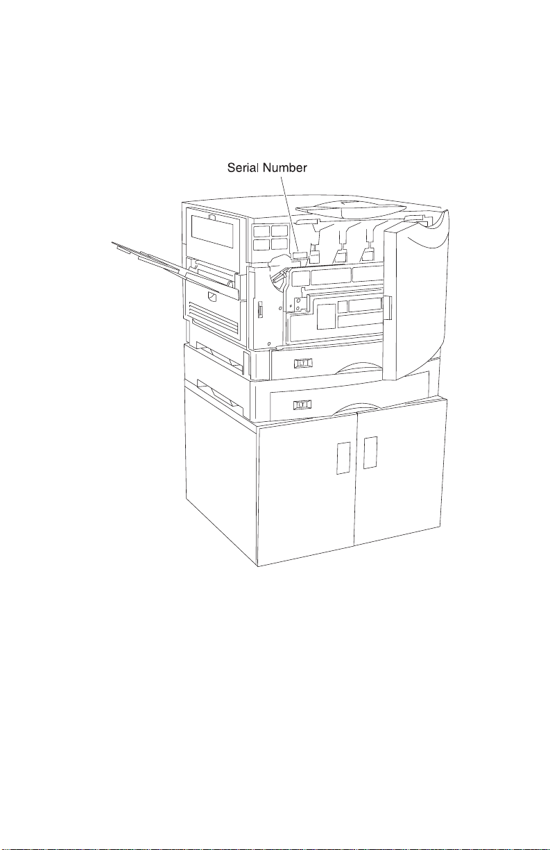
Serial Number
Open the front door, the serial number is located as shown. The
serial number is also on the menu settings page you can print from
the Test s Menu.
General Information 1-3
Page 18

5055-01x
Abbreviations
ASIC Application-Specific Integrated Circuit
CSU Customer Setup
DRAM Dynamic Random Access Memory
EPROM Erasable Programmable Read-Only Memory
EP Electrophotographic Process
ESD Electrostatic Discharge
FRU Field Replaceable Unit
HVPS High Voltage Power Supply
LAN Local Area Net work
LASER Light Amplification by Stimulated Emission of
Radiation
LCD Liquid Cr ys tal Display
LED Light-Emitting Diode
LVPS Low Voltage Power Supply
NVRAM Nonvolatile Random Access Memory
OEM Original Equipment Manufacturer
PICS Problem Isolation Charts
PIXEL Picture Element
POR Power-On Reset
POST Power-On Self Test
PQET Print Quality Enhancement Technology
RIP Raster Image Processor
ROS Read-Only Storage
SRAM S t atic Random Ac cess Memo ry
UPR Used Parts Replacement
V ac Vol ts alternating current
V dc Volts direct current
1-4 Service Manual
Page 19

5055-01x
Processes and Configuration
In this printer, the toner of four colors (magenta, cyan, yellow and
black) melts and deposits on paper, dots which record color image
information. This printing process is called the electrophotography
process.
Electrophotography Process
In the electrophotography process, electrically charged toner,
exposes, develops, transfers, and is cleaned with an aluminum
photosensitive drum. A photoconductive layer forms on the surface
of the drum when the drum is exposed to light.
The surface of the photosensitive drum is negatively charged,
forming the electrostatic image on the surface of the photosensitive
drum. This charge is directed to the photosensitive medium at a low
voltage, reducing the generation of ozone to a very low level. When
the drum surface is charged, the image is recorded by irradiating
light from the LED printhead, forming the electrostatic image. The
LED printhead array along with the Selfoc lens array provide a
single-dot line of the image, in a one-to-one arrangement. The
image data from the printhead controller causes the LED to emit
light in black dots. These black dots form an image of dots on the
photosensitive drum.
The LED printhead minimizes the displacement of images during the
color print process, when images of multiple printheads overlap,
causing dot position accuracy to be much higher. Since light from
the volume of the LED array varies depending on the LED
printheads, the light emitting value is recorded in the EPROM of the
printer controller. When the LED printhead is replaced, the light
emitting value should be entered for each printhead while the printer
is in maintenance mode.
Since the LED printhead and EPROM on the printhead controller
board of this printer are paired, the EPROM on the printhead
controller board should also be replaced whenever the printhead is
replaced.
General Information 1-5
Page 20

5055-01x
Development Unit
Ton er forms the electrostatic image on the photosen sitive drum
during exposure. The single component, non-magnetic toner and the
lusterless color toner are weather-resistant, and fade little under
ultraviolet rays. This is helpful in saving documents.
Toner in the hopper is agitated and supplied to the development roll
by the supply roll. A (conductive rubber) doctor blade is fitted to the
development roll. Toner enters between the development roll and
doctor blade by the rotating dev elopment roll and is negatively
charged, forming the electrostatic image on the photosensitive
drum. Toner attaches to the bright portion of the photosensitive drum
per the voltage of the development roll.
Transfer Unit
Paper feeds electrostatically by the transf er bel t and is carried to the
transfer unit which turn at the speed of the photoconductor drum. A
charge roller applies a positive charge to the paper. The toner image
formed on the photoconductor drum is transferred to the paper from
the back side by the positive dc voltage applied to the transfer sheet,
which is in contact with the paper through the transfer belt.
1-6 Service Manual
Page 21
5055-01x
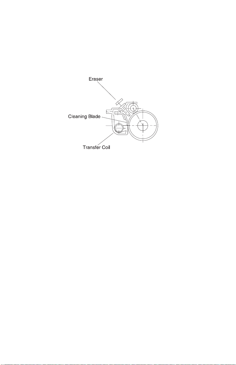
Cleaning Unit
Toner remaining on the photosensitive drum following transfer, is
scraped away with the cleaning blade, and collected in the recovery
bag as waste toner. Residual toner on the photosensitive medium is
removed by the eraser.
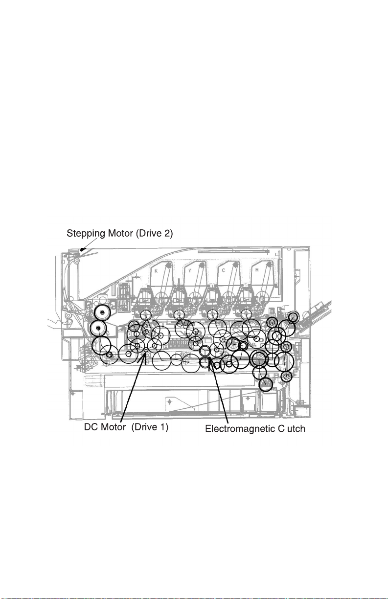
Paper Feeding / Fusing
The main unit drive is composed of drives 1 and 2. Drive 1 feeds
paper, stands by, drives the belt unit, separates, fuses, feeds the
face-up delivery unit, and drives the photodeveloper and toner
cartridge by rotations of the dc motor. Drive 2 drives the face-down
delivery unit by rotations of the stepper motor.
The expansion paper feeder and the duplex unit use independent
motors to drive the paper delivery unit.
General Information 1-7
Page 22
5055-01x
Drive System
Drive 1, composed of a 100 dc motor and gear unit, feeds the
registration paper from the paper feeder and drives the belt unit,
photodeveloper / toner cartridge, fusing unit, and face-up delivery
unit. The motor rotates by the ON signal from the printer controller/
motor drive unit and sends a rotation synchronization detection
signal to the motor drive unit.
Note: The gear unit of drive 1 is adjusted in phase and should not
be disassembled.
Drive 2, composed of a hybrid stepping motor and gear unit, drives
the face-down delivery unit.
1-8 Service Manual
Page 23
5055-01x
Paper Feeding
The paper feeder is a two-way system composed of the multi-paper
feeder (100 sheets maximum) and an integrated 550 sheet tray).
Optionally, the expansion paper feeders (550 sheets) can be
increased to four layers. A high capacity paper feeding system
(3,000 sheets) may be used. Combining the multi-paper feeder,
expansion paper feeders, and high capacity paper feeding system
the printer has a maximum paper supply of up to 5,850 sheets.
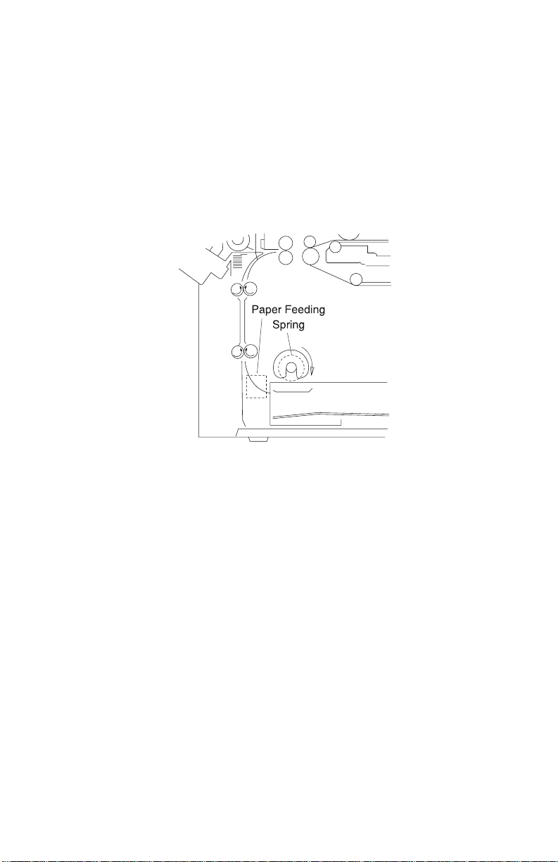
Cassette Paper Feeder
The paper feeding solenoid turns on by the signal from the printer
controller. The paper feeding roller interconnected with drive 1,
rotates with the spring clutch and picks the paper in the paper
cassette.
General Information 1-9
Page 24
5055-01x
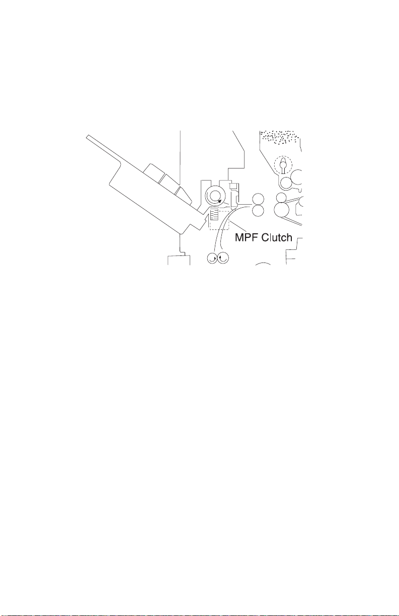
Multi-Purpose Feeding
The multi-paper feed solenoid turns on by the signal from the printer
controller. The multi-purpose feed roll interconnected with the drive 1
through the spring clutch, rotates and picks the paper in the multipurpose feeder.
1-10 Service Manual
Page 25

5055-01x
Registration Unit
Media temporarily stops (registration) when adjusting the paper
leading edge parallel with that of the image, or when adjusting the
timing with the black image.
The upper and lower registration rolls are arranged in parallel with
the photosensitive drum for blac k imaging. The lower registration roll
incorporates a registration clutch which feeds or stops the paper.
In the forward direction of the registration roll, a registration sensor
(photo interrupter) is provided to detect paper fed from the paper
feeder and to stop paper jam feeding.
General Information 1-11
Page 26
5055-01x
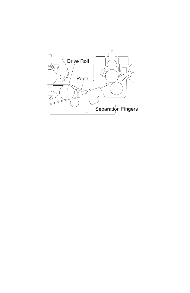
Separation Unit
The transfer belt and paper are separated with the belt drive roll by
separation fingers.
1-12 Service Manual
Page 27
5055-01x
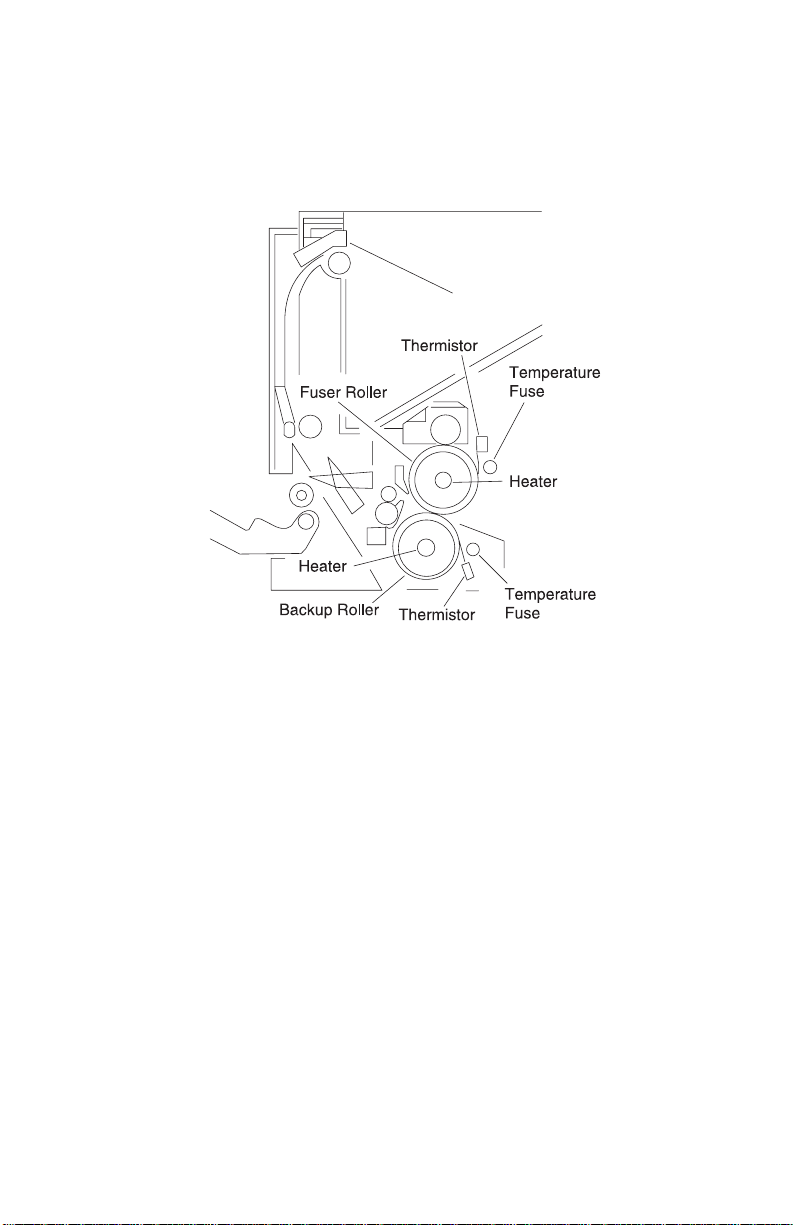
Fuser Unit
By applying heat and pressure, the image is melted and fused to the
paper.
The upper and lower rollers are heated and pressure-fitted. A heater
is positioned in the roller tube and a thermistor and therm ostat
remain in contact with the outside of the tube. Separation fingers are
attached near the upper roller to separate the paper from the roller .
Each thermistor sends the surface temperature of the roller to the
printer controller. The printer controller turns the heater on or off
according to the voltage of each thermistor. If the controller f ai ls and
the temperature of the roller exceeds specifications, the temperature
fuse (TCO) connected to each heater opens, preventing
overheating.
General Information 1-13
Page 28
5055-01x
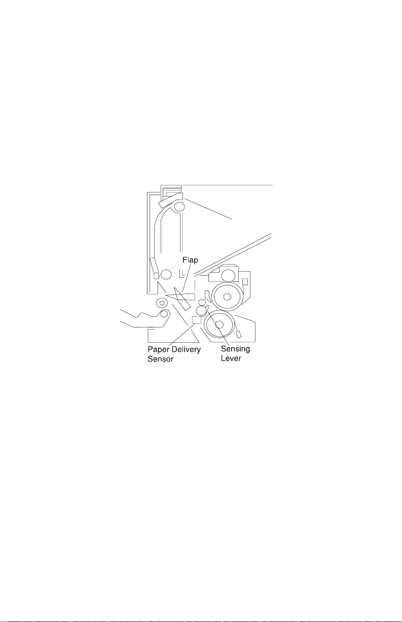
Delivery
After completing the fusing process, paper is discharged from the
printer. The delivery sensor detects the paper condition and the
FU/FD deflector switches between the face-up and face-down paper
delivery. The paper from the fuser pulls down the sensing lever
turning on the delivery sensor (photo interrupter). If the delivery unit
remains on longer than specified, the printer controller determines
that the printer is jammed, and the paper delivery flap lever switches
to either face-down or face-up.
1-14 Service Manual
Page 29

5055-01x
Belt Unit
After passing through the registration unit, paper is electrostatically
fed by the transf er belt through the positively charged feed rol l at the
inlet of the belt unit and fed by the running belt. The belt runs at the
same speed as the photosensitive drum causing the image on the
C, M, Y and K developer to transfer to paper.
Since the photosensitive drum has a small diameter and the paper is
electrostatically fed by the transfer belt, the paper is easily
separated, after toner image transfer, and fed to the next developer.
Excess toner is scraped from the drum with a cleaning blade and
recovered into the waste toner bottle.
Adjust the registration when the belt unit is replaced. The
registration is adjusted at the leading edge of the image or by
adjusting the color image. This should be adjusted in maintenance
mode, when the belt unit is replaced.
The transfer belt is conductive and seamless. If the transfer belt is
damaged, toner can cling to the belt and contaminate the paper.
When fingerprints or other stains appear on the belt, wipe them
away with a dry cloth or cloth moistened with alcohol.
A density sensor is positioned facing the belt drive roller for
automatic density adjustment and registration adjustment. A
mechanism is provided to clean the sensor surface, which is
interconnected with the opening and closing of the front cover.
General Information 1-15
Page 30
5055-01x
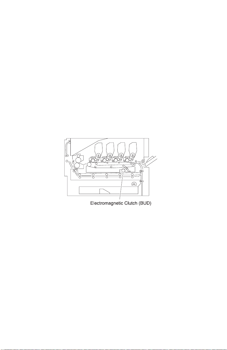
Belt Up/Down
In monochrome printing, switching to color printing is not required.
To avoid unnecessar y wear of the photosensitive drum by the
cleaning blade, this operation is stopped with the electromagnetic
clutch in drive 1. The transfer belt is lowered so as not to touch the
photosensitive drum during color printing.
The transfer belt moves up and down with the switching shaft cam by
the electromagnetic clutch in drive 1. The belt position is used to
detect the cam position with the photo sensor, using the fan shaped
light blocking plate attached to the switching shaft. Printing with the
transfer belt lowered is called monochrome mode and color printing
is called color mode.
Expansion Paper Fee der
The optional expansion paper feeder can be installed at the lower
part of the main unit. Including the main unit, up to five layers of
cassettes can be used for cassette paper feeding.
1-16 Service Manual
Page 31

5055-01x
Duplex Unit
A duplex unit can be optionally installed in the main unit, allowing
two-sided printing.
Selecting Paper feeding, Registration, Transfer, Separation,
Fusing, or Face-Down pa per di s cha rgi ng w ith the pulse motor in
the duplex unit, feeding is stopped before the paper is delivered.
Paper delivery is then reversed and fed to the duplex unit.
Paper fed with the duplex unit stops once, and the center position is
corrected by the operation of the side guide plate. Paper is then refed by the printer controller signal to the main unit, and, following
printing on the back side, is delivered to the normal feeding path.
General Information 1-17
Page 32

5055-01x
Printi ng Mod e
Usually printing is performed in normal mode, OHP mode, thick
paper mode, and envelope/postcard mode. The mode is switched by
a command from the interface controller.
Mode Paper/Media Weight PPM (Color)
Normal 16 - 29 lb 28
Thick paper 32 lb (glossy) 22
Enve lope/postcard 90 lb or more 10
OHP Transparency 6
OHP Mode
OHP mode is used for improving color printing on transparencies.
With an overhead projector (OHP), light transmitted through OHP
paper (original document) projects an image on the lens. If the
smoothness of the surface of the toner image on the OHP paper is
too low, transmission is prevented due to the diffused reflection.
Images projected in color printing appear in monochrome.
When non-offset type color toner is used, the process speed in the
OHP mode is decreased, causing toner to melt sufficiently with the
fusing unit, while the fusing temperature is set higher than usual to
increase the smoothness on the surface of the toner image.
This mode restricts paper feeding to multi-paper feeding, not
cassette feeding.
Thick Paper Mode
Thick paper mode is used to improve print quality on thick paper.
(More than 105 g/m
1-18 Service Manual
2
(90kg)).
Page 33

5055-01x
Envelope / Postcard Mode
Envelope / postcard mode is used to improve printing quality on thick
paper of small width. In this mode, the fusing temperature is set
higher than usual and transfer voltage is switched according to the
temperature.
Operation Mode
Operation modes such as sleep mode and registration mode are
switched by command from the interface controller.
By carefully selecting print media and loading them properly, you
can avoid most paper jams. If jams do occur, follow the steps
outlined in this section.
To resolve the paper jam messages, you must clear the jammed
area and then press Go to clear the message and resume printing.
The printer prints a new copy of the page that jammed if Jam
Recovery is set to On or Auto; however, the Auto setting does not
guarantee the page will print.
General Information 1-19
Page 34

5055-01x
Clearing Paper Jams
200 Paper Jam <x> Pages Jammed (Check Areas A-F)
A 200 Paper Jam message indicates that paper is jammed. The
display alternates between 200 Paper Jam <x> Pages Jammed and
Check Areas A-F.
If there is a paper jam when you turn the printer on, the second line
of the 200 Paper Jam message will be blank. To res olve the
message, you must clear all paper from the paper path. Check and
clear areas A through F.
Check Areas A,B
This message indicates a paper jam in the transfer belt, fuser, or
output roller area. To clear areas A–B:
1. Open the top cover. Never touch the photodeveloper drum on
the underside of the toner cartridge. The paper may be covered
with un-fused toner, which can stain clothing.
2. Remove any paper on the transfer belt.
3. If the paper source was the multipurpose feeder, check the area
between the multipurpose feeder and the transfer belt. Do not
use any pointed objects to remove the paper. This could cause
permanent damage to the transfer belt.
4. Check the fuser area and top cover for additional jams.
5. If there is no jam in the fuser area or top cover, close the top
cover and front door, and then press Go. If a jam is present,
continue with step 4.
6. Lift the fuser pressure release lever and slowly pull the paper
out of the fuser toward the inside of the printer.
7. Rotate the fuser pressure release lever down.The top cover will
not close until the lever is in the down position.
8. Check the top cover for additional jams.
9. If there is no jam in the top cover, close the top cover and front
door, and then press Go.
10. Remove the jam from the top cover.
11. Close the top cover and the front door.
1-20 Service Manual
Page 35

5055-01x
Check Area C
Jams that cause a Check Area C message require opening the
duplex jam access door. If you are printing on small paper, the
following steps may not clear the jam. See “Removing Small Size
Pape r From the Dupl ex Uni t” on page 1-22.
1. Open the duplex jam access door on the right side of the printer.
2. Remove the jam.
3. Press Go.
Note: If the paper jam message continues, check and clear all
paper from the paper path.
Check Area D
This message indicates a paper jam in the duplex unit area. To clear
area D:
1. Open the duplex jam access door on the right side of the printer.
2. Gently pull out the duplex unit.
3. Tur n the paper forwarding dial counterclockwise. If the paper
advances out of the duplex unit, remove the jam and go to step
7. If the paper does not advance, go to step 4.
4. Open the duplex unit covers.
5. Remove the jam.
6. Close the duplex unit covers.
7. Push the duplex unit back into the printer.
8. Close the access door.
9. Press Go. If the paper jam message continues, check and clear
all paper from the paper path.
General Information 1-21
Page 36

5055-01x
Removing Small Size Paper From the Duplex Unit
When printing on both sides of A5 or other small size paper, you
may need to partially remove the duplex unit to clear the jam.
1. Turn off the printer.
2. Open the duplex unit door.
3. Loosen t he tw o screws.
4. Pull out the duplex unit far enough to see the duplex unit inlet.
5. Remove jam from the duplex unit inlet.
6. Slide the duplex unit in.
7. Align the thumbscrews on the duplex unit with the holes in the
printer.
8. Tighten the thumbscrews to secure the duplex unit.
9. Close the duplex unit door.
Check Area E
This message indicates a jam in the top, middle, or bottom optional
drawer paper path area. If you have a high capacity feeder, pull the
feeder away from the printer.
1. Open the jam access door on the top optional drawer.
2. Remove the jam.
3. Close the jam access door.
4. Open the jam access door on the middle optional drawer.
5. Remove the jam.
6. Close the jam access door.
7. Open the jam access door on the bottom optional drawer.
8. Remove the jam.
9. Close the jam access door.
10. Press Go.
Note: If the paper jam message continues, check and clear all
paper from the paper path.
1-22 Service Manual
Page 37

5055-01x
Check Area F
1. Pull the high capacity feeder away from the printer.
2. Open the jam access door on the top optional drawer.
3. Remove any jams.
4. Close the jam access door.
5. Slide the high capacity feeder until the feeder locks to the
docking frame. When the feeder is in the correct position, you
hear a click.
6. Press Go.
Note: If the paper jam message continues, check and clear all
paper from the paper path.
240 Paper Jam Check MP Feeder
1. Slowly pull the jam straight out of the multipurpose feeder. If the
paper will not come out, continue.
2. Open the top cover.
3. Remove the paper on the transfer belt.
4. Close the top cover.
5. Press Go.
24<x> Paper Jam Check Tray <x>
Jams in five areas result in a 24<x> Paper Jam message, where x
represents the tray number where the jam has occurred. Paper jam
messages 241–244 indicate a jam has occurred in one of the trays.
241-244 Paper Jam
1. Pull out the tray indicated on the display.
2. Remove any wrinkled or creased paper.
3. Push down on the remaining paper in the tray until the bottom
plate clicks into place.
4. Close the tray.
5. Press Go.
Note: If the paper jam message continues, check and clear all
paper from the paper path.
General Information 1-23
Page 38

5055-01x
249 Paper Jam Check Tray <x>
A 249 Paper Jam Check T ray <x> message indicates a jam has
occurred in the high capacity feeder.
1. Open the top cover.
2. Remove the jam.
3. Close the top cover.
4. Press Go.
1-24 Service Manual
Page 39

5055-01x
High Capacity Paper Feeder (HCPF)
Paper Feed and Separation Mechanism
The high capacity paper feeder consists of a tray and paper transfer .
The paper feed and separation mechanism uses a friction roller
separation and paper feed system with a non-contact magnet type
maintenance-free torque limiter.
When the paper feed clutch turns on, the paper feed roller shaft
rotates and the paper feed roller is driven with the one-way clutch.
The call roller rotates with the relay gears to feed the top paper. The
reverse roller rotates along with the paper feed roller.
During paper feed, if two sheets feed, the reverse roller rotates by
the torque limiter, returning the lower sheet. When the paper feed
sensor (reflection type sensor) detects the paper, the pickup
solenoid turns off to raise the call roller, transferring the paper to the
registration roller.
General Information 1-25
Page 40

5055-01x
Registration Operation
When the paper feed motor rotates, the transfer roller is driven with
relay gears. The reverse roller shaft rotates the gears on the paper
feed clutch in the direction of the arrow and stops b y the friction forc e
of the paper feed roller.
1-26 Service Manual
Page 41

5055-01x
Tray Up/Down Mechanism
The driving force of the tray motor transmits to the tray driving pulley
through the gears. Moving the tray moves up and down through the
tray driving belt. After the paper loads, and the top cover is set, the
pickup solenoid turns on to lower the call roller. When the tra y moves
up, the call roller is raised by the top surface of the paper, and the
shield plate on the up sensor is released from the up sensor which
turns off the tray motor.
Also, when the top surface of the paper lowers during printing and
the up sensor is shielded, the tray motor again rotates forward to
raise the paper.
General Information 1-27
Page 42

5055-01x
When the down button is pressed, the tray motor reverses to move
the tray down. During the down motion of the tray, as the top surface
of paper passes the paper level sensor, the tray motor stops. The
tray moves down by about 500 sheets. The down sensor detects the
tray lower limit position.
1-28 Service Manual
Page 43

5055-01x
Tray Up Condition
Tray up motion stops when the:
• Up sensor is OFF (not shielded)
• Power cord is connected and the joint SW is ON
• Up sensor is ON (shielded) during printing
• Top cover is closed, or when up sensor is ON
Tray Down Condition
Tray down motion stops when the:
• Paper level sensor is OFF
• Down button is pressed
• Paper end is detected
General Information 1-29
Page 44

5055-01x
Size Detection Mechanism
The paper size can be switched between A4 and letter (11 inches)
by changing the side fence position.
The paper size sensor 2 detects the fixing screw 2 at the A4
position.
The paper size sensor 1 detects the fixing screw 1 at the letter
position. Tray up motion stops when the up sensor is OFF, not
shielded.
1-30 Service Manual
Page 45

5055-01x
Residual Paper Detection Mechanism
The residual paper quantity in the tray is detected with four photo
interrupters. The quantity of pages remaining in the sheet feeder,
displays in the following increments:
• Near end, about 80 sheets
• About 300 sheets
• About 1,000 sheets
• About 2,000 sheets
General Information 1-31
Page 46

5055-01x
Paper End Detection
A reflection type sensor is provided on the top stay to detect the
paper top surface and the paper end.
1-32 Service Manual
Page 47

5055-01x
Maintenance Mode
DIP Switch Specifications
The DIP switches on the high capacity paper feed board have the
following functions:
• Function switching and initial setting of t he standard machine or
optional machine.
Function Switch Maintenance Switch
DIP
Switch
43 2 1
Description
OFF 1 Standard machi ne
ON XX
OFF X 2 Optional machine
ON X
initial s et ti ng
initial s et ti ng
• Maintenance switch (test mode selection) is valid without
connecting to the printer controller board.
Function Switch Maintenance Switch
DIP
Switch
43 2 1
OFF Test OFF mode
ON XX
OFF X Linear velocity 101
ON X
OFF XXLinear velocity 129
ON
T est paper feed
mode
(stand alone)
mm/s
Thick paper mode
mm/s
Plain paper mode
OFF X Linear velocity 180
ON X
mm/s
General Information 1-33
Page 48

5055-01x
• Test pap er feed operation.
1. Turn on the docking safety switch with a non-metallic object.
The interface cable with the printer controller board need not be
connected.
2. Close the top cover or manually activate the cover switch.
3. Load paper.
4. Wait until the paper tray stops and the pickup solenoid turns off
5. With the cover closed or with the cover switch activated, press
and hold the tray down button for more than 1/2 second. In
steps 1 and 2, paper feeding starts and is continuously fed until
the cover is opened. The test ends when the tray motor stops
and the paper ejects or the tray down button is released.
• Test Sequence
1. The tray motor moves the tray to the upper limit.
2. The pickup solenoid activates then de-activates.
3. When the tray down switch is pressed for longer than 1/2
second, the paper feed motor starts, the paper feed clutch
operates and feeding begins.
4. Feeding can be stopped by releasing the tray down button.
1-34 Service Manual
Page 49

5055-01x
High Capacity Paper Feed Sensor / Switch Test
The condition of each sensor can be checked from the lighting of
LEDs on the high capacity paper feed board. When each sensor
operates with the power supplied, the associated LED lights.
To perform the test:
Interrupt the photointerrupter sensor signal or actuate the micro-
switch being tested while observing the associated LED on the high
capacity paper feed board.
LED Sensor Name
1 Paper size sensor 1 switch (letter size 11 inches)
2 Paper size sensor 1 switch (A4 size)
3 Residual paper sensor 1 switch
4 Residual paper sensor 2 switch
5 Residual paper sensor 3 switch
6 Residual paper sensor 4 switch
7 Paper le vel sensor switch
8 Lower limit switch
9 Cover open sensor switch
10 Docking sensor switch
11 Upper limit switch
12 Paper sens or switch
13 Paper feed sensor switch
General Information 1-35
Page 50

5055-01x
1-36 Service Manual
Page 51

5055-01x
2. Diagnostic Information
The diagnostic information in this chapter leads you to the failing
part. Before you replace an entire assembly, determine if just the
defective part is available in the parts catalog. Use the error code
tables, symptom table, service checks and the diagnostic aids
chapter to determine the symptom and repair the failure. The
removal procedures in the Repair Information chapter may help you
identify parts. After you complete the repair, perform the appropriate
tests to ver i fy the rep a i r.
If an error is displayed, locate it in the “Service Error Message
Table” on pag e 2-4, the “Attendance Messages g” on page 2-25,
or the “Symptom Table” on page2-52 and take the appropriate
action.
If an error message appears while you are working on the printer, go
to the error message table and take the indicated action.
Adjustments and Procedures Following Parts
Replacement
Note: When trouble shooting, or prior to making any adjustment to
print quality, always be sure:
• The printer is installed on a level rigid surface.
• The photodevelopers are never exchanged. Do not exchange a
black photodeveloper for a color photodeveloper, as they have
different surface phase counts.
• The Alignment Page is used when adjusting print registration.
Whenever you replace any of the following parts be sure to perform
the required adjustments or procedures. The adjustments are in the
Repair Information and Diagnostic Aids chapters.
Diagnostic Information 2-1
Page 52

5055-01x
Printer Controller Board/Prin ter Contr ol EPROM (U5)
If you replace the printer controller board, remove EPROM (U5) and
install it on the new board. Also check the printhead alignment.
If you change the EPROM, the following items must be checked and
adjusted in the diagnostic mode.
• LED Printhead Light Quantity
• Printer Alignment (X, Y, and Theta)
• Counters
• Configuration ID
RIP Controller Board
If you replace the RIP controller board be sure to move the solid
state drive, memory, and option cards from the old card to the new
one.
Transfer Belt
If you replace the transfer belt, check the printer alignment (X, Y, and
Theta), adjusted in diagnostic mode.
LED Printhead Controller Board or LED Printhead
If you replace the LED printhead controller board or LED printhead,
the following items must be checked and adjusted in diagnostic
mode:
• LED printhead light quantity
• Printer alignment (X, Y, and Theta)
2-2 Service Manual
Page 53

5055-01x
Start
Initial Check
Before you start troubleshooting, check the following:
Installation Environment
• The power supply line voltage is plus or minus 10% of the rated
line voltage.
• The machine is securely installed on a level surface in a well-
ventilated place.
• The room temperature is between 10 and 32°C (50 and 90°F)
and the relative humidity between 20 and 80%.
• Avoid sites generating ammonia gas, high temperature, high
humidity (near water faucets, kettles, humidifiers), cold spaces,
near open flames, and dusty areas.
• A void sites exposed to direct sunlight.
Print Paper Checks
• Be sure to use the recommended paper for this printer.
• Check the paper for dampness. Make a trial print with paper
from a newly opened package, and check the result.
Diagnostic Information 2-3
Page 54

5055-01x
Printer Messages
The printer displays three types of messages: service messages,
status messages, and attendance messages. Service messages
indicate a problem that requires a service technician. Status
messages provide information about the current state of the printer,
requiring no action. Attendance messages alert the operator to
printer problems that require operator intervention.
Service Error Message Table
900 - Unrecoverable Software Error (Operator Manual)
910 Ser v ice
Motor Error
910 - Drive Motor Error
Step
1
2
3
4
5
Question s /
Actions
Are connectors CN1
and CN5 on the motor
drive board connected
properly?
Is connector CN33 on
the printer controller
board connected
properly?
Is there an abnormal
load on the toner or
drum unit?
Did replacement of the
printer controller board
solve the problem?
Did replacement of the
motor drive board
solve the problem?
Yes No
Go to step 2. Connect CN1
and CN5.
Go to step 3. Connect CN33.
Replace the
toner or drum
unit.
Problem
solved.
Problem
solved.
Replace the
printer controller
board and go to
step 4.
Replace the
motor drive
board and go to
step 5.
Replace the
drive motor.
2-4 Service Manual
Page 55

5055-01x
911 - Paper Exit Motor Error
Step
1
2
Questions /
Actions
Is connector CN4 on
the printer controller
board securely
connected?
Did replacement of the
paper exit motor solve
the problem?
Yes No
Replace the
paper exit
motor and go to
step 2.
Problem solved. Replace the
Plug the
connector in
securely.
printer controller
board.
912 - High Capacity Paper Feed Motor Error
Step
1
Questions /
Actions
Is connector CN40 on
the printer controller
board securely
connected?
Yes No
Go to “High
Capacity Paper
Feed (HCPF)
Service
Check” on
page 2-57.
Plug the
connector in
securely.
Diagnostic Information 2-5
Page 56

5055-01x
917 - RIP Fan Error
917 Ser v ice
Fan Error
Step Questions / Actions Yes No
Is connector J5 on the
1
RIP board connected
properly?
2 Is 24 V dc present
between pins 1 and 3 of
connector J5 on the RIP
board?
Go to step 2.
Replace the RIP
fan.
Properly
connect J5.
Replace the
RIP board.
918 - Main Unit Fan Error
Step Questions / Actions Yes No
1 Is +24 V present betwe en
pins 1 and 3 on
connectors CN17 (upper
left fan) and CN5 (upper
right fan) on the printer
controller board?
Replace the failing
fan.
Replace the
printer
controller
board.
919 - Power Supply Fan Error
Step Questions / Actions Yes No
1 Is +24 V present betwe en
pins 1 and 3 of connector
CN6 on the printer
controller board?
2-6 Service Manual
Replace the power
supply fan.
Replace the
printer
controller
board.
Page 57

5055-01x
920 - Fuser Error - Fuser Heater Trouble
92x Service
Fuser E rror
Step
1 Replace the fuser.
2 Did replacing
Questions /
Actions
Did thi s fix the
problem?
power supply 2 fix
the problem?
Yes No
Problem solved. Return the fuser,
replace the power
supply 2 and go to
step 2.
Problem solved. Return power supply
2 and replace the
printer controller
board.
923 - Upper Fuser Thermistor Open Error
Step
1 Is connector CN44
2 Is error 923
Questions /
Actions
on the printer
controller board
connected
properly?
displayed?
Yes No
Disconnect CN44
and turn the printer
on.
Go to step 2.
Power off and
reconnect CN44.
Go to step 3.
Plug the connect or in
securely.
Replace the printer
controlle r board.
3 Power the printer
off and short pins
1 and 4 of CN44
and power on. Is
error 923
displayed?
Replace the fuser. Replace the printer
controlle r board.
Diagnostic Information 2-7
Page 58

5055-01x
924 - Lower Fuser Thermistor Open Error
Step
1 Is connect or CN44
2 Is error 924
3 Power the printer
Questions /
Actions
on the printer
controller board
connected
properly?
displayed?
off and short pins
8 and 11 of CN44
and turn the
printer on.
Is error 924
displayed?
Yes No
Disconnect CN44
and turn the printer
on.
Go to step 2.
Turn the printer off
and reconnect
CN44.
Go to step 3.
Replace the fuser. Replace the printer
925 - High Pressure Controller Error
Step
Questions /
Actions
Yes No
Plug the connector i n
securely.
Replace the printer
controller board.
controller board.
1 Is connect or CN42
on the printer
controller board
connected
properly?
2 Did replacing the
printer controller
board fix the
problem?
2-8 Service Manual
Replace the printer
controller board.
Go to step 2.
Problem solved. Replace the high
Plug the connector i n
securely.
voltage power board
(HVU).
Page 59

5055-01x
926(K), 927(C), 928(Y), 929(M) - Toner Sensor Error
92x Service
Toner Sensor
Step
1 Is the ton er c artridg e
2 Is the ton er c artridg e
3 Replace the toner
4 Test the sensors.
Questions /
Actions
the cor re c t ty p e for
the printer?
encoder wheel dirty?
cartridge for the
color with the error.
Did this fix th e
problem?
While actuatin g the
sensor, does the
voltage fluctuate
between
0 V and +5 V
between pins 1 and
2 on connectors
CN22(K), CN21(Y),
CN18(M), and
CN19(C) on the
printer controller
board?
Yes No
Go to step 2. Recommend the
customer replace
the cartridge with
the correct type.
Clean the encoder
wheel and toner
sensor.
Problem solved. Go to step 4.
Replace the printer
controller board.
Go to step 3.
Replace the
affected toner
sensor.
Diagnostic Information 2-9
Page 60

5055-01x
930 - Yellow Printhead Error
930 Ser v ice
Printhead Error
Step
1 Is fuse 5 on the
Questions /
Actions
printhead control
board open?
Replace the
printhead control
board, cables, and
LED printhead.
931 - Magenta Printhead Error
Step
1 Is fuse 6 on the
Questions /
Actions
printhead control
board open?
Replace the
printhead control
board, cables, and
LED printhead.
932 - Cyan Printhead Error
Step
Questions /
Actions
Yes No
Replace the
printhead
controller board.
Yes No
Replace the
printhead controll er
board.
Yes No
1 Is fuse 3 on the
printhead control
board open?
2-10 Service Manual
Replace the
printhead control
board, cables, and
LED printhead.
Replace the
printhead controll er
board.
Page 61

5055-01x
933 - Black Printhead Error
Step
1 Is fuse 4 on the
Questions /
Actions
printhead control
board open?
Replace the
printhead control
board, cables , and
LED printhead.
934 - Color Drum Sensor Error
934 Servic e
Drum Sensor
Step
1 Is connector CN28
2 Clean the color drum
3 Did replacing the
Question s /
Actions
Go to step 2. Plug the connector
connected properly?
Problem solved. Replace the color
sensor LED. Did this
fix the prob lem?
Problem solved. Replace the
color drum sensor f ix
the problem?
Yes No
Replace the
printhead
controller board.
Yes No
in securely.
drum sensor.
Go to step 3.
printer controller
board.
Diagnostic Information 2-11
Page 62

5055-01x
935 - Black Drum Sensor Error
Step
1 Is connector CN27
2 Clean the black
3 Did replacing the
Questions /
Actions
connected properl y?
drum sensor LED.
Did thi s fix the
problem?
black drum sensor
fix the problem?
936 - 939 Cassette Error
936 Ser v ice
Paper Option
Step
1 Are connectors
Questions /
Actions
CN35 and CN36
on the printer
controller board
connected
properly?
Yes No
Go to step 2. Plug the connector
in securely.
Problem solved. Replace the black
drum sensor.
Go to step 3.
Problem solved. Replace the printer
controller board.
Yes No
Replace the printer
controller board.
Plug the connector i n
securely.
2-12 Service Manual
Page 63

5055-01x
940 - High Capacity Paper Feed Sensor Error
Step
1 Is connector CN40
Questions /
Actions
on the printer
controller board
connected properly?
Yes No
Go to “High
Capacity Paper
Feed (HCPF)
Service Check” on
page 2-57.
941 - High Capacity Paper Feed Tray Error
Step
1
Questions /
Actions
Is connector CN40
on the printer
controller board
connected properly?
Yes No
Go to “High
Capacity Paper
Feed (HCPF)
Service Check”
on page 2-57.
942 - Duplex Error
942 Servic e
Duplex
Plug the con nector
in secure ly.
Plug the con nector
in secure ly.
Step
1 Is connector CN37
Questions /
Actions
on the printer
controller board
connected properly ?
Yes No
Replace the printer
controller board.
Diagnostic Information 2-13
Plug the connect or
in securely.
Page 64

5055-01x
945 - Engine Flash Error
945 Ser v ice
Engine Flash
Reflash the engine code.
946 - Printer / Printhead Controller Board
Communication Error
946 Ser v ice
Communication
Step
1
Questions /
Actions
Replace the
printhead controller
board. Did this f ix the
problem?
Yes No
Problem solved. Repla ce the
printer controller
board.
2-14 Service Manual
Page 65

5055-01x
948 - Machine ID Error
948 Servic e
Machine ID
Step
1 Turn the printer off
2 Are the EPROMs
3 Did replacing the
Question s /
Actions
and wai t 30 second s.
Turn the printer on.
Did this fix the
problem?
installed correctly?
printer controller
board fix the
problem?
952 - NVRAM Chip Failure
952 Servic e
NVRAM Failure
Yes No
Problem solved. Verify proper
installat ion of th e
EPROMs on both
the printer
controller board
and the printhead
controller board.
Go to step 2.
Replace the printer
controller board.
Go to step 3.
Problem solved. Replace the
Install the
EPROMs
correctly.
printhead
controller board.
Replace the printer controller board.
954 - NVRAM CRC Failure
Replace the RIP board.
955 - Code CRC
955 Servic e
Code CRC <loc>
Replace the RIP board.
Diagnostic Information 2-15
Page 66

5055-01x
956 - Processor Failure
956 Ser v ice
System Board
Replace the RIP board.
957 - ASIC Failure
Replace the RIP board.
958 - NAND Failure
958 Ser v ice
NAND Failure
Replace the RIP board.
960 - RAM Slot 1 Bad
960 Ser v ice
RAM Memory Error
Replace RAM Card or the RIP board.
961 - RAM Slot 2 Bad
Replace RAM Card or the RIP board.
962 - RAM Slot 3 Bad
Replace RAM Card or the RIP board.
964 - Emulation Error
964 Ser v ice
Emulation Error
Replace the DLE board. If this does not fix the problem, replace the
RIP board.
2-16 Service Manual
Page 67

5055-01x
970 - Standard Network Error
970 Servic e
Standard Network
970 Servic e
Network Card X
975 - Unrecognizable Network Port
Software error.
976 - Unrecoverable Software Error in Network Port
Software error. To to the “Options Service Check” on page 2-77
and refer to the network card option section.
978 - Bad Check sum While Pr ogra mming Networ k Card
Software error.
979 - Flash Parts Failed While Programming Network
Port
Reflash network port.
Diagnostic Information 2-17
Page 68

5055-01x
980 - Face-Up/Down Switching Error
980 Ser v ice
Switch Error
Chec k Area
B
Step
1 Is the linkage
2 Is there continuity
3 Test the sensor.
Questions /
Actions
between the
FU/FD de f le c to r
and the FU
deflector solenoid
operating
properly?
on the FU
deflector solenoid
between pins 1
and 2 of CN14 on
the printer
controller board?
While actuating
the sensor, does
the voltag e
fluctuate between
0V and +5 V
between pins 1
and 2 on
connector CN12
on the printer
controller board?
Yes No
Go to step 2. Replace the face-up
exit assembly.
Go to step 3. Replace the FU
deflector solenoid.
Replace the printer
controller board.
Replace the FU/FD
deflector sens or.
2-18 Service Manual
Page 69

5055-01x
981 - Belt Up/Down Sensor Error
981 Servic e
Switch Error
Step
1 Are connectors
2 Are connectors
3 Verify the belt up/
Questions /
Actions
CN409 and
CN407 on the
sensor board
connected
properly?
CN26 and CN29
on the printer
controller board
connected
properly?
down sensor
actuator is
properly blocking
the sensor by
manually
operating the belt
up/down shaft.
Is it properly
blocking the
sensor?
Yes No
Go to step 2. Plug the connectors
in securely.
Go to step 3. Plug the connector i n
securely.
Go to step 4. Replace the sensor
or actuator as
necessary.
4 Clean the belt up/
down sensor.
Does this fix the
problem?
Problem solved. Go to step 5.
Diagnostic Information 2-19
Page 70

5055-01x
Step
5 Test the sensor.
6 Did replacing the
Questions /
Actions
While actuating
the sensor, does
the voltag e
fluctuate between
0V and +5 V
between pins 8
and 10 of
connector CN29
on the printer
controller board?
belt up/down
clutch fix the
problem?
Replace the belt up/
down clutch.
Go to step 6.
Problem solved. Replace the printer
982 - Sensor Controller Error
982 Ser v ice
Sensor C ont rol
Yes No
Replace the belt up/
down sensor.
controller board.
Step
1
Questions /
Actions
Turn the printer off
and wait 30 seconds .
Turn the printer on.
Is error 982
displayed?
2-20 Service Manual
Yes No
Replace the
printer controller
board.
Problem so lved.
Page 71

5055-01x
983 - Black Gear Sensor Error
983 Servic e
Gear Sensor
Step
1 Is connector CN20
2 Clean the gear
Question s /
Actions
Go to step 2. Plug the connector
on the printer
controller board
connected properly?
Problem solved. Replace the K
sensor. Does this fix
the problem?
984 - Yellow Gear Sensor Error
Step
1 Is connector CN20
2 Clean the gear
Questions /
Actions
Go to step 2. Plug the connector
on the printer
controller board
connected properly ?
Problem solved. Replace the Y
sensor. Does this fix
the problem?
Yes No
in securely.
drive unit gear
sensor. If the
problem remains,
replace the printer
controller board.
Yes No
in securely.
drive unit gear
sensor. If the
problem remains,
replace the printer
controller board.
Diagnostic Information 2-21
Page 72

5055-01x
985 - Transfer Belt Thermistor Error
985 Ser v ice
Thermistor Error
Step
1 Are connectors
2 Is connector CN29
Questions /
Actions
CN407 and CN408
on the sensor board
connected properly?
on the printer
controller board
connected properly?
Yes No
Go to step 2. Plug the connector
Replace the transf er
belt unit. If the
problem rema ins,
replace the printer
controller board.
986 - Transparency (OHP) Sensor Error
986 Ser v ice
OHP Sens or
Step
1 Are connectors
Questions /
Actions
CN15 (light emit ti ng)
and CN7 (light
receiving) on the
printer controller
board connected
properly?
Yes No
Go to step 2. Plug the connector
in securely.
Plug the connector
in securely.
in securely.
2-22 Service Manual
Page 73

5055-01x
Step
2 Test the sensor.
Question s /
Actions
While actuating the
sensor, does the
voltage fluctuate
between 0V and +5
between pins 2 and
3 of connector CN7
of the printer
controller board?
Yes No
Replace the printer
controller board.
992 - Temperature/Humidity Sensor Error
Step
1 Is connector CN3 on
2 Replace the
Question s /
Actions
the printer controller
board connected
properly?
temperature and
humidity sens or. Did
this fix the pro blem?
Yes No
Go to step 2. Plug the connector
Problem solved. Replace the
Replace the upper
and lower
transparency
sensor.
in securely.
printer controller
board.
993 CPU Error
Replace the printer controller board.
Diagnostic Information 2-23
Page 74

5055-01x
994 - Density Sensor Error
Step
1 Are connectors
2 Is connect or CN29
3 Did replacing the
Questions /
Actions
CN406 and
CN407 on the
sensor board
connected
properly?
on the printer
controller board
connected
properly?
density sensor fix
the problem?
Yes No
Go to step 2. Plug the connector in
securely.
Replace the density
sensor.
Go to step 3.
Problem solved. Replace the printer
Plug the connector i n
securely.
controller board.
2-24 Service Manual
Page 75

5055-01x
Attendance Messages g
Message Meaning Action
Activating Menu
Changes
Bin <x> Full The specified bin is full. Remove the paper from
Busy The printer is busy receiving,
Canceling Fax The printer is processing a
Canceling Job The printer is processing a
Change <x> The printer is requesting a
Check <de vice>
connection
The pri nte r is activating
changes made to the printer
settings.
processing or printing data.
request to cancel a fax job.
request to cancel the current
print jo b.
different type of paper.
• The specified devic e is not
fully connect ed.
• Hardware failure .
Wait for the message to
clear.
the bin.
Wait for the message to
clear or press Menu to
open the Job Menu and
cancel the current job.
Wait for the message to
clear.
Wait for the message to
clear.
Change paper.
• Reestablish
communication by
reattaching the device.
• Press Go to clear the
message.
• If a hardware failur e,
turn the printer off and
back o n . If the error
recurs, turn the printer
off, remo ve the specif ied
device and call for
ser vice. If t he error
cannot be reset,
go to “Map 10 -
Unrecoverable “Check
Tray (X) or Duplex
Connection”
Message” on
page 2-49.
Clearing Job
Accounting Stat
The printer is deleting all job
statistics stored on the hard
disk.
Wait for the message to
clear.
Diagnostic Information 2-25
Page 76

5055-01x
Message Meaning Action
Close Side
Door
Close Top Door The printer top door is open. Close th e printer top door
Close Tray <x>
Top Cover
Copying The printer is processing a
Defragmenting The printer is defrag me nti ng
The printer side door is open . Close the pri nter si de door.
If the error cannot be reset,
go to “Map 1 - False “Side
Door Open” Message”
on page 2-43.
and front door. If the error
cannot be reset go to
“Map 2 - False “Close
T op Door” Message” on
page 2-43.
The high capacit y f eed er door
is open.
copy job originating from the
OptraImage
the flash memory to reclaim
storage space occupied by
deleted resources.
TM
scanner.
Close the HCPF door and
the top cover. If the error
cannot be reset, go to
“Map 3 - False “Close
T ray (X) Top Cover”
Message” on page 2-44.
Wait for the message to
clear.
Wait for the message to
clear.
Warning: Do not turn the
printer off while this
message is displayed.
Delete All Jobs The printer is requesting
confirmation to delete all held
jobs.
Deleting Jobs The printer is deleting one or
more held jobs.
Disabling
Menus
The printer is responding to a
request to disab le the menus.
2-26 Service Manual
• Pr ess Go to continue.
The printer deletes all
held jobs.
• Pr ess Stop to cancel the
operation.
Wait for the message to
clear.
Wait for the message to
clear.
Note: While the menus are
disabled, you cannot
change the print er settings
from the operato r panel .
Page 77

5055-01x
Message Meaning Action
Disk Corrupted
Reformat?
Disk Recovery
x/5 yyy%
Enabling Menus The printer is responding to a
Engine
Warming
Enter PIN:
=______
Fax <x> The pr inter is proce ssing an
Flushing Buffer The printer is flushing
The printer has attempted a
disk recovery process and
cannot repair the disk.
The printer is attempting to
recove r the hard disk.
request to make the menus
available to all users.
The printer is warming the
fuser assembly.
The printer is waiting for you
to enter your four-digit PIN
number.
incoming fax.
corrupted print data and
discarding the current print
job.
• Press Go to reformat the
disk and delete all files
currently stored on the
disk.
• Press Stop to clear the
message without
reformatting the disk.
Wait for the message to
clear.
Warning: Do not turn th e
printe r of f w h ile this
message is displayed.
Wait for the message to
clear and press Menu to
view the menus available.
Wait for the message to
clear.
Use the operator panel
buttons t o enter the PIN.
Wait for the message to
clear.
Wait for the message to
clear.
Formatting Disk
yyy%
Formatting
Flash
Fuser
Maintenance
The printer is formatting the
hard disk. The second line
shows percentage complete.
The printer is formatting flash
memory.
The counter that tracks wear
on the fuser has reached its
limit.
Wait for the message to
clear.
Wait for the message to
clear.
• Press Go to continue
printing.
• If print quality is
unacceptable, replace
the fuser.
Diagnostic Information 2-27
Page 78

5055-01x
Message Meaning Action
Held Jobs May
be Lost
Infrared <x> An infrared interface is the
Insert Tray <x> The specified tray is either
Install <device>
or Cancel Job
The printer memory is t oo ful l. • Pr ess Go to clear the
active comm unication link .
missing or not full y inserted.
The printer is requesting a
specified device be installed
so it can print.
message. The printer
frees memory by
deleting the oldest job
and continues deleting
jobs until there is
enough memory.
• Pr ess Stop to clear the
message without
deleting jobs.
• Pr ess Menu to open th e
Job Menu and cancel
the current job.
Wait for the message to
clear.
Insert the sp ecified tray. If
the error cannot be reset ,
go to “Paper Tray Missing
Service Check” on
page 2-63.
• Turn the printer off,
install the specified
device and restart the
printer
• Pr ess Menu to open th e
Job Menu and cancel
the current job.
Invali d Engine
Code
Inva lid Network
<x> Code
The printer engine code has
not been programmed or is
not valid.
The code in an internal print
server is not vali d. The printer
cannot receive and process
jobs until valid code is
programmed into the internal
print server.
2-28 Service Manual
Call for ser v ic e.
Download valid code to the
printer internal print server.
Page 79

5055-01x
Message Meaning Action
Load <x> The printer is trying to feed
paper from a sour ce it det ects
is empty.
Load Manual A request f or a manual feed
job has been sent to the
printer . The printer is ready f or
insertion of a si ngle s heet into
the manual feed slot.
Load paper of the size and
type requested in the
second line of the display
in the specified tray. Press
Menu to open the Job
Menu and cancel the
current job.
• If Load (Tray) cannot be
reset, go to “Map 4 -
False “Tra y ( X) Low/
Empty” Message” on
page 2-45.
• If Load (MPF), check th e
MPF paper present
sensor.
• Load a sheet of paper
specified in the second
line of the di s play in the
manual feed tray or
multipurpose f eeder.
• Press Select or Go to
ignore the manual feed
request and print on
paper already in the
printer.
• Press Menu to o pen the
Job Menu and cancel
the current job.
LocalTalk <X> A LocalTalk interface is the
active comm unication li nk.
Menus Disabled The pri n t e r m enus are
disabled.
Network Card
Busy
Network <x> A network interface is the
An internal print server is
being reset.
active comm unication li nk.
Wait for the message to
clear.
You can still open the Job
Menu to canc el a job that is
printing or to sele ct a
confidential job or a held
job that you want to print.
Wait for the message to
clear.
Wait for the message to
clear.
Diagnostic Information 2-29
Page 80

5055-01x
Message Meaning Action
Network
<x>, <y>
No Jobs F ound,
Retry?
Not Ready The printer is not ready to
Parallel <x> A paralle l int e rfac e is th e
Performing Self
Test
Pow er Saver The printer is r eady to r eceiv e
Print Jobs on
Disk
An network interface is the
active comm unication link ,
where <x> represents the
active link and <y> rep resents
the channel.
The PIN number entered is
not associated with any
confidential j o b.
receive or pr ocess data.
active comm unication link .
The printer is running the
series of start-up tests it
performs after it is t urned on.
data. It is reducing electricity
consumption while idle.
Jobs spooled to the hard disk
before the printer was last
tur ned off have not yet
printed.
Wait for the message to
clear.
• Pr ess Go to enter
another PIN.
• Pr ess Stop to clear the
PIN entry prompt.
Press Go to make the
printer ready.
Wait for the message to
clear.
Wait for the message to
clear.
• Send a job to the printer.
• Pr ess Go to quickly
warm the printer to
normal operating
temperature and display
the Ready message.
Press Go to print the jobs.
Press Return or Stop to
delete jobs.
Printer
Calibrating
Printing
Alignment Page
Printing
Directory List
The printer is adjusting the
color tables to correct
variatio ns caused by
environmental conditions.
The printer is processi ng or
printing a test page that
shows alignm ent values.
The printer is processi ng or
printing a directory of all fi les
stored in flash memory or on
a hard disk.
2-30 Service Manual
Wait for the message to
clear.
Wait for the message to
clear.
Wait for the message to
clear.
Page 81

5055-01x
Message Meaning Action
Printing Font
List
Printing Job
Accounting Stat
Printing Menu
Settings
Prog Engine
Code
Prog System
Code
Program Flash The printer is storing
Programming
Disk
Programming
Error <x>
The printer is processing or
printing a list of all available
fonts for the specified printer
language.
The printer is processing or
printing all job accounting
statistics stored on the hard
disk.
The printer is processing or
printing the men u sett ings
page.
The printer is programming
new code into flash m emory.
The printer is programming
new syste m code.
resources, such as fonts or
macros, in flash memory.
The printer is storing
resources, such as fonts or
macros, on hard disk.
An error occurr ed whil e the
printer was programming
code into memory.
Wait for the message to
clear.
Wait for the message to
clear.
Wait for the message to
clear.
Wait for the message to
clear.
Wait for the message to
clear.
Wait for the message to
clear.
Wait for the message to
clear.
Correct the problem
specified on the second
line of the displ ay.
Queuing and
Deleting Jobs
Queuing Jobs The printer is sending one or
Ready The pri nter i s ready t o receiv e
The printer is deleting one or
more held jobs and sending
one or more jobs to print.
more held jobs to print.
and process print jobs
Wait for the message to
clear.
Wait for the message to
clear.
Send a job to print.
Diagnostic Information 2-31
Page 82

5055-01x
Message Meaning Action
Ready Hex The printer is in Hex Trace
mode and is ready to receive
and process print jobs
Remove Paper
<specified bin>
Resetting Maint
Cnt Value
Resetting the
Printer
Restore Held
Jobs. Go/Stop?
Restoring
Factory
Defaults
The specified output bin is
full.
The printer is resetting the
counter that tracks wear on
the fuser.
The printer is resetting to the
current def ault settings. Any
active prin t jo bs are canceled.
The printer has been reset or
has been turned on and the
printer detects print and hol d
jobs stored on the hard disk.
The printer is rest oring f actory
default settings.
• Send a job to print. All
data is printed in
hexadecim al. Control
strings are printed, not
executed.
• Turn the printer off and
then on to exit He x Trace
mode.
Remove the paper f rom
the specifie d bin( s).
Wait for the message to
clear.
Wait for the message to
clear.
Press Go. All jobs on hard
disk are restored.
Press Return or Stop. No
jobs are restored and the
printer returns to Ready.
Wait for the message to
clear.
Restoring Held
Jobs
Serial <x> A serial interface is the ac tive
Std Bin Full The standard bin is full. Remove the paper in the
Supplies One of the printer supplies
The printer is restoring hel d
jobs from the hard disk.
communication link.
requires attention.
Wait for the message to
clear.
Wait for the message to
clear.
bin to clear the mess age.
Press Menu to open the
Supplies Menu and identif y
which supply item needs
replacing.
2-32 Service Manual
Page 83

5055-01x
Message Meaning Action
Tray <x> Empty The specified tray is out of
paper.
Tray <x> Low The sp e cifie d tr ay is low of
paper.
Tray <x>
Missing
Unsupported
Disk
USB <x> The printer is processing data
Waiting The printer is waiting for an
The specified tray is either
missing or not fu ll y inserted.
The printer detects an
unsupported disk.
through the specified USB
port.
End of Job command, a F orm
Feed Command, or addit ional
data.
Load paper in the tray and
try to clear the message. If
the message canno t be
rese t, g o to “Map 4 - F alse
“Tray (X) Low/Empty”
Message” on page 2-45.
Add paper in the tray and
try to clear the message. If
the message canno t be
rese t, g o to “Map 4 - F alse
“Tray (X) Low/Empty”
Message” on page 2-45.
Insert the tray completely .
If the message cannot be
reset, go to “Paper Tray
Missing Service Check”
on page 2-63.
• Press Go to clear the
message.
• Format the disk.
Wait for the message to
clear.
• Press Go to print the
contents of the b uffer.
• Press Menu to o pen the
Job Menu and cancel
the current job.
1565 Emul
Error Load
Emul Option
2 <xx> Paper
Jam
The download emulator
version on the firmware card
does not match the printer
code version.
The printer detects a paper
jam.
Download the correct
emulator version from
Lexmark’s Web site.
Clear the paper path. If the
message cannot be reset,
go to the “P aper Carryi ng
Service Check” on
page 2-58.
Diagnostic Information 2-33
Page 84

5055-01x
Message Meaning Action
30 Coating Roll
Missing
30 <color> Print
Unit Mis sing
32 Unsupported
<color>
Cartridge
33 Tra y <x>
Config Error
34 Short Paper The pape r is too short. • Press Go to clear the
The oil coating roll is either
missing or install ed
incorrectly.
One or more of the color print
units is either mis sing or
incorrectly installed.
The printer detects an
unsupported toner cartridge.
The optional he avy media t ra y
is inserted into any tray
loca t ion exce pt tray 1.
Correctly install the oil
coating rol l. If the messa ge
cannot be reset, go to
“Map 5 - False “30 Oil
Coating Roll Missing”
Message” on page 2-46.
Correctly install the color
print unit(s). If the
message cannot be reset,
go to “Map 6 - False
“<Color> Print Unit
Missing” Message” on
page 2-46.
Replace the cartridge.
Remove the heavy media
tray fr om the i nvalid
location.
message.
• M ake sure the paper
size setti ng in t he Paper
Menu is correct f or the
size you are using.
• Pr ess Menu to open th e
Job Menu and cancel
the current job.
35 Res Save
Off Deficient
Memory
37 Insufficient
Collation Area
The printer lacks the memory
to enable Resource Save.
The printer memory does not
have the free space
necessary to collate the job.
2-34 Service Manual
• Pr ess Go to disable
Resource Save and
continue printing.
• I nstall additional
memory.
• Pr ess Go to print th e
portion of the job
already stored and
begin collating the rest
of the job.
• Pr ess Menu to open th e
Job Menu and cancel
the current job.
Page 85

5055-01x
Message Meaning Action
37 Insufficient
Defrag Memory
37 Insufficient
Memory
38 Memory Full The printer is processing
39 Complex
Page
The printer cannot
defragment fl ash memory.
The printer memory is full and
cannot continue processing
current jobs.
data, but the mem o ry is full.
The print information on the
page is too complex.
• De lete font s, ma c ro s,
and other data in printer
memory.
• Install additional print er
memory.
• Press Go to clear the
message and continue
printing.
• Press Stop to clear the
message without
deleting print jobs.
• Press Menu to o pen the
Job Menu and cancel
the current job.
• Press Go to clear the
message and continue
printing.
• Press Menu to o pen the
Job Menu and cancel
the current job.
• Press Go to clear the
message and continue
printing.
• Press Menu to o pen the
Job Menu and Cancel
the current job.
4 <x>
Unsupported
Firmware Card
The printer detects an
unsupported version of
firmware on the installed
firmware card.
• Turn the printer off and
then press and hold Go
while tur n in g it on ,
bypassing the code on
the firmware card.
• Remove the firmware
card.
Diagnostic Information 2-35
Page 86

5055-01x
Message Meaning Action
40 Tra y <x>
Size Sense
Error
41 Open Bin 1
Exit Tray
51 Defective
Flash
The high capacity she et
feeder detects an error in the
size sensing mechanism.
The printer wants to send
paper to the in 1 output tray,
but the tray is closed.
The printer detects defective
flash memory.
• Turn off the printer and
be sure that all the high
capacity feeder
connectors are installed
properly.
• Check the high capacity
feeder size sensor and
go to
“Map 8 - Fal se “40 T ray
(X) Size Sensor Error”
Message” on
page 2-48.
• Open bin 1 to clear the
message.
• Pr ess Go to clear the
message and continue.
If the message cannot
be reset, go to
“Map 9 - False “41
Open Bin 1 Exit Tray”
Message” on
page 2-48.
• Pr ess Go to clear the
message and continue
printing.
• I nstall different flash
memory before
downloading.
52 Flash Full There is not enough free
space in flash memory.
2-36 Service Manual
• Pr ess Go to clear the
message and continue
printing.
• Delete fonts, macros,
and other data stored on
flash memory.
• Install flash memory with
more storage capacity.
Page 87

5055-01x
Message Meaning Action
53 Unformatted
Flash
54 Serial Option
<x> Error
54 Network <x>
Software Error
54 Standard or
Std <x>
Software Error
The printer detects
unformatted flash memory.
The pr inter h as detected a
serial interface error on a
serial port.
The printer cannot establish
communications with an
installed network port.
• Press Go to clear the
message and continue
printing.
• Format the flash
memory. If the error
remains, the flash
memory may be
defective.
• Make sure the serial link
is set up correctly and
you are using the
appropriate cable.
• Press Go to clear the
message and continue.
• Press Menu to open the
Job Menu and reset the
printer.
• Press Go to clear the
message and continue
printing.
• Program new firmware
for the network interface
by wa y of t he parallel
port.
• Press Menu to o pen the
Job Menu and reset the
printer.
54 Std Par
ENA
Connection
Lost
54 Par <x> ENA
Connection
Lost
56 Serial Port
<x> Disabled
The printer has lost the
connection to an external
print server.
Data has been sent to the
printer through a dis abled
serial port.
• Make sure the cable
connecting t he ENA and
the printer is secure ly
attached. Turn the
printer off a nd then on t o
reset.
• Press Go to clear the
message and continue
printing.
• Press Go to clear the
message.
• Make sure the Serial
Buffer menu item in the
Serial Menu is set to
Disabled.
Diagnostic Information 2-37
Page 88

5055-01x
Message Meaning Action
56 Parallel Port
<x> Disabled
56 Std Parallel
Port Disabled
56 USB Port
<x> Disabled
56 Std USB
Port Disabled
58 Too Many
Bins Attached
58 Too Many
Disks Install ed
58 Too Many
Flash Options
58 Too Many
Tra ys Attached
Data has been sent to the
printer through a disabled
parallel port.
Data has been sent to the
printer through a disabled
USB port.
Too many output bins are
installed.
Unsupported output bins are
installed.
Too many disks are installed. Turn off and unplug the
Too many flash options are
installed.
Too many trays are installed. Turn off and unplug the
• Pr ess Go to clear the
message.
• M ake sure the Parallel
Buffer menu item in t he
Parallel Menu is s et to
Disabled.
• Pr ess Go to clear the
message.
• Make sure the USB
Buffer menu item in t he
USB Menu is set to
Disabled.
Tur n off and unplug the
printer. Remove or
reconfigure the output
bins. Plug the printer in
and turn it on.
printer . Remov e t he exc ess
hard disks. Plug the printer
in and turn it on.
Tur n off and unplug the
printer . Remov e t he exc ess
flash options. Plug the
printer in and turn it on.
printer . Remov e t he exc ess
trays. Plug the printer in
and turn it on.
61 Defective
Disk
The printer detects a
defective hard disk.
2-38 Service Manual
• Pr ess Go to clear the
message and continue
printing.
• I nstall a different hard
disk before you perform
any operations that
require one.
Page 89

5055-01x
Message Meaning Action
62 Disk Full Insufficient memory on the
hard disk.
63 Unformatted
Disk
64 Unsupported
Disk Format
80 Belt
Exhausted
80 Belt/Fuser
Exhausted
80 Belt/Fuser
Life Warning
The printer detects an
unformatted hard disk.
The printer detects an
unsupported disk format.
The transfer belt has reac hed
end of life.
The transfer belt and fuser
hav e reached end of life.
The transf er bel t and fuser are
nearing end of life.
• Press Go to clear the
message and continue
printing.
• De lete font s, ma c ro s,
and other d ata stor ed on
the hard disk.
• Press Go to clear the
message and continue
printing.
• Format the disk before
performing di sk
operations.
• Replace the hard disk.
• Press Go to clear the
message.
• Format the disk.
Replace the transfer belt.
Replace the transfer belt
and fuser.
Press Go to clear the
message and continue
printing. The supplies
message is displ ayed until
you replace the transfer
belt and fuser.
80 Belt Life
Warning
80 Fuser
Exhausted
80 Fuser Life
Warning
The transfer belt is nearing
end of life.
The fuser has reached end of
life.
The fuser is nearing end of
life.
Press Go to clear the
message and continue
printing. The supplies
message is displ ayed until
you replace the transfer
belt and fuser.
Replace the fuser.
Press Go to clear the
message and continue
printing. The supplies
message is displ ayed until
you replace the transfer
belt and fuser.
Diagnostic Information 2-39
Page 90

5055-01x
Message Meaning Action
81 Engine Code
CRC Failure
84 All Photo
Devs
Exhausted
84 Black Photo
Dev Abnormal
84 Black Photo
Dev Exhauste d
Microcode in the engine fl ash
code module has failed a
system check.
All of the photodeveloper s
have reached end of life.
The printer has detected an
abnormal black
photodeveloper.
The black photod evel oper h as
reached end of life.
Press Go to clear the
message and discard the
code. Retransmit the
microcode data fr om the
host computer.
Replace all of the
photodevelopers. Make
sure you also install the
new fuser coating roll that
is included in each
photodeveloper kit.
Install a new black
photodev eloper to clear the
message and continue
printing.
Replace the black
photodev eloper . Make sure
you also inst all the new
fuser coating roll that is
included in the kit.
If print quality is still
acceptable and you do not
want to replace the
photodeveloper, press Go
to clear the message and
cont i n ue printing.
84 Black Photo
Dev Life
Warning
84 Color Photo
Dev Abnormal
The black photodeveloper is
nearing end of life.
The printer has detected an
abnormal color
photodeveloper.
2-40 Service Manual
Press Go to clear the
message and continue
printing. The suppli es
message is displayed until
you replace the
photodeveloper.
Install a new color
photodev eloper to clear the
message and continue
printing.
Page 91

5055-01x
Message Meaning Action
84 Color Photo
Devs
Exhausted
84 Color Photo
Dev Life
Warning
88 Black Toner
Empty
85 Toner Empty
Coating Roll
Exhausted
The color photodevelopers
hav e reached end of life.
The color photodevelopers
are nearing end of lif e.
The black toner cartridge is
empty. See note below
The oil coating roll has
reached end of life.
Replace the color
photodevelopers (Cyan,
Magenta a nd Yellow) a t the
same time.
If print qua lity is still
acceptable and you do not
want to repla ce the
photodev elopers , press Go
to clear the message and
continue printi ng.
Press Go to clear the
message and continue
printing. The supplies
message is displ ayed until
you replace the
photodevelopers.
Replace the oil coat ing r oll.
and black toner cartridge.
Note: If the customer has replaced the black toner cartridge before
this message displays , the oil coating roller message will not display
until the cartridge is empty.
Diagnostic Information 2-41
Page 92

5055-01x
Message Meaning Action
88 <color>
Toner Empty
88 <color>
Toner Low
The printer has ceased
operating because the
specified toner cartridge is
empty.
The printer has detected t hat
the specified toner cartridge is
low.
Install a new toner
cartridge and go to
“Map 7 - False “88
<Color> T oner Low/T oner
Empty” Message” on
page 2-47.
• Replace the specified
toner cartridge.
• Pr ess Go to clear the
message and continue
printing. The supplies
message is displayed
until you replace the
specified toner
cartridge. Go to
“Map 7 - False “88
<Color> Toner Low/
Toner Empty”
Message” on
page 2-47.
2-42 Service Manual
Page 93

5055-01x
Maintenance Analysis Procedures (MAPS)
Map 1 - False “Side Door Open” Message
Step Questions / Actions Yes No
1 Close the side (turn guide)
door. Does the message rese t?
2 Disconnect CN30 from the
printer controller board.
While activ ati ng the door
switch, is there continuit y at
pins 1 and 2 of the connector?
Problem
solved.
Replace the
printer
controller
board.
Go to step 2.
Replace the
side door (turn
guide) sensor
assembly.
Map 2 - False “Close Top Door” Message
Step Questions / Actions Yes No
1 Close the top unit and front
cover. Does the message
reset?
2 Is the interlock switch actuator
broken?
3 Is the actuator rod that
activates the interlock switch
on power supply 2 damag ed or
broken?
Problem
solved.
Replace the
front door.
Replace the
actuator rod.
Go to step 2.
Go to step 3.
Replace the
power supply
2.
Diagnostic Information 2-43
Page 94

5055-01x
Map 3 - False “Cl ose Tray (X) Top Cov er” Mess age
Step Questions / Actions Yes No
1 Remove the rear cover on the
high capacity paper feeder and
observe LED 9 on the HCPF
card while actuating the cover
open micro-switch. Does the
LED go on and off, while
opening and closi ng the door?
Replace the
HCPF card.
Replace the
cover open
micro-switch.
2-44 Service Manual
Page 95

5055-01x
Map 4 - False “T r a y (X ) Lo w/E mp ty” Message
Step Questions / Actions Yes No
1 Is the “Tray X Low” message
present?
2 Is the paper remaining
actuator inside the cassette
drawer binding, or operating
incorrectly?
3 Are connectors CN35 and
CN36 on the printer controller
board, and CN10 on the
expansion feeder cont rol card
associated wi th the f ailing tr ay
properly connecte d?
4 Replace the paper remaining
sensor board for the problem
tray. Does this fix the
problem?
5 Is the paper pre sent flag
operating cor rectly?
6 Are connectors CN35 and
CN36 on the printer controller
board, and CN6 on the
expansion feeder cont rol card
associated wi th the f ailing tr ay
properly connecte d?
Go to step 2. Go to step 5.
Go to step 3. Repair or
replace parts
as necessary.
Go to step 4. Properly
connect the
connectors.
Problem
solved.
Go to step 6. Repair or
Go to step 7. Properly
Replace the
expansion
feeder control
card.
replace the
failing parts .
connect the
connectors.
7 Replace the paper present
sensor. Does this fix the
problem?
Problem
solved.
Replace the
associated
expansion
feeder control
card.
Diagnostic Information 2-45
Page 96

5055-01x
Map 5 - False “30 Oil Coating Roll Missing” Message
Step Questions / Actions Yes No
1 Is the OCR properly installed? Go to step 2. Properly
install the
OCR.
2 Is the OCR contact at the rear
of the fuser damaged or
broken?
3 Is CN44 on the printer
controlle r boar d properly
connected?
Replace the
fuser.
Replace the
printer
controller
board.
Go to step 3.
Properly
connect
CN44.
Map 6 - False “<Color> Print Unit Missing” Message
Step Questions / Actions Yes No
1 Insure that all connectors that
the print unit photodeveloper
contacts when the top cov er is
closed are operating correctly
and are not damaged, worn, or
missing. Are the connectors
operating properly with no
damage or wear?
2 Is CN42 on the printer
controller board properly
connected?
Go to step 2. Replace the
sub frame.
Replace the
printhead
controller.
Properly
connect
CN42.
2-46 Service Manual
Page 97

5055-01x
Map 7 - False “88 <Color> Toner Low/Toner Empty”
Message
Step Questions / Actions Yes No
1 Ensure that the encoder
located at the rear of the toner
set is clean and free of dirt or
paper dust. Is the encoder
wheel clean and free of dirt or
paper dust?
2 Is the toner remaining photo
interrupter sensor clean and
free of obstructions?
3 Is the connec tor of the problem
color properly connected on
the printer controller board?
Magenta - CN18
Yellow - CN21
Cyan - CN19
Black - CN22
Go to step 2. Cl ean the
encoder
wheel or
replace the
toner set.
Go to step 3. Cl ean or
replace the
toner
remaining
photo
interrupter.
Replace the
printer
controller
board.
Properly
connect the
connector.
Diagnostic Information 2-47
Page 98

5055-01x
Map 8 - False “40 Tray (X) Size Sensor Error” Message
Step Questions / Actions Yes No
1 On the high capacit y paper
feeder, are the paper size
adjusting screws present on
the upper portion of the side
fence and fully screwed int o
the adjusting bracket?
2 Observe the LEDs 1 and 2 on
the HCPF control board while
unscrewing the paper size
adjusting thum bscrews. Do t he
LEDs light when the screws
are loosened all the way?
Go to step 2. Replace the
missing
thumbscrew
or screw them
in all the wa y.
Replace the
HCPF control
board.
Replace the
affected
sensor . P ap er
size sensor 1
for 11” or
paper size 2
for A4.
Map 9 - False “41 Open Bin 1 Exit Tray” Message
Step Questions / Actions Yes No
1 Is the exit tray switch actua tor
broken or damaged?
2 Disconnect CN31 from the
printer controller board. When
activating the paper exit tray
switch, is there contin uity
between pins 1 and 2?
Replace the
paper exit tray.
Replace the
printer
controller
board.
Go to step 2.
Replace the
paper exit tra y
switch.
2-48 Service Manual
Page 99

5055-01x
Map 10 - Unrecoverable “Check Tray (X) or Duplex
Connection” Message
Step Questions / Actions Yes No
1 Is the problem with a specific
paper tray or the duplex uni t?
2 Is the problem with tray 1? Go to step 3. Go to step 6.
3 Are connectors CN 35 and
CN36 on the printer controller
board properly connec ted?
4 Are connectors CN3 and CN1
on the expansion paper feed
control card, for tray 1,
properly connect ed?
5 Replace the tray 1 expansion
feeder control card. Does this
fix the problem ?
Go to step 2. Go to step 8.
Go to step 4. Pr operly
connect the
connectors.
Go to step 5. Pr operly
connect the
connectors.
Problem
solved.
Return the
tray 1
expansion
feeder control
card and
replace the
printer
controller
board . If th e
problem
remains,
replace the
expansion
feeder cable
assembly.
6 Are connector s CN9, CN8,
CN7 and CN3 on the
expansion feeder cont rol card
(for the problem tray and the
trays above and below)
properly connect ed?
Go to step 7. Pr operly
connect the
connectors.
Diagnostic Information 2-49
Page 100

5055-01x
Step Questions / Actions Yes No
7 Exchange the expansion
feeder control board for the
problem t ra y wi th one abo v e or
below. Does the sympto m
foll ow the exchanged card?
8 Are any of the pins or contacts
on the duplex drawer
connectors bent or damaged?
9 Are connectors CN101 and
CN102 on the duplex interface
card properly connected?
10 Re place the duplex interface
card. Does this fix the
problem?
11 Re place the duplex interface
cable. Does this fix the
problem?
Replace the
defective
expansion
feeder control
card.
Go to step 9. Repair or
Go to step 10. Properly
Problem
solved.
Problem
solved.
Replace the
upper and
lower
expansion
paper feed
drawer
connecting
cable
assemblies.
replace the
connector.
connect the
connectors.
Return the
duplex
interface card
and go to step
11.
Go to step 12.
12 Are CN37 and CN38 on the
printer controller board
properly connected?
2-50 Service Manual
Replace the
printer
controller
board. If the
problem
remains,
replace the
duplex
connector
cable.
Properly
connect the
connectors.
 Loading...