

Page 1

Card for IPDS and SCS/TNe
IPDS Emulation
User’s Guide
Printers Multifunction Products
• Lexmark C770, C772
• Lexmark C780, C782
• Lexmark C920
• Lexmark C935
• Lexmark T640, T642, T644
• Lexmark W840
• Lexmark X644e MFP, X646e MFP
• Lexmark X646ef MFP
• Lexmark X782e MFP
• Lexmark X850e MFP, X852e MFP, X854e MFP
• Lexmark X940e MFP, X945e MFP
Page 2

nd
2
edition, October 2007, E.C. 20G429
© Copyright Lexmark International, Inc., 2007
All rights reserved.
© Copyright Intermate A/S, 2007
Notice……………………………………..……………………..
The following paragraph does not apply to any country where such provisions are inconsistent with local
law:
LEXMARK INTERNATIONAL, INC. AND INTERMATE A/S PROVIDE THIS PUBLICATION "AS
IS" WITHOUT WARRANTY OF ANY KIND, EITHER EXPRESS OR IMPLIED, INCLUDING, BUT
NOT LIMITED TO, THE IMPLIED WARRANTIES OF MERCHANTABILITY OR FITNESS FOR A
PARTICULAR PURPOSE. Some states do not allow disclaimer of express or implied warranties in
certain transactions, therefore, this statement may not apply to you.
This publication could include technical inaccuracies or typographical errors. Changes are periodically
made to the information herein; these changes will be incorporated in later editions. Improvements or
changes in the products or the programs described may be made at any time.
Trademarks and Credits
AFP, AIX, AS/400, IBM, iSeries, MVS, OS/2, OS/390, OS/400, Print Services Facility, PSF, System/390,
zSeries, and z/OS are trademarks of International Business Machines Corporation in the United States,
other countries, or both.
InfoPrint, Infoprint, Intelligent Printer Data Stream, IPDS, Bar Code Object Content Architecture and
BCOCA are trademarks or registered trademarks of Ricoh Co., Ltd. in the United States, other countries,
or both.
Lexmark and Lexmark with diamond design, MarkNet, and MarkVision are trademarks of Lexmark
International, Inc. registered in the United States and/or other countries.
Intermate is a trademark of Intermate A/S.
PCL is a registered trademark of the Hewlett-Packard Company.
PostScript is a registered trademark of Adobe Systems Incorporated.
Barcode Engine for Data Matrix, MaxiCode, and QR Code by TEC-IT Datenverarbeitung GmbH,
www.tec-it.com.
This product is based in part on the work of the Free Type Project.
Other trademarks are the property of their respective owners.
2
Page 3

Table of Contents
Notice……………………………………..…………………….............................................................2
Trademarks and Credits .......................................................................................................................2
Table of Contents ................................................................................................................................... 3
1 Introduction...............................................................................................................................8
1.1 About This Guide........................................................................................................................8
1.2 Equipment Requirements and Specifications for IPDS Emulation Printing...............................8
1.3 Customer Support .......................................................................................................................9
1.4 Conventions Used in the Manual .............................................................................................. 10
2 Using the Operator Panel or Touch Screen for IPDS MENU Setup.................................. 11
2.1 IPDS MENU Setup Options vs. Printer Setup Options ............................................................11
2.2 Changing IPDS Settings Using the Operator Panel ..................................................................12
2.2.1 Accessing the IPDS MENU....................................................................................................12
2.2.2 Example: Selecting a New Value as a Setting........................................................................ 12
2.2.3 Example: Changing a Numerical Setting............................................................................... 14
2.2.4 Saved Option Changes Become Active on New Session ........................................................15
2.2.5 Printing the Menu Settings Page (printers) ...........................................................................15
2.3 Changing IPDS Settings Using the MFP Touch Screen ...........................................................16
2.3.1 Accessing the IPDS MENU....................................................................................................16
2.3.2 Example: Selecting a New Value as a Setting........................................................................ 16
2.3.3 Example: Changing a Numerical Setting............................................................................... 17
2.3.4 Saved Option Changes Become Active on New Session ........................................................17
2.3.5 Printing the Menu Settings Page (MFPs) .............................................................................. 18
3 Setup Operations Reference...................................................................................................19
3.1 IPDS MENU - Map of All Options...........................................................................................19
3.2 Overview of EMULATION Menu Options and Values ........................................................... 20
3.3 EMULATION – Options Descriptions ..................................................................................... 22
3.3.1 IPDS Emulation .....................................................................................................................22
3.3.2 Host Resolution ...................................................................................................................... 22
3.3.3 Color Processing ................................................................................................................... 23
3.3.4 Text Processing ...................................................................................................................... 23
3.3.5 Toner Saver ............................................................................................................................ 23
3.3.6 BAR CODE ............................................................................................................................23
3.3.6.1 Bar Code Symbol ................................................................................................................23
3.3.6.2 Bar Code Size......................................................................................................................24
3.3.7 DEFAULT CODEPAGE ........................................................................................................ 24
3.3.8 Codepage Version .................................................................................................................. 25
3.3.9 DEFAULT FGID.................................................................................................................... 25
3.3.10 Default CPI ............................................................................................................................25
3.3.11 Page Counter .........................................................................................................................25
3.3.12 Printable Area........................................................................................................................26
3.3.13 Exception Control ..................................................................................................................27
3
Page 4

3.3.14 Font Control........................................................................................................................... 27
3.3.15 Font Type ...............................................................................................................................27
3.3.16 IPDS Print Res ....................................................................................................................... 28
3.3.17 Intervention Required ............................................................................................................ 28
3.3.18 IPDS Timeout .........................................................................................................................29
3.3.19 Print IPDS Fonts.................................................................................................................... 30
3.3.20 Trace Functions .....................................................................................................................31
3.3.21 IPDS Version ......................................................................................................................... 31
3.4 Overview of PAPER HANDLING Menu Options and Values ................................................32
3.5 PAPER HANDLING Menu – Option Descriptions.................................................................. 33
3.5.1 IPDS Blank Pages..................................................................................................................33
3.5.2 Offset Stacking .......................................................................................................................33
3.5.3 UNIVERSAL SIZE..................................................................................................................33
3.5.4 OTHER ENV SIZE ................................................................................................................. 34
3.6 MAP INPUT TRAYS Menu Options ....................................................................................... 37
3.7 MAP OUTPUT BINS Menu Options ....................................................................................... 40
3.7.1 Descriptions of Output Bin Values......................................................................................... 40
3.7.2 Descriptions of IPDS Bin Selection Numbers........................................................................41
3.7.3 Default Bin Mapping.............................................................................................................. 41
3.8 MARGINS Menu Options ........................................................................................................42
3.8.1 ALL INPUT TRAYS Menu......................................................................................................44
3.8.2 TRAY 1 ADJUST Menu .......................................................................................................... 44
3.8.3 TRAY 2 ADJUST Menu .......................................................................................................... 45
3.8.4 TRAY 3 ADJUST Menu .......................................................................................................... 45
3.8.5 TRAY 4 ADJUST Menu .......................................................................................................... 45
3.8.6 TRAY 5 ADJUST Menu .......................................................................................................... 46
3.8.7 MP FEEDER ADJUST Menu ................................................................................................ 46
3.8.8 ENV FEEDER ADJ Menu......................................................................................................46
3.8.9 MANUAL PAPER ADJ Menu ................................................................................................47
3.8.10 MANUAL ENV ADJ Menu ..................................................................................................... 47
3.9 Overview of the FONT CAPTURE Menu Options .................................................................. 48
3.10 FONT CAPTURE Menu Options .............................................................................................49
3.10.1 Capture Fonts ........................................................................................................................49
3.10.2 Remove Fonts ......................................................................................................................... 49
4 Duplex Printing Using Preprinted Media ............................................................................. 50
5 Finishing Support.................................................................................................................... 51
5.1 Offset Stacking.......................................................................................................................... 53
5.1.1 AS/400 and iSeries Offset Stacking ........................................................................................ 53
5.1.2 Mainframe Offset Stacking..................................................................................................... 54
5.2 Stapling .....................................................................................................................................56
5.2.1 AS/400 and iSeries Stapling...................................................................................................56
5.2.1.1 Lexmark C772, C782, C920, T640, T642, T644, X646ef MFP, and X782e MFP Optional
Finisher...............................................................................................................................
5.2.1.2 Lexmark C935, W840, X850e MFP, X852e MFP, X854e MFP, X940e MFP, and X945e MFP
Optional Standard Finisher ................................................................................................
5.2.1.2.1 Corner Staple ......................................................................................................................58
5.2.1.2.2 Dual Staple (IPDS Edge stitch with 2 staples)....................................................................59
5.2.1.3 Lexmark C935, X940e MFP, X945e MFP, X850e MFP, X852e MFP, and X854e MFP
Optional Advanced Finisher Functions ..............................................................................
4
57
58
60
Page 5

5.2.1.3.1 Double Dual Staple (IPDS Edge Stitch with four staples) .................................................. 61
5.2.1.3.2 Center Fold (IPDS Center Fold-in) ....................................................................................62
5.2.1.3.3 Saddle Staple (IPDS Saddle stitch-in).................................................................................62
5.2.2 Mainframe Stapling................................................................................................................ 63
5.2.2.1 Lexmark C772, C782, C920, T640, T642, T644, X646ef MFP, and X782e MFP Optional
Finisher...............................................................................................................................
5.2.2.2 Lexmark C935, W840, X850e MFP, X852e MFP, X854e MFP, X940e MFP, and X945e MFP
Optional Standard Finisher ................................................................................................
5.2.2.3 Lexmark C935, X940e MFP, X945e MFP, X850e MFP, X852e MFP, and X854e MFP
Optional Advanced Finisher Functions ..............................................................................
5.3 Hole Punching...........................................................................................................................66
5.3.1 Hole Punching From an Input Source ................................................................................... 66
5.3.2 Hole Punching to an Output Bin............................................................................................67
6 IPDS Job Cancel...................................................................................................................... 68
6.1 Canceling IPDS Jobs................................................................................................................. 68
6.2 How to Cancel a Job Using the Printer Operator Panel ............................................................ 68
6.3 How to Cancel a Job Using the MFP Touch Screen ................................................................. 69
7 Working with Captured Fonts...............................................................................................70
7.1 Capture Font and Remove Font ................................................................................................ 70
7.2 Preparing Fonts for Capture......................................................................................................70
7.2.1 Capturing Fonts from an AS/400 or iSeries........................................................................... 71
7.2.1.1 Program Requirements .......................................................................................................71
7.2.1.2 Making Fonts Eligible for Capture on the Host ................................................................. 71
7.2.2 Capturing Fonts from a Mainframe Host ..............................................................................72
7.2.2.1 Mainframe Program Requirements .................................................................................... 72
7.2.2.2 Making Fonts Eligible for Capture on a Mainframe .......................................................... 72
63
64
65
8 Remote Configuration of Printer IPDS Settings .................................................................. 76
8.1 Why Use a Browser ..................................................................................................................76
8.2 Remote Configuration Using a Browser ................................................................................... 76
8.3 Functions that Can Not be Operated Remotely......................................................................... 77
9 Printer Messages and Problems............................................................................................. 78
10 Command Reference............................................................................................................... 79
10.1 XOA Print Quality Control ....................................................................................................... 79
10.2 XOH OPC Product Identifier Self Defining Field ....................................................................80
10.3 Finishing Operations Self-Defining Field ................................................................................. 81
10.4 N-up Printing............................................................................................................................. 81
10.5 Color and Simulated Grey Scale Printing ................................................................................. 82
10.6 TrueType Fonts ......................................................................................................................... 82
10.7 Object Container Support.......................................................................................................... 82
10.8 IO Images as Resources ............................................................................................................ 82
10.9 Media Reporting by Object ID (OID) ....................................................................................... 83
11 Warranty..................................................................................................................................85
5
Page 6

Appendices……………………………………....................................................................................86
A. Technical Specifications ......................................................................................................... 87
A.1 Product Description...................................................................................................................87
A.2 IPDS Features List .................................................................................................................... 87
A.3 For Direct Network Attachment................................................................................................ 88
A.4 For Direct Twinaxial Attachment .............................................................................................89
A.5 For Direct Coaxial Attachment ................................................................................................. 90
B. Font and Code Page Information ..........................................................................................91
B.1 International Language Definitions...........................................................................................91
B.1.1 Latin 1 .................................................................................................................................... 91
B.1.2 Latin 2/ROECE, Latin 3, Latin 4, Latin 5..............................................................................91
B.1.3 Cyrillic and Greek.................................................................................................................. 92
B.1.4 Arabic and Hebrew ................................................................................................................ 92
B.1.5 Japanese (non-Latin) .............................................................................................................92
B.2 About the Three Types of Supported Font Sets........................................................................92
B.3 Compatibility Font Sets.............................................................................................................93
B.3.1 4028 Compatibility Font Set - 300 dpi bitmap fonts (Resident Emulation)...........................93
B.3.2 3812/3816 Compatibility Font Set - 240 dpi bitmap fonts.....................................................95
B.4 IBM Core Interchange Scalable Font Set..................................................................................97
B.5 IBM Core Interchange Font Set Code Page Support ................................................................98
B.5.1 Latin 1 Country Extended Code Pages .................................................................................. 98
B.5.2 Latin 1 EBCDIC Publishing Code Pages ..............................................................................99
B.5.3 Latin 1 ASCII Code Pages ..................................................................................................... 99
B.5.4 Latin 2, 3, 4, 5, and 9 Code Pages ......................................................................................... 99
B.5.5 Latin EBCDIC DCF Code Pages......................................................................................... 100
B.5.6 Cyrillic and Greek Code Pages ...........................................................................................100
B.5.7 Arabic Code Pages...............................................................................................................101
B.5.8 Hebrew Code Pages............................................................................................................. 101
B.5.9 Symbol Code Pages.............................................................................................................. 101
B.6 IBM Coordinated Font Set ...................................................................................................... 102
B.6.1 OCR Scalable Font Set ........................................................................................................102
B.7 POSTNET Font Support .........................................................................................................103
B.8 Font Substitution ..................................................................................................................... 104
B.8.1 Resident Emulation Font Substitution.................................................................................. 104
B.8.2 3812/3816 Emulation Font substitution............................................................................... 105
C. Bar Code Support: Linear (1-D) Bar Codes ....................................................................... 106
D. Bar Code Support: 2-D Bar Codes ......................................................................................113
D.1 Data Matrix Special Function Parameter Support...................................................................114
D.2 MaxiCode Special Function Parameter Support ..................................................................... 115
D.3 PDF417 Special Function Parameter Support......................................................................... 115
D.4 QR Code (Quick Response Code)........................................................................................... 115
E. Printing DBCS Characters...................................................................................................117
F. Memory Requirements and Recommendations .................................................................118
6
Page 7

G. Related Publications .............................................................................................................121
H. Glossary..................................................................................................................................122
Index ……………………………………...........................................................................................124
7
Page 8

1 Introduction
1.1 About This Guide
Thank you for purchasing the Card for IPDS and SCS/TNe which provides emulation support for
Intelligent Printer Data Stream (IPDS) and SNA Character String (SCS). This provides high quality IBM
host connectivity print output. With the appropriate adapter and host software, your printer becomes an
IBM host workstation printer capable of printing AFP, IPDS, or SCS documents from an AS/400, iSeries,
System/370, System/390, or zSeries. Unless otherwise stated, the term “printer” covers both printers
and Multifunction Products (MFPs).
This guide contains information to assist you in using the front panel to change IPDS MENU settings,
understand the IPDS MENU settings, and IPDS function support.
If you need information on configuring the printer and host settings to receive IPDS jobs, refer to the
IPDS Printer and Host Setup Guide.
If you need information on the SCS/TNe emulation provided with the Card, please refer to the SCS/TNe
Emulation User’s Guide.
Information on how to install the Card is on separate documentation shipped with your printer. Refer to
the documentation that was shipped with your printer for information on how to install the Card.
If you need basic information about your printer setup and printer operation, please refer to the printer’s
specific documentation.
1.2 Equipment Requirements and Specifications for IPDS Emulation Printing
This manual applies to the following printers:
• Lexmark C770, C772 (IPDS color and monochrome printing, SCS monochrome printing only)
• Lexmark C780, C782 (IPDS color and monochrome printing, SCS monochrome printing only)
• Lexmark C920 (IPDS color and monochrome printing, SCS monochrome printing only)
• Lexmark C935 (IPDS color and monochrome printing, SCS monochrome printing only)
• Lexmark T640, T642, T644
• Lexmark W840
This manual applies to the following Multifunction Products (MFPs):
• Lexmark X644e MFP, X646e MFP
• Lexmark X646ef MFP
• Lexmark X782e MFP (IPDS color and monochrome printing, SCS monochrome printing only)
• Lexmark X850e MFP, X852e MFP, X854e MFP
• Lexmark X940e MFP, X945e MFP (IPDS color and monochrome printing, SCS monochrome
printing only)
To print IPDS jobs, the printer must have the optional Card for IPDS and SCS/TNe installed, a minimum
of 64 MB of user memory (DRAM), and one of the following:
• Standard Network (Ethernet connection integrated into printer system board on selected printer
models)
8
Page 9

• MarkNet internal LAN print server (optional card providing Ethernet or Fiber network connection)
• Lexmark 802.11g Wireless Print Adapter
• Coax/Twinax Adapter for SCS internal adapter for connection to a host via coax or twinax cables.
Refer to the IPDS Printer and Host Setup Guide for a list of printers that support this adapter.
1.3 Customer Support
Information on how to configure the host and printer during the initial installation is found in the Card for
IPDS and SCS/TNe IPDS Printer and Host Setup Guide.
If you can not find answers in this guide about using the IPDS emulation, or require firmware updates,
please contact your point of purchase, your local Lexmark office, or check the Lexmark support web site
http://support.lexmark.com
at
9
Page 10

1.4 Conventions Used in the Manual
• Printer menu keys and operator panel texts are written in bold.
Option names usually correspond to menu texts and are bold when used in sentences or shown as
••
the first column on a table listing options and general descriptions of the listed options.
• ”Option values” described within sentences are written in “quotation marks”. They are bolded
when shown as the first column on a table describing values for an option.
• Some book titles are written in italic.
On screen text is written in Courier typeface.
•
• Keyboard keys are written in angle brackets, e.g. <Enter> or <F1>.
• Bold is sometimes used for emphasis or as subheaders for blocks of text within a section.
• Italics are used to label Examples, Notes and blocks of text with very Important information.
• Unless otherwise stated, the term “printer” covers both printers and MFPs.
10
Page 11

2 Using the Operator Panel or Touch Screen for IPDS
MENU Setup
The IPDS emulation option settings may be changed from the control panel (either the printer operator
panel or MFP touch screen), from a browser, or from MarkVision Professional. This section of the guide
shows how to change and save option settings using the operator panel. If you are familiar with changing
IPDS options, skip this chapter. See
values for each option.
The following sections show how to change, save, and verify option settings:
2.2 Changing IPDS Settings Using the Operator Panel on page 12
•
•
2.3 Changing IPDS Settings Using the MFP Touch Screen on page 16
0
• Remote Configuration of Printer IPDS Settings on page
Note: Please refer to your printer's documentation for more detailed instructions on how to use the
operator panel. The layout of the operator panel may vary on the different models.
Note: Printer IPDS settings are for the most part used as default. They are only used in the absence of
specific instructions from the host. Thus, the settings you choose from your IPDS print job may
override default settings, including those you set yourself.
3 Setup Operations Reference on page 19 for a listing of all possible
76
2.1 IPDS MENU Setup Options vs. Printer Setup Options
Changes to the option settings under the IPDS MENU will only affect the way IPDS jobs print. These
changes will not affect PostScript™, PCL™, or SCS jobs.
Changes to printer settings under the various printer menus will affect the way PostScript and PCL jobs
are printed. Many of these printer settings will also affect IPDS jobs.
This guide discusses changing the IPDS MENU settings. Please refer to your printer's documentation for
information on changing other printer settings.
Refer to the SCS/TNe Emulation User's Guide for information on setting up and using the SCS/TNe
emulation.
11
Page 12
2.2 Changing IPDS Settings Using the Operator Panel
2.2.1 Accessing the IPDS MENU
Access the IPDS emulation options and settings from the IPDS MENU on the printer. To reach the
menu:
1. From a Ready status, press the Menu button
in the operator panel’s screen.
2. Use the navigation buttons
screen.
3. Each time you press a navigation button
choice that will be active when you select it.
4. When
5. When
The same method is used to scroll through lists of menus and options. As you move through the menus,
the top line in the screen shows the name of the group (menu or option) to which the displayed items
(options or settings) belong.
When you select an option, you will either scroll through the list of values presented, as shown in section
2.2.2, on page 12, or enter a number through one of the methods shown in section 2.2.3 on page 14.
9 is displayed next to the Option Card Menu, press the Select button .
9 is displayed next to IPDS MENU, press .
or to scroll through the main menus displayed on the
or , the 9 on the screen moves to indicate the
on the operator panel. This opens the menu index
User-selected default settings remain in effect until you save new settings or restore the factory defaults.
Concerning activation, see section
2.2.4 on page 15.
2.2.2 Example: Selecting a New Value as a Setting
1. Navigate to the IPDS MENU as explained in section
2. Press
12
or to scroll to the desired menu. The names of menus are shown in all capital letters.
Press
In the following example, you select EMULATION, which happens to be the first on the list.
.
2.2.1 on page 12.
Page 13
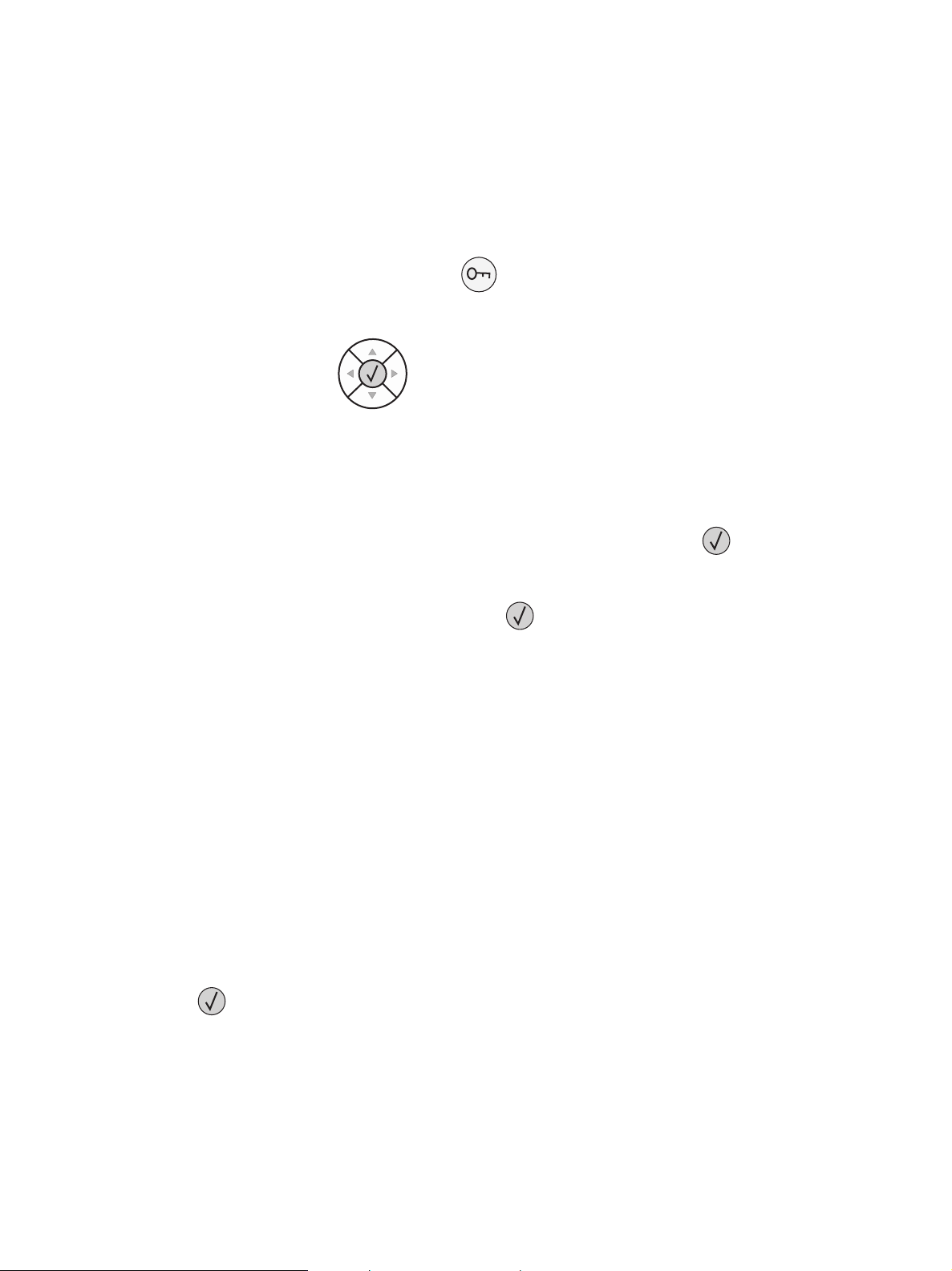
IPDS MENU
9 EMULATION
PAPER HANDLING
MAP INPUT TRAYS
3. Press or to scroll further until 9 is next to the item you need. Press .
In the following example, you select an option called Host Resolution.
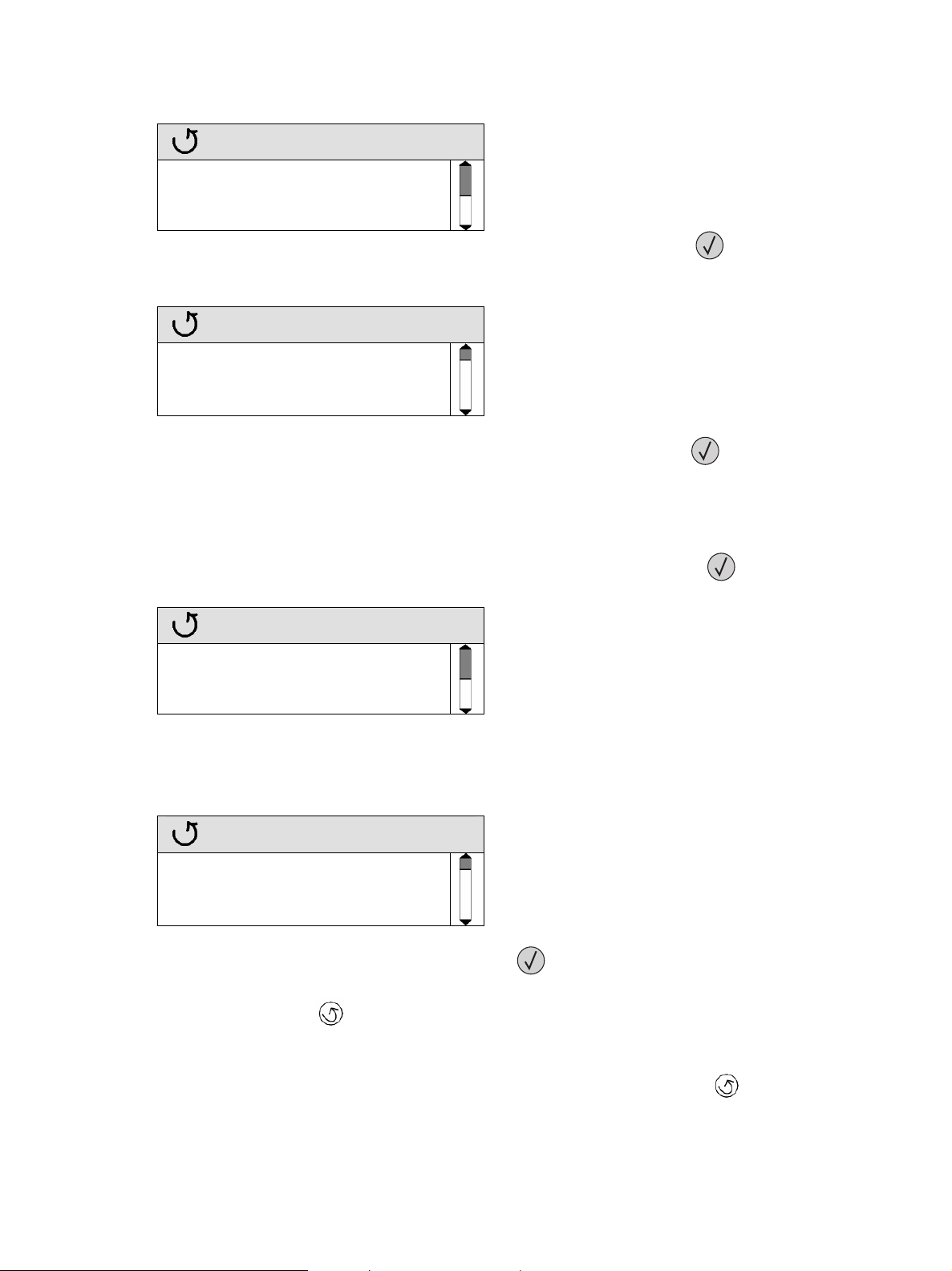
EMULATION
IPDS Emulation
9 Host Resolution
Color Processing
4. Press
or to scroll further until 9 is next to the item you need. Press .
In the following example you select an option setting – “300 dpi” – in the following manner:
The * (asterisk) beside Auto means that Auto is the currently active setting. (It also happens to be
factory default in this example.) Scroll so that
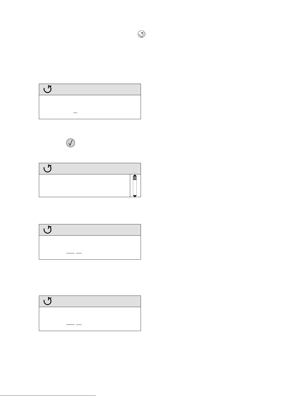
Host Resolution
9 is next to 300 dpi and press .
* Auto
9 300 dpi
240 dpi
5. While the printer is saving the setting, it will display Submitting Selection.
6. When the setting is saved, the display will revert to the previous menu level.
EMULATION
IPDS Emulation
9 Host Resolution
Color Processing
If you want to check the value of the setting, press
currently active setting; in this example “300 dpi”.
Press the Back button
7. If you need to make additional settings within the same menu – such as EMULATION, scroll
through the list. To reach another menu, such as MAP OUTPUT BINS, press
in order to leave the screen without changing the setting.
again. You will see an asterisk * beside the
.
13
Page 14
8. When you are finished, exit by pressing
it several times until Ready appears.
to return to the Ready screen. You may need to press
2.2.3 Example: Changing a Numerical Setting
Example: If you select Option Card Menu > IPDS MENU > MARGINS > TRAY1 > ADJUST Top
Margin, you see the following display:
Top Margin
0
You can either use the numeric pad or the navigation buttons
the value. Press
When the setting is saved, the display will revert to the previous menu level.
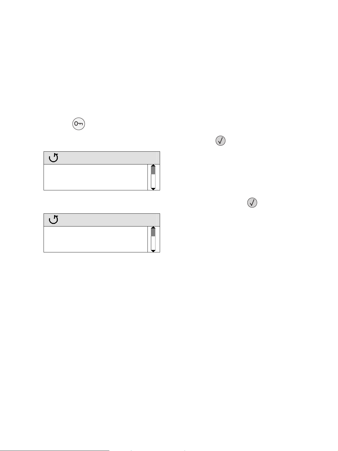
MARGINS
to decrease a value or to increase
to save the desired value.
9 Top Margin
Left Margin
Top Margin Back
Some numerical values contain more than one field. For example, Option Card Menu > IPDS MENU >
EMULATION Default CPI.
Default CPI
10
The value before the decimal point and the value after the decimal point are set independently of each
other. Use the navigation buttons
marked with above the field and below it.
Default CPI
10
. 0
to move between the fields. The currently editable field is
. 0
14
Page 15
2.2.4 Saved Option Changes Become Active on New Session
All saved settings will become active on the next IPDS host session.
If the printer IPDS Timeout is NOT set to “Host Controlled” (Option Card Menu > IPDS MENU >
EMULATION > IPDS Timeout = “Host Controlled”), power the printer OFF and ON to activate the
new settings. For more information on IPDS Timeout, see page
29.
2.2.5 Printing the Menu Settings Page (printers)
Make sure the printer is ON..
11..
Press
22..
Press
33..
Menus
on the operator panel.
until the 9appears next to Reports, and then press .
Paper Menu
9Reports
Settings
4. Press
until the 9appears next to Menu Settings Page, and then press .
Reports
9 Menu Settings Page
Device Statistics
Network Setup Page
5. The message Printing Menu Settings is displayed.
6. The printer returns to Ready state after the list of current active settings prints.
15
Page 16
2.3 Changing IPDS Settings Using the MFP Touch Screen
2.3.1 Accessing the IPDS MENU
The IPDS emulation options and settings are accessed from the IPDS MENU. To reach the menu:
1. Make sure the printer is powered ON and the Ready message appears.
2. Touch the key icon (Menus)
3. Use the icons
4. Touch Option Card Menu.
5. Now you will see a list of options. Touch IPDS MENU.
The same method is used to scroll through lists of menus and options. As you move through the menus,
the top line in the screen shows the navigation path, so that you can always see the name of the group
(menu or option) to which the displayed items (options or settings) belong.
When you select an option, you will either scroll through the list of values presented, as shown in section
2.3.2 on page 16, or enter a number as shown in section 2.3.3 on page 17.
User-selected default settings remain in effect until you save new settings or restore the factory defaults.
Concerning activation of saved settings, see section
or to scroll through the main menus displayed on the screen.
on the touch screen.
2.3.4 on page 17.
2.3.2 Example: Selecting a New Value as a Setting
1. Navigate to IPDS MENU as explained in section
2. For this example, touch EMULATION, which happens to be the first option group on the list.
3. Now you will see a list of options. Touch
item you need. In this example, locate and touch Host Resolution.
4. Now you will see a list of settings. The currently active setting, in this example Auto, is always
presented first. Touch
this example locate and touch “300 dpi”.
orto scroll through the settings until you see the item you need. In
or to scroll through the options until you see the
2.3.1 on page 16.
5. Touch
Note: If you just want to check the active setting of an option without making changes, touch
6. While the printer is saving the setting, Submitting Selection will be displayed.
7. When the setting is saved, the screen will revert to the previous menu level.
16
(Submit).
(Back) and no changes will be saved.
Page 17
8. If you need to change multiple settings within the same menu – such as EMULATION, scroll
through the menu options and change the settings. When you touch
will be saved.
9. When you are finished in this list of menu options, exit by touching
previous menu level or
(Home) to return to the Ready state.
(Submit), all changes
(Back) to return to the
2.3.3 Example: Changing a Numerical Setting
Example: If you select Menus > Option Card Menu > IPDS MENU > MARGINS > TRAY1 >
ADJUST > Top Margin, you see the following on the screen:
Top Margin
Use the navigation icons,
save the desired value.
When the setting is saved, the screen will revert to the previous menu level.
0
to decrease the value orto increase a value. Touch (Submit) to
Some numerical values contain more than one field. For example, Menus > Option Card Menu > IPDS
MENU > EMULATION > Default CPI.
Default CPI 10
The value before the decimal point and the value after the decimal point are set independently of each
other. Set each field independently using the
. 0
above the field and/or the below it.
2.3.4 Saved Option Changes Become Active on New Session
All saved settings will become active on the next IPDS host session.
If the printer IPDS Timeout is NOT set to “Host Controlled” (Menus > Option Card Menu > IPDS
MENU > EMULATION > IPDS Timeout = “Host Controlled”), power the printer OFF and ON to
activate the new settings. For more information on IPDS Timeout, see page
29.
17
Page 18

2.3.5 Printing the Menu Settings Page (MFPs)
Make sure the printer is powered ON and the Ready message appears.
11..
2. Touch
3. Scroll down
4. Now you will see a list of items. Scroll down
5. The message Printing Menu Settings is displayed.
6. The printer returns to Ready state after the list of current active settings prints.
(Menus).
if necessary, then touch Reports.
if necessary, then touch Menu Settings Page.
18
Page 19
3 Setup Operations Reference
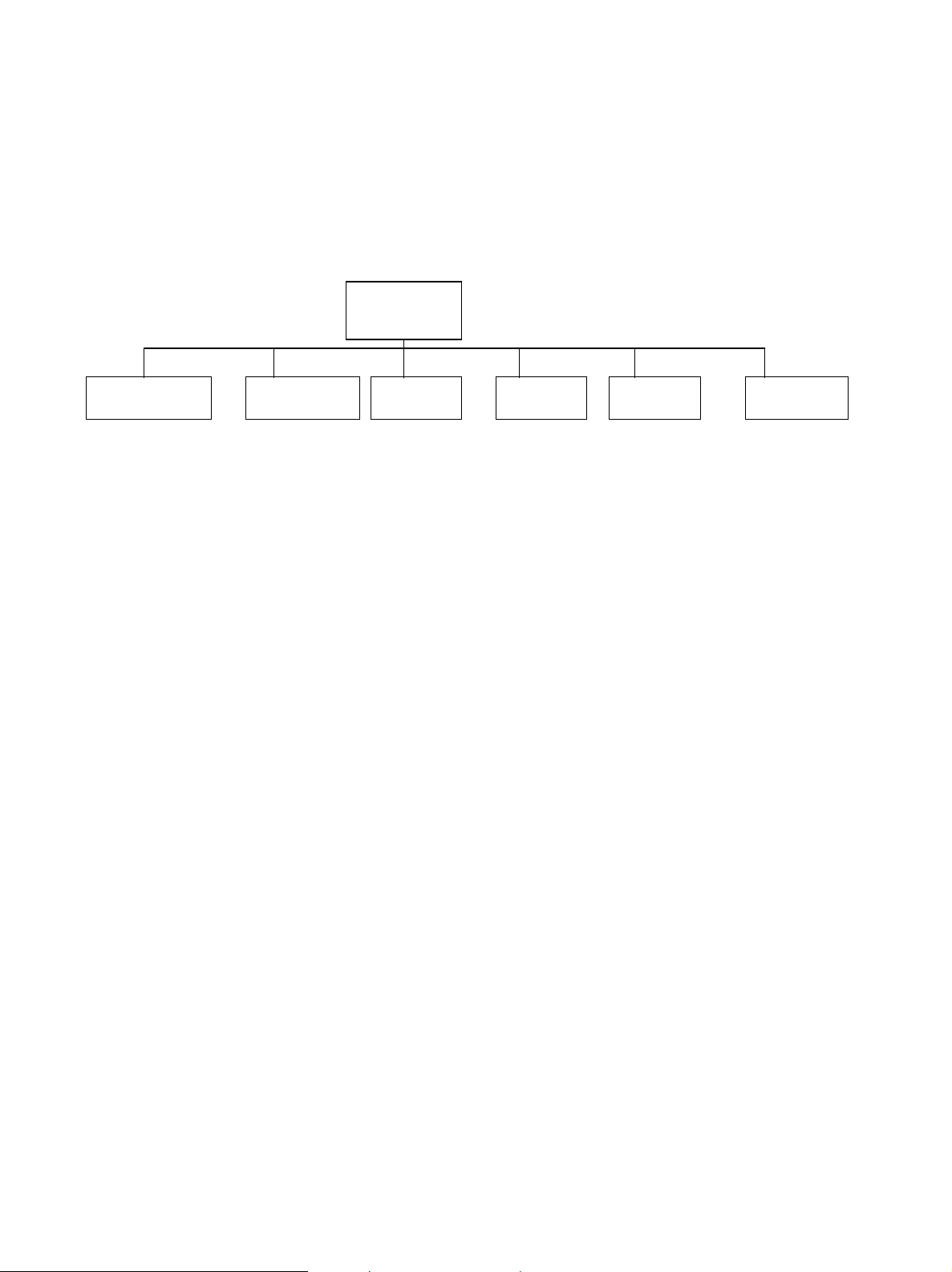
3.1 IPDS MENU - Map of All Options
This section describes the menu structure for the IPDS emulation. Settings are displayed on the printer
under the sub-menus reached from the IPDS MENU, located under the Option Card Menu.
EMULATION
PAPER
HANDLING
IPDS Emulation IPDS Blank Pages Tray Mapping 1 Bin Mapping 1 ALL INPUT TRAYS Capture Fonts
Host Resolution Offset Stacking Tray Mapping 2 Bin Mapping 2 TRAY 1 ADJUST Remove Fonts
Color Processing UNIVERSAL SIZE Tray Mapping 3 Bin Mapping 3 TRAY 2 ADJUST
Text Processing OTHER ENV SIZE Tray Mapping 4 Bin Mapping 4 TRAY 3 ADJUST
Toner Saver * Tray Mapping 5 Bin Mapping 5 TRAY 4 ADJUST
BAR CODE Tray Mapping 6 Bin Mapping 6 TRAY 5 ADJUST
Bar Code Symbol Tray Mapping 7 Bin Mapping 7 MP FEEDER ADJUST
Bar Code Size Tray Mapping 8 Bin Mapping 8 ENV FEEDER ADJ
DEFAULT CODEPAGE Tray Mapping 9 Bin Mapping 9 MANUAL PAPER ADJ
Codepage Version Tray Mapping 10 Bin Mapping 10 MANUAL ENV. ADJ
DEFAULT FGID Bin Mapping 11
Default CPI Bin Mapping 12
Page Counter
Printable Area
Exception Ctrl
Font Ctrl
Font Type
IPDS Print Res
Intervention Req
IPDS Timeout
Print IPDS Fonts
Trace Functions
IPDS Version
* Available only in monochrome products
Note: Only those menu items that are supported by the product are displayed.
IPDS
MENU
MAP INPUT
TRAYS
MAP OUTPUT
BINS
MARGINS
FONT
CAPTURE
In all of the following descriptions an asterisk “*” indicates the default factory value.
19
Page 20

3.2 Overview of EMULATION Menu Options and Values
The following lists all menu options found under the EMULATION menu. Values only display when they
are available on your printer.
An asterisk “*” indicates the default factory value. The selected value for each of these options can be
printed; see
(MFPs) on page
Option name Values
IPDS Emulation Resident*, 3812/3816
Host Resolution Auto*, 240, 300, 600
Color Processing Black (Default on mono printers)
Text Processing Black (Default on mono printers)
Toner Saver Printer Setting*, Host Controlled
BAR CODE
Bar Code Symbol Host Controlled, Always Print*
Bar Code Size Resident*, 4028, 43xx
DEFAULT CODEPAGE Codepages A – E
Arabic Eur 420…Estonian 1157
Codepages F – K
Fin/Swe 278...Int. Set 5 500*...Katakana 290
Codepages L – Z
Latin 2 870…USA/Canada 1140
Codepage Version Version 1*, Version 0
DEFAULT FGID See the option description on page
Default CPI 10.0*, range: 5.0 – 30.0
Page Counter Normal Update*, Early Update
Printable Area Whole Page*, Print Page, Physical Page, Full Page, 4028 Whole Page,
4028 Print Page
Exception Ctrl Report All*, Sup Beyond VPA, Sup Undef Char, Suppress Both
Printing the Menu Settings Page (printers) on page 15 or Printing the Menu Settings Page
18.
Shades of Grey
Color (Default on color printers)
Shades of Grey
Color (Default on color printers)
(Available only in mono printers)
25.
20
Page 21

Font Ctrl Relaxed*, Strict
Font Type Use Scalable*, Use Bitmap
IPDS Print Res 600 dpi, 1200 dpi, 1200 Image Q, 2400 Image Q, 4800 CQ
Default values are dependent on printer or MFP model.
Printers:
Lexmark C770, C772 4800 CQ
Lexmark C780, C782 4800 CQ
Lexmark C920 2400 Image Q
Lexmark C935 2400 Image Q
Lexmark T640, T642, T644 600 dpi
Lexmark W840 600 dpi
MFPs:
Lexmark X644e MFP, X646e MFP 600 dpi
Lexmark X646ef MFP 600 dpi
Lexmark X782e MFP 4800 CQ
Lexmark X850e MFP, X852e MFP,
X854e MFP
Lexmark X940e MFP, X945e MFP 2400 Image Q
Intervention Req Report*, Do not report
IPDS Timeout Host Controlled*, 15 seconds, 30 seconds, 60 seconds, 90 seconds,
2 minutes, 3 minutes, 5 minutes, 10 minutes
Print IPDS Fonts Yes*, No
Trace Functions Disable*, PAR Std. Output, PAR Slot 1 Output, PAR Slot 2 Output,
USB Std. Output, USB Slot 1 Output, USB Slot 2 Output
IPDS Version Display IPDS version number in the operator panel.
A description of each EMULATION menu option follows.
600 dpi
21
Page 22

3.3 EMULATION – Options Descriptions
In the following an asterisk “*” indicates the default factory value. The selected value for each of these
options can be printed; see
Settings Page (MFPs) on page
3.3.1 IPDS Emulation
This option selects the printer emulation to be used when processing IPDS data. It is important to select the
correct emulation before receiving IPDS data. The IPDS Printer and Host Setup Guide includes guidelines
for selecting the emulation.
Resident* This printer’s native emulation
3812/3816 IBM 3812/3816 emulation
Printing with Double Byte Character Set (DBCS) is not supported in the “3812/3816” emulation.
3.3.2 Host Resolution
Specifies the resource resolution support for raster font and IM1 image reported to the host in the XOA
OPC command. The resolution selected determines the printer resident raster fonts which are activated.
For example, 240 dpi raster fonts will be activated with a setting of “240”, but not at the “300” or “600”
setting.
Printing the Menu Settings Page (printers) on page 15 or Printing the Menu
18.
Auto*
240
300
600
Note: If you select the “3812/3816” emulation in the IPDS Emulation option, the Host Resolution is
forced to “240 dpi”.
Reply to host indicates support for IM1 image and any dpi raster fonts. Captured raster
fonts of any resolution are only activated when the activation request is accompanied
by a matching Font Resolution and Metric Technology Triplet.
240 dpi raster font and 240 IM1 image support is reported to the host. Captured raster
fonts of other resolutions will not be activated unless a matching Font Resolution and
Metric Technology Triplet is received with the request.
300 dpi raster font and 300 IM1 image support is reported to the host. Captured raster
fonts of other resolutions will not be activated unless a matching Font Resolution and
Metric Technology Triplet is received with the request.
600 dpi raster font and 600 IM1 image support is reported to the host. Captured raster
fonts of other resolutions will not be activated unless a matching Font Resolution and
Metric Technology Triplet is received with the request.
22
Page 23

3.3.3 Color Processing
Specifies how graphics, image, and bar code color commands are processed. See section 10.5, on page
82, for more information on color printing.
Color
Shades of Grey
Black
Print in full color. (Default for color printers.)
Process color commands and print all colors as shades of grey.
Process color commands and print all colors as black. (Default on mono printers.)
3.3.4 Text Processing
Specifies how text color commands are processed.
Color
Shades of Grey
Black
Print in full color. (Default for color printers.)
Process color commands and print all colors as shades of grey.
Process color commands and print all colors as black. (Default on mono printers.)
3.3.5 Toner Saver
Specifies the action taken on mono printers when the IPDS Print Quality Control command is received.
Printer Controlled*
Host Controlled
Use the values in the printer menu’s Settings > Quality Menu > Toner
Darkness option to control print quality. The value specified in the IPDS Print
Quality Control command is ignored.
Use the value specified in the IPDS Print Quality Control command to control
print quality. See
information.
XOA Print Quality Control on page 79 for additional
3.3.6 BAR CODE
3.3.6.1 Bar Code Symbol
Specifies the action taken when the IPDS data stream specifies suppress printing of the bar code symbol.
The default setting of “Always Print” is useful when older applications have accidentally specified
suppression of the bar code symbol.
Host Controlled
Always Print*
Use the value specified in the Write Bar Code command to control printing of
the bar code.
Always print the bar code. Ignore the value specified in the Write Bar Code
command to control printing of the bar code.
23
Page 24
3.3.6.2 Bar Code Size
This option controls the size of the bar code when using the Resident IPDS emulation. When the
3812/3816 emulation is selected, this setting is ignored. Bar codes will be printed in a size that closely
matches the IBM 3812/3816 family of printers.
Resident*
Prints the bar code in a size that gives best quality on this printer.
4028
Bar codes are printed in a size that closely matches the IBM 4028
printer.
43xx
Bar codes are printed in a size that closely matches the IBM 43xx
family of printers.
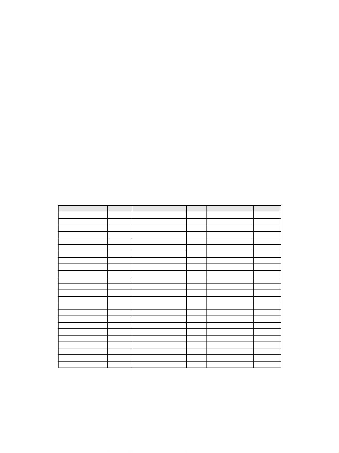
3.3.7 DEFAULT CODEPAGE
• This option defines the default code page with the appropriate character set to be used. The list is a
limited selection of all supported code pages associated with the three types of supported fonts,
which are known as “Compatibility”, “Core Interchange”, and “Coordinated”. For details see
Appendix
Font and Code Page Information, starting on page
Values are in alphabetical order. The operator panel will display codepage options beginning with the
letters A - E, then F – K and L - Z. Select the appropriate path to reach the desired code page. See table
below.
Codepages A – E CPGID Codepages F – K CPGID Codepages L – Z CPGID
Arabic Eur 420 Fin/Swe 278 Latin 2 870
ASCII 367 Fin/Swe 1143 Latin 2 1110
Aus/Ger 273 Fin/Swe Alt 288 Latin 2 1153
Aus/Ger 1141 French/Cat 297 Latin 3 905
Aus/Ger Alt 286 French/Cat 1147 Latin 4 1069
Baltic 1112 Greek 423 Latin 9 Eur 924
Baltic 1156 Greek Eur 875 OCR-A 892
Belgium 274 Hebrew Eur 424 OCR-B 893
Brazil 275 Hebrew Set A 803 PC Multi 850
Can. French 260 Iceland 871 PC Multi Eur 858
Can. French 276 Iceland 1149 PC std 437
Cyrillic 880 Int. Set 5 500* Portugal 037
Cyrillic 1025 Int. Set 5 1148 Portugal 282
Cyrillic 1154 Italy 280 Publishing 361
Den/Nor 277 Italy 1144 Spain/L. Am 284
Den/Nor 1142 Japan (Eng) 281 Spain/L. Am 1145
Den/Nor Alt 287 Katakana 290 Spain Alt 289
Estonian 1122 Turkish Lat 3 905
Estonian 1157 Turkish Lat 5 1026
Turkish 1155
UK 285
UK 1146
USA/Canada 037
USA/Canada 1140
Note 1: The code pages with the designation “Alt” – as well as Can. French 276, ASCII 367, OCR-A 892,
and OCR-B 893 – are supported by one or both of the Compatibility Font Sets. OCR-A 892 and
OCR-B 893 are also supported by the Coordinated Font Set. All of the other code pages in the
above list are in the Core Interchange Font Set.
on
91.
24
Page 25

Note 2: The Euro symbol is supported in code pages 1140-1159, 1153-1158 and in code pages whose text
description includes the designation Eur, such as Arabic Eur 420.
3.3.8 Codepage Version
This option determines which version of a code page is used. Some of the code pages are available in two
versions. Some characters differ between the two versions of the same code page. If characters print
differently than those entered on the keyboard, check the code page version.
Version 1* Use version 1 of appropriate code pages.
Version 0 Use version 0 of appropriate code pages.
3.3.9 DEFAULT FGID
Selects the default Font Global Identifier (FGID) to be used by the IPDS emulation when the host does
not send an FGID at the start of a job.
Select an FGID for the emulation chosen in the IPDS Emulation option. In the table below the
emulations are cross-referenced to pages in the appendix on “Font and Code Page Information”, starting
on page
Option name
Resident FGID
3812/3816 FGID
91. The FGIDs in the referenced tables are available in the operator panel.
Values
See page
When using a CPI value of 10.0 FGID 416 is equal to FGID 11.
See page
3812/3816 is 11*.
93, 97, and 102 for a list of supported FGIDs. Default FGID is 416*.
95, 97, and 102 for a list of supported FGIDs. Default FGID for
3.3.10 Default CPI
Selects the default characters per inch (CPI) to be used by the IPDS emulation when the host does not
send a CPI value at the start of a job. The option does not apply to the fixed pitch fonts.
10.0* Default CPI. The range is 5.0 to 30.0.
3.3.11 Page Counter
This option selects the method used for updating IPDS page counters. (This option is not available on all
printers.)
Normal Update* Jam and stacked page counters are updated when pages are printed.
Early Update All page counters are updated when they are processed but not printed. Pages may
be lost if power or printer failure occurs and when a paper jam occurs.
Note: When “Early Update” is selected, Intervention Required messages are not reported to the IPDS
Host.
25
Page 26

3.3.12 Printable Area
This option defines the printable area on the page and how clipping is performed. Top, bottom, and side
margins for your print jobs are set through your print application.
Whole Page*
Print Page
Physical Page
The printable area is 50 pels (4 mm) inside the physical page. The printable area is
reported to the host. Clipping occurs if data is printed outside the printable area. All
four edges will clip.
The printable area is 50 pels (4 mm) inside the physical page. The printable area is
reported to the host. If the logical page is outside the printable area it is moved down
and to the right. The right and bottom edges will be clipped.
The printable area is the physical page (edge to edge). The physical page printable
area is reported to the host.
Important: Printing within 50 pels of the paper edge may result in poor print
quality. Continual printing within 50 pels (4 mm) of the paper edge is not
recommended. It can result in paper jams due to toner contamination of the paper
path and toner appearing on the back side of duplex jobs. Toner contamination of the
paper path can make more frequent maintenance necessary.
Note 1: The Lexmark T640, T642, T644, and W840 printers, and the Lexmark
X644e MFP, X646e MFP, X646ef MFP, X850e MFP, X852e MFP, X854e
MFP can physically print edge to edge. The logical page is not clipped.
Full Page
4028 Whole Page
4028 Print Page
Note 2: The Lexmark C770, C772, C780, C782, and X782e MFP can print to within
approximately 40 pels (3.4 mm) from all four edges of the paper.
Note 3: The Lexmark C920, can print to within approximately 20 pels (1.7 mm) of
the feed direction top and bottom edge and to within approximately 3 pels
(.25 mm) of the non-feed direction edges.
Note 4: The Lexmark C935 and the Lexmark X940e MFP and X945e MFP can print
to within approximately 4 mm of the leading paper edge and to within
approximately 2 mm of all other edges.
The job is formatted for a page using a printable area of edge to edge. When the
page is printed, the page image is compressed approximately 2% in both the
horizontal and vertical directions.
Note: Full Page is not available on all products. Full page will only appear in
the menu when supported by the printer.
The printable area is 50 pels (4 mm) inside the physical page. A printable area that
more closely matches the values reported by the IBM 4028 printer is reported to the
host. Clipping occurs if data is printed outside the printable area. All four edges will
be clipped.
The printable area is 50 pels (4 mm) inside the physical page. A printable area that
more closely matches the values reported by the IBM 4028 printer is reported to the
host. If the logical page is outside the printable area it is moved down and to the
right. The right and bottom edges will be clipped.
26
Page 27

3.3.13 Exception Control
It is often practical to suppress exception reporting on undefined characters and on position errors
(printing outside the valid printable area, VPA). This option overrides the Exception Handling Control
in the IPDS data stream.
Report All*
Sup Beyond VPA
Sup Undef Char
Suppress Both
No suppression of exceptions. Exception reporting is controlled by the IPDS data
stream.
Exception reporting on position errors (outside VPA) is suppressed. The printer
IPDS emulation will print the IPDS job but not report "08C1" printable area
exceptions or "0411" bar code exceptions to the host.
If an undefined character is found, exception reporting is suppressed. The printer
IPDS emulation will print the IPDS job but not report "0821" undefined character
exceptions to the host.
Both position errors and undefined character exceptions are suppressed.
3.3.14 Font Control
This option defines how strict the reporting will be if a selected font does not correspond to a valid
combination of code page and character set.
Relaxed*
Strict
The printer makes an intelligent decision concerning whether the selected combination of
code page and character set is adequately supported. A “Relaxed” setting will report very
few exceptions. If the selected font is not found, the printer will substitute with the
closest matching font. If a font/code page combination is selected, which is not fully
supported, characters may be missing.
A “Strict” setting reports exceptions when a requested font/code page or substituted
font/code page combination is not valid. The “Strict” setting prints all characters.
3.3.15 Font Type
This option selects the type of fonts used by the printer when a standard resident fixed pitch Courier,
Prestige, or Letter Gothic Font is requested by the host.
Use Scalable*
Use Bitmap
Use printer resident scalable fonts for Courier, Prestige, and Letter Gothic fonts when
bitmap font IDs are received from the host.
Use printer resident bitmap fonts for Courier, Prestige, and Letter Gothic fonts when
bitmap font IDs are received from the host.
27
Page 28

3.3.16 IPDS Print Res
This option defines the internal print resolution used to print IPDS jobs. Host resources received in the
job are converted to the IPDS Print Res setting before printing. This is a separate setting from Print
Resolution menu option in the printer’s Settings > Quality Menu.
This setting alters the quality of text with scalable fonts, bar codes, graphics, and scalable images. Bitmap
fonts and non-scalable images are not affected.
The default setting usually produces the best print quality. Refer to
default settings for all products. Resolutions that are not available on are not displayed.
600 dpi
1200 dpi
1200 Image Q
2400 Image Q
4800 CQ
Memory Considerations
Additional memory above the total recommended may be required when receiving color or complex
pages. Additional memory may also increase print speed. See page
total recommended memory for each resolution setting.
Print at 600 pel resolution.
Print at 1200 pel resolution.
Print with 1200 Image Quality. Select 1200 Image Q when your job contains
grayscaled images that will benefit from enhanced line screening.
Print with 2400 Image Quality. Select 2400 Image Q when your job contains
grayscaled images that will benefit from enhanced line screening.
Print with 4800 Color Quality
IPDS Print Res on page 21 for
118 for information on the minimum
3.3.17 Intervention Required
This option defines if the emulation should report Intervention Required messages to the host. Types of
Intervention Required messages include a paper jam, paper out, cover open or offline message. These
types of messages mean the printer is not ready to print.
Report*
Do Not Report
Note:
28
Report Intervention Required messages to the host. This is the typical setting.
Do not report Intervention Required messages to the host. Used only in special cases.
When Page Counter is set to “Early Update”, Intervention Required messages are
not reported to the host.
Page 29

3.3.18 IPDS Timeout
This option is also called the printer IPDS Timeout. It allows the host to directly control when an IPDS
LAN session with a printer ends (disconnects), or allows the printer IPDS emulation to determine when to
timeout and print jobs waiting on other ports.
Notes: The Option Card Menu > IPDS MENU > EMULATION >IPDS Timeout value is only used
by the printer IPDS emulation when the printer is LAN attached using the Standard Network port
or the MarkNet internal print server.
The Option Card Menu > IPDS MENU > EMULATION > IPDS Timeout value is not active
when the printer is connected to a host through an Adapter for SCS card. The IPDS timeout is
controlled by the Coax or Twinax timeout value on the Adapter for SCS card.
The printer is capable of receiving jobs on multiple printer ports. While the printer is busy printing jobs
from one printer port, jobs on other printer ports remain in a waiting status. When the host disconnects
from the printer or when the printer IPDS emulation times out, the printer automatically switches to
another printer port to start a new job.
“Host Controlled” should be selected as the IPDS Timeout value when the host port value is 9100. The
printer defaults to “Host Controlled” when receiving IPDS jobs on port 9100.
“Host Controlled” or a timeout value (“15 seconds” to “10 minutes”) may be used when the host port
value is 5001 or 9600.
Note: The host port value is specified when configuring the printer parameters on the host. Refer to the
IPDS Printer and Host Setup Guide to determine the port values supported by your printer and
valid host settings compatible with the printer IPDS Timeout values.
Host Controlled*
15 seconds
30 seconds
60 seconds
90 seconds
2 minutes
10 minutes
The printer IPDS emulation remains active until the host disconnects from the
printer. Host timer/timeout values control when the host will disconnect. When the
host disconnects, the printer will print jobs from other printer ports.
Host Timer/Timeout Values and Actions:
The host timer/timeout value should be set to a small value (15 to 30 seconds) so
the host will quickly disconnect after an IPDS job is printed. All IPDS resources
downloaded to the printer will be deleted when the host disconnects. A disabled or
large host timer/timeout value will cause the printer IPDS emulation to remain
active. The BUSY message will remain on the printer operator panel even though the
printer has completed processing and printing the IPDS job.
IPDS emulation timeout values.
These values are only used by the printer IPDS emulation when the host sends IPDS
jobs on port 5001or 9600 to the Standard Network port or a MarkNet internal print
server. If the host does not send another IPDS job or send additional IPDS resource
data to the printer within the printer IPDS timeout value specified, the printer IPDS
emulation will time out, place all IPDS resources in temporary storage (see Storage
of IPDS Resources below), and allow the printer to print jobs from other printer
ports.
Host Timer/Timeout Values and Actions:
While the printer is printing jobs from other printer ports, the host is still connected
to the printer. The host timer/timeout value must be disabled or set to a large value
to prevent the host from disconnecting and deleting the resources downloaded to the
printer. If the
communication errors may also occur.
host timer/timeout value is not disabled or set to a very large value,
29
Page 30

Important: The host timer/timeout value and the printer IPDS Timeout value must
not be set to the same number of seconds. The difference in these values should
always be 30 or more seconds.
Notes:
Up to two sessions are available on port 9600. When all 9600 sessions are active, the printer will
open a new TCP/IP session and immediately close the session.
On port 5001, up to 5 sessions are available when the printer IPDS Timeout is set to “Host
Controlled”. Only two sessions are available when the printer IPDS Timeout is set to “15
seconds” – “10 minutes”. When these two sessions are active, the printer will continually respond
busy to any other TCP/IP session requests.
Storage of IPDS Resources
IPDS resources from the last active port 5001 or 9600 session are temporarily stored in the printer
memory when IPDS Timeout values (“15 seconds” to “10 Minutes”) are selected and the host
timer/timeout values are set to a large value or disabled. Operator actions and processing of other jobs
may cause the resources to be deleted. Events such as the following will cause deletion of the downloaded
resources.
• The host ends the IPDS port 5001 or 9600 session.
• TCP/IP communications is interrupted on the port 5001 or 9600 session.
• Another IPDS session is started on port 5001, 9100, or 9600.
• IPDS MENU option values are changed.
• Processing of a non-IPDS job that requires more memory than is available in printer memory.
• The printer is powered OFF.
If the IPDS resources are deleted, the printer will return a Printer Reset exception to the host. The
message Resources Lost may be displayed for a short time on the printer operator panel. The host will
download the resources again with the next IPDS job.
3.3.19 Print IPDS Fonts
This option prints a font sample list of all the printer resident fonts available in the current emulation
followed by a list of currently captured IPDS fonts.
Yes Print IPDS font list.
No Do not print IPDS fonts.
To prevent loss of host downloaded resources a font list can not be printed when an IPDS session is active
with a host. Note that the printer can be in the Ready state and still have a port 5001 or port 9600 active
LAN IPDS session or a Coax or Twinax IPDS session active through the Adapter for SCS. The message
Active IPDS Ses. Ignoring Request will be displayed when you select Yes on the operator panel and an
IPDS host session is active. You must end the IPDS session from the host or power the printer OFF and
ON to print a font list. Host downloaded resources will be deleted when you end the IPDS session or
power the printer OFF.
Note: This function can not be operated remotely.
30
Page 31

3.3.20 Trace Functions
This option determines if the Trace function is enabled. Trace data is sent to the selected port. Unless you
have a computer running a capture program attached to the port selected to receive the trace data, the
printer may hang BUSY. Print performance is degraded when the trace function is active.
Note: Port selections will only appear when the port is available on the printer. The Trace function is
used by service personnel for trouble shooting and service.
Disable*
PAR Std. Output
PAR Slot 1 Out
PAR Slot 2 Out
USB Std. Output
USB Slot 1 Out
USB Slot 2 Out
Note: This function can not be operated remotely.
Disable Trace
Enable the standard parallel port for trace data output
Enable the optional parallel port in slot 1 for trace data output
Enable the optional parallel port in slot 2 for trace data output
Enable the standard USB port for trace data output
Enable the optional USB port in slot 1 for trace data output
Enable the optional USB port in slot 2 for trace data output
3.3.21 IPDS Version
This option displays the current IPDS version / level.
Note 1: This option can not be used remotely.
Note 2: The IPDS level is also shown on the printed Menu Settings Page. It is found as “IPDS Emulation”
under the Device Information heading. See
or
Printing the Menu Settings Page (MFPs) on page 18.
Printing the Menu Settings Page (printers) on page 15
31
Page 32

3.4 Overview of PAPER HANDLING Menu Options and Values
The following lists all menu options found under the PAPER HANDLING menu. Values only display
when they are available on your printer. An asterisk “*”indicates the default factory value. The selected
value for each of these options can be printed; see
Printing the Menu Settings Page (MFPs) on page 18.
or
Option Name Values
IPDS Blank Pages
Offset Stacking
UNIVERAL SIZE
OTHER ENV SIZE
A description of each PAPER HANDLING option follows.
Print*, Do Not Print
Host Controlled*, Disabled
The valid values for Paper Length and Paper Width are listed in section
on page
The valid values for Envelope Length and Envelope Width are listed in
section
33.
3.5.4 on page 34.
Printing the Menu Settings Page (printers) on page 15
3.5.3
32
Page 33

3.5 PAPER HANDLING Menu – Option Descriptions
In the following an asterisk “*” indicates the default factory value. The selected value for each of these
options can be printed; see
Settings Page (MFPs) on page
3.5.1 IPDS Blank Pages
This option determines if blank pages in IPDS jobs are printed.
Print* Print all IPDS pages.
Do Not Print Skip printing of blank IPDS pages. Duplex pages are skipped only if both sides are blank.
3.5.2 Offset Stacking
This option controls the offset stacking function. It is only displayed when offset stacking is supported in
the printer standard bin or when an optional finisher with offset stacking capability is installed. Offset
stacking is only available in selected bins and may be limited to selected media.
Bin selection has a higher priority than offset stacking commands in the IPDS job. The job must be routed
to a bin that supports offset stacking and have offset stacking specified in the job before offset stacking
will be performed.
Printing the Menu Settings Page (printers) on page 15 or Printing the Menu
18.
See section
Host Controlled*
Disabled
5.1 on page 53 for additional information on offset stacking.
Offset stacking is controlled by the commands received in the IPDS job.
Offset stacking is not performed. Offset stacking commands received in the
IPDS jobs are ignored.
3.5.3 UNIVERSAL SIZE
The IPDS emulation uses the paper size setting specified in the printer menu to determine the size loaded.
The paper size is returned to the host. A printer paper size of “Universal” is displayed in the printer menu
when a non-standard size paper is detected in an auto size sensing tray or is selected as the paper size
loaded into a non-size sensing tray or feeder.
This option allows you to specify the physical paper size returned to the host when a non-standard paper
size is loaded. The paper size is specified in 300 dots per inch.
Important: A 34 Short Paper, 34 Wrong Paper Size, or paper jam error may be displayed if printing
occurs past the length of the physical paper. You should specify the actual paper size to avoid errors.
33
Page 34

Product Menu Option Value
Range
Lexmark C920
Lexmark C770, C772, C780, C782,
C935
Lexmark T640, T642, T644
Lexmark X644e MFP, X646e MFP,
X646ef MFP, X782e MFP, X850e
MFP, X852e MFP, X854e MFP,
X940e MFP, X945e MFP
Lexmark W840
UNIVERSAL SIZE >
Paper Length
UNIVERSAL SIZE >
Paper Width
UNIVERSAL SIZE >
Paper Length
UNIVERSAL SIZE >
Paper Width
UNIVERSAL SIZE >
Paper Length
UNIVERSAL SIZE >
Paper Width
5100*,
1749 to 6824
3510*,
1062 to 3510
4200*,
1500 to 4200
2550*,
825 to 2703
6000*
1200 to 6000
3510*
825 to 3510
Function
Specifies Universal paper
length. See note below.
Specifies Universal paper
width. See note below.
Specifies Universal paper
length. See note below.
Specifies Universal paper
width. See note below.
Specifies Universal paper
length. See note below.
Specifies Universal paper
width. See note below.
Note: The printer paper trays and feeders are limited to feeding of specific media sizes. Refer to your
printer documentation when loading a non-standard media size to determine if that media size can
be fed from that tray or feeder.
Note: The printer Paper Menu > Universal Setup settings for paper width and paper height must be set
equal to the IPDS MENU > PAPER HANDLING > UNIVERSAL SIZE menu settings.
Otherwise, a paper jam, 34 Short Paper or 34 Wrong Paper Size error may be displayed.
Conversion example:
3.5.4 OTHER ENV SIZE
The IPDS emulation uses the envelope size setting specified in the printer menu to determine the
envelope size loaded. The envelope size is returned to the host. A printer envelope size of “Other
Envelope” may be selected in some printer menus when a non-standard size envelope is loaded into a
non-size sensing tray or feeder.
This option allows you to specify the envelope size returned to the host when “Other Envelope” is
selected in the printer menu as the envelope size. The envelope size is specified in 300 dots per inch. See
the conversion example for UNIVERSAL SIZE (section
Important: A 34 Short Paper Error may be displayed if printing occurs past the length of the physical
envelope. You must specify the actual envelope size to avoid incorrect text positioning or clipping of text.
Some printers do not report an error when the size is incorrect and the text is clipped.
3.5.3).
34
Page 35

Product Menu Option Value Range Function
Lexmark C770, C772, C780, C782,
C920, C935
Lexmark T640, T642, T644,
Lexmark X644e MFP, X646e MFP,
X646ef MFP, X782e MFP, X850e MFP,
X852e MFP, X854e MFP, X940e MFP,
X945e MFP
Lexmark W840
OTHER ENV SIZE
> Envelope Length
OTHER ENV SIZE
> Envelope Width
OTHER ENV SIZE
> Envelope Length
OTHER ENV SIZE
> Envelope Width
4200*,
1500 to 4200
2550*,
825 to 2550
5100*,
1200 to 5100
3510*,
825 to 3510
Specifies Other Envelope
length.
See note below.
Specifies Other Envelope
width.
See note below.
Specifies Other Envelope
length.
See note below.
Specifies Other Envelope
width.
See note below.
Note: The printer trays and feeders are limited to feeding of specific media sizes. Refer to your printer
documentation when loading a non-standard media size to determine if that media size can be fed
from that tray or feeder.
Feed directions are shown in the illustrations on page
36.
35
Page 36

Envelope feed directions
Lexmark C770 and C772
Lexmark C780 and C782
Lexmark T640, T642, and T644
Lexmark X644e MFP and X646e MFP
Lexmark X646ef MFP
Lexmark X782e MFP
Lexmark C920
Lexmark C935
Lexmark X940e MFP and X945e MFP
Lexmark W840
Lexmark X850e MFP, X852e MFP,
and X854e MFP
Feed Direction
x
y
Feed Direction
Feed Direction
x
y
Address
Address
Address
Address
Leading Edge
of Envelope
Leading Edge
of Envelope
Address
Address
y
x
Leading Edge
of Envelope
x = Left Margin y = Top Margin
36
Page 37

3.6 MAP INPUT TRAYS Menu Options
This option defines the mapping of the host's request for a physical feeder or input tray in the printer. Any
host input source can be mapped to any printer input source. The printer input source is mapped to an
IPDS host number. Input sources include the multi-purpose feeder, envelope feeder, manual paper feed,
and manual envelope feed.
Some models may not support all printer input sources listed below. The optional sources will only be
displayed when installed on the printer. The Tray x Hp values are only displayed when the an optional
finisher that supports hole punching is installed. Pages can be hole punched using the “Tray x Hp” value
settings. See
You can configure up to 10 mappings. Select a Tray Mapping x in the MAP INPUT TRAYS menu
group (the value x represents any given Tray Mapping number). This displays a list of Tray Values which
identify the available printer input sources. When you select a Tray Value, the operator panel displays a
numerical setting screen to set the IPDS tray selection number that will select that printer input source.
Tray Mapping 1 through
Tray Mapping 10
Tray Value
Tray 1, Tray 1 Hp, Tray 2, Tray 2 Hp, Tray 3, Tray 3 Hp, Tray 4, Tray 4
IPDS Tray Selection
Number Values
A typical relationship between IPDS Numbers and input sources would be
Hole Punching on page 66 for additional information.
Tray Mapping x is a sub-menu selection item. Each item refers to the
number of the mapping, not to the physical printer tray.
Tray Values specify the physical printer tray. The tray values specified
below are available under the specified printer’s Tray Mapping submenu when the physical tray is installed and available.
Check your printer documentation for information on optional tray and
feeder support. Values that may be displayed when trays on feeders are
installed are shown below.
Hp, Tray 5, Tray 5 Hp, Env Feeder, Manual Paper, Manual Paper Hp,
Manual Env, No Map
The value range for the IPDS Tray Selection Number is 0 to 255. If an
IPDS tray selection number is mapped (used) twice, the lowest tray
mapping (if available) is used.
Tray Map. No.
Tray Mapping 1 Tray 1 0
Tray Mapping 2 Tray 2 1
Tray Mapping 3 Tray 3 2
Tray Mapping 4 Tray 4 3
Tray Mapping 5 Tray 5 4
Tray Mapping 6 Envelopes (Feeder) 64 (40H)
Tray Mapping 7 Envelopes (Manual) 64 (40H)
Tray Mapping 8 Manual Paper 99 (63H)
Tray Mapping 9 MP Feeder 98 (62H)
Tray Mapping 10 No Map ---
Æ
Input Source Value
Æ
IPDS (Tray Selection) Number
Note: The labels Tray Mapping 1 - Tray Mapping 10 refer to the number of the mapping, not the
physical tray.
37
Page 38

Important!
For MAP INPUT TRAYS to work correctly, the Paper Size/Type for each printer input tray must be set
differently in the printer’s Paper Menu. See example 1 below. The only time you set the PAPER TYPE
the same for more than one input tray is when you want to link the input trays involved. See example 2.
Examples of tray mapping
Example 1 - Making a higher capacity input tray the default tray
You may want to use one of the higher capacity input trays for IPDS 0. To swap the IPDS tray selection
number for Tray 1 and Tray 2, you will need to do the following:
1. Set Tray Mapping 2 for Tray 2 to IPDS 0.
2. Set Tray Mapping 1 for Tray 1 to IPDS 1.
This will give you:
Tray Mapping 1 = IPDS 1 mapped to Tray 1
Tray Mapping 2 = IPDS 0 mapped to Tray 2
Note: You must set the Paper Size/Type for the high capacity tray to a different value from all other
trays. For instance, you could choose a different custom paper type. This setting is found in the
printer’s Paper Menu.
Example 2 - Linking input trays
To link multiple input trays as one big input tray, you need to make changes under the printer's Paper
Menu. You need to set the same Paper Size/Type for each of the trays you want to link to the same
value.
For example, the host expects colored paper in Tray 1 and you want to link Tray 2 and Tray 3, which
have plain paper. Do the following:
Leave the MAP INPUT TRAYS at their defaults:
Tray Mapping 1 = IPDS 0 mapped to Tray 1
Tray Mapping 2 = IPDS 1 mapped to Tray 2
Tray Mapping 3 = IPDS 2 mapped to Tray 3
Insert letter-size colored paper in Tray 1. Insert letter-size plain paper in Trays 2 and 3.
The paper size is detected by the printer:
Tray 1 Size = Letter
Tray 2 Size = Letter
Tray 3 Size = Letter
Set the paper type for each tray. In this example, you would configure the three trays as follows:
Tray 1 Type = Colored Paper
Tray 2 Type = Plain Paper
Tray 3 Type = Plain Paper
38
Page 39

The printer will feed paper from Tray 3 when Tray 2 is empty.
Example 3 - Understanding what happens when an IPDS tray selection number is mapped twice
If an IPDS tray selection number is mapped (used) twice, the lowest tray mapping number is activated (if
available). For example if Tray Mapping 6 and 7 both map to IPDS 64 as shown below, the printer will
select media from the Env Feeder.
Tray Mapping 6 = IPDS 64 mapped to Env Feeder
Tray Mapping 7 = IPDS 64 mapped to Manual Env
In other words, the printer attempts to map to (select media from) the Env Feeder first, and if it is not
installed, the printer defaults to Manual Env.
39
Page 40

3.7 MAP OUTPUT BINS Menu Options
This option defines the mapping of the host's request for a physical output bin in the printer. The printer
physical bin is mapped to an IPDS output bin selection number that is specified in the IPDS data stream.
Printer output bins include the top of the printer (standard bin) and optional output bins that attach to the
printer.
Some printer models may not support all bins listed. The optional printer output bin value will only be
displayed when the physical output bin is installed on the printer. Bin x Hp values and Fin High Cap Hp
values are only displayed when an optional finisher that supports hole punching is installed. Pages can be
hole punched using the “Hp” value settings. See
You can configure up to 12 mappings. This allows the Standard Bin, up to 10 optional bins, and a special
high capacity setting (Fin High Cap) explained in section
Select a Bin Mapping x in the MAP OUTPUT BINS menu group (the value x represents any given Bin
Mapping number). This displays a list of Output Bin Values that identify the available printer physical
bins. When you select an Output Bin Value, the operator panel displays a numerical setting screen to set
the IPDS bin selection number that will select that physical bin.
Hole Punching on page 66 for additional information.
3.7.1 on page 40.
Bin Mapping 1 through
Bin Mapping 12
Output Bin Value
IPDS Bin Selection
Number Values
Bin Mapping x is a sub-menu selection item.
Each item refers to the number of the mapping, not to the physical
printer output bin.
Output Bin Values specify the physical printer output bin. The output
bin values specified below are available under the specified printer’s
Bin Mapping sub-menu when the physical bin is installed and
available. General
page
40.
Check your printer documentation for information on optional bin
and finisher support. Values that may be displayed when optional
bins or optional finishers are installed are shown below.
Standard Bin, Bin 1, Bin 2, Bin 3, Bin 4, Bin 5, Bin 6, Bin 7, Bin 8,
Bin 9, Bin 10, Fin High Cap, Bin 1 Hp, Bin 2 Hp, Fin High Cap Hp,
No Map
The value range for the IPDS Bin Selection Number is 1 to 255. If
an IPDS bin selection number is mapped (used) twice, the lowest bin
mapping (if available) is used. General
Selection Numbers are found on page
Descriptions of Output Bin Values are found on
Descriptions of IPDS Bin
41.
3.7.1 Descriptions of Output Bin Values
Output bin values are associated with physical bins on the printer. Bin values will only appear in the
menu when the physical bin is available on the printer.
A description for each output bin value is given below.
Std Bin – Selects the printer standard output bin.
40
Page 41

Output Bin 1 – Output Bin 10 – Selects additional standard output bins available on the printer or
optional physical output bins when installed.
Fin High Cap – Selects the optional finisher output bin with the highest capacity. The order of option
installation does not affect the physical bin associated with the Fin High Cap bin value. This value is
always associated with the highest capacity physical bin of the optional finisher.
Bin Mapping 12 = Fin High Cap = IPDS number 25 is a default value on all printers. Assuming the
optional finisher is installed and this default value is not changed, jobs that select IPDS bin number 25 on
the host will always be routed to the finisher bin with the highest capacity.
When hole punching is available in a physical bin, bin selection values may be followed by ‘Hp’ which
indicates hole punching is available. Examples are: Output Bin 1 Hp, Output Bin 2 Hp, Fin High Cap Hp.
When a value with ‘Hp’ is selected, all pages in an IPDS job routed to this bin are hole punched. See
Punching on page
66 for additional information.
Hole
3.7.2 Descriptions of IPDS Bin Selection Numbers
Host applications select printer physical bins by sending IPDS bin selection numbers ranging from 1 to
255. These IPDS bin numbers may be mapped to any physical bin on the printer by changing the printer
physical bin selected by the IPDS bin selection number. Assuming printer default output bin mapping,
when IPDS number 1 is received in an IPDS job, the pages are routed to the printer Standard Bin. When
IPDS bin selection number 2 is received in an IPDS job, the pages are routed to the second printer
physical output bin.
Bin Mapping 12 = Fin High Cap = IPDS bin selection number 25, is a default value on all printers.
Assuming the optional finisher is installed and this default value is not changed, jobs that select IPDS bin
selection number 25 on the host will always be routed to the finisher bin with the highest capacity.
3.7.3 Default Bin Mapping
The default bin mapping shown below represents a typical relationship between IPDS output bin selection
numbers and the printer physical output bins. The default mapping when optional output bins are installed
on the printer is shown in the table below for all printers. In the table below, the labels Bin Mapping 1-
Bin Mapping 12 refer to the number of the mapping, not the printer physical output bin. All printers do
not support ten optional output bins. Default settings will be assigned for all output bins available on your
printer.
Bin Mapping No.
Bin Mapping 1 Standard Bin 1
Bin Mapping 2 Bin 1 2
Bin Mapping 3 Bin 2 3
Bin Mapping 4 Bin 3 4
Bin Mapping 5 Bin 4 5
Bin Mapping 6 Bin 5 6
Bin Mapping 7 Bin 6 7
Bin Mapping 8 Bin 7 8
Bin Mapping 9 Bin 8 9
Bin Mapping 10 Bin 9 10
Bin Mapping 11 Bin 10 11
Bin Mapping 12 Fin High Cap 25
Æ
Output Bin Value
Æ
IPDS (Bin Selection) Number
41
Page 42

3.8 MARGINS Menu Options
Use margin settings to adjust the position of the page image. Margin settings, which could be compared to
movements of the tractor feeder and paper knob of a matrix printer, affect all IPDS jobs and are not
affected by IPDS commands in the job.
The input tray and input feeder Left Margin and Top Margin option settings should not be confused
with the IPDS left and top margin settings sent from the host. Input tray Left Margin settings adjust the
page image left or right in relation to the media leading reference edge as it is fed through the printer.
Input tray Top Margin settings adjust the page image up or down in relation to the media leading
reference edge as it is fed through the printer. The illustrations below apply to paper and envelopes when
a finisher is not installed.
Short Edge Fed Media
Leading Reference Edge
Text Rotation = 0
Short Edge Fed Media
Leading Reference Edge
Text Rotation = 90
(0,0)
Long Edge
Fed Media
Leading
Reference
Edge
Input Tray Top Margin
First Line
Second Line
Input Tray Left Margin
(0,0)
Long Edge
Fed Media
Leading
Reference
Edge
Input Tray Top Margin
Second Line
Input Tray Left Margin
First Line
Margins may be adjusted for all input trays and feeders using the ALL INPUT TRAYS menu. Additional
adjustments may be made to the ALL INPUT TRAYS margin settings for an individual tray or feeder
using the tray or feeder specific margin menu. Most often, the ALL INPUT TRAYS margin settings will
remain at the default setting of zero and adjustments will be made using the specific tray or feeder margin
menu. The ALL INPUT TRAYS margin adjustment PLUS the specific tray or feeder margin adjustment
determines the total margin adjustment for a specific tray or feeder.
Margin Adjustment = ALL INPUT TRAYS setting + Specific Tray / Feeder Setting
The IPDS emulation is limited by the printer’s printable area. The MARGINS menu may be used to
adjust page images outside the valid printable area. The page image will be clipped. Valid Printable Area
(VPA) exception conditions will not be reported to the host.
Margin adjustments are in 1/300ths of an inch.
See the Examples below.
The selected value for each of these options can be printed; see
on page
15 or Printing the Menu Settings Page (MFPs) on page 18.
Printing the Menu Settings Page (printers)
42
Page 43

Example 1 – Margins
The ALL INPUT TRAYS Left Margin is set to the default of 0. The TRAY 1 ADJUST Left Margin is
set to +25. This adjusts the page image left margin for all pages printed from tray 1 by 25/300ths of an
inch to the right of the margin specified in the IPDS job.
Example 2 – Margins
The ALL INPUT TRAYS Left Margin has been adjusted to –25. This moves the left margin for pages
printed for all IPDS jobs 25/300ths of an inch to the left. The TRAY 1 ADJUST Left Margin has been
adjusted to +25. For tray 1, the additional TRAY 1 ADJUST Left Margin value will also be used to
adjust the left margin. The tray 1 left margin adjustment will be zero for pages printed from tray 1. The
ALL INPUT TRAYS Left Margin adjustment PLUS the TRAY 1 ADJUST Left Margin adjustment
equals the total left margin adjustment. {–25 pels +25 pels = 0 adjustment}
Margin and Tray Linking Interaction
When trays are linked, the margins set in the ALL INPUT TRAYS menu and the margins set for the tray
specified in the IPDS data stream will be used to adjust the page image on the paper.
Example 1 – Margin and Tray Linking
Tray 1 is requested as the input source from the host. If tray 1 and tray 2 are linked and tray 1 runs out of
paper, paper will be pulled from tray 2. The margin adjustments applied when printing from tray 2 will be
the ALL INPUT TRAYS margins PLUS the TRAY 1 ADJUST margins set for the requested IPDS
input source (tray 1).
Example 2 – Margin and Tray Linking
Tray 2 is requested as the input source from the host. If tray 1 and tray 2 are linked and tray 2 runs out of
paper, paper will be pulled from tray 1. The margin adjustments applied when printing from tray 1 will be
the ALL INPUT TRAYS margins PLUS the TRAY 2 ADJUST margins set for the requested IPDS
input source (tray 2).
Example 3 – Margin and Tray Linking
Tray 2 is requested as the input source from the host. If tray 2, tray 3, and tray 4 are linked and tray 2 runs
out of paper, paper will be pulled from tray 3 until it is empty and then from tray 4. The margin
adjustments applied when printing from tray 3 or tray 4 will be the ALL INPUT TRAYS margins PLUS
the TRAY 2 ADJUST margins set for the requested IPDS input source (tray 2).
Margin and Tray Mapping Interaction
When the host’s IPDS Tray Selection Number has been mapped to another input source using the MAP
INPUT TRAYS option, the value of the MAP INPUT TRAYS option will determine the margin
adjustment applied to pages printed from the selected tray.
Example – Margin and Tray Mapping
The host input source IPDS Tray Selection Number 1 normally selects the printer physical tray 2. If IPDS
Tray Selection Number 1 has been mapped to Tray 1, the TRAY 1 ADJUST margin values will be
applied to all pages in a job that have tray 2 specified as the input source.
Each margin menu option has four sub-menus. The exception is the envelope menu options, which have
only two. The available margin menu options and their sub-menus are shown below.
43
Page 44

Margin menu option Top Margin Left
Margin
ALL INPUT TRAYS
TRAY 1 ADJUST
TRAY 2 ADJUST
TRAY 3 ADJUST
TRAY 4 ADJUST
TRAY 5 ADJUST
MP FEEDER ADJUST
ENV FEEDER ADJ
MANUAL PAPER ADJ x x x x
MANUAL ENV ADJ
x x x x
x x x x
x x x x
x x x x
x x x x
x x x x
x x x x
x x
x x
Top
Margin
Back
Left
Margin
Back
Margin menu options will only appear when the printer option is installed or when the printer supports
feeding the media. The following sections describe each of the margin menu options.
3.8.1 ALL INPUT TRAYS Menu
This menu option allows the top and left margins for simplex and duplex pages to be adjusted. Margin
settings of this menu option apply to pages printed from any tray or feeder. Adjustments to the ALL
INPUT TRAYS margin settings can be made by adjusting the individual margin settings for a specific
tray or feeder. Negative values indicate a decrease in the margin value from the default margin of zero.
ALL INPUT
TRAYS
Left Margin
Top Margin
Left Margin Back
Top Margin Back
Value Function Performed
0*,
-127 to 127
0*,
-127 to 127
0*,
-127 to 127
0*,
-127 to 127
Adjusts the page front side left margin for pages printed
from all input trays and feeders.
Adjusts the page front side top margin for pages printed
from all input trays and feeders.
Adjusts the duplex page back side left margin for pages
printed from all input trays and feeders.
Adjusts the duplex page back side top margin for pages
printed from all input trays and feeders.
3.8.2 TRAY 1 ADJUST Menu
This menu option allows additional adjustment to the top and left margins for simplex and duplex pages
printed from tray 1. TRAY 1 ADJUST margin settings adjust the value of the ALL INPUT TRAYS
corresponding margin setting for all pages printed from tray 1. See margin settings examples under
MARGINS Menu Options on page 42 for additional information.
TRAY 1 ADJUST Value Function Performed
Left Margin
Top Margin
Left Margin Back
Top Margin Back
0*,
-127 to 127
0*,
-127 to 127
0*,
-127 to 127
0*,
-127 to 127
Adjusts the page front side left margin for
pages printed from tray 1.
Adjusts the page front side top margin for
pages printed from tray 1.
Adjusts the duplex page back side left
margin for pages printed from tray 1.
Adjusts the duplex page back side top
margin for pages printed from tray 1.
44
Page 45

3.8.3 TRAY 2 ADJUST Menu
This menu option allows additional adjustment to the top and left margins for simplex and duplex pages
printed from tray 2. TRAY 2 ADJUST margin settings adjust the value of the ALL INPUT TRAYS
corresponding margin setting for all pages printed from tray 2. See margin settings examples under
MARGINS Menu Options on page 42 for additional information.
TRAY 2 ADJUST Value Function Performed
Left Margin 0*,
-127 to 127
Top Margin 0*,
-127 to 127
Left Margin Back 0*,
-127 to 127
Top Margin Back 0*,
-127 to 127
Adjusts the page front side left margin for
pages printed from tray 2.
Adjusts the page front side top margin for
pages printed from tray 2.
Adjusts the duplex page back side left
margin for pages printed from tray 2.
Adjusts the duplex page back side top
margin for pages printed from tray 2.
3.8.4 TRAY 3 ADJUST Menu
This menu option allows additional adjustment to the top and left margins for simplex and duplex pages
printed from tray 3. TRAY 3 ADJUST margin settings adjust the value of the ALL INPUT TRAYS
corresponding margin setting for all pages printed from tray 3. See margin settings examples under
MARGINS Menu Options on page 42 for additional information.
TRAY 3 ADJUST Value Function Performed
Left Margin 0*,
-127 to 127
Top Margin 0*,
-127 to 127
Left Margin Back 0*,
-127 to 127
Top Margin Back 0*,
-127 to 127
Adjusts the page front side left margin for
pages printed from tray 3.
Adjusts the page front side top margin for
pages printed from tray 3.
Adjusts the duplex page back side left
margin for pages printed from tray 3.
Adjusts the duplex page back side top
margin for pages printed from tray 3.
3.8.5 TRAY 4 ADJUST Menu
This menu option allows additional adjustment to the top and left margins for simplex and duplex pages
printed from tray 4. TRAY 4 ADJUST margin settings adjust the value of the ALL INPUT TRAYS
corresponding margin setting for all pages printed from tray 4. See margin settings examples under
MARGINS Menu Options on page 42 for additional information.
TRAY 4 ADJUST Value Function Performed
Left Margin 0*,
-127 to 127
Top Margin 0*,
-127 to 127
Left Margin Back 0*,
-127 to 127
Top Margin Back 0*,
-127 to 127
Adjusts the page front side left margin for
pages printed from tray 4.
Adjusts the page front side top margin for
pages printed from tray 4.
Adjusts the duplex page back side left
margin for pages printed from tray 4.
Adjusts the duplex page back side top
margin for pages printed from tray 4.
45
Page 46

3.8.6 TRAY 5 ADJUST Menu
This menu option allows additional adjustment to the top and left margins for simplex and duplex pages
printed from tray 5. TRAY 5 ADJUST margin settings adjust the value of the ALL INPUT TRAYS
corresponding margin setting for all pages printed from tray 5. See margin settings examples under
MARGINS Menu Options on page 42 for additional information.
TRAY 5 ADJUST Value Function Performed
Left Margin 0*,
-127 to 127
Top Margin 0*,
-127 to 127
Left Margin Back 0*,
-127 to 127
Top Margin Back 0*,
-127 to 127
Adjusts the page front side left margin for
pages printed from tray 5.
Adjusts the page front side top margin for
pages printed from tray 5.
Adjusts the duplex page back side left
margin for pages printed from tray 5.
Adjusts the duplex page back side top
margin for pages printed from tray 5.
3.8.7 MP FEEDER ADJUST Menu
This menu option allows additional adjustment to the top and left margins for simplex and duplex pages
printed from the multipurpose feeder. MP FEEDER ADJUST margin settings adjust the value of the
ALL INPUT TRAYS corresponding margin setting for all pages printed from the MP feeder.
See margin settings examples under
MP FEEDER ADJUST Value Function Performed
Left Margin 0*,
Top Margin 0*,
Left Margin Back 0*,
Top Margin Back 0*,
MARGINS Menu Options on page 42 for additional information.
Adjusts the page front side left margin for
-127 to 127
-127 to 127
-127 to 127
-127 to 127
pages printed from the MP feeder.
Adjusts the page front side top margin for
pages printed from the MP feeder.
Adjusts the duplex page back side left
margin for pages printed from the MP
feeder.
Adjusts the duplex page back side top
margin for pages printed from the MP
feeder.
3.8.8 ENV FEEDER ADJ Menu
This menu option allows additional adjustment to the top and left margins for jobs printed from the
envelope feeder. ENV FEEDER ADJ margin settings adjust the value of the ALL INPUT TRAYS
corresponding margin setting for all pages printed from the envelope feeder.
ENV FEEDER ADJ Value Function Performed
Left Margin 0*,
-127 to 127
Top Margin 0*,
-127 to 127
Adjusts the page front side left margin for
envelopes printed from the envelope feeder.
Adjusts the page front side top margin for
envelopes printed from the envelope feeder.
46
Page 47

3.8.9 MANUAL PAPER ADJ Menu
This menu option allows additional adjustment to the top and left margins for simplex and duplex pages
printed from the manual tray. MANUAL PAPER ADJ margin settings adjust the value of the ALL
INPUT TRAYS corresponding margin setting for all pages printed from the manual tray.
MANUAL PAPER ADJ Value Function Performed
Left Margin 0*,
-127 to 127
Top Margin 0*,
-127 to 127
Left Margin Back 0*,
-127 to 127
Top Margin Back 0*,
-127 to 127
Adjusts the page front side left margin for pages
printed from the manual tray.
Adjusts the page front side top margin for pages
printed from the manual tray.
Adjusts the duplex page back side left margin for
pages printed from the manual tray.
Adjusts the duplex page back side top margin for
pages printed from the manual tray.
3.8.10 MANUAL ENV ADJ Menu
This menu option allows additional adjustment to the top and left margins for jobs printed from the
manual tray. MANUAL ENV ADJ margin settings adjust the value of the ALL INPUT TRAYS
corresponding margin setting for all envelopes printed from the manual tray. See margin settings
examples under
MARGINS Menu Options on page 42 for additional information.
MANUAL ENV ADJ Value Function Performed
Left Margin 0*,
-127 to 127
Top Margin 0*,
-127 to 127
Adjusts the page front side left margin for envelopes
printed from the manual tray.
Adjusts the page front side top margin for envelopes
printed from the manual tray.
47
Page 48

3.9 Overview of the FONT CAPTURE Menu Options
The following lists all menu options found under the FONT CAPTURE menu, which only displays if a
user flash memory or a disk is installed in the printer. An asterisk “*”indicates the default factory value.
The selected value for each of these options can be printed; see
on page
(see section
Option name Values
Capture Fonts Disable*, Save To Disk, Save To Flash
Remove Fonts No*, Yes
A description of each FONT CAPTURE option follows.
15 or Printing the Menu Settings Page (MFPs) on page 18. In addition, if you “Print IPDS fonts”
3.3.19 on page 30), the printout will include a list of currently captured fonts and resources.
Printing the Menu Settings Page (printers)
48
Page 49

3.10 FONT CAPTURE Menu Options
The FONT CAPTURE menu only displays if a user flash memory or a disk is installed in the printer.
In the following an asterisk “*” indicates the default factory value. The selected value for each of these
options can be printed; see
Settings Page (MFPs) on page
3.10.1 Capture Fonts
This option controls the capturing of eligible bitmap fonts (LF1 format), eligible outline fonts (LF3
format), and TrueType fonts downloaded from the host. If the IPDS job specifies a font that is a
permanent resident printer font, or a font that has already been captured, the host selects the resident or
captured font and does not download the font. This saves time and network traffic. See
Captured Fonts on page
Important:
You should always check your font licensing information before making a font eligible for capture.
Printing the Menu Settings Page (printers) on page 15 or Printing the Menu
18.
Working with
70 for further details.
Disable*
Save To Disk
Save To
Flash
No fonts are captured. Fonts already captured remain in the printer.
Capture fonts and store them on the printer disk. A disk with sufficient space has to be
available in order to store captured fonts. This setting displays only if a disk is installed.
If the disk is password protected, no fonts will be captured. To capture fonts, remove the
password protection, capture the fonts, and password protect the disk again.
Capture fonts and store them in user flash memory. A flash with sufficient memory has to
be available in order to store captured fonts. This setting displays only if a flash is
available.
If the flash is password protected, no fonts will be captured. To capture fonts, remove the
password protection, capture the fonts, and password protect the flash again.
3.10.2 Remove Fonts
This function is used for the removal of all captured fonts stored on a user flash or disk.
If the flash or disk is password protected, the message Flash Protected, Fonts Not Erased or Disk
Protected, Fonts Not Erased displays. If both the flash and the disk are password protected, the
messages appear after each other. Remove the password protection to allow removal of the fonts.
Removing captured fonts from the flash removes the fonts but does not free the memory for other usage.
Flash memory can ONLY be freed by formatting the flash. Formatting deletes all fonts stored in the flash.
No* Cancel action. No fonts are removed.
Yes Remove all captured fonts. This includes all fonts stored on both disk and flash.
49
Page 50

4 Duplex Printing Using Preprinted Media
The IPDS emulation uses the value selected in the printer’s Paper Menu under Paper Loading to
determine how paper is loaded.
For each media type, you can select Duplex or Off. If you have set the value in the printer menu to
Duplex and have loaded preprinted media (such as letterhead) correctly for duplex printing, any IPDS job
received from the host, whether duplex or simplex, will print correctly on the paper.
Refer to your printer manual for more information on the Paper Loading option and how to load
preprinted paper for duplex printing.
50
Page 51
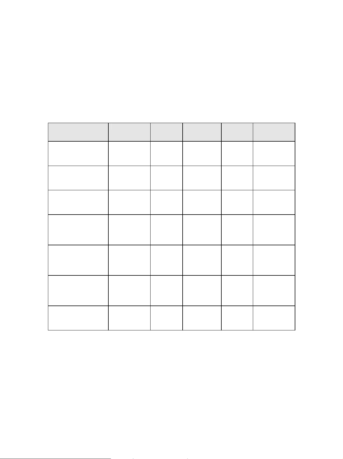
5 Finishing Support
Finishing support includes offset stacking, stapling, hole punch, center fold-in and saddle staple.
The tables below show the finishing support provided with your printer and finishing support when an
optional finisher is installed.
The Lexmark C770, C780, X644e MFP and X646e MFP do not support optional finishers.
Finishing functions for all products except Lexmark C935, X940e MFP, X945e MFP, Lexmark
X850e MFP, X852e MFP, and X854e MFP
Function/
Support with
Optional Finisher
Lexmark C772
Lexmark C782
Lexmark C920
(see Notes 2 and 3)
Lexmark T640, T642,
and T644
(see Note 1)
Lexmark W840
Lexmark X646ef MFP
(see Note 1)
Lexmark X782e MFP
Hole Punch Offset
Stacking
–
–
Finisher
Physical Bin 1
and 2
–
Finisher
Physical Bin 2
–
–
Finisher
Physical
Bin 1
Finisher
Physical
Bin 1
Finisher
Physical
Bin 2
Finisher
Physical
Bin 1
Std Bin,
Finisher
Physical
Bin 2
Finisher
Physical
Bin 1
Finisher
Physical
Bin 1
Staple
Bin
Finisher
Physical Bin
1
Finisher
Physical Bin
1
Finisher
Physical Bin
2
Finisher
Physical Bin
1
Finisher
Physical Bin
2
Finisher
Physical Bin
1
Finisher
Physical Bin
1
Staple
position
Single
(Top Left)
Single
(Top Left)
Single
(Top Left)
Single
(Top Left)
Front
Dual
Rear
Single
(Top Left)
Single
(Top Left)
Maximum
Staple Packet
Size*
25 Sheets
25 Sheets
30 Sheets
25 Sheets
50 Sheets
25 Sheets
25 Sheets
* - 20 lb. plain letter paper
– Indicates not supported.
Note 1: The Lexmark T640, T642, T644, and X646ef MFP models support several different output
devices. The optional finisher is always installed as the first output device and provides one
additional output bin.
Note 2: The Lexmark C920 finishing functions only apply to letter and A4 paper sizes. For all other sizes,
the job will print but finishing functions will not be performed.
Note 3: Paper is stacked face up in finisher physical bin 1.
51
Page 52

Finishing functions for Lexmark C935, X940e MFP, X945e MFP, Lexmark X850e MFP, X852e
MFP, and X854e MFP (Note 3).
The finishing functions do not apply to all paper sizes. When a function can not be applied to a specific
paper, the job will print but finishing functions will not be performed.
Function/
Support with
Optional
Finisher
Lexmark
C935, X940e
MFP, X945e
MFP,
Lexmark
X850e MFP,
X852e MFP,
X854e MFP
Hole
Punch
Finisher
Physical
Bin 2
Offset
Stacking
Finisher
Physical
Bin 2
Staple
Bin
Finisher
Physical
Bin 2
Staple
position
(Note 1)
Front
Rear
Dual
Double Dual
Maximum
Staple
Packet
Size*
50
Sheets
Center
Fold
(Note 2)
Finisher
Physical
Bin 3
(Advanced
Finisher
only)
Saddle
Staple
(Note 2)
Finisher
Physical
Bin 3
(Advanced
Finisher
only)
* - 20 lb. plain letter paper
– Indicates not supported.
Note 1: Letter and A4 paper must be loaded Long Edge Fed (LEF) for Double Dual stapling to be
performed.
Note 2: Two optional finisher units are supported. The Standard Finisher has two bins and does not support
Center Fold-in or Saddle staple (Saddle stitch-in). The Advanced Finisher supports all listed
finishing functions. Letter and A4 paper must be loaded Short Edge Feed (SEF) for Center fold-in
and Saddle stitch-in to be performed.
Note 3: Advanced finishing functions for the Lexmark X850e MFP, X852e MFP, and X854e MFP are
supported on base printer code LC3.BE.P339 (or greater) with IPDS code 3.01-01257 (or greater).
52
Page 53

5.1 Offset Stacking
Offset stacking of IPDS jobs is available when offset stacking is supported in the printer standard bin or
when an optional finisher with offset stacking capability is installed. For offset stacking to occur, the
following must happen:
• Host Controlled must be selected in Option Card Menu > IPDS MENU > EMULATION >
PAPER HANDLING > Offset Stacking. Host Controlled is the default value. See section
on page
• Offset stacking commands must be received with the IPDS job.
• The bin selection specified in the IPDS job must be mapped to a bin that supports offset stacking.
See
Output bin selection takes precedence over offset stacking.
Hole punching may be performed with offset stacking.
Note: The Offset Pages menu item under the printer’s Settings > Finishing Menu does not affect offset
stacking of IPDS jobs.
Note: Offset stacking is not supported for all papers sizes or types. Refer to your finisher or printer
documentation for additional information.
33 for additional information.
MAP OUTPUT BINS Menu Options on page 40 for additional information on bin mapping.
3.5.2
5.1.1 AS/400 and iSeries Offset Stacking
When offset stacking is available, the IPDS emulation reports to the host that offset stacking is supported.
The AS/400 and iSeries automatically send offset stacking commands with each job. The host default
output bin selection number is 1, which selects the printer standard bin. If the printer supports offset
stacking in the standard bin, the job will be offset.
Following are different ways to ensure that jobs are offset. The following examples assume that an
optional finisher is installed and offset stacking is supported in the finisher physical bin 1.
• Change the host output bin selection number to 2 in the default printer file using the CHGPRTF
command. (Assumes printer default bin mappings.)
• Create a new printer file using the CRTPRTF command and set the host output bin selection
number to 2. (Assumes printer default bin mappings.)
• In the printer’s Option Card Menu > IPDS MENU > MAP OUTPUT BINS menu, change Bin
Mapping 1 output bin value from Standard Bin to Bin 1. (Assumes the host output bin selection
number is 1.) This routes all jobs that would normally have gone to the printer standard bin to
finisher bin 1, which supports offset stacking. See
for details on bin mapping.
The following examples assume that an optional finisher is installed and offset stacking is supported in
the finisher physical bin 2.
• Change the host output bin selection number to 3 in the default printer file using the CHGPRTF
command. (Assumes printer default bin mappings.)
MAP OUTPUT BINS Menu Options on page 40
• Create a new printer file using the CRTPRTF command and set the host output bin selection
number to 3. (Assumes printer default bin mappings.)
• In the printer’s Option Card Menu > IPDS MENU > MAP OUTPUT BINS menu, change Bin
Mapping 1 output bin value from Standard Bin to Bin 2. (Assumes the host output bin selection
number is 1.) This routes all jobs that would normally have gone to the printer standard bin to
53
Page 54

finisher bin 2, which supports offset stacking. See
for details on bin mapping.
MAP OUTPUT BINS Menu Options on page 40
5.1.2 Mainframe Offset Stacking
For MVS JES2/JES3 offset stacking is controlled by the COPYMARK parameter contained in the printer
device definition statement in the JES2/JES3 initialization member. The following examples illustrate the
options and syntax for both JES2/JES3.
Example 1- JES2
JES2 Specifications using the COPYMARK parameter. (See note):
COPYMARK=DATASET Offset stacking increment on dataset boundary.
COPYMARK=JOB Offset stacking increment on job boundary.
COPYMARK=CONSTANT No offset stacking is performed.
Example 2 – JES3
JES3 Specifications using the COPYMARK parameter. (See note):
COPYMARK=C Offset stacking increment on dataset boundary.
COPYMARK=J Offset stacking increment on job boundary.
COPYMARK=N No offset stacking is performed.
Note: Copy marks are not generated by the IPDS emulation.
Example 3 - Output bin selection
The host default output bin selection number is 1, which selects the printer standard bin. If offset stacking
is supported in the printer standard bin, offset stacking will be performed.
Following are different ways to ensure jobs are offset. The following examples assume that an optional
finisher is installed and offset stacking is supported in the finisher physical bin 1.
• Specify OUTBIN in the JCL statements as follows:
//OUT1 OUTPUT OUTBIN=2
//DDNAME DD SYSOUT=CLASS,OUTPUT=(*,OUT1)
• Specify OUTBIN=2 in the OUTPUT DD card of your IEBGENER job.
• In the printer’s Option Card Menu > IPDS MENU > MAP OUTPUT BIN menu, change Bin
Mapping 1 output bin value from Standard Bin to Bin 1. (Assumes the host output bin selection
number is 1.) This routes all jobs that would normally have gone to the printer standard bin to
finisher bin 1, which supports offset stacking. See
for details on bin mapping.
The following examples assume that an optional finisher is installed and offset stacking is supported in
the finisher physical bin 2.
• Specify OUTBIN in the JCL statements as follows:
//OUT1 OUTPUT OUTBIN=3
//DDNAME DD SYSOUT=CLASS,OUTPUT=(*,OUT1)
MAP OUTPUT BINS Menu Options on page 40
• Specify OUTBIN=3 in the OUTPUT DD card of your IEBGENER job.
• In the printer’s Option Card Menu > IPDS MENU > MAP OUTPUT BIN menu, change Bin
Mapping 1 output bin value from Standard Bin to Bin 2. (Assumes the host output bin selection
54
Page 55

number is 1.) This routes all jobs that would normally have gone to the printer standard bin to
finisher bin 2, which supports offset stacking. See
for details on bin mapping.
MAP OUTPUT BINS Menu Options on page 40
55
Page 56

5.2 Stapling
Stapling is available when an optional finisher is installed.
When stapling is specified in the IPDS job, the job bin selection will be ignored and the job will be routed
to a bin that supports stapling.
Jobs are stapled according to the following printer and finisher restrictions. It is the user's responsibility to
load a media type and size that can be stapled by the optional finisher. Refer to your printer
documentation for media types and sizes supported by the optional finisher and for any additional
restrictions that may apply.
• Jobs that exceed the maximum staple packet size may or may not be stapled. Results will be
different for different finisher units.
• Stapling has a higher priority than output bin selection.
• Stapling and hole punch may be performed on the same job.
Note: The Staple Job menu item under the printer’s Settings > Finishing Menu does not affect stapling
of IPDS jobs.
5.2.1 AS/400 and iSeries Stapling
Stapling is controlled in the printer file parameters on the AS/400 and iSeries. Printer files may be created
using the ‘CRTPRTF’ command or changed using the ‘CHGPRTF’ command. Check to see that all PTFs
that affect stapling have been applied before calling for technical support.
Finishing capabilities for optional finishers vary. Differences are explained below.
56
Page 57

5.2.1.1 Lexmark C772, C782, C920, T640, T642, T644, X646ef MFP, and X782e MFP Optional
Finisher
The optional finisher supports only one staple position. You can not physically change the position of the
staple. The printer automatically rotates text before stapling when the finisher is installed. If necessary,
reformat your job on the host with a different text orientation to avoid stapled sets that are hard to read.
Refer to your printer or finisher documentation to determine the finishing support and staple location for
various paper sizes. Finishing functions may not be applied to all paper sizes.
Parameters in the printer file that affect stapling
Printer device type *IPDS
Output bin For Lexmark C772, C782, T640, T642, T644, X646ef MFP, and X782e MFP
use 2.
For Lexmark C920, use 3.
Corner staple
*DEVD
or *TOPLEFT
The *DEVD staple position is the top left. Specifying any other setting may cause an exception to be
reported to the host.
Drawing of staple placement
*DEVD
*TOPLEFT
Text
Text text text text
text
text.
Short-edge fed
paper, leading edge
Text shown with
0 degree
rotation
specified in
IPDS job
57
Page 58

5.2.1.2 Lexmark C935, W840, X850e MFP, X852e MFP, X854e MFP, X940e MFP, and X945e MFP
Optional Standard Finisher
The optional Standard Finisher supports Corner staple and Dual staple (IPDS Edge stitch). The printer
automatically rotates the text 180 degrees for short-edge fed paper and 90 degrees for long-edge fed
paper. If necessary, reformat your job on the host with a different text orientation to avoid stapled sets
that are hard to read.
Refer to your printer or finisher documentation to determine the finishing support and staple location for
various paper sizes. Finishing functions may not be applied to all paper sizes.
See
Lexmark C935, X940e MFP, X945e MFP, X850e MFP, X852e MFP, and X854e MFP Optional
Advanced Finisher Functions (on page
60) for information on additional functions supported.
The Printer device type must always be *IPDS.
How to specify Printer File parameters is shown below.
5.2.1.2.1 Corner Staple
Parameters in the printer file
Corner staple ………*TOPLEFT, *BOTLEFT, *TOPRIGHT or *DEVD
Drawings of staple placement
*TOPLEFT
*DEVD
*BOTLEFT
TEXT
Text
Text text text
*TOPRIGHT
*TOPLEFT
*DEVD
TEXT
Text, text. Text
xxxxx
Text is shown with 0
degree rotation
specified in IPDS job
Long-edge fed
paper, leading
edge
Text is shown with
0 degree rotation
specified in IPDS
job
Short-edge fed
paper, leading
edge
58
Page 59

5.2.1.2.2 Dual Staple (IPDS Edge stitch with 2 staples)
Parameters in the printer file
Edge stitch
Reference edge............ *LEFT, *TOP or *DEVD
Reference edge offset..... *DEVD
Number of staples......... *DEVD or 2
Staple offsets............ *DEVD
Two staples are placed on the left or top reference edge of the paper.
*TOP must only be used with short edge fed paper.
*LEFT must only be used with long edge fed paper.
An invalid staple position parameter may cause an exception to be reported to the host.
The “Reference edge offset”, “Number of staples”, and “Staple offsets” parameters are not supported, and
are ignored if set to other values.
Drawings of staple placement
*LEFT
*DEVD
*TOP
*DEVD
TEXT
Text
Text text text
Text is shown with 0
degree rotation
specified in IPDS job
Long-edge fed paper,
leading edge
Text is shown with 0
degree rotation
specified in IPDS job
Short-edge fed
paper, leading edge
TEXT
Text, text. Text
xxxxx
59
Page 60

5.2.1.3 Lexmark C935, X940e MFP, X945e MFP, X850e MFP, X852e MFP, and X854e MFP Optional
Advanced Finisher Functions
The Lexmark C935, X940e MFP, X945e MFP, X850e MFP, X852e MFP, and X854e MFP support a
Standard Finisher and an Advanced Finisher. Advanced finishing functions for the X850e MFP, X852e
MFP, and X854e MFP are supported on base printer code LC3.BE.P339 (or greater) with IPDS code
3.01-01257 (or greater). The Advanced Finisher supports Corner staple, Dual staple (IPDS Edge stitch
with 2 staples), Double Dual staple (IPDS Edge stitch with 4 staples), Center Fold (IPDS Center Fold-in),
and Saddle staple (IPDS Saddle stitch-in). The printer automatically rotates the text 180 degrees for shortedge fed paper and 90 degrees for long-edge fed paper. If necessary, reformat your job on the host with a
different text orientation to avoid stapled or folded sets that are hard to read.
Finishing functions may not be applied to all paper sizes. Refer to your printer or finisher documentation
to determine the finishing support and staple location for various paper sizes.
The Printer device type must always be *IPDS.
How to specify the Printer File parameters for Double Dual staple, Center Fold, and Saddle staple is shown
below. Examples for Corner staple and Dual staple are in section
5.2.1.2 on page 58.
60
Page 61

5.2.1.3.1 Double Dual Staple (IPDS Edge Stitch with four staples)
Double Dual staple (IPDS Edge stitch with four staples) may be controlled by the Edge stitch parameters
in the Printer File. Four staples are placed on the long edge of the paper. Double Dual staple is only
supported on Letter and A4 when the paper is loaded for Long Edge Fed (LEF) printing.
Parameters in the printer file
Edge stitch
Reference edge............ *LEFT or *DEVD
Reference edge offset..... *DEVD
Number of staples......... 4
Staple offsets............ *DEVD
Reference edge: *LEFT or *DEVD – NACKs may be generated for other parameters.
Reference edge offset: *DEVD – All other values ignored.
Number of staples - 4
Note: If the number of staples is 2, Edge stitch with two staples will be performed.
Staple Offsets: *DEVD – All other values ignored.
Drawings of positions
o
0
180
o
ABC
90
ABC
o
270
o
ABC
61
Page 62

5.2.1.3.2 Center Fold (IPDS Center Fold-in)
Center Fold-in may be specified using various application programs using the Operation Type Center
Fold-in (X'08' in the IPDS data stream).
Center Fold-in folds the paper along the centerline of the paper with the printed side folded in. Center
Fold-in is only supported on selected paper sizes. Refer to your printer or finisher documentation for the
paper sizes supported.
Center Fold-in is only supported on Letter and A4 paper when the paper is loaded for Short Edge Fed
(SEF) printing. All jobs specifying Center Fold-in will be routed to the finisher physical bin 3. Center
Fold-in has a higher priority than bin selection, offset, and hole punch. These functions will be ignored
when specified with Center Fold-in.
5.2.1.3.3 Saddle Staple (IPDS Saddle stitch-in)
Saddle staple may be specified using various application programs using the Operation Type Saddle
stitch-in (X'12' in the IPDS data stream).
Saddle stitch-in folds the paper inward (printed side in) along the centerline and places two staples in the
centerline fold. Saddle stitch-in is only supported on selected paper sizes. Refer to your printer or finisher
documentation for the paper sizes supported.
Saddle stitch-in is only supported on Letter and A4 paper when the paper is loaded for Short Edge Fed
(SEF) printing. All jobs specifying Saddle stitch-in will be routed to finisher physical bin 3. Saddle stitchin has a higher priority than bin selection, offset, and hole punch. These functions will be ignored when
specified with Saddle stitch-in.
Saddle stitch-in may be controlled by the following parameters in the Printer File
Saddle stitch-in
Reference edge............ *LEFT or *DEVD
Reference edge offset..... *DEVD
Number of staples......... *DEVD, Integer (see Number of staples below)
Staple offsets............ *DEVD
Reference edge: *LEFT or *DEVD – NACKs may be generated for other parameters.
Reference edge offset: *DEVD – All other values ignored.
Number of staples:
*DEVD – Two staples
Integer – All integer values result in two staples.
Staple offsets: *DEVD – All other values ignored.
62
Page 63

5.2.2 Mainframe Stapling
Stapling is controlled in MVS by the PSF Form Definition parameters used within the job being sent to
the printer from the host system. The form definition for stapling can be defined either in the host PSF
printer member or on the sysout statement of the job being sent.
5.2.2.1 Lexmark C772, C782, C920, T640, T642, T644, X646ef MFP, and X782e MFP Optional
Finisher
The optional finisher supports only one staple position. You can not physically change the position of the
staple. The printer automatically rotates text before stapling when the finisher is installed.
If necessary, reformat your job on the host with a different text orientation to avoid stapled sets that are
hard to read. Refer to your printer or finisher documentation to determine the staple location for various
paper sizes.
The form definition to use in the PSF printer member or in the job output statement for simplex printing
is: F1FC0010. (See PSF OS/390 Users Guide for other Form Definitions Supplied with PSF, for Staple
with Duplex, Tumble etc.)
The following is an example of a job output statement that includes the Form Definition to use IPDS
staple function for a simplex job:
//OUT1 OUTPUT CLASS=C,COPIES=1,FORMDEF=FC0010
63
Page 64

5.2.2.2 Lexmark C935, W840, X850e MFP, X852e MFP, X854e MFP, X940e MFP, and X945e MFP
Optional Standard Finisher
The optional Standard Finisher supports Corner staple and Dual staple (IPDS Edge stitch). The printer
automatically rotates the text 180 degrees for short-edge fed paper and 90 degrees for long-edge fed
paper. If necessary, reformat your job on the host with a different text orientation to avoid stapled sets
that are hard to read. Refer to your printer or finisher documentation to determine the staple location for
various paper sizes.
See
Lexmark C935, X940e MFP, X945e MFP, X850e MFP, X852e MFP, and X854e MFP Optional
Advanced Finisher Functions (on page
65) for information on additional functions supported.
Below are examples of job output statements that include the Form Definition to place staples in the
printed output.
Corner staple
//OUT1 OUTPUT CLASS=C,COPIES=1,FORMDEF=FC0010
Dual staple
//OUT1 OUTPUT CLASS=C,COPIES=1,FORMDEF=FE0010
Sending form definitions that specify invalid staple locations may cause an exception to be reported to the
host.
Drawings of staple placement for simplex form definitions
FC0010
FE0010
FE0010
TEXT
Text
Text text text
Text is shown with 0
degree rotation
specified in IPDS job
Long-edge fed paper,
leading edge
Text is shown with 0
degree rotation
specified in IPDS job
FC0010
TEXT
Text, text. Text
xxxxx
Short-edge fed
paper, leading edge
64
Page 65

5.2.2.3 Lexmark C935, X940e MFP, X945e MFP, X850e MFP, X852e MFP, and X854e MFP Optional
Advanced Finisher Functions
The Lexmark C935, X940e MFP, X945e MFP, X850e MFP, X852e MFP, and X854e MFP support a
Standard Finisher and an Advanced Finisher. Advanced finishing functions for the Lexmark X850e MFP,
X852e MFP, and X854e MFP are supported on base printer code LC3.BE.P339 (or greater) with IPDS
code 3.01-01257 (or greater). The Advanced Finisher supports Dual staple (IPDS Edge stitch), Double
Dual staple (IPDS Edge stitch with 4 staples), Center Fold (Center Fold-in), and Saddle staple (Saddle
stitch-in). The printer automatically rotates the text 180 degrees for short-edge fed paper and 90 degrees
for long-edge fed paper. If necessary, reformat your job on the host with a different text orientation to
avoid stapled or folded sets that are hard to read.
Finishing functions may not be applied to all paper sizes. Refer to your printer or finisher documentation
to determine the finishing support and staple location for various paper sizes
How to specify the Printer File parameters for Saddle staple is shown below. Examples for Corner staple
and Dual staple are in section
5.2.2.3.1 Saddle Staple (IPDS Saddle stitch-in)
5.2.2.2 on page 64.
Saddle staple may be specified using various application programs using the Operation Type Saddle
stitch-in (X'12' in the IPDS data stream).
Saddle stitch-in folds the paper inward (printed side in) along the centerline and places two staples in the
centerline fold. Saddle stitch-in is only supported on selected paper sizes. Refer to your printer or finisher
documentation for the paper sizes supported.
Saddle stitch-in is only supported on Letter and A4 paper when the paper is loaded for Short Edge Fed
(SEF) printing. All jobs specifying Saddle stitch-in will be routed to finisher physical bin 3. Saddle stitchin has a higher priority than bin selection, offset, and hole punch. These functions will be ignored when
specified with Saddle stitch-in.
The following is an example of a job output statement that includes the Form Definition to perform
Saddle stitch-in.
//OUT1 OUTPUT CLASS=C,COPIES=1,FORMDEF=FS0010
65
Page 66

5.3 Hole Punching
Hole punching of IPDS jobs is available when an optional finisher with hole punch capability is installed.
See the table on page
A job may select hole punch by specifying it in an IPDS command. When hole punch is selected through
an IPDS data stream command, hole punch will override output bin selection and the job will be routed to
a bin that supports hole punch.
The following is an example of a job output statement that includes the Form Definition to perform 3-hole
punch.
//OUT1 OUTPUT CLASS=C,COPIES=1,FORMDEF=F1H10110
Pages may also be hole punched by selecting a value in the printer’s Option Card Menu > IPDS MENU
> MAP INPUT TRAYS menu or in the printer’s Option Card Menu > IPDS MENU > MAP
OUTPUT BINS menu. When this method is used, the hole punch command does not have to be received
in the job. Refer to your printer or finisher documentation to determine the hole punch location for
various paper sizes. The following sections describe how to use the printer menus to hole punch IPDS
jobs.
Note: The Hole Punch menu item under the printer’s Settings > Finishing Menu does not affect hole
punching of IPDS jobs.
51 to determine if your finisher supports hole punching.
5.3.1 Hole Punching From an Input Source
Hole punching may be performed on paper pulled from any paper input source on the printer. Hole
punching from an input source is specified using the printer’s Option Card Menu > IPDS MENU >
MAP INPUT TRAYS menu. See
information. A combination of the printer physical input source and the IPDS data stream requested input
source is used to specify hole punching.
Example 1 - To have all pages
To have all pages
INPUT TRAYS menu:
1. Select Tray Mapping 1
2. Select Tray 1Hp
3. Select IPDS Number 0
This sets Tray Mapping 1 to Tray 1Hp to IPDS Number 0. When the IPDS input source 0 is specified in
the data stream, paper is picked from the printer physical Tray 1 and hole punched.
Example 2 - To have selected pages
example.)
To have some pages punched and some pages not punched
MENU > MAP INPUT TRAY menu:
Tray Mapping 1 to Tray 1 to IPDS Number 0 (Default Setting)
(When IPDS Number 0 is the requested source in the IPDS data stream, pages are pulled from the printer
physical Tray 1 and are not hole punched. 0 is the IPDS default input source value.)
printed from the printer physical Tray 1 hole punched, specify the following in the MAP
MAP INPUT TRAYS Menu Options on page 37 for additional
from Tray 1 hole punched (Default settings are assumed in this example)
from Tray 1 hole punched (Default settings are assumed in this
from Tray 1, specify the following in the IPDS
66
Page 67

Tray Mapping 8 to Tray 1 Hp to IPDS Number 4.
(When IPDS Number 4 is the requested source in the IPDS data stream, pages are pulled from the printer
physical Tray 1 and all pages are hole punched.)
5.3.2 Hole Punching to an Output Bin
Hole punching may be performed on paper routed to any optional finisher output bin. Hole punching to
an output bin is specified using the printer’s Option Card Menu > IPDS MENU > MAP OUTPUT
BINS menu. See
combination of the printer physical output bin and the IPDS data stream specified output bin is used to
specify hole punching.
Example 1 - To have all pages
example. Check the finishing support table on page
To have all pages
MAP OUTPUT BINS menu:
Finisher Physical Bin 1 Finisher Physical Bin 2
1. Select Bin Mapping 1 1. Select Bin Mapping 1
2. Select Output Bin 1 Hp 2. Select Output Bin 2 Hp
3. Select IPDS Number 1 3. Select IPDS Number 1
When the requested output bin number is 1 in the IPDS data stream, pages are hole punched and stacked in
the finisher physical output bin selected.
Example 2 - To have selected pages
in this example. Check the finishing support table on page
punch.)
To have some pages punched and some pages not punched
output bin, specify the following in the IPDS MENU > MAP OUTPUT BINS menu:
Finisher Physical Bin 1 Finisher Physical Bin 2
MAP OUTPUT BINS Menu Options on page 40 for additional information. A
stacked in a finisher bin hole punched (Default settings are assumed in this
51 to determine the bins that support hole punch.)
stacked in an output bin hole punched, specify the following in the IPDS MENU >
stacked in an output bin hole punched (Default settings are assumed
51 to determine the bins that support hole
as they are stacked in the finisher physical
1. Select Bin Mapping 1 1. Select Bin Mapping 1
2. Select Output Bin 1 2. Select Output Bin 2
3. Select IPDS Number 1 3. Select IPDS Number 1
4. Select Bin Mapping 4 4. Select Bin Mapping 4
5. Select Output Bin 1 Hp 5. Select Output Bin 2 Hp
6. Select IPDS Number 2 6. Select IPDS Number 2
Note: IPDS Number 1 is the default IPDS data stream output bin.
When IPDS Number 1 is the requested output bin in the IPDS data stream, pages are stacked in the
finisher physical output bin and are not hole punched.
When IPDS Number 2 is the requested output bin in the IPDS data stream, pages are stacked in the
finisher physical output bin and are hole punched.
67
Page 68

6 IPDS Job Cancel
6.1 Canceling IPDS Jobs
IPDS jobs may be cancelled using the normal cancel sequence for the printer.
Cancel Job while an IPDS job is being processed causes an “IPDS cancel exception” to be sent to the
host. The host responds by placing the first non-completed IPDS job in a held status and sending the
remaining jobs on the queue.
IPDS resources are saved by the printer unless the host requests deletion of these resources.
Selecting a specific job to cancel can be difficult when several small jobs are queued to print from the
host.
6.2 How to Cancel a Job Using the Printer Operator Panel
1. Press the Select button on the operator panel while your IPDS job is printing.
BUSY
9 Cancel Job
Status / Supplies
Held Jobs
2. The printer will clear the paper path and display a Stopping message.
Stopping ….
3. Only one Print Job will be shown in the next menu. Press
Select to cancel
.
9 Print Job xxxxxxxx
To continue printing without canceling the job, press the Back button .
4. The printer will automatically return to its normal state, which will be BUSY if it is in the process
of printing other jobs.
Cancelling Print Job xxxxxxxx
68
Page 69

6.3 How to Cancel a Job Using the MFP Touch Screen
1. While any job is printing, the Cancel Job icon will be displayed on the control panel. Touch the
icon.
2. In the “Print” column, select the job you want to cancel by touching the print job icon.
3. Touch the Delete Selected Job icon.
4. The screen will display a message to indicate that the job is being deleted.
5. The screen will return to the Home display.
69
Page 70

7 Working with Captured Fonts
7.1 Capture Font and Remove Font
Capture is a function whereby downloaded fonts can be stored on disk or user flash. The flash memory
and hard disk may be printer optional storage media ordered separately from the printer.
Menu path: Option Card Menu > IPDS MENU > FONT CAPTURE. This menu group has two items:
Capture Fonts and Remove Fonts.
These menu items are described in
A captured font is treated as if it is a printer-resident font. Unlike resident fonts, which can not be deleted,
captured fonts may be deleted when storage space is required. Fonts that are resident on the printer will
not be downloaded for capture by the host.
Captured fonts are:
• only available to the IPDS emulation.
• retained in the printer across job boundaries, IPDS sessions and power cycles.
• available for use by any host connected to the printer.
Fonts captured to flash memory or a disk remain in the printer until:
• cleared by using the Remove Fonts menu item or
• overwritten with a later capture of a font with the same object ID or characteristics
Fonts activated from flash or disk and in use during a session will not be cleared by Remove Fonts.
Activated fonts will remain in memory until the activation is removed by the host or the session with the
host is ended.
When there is not enough space remaining to capture a font, a message will be displayed. Select
Continue on the operator panel or touch screen to clear the message. Some printers may automatically
continue after a short period of time. The job will be printed without capturing any remaining fonts. Only
one such message is displayed during an IPDS session. This prevents the printer from halting each time a
new font is received.
FONT CAPTURE Menu Options on page 49.
7.2 Preparing Fonts for Capture
Fonts that can be captured are: eligible bitmap fonts (LF1 format), eligible outline fonts (LF3 format), and
eligible TrueType fonts. TrueType fonts can only be captured to disk.
The resolution of the captured font must match the IPDS emulation resolution for the font to be used by
the host application. For instance, a font captured with a 300 pel resolution can not be used by the IPDS
emulation when it is emulating an IBM 3812/3816 printer. The fonts used in emulating a 3812/3816
printer have a resolution of 240 pels.
Important: Fonts intended for capturing must be marked eligible for capture on the host before they
will be downloaded to the printer for capture. You should always check your font licensing information
before making a font eligible for capture. Sensitive fonts should not be made eligible for capture.
Basic information about how mark a font as eligible on the AS/400 or iSeries is on page
information about how to mark a fonts as eligible on a Mainframe is on page
70
72.
71. Basic
Page 71

7.2.1 Capturing Fonts from an AS/400 or iSeries
7.2.1.1 Program Requirements
On an AS/400, PSF/400 V4R2 or later is required for making fonts eligible for capture. All iSeries
releases support font capture.
7.2.1.2 Making Fonts Eligible for Capture on the Host
Two steps are required to capture fonts. These are:
1. Make the font resource eligible for capture.
To mark a font resource eligible for capture, set FNTCAPTURE to *YES. This is done when you create
the font resource using the CRTFNTRSC command or change the font resource using the CHGFNTRSC
command. A raster font is built from a font character set and a code page. Both of these font resources
must be marked eligible for the raster font to be captured. Additional information on font capture may be
found in iSeries Printer Device Programming Version 5 (SC41-5713-04).
2. Identify the printer as being capable of capturing fonts.
Set the FNTCAPTURE parameter to *YES in the printer PSFCONFIG.
Note: If you need to make TrueType fonts eligible for capture, you should probably use the Font
Installer for AFP Systems.
71
Page 72

7.2.2 Capturing Fonts from a Mainframe Host
7.2.2.1 Mainframe Program Requirements
Font capture is supported by PSF/MVS 2.2.0 with APAR OW08340 and PSF/VSE 2.2.1 with APAR
DY43969.
7.2.2.2 Making Fonts Eligible for Capture on a Mainframe
Note: The procedures/documentation below are for OS390/MVS/PSF platform. The following are the
software release requirements for font capture feature within this platform. (For details on font
capture with PSF refer to the PSF Customization Guide, Program Number: 5655-B17)
OS390/MVS 2.4 or later
PFS for MVS 2.2 or later
Note: Earlier releases may also support "Font Capture". For details - check your "PSF Customization
Guide".
There are basically 3 steps involved regarding font capture as follows:
1. Display current font marking status.
2. Mark fonts for capture.
3. Send job from host to printer with the font and font character set you want printer to capture.
Fonts on the host can be marked either "PUBLIC", "PRIVATE", or "UNMARKED". In order for the
printer to capture fonts as resident the fonts must be marked "PUBLIC" on the host. Fonts marked
"PRIVATE" are only temporarily downloaded and are removed from printer by the host. "UNMARKED"
fonts are treated the same as if they were marked "PRIVATE" and will not be captured as printer resident
fonts.
Detailed examples of the three steps are shown below.
Note: If you need to make TrueType fonts eligible for capture, you should probably use the Font
Installer for AFP Systems.
72
Page 73

STEP 1. DISPLAY CURRENT FONT MARKING STATUS
To determine the marking status of your host fonts you can run the APSRMARK report utility. The
following is a sample of the JCL to run the font report listing.
Sample JCL to run font report listing to determine current font marking status:
//APSHORT JOB (),
// CLASS=A,
// MSGCLASS=A,
// MSGLEVEL=(1,1),
// NOTIFY=&SYSUID,
// TIME=1440
//*** NOTE: USE THIS JOB TO PRINT SHORT FONT STATUS MARKINGS ONLY ****
//*** NOTE: CHANGE DSN LINE 13 (IN1 STATEMENT) TO MATCH YOUR FONTLIB *
//********************************************************************
//STEP1 EXEC PGM=APSRMARK
//SYSPRINT DD SYSOUT=J
//*
//IN1 DD UNIT=3390,DSN=SYS1.FONTLIBB,DISP=SHR,VOL=SER=OS3R7A
//SYSIN DD *
INDD=IN1,MEMBER=ALL,REPORT,SHORT
/*
Note: Change report type to "LONG" for font detailed report (replace the "SHORT" option).
STEP 2. MARKING FONTS FOR CAPTURE
In order for printer to capture host fonts as resident printer fonts they must be marked "PUBLIC". The
following is a sample of the JCL commands to mark existing fonts as "PUBLIC".
Sample JCL to Mark Fonts "PUBLIC":
//APSMARK JOB (),
// CLASS=A,
// MSGCLASS=A,
// MSGLEVEL=(1,1),
// NOTIFY=&SYSUID,
// TIME=1440
//*********************************************************************
//* THIS JOB WILL MARK FONTS FOR CAPTURE FOR PRINTER FROM FONT LIB. *
//* MARK THEM AS EITHER PUBLIC OR PRIVATE. TO MARK PUBLIC ENTER *
//* "PUBLIC" KEYWORD ON LINE 18 INDD STATEMENT. FOR PRIVATE ENTER *
//* "PRIVATE" KEYWORD ON LINE 18 INDD STATEMENT. THEN SUBMIT. *
//* TO DISPLAY STATUS MARKING CHANGE RUN REPORT JOB "APSSHORT". *
//*********************************************************************
//* NOTE: USE "REPLACE" IF MEMBER ALREADY EXIST: SEE FOLLOWING EXAMPLE*
//* NOTE: USE "REPLACE" IF MEMBER ALREADY EXIST: SEE FOLLOWING EXAMPLE*
//* INDD=IN1,OUTDD=OUT1,MEMBER=C0H20000,PUBLIC,REPLACE *
//*********************************************************************
//* NOTE: BEFORE YOU RUN THIS JOB YOU MUST ALLOCATE NEW FONTLIB DSN *
//* 1ST CREATE NEW LIB, THEN USE IEBGENER TO COPY FROM OLD LIB *
//* I.E. SYS1.FONTLIBB TO NEW LIB SYS1.FONTPRIV OR SYS1.FONTPUB *
73
Page 74

//*********************************************************************
//STEP1 EXEC PGM=APSRMARK
//SYSPRINT DD SYSOUT=J
//*
//IN1 DD UNIT=3390,DSN=SYS1.FONT300,DISP=SHR,VOL=SER=OS3R7A
//OUT1 DD UNIT=3390,DSN=SYS1.FONTNEW,DISP=SHR,VOL=SER=OS3R7A
//SYSIN DD *
INDD=IN1,OUTDD=OUT1,MEMBER=T1V10037,PUBLIC
INDD=IN1,OUTDD=OUT1,MEMBER=C08400B0,PUBLIC
/*
Note: If you want to mark all fonts in a particular font library "PUBLIC" you can create a new font
library, copy, and mark all fonts as "PUBLIC" at the same time. The following is a sample of the
JCL commands to copy and mark all fonts "PUBLIC" to a new library.
Sample JCL to copy and mark all fonts "PUBLIC" to a new font library:
//APSRMARK JOB (),
// CLASS=A,
// MSGCLASS=A,
// MSGLEVEL=(1,1),
// NOTIFY=&SYSUID,
// TIME=1440
//*******************************************************************
//* THIS JOB WILL COPY/MOVE MEMBERS TO ALTERNATE FONT LIB AND *
//* MARK THEM AS EITHER PUBLIC OR PRIVATE. TO MARK PUBLIC ENTER *
//* "PUBLIC" KEYWORD ON LINE 18 INDD STATEMENT. FOR PRIVATE ENTER *
//* "PRIVATE" KEYWORD ON LINE 18 INDD STATEMENT. THEN SUBMIT. *
//* TO DISPLAY STATUS MARKING CHANGE RUN REPORT JOB "APSSHORT". *
//* *****************************************************************
//* NOTE: BEFORE YOU
RUN THIS JOB YOU MUST ALLOCATE NEW FONTLIB DSN *
//* 1ST CREATE NEW LIB, THEN USE IEBGENER TO COPY FROM OLD LIB *
//* I.E. SYS1.FONTLIBB TO NEW LIB SYS1.FONTPRIV OR SYS1.FONTPUB *
//*******************************************************************
//STEP1 EXEC PGM=APSRMARK
//SYSPRINT DD SYSOUT=J
//*
//IN1 DD UNIT=3390,DSN=SYS1.FONTLIBB,DISP=SHR,VOL=SER=OS3R7A
//INOUT1 DD UNIT=3390,DSN=SYS1.FONTPRIV,DISP=SHR,VOL=SER=OS3R7A
//SYSIN DD *
INDD=IN1,OUTDD=INOUT1,PUBLIC,MEMBER=ALL
/*
STEP 3. SENDING JOB FROM HOST TO PRINTER SELECTING FONT CHARACTER SET
YOU WANT PRINTER TO CAPTURE
Once you have marked fonts "PUBLIC" you can select the font character set to be captured from either
within printer definition member in PSF or from within the in-stream JCL of the job. The following is an
example of both.
To select font capture from printer definition member, add the "CHARS" option as follows to your PSF
printer member.
// CHARS=(88FB) /* default font set */
74
Page 75

To select font capture from in-stream JCL add the "CHARS" option to sysout/output statement as follows.
//OUT1 OUTPUT CLASS=A,
DEST=LOCAL,FORMDEF=A10110,PAGEDEF=A06462,CHARS=88FB
To print a list of captured fonts, select Print IPDS Fonts from Option Card Menu > IPDS MENU >
EMULATION (see page
30).
75
Page 76

8 Remote Configuration of Printer IPDS Settings
8.1 Why Use a Browser
Most IPDS emulation settings stored in the printer (the default IPDS settings) can be changed remotely
using a browser. This method of changing settings is especially useful during printer installation to set all
of the IPDS options to the values recommended by your system administrator. At a later time, any
necessary changes can be made on each printer, either from a browser or via the operator panel.
Using the browser, you can save new settings to a printer. Option changes will become active when the
next IPDS host session starts.
It is not possible to do everything from the browser that you can do from the operator panel; see section
8.3 on page 77.
Finally, using a browser can also be useful to display selected information about IPDS Configuration
and IPDS Product Information. This can be used as an alternative or supplement to printing menu
settings (as shown in
Page (MFPs) on page
Printing the Menu Settings Page (printers) on page 15 or Printing the Menu Settings
18).
8.2 Remote Configuration Using a Browser
A browser, such as Microsoft Internet Explorer or Netscape, may be used to remotely configure most
IPDS settings on printers attached to a LAN using a Standard Network port or MarkNet internal print
servers.
To access and change IPDS option settings through your browser:
1. End all IPDS sessions with the printer. This may involve ending all active AS/400 or iSeries
writers and draining all active Mainframe printers. (see Note)
2. Access the printer web page by typing the IP address of the printer as the URL.
3. Select Configuration.
4. Select IPDS Settings.
5. Select IPDS Configuration. All option values that may be changed remotely will be displayed.
In addition, the IPDS Version and the setting for Trace Functions will be displayed (read only).
6. Change option settings as desired.
7. Click Submit at the bottom of the page. The Submit button sends the new values to the printer.
These values are saved in the printer and will become active when the next IPDS host session is
started.
8. The browser GUI will then display a confirmation that the settings have been submitted and
return to the IPDS Configuration page, displaying the submitted values.
9. Restart all IPDS sessions. Option changes will become active when the next IPDS host session
starts.
Note: If new values are submitted during an IPDS session, the new settings will not be used until the
current IPDS session ends and a new IPDS session is established.
76
Page 77

Beside the Submit button you will see a Reset Form button. If you have entered values in the page
without submitting, and decide to start all over again, click Reset Form. The page will then display the
values that were current when you opened the IPDS Configuration page.
8.3 Functions that Can Not be Operated Remotely
The following IPDS functions can not be operated remotely:
• Trace Functions – The current setting is shown but can not be changed.
• Print IPDS Fonts – This operation is not shown.
• Remove Fonts – This operation is not shown.
• IPDS Version – The current version is shown but can not be changed.
To enable or disable Trace Functions, or to Print IPDS Fonts, use the operator panel Option Card Menu
> IPDS MENU > EMULATION > Trace Functions.
To remove captured fonts, use the printer’s Option Card Menu > IPDS MENU > Font Capture >
Remove Fonts > Yes.
77
Page 78

9 Printer Messages and Problems
Please refer to the IPDS Printer and Host Setup Guide for information on various problems and solutions.
78
Page 79
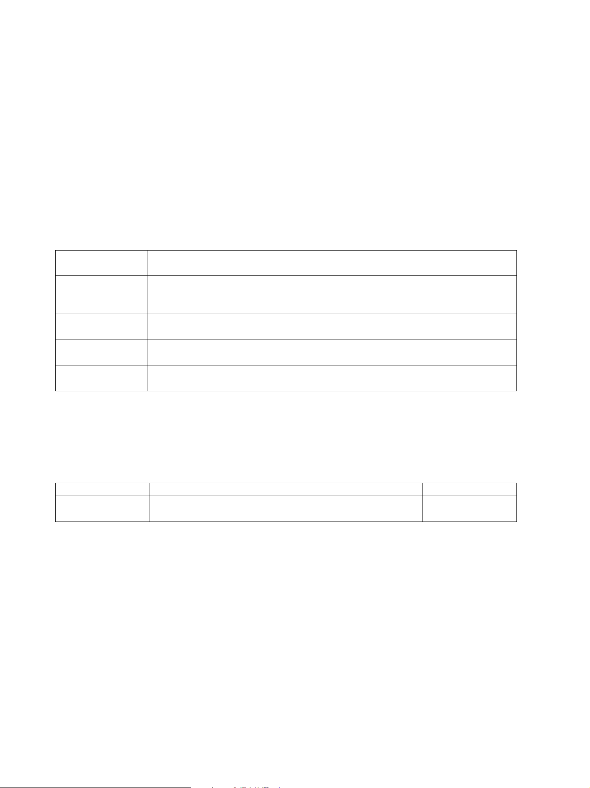
10 Command Reference
10.1 XOA Print Quality Control
Monochrome printers support the Execute Order Any State (XOA) Print Quality Control command. This
command specifies the print quality at which jobs will be printed on monochrome printers. Specifying
lower print quality levels can save toner. Color printers ignore the Print Quality Control command when it
is received. The following table gives the Quality Level value range.
The Toner Saver option in the IPDS MENU affects the processing of this command. See
23 for more information.
page
Print Quality Control Quality Level Values
Quality Level
(Byte 2 Value)
X’01’ – X’55’ Lowest print quality. Best toner saving. These quality level settings correspond to
X’56’ – X’AA’ Use the operator panel value specified in the printer menu’s Toner Darkness
X’AB’ – X’FE’ Factory default setting. Yields the best print quality with no toner saving. Check
X’FF’ Use the operator panel value specified in the printer menu’s Toner Darkness
The last print quality setting is saved across sessions when the printer and host settings are set correctly to
allow resources to be saved in the printer.
The following Negative Acknowledgment is returned by printers that support the XOA Print Quality
Control command.
Exception Description Action Code
X’0292..02’ Invalid XOA Print Quality Control parameter. An invalid
Description
setting the printer menu’s Toner Darkness option to a value of one (in Settings
> Quality Menu).
option (in Settings > Quality Menu ).
your printer documentation to determine the factory default value.
option (in Settings > Quality Menu).
quality level value of X’00’ was received.
Toner Saver on
X’01’
79
Page 80

10.2 XOH OPC Product Identifier Self Defining Field
The XOH OPC Product Identifier Self Defining field is returned to the host. This information may be
useful in locating the printer for maintenance or inventory purposes. The following table specifies the
values returned.
Product Identifier Self Defining Field Values: Bytes 0-6
Special Data
Area
Bytes 0-1 X’004C’ Length of this Self Defining field
Bytes 2-3 X’0013’ Product Identifier Self Defining Field ID
Byte 4 X’39’ Length of Self Defining Product ID Parameter
Bytes 5-6 X’0001’ Unique Product Identifier Parameter ID
Product Identifier Self Defining Field Values: Bytes 7-12
Special Data
Area
Bytes 7-12 X’F0F0F5F0F6F1’
Product Identifier Self Defining Field Values: Bytes 13-63
Special Data
Area
Bytes 13-15 X’404040’
Bytes 16-18 X’D3E7D2’ Manufacturer
Bytes 19-20 X’0000’ Plant
Bytes 21-32 12 Hex Bytes Sequence Number
Bytes 33-34 X’0000’ Tag
Bytes 35-43 9 Hex Bytes EC Level. IPDS Code Level in following form:
Bytes 44-60 17 Hex Bytes Device Specific Information
Byte 61 X’0F’ Length of Self Defining Product ID Parameter
Bytes 62-63 X’0003’ Printer Name Parameter ID
Value
Value
X’F0F0F5F0F5F6’
X’F0F0F5F0F5F7’
X’F0F0F4F0F6F1’
X’F0F0F4F0F2F4’
X’F0F0F7F0F0F2’
X’F0F0F7F5F0F0’
X’F0F0F7F5F1F0’
Value
Description for
005061
005056
005057
004061
004024
007002
007500
007510
Lexmark C770, C772, C780, C782, and X782e MFP
Lexmark C920
Lexmark C935
Lexmark T640, T642, T644, and X646ef MFP
Lexmark W840
Lexmark X644e MFP and X646e MFP
Lexmark X850e MFP, X852e MFP, and X854e MFP
Lexmark X940e MFP and X945e MFP
Description
Description
Model Number
Specific model numbers are not returned
LXK for Lexmark
Printer Serial Number
xxxxyyyyy
Printer Base Code Level in following form:
Base Code aa.bb.cccc
80
Page 81

Product Identifier Self Defining Field Values: Bytes 64 -
Area Value Description
Bytes 64-75
or 64 - 81
X'D385A79481999240C3F7F7F0' Lexmark C770
X'D385A79481999240C3F7F7F2' Lexmark C772
X'D385A79481999240C3F7F8F0' Lexmark C780
X'D385A79481999240C3F7F8F2' Lexmark C782
X'D385A79481999240C3F9F2F0' Lexmark C920
X'D385A79481999240C3F9F3F5' Lexmark C935
X’D385A79481999240E3F6F4F0’ Lexmark T640
X’D385A79481999240E3F6F4F2’ Lexmark T642
X’D385A79481999240E3F6F4F4’ Lexmark T644 and X646ef MFP
X’D385A79481999240E6F8F4F0’ Lexmark W840
X'D385A79481999240E7F6F4F48540D4C6D7' Lexmark X644e MFP
X'D385A79481999240E7F6F4F68540D4C6D7' Lexmark X646e MFP
X'D385A79481999240E7F7F8F28540D4C6D7' Lexmark X782e MFP
X'D385A79481999240E7F8F5F08540D4C6D7' Lexmark X850e MFP
X'D385A79481999240E7F8F5F28540D4C6D7' Lexmark X852e MFP
X'D385A79481999240E7F8F5F48540D4C6D7' Lexmark X854e MFP
X'D385A79481999240E7F9F4F08540D4C6D7' Lexmark X940e MFP
X'D385A79481999240E7F9F4F58540D4C6D7' Lexmark X945e MFP
10.3 Finishing Operations Self-Defining Field
Finishing operations are supported when an optional finisher is installed and the functions are supported by
the finisher. Finishing operations are reported in the Finishing Operations Self-Defining Field.The values
below are reported to the host when the finishing function is supported by the finisher.
Table 1: Finishing Operations Self-Defining Field
Bytes Description Values: Optional Finisher
Supporting
0 - 1 Length of this self-defining field, including this field X’004’ to X’008’
2 – 3 Finishing operation self-defining field ID X’0018’
4 – 7 Operation Type X’01’: Corner staple
X’03’: Edge stitch
X’08’: Center fold-in
X’12’: Saddle stitch-in
10.4 N-up Printing
N-up print support allows multiple pages to be printed on a single sheet. N-up allows 1-4 partitions to be
defined per side of a sheet of paper. This allows up to 8 pages to be printed per sheet. Default page
placement (N-up) and explicit page placement (N-up EPP) are supported. Refer to the “Load Copy
Control and Logical Page Position” command in the Intelligent Printer Data Stream Reference (S544-
3417) for more information.
81
Page 82

10.5 Color and Simulated Grey Scale Printing
Color or simulated grey scale printing is supported in all IPDS towers. Function Sets (FS) 10, 11, 42, and
45 are supported. Full process color is supported when using FS45. ABIC (Bi-level Q-Coder)
compression is not supported. Additional information may be found in the “Image Object Content
Architecture (IOCA) Reference” (publication SC31-6805-05).
Full process color using FS45 is supported on iSeries V5R2 and higher.
10.6 TrueType Fonts
TrueType fonts may be downloaded from the host. True Type Font support is only available on selected
products that support IPDS code release 3.01-01210 and higher. For some products this code may only be
available as a field upgrade. Contact your point-of-purchase for information.
TrueType fonts can be linked to a TrueType base font to form an ordered list of fonts that are essentially
processed as a single font. IPDS supports printing of linked fonts. The font linking function fulfills two
primary requirements:
• Supports the ability to add user-defined characters to a given font. This requirement is particularly
strong in Japanese, Simplified Chinese, and Traditional Chinese markets.
• Supports the ability to extend a font with additional characters. These are not user-defined characters,
but characters that did not fit into a single font due to the 64K restriction for TrueType fonts. The most
important example for this requirement is the extension of the base Chinese character set for GB18030
support.
For more information about installing and managing TrueType Fonts, consult Chapter 4 in “Using
OpenType Fonts in an AFP System” (G544-5876). For detailed information, please consult the product
documentation for the Font Installer for AFP Systems.
10.7 Object Container Support
Object container support is only available on selected products that support IPDS code release 3.01-01210
and higher. For some products this code may only be available as a field upgrade. Contact your point-ofpurchase for information.
Support for object containers makes it possible to send various types of resource and presentation objects
to the printer.
Support is currently provided for:
• TrueType fonts (see page
• JFIF (jpeg) – presentation object
• IOCA tiles (used in IO images)
82)
10.8 IO Images as Resources
Support for IO images as resources is only available on selected products that support IPDS code release
3.01-01210 and higher. For some products this code may only be available as a field upgrade. Contact
your point-of-purchase for information.
Support is given for the use of IO images as resources that can be included in a page at a later time without
having to include the IO image in an overlay.
82
Page 83

10.9 Media Reporting by Object ID (OID)
Media names identified as media IDs are returned to the host for each printer paper source. This
information is reported in Bytes 24-36 of the Execute Order Home State (XOH) Obtain Printer
Characteristics (OPC) Printable Area Self Defining Field (SDF). The tables below define the values
reported to the host.
The printer supports multiple input sources. A Printable Area SDF is returned for each input source in a
single XOH-OPC Acknowledgement Reply. The printer only reports media names for media sizes
supported by the printer input sources.
Below are tables showing common information returned in the replay and specific media IDs returned
sorted by media names.
Additional information may be found in the Mixed Object Content Architecture Reference version 5
(SC31-6802-05).
Table 1: Common Information Returned in the Reply
Special Data Area Value Returned Description
Bytes 24-25 X’000C’
X’000D’
Byte 26
X’10’
Byte 27 X’06’ OID Encoding
Byte 28 X’08’ OID Length: Double OID Byte
Bytes 29-34 X’2B1200040301’ Input Media ID common bytes
Bytes 35-36 X’bbbb’ One or two bytes representing the specific
Table 2: Specific Media IDs Returned Sorted By Media Names
Single Byte OID
Double Byte OID
Input Media ID Type
MODCA Input Media Type OID
Media ID. Values for specific media IDs (bb
or bbbb) are found in the following table.
Media Name
(Note 1)
BSNS ENV North American business envelope (9
COM 10 ENV Com 10 envelope (9.5 x 4.125 in.) 75 X’4B’ 2
C5 ENV C5 envelope (229 x 162 mm) 79 X’4F’ 2
DL ENV DL envelope (220 x 110 mm) 77 X’4D’ 2
EXEC North American executive (7.25 x 10.5
ISO A3 ISO A3 white (297 x 420 mm) 10 X’0A’
ISO A3 CO ISO A3 colored 11 X’0B’ 3
ISO A4 ISO A4 white (210 x 297 mm) 0 X’00’
ISO A4 CO ISO A4 colored 1 X’01’ 3
ISO A4 TR ISO A4 transparent 2 X’02’ 4
ISO A5 ISO A5 white (148.5 x 210 mm) 20 X’14’
ISO A5 CO ISO A5 colored 21 X’15’ 3
ISO B5 ENV ISO B5 envelope 73 X’49’ 2
Media Type ID Media type OID
(Value for ‘bb’ or ‘bbbb’
in table above)
143 X’810F’ 2
Envelope)
65 X’41’
in.)
Note
83
Page 84

Media Name
(Note 1)
JIS B4 JIS B4 (257 x 364 mm) 42 X’2A’
JIS B5 JIS B5 (182 x 257 mm) 43 X’2B’
LEDGER North American ledger (11 x 17 in) 69 X’45’
LEGAL North American legal white (8.5 x 14 in.) 60 X’3C’
LEGAL CO North American legal colored 61 X’3D’ 3
LEGAL 13 North American legal 13 (Folio) 8.5 x 13
LETTER North American letter white (8.5 x 11
LETTER CO North American letter colored 51 X’33’ 3
LETTER TR North American letter transparent 52 X’34’ 4
MON ENV Monarch envelope (7.5 x 3.875 in) 76 X’4C’ 2
STATEMNT North American statement (5.5 x 8.5 in.) 69 X’45’
Notes:
1) The paper size and paper type in the printer’s Paper Menu > Paper Size/Type option must be set
to match the media loaded in the tray. If these do not match the media loaded in the tray, incorrect
media type information will be returned to the host.
2) Media type must be set to envelope in the printer’s Paper Menu > Paper Size/Type option and
the media size must be set to the correct envelope size in Size option.
3) Media type must be set to Colored Paper in the printer’s Paper Menu > Paper Size/Type option.
If the media type is not set to Colored Paper, the OID for the white media type will be returned.
4) Media type must be set to Transparency in the printer’s Paper Menu > Paper Size/Type option.
If the media type is not set to Transparency, the OID for the white media type will be returned.
When paper is loaded in the tray or feeder and a Paper Type of Card Stock, Labels, Bond, Letterhead,
Preprinted, and Custom Type 1-6 is selected, a media ID is not returned to the host. When the Paper Size
in the printer paper menu is set to an envelope size, the Paper Type is ignored and a media ID is returned
for the envelope size selected in the Paper Size option.
Media Type ID Media type OID
(Value for ‘bb’ or ‘bbbb’
in table above)
63 X’3F’
in.)
50 X’32’
in.)
Note
84
Page 85

11 Warranty
The limited warranty you received with your printer gives warranty terms and conditions. For warranty
information, refer to your printer documentation.
85
Page 86

Appendices……………………………………..
86
Page 87

A. Technical Specifications
A.1 Product Description
The Card for IPDS and SCS/TNe is an option that is installed in the printer optional firmware card
connector. With the Card and either the Standard Network port, a MarkNet internal LAN print server, or
the Coax/Twinax Adapter for SCS, the printer becomes an IBM host workstation printer capable of
printing AFP or IPDS documents from an AS/400, iSeries, System/390, or zSeries computer.
See the SCS/TNe Emulation User's Guide for SCS printing capabilities over a LAN network connection.
The IPDS emulation supports scalable fonts and higher print resolutions. The default print resolution is
selected through an Option Card Menu >IPDS MENU setting.
The printer can be configured to take advantage of additional RAM memory. When attached to a LAN
through an internal print server, it can save IPDS resources to improve performance for complex IPDS
print jobs.
The IPDS emulation supports the IPDS data and resource towers. Fonts and other resources can be
downloaded to the printer.
If your printer supports a duplex option, duplex printing is supported for all printer emulations dependent
on host software. Up to five input sources are supported through Print Services Facility (PSF).
A.2 IPDS Features List
• Resource Towers (with corresponding Command Sets):
• Page Segment
• Overlay
• Loaded Fonts
• IO Images as resources
• Object Containers (TrueType fonts, JPG (JFIF), IOCA tiles)
• Data Towers (with corresponding Command Sets)
• Text
• Graphics
• Bar Codes
• IM Image
• IO Image
• Object Containers (JPG (JFIF), IOCA tiles)
• IPDS Exception Reporting
87
Page 88

A.3 For Direct Network Attachment
Hardware Compatibility
When the printer contains an optional Card for IPDS and SCS/TNe, it attaches to a network using the
Standard Network port or a MarkNet internal print server.
Software Compatibility
The IBM host software requirements for AFP/IPDS printing are as follows:
• Print Services Facility (PSF)/MVS Version 2.2 or greater
• Application System (AS)/400 Operating System (OS)/400 V3R2, V3R1, V3R6, V3R7, V4R1-R5,
V5R1-R4 or greater through PSF/400
• PSF/2 2.0 or greater
• PSF/6000 (for AIX) 2.1 or greater
Note: With AS/400 OS/400 V3R1 or OS/400 V3R6, to print IPDS over TCP/IP through PSF/400, PTF
SF29249 - WRKAFP2 is required.
88
Page 89

A.4 For Direct Twinaxial Attachment
Hardware Compatibility
When the printer contains the optional Card for IPDS and SCS/TNe and the Adapter for SCS with a
twinaxial cable, the printer attaches to the following IBM hardware:
• iSeries
• AS/400e Servers and e-systems
• AS/400 Twinaxial Workstation Controllers
• 5494 Remote Control Unit
• 5394 Remote Control Unit
Note: There must be separate twinax addresses, one for the Adapter for SCS and another for the IPDS
emulation.
Software Compatibility
The IBM host software requirements for AFP/IPDS printing are as follows:
• AS/400 PSF/400 V3R1, V3R2, V3R6, V3R7, V4R1-R5, V5R1-R4 or greater
• AS/400 OS/400 V3R1, V3R2, V3R6, V3R7, V4R1-R5, V5R1-R4, or greater
• AS/400 OS/400 V3R6 with System Support Program (SSP) Release 7.5*
• AS/400 SSP Release 7.1*
* IPDS Advanced Function PRPQ is required
89
Page 90

A.5 For Direct Coaxial Attachment
Hardware Compatibility
When the printer contains the Card for IPDS and SCS/TNe and the Adapter for SCS with a coaxial cable,
the printer attaches to the following IBM hardware:
• IBM 3174 Control Unit
• ES/9000 Work Station Subsystem Controller
Software Compatibility
The host software requirements for AFP/IPDS printing are as follows:
• PSF/MVS V2.2, V2.1.1, V2.1.0
• PSF/VSE V2.2.1, V2.2.0
• PSF/VM V2.1.1, V2.1.0 (with maintenance)
• VTAM Printer Support
• VPS software from Levi, Ray & Shoup (LRS)
• GDDM V2.3 with APARs
• SRSCS V3.2 or later
90
Page 91

B. Font and Code Page Information
B.1 International Language Definitions
The IPDS emulation supports a variety of languages. Note that quite a few languages are supported by a
number of different code pages.
B.1.1 Latin 1
Afrikaans Belgian (French and Dutch)
Brazilian Portuguese Canadian English
Canadian French Catalan
Danish Dutch
Finnish French and Canadian French
German Icelandic
Italian Japanese English
Latin American Spanish Norwegian
Portuguese Spanish (Castilian)
Swedish United Kingdom English
United States English Swiss (German, French and Italian)
These languages are supported by Latin1 IPDS Core Interchange Font Set Code Pages; see the detailed
lists in Appendix
Note that many of these languages are also supported by the Compatibility Font Sets Code Pages (see
Appendix
B.3 on page 93).
B.5.1 on page 98, Appendix B.5.2 on page 99, and Appendix B.5.3 on page 99.
B.1.2 Latin 2/ROECE, Latin 3, Latin 4, Latin 5
Latin 2/ROECE
Albanian Croatian
Czech East German
Hungarian Polish
Romanian Serbian
Slovak Slovenian
Latin 3
Esperanto Maltese
Turkish
Latin 4
Baltic Multilingual Estonian
Greenlandic Lappish
Latvian Lithuanian
Latin 5
Turkish
For a detailed list of supported IPDS “Core Interchange” Font Set Code Pages, see Appendix
2, 3, 4, 5, and 9 Code Pages on page
99.
B.5.4 Latin
91
Page 92

B.1.3 Cyrillic and Greek
Cyrillic / Cyrillic Multilingual
Bulgarian Byelorussian
Macedonian Russian
Serbo-Croatian Ukrainian
Greek
Greek
For a detailed list of supported IPDS “Core Interchange” Font Set Code Pages, see Appendix
B.5.6
Cyrillic and Greek Code Pages on page 100.
B.1.4 Arabic and Hebrew
For a detailed list of supported IPDS “Core Interchange” Font Set Code Pages, see
• Appendix
• Appendix
B.5.7 Arabic Code Pages on page 101
B.5.8 Hebrew Code Pages on page 101
B.1.5 Japanese (non-Latin)
Katakana is implemented in a Special Code Page supported only by 3812/3816 Compatibility Font Set
used by the 3812/3816 emulation. See page
596.
B.2 About the Three Types of Supported Font Sets
Supported fonts may be selected by their Font Global Identifier (FGID) assigned value.
Compatibility Font Sets (Bitmap)
• The 4028 Compatibility Font Set includes 300 dpi fonts. This font set is used by the Resident
emulation. For details, including the supported code pages, see Appendix
93.
• The 3812/3816 Compatibility Font Set includes 240 dpi fonts. This font set is used by the
3812/3816 emulation. For details, including the support code pages, see Appendix
on page
Core Interchange Font Set (Scalable)
95.
Both printer emulations support the Core Interchange Font Set. For details, see Appendix B.4, starting on
97, and the associated code pages in Appendix B.5, starting on page 98.
page
Coordinated Font Set (Scalable)
Both printer emulations support the Coordinated Font Set. For details, see Appendix B.6, starting on page
102.
B.3.1, starting on page
B.3.2, starting
92
Page 93

B.3 Compatibility Font Sets
B.3.1 4028 Compatibility Font Set - 300 dpi bitmap fonts (Resident Emulation)
The bitmap fonts included below are 300 dpi bitmap fonts used by the Resident emulation. For some of
these fonts the IPDS emulation can use an equivalent scalable font. This is controlled by the Font Type
option under Option Card Menu > IPDS MENU > EMULATION. When this option is set to Use
Scalable, improved font quality will result, since the scalable fonts use the higher resolution of the
printer. Most of these fonts support the Latin 1 languages.
Typeface FGID Width Pitch/Point Codepage support
(CPGID or G-code)
OCR-B 3 144 10.0 * 893 (S), 877 (S)
Courier 10 11 144 10.0 * G2, 259 (S)
Prestige Pica 12 144 10.0 * G2, 259 (S)
Courier Italic 10 18 144 10.0 * G2
OCR-A 19 144 10.0 * 892 (S), 876 (S)
Courier Bold 10 46 144 10.0 * G2
APL 12 76 120 12.0 310 (S)
Courier 12 85 120 12.0 * G2, 259 (S)
Prestige Elite 86 120 12.0 * G2, 259 (S)
Courier Italic 12 92 120 12.0 * G2
Prestige Elite Bold 111 120 12.0 * G2
Prestige Elite Italic 112 120 12.0 * G2
Boldface 159 120 PS G2
Prestige PS 164 120 PS G2
Gothic-text 13 203 108 13.3 % G3
Prestige 221 96 15.0 * G1
Courier 15 223 96 15.0 * G1
Courier 17 254 84 17.1 * G1
Prestige 256 84 17.1 * G1
Letter Gothic 20 281 72 20.0 * G1
Gothic-text 20 283 72 20.0 % G3
Gothic-text 27 290 54 26.7 % G3
Times™ Roman
Times Roman 5687 53 8 pt # G3
Times Roman 5687 67 10 pt # G3
Times Roman 5687 80 12 pt # G3
Times Roman Bold 5707 67 10 pt # G3
Times Roman Bold 5707 80 12 pt # G3
Times Roman Bold 5707 93 14 pt # G3
Times Roman Bold 5707 120 18 pt # G3
Times Roman Bold 5707 160 24 pt # G3
Times Roman Italic 5815 67 10 pt # G3
Times Roman Italic 5815 80 12 pt # G3
Times Roman Bold Italic 5835 67 10 pt # G3
Times Roman Bold Italic 5835 80 12 pt # G3
G-codes
5687 40 6 pt # G3
G1 = All code pages listed under the Core Interchange Font Set "Latin 1 Country Extended Code
Pages" are supported (see Appendix
B.5.1 starting on page 98). In addition, the following
Compatibility Font Set Code Pages are supported: ASCII 367; Austrian/German (Aus/Ger Alt
286), Canadian French (Can. French 276 (Alt), Denmark/Norway (Den/Nor Alt 287),
Finland/Sweden (Fin/Swe Alt 288), Spain / Latin America (Spain Alt 289).
G2 = All code pages in group G1 plus code page (CPGID) 1002.
93
Page 94

G3 = All code pages in group G2 plus code pages (CPGIDs) 437 and 850.
* = These fonts exist in both bitmapped and scalable (outline) versions dependent on the Font
Type setting.
# = For these fonts the scalable Times New Roman™ Typefaces in the appropriate sizes from the
Core Interchange Font Set are always used.
% = These fonts only exist in scalable versions.
S = See descriptions under Special Code Pages below.
In addition to the above set of fonts, a number of other FGIDs are also recognized by the IPDS printer
emulation. These are simulated by substitution with one of the above fonts or by bolding one of the above
fonts. See
Font Substitution on page 104.
If an FGID is not available, the font will be mapped to another font either at the host or in the printer
using a font best-fit algorithm.
Special Code Pages
The following special code pages are supported when the Resident emulation is selected.
Codepage
(CPGID)
259 340 Symbols, Set 7
310 963 APL (Graphic Escape APL/TN)
876 968 OCR-A (ASCII)
877 969 OCR-B (ASCII)
892 968 OCR-A
893 969 OCR-B
1002 1132 DCF Rel. 2 Compatibility
GCSGID Language / Function / Description
94
Page 95

B.3.2 3812/3816 Compatibility Font Set - 240 dpi bitmap fonts
When the 3812/3816 emulation is selected, these 240 dpi bitmap fonts replace the 300 dpi bitmap font set.
For some of these fonts the IPDS emulation can use an equivalent scalable font. This is controlled by the
Font Type option under Option Card Menu > IPDS MENU > EMULATION. When this option is set
to Use Scalable, improved font quality will result, since the scalable fonts use the higher resolution of the
printer. Most of these fonts support the Latin 1 languages.
Typeface FGID Width Pitch/Point Codepage support
(CPGID)
OCR-B 3 144 10.0 * 893 (S)
Orator 5 144 10.0 **
Courier 10 11 144 10.0 * **
Courier Italic 10 18 144 10.0 * **
OCR-A 19 144 10.0 * 892 (S)
Gothic-text 10 40 144 10.0 **
Katakana-gothic 10 44 144 10.0 290 (S)
APL 10 45 144 10.0 293 (S)
Gothic-text 12 66 120 12.0 **
Gothic Italic 12 68 120 12.0 **
Script 12 84 120 12.0 **
Courier 12 85 120 12.0 * **
Prestige 12 86 120 12.0 * **
Letter-gothic 12 87 120 12.0 * **
Prestige Italic 12 112 120 12.0 **
Boldface Italic 155 120 PS **
Essay 160 120 PS **
Essay Italic 162 120 PS **
Essay Light 173 120 PS **
Document 175 120 PS **
Gothic-text 13 204 108 13.3 **
Gothic-text 15 230 96 15.0 **
Courier 5 244 288 5.0 **
Courier 17 252 84 17.1 * **
Courier 17ss 254 84 17.1 **
APL 20 280 72 20.0 293 (S)
Gothic-text 20 281 72 20.0 **
Gothic-text 27 290 54 26.7 **
Sonoran serif 751/4407 54 8 pt * **
Sonoran serif 1051/4407 66 10 pt * **
Sonoran serif bold 1053/4427 66 10 pt * **
Sonoran serif italic 1056/4535 66 10 pt * **
Sonoran serif 1351/4407 78 12 pt * **
Sonoran serif bold 1653/4427 108 16 pt * **
Sonoran serif bold 2103/4427 162 24 pt * **
* = These fonts exist in both bitmap and scalable (outline) versions. Use depends on the Font Type
setting. For the Sonoran fonts the character escapement values may not match the host values
when the scalable versions are selected.
** = Most of the 3812/3816 Compatibility Fonts support the Latin 1 set of code pages. This includes
a number of code pages that support the Euro symbol; for details see especially Appendix
starting on page
98. In addition, the following Compatibility Font Set Code Pages are
supported: ASCII 367; Austrian/German (Aus/Ger Alt 286), Canadian French (Can. French
276 (Alt), Denmark/Norway (Den/Nor Alt 287), Finland/Sweden (Fin/Swe Alt 288), Spain /
Latin America (Spain Alt 289).
S = See descriptions under Special Code Pages below.
B.5.1
95
Page 96

In addition to the above set of fonts a number of other FGIDs are also recognized by the IPDS. These are
simulated by substitution with one of the above fonts or by bolding one of the above fonts.
Special Code Pages
The following special code pages are supported when the 3812/3816 emulation is selected.
Codepage (CPGID) GCSGID Language / Function / Description
290 332 Katakana, Japan Katakana, Japanese
293 380 APL (USA)
892 968 OCR-A
893 969 OCR-B
96
Page 97

B.4 IBM Core Interchange Scalable Font Set
The typefaces defined for the IBM Core Interchange Set font provide support for the following groups of
languages and are supported in the printer: Latin 1 including DCF, Latin 2, Latin 3, Latin 4 (including
Baltic), Latin 5, Cyrillic, Greek, and Symbols. Symbols are provided in medium and bold typefaces only.
Typeface FGID
Courier Italic Bold 428
Courier Italic Medium 424
Courier Roman Bold 420
Courier Roman Medium 416
Helvetica™ Italic Bold
Helvetica Italic Medium 2306
Helvetica Roman Bold 2305
Helvetica Roman Medium 2304
Times New Roman Bold 2309
Times New Roman Italic Bold 2311
Times New Roman Italic Medium 2310
Times New Roman Medium 2308
These fonts are supported through country or language extended code pages as defined in Appendix
starting on page
98.
2307
B.5,
To access the IBM Core Interchange Set, the FGIDs above with a font width or point size value must be
used. If an FGID is not available, the font is mapped to another font either at the host or in the printer
using a font best-fit algorithm.
97
Page 98

B.5 IBM Core Interchange Font Set Code Page Support
The code pages supported by the Core Interchange Font Set are listed below.
A selection of these code pages can be set as default from the front panel. See
on page
24 in the IPDS MENUS section, for a list of those code pages that can be selected.
DEFAULT CODEPAGE,
B.5.1 Latin 1 Country Extended Code Pages
Latin 1 Country Extended Code Pages
– Languages and/or Countries
Austrian / German, Germany, Austria, Aus/Ger 273 697
Austrian / German, German, Austria , Aus/Ger– with Euro 1141 695
Belgium, Belgian 274 697
Brazilian Portuguese, Brazil 275 697
Canadian French, Can. French, Canada 260 341
Danish / Norwegian, Den/Nor, Denmark, Norway 277 697
Danish / Norwegian, Den/Nor, Denmark, Norway – with Euro 1142 695
Finnish / Swedish, Fin/Swe, Finland, Sweden 278 697
Finnish / Swedish, Fin/Swe Finland, Sweden – with Euro 1143 695
French / Catalan, French/Cat, France 297 697
French / Catalan, French/Cat, France – with Euro 1147 695
Icelandic, Iceland 871 697
Icelandic, Iceland – with Euro 1149 695
International Set 5, Int. Set 5: Multinational, Multilingual, Belgian
French, Dutch, Swiss French, Swiss German, Swiss Italian;
Belgium, Switzerland / International
International Set 5 Int. Set 5: Multinational, Multilingual, Belgian
French, Dutch, Swiss French, Swiss German, Swiss Italian;
Belgium, Switzerland / International – with Euro
Italian, Italy 280 697
Italian, Italy – with Euro 1144 695
Japanese (English), Japanese (Latin), Japan (Eng) 281 697
Portugal, Portuguese 282 697
Portugal, Portuguese (part of USA / Canada etc.) 037 697
Spain / Latin America, Spain/L. Am, Spanish, Castilian Spanish,
Latin American Spanish
Spain / Latin America, Spain/L. Am, Spanish, Castilian Spanish,
Latin American Spanish – with Euro
USA / Canada, US English, Canadian English, Canadian French,
Dutch, Brazilian, Portuguese, Portuguese; US, Canada,
Netherlands, Portugal
USA / Canada, US English, Canadian English, Canadian French,
Dutch, Brazilian Portuguese, Portuguese; US, Canada,
Netherlands, Portugal – with Euro
UK English 285 697
UK English – with Euro 1146 695
The Euro symbol is supported in all code pages so marked. On the list of selectable default code pages on
the operator panel, the designation Eur is not included on code pages 1140-1159 and 1153-1158.
Codepage
(CPGID)
500 697
1148 695
284 697
1145 695
037 697
1140 695
GCSGID
98
Page 99

B.5.2 Latin 1 EBCDIC Publishing Code Pages
Latin 1 EBCDIC Publishing
- Languages (and Countries)
Belgian (Belgium) 383 1145
Brazilian Portuguese (Brazil) 384 1145
Canadian French (Canada (French)) 385 1145
Castilian Spanish (Spain, Philippines) 392 1145
Danish / Norwegian (Denmark, Norway) 386 1145
Finnish / Swedish (Sweden, Finland) 387 1145
French / Catalan (France, Switzerland) 388 1145
German (Austria, Germany, Switzerland) 382 1145
Italian (Italy, Switzerland (Italian)) 389 1145
Japanese (Latin), Japan (Eng) 390 1145
Latin American Spanish (Latin America (Spanish)) 393 1145
Publishing – Multilingual Belgian, Dutch, Swiss;
Multinational Belgian French, Belgian Dutch, Swiss French,
Swiss German, Swiss Italian (International Set 5)
Portuguese (Portugal) 391 1145
UK English (UK, Australia, Ireland, Hong Kong, New
Zealand)
US English, Canadian English (United States, Canada
(English)
B.5.3 Latin 1 ASCII Code Pages
Latin 1 ASCII – Languages and/or Countries Codepage
Baltic Rim Windows – with Euro 1257 1421
Canadian French PC, Canada 863 993
Icelandic PC, Iceland 861 991
ISO/ANSI 8-bit Latin 1 819 697
Nordic PC, Norway, Sweden, Denmark 865 995
PC (standard) 437 919
PC IBM Desktop Publishing 1004 1146
PC Multinational, Multilingual 850 980
PC Multinational, Multilingual – with Euro 858 988
Portuguese PC 860 990
Codepage
(CPGID)
361 1145
394 1145
395 1145
(CPGID)
GCSGID
GCSGID
B.5.4 Latin 2, 3, 4, 5, and 9 Code Pages
Latin 2, 3, 4, 5, and 9 Code Pages
– Languages and/or Countries
Baltic, Baltic Multilingual 1112 1305
Baltic, Baltic Multilingual – with Euro 1156 1393
Baltic Multilingual PC (ASCII) 921 1346
Baltic Multilingual PC (ASCII) – with Euro 901 1394
Baltic Rim Windows (ASCII) – with Euro 1257 1421
Eastern Europe Multilingual PC (ASCII Latin 2)
Croatian, Czech, East German, Hungarian, Polish,
Romanian, Slovak, Slovenian
Eastern Europe Multilingual PC (ASCII Latin 2)
Croatian, Czech, East German, Hungarian, polish,
Romanian, Slovak, Slovenian – with Euro
Estonian 1122 1307
Estonian ISO/ANSI – 8 bit ASCII 902 1392
Estonian PC (ASCII) 922 1347
Estonian with Euro 1157 1391
Latin 2 ISO/ANSI – 8 bit ASCII 912 959
Latin 2 Multilingual 870 959
Codepage
(CPGID)
852 982
852 1377
GCSGID
99
Page 100

Latin 2, 3, 4, 5, and 9 Code Pages
– Languages and/or Countries
Latin 2 Multilingual 1110 1111
Latin 2 Multilingual – with Euro 1153 1375
Latin 2 Windows (ASCII) – with Euro 1250 1410
Latin 3 Multilingual – incl. Turkish 905 1286
Latin 3 Multilingual PC (ASCII) 853 983
Latin 4 1069 1256
Latin 4 ISO/ANSI – 8 bit ASCII 914 1256
Latin 5 – incl. Turkish 1026 1152
Latin 5 ISO/ANSI – 8 bit ASCII – incl. Turkish 920 1152
Latin 5 PC (ASCII) – incl. Turkish 857 987
Latin 5 PC (ASCII) – incl. Turkish 857 1380
Latin 9 – with Euro 924 1353
Latin 9 (ASCII) – with Euro 923 1353
Turkish – with Euro 1155 1378
Turkish Windows (ASCII) – with Euro 1254 1414
Turkish: See also Latin 3 and Latin 5
B.5.5 Latin EBCDIC DCF Code Pages
Codepage
(CPGID)
GCSGID
Latin DCF Code Pages Codepage
DCF Release. 2 Compatibility 1002 1132
GML List symbols 1039 1258
Text with numeric spacing 1068 1269
US Text Subset 1003 1133
B.5.6 Cyrillic and Greek Code Pages
Cyrillic and Greek Code Pages - Languages
and/or Countries
Cyrillic #2 PC (ASCII) 866 996
Cyrillic ISO 8-bit ASCII 915 1150
Cyrillic multilingual 880 960
Cyrillic multilingual (primary) 1025 1150
Cyrillic multilingual – with Euro 1154 1381
Cyrillic Russian PC (ASCII) - with Euro 808 1385
Cyrillic PC (ASCII) 855 985
Cyrillic PC (ASCII)– with Euro 872 1383
GML List symbols 1039 1258
Greek (Greece 183) 423 218
Greek (Primary) 875 1371
Greek (Primary)– with Euro (Greek Eur) 875 925
Greek ISO 8-bit ASCII 813 925
Greek ISO 8-bit ASCII – with Euro 813 1371
Greek PC (ASCII) 851 981
Greek PC (ASCII) 869 998
Greek PC (ASCII) – with Euro 869 1373
Greek Windows (ASCII) – with Euro 1253 1413
(CPGID)
Codepage
(CPGID)
GCSGID
GCSGID
100
 Loading...