

Page 1

Revised: November 8, 2006
• Table of Contents
• Start Diagnostics
Lexmark™ C760, C762
5060-4xx
• Safety and Notices
•Trademarks
• Index
Lexmark and Lexmark with diamond design are
trademarks of Lexmark International, Inc., registered
in the United States and/ or other countries.
Page 2

5060-4xx
Edition: November 8, 2006
The following paragraph does not apply to an y country where such provisions are inconsistent with local law:
LEXMARK INTERNATIONAL, INC. PROVIDES THIS PUBLICATION “AS IS” WITHOUT WARRANTY OF ANY KIND,
EITHER EXPRESS OR IMPLIED, INCLUDI NG, BUT NOT LIMITED TO, THE IMPLIED WARRANTIES OF
MERCHANTABILITY OR FITNESS FOR A PARTICULAR PURPOSE. Some states do not allow disclaimer of express or
implied warr anties in certain transac ti ons; therefor e, this statement ma y not apply to you.
This publi cation could include technical inaccuracies or typographical errors. Changes are peri odically made to the
informati on herein; these changes will be incorporated in later editi ons. Improvem ents or changes in the products or the
programs descri bed m ay be made at any time .
Comments may be addressed to Lexmark Internati onal, Inc., Department D22A/032-2, 740 West New Circle Road,
Lexington, Kentucky 40550, U .S.A or e-mail at ServiceInfoAndTraining@Lexmark.com. Lexmark may use or distribute any
of the inf ormati on you supply in any way it believes appropriate without incurring any obligation to you.
References in this pub li cation to product s, programs, or services do not imply that the manufacturer intends to make these
available in all countries in which it operates. Any reference to a product, program, or service is not i ntended to state or
imply that only tha t product , prog r am, or service may be used. Any func tional ly equi val ent pro duct , progr am, or service t hat
does not infringe any existing intellectual property right may be used instead. Evaluation and verification of operation in
conjunction with other products, programs, or services, except those expressly desi gnated by the manufacturer, are the
user’s responsibilit y.
Lexmark, Lexmark with diamond design, and M arkNet are trademarks of Le xmark International, Inc., re gistered in the
United States and/or other countries.
ImageQuick, Optra Forms, and PrintCryption are trademarks of Lexmark International, Inc.
LEXFAX is a service mark of Lexmark International, Inc.
Post Scri pt® is a registered tradem ark of Adobe Systems Incorporated.
PCL® is a registered trademark of the Hewlett-P ackard Company.
Other trademarks are the property of their respective owners.
© 2004 Lexmark International, Inc.
All rights reserved.
UNITED STATES GOVERNMENT RIGHTS
This softwar e and any accompanying documentation pro vided under this agreemen t are com me rcial computer software
and documentation developed exclusively at private expense.
P/N 12G9435
Page 3

5060-4xx
Table of contents
Notices and safety information . . . . . . . . . . . . . . . . . . . . . . . . . . . . . . . . . . . . . . . . . . .xi
Laser notice . . . . . . . . . . . . . . . . . . . . . . . . . . . . . . . . . . . . . . . . . . . . . . . . . . . . . . . . . . . . . . . . . . . . . . . . . . xi
Safety in fo r mation. . . . . . . . . . . . . . . . . . . . . . . . . . . . . . . . . . . . . . . . . . . . . . . . . . . . . . . . . . . . . . . . . . . . xv
Preface . . . . . . . . . . . . . . . . . . . . . . . . . . . . . . . . . . . . . . . . . . . . . . . . . . . . . . . . . . . . .xviii
Definitions . . . . . . . . . . . . . . . . . . . . . . . . . . . . . . . . . . . . . . . . . . . . . . . . . . . . . . . . . . . . . . . . . . . . . . . . . xviii
General information . . . . . . . . . . . . . . . . . . . . . . . . . . . . . . . . . . . . . . . . . . . . . . . . . . . . . . . . . . . . . . . . . . . . 1-1
Tools required for service . . . . . . . . . . . . . . . . . . . . . . . . . . . . . . . . . . . . . . . . . . . . . . . . . . . . . . . . . . . . . 1-1
Options and features . . . . . . . . . . . . . . . . . . . . . . . . . . . . . . . . . . . . . . . . . . . . . . . . . . . . . . . . . . . . . . . . . 1-2
Printer specifications . . . . . . . . . . . . . . . . . . . . . . . . . . . . . . . . . . . . . . . . . . . . . . . . . . . . . . . . . . . . . . . . . 1- 4
Print speed and performa nce print speed . . . . . . . . . . . . . . . . . . . . . . . . . . . . . . . . . . . . . . . . . . . . . . . . 1-6
Media specificat ions . . . . . . . . . . . . . . . . . . . . . . . . . . . . . . . . . . . . . . . . . . . . . . . . . . . . . . . . . . . . . . . . 1-10
Web oiler upgrade kit and replacements . . . . . . . . . . . . . . . . . . . . . . . . . . . . . . . . . . . . . . . . . . . . . . . . 1-17
Acronyms . . . . . . . . . . . . . . . . . . . . . . . . . . . . . . . . . . . . . . . . . . . . . . . . . . . . . . . . . . . . . . . . . . . . . . . . . 1-18
Diagnostic information . . . . . . . . . . . . . . . . . . . . . . . . . . . . . . . . . . . . . . . . . . . . . . . . . . . . . . . . . . . . . . . . . 2-1
Start . . . . . . . . . . . . . . . . . . . . . . . . . . . . . . . . . . . . . . . . . . . . . . . . . . . . . . . . . . . . . . . . . . . . . . . . . . . . . . . 2-1
POR (Power-On Reset) sequence . . . . . . . . . . . . . . . . . . . . . . . . . . . . . . . . . . . . . . . . . . . . . . . . . . . . . . . 2-2
Symptom tables . . . . . . . . . . . . . . . . . . . . . . . . . . . . . . . . . . . . . . . . . . . . . . . . . . . . . . . . . . . . . . . . . . . . . 2-3
Symptom table - base printer . . . . . . . . . . . . . . . . . . . . . . . . . . . . . . . . . . . . . . . . . . . . . . . . . . . . . . . . 2-3
Symptom table - 500-sheet drawer option . . . . . . . . . . . . . . . . . . . . . . . . . . . . . . . . . . . . . . . . . . . . . . 2-4
Symptom table - HCIT 2000-sheet option . . . . . . . . . . . . . . . . . . . . . . . . . . . . . . . . . . . . . . . . . . . . . . 2-4
Symptom table - output expander option . . . . . . . . . . . . . . . . . . . . . . . . . . . . . . . . . . . . . . . . . . . . . . . 2-4
Symptom table - 5-bin mailbox option . . . . . . . . . . . . . . . . . . . . . . . . . . . . . . . . . . . . . . . . . . . . . . . . . 2-5
Symptom table - finisher (HCOF) option . . . . . . . . . . . . . . . . . . . . . . . . . . . . . . . . . . . . . . . . . . . . . . . 2-5
Error code table . . . . . . . . . . . . . . . . . . . . . . . . . . . . . . . . . . . . . . . . . . . . . . . . . . . . . . . . . . . . . . . . . . . . . 2-6
9xx service errors . . . . . . . . . . . . . . . . . . . . . . . . . . . . . . . . . . . . . . . . . . . . . . . . . . . . . . . . . . . . . . . . . 2-6
1xx service errors . . . . . . . . . . . . . . . . . . . . . . . . . . . . . . . . . . . . . . . . . . . . . . . . . . . . . . . . . . . . . . . . . 2-8
Programming errors - P101 through P116 . . . . . . . . . . . . . . . . . . . . . . . . . . . . . . . . . . . . . . . . . . . . . 2-14
2xx Paper Jams . . . . . . . . . . . . . . . . . . . . . . . . . . . . . . . . . . . . . . . . . . . . . . . . . . . . . . . . . . . . . . . . . 2-15
Sub error code table . . . . . . . . . . . . . . . . . . . . . . . . . . . . . . . . . . . . . . . . . . . . . . . . . . . . . . . . . . . . . 2-18
Understandin g the printer operator panel . . . . . . . . . . . . . . . . . . . . . . . . . . . . . . . . . . . . . . . . . . . . . 2-21
Operator panel buttons . . . . . . . . . . . . . . . . . . . . . . . . . . . . . . . . . . . . . . . . . . . . . . . . . . . . . . . 2-21
Color Menu . . . . . . . . . . . . . . . . . . . . . . . . . . . . . . . . . . . . . . . . . . . . . . . . . . . . . . . . . . . . . . . . 2-23
Utilities Menu . . . . . . . . . . . . . . . . . . . . . . . . . . . . . . . . . . . . . . . . . . . . . . . . . . . . . . . . . . . . . . . 2-25
User attendance messages . . . . . . . . . . . . . . . . . . . . . . . . . . . . . . . . . . . . . . . . . . . . . . . . . . . . . . . . 2-27
Service checks . . . . . . . . . . . . . . . . . . . . . . . . . . . . . . . . . . . . . . . . . . . . . . . . . . . . . . . . . . . . . . . . . . . . . 2-41
100 ITU Error . . . . . . . . . . . . . . . . . . . . . . . . . . . . . . . . . . . . . . . . . . . . . . . . . . . . . . . . . . . . . . . . . . . 2-41
104 ITU Error . . . . . . . . . . . . . . . . . . . . . . . . . . . . . . . . . . . . . . . . . . . . . . . . . . . . . . . . . . . . . . . . . . . 2-44
120 error code . . . . . . . . . . . . . . . . . . . . . . . . . . . . . . . . . . . . . . . . . . . . . . . . . . . . . . . . . . . . . . . . . . 2-45
121 error code . . . . . . . . . . . . . . . . . . . . . . . . . . . . . . . . . . . . . . . . . . . . . . . . . . . . . . . . . . . . . . . . . . 2-46
122 error code . . . . . . . . . . . . . . . . . . . . . . . . . . . . . . . . . . . . . . . . . . . . . . . . . . . . . . . . . . . . . . . . . . 2-46
123 error code . . . . . . . . . . . . . . . . . . . . . . . . . . . . . . . . . . . . . . . . . . . . . . . . . . . . . . . . . . . . . . . . . . 2-46
124 error code . . . . . . . . . . . . . . . . . . . . . . . . . . . . . . . . . . . . . . . . . . . . . . . . . . . . . . . . . . . . . . . . . . 2-47
125 error code . . . . . . . . . . . . . . . . . . . . . . . . . . . . . . . . . . . . . . . . . . . . . . . . . . . . . . . . . . . . . . . . . . 2-47
126 error code . . . . . . . . . . . . . . . . . . . . . . . . . . . . . . . . . . . . . . . . . . . . . . . . . . . . . . . . . . . . . . . . . . 2-48
127 error code . . . . . . . . . . . . . . . . . . . . . . . . . . . . . . . . . . . . . . . . . . . . . . . . . . . . . . . . . . . . . . . . . . 2-48
128 error code . . . . . . . . . . . . . . . . . . . . . . . . . . . . . . . . . . . . . . . . . . . . . . . . . . . . . . . . . . . . . . . . . . 2-49
129 error code . . . . . . . . . . . . . . . . . . . . . . . . . . . . . . . . . . . . . . . . . . . . . . . . . . . . . . . . . . . . . . . . . . 2-49
130 error code . . . . . . . . . . . . . . . . . . . . . . . . . . . . . . . . . . . . . . . . . . . . . . . . . . . . . . . . . . . . . . . . . . 2-50
131 error code . . . . . . . . . . . . . . . . . . . . . . . . . . . . . . . . . . . . . . . . . . . . . . . . . . . . . . . . . . . . . . . . . . 2-51
Table of contents iii
Page 4

5060-4xx
132 error code . . . . . . . . . . . . . . . . . . . . . . . . . . . . . . . . . . . . . . . . . . . . . . . . . . . . . . . . . . . . . . . . . . .2-52
133 error code . . . . . . . . . . . . . . . . . . . . . . . . . . . . . . . . . . . . . . . . . . . . . . . . . . . . . . . . . . . . . . . . . . .2-53
134 error code . . . . . . . . . . . . . . . . . . . . . . . . . . . . . . . . . . . . . . . . . . . . . . . . . . . . . . . . . . . . . . . . . . .2-54
135 error code . . . . . . . . . . . . . . . . . . . . . . . . . . . . . . . . . . . . . . . . . . . . . . . . . . . . . . . . . . . . . . . . . . .2-54
136 error code . . . . . . . . . . . . . . . . . . . . . . . . . . . . . . . . . . . . . . . . . . . . . . . . . . . . . . . . . . . . . . . . . . .2-54
148 error code . . . . . . . . . . . . . . . . . . . . . . . . . . . . . . . . . . . . . . . . . . . . . . . . . . . . . . . . . . . . . . . . . . .2-56
150 error code . . . . . . . . . . . . . . . . . . . . . . . . . . . . . . . . . . . . . . . . . . . . . . . . . . . . . . . . . . . . . . . . . . .2-57
151 error code . . . . . . . . . . . . . . . . . . . . . . . . . . . . . . . . . . . . . . . . . . . . . . . . . . . . . . . . . . . . . . . . . . .2-58
152 error code . . . . . . . . . . . . . . . . . . . . . . . . . . . . . . . . . . . . . . . . . . . . . . . . . . . . . . . . . . . . . . . . . . .2-58
153 error code . . . . . . . . . . . . . . . . . . . . . . . . . . . . . . . . . . . . . . . . . . . . . . . . . . . . . . . . . . . . . . . . . . .2-59
154 error code . . . . . . . . . . . . . . . . . . . . . . . . . . . . . . . . . . . . . . . . . . . . . . . . . . . . . . . . . . . . . . . . . . .2-60
156 error code . . . . . . . . . . . . . . . . . . . . . . . . . . . . . . . . . . . . . . . . . . . . . . . . . . . . . . . . . . . . . . . . . . .2-61
157 error code . . . . . . . . . . . . . . . . . . . . . . . . . . . . . . . . . . . . . . . . . . . . . . . . . . . . . . . . . . . . . . . . . . .2-62
158 error code . . . . . . . . . . . . . . . . . . . . . . . . . . . . . . . . . . . . . . . . . . . . . . . . . . . . . . . . . . . . . . . . . . .2-62
159 error code . . . . . . . . . . . . . . . . . . . . . . . . . . . . . . . . . . . . . . . . . . . . . . . . . . . . . . . . . . . . . . . . . . .2-63
160 error code . . . . . . . . . . . . . . . . . . . . . . . . . . . . . . . . . . . . . . . . . . . . . . . . . . . . . . . . . . . . . . . . . . .2-63
162 error code . . . . . . . . . . . . . . . . . . . . . . . . . . . . . . . . . . . . . . . . . . . . . . . . . . . . . . . . . . . . . . . . . . .2-64
163 error code . . . . . . . . . . . . . . . . . . . . . . . . . . . . . . . . . . . . . . . . . . . . . . . . . . . . . . . . . . . . . . . . . . .2-64
164 error code . . . . . . . . . . . . . . . . . . . . . . . . . . . . . . . . . . . . . . . . . . . . . . . . . . . . . . . . . . . . . . . . . . .2-64
165 error code . . . . . . . . . . . . . . . . . . . . . . . . . . . . . . . . . . . . . . . . . . . . . . . . . . . . . . . . . . . . . . . . . . .2-65
200 Paper Jam—Tray 1 . . . . . . . . . . . . . . . . . . . . . . . . . . . . . . . . . . . . . . . . . . . . . . . . . . . . . . . . . . .2-66
200 Paper Jam—Options and multipurpose feeder . . . . . . . . . . . . . . . . . . . . . . . . . . . . . . . . . . . . . .2-68
201 Paper Jam . . . . . . . . . . . . . . . . . . . . . . . . . . . . . . . . . . . . . . . . . . . . . . . . . . . . . . . . . . . . . . . . . .2-70
202 Paper Jam . . . . . . . . . . . . . . . . . . . . . . . . . . . . . . . . . . . . . . . . . . . . . . . . . . . . . . . . . . . . . . . . . .2-71
230 Paper Jam . . . . . . . . . . . . . . . . . . . . . . . . . . . . . . . . . . . . . . . . . . . . . . . . . . . . . . . . . . . . . . . . . .2-73
24x Paper jam . . . . . . . . . . . . . . . . . . . . . . . . . . . . . . . . . . . . . . . . . . . . . . . . . . . . . . . . . . . . . . . . . . .2-7 4
250 Paper Jam . . . . . . . . . . . . . . . . . . . . . . . . . . . . . . . . . . . . . . . . . . . . . . . . . . . . . . . . . . . . . . . . . .2-78
271 Paper Jam - check bin 1 . . . . . . . . . . . . . . . . . . . . . . . . . . . . . . . . . . . . . . . . . . . . . . . . . . . . . . .2-80
272 Paper Jam - check bin x . . . . . . . . . . . . . . . . . . . . . . . . . . . . . . . . . . . . . . . . . . . . . . . . . . . . . . .2-81
280 Paper Jam . . . . . . . . . . . . . . . . . . . . . . . . . . . . . . . . . . . . . . . . . . . . . . . . . . . . . . . . . . . . . . . . . .2-82
900 RIP Software Error . . . . . . . . . . . . . . . . . . . . . . . . . . . . . . . . . . . . . . . . . . . . . . . . . . . . . . . . . . . .2-83
925 error code . . . . . . . . . . . . . . . . . . . . . . . . . . . . . . . . . . . . . . . . . . . . . . . . . . . . . . . . . . . . . . . . . . .2-85
926 error code . . . . . . . . . . . . . . . . . . . . . . . . . . . . . . . . . . . . . . . . . . . . . . . . . . . . . . . . . . . . . . . . . . .2-85
927 error code . . . . . . . . . . . . . . . . . . . . . . . . . . . . . . . . . . . . . . . . . . . . . . . . . . . . . . . . . . . . . . . . . . .2-86
930 error code . . . . . . . . . . . . . . . . . . . . . . . . . . . . . . . . . . . . . . . . . . . . . . . . . . . . . . . . . . . . . . . . . . .2-86
940 error code . . . . . . . . . . . . . . . . . . . . . . . . . . . . . . . . . . . . . . . . . . . . . . . . . . . . . . . . . . . . . . . . . . .2-87
941 error code . . . . . . . . . . . . . . . . . . . . . . . . . . . . . . . . . . . . . . . . . . . . . . . . . . . . . . . . . . . . . . . . . . .2-89
942 error code . . . . . . . . . . . . . . . . . . . . . . . . . . . . . . . . . . . . . . . . . . . . . . . . . . . . . . . . . . . . . . . . . . .2-91
943 error code . . . . . . . . . . . . . . . . . . . . . . . . . . . . . . . . . . . . . . . . . . . . . . . . . . . . . . . . . . . . . . . . . . .2-93
956 service error . . . . . . . . . . . . . . . . . . . . . . . . . . . . . . . . . . . . . . . . . . . . . . . . . . . . . . . . . . . . . . . . .2-95
990 service error . . . . . . . . . . . . . . . . . . . . . . . . . . . . . . . . . . . . . . . . . . . . . . . . . . . . . . . . . . . . . . . . .2-95
5-bin mailbox option service check . . . . . . . . . . . . . . . . . . . . . . . . . . . . . . . . . . . . . . . . . . . . . . . . . . .2-98
500-sheet drawer opti on service check . . . . . . . . . . . . . . . . . . . . . . . . . . . . . . . . . . . . . . . . . . . . . .2-102
AC and DC power service check . . . . . . . . . . . . . . . . . . . . . . . . . . . . . . . . . . . . . . . . . . . . . . . . . . .2-105
Autocompensator service check . . . . . . . . . . . . . . . . . . . . . . . . . . . . . . . . . . . . . . . . . . . . . . . . . . . .2-107
Black only retract (BOR) service check . . . . . . . . . . . . . . . . . . . . . . . . . . . . . . . . . . . . . . . . . . . . . .2-109
Close door/HVPS/printhead interlock switch service check . . . . . . . . . . . . . . . . . . . . . . . . . . . . . . .2-110
Duplex option service check . . . . . . . . . . . . . . . . . . . . . . . . . . . . . . . . . . . . . . . . . . . . . . . . . . . . . . .2-112
Envelope feeder option service check . . . . . . . . . . . . . . . . . . . . . . . . . . . . . . . . . . . . . . . . . . . . . . .2-114
Finisher service check . . . . . . . . . . . . . . . . . . . . . . . . . . . . . . . . . . . . . . . . . . . . . . . . . . . . . . . . . . .2-116
HCIT 2000-sheet opt ion service check . . . . . . . . . . . . . . . . . . . . . . . . . . . . . . . . . . . . . . . . . . . . . . .2-121
Fuser drive assembly noise check . . . . . . . . . . . . . . . . . . . . . . . . . . . . . . . . . . . . . . . . . . . . . . . . . .2-124
Operator panel LCD/status LED/buttons service check . . . . . . . . . . . . . . . . . . . . . . . . . . . . . . . . . .2-125
Output expander option service check . . . . . . . . . . . . . . . . . . . . . . . . . . . . . . . . . . . . . . . . . . . . . . .2-127
Print quality service check . . . . . . . . . . . . . . . . . . . . . . . . . . . . . . . . . . . . . . . . . . . . . . . . . . . . . . . .2-130
iv Service Manual
Page 5

5060-4xx
Blank page (no image) . . . . . . . . . . . . . . . . . . . . . . . . . . . . . . . . . . . . . . . . . . . . . . . . . . . . . . 2-130
Entire page is mostly one color—Full bleed planes in one color . . . . . . . . . . . . . . . . . . . . . . . 2-131
Missing colors—Complete or partially missing color planes . . . . . . . . . . . . . . . . . . . . . . . . . . 2-132
Black and whit e only—cyan, magenta, and yellow are missing . . . . . . . . . . . . . . . . . . . . . . . 2-133
Light print over the entire page . . . . . . . . . . . . . . . . . . . . . . . . . . . . . . . . . . . . . . . . . . . . . . . . 2-133
Vertical lines or streaks . . . . . . . . . . . . . . . . . . . . . . . . . . . . . . . . . . . . . . . . . . . . . . . . . . . . . . 2-134
Horizontal lines or streaks . . . . . . . . . . . . . . . . . . . . . . . . . . . . . . . . . . . . . . . . . . . . . . . . . . . . 2-134
Low image density . . . . . . . . . . . . . . . . . . . . . . . . . . . . . . . . . . . . . . . . . . . . . . . . . . . . . . . . . 2-135
Poor color alignment . . . . . . . . . . . . . . . . . . . . . . . . . . . . . . . . . . . . . . . . . . . . . . . . . . . . . . . . 2-136
Transparency print quality is poor . . . . . . . . . . . . . . . . . . . . . . . . . . . . . . . . . . . . . . . . . . . . . . 2-136
Negative ghosting or faded image . . . . . . . . . . . . . . . . . . . . . . . . . . . . . . . . . . . . . . . . . . . . . . 2-137
Residual image . . . . . . . . . . . . . . . . . . . . . . . . . . . . . . . . . . . . . . . . . . . . . . . . . . . . . . . . . . . . 2-137
Uneven printing . . . . . . . . . . . . . . . . . . . . . . . . . . . . . . . . . . . . . . . . . . . . . . . . . . . . . . . . . . . . 2-137
Toner smears or rubs off the page with no error code displayed . . . . . . . . . . . . . . . . . . . . . . 2-138
Smudged or distorted images on fused page . . . . . . . . . . . . . . . . . . . . . . . . . . . . . . . . . . . . . 2-138
Toner is on the back of the printed page . . . . . . . . . . . . . . . . . . . . . . . . . . . . . . . . . . . . . . . . . 2-139
Light lines or str eaks appear on the page . . . . . . . . . . . . . . . . . . . . . . . . . . . . . . . . . . . . . . . . 2-139
White streak in color plane . . . . . . . . . . . . . . . . . . . . . . . . . . . . . . . . . . . . . . . . . . . . . . . . . . . 2-140
Paper wrapped around the second transfer roll . . . . . . . . . . . . . . . . . . . . . . . . . . . . . . . . . . . 2-140
Second transfer roll service check . . . . . . . . . . . . . . . . . . . . . . . . . . . . . . . . . . . . . . . . . . . . . . . . . . 2-141
Tray 1 service check . . . . . . . . . . . . . . . . . . . . . . . . . . . . . . . . . . . . . . . . . . . . . . . . . . . . . . . . . . . . 2-142
Tray 1 paper size sensi ng service check . . . . . . . . . . . . . . . . . . . . . . . . . . . . . . . . . . . . . . . . . . . . . 2-143
Diagnostic aids . . . . . . . . . . . . . . . . . . . . . . . . . . . . . . . . . . . . . . . . . . . . . . . . . . . . . . . . . . . . . . . . . . . . . . . . . 3-1
Diagnostic aids . . . . . . . . . . . . . . . . . . . . . . . . . . . . . . . . . . . . . . . . . . . . . . . . . . . . . . . . . . . . . . . . . . . . . . 3-1
Printhead dia gnostics . . . . . . . . . . . . . . . . . . . . . . . . . . . . . . . . . . . . . . . . . . . . . . . . . . . . . . . . . . . . . 3-1
Print quality defect locator chart . . . . . . . . . . . . . . . . . . . . . . . . . . . . . . . . . . . . . . . . . . . . . . . . . . . . . 3-4
Partial Print Test . . . . . . . . . . . . . . . . . . . . . . . . . . . . . . . . . . . . . . . . . . . . . . . . . . . . . . . . . . . . . . . . . 3-6
Configuration Menu . . . . . . . . . . . . . . . . . . . . . . . . . . . . . . . . . . . . . . . . . . . . . . . . . . . . . . . . . . . . . . . . . . 3-8
Entering Config Menu . . . . . . . . . . . . . . . . . . . . . . . . . . . . . . . . . . . . . . . . . . . . . . . . . . . . . . . . . . . . . 3-8
Exiting the Config Menu . . . . . . . . . . . . . . . . . . . . . . . . . . . . . . . . . . . . . . . . . . . . . . . . . . . . . . . . . . . . 3-8
ITU Count Value . . . . . . . . . . . . . . . . . . . . . . . . . . . . . . . . . . . . . . . . . . . . . . . . . . . . . . . . . . . . . . . . . 3-9
Fuser Cnt Value . . . . . . . . . . . . . . . . . . . . . . . . . . . . . . . . . . . . . . . . . . . . . . . . . . . . . . . . . . . . . . . . . . 3-9
Reset Fuser Cnt . . . . . . . . . . . . . . . . . . . . . . . . . . . . . . . . . . . . . . . . . . . . . . . . . . . . . . . . . . . . . . . . . . 3-9
Prt Quality Pgs . . . . . . . . . . . . . . . . . . . . . . . . . . . . . . . . . . . . . . . . . . . . . . . . . . . . . . . . . . . . . . . . . . . 3-9
Color Trapping . . . . . . . . . . . . . . . . . . . . . . . . . . . . . . . . . . . . . . . . . . . . . . . . . . . . . . . . . . . . . . . . . . . 3-9
Tray Insert Msg . . . . . . . . . . . . . . . . . . . . . . . . . . . . . . . . . . . . . . . . . . . . . . . . . . . . . . . . . . . . . . . . . . 3-9
SIZE SENSING . . . . . . . . . . . . . . . . . . . . . . . . . . . . . . . . . . . . . . . . . . . . . . . . . . . . . . . . . . . . . . . . . 3-10
Panel Menus . . . . . . . . . . . . . . . . . . . . . . . . . . . . . . . . . . . . . . . . . . . . . . . . . . . . . . . . . . . . . . . . . . . 3-10
PPDS Emulation . . . . . . . . . . . . . . . . . . . . . . . . . . . . . . . . . . . . . . . . . . . . . . . . . . . . . . . . . . . . . . . . 3-10
Demo Mode . . . . . . . . . . . . . . . . . . . . . . . . . . . . . . . . . . . . . . . . . . . . . . . . . . . . . . . . . . . . . . . . . . . . 3-10
Factory Defaults . . . . . . . . . . . . . . . . . . . . . . . . . . . . . . . . . . . . . . . . . . . . . . . . . . . . . . . . . . . . . . . . . 3-10
Energy Conserve . . . . . . . . . . . . . . . . . . . . . . . . . . . . . . . . . . . . . . . . . . . . . . . . . . . . . . . . . . . . . . . . 3-11
Auto Color Adjust . . . . . . . . . . . . . . . . . . . . . . . . . . . . . . . . . . . . . . . . . . . . . . . . . . . . . . . . . . . . . . . . 3-11
ERROR LOG . . . . . . . . . . . . . . . . . . . . . . . . . . . . . . . . . . . . . . . . . . . . . . . . . . . . . . . . . . . . . . . . . . . 3-11
Font Sharpening . . . . . . . . . . . . . . . . . . . . . . . . . . . . . . . . . . . . . . . . . . . . . . . . . . . . . . . . . . . . . . . . 3-11
Paper Prompts . . . . . . . . . . . . . . . . . . . . . . . . . . . . . . . . . . . . . . . . . . . . . . . . . . . . . . . . . . . . . . . . . . 3-12
Env Prompts . . . . . . . . . . . . . . . . . . . . . . . . . . . . . . . . . . . . . . . . . . . . . . . . . . . . . . . . . . . . . . . . . . . 3-12
Exit Config Menu . . . . . . . . . . . . . . . . . . . . . . . . . . . . . . . . . . . . . . . . . . . . . . . . . . . . . . . . . . . . . . . . 3-12
Diagnostics mode . . . . . . . . . . . . . . . . . . . . . . . . . . . . . . . . . . . . . . . . . . . . . . . . . . . . . . . . . . . . . . . . . . 3-13
Entering Diagnostics mode . . . . . . . . . . . . . . . . . . . . . . . . . . . . . . . . . . . . . . . . . . . . . . . . . . . . . . . . 3-13
Exiting the Diagnostics mode . . . . . . . . . . . . . . . . . . . . . . . . . . . . . . . . . . . . . . . . . . . . . . . . . . . . . . 3-13
REGISTRATION . . . . . . . . . . . . . . . . . . . . . . . . . . . . . . . . . . . . . . . . . . . . . . . . . . . . . . . . . . . . . . . . 3-14
ALIGNMENT MENU . . . . . . . . . . . . . . . . . . . . . . . . . . . . . . . . . . . . . . . . . . . . . . . . . . . . . . . . . . . . . 3-15
Setting alignment for color . . . . . . . . . . . . . . . . . . . . . . . . . . . . . . . . . . . . . . . . . . . . . . . . . . . . 3-15
Drift Sensors . . . . . . . . . . . . . . . . . . . . . . . . . . . . . . . . . . . . . . . . . . . . . . . . . . . . . . . . . . . . . . . 3-16
Table of contents v
Page 6

5060-4xx
TOP FINE MARGIN ADJ . . . . . . . . . . . . . . . . . . . . . . . . . . . . . . . . . . . . . . . . . . . . . . . . . . . . . . . . . .3-16
MISC TESTS . . . . . . . . . . . . . . . . . . . . . . . . . . . . . . . . . . . . . . . . . . . . . . . . . . . . . . . . . . . . . . . . . . .3-17
Motor Detect . . . . . . . . . . . . . . . . . . . . . . . . . . . . . . . . . . . . . . . . . . . . . . . . . . . . . . . . . . . . . . . .3-17
Toggle ITU . . . . . . . . . . . . . . . . . . . . . . . . . . . . . . . . . . . . . . . . . . . . . . . . . . . . . . . . . . . . . . . . .3-17
Belt Tracking (ITU 4th point adjustment) . . . . . . . . . . . . . . . . . . . . . . . . . . . . . . . . . . . . . . . . . .3-18
Printhead Inst . . . . . . . . . . . . . . . . . . . . . . . . . . . . . . . . . . . . . . . . . . . . . . . . . . . . . . . . . . . . . . .3-18
PRINT TESTS . . . . . . . . . . . . . . . . . . . . . . . . . . . . . . . . . . . . . . . . . . . . . . . . . . . . . . . . . . . . . . . . . . .3-19
Print Tests (input sources) . . . . . . . . . . . . . . . . . . . . . . . . . . . . . . . . . . . . . . . . . . . . . . . . . . . . .3- 1 9
Print Quality Pgs . . . . . . . . . . . . . . . . . . . . . . . . . . . . . . . . . . . . . . . . . . . . . . . . . . . . . . . . . . . .3-19
HARDWARE TESTS . . . . . . . . . . . . . . . . . . . . . . . . . . . . . . . . . . . . . . . . . . . . . . . . . . . . . . . . . . . . .3-20
LCD Test . . . . . . . . . . . . . . . . . . . . . . . . . . . . . . . . . . . . . . . . . . . . . . . . . . . . . . . . . . . . . . . . . . .3-20
Button Test . . . . . . . . . . . . . . . . . . . . . . . . . . . . . . . . . . . . . . . . . . . . . . . . . . . . . . . . . . . . . . . . .3-20
DRAM Test . . . . . . . . . . . . . . . . . . . . . . . . . . . . . . . . . . . . . . . . . . . . . . . . . . . . . . . . . . . . . . . . .3-21
CACHE Test . . . . . . . . . . . . . . . . . . . . . . . . . . . . . . . . . . . . . . . . . . . . . . . . . . . . . . . . . . . . . . . .3-21
ROM T est . . . . . . . . . . . . . . . . . . . . . . . . . . . . . . . . . . . . . . . . . . . . . . . . . . . . . . . . . . . . . . . . . .3-22
Parallel Wrap Test . . . . . . . . . . . . . . . . . . . . . . . . . . . . . . . . . . . . . . . . . . . . . . . . . . . . . . . . . . .3-22
Serial Wrap Test . . . . . . . . . . . . . . . . . . . . . . . . . . . . . . . . . . . . . . . . . . . . . . . . . . . . . . . . . . . . .3-23
DUPLEX TESTS . . . . . . . . . . . . . . . . . . . . . . . . . . . . . . . . . . . . . . . . . . . . . . . . . . . . . . . . . . . . . . . . .3-24
Duplex Quick Test . . . . . . . . . . . . . . . . . . . . . . . . . . . . . . . . . . . . . . . . . . . . . . . . . . . . . . . . . . . .3-24
Duplex Top Margin Offset . . . . . . . . . . . . . . . . . . . . . . . . . . . . . . . . . . . . . . . . . . . . . . . . . . . . . .3-24
Duplex Sensor Test . . . . . . . . . . . . . . . . . . . . . . . . . . . . . . . . . . . . . . . . . . . . . . . . . . . . . . . . . .3-24
INPUT TRAY TESTS . . . . . . . . . . . . . . . . . . . . . . . . . . . . . . . . . . . . . . . . . . . . . . . . . . . . . . . . . . . . .3-25
Feed Test . . . . . . . . . . . . . . . . . . . . . . . . . . . . . . . . . . . . . . . . . . . . . . . . . . . . . . . . . . . . . . . . . .3-25
Sensor Test . . . . . . . . . . . . . . . . . . . . . . . . . . . . . . . . . . . . . . . . . . . . . . . . . . . . . . . . . . . . . . . .3-25
OUTPUT BIN TESTS . . . . . . . . . . . . . . . . . . . . . . . . . . . . . . . . . . . . . . . . . . . . . . . . . . . . . . . . . . . . .3-26
Feed Test . . . . . . . . . . . . . . . . . . . . . . . . . . . . . . . . . . . . . . . . . . . . . . . . . . . . . . . . . . . . . . . . . .3-26
Feed to All Bins . . . . . . . . . . . . . . . . . . . . . . . . . . . . . . . . . . . . . . . . . . . . . . . . . . . . . . . . . . . . .3-26
Sensor Test . . . . . . . . . . . . . . . . . . . . . . . . . . . . . . . . . . . . . . . . . . . . . . . . . . . . . . . . . . . . . . . .3-27
Diverter T est . . . . . . . . . . . . . . . . . . . . . . . . . . . . . . . . . . . . . . . . . . . . . . . . . . . . . . . . . . . . . . . .3-27
FINISHER TESTS . . . . . . . . . . . . . . . . . . . . . . . . . . . . . . . . . . . . . . . . . . . . . . . . . . . . . . . . . . . . . . . .3-28
Staple Test . . . . . . . . . . . . . . . . . . . . . . . . . . . . . . . . . . . . . . . . . . . . . . . . . . . . . . . . . . . . . . . . .3-28
Finisher Feed Test . . . . . . . . . . . . . . . . . . . . . . . . . . . . . . . . . . . . . . . . . . . . . . . . . . . . . . . . . . .3-28
Finisher Sensor T est . . . . . . . . . . . . . . . . . . . . . . . . . . . . . . . . . . . . . . . . . . . . . . . . . . . . . . . . . .3-28
Hole Punch Test . . . . . . . . . . . . . . . . . . . . . . . . . . . . . . . . . . . . . . . . . . . . . . . . . . . . . . . . . . . . .3-29
BASE SENSOR TEST . . . . . . . . . . . . . . . . . . . . . . . . . . . . . . . . . . . . . . . . . . . . . . . . . . . . . . . . . . . .3-30
DEVICE TESTS . . . . . . . . . . . . . . . . . . . . . . . . . . . . . . . . . . . . . . . . . . . . . . . . . . . . . . . . . . . . . . . . .3-30
Quick Disk Test . . . . . . . . . . . . . . . . . . . . . . . . . . . . . . . . . . . . . . . . . . . . . . . . . . . . . . . . . . . . . .3-30
Disk Test/Clean . . . . . . . . . . . . . . . . . . . . . . . . . . . . . . . . . . . . . . . . . . . . . . . . . . . . . . . . . . . . .3-31
Flash Test . . . . . . . . . . . . . . . . . . . . . . . . . . . . . . . . . . . . . . . . . . . . . . . . . . . . . . . . . . . . . . . . . .3-31
PRINTER SETUP . . . . . . . . . . . . . . . . . . . . . . . . . . . . . . . . . . . . . . . . . . . . . . . . . . . . . . . . . . . . . . . .3-32
Defaults . . . . . . . . . . . . . . . . . . . . . . . . . . . . . . . . . . . . . . . . . . . . . . . . . . . . . . . . . . . . . . . . . . .3-32
PAGE COUNTS . . . . . . . . . . . . . . . . . . . . . . . . . . . . . . . . . . . . . . . . . . . . . . . . . . . . . . . . . . . . .3 - 3 2
Serial Number . . . . . . . . . . . . . . . . . . . . . . . . . . . . . . . . . . . . . . . . . . . . . . . . . . . . . . . . . . . . . .3-33
Engine Setting x . . . . . . . . . . . . . . . . . . . . . . . . . . . . . . . . . . . . . . . . . . . . . . . . . . . . . . . . . . . . .3-33
Model Name . . . . . . . . . . . . . . . . . . . . . . . . . . . . . . . . . . . . . . . . . . . . . . . . . . . . . . . . . . . . . . . .3-33
Configuration ID . . . . . . . . . . . . . . . . . . . . . . . . . . . . . . . . . . . . . . . . . . . . . . . . . . . . . . . . . . . . .3-33
Edge to Edge . . . . . . . . . . . . . . . . . . . . . . . . . . . . . . . . . . . . . . . . . . . . . . . . . . . . . . . . . . . . . . .3-33
Reset Calibration . . . . . . . . . . . . . . . . . . . . . . . . . . . . . . . . . . . . . . . . . . . . . . . . . . . . . . . . . . . .3-34
Cal Ref Adj . . . . . . . . . . . . . . . . . . . . . . . . . . . . . . . . . . . . . . . . . . . . . . . . . . . . . . . . . . . . . . . . .3-34
EP SETUP . . . . . . . . . . . . . . . . . . . . . . . . . . . . . . . . . . . . . . . . . . . . . . . . . . . . . . . . . . . . . . . . . . . . .3-34
EP Defaults . . . . . . . . . . . . . . . . . . . . . . . . . . . . . . . . . . . . . . . . . . . . . . . . . . . . . . . . . . . . . . . .3-34
Fuser Temp . . . . . . . . . . . . . . . . . . . . . . . . . . . . . . . . . . . . . . . . . . . . . . . . . . . . . . . . . . . . . . . .3-34
DC Charge Adjustment . . . . . . . . . . . . . . . . . . . . . . . . . . . . . . . . . . . . . . . . . . . . . . . . . . . . . . .3- 3 4
Dev Bias Adj . . . . . . . . . . . . . . . . . . . . . . . . . . . . . . . . . . . . . . . . . . . . . . . . . . . . . . . . . . . . . . . .3-34
Transfer Adjust . . . . . . . . . . . . . . . . . . . . . . . . . . . . . . . . . . . . . . . . . . . . . . . . . . . . . . . . . . . . . .3-34
vi Service Manual
Page 7

5060-4xx
ERROR LOG . . . . . . . . . . . . . . . . . . . . . . . . . . . . . . . . . . . . . . . . . . . . . . . . . . . . . . . . . . . . . . . . . . . 3-35
Display Log . . . . . . . . . . . . . . . . . . . . . . . . . . . . . . . . . . . . . . . . . . . . . . . . . . . . . . . . . . . . . . . . 3-35
Print Log . . . . . . . . . . . . . . . . . . . . . . . . . . . . . . . . . . . . . . . . . . . . . . . . . . . . . . . . . . . . . . . . . . 3-35
Clear Log . . . . . . . . . . . . . . . . . . . . . . . . . . . . . . . . . . . . . . . . . . . . . . . . . . . . . . . . . . . . . . . . . . 3-36
EXIT DIAGNOSTICS . . . . . . . . . . . . . . . . . . . . . . . . . . . . . . . . . . . . . . . . . . . . . . . . . . . . . . . . . . . . . 3-36
HCIT standalone test mode . . . . . . . . . . . . . . . . . . . . . . . . . . . . . . . . . . . . . . . . . . . . . . . . . . . . . . . . . . . 3-36
Repair information. . . . . . . . . . . . . . . . . . . . . . . . . . . . . . . . . . . . . . . . . . . . . . . . . . . . . . . . . . . . . . . . . . . . . . 4-1
Handling ESD-sensiti ve parts . . . . . . . . . . . . . . . . . . . . . . . . . . . . . . . . . . . . . . . . . . . . . . . . . . . . . . . . . . 4-1
Screw identification table . . . . . . . . . . . . . . . . . . . . . . . . . . . . . . . . . . . . . . . . . . . . . . . . . . . . . . . . . . . . . 4-2
Removal procedures . . . . . . . . . . . . . . . . . . . . . . . . . . . . . . . . . . . . . . . . . . . . . . . . . . . . . . . . . . . . . . . . . 4-6
Top cover assembly . . . . . . . . . . . . . . . . . . . . . . . . . . . . . . . . . . . . . . . . . . . . . . . . . . . . . . . . . . . . . . . 4-6
Front lower left cover . . . . . . . . . . . . . . . . . . . . . . . . . . . . . . . . . . . . . . . . . . . . . . . . . . . . . . . . . . . . . 4-10
Paper path access door cover . . . . . . . . . . . . . . . . . . . . . . . . . . . . . . . . . . . . . . . . . . . . . . . . . . . . . . 4-11
Front left handle cover assembly . . . . . . . . . . . . . . . . . . . . . . . . . . . . . . . . . . . . . . . . . . . . . . . . . . . . 4-11
Front lower right cover . . . . . . . . . . . . . . . . . . . . . . . . . . . . . . . . . . . . . . . . . . . . . . . . . . . . . . . . . . . . 4-12
Front right handle cover assembly . . . . . . . . . . . . . . . . . . . . . . . . . . . . . . . . . . . . . . . . . . . . . . . . . . . 4-13
Front cover assembly . . . . . . . . . . . . . . . . . . . . . . . . . . . . . . . . . . . . . . . . . . . . . . . . . . . . . . . . . . . . 4-14
Rear cover . . . . . . . . . . . . . . . . . . . . . . . . . . . . . . . . . . . . . . . . . . . . . . . . . . . . . . . . . . . . . . . . . . . . . 4-16
Lower right door assembly . . . . . . . . . . . . . . . . . . . . . . . . . . . . . . . . . . . . . . . . . . . . . . . . . . . . . . . . . 4-18
Left lower cover . . . . . . . . . . . . . . . . . . . . . . . . . . . . . . . . . . . . . . . . . . . . . . . . . . . . . . . . . . . . . . . . . 4-18
Lower jam access door assembly . . . . . . . . . . . . . . . . . . . . . . . . . . . . . . . . . . . . . . . . . . . . . . . . . . . 4-19
Redrive door . . . . . . . . . . . . . . . . . . . . . . . . . . . . . . . . . . . . . . . . . . . . . . . . . . . . . . . . . . . . . . . . . . . 4-19
Autocompensator pick assembly . . . . . . . . . . . . . . . . . . . . . . . . . . . . . . . . . . . . . . . . . . . . . . . . . . . . 4-20
BOR drive assembly . . . . . . . . . . . . . . . . . . . . . . . . . . . . . . . . . . . . . . . . . . . . . . . . . . . . . . . . . . . . . 4-28
Cartridge contact assembly . . . . . . . . . . . . . . . . . . . . . . . . . . . . . . . . . . . . . . . . . . . . . . . . . . . . . . . . 4-29
Cartridge drive assembly . . . . . . . . . . . . . . . . . . . . . . . . . . . . . . . . . . . . . . . . . . . . . . . . . . . . . . . . . . 4-30
Developer HVPS board . . . . . . . . . . . . . . . . . . . . . . . . . . . . . . . . . . . . . . . . . . . . . . . . . . . . . . . . . . . 4-31
Friction buckler . . . . . . . . . . . . . . . . . . . . . . . . . . . . . . . . . . . . . . . . . . . . . . . . . . . . . . . . . . . . . . . . . 4-33
Front right light shield . . . . . . . . . . . . . . . . . . . . . . . . . . . . . . . . . . . . . . . . . . . . . . . . . . . . . . . . . . . . 4-34
Fuser assembly . . . . . . . . . . . . . . . . . . . . . . . . . . . . . . . . . . . . . . . . . . . . . . . . . . . . . . . . . . . . . . . . . 4-35
Fuser bottom duct . . . . . . . . . . . . . . . . . . . . . . . . . . . . . . . . . . . . . . . . . . . . . . . . . . . . . . . . . . . . . . . 4-36
Fuser drive assembly . . . . . . . . . . . . . . . . . . . . . . . . . . . . . . . . . . . . . . . . . . . . . . . . . . . . . . . . . . . . . 4-37
Fuser drive card assembly . . . . . . . . . . . . . . . . . . . . . . . . . . . . . . . . . . . . . . . . . . . . . . . . . . . . . . . . . 4-37
Fuser fan . . . . . . . . . . . . . . . . . . . . . . . . . . . . . . . . . . . . . . . . . . . . . . . . . . . . . . . . . . . . . . . . . . . . . . 4-38
Fuser top duct . . . . . . . . . . . . . . . . . . . . . . . . . . . . . . . . . . . . . . . . . . . . . . . . . . . . . . . . . . . . . . . . . . 4-39
Fuser web oiler motor assembly and card . . . . . . . . . . . . . . . . . . . . . . . . . . . . . . . . . . . . . . . . . . . . . 4-40
Inner system board shield . . . . . . . . . . . . . . . . . . . . . . . . . . . . . . . . . . . . . . . . . . . . . . . . . . . . . . . . . 4-43
ITU assembly . . . . . . . . . . . . . . . . . . . . . . . . . . . . . . . . . . . . . . . . . . . . . . . . . . . . . . . . . . . . . . . . . . . 4-44
ITU drive assembly . . . . . . . . . . . . . . . . . . . . . . . . . . . . . . . . . . . . . . . . . . . . . . . . . . . . . . . . . . . . . . 4-44
ITU drive motor . . . . . . . . . . . . . . . . . . . . . . . . . . . . . . . . . . . . . . . . . . . . . . . . . . . . . . . . . . . . . . . . . 4-45
LVPS assembly . . . . . . . . . . . . . . . . . . . . . . . . . . . . . . . . . . . . . . . . . . . . . . . . . . . . . . . . . . . . . . . . . 4-46
Multipurpose feeder (MPF) . . . . . . . . . . . . . . . . . . . . . . . . . . . . . . . . . . . . . . . . . . . . . . . . . . . . . . . . 4-48
Nip relief handle . . . . . . . . . . . . . . . . . . . . . . . . . . . . . . . . . . . . . . . . . . . . . . . . . . . . . . . . . . . . . . . . . 4-50
Operator panel . . . . . . . . . . . . . . . . . . . . . . . . . . . . . . . . . . . . . . . . . . . . . . . . . . . . . . . . . . . . . . . . . . 4-53
Outer system board shield . . . . . . . . . . . . . . . . . . . . . . . . . . . . . . . . . . . . . . . . . . . . . . . . . . . . . . . . . 4-54
Paper size sensing assembly . . . . . . . . . . . . . . . . . . . . . . . . . . . . . . . . . . . . . . . . . . . . . . . . . . . . . . 4-55
Paper size sensing board . . . . . . . . . . . . . . . . . . . . . . . . . . . . . . . . . . . . . . . . . . . . . . . . . . . . . . . . . 4-57
Replace the new boar d . . . . . . . . . . . . . . . . . . . . . . . . . . . . . . . . . . . . . . . . . . . . . . . . . . . . . . . 4-58
Pick rolls . . . . . . . . . . . . . . . . . . . . . . . . . . . . . . . . . . . . . . . . . . . . . . . . . . . . . . . . . . . . . . . . . . . . . . 4-59
Printhead removal and adjustments . . . . . . . . . . . . . . . . . . . . . . . . . . . . . . . . . . . . . . . . . . . . . . . . . 4-60
Identifying the printheads . . . . . . . . . . . . . . . . . . . . . . . . . . . . . . . . . . . . . . . . . . . . . . . . . . . . . 4-60
Printhead mechanic al alignment . . . . . . . . . . . . . . . . . . . . . . . . . . . . . . . . . . . . . . . . . . . . . . . . 4-61
Printhead electronic alignment . . . . . . . . . . . . . . . . . . . . . . . . . . . . . . . . . . . . . . . . . . . . . . . . . 4-63
Table of co ntents vii
Page 8

5060-4xx
Rear bellcrank (cyan, magenta, yellow) . . . . . . . . . . . . . . . . . . . . . . . . . . . . . . . . . . . . . . . . . . . . . . .4 - 6 4
Rear bellcrank (black) . . . . . . . . . . . . . . . . . . . . . . . . . . . . . . . . . . . . . . . . . . . . . . . . . . . . . . . . . . . . .4-66
Redrive assembly . . . . . . . . . . . . . . . . . . . . . . . . . . . . . . . . . . . . . . . . . . . . . . . . . . . . . . . . . . . . . . . .4-68
Registration motor . . . . . . . . . . . . . . . . . . . . . . . . . . . . . . . . . . . . . . . . . . . . . . . . . . . . . . . . . . . . . . . .4-69
RIP fan . . . . . . . . . . . . . . . . . . . . . . . . . . . . . . . . . . . . . . . . . . . . . . . . . . . . . . . . . . . . . . . . . . . . . . . .4-69
S2/narrow media/ tr ansparency/multi purpose feeder cable . . . . . . . . . . . . . . . . . . . . . . . . . . . . . . . . .4-70
S2/narrow media/ tr ansparency/multi purpose feeder sensors . . . . . . . . . . . . . . . . . . . . . . . . . . . . . . .4-71
Second transfer roll . . . . . . . . . . . . . . . . . . . . . . . . . . . . . . . . . . . . . . . . . . . . . . . . . . . . . . . . . . . . . . .4-71
System board . . . . . . . . . . . . . . . . . . . . . . . . . . . . . . . . . . . . . . . . . . . . . . . . . . . . . . . . . . . . . . . . . . .4-72
Transfer HVPS board . . . . . . . . . . . . . . . . . . . . . . . . . . . . . . . . . . . . . . . . . . . . . . . . . . . . . . . . . . . . .4-73
Transfer plate assembly . . . . . . . . . . . . . . . . . . . . . . . . . . . . . . . . . . . . . . . . . . . . . . . . . . . . . . . . . . .4-76
Vacuum transport belt (VTB) . . . . . . . . . . . . . . . . . . . . . . . . . . . . . . . . . . . . . . . . . . . . . . . . . . . . . . .4-77
Vacuum transport belt (VTB) fan . . . . . . . . . . . . . . . . . . . . . . . . . . . . . . . . . . . . . . . . . . . . . . . . . . . .4-79
Waste container door . . . . . . . . . . . . . . . . . . . . . . . . . . . . . . . . . . . . . . . . . . . . . . . . . . . . . . . . . . . . .4-79
Waste container latch . . . . . . . . . . . . . . . . . . . . . . . . . . . . . . . . . . . . . . . . . . . . . . . . . . . . . . . . . . . . .4-80
Web oiler fuser kit installation . . . . . . . . . . . . . . . . . . . . . . . . . . . . . . . . . . . . . . . . . . . . . . . . . . . . . . .4-80
Connector locations . . . . . . . . . . . . . . . . . . . . . . . . . . . . . . . . . . . . . . . . . . . . . . . . . . . . . . . . . . . . . . . . . . . 5-1
Locations . . . . . . . . . . . . . . . . . . . . . . . . . . . . . . . . . . . . . . . . . . . . . . . . . . . . . . . . . . . . . . . . . . . . . . . . . . .5-1
Printer boards . . . . . . . . . . . . . . . . . . . . . . . . . . . . . . . . . . . . . . . . . . . . . . . . . . . . . . . . . . . . . . . . . . . .5-1
Printer motors . . . . . . . . . . . . . . . . . . . . . . . . . . . . . . . . . . . . . . . . . . . . . . . . . . . . . . . . . . . . . . . . . . . .5-2
Printer sensors . . . . . . . . . . . . . . . . . . . . . . . . . . . . . . . . . . . . . . . . . . . . . . . . . . . . . . . . . . . . . . . . . . .5-3
Cartridge contact assembly pin locations (cyan, magenta and yellow) . . . . . . . . . . . . . . . . . . . . . . . .5-4
Cartridge contact assembly pin locat ions (black) . . . . . . . . . . . . . . . . . . . . . . . . . . . . . . . . . . . . . . . . . 5 - 5
Connectors . . . . . . . . . . . . . . . . . . . . . . . . . . . . . . . . . . . . . . . . . . . . . . . . . . . . . . . . . . . . . . . . . . . . . . . . . .5-6
System board - non-network . . . . . . . . . . . . . . . . . . . . . . . . . . . . . . . . . . . . . . . . . . . . . . . . . . . . . . . . .5-6
System board - network . . . . . . . . . . . . . . . . . . . . . . . . . . . . . . . . . . . . . . . . . . . . . . . . . . . . . . . . . . . .5-7
Autoconnect— top . . . . . . . . . . . . . . . . . . . . . . . . . . . . . . . . . . . . . . . . . . . . . . . . . . . . . . . . . . . . . . . .5-18
Autoconnect— bottom . . . . . . . . . . . . . . . . . . . . . . . . . . . . . . . . . . . . . . . . . . . . . . . . . . . . . . . . . . . . .5-19
Transfer high volt age power supply (HVPS) . . . . . . . . . . . . . . . . . . . . . . . . . . . . . . . . . . . . . . . . . . . .5-20
Developer high voltage power supply (HVPS) board . . . . . . . . . . . . . . . . . . . . . . . . . . . . . . . . . . . . .5-22
Low voltage power supply (LVPS) . . . . . . . . . . . . . . . . . . . . . . . . . . . . . . . . . . . . . . . . . . . . . . . . . . .5- 2 3
LVPS cable connectors to system board . . . . . . . . . . . . . . . . . . . . . . . . . . . . . . . . . . . . . . . . . .5-23
LVPS fuser conne ctors . . . . . . . . . . . . . . . . . . . . . . . . . . . . . . . . . . . . . . . . . . . . . . . . . . . . . . . . 5 - 2 4
Paper size sensing board . . . . . . . . . . . . . . . . . . . . . . . . . . . . . . . . . . . . . . . . . . . . . . . . . . . . . . . . . .5-25
High-capaci ty i nput tray (HCIT) . . . . . . . . . . . . . . . . . . . . . . . . . . . . . . . . . . . . . . . . . . . . . . . . . . . . . .5-26
High-capacity output finisher (HCOF) . . . . . . . . . . . . . . . . . . . . . . . . . . . . . . . . . . . . . . . . . . . . . . . . .5-28
HCOF system board . . . . . . . . . . . . . . . . . . . . . . . . . . . . . . . . . . . . . . . . . . . . . . . . . . . . . . . . . .5 - 2 8
HCOF LVPS board . . . . . . . . . . . . . . . . . . . . . . . . . . . . . . . . . . . . . . . . . . . . . . . . . . . . . . . . . . .5- 3 2
HCOF sub LVPS relay board . . . . . . . . . . . . . . . . . . . . . . . . . . . . . . . . . . . . . . . . . . . . . . . . . . .5-32
Preventive mainte nan ce . . . . . . . . . . . . . . . . . . . . . . . . . . . . . . . . . . . . . . . . . . . . . . . . . . . . . . . . . . . . . . . 6-1
Safety inspection guide . . . . . . . . . . . . . . . . . . . . . . . . . . . . . . . . . . . . . . . . . . . . . . . . . . . . . . . . . . . . . . .6-1
Lubrication spec if ications . . . . . . . . . . . . . . . . . . . . . . . . . . . . . . . . . . . . . . . . . . . . . . . . . . . . . . . . . . . . .6-1
Lubrication for replacement motors . . . . . . . . . . . . . . . . . . . . . . . . . . . . . . . . . . . . . . . . . . . . . . . . . . . . .6-2
Fuser drive assembly . . . . . . . . . . . . . . . . . . . . . . . . . . . . . . . . . . . . . . . . . . . . . . . . . . . . . . . . . . . . . .6-2
Cartridge drive assembly . . . . . . . . . . . . . . . . . . . . . . . . . . . . . . . . . . . . . . . . . . . . . . . . . . . . . . . . . . .6-3
ITU drive assembly . . . . . . . . . . . . . . . . . . . . . . . . . . . . . . . . . . . . . . . . . . . . . . . . . . . . . . . . . . . . . . . .6-3
Scheduled maintenance . . . . . . . . . . . . . . . . . . . . . . . . . . . . . . . . . . . . . . . . . . . . . . . . . . . . . . . . . . . . . . .6-4
Standard fuser s . . . . . . . . . . . . . . . . . . . . . . . . . . . . . . . . . . . . . . . . . . . . . . . . . . . . . . . . . . . . . . . . . . .6-4
Web oiler fusers and web oiler replacements . . . . . . . . . . . . . . . . . . . . . . . . . . . . . . . . . . . . . . . . . . . .6 - 4
viii Service Manual
Page 9

5060-4xx
Parts catalog . . . . . . . . . . . . . . . . . . . . . . . . . . . . . . . . . . . . . . . . . . . . . . . . . . . . . . . . . . . . . . . . . . . . . . . . . . . . 7-1
How to use this parts catalog . . . . . . . . . . . . . . . . . . . . . . . . . . . . . . . . . . . . . . . . . . . . . . . . . . . . . . . . . . 7-1
Assembly 1: Covers . . . . . . . . . . . . . . . . . . . . . . . . . . . . . . . . . . . . . . . . . . . . . . . . . . . . . . . . . . . . . . . . . 7-2
Assembly 1.1: Covers . . . . . . . . . . . . . . . . . . . . . . . . . . . . . . . . . . . . . . . . . . . . . . . . . . . . . . . . . . . . . . . 7-4
Assembly 2: Cartridge mounting . . . . . . . . . . . . . . . . . . . . . . . . . . . . . . . . . . . . . . . . . . . . . . . . . . . . . . 7-6
Assembly 3: Fuser assembly . . . . . . . . . . . . . . . . . . . . . . . . . . . . . . . . . . . . . . . . . . . . . . . . . . . . . . . . . 7-7
Assembly 3.1: Fuser (web oiler) . . . . . . . . . . . . . . . . . . . . . . . . . . . . . . . . . . . . . . . . . . . . . . . . . . . . . . . 7-8
Assembly 4: Fuser drive . . . . . . . . . . . . . . . . . . . . . . . . . . . . . . . . . . . . . . . . . . . . . . . . . . . . . . . . . . . . 7-10
Assembly 5: Vacuum transport belt (VTB) assembly . . . . . . . . . . . . . . . . . . . . . . . . . . . . . . . . . . . . . 7-11
Assembly 6: Transfer. . . . . . . . . . . . . . . . . . . . . . . . . . . . . . . . . . . . . . . . . . . . . . . . . . . . . . . . . . . . . . . 7-12
Assembly 7: Printheads. . . . . . . . . . . . . . . . . . . . . . . . . . . . . . . . . . . . . . . . . . . . . . . . . . . . . . . . . . . . . 7-13
Assembly 8: Paper feed output (redrive) . . . . . . . . . . . . . . . . . . . . . . . . . . . . . . . . . . . . . . . . . . . . . . . 7-14
Assembly 9: Paper feed input . . . . . . . . . . . . . . . . . . . . . . . . . . . . . . . . . . . . . . . . . . . . . . . . . . . . . . . . 7-15
Assembly 10: Paper size sensing. . . . . . . . . . . . . . . . . . . . . . . . . . . . . . . . . . . . . . . . . . . . . . . . . . . . . 7-16
Assembly 11: Paper feed transpor t . . . . . . . . . . . . . . . . . . . . . . . . . . . . . . . . . . . . . . . . . . . . . . . . . . . 7-17
Assembly 12: Multipurpose fe eder (MPF) . . . . . . . . . . . . . . . . . . . . . . . . . . . . . . . . . . . . . . . . . . . . . . 7-18
Assembly 13: 500-Sheet integ rated tray. . . . . . . . . . . . . . . . . . . . . . . . . . . . . . . . . . . . . . . . . . . . . . . . 7-20
Assembly 14: Autocompensator assem bly . . . . . . . . . . . . . . . . . . . . . . . . . . . . . . . . . . . . . . . . . . . . . 7-21
Assembly 15: ITU assembly . . . . . . . . . . . . . . . . . . . . . . . . . . . . . . . . . . . . . . . . . . . . . . . . . . . . . . . . . 7-22
Assembly 16: ITU drive assembly. . . . . . . . . . . . . . . . . . . . . . . . . . . . . . . . . . . . . . . . . . . . . . . . . . . . . 7-23
Assembly 17: ITU loading . . . . . . . . . . . . . . . . . . . . . . . . . . . . . . . . . . . . . . . . . . . . . . . . . . . . . . . . . . . 7-24
Assembly 18: Waste toner. . . . . . . . . . . . . . . . . . . . . . . . . . . . . . . . . . . . . . . . . . . . . . . . . . . . . . . . . . . 7-26
Assembly 19: BOR drive assembly. . . . . . . . . . . . . . . . . . . . . . . . . . . . . . . . . . . . . . . . . . . . . . . . . . . . 7-27
Assembly 20: Cartridge contact assembly . . . . . . . . . . . . . . . . . . . . . . . . . . . . . . . . . . . . . . . . . . . . . 7-28
Assembly 21: Cartridge drive assembly. . . . . . . . . . . . . . . . . . . . . . . . . . . . . . . . . . . . . . . . . . . . . . . . 7-29
Assembly 22: Electronics . . . . . . . . . . . . . . . . . . . . . . . . . . . . . . . . . . . . . . . . . . . . . . . . . . . . . . . . . . . 7-30
Assembly 22.1: Electronics . . . . . . . . . . . . . . . . . . . . . . . . . . . . . . . . . . . . . . . . . . . . . . . . . . . . . . . . . . 7-32
Assembly 22.2: Electronics . . . . . . . . . . . . . . . . . . . . . . . . . . . . . . . . . . . . . . . . . . . . . . . . . . . . . . . . . . 7-34
Assembly 22.3: Electronics . . . . . . . . . . . . . . . . . . . . . . . . . . . . . . . . . . . . . . . . . . . . . . . . . . . . . . . . . . 7-35
Assembly 23: Electronics—cabling interconnections 1. . . . . . . . . . . . . . . . . . . . . . . . . . . . . . . . . . . 7-36
Assembly 24: Electronics—cabling interconnections 2. . . . . . . . . . . . . . . . . . . . . . . . . . . . . . . . . . . 7-38
Assembly 25: Electronics—cabling interconnections 3. . . . . . . . . . . . . . . . . . . . . . . . . . . . . . . . . . . 7-40
Assembly 26: Electronics—cabling interconnections 4. . . . . . . . . . . . . . . . . . . . . . . . . . . . . . . . . . . 7-41
Assembly 27: Output expander. . . . . . . . . . . . . . . . . . . . . . . . . . . . . . . . . . . . . . . . . . . . . . . . . . . . . . . 7-42
Assembly 27.1: Output expander . . . . . . . . . . . . . . . . . . . . . . . . . . . . . . . . . . . . . . . . . . . . . . . . . . . . . 7-44
Assembly 28: 5-Bin mailbox . . . . . . . . . . . . . . . . . . . . . . . . . . . . . . . . . . . . . . . . . . . . . . . . . . . . . . . . . 7-46
Assembly 28.1: 5-Bin mailbox. . . . . . . . . . . . . . . . . . . . . . . . . . . . . . . . . . . . . . . . . . . . . . . . . . . . . . . . 7-48
Assembly 29: 500-Sheet drawer option . . . . . . . . . . . . . . . . . . . . . . . . . . . . . . . . . . . . . . . . . . . . . . . . 7-50
Assembly 29.1: 500-Sheet drawer option. . . . . . . . . . . . . . . . . . . . . . . . . . . . . . . . . . . . . . . . . . . . . . . 7-52
Assembly 30: Duplex option . . . . . . . . . . . . . . . . . . . . . . . . . . . . . . . . . . . . . . . . . . . . . . . . . . . . . . . . . 7-54
Assembly 30.1: Duplex option. . . . . . . . . . . . . . . . . . . . . . . . . . . . . . . . . . . . . . . . . . . . . . . . . . . . . . . . 7-56
Assembly 31: High-capacity input tray (HCIT). . . . . . . . . . . . . . . . . . . . . . . . . . . . . . . . . . . . . . . . . . . 7-58
Assembly 31.1: High-capacity input tray (HCIT) . . . . . . . . . . . . . . . . . . . . . . . . . . . . . . . . . . . . . . . . . 7-60
Assembly 32: Finisher . . . . . . . . . . . . . . . . . . . . . . . . . . . . . . . . . . . . . . . . . . . . . . . . . . . . . . . . . . . . . . 7-62
Assembly 32.1: Finisher. . . . . . . . . . . . . . . . . . . . . . . . . . . . . . . . . . . . . . . . . . . . . . . . . . . . . . . . . . . . . 7-64
Assembly 32.2: Finisher. . . . . . . . . . . . . . . . . . . . . . . . . . . . . . . . . . . . . . . . . . . . . . . . . . . . . . . . . . . . . 7-66
Assembly 33: Finisher cables . . . . . . . . . . . . . . . . . . . . . . . . . . . . . . . . . . . . . . . . . . . . . . . . . . . . . . . . 7-68
Assembly 34: Envelope option . . . . . . . . . . . . . . . . . . . . . . . . . . . . . . . . . . . . . . . . . . . . . . . . . . . . . . . 7-70
Assembly 35: Outdoor media tray option . . . . . . . . . . . . . . . . . . . . . . . . . . . . . . . . . . . . . . . . . . . . . . 7-72
Assembly 36: Banner option. . . . . . . . . . . . . . . . . . . . . . . . . . . . . . . . . . . . . . . . . . . . . . . . . . . . . . . . . 7-73
Assembly 37: Options . . . . . . . . . . . . . . . . . . . . . . . . . . . . . . . . . . . . . . . . . . . . . . . . . . . . . . . . . . . . . . 7-74
Assembly 38: Miscellaneous. . . . . . . . . . . . . . . . . . . . . . . . . . . . . . . . . . . . . . . . . . . . . . . . . . . . . . . . . 7-76
Appendix A—Service tips . . . . . . . . . . . . . . . . . . . . . . . . . . . . . . . . . . . . . . . . . . . . . A-1
Printhead diagnos ti cs. . . . . . . . . . . . . . . . . . . . . . . . . . . . . . . . . . . . . . . . . . . . . . . . . . . . . . . . . . . . . . . . . A-1
Identifying the printheads . . . . . . . . . . . . . . . . . . . . . . . . . . . . . . . . . . . . . . . . . . . . . . . . . . . . . . . . . . . . . A-4
System board cabling reference . . . . . . . . . . . . . . . . . . . . . . . . . . . . . . . . . . . . . . . . . . . . . . . . . . . . . . . . A-5
Redrive belt routing . . . . . . . . . . . . . . . . . . . . . . . . . . . . . . . . . . . . . . . . . . . . . . . . . . . . . . . . . . . . . . . . . . A-6
Table of contents ix
Page 10

5060-4xx
Finisher alignment . . . . . . . . . . . . . . . . . . . . . . . . . . . . . . . . . . . . . . . . . . . . . . . . . . . . . . . . . . . . . . . . . . . A-7
Duplex option deflector button replacement. . . . . . . . . . . . . . . . . . . . . . . . . . . . . . . . . . . . . . . . . . . . . A-14
Appendix B—Print quality samples. . . . . . . . . . . . . . . . . . . . . . . . . . . . . . . . . . . . . . .B-1
Print Menus—Page one of two . . . . . . . . . . . . . . . . . . . . . . . . . . . . . . . . . . . . . . . . . . . . . . . . . . . . . . . . . B-1
Print Menus—Page two of two . . . . . . . . . . . . . . . . . . . . . . . . . . . . . . . . . . . . . . . . . . . . . . . . . . . . . . . . . B-2
Print tests . . . . . . . . . . . . . . . . . . . . . . . . . . . . . . . . . . . . . . . . . . . . . . . . . . . . . . . . . . . . . . . . . . . . . . . . . . B-3
Print Quality Pages—Title page (total of fiv e) . . . . . . . . . . . . . . . . . . . . . . . . . . . . . . . . . . . . . . . . . . . B - 3
Print Quality Pages—Page 1 (total of five) . . . . . . . . . . . . . . . . . . . . . . . . . . . . . . . . . . . . . . . . . . . . . B-4
Print Quality Pages—Page 2 (total of five) . . . . . . . . . . . . . . . . . . . . . . . . . . . . . . . . . . . . . . . . . . . . . B-5
Print Quality Pages—Page 3 (total of five) . . . . . . . . . . . . . . . . . . . . . . . . . . . . . . . . . . . . . . . . . . . . . B-6
Print Quality Pages—Page 4 (total of five) . . . . . . . . . . . . . . . . . . . . . . . . . . . . . . . . . . . . . . . . . . . . . B-7
Registration and alignment . . . . . . . . . . . . . . . . . . . . . . . . . . . . . . . . . . . . . . . . . . . . . . . . . . . . . . . . . . . . B-8
Quick Test Page . . . . . . . . . . . . . . . . . . . . . . . . . . . . . . . . . . . . . . . . . . . . . . . . . . . . . . . . . . . . . . . . . B-8
Printhead mechani cal alignment test page . . . . . . . . . . . . . . . . . . . . . . . . . . . . . . . . . . . . . . . . . . . . . B -9
Printhead electronic alignment test page—Magenta (one of two). . . . . . . . . . . . . . . . . . . . . . . . . . . B-10
Printhead electronic alignment test page— Ma genta (two of two) . . . . . . . . . . . . . . . . . . . . . . . . . . . B-11
Index. . . . . . . . . . . . . . . . . . . . . . . . . . . . . . . . . . . . . . . . . . . . . . . . . . . . . . . . . . . . . . . . .I-1
Part number index. . . . . . . . . . . . . . . . . . . . . . . . . . . . . . . . . . . . . . . . . . . . . . . . . . . . . .I-9
x Service Manual
Page 11

5060-4xx
Notices an d sa fe ty infor ma t ion
The foll owing laser notice label s m ay be affixed t o this printer as shown:
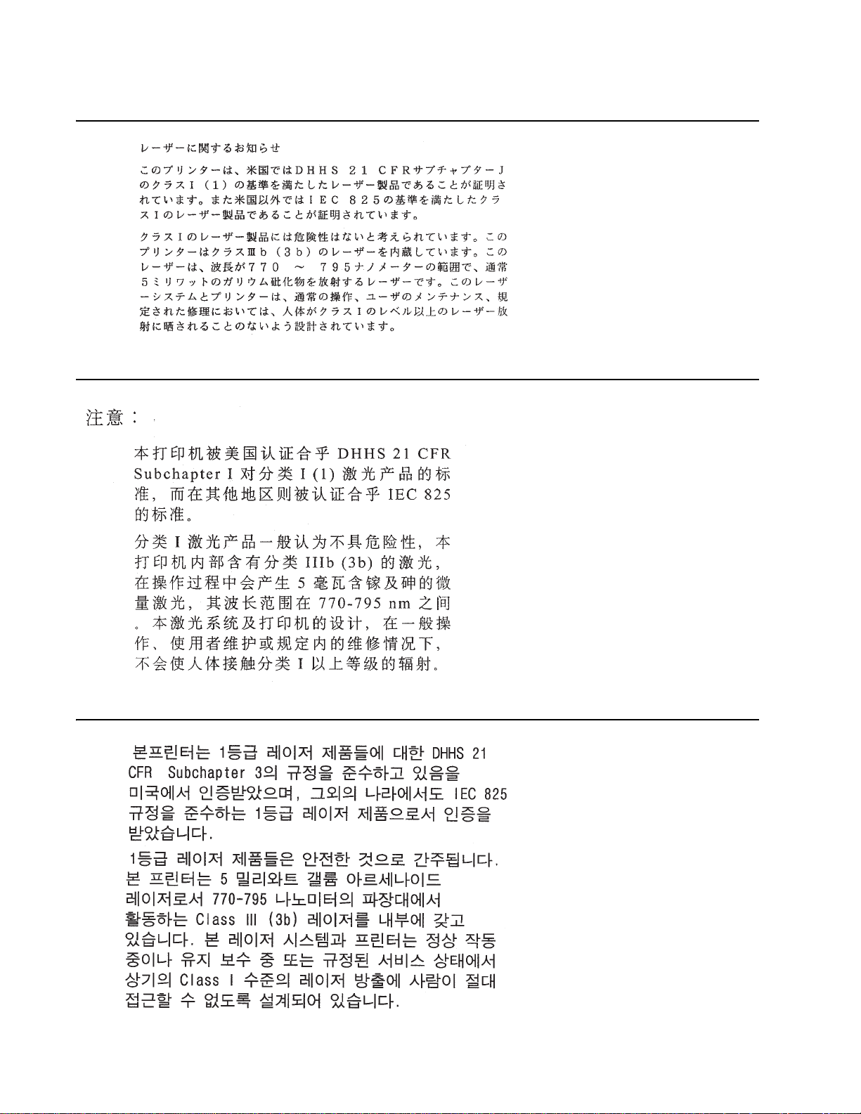
Laser no tice
The printer is certified in the U .S. to confo rm to the requir ements of DHHS 21 CFR Subchapter J for Class I (1)
laser product s, and elsewhere is certified as a Class I laser product conforming to the requirements of IEC
60825-1.
Class I laser products are not considered to be hazardous. The printer contains int ernally a Class IIIb (3b) laser
that is nominally a 5 milliwatt galli um arsenide laser operati ng in the wavelength region of 770-795 nanometers.
The laser system and printer are designed so there is never an y hum an access to laser radiation above a Class
I level during normal operation, user maintenance, or pr escri bed service condition.
Laser
Der Drucker erfüllt gemäß amtlicher Bestätigu ng der USA die Anforderungen der Bestimmung DHHS
(Department of Health and Human Services) 21 CFR Teil J für Laserprodukte der Klasse I (1). In anderen
Ländern gilt der Drucker als Laserprodukt der Klasse I, der die Anforderungen der IEC (International
Electrotechnical Commission) 60825-1 gemäß amtlicher Bestäti gung erfüllt.
Laserprodukte der Klasse I gelten als unschädlich. Im Inneren des Druckers befindet sich ein Laser der Klasse
IIIb (3b), bei dem es sich um einen Galliumarsenlaser mit 5 Milliwatt handelt, der Wellen der Länge 770-795
Nanometer ausstrahlt. Das Lasersystem und der Drucker sind so konzipiert, daß im Normalbetrieb, bei der
Wartung durch den Benutzer oder bei ordnungsgemäßer Wartung durch den Kundendienst Laserbestrahlung,
die Klasse I überstei gen würde, Menschen k einesfalls erreicht.
Avis relatif à l’utilisation de laser
Pour les Etats-Unis : cette imprimante est certifi ée conforme aux provisio ns DHHS 21 CFR ali néa J concernant
les produits laser de Classe I (1). Pour les autres pa ys : cette imprimante répond aux normes IEC 60825- 1
relatives aux produits laser de Classe I.
Les produits laser de Classe I sont considérés comm e des produits non dangereux. Cette imprimante est
équipée d’un l aser de Classe IIIb (3b) (arséniure de gall ium d’une puissance nominale de 5 milliwatts) émettant
sur des longueurs d’onde comprises entre 770 et 795 nanomètres. L’imprimante et son sys tème laser sont
conçus pour impossible, dans des conditions normales d’utilisation, d’entr etien par l’utilisateur ou de révision,
l’exposition à des rayonnements laser supérieurs à des rayonnements de Classe I .
Avvertenze sui prodotti laser
Questa stampant e è certificata negli St ati Uniti per ess ere conforme ai requisiti del DHHS 21 CFR Sottocapitolo
J per i prodotti las er di classe 1 ed è certificata negli altri Paesi come prodotto laser di classe 1 conf orme ai
requisiti del la norma CEI 60825-1.
I prodotti laser di class e non sono con sider ati pericol osi. La stampan te contiene al suo interno un l aser di classe
IIIb (3b) all’arseniuro di gallio dell a potenza di 5mW che opera sulla lunghezza d’onda compresa t ra 770 e 795
nanometri. Il sistema laser e la stampante sono stati progettati in modo tale che le persone a contatto con la
stampante, durante il normale funzionam ento, le operazioni di servizio o quelle di assistenza tecnica, non
ricevano radiazioni laser superiori al livello della classe 1.
Notices and safety information xi
Page 12

5060-4xx
Avisos sobre el láser
Se certifica que, en los EE.UU., esta impresora cumple los requisitos para los productos láser de Clase I (1)
establecidos en el subcapítulo J de la norma CFR 21 del DHHS (Departamento de Sanidad y Servicios) y, en
los demás países, reúne todas las condiciones expuestas en la norma IEC 60825-1 para productos láser de
Clase I (1).
Los productos láser de Clase I no se consideran pel igrosos. La impre sora contiene en su interior un láser de
Clase IIIb (3b) de arseniuro de galio de funcionamiento nomin al a 5 miliv atios en una longi tud de onda de 770 a
795 nanómetros. El sistema láser y la impresora están diseñados de forma que ninguna persona pueda verse
afectada por ningún tipo de radiac ión láser superior al nivel de la Clase I durante su uso normal, el
mantenimiento realizado por el usuario o cualqui er otra situación de servic io técnico.
Declaração sobre Laser
A impressora está ce rtificada no s E. U .A. e m conf ormidade co m os r equi sito s da reg ulamenta ção DHHS 2 1 CFR
Subcapítulo J para a Cla sse I (1) de produt os laser. Em outros locais, está certifi cada como um produto lase r da
Classe I, em conf ormidade com os requisitos da norma IEC 60825-1.
Os produtos lase r da Classe I não sã o conside rados peri gos os. I nternamente , a impr esso ra cont ém um produ to
laser da Classe IIIb (3b), designado laser de arseneto de potássio , de 5 milliwatts ,oper ando numa faixa de
comprimento de onda entre 770 e 795 nanómetros. O sistema e a impressora laser foram concebidos de forma
a nunca ex ist ir qualquer possiblidade de acesso humano a radi ação laser superior a um nív el de Classe I
durante a operação normal, a manutenção feita pelo utilizador ou condições de assist ência prescritas.
Laserinformatie
De printer v oldoet aan de eis en die ges teld w orde n aan ee n laserprodukt v an klass e I. Voor de Ver enigde Stat en
zijn deze eisen vastgelegd in DHHS 21 CFR Subchapter J, voor andere landen in IEC 60825-1.
Laserprodukten van klasse I worden nie t al s ongevaarlij k aangemerkt. De printer is voor zien van een laser van
klasse IIIb (3b), dat wil zeggen een gallium arsenide-laser van 5 milliwatt met e en g ol flengte van 770-795
nanometer . Het laser gedeelt e en de printer zij n zo ont worpen dat bij normaal gebru ik, bij onde rho ud of repar atie
conform de voorschriften, nooit blootstelling mogelijk is aan laserst raling boven een niveau zoals
voorgeschreven is voor klasse 1.
Lasermeddelelse
Printeren er godkendt som et Klasse I-laserprodukt, i overenstemmelse med krave ne i IEC 6082 5-1.
Klasse I-laserprodukter betragtes ikke som farlige. Printeren indeholder internt en Klasse IIIB (3b)-laser, der
nominelt er en 5 milliwatt galliumarsenid laser, som arbejder på bølgelængdeområdet 770-795 nanometer.
Lasersystem et og printeren er udformet således, at mennesk er al drig udsættes for en l aserstråling over Klasse
I-niveau ved normal drift, brugervedligeholdelse eller obligatoriske servicebetingelser.
xii Service Manual
Page 13

5060-4xx
Huomautu s las er laitteesta
Tämä kirjoi tin on Yh dysv alloi ssa lu okan I ( 1) lase rlait teide n DHHS 21 CFR Subchapt er J -mää rityks en muk ainen
ja muualla luo kan I l aserl aitteiden IEC 60825-1 -määri tyksen mukainen.
Luokan I las e r la itt e id e n e i ka ts o ta ol evan vaarallis ia käyttä jä lle . Ki rj oi tt im e s sa on si sä i ne n lu ok an IIIb (3 b ) 5
milliwatin galliumarsenidilaser, joka toimii aaltoalueella 770 - 795 nanometriä. Lase rjärjestelmä ja kirjoitin on
suunnitelt u siten, että käyttäj ä ei al tistu luokan I määrityksi ä voimakkaammall e säteilylle kirj oittimen normaalin
toiminnan, käyttäjän tekemien huoltotoimien tai muiden huoltotoimien yhteydessä.
VARO! Av attaessa ja suojalukitus ohitettaessa olet alttiina näkymä ttömälle lasersäteilylle. Älä katso
säteeseen.
VARNING! Osynlig laserst rålning när denna del är öppnad och spär ren är urkopplad. Betrakta ej strålen.
Laser-notis
Denna skrivare är i USA certifierad att motsvara kraven i DHHS 21 CFR, underparagraf J för laserprodukter av
Klass I (1). I andra länder uppfyller skriv aren kraven för laserprodukter av Kl ass I enligt kraven i IEC 60825-1.
Laserprodukter i Klass I anses ej hälsovådliga. Skrivaren har en inbyggd laser av Klass IIIb (3b) som består av
en laserenhet av gallium-arsenid på 5 milliwatt som arbetar i våglängdsområdet 770-795 nanometer.
Lasersystem et och skrivaren är utformade så att det aldrig finns ris k för att någon person utsätts f ör
laserstrå lning över Klass I-ni vå vid normal användning, underhåll som utförs av användaren eller annan
föreskriv en serviceåtgärd.
Laser-melding
Skriveren er godkjent i USA etter kra vene i DHHS 21 CFR, underkapittel J, for klasse I (1) laserprodukter , og er
i andre land godkjent som et Klasse I-laserprodukt i samsvar med kravene i IEC 60825-1.
Klasse I-la serprodukter er ikke å betrakte som f arlige. Skriveren inneholder internt en klasse IIIb (3b)-laser, som
består av en gallium-arsenlaserenhet som avgir stråling i bølgelengdeområdet 770-795 nanometer .
Lasersystem et og skriveren er utformet slik at personer al dri utsettes for laserstråling ut over klasse I-nivå under
vanlig bruk , vedlikehol d som utf øres av brukeren, eller foreskrevne serviceoperasjoner.
Avís sobre el Làser
Segons ha estat certificat al s Estats Units , aquesta impressor a complei x els req uisits de DHHS 21 CFR, apartat
J, pels productes làser de classe I (1), i segons ha estat certificat en altres llocs, és un producte làser de classe
I que compleix els requisits d’IEC 60825-1.
Els productes l àser de classe I no es consideren perillosos. Aquesta impressora conté un làse r de cl asse IIIb
(3b) d’arseniür de gal.li, nominalment de 5 mil.liwats, i funciona a la regió de longitud d’ona de 770-795
nanòmetres. El sistema làser i la impressora han sigut concebuts de manera que mai hi hagi exposició a la
radiació làser per sobre d’un niv ell de classe I durant una oper ació normal, durant les tasques de manteniment
d’usuari ni durant els serveis que satisfacin les condicions prescrites.
Notices and safety information xiii
Page 14
5060-4xx
xiv Service Manual
Page 15

5060-4xx
Safety information
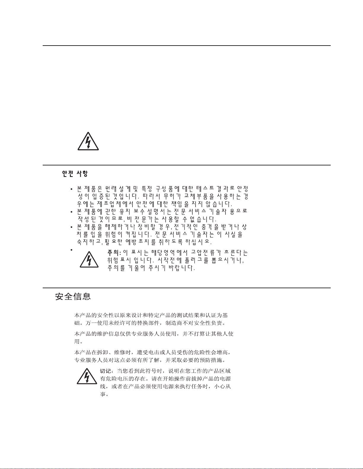
• The safety of this product is based on testi ng and approvals of t he original design and specific
components . The manufacturer is not responsibl e for safety in the event of use of unauthorized
replacement parts .
• The maintenance information for this product has been prepared for use by a professional service person
and is not intended to be used by others.
• There may be an increased risk of electric shoc k and personal injury during disassem bly and servicing of
this product . Pro fessional service personnel should understand this and take necessary precautions.
• CAUTION: When you see th is symbol , ther e is a danger f rom hazard ous v olt age in the ar ea of the
product where y ou ar e working . Unplug the product bef ore you beg in, or use c autio n if t he produc t
must receive power in order to perform the task.
Consignes de sécurité
• La sécurité de ce produit repose sur des tests et des
agréations portant sur sa conception d'origine et sur des composants particulier s. Le fabricant n'ass ume
aucune respon sabilité concernant la sécurité en cas d'utilisation de pièces de rechange non agréées.
• Les consignes d'entretien et de répar ati on de ce produit s'adressent uniquement à un personnel de
maintenance qualifié.
• Le démontage et l'entretien de ce produit pouvant présenter certains risques électriques, le personnel
d'entretien qualifié devra prendre toutes les précautions nécessai res.
• ATTENTION : Ce symbole indique la présence d'une tension dangereuse dans la partie du
produit sur laquelle vous tra vaillez. Débranchez le produit a vant de commencer ou f aites preuve
de vigilance si l' exécution de la t âche exige que le produi t reste sous tension.
Norme di sicurezza
• La sicurezza del prodotto si basa sui test e sull'approvazione del progetto originale e dei componenti
specifici. Il produttore non è responsabile per la sicurezza in caso di sostituzion e non autorizzata delle
parti.
• Le informazioni riguardanti la manutenzione di questo prodotto sono indirizzate soltanto al personale di
assistenza autorizzato .
• Durante lo smontaggio e la manutenzione di questo prodotto,
il rischio di subire scosse elettriche e danni al la persona è più elev ato. Il per sonale di assistenza
autorizzato deve, quindi, adottare le precauzioni necessarie.
• ATTENZIONE: Questo simbolo indica la pre senza di tensione pericolosa nell'area del pr odotto.
Scollegare il pr odotto prima di iniziare o usare cautela se il prodotto deve essere alimentato per
eseguire l'intervento.
Safety information xv
Page 16
5060-4xx
Sicherheitshinweise
• Die Sicherheit di eses Produkts basiert auf Tests und Zulassungen des ursprüngl ichen Modells und
bestimmter Baut eil e. Bei Verwendung nicht genehmigter Ersatztei le wi rd vom Hersteller kei ne
Verantwortung oder Haft ung für die Sicherheit übernommen.
• Die Wartungsinformationen für dies es Produkt sind ausschließl ich für die Verwendung durch ein en
Wartungsfachmann bestimmt.
• Während des Auseinandernehmens und der Wartung des Geräts besteht ein zusät zliches Risiko eines
elektrischen Schlags und körperlicher Verletzung. Das zus tändige Fachpersonal sollte entsprechende
Vorsichtsmaßn ahm en treffen.
• ACHTUNG: Dieses Symbol weist auf eine gefährliche elektrische Spannung hin, die in diesem
Bereich des Produkts auftreten kann. Zie hen Sie vor den Arbeiten am Gerät den Netzstecker des
Geräts, bzw. arbeiten Sie mit großer Vorsicht, wenn das Produkt für die Ausfü hrung der Arbeiten
an den Strom angeschlossen sein muß.
Pautas de Segu ridad
• La seguridad de este prod ucto se basa en pruebas y aprobaciones del diseño original y component es
específico s. El fabricante no es responsable de la seguridad en caso de uso de piezas de repuesto no
autorizadas.
• La información sobre el mantenimiento de este producto está dirigida exclusivamente al personal
cualificado de mantenimiento.
• Existe may o r riesg o de de scarga el éctrica y de dañ os person al es duran te e l desmont aj e y la r eparac ión de
la máquina. El personal cualificado debe ser consciente de este peligro y tomar las precauciones
necesarias.
• PRECAUCIÓN: este símbolo indi ca que el voltaje de la parte del equipo con la que está
trabajando es peligroso. Antes de empezar, desenchufe el equipo o tenga cuidado si, para
trabajar con él, debe conectarlo.
Informações de Segurança
• A segurança deste produto baseia-se em testes e aprovações do mode lo original e de componentes
específico s. O fabricante não é responsável pela segunrança, no caso de uso de peças de substituição
não autorizadas.
• As informações de segurança relativas a este produto dest inam-se a profissionais destes serviços e não
dev em ser utilizadas por outr as pessoas.
• Risco de choques eléct ricos e ferimentos graves durante a desmontagem e manutenção deste produto .
Os profissio nais destes serviços devem estar avis ados deste facto e tomar os cuidados necessários .
• CUIDADO: Quando vir este sí m bolo, existe a possível presença de uma potencial tens ão
perigosa na zona do produto em que está a trabalhar. Antes de começar, desligu e o produto da
tomada eléctrica ou s eja cui dado so caso o pro duto te nha d e estar liga do à corrent e eléc trica para
realizar a tarefa necessária.
xvi Service Manual
Page 17
5060-4xx
Inf ormació de Seguretat
• La seguretat d'aquest producte es basa en l'avaluació i apr ovació del disseny original i els components
específics.
El fabricant no es fa responsable de les qüestions de
seguretat si s'u tilitzen peces de recanvi no autoritzades.
• La informació pel manteniment d’aquest producte està orientada exclusiv ame nt a professional s i no està
destinada
a ningú que no ho sigui.
• El risc de xoc elèctric i de danys personals pot augment ar durant el procés de desmuntatge i de servei
d’aquest producte. El personal professional ha d’estar-ne assabentat i prendre
les mesures con venients.
• PRECAUCIÓ: aquest símbol in dica que el voltatge de la part de l'equip am b la qual esteu
treballan t és perillós . Abans de començar, desendolleu l' equip o extremeu les precaucions si, per
treballar amb l'equip, l'heu de connectar.
Safety i nformation xvii
Page 18

5060-4xx
Preface
This manual contains maintenance procedures for service personnel. It is divided into t he following ch apters:
1. G e n er a l in fo rma tion contains a general descripti on of the printer and the maintenanc e approach used to
repair it. Special tools and test equipment are, as well as general environmental and safety instructions.
2. Diagnostic information contains an error indicator table, symptom tables, and service checks used to
isolate failing field replaceable units (FRUs).
3. Diagnostic aids contains tests and checks used to locate or repeat symptoms of printer problems.
4. R e p ai r in fo rma tion provides instructions for making printer adj ustments and removi ng and installing
FRUs.
5. Connector locations uses illustrations to identify the connector locati ons and test points on the printer.
6. Preventive maintenance contai ns the lubrication specifications and recommendat ions to prevent
problems.
7. Parts catalog contains illus trations and part numbers for individual FRUs.
Appendix A contains service tips and info rmati on.
Appendix B contains representative print samples.
Definitions
Note: A note provides addition al i nformation.
Warning: A warning identifies something that might damage the product hardware or software.
CAUTION: A caution identifies something that might cause a servicer harm.
CAUTION: When you see this symbol, there is a danger from hazardous voltage in the area of the
product where you are working. Unplug the product before you begin, or use caution if the product
must receive power in order to perform the task.
xviii Service Manual
Page 19

5060-4xx
1. General information
The Le xm ark™ C76x is a network-capable color printer that uses electrophotogr aphic technology to deliver high
quality image s, presentation graphics, line art, and text. It prints up to 25 pages per minute (ppm) for both fourcolor and monochrome pri nt jobs.
The flexible design supports a variety of printing needs. For example, if you need the printer to match the color
process used in a particular appli cati on, you can sel ect RGB or CMYK color cor rections . You can also adjust the
printed colors to more closely represent the colors on your comput er di splay.
A variety of con nectivity options enable the printer to be used in all types of system enviro nm ents. You can
attach one internal adapter to support network configurati ons requiring Ethernet, Token-Ring, LocalTalk, serial,
infrared, or additional parallel ports.
The printer has flexible paper handling. It supports a wide variety of paper sizes, and has a standard
multipurpose feeder that makes it easy to print on envelopes, transparencies, labels, card stock, and nonstandard siz e paper. You can add optional i nputs to the base printer, which can increase the printer paper
capacity to 3100 sheets.
The Lexmark C76x (5060-4xx) laser printer is av ailable in four models:
Lexmark C760 5060-401 Non-netw ork
Lexmark C760 5060-402 Network
Lexmark C762 5060-421 Non-network
Lexmark C762 5060-422 N etwork
Tools required for service
Flat-blade screwdriver
#1 Phillips screwdriver, magnetic
#2 Phillips screwdriver, magnetic
#2 Phillips screwdriver, magnetic short-blade
Needlenose pli ers
Diagonal side cutters
Spring hook
Feeler gauges
Analog or digital multimeter
Par allel wrap plug 1319128
Twinax/serial debug cable 1381963
Coax/serial debug cable 1381964
General inf ormation 1-1
Page 20

5060-4xx
Options and features
Lexmark C76x pap er handling options support the Le xmark C750/C752/C76x printers, ho wever the color of the
cove rs do not match the C750 and C752 models. The C76x envelope dra wer is not compatible with the C750.
Note: Do not use Lexmark C750/C752 options on the Lexmark C76x printers .
• 500-Sheet drawer - (includes 500-sheet tray and support unit) installs beneath the printer and holds
appro ximatel y 500 sheet s of 20 lb, 75 g/m
option drawer and high-capacity input tra y. All models of Lexmark C76x.
• 500-Sheet tr ay - tray for special media temporarily replaces the standard tray in a 500-sheet drawer and
holds approximately 500 sheets of 20 lb, 75 g/m
• Duplex option - offers two-side printing. The first optio n under a duplex option m ust be a 500-sheet drawer.
All models of Lexmark C76x.
• 2,000-Sheet drawer (HCIT) - inst all s beneath the printer and below any other optional inp ut sources and
holds approximately 2,000 sheets of 20 lb, 75 g/m
• Output expander - installs above the printer primary output bin to offer an additional output destinatio n.
This holds approximately 650 sheets of 20 lb, 75 g/m
supported. Models 421 and 422.
• 5-Bin mailbox - installs above the printer primary output bin to offer five output destinations in one option.
Each of the five bins supports approximately 100 pages of 20 lb, 75 g/m
above the printer is supported. Models 421 and 422.
• Finisher - offers stapling, hol e punching, offset stacking and an additional output bin. Two models are
ava il able, a short and a tall one . Hole punching f or 2-, 3-, or 4-hole left-edge is av ail able. The single staple
position is the upper left corner. The finisher supports up to 3,000 sheets of non- stapled, non-punched
media. For stapled media, the output bin supports up to 90 stapled sets or 2,700 sheets. The stapler
staples a maximum of 30 sheets per set. Each printer sup ports one finisher. Model s 421 and 422.
• Enve lope drawer - installs beneath the printer, and holds approximately 60 envelopes (20 lb, 75 g/m
to three env e lope dr aw er are supp orted or one env elop e dr aw er and a high-cap aci ty inpu t tra y. Models 421
and 422.
• Outdoor media drawer - installs beneath the printer and holds up to 100 sheets of outdoor media suitable
for outdoor use. Models 421 and 422 only.
• Banner tray - extension all ows printing of banner-wi dth paper. Models 421 and 422 only.
2
paper. Up to three dr a wers are supported simul taneous ly, or an
2
paper. All models of Lexmark C76x.
2
paper. Models 421 and 422.
2
paper. Only one output option above the printer is
2
paper. Only one output option
2
). Up
High performance
Up to 25 ppm black or col or
•
• 500 MHz RISC processor (non-network) or 600 MHz (network)
• 128MB RAM
• Time to first page
– Black: les s than 13 seconds
– Color: less than 15 seconds
Print quality
1200 x 1200 dpi and 4800 CQ.
Heavy volume re liab ility
Up to 4,000-page average monthly duty cycle
•
• Up to 60,000-page maximum duty cycle based on a singl e mon th usage
1-2 Service Manual
Page 21

5060-4xx
Automatic ca l ibr ation
The printer performs an automatic calibration under the following conditions.
• At power-on
• After eight hours of power save r
• Approximately every 500 pages, at the end of a job
• After changing a print cartridge
• After changin g an image tr ansfer unit (ITU)
A manual calibr ation can be initiated b y selecting Color Adjust from the Color Menu.
Resolution
1200 x 1200 dpi (one half printer speed)
•
• 4800 CQ (def ault 00B) (full printer speed)
Toner darkness
Toner darkness settings offer five user-selectable settings to balance print darkness and toner savings. The
higher the setting, the darker the print. The toner darkness default setting is 4. Color level 4 and level 5 are the
same.
The toner darkness set ti ng is availab le through the operator panel under the Print Quality menu or through the
Lexmark PostScript driver.
Setting 12345
Delta toner from default (mono) -50% -30% -15% Default +10%
Delta toner from default (color) -50% -30% -15% Default N/A
Color corr ection setti n g s
The following correction settin gs are available:
• Auto (default): Applies different color correction to each object on the printed page depending upon the
type of object and how the color for each object is specified.
• Off: No color correction is implemented.
• Manual: Allo ws users to customize col or correction output f rom the driver or operator panel.
General inf ormation 1-3
Page 22

5060-4xx
Printer specifications
Description Width Depth Height Weight
Printer
Lexmark C76x (n) 23.8 in.
(604.5 mm)
Lexmark C76x dn
(including duplex option)
Lexmark C76xdtn
(including duplex and optional
23.8 in.
(604.5 mm)
23.8 in.
(604.5 mm)
500-sheet drawer)
Lexmark C762 with Finisher T
(including duplex unit, optional
59.4 in.
(1508.8 mm)
500-sheet drawer, 2000-sheet
drawer, and finishe r T)
Lexmark C762 with maximum
input tr a y s
3
(including duplex u nit ,
23.8 in.
(604.5 mm)
three optional 500-sheet drawer,
and printer stand)
Lexmark C762 with maximum
input sheets
4
(including duplex
23.8 in.
(604.5 mm)
unit, optional 500- sheet drawer,
2000-sheet drawer)
Options
500-sheet drawer 23.8 in.
(604.5 mm)
Duplex optio n 23.8 in.
(604.5 mm)
2,000-sheet tray* 26 in.
(660.4 mm)
Outdoor media drawer 23.8 in.
(604.5 mm)
Envelope drawer 23.8 in.
(604.5 mm)
Output expander* 14.5 in.
(368.3 mm)
5-bin mailbo x* 14.5 in.
(368.3 mm)
Finisher S* 33.5 in.
(850.9 mm)
Finisher T* 33.5 in.
(850.9 mm)
Printer stand 26 in.
(660.4 mm)
1 Includes stabili zer bars on Finisher T and 2000-sheet drawer.
2 Includes stabilizer bars.
3 Printer stack required for Finisher S.
4 Printer stack required for Finisher T.
18.5 in.
(469.9 mm)
18.5 in.
(469.9 mm)
18.5 in.
(469.9 mm)
28.1 in.
(713.7 mm)
18.5 in.
(469.9 mm)
23.8 in.
(604.5 mm)2
18.5 in.
(469.9 mm)
18.5 in.
(469.9 mm)
23.8 in.
(604.5 mm)
18.5 in.
(469.9 mm)
18.5 in
469.9 mm
18.5 in.
(469.9 mm)
18.5 in.
(469.9 mm)
28.1 in.
(713.7 mm)
28.1 in.
(713.7 mm)
24.2 in.
(614.7 mm)
1
2
1
1
2
20.8 in.
(528.3 mm)
24.3 in
(617.2 mm)
28.9 in.
(734.1 mm)
43.5 in.
(1104.9 mm)
41.4 in.
(1051.6 mm)
43.5 in.
(1104.9 mm)
5 in.
(127 mm)
3.5 in.
(88.9 mm)
15.4 in.
(391.2 mm)
5 in.
(127 mm)
5 in.
(127 mm)
7 in
(177.8 mm)
11.5 in.
(292.1 mm)
40.4 in.
(1026.2 mm)
42.5 in.
(1079.5 mm)
4.2 in.
(106.7 mm)
105 lb
(47.7 kg)
118 lb
(53.8 kg)
132 lb
(60 kg)
274.5 lb
(124.7 kg)
179. lb
(81.4 kg)
181 lb
(82.3 kg)
13.5 lb
(6.1 kg)
13.5 lb
(6.1 kg)
49 lb
(22.3 kg)
13.5 lb
(6.1 kg)
13.5 lb
(6.1 kg)
4.5 lb
(2 kg)
8.2 lb
(3.7 kg)
93.5 lb
(42.5 kg)
93.5 lb
(42.5 kg)
20 lb
(9.1 kg)
1-4 Service Manual
Page 23
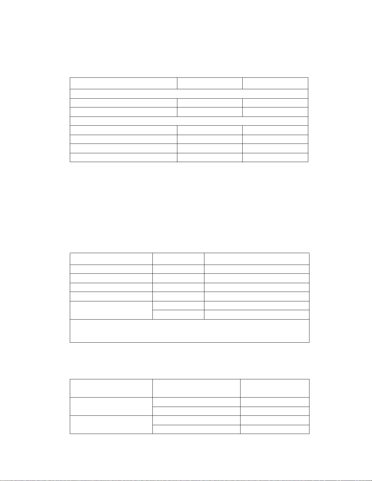
5060-4xx
P o wer and ele ctrica l sp ecific ations
Average nominal power requirements for the base printer configuration (110 volt). (Power levels are shown in
watts.) Maximum current shown in amp ergs.
Printing states Lexmark C76x(n) Lexmark C76xdn
Printing - aver age power
Base model 500 500
All options 540 540
Idle - aver age power
Power Saver On 30 31
Power Saver Off 180 180
Printing - average current (110 V) 5.3 5.3
Printing - maximum current (110 V) 10.2 10.2
Note: Using a 220 to 110 power conv erter with the 110 volt printer is not recommended.
All models are Energy Star compliant.
Electrical specifications
110 Volt model
• 110 to 127 V ac at 47 to 63 hertz (hz) nominal
• 99 to 137 V ac, extreme
Operatin g clea r an ces
Printer Side Model Measurement
Left side All 24 in. (609.6 mm)
Right side Al l 15 in. (381 mm)
Front All 20 in. (508 mm)
Rear All 12 in. (304.8 mm)
Top C76x(n) 42 in. (1,066.8 mm)
C76xdn 34 in. (863.6 mm)
1
Allow 1,219 mm (48 in.) clearance to the right if you are adding a finisher.
2
Allow clearance abov e the print er front door cleara nce and fo r adding opt io ns, such as additio nal
input drawer s, output expander or 5-bin mailbox.
1
2
2
Acoustics
All measurements are made in accordance with ISO 7779 and conform with ISO 9296.
Model Status
Lexmark C76x(n) 4800 CQ printing 52 dBA
Idle (standby) 34 dBA
Lexmark C76x dn 4800 CQ printing 52 dBA
Idle (standby) 34 dBA
1-Meter average sound
pressure
General inf ormation 1-5
Page 24

5060-4xx
Environment
Printer Temperature and Humidity
• Operating
– Temperature: 60 to 90° F (15.6 to 32.3° C)
– Relative hum idity: 8 to 80%
– Maximum wet b ulb temperature: 73° F (22.8° C)
– Altitude: 10,000 ft. (0 to 3,048 meters)
– Atmospheric pressure: 74.6 kPa
• Pow er off
– Temperature: 50 to 110° F (10 to 43.3° C)
– Relative hum idity: 8 to 80%
– Maximum wet b ulb temperature: 80.1° F (26. 7° C)
– Altitude: 10,000 ft. (0 to 3,048 meters)
– Atmospheric pressure: 74.6 kPa
• Ambient operating environment*
– Temperature: 60 to 90° F (15.6 to 32.2° C)
– Relative hum idity: 8 to 80%
• Storage and shipping (packaged printer) with or without print cartridge
Temperature: -40 to 110° F (-40 to 43.3° C)
• Print cartridge
Temperature: -40 to 110° F (-40 to 43.3° C)
*In some cases, performance specif ications (such as paper OCF, EP cartridge usage) are measured at an
ambient condit ion.
Print speed and performance print speed
Media size—Tray 1
Simplex printing on letter-size media (pages per minute), duplex printing on letter-size media (sides per
minute)
Media name Media size 4800 CQ 120 0 x 1200 dpi
Full size media, full rated engine speed
Letter 8.5 in. x 11 in. 25 10
A4 8.3 in. x 11.7 in. 23.5 9.5
Legal 8.5 in. x 14 in. 20 8.1
Full size media, reduced rated engine speed (one half)
Transparencies 8.5 in. x 11 in. 10 10
Card stock 8.5 in. x 11 in. 10 10
Labels 8.5 in. x 11 in. 10 10
Coated Paper 8.5 in. x 11 in. 10 10
Coated Cover 8.5 in. x 11 in. 10 10
1-6 Service Manual
Page 25
5060-4xx
Media size—Tray 1
Smaller sizes, reduced throughput
Nearly narrow (for example ,
B5 or Exec)
Narrow media
a
(for
b
More than 6.8 in., bu t l ess
25 10
than 8.3 in. wide
Less than 6.8 in. wide 10 10
example, A5).
a
The first 25 narrow pages print at rated speed; subseq uent pages print at the speed shown.
b
Once the printer en ters a r educed thr oughput mode as i ndicat ed, the p rinter remains at the gi v en speed af ter
the last sheet of smaller media, until the fuse r ret urn to st andby temperature.
Media size—Multipurpose feeder
Simplex printing on letter-size media (pages per minute), duplex printing on letter-size media (sides per
minute)
Media name Media size 4800 CQ 120 0 x 1200 dpi
Full size media, full rated engine speed
d
Letter 8.5 in. x 11 in. 22.5 9
Duplex (letter) 8.5 in. x 11 in. 22.5 9
A4 8.3 in. x 11.7 in. 21.5 8.6
Legal 8.5 in. x 14 in. 18.6 7.5
d
Full size media, reduced rated engine speed (one half)
Transparencies 8.5 in. x 11 in. 9 9
Cardstock 8.5 in. x 11 in. 9 9
Labels 8.5 in. x 11 in. 9 9
Coated Paper 8.5 in. x 11 in. 9 9
Coated Cover 8.5 in. x 11 in. 9 9
Smaller sizes, reduced throughput
Nea r l y narrow
(for example, B5 or Exec)
a
Narrow media
b, c
More than 6.8 in., bu t l ess
22.5 9
than 8.3 in. wide
Less than 6.8 in. wide 9 9
(for example, A5).
Envelopes
a
The first 25 narrow pages print at rated speed; subseq uent pages print at the speed shown.
b
All envel ope sizes print at 1200 dpi process speeds, as shown.
c
Once the printer enters a r educed thr ough put mode as in dicat ed, the pri nter r emains at t he giv en sp eed afte r
b
All supported sizes 9 9
the last sheet of smaller media, until the fuse r ret urn to st andby temperature.
d
After media has been added to an empty MPF, the fir st t hree pages print at speed. The remainder of the
pages print at the speed indicated until the MPF is empty. the speed change occurs each time media is added
to an empty MPF.
General inf ormation 1-7
Page 26

5060-4xx
Performance
Per formance speed depends on:
• Interface to the host (USB, serial, parallel, network)
• Host system and appli cation
• Page compl exity and content
• Printer options i nstalled or selected
• Av ailable printer memory
• Media size and type
• Resolution
• Printer usage setti ng
Time to first print
Time to first print from standby mode
ab
• Black: <13 seconds
• Color: <15 seconds
Time to first print fro m p ower saver m o de
a
• Black: <120 seconds
• Color: <120 seconds
Notes:
a
All first copy times are measured f or 600 image quality, simplex printing on letter-size paper. The test job
consists of the character “A” follo w ed by a form feed (s ingle-page job). The first copy time is defined as the
elapsed time fro m pressing Enter on the keyboard to the page e xiting to th e output bin . All tests pic k paper
from the primary input tray and the page exits into the primary output bin.
b
Standby times may be longer if the toner cont rol senses that toner fl ow needs to be checke d or adj usted.
Processor
Lexmark C76x Lexmark C76x(n), dn
Processor frequen cy (Mhz) 500 600
Bus frequency (Mhz) 100 100
Duty cycle
Up to 60,000 pages maximum one-time usage
•
• Up to 4,000 pages per month average usage
Memory configuration
DRAM memory Lexmark C76x(n), dn Lexmark C76xdt n, fn
Standard 128MB 256MB
Maximum 512MB 512MB
1-8 Service Manual
Page 27

5060-4xx
Ava ilable memory options
Optional 64MB, 128MB, 256MB and 512MB SDRAM DIMMs are av ailable from Lexm ark. The memory options
are 168-pin synch ronous DRAM DIMMs (dual in-line memory modules) meeting or exceedi ng the followi ng
specifications:
• 100MHz or greater
• 4KB refresh rate
• Unbuffered, non ECC
• x32
• 3.3 V
Unpredictable results may occur if an attempt is made to operate the printer with memory other than SDRAM
DIMM memory with the stated specifications.
Flash Memory Options 16, 32 (Nand Flash)
Expansion
• Memory slot for extra flash or DRAM
• Expansion slot for optional inter face cards
• Code expansion slot (application solution firmware cards)
• On-board hard disk interface (for optional hard disk)
Additional memory may be required for printing complex pages or full-page, high -resolution images in 1200
image quality at rated speeds.
General inf ormation 1-9
Page 28

5060-4xx
Media specifications
Media input and output capacities
The capacities listed below are based on plain paper at 75g/m2.
Media source or output
description
Input
Standard input sources
Tr ay 1
Tr ay 2
Multipurpose tray
Maximum total standard
capacity (sheet s)
Optional available input
sources
3
500-Sheet drawer
(maximum of 3 or only 1
with a 2000-sheet
drawer)
2000-Sheet drawer
(maximum of one)
Envelope drawer
(maximum of 3 or only 1
with a 2000-sheet
drawer)
Outdoor media drawer
Banner tray
Maximum additional drawers
Maximum input capacity
With added drawers (no
high-capacit y input tray)
With added drawer and
high-capacit y input tray
1
1
2
Lexmark
C760
500
N/A
100
600
500-
1500
N/A
N/A
N/A
N/A
1
1100
1100
Lexmark
C760n
500
N/A
100
600
5001500
N/A
N/A
N/A
N/A
1
1100
1100
Lexmark
C760dn
500
N/A
100
600
500-
1500
N/A
N/A
N/A
N/A
1
1100
1100
Capacity (sheets)
Lexmark
C760dtn
500
500
100
1100
500-
1000
N/A
N/A
N/A
N/A
1100
1100
0
Lexmark
C762
500
N/A
100
600
500-
1500
2000
60
100
3
2100
3100
Lexmark
C762n
500
N/A
100
600
500-
1500
2000
60
100
3
2100
3100
Lexmark
C762dn
500
N/A
100
600
500-
1500
2000
60
100
3
2100
3100
Lexmark
C762dtn
500
500
100
1100
500-
1500
2000
60
100
2
2100
3100
1-10 Service Manual
Page 29
5060-4xx
Media source or output
Capacity (sheets)
description
Lexmark
C760
Lexmark
C760n
Lexmark
C760dn
Lexmark
C760dtn
Lexmark
C762
Lexmark
C762n
Lexmark
C762dn
Lexmark
C762dtn
Output
Standard output bin capacity 250 250 250 250 250 250 250 250
Optional outputs
5-Bin mailbox
N/A
N/A
N/A
N/A
500
500
500
(maximum of one)
Output Expander
Finisher S or T
4
N/A
N/A
N/A
N/A
N/A
N/A
N/A
N/A
650
3000
650
3000
650
3000
3000
(maximum of one)
Maximum output paper
250
250
250
250
3900
3900
3900
3900
capacity
1
Two versi ons are available: One configuration is a printer, duplex unit , optional 500-sheet drawer, and a 2000-sheet
drawer; The other con fi guration is a printer, duplex unit, and 3 optional 500-sheet drawers , and a pri nter stand.
2
A maximum combination of three optional 500-sheet drawers or a maxim um com bination of one optional 500-sheet
drawer plus one 2000-sheet drawer is supported on any model.
3
An optional 500-sheet drawer is required for a 2000-sheet Drawer and a Duplex Unit. The first option under a duplex
unit must be a 500-sheet drawer.
Media type
500
650
Media type
500-sheet input
Multipurpose tray
Envelope drawer*
2,000-sheet drawer*
Outdoor media tray*
Banner tray*
Duplex
Standard output
5-bin mailbox*
Output expander*
Finisher to staple,
hole punch, offset stack
stack or with output bi n*
Paper xx x xxxxx x
Card stock x x x x x
Transparencies x x x x
Envelopes x x x x
Vinyl labels x x x x
Paper labels x x xxxx
Pol yester labels x x x x x
Dual web labels xx xxxx
Integrated labels xx xxxx
Outdoor media x
* Available in models 221 and 222 only.
General information 1-11
Page 30

5060-4xx
Media size
8
8
Standard output
8
Finisher to staple,
hole punch, offset
5-bin mailbox
Output expander
stack or with output bin
5, 6, 7
5
5
5
5, 6, 7
5, 6, 7
5, 6, 7
6, 7
Media size supported
A4 8.27 in. x 11.7 in.
(210 mm x 297 mm)
A5 5.83 in. x 8.27 in.
(148 mm x 210 mm)
JIS-B5 7.17 in. x 10.12 in.
(182 mm x 257 mm)
Statement 5.5 in. x 8.5 in.
(140 mm x 216 mm)
4
Letter 8.5 in. x 11 in.
(216 mm x 279 mm)
Folio 8.5 in . x 1 3 in.
(216 mm x 330 mm)
4
Legal 8.5 in. x 14 in.
(216 mm x 356 mm)
Executive 7.25 in. x 10.5 in.
(184 mm x 267 mm)
500-sheet input
Multipurpose tray
Envelope drawer8
2,000-sheet drawer8Outdoor media tray8
Banner tray8
Duplex
xx x xxxxx
xx x xx xx
xx x xxxxx
xx xx xx
xx x x xxxx
xx xxxxx
xx x xxxxx
xx x xxxxx
Banner 11.69 x 36 in.
(297.2 x 914.4 mm)
Outdoor media
9
7 x 10 in. (178 mm x 254 mm) x
7 x 11 in. (178 mm x 279 mm) x
8 x 10 in. (203 mm x 254 mm) x
8.5 x 11 in. (216 x 279 mm) x
Universal
5.5 x 8.27 in. to 8.5 x 14 in. (139.7 x 210
1
xx xxxx
mm to 215.9 x 355.6 mm)
2.75 x 5 in. to 9.01 x 14 in. (69.85 x 127
x xxx
mm to 229 x 355.6 mm)
5.83 x 7.17 in. to 8.5 x 14 in. (148 x 182
xx xxxx
mm to 215.9 x 355.6 mm)
x
1-12 Service Manual
Page 31

5060-4xx
8
8
Standard output
8
Finisher to staple,
5-bin mailbox
Output expander
hole punch, offset
Media size supported
500-sheet input
Multipurpose tray
Envelope drawer8
2,000-sheet drawer8Outdoor media tray8
Banner tray8
Duplex
Envelope
stack or with output bin
7 ¾ Envelope 3.875 i n. x 7.5 in. (98 mm
xx x x
x 191 mm)
9 Envelope 3.875 in. x 8.9 in. (98 mm x
xx x x
225.4 mm)
10 Envelope 4.125 in. x 9.5 in. (105 mm
xx x x
x 241 mm)
DL Enve lope 4.33 in. x 8 .66 in. (110 mm
xx x x
x 220 mm)
C5 Enve lope 6.38 in. x 9 .01 in. (162 mm
xx x x
x 229 mm)
B5 Envelope 6.93 in. x 9.84 in. (176 mm
xx x x
x 250 mm)
Other envelope
3.87 x 6.38 in. to 6.93
xx x x
3
x 9.84 in. (98.4 x 162 mm to 176 x 250
mm)
1
When Universal is selected, the page is formatted for 8.5 x 14 in. (215.9 x 355.6 mm), unless the size is specified in
the software application.
2
Narrow media should be loaded with the length in the feed direction (portrait).
3
When Other Env elope is selected, the page is formatted for 8.5 x 14 in. (215.9 x 355.6 mm) unless the size is
specified in the software applicati on.
4
Statement and Folio are supported as standard size through software only. Tray size sensing must be t urned off
before thi s standard size is visible in the paper-si ze menu on the operato r panel .
5
2-hole punch is supported.
6
3-hole punch is supported.
7
4-hole punch is supported.
8
Option available on models 221 and 222 only.
9
Use only approved outdoor media in the outdoor media tray.
General information 1-13
Page 32

5060-4xx
Input media types and weights
Media Weight
Integrated trays
b, f
Paper
Xerographic or
Card stock - uppe r limit
(grain long)
Transparencies
Labels - upper limit Paper 48 lb bond (180 g/m
Integrated forms Pressure sensitive
Multipurpose Feeder
b, f
Paper
Xerographic or
Specialty papers G loss book 60 to 120 lb book (88 to 176 g/m
Card stock - uppe r limit
(grain long)
Card stock - uppe r limit
(grain short)
Transparencies
Integrated forms Pressure sensitive
Envelopes
f
and optional 500-shee t drawer
business paper
Specialty p apers Glos s
book
Gloss cover 60 to 65 lb cover (162 to 176 g/m
a, f
Index 90 lb (163 g/m2)
Bristol Tag 100 lb (163 g/m
Cover 65 lb (176 g/m
Card stock - upper limit (grain short)
Index Bristol 110 lb (199 g/m2)
Tag 125 lb (203 g/m
Cover 80 lb (216 g/m
i, j
Laser printer type 43 to 45 lb bond (161 to 169 g/m2)
Dual-web paper 48 lb bond (180 g/m
Polyester 59 lb bond (220 g/m
g, h
Vinyl
c
area
Paper base (grain l ong) 20 to 36 lb bond (75 to 135 g/m
business paper
Gloss cover 60 to 65 lb cover (162 to 176 g/m
a, f
Index Bristol 90 lb (163 g/m2)
Tag 100 lb (163 g/m
Cover 65 lb (176 g/m
a, f
Index Bristol 110 lb (199 g/m2)
Tag 125 lb (203 g/m
Cover 80 lb (216 g/m
i, j
Laser printer type 43 to 45 lb bond (161 to 169 g/m2)
Labels - upper limit
Paper 53 lb bond (199 g/m
Dual-web paper 53 lb bond (199 g/m
Polyester 59 lb bond (220 g/m
g, h
Vinyl
c
area
Paper base (grain l ong) 20 to 36 lb bond (75 to 135 g/m
d, e
Sulfite, wood-free or up
to 100% cotton bond
16 to 19.9 lb bond (60 to 74.9 g/m2 grain long)
20 to 47 lb bond (75 to 176 g/m
60 to 120 lb book (88 to 176 g/m
2
)
2
)
a, f
2
)
2
)
2
)
2
)
2
)
2
grain long)
2
grain long)
2
grain long)
92 lb liner (300 g/m2)
(140 to 175 g/m2)
2
)
16 to 19.9 lb bond (60 to 74.9 g/m2 grain long)
20 to 47 lb bond (75 to 176 g/m2 grain long)
2
grain long)
2
grain long)
2
)
2
)
2
)
2
)
2
)
2
)
2
)
78 lb liner (260 g/m2)
Up to 47 lb bond (140 to 175 g/m2)
2
)
16 to 28 lb bond (60 to 105 g/m2)
1-14 Service Manual
Page 33

5060-4xx
Media Weight
2,000-Sheet drawer
b, f
Paper
Xerographic or
business paper
Specialty papers G loss book 60 to 120 lb book (88 to 176 g/m
Gloss cover 60 to 65 lb cover (162 to 176 g/m
a
For 60 to 176 g/m2 paper, g ra in long fiber s are recomm ended. For papers hea vier than 176 g/m2, grain short
16 to 19.9 lb bond (60 to 74.9 g/m2 grain long)
20 to 47 lb bond (75 to 176 g/m
2
grain long)
2
grain long)
2
grain long)
is preferred.
b
Paper less than 75 g/m2 limited to less than 60% re lat ive humidity and i s not supported in duplex.
c
Pressure-sensitive area must enter the printer first.
d
100% cotton content maximum weight is 24 lb bond. 28 lb envelopes are limited to 25% cotton content.
e
28 lb bond envelopes are limited to 25% cotton content.
f
The duplex opti on supports the same types and weight s as the printer except 16 to 19. 9 lb ( 60 to 74.9 g/m2)
grain long paper, transparencies, labels, env elopes or A5 card stock.
g
Vinyl labels are supported only when printing environmen t and media are 20 to 23° C (68 to 90°F).
h
Refer to the Converter Listing on Le xm ark's Hom e Page and Automated F AX system (LEXFAXSM) for
information on whether your vinyl label converter has passed Lexmark's criteria. Refer to the Card Stock and
Label Guide for more details.
i
Lexmark transparency numbers 12A59 40 and 12A5941 are supported from the standard tr ay, optional 500-
sheet trays and the multipurpose feeder.
j
Lexmark transparency numbers 12A51 50 and 12A5151 are supported from the multipurpose feeder only.
Output media types and weights
Media Weight
Standard output bin and optio nal output expander
b, f
Paper
Specialty papers G loss book 60 to 120 lb book (88 to 176 g/m
Card Stock - Upper
limit (grain long)
Card stock – upper
limit (grain short)
Transparencies
a
a
i,j
Labels - upper limit Paper 48 lb bond (180 g/m
Integrated forms Pressure sensitive
Envelopes
d, e
Sulfite, wood-free or up
Xerographic or
business paper
Gloss cover 60 to 65 lb cover (162 to 176 g/m
Index Bristol 90 lb (163 g/m2)
Tag 100 lb (163 g/m
Cover 65 lb (176 g/m
Index Bristol 110 lb (199 g/m2)
Tag 125 lb (203 g/m
Cover 80 lb (216 g/m
Laser printer type 43 to 45 lb bond (161 to 169 g/m2)
Dual-web paper
Polyester 59 lb bond (220 g/m
g, h, k
Vinyl
c
area
Paper bas e
(grain long)
to 100% cotton bond
16 to 19.9 lb bond (60 to 74.9 g/m2 grain long)
20 to 47 lb bond (75 to 176 g/m
2
)
2
)
2
)
2
)
k
48 lb bond (180 g/m2)
92 lb liner (300 g/m2)
Up to 47 lb bond (140 to 175 g/m
20 to 36 lb bond (75 to 135 g/m
16 to 28 lb bond (60 to 105 g/m2)
2
grain long)
2
grain long)
2
grain long)
2
)
2
)
2
)
2
)
General information 1-15
Page 34

5060-4xx
Media Weight
Finisher (Output bin, Offset Stack)
b, f
Paper
Specialty papers G loss book 60 to 120 lb book (88 to 176 g/m
Xerographic or
business paper
16 to 19.9 lb bond (60 to 74.9 g/m2 grain long)
20 to 47 lb bond (75 to 176 g/m
2
grain long)
2
grain long)
Finisher (Staple and Hole Punch)
2
Paper Xerographic or
business paper
16 to 19.9 lb bond (60 to 74.9 g/m
20 to 32 lb bond (75 to 120.4 g/m2 grai n long)
Specialty papers G loss book 60 to 84.5 lb book (88 to 125 g/m
grain long)
2
grain long)
5-Bin Mailbox
2
Paper Xerographic or
business paper
a
For 60 to 176 g/m2 paper, g ra in long fiber s are recomm ended. For papers hea vier than 176 g/m2, grain short
16 to 19.9 lb bond (60 to 74.9 g/m
20 to 24 lb bond (75 to 90 g/m
grain long)
2
grain long)
is preferred.
b
Paper less than 75 g/m2 limited to less tha n 60% r elative humidity and is not supported in duplex.
c
Pressure-sensitive area must enter the printer first.
d
100% cotton content maximum weight is 24 lb bond. 28 lb envelopes are limited to 25% cotton content.
e
28 lb bond envelopes are limited to 25% cotton content.
f
The duplex opti on supports the same types and weight s as the printer except 16 to 19. 9 lb ( 60 to 74.9 g/m2)
grain long paper, transparencies, labe ls, envelopes or A5 card stock.
g
Vinyl labels are supported only when printing environmen t and media are 20 to 23° C (68 to 90°F).
h
Refer to the Converter Listing on Le xm ark's Hom e Page and Automated F AX system (LEXFAX) for
information on whether your vinyl label converter has passed Lexmark's criteria. Refer to the Card Stock and
Label Guide for more details.
i
Lexmark transparency numbers 12A59 40 and 12A5941 are supported from the standard tr ay, optional
500-sheet tra ys and the multipurpose f eeder .
j
Lexmark transparency numbers 12A51 50 and 12A5151 are supported from the multipurpose feeder only.
k The web oiler might be used for extensive use of vin yl or dual web labels. See “Web oiler upgrade kit and
replacements ” on page 1-17.
1-16 Service Manual
Page 35

5060-4xx
Web oiler upgrade kit and replacements
The web oiler removes fuser roll contami nation in machines which run a large num ber
of vinyl or dual web labels. The web oiler w orks wi th all media types and enables the
prolonged use of labels without sacrificing fuser life.
• Web oiler fuser life: 200,000
• Web oiler life: 100,000 pages
• Availability: Order the web oiler upgrade kit.
Upgrade kit
This kit allows you to upgrade your current printer.
Description Part number
115 V web oiler upgrade kit 56P1555
220 V web oiler upgrade kit 56P1556
100 V web oiler upgrade kit 56P1557
The installation of the web oiler upgrade kit converts a standard
Lexmark C76x printer to an oil web capable printer. The web oile r
upgrade kit in cludes an oiler fuser and web oiler.
For replacements for the web oil er, see “Web oiler fuser s and web oiler replacements” on pa ge 6-4.
General information 1-17
Page 36

5060-4xx
Acronyms
BLDC Br ushless DC Motor
BOR Bl a ck On ly Re tra c t
CCyan
CSU Customer Setup
DIMM Dual Inline Memory Module
DRAM Dynamic Random Access Memory
EDO Enhanced Data Out
EP Electrophotographic Process
EPROM Erasabl e Programmable Read-Onl y Me mo ry
ESD Electrostatic Discharge
FRU Field Replaceable Unit
GB Gigabyte
HCIT High-Capacity Input Tray
HCOF High-Capacity Out put Finisher
HVPS High Voltage Power Supply
ITU Image Transfer Unit
KBlack
LASER Light Amplification by Stimulated Emission of Radiation
LCD Liquid Crystal Display
LED Light-Emitting Diode
LVPS Low Voltage Power Supply
M M agenta
MROM Masked Read Only Memory
MS Microswitch
NVRAM Nonvolatile Random Access Memory
OEM Original Equipment Man ufacturer
OPT Optical Sensor
PC Phot oconductor
pel Picture element
POR Power-On Reset
POST Power-On Self Test
PSD P osition Sensing Device
PWM Pulse Widt h Mod ulation
RIP Raster Imaging Processor
ROM Read Only Memory
SDRAM Synchronous Dual Random Access Memory
SIMM Single Inline Memory Module
SRAM Static Random Access Memory
UPR Used Parts Return
V ac Volts alternating current
V dc V olt s direct current
VTB Vacuum Transport Belt
YYellow
1-18 Service Manual
Page 37

5060-4xx
2. Diagnostic information
Start
CAUTION: Unplug power cord from the printer or elect rical outlet before you connect or di sconnect any cable or
electronic board or assembly for personal saf ety and to prevent damage to the printer. Disconnect any
connections between the printer and PCs/peripherals. The printer weighs 47.7 kg (105 lb.) and requires at
least two peopl e to l if t it safely. Make sure your fingers are not under the printer when you lift or set the
printer down.
To determine the corrective action necessary to repair a printer, look for the following information:
• Does the POR stop? Check the “POR (P ower-On Reset) sequence” on page 2-2
• Do you hav e a sym ptom, rather than an error mes sage?
– “Symptom table - base printer” on page 2-3
– “Symptom table - 500-sheet drawer option” on page 2- 4
– “Symptom table - HCIT 2000-sheet option” on page 2-4
– “Symptom table - output expander option” on page 2-4
– “Symptom table - 5-bin mailbox option” on page 2-5
– “Symptom table - finisher (HCOF) option” on page 2-5
• If you have an error message or user mess age, check the following:
– “Error code table” on page 2-6
– “2xx Paper Jams” on page 2-15
– “User attendance messages” on page 2-27
– “Service checks” on page 2-41 for individual error messages
• Additional information can be found at the following locations:
– “Sub error code table” on page 2-18
– “Understanding the printer operator panel” on page 2-21
– “Service checks” on page 2-41
Note: There may be printer error messages that are not contained in this service manual. Call your next level
support for assistance.
Diagnostic information 2-1
Page 38

5060-4xx
POR (Power-On Reset) sequence
The foll owing is an example of the events that occur during the POR sequence for the base machine with no
paper handling options installed .
1. Power the machine on.
2. +5V LED (Power ON) on the system board comes on.
3. Operator Panel LED comes on solid.
4. All diamonds appear on the display.
5. While loading code, dots scro ll across the display.
6. The following is an e xam ple of the screen that displays after the code is load ed.
128MB 600Mhz
128MB = Amount of Memory 600Mhz = Processor Speed
7. Performing Self Test is displayed.
8. Fuser drive motor turns on.
9. Fuser fan turns on.
10. RIP fan turns on.
11. Heartbeat LED on system boards turns on.
12. Fuser lamps turn on.
13. Vacu um transport belt fan turns on.
14. ITU Missing is posted if the ITU is missi ng.
15. Fuser Missing is posted if the fuser is missing.
16. Close Door is posted if the front cover is open.
17. Busy is displayed.
18. Operator panel LED blinks.
19. Redrive exit roller turns.
20. Any cartridge errors are posted such as a defective cartridge, Return Program information, or missing
cartridge.
21. Any applicable ma int enance messages displ ay such as 80 Fuser Maintenance or 83 ITU Maintenance.
22. One of the toner low messages appears when applicable: 88 Yellow Toner Low, 88 Magenta Toner Low,
88 Cyan Toner Low , or 88 Black Toner Low.
23. Color calibration may be initiated. Thi s is displ ayed if one of the following occurs:
• The printer detect s at po wer on, or t he fro nt cover is closed, that a new or di ff erent toner c artridge has
been installed.
• The printer detects at power on when the cover is closed that a new or different ITU has been
installed.
• The printer detects at power on that the fuser temperature is below 60° C .
• When coming out of power saver if po wer saver has been active for eight hours or longer.
• If the printer is turned on when a calibration cycle was in progress s ince the printer was last powered
off.
24. Ready is display ed.
2-2 Service Manual
Page 39

5060-4xx
Sympto m tables
Symptom table - base printer
Symptom Action
Fus e r fan fai ls to run or is no isy G o t o “925 error code” on page 2-85.
RIP fan fails to run or is noisy Go to “927 error code” on page 2-86.
VTB fan fails to run or is noisy Go to “926 error code” on page 2-85.
Excessive fuser drive motor assemb ly noise Go to “Excessive fuser drive motor assembly
Machine inoperat ive: Fans don’t turn, engine not on,
lights not on, and none of the printer functions work.
Close Door displays constantly, unable to clear the
message, POR incomplete
Operator panel: One or more buttons do not work Go to “Operator panel LCD/sta tus LED/ buttons
Operator panel: Display is blank, printer does not
sound 5 beeps, but printer is not inoperative
Operator P anel: Ope rator pane l display s all diamon ds
continuousl y, sounds 5 beeps, and POST inoper ative
Operator panel: One pel or random pels are missing Replace the “Operat or panel” on page 4-53.
Paper feed problems, base printer Go to “2xx Pape r Jams” on page 2-15.
Paper feed problems, integrated tray Go to “Tray 1 service chec k” on page 2-142.
Printer prints black only, no colors Make sure that the printer is not set up to prin t black
Print quality: 100% single color printed
• All black print
• All cyan print
• All magenta print
• All y ellow p rin t
Print quality: Blank page (no image) Go to “Blank page (no image)” on page 2-130.
Print quality: Evenly spaced hori zontal marks or lines
on the printed page
Print quality: Black line Black horizontal lines are most likely caused by a
Print quality: Magenta, cyan, or yellow lines. “Vertical lines or streaks” on page 2-134 or
Print quality: Colored l ines, streaks , or sm udges Go to “Vertical lines or streaks” on page 2-134 or
Print quality: Light l ines or streaks appear on the
printed page
Print quality: Light print Go to “Light print over the entire page” on
Print quality: Missing colors Go to
Print quality: Uneven printing Go to “Uneven printing” on page 2-137.
noise” on page 2-124.
Go to “AC and DC power service check” on
page 2-105.
Go to “C lose door/HVPS/pr inthead interl ock sw itch
service check” on page 2-110.
service check” on page 2-125.
Replace the “Operator panel” on page 4-53.
Go to “Operator panel LCD/status LED/butt ons
service check” on page 2-125.
only. If the printer is set up correctly, check the Black
Retract Motor and gear s for correct operation. If the
gears are operating correctly, replace the Retract
Motor Assembly. If this does not correct the problem,
go to “Black only retract (BOR) service check” on
page 2-109.
Go to “Entire page is mostly one color —Full bleed
planes in one color” on pa ge 2-131.
Go to “Vertical lines or streaks” on page 2-134.
shorted charge roll in the print cartridge. Repl ace the
black print cartridge.
“Horizontal lines or streaks” on page 2-134.
“Horizontal lines or streaks” on page 2-134.
Go to “Light lines or streaks appear on the page”
on page 2-139.
page 2-133.
“Missing color s—Complete or partially
missing color planes ” on page 2-132.
Diagnostic information 2-3
Page 40

5060-4xx
Symptom Action
Print quality: P oor color alignment Go to “Poor color alignment” on page 2-136.
Print quality: Toner on the back of the page Go to “Toner is on the back of the printed page ” on
Print quality: Toner smears or rubs off the page Go to “Toner smears or rubs off the page with no
Print quality: Multiple horizontal lines Go to “Vertical lines or streaks” on page 2-134
page 2-139.
error code displa yed” on page 2-138.
Symptom table - 500-sheet drawer option
Symptom Action
Printer fails to recognize the option is installed Go to “The base printer does not recognize that
The tray x autocompensator fails to retract, stays in
down position
Paper Low message appears when adequate paper
is installed (tray x)
Paper Out mess age appears when adequat e paper is
installed (tr ay x)
Tray x does not detect size media is installed Go to “Tray x does not detect size media insta lled”
Paper jams in the option tray Go to “2xx Paper Jam s” on p age 2-15.
Symptom table - HCIT 2000-sheet option
Symptom Action
Printer fails to recognize the option is installed Go to “Printer does not recognize that the HCIT
HCIT does not function. Ther e is no r esponse. The
HCIT is inoperativ e.
HCIT does not recogniz e the correct paper size Go to “HCI T 2000-sheet option does n ot recognize
Paper j ams in the HCIT Go to “2xx P aper Jams” on page 2-15.
tray x is installed.” on page 2-102.
Go to “Tray x autocompensator fail s to retract,
stays in down position.” on page 2-103.
Go to “The printer d etects pa per lo w in tra y x when
adequate paper is installe d in the t ray .” on
page 2-103.
Go to “The printer detects paper out in tra y x when
adequate paper is installe d in the t ray .” on
page 2-104.
on page 2-104.
2000-sheet option is insta lled.” on page 2-122.
Go to “HCIT i noperative” on page 2-123.
the size paper selected.” on page 2-124.
Symptom table - output expander option
Symptom Action
Printer fails to recognize the option is installed. The
paper feeds into the standard bin.
Remove P aper - Output Bin x is display ed and c annot
be cleared
Printer does not display Output Bin Full G o to “No indication that bin x is full or no
Excessive static electricity buildup Go to “Problems with excessive static electricity
2-4 Service Manual
Go to “Output expander option service check” on
page 2-127.
Go to “Remove Paper - Output Bin x is displayed,
POST is incomplete unable to clear the message.”
on page 2-128
indication that bin x is near full.” on page 2-129.
buildup.” on page 2-129.
Page 41

5060-4xx
Symptom table - 5-bin mailbox option
Symptom Action
Printer fails to recognize the option is installed. P aper
feeds into th e standard bin.
Ready Bin x Full displays and won’t clear Go to “Read y bin x full message - may be able to
Bin x is full but no message displays that Bin x is full “Bin x full - no message that bin x is full messa ge”
271 Paper J am appe ars, paper does not fe ed in to the
bin selected.
Symptom table - finisher (HCOF) option
Symptom Action
Check Finisher displayed, unable to clear messag e Go to “Check Finisher displayed, unable to c lear
Finisher is inoper ative Go to “Finisher is inoperative, or not recognized”
Front door i s open and no error message appears Go to “Front door is open, no indication on
Inoperative fan Go to “ Fan in finisher inoperative” on page 2-119
Full chad box, no message appears G o to “No indication that the chad box is full, no
Chad Box Full message appears when box is not full Go to “Chad Box Full message when chad box is
Paper jams in the finisher (HCOF) option Go to “2xx Pape r Jams” on page 2-15.
Go to “The printer does not recognize one or more
output options as installed.” on page 2-99.
clear message and will f eed paper into bin
selected.” on page 2-100
on page 2-100
Go to “Paper does not feed into the bin selected.
271 Paper Jam - chec k bin 1 message” on
page 2-101
message” on page 2-117
on page 2-118
display” on page 2-119
message” on page 2-120
not full” on page 2-120
Diagnostic information 2-5
Page 42

5060-4xx
Error code table
Error code Action
9xx service errors
900 RIP Software Error Go to “900 RIP Software Error” on page 2-83.
902 Service Engine Error 0 General Engine Sof tware Errors 902 through 907 indicate an
904 Engine Software Interface violation by RIP - Check all cabling and connections to the
906 Engine RAM Error Eng ine RAM Err or - Repl ace the syst em boa rd. See “Syst em boar d ” on
907 Engine Flash Error Engine Flash Error - The system board might be causing the error code.
920 Color Calibrat e Unrecoverable TPS Gain Error - Replace the ITU asse mb ly. See “ITU
921 Color Calibrate Unrecoverable TPS Error - Replace the ITU assembly. See “ITU
922 Color Calibrat e Unrecoverable TPS Inva li d Belt - Replace the ITU assembly. See “ITU
925 Fa n Stal led Fuser fan - Go to “925 error code” on page 2-85.
926 Fa n Stal led VTB fan - Go to “926 error code” on page 2-85.
unrecoverable engine software error. The system board may cause this
type of error. Turn the printer off and on to try and clear the error code. If
this does not fix the problem after several attempts, call your next level
support before replacing the system board.
system board. If no problem is found, replace the system board. See
“System board” on page 4-72.
page 4-72.
Try the following:
Reflash the system board with the correct le vel code. If this does not fix
the problem, replace the system board. See “System board” on
page 4-72.
assembly” on page 4-44.
assembly” on page 4-44.
assembly” on page 4-44.
927 Fan Stalled RIP Fan - Go to “927 error code” on page 2-86.
930 LV Power Supply Unable to find zero crossover point - Replace the LVPS. See “LVPS
931 LV Power Supply Invalid AC Frequency - The AC power line frequency may be incorrect.
939 RIP Engine Comm The RIP processor cannot communicate with the engi ne processor.
940 TMC Error - Cyan Cyan TMC switch failure - Go to “940 error code” on page 2-87.
941 TMC Error - Magenta Magenta TMC switch failure - Go to “941 error code” on page 2-89.
942 TMC Er ro r - Yellow Yellow TM C switch failure - Go to “942 error code” on page 2-91.
943 TMC Error - Black Black TMC switch failure - Go to “943 error code” on page 2-93.
953 NVRAM Failure NVRAM Chip Failure system board - Replace the paper size sensing
954 NVRAM Fai lur e NVRAM CRC failure - Replace the paper size se nsing board. See
2-6 Service Manual
assembly” on page 4-46.
Go to “AC power service check” on page 2-105.
Replace the syste m board. See “System board” on page 4-72.
board. See “Paper size sensing board” on page 4-57.
“Paper size sensi ng board” on page 4-57.
Page 43

5060-4xx
Error code Action
955 Code CRC <loc> System board - This error indicat es that the Code ROM or NAND failed
956 Service <xxxx>
System Board
957 System Board ASIC Failure Replace the sy stem board. See “System board” on page 4-72.
958 NAND Failure Replace the system board. See “System board ” on page 4-72.
960 RAM Memory Error RAM soldered on board is bad. Replace the syst em bo ard. See “System
961 RAM Memory Error There is an error in the memory inst alled in th e memory opt ion sl ot on the
964 Emulation Error Download emulation CRC fai lur e has occurred. The following actions
975 Standard Network
or
Network Card x
the CRC check. The location of th e failure is i ndicated by <loc>. Replace
the system board. See “System board” on page 4-72.
A four digi t code displays <xxxx>. Go to “956 service error” on
page 2-95.
board” on page 4-72.
system board. If another memory option is available, switch the memory
options to isolate the problem. If you do not have a spare memory option
to switch, then replace the memory instal led. If this does not fix the
problem, replace the “System board” on page 4-72.
may be taken:
1.Disable the Downl oad Em ulation
2.Program the download emulation into the code overlay SIMM, again.
3.If the problem is not res olved, replace the code overlay SIMM and
download emu lat ion, again.
Unrecognizable network Errors 975 through 979 indicate a failure with
the standard net work port located on th e system boar d or a network car d
in the specified slot x, x=1, 2 or 3. Replace the car d in t he specified slot.
976 Standard Network Unreco verable software or error in network for network card x. If u n a ble
978 Standard Network
or
Network Card x
979 Standard Network
or
Network Card X
980 <device> comm Engine is experiencing unreliable communications to the specified
981 <device> comm Engine protocol vi olation detected by the specified dev ice.
982 <device> comm Communications error detected by the specified devic e.
to clear the error message, check the following:
• If installed, check network car d for correct instal lation.
• If correct ly i nstalled, replace the network card.
• If a network card is not installed, replace the system board.
Bad checksum while programming network Network Card x port.
Flash parts failed while programming Network Card x port.
device.
Errors 980 through 984 indicate the specifi ed device has detected a
Paper Port communication failure .
•Engine
• Duplex Option
•Tray x (where x=1,2,3,4, or 5)
Output Bin (where x=1,2,3,or 6)
Note: This message is used for single bin output devices.
Bins x to y (where x to y= 1 to 5, 2 to 6, or 6 to 10)
Diagnostic information 2-7
Page 44

5060-4xx
Error code Action
983 <device> comm Invalid command received by the specified device.
Note: This message is used for multiple bin output devices.
Note: Check the autoconnects abov e and below the failing option to
make sure they are seated an d connected correctl y. Go to service check
for the device indicated.
984 <device> comm Inval id command parameter received by the specified devic e.
990 <device> This error message indicates that an equipment check condition has
991 <device> S ystem Ca r d
Failure
1xx service errors
100 ITU Error ITU stall - Go to “100 ITU Error” on page 2-41.
occurred in the specified devic e, but the devi ce is unable to identify the
exact com ponent failure. Go to “For 990 Service Error - Tray x, x=Tray
2, 3, 4 or 5, this is the tray that has a problem or needs service.” on
page 2-96.
Note: <device> can be one of the follow ing:
• Duplex option
•Tray x (where x=1,2,3,4, or 5)
• Output bin x (where x=1,2,3, or 6)
Note: This message is used for single bin output devices.
Output bin x to y (where x=1 to 5, 2 to 6, or 6 to 20)
Note: This message is used for multiple b in output devices. Go to the
service check for the device indicated.
This error message indicates that a device has detected an equipm ent
check in its system board.
Note: <device> can be one of the following;
• Duplex option
•Tray x (where x=1,2,3,4 or 5)
• Output bin x (where x=1,2,3, or 6)
Note: This message is used for single bin output devices.
• Output bin x to y (where x=1 to 5, 2 to 6, or 6 to 20)
Note: This message is used for multiple b in output devices. Go to the
service check for the device indicated.
101 ITU Error Invalid ITU memory - Replace “ITU assembly” on page 4-44.
102 ITU Error ITU shorted thermistor - Replace “ITU assem bly” on page 4-44.
103 ITU Error Memory load error - Replace “ITU assembly” on page 4-44.
104 ITU Error ITU
106 Printhead Error Cyan printhead lost Hsync
2-8 Service Manual
belt tra cking - Go to “104 ITU Error” on page 2-44.
Check for the correct installation of all the cables to the system board
assembl y and to th e p rinthead assembly; J8, and J9 on th e system
board. Go to “System board” on page 5-8. If the cables are connected
correctly to the system board and to the printhead assembly, go to
“Printhead diagnostics” on page 3-1.
Note: Do not adjust or replace a ny printhead before performing checks in
“Printhead diagnostics” on page 3-1.
Page 45

5060-4xx
Error code Action
107 Printhead Error Magenta printhead lost Hsync
Check for the correct installation of all the cables to the system board
assembly and to the printhead assembly; J11 and J12 on the system
board. Go to “System board” on page 5-8. If the cables are connected
correctly to the system board and to the printhead assembly, go to
“Printhead diagnostics” on page 3-1.
Note: Do not adjust or replace a ny printhead before performing checks in
“Printhead diagnostics” on page 3-1.
108 Printhead Error Yellow printhead lost Hsync
Check for the correct installation of all the cables to the system board
assembl y and to t he print head ass emb ly; J7 and J 8 on the s yst em boar d.
Go to “System board” on page 5-8. If the cables are connected
correctly to the system board and to the printhead assembly, go to
“Printhead diagnostics” on page 3-1.
Note: Do not adjust or replace a ny printhead before performing checks in
“Printhead diagnostics” on page 3-1.
109 Printhead Error Black printhead lost Hsync
Check for the correct installation of all the cables to the system board
assembly and to the printhead assembly; J12 and J13 on the system
board. Go to “System board” on page 5-8. If the cables are connected
correctly to the system board and to the printhead assembly, go to
“Printhead diagnostics” on page 3-1.
Note: Do not adjust or replace a ny printhead before performing checks in
“Printhead diagnostics” on page 3-1.
110 Printhead Error No first Hysnc - cyan
Check for the correct installation of all the cables to the system board
assembl y and to t he print head ass emb ly; J8 and J 9 on the s yst em boar d.
Go to “System board” on page 5-8. If the cables are connected
correctly to the system board and to the printhead assembly, go to
“Printhead diagnostics” on page 3-1.
Note: Do not adjust or replace a ny printhead before performing checks in
“Printhead diagnostics” on page 3-1.
111 Printhead Error No first Hysnc - magenta
Check for the correct installation of all the cables to the system board
assembly and to the printhead assembly; J11 and J12 on the system
board. Go to “System board” on page 5-8. If the cables are connected
correctly to the system board and to the printhead assembly, go to
“Printhead diagnostics” on page 3-1.
Note: Do not adjust or replace a ny printhead before performing checks in
“Printhead diagnostics” on page 3-1.
112 Printhead Error No first Hysnc - yellow
Check for the correct installation of all the cables to the system board
assembl y and to t he print head ass emb ly; J7 and J 8 on the s yst em boar d.
Go to “System board” on page 5-8. If the cables are connected
correctly to the system board and to the printhead assembly, go to
“Printhead diagnostics” on page 3-1.
Note: Do not adjust or replace a ny printhead before performing checks in
“Printhead diagnostics” on page 3-1.
Diagnostic information 2-9
Page 46

5060-4xx
Error code Action
113 Printhead Error No first Hysnc - black
Check f or the cor rec t ins tallati on of all t he c able s to t he sy stem boar d and
in the printhead assembly; J12 and J13 on the system board. Go to
“System board” on page 5-8. If the cables are connected correct ly, go
to “Printhead diagnostics” on page 3-1.
Note: Do not adjust or replace a ny printhead before performing checks in
“Printhead diagnostics” on page 3-1.
114 Printhead Error A black printhead servo error has been detected.
Verify all packing m aterial have been removed from the printer and the
printhead.
If error persis ts, see “Printhead diagnostics” on page 3-1.
115 Printhead Error A cyan printhead serv o error has been detected.
Verify all packing m aterial have been removed from the printer and the
printhead.
If error persis ts, see “Printhead diagnostics” on page 3-1.
116 Printhead Error A magenta printhead servo error has been detected.
Verify all packing m aterial have been removed from the printer and the
printhead.
2-10 Service Manual
If error persis ts, see “Printhead diagnostics” on page 3-1.
Page 47

5060-4xx
Error code Action
117 Printhead Error A yellow printhead servo error has been detected.
Verify all packing m aterial have been removed from the printer and the
printhead.
If error persis ts, see “Printhead diagnostics” on page 3-1.
120 Fuser Error Wrong fuser lam p - hot roll - replace the fuser assemb ly. See “Fuser
assembly” on page 4-35.
121 Fuser Error Wrong fuser lamp - BUR - replace the fuser assembly. See “Fuser
assembly” on page 4-35.
122 Fuser Error Fuser below temp eratu re when pri nti ng - hot rol l - g o to “122 error code”
on page 2-46.
123 Fuser Error Fuser below temperature when printing - BUR - go to “123 erro r code”
on page 2-46.
124 Fuser Error Fuser over temperature - hot roll - go to “124 error code” on page 2-47.
125 Fuser Error Fuser over temperature - BUR - go to “125 error code” on page 2-47.
126 Fuser Error Fuser open thermistor hot roll - go to “126 error code” on page 2-48.
127 Fuser Error Fuser open thermistor BUR - go to “127 error code” on page 2-48.
128 Fuser Error Fuser under temperat ur e in st andby - hot ro ll - go to “ 128 erro r co de” on
page 2-49.
129 Fuser Error Fuser under temperature in standby - BUR - go to “129 error code” on
page 2-49.
130 Fuser Error Fuser failed to reach standby temperature - hot roll - go to “130 error
code” on page 2-50.
131 Fuser Error Fuser failed to reach standby temperature -BUR - go to “131 error
code” on page 2-51.
132 Fuser Error Fuser cold hot roll - go to “132 error code” on page 2-52.
133 Fuser Error Fuser cold roll - BUR - go to “133 error code” on page 2-53.
134 Fuser Error Fuser lamp on too long hot roll - go to “134 error code” on page 2-54.
135 Fuser Error Fuser lamp on too long BUR - go to “135 error code” on page 2-54.
136 Fuser Error Fuser cam position not found - go to “136 error code” on page 2-54.
140 Motor DC motor accel stall - registrat ion (staging)- repl ace the “Registration
motor” on page 4-69.
If this does not fi x the problem, replace the “System board” on
page 4-72.
Diagnostic information 2-11
Page 48

5060-4xx
Error code Action
141 Motor DC pick motor excessi v e PWM - regi st ration ( stagi ng) motor - replac e the
142 Motor DC pick motor, over speed - registration (staging) motor - replace the
143 Motor DC pick motor, no encoder feedback - registration (st aging) motor -
144 Motor DC motor accel stall - autocompensator motor - replace the
145 Motor DC motor excessive PWM autocompensator motor - repl ace the
146 Motor Autocompensator motor over speed , aut ocom pensator motor - replace
147 Motor There is no autocompensator DC motor feedback. Replace the
“Registration motor” on page 4-69.
If this does not fi x the problem, replace the “System board” on
page 4-72.
“Registration motor” on page 4-69. If this does not fix the problem,
replace the “Syst em board” on page 4-72.
replace the “Regi stration motor” on page 4-69. If this does not fix the
problem, replace the “System board” on page 4-72.
“Autocompensator pick assembly” on page 4-20.
If this does not fi x the problem, replace the “System board” on
page 4-72.
“Autocompensator pick assembly” on page 4-20.
If this does not fi x the problem, replace the “System board” on
page 4-72.
the “Autocompensator pick assembly” on page 4-20 If this does not
fix the problem, replace the “System boar d” on page 4-72.
“Autocompensator pick assembly” on page 4-20. If thi s does not fix
the problem, replace the “System board” on page 4-72.
148 Motor ITU belt motor, unable to lock - go to “148 error code” on page 2-56.
150 Motor Black cartridge motor unable to lock - go to “150 error code” on
151 Motor Magenta cartridge motor unable to lock - go to “151 error code” on
152 Motor Cyan cartridge motor unable to lock - go to “152 error code” on
153 Motor Yellow Cartridge motor unable to lock - go to “153 error c ode” on
154 Motor ITU belt motor - lost lock - go to “154 err or code” on page 2-60.
156 Motor Black cartridge motor lost loc k - go to “156 error code” on page 2-61.
157 Motor Magenta cartridge motor lost lock - go to “157 error code” on
158 Motor Cyan cartridge motor lost lock - go t o “158 error code” on page 2-62.
159 Motor Yellow cartridge motor lost lock - go to “159 error code” on page 2-63.
160 Motor ITU belt BLDC motor mfg. unknown - go to “160 error code” on
162 Motor Black cartridge BLDC motor mfg. unknown - go to “162 error code” on
page 2-57.
page 2-58.
page 2-58.
page 2-59.
page 2-62.
page 2-63.
page 2-64.
163 Motor Magenta cartridge BLDC motor mfg. unknown - go to “163 er ro r c od e ”
2-12 Service Manual
on page 2-64.
Page 49

5060-4xx
Error code Action
164 Motor Cyan cartridge BLDC motor mfg. unknown - go to “164 error code” on
165 Motor Yellow cartridge BLDC mot or mfg. unknown - go to “165 error code” on
167 Motor The incorrect configur at ion ID. See “Web oiler fuser ki t inst allat ion ” on
168 Motor Unknown manufacture type - perform “Motor Detect” on page 3-17. If
169 Motor Mirror motor lock not achieved - black - go to “Printhead diagnostics”
170 Motor Mirror motor lost loc k - black - go to “Printhead diagnostics” on
171 Motor Mirror motor lock not achieved - cyan - go to “Printhead diagnostics”
172 Moto r Mirror moto r los t lo ck - cyan - go to “Printhead diagnostics” on
page 2-64.
page 2-65.
page 4-80 to set configuration ID.
you do not find the problem after performing the test, call your next level
support.
on page 3-1.
Note: Do not adjust or replace a ny printhead before performing checks in
“Printhead diagnostics” on page 3-1.
page 3-1.
Note: Do not adjust or replace a ny printhead before performing checks in
“Printhead diagnostics” on page 3-1.
on page 3-1.
Note: Do not adjust or replace a ny printhead before performing checks in
“Printhead diagnostics” on page 3-1.
page 3-1.
Note: Do not adjust or replace a ny printhead before performing checks in
“Printhead diagnostics” on page 3-1.
173 Motor Mirror motor lock not achieved - magenta - go to “Printhead
174 Motor Mirror motor lost lock - magenta - go to “Printhead diagnostics” on
175 Motor Mirror motor lock not achieved - yellow - go to “Printhead diagnostics”
176 Motor Mirror motor lost lock - yellow - go to “Printhead diagnostic s” on
196 Service Thermal System The printer has detected an error in the printhead thermal drift
199 Service Reflash RIP The printer has detected an invalid version of the RIP code and must be
diagnostics” on page 3-1.
Note: Do not adjust or replace a ny printhead before performing checks in
“Printhead diagnostics” on page 3-1.
page 3-1.
Note: Do not adjust or replace a ny printhead before performing checks in
“Printhead diagnostics” on page 3-1.
on page 3-1.
Note: Do not adjust or replace a ny printhead before performing checks in
“Printhead diagnostics” on page 3-1.
page 3-1.
Note: Do not adjust or replace a ny printhead before performing checks in
“Printhead diagnostics” on page 3-1.
compensation system. Per form the “Drift Sensors” on page 3-16.
reflashed to the appr oved version. Contact your next level support.
Diagnostic information 2-13
Page 50

5060-4xx
Programming errors - P10 1 through P116
These error codes may be displayed whenever a new code upgrade has been attempted. It is possible that the
wrong type of code, network versus non-ne twork, or a corrupted file was probably sent to the printer. Verify that
the correct type of code is being flashed to the printe r.
The foll owing displays whenever a programming error occurs while programming the RIP code.
Programming
Error P xxx
Error code Description
P101
P104
P102 Device size error - The fl ash file was too large to fit on the flash device.
P103 Copyright too large - The copyright message was too large to fit into one block.
P104 Not used
P105 Invalid package - A network file was used to prog ram a non-network printer , or a
P106 Not used (invalid chip select)
P107 Not used (invalid Block Table (IBT) is not valid)
P108 Invalid socket - The socket ID requested for programming is not valid.
P109 Package size error - An update file was used to program the printer, but the
P110 Too many bad blocks - The Invali d Block Table is too large to fit in the allocated
P111 Boot Loader too large - The Boot Loader (zloader) is too large to fit into block 0.
P112 Invalid DLE - An upddle.fls file was used to update the DLE code on printer wit h a
P113 Not used (no partition specified)
Bad file type - The proper signature was not found in the file.
non-network fi le was used to program a network printer .
package did not fit within the space allocated in the Master Boot Record.
space.
firmware card installed, but the DLE was not found on the firmware card.
P114 Bad secure header - The secure header for the DLE was invalid.
P115 Invalid package - A non-DLE “full” file was sent to a flash that already had a DLE
P116 User Flash partition in use - An attempt was made to program code over a user
2-14 Service Manual
partition. (You must use erasele.fls to wipe out the DLE partition first).
flash part.
Page 51

5060-4xx
2xx Paper Jams
User primary
message
200 Paper Jam
Clear Paper Path
201 Paper Jam
Clear Paper Path
User secondary
message
Leave sheets in
Finisher are a 5
Leave sheets in
Finisher are a 5
Explanation
Primary: This message indicat es that a paper jam has
occurred at or near the printer Input Sensor . Open the
printers left doo r (Paper Jam Removal Door) to access the
jammed media.
Secondary: If sheets have been accumulated to be stapled
when the jam is detected, the printer alternately flashes the
primary and secondary messages indicating the
accumulated sheets should not be removed during jam
clearing.
Note: When the secondary message is displayed, if the
accumulated sheets are removed the printer will not reprint
these sheets . Also i f th e print j ob is c omple ted, t he portion of
the job printed after the jam will not be stapled.
If removing the jammed media does not fix the prob lem, go
to “200 Paper Jam—Options and multipurpose feeder”
on page 2-68 or “200 Paper Jam—Tray 1” on page 2-66.
Primary: Media has jammed at or before the fuser sensor.
Open the printer lower right or center door to acce ss the
jammed media.
Secondary: If sheets have been accumulated to be stapled
when the jam is detected, the printer alternately flashes the
primary and secondary messages indicating the
accumulated sheets should not be removed during jam
clearing.
Note: When the secondary message is displayed, if the
accumulated sheets are removed the printer will not reprint
these sheets . Also i f th e print j ob is c omple ted, t he portion of
the job printed after the jam will not be stapled.
If removing the jammed media does not fix the prob lem, go
to “201 Paper Jam” on page 2-70.
202 Paper Jam
Clear Paper Path
Leave sheets in
Finisher are a 5
Primary: Media has jammed at the fuser. Open the printer
right door to access the jam area.
Secondary: If sheets have been accumulated to be stapled
when the jam is detected, the printer alternately flashes the
primary and secondary messages indicating the
accumulated sheets should not be removed during jam
clearing.
Note: When the secondary message is displayed, if the
accumulated sheets are removed the printer will not reprint
these sheets . Also i f th e print j ob is c omple ted, t he portion of
the job printed after the jam will not be stapled.
If removing the jammed media does not fix the prob lem, go
to“202 Paper Jam” on page 2-71.
Diagnostic information 2-15
Page 52

5060-4xx
User primary
message
230 Paper Jam
Clear Paper Path
24x Paper Jam
Clear Paper Path
User secondary
message
Leave Job in
Finisher are a 5
Leave Job in
Finisher are a 5
Explanation
Primary: Paper has most likel y jammed in the duple x opt ion.
Remove th e duplex tray to access the jam.
Secondary: If sheets have been accumulated to be stapled
when the jam is detected, the printer alternately flashes the
primary and secondary messages indicating the
accumulated sheets should not be removed during jam
clearing.
Note: When the secondary message is displayed, if the
accumulated sheets are removed the printer will not reprint
these sheets . Also i f th e print j ob is c omple ted, t he portion of
the job printed after the jam will not be stapled.
If removing the jammed media does not fix the prob lem, go
to “230 Paper Jam” on page 2-73.
Primary: This paper jam message can apply to both the
500-sheet Opti on Tray, envelope opt ion, special media
option, and HCIT option. Tray x (x=2 through 4). Open the
option side access door and then the tray.
Secondary: If sheets have been accumulated to be stapled
when the jam is detected, the printer alternately flashes the
primary and secondary messages indicating the
accumulated sheets should not be removed during jam
clearing.
Note: When the secondary message is displayed, if the
accumulated sheets are removed the printer will not reprint
these sheets . Also i f th e print j ob is c omple ted, t he portion of
the job printed after the jam will not be stapled.
If removing the jammed media does not fix the prob lem, go
to “24x Paper jam” on page 2-74.
250 Paper Jam
Clear Paper Path
271 Paper Jam
Clear Paper Path
Leave Job in
Finisher are a 5
Leave Job in
Finisher are a 5
Primary: Paper is jammed in the MPF .
Secondary: If sheets have been accumulated to be stapled
when the jam is detected, the printer alternately flashes the
primary and secondary messages indicating the
accumulated sheets should not be removed during jam
clearing.
Note: When the secondary message is displayed, if the
accumulated sheets are removed the printer will not reprint
these sheets . Also i f th e print j ob is c omple ted, t he portion of
the job printed after the jam will not be stapled.
If removing the jammed media does not fix the prob lem, go
to “250 Paper Jam” on page 2-78.
Primary: Paper ha s jammed at Output Bin 1. Open the doo r
of Bin 1 to access the jammed media.
Secondary: If sheets have been accumulated to be stapled
when the jam is detected, the printer alternately flashes the
primary and secondary messages indicating the
accumulated sheets should not be removed during jam
clearing.
Note: When the secondary message is displayed, if the
accumulated sheets are removed the printer will not reprint
these sheets . Also i f th e print j ob is c omple ted, t he portion of
the job printed after the jam will not be stapled.
If removing the jammed media does not fix the prob lem, go
to “271 Paper Jam - check bin 1” on page 2-80.
2-16 Service Manual
Page 53

5060-4xx
User primary
message
272 Paper Jam
Clear Paper Path
280 Paper Jam
Clear Paper Path
User secondary
message
Leave Job in
Finisher are a 5
Leave sheets in
Finisher are a 5
Explanation
Primary: Media is jammed in the 5-Bin Mailbox Option.
Open the rear door of opt ion to access the jammed media.
Secondary: If sheets have been accumulated to be stapled
when the jam is detected, the printer alternately flashes the
primary and secondary messages indicating the
accumulated sheets should not be removed during jam
clearing.
Note: When the secondary message is displayed, if the
accumulated sheets are removed the printer will not reprint
these sheets . Also i f th e print j ob is c omple ted, t he portion of
the job printed after the jam will not be stapled.
If removing the jammed media does not fix the prob lem, go
to “272 Paper Jam - check bin x” on page 2-81.
Primary: Media has jammed in the Finisher Option. Open
the finishe r opt ion front door to access the jammed pages.
Secondary: If sheets have been accumulated to be stapled
when the jam is detected, the printer alternately flashes the
primary and secondary messages indicating the
accumulated sheets should not be removed during jam
clearing.
Note: When the secondary message is displayed, if the
accumulated sheets are removed the printer will not reprint
these sheets . Also i f th e print j ob is c omple ted, t he portion of
the job printed after the jam will not be stapled.
If removing the jammed media does not fix the prob lem, go
to “280 Paper Jam” on page 2-82.
282 Staple Jam
Check Stapler
Remove Job from
Finisher
The stapler de vice detects a paper jam during normal
stapler operation such as when printing and stapling jobs.
Check staple r are f or jam in acc umulat or or stap ler. Remove
stapler cartridge to check for staple jam.
Note: After the error has been cleared, the printer does not
reprint any pages which existed in the accumulator for
stapling.
The foll owing actions can be tak en while either the primary
or secondary messages are displayed:
Press Go to initiate priming and resume printing.
Diagnostic information 2-17
Page 54

5060-4xx
Sub error code table
Use this table to t roubleshoot the printe r when 9xx and 2xx Error Codes are displayed.
When a 9xx or 2xx error code is displa yed, press and hold Return and press Select to vie w the Sub err or code.
Sub error code Explanation
2D 00 No media available in duplex option.
2D 01 Leading edge of image position has reached image halt location.
2D 02 Paper jam detected. Sensor S2 was activated at an unexpected time.
2D 03 Paper jam detected. Sensor S2 was not activated withi n the t imeout period.
2D 04 Paper jam detected. Sensor S2 did not deactivate during the timeout period.
2D 05 Paper jam detected. Sensor NM was activated at an unexpected time.
2D 06 Paper jam detected. Sensor NM did not deactivate during the timeout period.
2D 07 Paper jam detected. The fuser exit sensor w as activated at an une xpected time.
2D 08 Paper jam detected. The fuser exit sensor did not deactivate by t he previous page or the
2D 09 Paper jam detected. The fuser exit sensor did not deactivate during the timeout period.
2D 0A Paper jam detected. A paper jam detected in the Duplex Option.
2D 0B Paper jam detected. A paper jam detected in Tray 2.
2D 0C Paper jam detected. A paper jam detected in Tray 3.
2D 0D Paper jam detected. A paper jam detected in Tray 4.
2D 0E S2 sensor was not made with in timeout period (source is MPF).
2D 0F S2 sensor was made too early.
2D 10 S2 sensor w as m ade too early (source is MPF).
2D 11 Media v ersus registration error is out of acceptable bounds.
2D 12 Media v ersus registration error is out of acceptable bounds (source is MPF) .
2D 13 Prism sensor detected incorrect media (source is MPF).
2D 14 Prism sensor detected different media from the tray sensor.
2D 15 Paper jam detected. A paper jam detected in Stacker 1.
2D 16 Paper jam detected. A paper jam detected in Stacker 2.
current page did not act ivate the fuser e xit sensor within the timeout period.
2D 17 Paper jam detected. A paper jam detected in Stacker 3.
2D 18 Paper jam detected. A paper jam detected in Stacker 4.
2D 19 Paper jam detected. A paper jam detected in Stacker 5.
2D 1A Paper jam detected. A paper jam detected in Stacker 6.
2D 1B Sensor (S2) has been activated or obstructed.
2D 1C Fuser narrow media sensor obstructed.
2-18 Service Manual
Page 55

5060-4xx
Sub error code Explanation
2D 1D Fuser exit senso r obstructed.
2D 1E Duple x sensor(s) obstructed.
2D 1F Tray 2 sensor obstructed.
2D 20 Tray 3 sensor obstruc ted.
2D 21 Tray 4 sensor obstruc ted.
2D 22 Pass thru sensor in Stacker 1 obstructed.
2D 23 Pass thru sensor in Stacker 2 obstructed.
2D 24 Pass thru sensor in Stacker 3 obstructed.
2D 25 Pass thru sensor in Stacker 4 obstructed.
2D 26 Pass thru sensor in Stacker 5 obstructed.
2D 27 Pass thru sensor in Stacker 6 obstructed.
2D 28 Paper jam detected. A paper jam det ected in the Duplex opti on.
2D 29 Paper jam detected. A paper jam det ected in Tray 2.
2D 2A Paper jam detected. A paper jam detected in Tray 3.
2D 2B Paper jam detected. A paper jam detected in Tray 4.
2D 2C Duplex input motor error detected, the engine detected a stall condition.
2D 2D Duplex input motor error detected, the engine detected a PWM error.
2D 2E Duplex input motor error detected, the engine detected a motor encoder error.
2D 2F Duplex reversing motor error dete cted, the engine detected a stall condition.
2D 30 Duplex reve rsi ng m otor error detected, t he engine has detected a PWM error conditi on.
2D 31 Duplex reve rsi ng m otor error detected, t he engine detected a motor encoder error.
2D 32 Tray 2 pick motor stall error detected.
2D 33 Tray 2 pick motor PWM error detected.
2D 34 Tray 2 pick motor encoder error detected.
2D 35 Tray 2 feed motor stall error detected.
2D 36 Tray 2 feed motor PWM error detected.
2D 37 Tray 2 feed motor Encoder error detected.
2D 38 Tray 3 pick motor stall error detected.
2D 39 Tray 3 pick motor PWM error detected.
2D 3A Tray 3 pick motor Encoder error detected.
2D 3B Tray 4 feed motor stal l error detected.
2D 3C Tray 4 f eed motor PWM error detected.
2D 3D Tray 4 f eed motor Encoder error detected.
Diagnostic information 2-19
Page 56

5060-4xx
Sub error code Explanation
2D 3E Tray 4 pick motor stall error detected.
2D 3F Tray 4 pic k motor PWM error detected.
2D 40 Tray 4 pick motor Encoder error detected.
2D 41 Tray 4 feed motor stall error detected.
2D 42 Tray 4 feed motor PWM error detected.
2D 43 Tray 4 feed motor encoder error detected.
2D 44 Registration (staging) Motor stall error detected when picking media from the MPF.
2D 45 Autocompensator motor stal l error detected when pic king media from the MPF.
2D 46 Autocompensator motor stal l error detected when pic king media from Tray 1.
2D 47 Registration (staging) motor PWM error detected.
2D 48 Autocompensator motor PWM error detected when picking m edia from the MPF.
2D 49 Autocompensator motor PWM error detected when picking m edia from Tray 1.
2D 4A Registration (staging) motor encoder error detected.
2D 4B Autoc om pensator motor encoder error detected when picking media from the MPF.
2D 4C Autocompensa tor motor encoder error detec ted when picking media from Tray 1.
2D 4E Output e xpander sensor was not acti vated by the media.
2D 4F Topmost output option sensor obstructed.
2D 50 5-Bin mailbox pass thru sensor was not deacti vated b y the previous page or not activat ed
2D 51 5-Bin mailbox pass thru sensor was not activated by the media.
2D 52 5-Bin mail box sensor was not deactivated by the previous page or not ac ti vated by the
2D 53 5-Bin mailbox sensor was not activated by the media.
2D 54 Expander did not declare page complete.
2D 55 5-Bin mailbox did not declare page complete.
2D 56 5-Bin mail box S1 broke early.
2D 57 5-Bin mail box S2 broke early.
2D 58 Output expander sensor broke early.
2D 59 Detected earl y break of fuser exit sensor.
by the current page.
current page.
2D 5A Finisher detected staple jam.
2-20 Service Manual
Page 57

5060-4xx
Understanding the printer operator panel
The operator panel has five buttons, a display, and a light that flashes when the printer is processing a job
indicated b y the Busy message.
Operator panel buttons
Button Function
Go Press Go to:
• Return to the Ready state if the printer is offline (the Ready message does not
appear on the display).
• Exit printer menu s and return to the Ready state.
• Clear some operator panel messages.
• Resume printing aft er loading paper or clearing pape r jams.
•Exit Power Saver.
If you have changed printer setti ngs from the operator pane l menus, press Go before
sending a job to print. The printer must displa y Ready for jobs to print.
Menu Press Menu to:
• Take the printer offline (out of the Re ady state) and enter the menus. When the
printer is offline, press Menu to scroll th rough the menus and menu items .
• List the menu items in the Job Menu (during Busy state).
For menu items that have numerical values, such as Copies, press and hold Menu to scroll
through the list of values. Release the button when the number you want appears.
If you see a Menu Di sabl ed message , y ou wi ll n ot be ab le t o chan ge def au lt set ting s. You can
still clear message s and se lect it ems fr om the Job M enu when pri ntin g. When you send a job
to print, change printe r properties to select the setting s you want for your job.
Select Press Select to:
• Open the menu show n on the second line of the display.
• Save the display ed me nu item as the new user def ault setting.
• Clear certain messages fr om the di splay.
• Continue print ing after the Change <x> message appears.
Return Press Return to go back to the previous menu level or menu item.
Stop Press Stop at the Ready, Busy or Waiting me ssage to temporarily take the printer offline.
1,2,3,4,5,6 Use the number s located next to the nam es of the buttons to enter your personal
The message changes to Not Ready. No date is lost.
identification number (PIN) after you send a confidential job.
See the menu map fo r a brief overview of the printer men us available from the operator panel.
Diagnostic information 2-21
Page 58

5060-4xx
Select a menu or menu item for more details.
Color Menu
Color Adjust
Color Balance
Color Correction
Color Samples
Color Saver
Manua l Col or
Print Mode
Print Resolution
To ner Darkness
Finishing Me nu
Duplex
Duplex Bind
Copies
Blank Pages
Collation
Separator Sheets
Separator Source
Hole Punch
Offset Pages
Stap le Job
Staple Prime Src
Multipage Print
Multip age Order
Multipage Vie w
Multip age Border
Help Menu
Print All
Help Guide
Printing Guide
Supplies Guide
Print Q ua lit y
Color Quality
Media Guide
Connection Guide
Moving Guide
Print Defects
Jam Clearance
Job Menu
Cancel Job
Reset Printer
Print Buffer
Cancel Fax
Confidential Job
Held Jobs
Reset Active Bin
Network Menu
PCL SmartSwitch
PS SmartSwitch
MAC Binary PS
NPA Mode
Network Buffer
Job Buffering
Network <x> Setup
Std Net Setup
Parallel Menu
PCL SmartSwitch
PS SmartSwitch
NPA Mode
Parallel Buffer
Job Buffering
Advanced Status
Protocol
Honor Init
Parallel Mode 1
Parallel Mode 2
MAC Binary PS
PCL Emul Menu
Font Sourc e
Font Name
Point Size
Pitch
Symbol Set
Orientation
Lines pe r Page
A4 Width
Auto CR after LF
Auto LF after CR
Tray Renumber
Paper Menu
Paper Source
Paper Size
Paper Type
Custom Types
Output Bin
Configure Bins
Overflow Bin
Assign Type/Bin
Substitute Size
Configure MP
Paper Texture
Paper Weight
Paper Loadi ng
Universal Setup
PostScript Menu
Print PS Error
Font Priority
Image Sm oo thing
Serial Menu
PCL SmartSwitch
PS SmartSwitch
NPA Mode
Serial Buffer
Job Buffering
Serial Protocol
Robust XON
Baud
Data Bits
Parity
Honor DSR
Setup Menu
Printer Language
Printer Usage
Power Saver
Resource Save
Download Target
Print Timeout
Auto C o ntinue
Wait Timeout
Jam Recovery
Page Protec t
Display Language
Alarm Control
Hole Punch Alarm
Staple Alarm
Toner Alarm
Job Accounting
Print Area
Black & White Lock
Supplies Menu
<color> Toner
Oiler
Was te Bo ttle
USB Menu
PCL SmartSwi tch
PS SmartSwitch
MAC Binary PS
NPA Mode
USB Buffer
Job Buffer ing
Utilities Menu
Print Menus
Print Net <x> Setup
Print Fonts
Print Directory
Factory Defaults
Format Flash
Defragment Flas h
Format Disk
Job Acct Stat
Hex Trace
Color Alignment
Coverage Esti mator
2-22 Service Manual
Page 59

5060-4xx
Color Menu
Use the Color Menu to adjust print quality and customize color printing.
Note: Values marked by an asterisk (*) are the factory default settings.
Menu Item Purpose Values
Color Adjust To manually rec alibrate the color
Color
Balance
Color
Correction
conv ersion tables , adjusting for variations
in output that can occur as a result of
changing conditions, such as room
temperature or humidity.
To provide users with the abilit y to make
subtle color adjustments to printed output
by increasi ng or decre asing the amount of
toner being used for each color plane
individually.
Note: This functio n is onl y applied to files
printed using the PostScript driv er.
To adjust the printed color to better match
the colors of other out put devices or
standard color systems.
Note: Due to the differences between
additiv e and subtractive colors, certain
colors that app ear on your monitor are
impossible to duplicate on your printer.
No selections e xist for this operation.
Pressing Select initiates this operation.
Cyan -5, -4, -3, -2, -1, 0*, 1 , 2 , 3, 4, 5
Magenta
Yellow
Black
Reset
Defaults
Auto* Applies different color con version
Off No color correction is implemented.
Manual Lets you customize the color
• -5 is maximum decrease
• 5 is maximum increase
Sets values for Cyan, Magenta,
Yellow, and Black to 0 (zero).
tables to each object on the printed
page depending upon the type of
object and how the color for each
object is specified.
conv ersion tables applied to each
object on the printed page depending
upon the type of object and how the
color for each object is specified.
Customization is performed using the
selections av ai lab l e under th e Man ual
Color menu item.
Color
Samples
To assist users in selecting col ors to be
printed. Users can print color samples
pages for each of the RGB and CMYK
color conversion tables used in the printer.
The color samples pages consist of a
series of colored boxes along with the
RGB or CMYK combination that creat es
the color obse rved f or each particu lar bo x .
These pages can be useful in helping
users decide which RGB or CMYK
combinations to use in their softwar e
applications to create the desired printed
color output .
sRGB Display Prints RGB samples using
sRGB Display color conversion
tables.
sRGB Vivid Prints RGB samples using
sRGB Vivid color conversi on tables.
Off–RGB Prints RGB samples using Off (or no)
color conversion tables.
Vivid Prints RGB samples using Vivi d color
conver sion tabl e s.
US CMYK Prints CMYK samples us ing
US CMYK color conversion tables.
Euro CMYK Prints CMYK samples using
Euro CMYK color conver sion tables.
Off–CMYK Prints CMYK samples using Off (or
no) color conversion tables.
Vivid CMYK Prints CMYK samples using
Vivid CMYK color conversion tables.
Diagnostic information 2-23
Page 60

5060-4xx
Menu Item Purpose Values
Color Saver To conserve toner. If selected, this setting
overrides Toner Darkness settings.
Manual Color To let users customize the RGB or CMYK
color conversions applied to each object
on the printed page . Col or conversion of
the data specified using RGB
combinations can be customized based
on object type (text, graphics, or image).
Off* Prints using Toner Darkness setting.
On Applies a lower Toner Darkness level.
Toner Darkness setting is ignored.
RGB Image • sRGB Display*: Applies a color
RGB Te xt • sRGB Display
RGB
Graphics
CMYK • US CMYK (default for 120V
conv ersion table to produce
output that approximates the
colors displayed on a computer
monitor.
• sRGB Vivid: Increases color
saturation for the sRGB Display
color conversion table. Preferr ed
for business graphics and text.
• Off: No color conversion is
implemented.
• Vivid: Applies a color conversion
table that produces brighter, more
saturated col o rs.
• sRGB Vivid*
•Off
• Vivid
machines): Applies a color
conv ersion table to approximate
SWOP color output.
• Euro CMYK (default for 220V
machines): App lies color
conv ersion table to approximate
EuroScale color output.
• Vivid CMYK: Increases color
saturation for the US CMYK color
conver sion tabl e.
• Off: No color conversion is
implemented.
Print Mode T o determine whether file s are printed in a
Print
Resolution
monochrome grayscale or in color.
To define the number of dots printed per
inch (dpi).
2-24 Service Manual
Color*
Black & White
4800 CQ* Default setting.
1200 dpi Provides t he highest resol ution outp ut
which generat es preferable output f or
certain images and gra phics. This
setting also provides increased gloss.
Page 61

5060-4xx
Menu Item Purpose Values
Toner
Darkness
To lighten or darken printed output, or
conserve toner.
Note: Setting Toner Darkness to values of
1, 2, or 3 is only eff ective when using th e
PostScript driver.
5 If Print Mode is Black & White, a
4* Default toner darkness setting.
3 Reduction in toner consumption.
2 Further reduction in toner
1 Maximum reduction in toner
Utilities Menu
Use the Utilit ies Men u t o print a vari ety of listi ngs r elating to a v ailab l e print er res ources , print er set tings , and p rint
jobs. Other menu items let you set up printer hardware and troubleshoot printer problems.
Menu Item Purpose Values
Color
Alignment
Coverage
Estimator
To print a color alignment test page, which
can be used to properly align how colors
are printed.
You are prompted to enter align ment va lues
for each setting (A...L).
Provides an estim ate of the percent
coverage of cyan, magenta, yellow, and
black on a page . Thi s es timat e is print ed on
the page.
0...20 (10*) Used to indicate which line is mos t
Off* Percent coverage is not printed.
On Prints the estimated percentage of
setting of 5 increases toner density
and darkness to all print jobs (PCL or
PostScrip t) . If Print Mode is Colo r, a
setting of 5 is the same as 4.
consumption.
consumption.
acceptable f or alignments A...L.
coverage for each color on the page.
Defragment
Flash
Factory
Defaults
To retrieve storage area lost when
resources are deleted from flash memory.
Do not turn off the printer whil e th e flash is
defragmenting.
To return your printer sett ings to the fa cto ry
default v alues.
Yes Printer tr ansf er s all resou rce s stor ed in
flash memory to printer memory and
then reformats the flash memory
option. When the f ormat oper ation is
complete, the re sources are loaded
back into flash memory.
No Printer cancels the request to
Restore • All menu items are returned to the
Do Not
Restore
defragment the flash memory.
factory def ault values except:
- Display Language.
- All settings in the Parallel
Menu, Serial Menu, Network
Menu, and USB Menu.
• All downloaded resources (fonts,
macros, and s ymbol sets ) in print er
memory (RAM) are deleted.
(Resources residing in flash
memory or on the hard disk are
unaffected.)
User-defined setti ngs remain.
Diagnostic information 2-25
Page 62

5060-4xx
Menu Item Purpose Values
Format Disk To format the print er har d disk.
Warning: Do not turn off the printer while
the hard disk is formatt ing.
Format Flash To format the flash memory.
Warning: Do not turn off the printer while
the flash i s formatting .
Hex T race To help isolate the source of a print job problem. With Hex Trace sel ected, all data sent to the printer i s
printed in hexad ecimal and character r epresentation. Control codes are not executed.
To exit Hex Trace, turn the printer off or reset the printer f rom the Job Menu.
Job Acct Stat To print a listing of all job statistics stored
on the hard disk, or to clear all statist ics on
the disk.
Print Directory To print a lis t of all the resources stored in f lash memory or on the hard disk.
Note: Print Directory is available only when either a nondef ective flash or di sk is installed and
formatted, and Job Buffer Size is not set t o 100% .
Print Fonts To print a sample of all the fonts avail able
for the selected printer language.
Yes Deletes any data stored on the hard
disk and prepares the device to
receive new resources.
No Cancels the request to fo rmat the hard
disk and leaves current resources
stored on the disk.
Yes Deletes any data stored in flash
memory and prepares the flash
memory to receive new resources.
No Cancels the req uest t o f ormat t he flash
memory and leaves current resources
stored in flash memory.
Print Prints all statistics a vailable for the
most recent print jobs.
Clear Deletes all accumulated job statistics
from the hard disk.
PCL Fonts Prints a sample of all printer fonts
available for PCL emulation.
PS Fonts Prints a sample of all printer fonts
Print Menus To print a listing of the current user default values, the in stalled options, the amount of installed printer
Print Net <x>
Setup
memory, and the status of printer supplies.
To print information relating to the internal print server and the network settings defi ned by the
Network <x> Setup men u it em in the Network Menu.
available for PostScript emulation.
2-26 Service Manual
Page 63

5060-4xx
User attendance messages
Note: A secondary message only displays i f the finish er option is installed. Use the “Sub error code table” on
page 2-18 to help diagnose paper jam proble ms .
User primary
message
Setup Required T his message is displayed when the printer has detected at
A Alignment = x.x* This m essage is displa yed when an ITU Alignment
Change
<custom Type Name>
<input source>
Change
<input source>
<Custom String>
Change
<input source>
<Size> Change
<input source>
<type> <size>
User secondary
message
Explanation
POST, that packing material is still installed and must be
removed. The user should verify that the machine is
properly setup.
Press Go and Reflash Code.
Procedure is in process and the printer is prompting the
user for t he A ali gnm ent value. Alignment values for A
through L (=x.x*) -7 to +7 in 0.5 increments.
• Enter the alignm ent value and press Select to continue
to the next al ignment value.
• To stop the alignment operation pr ess Go or Return.
This messa ge is displ a yed when the prin ter is req uesti ng the
operator to ch ange the media installed in one of the input
sources. <input source>= Tray 1 thr ough 5, MPF or Env el ope
Feeder.
One of the following is displayed on line two.
The user can define a name for each of the custom types
(Custom 1 through 6)
Reattach Output Bin x
Reattach Bins x-y
Check Tray x
Connection
Check Duplex
Connection
Check Finisher
Connection
These messages are displaye d anytime the printer loses
communicat ions with one of the following options:
• Output Bin x (x=1,2 or 3)
•Bins (
•Tray x (x=2,3,4 or 5)
•Duplex
• Finisher
The specified option could have been removed from the
printer , maybe to clear a paper jam or to remove the option
or the option may be still installed but experienc ing a
communications problem. The option may not be fully
installed or it may have a hardware failure. The most likely
cause of this message is a failure to rea ttach the option
when remov ed to service a printer intervention.
If the option w as temporarily removed or not connected
properly, then reattach or reconnect it. When the opti on is
recognized, the printer automatically clears the attendance
message and continues. Press Go to execute a
configura tion c hange which wil l tel l th e print er the optio n has
been Hot Unplugged removed. In this case it is assumed
that the user wants to continue to operate t he prin ter with
the option removed. If the probl em continues, turn the
printer off and back on. If the message continues to be
displayed, turn the printer off, remove the option and call for
service.
x-y=1 through 5)
Diagnostic information 2-27
Page 64

5060-4xx
User primary
message
Close Door This message is disp layed when the printer upper front
Close <tra y> Door This message is display ed when the HCIT (2000-sheet)
Close Finisher Do or This message is displa yed when the Finisher Option front
Disk Corrupted This message is disp layed when the printer has detected
Empty Hole Punch
Box
User secondary
message
Explanation
cove r (door) is open.
Close the upper front cover (door).
option tray door is open. Close the tray door to clear the
message.
door is open. Close the finisher front door.
that there are error s on the hard disk that could not be
corrected. The disk cannot be used until it has been
reformatted.
The foll owing actions can be tak en:
• Press Return or Stop to cl ear the message.
The disk cannot be used without reformatting the disk.
Warning: All data will be lost if you press Go to format the
disk.
This message is disp layed when the Hole Punch Alarm is
On and the c ode has de termined t hat the Hol e Punch W a ste
Box is completely full.
The foll owing actions may be taken while this message is
displayed:
• The user may empty the Hole Punch Bo x and put it back
to clear the message.
• Press Go to ignor e the message and the job prints
without hole punching.
Each time a new jo b request s Hole Punch and th e box i s not
emptied, this message is displayed.
Priming Failed, Retry.
GO/Stop
Insert Staple
Cartridge
This message is displayed when an err or has occurred
during the printer sta ple priming operation.
The foll owing actions can be tak en:
• Press Go to initiate the priming operation again or
• Press Return or Stop to cancel the priming operation.
Note: If no action is taken and the printer Auto Cont inue
setting is not dis abled, the printer eventuall y clears the
message, the priming operation is canceled, and the printe r
resum e s p r in ting.
This message is displayed when the staple cartridge is
missing or installed incorrectly. This message can be
displayed at any of the f ollowing times , regardless of the
Staple Alarm setting.
• At POST
• After the Stapler Door has been closed.
The foll owing actions can be tak en:
• Install the staple cartridge
or
• Press Go to ignor e this message.
The printer now handles staple jobs as if the staple unit
were installed with no staples. The Staples Empty warning
appears on the stat us li ne and Load Staples may
immediately appears.
2-28 Service Manual
Page 65

5060-4xx
User primary
message
User secondary
message
Explanation
Load Staples This message is displ a yed when t he Stapl es Empty Al arm is
activat ed and there are no staples in the sta p le unit or the
staple unit is not installed.
This message appea rs:
• Prior to printing the fi rst page of a batch of pages that
are to be stapled
or
• During the printing of a batch of pages that are to be
stapled (if the condition cannot be detected prior to
printing the first page of the batch).
The follo w ing actions can be taken:
• A new staple cartridge may be installed to clear this
message and start/continue printing the staple batch
or
• Ignore the Load Staples request for this print job by
pressing Go or Select. The printer resumes printing,
howe ver the print job for which stapling was selected is
not stapled
or
• Press Menu to access the Busy/Waiting Menu.
The following func tions are availabl e using the Busy/Waiting
Menu:
•Cancel Job
• Reset Printer
• Reset Activ e Bin
• Check Supply Levels
Note: Menu Lockout does NOT prevent acce ss to the Busy/
Waiting Menu.
Diagnostic information 2-29
Page 66

5060-4xx
User primary
message
Install Tray x or
Cancel Job
Install Bin x or
Cancel Job
Install Duplex or
Cancel Job
User secondary
message
Explanation
This message is disp layed when the printer requests the
user to insert tray x before it can continue printing the job.
The printer need s to pick media fr om the missing tray or the
trays be l ow i t.
Tray=Tray 1, Tray 2, Tray 3, Tray 4, or Tray 5
Note: This message displays when refilling the trays during
a job. Before filling tray x take the printer offli ne by pressing
Stop and wait for pages to reach the output bin.
The foll owing actions can be tak en:
• Insert the requested tray
or
• Press Menu to access the Busy/Waiting Menu.
The following func tions are availabl e using the Busy/Waiting
Menu:
•Cancel Job
• Reset Printer
• Reset Activ e Bin
• Check Supply Levels
This message is disp layed when the user has Hot
Unplugged a paper handl ing option and the printer requires
the reinstall ation of the option to print a page which has
been formatted by an install Tray x inter p re te r prior to
remov al of the option or Cancel Job:
•Bin x (x=1,2 or 3)
•Tray x (x=2,3,4 or 5)
•Duplex
The foll owing actions can be tak en:
• Insert the requested option
or
• Press Menu to access the Busy/W aiting Menu Group.
The following func tions are availabl e using the Busy/Waiting
Menu:
•Cancel Job
• Reset Printer
• Reset Activ e Bin
• Check Supply Levels
No DRAM Installed This message is di spla y ed wh en the printer is turned on and
2-30 Service Manual
no DRAM is detected.
Page 67

5060-4xx
User primary
message
30 ITU Erro r
Check Area
Move Z Down
Power Off/On
30 Yellow Toner
Cart Missing
30 Magenta Toner
Cart Missing
30 Cyan Toner
Cart Missing
30 Black Toner
Cart Missing
User secondary
message
Explanation
This message is disp layed when the ITU is not sensed.
If the ITU is present, check the ITU Release Lever for
correct operation. The ITU Release Lever is the black lever
located on the left upper side frame above the ITU opening
and can be seen by opening and lowering the MPF
Assembly. When locked the lever should be at the 6 o'clock
position. When unlocked it should be in a 3 o' clock position .
Undue pressure is not required to operate the lever.
If the ITU is not present, turn the printer off, insert the ITU,
move the lever to the 6 o'clock position, and turn th e print er
back on.
This message is displayed when the printer is missing the
yellow, magenta, cyan, or black toner cartridge. Open the
front cover, insert the toner cartridge, and close the cover.
Note: Verify that cartridge packi ng ma terial is removed.
31 Defective
Black Cartridge
31 Defective
Yellow Cartridge
31 Defective
Magenta Cartridge
31 Defective
Cyan Cartridge
32 Unsupported This message is displayed when the front cover is cl osed
33 Calibration
Error Cyan
33 Calibration
Error Magenta
33 Calibration
Error Yellow
33 Calibration
Error Black
This message is displayed when the front cover is cl osed
and a defective print cartridge is detecte d. I t may take the
printer 10 to 20 seconds to determine whether or not the
print cartridge is installed. The printer may print pages
during this 10 to 20 second int erval. If pages are allowed to
print, then they will not be reprinted once a valid print
cartridge is inserted. Replace the defective print cartridge.
The defective cartridge can be removed while the message
is displa yed.
with the wrong print cartridge installed.
This message is displayed when the printer detects a
calibrat ion error for a particular color.
When this message is displayed you can press Go to clear
the message and contin ue p rocessi ng the j ob . The cartridge
state is updated in the supplies menu.
Diagnostic information 2-31
Page 68

5060-4xx
User primary
message
34 Incorrect
Media
User secondary
message
Change <source>
<type><size>
Explanation
This messa ge is displa yed when th e printer detects a media
mismatch.
Primary Message: 34 Incorrect Media.
Secondary Message: <type>= Bond, Cardstock, Colored,
Labels, Envelopes, Letterhead, Plain, Preprint,
Transparency or Glossy. <size>= Letter, Legal, B5, A4,
Exec , Uni v, A5, A3, 11x17, Folio or Stmt, 73/4, 9, 10, DL,
C5, B5 or other.
The foll owing actions can be tak en:
• Replace the media in the source with the requested
media and press Go
or
• Press Menu to access the Busy/Waiting Menu.
The following func tions are availabl e using the Busy/Waiting
Menu:
•Cancel Job
• Reset Printer
• Reset Activ e Bin
• Check Supply Levels
Note: Menu Lockout does NOT prevent acce ss to the Busy/
Waiting Menu.
Note: If message persists, go to “BASE SENSOR TEST”
on page 3-30 and check operation of inline medi a sensor.
34 Short Paper This message is displayed when the printer determines that
35 Res S ave O f f
Deficient Memory
the paper length is too short to print the data as formatted.
The foll owing actions can be tak en:
• Press Go to clear the error and continue printing pages
or
• Press Menu to access the Busy/Waiting Menu.
The following func tions are availabl e using the Busy/Waiting
Menu:
•Cancel Job
• Reset Printer
• Reset Activ e Bin
• Check Supply Levels
Note: Menu Lockout does NOT prevent acce ss to the Busy/
Waiting Menu.
This message displays when the printer la cks sufficient
memory to enable Resource Save. This message usually
indicates the user has allocated too much memory for one
or more of the printer link buffers; however, modification of
other printer settings which affect the amount of available
memory may also create this condition. If restoration of
Resource Save is required after th is message is receive d,
the customer shoul d install additional m em ory or set each
link buffer to Auto. Once all link buffers are returned to Auto ,
you should exit the menus to activate the link buffer
changes. Onc e the printer returns to the Ready state, you
can then enab le Resou rce Sa v e and go b ac k an d modify the
link buffers, again. Note the reduction of available memory
to the link buffers when Resource Sa ve has been enabl ed
and compare it to the memory available when Resource
Save is disabled.
2-32 Service Manual
Page 69

5060-4xx
User primary
message
36 Printer Service
Required
37 Insufficient
Collation Area
User secondary
message
Explanation
This message is displa y ed when backgr ound to ner pre ven ts
a completion of a TPS calibr ation cycle. Service is requi red
to fix the problem.
Press Go to clear the er ror.
If the Service Printer message is displayed it means that a
TPS failur e has m ost likely occurred. The printer continu es
to operate b ut t he co lor q uality d egr ad es. The mos t prob ab le
cause fo r this error messa ge is a defective print cartridge or
ITU.
This message is displayed when the printer memory and
disk used to stor e pages is too full to collate the print job.
The foll owing actions can be tak en:
• Press Go to clear the message and continue coll ating
the remaining pages of the job
or
• Press Menu to access the Busy/Waiting Menu.
The following func tions are availabl e using the Busy/Waiting
Menu:
•Cancel Job
• Reset Printer
• Reset Activ e Bin
• Check Supply Levels
Note: Menu Lockout does NOT prevent acce ss to the Busy/
Waiting Menu.
37 Insufficient Defrag
Memory
This message is displayed when insufficient printer memory
is available to perf orm Flash Memory Defragment operation.
This message appea rs prior to the actual start of the
defragment operation.
Press Go to clear the message.
To perform the defragment operation you can:
• Delete fonts, macros and other data in RAM
• Install additional printer memory
• Press Menu to access the Busy/Waiting Menu.
The following func tions are availabl e using the Busy/Waiting
Menu:
•Cancel Job
• Reset Printer
• Reset Activ e Bin
• Check Supply Levels
Note: Menu Lockout does NOT prevent acce ss to the Busy/
Waiting Menu.
Diagnostic information 2-33
Page 70

5060-4xx
User primary
message
37 Insufficient
Memory
38 Memory Full This message is di spla y ed when t he print er is p rocessi ng a n
User secondary
message
Held Jobs May Not
Be Restored
Help Jobs May Not be
Restored
Explanation
This message displays when the printer has at tempted to
Print and Hold jobs from t he disk and found that some or all
of the jobs could not be restored. Each of the three
57 Configuration Held Jobs messages describe different
conditions under which the restore failed.
• Primary Message: 37 Insufficient Memory. The printer
firmware ran out of memory while atte mp ti ng to restore
the jobs.
Secondary Message: Held Jobs May Not Be Restored.
• Primary Message: 57 Configuration Change - The
printer firmware could not restore jobs from the disk
because the configuration of the printer has changed.
Secondary Message: Held Jobs May Not Be Restored.
Some configuration changes that can cau se a 57
Configurat ion Change message are:
- Code version change
- Paper handling option removed
- Disk drive has bee n mo ved to a different printer .
• Primary Message: Held Jobs May Not Be Restored
handles any other conditions where any of the Print and
Hold jobs could not be restored from the disk.
Note: Some of the Print and Ho ld jobs may not be res tored.
They remain on the disk but cannot be accessed.
incoming job and the re is not enough memory avail able to
continue processing the job .
The foll owing actions can be tak en:
You may want to determine how to make more memory
availabl e t o you r p rint jo b by:
• Deleting fonts, macros and other data in RAM
• Simplify your print job
• Install additional memory
• Press Go to clear t he message , ho we v er some data ma y
be lost
• Press Menu to access the Busy/Waiting Menu
The foll owing functions may be available.
•Cancel Job
• Reset Printer
• Reset Activ e Bin
• Check Supply Levels
Note: Menu Lockout does NOT prevent acce ss to the Busy/
Waiting Menu.
39 Complex Page This message is disp layed when a page is too complex to
2-34 Service Manual
print.
The foll owing actions can be tak en:
• Press Go to clear the message and conti nue proce ssi ng
the job, some data loss may occur.
• Try to simplify the print job
Press Menu to access the Busy/ Waiting Menu.
The foll owing functions may be available:
•Cancel Job
• Reset Printer
• Reset Activ e Bin
• Check Supply Levels
Note: Menu Lockout does NOT prevent acce ss to the Busy/
Waiting Menu.
Page 71

5060-4xx
User primary
message
40 <color> Invalid
Refill
50 PPDS
Font Error
User secondary
message
Explanation
This message is disp layed when the printer has detected a
refilled Return Progr am cartridge. <color> can be black,
cyan, magen ta, or yellow.
Remove the toner cartridge and install a new cartridge.
Press and hold Select and then press Return to display an y
secondary error codes that might help diagnose a problem.
Note: The user receives this message for every in valid
cartridge installed.
This error displays when the PPDS interpreter has detected
a font error. When a specific font, which is not installed is
requested, base d on a PPDS mode Set Font Global
command, a Select Code Page command, or a
comprehensive Font Selection command and the printer
BEST FIT setting is OFF. If BEST FIT is ON, the printer
performs a best fit search to find a similar f ont and this error
does not occur.
This error also displays when the printer receives invalid
PPDS download font data.
Note: This error only occurs when a printer is formattin g
PPDS print data. Other data streams support different
protocols for handling font errors.
The foll owing actions can be tak en while this message is
displayed:
• Press Go to clear the message and conti nue proce ssing
the job.
• Press Menu to access the Busy/Waiting Menu. The
following functions may be avail able via the Busy/
Waiting:
-Cancel Job
- Reset Printer
- Reset Active Bin
51 Defective Flash This message is displayed when the printer detects a
52 Flash Full This message is disp layed when there is not enough free
defecti ve flash.
Press Go to clear the message.
The flash is mark ed as bad and normal oper ati on conti nue s.
No flash operation is allowed until the flash problem is
resolved.
space in the flas h memory to hold th e resources that have
been requested to be writt en to f lash.
Note: The f ol low ing a ction delet es all downl oaded F onts and
Macros not written to flash:
• Press Go to clear the message and conti nue proce ssing
the print job.
• Press Menu to access the Busy/Waiting Menu.
The foll owing functions may be available:
•Cancel Job
• Reset Printer
• Reset Activ e Bin
• Check Supply Levels
Note: Menu Lockout does NOT prevent acce ss to the Busy/
Waiting Menu.
Diagnostic information 2-35
Page 72

5060-4xx
User primary
message
53 Unformatted Fl ash This message is displayed when the printer detects an
54 Std Par ENA
Conn e ction Lost
54 Std Network
Software Error
54 Network x
Software Error
54 Serial Option x
Error
User secondary
message
Explanation
unformatted fla sh at POST.
Press Go to clear the message.
The flash is marked bad and normal operation continues.
Flash operations are not allowed until the flash is formatted.
This message is displayed when the printer detects during
POST that the connect ion to an ENA has been lost. Once a
connection is ini tially establi shed, a printer setting is
modified to 54 Par x ENA to note a connection exists. Each
time the power is cycled on, the connecti on is lost.
This message is disp layed when the RIP software detects
that a network port is installed but cannot establi sh
communications with it.
Press Go to clear this message.
The printer disables all communications to the associated
network interface. No data may be received or sent from or
to the associated interface. The user can program ne w
firmware in the network using the parallel port after this
message clears.
This message is displayed when a seria l er ror, either
framing, parity or overr un, is detected on the specified
(option x) serial port. This usually means the serial port is
not set up correctly.
Press Go t o clear t he messag e and conti nu e processi ng the
print jo b.
Note: If the print job does not print correct ly, make sure that
the correct cab le is being used.
55 Unsupported
Option in Slot x
55 Unsupported
Flas h i n Slot x
56 Serial Port x
Disabled
This message displays when an unsupported option is
installed or when an unsupported flash DIMM, such as a
C750 version, is installed in a memory slot.
Turn off the printer and remove the off ending option.
These messages may appear when data is sent to the
printer across a serial port, but the port is disabled.
Note: Once the error is di splayed the fi rst time, reporting of
further errors is suppressed until the printer is reset or
menus are entered.
The foll owing actions can be tak en:
• Press Go to clear the message. Any data received on
the serial port is discarded.
• Press Menu to access the Busy/Waiting Menu.
The foll owing functions may be available:
• Reset Printer
• Reset Activ e Bin
• Check Supply Levels
Note: Menu Lockout does NOT prevent acce ss to the Busy/
Waiting Menu.
2-36 Service Manual
Page 73

5060-4xx
User primary
message
56 Std Parallel Por t
Disabled
56 Paralle l Port x
Disabled
56 Standard USB
Port Disabled
56 USB Port x
Disabled
User secondary
message
Explanation
These messages may appear when data is sent to the
printer across a parallel port, but the port is disabled.
Note: Once the error is di splayed the fi rst time, reporting of
further errors is suppressed until the printer is reset or
menus are entered.
The foll owing actions can be tak en:
• Press Go to clear the message. Any data recei ved on
the parall el port is disc arded.
• Press Menu to access the Busy/Waiting Menu.
The foll owing functions may be available:
• Reset Printer
• Reset Activ e Bin
• Check Supply Levels
Note: Menu Lockout does NOT prevent acce ss to the Busy/
Waiting Menu.
These messages may appear when data is sent to the
printer across the USB port, but the port is disabled.
Note: Once the error is di splayed the fi rst time, reporting of
further errors is suppressed until the printer is reset or
menus are entered.
The foll owing actions can be tak en:
• Press Go to clear the message. Any data recei ved on
the USB port is discarded
• Press Menu to access the Busy/Waiting Menu.
The foll owing functions may be available:
• Reset Printer
• Reset Activ e Bin
• Check Supply Levels
Note: Menu Lockout does NOT prevent acce ss to the Busy/
Waiting Menu.
57 Configuration
Change
58 Too Many Trays
Attached
Held Jobs May Not
Be Restored
Help Jobs May Not be
Restored
This message are displ ays when the printer has att em pted
to Print and Hold jobs from the dis k and found that some or
all of the jobs could not be restored. Each of the three
57 Configuration Held Jobs messages describe different
conditions under which the restore failed.
• Primary Message: 37 Insufficient Memory. The printer
firmware ran out of memory while atte mp ti ng to restore
the jobs.
Secondary Message: Held Jobs May Not Be Restored.
• Primary Message: 57 Configuration Change - The
printer firmware could not restore jobs from the disk
because the configuration of the printer has changed.
Secondary Message: Held Jobs May Not Be Restored.
Some configuration changes that can cau se a 57
Configurat ion Change message are:
- Code version change
- Paper handling option removed
- Disk drive has bee n mo ved to a different printer .
• Primary Message: Held Jobs May Not Be Restored
handles any other conditions where any of the Print and
Hold jobs could not be restored from the disk.
Note: Some of the Print and Ho ld jobs may not be res tored.
They remain on the disk but cannot be accessed.
This message is displayed when too many trays are
attached to the printer. Check the specifications and verify
the number of tr ays allowed on each printer model.
Diagnostic information 2-37
Page 74

5060-4xx
User primary
message
58 Too Many Bins
Attached
58 Too Many Disks
Installed
58 Too Many Flash
Options
59 Incompatible
Output Bin x
59 Incompatible
Tray x
59 Incompatible
Duplex
User secondary
message
Explanation
This message is di splayed when too many optional bins are
attached to the print er or if an unsupported combination of
bins is installed.
This message is displayed when too many disks are
installed.
Note: Some configurations of different output options
require the installation of one option before the other.
This message is disp layed when too many Flash Options
are installed. V erify the maximum number of flash m em ory
options which may be installed.
Note: Press Go to clear the message. The extra flash
memory options are ignored.
These messages are displ ayed when the use r installs an
incompatible option .
The foll owing opt ions ma y be i ncompati b le f or use on one or
more C76x models:
• Output Bin x (x=1, 2 or 3)
•Tray x (x=2,3,4 or 5)
•Duplex
• Envelope feeder
The user is required to remove the incompat ible option and
press Go to clear the message.
Note: If the user inst all ed the in compatib l e opt ion t o sa tisf y a
Check Option Connections/Reattach Option attendance
condition, the user must reinstall an associated compati ble
option or Hot Unplug the option.
61 Defective Disk This message is disp layed when the printer detects a
62 Disk Full This message is disp layed when there is not enough free
defective disk. This error may occur at power on, or during
disk format and write oper ations.
Press Go to clear the message.
The disk is marked as defectiv e and normal printer
operation continues.
Disk operat ions ar e no t allo wed wi th a de fec tiv e disk and th e
Format Disk menu item is not shown.
space on the disk to hold the data th at hav e been re quested
to be written to the disk . Thi s me ssage is display ed for both
resource coll ection and PostScript when the disk is full.
The foll owing actions can be tak en, howev er this deletes all
downloaded Fonts and Macros not written to di sk.
• Press Go to clear the message and conti nue proce ssi ng
the print job
• Press Menu to access the Busy/Waiting Menu
The foll owing functions may be available:
•Cancel Job
• Reset Printer
• Reset Activ e Bin
• Check Supply Levels
Note: Menu Lockout does NOT prevent acce ss to the Busy/
Waiting Menu.
2-38 Service Manual
Page 75

5060-4xx
User primary
message
63 Unformatted Di sk This message is disp layed when the printer detects an
64 Unsupported Disk
Format
80 Fuser
Maintenance
81 Engine Code CRC
Failure
User secondary
message
Explanation
unformatted disk at POST.
Press Go to clear the message.
The disk is marked as bad and normal operation continues,
however disk operation is not allowed until the disk is
formatted.
This message is displayed when the printer detects an
unsupported disk format at POST. This message may
appear if the disk was formatted on another syst em wit h a
different format.
Press Go to clear the message.
The disk is marked as bad and normal operation continues,
however disk operations is not allowed until the disk is
formatted.
This messages displ ays when the printer requires
replacement of a worn assembly. The message is
independentl y posted when a fuser needs to be replaced.
Press Go to clear this message. See “Scheduled
maintenance” on page 6-4 f or the part number of the
maintenance kit.
This message is displayed when microcode programm ed
into the engine fla sh code fails a CRC check.
Press Go to clear the message.
The code data is discarded and must be resent from the
host computer.
82 Waste Toner
Bottle Full
82 Waste Toner
Bottle Missing
82 Waste Bottle
Nearly Full
83 ITU
Maintenance
84 Replace
Oiler
84 Oiler Nearly
Exhausted
This message is displayed when the waste container is full.
Replace the wast e container and press Go.
This message is displayed when the waste container is
missing.
Insert the waste container and press Go.
This message is displayed when the waste container is
nearly full.
Press Go
Nearly Full appears in the Supplies Menu.
This messa ge disp la ys when the ITU reaches end of l if e . It is
recommended th e customer order the maintenance kit. See
“Scheduled maintenance” on page 6-4 for the part
number of the maintenance kit. You can press Go to
continue, however, the message persists until re placement.
This message is disp layed when the web oiler is exhausted
or missing. Replace the web oiler . See “Scheduled
maintenance” on page 6-4 f or the part number of the web
oiler fuser replacement kit.
This message is disp layed when the web oiler is nearly
exhaus ted. Press Go to continue t o clear this message.
If 84 Oiler Nearly Exhaust ed messag e does not clear aft er a
new web oiler has been installed, replace parts in the
follo w ing order:
• Fuser web oiler driv e m otor assembly
• Fuser web oiler card.
Diagnostic information 2-39
Page 76

5060-4xx
User primary
message
85 ITU
Maintenance
86 ITU
Maintenance
87 Fuser Missing This message is display ed wh en the engine detects the
88 Yellow Toner
Low
88 Magenta Toner
Low
88 Cyan Toner
Low
88 Black Toner
Low
89 ITU
Maintenance
User secondary
message
Explanation
Check printout s for excess toner. If present, replace the
suspect cartridge. Otherwise, replace the “ITU assembly”
on page 4-44. Press Go to continue, ho we v e r , the mess age
persists until replacement.
This message displays when the ITU reache s end of l ife.
Check printout s for excess toner. If present, replace the
suspect cartridge. Otherwise, Repl ace the “ITU assembly”
on page 4-44. Press Go to continue, ho we v e r , the mess age
persists until replacement.
fuser is missi ng.
Turn the printer off and insert the fuser assembly.
These messages are displayed when either the Yellow,
Magenta, Cyan, or Black toner cartridge is low on toner.
The foll owing actions can be tak en:
• Open the front door, remove the old toner cartridge,
insert a new toner cartridge, and close the door
or
• Press Go without changing the toner cartridge and
continue.
Check the ITU Release Lever for correct operation. The ITU
Release Lever is the black lever located on the left upper
side frame above the ITU opening and can be seen by
opening and lowering the MPF Assembly. When locked the
lever should be at the 6 o'clock position. When unlocked it
should be in a 3 o'clock position. Undue pressure is not
required to operate the lever
Turn the printer off, insert the ITU, move the lever to the 6
o'clock position, and turn the printer back on.
1565 Emul Error L oad
Emul Option
2-40 Service Manual
If this does not resolve, replace the “ITU assembly” on
page 4-44.
Press Go to continue. The message persist s until
replacement.
This message appears when t he IPDS em ulation version
contained in the SIMM does not function with the printer
code. T his messa ge au tomat ical ly cl ears i n 3 0 seconds , and
the IPDS emulation is disabled. No other printer functions
are affected. The correct IPDS emula ti on m ust be
downloaded.
Page 77

5060-4xx
Service checks
100 ITU Error
A 100 ITU error indicates that the printer did not detect the ITU bel t home sensor. Before proceeding with this
service check make sure that the Second Transfer Roll is correctly installed. After you reinstall the Second
Transfer Roll, check to see if a 100 ITU error is still displayed. If a 100 ITU er ror is still being displayed, continue
with this check.
The ITU has an optical sensor that watches f or a piece of reflective tape on the inside of the image bel t. This
tape is read every revolution of the belt. If a signal is not received from the belt sensor within a certain time
period, the printer posts an error due to the loss of signal. There are several causes f or the loss of signal. First,
the belt has t racked too far to the front or rear of the printer. In this case, the belt is still turning, but the r e fl ective
tape is no longer passing within view of the belt sensor. Thi s is considered a belt trac king error and is initial ly
posted as a 104 ITU Erro r . The other caus es of a sig nal loss could be a bel t stall, meaning th e belt i s not turning,
or a true si gnal loss, whi ch would be due to a bad sensor, broken cable, loose connecti on, or bad system board.
These other causes post as a 100 ITU Error.
To assist the printer in determining what is the cause of a signal loss, there is a buffer that records the belt
position f or the last 50 revolutions. If t he printer loses the belt signal, it refers to the buffer. If the buffer shows
significant mistracking before signal loss, it will post a 104 ITU Error. If the buffer shows that the belt has been
tracki ng in the center befo re si gnal loss, it posts a 100 ITU Error. Due to memory restrictions, the buff er is not
sav ed duri ng PO R. This means, if a printer posts a 104 ITU Error, so the belt is tracked off, and the customer or
servicer turns off the printer t o clear t he error, when the printer starts up, it will stil l not see t he belt si gnal and will
now post a 100 ITU Error because the buffer is empt y. When servicing a printer for a 100 ITU Error, it is
important to view the error log. See “Display Log” on page 3-35. The error log can only be displayed at this
point. Do not try to print the log. Look for past occurrences of 100 ITU Errors preceded by a 104 ITU Error.
Step Action and questions Yes No
1 Make sure all packing material is removed from the
printer. The detensioner is located underneath the
toner cartridges. Make sure the ITU Detensioner is
remove d. Remov e the Det ensioner b y pull ing u p on the
red handle on the right side of the ITU.
Note: All the print cartridges must be removed to gain
access to the Detensi oner packing material.
Has all packin g materi al been removed from the
printer?
Go to step 2 Remove any
remaining
packing material
from the printer
Diagnostic information 2-41
Page 78

5060-4xx
Step Action and questions Y es No
Check the ITU Release Lever for correct operation.
2
The ITU Release L e ver is t he b lack le v er l ocated on t he
left upper side fr ame above the ITU opening and can
be seen by opening and lowering the MPF Assembly.
When lock ed the l ever should be at the 6 o'clock
position. When unlocked it should be in a 3 o'clock
position. Undue pressure is not required to operate the
lever.
Does the ITU release lever operate correctly?
Check the second transfer roll installation.
3
Is it installed correctly?
Check the display error log in the Diagnostic Menu. Is
4
100 ITU preceded in the log by a 104 ITU Error?
Go to step 3 Repair as
Go to step 4 Reinstall the
Go to “104 ITU
Error” on
page 2-44.
necessary
second transfer
roll.
Go to step 5
Remove the ITU assembly and check that the sensor
5
cable is seate d in th e handle of the ITU assembly
correctly.
Note: The sensor connector is located on the side of
the ITU handle assembly.
Is the cable seat ed correctly?
The front contami nati on shield is attached to the font
6
plate of the ITU frame and lies on the top of the ITU
belt.
Is the front contamination shield lying on the bel t?
Make sure the ITU Cleaner Gear (A) is turning.
7
Observe the gear b y ope ning the front Paper J am Door
above the int egrated paper tr ay 1. Observe the white
cleaner gear during POR. The gear should turn slowly
and smoothly for approximately 8 seconds before the
printer displays a 100 ITU error.
Is the ITU Cleaner Gear turning?
Go to step 6 Reinstall the
cable correctly.
Check again f or a
100 ITU Error. I f
100 ITU Error is
displayed, go to
step 6
Go to step 7 Posi ti on the
shield on top of
the belt.
Go to step 11 Go to step 8
2-42 Service Manual
Page 79

5060-4xx
Step Action and questions Y es No
Check to see if the ITU Drive Roll Gear (A) is turning
8
during POR. Observe the gear by openi ng the MFP
door to its horizontal position. Observe the gear o n the
left end of the ITU Drive Roll. The ITU Drive Roll Gear
should turn for a few seconds slowly and smoothly
before the printer posts a 100 ITU error.
Does the Gear turn?
Check to see if the ITU Drive Motor is turning during
9
POR. Observe the ITU Mo tor duri ng POR by removing
the Rear Cover.
Is the ITU Drive Moto r turning?
Check the printer is setting on a solid flat surface.
10
Is the printer setting on a solid flat surf ace?
Go to step 10 Go to step 9
Replace the “ITU
drive assembl y”
on page 4-44
Go to step 11 Place the printer
Go to step 10
on a solid flat
surface.
Make sure the ITU drive m otor assembly cable is
11
correctl y in s t a l l ed to th e IT U dri ve m o t o r and at
connector locat ion J64 on the system board.
Is the cable cor rectly installed?
Make sure the ITU Autoconnect Cable is installed
12
correctly at connector location J72 on the system
board.
Is the cable cor rectly installed?
Make sure the ITU Autoconnect connect or in the
13
printer is seated corr ectly in the connector plate.
Is the connector sea ted correctly?
Go to step 12 Install the cable
Go to step 13 Install the
Replace the
follo wing FRUs in
the following
order:
1.“ITU
assembly”
on
page 4-44.
2.“System
board” on
page 4-72.
correctly
connector/cable
correctly
Replace the ITU
Autoconnect
cable.
Diagnostic information 2-43
Page 80

5060-4xx
104 ITU Error
The ITU has an optical sensor that watches f or a piece of reflective tape on the inside of the image bel t. This
tape is read every revolution of the belt. If a signal is not received from the belt sensor within a certain time
period, the printer posts an error due to the loss of signal. There are several causes f or the loss of signal. First,
the belt has t racked too far to the front or rear of the printer. In this case, the belt is still turning, but the r e fl ective
tape is no longe r passing within view of the belt senso r. This is considered a belt tracking error and is posted as
a 104 ITU Error. The other causes of a signal loss could be a bel t stall, meaning the belt is not turning, or a true
signal loss, which would be due to a bad sensor, broken cable, loose connection, or bad system board. These
other causes post as a 100 ITU Error.
To assist the printer in determining what is the cause of a signal loss, there is a buffer that records the belt
position f or the last 50 revolutions. If t he printer loses the belt signal, it refers to the buffer. If the buffer shows
significant mistracking before signal loss, it will post a 104 ITU Error. If the buffer shows that the belt has been
tracki ng in the center befo re si gnal loss, it posts a 100 ITU Error. Due to memory restrictions, the buff er is not
sav ed duri ng PO R. This means, if a printer posts a 104 ITU Error, so the belt is tracked off, and the customer or
servicer turns off the printer t o clear t he error, when the printer starts up, it will stil l not see t he belt si gnal and will
now post a 100 ITU Error because the buffer is empt y. When servicing a printer for a 100 ITU Error, it is
important to view the error log. See “Display Log” on page 3-35. The error log can only be displayed at this
point. Do not try to print the log. Look for past occurrences of 100 ITU Errors preceded by a 104 ITU Error.
Step Action and questions Y es No
1 Make sure all packing material is removed from the
printer. The Detensioner is located underneath the
toner cartridges. Make sure the ITU Detensioner is
remove d. Remov e the Det ensioner b y pull ing u p on the
red handle on the right side of the ITU.
Note: All the print cartridges must be removed to gain
access to the Detensi oner packing material.
Has all packin g materi al been removed from the
printer?
Check the ITU Release Lever for correct operation.
2
The ITU Release L e ver is t he b lack le v er l ocated on t he
left upper side fr ame above the ITU opening and can
be seen by opening and lowering the MPF Assembly.
When lock ed the l ever should be at the 6 o'clock
position. When unlocked it should be in a 3 o'clock
position. Undue pressure is not required to operate the
lever.
Go to step 2 Remove any
remaining
packing material
from the printer
Go to step 3 Repair as
necessary
3
2-44 Service Manual
Does the ITU release lever operate correctly?
Check the second transfer roll installation.
Is it installed correctly?
Go to step 4 Reinstall the
second transfer
roll.
Page 81

5060-4xx
Step Action and questions Y es No
Check the printer is setting on a solid, flat sur face.
4
Is the printer setting on a solid flat surf ace?
The front contamin ati on shield is attached to the front
5
plate of the ITU frame and lies on the top of the ITU
belt.
Is the front contamination shield lying on the IT U belt .
Remove the ITU and check the ITU belt posit ion. If the
6
belt has shifted to the front or to the rear it should be
replaced. The bel t must not shift more than 4 mm in
either direction. Check by making the measurements
as shown. The lower limit is 3.1 mm, the high limi t i s
8.1 mm, and the optimum position is 5.6 mm.
Go to step 5 Inform the
Go to step 6 Posi ti on the
Replace the “ITU
assembly” on
page 4-44 and
run the “Belt
Tracking (ITU
4th point
adjustment)” on
page 3-18.
customer that th e
printer must be
setting on a solid
flat surface.
shield on top of
the belt.
Treat as a belt
stall or signal
communications
problem. See
“100 ITU Error”
on page 2-41.
120 error code
This error code displays whenever an incorrec t hot roll fuser lamp is install ed.
Step Action and questions Y es No
1 Check to make sure that the line voltage to the printer
2
3
Has the ITU Belt shifted to the front or to the rear?
matches the line v oltage selection switch on the LVPS.
Does the line voltage match the LVPS line voltage
selection?
Is the correct fuser assembly installed in the printer? Go to step 3 Replace the
Check for continuity between pins 1 and 2 on the AC
fuser connector on the fuser assembly
Do you measure continuity?
Go to step 2 Set the line
Replace the
“LVPS
assembly” on
page 4-46.
voltage sel e ction
switch to match
the line v oltage to
the printer.
“Fuser
assembly” on
page 4-35 with
the correct fuser
assembly.
Replace the
“Fuser
assembly” on
page 4-35.
Diagnostic information 2-45
Page 82

5060-4xx
121 error code
This error code displays whenever an incorrec t fus er backup roll lamp is installed.
Step Action and questions Y es No
1 Check to make sure that the line voltage to the printer
2
3
122 error code
Cold fuser
If error code 122 displays, the printer has detec ted a problem in the fuser hot roll lamp circuity, back up roll fuser
lamp circuits, fuser hot roll thermistor, back up roll thermistor , system board, or LVPS fuser control circuits.
Replace the f ollowing FRUs i n the order shown:
1. “Fuser assembly” on page 4-35.
2. “LVPS assembly” on page 4-46.
3. “System board” on page 4-72.
matches the setti ng of the line voltage selection s witch
on the LVPS.
Does the line voltage match the line volt age selection?
Is the correct fuser assembly installed in the printer? Go to step 3 Replace the
Check for continuity between pins 2 and 5 on the AC
fuser connector on the fuser assembly.
Go to step 2 Set the line
Replace the
“LVPS
assembly” on
page 4-46.
voltage sel e ction
switch to match
the line v oltage to
the printer.
“Fuser
assembly” on
page 4-35 with
the correct fuser
assembly.
Replace
the“Fuser
assembly” on
page 4-35.
123 error code
Cold fuser
If error code 123 is dis plays, the prin ter detects a problem in the fuser hot roll lamp circui ts, back up roll fuser
lamp circuits, fuser hot roll thermistor, back up roll thermistor , system board, or LVPS fuser control circuits.
Replace the FRUs in the following order.
1. “Fuser assembly” on page 4-35.
2. “LVPS assembly” on page 4-46.
3. “System board” on page 4-72.
2-46 Service Manual
Page 83

5060-4xx
124 error code
Hot fuser
Error code 124 displays whenever the printer detects a problem with the fuser running over temperatur e or the
fuser lamps ha v e been on t oo lo ng. A prob lem coul d e xis t in th e fuser as semb ly with t he hot roll beari ngs, hot rol l
thermistor, or other hot roll parts. The LVPS or system board assembly can also be failing.
Step Action and questions Y es No
1 Open the right fuser access door. Obse rve the fuser
2
125 error code
Hot fuser
Error code 125 displays whenever the printer detects a problem with the fuser running over temperatur e or the
fuser lamps have been on too long. A problem exists in the fuser assembly with the back up roll bearings, back
up roll thermistor, LVPS, or system board.
Step Action and questions Y es No
1 Open the right fuser access door. Obse rve t he fusser
and see if the hot roll fuser lamp turns on and off. You
may have to observe for a few minutes.
Do the lamps turn off and on?
Turn the printer on and measur e the voltage on
connector J33-11 on the system board. The voltage
should measure approximately +0.13 V dc to
+0.64 V dc as the hot roll lamp turns on and off.
Is the voltage correct?
and see if the back up roll fuser lamp turns on and off .
You may have to observe for a few minutes.
Does the lamp turn off and on?
Go to step 2 Replace the
Replace
the“Fuser
assembly” on
page 4-35.
Go to step 2 Replace the
“LVPS
assembly” on
page 4-46.
Replace the
“System boar d”
on page 4-72.
“LVPS
assembly” on
page 4-46.
Turn the printer on and measur e the voltage on
2
connector J33-12 on the system board. The voltage
should measure approximately +0.13 V ac to
+0.64 V ac as the backup roll lamp turns on and off.
Is the voltage correct?
Replace the
“Fuser
assembly” on
page 4-35.
Diagnostic information 2-47
Replace the
“System boar d”
on page 4-72.
Page 84

5060-4xx
126 error code
Hot roll thermistor or thermistor circuits are open
If error code 126 displ ays, the print er detects a problem in the fuser hot roll, back up roll lamp circuits, fuser hot
roll thermistor, back up roll thermistor, system board, or LVPS fuser control cir cuits.
Step Action and questions Y es No
1 Turn the printer on and allo w it to reach the Ready
2
127 error code
Backup roll thermistor or thermistor circuits are open
If error code 127 displ ays the printer detects a problem in the fuser hot roll or back up roll fuser lamp circuits,
fuser hot roll th ermistor, bac k up roll thermistor, system board, or LVPS fuser control circuits .
Step Action and questions Y es No
1 Turn the printer on and allo w it to reach the Ready
prompt.
Note: The printer ma y not complete POR and post a
126 Error message.
Measure the voltag e on connector J33-6 on the system
board. The voltage should measure approximately
+3.3 V dc.
Is the voltage correct?
Measure the vol tage on th e fuser DC cont rol co nnector
on the LVPS. Measure the voltage on pin 6 of the
connector.
Does the voltag e mea sure approximately +3.3 V dc?
prompt.
Note: The printer ma y not complete POR and post a
127 Error message.
Measure the voltag e on connector J33-7 on the system
board. The voltage should measure approximately
+3.3 V dc.
Is the voltage correct?
Go to step 2 Replace the
Replace
the“Fuser
assembly” on
page 4-35.
Go to step 2 Replace the
“System boar d”
on page 4-72.
Replace the
“LVPS
assembly” on
page 4-46
“System boar d”
on page 4-72.
2
2-48 Service Manual
Measure the vol tage on th e fuser DC cont rol co nnector
on the LVPS. Measure the voltage on pin 7 of the
connector.
Is the voltage me asure approximate ly +3.3 V dc.
Replace the
“Fuser
assembly” on
page 4-35.
Replace the
“LVPS
assembly” on
page 4-46
Page 85

5060-4xx
128 error code
Fuser hot roll is under temperature during standby
Step Action and questions Y es No
1 Turn the printer on and allo w it to reach a Ready
2
129 error code
Fuser backup roll is under temperature during standby.
Step Action and questions Y es No
1 Turn the printer on and allo w it to reach a Ready
prompt.
Note: The printer may not comp lete POR and con tinu e
to display the 128 Error message.
Remove the fuser assembly from the printer. Measure
the voltage on connector J33-6 on the system board.
The voltage should measure approximately 3.3 V dc.
Is the voltage correct?
Measure the vol tage on th e fuser DC cont rol co nnector
on the LVPS. Measure the voltage on pin 6 of the
connector.
Does the voltag e mea sure approximately +3.3 V dc.
prompt.
Note: The printer may not comple te POR and
continues to di splay the 129 Error mess age.
Remove the fuser assembly from the printer. Measure
the voltage on connector J33-7 on the system board.
The voltage should measure approximately +3.3 V dc.
Is the voltage correct?
Go to step 2 Replace the
Replace
the“Fuser
assembly” on
page 4-35.
Go to step 2 Replace the
“System boar d”
on page 4-72.
Replace the
“LVPS
assembly” on
page 4-46.
“System boar d”
on page 4-72.
Measure the vol tage on th e fuser DC cont rol co nnector
2
on the LVPS. Measure the voltage on pin 7 of the
connector.
Does the voltag e mea sure approximately +3.3 V dc.
Replace
the“Fuser
assembly” on
page 4-35.
Diagnostic information 2-49
Replace the
“LVPS
assembly” on
page 4-46.
Page 86

5060-4xx
130 error code
Hot roll did not reach the correct standby temperature
This error displays when the fuser hot roll does not reach the correc t standby temperature.
Step Action and questions Y es No
1 Measure the voltage on connector J33-11 on the
system board.
The voltage measures approximately 0.13 V dc to
0.64 V dc as the hot roll lamp turns off and on.
Is the voltage correct?
Remove the fuser from the printer. Check continuity of
2
the hot rol l l amp b y measuri ng bet ween pins 1 an d 2 on
the AC fuser connector on the fuser assembly.
Is there continuity?
Check to make sure that the hot roll lamp is installed
3
correctly.
Is the hot roll lamp ins tal led correctly?
Reinstall the fuser assemb ly. Watc h to see if the l am ps
4
turn on and off as the lamp heat up.
Do the lam p s turn on?
Turn the printer on and allo w it to reach a Ready
5
prompt.
Note: The printer ma y not complete POR and
continues to di splay the error code.
Remove the fuser assembly from the printer. Measure
the voltage on connector J33-6 on the system board.
The voltage should measure approximately +3.3 V dc.
Is the voltage correct?
Replace the
“Fuser
assembly” on
page 4-35.
Go to step 4 Go to step 3
Go to step 4 Install th e lamp
Go to step 5 Replace the
Go to step 6 Replace the
Go to step 2
correc t ly. If this
does not fix the
problem, replace
the “Fuser
assembly” on
page 4-35.
“LVPS
assembly” on
page 4-46.
“System boar d”
on page 4-72.
6
2-50 Service Manual
Measure the vol tage on th e fuser DC cont rol co nnector
on the LVPS. Measure the voltage on pin 6 of the
connector.
Does the voltag e mea sure approximately +3.3 V dc?
Replace the
“Fuser
assembly” on
page 4-35.
Replace the
“LVPS
assembly” on
page 4-46.
Page 87

5060-4xx
131 error code
Backup roll did not reach the c orr ect standby temperatu re
Step Action and questions Y es No
1 Measure the voltage on connector J33-12 on the
system board.
The voltage measures approximately 0.14 V dc to
0.64 V dc as the back up roll lamp turns off and on.
Is the voltage correct?
Remove the fuser from the printer. Check continuity of
2
the backup roll lamp b y m easuring between pi ns 5 and
2 on the AC fuser connector on the fuser assembly.
Is there continuity?
Check to make sure that the backup roll lamp is
3
instal le d cor re c tl y.
Is the hot roll lamp ins tal led correctly?
Reinstall the fuser assemb ly. Watc h to see if the l am ps
4
turn on and off as the lamp heat up.
Do the lam p s turn on?
Turn the printer on and allo w it to reach a Ready
5
prompt.
Note: The printer may not comple te POR and
continues to di splay the error code.
Remove the fuser assembly from the printer. Measure
the voltage on connector J33-7 on the system board.
The voltage should measure approximately +3.3 V dc.
Is the voltage correct?
Go to step 2 Replace the
“Fuser
assembly” on
page 4-35
Go to step 4 Go to step 3
Go to step 4 Install th e lamp
correc t ly. If this
does not fix the
problem, replace
the “Fuser
assembly” on
page 4-35.
Go to step 5 Replace the
“LVPS
assembly” on
page 4-46.
Go to step 6 Replace the
“System boar d”
on page 4-72.
Measure the vol tage on th e fuser DC cont rol co nnector
6
on the LVPS. Measure the voltage on pin 7 of the
connector.
Does the voltag e mea sure approximately +3.3 V dc?
Replace the
“Fuser
assembly” on
page 4-35.
Diagnostic information 2-51
Replace the
“LVPS
assembly” on
page 4-46.
Page 88

5060-4xx
132 error code
Cold hot roll
Step Action and questions Y es No
1 Measure the voltage on connector J33-11 on the
system board. The voltage should measure
approximately +0.13 V dc to +0.64 V dc as the hot roll
lamp turns off and on.
Is the voltage correct?
Remove the fuser from the printer. Check continuity of
2
the hot rol l l amp b y measuri ng bet ween pins 1 an d 2 on
the AC fuser connector on the fuser assembly.
Is there continuity?
Check to make sure the hot roll lamp is installed
3
correctly.
Is the hot roll lamp ins tal led correctly?
Reinstall the fuser assemb ly. Watc h to see if the l am ps
4
turn on and off as the lamp heats up.
Do the lam p s turn on?
Turn the printer on and allo w it to reach a Ready
5
prompt.
Note: The printer ma y not complete POR and may
continue to display the error code.
Remove the f user fr om the printe r . Meas ure t he vol tage
on connector J33-6 on th e system board. The voltage
should measure approximately 3.3 V dc.
Is the voltage correct?
Go to step 2 Replace the
“System boar d”
on page 4-72
Go to step 4 Go to step 3
Go to step 4 Install th e lamp
correc t ly. If this
does not fix the
problem, replace
the “Fuser
assembly” on
page 4-35.
Go to step 5 Replace the
“Fuser
assembly” on
page 4-35
Go to step 6 Replace the
“System boar d”
on page 4-72.
6
2-52 Service Manual
Measure the vol tage on th e fuser DC cont rol co nnector
on the LVPS. Measure the voltage on pin 6 of the
connect.
Does the voltag e mea sure approximately +3.3 V dc?
Replace the
“Fuser
assembly” on
page 4-35.
Replace the
“LVPS
assembly” on
page 4-46.
Page 89

5060-4xx
133 error code
Cold backup roll
Step Action and questions Y es No
1 Measure the voltage on connector J33-12 on the
system board. The voltage should measure
approximately +0.13 V dc to +0.64 V dc as the backup
roll lam p turns off and on.
Is the voltage correct?
Remove the fuser from the printer Check cont inuity of
2
the backup roll by measuring between pins 1 and 5 on
the AC fuser connector on the fuser assembly.
Is there continuity?
Check to make sure that the backup roll lamp is
3
instal le d cor re c tl y.
Is the backup roll lamp installed correctly?
Reinstall the fuser assemb ly. Watc h to see if the l am ps
4
turn on and off as the lamp heats up.
Do the lam p s turn on?
Turn the printer on and allo w it to reach a Ready
5
prompt.
Note: The printer may not comple te POR and
continues to di splay the error code.
Remove the fuser assembly from the printer. Measure
the voltage on connector J33-7 on the system board.
The voltage should measure approximately +3.3 V dc.
Is the voltage correct?
Go to step 2 Replace the
“System boar d”
on page 4-72.
Go to step 4 Go to step 3
Go to step 4 Install th e lamp
correc t ly. If this
does not fix the
problem, replace
the “Fuser
assembly” on
page 4-35.
Go to step 5 Replace the
“LVPS
assembly” on
page 4-46.
Go to step 6 Replace the
“System boar d”
on page 4-72.
Measure the vol tage on th e fuser DC cont rol co nnector
6
on the LVPS. Measure the voltage on pin 7 of the
connector.
Does the voltag e mea sure approximately +3.3 V dc.
Replace the
“Fuser
assembly” on
page 4-35.
Diagnostic information 2-53
Replace the
“LVPS
assembly” on
page 4-46.
Page 90

5060-4xx
134 error code
Hot fuser
Error code 134 indicates that the fuser is running over temperature or the hot roll fuser lamp has been on too
long. Error code 134 may also indicate a pro blem in the fuser assembly with the hot roll bearings, hot roll
thermistor, LVPS, or the sy stem board.
Step Action and questions Y es No
1 Turn the printer on. Open t he righ t side fuser access
2
135 error code
Error code 135 indicates that a problem e xists in the fuser assembly with the backup roll bearings, bac kup roll
thermistor, LVPS, or system board.
Step Action and questions Y es No
1 Power on the printer . Open the right side of the fuser
2
door. Observe the hot rol l l am p to see if it turns on and
off. You may have to observe the lamp for a few
minutes to see if it turns on and off.
Does the lamp turn on and off?
Turn the printer on and measur e the voltage on
connector J33-11 on the system board. The voltage
should measure approximately +0.13 V dc and
+0.64 V dc as the hot roll lamp turns on and off.
Is the voltage correct?
access door. Observe the hot roll lamp to see if i t turns
on and off. You may have to obse rve the lamp f or a fe w
minutes to see it turn on and off.
Does the lamp turn on and off?
Turn the printer on and measur e the voltage on
connector J33-12 on the system board. The voltage
should measure approximately +0.13 V dc to
+0.64 V dc as the hot roll lamp turns on and off.
Is the voltage correct?
Go to step 2 Replace the
Replace the
“Fuser
assembly” on
page 4-35.
Go to step 2 Replace the
Replace the
“Fuser
assembly” on
page 4-35.
“LVPS
assembly” on
page 4-46.
Replace the
“System boar d”
on page 4-72.
“LVPS
assembly” on
page 4-46.
Replace the
“System boar d”
on page 4-72.
136 error code
Fuser assembly cam position is not found.
Step Action and questions Y es No
1 Observe the fuser drive assembly gear s rotate during
2-54 Service Manual
POR.
Go to step 2 Go to step 5
Do the ge a rs rotate?
Page 91

5060-4xx
Step Action and questions Y es No
Do the gears stop and the fuser dri ve assembly gear s
2
make a loud buzzing sound?
Check for correct installation of the fuser control cable
3
to J33 on the system board. Make sure the cable is
properly connect ed.
Is the cable in stalled correctly?
Remove the f user fr om the printe r . Meas ure t he vol tage
4
at the DC fuser control conn ector on the LVPS on pin 2
and 9 on the connector. The voltage should measure
approximately +5 V dc.
Is the voltage correct?
Replace the
FRUs in t he order
shown:
1.Fuser drive
card. See
“Fuser drive
card
assembly”
on
page 4-37.
2.Fuser drive
assembly.
See “Fuser
drive
assembly”
on
page 4-37.
3.“Fuser
assembly”
on
page 4-35.
Go to step 4 Install the cable
Replace
the“Fuser
assembly” on
page 4-35.
Go to step 3
correctly.
Replace the
“LVPS
assembly” on
page 4-46.
Check for correct installation of the fuser drive motor
5
cable to connector J29 on the system board.
Is the cable in stalled correctly?
Remove the fus e r fan to gain access to th e mo to r
6
cable. Check the correct installation of the fuse r dri ve
motor cable to connector J1 on the fuser driv e m otor
board.
Is the cable in stalled correctly?
Go to step 6 Install the cable
Replace the
follo wing FRUs in
the order shown:
1.Fuser drive
card. See
“Fuser drive
card
assembly”
on
page 4-37.
2.Fuser drive
assembly.
See “Fuser
drive
assembly”
on
page 4-37.
3.System
board. See
“System
board” on
page 4-72.
correctly.
Install the cable
correctly.
Diagnostic information 2-55
Page 92

5060-4xx
148 error code
Step Action and questions Y es No
1 Connector J30 on the sy stem board - Chec k f or co rrect
installati on of t he ITU drive motor cable from the ITU
drive motor to the system board connector J30.
Is the cable connected correctly?
ITU drive moto r - Check for continuity between pin 4 of
2
CON1 on the motor drive card and the remaining pins
in the connector.
Do you measure continuity?
Note: The ITU drive motor can be remov ed from the
printer without removing the complete ITU drive motor
assembly. If the ITU drive motor assemb ly is removed
be careful not to spill toner th at may be containe d in the
auger system.
ITU drive motor cable - Check the continuity of the IT U
3
drive motor cable.
Do you measure continuity?
ITU drive motor voltage check - Measure the voltage
4
on connector J30 on the system board. The voltages
are approximately values.
Voltages with motor not runnin g
Connector pin Voltages (motor not running)
J30- 2 +4.2 V dc
J30- 4 +5.0 V dc
J30- 6 +3.3 V dc
J30-8 +24 V dc
J30-10 Ground
J30-12 0 V dc
J30- 14 +3.3 V dc
Go to step 2 Install the cable
Replace the drive
motor
Go to step 4 Replace the ITU
Replace the drive
motor
correctly
Go to step 3
drive motor cable
Go to step 5
5
6
2-56 Service Manual
Are the voltages correct?
ITU motor drive assembly - Remove the ITU assembly.
Manually turn the motor. The gears in the ITU motor
assembly, the second transfer roll gears, and the
cleaner gear should turn freely.
Do the gears turn freely?
ITU motor drive assembl y - Remove the ITU drive
motor assembly. Manually turn the motor.
Do the gears on the ITU drive motor assem bly turn
freely?
Replace the
system board. If
this does not fix
the problem,
replace the ITU
drive motor.
Contact you r ne xt
level support
Go to step 6
Replace the ITU
motor drive
assembly
Page 93

5060-4xx
150 error code
Black cartridge d rive assembly
Note: Any time any of the cartridge drive motor assem blies are replaced perform the “Motor Detect” on
page 3-17. If thi s procedure is not performed, error code 168 is displa yed.
Step Actions and questions Yes No
1 Indicates the black cartridge drive motor h as eit her
failed to lock or has lo st lock. Check the black cartridge
drive motor cable connection to J30 on the system
board.
Is the cable in stalled correctly?
Check the b la ck cartridge d rive motor ca ble c onnecti on
2
to the black cartridge drive motor card.
Is the cable in stalled correctly?
Check continuity of the black cartridge drive motor
3
cable. Is there continuity ?
Replace the black cartridge drive assembly. Perform
4
“Motor Detect” on page 3-17.
Does this fix the problem?
Replace the system board.
5
Does this fix the problem?
Go to step 2 Install the cable
correctly
Go to step 3 Install the cable
correctly
Go to step 4 Replace the
black cartridge
assembly cab le
Problem solved Go to step 5
Problem solved Call your next
level support
Diagnostic information 2-57
Page 94

5060-4xx
151 error code
Magenta cartridge drive as sembly
Note: Any time any of the cartridge drive motor assem blies are replaced perform the “Motor Detect” on
page 3-17. If thi s procedure is not performed, error code 168 is displa yed.
Step Actions and questions Yes No
1 Indicates tha t the magenta cartridge drive motor has
2
3
4
5
152 error code
Cyan cartr idge drive assembly
Note: Any time any of the cartridge drive motor assem blies are replaced perform the “Motor Detect” on
page 3-17. If thi s procedure is not performed, error code 168 is displa yed.
either f ail ed to l ock or has lost lock . Chec k t he magen ta
cartridge drive motor cable connection to J34 on the
system board.
Is the cable in stalled correctly?
Check the magenta cartridge drive motor cable
connection to th e mage nta cartridge drive motor card.
Is the cable in stalled correctly?
Check continuity of the magenta cartridge drive motor
cable.
Is there continuity?
Replace the magenta cartridge drive assembly.
Perform “Motor Detect” on page 3-17.
Does this fix the problem?
Replace the system board.
Does this fix the problem?
Go to step 2 Install the cable
correctly
Go to step 3 Install the cable
correctly
Go to step 4 Replace the
magenta
cartridge
assembly cab le
Problem solved Go to step 5
Problem solved Call your next
level support
Step Actions and questions Yes No
1 Indicates t hat the cyan cartridge drive motor has either
2
3
4
2-58 Service Manual
failed to lock or has lost lock. Check the cyan cartridge
drive motor cable connection to J34 on the system
board.
Is the cable in stalled correctly?
Check the cyan cartridge drive motor cable connection
to the cyan cartridge drive mo tor card.
Is the cable in stalled correctly?
Check continuity of the cyan cartridge drive mo tor
cable.
Is there continuity?
Replace the cyan cartridge drive assembly. Perform
“Motor Detect” on page 3-17.
Does this fix the problem?
Go to step 2 Install the cable
correctly
Go to step 3 Install the cable
correctly
Go to step 4 Replace the cyan
cartridge
assembly cab le
Problem solved Go to step 5
Page 95

5060-4xx
Step Actions and questions Yes No
5
153 error code
Yellow cartridge drive assembly
Note: Any time any of the cartridge drive motor assem blies are replaced perform the “Motor Detect” on
page 3-17. If thi s procedure is not performed, error code 168 is displa yed.
Step Actions and questions Yes No
1 Indicates tha t the yellow cartridge drive moto r has
2
3
Replace the system board.
Does this fix the problem?
either f ail ed to lock or has lost loc k. Check the yell ow
cartridge drive motor cable connection to J29 on the
system board.
Is the cable in stalled correctly?
Check the yellow cartridge drive motor Cable
connection to the yellow cartridge drive motor car d .
Is the cable in stalled correctly?
Check continuity of the yellow cartridge drive motor
cable.
Is there continuity?
Problem solved Call your next
level support
Go to step 2 Install the cable
correctly
Go to step 3 Install the cable
correctly
Go to step 4 Replace the
yellow cartridge
assembly cab le
Replace the yellow cartridge drive assembly. Perform
4
“Motor Detect” on page 3-17.
Does this fix the problem?
Replace the system board.
5
Does this fix the problem?
Problem solved Go to step 5
Problem solved Call your next
level support
Diagnostic information 2-59
Page 96

5060-4xx
154 error code
ITU belt motor
Step Action and questions Y es No
1 Connector J30 on the sy stem board - Chec k f or co rrect
installati on of t he ITU drive motor cable from the ITU
drive motor to the system board connector J30.
Is the cable connected correctly?
ITU drive moto r - Check for continuity between pin 4 of
2
CON1 on the motor drive card and the remaining pins
in the connector.
Do you measure continuity?
Note: The ITU drive motor can be remov ed from the
printer without removing the complete ITU drive motor
assembly. If the ITU drive motor assemb ly is removed
be careful not to spill toner th at may be containe d in the
auger system.
ITU drive motor cable - Check the continuity of the IT U
3
drive motor cable.
Do you measure continuity?
ITU drive motor voltage check - Measure the voltage
4
on connector J30 on the system board. The voltages
are approximately values.
Voltages with motor not runnin g
Connector pin Voltages (motor not running)
J30-2 +4.2 V dc
J30-4 +5.0 V dc
J30-6 +3.3 V dc
J30-8 +24 V dc
J30-10 Ground
J30-12 0 V dc
J30-14 +3.3 V dc
Go to step 2 Install the cable
Replace the drive
motor
Go to step 4 Replace the ITU
Replace the drive
motor
correctly
Go to step 3
drive motor cable
Go to step 5
5
6
2-60 Service Manual
Are the voltages correct?
ITU motor drive assembly - Remove the ITU assembly.
Manually turn the motor. The gears in the ITU motor
assembly, the second transfer roll gears, and the
cleaner gear should turn freely.
Do the gears turn freely?
ITU motor drive assembl y - Remove the ITU drive
motor assembly. Manually turn the motor.
Do the gears on the ITU drive motor assem bly turn
freely?
Replace the
system board. If
this does not fix
the problem,
replace the ITU
drive motor.
Contact you r ne xt
level support
Go to step 6
Replace the ITU
motor drive
assembly
Page 97

5060-4xx
156 error code
Black cartridge d rive assembly
Note: Any time any of the cartridge drive motor assem blies are replaced perform the “Motor Detect” on
page 3-17. If thi s procedure is not performed, error code 168 is displa yed.
Step Actions and questions Yes No
1 Error code 156 - The black cartridge drive motor has
either f ail ed to lock or has lost lock. Check the black
cartridge drive motor cable connection to J30 on the
system board.
Is the cable in stalled correctly?
Check the b la ck cartridge d rive motor ca ble c onnecti on
2
to the black cartridge drive motor card.
Is the cable in stalled correctly?
Check continuity of the black cartridge drive motor
3
cable. Is there continuity ?
Replace the black cartridge drive assembly. Perform
4
“Motor Detect” on page 3-17.
Does this fix the problem?
Replace the system board.
5
Does this fix the problem?
Go to step 2 Install the cable
correctly
Go to step 3 Install the cable
correctly
Go to step 4 Replace the
black cartridge
assembly cab le
Problem solved Go to step 5
Problem solved Call your next
level support
Diagnostic information 2-61
Page 98

5060-4xx
157 error code
Magenta cartridge drive assembly
Note: Any time any of the cartridge drive motor assem blies are replaced perform the “Motor Detect” on
page 3-17. If thi s procedure is not performed, error code 168 is displa yed.
Step Actions and questions Yes No
1 The magenta cartridge drive motor has either failed to
2
3
4
5
158 error code
Cyan cartridge drive assembly
lock or has lost lock. Check the magent a cartridge
drive motor cable connection to J34 on the system
board.
Is the cable in stalled correctly?
Check the magenta cartridge drive motor cable
connection to th e mage nta cartridge drive motor card.
Is the cable in stalled correctly?
Check continuity of the magenta cartridge drive motor
cable.
Is there continuity?
Replace the magenta cartridge drive assembly.
Perform “Motor Detect” on page 3-17.
Does this fix the problem?
Replace the system board.
Does this fix the problem?
Go to step 2 Install the cable
correctly
Go to step 3 Install the cable
correctly
Go to step 4 Replace the
magenta
cartridge
assembly cab le
Problem solved Go to step 5
Problem solved Call your next
level support
Step Actions and questions Yes No
1 Error code 158 - The cyan cartridge driv e m otor has
2
3
4
5
2-62 Service Manual
either f ail ed to lock or has lost lock. Check the cyan
cartridge drive motor cable connection to J34 on the
system board.
Is the cable in stalled correctly?
Check the cyan cartridge drive motor cable connection
to the cyan cartridge drive mo tor card.
Is the cable in stalled correctly?
Check continuity of the cyan cartridge drive mo tor
cable.
Is there continuity?
Replace the cyan cartridge drive assembly. Perform
“Motor Detect” on page 3-17.
Does this fix the problem?
Replace the system board.
Does this fix the problem?
Go to step 2 Install the cable
correctly
Go go step 3 Inst all the c able
correctly
Go to step 4 Replace the cyan
cartridge
assembly cab le
Problem solved Go to step 5
Problem solved Call your next
level support
Page 99

5060-4xx
159 error code
Yellow cartridge drive assembly
Note: Any time any of the cartridge drive motor assem blies are replaced perform the “Motor Detect” on
page 3-17. If thi s procedure is not performed, error code 168 is displa yed.
Step Actions and questions Yes No
1 The yellow cartridge drive motor has either fai led to
2
3
4
5
160 error code
ITU drive motor service check
Step Action and questions Y es No
lock or has lost lock. Check the y ell ow cartridge drive
motor cable connection to J29 on the system board.
Is the cable in stalled correctly?
Check the yellow cartridge drive motor cable
connection to the yellow cartridge drive motor car d .
Is the cable in stalled correctly?
Check continuity of the yellow cartridge drive motor
cable.
Is there continuity?
Replace the yellow cartridge drive assembly. Perform
“Motor Detect” on page 3-17.
Does this fix the problem?
Replace the system board.
Does this fix the problem?
Go to step 2 Install the cable
correctly
Go to step 3 Install the cable
correctly
Go to step 4 Replace the
yellow cartridge
assembly cab le
Problem solved Go to step 5
Problem solved Call your next
level support
1 Error code 160 indicates that an incorrect motor has
been detected. Replace the “ITU drive motor” on
page 4-45.
Note: Anytime the ITU drive motor or ITU drive motor
assembly is replaced, perform the “Motor Detect” on
page 3-17.
Is err o r code 1 60 still shown?
Call your ne xt
level support
Diagnostic information 2-63
Problem solved
Page 100

5060-4xx
162 error code
Black cartrid ge drive assembly
Note: Any time any of the cartridge drive motor assem blies are replaced perform the “Motor Detect” on
page 3-17. If thi s procedure is not performed, error code 168 is displa yed.
Step Actions and questions Yes No
1 Black cartridge drive assem bly - Error code 162
2
163 error code
Magenta cartridge drive assembly
Note: Any time any of the cartridge drive motor assem blies are replaced perform the “Motor Detect” on
page 3-17. If thi s procedure is not performed, error code 168 is displa yed.
Step Actions and questions Yes No
1 Magenta cartridge drive assembly - Error code 163
indicates that an incorrect motor is detec ted. Replace
the black cartridge drive assembly. Go to “Cartridge
drive assembl y” on page 4-30. Perform “Motor
Detect” on page 3-17.
Does the printer displ ay error code 162?
Reflash the NVRAM.
Does error code 162 continue?
indicates that an incorrect motor is detec ted. Replace
the magenta cartridge drive assembly. Go to
“Cartridge drive assembly” on page 4-30. P erform
“Motor Detect” on page 3-17.
Does the printer displ ay error code 163?
Go to step 2 Problem solved
Call your ne xt
level support
Go to step 2 Problem solved
Problem solved
2
164 error code
Cyan cartr idge drive assembly
Note: Any time any of the cartridge drive motor assem blies are replaced perform the “Motor Detect” on
page 3-17. If thi s procedure is not performed, error code 168 is displa yed.
Step Actions and questions Yes No
1 Cyan cartridge drive assembly - Error code 164
2
2-64 Service Manual
Reflash the NVRAM.
Does error code 163 continue?
indicates that an incorrect motor is detec ted. Replace
the cyan cartridge driv e assem bly. Go to “Cartridge
drive assembl y” on page 4-30. Perform the “Motor
Detect” on page 3-17.
Does the printer displ ay error code 164?
Reflash the NVRAM.
Does error code 164 continue?
Call your ne xt
level support
Go to step 2 Problem solved
Call your ne xt
level support
Problem solved
Problem solved
 Loading...