


B2650, M3250, MS621, and
MS622 printers
4600-830, -835, -895
Service Manual
• Start diagnostics
• Maintenance
• Safety and notices
• Trademarks
• Index
November 16, 2018 www.lexmark.com

Product information
Product name:
Lexmark B2650dn, Lexmark B2650dw, Lexmark M3250, Lexmark MS621dn, Lexmark MS622de printers
Machine type:
4600
Model(s):
830, 835, 895
4600-830, -835, -895
Edition notice
November 16, 2018
The following paragraph does not apply to any country where such provisions are inconsistent with local law: LEXMARK
INTERNATIONAL, INC., PROVIDES THIS PUBLICATION “AS IS” WITHOUT WARRANTY OF ANY KIND, EITHER EXPRESS OR
IMPLIED, INCLUDING, BUT NOT LIMITED TO, THE IMPLIED WARRANTIES OF MERCHANTABILITY OR FITNESS FOR A PARTICULAR
PURPOSE. Some states do not allow disclaimer of express or implied warranties in certain transactions; therefore, this statement
may not apply to you.
This publication could include technical inaccuracies or typographical errors. Changes are periodically made to the information
herein; these changes will be incorporated in later editions. Improvements or changes in the products or the programs described
may be made at any time.
References in this publication to products, programs, or services do not imply that the manufacturer intends to make these available
in all countries in which it operates. Any reference to a product, program, or service is not intended to state or imply that only that
product, program, or service may be used. Any functionally equivalent product, program, or service that does not infringe any
existing intellectual property right may be used instead. Evaluation and verification of operation in conjunction with other products,
programs, or services, except those expressly designated by the manufacturer, are the user’s responsibility.
Trademarks
Lexmark and the Lexmark logo are trademarks of Lexmark International, Inc., registered in the United States and/or other countries.
PCL® is a registered trademark of the Hewlett-Packard Company. PCL is Hewlett-Packard Company’s designation of a set of printer
commands (language) and functions included in its printer products. This printer is intended to be compatible with the PCL language.
This means the printer recognizes PCL commands used in various application programs, and that the printer emulates the functions
corresponding to the commands.
PostScript is a registered trademark of Adobe Systems Incorporated in the United States and/or other countries.
All other trademarks are the property of their respective owners.
© 2018 Lexmark International, Inc.
All rights reserved.
P/N

4600-830, -835, -895
Table of contents
Product information......................................................................................2
Edition notice.................................................................................................2
Notices, conventions, and safety information.......................................... 9
Laser notice...........................................................................................................................................................9
Conventions.........................................................................................................................................................12
Safety information.............................................................................................................................................. 13
General caution statements............................................................................................................................ 18
Change history............................................................................................ 19
Change history....................................................................................................................................................19
General information....................................................................................21
Printer model configurations...........................................................................................................................21
Finding the serial number................................................................................................................................ 21
Paper support.....................................................................................................................................................22
Supported paper sizes...............................................................................................................................................22
Supported paper types.............................................................................................................................................. 23
Supported paper weights ......................................................................................................................................... 24
Tools required for service................................................................................................................................24
Diagnostics and troubleshooting............................................................. 25
Troubleshooting overview.............................................................................................................................. 25
Performing the initial troubleshooting check.......................................................................................................25
Fixing print quality issues................................................................................................................................25
Initial print quality check............................................................................................................................................ 26
Gray background or toner fog check..................................................................................................................... 27
Blank pages check......................................................................................................................................................29
Print is too dark check................................................................................................................................................35
Print is too light check.................................................................................................................................................37
Paper curl check..........................................................................................................................................................40
Folded or wrinkled paper check .............................................................................................................................. 41
Solid black pages check............................................................................................................................................ 42
Repeating defects check........................................................................................................................................... 45
Skewed print check ....................................................................................................................................................46
Streaked vertical lines appear on prints check................................................................................................... 48
Horizontal light bands check.................................................................................................................................... 49
Table of contents
3

4600-830, -835, -895
Vertical light bands check.........................................................................................................................................50
Vertical dark bands check..........................................................................................................................................51
Vertical dark streaks with print missing check ....................................................................................................53
White streaks and voided areas check .................................................................................................................55
Fine lines are not printed correctly (specifically Chinese characters) check .............................................. 58
Clipped pages or images check..............................................................................................................................59
Compressed images appear on prints check.......................................................................................................61
Incorrect margins on prints check ..........................................................................................................................62
Toner rubs o check ...................................................................................................................................................63
Toner specks appear on prints check....................................................................................................................64
Paper jams...........................................................................................................................................................66
Avoiding jams...............................................................................................................................................................66
Identifying jam locations............................................................................................................................................ 67
Paper jam in door A....................................................................................................................................................68
Paper jam in the rear door..........................................................................................................................................71
Paper jam in the standard bin.................................................................................................................................. 72
Paper jam in the duplex unit......................................................................................................................................73
Paper jam in trays.........................................................................................................................................................74
Paper jam in the multipurpose feeder ....................................................................................................................74
200 paper jams............................................................................................................................................................ 75
202 paper jams............................................................................................................................................................ 86
230 paper jams............................................................................................................................................................90
240-241 paper jams ....................................................................................................................................................93
242-244 paper jams ................................................................................................................................................... 97
User attendance messages (0–99.99)...................................................................................................... 102
User attendance messages.....................................................................................................................................102
Unsupported or unresponsive toner cartridge service check .......................................................................103
Unsupported or unresponsive imaging unit service check ............................................................................105
Mismatched supplies error service check...........................................................................................................106
Maintenance kit low service check........................................................................................................................106
Printer hardware errors.................................................................................................................................. 107
111 errors........................................................................................................................................................................107
121 errors.......................................................................................................................................................................108
126 errors.......................................................................................................................................................................114
128 errors.......................................................................................................................................................................116
133 errors.......................................................................................................................................................................119
140 errors......................................................................................................................................................................120
155 errors.......................................................................................................................................................................121
16y errors ......................................................................................................................................................................122
171 errors .......................................................................................................................................................................127
6yy errors......................................................................................................................................................................128
Procedure before starting the 9yy service checks ...........................................................................................130
900 errors ....................................................................................................................................................................132
Table of contents
4

4600-830, -835, -895
Service menus........................................................................................... 137
Understanding the printer control panel....................................................................................................137
Using the printer control panel...............................................................................................................................137
Understanding the status of the power button and indicator light...............................................................138
Using the home screen.............................................................................................................................................138
Diagnostics menu............................................................................................................................................ 140
Entering the Diagnostics menu ..............................................................................................................................140
Reports..........................................................................................................................................................................140
Advanced Print Quality Samples............................................................................................................................140
Event Log......................................................................................................................................................................140
Input tray quick print...................................................................................................................................................141
Output bin quick feed ...............................................................................................................................................142
Printer Setup................................................................................................................................................................142
Printer diagnostics and adjustments.....................................................................................................................144
Additional input tray diagnostics............................................................................................................................146
Configuration Menu.........................................................................................................................................147
Service Engineer menu..................................................................................................................................150
Entering Invalid engine mode.................................................................................................................................150
Entering the Service Engineer (SE) menu............................................................................................................150
General SE ...................................................................................................................................................................150
Network SE ..................................................................................................................................................................150
Parts removal.............................................................................................153
Removal precautions...................................................................................................................................... 153
Data security notice...................................................................................................................................................153
Handling ESD‑sensitive parts..................................................................................................................................154
Controller board/control panel replacement ......................................................................................................155
Restoring the printer configuration after replacing the controller board ....................................................155
Restoring solutions, licenses, and configuration settings ...............................................................................158
Updating the printer firmware ................................................................................................................................159
Backing up eSF solutions and settings ................................................................................................................160
Disconnecting ribbon cables....................................................................................................................................161
Ribbon cable connectors ..........................................................................................................................................161
Zero Insertion Force (ZIF) connectors...............................................................................................................161
Horizontal top contact connector .....................................................................................................................162
Horizontal bottom contact connector..............................................................................................................165
Vertical mount contact connector.....................................................................................................................168
Horizontal sliding contact connector ................................................................................................................171
Low Insertion Force (LIF) connector.................................................................................................................174
Printhead assembly adjustment .............................................................................................................................175
Removal procedures....................................................................................................................................... 177
Left side removals............................................................................................................................................ 177
Table of contents
5

4600-830, -835, -895
Left cover removal ..................................................................................................................................................... 177
Main drive gearbox removal....................................................................................................................................178
MPF gearbox removal...............................................................................................................................................179
Fuser actuator removal.............................................................................................................................................182
Reverse solenoid removal .......................................................................................................................................183
Cartridge gearbox removal......................................................................................................................................184
MPF solenoid removal ..............................................................................................................................................185
Right side removals.........................................................................................................................................186
Right cover removal...................................................................................................................................................186
Interconnect cable removal.....................................................................................................................................188
Sensor (tray present) removal.................................................................................................................................189
Cooling fan removal...................................................................................................................................................190
Controller board removal.........................................................................................................................................194
Toner cartridge smart chip contact removal .......................................................................................................195
Cartridge barrel shutter sensor kit removal ........................................................................................................198
Front removals..................................................................................................................................................201
Nameplate removal....................................................................................................................................................201
MPF with front access cover removal...................................................................................................................201
Control panel assembly removal (MS621dn)..................................................................................................... 202
Control panel assembly removal (MS622de and MS622dte) .......................................................................203
Control panel (2.4‑inch display) cover, buttons, and board removal...........................................................204
Control panel (4.3‑inch display) cover, buttons, and board removal ......................................................... 205
Transfer roller removal............................................................................................................................................ 206
Jam access cover removal .................................................................................................................................... 206
Sensor (front door) removal....................................................................................................................................207
MPF pick roller and separator pad removal...................................................................................................... 209
Sensor (MPF paper present) removal ...................................................................................................................212
Front input guide removal........................................................................................................................................213
Front USB port removal............................................................................................................................................213
Bottom removals..............................................................................................................................................216
Power supply removal...............................................................................................................................................216
Duplex assembly removal........................................................................................................................................218
Sensors (duplex and input) removal.................................................................................................................... 220
Sensor (index) removal ............................................................................................................................................222
Sensor (toner density) removal..............................................................................................................................222
Sensor (paper present) removal............................................................................................................................224
Sensor (trailing edge) removal...............................................................................................................................226
Paper present sensor flag removal.......................................................................................................................228
Pick roller assembly removal..................................................................................................................................230
Pick/lift motor gearbox removal.............................................................................................................................232
Rear side removals......................................................................................................................................... 234
Rear door and cover removal.................................................................................................................................234
Fuser removal.............................................................................................................................................................234
Sensor (bin full) removal..........................................................................................................................................235
Table of contents
6

4600-830, -835, -895
Redrive assembly removal......................................................................................................................................236
Redrive gear plate removal ....................................................................................................................................237
Top side removals...........................................................................................................................................238
Top cover removal.....................................................................................................................................................238
Printhead removal.....................................................................................................................................................239
Optional 250/550-sheet tray removals.................................................................................................... 242
Separator roller assembly removal.......................................................................................................................242
Component locations...............................................................................245
Printer configurations.....................................................................................................................................245
Attaching cables..............................................................................................................................................245
Printer roller locations....................................................................................................................................247
Printer sensor locations.................................................................................................................................249
Controller board connectors....................................................................................................................... 250
Maintenance............................................................................................. 255
Inspection guide............................................................................................................................................. 255
Scheduled maintenance...............................................................................................................................255
Maintenance kits........................................................................................................................................................255
Resetting the maintenance counter.....................................................................................................................256
Cleaning the printer....................................................................................................................................... 256
Cleaning the printhead lenses.................................................................................................................... 257
Parts catalog.............................................................................................258
Legend...............................................................................................................................................................258
Assembly 1: Covers........................................................................................................................................ 259
Assembly 2: Control panel............................................................................................................................261
Assembly 3: Electronics 1..............................................................................................................................263
Assembly 4: Electronics 2............................................................................................................................ 265
Assembly 5: Electronics 3.............................................................................................................................267
Assembly 6: Electronics 4............................................................................................................................ 269
Assembly 7: Paper transport 1.......................................................................................................................271
Assembly 8: Paper transport 2.................................................................................................................... 273
Assembly 9: MPF and standard tray.......................................................................................................... 275
Assembly 10: Optional trays......................................................................................................................... 277
Assembly 11: Maintenance kits.................................................................................................................... 279
Assembly 12: Miscellaneous......................................................................................................................... 281
Table of contents
7

4600-830, -835, -895
Printer
Power consumption....................................................................................................................................... 283
Selecting a location for the printer.............................................................................................................284
Noise emission levels....................................................................................................................................285
Temperature information.............................................................................................................................. 286
specifications
Product power consumption..................................................................................................................................283
Sleep Mode.................................................................................................................................................................283
Hibernate Mode.........................................................................................................................................................283
O mode......................................................................................................................................................................284
Total energy usage ...................................................................................................................................................284
............................................................................... 283
Options and features............................................................................... 287
Available internal options............................................................................................................................. 287
Input/output configurations and capacities..............................................................................................287
Theory of operation................................................................................. 289
POR sequence.................................................................................................................................................289
Print cycle operation......................................................................................................................................289
Print engine layout ....................................................................................................................................................289
Print cycle................................................................................................................................................................... 290
Printer operation.............................................................................................................................................296
Printer sections ..........................................................................................................................................................296
Printer paper path .....................................................................................................................................................297
Printer paper path sensors .....................................................................................................................................299
Main drive................................................................................................................................................................... 300
Tray drive......................................................................................................................................................................301
Acronyms...................................................................................................303
Index.......................................................................................................... 305
Part number index....................................................................................309
Part name index........................................................................................ 313
Table of contents
8

4600-830, -835, -895
Notices, conventions, and safety information
Laser notice
The printer is certified in the U.S. to conform to the requirements of DHHS 21 CFR, Chapter I, Subchapter J for
Class I (1) laser products, and elsewhere is certified as a Class I laser product conforming to the requirements
of IEC 60825-1: 2014.
Class I laser products are not considered to be hazardous. The printer contains a Class IIIb (3b) AlGaInP laser
that is nominally 15 milliwatts operating in the wavelength region of 650–670 nanometers and enclosed in a
non-serviceable printhead assembly. The laser system and printer are designed so there is never any human
access to laser radiation above a Class I level during normal operation, user maintenance, or prescribed service
conditions.
Avis relatif à l'utilisation du laser
Cette imprimante est certifiée conforme aux exigences de la réglementation des Etats-Unis relative aux produits
laser de classe I (1) (DHHS 21 CFR, Chapitre I, Sous-chapitre J). Pour les autres pays, elle est certifiée conforme
aux exigences des normes CEI 60825-1: 2014 relatives aux produits laser de classe I.
Les produits laser de Classe I ne sont pas considérés comme dangereux. L'imprimante contient un dispositif
laser AlGaInP (aluminium, gallium, indium et phosphore) de classe IIIb (3b) d'une puissance nominale de
15 milliwatts fonctionnant dans la plage de longueurs d'onde allant de 650 à 670 nanomètres et scellé dans
un compartiment de têtes d'impression non réparable. Le système laser ainsi que l'imprimante ont été conçus
de manière à ce que personne ne soit jamais exposé à des radiations laser dépassant le niveau de classe I
dans le cadre d'un fonctionnement normal, de l'entretien par l'utilisateur ou de la maintenance.
Notificació
La impressora està certificada als EUA per complir els requeriments de DHHS 21 CFR, capítol I, subcapítol J
per a productes de làser Classe I (1), i a la resta del món s’ha certificat com productes de làser Classe I segons
els requeriments de la norma IEC 60825-1: 2014.
Els productes de làser Classe I no es consideren perillosos. La impressora conté un làser intern Classe IIIb (3b)
AlGaInP que normalment és de 15 miliwatts, que funciona a la regió de longitud d’ona de 650 a 670 nanòmetres
i es troba dins d’una unitat de capçals d’impressió no substituïble. El sistema làser i la impressora estan
dissenyats de manera que les persones no estiguin exposades a una radiació del làser superior al nivell de
Classe I durant el funcionament normal, el manteniment de l’usuari o les condicions de servei prescrites.
del làser
Aviso de láser
Esta impresora se ha
subcapítulo J para los productos láser de Clase I (1) y en otros países está certificada como un producto láser
de Clase I de acuerdo con los requisitos de IEC 60825-1: 2014.
certificado
en EE.UU. cumpliendo con los requisitos de DHHS 21 CFR, capítulo I,
Los productos láser de Clase I no se consideran peligrosos. Este producto contiene un láser interno de Clase
IIIb (3b) AlGaInP que opera nominalmente a 15 milivatios en una longitud de onda de 650–670 nanómetros
cerrado en un conjunto de cabezal de impresión que no se puede reparar. El sistema láser y la impresora se
han diseñado para que el ser humano no acceda nunca a las radiaciones láser por encima del nivel de Clase
I durante su uso normal, ni en tareas de mantenimiento o intervenciones de servicio técnico prescritas.
Notices, conventions, and safety information
9

4600-830, -835, -895
Aviso sobre laser
Esta impressora foi certificada nos EUA por estar em conformidade com os requisitos do DHHS 21 CFR capítulo
I, subcapítulo J, para produtos a laser de Classe I (1) e, nos demais países, foi certificada como um produto a
laser de Classe I em conformidade com os requisitos da IEC 60825-1: 2014.
Os produtos a laser de Classe I não são considerados prejudiciais. A impressora contém, internamente, um
laser de Classe IIIb (3b) AlGaInP que funciona nominalmente a 15 miliwatts no comprimento de onda de 650-670
nanômetros, incluso em um conjunto do cabeçote de impressão sem possibilidade de manutenção. O sistema
do laser e a impressora foram projetados para que jamais haja acesso humano à radiação do laser acima do
nível da Classe I durante a operação normal ou a manutenção pelo usuário ou sob as condições de manutenção
prescritas.
Avvertenze sui prodotti laser
La stampante è certificata negli Stati Uniti come prodotto conforme ai requisiti DHHS 21 CFR Capitolo I,
Sottocapitolo J per i prodotti laser di Classe I (1), mentre in altri paesi è certificata come prodotto laser di Classe
I conforme ai requisiti IEC 60825-1: 2014.
I prodotti laser di Classe I non sono considerati pericolosi. La stampante contiene internamente un laser AlGaInP
di Classe IIIb (3b) con valore nominale di 15 milliwatt, funzionante nella regione della lunghezza d'onda dei
650-670 nanometri e contenuto in un gruppo testina di stampa non riparabile. Il sistema laser e la stampante
sono stati progettati in modo da impedire l'esposizione a radiazioni laser superiori al livello previsto dalla Classe
I durante le normali operazioni di stampa, manutenzione o assistenza.
Laserinformatie
De printer is in de Verenigde Staten gecertificeerd als een product dat voldoet aan de vereisten van DHHS 21
CFR hoofdstuk 1, paragraaf J voor laserproducten van klasse I (1). Elders is de printer
laserproduct van klasse I dat voldoet aan de vereisten van IEC 60825-1: 2014.
Laserproducten van klasse I worden geacht geen gevaar op te leveren. De printer bevat intern een laser van
klasse IIIb (3b) AlGaInP met een nominaal vermogen van 15 milliwatt in een golflengtebereik van 650-670
nanometer in een niet-bruikbare printkopeenheid. Het lasersysteem en de printer zijn zodanig ontworpen dat
gebruikers nooit blootstaan aan laserstraling die hoger is dan het toegestane niveau voor klasse I-apparaten,
tijdens normaal gebruik, onderhoudswerkzaamheden door de gebruiker of voorgeschreven
servicewerkzaamheden.
gecertificeerd
als een
Lasererklæring
Printeren er
laserprodukter og er andre steder
2014.
Klasse I-laserprodukter er ikke anset som farlige. Printeren indeholder internt en Klasse IIIb (3b) AlGaAs-laser,
der nominelt er en 15 milliwatt laser, som fungerer i bølgelængdeområdet 650–670 nanometer og indbygget
i en printhovedenhed, der ikke er servicerbar. Lasersystemet og printeren er designet på en sådan måde, at
der ikke er en direkte laserstråling, der overskrider Klasse I-niveauet under normal brug, brugers
vedligeholdelse eller de foreskrevne servicebetingelser.
certificeret
i USA i henhold til kravene i DHHS 21 CFR kapitel I, underafsnit J for klasse l (1)
certificeret
som et klasse I-laserprodukt i henhold til kravene i IEC 60825-1:
Notices, conventions, and safety information
10

4600-830, -835, -895
Laser-Hinweis
Der Drucker wurde in den USA zertifiziert und entspricht den Anforderungen der Vorschriften DHHS 21 CFR
Kapitel I für Laserprodukte der Klasse I (1), andernorts ist er als Laserprodukt der Klasse I zertifiziert, das den
Anforderungen von IEC 60825-1: 2014 entspricht.
Laserprodukte der Klasse I werden nicht als gefährlich betrachtet. Der Drucker enthält im Inneren einen Laser
der Klasse IIIb (3b) AlGaInP mit 15 Milliwatt, im Wellenlängenbereich von 650 bis 670 Nanometern arbeitet.
Dieser befindet sich in einer Druckkopfeinheit, die nicht gewartet werden kann. Das Lasersystem und der
Drucker sind so konstruiert, dass unter normalen Betriebsbedingungen, bei der Wartung durch den Benutzer
oder bei den vorgeschriebenen Wartungsbedingungen Menschen keiner Laserstrahlung ausgesetzt sind, die
die Werte für Klasse I überschreitet.
Laserilmoitus
Tämä tulostin on sertifioitu Yhdysvalloissa DHHS 21 CFR, Chapter I, Subchapter J -standardin mukaiseksi luokan
I (1) -lasertuotteeksi ja muualla IEC 60825-1: 2014 -standardin mukaiseksi luokan I lasertuotteeksi.
Luokan I lasertuotteita ei pidetä haitallisina. Tulostimen sisällä on luokan IIIb (3b) AlGaInP -laser, jonka
nimellisteho on 15 mW milliwatts, joka toimii 650–670 nanometrin aallonpituuksilla ja joka on suljettu
tulostuspäähän, jota käyttäjä ei voi huoltaa. Laserjärjestelmä ja tulostin ovat rakenteeltaan sellaisia, että käyttäjä
ei joudu alttiiksi luokkaa 1 suuremmalle säteilylle normaalin käytön, ylläpidon tai huollon aikana.
Lasermerknad
Skriveren er sertifisert i USA for samsvar med kravene i DHHS 21 CFR, kapittel I, underkapittel J for
laserprodukter av klasse I (1) og er andre steder sertifisert som et laserprodukt av klasse I som samsvarer med
kravene i IEC 60825-1: 2014.
Laserprodukter av klasse I anses ikke som helseskadelige. Skriveren inneholder en intern AlGaInP-laser av
klasse IIIb (3b) på nominelt 15 milliwatt, som opererer i bølgelengder på 650–670 nanometer, inne i en
skrivehodeenhet som ikke kan vedlikeholdes. Lasersystemet og skriveren er utformet slik at mennesker ikke
utsettes for laserstråling utover nivået i klasse I under normal drift, vedlikehold eller foreskrevet service.
Meddelande om laser
Skrivaren är certifierad i USA i enlighet med kraven i DHHS 21 CFR kapitel I, underkapitel J för klass I (1)laserprodukter, och på andra platser
2014.
Laserprodukter av klass I anses inte vara skadliga. Skrivaren innehåller en klass IIIb (3b) AlGaInP-laser på
nominellt 15 mW som arbetar inom en våglängd på 650–670 nm och är innesluten i en icke-servicebar
skrivhuvudenhet. Lasersystemet och skrivaren är utformade så att människor aldrig utsätts för laserstrålning
över klass I-nivå under normala förhållanden vid användning, underhåll eller service.
certifierad
som en klass I-laserprodukt i enlighet med kraven i IEC 60825-1:
レーザーについて
本機は、米国において クラス I(1)レーザー製品に対する DHHS 21 CFR、Chapter I、Subchapter J の要件
に準拠し、その他の国では IEC 60825-1: 2014 の要件に準拠するクラス I レーザー製品として認可されてい
ます。
クラス I レーザー製品は、危険性がないとみなされています。 本機には、クラス IIIb(3b)AlGaInP レーザ
ーが内蔵されています。これは、650 ~ 670 ナノメートルの波長で、定格 15 ミリワットで動作するレーザ
ーであり、整備不可のプリントヘッドアセンブリに収容されています。 レーザーシステムとプリンタは、
Notices, conventions, and safety information
11

4600-830, -835, -895
通常の操作、ユーザーによるメンテナンス、または所定のサービス条件の下で、ユーザーがクラス I レベル
を超えるレーザー放射に絶対にさらされないように設計されています。
레이저 고지사항
프린터는 미국에서 레이저 제품용 DHHS 21 CFR Chapter I, Subchapter J의 요구 사항을 준수하며 이외 지역에
서 IEC 60825-1: 2014의 요구 사항을 준수하는 클래스 I(1) 레이저 제품으로 승인되었습니다.
Class I 레이저 제품은 위험한 제품으로 간주되지 않습니다. 프린터에는 650~670 나노미터 범위의 파장 영역
에서 공칭 작동하는 15밀리와트 AlGaInP 레이저인 클래스 IIIb(3b) 레이저가 내부에 포함되어 있으며 서비스 불
가 프린트 헤드 어셈블리가 포함되어 있습니다. 레이저 시스템과 프린터는 정상적인
는 사전 설명된 서비스 조건에는 사람에게 클래스 I 수준 이상의 레이저 방사가 노출되지 않도록 설계되었습니
다.
작동, 사용자 유지 관리 또
激光注意事项
本打印机在美国认证合乎 DHHS 21 CFR Chapter I,Subchapter J 对分类 I(1)激光产品的标准,而在其他地
区则被认证是合乎 IEC 60825-1: 2014 的分类 I 激光产品。
一般认为分类 I 激光产品不具有危险性。本打印机内部含有分类 IIIb(3b)的磷化铝镓铟激光,标称值为 15 毫
瓦,其工作波长范围在 650–670nm 之间,并被封闭在不可维修的打印头配件中。本激光系统及打印机的设
计,在一般操作、使用者维护或规定内的维修情况下,不会使人体接触分类 I 以上等级的辐射。
雷射聲明
本印表機係經過美國核可,符合 DHHS 21 CFR,Chapter I,Subchapter J 規定的 I (1) 級雷射產品;在美國以
外的地區,為符合 IEC 60825-1: 2014 規定的 I 級雷射產品。
根據 I 級雷射產品的規定,這類產品不會對人體造成傷害。 本印表機所採用之 IIIb (3b) 級 AlGaInP 雷射在 650
至 670 奈米 (nanometer) 波長範圍內運作時通常為 15 毫瓦特 (milliwatt),且含括在不可修復列印頭組件中。 使
用者只要以正確的方法操作及維護保養,並依照先前所述之維修方式進行修護,此印表機與其雷射系統絕不會
產生 I 級以上的放射線,而對人體造成傷害。
Conventions
Note: A note identifies information that could help you.
Warning: A warning
CAUTION: A caution indicates a potentially hazardous situation that could injure you.
Dierent types of caution statements include:
CAUTION—POTENTIAL INJURY: Indicates a risk of injury.
CAUTION—SHOCK HAZARD: Indicates a risk of electrical shock.
CAUTION—HOT SURFACE: Indicates a risk of burn if touched.
identifies
something that could damage the product hardware or software.
CAUTION—TIPPING HAZARD: Indicates a crush hazard.
CAUTION—PINCH HAZARD: Indicates a risk of being caught between moving parts.
Notices, conventions, and safety information
12

Safety information
4600-830, -835, -895
• The safety of this product is based on testing and approvals of the original design and
The manufacturer is not responsible for safety in the event of use of unauthorized replacement parts.
specific
components.
• The maintenance information for this product has been prepared for use by a professional service person
and is not intended to be used by others.
• There may be an increased risk of electrical shock and personal injury during disassembly and servicing of
this product. Professional service personnel should understand this risk and take necessary precautions.
CAUTION—SHOCK HAZARD: When you see this symbol, there is a danger from hazardous voltage
in the area of the product where you are working. Unplug the product before you begin, or use
caution if the product must receive power in order to perform the task.
CAUTION—POTENTIAL INJURY: The lithium battery in this product is not intended to be replaced.
There is a danger of explosion if a lithium battery is incorrectly replaced. Do not recharge,
disassemble, or incinerate a lithium battery. Discard used lithium batteries according to the
manufacturer's instructions and local regulations.
Consignes de sécurité
• La sécurité de ce produit est basée sur des tests et
composants spécifiques. Le fabricant décline toute responsabilité en cas d'utilisation de pièces de rechange
non autorisées.
certifications
• Les informations de maintenance de ce produit sont destinées à des professionnels qualifiés et ne sont pas
conçues pour être utilisées par d'autres personnes.
• Il existe un risque potentiel de choc électrique et de blessures lors du démontage et de la maintenance de
ce produit. Le personnel professionnel de maintenance doit comprendre les risques et prendre les
précautions nécessaires.
de sa conception d'origine et de ses
ATTENTION—RISQUE D'ELECTROCUTION : Ce symbole indique un danger lié à des niveaux de
tension dangereux dans la zone du produit à manipuler. Débranchez le produit avant de commencer,
ou agissez avec prudence si le produit doit être alimenté pour eectuer l'opération.
ATTENTION—RISQUE DE BLESSURE : La batterie lithium de ce produit n'est pas destinée à être
remplacée. Si vous ne respectez pas les instructions de remplacement de la batterie, vous risquez
de provoquer une explosion. Ne rechargez pas, ne désassemblez pas et ne brûlez pas la batterie au
lithium. Mettez les batteries lithium usagées au rebut selon les instructions du fabricant et les
réglementations locales.
Informació de seguretat
• La seguretat d'aquest producte es basa en les proves i les homologacions del disseny original i dels
components específics. El fabricant no és responsable de la seguretat en el cas d'ús de peces de recanvi
no autoritzades.
• La informació de manteniment d'aquest producte s'ha preparat per a l'ús d'un professional tècnic i no per
a l'ús d'altres persones.
• És possible que el risc de descàrrega elèctrica i lesions personals augmenti durant el desmuntatge i les
tasques de manteniment d'aquest producte. El professional tècnic ha de comprendre aquest risc i prendre
les precaucions necessàries.
PRECAUCIÓ. PERILL DE DESCÀRREGA ELÈCTRICA: Quan vegeu aquest símbol, indica que hi ha
un perill de voltatge elevat en l'àrea del producte on esteu treballant. Desconnecteu el producte
abans de començar o tingueu precaució si el producte ha de rebre alimentació per realitzar la tasca.
Notices, conventions, and safety information
13

4600-830, -835, -895
PRECAUCIÓ. POSSIBLES DANYS: La bateria de liti d'aquest producte no ha estat dissenyada
perquè se substitueixi. Hi ha perill d’explosió si no es substitueix correctament la bateria de liti. No
recarregueu, desmunteu o incinereu una bateria de liti. Desfeu-vos de les bateries de liti usades
d’acord amb les instruccions del fabricant i les regulacions locals.
Información de seguridad
• La seguridad de este producto se basa en las pruebas y comprobaciones del diseño original y los
componentes específicos. El fabricante no se hace responsable de la seguridad en caso de uso de piezas
de repuesto no autorizadas.
• La información de mantenimiento de este producto se ha preparado para su uso por parte de un profesional
de asistencia técnica y no está diseñada para su uso por parte de otros usuarios.
• Es posible que haya un mayor riesgo de descarga eléctrica y daños personales durante el desmontaje y el
mantenimiento de este producto. El personal de asistencia profesional debe conocer este riesgo y tomar
las precauciones necesarias.
PRECAUCIÓN: PELIGRO DE DESCARGAS ELÉCTRICAS: Cuando vea este símbolo, existe peligro
de tensiones peligrosas en el área del producto en la que está trabajando. Desconecte el producto
antes de empezar o tenga cuidado si el producto debe recibir alimentación a fin de realizar la tarea.
PRECAUCIÓN: POSIBLES DAÑOS PERSONALES: La batería de litio de este producto no debe
reemplazarse. Existe riesgo de explosión si se sustituye incorrectamente una batería de litio. No
recargue, desmonte ni incinere una batería de litio. Deseche las baterías de litio usadas según las
instrucciones del fabricante y las normativas locales.
Informações sobre segurança
• A segurança deste produto é baseada em testes e aprovações do design original e de componentes
específicos. O fabricante não é responsável por segurança em caso de uso não autorizado de peças de
substituição.
• As informações sobre manutenção deste produto foram preparadas para utilização por um técnico
profissional experiente e não se destinam ao uso por outros.
• Pode haver maior risco de choque elétrico e danos pessoais durante a desmontagem e manutenção deste
produto. Os técnicos
necessárias.
ATENÇÃO—RISCO DE CHOQUE: Se você vir este símbolo, existe perigo de tensão elétrica na área
do produto onde está trabalhando. Desligue o produto antes de começar ou tenha cuidado se o
produto precisar receber energia para executar a tarefa.
ATENÇÃO—RISCO DE FERIMENTO: A bateria de lítio neste produto não deve ser substituída. Existe
o risco de explosão se uma bateria de lítio for substituída incorretamente. Não recarregue, desmonte
nem incinere uma bateria de lítio. Descarte as baterias de lítio usadas de acordo com as instruções
do fabricante e regulamentos locais.
profissionais
experientes devem entender esses riscos e tomar as precauções
Informazioni sulla sicurezza
• La sicurezza di questo prodotto è basata sui test e sulle approvazioni del design originale e dei componenti
specifici.
autorizzate.
• Le informazioni di manutenzione per questo prodotto sono state predisposte per essere utilizzate da un
tecnico dell'assistenza professionale e non sono state previste per l'uso da parte di altre persone.
Il produttore non è responsabile della sicurezza in caso di utilizzo di parti di ricambio non
Notices, conventions, and safety information
14

4600-830, -835, -895
• È possibile che vi sia un maggior rischio di scosse elettriche e lesioni personali durante lo smontaggio e la
manutenzione di questo prodotto. Il personale dell'assistenza deve comprendere questo rischio e prendere
le precauzioni necessarie.
ATTENZIONE - PERICOLO DI SCOSSE ELETTRICHE: Questo simbolo indica la presenza di un
rischio per tensioni pericolose nell'area del prodotto in cui si lavora. Scollegare l'alimentazione prima
di iniziare, o prestare la massima attenzione se per eettuare l'operazione il prodotto deve ricevere
l'alimentazione.
ATTENZIONE - PERICOLO DI LESIONI: La batteria al litio contenuto nel prodotto non deve essere
sostituita: in caso di sostituzione errata della batteria al litio, potrebbe verificarsi un'esplosione. Non
ricaricare, smontare o bruciare batterie al litio. Smaltire le batterie al litio usate seguendo le istruzioni
del produttore e le norme locali.
Informatie over veiligheid
• De veiligheid van dit product is gebaseerd op testen en goedkeuringen van het oorspronkelijke ontwerp
en specifieke onderdelen. De fabrikant is niet verantwoordelijk voor de veiligheid bij gebruik van
ongeautoriseerde vervangende onderdelen.
• De informatie over het onderhoud van dit product is opgesteld voor gebruik door een professionele
onderhoudsmonteur en is niet bedoeld voor gebruik door anderen.
• Tijdens demontage en onderhoud van dit product bestaat mogelijk een hoger risico op elektrische
schokken en lichamelijk letsel. Professionele onderhoudsmonteurs dienen op de hoogte te zijn van dit risico
en de noodzakelijke voorzorgsmaatregelen te nemen.
LET OP: GEVAAR VOOR ELEKTRISCHE SCHOKKEN: Wanneer u dit symbool ziet, bestaat er een
gevaar voor gevaarlijke spanning in het gebied van het product waaraan u werkt. Haal de stekker
van het product uit het stopcontact voordat u begint, of let extra goed op als het product stroom
nodig heeft om een taak te kunnen uitvoeren.
LET OP: RISICO OP LETSEL: De lithiumbatterij in dit product moet niet worden vervangen. Wanneer
de lithiumbatterij niet juist wordt vervangen, bestaat er explosiegevaar. Probeer nooit
lithiumbatterijen op te laden, open te maken of te verbranden. Gooi gebruikte lithiumbatterijen weg
volgens de aanwijzingen van de fabrikant en houd hierbij de plaatselijke regelgeving in acht.
Sikkerhedsoplysninger
• Sikkerheden for dette produkt er baseret på afprøvning og godkendelser af det oprindelige design og
specifikke
til udskiftning.
• Vedligeholdelsesoplysninger om dette produkt er udarbejdet til brug af en
er ikke beregnet til at blive brugt af andre.
• Der kan være en forøget risiko for elektrisk stød eller personskade ved afmontering og service af dette
produkt. Professionelt servicepersonale bør forstå denne risiko og tage nødvendige forholdsregler.
komponenter. Producenten er ikke ansvarlig for sikkerhed i tilfælde af brug af uautoriserede dele
kvalificeret
FORSIGTIG - ELEKTRISK STØD: Når du ser dette symbol, er der risiko for elektrisk spænding i
nærheden af produktet, hvor du arbejder. Tag strømstikket ud inden du begynder, eller udvis
forsigtighed, hvis produktet skal modtage strøm for at udføre opgaven.
servicetekniker og
FORSIGTIG - RISIKO FOR SKADE: Litium-batteriet i dette produkt er ikke beregnet til at blive
udskiftet. Der er fare for eksplosion, hvis et litium-batteri udskiftes forkert. Du må ikke genoplade,
demontere eller arænde et litium-batteri. Brugte litium-batterier skal bortskaes i
overensstemmelse med producentens instruktioner og lokale retningslinjer.
Notices, conventions, and safety information
15

4600-830, -835, -895
Sicherheitshinweise
• Die Sicherheit dieses Produkts basiert auf Tests und Zulassungen des Originaldesigns und der spezifischen
Komponenten. Sofern nicht autorisierte Ersatzteile eingesetzt werden, übernimmt der Hersteller keinerlei
Verantwortung in Bezug auf die Sicherheit dieses Produkts.
• Die Wartungsinformationen für dieses Produkt wurden für ausgebildete Servicemitarbeiter
zusammengestellt und dürfen nicht von anderen verwendet werden.
• Möglicherweise besteht bei der Demontage und Wartung dieses Produkts eine erhöhte Stromschlag- und
Verletzungsgefahr. Ausgebildete Servicemitarbeiter sollten sich dieser Gefahr bewusst sein und die
notwendigen Vorsichtsmaßnahmen ergreifen.
VORSICHT – STROMSCHLAGGEFAHR: Wenn Sie dieses Symbol sehen, besteht eine Gefahr durch
gefährliche Spannungen in dem Produktbereich, in dem Sie arbeiten. Trennen Sie das Produkt von
seiner Stromverbindung, bevor Sie beginnen, oder gehen Sie vorsichtig vor, wenn das Produkt für
die Durchführung der Aufgabe mit Strom versorgt werden muss.
VORSICHT – MÖGLICHE VERLETZUNGSGEFAHR Die Lithiumbatterie in diesem Produkt darf nicht
ausgetauscht werden. Wird eine Lithiumbatterie nicht ordnungsgemäß ausgetauscht, besteht
Explosionsgefahr. Lithiumbatterien dürfen auf keinen Fall wieder aufgeladen, auseinander
genommen oder verbrannt werden. Befolgen Sie zum Entsorgen verbrauchter Lithiumbatterien die
Anweisungen des Herstellers und die örtlichen Bestimmungen.
Turvallisuusohjeet
• Tämän laitteen turvallisuus perustuu alkuperäisen rakenteen ja tiettyjen osien testaukseen ja
hyväksymiseen. Valmistaja ei vastaa turvallisuudessa, jos laitteessa on käytetty luvattomia vaihto-osia.
• Tämän tuotteen huoltoa koskevat tiedot on tarkoitettu vain ammattitaitoisen huoltohenkilön käyttöön.
• Tämän tuotteen purkamiseen ja huoltoon voi liittyä kasvanut sähköiskun tai henkilövahingon vaara.
Ammattitaitoisen huoltohenkilön on ymmärrettävä tämä vaara ja toimittava sen edellyttämällä tavalla.
HUOMIO – SÄHKÖISKUN VAARA: Tämä symboli ilmaisee, että tuotteen työskentelyalueella on
olemassa vaarallinen jännite. Irrota laite verkkovirrasta ennen kuin aloitat tai toimi erittäin varovasti,
jos laitteessa on oltava virta työn aikana.
HUOMIO – TAPATURMAN MAHDOLLISUUS: Tuotteessa olevaa litiumakkua ei ole tarkoitettu
vaihdettavaksi. Litiumakun poistaminen väärin aiheuttaa räjähdysvaaran. Älä lataa, pura tai polta
litiumakkua. Hävitä käytetyt litiumakut valmistajan ohjeiden ja paikallisten säädösten mukaisesti.
Sikkerhetsinformasjon
• Sikkerheten til dette produktet er basert på testing og godkjenning av originaldesignet og bestemte
komponenter. Produsenten er ikke ansvarlig for sikkerheten ved bruk av uautoriserte reservedeler.
• Vedlikeholdsinformasjonen for dette produktet er tilrettelagt for bruk av profesjonelt servicepersonale, og
er ikke ment for bruk av andre.
• Det kan være en økt risiko for elektrisk støt og personskade under demontering og vedlikehold av produktet.
Profesjonelt servicepersonell må være innforstått med denne risikoen og ta nødvendige forholdsregler.
FORSIKTIG – FARE FOR STØT: Dette symbolet betyr at det er fare for farlig spenning i det området
av produktet der du arbeider. Koble fra produktet før du begynner, eller vær forsiktig hvis produktet
må ha strøm for å kunne utføre oppgaven.
Notices, conventions, and safety information
16

4600-830, -835, -895
FORSIKTIG – POTENSIELLE SKADER: Litiumbatteriet i dette produktet er ikke beregnet for å byttes.
Det er fare for eksplosjon hvis litiumbatteriet skiftes ut på feil måte. Ikke lad opp, demonter eller
destruer et litiumbatteri. Kast brukte litiumbatterier i henhold til produsentens instruksjoner og lokale
regelverk.
Säkerhetsinformation
• Säkerheten för denna produkt baseras på tester och godkännanden av ursprungsdesignen och av specifika
komponenter. Tillverkaren har inget ansvar vid användning av oauktoriserade reservdelar.
• Underhållsinformationen för produkten är avsedd att användas av utbildade servicetekniker och inte avsedd
att användas av andra.
• Risken för elektriska stötar och personskador kan vara förhöjd vid isärtagning och service av produkten.
Professionell servicepersonal bör vara medvetna om denna risk och vidta nödvändiga försiktighetsåtgärder.
VAR FÖRSIKTIG– RISK FÖR ELEKTRISK STÖT: När du ser denna symbol är det risk att det
farlig spänning i den del av produkten du arbetar med. Koppla från strömmen innan du börjar, eller
var försiktig om produkten måste vara strömförsörjd för att uppgiften ska kunna utföras.
VAR FÖRSIKTIG – RISK FÖR SKADA: Litiumbatteriet i produkten är inte utbytbart. Om ett
litiumbatteri byts ut på fel sätt finns det risk att det exploderar. Du får inte ladda om, ta isär eller elda
upp ett litiumbatteri. Gör dig av med använda litiumbatterier enligt tillverkarens instruktioner och
lokala föreskrifter.
finns
安全情報
• 本製品の安全性は、本来の設計、特定コンポーネントの試験、承認に基づいています。承認されていない交換
部品をお客様が使用した場合、メーカーは安全性に対して責任を負いません。
• 本製品のメンテナンス情報は、専門のサービス担当者による利用を目的としており、その他の人を対象としてい
ません。
• 本製品の分解や保守サービスを行う場合は、感電や傷害の危険性があります。専門のサービス担当者はこの
危険性を理解し、十分な対策を講じる必要があります。
注意—感電危険: この表記がある場合、対象製品の作業領域には、高電圧による危険性が生じています。
作業を始
場合は、十分に注意するようにしてください。
注意—傷害の恐れあり: この製品に使用されているリチウム
電池の交換を誤ると破裂する危険性
用済みのリチウム電池を廃棄
める前に
、製品から電源コードを
する際は
取り外してください
があります
、製造元の指示およびお使いの地域の法律に
。リチウム電池の
。また作業時に、製品に給電する
電池は
、交換を前提としていません。リチウム
充電
、解体、焼却はしないでください。使
必要がある
従ってください
。
안전 정보
• 이 제품의 안전은 기본 디자인 및 특정 구성품의 승인 및 테스팅을 기반으로 합니다. 제조업체는 권한 없는
교체 부품 사용 시 안전에 대해 책임을 지지 않습니다.
• 이 제품의 유지관리 정보는 전문 서비스 요원을 대상으로 하며 다른 사람은 사용할 수 없습니다.
• 제품 분해 및 서비스 중에는 감전 및 상해 위험이 증가할 수 있습니다. 전문 서비스 요원은 이와 같은 위험
을 이해하고 필요한 예방 조치를 취해야 합니다.
주의—감전 위험: 이 기호가 표시된 경우 작업 중인 제품 주변에서 위험 전압 위험이 있습니다. 사용
전/후에 전원 코드를 뽑아 두시고 제품에서 작업을 수행하는 데 반드시 전원이 필요한 경우에는 주의
하여 사용하십시오.
Notices, conventions, and safety information
17

4600-830, -835, -895
주의—상해 위험: 이 제품에 들어 있는 리튬 배터리는 교체할 수 없습니다. 리튬 배터리를 잘못 교체
하면 폭발할 위험이 있습니다. 리튬 배터리를 충전, 분해하거나 불에 태우지 마십시오. 제조업체의
지침과 지역 규정에 따라 다 쓴 리튬 배터리를 폐기하십시오.
安全信息
• 本产品的安全性以原始设计和特定组件的测试和审批为基础。如果使用未经授权的替换部件,制造商不对
安全性负责。
• 本产品的维护信息仅供专业服务人员使用,并不打算由其他人使用。
• 本产品在拆卸和维修时,遭受电击和人员受伤的危险性会增高。专业服务人员对这点必须有所了解,并采
取必要的预防措施。
小心—电击危险:当您看到此符号时,在您工作的产品区域内存在危险电压的威胁。在您开始操作之
前请拔掉产品电源,如果产品必须接收功率才能执行任务,请务必谨慎操作。
小心—可能的伤害:本产品中的锂电池不可更换。如果不正确更换锂电池,可能会有爆炸危险。不要
再充电、拆解或焚烧锂电池。丢弃旧的锂电池时应按照制造商的指导及当地法规进行处理。
安全資訊
• 本產品安全性係以原始設計及特定元件之測試與核准為依據。如有使用未獲授權替換組件之情形者,製造
商對安全性概不負責。
• 本產品之維護資訊僅供專業維修人員使用,而非預定由他人使用。
• 拆裝及維修本產品時,有可能造成電擊與人員損傷之危險。專業維修人員應瞭解前項危險並採取必要措施。
請當心—觸電危險:當您看到此符號時,表示您所在產品工作區有危險電壓。開始工作之前,請先拔
掉產品電源線,若產品必須接上電源方能執行作業,用電時請務必小心。
請當心—潛在受傷危險性:本產品中的鋰電池原本並不需要予以更換。若未正確更換鋰電池,可能會
有爆炸的危險。請勿將鋰電池充電、拆裝或焚燒。請遵照製造商的指示及當地法規,丟棄用過的電
池。
General caution statements
CAUTION—POTENTIAL INJURY: To avoid the risk of fire or electrical shock, connect the power cord to
an appropriately rated and properly grounded electrical outlet that is near the product and easily
accessible.
CAUTION—POTENTIAL INJURY: To avoid the risk of fire or electrical shock, use only the power cord
provided with this product or the manufacturer's authorized replacement.
CAUTION—POTENTIAL INJURY: Do not use this product with extension cords, multioutlet power strips,
multioutlet extenders, or UPS devices. The power capacity of these types of accessories can be easily
overloaded by a laser printer and may result in a risk of fire, property damage, or poor printer
performance.
CAUTION—POTENTIAL INJURY: Only a Lexmark Inline Surge Protector that is properly connected
between the printer and the power cord provided with the printer may be used with this product. The
use of non-Lexmark surge protection devices may result in a risk of fire, property damage, or poor
printer performance.
Notices, conventions, and safety information
18

4600-830, -835, -895
Change history
Change history
November 16, 2018
• Controller board (MS622) (41X2512) was added to the Electronics 1 Parts catalog. Notes regarding
compatibility were also added.
• 41X1369 FRU PN was changed to 41X2526 on the Control panel Parts catalog.
September 14, 2018
• 41X1219 FRU PN was changed to 41X2605 on the MPF and standard tray Parts catalog.
September 7, 2018
• 41X1189 FRU PN was changed to 41X1627 on the Control panel Parts catalog.
• 41X1190 FRU PN was changed to 41X1628 on the Control panel Parts catalog.
• Control panel cover and buttons FRU descriptions were changed to Control panel covers on the Control
panel Parts catalog.
August 2, 2018
• Date security notice was updated.
• Software CD and Smart card were added to the Miscellaneous Parts catalog.
July 6, 2018
• Output device diagnostics section under Service menus was deleted.
May 4, 2018
• For the right cover removal, an image was added showing how to open the controller board access cover.
• Printhead assembly adjustment was updated to include a note referring to the Registration adjust procedure.
April 27, 2018
• Reference to print defects guide on the Repeating defects check was removed.
• Reference to second transfer roller on the Enable edge-to-edge (printing) was removed.
Change history
19

4600-830, -835, -895
20
4600-830, -835, -895
General information
Printer model configurations
The LexmarkTM MS622de, MS621dn, B2650dn, and M3250 printers are network‑capable, multifunction laser
printers. The printers support monochrome printing and are embedded with home screen solutions and
applications. All information in this service manual pertains to all models unless explicitly noted.
The printers are available in the following models:
Model Configurations Machine type/model number
MS622de Network-ready e-Task monochrome laser printer with
4.3" color touch screen display and internal duplex for
medium workgroups with USB HDD installed
MS621dn Network-ready monochrome laser printer with 2.4"
color display and internal duplex for medium
workgroups
B2650dn Network-ready monochrome laser printer with 2.4"
color display and internal duplex for medium
workgroups
M3250 Network-ready e-Task monochrome laser printer with
4.3" color touch screen display and internal duplex for
medium workgroups with USB HDD installed
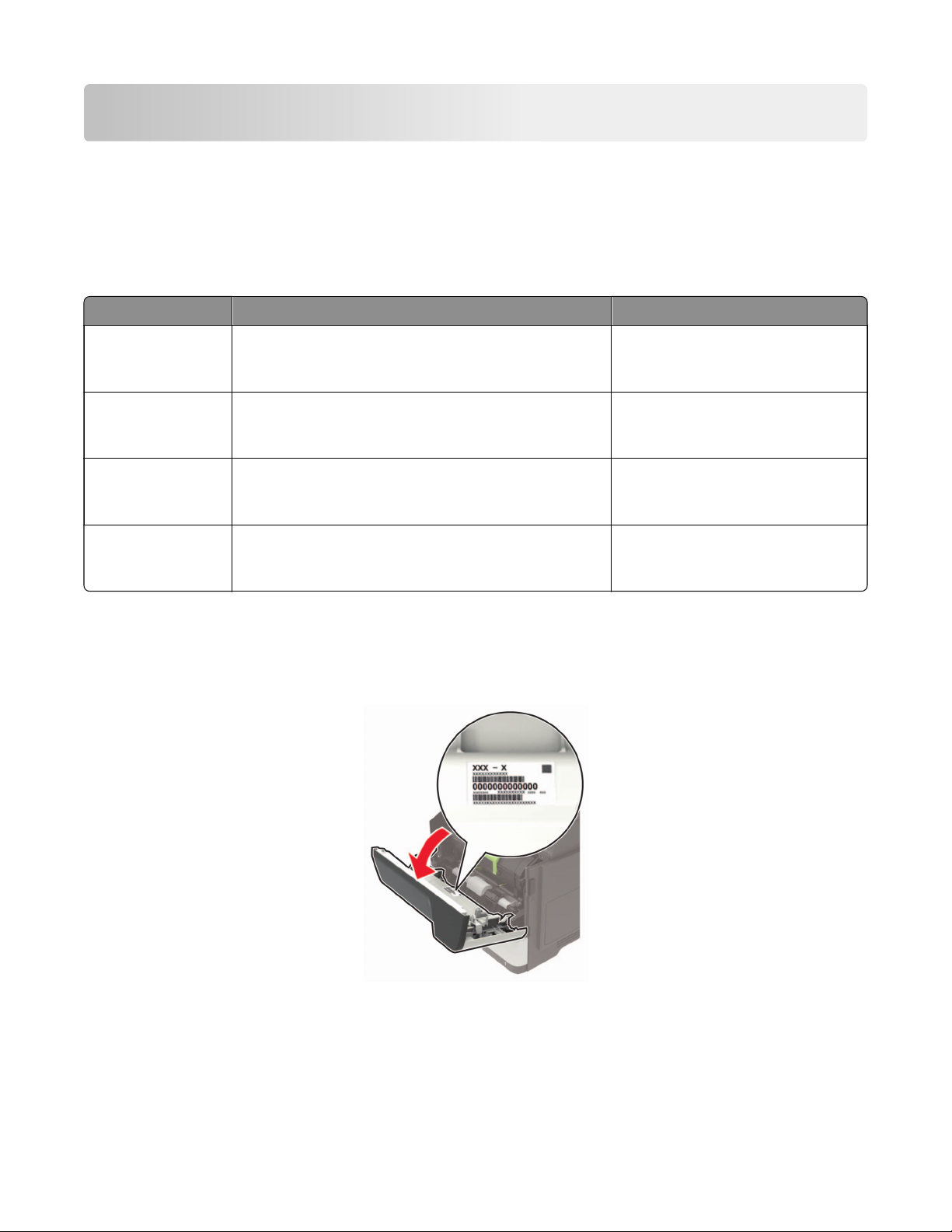
Finding the serial number
Open door A, and then
the serial number at the right side of the printer.
find
4600-835
4600-830
4600-830
4600‑895
General information
21
4600-830, -835, -895
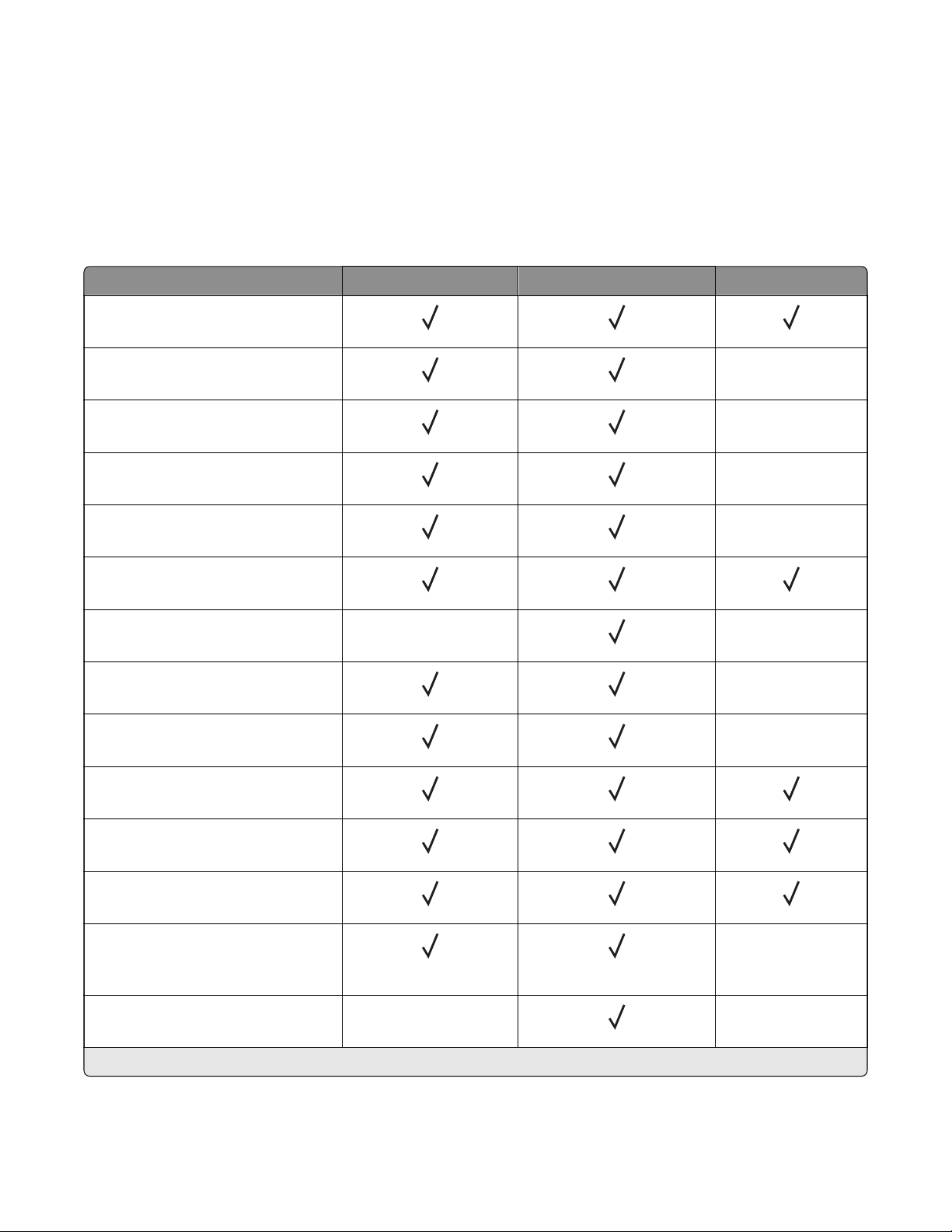
Paper support
The following tables provide information on standard and optional paper sources and the sizes, types, and
weights of paper they support.
Note: For an unlisted paper size, select the closest larger listed size.
Supported paper sizes
Paper size Tray Multipurpose feeder Two‑sided printing
A4
210 x 297 mm (8.3 x 11.7 in.)
A5
210 x 148 mm (5.8 x 8.3 in.)
A5 LEF*
148 x 210 mm (5.8 x 8.3 in.)
A6*
105 x 148 mm (4.1 x 5.8 in.)
JIS B5
182 x 257 mm (7.2 x 10.1 in.)
Oficio (Mexico)
216 x 340 mm (8.5 x 13.4 in.)
Hagaki
100 x 148 mm (3.9 x 5.8 in.)
Statement
140 x 216 mm (5.5 x 8.5 in.)
Executive
184 x 267 mm (7.3 x 10.5 in.)
Letter
216 x 279 mm (8.5 x 11 in.)
X
X
X
X
X
X
X
X
Legal
216 x 356 mm (8.5 x 14 in.)
Folio
216 x 330 mm (8.5 x 13 in.)
Universal
76.2 x 127 mm (3 x 5 in.) to
216 x 356 mm (8.5 x 14 in.)
7 3/4 Envelope (Monarch)
98 x 191 mm (3.9 x 7.5 in.)
* This paper size is not supported in the optional tray.
X
General information
X
X
22
4600-830, -835, -895
Paper size Tray Multipurpose feeder Two‑sided printing
9 Envelope
X
X
98 x 225 mm (3.9 x 8.9 in.)
10 Envelope
X
X
105 x 241 mm (4.1 x 9.5 in.)
DL Envelope
X
X
110 x 220 mm (4.3 x 8.7 in.)
C5 Envelope
X
X
162 x 229 mm (6.4 x 9 in.)
B5 Envelope
X
X
176 x 250 mm (6.9 x 9.8 in.)
Other Envelope
X
X
76.2 x 127 mm (3 x 5 in.) to
216 x 356 mm (8.5 x 14 in.)
* This paper size is not supported in the optional tray.
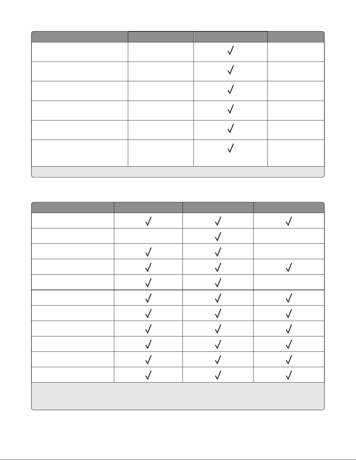
Supported paper types
Paper type Tray Multipurpose feeder Two‑sided printing
Plain paper
Card stock X X
Transparency
X
Recycled
Paper labels
2
Bond
1
X
Letterhead
Preprinted
Colored Paper
Light Paper
Heavy Paper
1
One‑sided paper labels designed for laser printers are supported for occasional use. It is recommended to print
2
20 or fewer pages of paper labels per month. Vinyl, pharmacy, and two‑sided labels are not supported.
2
Bond and Heavy Paper are supported in two‑sided printing up to 90‑g/m2 (24‑lb) paper weight.
General information
23

4600-830, -835, -895
Paper type Tray Multipurpose feeder Two‑sided printing
Rough/Cotton
Envelope X X
Rough envelope X
1
One‑sided paper labels designed for laser printers are supported for occasional use. It is recommended to print
20 or fewer pages of paper labels per month. Vinyl, pharmacy, and two‑sided labels are not supported.
2
Bond and Heavy Paper are supported in two‑sided printing up to 90‑g/m2 (24‑lb) paper weight.
X
Supported paper weights
Tray Multipurpose feeder Two‑sided printing
Paper weight
60–120 g/m
2
(16–32 lb) 60–216 g/m2 (16–58 lb) 60–90 g/m2 (16–24 lb)
Tools required for service
• Flat-blade screwdrivers, various sizes
• #1 Phillips screwdriver, magnetic
• #2 Phillips screwdriver, magnetic
• #2 Phillips screwdriver, magnetic short-blade
• Torx screwdriver (T20 head)
• Needle‑nose pliers
• Diagonal side cutters
• Spring hook
• Feeler gauges
• Analog or digital multimeter
• 3‑mm ball hex wrench
• Ton er vac uu m
• Flashlight
General information
24

4600-830, -835, -895
Diagnostics and troubleshooting
CAUTION—SHOCK HAZARD: This product uses a soft power switch. It does not physically disconnect
the input AC voltage. To avoid the risk of electrical shock, always remove the power cord from the
printer when removal of the input AC voltage is required.
CAUTION—SHOCK HAZARD: To avoid the risk of electrical shock and to prevent damage to the printer,
remove the power cord from the electrical outlet and disconnect all connections to any external devices
before you connect or disconnect any cable, electronic board, or assembly.
CAUTION—HOT SURFACE: The inside of the printer might be hot. To reduce the risk of injury from a hot
component, allow the surface to cool before touching it.
CAUTION—PINCH HAZARD: To avoid the risk of a pinch injury, use caution in areas marked with this
label. Pinch injuries may occur around moving parts, such as gears, doors, trays, and covers.
Troubleshooting overview
Performing the initial troubleshooting check
Before you start the troubleshooting procedures, perform the following checks:
• Use genuine Lexmark supplies and parts for the best results. Third-party supplies or parts may aect the
performance, reliability, or life of the printer and its imaging components.
• With the power cord unplugged from the electrical outlet, check that the cord is free from the breakage,
short circuits, disconnected wires, or incorrect connections.
• Make sure the printer is properly grounded. Check the power cord ground terminal.
• Make sure the power supply line voltage is within 10% of the rated line voltage.
• Make sure the machine is securely installed on a level surface in a well‑ventilated area.
• Make sure the room temperature is between 16 and 32°C (60 and 90°F) and that the relative humidity is
between 20 and 80%.
• Avoid sites generating ammonia gas, high temperature, high humidity (near water faucets, kettles,
humidifiers), cold spaces, near open flames, and dusty areas.
• Avoid sites exposed to direct sunlight.
• Make sure the paper is the recommended paper for this printer.
• Make a trial print with paper from a newly opened package, and check the result.
Fixing print quality issues
• “Initial print quality check” on page 26
• “Gray background or toner fog check” on page 27
Diagnostics and troubleshooting
25

4600-830, -835, -895
• “Blank pages check” on page 29
• “Print is too dark check” on page 35
• “Print is too light check” on page 37
• “Paper curl check” on page 40
• “Folded or wrinkled paper check” on page 41
• “Solid black pages check” on page 42
• “Repeating defects check” on page 45
• “Skewed print check” on page 46
• “Streaked vertical lines appear on prints check” on page 48
• “Horizontal light bands check” on page 49
• “Vertical light bands check” on page 50
• “Vertical dark bands check” on page 51
• “Vertical dark streaks with print missing check” on page 53
• “White streaks and voided areas check” on page 55
• “Fine lines are not printed correctly (specifically Chinese characters) check” on page 58
• “Clipped pages or images check” on page 59
• “Compressed images appear on prints check” on page 61
• “Incorrect margins on prints check” on page 62
• “Toner rubs o check” on page 63
• “Toner specks appear on prints check” on page 64
Initial print quality check
Before troubleshooting print problems, perform the following:
• Make sure that the printer is located in an area that follows the recommended operating environment
and power requirement specifications.
• Check the status of supplies. Replace supplies that are low or empty.
• Load 20‑lb (75-80 g/m
locked. From the control panel, set the paper size and type to match the paper loaded in the tray.
• From the control panel, navigate to Settings > Tro ublesh ooting > Print Quality Test Pages.
• Print and keep the Menu Settings Page. The original page is used to restore the custom settings if
necessary.
• On the Menu Settings page, check if the print resolution is set to 600 dpi and the toner darkness is set
to Normal.
• Check the toner cartridges for damage, and replace if necessary.
• Make sure that the correct print driver is used to prevent print problems. If the wrong print driver is
installed, then incorrect characters could print and the copy may not fit the page correctly.
2
) plain letter or A4 paper. Make sure that the paper guides are properly set and
Diagnostics and troubleshooting
26

4600-830, -835, -895
Gray background or toner fog check
Note: Before performing this print quality check, go to the control panel home screen and navigate to
Settings > Troubleshooting > Print Quality Test Pages, and then perform the Initial print quality check.
See
“Initial print quality check” on page 26.
Actions Yes No
Step 1
a Turn o the printer, wait for 10 seconds, and then turn on the
printer.
b From the control panel:
1 Increase the toner darkness in the Quality menu.
Note: 8 is the factory default setting.
2 Set the paper type, texture, and weight in the Paper menu
to match the paper loaded.
Does the problem remain?
Step 2
Check if the printer is using a genuine and supported Lexmark
toner cartridge.
Note: If the printer is using a third‑party cartridge, then refer the
users to their cartridge supplier.
Is the printer using a genuine and supported toner cartridge?
Step 3
Install a genuine and supported toner cartridge.
Does the problem remain?
Go to step 2. The problem is
solved.
Go to step 4. Go to step 3.
Go to step 4. The problem is
solved.
Diagnostics and troubleshooting
27
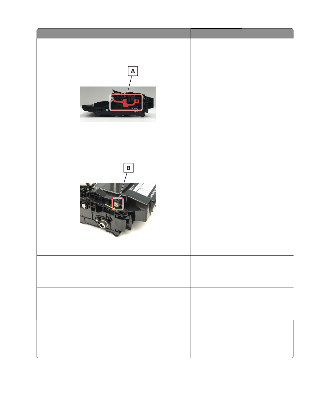
4600-830, -835, -895
Actions Yes No
Step 4
a Remove any packing material left on the imaging unit, including
the red separator plastic (A).
Note: You may need a pair of pliers to remove a piece of
broken plastic inside the imaging unit.
b Check the charge roller contact (B) on the right side of the
imaging unit for damage and contamination.
Go to step 5. Go to step 6.
Is the charge roller contact damaged and contaminated?
Step 5
Repair or replace the charge roller contact on the imaging unit.
Does the problem remain?
Step 6
Replace the imaging unit.
Does the problem remain?
Step 7
Make sure that connection JPS1 on the controller board and the
connections on the power supply are properly connected.
Are the connections properly connected?
Diagnostics and troubleshooting
28
Go to step 6. The problem is
solved.
Go to step 7. The problem is
solved.
Go to step 9. Go to step 8.
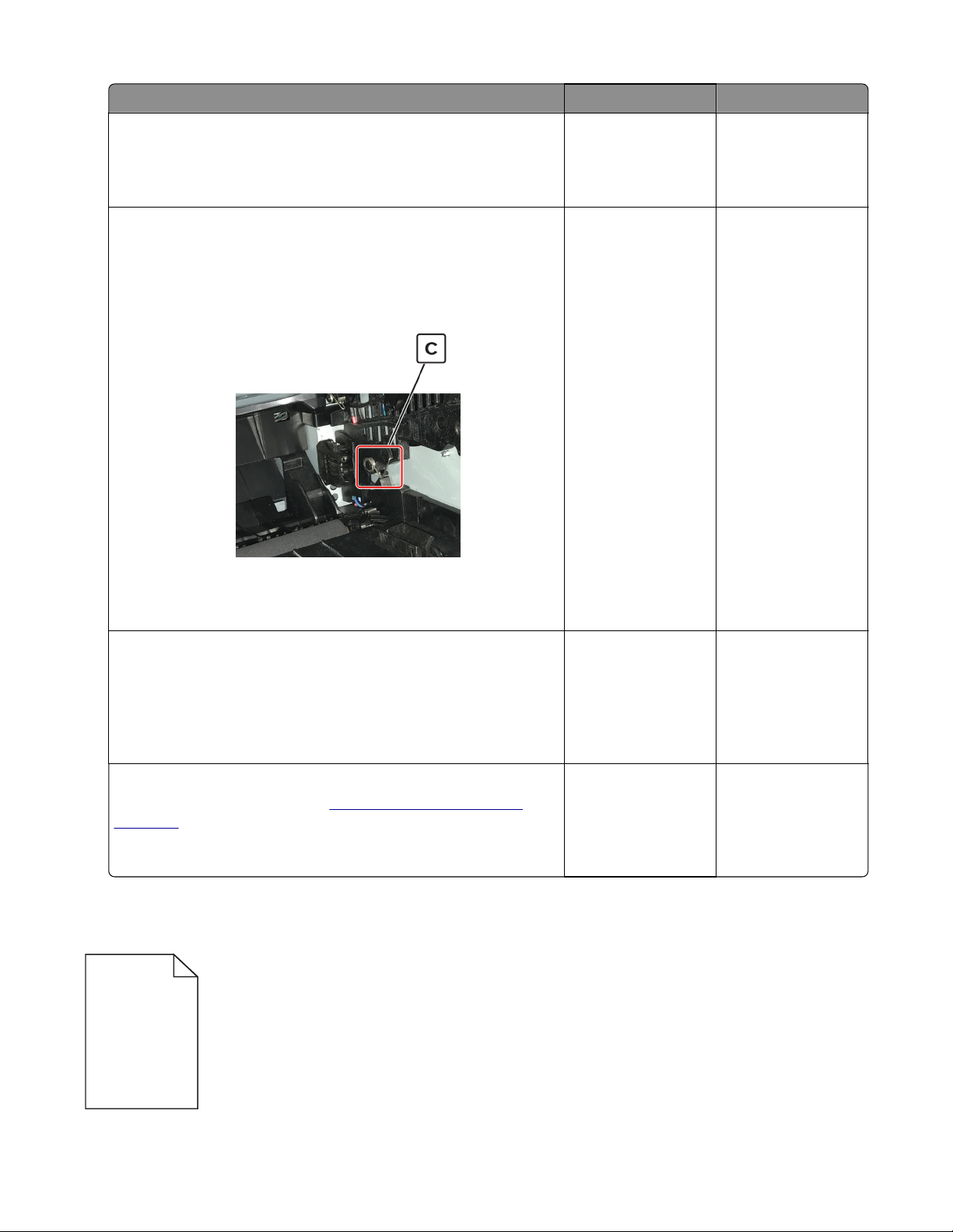
4600-830, -835, -895
Actions Yes No
Step 8
Reseat the connections.
Does the problem remain?
Step 9
Note: Poor electrical contact to the photoconductor is the most
likely source of a full page background defect.
a Remove any contamination from the photoconductor charge
contact (C) on the right side of the frame.
b Perform a print test.
Go to step 9. The problem is
solved.
Go to step 10. The problem is
solved.
Does the problem remain?
Step 10
Check if the photoconductor charge contact is bent, damaged, or
not in proper contact with the imaging unit.
Is the contact free from damage and in proper contact with the
imaging unit?
Step 11
Replace the power supply. See
page 216.
Does the problem remain?
“Power supply removal” on
Blank pages check
Go to step 11. Contact the next
level of support.
Contact the next
level of support.
The problem is
solved.
Diagnostics and troubleshooting
29

4600-830, -835, -895
Note: Before performing this print quality check, go to the control panel home screen and navigate to
Settings > Troubles hooting > Print Quality Test Pages, and then perform the Initial print quality check. See
“Initial print quality check” on page 26.
Actions Yes No
Step 1
Check if the printer is using a genuine and supported Lexmark
toner cartridge.
Note: If the printer is using a third‑party cartridge, then refer the
users to their cartridge supplier.
Is the printer using a genuine and supported toner cartridge?
Step 2
Install a genuine and supported toner cartridge.
Does the problem remain?
Step 3
a Check and remove any packing material left on the imaging
unit.
b Firmly shake the imaging unit to redistribute the toner, and then
reinstall it.
Does the problem remain?
Step 4
Check the imaging unit for damage and proper installation, and
replace if necessary.
Go to step 3. Go to step 2.
Go to step 3. The problem is
solved.
Go to step 4. The problem is
solved.
Go to step 5. The problem is
solved.
Does the problem remain?
Diagnostics and troubleshooting
30

4600-830, -835, -895
Actions Yes No
Step 5
Check the coupler to make sure that it is not stuck in the retracted
position. While slowly closing the door, observe the coupler to see
if it moves inward.
Note: With the imaging unit removed, the coupler should retract
with the door open and move inward when the front door is
closed.
Go to step 6. Go to step 7.
Is the coupler stuck, and not moving inward, while closing the front
door?
Diagnostics and troubleshooting
31

4600-830, -835, -895
Actions Yes No
Step 6
Reach inside the printer and manually reposition the coupler in the
direction of the red arrow as shown.
Does the problem remain?
Step 7
Check if the imaging unit contact (A) is bent, damaged, or not in
proper contact with the imaging unit.
Go to step 7. The problem is
solved.
Go to step 8. Contact the next
level of support.
Are the contacts free from damage, not bent and in proper contact
with the imaging unit?
Step 8
Check all connections in the power supply. If necessary, replace
the power supply.
Does the problem remain?
Step 9
Reseat cable JPS1 on the controller board.
Does the problem remain?
Diagnostics and troubleshooting
32
Go to step 9. The problem is
solved.
Go to step 10. The problem is
solved.

4600-830, -835, -895
Actions Yes No
Step 10
Replace the cable.
Does the problem remain?
Step 11
a Check the transfer roller for proper installation. If necessary,
remove and then reinstall the transfer roller.
b Check the transfer roller for contamination and damage.
Is the transfer roller free of contamination and damage?
Step 12
Replace the transfer roller. See
page 206.
Does the problem remain?
Step 13
Check the transfer roller left contact spring on the transfer roller
left arm for damage.
Is the contact spring free of damage?
“Transfer roller removal” on
Go to step 11. The problem is
solved.
Go to step 13. Go to step 12.
Go to step 13. The problem is
solved.
Go to step 15. Go to step 14.
Step 14
Replace the transfer roller left arm with cable.
Does the problem remain?
Go to step 15. The problem is
solved.
Diagnostics and troubleshooting
33

4600-830, -835, -895
Actions Yes No
Step 15
a Check the coupler for signs of damage. The coupler is located
on the main drive motor.
• Good condition
• Bad condition
Go to step 16. The problem is
solved.
b If the coupler is damaged, then replace the main drive motor.
Does the problem remain?
Step 16
Reseat the printhead cables on the controller board.
Does the problem remain?
Step 17
Replace the laser printhead. See
page 239.
Does the problem remain?
“Printhead removal” on
Diagnostics and troubleshooting
34
Go to step 17. The problem is
solved.
Contact the next
level of support.
The problem is
solved.

4600-830, -835, -895
Print is too dark check
Note: Before performing this print quality check, go to the control panel home screen and navigate to
Settings > Troubleshooting > Print Quality Test Pages, and then perform the Initial print quality check.
See
“Initial print quality check” on page 26.
Actions Yes No
Step 1
Check if the printer is using a genuine and supported Lexmark
toner cartridge.
Note: If the printer is using a third‑party cartridge, then refer the
users to their cartridge supplier.
Is the printer using a genuine and supported toner cartridge?
Step 2
Install a genuine and supported toner cartridge.
Does the problem remain?
Step 3
a Turn o the printer, wait for 10 seconds, and then turn on the
printer.
b From the control panel, reduce the toner darkness in the
Quality menu.
Note: 8 is the factory default setting.
Does the problem remain?
Step 4
From the control panel, set the paper type, texture, and weight in
the Paper menu to match the paper loaded.
Go to step 3. Go to step 2.
Go to step 3. The problem is
solved.
Go to step 4. The problem is
solved.
Go to step 5. The problem is
solved.
Does the problem remain?
Step 5
Depending on the operating system, specify the paper type,
texture, and weight from Printing Preferences or Print dialog.
Does the problem remain?
Diagnostics and troubleshooting
35
Go to step 6. The problem is
solved.

4600-830, -835, -895
Actions Yes No
Step 6
a Check if the paper loaded has texture or rough finishes.
b From the control panel, set the paper texture in the Paper menu
to match the texture of the paper loaded.
Does the problem remain?
Step 7
Make sure that the paper loaded is from a fresh package.
Note: Paper absorbs moisture due to high humidity. Store paper
in its original wrapper until you use it.
Does the problem remain?
Step 8
Replace the imaging unit.
Does the problem remain?
Step 9
Check if the imaging unit contacts (A) are bent, damaged, or not in
proper contact with the imaging unit.
Go to step 7. The problem is
solved.
Go to step 8. The problem is
solved.
Go to step 9. The problem is
solved.
Go to step 10. Contact the next
level of support.
Are the contacts free from damage, not bent and in proper contact
with the imaging unit?
Step 10
Check all connections on the power supply for proper connection.
Is the power supply properly connected?
Step 11
Replace the connections.
Does the problem remain?
Diagnostics and troubleshooting
36
Contact the next
level of support.
Go to step 12. The problem is
Go to step 11.
solved.

4600-830, -835, -895
Actions Yes No
Step 12
Replace the power supply. See
page 216.
Does the problem remain?
“Power supply removal” on
Contact the next
level of support.
The problem is
solved.
Print is too light check
Note: Before performing this print quality check, go to the control panel home screen and navigate to
Settings > Troubleshooting > Print Quality Test Pages, and then perform the Initial print quality check.
See
“Initial print quality check” on page 26.
Actions Yes No
Step 1
Check if the printer is using a genuine and supported Lexmark
toner cartridge.
Note: If the printer is using a third‑party cartridge, then refer the
users to their cartridge supplier.
Is the printer using a genuine and supported toner cartridge?
Step 2
Install a genuine and supported toner cartridge.
Does the problem remain?
Step 3
a Turn o the printer, wait for 10 seconds, and then turn on the
printer.
b From the control panel:
1 Increase the toner darkness in the Quality menu.
Note: 8 is the factory default setting.
2 Set the paper type, texture, and weight in the Paper menu
to match the paper loaded.
Does the problem remain?
Go to step 3. Go to step 2.
Go to step 3. The problem is
solved.
Go to step 4. The problem is
solved.
Diagnostics and troubleshooting
37

4600-830, -835, -895
Actions Yes No
Step 4
a Remove the toner cartridge and imaging unit.
b Push either side of the transfer roller , located below the
imaging unit, to check if it depresses and bounces back into
place.
c If the transfer roller does not depress and bounce back into
place, then reinstall it by pulling up the blue gear and pulling it
out from the right side to the left.
d Firmly shake the imaging unit to redistribute the toner, and then
reinstall it.
e Reinstall the toner cartridge.
f Turn o the printer, wait for 10 seconds, and then turn on the
printer.
Does the problem remain?
Step 5
Check the shutter on the imaging unit for signs of damage.
Note: The shutter opens to receive toner from the toner
cartridge.
Is the shutter on the imaging unit working properly?
Go to step 5. The problem is
solved.
Go to step 6. Go to step 7.
Step 6
a Check the status of the imaging unit.
1 From the home screen, select Status/supplies.
2 Select View Supplies.
b Check the condition of the imaging unit.
Is the imaging unit near end of life and/or showing signs toner
leakage?
Step 7
Replace the imaging unit.
Does the problem remain?
Step 8
Replace the transfer roller. See
page 206.
Does the problem remain?
“Transfer roller removal” on
Go to step 7. Go to step 8.
Go to step 8. The problem is
solved.
Go to step 9. The problem is
solved.
Diagnostics and troubleshooting
38

4600-830, -835, -895
Actions Yes No
Step 9
Clean the printhead lens. See
page 257.
Note: This is applicable only to models installed with a galvo
LSU. To determine whether the LSU is galvo, check the serial
number of the printer. The sixth digit character assigned should
be in the 0–9 or B–N range (Example: 4514 20HH 007CR).
Does the problem remain?
Step 10
Replace the power supply. See
page 216.
Does the problem remain?
Step 11
Check the cartridge gearbox for damage.
Is the cartridge gearbox free from damage?
Step 12
Replace the cartridge gearbox. See
on page 184.
“Cleaning the printhead lenses” on
“Power supply removal” on
“Cartridge gearbox removal”
Go to step 10. The problem is
solved.
Go to step 11. The problem is
solved.
Go to step 13. Go to step 12.
Go to step 13. The problem is
solved.
Does the problem remain?
Step 13
Check connection JCART1 on the controller board and the
connection on the cartridge gearbox.
Are the connections properly connected?
Step 14
Replace the connections.
Does the problem remain?
Step 15
Replace the cartridge gearbox. See
on page 184.
Does the problem remain?
Step 16
Replace the controller board. See
page 194.
Does the problem remain?
“Cartridge gearbox removal”
“Controller board removal” on
Go to step 15. Go to step 14.
Go to step 15. The problem is
solved.
Go to step 16. The problem is
solved.
Contact the next
level of support.
The problem is
solved.
Diagnostics and troubleshooting
39

4600-830, -835, -895
Paper curl check
Note: Before performing this print quality check, go to the control panel home screen and navigate to
Settings > Troubleshooting > Print Quality Test Pages, and then perform the Initial print quality check.
See
“Initial print quality check” on page 26.
Actions Yes No
Step 1
Check if the printer is using a genuine and supported Lexmark
toner cartridge.
Note: If the printer is using a third‑party cartridge, then refer the
users to their cartridge supplier.
Is the printer using a genuine and supported toner cartridge?
Step 2
Install a genuine and supported toner cartridge.
Does the problem remain?
Step 3
Adjust the guides in the tray to the correct position for the paper
loaded.
Does the problem remain?
Step 4
From the control panel, set the paper size, type, and weight in the
Paper menu to match the paper loaded.
Does the problem remain?
Go to step 3. Go to step 2.
Go to step 3. The problem is
solved.
Go to step 4. The problem is
solved.
Go to step 5. The problem is
solved.
Step 5
Depending on the operating system, specify the paper size from
Printing Preferences or Print dialog.
Does the problem remain?
Step 6
Remove paper from the tray, and then turn it over.
Does the problem remain?
Diagnostics and troubleshooting
40
Go to step 6. The problem is
solved.
Go to step 7. The problem is
solved.

4600-830, -835, -895
Actions Yes No
Step 7
Make sure that the paper loaded is from a fresh package.
Note: Paper absorbs moisture due to high humidity. Store paper
in its original wrapper until you use it.
Does the problem remain?
Step 8
Make sure that the printer supports the paper loaded.
Is the paper supported?
Step 9
Load a supported paper.
Does the problem remain?
Folded or wrinkled paper check
Go to step 8. The problem is
solved.
Contact the next
level of support.
Contact the next
level of support.
Go to step 9.
The problem is
solved.
Note: Before performing this print quality check, go to the control panel home screen and navigate to
Settings > Troubleshooting > Print Quality Test Pages, and then perform the Initial print quality check.
See
“Initial print quality check” on page 26.
Actions Yes No
Step 1
a Check if the printer is using a non-Lexmark toner cartridge.
Note: If the printer is using a third‑party cartridge, then do not
replace the imaging unit. Refer the users to their cartridge
supplier.
Go to step 2. The problem is
solved.
b Make sure that the toner cartridge is compatible with the
imaging unit.
Does the problem remain?
Diagnostics and troubleshooting
41

4600-830, -835, -895
Actions Yes No
Step 2
a Check if the paper loaded is from a fresh package.
Note: The amount of moisture in paper
quality and printer ability to feed paper correctly.
aects
both print
b Make sure that the printer supports the paper loaded. For a
complete list of supported paper, see the printer User's Guide.
Does the problem remain?
Step 3
Make sure that the fuser entry guide is free of waste toner and dust.
Warning—Potential Damage: Clean the fuser entry guide with a
toner vacuum and cloth. Do not use compressed air.
Does the problem remain?
Step 4
If the fuser has reached end of life, then replace the maintenance
kit.
Does the problem remain?
Go to step 3. The problem is
solved.
Go to step 4. The problem is
solved.
Contact the next
level of support.
The problem is
solved.
Solid black pages check
Note: Before performing this print quality check, go to the control panel home screen and navigate to
Settings > Troubleshooting > Print Quality Test Pages, and then perform the Initial print quality check.
See
“Initial print quality check” on page 26.
Diagnostics and troubleshooting
42

4600-830, -835, -895
Actions Yes No
Step 1
Check if the printer is using a genuine and supported Lexmark
toner cartridge.
Note: If the printer is using a third‑party cartridge, then refer the
users to their cartridge supplier.
Is the printer using a genuine and supported toner cartridge?
Step 2
Install a genuine and supported toner cartridge.
Does the problem remain?
Step 3
a Remove any packing material left on the imaging unit, including
the red separator plastic (A).
Go to step 3. Go to step 2.
Go to step 3. The problem is
solved.
Go to step 4. Go to step 5.
Note: You may need a pair of pliers to remove a piece of
broken plastic inside the imaging unit.
b Check the charge roller contact (B) on the right side of the
imaging unit for damage and contamination.
Is the charge roller contact damaged and contaminated?
Step 4
Repair or replace the charge roller contact on the imaging unit.
Does the problem remain?
Go to step 5. The problem is
solved.
Diagnostics and troubleshooting
43

4600-830, -835, -895
Actions Yes No
Step 5
Replace the imaging unit.
Does the problem remain?
Step 6
Check if the imaging unit contact (C) is contaminated, broken, or
bent out of proper position.
Is the contact contaminated, broken, or bent out of proper
position?
Go to step 6. The problem is
solved.
Go to step 7. Go to step 8.
Step 7
Clean or repair the imaging unit contacts.
Does the problem remain?
Step 8
Check the high voltage metal contacts on the imaging unit for
damage. If necessary, replace the imaging unit.
Does the problem remain?
Step 9
Check cable JPS1 from the controller board to the power supply
for proper connection.
Is the cable properly connected?
Step 10
Reseat the cable.
Does the problem remain?
Step 11
Replace the cable.
Contact the next
level of support.
Go to step 9. The problem is
Go to step 11. Go to step 10.
Go to step 11. The problem is
Contact the next
level of support.
The problem is
solved.
solved.
solved.
The problem is
solved.
Does the problem remain?
Diagnostics and troubleshooting
44

4600-830, -835, -895
Repeating defects check
Note: Before performing this print quality check, go to the control panel home screen and navigate to
Settings > Troubles hooting > Print Quality Test Pages, and then perform the Initial print quality check. See
“Initial print quality check” on page 26.
Actions Yes No
Step 1
Using the Print Quality Test Pages, check if the distance between
the repeating defects is equal to any of the following:
• 97 mm (3.82 in.)
• 47 mm (1.85 in.)
• 38 mm (1.5 in.)
Does the distance between the repeating defects match any of the
measurements?
Step 2
Replace the imaging unit.
Does the problem remain?
Step 3
Check if the distance between repeating defects is equal to 3.15
inches (85 mm).
Does the distance between repeating defects equal to 3.15 inches
(85 mm)?
Step 4
Replace the fuser. See
“Fuser removal” on page 234.
Go to step 2. Go to step 3.
Go to step 3. The problem is
solved.
Go to step 4. Contact the next
level of support.
Go to step 5. The problem is
solved.
Does the problem remain?
Step 5
Replace the transfer roller. See
page 206.
Does the problem remain?
“Transfer roller removal” on
Diagnostics and troubleshooting
45
Contact the next
level of support.
The problem is
solved.

4600-830, -835, -895
Skewed print check
Note: Before performing this print quality check, go to the control panel home screen and navigate to
Settings > Troubleshooting > Print Quality Test Pages, and then perform the Initial print quality check.
See
“Initial print quality check” on page 26.
Actions Yes No
Step 1
Check the guides in the tray where the skewed prints are sourced
from.
Note: If paper is sourced from the MPF, then proceed to
Does the position of the guides match the paper loaded?
Step 2
Adjust the guides to match the paper loaded.
Does the problem remain?
Step 3
Check if the printer supports the paper loaded.
Note: For a complete list of supported paper, see the printer
User’s Guide.
Is the paper supported?
Step 4
Remove the paper, and then load a supported one.
Does the problem remain?
step 9.
Go to step 3. Go to step 2.
Go to step 3. The problem is
solved.
Go to step 5. Go to step 4.
Go to step 5. The problem is
solved.
Step 5
Check the tray pick roller for excess wear and contamination.
Is the pick roller free from excess wear and contamination?
Step 6
Replace the pick roller. See
page 230.
Does the problem remain?
“Pick roller assembly removal” on
Diagnostics and troubleshooting
46
Go to step 7. Go to step 6.
Go to step 7. The problem is
solved.

4600-830, -835, -895
Actions Yes No
Step 7
Perform a print test.
From the Diagnostics menu, select PRINT TESTS > Tray [x].
Note: [x] refers to the tray where the skewed prints are sourced
from.
Does the problem remain?
Step 8
Adjust the margins.
From the Diagnostic menu, select REGISTRATION.
Does the problem remain?
Step 9
Check the guides in the MPF tray.
Does the position of the guides match the paper loaded?
Step 10
Adjust the guides to match the paper loaded.
Does the problem remain?
Go to step 8. The problem is
solved.
Go to step 15. The problem is
solved.
Go to step 11. Go to step 10.
Go to step 11. The problem is
solved.
Step 11
Check if the printer supports the paper loaded.
Note: For a complete list of supported paper, see the printer
User’s Guide.
Is the paper supported?
Step 12
Remove the paper, and then load a supported one.
Does the problem remain?
Step 13
Check the MPF pick roller for excess wear and contamination.
Is the MPF pick roller free from excess wear and contamination?
Step 14
Replace the MPF pick roller. See
pad removal” on page 209.
Does the problem remain?
“MPF pick roller and separator
Go to step 13. Go to step 12.
Go to step 13. The problem is
solved.
Go to step 15. Go to step 14.
Go to step 15. The problem is
solved.
Diagnostics and troubleshooting
47

4600-830, -835, -895
Actions Yes No
Step 15
Perform the paper skew adjustment. See
adjustment” on page 175.
Does the problem remain?
“Printhead assembly
Contact the next
level of support.
The problem is
solved.
Streaked vertical lines appear on prints check
Note: Before performing this print quality check, go to the control panel home screen and navigate to
Settings > Troubles hooting > Print Quality Test Pages, and then perform the Initial print quality check. See
“Initial print quality check” on page 26.
Actions Yes No
Step 1
Check if the printer is using a genuine and supported Lexmark
toner cartridge.
Note: If the printer is using a third‑party cartridge, then refer the
users to their cartridge supplier.
Is the printer using a genuine and supported toner cartridge?
Step 2
Install a genuine and supported toner cartridge.
Does the problem remain?
Step 3
Remove, and then reinstall the imaging unit.
Does the problem remain?
Step 4
Replace the imaging unit.
Does the problem remain?
Go to step 3. Go to step 2.
Go to step 3. The problem is
solved.
Go to step 4. The problem is
solved.
Go to step 5. The problem is
solved.
Diagnostics and troubleshooting
48

4600-830, -835, -895
Actions Yes No
Step 5
Remove the fuser, and check for damage or debris on the rollers
and belts.
Are the rollers and belts free of damage or debris?
Step 6
Replace the fuser.
Does the problem remain?
Contact the next
level of support.
Contact the next
level of support.
Go to step 6.
The problem is
solved.
Horizontal light bands check
Note: Before performing this print quality check, go to the control panel home screen and navigate to
Settings > Troubleshooting > Print Quality Test Pages, and then perform the Initial print quality check.
See
“Initial print quality check” on page 26.
Actions Yes No
Step 1
Check if the printer is using a genuine and supported Lexmark
toner cartridge.
Note: If the printer is using a third‑party cartridge, then refer the
users to their cartridge supplier.
Is the printer using a genuine and supported toner cartridge?
Step 2
Install a genuine and supported toner cartridge.
Does the problem remain?
Step 3
Turn o the printer, wait for 10 seconds, and then turn on the printer.
Does the problem remain?
Go to step 3. Go to step 2.
Go to step 3. The problem is
solved.
Go to step 4. The problem is
solved.
Diagnostics and troubleshooting
49

4600-830, -835, -895
Actions Yes No
Step 4
Check the imaging unit contact block (A), including the white and
red wires, for damage or improper installation.
Is the imaging unit contact block free of damage and properly
installed?
Step 5
Replace the power supply. See
page 216.
“Power supply removal” on
Go to step 5. Contact the next
level of support.
Contact the next
level of support.
The problem is
solved.
Does the problem remain?
Vertical light bands check
Note: Before performing this print quality check, go to the control panel home screen and navigate to
Settings > Troubles hooting > Print Quality Test Pages, and then perform the Initial print quality check. See
“Initial print quality check” on page 26.
Diagnostics and troubleshooting
50

4600-830, -835, -895
Actions Yes No
Step 1
Check if the printer is using a genuine and supported Lexmark
toner cartridge.
Note: If the printer is using a third‑party cartridge, refer the users
to their cartridge supplier.
Is the printer using a genuine and supported toner cartridge?
Step 2
Install a genuine and supported toner cartridge.
Does the problem remain?
Step 3
Clean the printhead lens. See
page 257.
Note: This is applicable only to models installed with a galvo
LSU. To determine whether the LSU is galvo, check the serial
number of the printer. The sixth digit character assigned should
be in the 0–9 or B–N range (Example: 4514 20HH 007CR).
Does the problem remain?
Step 4
Replace the printhead. See
“Cleaning the printhead lenses” on
“Printhead removal” on page 239.
Go to step 3. Go to step 2.
Go to step 3. The problem is
solved.
Go to step 4. The problem is
solved.
Go to step 5. The problem is
solved.
Does the problem remain?
Step 5
Replace the imaging unit.
Does the problem remain?
Contact the next
level of support.
The problem is
solved.
Vertical dark bands check
Note: Before performing this print quality check, go to the control panel home screen and navigate to
Settings > Troubleshooting > Print Quality Test Pages, and then perform the Initial print quality check.
See
“Initial print quality check” on page 26.
Diagnostics and troubleshooting
51

4600-830, -835, -895
Actions Yes No
Step 1
Check if the printer is using a genuine and supported Lexmark
toner cartridge.
Note: If the printer is using a third‑party cartridge, then refer the
users to their cartridge supplier.
Is the printer using a genuine and supported toner cartridge?
Step 2
Install a genuine and supported toner cartridge.
Does the problem remain?
Step 3
Remove, and then reinstall the toner cartridge and imaging unit.
Does the problem remain?
Step 4
If a bright light enters the right side of the printer, then move the
printer to avoid the bright light.
Note: In cases where the printer cannot be moved or relocated,
add a cover to the fan inlet vent to block the light from entering
the printer, or contact the next level of support.
Go to step 3. Go to step 2.
Go to step 3. The problem is
solved.
Go to step 4. The problem is
solved.
Go to step 5. The problem is
solved.
Does the problem remain?
Step 5
If a separator plastic (A) is stuck inside the imaging unit or if there
are other obstructions between the charge roller and
photoconductor drum, then remove them.
Does the problem remain?
Contact the next
level of support.
The problem is
solved.
Diagnostics and troubleshooting
52

4600-830, -835, -895
Vertical dark streaks with print missing check
Note: Before performing this print quality check, go to the control panel home screen and navigate to
Settings > Troubleshooting > Print Quality Test Pages, and then perform the Initial print quality check.
See
“Initial print quality check” on page 26.
Actions Yes No
Step 1
Check if the printer is using a genuine and supported Lexmark
toner cartridge.
Note: If the printer is using a third‑party cartridge, then refer the
users to their cartridge supplier.
Is the printer using a genuine and supported toner cartridge?
Step 2
Install a genuine and supported toner cartridge.
Does the problem remain?
Go to step 3. Go to step 2.
Go to step 3. The problem is
solved.
Diagnostics and troubleshooting
53

4600-830, -835, -895
Actions Yes No
Step 3
a Remove any packing material left on the imaging unit, including
the red separator plastic (A).
Note: You may need a pair of pliers to remove a piece of
broken plastic inside the imaging unit.
b Check the charge roller contact (B) on the right side of the
imaging unit for damage and proper installation.
Go to step 4. Go to step 5.
Is the charge roller contact damaged and contaminated?
Step 4
Repair or replace the charge roller contact on the imaging unit.
Does the problem remain?
Step 5
Replace the imaging unit.
Does the problem remain?
Diagnostics and troubleshooting
54
Go to step 5. The problem is
solved.
Go to step 6. The problem is
solved.

4600-830, -835, -895
Actions Yes No
Step 6
Check if the imaging unit contacts (C) are contaminated or bent out
of proper position.
Are the contacts contaminated and bent out of proper position?
Step 7
Clean or repair the imaging unit contacts.
Does the problem remain?
Go to step 7. Go to step 8.
Go to step 8. The problem is
solved.
Step 8
Check connection JPS1 on the controller board and the
connections on the power supply.
Are the connections properly connected?
Step 9
Reconnect the cables.
Does the problem remain?
Step 10
Replace the power supply. See
page 216.
Does the problem remain?
“Power supply removal” on
White streaks and voided areas check
Go to step 10. Go to step 9.
Go to step 10. The problem is
solved.
Contact the next
level of support.
The problem is
solved.
Diagnostics and troubleshooting
55

4600-830, -835, -895
Note: Before performing this print quality check, go to the control panel home screen and navigate to
Settings > Troubleshooting > Print Quality Test Pages, and then perform the Initial print quality check.
See
“Initial print quality check” on page 26.
Actions Yes No
Step 1
Check if the printer is using a genuine and supported Lexmark
toner cartridge.
Note: If the printer is using a third‑party cartridge, do not replace
the imaging unit. Refer the users to their cartridge supplier.
Is the printer using a genuine and supported toner cartridge?
Step 2
Install a genuine and supported toner cartridge.
Does the problem remain?
Step 3
Set the paper type and weight settings in the Paper menu to match
the paper loaded.
Note: Make sure that the printer supports the paper loaded. For
a complete list of supported paper, see the printer User’s Guide.
Does the problem remain?
Step 4
a Update the firmware to the latest version available.
b Enter the Diagnostics menu, and then change the EngSetting
14 value to 48.
Note: You can also change the setting through a bundle
or NPA command.
file
c Set Quite mode to O.
d Review the Event Log Summary sheets and check if either error
code 31.46 or 31.66 events occurred for the imaging unit. If they
did, check if they are occurring with the current toner cartridge.
Go to step 3. Go to step 2.
Go to step 3. The problem is
solved.
Go to step 4. The problem is
solved.
Go to step 5. The problem is
solved.
Does the problem remain?
Diagnostics and troubleshooting
56

4600-830, -835, -895
Actions Yes No
Step 5
Check the shutter tab (A) on the toner cartridge for signs of
damage.
Is the shutter tab damaged?
Step 6
Replace the imaging unit and the toner cartridge.
Does the problem remain?
Go to step 6. Go to step 7.
Go to step 7. The problem is
solved.
Step 7
Clean the printhead lens. See
page 257.
Note: This is applicable only to models installed with a galvo
LSU. To determine whether the LSU is galvo, check the serial
number of the printer. The sixth digit character assigned should
be in the 0–9 or B–N range (Example: 4514 20HH 007CR).
Does the problem remain?
Step 8
Check if the imaging unit contacts (B) are contaminated or bent out
of proper position.
“Cleaning the printhead lenses” on
Go to step 8. The problem is
solved.
Go to step 9. Go to step 10.
Are the contacts contaminated or bent out of proper position?
Diagnostics and troubleshooting
57

4600-830, -835, -895
Actions Yes No
Step 9
Clean or repair the imaging unit contacts.
Does the problem remain?
Step 10
Check connection JPS1 on the controller board and all the
connections on the power supply.
Are the connections properly connected?
Step 11
Replace the connections.
Does the problem remain?
Step 12
Replace the power supply. See
page 216.
Does the problem remain?
Step 13
Replace the printhead. See
“Power supply removal” on
“Printhead removal” on page 239.
Contact the next
level of support.
Go to step 12. Go to step 11.
Go to step 12. The problem is
Go to step 13. The problem is
Contact the next
level of support.
The problem is
solved.
solved.
solved.
The problem is
solved.
Does the problem remain?
Fine lines are not printed correctly (specifically Chinese characters) check
Note: Before performing this print quality check, go to the control panel home screen and navigate to
Settings > Troubleshooting > Print Quality Test Pages, and then perform the Initial print quality check.
See
“Initial print quality check” on page 26.
Diagnostics and troubleshooting
58

4600-830, -835, -895
Actions Yes No
Step 1
Check if the printer is using a genuine and supported Lexmark
toner cartridge.
Note: If the printer is using a third‑party cartridge, then refer the
users to their cartridge supplier.
Is the printer using a genuine and supported toner cartridge?
Step 2
Install a genuine and supported toner cartridge.
Does the problem remain?
Step 3
From the control panel, adjust the Toner Darkness setting to 7.
a From the Settings menu, navigate to:
Print Settings > Quality menu > Pixel Boost > Fonts >
Submit
b From the Quality menu, select Toner Darkness, and then adjust
the setting to 7.
c Submit the changes.
Note: Adjusting the Toner Darkness setting to 7 results in a
slightly lighter print. You may leave the Toner Darkness value at 8
in order to maintain the darkness that you have grown
accustomed to, but this will result in reduced toner yield.
Go to step 3. Go to step 2.
Go to step 3. The problem is
solved.
Contact the next
level of support.
The problem is
solved.
Does the problem remain?
Clipped pages or images check
Note: Before performing this print quality check, go to the control panel home screen and navigate to
Settings > Troubles hooting > Print Quality Test Pages, and then perform the Initial print quality check. See
“Initial print quality check” on page 26.
Diagnostics and troubleshooting
59

4600-830, -835, -895
Actions Yes No
Step 1
Check if the printer is using a genuine and supported Lexmark
toner cartridge.
Note: If the printer is using a third‑party cartridge, then refer the
users to their cartridge supplier.
Is the printer using a genuine and supported toner cartridge?
Step 2
Install a genuine and supported toner cartridge.
Does the problem remain?
Step 3
Remove, and then reinstall the imaging unit.
Does the problem remain?
Step 4
Check if a separator plastic (A), or a piece of it, is stuck inside the
imaging unit or if there are any other obstructions between the
charge roller and photoconductor drum.
Go to step 3. Go to step 2.
Go to step 3. The problem is
solved.
Go to step 4. The problem is
solved.
Go to step 6. Go to step 5.
Is the imaging unit free from any separator plastic fragments or
other obstructions?
Step 5
Using a pair of pliers, remove the separator plastic fragments and
other obstructions.
Does the problem remain?
Step 6
Replace the imaging unit.
Does the problem remain?
Diagnostics and troubleshooting
60
Go to step 6. The problem is
solved.
Go to step 7. The problem is
solved.

4600-830, -835, -895
Actions Yes No
Step 7
Check the imaging unit contact block (B) for damage or improper
installation.
Is the imaging unit contact block damaged or improperly installed?
Step 8
Reinstall or replace the imaging unit contact block.
Does the problem remain?
Go to step 8. Contact the next
level of support.
Contact the next
level of support.
The problem is
solved.
Compressed images appear on prints check
Note: Before performing this print quality check, go to the control panel home screen and navigate to
Settings > Troubleshooting > Print Quality Test Pages, and then perform the Initial print quality check.
See
“Initial print quality check” on page 26.
Diagnostics and troubleshooting
61

4600-830, -835, -895
Actions Yes No
Step 1
Remove the imaging unit, and then inspect the white
photoconductor coupler (A). The coupler should be firmly
connected to the imaging unit and should not freely rotate.
Does the coupler move freely or appear damaged?
Step 2
Replace the imaging unit.
Does the problem remain?
Step 3
Replace the main drive gearbox. See
removal” on page 178.
“Main drive gearbox
Go to step 2. Go to step 3.
Go to step 3. The problem is
solved.
Contact the next
level of support.
The problem is
solved.
Does the problem remain?
Incorrect margins on prints check
Note: Before performing this print quality check, go to the control panel home screen and navigate to
Settings > Troubleshooting > Print Quality Test Pages, and then perform the Initial print quality check.
See
“Initial print quality check” on page 26.
Diagnostics and troubleshooting
62

4600-830, -835, -895
Actions Yes No
Step 1
Adjust the guides in the tray according to the size of the paper
loaded.
Does the problem remain?
Step 2
Do one of the following:
• From the printer control panel, set the paper size in the Paper
menu to match the paper loaded in the tray.
• Change the paper loaded in the tray to match the paper size
specified in the tray settings.
Does the problem remain?
Step 3
Depending on your operating system, specify the paper size from
Printing Preferences or from the Print dialog.
Does the problem remain?
Step 4
a Enter the Diagnostics menu, and then select Registration.
b Adjust the margins as necessary.
Go to step 2. The problem is
solved.
Go to step 3. The problem is
solved.
Go to step 4 or
contact the next
level of support.
Contact the next
level of support.
The problem is
solved.
The problem is
solved.
Does the problem remain?
Toner rubs o check
Note: Before performing this print quality check, go to the control panel home screen and navigate to
Settings > Troubles hooting > Print Quality Test Pages, and then perform the Initial print quality check. See
“Initial print quality check” on page 26.
Diagnostics and troubleshooting
63

4600-830, -835, -895
Actions Yes No
Step 1
Check if the printer is using a genuine and supported Lexmark
toner cartridge.
Note: If the printer is using a third‑party cartridge, then refer the
users to their cartridge supplier.
Is the printer using a genuine and supported toner cartridge?
Step 2
Install a genuine and supported toner cartridge.
Does the problem remain?
Step 3
From the control panel, set the paper type, texture, and weight in
the Paper menu to match the paper loaded.
Does the problem remain?
Step 4
Remove, and then reinstall the fuser.
Does the problem remain?
Go to step 3. Go to step 2.
Go to step 3. The problem is
solved.
Go to step 4. The problem is
solved.
Go to step 5. The problem is
solved.
Step 5
Replace the fuser. See
Does the problem remain?
Step 6
Reseat the connections on the power supply.
Does the problem remain?
Step 7
Replace the power supply. See
page 216.
Does the problem remain?
“Fuser removal” on page 234.
“Power supply removal” on
Toner specks appear on prints check
Go to step 6. The problem is
solved.
Go to step 7. The problem is
solved.
Contact the next
level of support.
The problem is
solved.
Diagnostics and troubleshooting
64

4600-830, -835, -895
Note: Before performing this print quality check, go to the control panel home screen and navigate to
Settings > Troubleshooting > Print Quality Test Pages, and then perform the Initial print quality check.
See
“Initial print quality check” on page 26.
Actions Yes No
Step 1
Check if the printer is using a genuine and supported Lexmark
toner cartridge.
Note: If the printer is using a third‑party cartridge, then refer the
users to their cartridge supplier.
Is the printer using a genuine and supported toner cartridge?
Step 2
Install a genuine and supported toner cartridge.
Does the problem remain?
Step 3
a Check the status of the imaging unit.
1 From the home screen, select Status/supplies.
2 Select View Supplies .
b Check the condition of the imaging unit.
Is the imaging unit near end of life and/or showing signs of toner
leakage?
Step 4
Replace the imaging unit.
Go to step 3. Go to step 2.
Go to step 3. The problem is
solved.
Go to step 4. Go to step 5.
Go to step 5. The problem is
solved.
Does the problem remain?
Step 5
Check if toner specks appear only on the edges or back side of
the pages.
Do toner specks appear only on the edges or back side of the
pages?
Step 6
Replace the transfer roller. See
page 206.
Does the problem remain?
Step 7
Check the printer for stray toner contamination.
Is the printer contaminated with stray toner?
“Transfer roller removal” on
Diagnostics and troubleshooting
Go to step 6. Go to step 7.
Go to step 7. The problem is
solved.
Go to step 8. Contact the next
level of support.
65

4600-830, -835, -895
Actions Yes No
Step 8
Using an approved toner vaccum cleaner, completely clean the
printer, toner cartridge, and imaging unit of toner contamination.
Does the problem remain?
Paper jams
Avoiding jams
Load paper properly
Make sure that the paper lies flat in the tray.
•
Correct loading of paper Incorrect loading of paper
Contact the next
level of support.
The problem is
solved.
• Do not load or remove a tray while the printer is printing.
• Do not load too much paper. Make sure that the stack height is below the maximum paper
indicator.
fill
Diagnostics and troubleshooting
66

4600-830, -835, -895
• Do not slide paper into the tray. Load paper as shown in the illustration.
• Make sure that the paper guides are positioned correctly and are not pressing tightly against the paper or
envelopes.
• Push the tray firmly into the printer after loading paper.
Use recommended paper
•
Use only recommended paper or specialty media.
• Do not load paper that is wrinkled, creased, damp, bent, or curled.
• Flex, fan, and align the paper edges before loading.
• Do not use paper that has been cut or trimmed by hand.
• Do not mix paper sizes, weights, or types in the same tray.
• Make sure that the paper size and type are set correctly on the computer or printer control panel.
• Store paper according to manufacturer recommendations.
Identifying jam locations
Notes:
• When Jam Assist is set to On, the printer automatically flushes blank pages or partially printed pages
after a jammed page has been cleared. Check your printed output for blank pages.
• When Jam Recovery is set to On or Auto, the printer reprints jammed pages.
Diagnostics and troubleshooting
67

Jam location
1 Standard bin
2 Rear door
3 Tray [ x]
4 Multipurpose feeder
5 Door A
4600-830, -835, -895
Paper jam in door A
1 Remove the tray.
Diagnostics and troubleshooting
68

2 Open door A.
3 Remove the toner cartridge.
4600-830, -835, -895
4 Remove the imaging unit.
Warning—Potential Damage: Do not expose the imaging unit to direct light for more than 10 minutes.
Extended exposure to light may cause print quality problems.
Warning—Potential Damage: Do not touch the photoconductor drum. Doing so may aect the quality of
future print jobs.
Diagnostics and troubleshooting
69

5 Remove the jammed paper.
CAUTION—HOT SURFACE: The inside of the printer might be hot. To reduce the risk of injury from a
hot component, allow the surface to cool before touching it.
4600-830, -835, -895
Note: Make sure that all paper fragments are removed.
6 Insert the imaging unit.
Diagnostics and troubleshooting
70

Note: Use the arrows inside the printer as guides.
7 Insert the toner cartridge.
Note: Use the arrows inside the printer as guides.
4600-830, -835, -895
8 Close door A.
9 Insert the tray.
Paper jam in the rear door
1 Open the rear door.
CAUTION—HOT SURFACE: The inside of the printer might be hot. To reduce the risk of injury from a
hot component, allow the surface to cool before touching it.
Diagnostics and troubleshooting
71

2 Remove the jammed paper.
Note: Make sure that all paper fragments are removed.
4600-830, -835, -895
3 Close the rear door.
Paper jam in the standard bin
Remove the jammed paper.
Note: Make sure that all paper fragments are removed.
Diagnostics and troubleshooting
72

Paper jam in the duplex unit
1 Remove the tray.
2 Remove the jammed paper.
4600-830, -835, -895
Note: Make sure that all paper fragments are removed.
3 Insert the tray.
Diagnostics and troubleshooting
73

Paper jam in trays
1 Remove the tray.
2 Remove the jammed paper.
4600-830, -835, -895
Note: Make sure that all paper fragments are removed.
3 Insert the tray.
Paper jam in the multipurpose feeder
1 Remove paper from the multipurpose feeder.
2 Remove the jammed paper.
Note: Make sure that all paper fragments are removed.
Diagnostics and troubleshooting
74

3 Flex, fan, and align the paper edges before loading.
4 Reload paper, and then adjust the paper guide.
4600-830, -835, -895
200 paper jams
200 paper jam messages
Error code Description Action
200.02 Paper fed from the MPF was detected earlier
than expected at the sensor (input).
200.03 Paper fed from the MPF was detected later
than expected or was never detected at the
sensor (input).
200.04 Paper fed from the MPF cleared the sensor
(input) earlier than expected.
200.05 Paper fed from the MPF never cleared the
sensor (input).
Diagnostics and troubleshooting
See
service check” on page 77.
See
service check” on page 79.
75
“MPF to sensor (input) jam at leading edge
“MPF to sensor (input) jam at trailing edge

Error code Description Action
4600-830, -835, -895
200.13 Paper fed from tray 1 was detected later than
expected or was never detected at the sensor
(input).
200.14 Paper fed from tray 1 cleared the sensor (input)
earlier than expected.
200.15 Paper fed from tray 1 never cleared the sensor
(input).
200.22 Paper fed from tray 2 was detected earlier than
expected at the sensor (input).
200.23 Paper fed from tray 2 was detected later than
expected or was never detected at the sensor
(input).
200.24 Paper fed from tray 2 cleared the sensor (input)
earlier than expected.
200.25 Paper fed from tray 2 never cleared the sensor
(input).
200.32 Paper fed from tray 3 was detected earlier than
expected at the sensor (input).
200.33 Paper fed from tray 3 was detected later than
expected or was never detected at the sensor
(input).
“Tray 1 to sensor (input) jam at leading edge
See
service check” on page 80.
See
“Tray 1 to sensor (input) jam at trailing edge
service check” on page 81.
“Optional tray to sensor (input) jam at leading
See
edge service check” on page 83.
“Optional tray to sensor (input) jam at trailing
See
edge service check” on page 84.
“Optional tray to sensor (input) jam at leading
See
edge service check” on page 83.
200.34 Paper fed from tray 3 cleared the sensor (input)
earlier than expected.
200.35 Paper fed from tray 3 never cleared the sensor
(input).
200.42 Paper fed from tray 4 was detected earlier than
expected at the sensor (input).
200.43 Paper fed from tray 4 was detected later than
expected or was never detected at the sensor
(input).
200.44 Paper fed from tray 4 cleared the sensor (input)
earlier than expected.
200.45 Paper fed from tray 4 never cleared the sensor
(input).
200.91 Paper remains detected at the sensor (input)
after the printer is turned on.
“Optional tray to sensor (input) jam at trailing
See
edge service check” on page 84.
See
“Optional tray to sensor (input) jam at leading
edge service check” on page 83.
“Optional tray to sensor (input) jam at trailing
See
edge service check” on page 84.
“Sensor (input) static jam service check” on
See
page 86.
Diagnostics and troubleshooting
76

MPF to sensor (input) jam at leading edge service check
Action Yes No
4600-830, -835, -895
Step 1
Make sure that the paper is loaded properly. Use the
recommended paper. See
Does the problem remain?
Step 2
“Avoiding jams” on page 66.
a Enter the Diagnostics menu, and then navigate to:
Input tray quick print > Tray 1 > Single
b Check if the same error occurs.
Does the same problem remain?
Step 3
Check the MPF pick roller and separator pad for wear and damage.
Are the MPF roller and separator pad free of wear and damage?
Step 4
Replace the MPF pick roller and separator pad. See
roller and separator pad removal” on page 209.
Does the problem remain?
“MPF pick
Go to step 2. The problem is
solved.
Go to step 10. Go to step 3.
Go to step 5. Go to step 4.
Go to step 5. The problem is
solved.
Step 5
Check the MPF gearbox for wear and damage.
Is the MPF gearbox free of wear and damage?
Step 6
Replace the MPF gearbox. See
page 179.
Does the problem remain?
Step 7
“MPF gearbox removal” on
a Enter the Diagnostics menu, and then navigate to:
Printer diagnostics and adjustments > Motor tests
b Select the solenoid (MPF pick), and then touch Start.
Does the solenoid run?
Step 8
Check the solenoid for wear and damage.
Is the solenoid free of wear and damage?
Go to step 7. Go to step 6.
Go to step 7. The problem is
solved.
Go to step 10. Go to step 8.
Go to step 10. Go to step 9.
Diagnostics and troubleshooting
77

4600-830, -835, -895
Action Yes No
Step 9
Replace the MPF solenoid. See
page 185.
Does the problem remain?
Step 10
“MPF solenoid removal” on
a Enter the Diagnostics menu, and then navigate to:
Printer diagnostics and adjustments > Sensor tests
b Find the sensor (Input).
Does the sensor status change while toggling the sensor?
Step 11
a Reseat the sensor cable from the controller board.
b Check the sensor and its actuator for improper installation and
damage.
Is the sensor properly installed and free of damage?
Step 12
Replace the sensor. See
page 220.
“Sensors (duplex and input) removal” on
Go to step 10. The problem is
solved.
Go to step 13. Go to step 11.
Go to step 13. Go to step 12.
Go to step 13. The problem is
solved.
Does the problem remain?
Step 13
a Check the jam access cover for obstructions along the paper
path.
b Check if the jam access cover components are functional and
free of damage.
Are the jam access cover and its components functional and free
of damage?
Step 14
Replace the jam access cover. See
on page 206.
Does the problem remain?
“Jam access cover removal”
Contact the next
level of support.
Contact the next
level of support.
The problem is
solved.
The problem is
solved.
Diagnostics and troubleshooting
78

MPF to sensor (input) jam at trailing edge service check
Action Yes No
4600-830, -835, -895
Step 1
Make sure that the paper is loaded properly. Use the
recommended paper. See
Does the problem remain?
Step 2
“Avoiding jams” on page 66.
a Enter the Diagnostics menu, and then navigate to:
Input tray quick print > Tray 1 > Single
b Check if the same error occurs.
Does the same problem remain?
Step 3
Check the MPF gearbox for wear and damage.
Is the MPF gearbox free of wear and damage?
Step 4
Replace the MPF gearbox. See
page 179.
Does the problem remain?
“MPF gearbox removal” on
Go to step 2. The problem is
solved.
Go to step 8. Go to step 3.
Go to step 5. Go to step 4.
Go to step 5. The problem is
solved.
Step 5
a Enter the Diagnostics menu, and then navigate to:
Printer diagnostics and adjustments > Motor tests
b Select the solenoid (MPF pick), and then touch Start.
Does the solenoid run?
Step 6
Check the solenoid for wear and damage.
Is the solenoid free of wear and damage?
Step 7
Replace the MPF solenoid. See
page 185.
Does the problem remain?
Step 8
Check the transfer roller and its spring for improper installation and
damage.
Is the transfer roller properly installed and free of damage?
“MPF solenoid removal” on
Go to step 8. Go to step 6.
Go to step 8. Go to step 7.
Go to step 8. The problem is
solved.
Go to step 10. Go to step 9.
Diagnostics and troubleshooting
79

4600-830, -835, -895
Action Yes No
Step 9
Reinstall or replace the transfer roller. See
removal” on page 206.
Does the problem remain?
Step 10
Check if the fuser cam is functional and free of damage.
Is the fuser cam functional and free of damage?
Step 11
Replace the fuser cam. See
page 182.
Does the problem remain?
“Fuser actuator removal” on
“Transfer roller
Go to step 10. Go to step 11.
Contact the next
level of support.
Contact the next
level of support.
Tray 1 to sensor (input) jam at leading edge service check
Action Yes No
Step 1
Make sure that the paper is loaded properly. Use the
recommended paper. See
“Avoiding jams” on page 66.
Go to step 2. The problem is
Go to step 11.
The problem is
solved.
solved.
Does the problem remain?
Step 2
a Enter the Diagnostics menu, and then navigate to:
Input tray quick print > MPF Tray > Single
b Check if the same error occurs.
Does the same problem remain?
Step 3
Check the tray 1 pick roller for wear and damage.
Is the pick roller free of wear and damage?
Step 4
Replace the pick roller. See
page 230.
Does the problem remain?
Step 5
Check the tray 1 separator roller assembly for wear and damage.
Is the separator roller assembly free of wear and damage?
“Pick roller assembly removal” on
Go to step 7. Go to step 3.
Go to step 5. Go to step 4.
Go to step 5. The problem is
solved.
Go to step 7. Go to step 6.
Diagnostics and troubleshooting
80

4600-830, -835, -895
Action Yes No
Step 6
Replace the separator roller assembly.
Does the problem remain?
Step 7
a Enter the Diagnostics menu, and then navigate to:
Printer diagnostics and adjustments > Motor tests
b Select the motor (Pick Motor (tray 1)), and then touch Start.
Does the motor run?
Step 8
a Reseat the pick motor cable.
b Check if the motor is functional and free of damage.
Is the motor functional and free of damage?
Step 9
Replace the motor. See
page 232.
Does the problem remain?
“Pick/lift motor gearbox removal” on
Go to step 7. The problem is
solved.
Go to step 9. Go to step 8.
Contact the next
level of support.
Contact the next
level of support.
Go to step 9.
The problem is
solved.
Tray 1 to sensor (input) jam at trailing edge service check
Action Yes No
Step 1
Make sure that the paper is loaded properly. Use the
recommended paper. See
Does the problem remain?
Step 2
“Avoiding jams” on page 66.
a Enter the Diagnostics menu, and then navigate to:
Input tray quick print > MPF tray > Single
b Check if the same error occurs.
Does the same problem remain?
Step 3
Check the tray 1 separator roller assembly for wear and damage.
Is the separator roller assembly free of wear and damage?
Step 4
Replace the separator assembly.
Go to step 2. The problem is
Go to step 5. Go to step 3.
Go to step 5. Go to step 4.
Go to step 5. The problem is
solved.
solved.
Does the problem remain?
Diagnostics and troubleshooting
81

4600-830, -835, -895
Action Yes No
Step 5
Check the transfer roller and its spring for improper installation and
damage.
Is the transfer roller properly installed and free of damage?
Step 6
Reinstall or replace the transfer roller. See
removal” on page 206.
Does the problem remain?
Step 7
Check if the fuser cam is functional and free of damage.
Is the fuser cam functional and free of damage?
Step 8
Replace the fuser cam. See
page 182.
Does the problem remain?
Step 9
“Fuser actuator removal” on
“Transfer roller
a Enter the Diagnostics menu, and then navigate to:
Printer diagnostics and adjustments > Sensor tests
b Find the sensor (Input).
Go to step 7. Go to step 6.
Go to step 7. The problem is
solved.
Go to step 9. Go to step 8.
Go to step 9. The problem is
solved.
Contact the next
level of support.
Go to step 10.
Does the sensor status change while toggling the sensor?
Step 10
a Reseat the sensor cable from the controller board.
b Check the sensor and its actuator for improper installation and
damage.
Is the sensor properly installed and free of damage?
Step 11
Replace the sensor. See
page 220.
Does the problem remain?
“Sensors (duplex and input) removal” on
Contact the next
level of support.
Contact the next
level of support.
Go to step 11.
The problem is
solved.
Diagnostics and troubleshooting
82

Optional tray to sensor (input) jam at leading edge service check
Action Yes No
4600-830, -835, -895
Step 1
Make sure that the paper is loaded properly. Use the
recommended paper. See
Does the problem remain?
Step 2
“Avoiding jams” on page 66.
a Enter the Diagnostics menu, and then navigate to:
Input tray quick print > MPF Tray > Single
b Check if the same error occurs.
Does the same problem remain?
Step 3
Check the optional tray pick roller for wear and damage.
Is the pick roller free of wear and damage?
Step 4
Replace the pick roller.
Does the problem remain?
Step 5
Check the optional tray separator roller assembly for wear and
damage.
Go to step 2. The problem is
solved.
Go to step 7. Go to step 3.
Go to step 5. Go to step 4.
Go to step 5. The problem is
solved.
Go to step 7. Go to step 6.
Is the separator roller assembly free of wear and damage?
Step 6
Replace the separator roller assembly. See
assembly removal” on page 242.
Does the problem remain?
Step 7
“Separator roller
a Remove the tray insert from the aected optional tray.
b Check if the lift plate moves properly.
c Check the lift plate gears for damage.
Is the tray insert functional and free of damage?
Step 8
Replace the tray insert.
Does the problem remain?
Go to step 7. The problem is
solved.
Go to step 9. Go to step 8.
Go to step 9. The problem is
solved.
Diagnostics and troubleshooting
83

4600-830, -835, -895
Action Yes No
Step 9
a Reseat the optional tray motor (pick/lift) cable.
Contact the next
level of support.
b Check if the motor is functional and free of damage.
Is the motor (pick/lift) functional and free of damage?
Step 10
Replace the optional tray.
Does the problem remain?
Contact the next
level of support.
Optional tray to sensor (input) jam at trailing edge service check
Action Yes No
Step 1
Make sure that the paper is loaded properly. Use the
recommended paper. See
Does the problem remain?
Step 2
“Avoiding jams” on page 66.
a Enter the Diagnostics menu, and then navigate to:
Input tray quick print > MPF tray > Single
b Check if the same error occurs.
Go to step 2. The problem is
Go to step 5. Go to step 3.
Go to step 10.
The problem is
solved.
solved.
Does the same problem remain?
Step 3
Check the optional tray separator roller assembly for wear and
damage.
Is the separator roller assembly free of wear and damage?
Step 4
Replace the separator roller assembly. See
assembly removal” on page 242.
Does the problem remain?
Step 5
Check the transfer roller and its spring for improper installation and
damage.
Is the transfer roller properly installed and free of damage?
“Separator roller
Go to step 5. Go to step 4.
Go to step 5. The problem is
solved.
Go to step 7. Go to step 6.
Diagnostics and troubleshooting
84

4600-830, -835, -895
Action Yes No
Step 6
Reinstall or replace the transfer roller. See
removal” on page 206.
Does the problem remain?
Step 7
Check if the fuser cam is functional and free of damage.
Is the fuser cam functional and free of damage?
Step 8
Replace the fuser cam. See
page 182.
Does the problem remain?
Step 9
“Fuser actuator removal” on
“Transfer roller
a Enter the Diagnostics menu, and then navigate to:
Printer diagnostics and adjustments > Sensor tests
b Find the sensor (Input).
Does the sensor status change while toggling the sensor?
Go to step 7. The problem is
solved.
Go to step 9. Go to step 8.
Go to step 9. The problem is
solved.
Contact the next
level of support.
Go to step 10.
Step 10
a Reseat the sensor cable from the controller board.
b Check the sensor and its actuator for improper installation and
damage.
Is the sensor properly installed and free of damage?
Step 11
Replace the sensor. See
page 220.
Does the problem remain?
“Sensors (duplex and input) removal” on
Contact the next
level of support.
Contact the next
level of support.
Go to step 11.
The problem is
solved.
Diagnostics and troubleshooting
85

Sensor (input) static jam service check
Action Yes No
4600-830, -835, -895
Step 1
Make sure that the paper is loaded properly. Use the
recommended paper. See
Does the problem remain?
Step 2
“Avoiding jams” on page 66.
a Enter the Diagnostics menu, and then navigate to:
Printer diagnostics and adjustments > Sensor tests
b Find the sensor (Input).
Does the sensor status change while toggling the sensor?
Step 3
a Reseat the sensor cable from the controller board.
b Check the sensor and its actuator for improper installation and
damage.
Is the sensor properly installed and free of damage?
Step 4
Replace the sensor. See
page 220.
“Sensors (duplex and input) removal” on
Go to step 2. The problem is
solved.
Contact the next
level of support.
Contact the next
level of support.
Contact the next
level of support.
Go to step 3.
Go to step 4.
The problem is
solved.
Does the problem remain?
202 paper jams
202 paper jam messages
Error code Description Action
202.03 Paper fed from the MPF never reached the sensor
(fuser exit).
202.05 Paper fed from the MPF never cleared the sensor
(fuser exit).
202.13 Paper fed from tray 1 never reached the sensor
(fuser exit).
202.15 Paper fed from tray 1 never cleared the sensor
(fuser exit).
202.23 Paper fed from tray 2 never reached the sensor
(fuser exit).
202.25 Paper fed from tray 2 never cleared the sensor
(fuser exit).
See
service check” on page 87.
See
service check” on page 88.
See
service check” on page 87.
See
service check” on page 88.
See
service check” on page 87.
See
service check” on page 88.
“Sensor (fuser exit) jam at leading edge
“Sensor (fuser exit) jam at trailing edge
“Sensor (fuser exit) jam at leading edge
“Sensor (fuser exit) jam at trailing edge
“Sensor (fuser exit) jam at leading edge
“Sensor (fuser exit) jam at trailing edge
Diagnostics and troubleshooting
86

Error code Description Action
4600-830, -835, -895
202.33 Paper fed from tray 3 never reached the sensor
(fuser exit).
202.35 Paper fed from tray 3 never cleared the sensor
(fuser exit).
202.43 Paper fed from tray 4 never reached the sensor
(fuser exit).
202.45 Paper fed from tray 4 never cleared the sensor
(fuser exit).
202.91 Paper remains detected at the sensor (fuser exit)
after the printer is turned on.
202.93 The sensor (fuser exit) detected a jam during or
after a flush action.
“Sensor (fuser exit) jam at leading edge
See
service check” on page 87.
“Sensor (fuser exit) jam at trailing edge
See
service check” on page 88.
“Sensor (fuser exit) jam at leading edge
See
service check” on page 87.
“Sensor (fuser exit) jam at trailing edge
See
service check” on page 88.
See
“Sensor (fuser exit) static jam service check”
on page 89.
Sensor (fuser exit) jam at leading edge service check
Action Yes No
Step 1
Make sure that the paper is loaded properly. Use the
recommended paper. See
“Avoiding jams” on page 66.
Go to step 2. The problem is
solved.
Does the problem remain?
Step 2
a Enter the Diagnostics menu, and then navigate to:
Input tray quick print
b Do feed tests from
occurs.
Does the same problem remain?
Step 3
Check if the fuser cam is functional and free of damage.
Is the fuser cam functional and free of damage?
Step 4
Replace the fuser cam. See
page 182.
Does the problem remain?
Step 5
dierent
trays. Check if the same error
“Fuser actuator removal” on
a Reseat the fuser cables from the controller board.
b Reseat the fuser cable from the LVPS.
c Reseat the fuser cable from the extension cable.
Go to step 3. Go to step 7.
Go to step 5. Go to step 4.
Go to step 5. The problem is
solved.
Go to step 6. The problem is
solved.
Does the problem remain?
Diagnostics and troubleshooting
87

4600-830, -835, -895
Action Yes No
Step 6
Check the fuser for problems. See
page 110.
Does the problem remain?
Step 7
Do the service checks related to the aected source tray.
Does the problem remain?
“Fuser error service check” on
Go to step 7. The problem is
Contact the next
level of support.
Sensor (fuser exit) jam at trailing edge service check
Action Yes No
Step 1
Make sure that the paper is loaded properly. Use the
recommended paper. See
Does the problem remain?
Step 2
“Avoiding jams” on page 66.
a Remove all obstructions along the rear door paper path.
b Check the rear door and its components for damage.
Go to step 2. The problem is
Go to step 4. Go to step 3.
solved.
The problem is
solved.
solved.
Are the rear door and its components free of damage?
Step 3
Replace the rear door and cover or rear access door. See
door and cover removal” on page 234.
Does the problem remain?
Step 4
Check the redrive assembly and its components for wear and
damage.
Are the redrive assembly and its components free of wear and
damage?
Step 5
Replace the redrive assembly. See
on page 236.
Does the problem remain?
“Redrive assembly removal”
“Rear
Go to step 4. The problem is
solved.
Contact the next
level of support.
Contact the next
level of support.
Go to step 5.
The problem is
solved.
Diagnostics and troubleshooting
88

Sensor (fuser exit) static jam service check
Action Yes No
4600-830, -835, -895
Step 1
Make sure that the paper is loaded properly. Use the
recommended paper. See
Does the problem remain?
Step 2
“Avoiding jams” on page 66.
a Reseat the fuser cables from the controller board.
b Reseat the fuser cable from the LVPS.
c Reseat the fuser cable from the extension cable.
Does the problem remain?
Step 3
Check if the fuser cam is functional and free of damage.
Is the fuser cam functional and free of damage?
Step 4
Replace the fuser cam. See
page 182.
Does the problem remain?
“Fuser actuator removal” on
Go to step 2. The problem is
solved.
Go to step 3. The problem is
solved.
Go to step 5. Go to step 4.
Go to step 5. The problem is
solved.
Step 5
a Enter the Diagnostics menu, and then navigate to:
Printer diagnostics and adjustments > Sensor tests
b Find the sensor (Fuser exit).
Does the sensor status change while toggling the sensor?
Step 6
Replace the fuser. See
Does the problem remain?
Step 7
Check the fuser for problems. See
page 110.
Does the problem remain?
“Fuser removal” on page 234.
“Fuser error service check” on
Go to step 7. Go to step 6.
Contact the next
level of support.
Contact the next
level of support.
The problem is
solved.
The problem is
solved.
Diagnostics and troubleshooting
89

230 paper jams
230 paper jam messages
Error code Description Action
4600-830, -835, -895
230.03 Paper fed from the MPF never reached the sensor
(duplex).
230.05 Paper fed from the MPF never cleared the sensor
(duplex).
230.13 Paper fed from tray 1 never reached the sensor
(duplex).
230.15 Paper fed from tray 1 never cleared the sensor
(duplex).
230.23 Paper fed from tray 2 never reached the sensor
(duplex).
230.25 Paper fed from tray 2 never cleared the sensor
(duplex).
230.33 Paper fed from tray 3 never reached the sensor
(duplex).
230.35 Paper fed from tray 3 never cleared the sensor
(duplex).
230.43 Paper fed from tray 4 never reached the sensor
(duplex).
230.45 Paper fed from tray 4 never cleared the sensor
(duplex).
“Sensor (duplex) jam at leading edge
See
service check” on page 90.
“Sensor (duplex) jam at trailing edge service
See
check” on page 92.
“Sensor (duplex) jam at leading edge
See
service check” on page 90.
“Sensor (duplex) jam at trailing edge service
See
check” on page 92.
“Sensor (duplex) jam at leading edge
See
service check” on page 90.
“Sensor (duplex) jam at trailing edge service
See
check” on page 92.
“Sensor (duplex) jam at leading edge
See
service check” on page 90.
“Sensor (duplex) jam at trailing edge service
See
check” on page 92.
“Sensor (duplex) jam at leading edge
See
service check” on page 90.
“Sensor (duplex) jam at trailing edge service
See
check” on page 92.
230.91 Paper remains detected at the sensor (duplex)
after the printer is turned on.
See
“Sensor (duplex) static jam service check”
on page 93.
Sensor (duplex) jam at leading edge service check
Action Yes No
Step 1
Make sure that the paper is loaded properly. Use the
recommended paper. See
Does the problem remain?
Step 2
“Avoiding jams” on page 66.
a Enter the Diagnostics menu, and then navigate to:
Input tray quick print
b Do feed tests from dierent trays. Check if the same error
occurs.
Does the same problem remain?
Go to step 2. The problem is
Go to step 3. Perform the
solved.
appropriate service
check for the
error.
specific
Diagnostics and troubleshooting
90

4600-830, -835, -895
Action Yes No
Step 3
a Enter the Diagnostics menu, and then navigate to:
Printer diagnostics and adjustments > Motor tests
b Select the solenoid (Redrive Solenoid), and then touch Start.
Does the solenoid run?
Step 4
Check the solenoid for wear and damage.
Is the solenoid free of wear and damage?
Step 5
Replace the reverse solenoid. See
on page 183.
Does the problem remain?
Step 6
“Reverse solenoid removal”
a Enter the Diagnostics menu, and then navigate to:
Printer diagnostics and adjustments > Sensor tests
b Find the sensor (Duplex path 1).
Go to step 6. Go to step 4.
Go to step 6. Go to step 5.
Go to step 6. The problem is
solved.
Go to step 9. Go to step 7.
Does the sensor status change while toggling the sensor?
Step 7
a Reseat the sensor cable from the controller board.
b Check the sensor and its actuator for improper installation and
damage.
Is the sensor properly installed and free of damage?
Step 8
Replace the sensor. See
page 220.
Does the problem remain?
Step 9
“Sensors (duplex and input) removal” on
a Remove tray 1 to access the parts under the printer.
b Check the duplex assembly and its gears, belt, and gear links
for wear and damage.
Are the duplex assembly and its components free of wear and
damage?
Go to step 9. Go to step 8.
Go to step 9. The problem is
solved.
Contact the next
level of support.
Go to step 10.
Diagnostics and troubleshooting
91

4600-830, -835, -895
Action Yes No
Step 10
Replace the duplex assembly. See
page 218.
Does the problem remain?
“Duplex assembly removal” on
Contact the next
level of support.
Sensor (duplex) jam at trailing edge service check
Action Yes No
Step 1
Make sure that the paper is loaded properly. Use the
recommended paper. See
Does the problem remain?
Step 2
“Avoiding jams” on page 66.
a Enter the Diagnostics menu, and then navigate to:
Printer diagnostics and adjustments > Sensor tests
b Find the sensor (Duplex path 1).
Does the sensor status change while toggling the sensor?
Go to step 2. The problem is
Go to step 5. Go to step 3.
The problem is
solved.
solved.
Step 3
a Reseat the sensor cable from the controller board.
b Check the sensor and its actuator for improper installation and
damage.
Is the sensor properly installed and free of damage?
Step 4
Replace the sensor. See
page 220.
Does the problem remain?
Step 5
“Sensors (duplex and input) removal” on
a Remove tray 1 to access the parts under the printer.
b Check the duplex assembly and its gears, belt, and gear links
for wear and damage.
Are the duplex assembly and its components free of wear and
damage?
Step 6
Replace the duplex assembly. See
page 218.
“Duplex assembly removal” on
Go to step 5. Go to step 4.
Go to step 5. The problem is
solved.
Contact the next
level of support.
Contact the next
level of support.
Go to step 6.
The problem is
solved.
Does the problem remain?
Diagnostics and troubleshooting
92

Sensor (duplex) static jam service check
Action Yes No
4600-830, -835, -895
Step 1
Make sure that the paper is loaded properly. Use the
recommended paper. See
Does the problem remain?
Step 2
“Avoiding jams” on page 66.
a Enter the Diagnostics menu, and then navigate to:
Printer diagnostics and adjustments > Sensor tests
b Find the sensor (Duplex path 1).
Does the sensor status change while toggling the sensor?
Step 3
a Reseat the sensor cable from the controller board.
b Check the sensor and its actuator for improper installation and
damage.
Is the sensor properly installed and free of damage?
Step 4
Replace the sensor. See
page 220.
“Sensors (duplex and input) removal” on
Go to step 2. The problem is
solved.
Contact the next
level of support.
Contact the next
level of support.
Contact the next
level of support.
Go to step 3.
Go to step 4.
The problem is
solved.
Does the problem remain?
240-241 paper jams
240‑241 paper jam messages
Error code Description Action
240.06 Paper fed from the MPF was picked but it never
reached the sensor (input).
240.91 Paper remains detected at the sensor (MPF
paper present) after the printer is turned on.
241.16 Paper fed from tray 1 was picked but it never
reached the sensor (input).
241.82 The motor (tray 1 pick) has stalled. See
241.83 The motor (tray 1 pick) has stalled.
241.84 The motor (tray 1 pick) has stalled.
See
page 94.
See
service check” on page 96.
See
service check” on page 81.
page 96.
“MPF pick failure service check” on
“Sensor (MPF paper present) static jam
“Tray 1 to sensor (input) jam at trailing edge
“Tray 1 pick failure service check” on
Diagnostics and troubleshooting
93

MPF pick failure service check
Action Yes No
4600-830, -835, -895
Step 1
Make sure that the paper is loaded properly. Use the
recommended paper. See
Does the problem remain?
Step 2
“Avoiding jams” on page 66.
a Enter the Diagnostics menu, and then navigate to:
Input tray quick print > Tray 1 > Single
b Check if the same error occurs.
Does the same problem remain?
Step 3
a Check the jam access cover for obstructions along the paper
path. Check if the cover interferes with the MPF pick roller
movement.
b Check if the jam access cover components are functional and
free of damage.
Are the jam access cover and its components functional and free
of obstructions and damage?
Step 4
Reinstall or replace the jam access cover. See
removal” on page 206.
“Jam access cover
Go to step 2. The problem is
solved.
Go to step 3. Perform the
appropriate service
check for the specific
error.
Go to step 5. Go to step 4.
Go to step 5. The problem is
solved.
Does the problem remain?
Step 5
Check the MPF pick roller and separator pad for wear and damage.
Are the MPF roller and separator pad free of wear and damage?
Step 6
Replace the MPF pick roller and separator pad. See
roller and separator pad removal” on page 209.
Does the problem remain?
Step 7
“MPF pick
a Enter the Diagnostics menu, and then navigate to:
Printer diagnostics and adjustments > Sensor tests
b Find the sensor (MPF media present).
Does the sensor status change while toggling the sensor?
Go to step 7. Go to step 6.
Go to step 7. The problem is
solved.
Go to step 10. Go to step 8.
Diagnostics and troubleshooting
94

4600-830, -835, -895
Action Yes No
Step 8
a Reseat the sensor cable from the controller board.
b Check the sensor and its actuator for improper installation and
damage.
Is the sensor properly installed and free of damage?
Step 9
Replace the sensor (MPF paper present). See
present) removal” on page 212.
Does the problem remain?
Step 10
“Sensor (MPF paper
a Enter the Diagnostics menu, and then navigate to:
Printer diagnostics and adjustments > Motor tests
b Select the solenoid (MPF pick), and then touch Start.
Does the solenoid run?
Step 11
Check the solenoid for wear and damage.
Go to step 10. Go to step 9.
Go to step 10. The problem is
solved.
Go to step 13. Go to step 12.
Go to step 13. Go to step 12.
Is the solenoid free of wear and damage?
Step 12
Replace the MPF solenoid. See
page 185.
Does the problem remain?
Step 13
Check the MPF gearbox for wear and damage.
Is the MPF gearbox free of wear and damage?
Step 14
Replace the MPF gearbox. See
page 179.
Does the problem remain?
“MPF solenoid removal” on
“MPF gearbox removal” on
Go to step 13. The problem is
solved.
Contact the next
level of support.
Contact the next
level of support.
Go to step 14.
The problem is
solved.
Diagnostics and troubleshooting
95

Sensor (MPF paper present) static jam service check
Action Yes No
4600-830, -835, -895
Step 1
Make sure that the paper is loaded properly. Use the
recommended paper. See
Does the problem remain?
Step 2
“Avoiding jams” on page 66.
a Enter the Diagnostics menu, and then navigate to:
Printer diagnostics and adjustments > Sensor tests
b Find the sensor (MPF media present).
Does the sensor status change while toggling the sensor?
Step 3
a Reseat the sensor cable from the controller board.
b Check the sensor and its actuator for improper installation and
damage.
Is the sensor properly installed and free of damage?
Step 4
Replace the sensor (MPF paper present). See
present) removal” on page 212.
“Sensor (MPF paper
Go to step 2. The problem is
solved.
Contact the next
level of support.
Contact the next
level of support.
Contact the next
level of support.
Go to step 3.
Go to step 4.
The problem is
solved.
Does the problem remain?
Tray 1 pick failure service check
Action Yes No
Step 1
Make sure that the paper is loaded properly. Use the
recommended paper. See
Does the problem remain?
Step 2
“Avoiding jams” on page 66.
a Enter the Diagnostics menu, and then navigate to:
Printer diagnostics and adjustments > Motor tests
b Select the motor (Pick Motor (tray 1)), and then touch Start.
Does the motor run?
Step 3
Reseat the motor cable, and then check the motor for wear and
damage.
Go to step 2. The problem is
Contact the next
level of support.
Contact the next
level of support.
solved.
Go to step 3.
Go to step 4.
Is the motor free of wear and damage?
Diagnostics and troubleshooting
96

4600-830, -835, -895
Action Yes No
Step 4
Replace the motor. See
page 232.
Does the problem remain?
“Pick/lift motor gearbox removal” on
242-244 paper jams
242 paper jam messages
Error code Description Action
242.26 Paper fed from tray 2 was picked but it never
reached the sensor (input).
242.31 Paper remains detected at the sensor (tray 2
pass-through) although the printer is idle. Tray 3
is the paper source.
242.33 Paper fed from tray 3 never reached the sensor
(tray 2 pass-through).
See
jam at leading edge service check” on
page 100.
See
static jam service check” on page 99.
See
jam at leading edge service check” on
page 100.
Contact the next
level of support.
“Optional tray sensor (tray x pass-through)
“Optional tray sensor (tray x pass-through)
“Optional tray sensor (tray x pass-through)
The problem is
solved.
242.35 Paper fed from tray 3 cleared the sensor (tray 2
pass-through) later than expected.
242.37 Paper fed from tray 3 never cleared the sensor
(tray 2 pass-through).
242.41 Paper remains detected at the sensor (tray 2
pass-through) although the printer is idle. Tray 4
is the paper source.
242.43 Paper fed from tray 4 never reached the sensor
(tray 2 pass-through).
242.45 Paper fed from tray 4 cleared the sensor (tray 2
pass-through) later than expected.
242.47 Paper fed from tray 4 never cleared the sensor
(tray 2 pass-through).
242.82 The motor (tray 2 pick) has stalled. See
242.83 The motor (tray 2 pick) has stalled.
242.84 The motor (tray 2 pick) has stalled.
242.91 Paper remains detected at the sensor (tray 2
pass-through) after the printer is turned on.
See
jam at trailing edge service check” on
page 101.
See
static jam service check” on page 99.
See
jam at leading edge service check” on
page 100.
See
jam at trailing edge service check” on
page 101.
on page 101.
See
static jam service check” on page 99.
“Optional tray sensor (tray x pass-through)
“Optional tray sensor (tray x pass-through)
“Optional tray sensor (tray x pass-through)
“Optional tray sensor (tray x pass-through)
“Optional tray pick failure service check”
“Optional tray sensor (tray x pass-through)
242.93 Paper never reached the sensor (tray 2 pass-
through). Paper source is undetermined.
Diagnostics and troubleshooting
97
“Optional tray sensor (tray x pass-through)
See
jam at leading edge service check” on
page 100.

Error code Description Action
4600-830, -835, -895
242.95 Paper cleared the sensor (tray 2 pass-through)
later than expected. Paper source is
undetermined.
242.96 Paper was picked but it never reached the
sensor (input). Paper source is undetermined.
242.97 Paper never cleared the sensor (tray 2 pass-
through). Paper source is undetermined.
See
jam at trailing edge service check” on
page 101.
See
jam at leading edge service check” on
page 100.
See
jam at trailing edge service check” on
page 101.
243 paper jam messages
Error code Description Action
243.36 Paper fed from tray 3 was picked but it never
reached the sensor (tray 2 pass‑through).
243.41 Paper remains detected at the sensor (tray 3
pass-through) although the printer is idle. Tray 4
is the paper source.
243.43 Paper fed from tray 4 never reached the sensor
(tray 3 pass-through).
See
jam at leading edge service check” on
page 100.
See
static jam service check” on page 99.
See
jam at leading edge service check” on
page 100.
“Optional tray sensor (tray x pass-through)
“Optional tray sensor (tray x pass-through)
“Optional tray sensor (tray x pass-through)
“Optional tray sensor (tray x pass-through)
“Optional tray sensor (tray x pass-through)
“Optional tray sensor (tray x pass-through)
243.45 Paper fed from tray 4 cleared the sensor (tray 3
pass-through) later than expected.
243.47 Paper fed from tray 4 never cleared the sensor
(tray 3 pass-through).
243.82 The motor (tray 3 pick) has stalled. See
243.83 The motor (tray 3 pick) has stalled.
243.84 The motor (tray 3 pick) has stalled.
243.91 Paper remains detected at the sensor (tray 3
pass-through) after the printer is turned on.
243.92 Paper was detected earlier than expected at the
sensor (tray 3 pass‑through). Paper source is
undetermined.
243.93 Paper never reached the sensor (tray 2 pass-
through). Paper source is undetermined.
243.95 Paper cleared the sensor (tray 3 pass-through)
later than expected. Paper source is
undetermined.
243.96 Paper was picked but it never reached the
sensor (tray 3 pass‑through). Paper source is
undetermined.
See
jam at trailing edge service check” on
page 101.
on page 101.
See
static jam service check” on page 99.
See
jam at leading edge service check” on
page 100.
See
jam at trailing edge service check” on
page 101.
See
jam at leading edge service check” on
page 100.
“Optional tray sensor (tray x pass-through)
“Optional tray pick failure service check”
“Optional tray sensor (tray x pass-through)
“Optional tray sensor (tray x pass-through)
“Optional tray sensor (tray x pass-through)
“Optional tray sensor (tray x pass-through)
Diagnostics and troubleshooting
98

Error code Description Action
4600-830, -835, -895
243.97 Paper never cleared the sensor (tray 3 pass-
through). Paper source is undetermined.
“Optional tray sensor (tray x pass-through)
See
jam at trailing edge service check” on
page 101.
244 paper jam messages
Error code Description Action
244.46 Paper fed from tray 4 was picked but it never
reached the sensor (tray 3 pass‑through).
244.82 The motor (tray 4 pick) has stalled. See
244.83 The motor (tray 4 pick) has stalled.
244.84 The motor (tray 4 pick) has stalled.
244.91 Paper remains detected at the sensor (tray 4
pass-through) after the printer is turned on.
“Optional tray sensor (tray x pass-through)
See
jam at leading edge service check” on
page 100.
“Optional tray pick failure service check”
on page 101.
“Optional tray sensor (tray x pass-through)
See
static jam service check” on page 99.
Optional tray sensor (tray x pass-through) static jam service check
Action Yes No
Step 1
Make sure that the paper is loaded properly. Use the
recommended paper. See
Does the problem remain?
Step 2
“Avoiding jams” on page 66.
a Enter the Diagnostics menu, and then navigate to:
Additional input tray diagnostics > Option Sensor tests
b Find the sensor (Pass-through (tray x)) of the aected optional
tray.
Does the sensor status change while toggling the sensor?
Step 3
a Reseat the sensor cable from the optional tray controller board.
b Check the sensor and its actuator for improper installation and
damage.
Is the sensor properly installed and free of damage?
Step 4
Replace the aected optional tray.
Go to step 2. The problem is
solved.
Contact the next
level of support.
Contact the next
level of support.
Contact the next
level of support.
Go to step 3.
Go to step 4.
The problem is
solved.
Does the problem remain?
Diagnostics and troubleshooting
99

4600-830, -835, -895
Optional tray sensor (tray x pass-through) jam at leading edge service check
Action Yes No
Step 1
Make sure that the paper is loaded properly. Use the
recommended paper. See
Does the problem remain?
Step 2
“Avoiding jams” on page 66.
a Enter the Diagnostics menu, and then navigate to:
Input tray quick print
b Do feed tests from tray 3 and tray 4. Check if the same error
occurs.
Does the same problem remain?
Step 3
a Identify the separator rollers and pass-through rollers involved
in the paper path.
b Check these separator rollers and pass-through rollers for
improper installation, wear, and damage.
Are the rollers properly installed and free of wear and damage?
Step 4
Reinstall or replace the aected separator roller assembly or tray
insert.
Go to step 2. The problem is
solved.
Go to step 3. Perform the
appropriate service
check for the specific
error.
Go to step 5. Go to step 4.
Go to step 5. The problem is
solved.
Does the problem remain?
Step 5
a Enter the Diagnostics menu, and then navigate to:
Additional input tray diagnostics > Option Sensor tests
b Find the sensor (Pass-through (tray x)) of the aected optional
tray.
Does the sensor status change while toggling the sensor?
Step 6
a Reseat the sensor cable from the optional tray controller board.
b Check the sensor and its actuator for improper installation and
damage.
Is the sensor properly installed and free of damage?
Step 7
Replace the aected optional tray.
Does the problem remain?
Contact the next
level of support.
Contact the next
level of support.
Contact the next
level of support.
Go to step 6.
Go to step 7.
The problem is
solved.
Diagnostics and troubleshooting
100
 Loading...