

Page 1

Lexmark™ 8300 Series
• Table of contents
• Start diagnostics
• Safety and notices
All-In-One
4419-X6X
• Trademarks
•Index
Lexmark and Lexmark with diamond
design are trademarks of Lexmark
International, Inc., registered in the
United States and/or other countries.
Page 2

4419-X6X
Edition: March 24, 2006
The following paragraph does not apply to any country where such provisions are
inconsistent with local law: LEXMARK INTERNATIONAL, INC. PROVIDES THIS
PUBLICATION “AS IS” WITHOUT WARRANTY OF ANY KIND, EITHER EXPRESS OR
IMPLIED, INCLUDING, BUT NOT LIMITED TO, THE IMPLIED WARRANTIES OF
MERCHANTABILITY OR FITNESS FOR A PARTICULAR PURPOSE. Some states do
not allow disclaimer of express or implied warranties in certain transactions; therefore, this
statement may not apply to you.
This publication could include technical inaccuracies or typographical errors. Changes are
periodically made to the information herein; these changes will be incorporated in later
editions. Improvements or changes in the products or the programs described may be
made at any time.
Comments may be addressed to Lexmark International, Inc., Department D22A/032-2,
740 West New Circle Road, Lexington, Kentucky 40550, U.S.A or e-mail at
ServiceInfoAndTraining@Lexmark.com. Lexmark may use or distribute any of the
information you supply in any way it believes appropriate without incurring any obligation
to you.
References in this publication to products, programs, or services do not imply that the
manufacturer intends to make these available in all countries in which it operates. Any
reference to a product, program, or service is not intended to state or imply that only that
product, program, or service may be used. Any functionally equivalent product, program,
or service that does not infringe any existing intellectual property right may be used
instead. Evaluation and verification of operation in conjunction with other products,
programs, or services, except those expressly designated by the manufacturer, are the
user’s responsibility.
Lexmark and Lexmark with diamond design are trademarks of Lexmark International, Inc.,
registered in the United States and/or other countries.
Other trademarks are the property of their respective owners.
© 2005 Lexmark International, Inc.
All rights reserved.
UNITED STATES GOVERNMENT RIGHTS
This software and any accompanying documentation provided under this agreement are
commercial computer software and documentation developed exclusively at private
expense.
U.S.A. P/N 12G9490
Japanese P/N 12G9491
Page 3

4419-X6X
Table of contents
Safety information. . . . . . . . . . . . . . . . . . . . . . . . . . . . . . . . . . . . . . . . . . . . . . v
Preface . . . . . . . . . . . . . . . . . . . . . . . . . . . . . . . . . . . . . . . . . . . . . . . . . . . . . . .ix
Definitions . . . . . . . . . . . . . . . . . . . . . . . . . . . . . . . . . . . . . . . . . . . . . . . . 1-ix
General information . . . . . . . . . . . . . . . . . . . . . . . . . . . . . . . . . . . . . . . . . . 1-1
Scanner specifications. . . . . . . . . . . . . . . . . . . . . . . . . . . . . . . . . . . . 1-2
Copy specifications . . . . . . . . . . . . . . . . . . . . . . . . . . . . . . . . . . . . . . 1-3
Print speed. . . . . . . . . . . . . . . . . . . . . . . . . . . . . . . . . . . . . . . . . . . . . 1-4
Using the control panel . . . . . . . . . . . . . . . . . . . . . . . . . . . . . . . . . . . . . . 1-5
Maintenance approach . . . . . . . . . . . . . . . . . . . . . . . . . . . . . . . . . . . . . . 1-9
Tools required for service . . . . . . . . . . . . . . . . . . . . . . . . . . . . . . . . . . . . 1-9
Acronyms . . . . . . . . . . . . . . . . . . . . . . . . . . . . . . . . . . . . . . . . . . . . . . . 1-10
Diagnostic information . . . . . . . . . . . . . . . . . . . . . . . . . . . . . . . . . . . . . . . 1-1
Start . . . . . . . . . . . . . . . . . . . . . . . . . . . . . . . . . . . . . . . . . . . . . . . . . . . . 1-1
Power-On Self Test (POST) sequence . . . . . . . . . . . . . . . . . . . . . . . 1-1
Error codes . . . . . . . . . . . . . . . . . . . . . . . . . . . . . . . . . . . . . . . . . . . . . . . 1-2
POST symptom table. . . . . . . . . . . . . . . . . . . . . . . . . . . . . . . . . . . . . 1-8
Symptom tables . . . . . . . . . . . . . . . . . . . . . . . . . . . . . . . . . . . . . . . . 1-10
Printer communication problems . . . . . . . . . . . . . . . . . . . . . . . . . . . 1-11
Scanner problems . . . . . . . . . . . . . . . . . . . . . . . . . . . . . . . . . . . . . . 1-11
Service checks . . . . . . . . . . . . . . . . . . . . . . . . . . . . . . . . . . . . . . . . . . . 1-13
Carrier transport service check . . . . . . . . . . . . . . . . . . . . . . . . . . . . 1-13
CIS module assembly service check . . . . . . . . . . . . . . . . . . . . . . . . 1-15
PictBridge service check . . . . . . . . . . . . . . . . . . . . . . . . . . . . . . . . . 1-15
Maintenance station service check . . . . . . . . . . . . . . . . . . . . . . . . . 1-15
Paper feed service check. . . . . . . . . . . . . . . . . . . . . . . . . . . . . . . . . 1-17
Power service check . . . . . . . . . . . . . . . . . . . . . . . . . . . . . . . . . . . . 1-19
Print quality service check . . . . . . . . . . . . . . . . . . . . . . . . . . . . . . . . 1-20
Scan and copy quality service check. . . . . . . . . . . . . . . . . . . . . . . . 1-23
Diagnostic aids . . . . . . . . . . . . . . . . . . . . . . . . . . . . . . . . . . . . . . . . . . . . . . 1-1
Test page . . . . . . . . . . . . . . . . . . . . . . . . . . . . . . . . . . . . . . . . . . . . . . . . 1-1
Repair information . . . . . . . . . . . . . . . . . . . . . . . . . . . . . . . . . . . . . . . . . . . 1-1
Handling ESD-sensitive parts . . . . . . . . . . . . . . . . . . . . . . . . . . . . . . . . . 1-1
Adjustments . . . . . . . . . . . . . . . . . . . . . . . . . . . . . . . . . . . . . . . . . . . . . . 1-2
Removal procedures . . . . . . . . . . . . . . . . . . . . . . . . . . . . . . . . . . . . . . . . 1-2
Releasing plastic latches . . . . . . . . . . . . . . . . . . . . . . . . . . . . . . . . . . 1-2
Removals . . . . . . . . . . . . . . . . . . . . . . . . . . . . . . . . . . . . . . . . . . . . . . . . 1-3
General precautions on removals . . . . . . . . . . . . . . . . . . . . . . . . . . . 1-3
Control panel cover removal . . . . . . . . . . . . . . . . . . . . . . . . . . . . . . . 1-3
Rear access cover removal . . . . . . . . . . . . . . . . . . . . . . . . . . . . . . . . 1-4
ADF scanner lid assembly removal . . . . . . . . . . . . . . . . . . . . . . . . . . 1-5
Table of contents
iii
Page 4

4419-X6X
Scanner module assembly removal. . . . . . . . . . . . . . . . . . . . . . . . . . .1 -6
Midframe cover with control panel and risers removal . . . . . . . . . . . .1-8
Rear access door with sensor removal . . . . . . . . . . . . . . . . . . . . . . .1-10
Fax card removal. . . . . . . . . . . . . . . . . . . . . . . . . . . . . . . . . . . . . . . .1-12
Card reader card with PictBridge assembly and cables removal . . .1-13
System board removal. . . . . . . . . . . . . . . . . . . . . . . . . . . . . . . . . . . .1-15
Encoder strip removal . . . . . . . . . . . . . . . . . . . . . . . . . . . . . . . . . . . .1-16
Print engine removal . . . . . . . . . . . . . . . . . . . . . . . . . . . . . . . . . . . . .1-17
Carrier assembly with cables, belt, and cable clip removal . . . . . . . .1-18
Maintenance station removal. . . . . . . . . . . . . . . . . . . . . . . . . . . . . . .1-19
Exit tray removal . . . . . . . . . . . . . . . . . . . . . . . . . . . . . . . . . . . . . . . .1-21
Printer base with cover and paper pick assembly removal . . . . . . . .1-22
Locations and connectors . . . . . . . . . . . . . . . . . . . . . . . . . . . . . . . . . . . . .1-1
System board. . . . . . . . . . . . . . . . . . . . . . . . . . . . . . . . . . . . . . . . . . . . 1 -1
Fax card. . . . . . . . . . . . . . . . . . . . . . . . . . . . . . . . . . . . . . . . . . . . . . . .1-4
PictBridge and card reader . . . . . . . . . . . . . . . . . . . . . . . . . . . . . . . . .1-5
Preventive maintenance . . . . . . . . . . . . . . . . . . . . . . . . . . . . . . . . . . . . . . .1-1
Lubrication specifications . . . . . . . . . . . . . . . . . . . . . . . . . . . . . . . . . . . . .1-1
Parts catalog . . . . . . . . . . . . . . . . . . . . . . . . . . . . . . . . . . . . . . . . . . . . . . . . .1-1
How to use this parts catalog . . . . . . . . . . . . . . . . . . . . . . . . . . . . . . . . . .1-1
Assembly 1: Covers . . . . . . . . . . . . . . . . . . . . . . . . . . . . . . . . . . . . . . . . .1-2
Assembly 2: Engine, electronics, and carrier . . . . . . . . . . . . . . . . . . . . . .1-6
Index . . . . . . . . . . . . . . . . . . . . . . . . . . . . . . . . . . . . . . . . . . . . . . . . . . . . . . . I-1
Part number index . . . . . . . . . . . . . . . . . . . . . . . . . . . . . . . . . . . . . . . . . . . . I-3
iv Service Manual
Page 5

Safety information
• The safety of this product is based on testing and approvals of the
original design and specific components. The manufacturer is not
responsible for safety in the event of use of unauthorized replacement
parts.
• The maintenance information for this product has been prepared for
use by a professional service person and is not intended to be used by
others.
• There may be an increased risk of electric shock and personal injury
during disassembly and servicing of this product. Professional service
personnel should understand this and take necessary precautions.
Consignes de sécurité
• La sécurité de ce produit repose sur des tests et des
agréations portant sur sa conception d'origine et sur des composants
particuliers. Le fabricant n'assume aucune responsabilité concernant
la sécurité en cas d'utilisation de pièces de rechange non agréées.
• Les consignes d'entretien et de réparation de ce produit s'adressen t
uniquement à un personnel de maintenance qualifié.
• Le démontage et l'entretien de ce produit pouvant présenter certains
risques électriques, le personnel d'entretien qualifié devra prendre
toutes les précautions nécessaires.
4419-X6X
Safety information v
Page 6

4419-X6X
Norme di sicurezza
• La sicurezza del prodotto si basa sui test e sull'approvazione del
progetto originale e dei componenti specifici. Il produttore non è
responsabile per la sicurezza in caso di sostituzione non autorizzata
delle parti.
• Le informazioni riguardanti la manutenzione di questo prodotto sono
indirizzate soltanto al personale di assistenza autorizzato.
• Durante lo smontaggio e la manutenzione di questo prodotto,
il rischio di subire scosse elettriche e danni alla persona è più elevato.
Il personale di assistenza autorizzato deve, quindi, adottare le
precauzioni necessarie.
Sicherheitshinweise
• Die Sicherheit dieses Produkts basiert auf Tests und Zulassungen des
ursprünglichen Modells und bestimmter Bauteile. Bei Verwendung
nicht genehmigter Ersatzteile wird vom Hersteller keine Verantwortung
oder Haftung für die Sicherheit übernommen.
• Die Wartungsinformationen für dieses Produkt sind ausschließlich für
die Verwendung durch einen Wartungsfachmann bestimmt.
• Während des Auseinandernehmens und der Wartung des Geräts
besteht ein zusätzliches Risiko eines elektrischen Schlags und
körperlicher Verletzung. Das zuständige Fachpersonal sollte
entsprechende Vorsichtsmaßnahmen treffen.
vi Service Manual
Page 7

Pautas de Seguridad
• La seguridad de este producto se basa en pruebas y aprobaciones del
diseño original y componentes específicos. El fabricante no es
responsable de la seguridad en caso de uso de piezas de repuesto no
autorizadas.
• La información sobre el mantenimiento de este producto está dirigida
exclusivamente al personal cualificado de mantenimiento.
• Existe mayor riesgo de descarga eléctrica y de daños personales
durante el desmontaje y la reparación de la máquina. El personal
cualificado debe ser consciente de este peligro y tomar las
precauciones necesarias.
Informações de Segurança
• A segurança deste produto baseia-se em testes e aprovações do
modelo original e de componentes específicos. O fabricante não é
responsável pela segunrança, no caso de uso de peças de
substituição não autorizadas.
• As informações de segurança relativas a este produto destinam-se a
profissionais destes serviços e não devem ser utilizadas por outras
pessoas.
• Risco de choques eléctricos e ferimentos graves durante a
desmontagem e manutenção deste produto. Os profissionais destes
serviços devem estar avisados deste facto e tomar os cuidados
necessários.
4419-X6X
Informació de Seguretat
• La seguretat d'aquest producte es basa en l'avaluació i aprovació del
disseny original i els components específics.
El fabricant no es fa responsable de les qüestions de
seguretat si s'utilitzen peces de recanvi no autoritzades.
• La informació pel manteniment d’aquest producte està orientada
exclusivament a professionals i no està destinada
a ningú que no ho sigui.
• El risc de xoc elèctric i de danys personals pot augmentar durant el
procés de desmuntatge i de servei d’aquest producte. El personal
professional ha d’estar-ne assabentat i prendre
les mesures convenients.
Safety information vii
Page 8
4419-X6X
viii Service Manual
Page 9

Preface
This manual contains maintenance procedures for service personnel. It is
divided into the following chapters:
1. General information contains a general description of the All-In-One
and the maintenance approach used to repair it. Special tools and test
equipment are listed, as well as general environmental and safety
instructions.
2. Diagnostic information contains an error indicator table, symptom
tables, and service checks used to isolate failing field replaceable units
(FRUs).
3. Diagnostic aids contains tests and checks used to locate or repeat
symptoms of All-In-One problems.
4. Repair information provides instructions for making All-In-One
adjustments and removing and installing FRUs.
5. Locations and connectors uses illustrations to identify the connector
locations and test points on the All-In-One.
6. Preventive maintenance contains the lubrication specifications and
recommendations to prevent problems.
7. Parts catalo g contains illustrations and part numbers for individual
FRUs.
4419-X6X
Definitions
Note: A note provides additional information.
Warning: A warning identifies something that could damage the product
hardware or software.
CAUTION: A caution identifies something that could cause you harm.
Preface ix
Page 10

4419-X6X
x Service Manual
Page 11
4419-X6X
1. General information
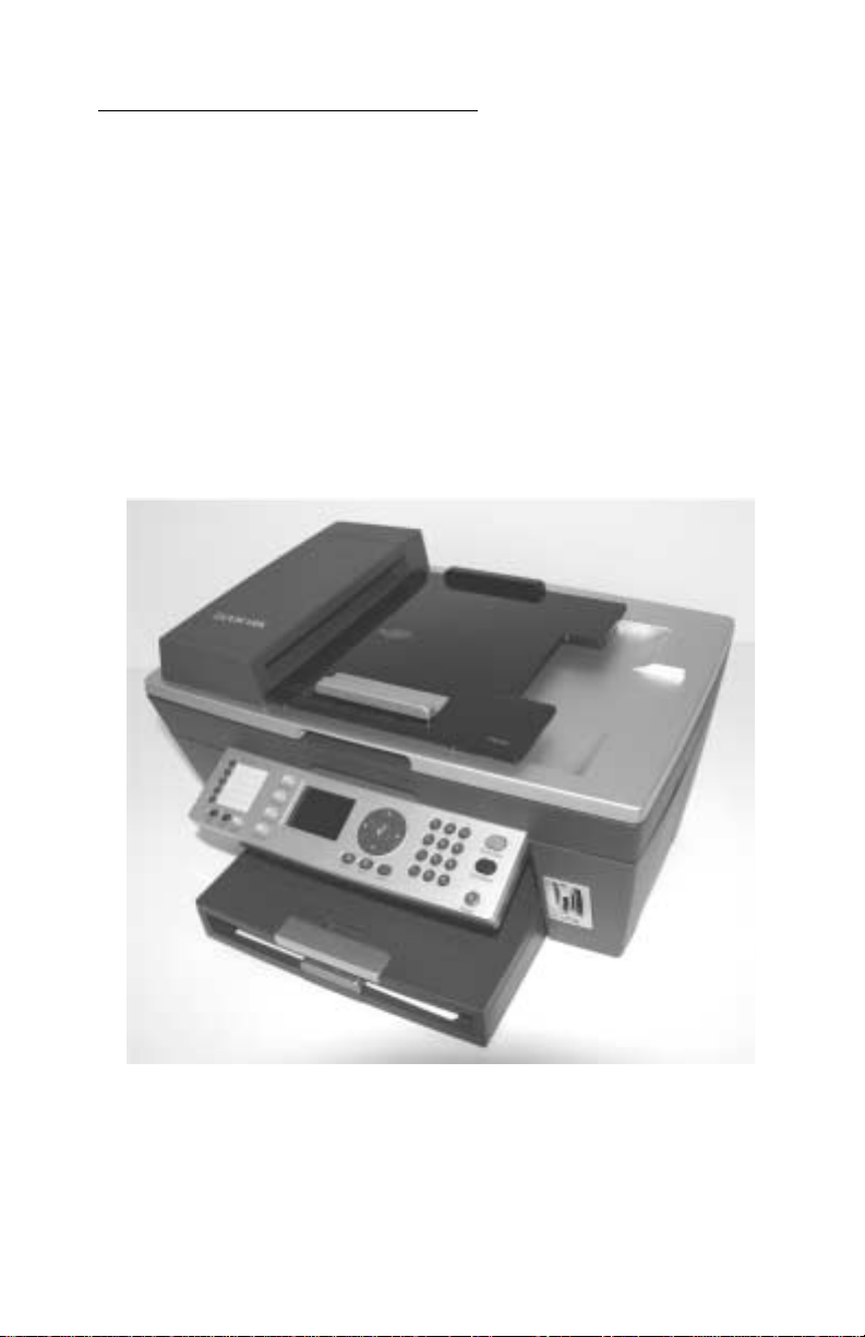
The Lexmark™ 8300 Series All-In-One (4419-X6X) is a letter-quality print,
fax, copy, and scan machine. It is a standalone color/mono copier and fax.
The printhead uses small heater plates and nozzles to control ink flow and
the formation of characters on the print media. The printhead assembly and
ink supply are combined into a single-unit print cartridge available as a
customer replaceable supply item. Dual printheads provide color and true
black printing without changing printheads. The number and size of inkjets
or nozzles in the printhead determines the overall quality and capability of
the printer. The black cartridge has a total of 640 nozzles and installs on the
left. The color cartridge has a total of 480 nozzles and installs on the right.
The photo cartridge has a total of 480 nozzles and installs on the left. The
All-In-One is capable of printing in two directions from either cartridge.
General information 1-1
Page 12

4419-X6X
Scanner specifications
Scanner Type Flatbed, Hybrid CIS/CCD
Scan Modes True Color:
• 48 bit internal
• 24 bit external
Gray Mode:
• 16 bit internal
• 8 bit external
Text/L in e Art:
1 bit per pixel
Scan Method One-pass scanning
Scan Area ADF Maximum:
• 8.5 x 14 inches
• 218 x 355 mm
Minimum:
• 8.27 x 11 inches
• 210 x 279.4 mm
Scan Resolution Flatbed Scanning:
• Horizontal: 1200 ppi (optical)
• Vertical: 2400 ppi
• Interpolated: 19,200 x 19,200
ADF:
• Horizontal: 600 ppi (optical)
• Vertical: 1200 ppi
• Interpolated: 9,600 x 9,600
1-2 Service Manual
Page 13

Copy specifications
Copy Modes From the control panel and host:
•Color
•Black
4419-X6X
Resolution/Quality Standalone Mode
The following options are available in
standalone mode. These apply to color
copy:
Photo–600 X 600 ppi Color Scan
1200 X 1200 dpi print (by interpolation for
all papers including glossy paper)
Normal–300 X 300 ppi Color Scan
600 X 600 dpi print (by interpolation for all
papers including glossy paper)
Quick–150 X 150 ppi Color Scan
• 300 X 600 dpi print (by interpolation)
• 600 X 600 dpi print (by interpolation for
glossy paper)
The following options are available in
standalone mode. These apply to blackand-white copy:
Photo–600 X 600 ppi Grayscale Scan
1200 X 1200 dpi print (by interpolation)
Normal–300 X 300 ppi Grayscale Scan
600 X 600 dpi print (by interpolation)
Quick–150 X 150 ppi Grayscale Scan
• 300 X 600 dpi print (by interpolation)
General information 1-3
Page 14

4419-X6X
Resolution/Quality Host-Based Mode
The following options are available in hostbased mode. These apply to color/
grayscale copy:
Photo–300 X 300 ppi Scan
• 1200 X 1200 dpi print
• 4800 X 1200 dpi print (for glossy paper)
Normal–200 X 200 ppi Scan
• 600 X 600 dpi print
• 1200 X 1200 dpi print (for glossy paper)
Quick–150 X 150 ppi Scan
• 300 X 600 dpi print
• 600 X 600 dpi print (for glossy paper)
The following options are available in hostbased mode. These apply to black-andwhite copy:
Photo–600 X 600 ppi Scan
• 1200 X 1200 dpi print
• 4800 X 1200 (for glossy paper)
Normal–300 X 300 ppi Scan
• 600 X 600 dpi print
• 1200 X 1200 dpi print (for glossy paper)
Quick–150 X 150 ppi Scan
• 300 X 600 dpi print
• 600 X 600 dpi (for glossy paper)
Print speed
Print Speeds • Quick print: 25 ppm mono/19 ppm color
• Normal print: 10 ppm mono/5 ppm color
1-4 Service Manual
Page 15
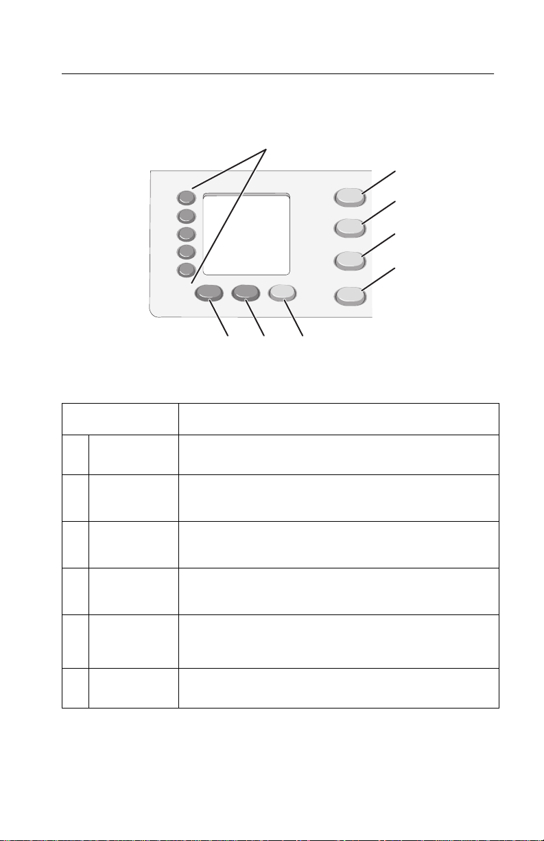
Using the control panel
7
8
Press To
4419-X6X
1
2
3
4
5
6
1 Quick Dial
buttons (1—5)
2 Copy Mode Access the copy menus and make copies.
3 Scan Mode Access the scan menus and scan documents.
4 Fax Mode Access the fax menus and send and receive faxes.
5 Photo Card Access the photo card menus. You can preview photos
6 Fax Auto
Answer
Access any of the five programmed Speed Dial
numbers.
Note: The mode is selected when the button light is on.
Note: The mode is selected when the button light is on.
Note: The mode is selected when the button light is on.
stored on a memory card or flash drive, edit the photos,
and print them.
Answer all incoming calls when lit.
General information 1-5
Page 16
4419-X6X
Press To
7 Redial/Pause • Redial the last number entered when the machine is
in Fax mode.
• Insert a three-second pause in the number to be
dialed. Enter a pause only when you have already
begun entering the number.
8 Phone Book Access any of the programmed Speed Dial numbers
(1—89) or Group Dial numbers (90—99).
1
2
3
4
5
678
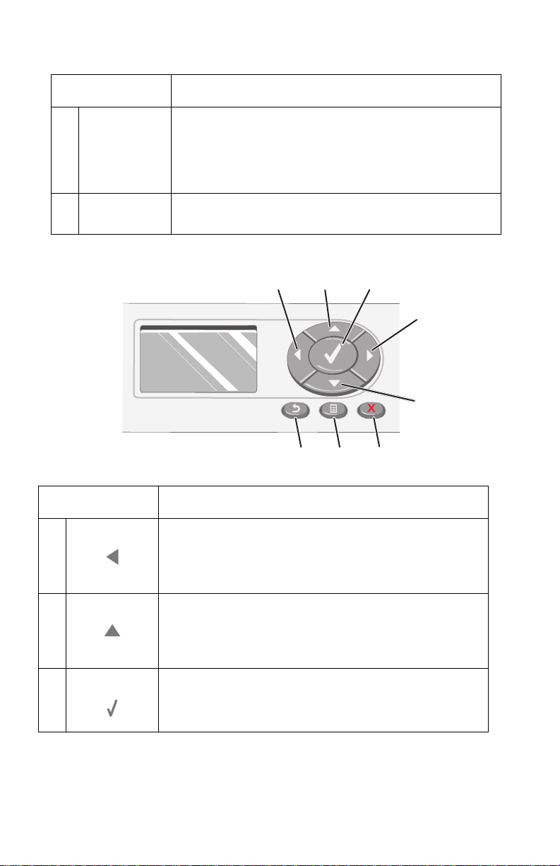
Press To
1 • Decrease a number.
• Scroll through options on the display.
• When cropping a photo, move the selected crop area
to the left.
2 • Increase a number.
• Scroll through menus or options on the display.
• When cropping a photo, move the selected crop area
up.
3 Choose the option that appears on the display, or save
settings. In Photo Card mode, select or deselect a
photo.
1-6 Service Manual
Page 17
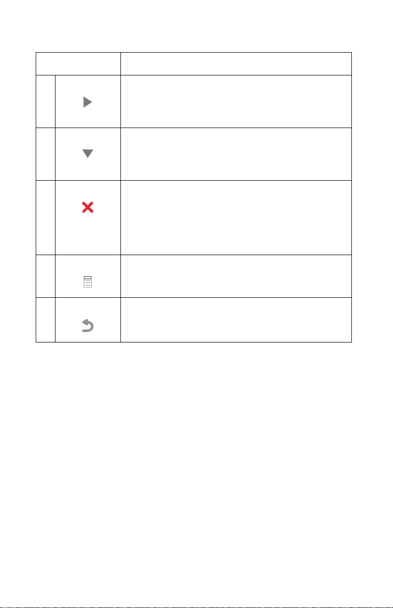
Press To
4 • Increase a number.
• Scroll through options on the display.
• When cropping a photo, move the selected crop area
to the right.
5 • De c re ase a number.
• Scroll through menus or options on the display.
• When cropping a photo, move the selected crop area
down.
6 • Cancel a scan, copy, or print job in progress.
• Clear a fax number or end a fax transmission, and
return the display to the fax default.
• Exit a menu.
• Clear current settings or error messages, and return
to default settings.
7 Display a control panel menu or submenu.
8 • Return to the previous submenu.
• Save the settings in a submenu, and return to the
previous menu.
4419-X6X
General information 1-7
Page 18
4419-X6X
1
4
7
*
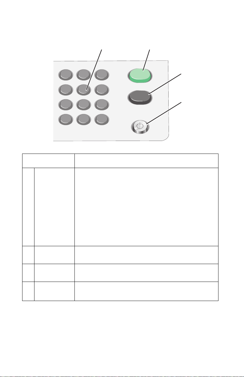
Press To
1 A keypad
number or
symbol
In Fax mode:
In Copy mode: Select the number of copies you want to
make.
In Photo Card mode: Select the number of photos you
want to print.
1
2
3
2
3
5 6
8 9
0
• Enter fax numbers.
• Navigate an automated answering system.
• Select letters when creating a Speed Dial list.
• Type numbers to enter or edit the date and time
#
shown on the display.
4
2 Start Color Start a color copy, scan, or photo job, depending on
3 Start Black Start a black-and-white copy, scan, fax, or photo job,
4 Power • Turn the All-In-One on and off.
which mode is selected.
depending on which mode is selected.
• Stop the print, copy, fax, or scan process.
1-8 Service Manual
Page 19

Maintenance approach
The diagnostic information in this manual leads you to the correct field
replaceable unit (FRU) or part. Use the error codes, symptom tables,
service checks, and diagnostic aids to determine the symptom and repair
the failure.
After you complete the repair, perform tests as needed to verify the repair.
Tools required for service
• Flat-blade screwdriver
• #1 Phillips screwdriver
• #2 Phillips screwdriver
• Spring hook
• Analog or digital multimeter
4419-X6X
General information 1-9
Page 20

4419-X6X
Acronyms
ADF Automatic Document Feeder
B/M Bill of Material
CCD Charge Coupled Device
CIS Contact Image Sensor
DBCS Double Byte Character Set
DPOF Digital Print Order Format
DPS Direct Print Service
EOF End of Form
ESD Electrostatic Discharge
FFC Flexible Flat Cable
FPC Flat Printhead Cable
FRU Field Replaceable Unit
HVPS High Voltage Power Supply
KB Kilobyte
KBps Kilobytes per second (usually as Kbps)/KiloBytes per second
LCD Liquid Crystal Display
LED Light-Emitting Diode
LVPS Low Voltage Power Supply
MPF Multipurpose Feeder
NVRAM Nonvolatile Random Access Memory
OEM Original Equipment Manufacturer
POR Power-On Reset
POST Power-On Self Test
ROM Read Only Memory
SBCS Single Byte Character Set
USB Universal Serial Bus
V ac Volts alternating current
V dc Volts direct current
ZIF Zero Insertion Force
(usually as KBps)
1-10 Service Manual
Page 21

4419-X6X
2. Diagnostic information
Use the error code tables, POST symptom table, symptom tables, and service
checks in this chapter to determine the All-In-One failure.
Start
Power-On Self Test (POST) sequence
Press the Power button to turn on the All-In-One.
1. The Power button light comes on.
2. The paper and transport carrier motors run, and then stop.
3. The CIS moves from the home position, and then returns.
4. The CIS lamp comes on, and then goes off.
5. The Fax Auto Answer, Copy Mode, Scan Mode, Fax Mode, Photo
Card, and Power button lights come on.
6. Lexmark X8300 All-In-One appears on the LCD.
7. The Fax Auto Answer, Copy Mode, and Power lights remain on.
8. Copy Mode appears on the LCD.
If the All-In-One completes POST with no errors, go to “Symptom tables”
on page 2-10, locate the symptom, and take the appropriate action.
If the All-In-One does not complete POST, go to the “POST symptom
table” on page 2-8, locate the symptom, and take the appropriate action.
Diagnostic information 2-1
Page 22

4419-X6X
Error codes
Code Name Description Action
0000 NVRAM R/W An error was detected
in reading or writing
NVRAM.
0001 Memory Failure Unable to initialize
memory
0002 Hardware
Failure
0200 Flash
Programming
1003 Paper System
Failure
General hardware
failure (unable to
localize failure to a
specific system)
Unable to program
Flash memory
Failure in initializing
DC paper feed system.
Replace the system
board.
Replace the system
board.
Replace the system
board.
Unplug the
All-In-One; wait a few
seconds, then plug
the All-In-One back
in, and turn the power
on. If the error
remains, replace the
USB cable. If the
error continues,
replace the system
board.
Unplug the All-InOne; wait a few
seconds, then plug
the All-In-One back
in, and turn the power
on. If the error
remains, replace the
system board.
11 00 Paper Jam There is paper jammed
in the All-In-One, or the
feed roller is stalled.
1 101 Paper Out The All-In-One is out of
paper.
1102 Incorrect
Printhead
1103 Missing
Printhead
Printhead ID is not
valid.
Printhead is missing. Install print cartridge.
2-2 Service Manual
Clear the paper jam,
and resend print job.
Load paper.
Replace the print
cartridge.
Page 23

Code Name Description Action
4419-X6X
1104 Printhead
Order
1105 Auto Alignment
Failed
1200 Print Carrier
Stall
1201 Print
Incomplete
1202 Data Error Incorrect data has
Unsupported order of
printheads
Automatic alignment
has failed.
The All-In-One print
carrier has stalled.
The print carrier
stopped before all the
data was used.
been sent from the
host computer to the
All-In-One.
Install the print
cartridges in the
correct slots.
Replace the print
cartridge.
Unplug the All-InOne; wait a few
seconds, then plug
the All-In-One back
in, and turn the power
on.
Resend the print job.
Unplug the All-InOne; wait a few
seconds, then plug
the All-In-One back
in, and turn the power
on. If the error
remains, replace the
USB cable. If the
error continues,
replace the system
board.
1203 Printhead Short A short test detected a
short-circuit in the
printhead.
1204 Printhead
Programming
1205 Mono TSR
Error
1206 Color TSR
Error
Unable to program
pseudo-random
printhead ID
Problem in mono TSR
circuit; cannot
determine printhead
temperature.
Problem in color TSR
circuit; cannot
determine printhead
temperature.
Diagnostic information 2-3
Replace the print
cartridge.
Replace the print
cartridge.
Replace the print
cartridge.
Replace the print
cartridge.
Page 24

4419-X6X
Code Name Description Action
1207 Paper System
Error
1208 Incorrect Home
Position
1209 Flash
Programming
Error
1210 Mode Select An invalid print mode
A paper system error
control failure was
detected.
The All-In-One is
unable to locate print
cartridge home
position.
Cannot program Flash
memory
was selected in print
command.
Clear the paper path.
Unplug the
All-In-One; wait a few
seconds, then plug
the All-In-One back
in, and turn the power
on. If the error
remains, replace the
system board.
Unplug the All-InOne; wait a few
seconds, then plug
the All-In-One back
in, and turn the power
on.
Unplug the
All-In-One; wait a few
seconds, then plug
the All-In-One back
in, and turn the power
on. If the error
remains, replace the
USB cable. If the
error continues,
replace the system
board.
Select a valid print
mode.
1211 USB Error An error was detected
in USB hardware, or
invalid results occurred
in USB code.
2-4 Service Manual
Unplug the
All-In-One; wait a few
seconds, then plug
the All-In-One back
in, and turn the power
on. If the error
remains, replace the
USB cable. If the
error continues,
replace the system
board.
Page 25

Code Name Description Action
4419-X6X
1212 Watchdog Error Indicates printer
system was reset by
Watchdog timer;
Subsystem stall failure.
1213 Data Abort
Error
1214 Invalid
Processor
Mode Error
1215 Math Error There is a problem
Firmware attempts to
load or store to an
invalid address.
Indicates the ARM
processor was in an
incorrect mode to
perform the requested
operation
doing math, such as
dividing by zero.
Unplug the
All-In-One; wait five
minutes, then plug
the All-In-One back
in, and turn the power
on. If the error
remains, replace the
system board.
Unplug the
All-In-One; wait a few
seconds, then plug
the All-In-One back
in, and turn the power
on. If the error
remains, replace the
system board.
Unplug the
All-In-One; wait a few
seconds, then plug
the All-In-One back
in, and turn the power
on. If the error
remains, replace the
system board.
Unplug the
All-In-One; wait a few
seconds, then plug
the All-In-One back
in, and turn the power
on. If the error
remains, replace the
system board.
1216 Mailbox Error There is a problem
with the internal
mailbox messaging
system.
1217 Temperature
Error
There is a problem
determining
temperature.
Unplug the
All-In-One; wait a few
seconds, then plug
the All-In-One back
in, and turn the power
on. If the error
remains, replace the
system board.
Replace the print
cartridge.
Diagnostic information 2-5
Page 26

4419-X6X
Code Name Description Action
1218 Serial Flash
Error
1219 Undefined
Signal Error
2100 Unlock
Scanner
2200 Scan Carrier
Stall
Invalid parameters
have been passed to
ReadFlashPage.
Microprocessor has
encountered a bad
signal (other than an
abort, illegal
instruction, or
arithmetic exception).
The scanner
mechanism is locked in
place or unable to
move due to other
failure.
The scan carrier has
stalled.
Unplug the
All-In-One; wait a few
seconds, then plug
the All-In-One back
in, and turn the power
on. If the error
remains, replace the
system board.
Unplug the
All-In-One; wait a few
seconds, then plug
the All-In-One back
in, and turn the power
on. If the error
remains, replace the
system board.
Unlock the scanner.
Unplug the All-InOne; wait a few
seconds, then plug
the All-In-One back
in, and turn the power
on. If the error
remains, check all
connections to the
scanner. If
connections are okay
and the error
continues, replace
the system board.
3100 Fax Error There is a general
error receiving or
sending fax.
4100 Invalid Media
Card
The inserted media
card is not valid for the
slot.
2-6 Service Manual
Try resending or
receiving fax.
Insert card in the
correct slot.
Page 27

Code Name Description Action
4419-X6X
4101 Media Card
R/W Error
120A Undefined Error Microprocessor has
120B Address Error Firmware attempted to
120C NVRAM Error An error was detected
There is a problem
reading or writing the
media card.
encountered an abort
or undefined
instruction.
access invalid address
space.
in reading or writing
NVRAM.
Replace the media
card.
Unplug the
All-In-One; wait a few
seconds, then plug
the All-In-One back
in, and turn the power
on. If the error
remains, replace the
system board.
Unplug the
All-In-One; wait a few
seconds, then plug
the All-In-One back
in, and turn the power
on. If the error
remains, replace the
system board.
Unplug the
All-In-One; wait a few
seconds, then plug
the All-In-One back
in, and turn the power
on. If the error
remains, replace the
system board.
120D Never Error Stack over and under
120E Software
Detected Error
flow error; Code error
An error condition was
detected in the
software control code.
Unplug the
All-In-One; wait a few
seconds, then plug
the All-In-One back
in, and turn the power
on. If the error
remains, replace the
system board.
Unplug the
All-In-One; wait a few
seconds, then plug
the All-In-One back
in, and turn the power
on. If the error
remains, replace the
system board.
Diagnostic information 2-7
Page 28

4419-X6X
Code Name Description Action
120F Printhead
Select
121A Loop Timeout
Error
121B NVRAM
Control Section
Corrupted
POST symptom table
Symptom Action
Installed printhead ID,
print command
printhead ID, or loaded
printhead records do
not agree.
Error detected that a
while loop or similar
loop timed out before
the event it was waiting
on finished.
Indicates that the
Control Section of
NVRAM is corrupted
Replace the print
cartridge.
Unplug the
All-In-One; wait a few
seconds, then plug
the All-In-One back
in, and turn the power
on. If the error
remains, replace the
system board.
Unplug the
All-In-One; wait a few
seconds, then plug
the All-In-One back
in, and turn the power
on. If the error
remains, replace the
system board.
Power, Copy, or
Scan lights do
not come on;
motors do not
operate.
The paper feed
gears do not
turn.
2-8 Service Manual
Go to the “Power service check” on page 2-19. If okay,
go to “Control panel problems” on page 2-10.
Go to the “Paper feed service check” on page 2-17.
Page 29

Symptom Action
4419-X6X
• The carrier
does not
move.
• The carrier
slams the
side frame.
• The CIS does
not move.
• The CIS lamp
does not
come on.
Go to the “Carrier transport service check” on
page 2-13.
Go to the “CIS module assembly service check” on
page 2-15.
Diagnostic information 2-9
Page 30

4419-X6X
Symptom tables
Locate the symptom in the following tables, and take the appropriate action.
Carrier transport problems
Symptom Action
• No carrier movement
• Slow carrier movement
• Carrier stops
• Carrier slams the side frame
Go to the “Carrier transport
service check” on page 2-13.
Maintenance station problems
Symptom Action
• Fails to cap the printheads
• Fails to clean the printheads
Go to the “Maintenance station
service check” on page 2-15.
Control panel problems
Symptom Action
• Butto ns do not work.
• LCD does not display.
If the LCD, buttons, or power light
fails, check the control panel cable
connection J6 on the system board,
and then run the “Power-On Self
Test (POST) sequence” on
page 2-1. If the problem remains,
replace the midframe cover with
control panel and risers. Go to
“Midframe cover with control
panel and risers removal” on
page 4-8.
If the problem continues, replace the
system board. Go to “System
board removal” on page 4-15.
2-10 Service Manual
Page 31

Printer communication problems
Symptom Action
4419-X6X
The computer does not
communicate with the printer.
Check the USB cable and system
board cable connections. If
connections are okay, replace the
system board. Go to the “System
board removal” on page 4-15.
Scanner problems
Symptom Action
• CIS does not move.
• Lamp does not come on.
• Scanned images are faded, or
colors are dull, blurry, or fuzzy.
Images are slanted or crooked
and the straight lines in the
image appear to be jagged or
uneven.
• Blank copies
PictBridge problems
Symptom Action
Go to the “CIS module assembly
service check” on page 2-15.
Go to the “Scan and copy quality
service check” on page 2-23.
The camera does not
communicate with the printer.
Check USB cable connections. If
connections are okay, go to the
“PictBridge service check” on
page 2-15.
Diagnostic information 2-11
Page 32

4419-X6X
Paper feed problems
Symptom Action
• Fails to pick up paper
• Picks up more than one sheet
of paper
• Picks paper but fails to feed
• Paper jams
• Paper fails to exit
• Noisy paper pick motor
• Noisy paper feed
• Envelopes fail to feed
• Paper skews
Go to the “Paper feed service
check” on page 2-17.
Power problems
Symptom Action
There is no power in the
All-In-One; motors do not operate.
Go to the “Power service check”
on page 2-19.
Print quality problems
Symptom Action
• Voids in characters
• Light print
• Prints off the page
• Fuzzy print
• Carrier moves but nothing
prints
• Printhead dries prematurely
• Colors print incorrectly
• Vertical alignment off
Go to the “Print quality service
check” on page 2-20.
2-12 Service Manual
Page 33

Service checks
Carrier transport service check
Unit/Problem Action
4419-X6X
Carrier Transport
Motor
Carrier Guide Rod Clean and lubricate the carrier rod.
Encoder Strip Verify that the encoder strip is installed correctly and is
Check the carrier transport motor connector J10 on the
system board. If it is connected, check for
approximately 30 V dc on pins 1 and 2 or at the wire
connections located on the rear of the carrier transport
motor. If voltage is incorrect, replace the system board.
Go to “System board removal” on page 4-15. If
voltage is correct, check the motor for binds or a loose
motor pulley.
A noisy or chattering motor or a motor that fails to turn
can be caused by:
• A broken circuit or short-circuit in the motor
• A bind in the carrier transport mechanism
Disconnect the carrier transport motor cable J10 from
the system board, and check for 15 ohms between the
two wires on the carrier transport motor. If the reading
is incorrect, replace the print engine. Go to “Print
engine removal” on page 4-17.
Lubricate the carrier rod and the carrier rod bearing
surfaces with grease P/N 40X0179.
free of grease or dirt. If the encoder strip is not installed
correctly, it can cause the carrier to slam against the
side frame. If the encoder strip is damaged, replace it.
Go to “Encoder strip removal” on page 4-16.
If the encoder strip and all connections are okay, but
the carrier slams the side frame, replace the system
board. Go to “System board removal” on page 4-15.
Diagnostic information 2-13
Page 34

4419-X6X
Unit/Problem Action
Carrier Assembly Check the following parts for wear or damage:
• Printhead cartridge latch
• Latch spring
• Carrier
• Printhead cables
Ensure that all printhead cables are fully seated.
If any of these parts are defective, replace the carrier
assembly . Go to “Carrier assembly with cables, belt,
and cable clip removal” on page 4-18.
Check the gold-plated contacts located on the inside
(rear) of the printhead carrier for dirt, wear, and
damage. Use a clean cloth dampened with water to
clean the contacts. Let the contacts dry completely. If
the gold contacts are damaged, replace the carrier
assembly . Go to “Carrier assembly with cables, belt,
and cable clip removal” on page 4-18.
If the symptom remains, replace the system board. Go
to “System board removal” on page 4-15.
2-14 Service Manual
Page 35

CIS module assembly service check
Unit/Problem Action
4419-X6X
CIS Module
Assembly
If the CIS module does not move, ensu re th at th e be lt
is installed and is not binding. Check the scanner
motor connector JP3 on the system board for proper
connection. If the CIS module still does not move,
replace the system board. Go to “System board
removal” on page 4-15.
If the lamp does not come on as the CIS module
assembly is scanning, check connector J12 on the
system board. If the connection is okay and the
problem remains, replace the scanner module
assembly. Go to “Scanner module assembly
removal” on page 4-6.
PictBridge service check
Unit/Problem Action
PictBridge
Card
Check system board connector P1 for approximately
4.9 V dc on pin 1. If the voltage is incorrect, replace the
system board. Go to “System board removal” on
page 4-15. If the voltage is correct but the problem
remains, replace the card reader card with PictBridge
assembly and cables. Go to “Card reader card with
PictBridge assembly and cables removal” on
page 4-13.
Maintenance station service check
The maintenance station has three functions:
1. Wipes (cleans) the printhead nozzle plates
2. Provides a place for printheads to fire all nozzles, keeping them clean
for printing
Diagnostic information 2-15
Page 36

4419-X6X
3. Seals the printheads when they are not being used to prevent the
nozzles from drying
Unit/Problem Action
Maintenance
Station
Assembly
As the carrier moves to the left over the maintenance
station, a slot on the bottom of the carrier engages a tab
on the sled of the maintenance station, causing the cap
to rise and seal the printheads. When the carrier moves
to the right, it uncaps the printheads. The wipers clean
the printhead nozzle plates as the carrier leaves the
maintenance station. The wipers clean the printheads
only when the carrier is moving to the right. After the
cleaning operation is complete, a tab on the
maintenance station engages a tab on the carrier,
causing the wipers to lower.
Worn wipers can cause poor print quality after printhead
cleaning. Check for loose or worn wipers.
Worn caps cause the printhead nozzles to dry and clog.
Check for loose or worn caps.
If any worn or broken parts are found, replace the
maintenance station. Go to “Maintenance station
removal” on page 4-19.
2-16 Service Manual
Page 37

4419-X6X
Paper feed service check
If the All-In-One does not have paper jam problems, continue with this
service check. If the All-In-One has paper jam problems, examine the printer
for the following before you begin the service check:
• Check the entire paper path for obstructions.
• Ensure there is not too much paper in the paper tray.
• Ensure the correct type of paper is being used.
• Check for static in the paper.
Unit/Problem Action
• Paper Feed
Motor
• System Board
Run the “Power-On Self Test (POST) sequence” on
page 2-1.
A noisy or chattering motor or a motor that fails to turn
can be caused by:
• A broken circuit or short-circuit in the motor
• A bind in the paper feed mechanism
Disconnect paper feed motor cable J11 from the
system board, and check for approximately 25 ohms
between the two wires on the paper feed motor. If the
reading is incorrect, replace the print engine. Go to
“Print engine removal” on page 4-17. If the reading
is correct, check for approximately 30 V dc at
connector J11 on pins 1 and 2. If the voltage is
incorrect, replace the system board. Go to “System
board removal” on page 4-15.
Although the paper feeds in one direction, the paper
feed motor turns in two directions. If the paper feed
motor turns in one direction only, replace the system
board. Go to “System board removal” on page 4-15.
Binds in the paper feed motor or gear train can cause
intermittent false paper jam errors. Remove the paper
feed motor, and check the shaft for binds. Also check
for a loose or worn motor gear. If the gear is defective,
replace the print engine. Go to “Print engine
removal” on page 4-17.
Diagnostic information 2-17
Page 38

4419-X6X
Unit/Problem Action
Paper Pick
Assembly
ADF Scanner Lid
Assembly
Midframe
Assembly
Check the paper pick motor connector J17 on the
system board. If it is connected, check for
approximately 30 V dc on pins 1 and 2 or at the wire
connections located on the rear of the paper pick
motor. If voltage is incorrect, replace the system board.
Go to “System board removal” on page 4-15. If the
voltage is correct, replace the printer base assembly
with cover and paper pick assembly. Go to “Printer
base with cover and paper pick assembly removal”
on page 4-22.
Check the pick roller for wear. If the pick roller is worn
and causing a paper feed problem, replace the printer
base assembly with cover and paper pick assembly.
Go to “Printer base with cover and paper pick
assembly removal” on page 4-22.
Check the ADF paper feed motor connector J4 on the
system board for proper connection.
Check the ADF paper feed sensor connector J15 on
the system board. If it is connected, check for
approximately 1.2 V dc on pin 1 and 3.2 V dc on pin 3.
If the voltage is incorrect, replace the ADF scanner lid
assembly. Go to “ADF scanner lid assembly
removal” on page 4-5.
Check the following for wear:
• Small feed rollers
• Large feed roller
• Exit roller
• Star rollers
End-of-Forms
Flag
ADF
End-of-Forms
Flag
2-18 Service Manual
If any of the rollers are worn and causing a paper feed
problem, replace the print engine. Go to “Print engine
removal” on page 4-17.
Check for binds or damage. If the flag is defective,
replace the print engine. Go to “Print engine
removal” on page 4-17.
Check for binds or damage. If the flag is defective,
replace the ADF scanner lid assembly. Go to “ADF
scanner lid assembly removal” on page 4-5.
Page 39

Power service check
Unit/Problem Action
4419-X6X
External Power
Supply
• Printhead
Cables
• Paper Feed
Motor
• Carrier
Transport
Motor
• Control Panel
Plug the external power supply into an outlet, and
check for 30 V dc. If the voltage is incorrect, replace
the power supply.
Unplug the All-In-One. Check all connections on the
system board, and plug the All-In-One back in. Look for
a symptom change.
If the printhead cables are defective, replace the carrier
assembly . Go to “Carrier assembly with cables, belt,
and cable clip removal” on page 4-18.
Check for broken circuits or short-circuits in the paper
feed and carrier transport motors. If either motor is
defective, replace the print engine. Go to “Print
engine removal” on page 4-17.
If the control panel LCD, buttons, or power light fails,
check cable connection J6 on the system board, and
then run the “Power-On Self Test (POST) sequence”
on page 2-1. If the problem remains, replace the
midframe cover with control panel and risers. Go to
“Midframe cover with control panel and risers
removal” on page 4-8.
If the problem continues, replace the system board. Go
to “System board removal” on page 4-15.
Diagnostic information 2-19
Page 40

4419-X6X
Print quality service check
Unit/Problem Action
Alignment Uneven vertical lines and characters not properly
formed (jagged or rough) or not aligned at the left
margin can be adjusted by performing the print
cartridge alignment.
Aligning print cartridges using the control panel
1. Load plain paper.
2. From the control panel, press Copy Mode.
3. Press .
4. Press or repeatedly until Maintenance is
highlighted.
5. Press .
6. Press or repeatedly until Align
Cartridges is highlighted.
7. Press .
An alignment page prints.
If you aligned the cartridges to improve print quality,
print your document again. If print quality has not
improved, clean the print cartridge nozzles.
Aligning print cartridges using the Productivity
Suite
1. Load plain paper.
2. From the desktop, double-click the Productivity
Suite icon, and then click Maintain/Troubleshoot.
3. Click the Maintenance tab.
4. Click Align to fix blurry edges.
5. Click Print.
An alignment page prints.
If you aligned the cartridges to improve print quality,
print your document again. If print quality has not
improved, clean the print cartridge nozzles.
2-20 Service Manual
Page 41

Unit/Problem Action
Print Cartridge Ensure that the All-In-One contains good print
cartridges.
Clean the print cartridge nozzles when:
• Characters are not printing completely.
• White dashes appear in graphics or printed text.
• Print is smudged or too dark.
• Vertical, straight lines are not smooth.
• Colors on print jobs are faded, or they dif fer from the
colors on the screen.
Cleaning the print cartridge nozzles using the
control panel
1. Load plain paper.
2. Press Copy Mode.
3. Press .
4. Press .
5. Press .
6. Press until Clean Cartridges is highlighted.
7. Press .
8. A page prints, forcing ink through the print cartridge
nozzles to clean them.
9. Print the document again to verify that the print
quality has improved.
If print quality has not improved, try cleaning the
nozzles up to two more times.
Cleaning the print cartridge nozzles using the
Productivity Suite
1. Load plain paper.
2. From the desktop, double-click the Productivity
Suite icon, and then click Maintain/Troubleshoot.
3. Click the Maintenance tab.
4. Click Clean to fix horizontal streaks.
5. Click Print.
A page prints, forcing ink through the print cartridge
nozzles to clean them.
6. Print the document again to verify that the print
quality has improved.
7. If print quality has not improved, try cleaning the
nozzles up to two more times.
4419-X6X
Diagnostic information 2-21
Page 42

4419-X6X
Unit/Problem Action
Color print
cartridge cross
contamination
Maintenance
Station
Paper Feed Ink smudging and smearing can be caused by paper
Be sure the print cartridge nozzle plate is clean. Clean
with a clean, lint-free cloth dampened with water.
If cross contamination occurs, check for:
• Maintenance station wiper damage
• Used tape on the printhead nozzle plate
If the wiper is damaged, replace the maintenance
station. Go to “Maintenance station removal” on
page 4-19.
Note: Do not retape the printhead nozzle plate.
Intermittent nozzle failures can be caused by worn
parts in the maintenance station. If you find worn parts,
replace the maintenance station. Go to “Maintenance
station removal” on page 4-19.
problems or problems in the paper feed area. Check
for:
• Correct type of paper
• Curled or wrinkled paper
• Paper path obstructions
• Feed roller wear or looseness
• Worn gears or binds
If the paper feed roller or gears are defective, replace
the print engine. Go to “Print engine removal” on
page 4-17.
Carrier Transport Blurred print and voids can be caused by problems in
the carrier transport area. Check the following:
• Carrier transport belt for wear
• Idler pulley parts for wear, damage, or looseness
• Carrier guide rod for wear or dirt. If the rod is dirty,
clean and lubricate it.
The carrier to carrier frame engagement should be
lubricated with grease P/N 40X0179.
If the carrier transport belt is worn, replace the carrier
assembly . Go to “Carrier assembly with cables, belt,
and cable clip removal” on page 4-18.
If the idler pulley parts are defective, replace the print
engine. Go to “Print engine removal” on page 4-17.
2-22 Service Manual
Page 43

Scan and copy quality service check
Unit/Problem Action
4419-X6X
Scanned images
have:
• Blank pages
• Checkerboard
pattern
•Distorted
graphics or
pictures
• Missing
characters
• Faded print
• Dark print
• Skewed lines
• Smudges
• Streaks
• Unexpected
characters
• White lines in
print
If the scanner glass is dirty, gently wipe it with a clean,
lint-free cloth dampened with water.
Make sure all ink or corrective fluid is dry before
placing a document on the scanner glass.
Make sure the document or photo is loaded correctly in
the ADF or on the scanner glass.
Check the ink levels, and install a new print cartridge if
necessary.
To adjust the Brightness setting:
1. Load the document face down on the scanner glass.
2. From the control panel, press Copy Mode.
3. Press or repeatedly until Lighter /
Darker is highlighted.
4. Press or to lighten or darken the copy.
5. Press .
Diagnostic information 2-23
Page 44

4419-X6X
2-24 Service Manual
Page 45

4419-X6X
3. Diagnostic aids
Test page
This test prints the test page.
To run a complete test page of black and color patterns, be sure the
printhead cartridges are in good condition.
To enter the test:
1. Turn on the All-In-One.
2. Lift the scanner unit.
3. Install a good black print cartridge in the left side of the carrier and a
good color cartridge in the right.
4. Close the scanner unit.
5. Load paper in the paper support.
6. Press until Maintenance appears on the LCD.
7. Highlight Maintenance and press .
8. Print Test Page appears on the LCD.
9. Highlight Print Test Page and press to print the test page.
The test page consists of the following information:
• Build Date
• Code Level
• Page Count
• ASIC Version
• Temps
• USB Product
• USB Manufacturer
• USB Serial Number
• MFG
• CMD
• Model
• Class
• DES
• USB Vendor ID
There is a black and color purge pattern used to clear all printhead nozzles.
The nozzle test pattern prints all nozzles on a diagonal line. There should be
no breaks in the nozzle test pattern. A break in the pattern indicates one or
more nozzles are not working.
Diagnostic aids 3-1
Page 46

4419-X6X
If a print quality problem exists, see “Print quality service check” on
page 2-20.
3-2 Service Manual
Page 47

4419-X6X
4. Repair information
This chapter explains how to make adjustments to the All-In-One and how to
remove defective parts.
Warning: Read the following before handling electronic parts.
Handling ESD-sensitive parts
Many electronic products use parts that are known to be sensitive to
electrostatic discharge (ESD). To prevent damage to ESD-sensitive parts,
follow the instructions below:
• Keep the ESD-sensitive part in its original shipping container (a special
“ESD bag”) until you are ready to install the part into the machine.
• Make as few movements as possible with your body to prevent an
increase of static electricity from clothing fibers, carpets, and furniture.
• Put the ESD wrist strap on your wrist. Connect the wrist band to the
system ground point. This discharges any static electricity in your body
to the machine.
• Hold the ESD-sensitive part by its edge connector shroud (cover); do
not touch its pins. If you are removing a pluggable module, use the
correct tool.
• Do not place the ESD-sensitive part on the machine cover or on a
metal table; if you need to put down the ESD-sensitive part for any
reason, first put it into its special bag.
• Machine covers and metal tables are electrical grounds. They increase
the risk of damage because they make a discharge path from your
body through the ESD-sensitive part. (Large metal objects can be
discharge paths without being grounded.)
• Prevent ESD-sensitive parts from being accidentally touched by other
personnel. Install machine covers when you are not working on the
machine, and do not put unprotected ESD-sensitive parts on a table.
• If possible, keep all ESD-sensitive parts in a grounded metal cabinet
(case).
• Be extra careful in working with ESD-sensitive parts when cold-
weather heating is used, because low humidity increases static
electricity.
Repair information 4-1
Page 48

4419-X6X
Adjustments
The user is directed in the Lexmark Solution Center to perform the printhead
alignment adjustments after replacing a print cartridge.
Removal procedures
The following procedures are arranged according to the name of the
All-In-One part discussed.
CAUTION: Unplug the power cord before removing any parts.
Releasing plastic latches
Many of the parts are held in place with plastic latches. The latches break
easily; release them carefully. To remove such parts, press the hook end of
the latch away from the part to which it is latched.
4-2 Service Manual
Page 49

4419-X6X
Removals
General precautions on removals
Use caution when disassembling and reassembling components. The close
proximity of cables to moving parts makes proper routing a must. When
components are removed or replaced, any cables disturbed must be
replaced as closely as possible to their original positions. Before removing
any component from the machine, be sure you note the cable routing.
When servicing the machine:
• Verify that documents are not stored in memory.
• Move the print cartridge to the far right to cap the nozzles.
• Unplug the power cord.
• Use a flat and clean surface.
• Use only authorized replacement parts.
• Do not force plastic parts.
Control panel cover removal
1. Lift the scanner module assembly until the risers extend.
2. Separate the cover from the base of the control panel, and lift to
remove.
Repair information 4-3
Page 50

4419-X6X
Rear access cover removal
1. Remove screw (A).
2. Remove the rear access cover.
4-4 Service Manual
Page 51

ADF scanner lid assembly removal
1. Remove the rear access cover.
2. Remove ground cable screw (A), and disconnect three cables (B) from
the system board.
4419-X6X
3. Raise the ADF scanner lid assembly to the upright position.
4. Separate the ADF scanner lid hinges (C) from the scanner module
assembly.
Repair information 4-5
Page 52

4419-X6X
5. Lift to remove.
Scanner module assembly removal
1. Remove the rear access cover.
2. Disconnect J12 (A) and JP3 (B) from the system board.
3. Lift the scanner module assembly until the risers extend.
4-6 Service Manual
Page 53

4. Disconnect both risers.
5. Lift the scanner module assembly, and remove.
4419-X6X
Repair information 4-7
Page 54

4419-X6X
Midframe cover with control panel and risers removal
1. Remove the rear access cover.
2. Remove the ADF scanner lid assembly.
3. Remove the scanner module assembly.
4. Remove the control panel cover.
5. Remove ten screws (A).
4-8 Service Manual
Page 55

4419-X6X
6. Lift the midframe cover to disconnect J6 (B) from the system board.
7. Remove the midframe cover with control panel and risers.
Repair information 4-9
Page 56

4419-X6X
Rear access door with sensor removal
1. Remove the rear access cover.
2. Disconnect JP2 (A) from the system board.
4-10 Service Manual
Page 57

4419-X6X
3. Use a flat thin-blade screwdriver to separate the rear access door
hinge from the base cover.
4. Remove the rear access door with sensor.
Repair information 4-11
Page 58

4419-X6X
Fax card removal
1. Remove the rear access cover.
2. Remove the ADF scanner lid assembly.
3. Remove the scanner module assembly.
4. Disconnect J7 (A) from the fax card.
5. Remove three screws (B).
6. Lift and remove the fax card.
4-12 Service Manual
Page 59

4419-X6X
Card reader card with PictBridge assembly and cables removal
1. Remove the rear access cover.
2. Remove the ADF scanner lid assembly.
3. Remove the scanner module assembly.
4. Remove the midframe cover with control panel and risers.
5. Remove the fax card.
6. Disconnect P3 (A) and P1 (B) from the system board.
Repair information 4-13
Page 60

4419-X6X
7. Remove two screws (C).
8. Remove the card reader card with PictBridge assembly and cables.
4-14 Service Manual
Page 61

System board removal
1. Remove the rear access cover.
2. Remove the ADF scanner lid assembly.
3. Remove the scanner module assembly.
4. Remove the midframe cover with control panel and risers.
5. Disconnect all cables from the system board.
6. Remove six screws (A).
4419-X6X
7. Lift and remove the system board.
Repair information 4-15
Page 62

4419-X6X
Encoder strip removal
1. Remove the rear access cover.
2. Remove the ADF scanner lid assembly.
3. Remove the scanner module assembly.
4. Remove the midframe cover with control panel and risers.
5. Disconnect both ends of the encoder strip (A).
6. Remove the encoder strip.
4-16 Service Manual
Page 63

Print engine removal
1. Remove the rear access cover.
2. Remove the ADF scanner lid assembly.
3. Remove the scanner module assembly.
4. Remove the midframe cover with control panel and risers.
5. Remove the rear access door with sensor.
6. Remove the fax card.
7. Disconnect power supply and existing cable from the system board.
8. Remove seven screws (A).
4419-X6X
9. Lift, tilt, and remove the print engine.
Repair information 4-17
Page 64

4419-X6X
Carrier assembly with cables, belt, and cable clip removal
1. Remove the rear access cover.
2. Remove the ADF scanner lid assembly.
3. Remove the scanner module assembly.
4. Remove the midframe cover with control panel and risers.
5. Remove the print engine assembly.
6. Remove the encoder strip.
7. Remove the carrier shaft retainer clips (A).
8. Remove the carrier shaft through the left side.
9. Press the carrier belt tensioner (B), and remove the belt (C).
10. Unplug the carrier cables from the system board.
4-18 Service Manual
Page 65

4419-X6X
11. Press cable latch (D), pull the cables through the slot, and remove the
carrier assembly.
Maintenance station removal
1. Remove the rear access cover.
2. Remove the ADF scanner lid assembly.
3. Remove the scanner module assembly.
4. Remove the midframe cover with control panel and risers.
5. Remove the print engine assembly.
Repair information 4-19
Page 66

4419-X6X
6. Press two latches (A).
7. Slide the maintenance station forward and remove.
4-20 Service Manual
Page 67

Exit tray removal
1. Remove the rear access cover.
2. Remove the ADF scanner lid assembly.
3. Remove the scanner module assembly.
4. Remove the midframe cover with control panel and risers.
5. Remove the print engine assembly.
6. Use a flat thin-blade screwdriver to separate the exit tray hinge from
the base cover.
4419-X6X
7. Lift and remove the exit tray.
Repair information 4-21
Page 68

4419-X6X
Printer base with cover and paper pick assembly removal
1. Remove the rear access cover.
2. Remove the ADF scanner lid assembly.
3. Remove the scanner module assembly.
4. Remove the midframe cover with control panel and risers.
5. Remove the print engine assembly.
6. Remove the exit tray.
The printer base with cover and paper pick assembly remains.
• kkkkkkkkkkkkkkkkkkkkkkkkkkkkkkkkkkkkkkkkkkkkkkkkkkkkkkkkkkkkkkkk
kkkkkkkkkkkkkkkkkkkkk
4-22 Service Manual
Page 69

5. Locations and connectors
System board
Connector Description Approximate voltage
J1 Power Supply Pin 1–30 V dc 2
4419-X6X
Connector
(total number
of pins)
J4 ADF Paper
Feed Motor
J5 Fax Card
J6 Control Panel Ribbon
J7 Carrier Ribbon
J8 Carrier Ribbon
J9 Carrier Ribbon
J10 Carrier
Transport
Motor
J11 Paper Feed
Motor
J12 CIS Scanner
Lamp
J15 ADF Paper
Feed Sensor
J16 ADF End of
Forms Sensor
J17 Paper Pick
Motor
Pins 1 and 2–30 V dc 2
Pins 1 and 2–30 V dc 2
Pin 1–1.2 V dc
Pin 3–3.2 V dc
Pin 1–1.2 V dc
Pin 3–3.2 V dc
Pins 1 and 2–30 V dc 2
4
Ribbon
4
4
J18 Paper Pick
Sensor
P1 PictBridge Pin 1–4.9 V dc 5
P2 USB
Locations and connectors 5-1
4
Page 70

4419-X6X
Connector Description Approximate voltage
P3 Card Reader Pin 3–2.9 V dc 5
Connector
(total number
of pins)
JP1 Paper Encoder
Dial Sensor
JP2 Rear Door
Media Sensor
JP3 Scanner Motor 4
U6 Cartridge
Access Sensor
Pin 1–4.8 V dc
Pin 2–4.8 V dc
Pin 3–4.8 V dc
Pin 4–4.8 V dc
Ribbon
4
5-2 Service Manual
Page 71

4419-X6X
Locations and connectors 5-3
Page 72

4419-X6X
Fax card
Connector Description Approximate voltage
J7 Speaker 2
Connector
(total number
of pins)
5-4 Service Manual
Page 73

PictBridge and card reader
Connector Description Approximate voltage
J1 PictBridge Pin 1–4.9 V dc 5
J1 Card Reader Pin 3–2.9 V dc 5
4419-X6X
Connector
(total number
of pins)
Locations and connectors 5-5
Page 74

4419-X6X
5-6 Service Manual
Page 75

4419-X6X
6. Preventive maintenance
This chapter contains lubrication specifications. Follow these
recommendations to prevent problems and maintain optimum performance.
Lubrication specifications
Lubricate only when parts are replaced or as needed, not on a scheduled
basis. Use grease P/N 40X0179 to lubricate the following:
• All gear mounting studs
• The left and right ends of the large feed roller at the side frames
• The carrier to carrier frame engagement
• The carrier guide rod, and carrier guide rod bearings
Warning: Keep grease from coming into contact with any electrical
components, as this may cause All-In-One damage or failure. Do not
lubricate the scanner rod or bearing after replacing.
Preventive maintenance 6-1
Page 76

4419-X6X
6-2 Service Manual
Page 77

7. Parts catalog
How to use this parts catalog
The following legend is used in the parts catalog:
4419-X6X
AsmIndex
Part
number
Units/
mach
Units/
FRU
Description
• Asm-index: Identifies the assembly and the item in the diagram. For
example, 2-1 indicates assembly 2 and item number 1.
• Part number: Identifies the unique number that identifies this FRU.
• Units/mach: Refers to the number of units actually used in the
machine or product.
• Units/FRU: Refers to the number of units packaged together and
identified by the part number.
• NS: (Not shown) in the Asm-Index column indicates that the part is
procurable but is not pictured in the illustration.
• PP: (Parts Packet) in the parts description column indicates that the
part is contained in a parts packet.
Parts catalog 7-1
Page 78

4419-X6X
Assembly 1: Covers
7-2 Service Manual
Page 79

Assembly 1: Covers
4419-X6X
AsmIndex
1—1 40X2468 1 1 Cover, midframe with control panel
NS 7375511 1 1 Plain package B/M includes: carton,
Part
number
2 21M0835 1 1 Cover, control panel English
2 21M0837 1 1 Cover, control panel Dutch
2 21M0839 1 1 Cover, control panel French
2 21M0841 1 1 Cover, control panel German
2 21M0843 1 1 Cover, control panel Greek
2 21M0845 1 1 Cover, control panel Hebrew
2 21M0847 1 1 Cover, control panel Italian
2 21M0849 1 1 Cover, control panel Japanese
2 21M0851 1 1 Cover, control panel Korean
2 21M0853 1 1 Cover, control panel Polish
2 21M0855 1 1 Cover, control panel Brazilian
2 21M0857 1 1 Cover, control panel Russian
2 21M0859 1 1 Cover, control panel Simplified
2 21M0861 1 1 Cover, control panel Spanish
2 21M0863 1 1 Cover, control panel Traditional
2 21M0865 1 1 Cover, control panel Turkish
3 40X2471 1 1 Door, rear access with sensor
4 40X2470 1 1 Cover, rear access
5 40X2469 1 1 Base, printer with cover
6 40X2473 1 1 Tray, exit
Units/
mach
Units/
FRU
Description
and risers
Portuguese
Chinese
Chinese
cushion set, and sealing tape
Parts catalog 7-3
Page 80

4419-X6X
Assembly 1 (cont.): Covers
7-4 Service Manual
Page 81

Assembly 1 (cont.): Covers
4419-X6X
AsmIndex
1—1 40X2462 1 1 Lid, ADF scanner assembly
Part
number
2 40X2463 1 1 Module, scanner assembly
Units/
mach
Units/
FRU
Description
Parts catalog 7-5
Page 82

4419-X6X
Assembly 2: Engine, electronics, and carrier
7-6 Service Manual
Page 83

Assembly 2: Engine, electronics, and carrier
4419-X6X
AsmIndex
2—1 40X2466 1 1 Card, fax
NS 11B6502 1 1 Cord, power Australia
NS 11B6503 1 1 Cord, power UK, Hong Kong
NS 11B6504 1 1 Cord, power Europe, Asia
NS 11B6507 1 1 Cord, power South Africa
NS 11B6508 1 1 Cord, power Chile
NS 11B6510 1 1 Cord, power Brazil
NS 11B6511 1 1 Cord, power Japan
NS 11B6512 1 1 Cord, power Argentina
NS 11B6513 1 1 Cord, power Peoples Republic of
NS 11B6514 1 1 Cord, power Korea
NS 11B6515 1 1 Cord, power Taiwan
NS 11B6516 1 1 Cord, power India
NS 11B6532 1 1 Cord, power Japan - 2.5 Amp 6 foot
Part
number
2 40X2465 1 1 Board, system
3 40X2461 1 1 Strip, encoder
4 40X2464 1 1 Engine, print
5 40X2467 1 1 Card, reader card and Pictbridge
6 40X2472 1 1 Carrier, assembly with cables, belt,
7 40X2460 1 1 Station, maintenance
8 21H0302 1 1 Supply, power universal 32 W
9 11B6501 1 1 Cord, power USA, Peru, Canada,
Units/
mach
Units/
FRU
Description
assembly
and cable clip
LAD
China
3 conductor
Parts catalog 7-7
Page 84

4419-X6X
7-8 Service Manual
Page 85

Index
A
acronyms 1-10
adjustments
B
buttons
Cancel
Copy Mode
Down Arrow
Fax Auto Answer
Fax Mode
Keypad
Left Arrow
Menu
Phone Book
Photo Card
Power
Quick Dial
Redial/Pause
Return
Right Arrow
Scan Mode
Select (check)
Start Black
Start Color 1-8
Up Arrow
C
carrier transport problems 1-10
CIS module assembly
control panel 1-5
control panel problems
copy specifications
D
diagnostic aids
test page 1-1
diagnostic information
error codes
POST (Power-On Self Test)
sequence
POST symptom table
1-2
1-7
1-5
1-7
1-5
1-5
1-8
1-6
1-7
1-6
1-5
1-8
1-5
1-6
1-7
1-7
1-5
1-6
1-8
1-6
1-15
1-10
1-3
1-1
1-2
1-1
1-8
4419-X6X
1-1
start
symptom tables
1-10
E
error codes 1-2
ESD-sensitive parts
1-1
G
general information 1-1
H
handling ESD-sensitive parts 1-1
L
LCD 1-1, 1-10
locations and connectors
fax card
PictBridge and card reader
system board
lubrication specifications
1-4
1-1
1-1
1-5
1-1
M
maintenance approach 1-9
maintenance station 1-15
maintenance station problems
1-10
P
paper feed 1-17
paper feed problems
paper jam 1-12
parts catalog
carrier
covers 1-2, 1-4
electronics
how to use
print engine 1-6
PictBridge 1-15
PictBridge problems
plastic latches 1-2
POST (Power-On Self Test) sequence
1-1
1-1
1-6
1-6
1-1
1-12
1-11
Index I-1
Page 86

4419-X6X
POST symptom table
power problems
preventive maintenance
print cartridges
print quality
print quality problems
print speed
printer communication problems
1-20
1-4
1-8
1-12
1-1
1-1
1-12
R
removals
ADF scanner lid assembly
card reader card with PictBriidge
assembly
carrier assembly
control panel cover
encoder strip
exit tray
fax card
maintenance station
midframe cover with control panel
1-8
print engine
printer base with cover and paper
pick assembly
rear access cover
rear access door
scanner module assembly
system board
1-13
1-18
1-16
1-21
1-12
1-17
1-22
1-4
1-10
1-15
1-5
1-3
1-19
1-6
S
safety information v
scan and copy quality 1-23
scanner problems
scanner specifications
service checks
ADF end-of-forms flag 1-18
ADF scanner lid assembly
carrier assembly
carrier transport
cartridge alignment
CIS module assembly
control panel 1-19
encoder strip
end-of-forms flag
maintenance station
1-11
1-2
1-18
1-14
1-13
1-20
1-15
1-13
1-18
1-15
1-11
paper feed
paper pick assembly
PictBridge
power
print cartridge
print quality
scan and copy quality
specifications
copy
scanner
start
1-1
symptom tables
carrier transport problems
control panel problems
maintenance station problems
paper feed problems
PictBridge problems
power problems
print quality problems
printer communication problems
1-11
scanner problems
1-17
1-18
1-15
1-19
1-21
1-20
1-23
1-3
1-2
1-10
1-10
1-12
1-11
1-12
1-12
1-11
T
test page 1-1
tools required
1-9
U
using the control panel 1-5
1-10
1-10
I-2 Service Manual
Page 87

4419-X6X
Part number index
P/N Description Page
11B6501 Cord, power USA, Peru, Canada, LAD . . . . . . . . . . . . . . . . . . 1-7
11B6502 Cord, power Australia . . . . . . . . . . . . . . . . . . . . . . . . . . . . . . . 1-7
11B6503 Cord, power UK, Hong Kong . . . . . . . . . . . . . . . . . . . . . . . . . 1-7
11B6504 Cord, power Europe, Asia . . . . . . . . . . . . . . . . . . . . . . . . . . . . 1-7
11B6507 Cord, power South Africa . . . . . . . . . . . . . . . . . . . . . . . . . . . . 1-7
11B6508 Cord, power Chile . . . . . . . . . . . . . . . . . . . . . . . . . . . . . . . . . . 1-7
11B6510 Cord, power Brazil . . . . . . . . . . . . . . . . . . . . . . . . . . . . . . . . . 1-7
11B6511 Cord, power Japan . . . . . . . . . . . . . . . . . . . . . . . . . . . . . . . . . 1-7
11B6512 Cord, power Argentina . . . . . . . . . . . . . . . . . . . . . . . . . . . . . . 1-7
11B6513 Cord, power Peoples Republic of China . . . . . . . . . . . . . . . . . 1-7
11B6514 Cord, power Korea . . . . . . . . . . . . . . . . . . . . . . . . . . . . . . . . . 1-7
11B6515 Cord, power Taiwan . . . . . . . . . . . . . . . . . . . . . . . . . . . . . . . . 1-7
11B6516 Cord, power India . . . . . . . . . . . . . . . . . . . . . . . . . . . . . . . . . . 1-7
11B6532 Cord, power Japan - 2.5 Amp 6 foot 3 conductor . . . . . . . . . . 1-7
21H0302 Supply, power universal 32 W . . . . . . . . . . . . . . . . . . . . . . . . 1-7
21M0835 Cover, control panel English . . . . . . . . . . . . . . . . . . . . . . . . . 1-3
21M0837 Cover, control panel Dutch . . . . . . . . . . . . . . . . . . . . . . . . . . . 1-3
21M0839 Cover, control panel French . . . . . . . . . . . . . . . . . . . . . . . . . . 1-3
21M0841 Cover, control panel German . . . . . . . . . . . . . . . . . . . . . . . . . 1-3
21M0843 Cover, control panel Greek . . . . . . . . . . . . . . . . . . . . . . . . . . 1-3
21M0845 Cover, control panel Hebrew . . . . . . . . . . . . . . . . . . . . . . . . . 1-3
21M0847 Cover, control panel Italian . . . . . . . . . . . . . . . . . . . . . . . . . . . 1-3
21M0849 Cover, control panel Japanese . . . . . . . . . . . . . . . . . . . . . . . . 1-3
21M0851 Cover, control panel Korean . . . . . . . . . . . . . . . . . . . . . . . . . . 1-3
21M0853 Cover, control panel Polish . . . . . . . . . . . . . . . . . . . . . . . . . . 1-3
21M0855 Cover, control panel Brazilian Portuguese . . . . . . . . . . . . . . . 1-3
21M0857 Cover, control panel Russian . . . . . . . . . . . . . . . . . . . . . . . . . 1-3
21M0859 Cover, control panel Simplified Chinese . . . . . . . . . . . . . . . . 1-3
21M0861 Cover, control panel Spanish . . . . . . . . . . . . . . . . . . . . . . . . . 1-3
21M0863 Cover, control panel Traditional Chinese . . . . . . . . . . . . . . . . 1-3
21M0865 Cover, control panel Turkish . . . . . . . . . . . . . . . . . . . . . . . . . 1-3
40X2460 Station, maintenance . . . . . . . . . . . . . . . . . . . . . . . . . . . . . . . 1-7
40X2461 Strip, encoder . . . . . . . . . . . . . . . . . . . . . . . . . . . . . . . . . . . . . 1-7
40X2462 Lid, ADF scanner assembly . . . . . . . . . . . . . . . . . . . . . . . . . . 1-5
40X2463 Module, scanner assembly . . . . . . . . . . . . . . . . . . . . . . . . . . . 1-5
40X2464 Engine, print . . . . . . . . . . . . . . . . . . . . . . . . . . . . . . . . . . . . . . 1-7
40X2465 Board, system . . . . . . . . . . . . . . . . . . . . . . . . . . . . . . . . . . . . . 1-7
40X2466 Card, fax . . . . . . . . . . . . . . . . . . . . . . . . . . . . . . . . . . . . . . . . . 1-7
40X2467 Card, reader card and Pictbridge assembly . . . . . . . . . . . . . . 1-7
40X2468 Cover, midframe with control panel and risers . . . . . . . . . . . . 1-3
40X2469 Base, printer with cover . . . . . . . . . . . . . . . . . . . . . . . . . . . . . 1-3
Part number index
I-3
Page 88

4419-X6X
40X2470 Cover, rear access . . . . . . . . . . . . . . . . . . . . . . . . . . . . . . . . . 1-3
40X2471 Door, rear access with sensor . . . . . . . . . . . . . . . . . . . . . . . . 1-3
40X2472 Carrier, assembly with cables, belt, and cable clip . . . . . . . . . 1-7
40X2473 Tray, exit . . . . . . . . . . . . . . . . . . . . . . . . . . . . . . . . . . . . . . . . . 1-3
7375511 Plain package B/M . . . . . . . . . . . . . . . . . . . . . . . . . . . . . . . . . 1-3
I-4 Service Manual
 Loading...