

Page 1

©
Lexmark™ C920
5056-xxx
Lexmark Repair Catalog
The following information is from Lexmark's Service Mnaual.
following paragraph does not apply to any country where such provisions are inconsistent with local law:
The
LEXMARK INTERNATIONAL, INC. PROVIDES THIS PUBLICATION “AS IS” WITHOUT WARRANTY OF ANY KIND,
EITHER EXPRESS OR IMPLIED, INCLUDING, BUT NOT LIMITED TO, THE IMPLIED WARRANTIES OF
MERCHANTABILITY OR FITNESS FOR A PARTICULAR PURPOSE. Some states do not allow disclaimer of express or
implied warr anties in certain transactions; therefore, this statement may not apply to you.
This publication could include technical inaccuracies or typographical errors. Changes are periodically made to the
information herein; these changes will be incorporated in later editions. Improvements or changes in the products or the
programs described may be made at any time.
Comments may be addressed to Lexma rk International, Inc., Department D22A/032-2, 740 West New Circle Road,
Lexington, Kent ucky 40550, U.S.A or e-mail at ServiceInfoAndTraining@Lexmark.com. Lexmark may use or distribute any
of the inf ormati on you supply in any way it believes approp riat e wit hout incurring any obligation to you.
Lexmark, Lexmark with diamond des ign, and MarkNet are trademarks of Lexmark International, Inc., registe red i n the
United States and/or other countries.
ImageQuic k, Optra Forms, and Print Crypti on are trademarks of Lexmark International , Inc.
LEXFAX is a service mark of Lexmark International, Inc.
PostScript® is a registered trademark of Adobe Systems Incorporated.
PCL® is a registered trademark of the Hewlett-Packard Company.
Other trademarks are the property of their respective owners.
2006 Copyright Lexmark International, Inc.
All rights reserved .
UNITED STATES GOVERNMENT RIGHTS
This softwa re and any accompan ying docum entation pro vided under th is agreement are commercial computer soft ware and
documentation developed exclusively at private expe nse.
Lexmark and Lexmark with diamond design are
trademarks of Lexmark International, Inc., registered
in the United States and/or other countries .
Page 2

5056-XXX
Repair information
Handling ESD-s e ns it i ve p ar ts
Many electronic products use parts that are known to be sensitive to electrostatic discharge (ESD). To prevent
damage to ESD-sensit ive parts, use the following instructions in addi tion to all the usual precautions, such as
turning off power before removing log ic boards:
• Keep the ESD-sensitive part in its original shi pping container (a special “ESD bag”) until you are ready to
install the part into the machine.
• Make the least-po ssibl e movement s with your body to pr event an in crease of static electr icit y from cl othing
fibers, carpets, and furniture.
• Put the ESD wrist str ap on your wrist. Connect the wrist band to the system ground point. This discharges
any static electricity in your body to the machine.
• Hold the ESD-sen siti ve part by it s edge con nect or shr oud ( cover) ; do not touch i ts pi ns. I f you ar e r emoving
a pluggable module, use the correct tool.
• Do not place the ESD-sensitive part on the machine cover or on a metal table; if you need to put down t he
ESD-sensitive part for any reason, firs t put it into its special bag.
• Machine covers and m etal tables are electrical grounds. They i ncrease the risk of damage because they
make a discharge path from your body through the ESD-sensitive part. (Large metal objects can be
discharge paths without being grounded.)
• Prevent ESD-sensitive parts from being accidentally touched by other personnel. Ins tal l machine covers
when you are not working on the machine, and do not put unprotected ESD-sensitive parts on a tab le.
• If possible, keep all ESD-sensitive par ts in a grounded metal cabinet (case).
• Be extra careful in working with ESD-sensitive parts when cold-weather heati ng is used because low
humidity inc reases static electricity.
Service precautio ns
Observe the following precautions whenev er you service the printer :
• Be sure to unplug the print er from the outlet before at tempting to service the pri nter.
• To reassembl e the printer, reverse the order of disassembly unless otherwise speci fi ed.
• Do not operate the print er anytime during disas sembly. If it is absolutely necessary to run the print er wi th
its cover s rem oved, d o not a llow y our clot hing t o be caught i n revol ving par ts such as the gea rs, r olle rs, an d
fan motor.
• Never touch the terminals of electrical parts or high-voltage parts such as the HVPS (high voltage power
supply) board.
• Be sure to handle the fuser carefully, as it remains hot for a while after the printer stops running. Always
unplug connector s by holding the connector housing.
• Be sure to use the fuse list ed in the parts catalog.
• Do not forget to install the ground wire or ground plate to ensure positive conduction. Install the screw with
a toothed washer in the correct position at reassembly.
Repair informatio n 4-1
Page 3

5056-XXX
RIP board/operator panel replacement
Warning: If the operator panel and the RIP board are being replaced at the sam e time, replace the parts in
this order to avoid dama ge to the machine.
1. Replace the RIP card first.
Note: Do not replace the new operator panel and RIP card in the machine at the same time.
2. After installing the new RIP card, and before inst alling the new operator panel , start the printer.
3. After the printe r has completed startup, tur n off the printer and repl ace the operator panel.
Note: If the operator panel display has failed, the printer s’ startup cycle is complete when the driver motor
and fans shut down, and the machine is quiet.
4. After installing the new operator panel , start the printer, and allow the pri nter to go through a complete
startup cycle and the display to go to Ready.
5. If the problems persist, leave the new operator panel in the machine, place the old RIP card back in the
machine, and star t it up. After the machine startup, shut down the machine, and inst all the new RIP card.
After installing the new RIP card, restart the machine, and let it go through the startup cycle.
After this procedure is completed successfully, there is no need to adjust any settings.
If the above proced ure fails, you must cont act the technical suppo rt center for further instructions.
Handling printed circuit boards
The following precautions must be observed when handling circuit boards with metal oxide semiconductor
integrated circuits.
CAUTION: If you are removing the motor driver board or the low voltage power supply boards,
ensure they are prope rl y discharged before handling.
Transportation/storage
•
During transpo rt ation or when in storage, new cir cuit boards must not be indiscriminately removed from
their protecti ve conductive bags .
• Do not store or place circuit boards in a location exposed to direct sunlight.
• When it becom es absolutely necessary to remove a boar d from its conductive bag o r case, always place it
on its conductive mat in an area as free as possible from static electricity.
• Do not touch pins of the integrated circuits with your bare hands.
Replacement:
•
Before you unplug con nectors from the circuit boards, be sure the power cord has been unplugged from
the power outlet.
• When you remove a board f rom its conductive bag or case, do not touch the pins of the integrated circuits
or the printed patt ern. Place it in position by holding only the edges of the board.
• Before you plug connectors into the board, be sure the power cord has been unplugged from the power
outlet.
Inspection:
Avoid checking the integrated circuits directly with a multimeter; use connectors on the board.
•
• Never create a closed circuit across integrated circuit pins with a metal tool.
• When it is absolutely necessary to touch the integrated circuits and other electrical components on the
board, be sure to ground your body.
4-2 Service Manual
Page 4

5056-XXX
Check finisher alignment when moving or servicing the finisher
After moving or servicing the finisher, print some test pages to the finisher to ensure the vertical and hori zontal
alignment is correct. If the finish er is not properly aligned, refer to “Aligning the finisher and printer” on
page 3-59 for alignment instructions.
Repair informatio n 4-3
Page 5
5056-XXX
Adjustments
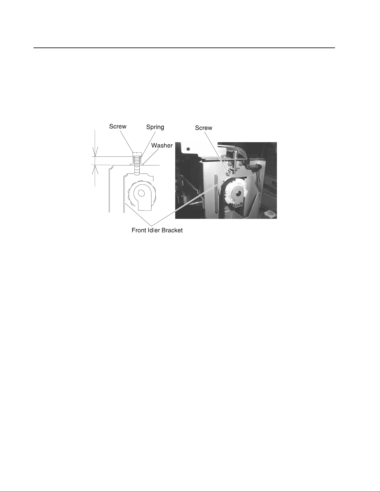
High-capacity paper feed timing belt adjustment
1. Secure the bracket with the screw, as shown.
2. Attach the spring and washer to the bracket with the screw.
3. Adjust the screw to 6mm ±1mm.
4. Tighten the screw completely.
5. Adjust the timing bel t on the rear in the same manner.
Adjustments and procedures following parts replacement
Note: When troubleshooting, or pr ior to making any adjustment to pr int quality, always be sure:
• The printer is installed on a level, rigid surface.
• The photodevelopers are never exchanged. Do not exchange a black photodeveloper for a color
photodeveloper, as they have different surface phase counts.
• The Alignment Page is used when adjusting print registration.
Whenever you replace any of the following parts, be sure to perform the required adjustments or procedures.
The adjustments are in the Repair information and Diagnostic aids chapters.
Printer controller board/printer control EPROM (U7)
If you replace the pri nter controller board, remove EPROM (U7), and install it on the new board. Also check the
printhead alignment.
Printhead controller board
If you replace the pri nthead controller board, replace all the eeproms from the old printhead controller board .
RIP controller board
If you replace the RIP cont roller board, move the memor y, and option cards from the old card to the new one.
4-4 Service Manual
Page 6

5056-XXX
Transfer belt
If you replace the transfer belt, check the printer alignme nt (X, Y, and Theta), adj usted in diagnostic mode .
LED printhead controller board or LED printhead
If you replace the LED printhead controller board or LED printhead, check and adjust the following items in
diagnostic mode:
Printer Alignment (X, Y, and Theta)
Print the alignment pages. Make sure that you install ed the EEPROMS supplied with the printhead on the
printhead cont roller board.
Repair informatio n 4-5
Page 7
5056-XXX
Removals
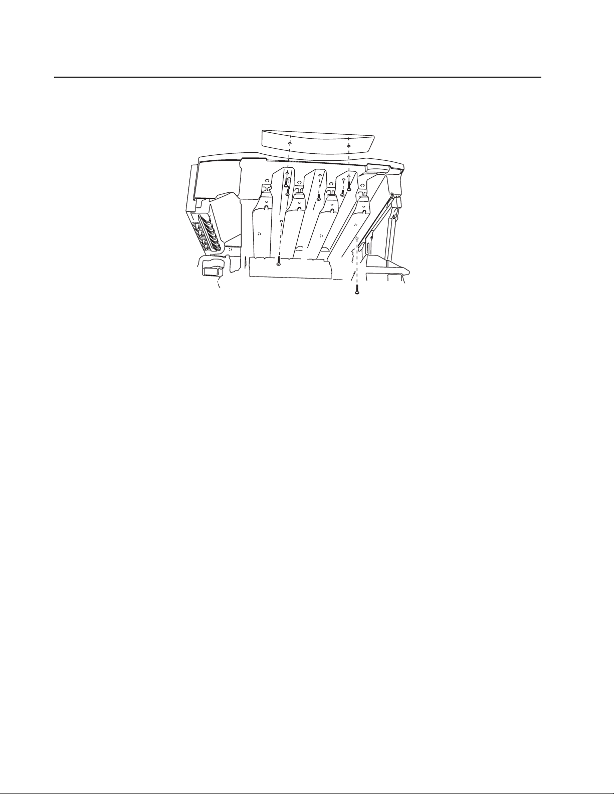
Cover, top removal
1. Open the top unit, and remove the photodevelopers and toner cartridges. Cover the photodevelopers to
avoid damage from exposure to the light.
2. Remove the two silver screws, and remove the spacer.
3. Remove five black scr ews from the bottom and the four si lver screws from the back si de.
4. Remove the top cover.
Note: When replacing the top cover, avoid pinching or cutting wires that connect the printhead controller
board to the face down unit.
4-6 Service Manual
Page 8
5056-XXX
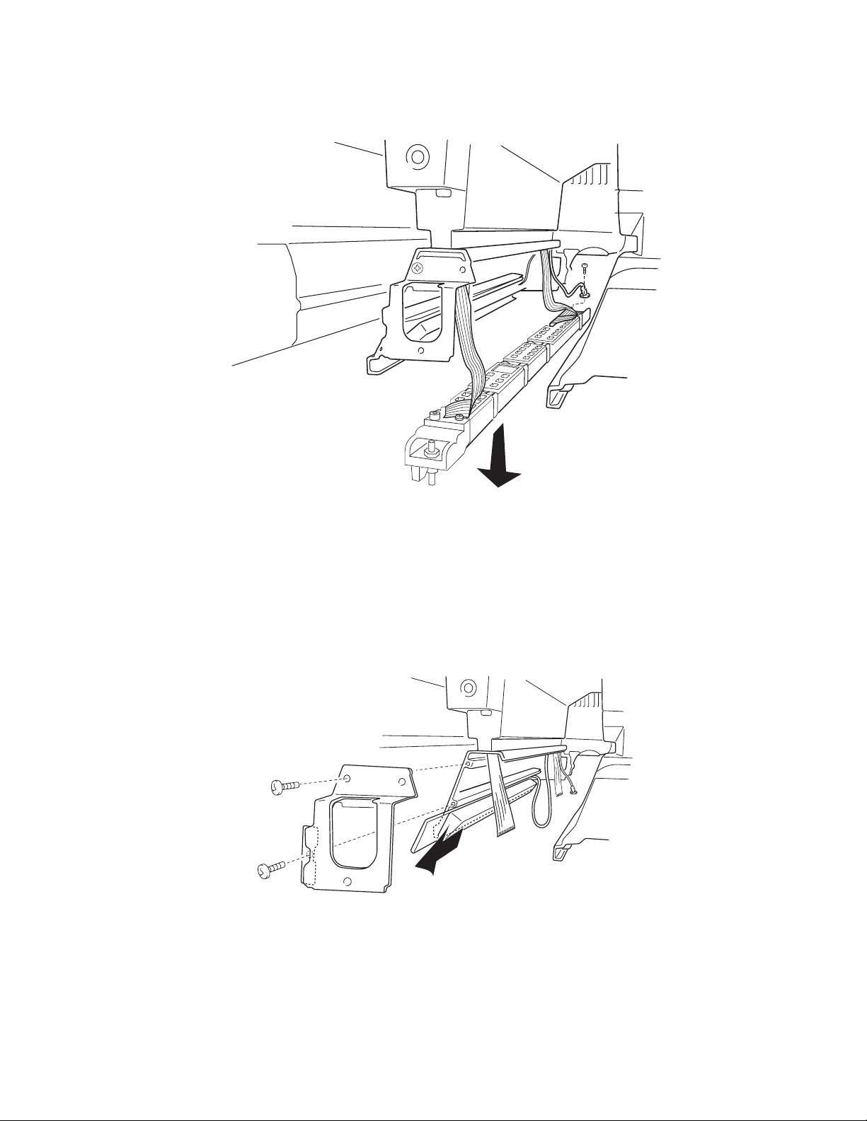
Front door / operator panel removal
Warni ng: If the operat or panel and the RIP board are being replaced at the same time, replace the parts
in the order described in steps a through d below to avoid damage to the machine.
a. Replace the RIP card (this m ust be the first part replaced).
b. Restart the print er. Let the machine finish the startup cycle, which takes sever al minutes. The
machine is silent when startup is complete.
c. Install the new operator panel.
d. Restart the printer and let the startup cycle complete.
If the above proced ure fails, contact the technical support center for further inst ructions.
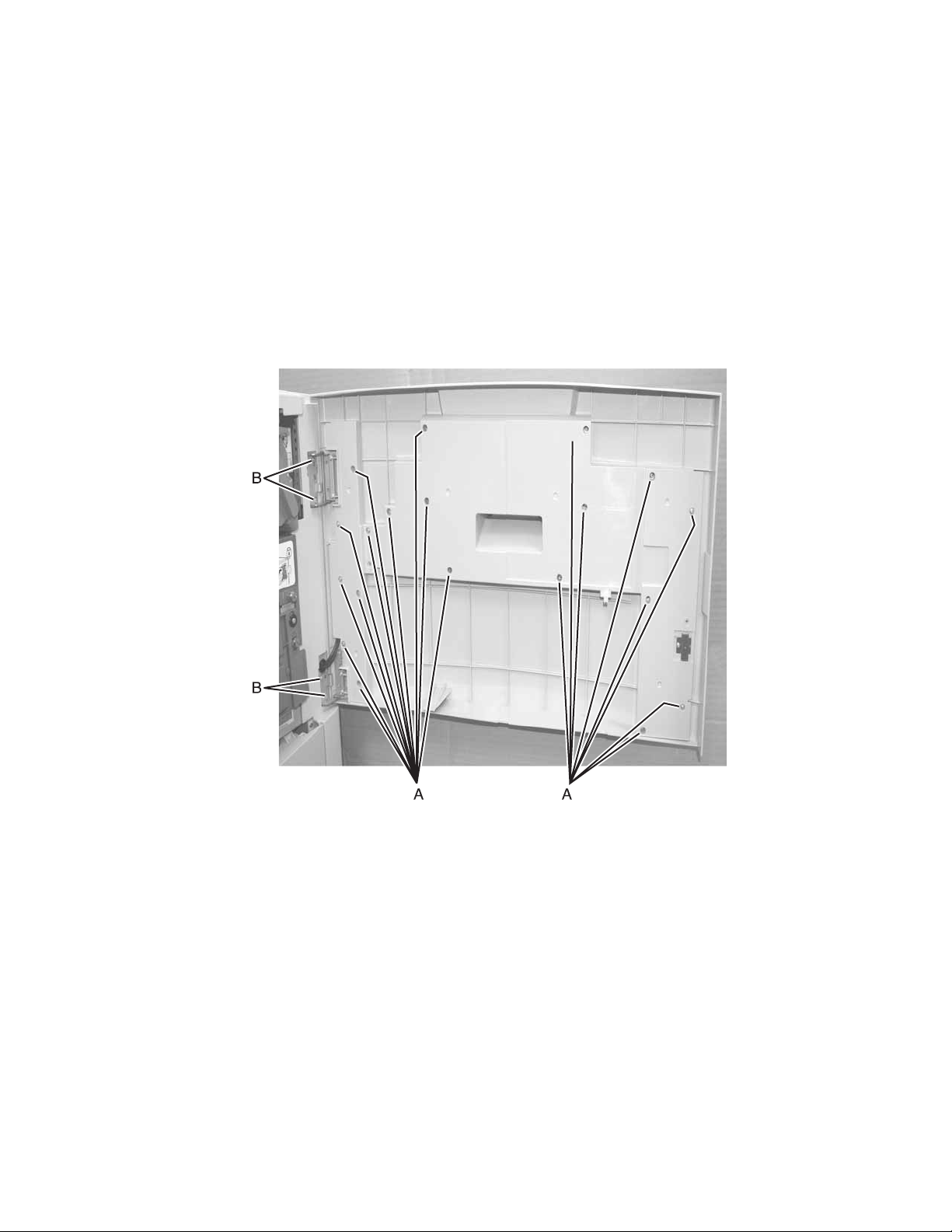
1. Open the front door of the printer.
2. Remove the screws (A) fr om the st iffener bracket.
3. Remove the stif fener bracket.
4. Clip the wire tie that holds the USB and operator panel cables to the door.
Note: Refasten and properly route the cabl es using a wire tie to avoid pinc hing them with the stiffener.
5. Unplug the two cable s fr om the operator panel.
Note: T o continue removing only the operator panel, skip steps 6 and 7
6. Unscrew the four screws (B) that hold the front door moun ti ng brackets to the printer.
7. Remove the front door from the printer.
Repair informatio n 4-7
Page 9
5056-XXX
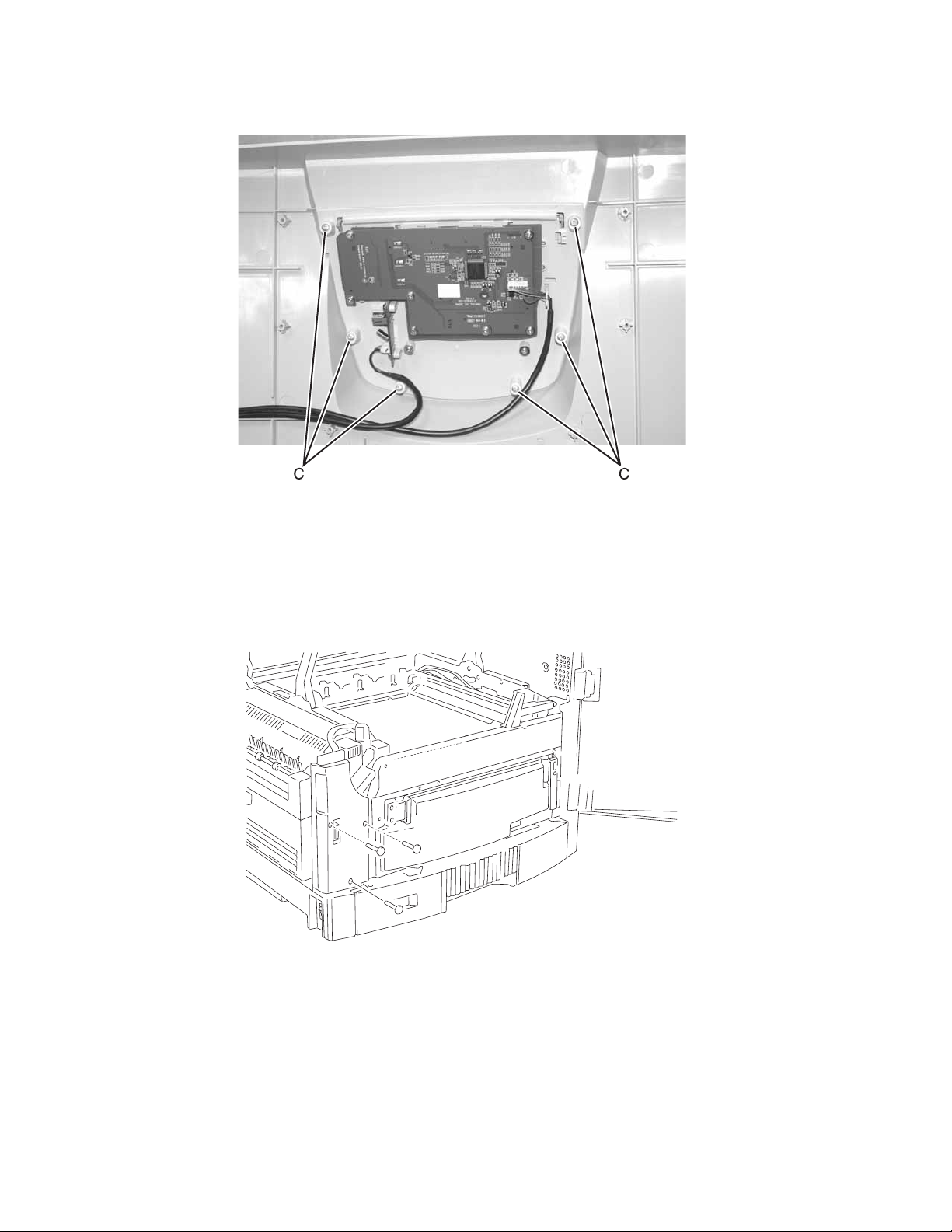
8. Remove six screws (C) that hol d the operator panel to the front door.
9. Remove the operator pan el from the door.
Note: If the USB cable or the operator panel cable is being replaced, use the tor oids from the old cables with
the new cables.
Cover, front left removal
1. Open the front cover and remove the cassette.
2. Remove the left front cover by removing the three silver screws.
4-8 Service Manual
Page 10
5056-XXX
Cover, rear removal
1. Open the top unit.
2. Remove the three silver screws from the rear cover, and then remove the cover.
Cover, solenoid removal
1. Remove the screw from the solenoid cover.
2. Remove the solenoid cover .
Cover, left side removal
1. Remove the upper cassette, front cover, paper exit tray, and duplex unit.
2. Remove the five screws from the left side cover, and remove the cover .
Repair informatio n 4-9
Page 11
5056-XXX
Cover, right side removal
1. Open the top unit, and remove the front cover and upper cassette.
2. Remove the operator panel cable and the USB cable from the operator panel.
(See “Front door / operator panel removal”.)
3. Remove the seven screws fr om the ri ght side cover together with the turn guide, and remove the cover.
4. When installing the right side cover, insert the turn guide shaft into the bearing.
4-10 Service Manual
Page 12
5056-XXX
Cover, RIP board removal
Warning: If the operator panel and the RIP board are being replaced at the sam e time, replace the parts in
this order to avoid dama ge to the machine.
1. Replace the RIP card first (this must be the first part replaced).
2. Restart the p rinter. Let the machine finish th e start up c ycle. This ta kes a few mi nutes. The mach ine is si lent
when sta rt up is com p le te .
3. Install the new operator panel.
4. Restart the print er, and let the startup cycle complete.
If the above proced ure fails, you must cont act the technical suppo rt center for further instructions.
1. Loosen the eight scr ews, and remove the RIP cover by sliding upward.
2. Disconnect all harnesses except for the processor fan (J25) from the RIP board connector.
3. Remove the two screws from the parallel port connecto r and the screw from the USB connector.
4. Remove the eight screws fr om the RIP board together with the parallel connector, and remove the RIP
board.
Note: After replacing any bo ard on the pr inte r , ensure al l the con nect ions ar e properl y connect ed be fore cl osing
the covers.
Repair informatio n 4-11
Page 13
5056-XXX
Tray, paper exit removal
1. Unlatch the hinge at the back side, then unlatch the hinge on the front side.
2. Remove the paper exit tray.
Belt up/down clutch removal
1. Remove the RIP cover, electronic box, printer controller card, and HVPS board.
2. Unplug the belt up/down cl utch cable from CN1 in the CK1 daughte r card board.
3. Remove the C-clip from the bel t up/down clutch, and remov e the cl utch.
4-12 Service Manual
Page 14
5056-XXX
Cassette guide removal
1. Remove the paper feed fram e.
2. Remove the front cover, cassette, turn guide, right side cover , and paper feed frame.
3. Remove the screws from the cassette guide, and rem ove the guide.
CK1 daughter board removal
1. Remove the front, rig ht, left rear, and rear covers.
2. Remove printer controller board and HVPS board.
3. Disconnect all cables from the daughter board.
4. While pinchin g the nyl on standoffs that attach the card to the printer frame, gently pull t he CK1 daughter
board away from the print er frame.
Note: After replacing any bo ard on the pr inte r , ensure al l the con nect ions ar e properl y connect ed be fore cl osing
the covers.
CK2 daughter board removal
1. Remove the front, rig ht, left rear, and rear covers.
2. Remove pow er su pp ly 1.
3. Unplug all cables from the daughter board.
4. Remove four screws from the daughter board, and remove the board.
Note: After replacing any bo ard on the pr inte r , ensure al l the con nect ions ar e properl y connect ed be fore cl osing
the covers.
Repair in fo rmation 4-13
Page 15
5056-XXX
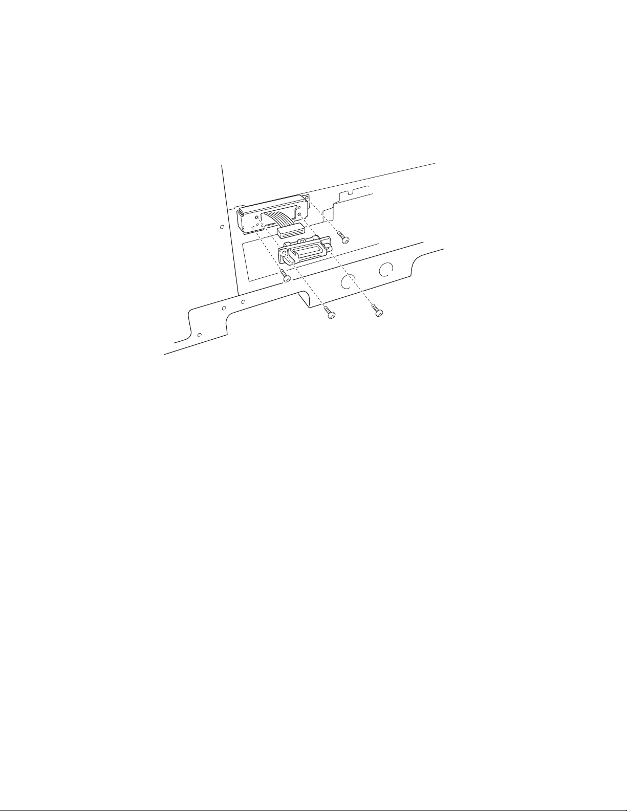
Connector, duplex unit removal
1. Open the top unit and remov e the upper cassette, left f ront cover , paper feed cover, left side cover, RIP
cover, RIP board, RIP box, and the electroni c box. Remove the turn guide, open the paper feed cov er, and
remove the duplex uni t. Remove the left side cover and power supply A.
2. Disconnect the connector, and remove the two screws from the mounting plate.
3. Remove the two screws of the drawer connector from the mounting plate drawer bracket.
Paper tray lift motor removal
1. Remove the front, rig ht, left rear, and rear covers.
2. Remove the cassette.
3. Disconnect the cable from the paper tray lift motor.
4. Remove the three black screws from the paper tray lift motor.
5. Remove the paper tray lif t motor.
4-14 Service Manual
Page 16
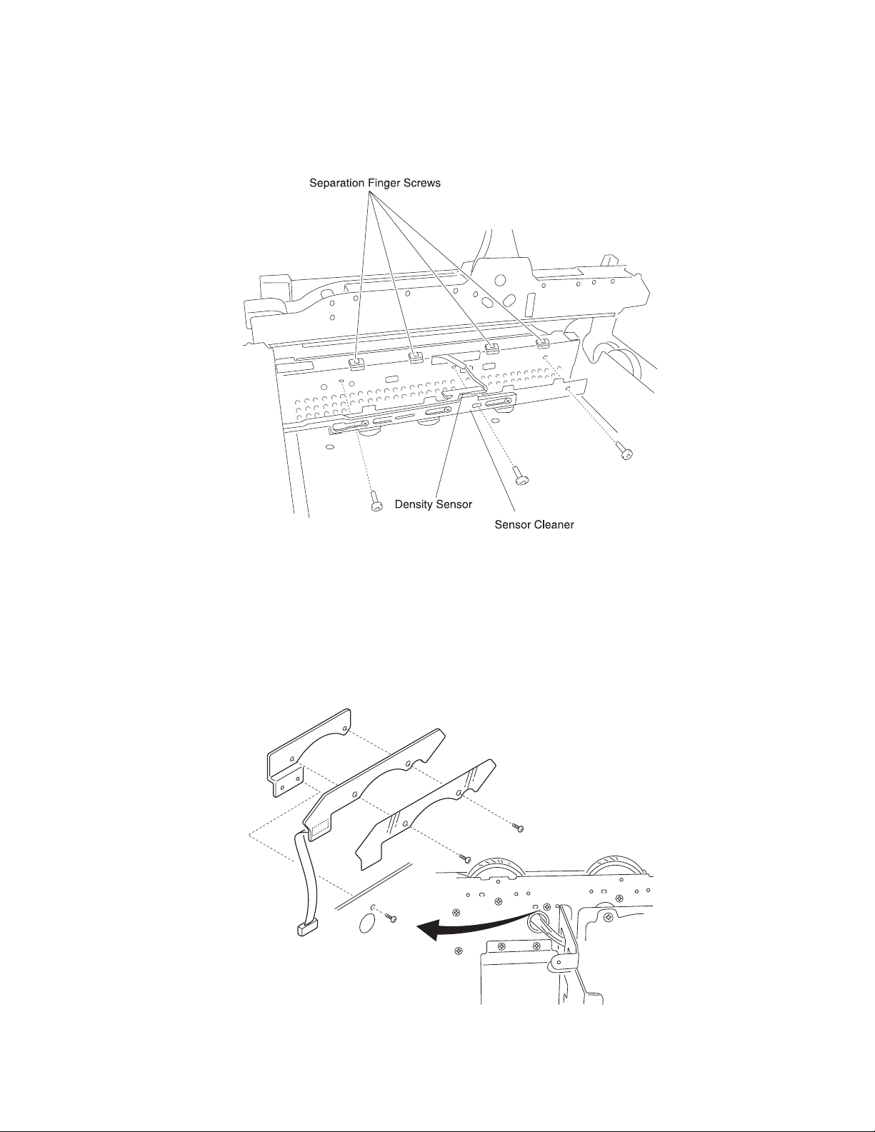
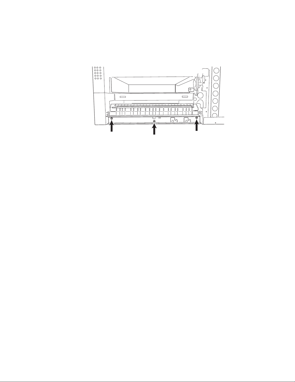
5056-XXX
Density sensor removal/Separation fingers removal/Sensor cleaner removal
1. Open the top unit and remov e the bel t unit.
2. Remove the three screws from the sensor bracket.
3. Remove the harness band and remove the two screws from the density sensor from the sensor bracket.
4. Remove the three set scr ews from the sensor cleaner assembly from the sensor br acket.
5. Remove the four separating finger screws fr om the fuser entrance guide .
Drive gear unit sensor assembly removal
1. Open the top unit, and remove the gear cover, RIP cover, RIP board, RIP box, electronic box, printer
controller, and high voltage power supply board.
2. Remove the screw from the drive gear unit sensor assembly.
3. Remove the two screws of the drive gear unit sensor from the drum drive gear sensor assembly.
Repair in fo rmation 4-15
Page 17
5056-XXX
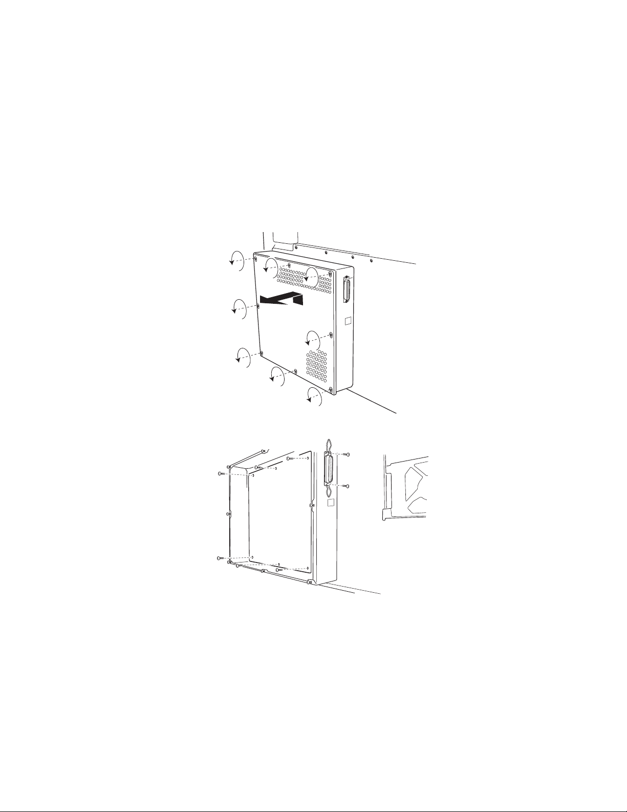
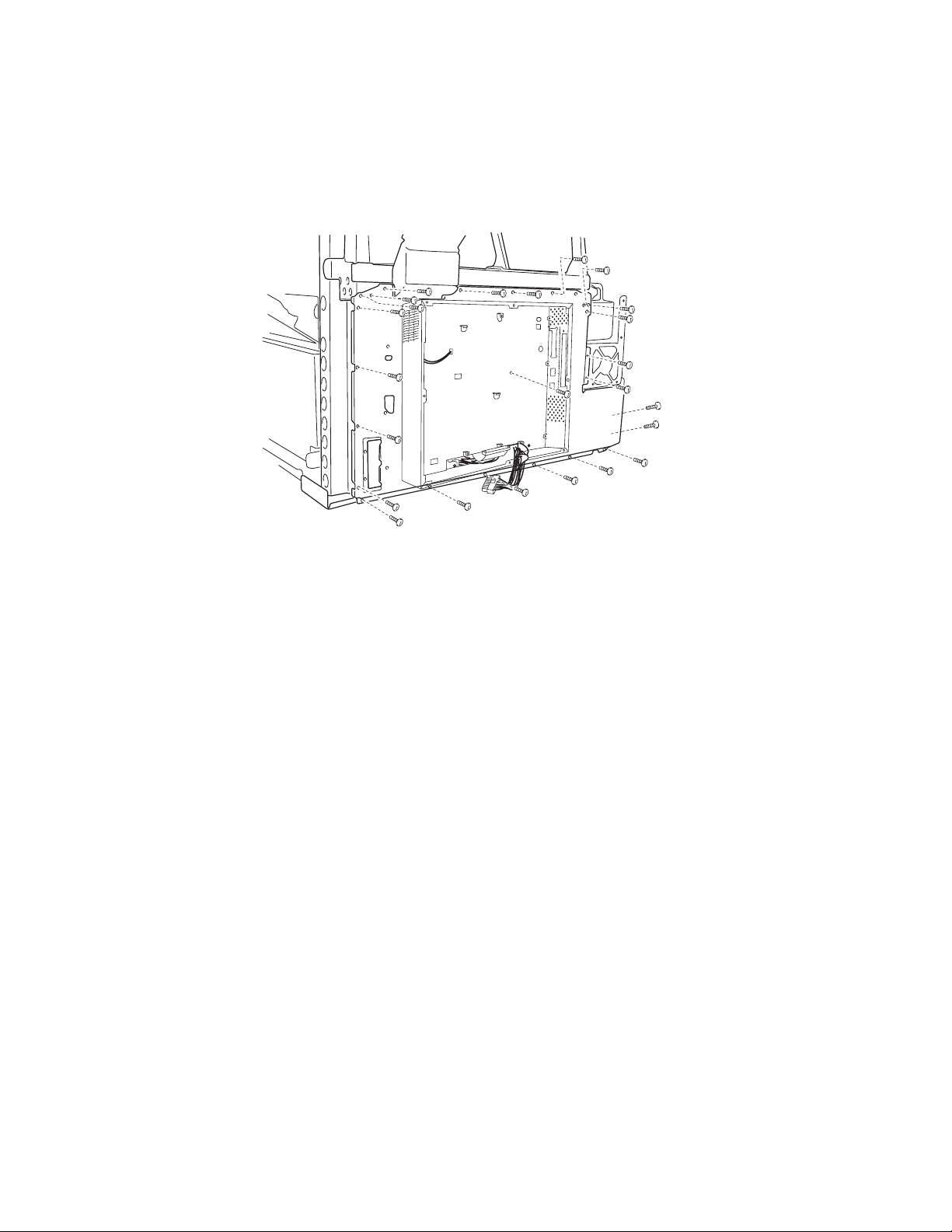
Electronic box removal
1. Open the top unit, and remove the back cover.
2. Remove the RIP board cover.
3. Remove the RIP board.
4. Remove the screws from the electronic box.
5. Disconnect all cables from the rear of the electronic box, and remove the box.
4-16 Service Manual
Page 18
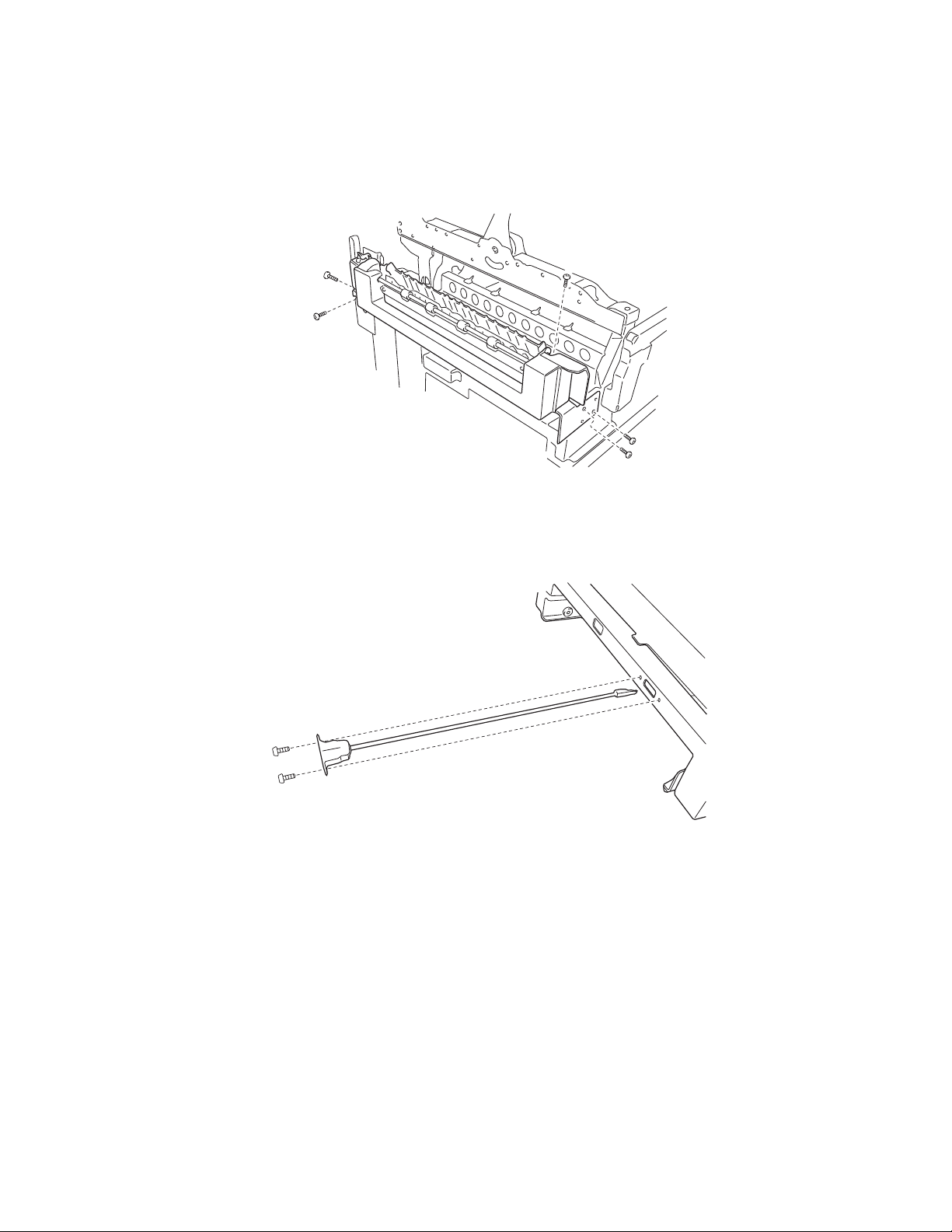
5056-XXX
Face up paper exit assembly removal
1. Open the top unit, and remove the upper cassette. Open the duplex cover, and remove the duplex unit.
2. Remove the left front cover, left side cover, and rear cover.
3. Remove the three screws from the face up delivery assembly, and remove the assembly.
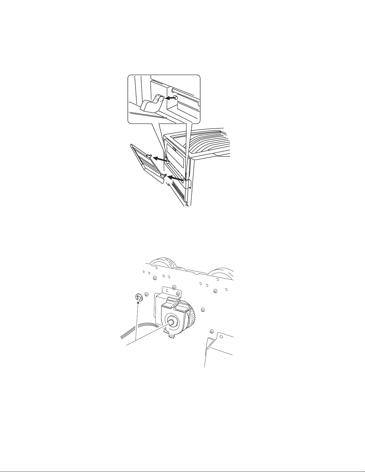
Front cover open switch actuator removal
1. Open the front cover.
2. Remove the two screws from the front cover open switch actuator.
Repair in fo rmation 4-17
Page 19
5056-XXX
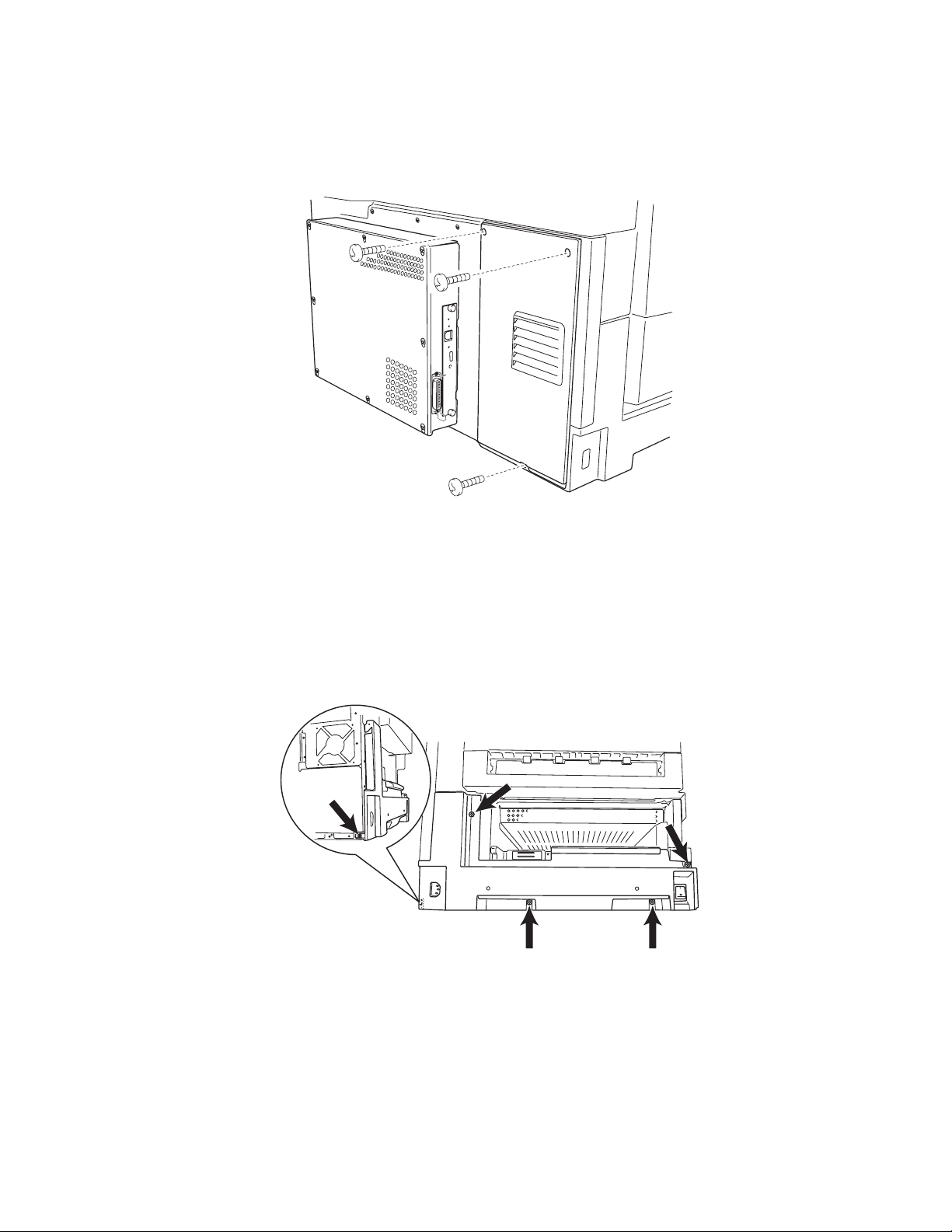
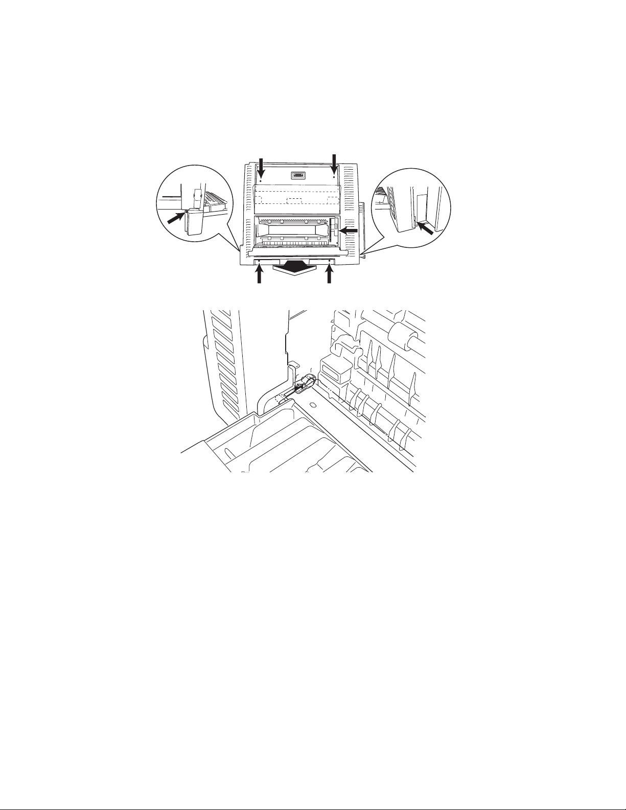
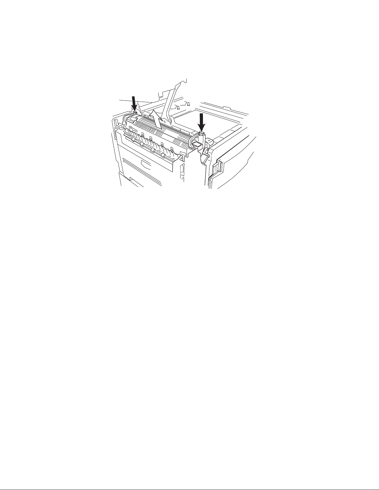
Fuser removal
1. Open the top unit.
2. Pushing the front and back lock, hold the handle, and then raise and remove the fus er.
4-18 Service Manual
Page 20
5056-XXX
Gear cover removal/Multipurpose feeder frame assembly
1. Open the top unit, and remove the upper cassette, front cover, multipurpose feeder, right side cover, and
turn guide.
2. Remove the two screws fro m the gear cover, and remove the cover.
3. Remove the four screws from the multipurpose feed er frame and the ground screw.
4. Disconnect the connector of the multipurpose feeder paper feed sensor.
5. Pull out the multipurpose feeder frame slightly.
6. Remove the screw from the OHP dete ction sensor (upper) .
7. Turn the bearing stopper of the multipurpose feeder roll forward
1/4 turn, and remove upward.
8. Remove the multipurpose feeder frame assembly.
Repair in fo rmation 4-19
Page 21
5056-XXX
High voltage power supply boar d (HVPS) removal
Note: When removing the high voltage power supply , be careful to avoid dama ging the secondary daughter
card (Q906). If the daughter card gets damaged, a 925 service error will result.
1. Open the top unit, and remove the RIP cover, RIP board, RIP box, electronic box, and printer controller
board.
2. Remove the five scre ws from the printer controller board bracket.
3. Remove the connectors, and then remove the 12 screws.
4. Remove the HVPS board.
Note: After replacing any bo ard on the pr inte r , ensure al l the con nect ions ar e properl y connect ed be fore closi ng
the covers.
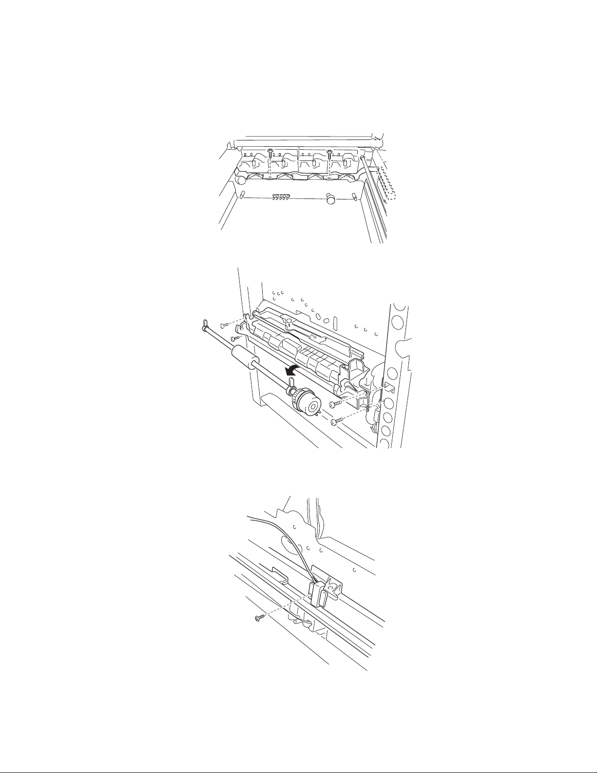
LED printhead removal
1. Open the top unit, remove the top cover , toner cartridges, and photodeveloper drum units.
Note: Remove the transfer belt, or spread a cloth or paper over the transfer belt to p rotect it from dam age.
2. Remove the short black screw from the printhead holder, and remove the holder.
3. Remove the front and rea r printhead springs.
4. Remove the two screws (front and rear) from the right slide rail, and remove the rail.
Note: When replacing the rail, be sure to use the short black screw. A longer screw can interfere with the LED
head causing the image to be out of focus.
4-20 Service Manual
Page 22
5056-XXX
5. Disconnect t he affected LED p ri nthead connector s from the printhea d controller board. Remove the screw
from the ground wire located on the LED printhead.
6. Remove the LED printhead and the cables from the printer.
When replacing the LED prin thead, replace the corresponding EEPROM, shipped with the printhead, on
the printhead contr oller board.
Note: The LED printhead light intensi ty values do not have to be entered for the printer.
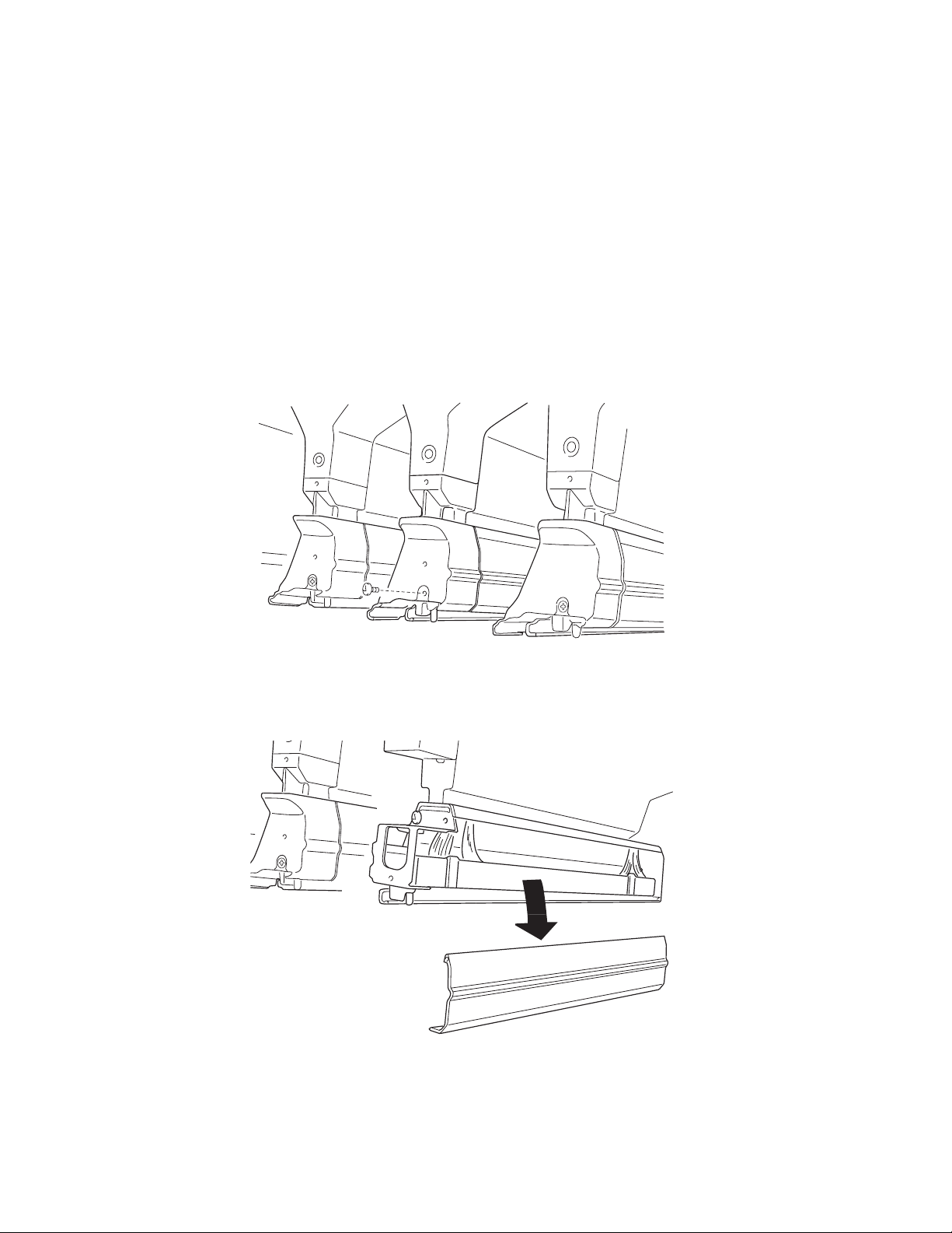
Eraser removal
1. Remove the appropriate printheads (see “LED printhead removal” on page 4-20). Spread a cloth over
the transfer belt to pr otect it from damage.
2. Remove the two screws from HSP holder, and remove the holder.
3. Remove the top cover.
4. Disconnect the eraser cable from the printhead controller boar d.
C–CN06
M–CN05
Y–CN07
K–CN08
5. Carefully thread the eraser cable through the upper unit and remove the eraser.
Repair in fo rmation 4-21
Page 23
5056-XXX
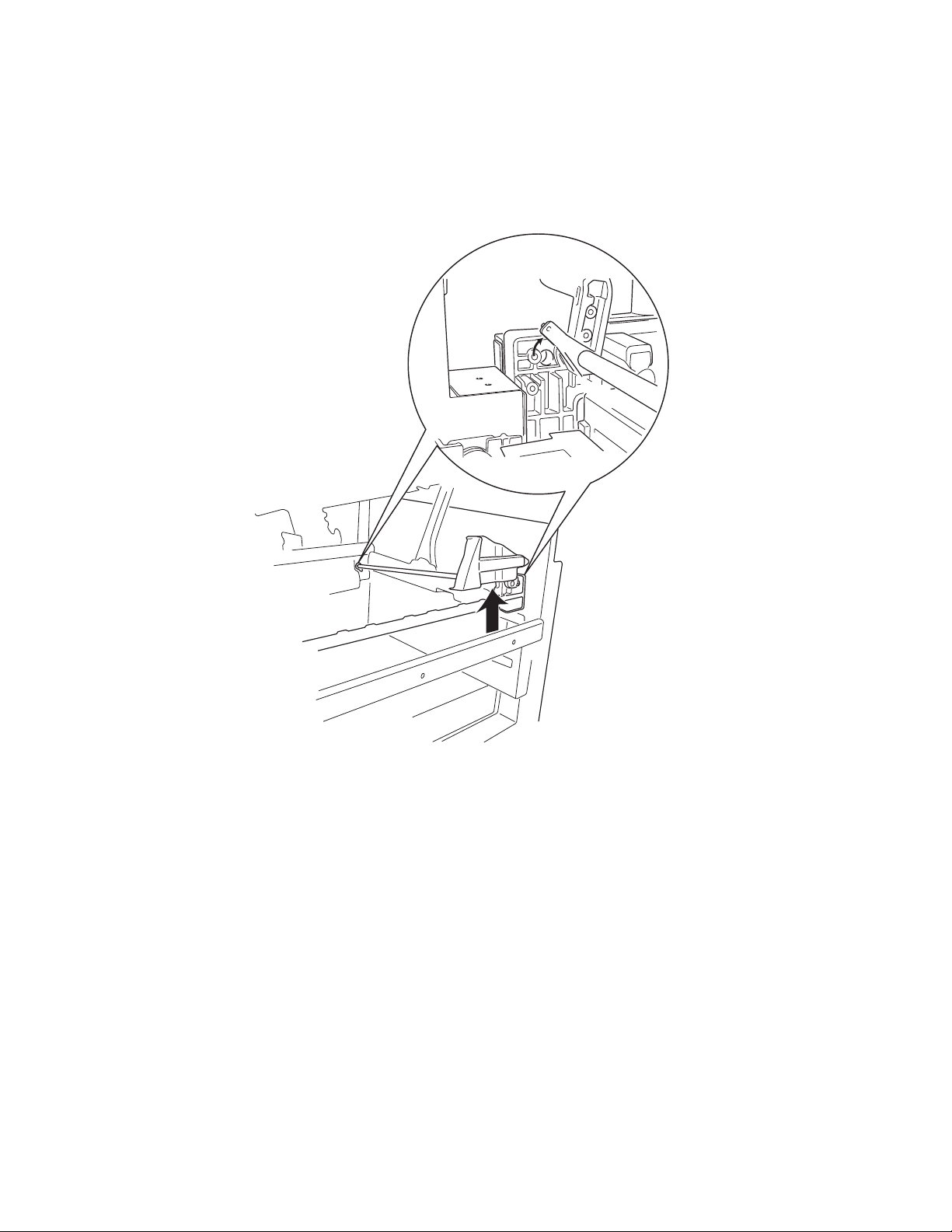
Lock handle assembly removal
1. Open the top unit.
2. Turn the pl astic latch on the front and re ar si des 90°.
3. Remove the spring.
4. Remove the lock handle assembly.
4-22 Service Manual
Page 24
5056-XXX
Main drive unit removal
1. Open the top unit , and remov e th e gear cover, upper cassette, left front cove r, paper feed cover, RIP cover,
RIP board, RIP box, electronic box, and rear cover.
2. Open the turn guide and pape r feed cover , and remove the duplex unit.
3. Remove the left side cover, power unit 1, and power unit 2.
4. Remove the printer controller board.
5. Remove the bracket, HVPS board, and sub frame R.
6. Remove the fuser unit, f ace up paper delivery unit, bel t up/down clutch, and DC drive motor.
7. Remove the multipurpose feeder roll, registration roll, and paper carrying frame.
8. Remove the eight screws from the power supply 2 bracket.
9. Remove the two screws from the belt power supply 2.
10. Remove the two screws from the fan bracket.
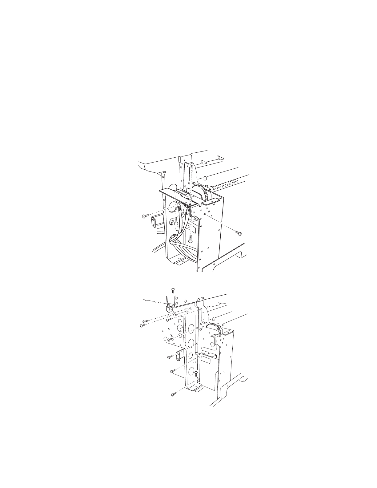
11. Remove the three screws from the fuser connector plate.
12. Remove the two screws of the fuser connector cable assembly from the fus er connector plate.
Note: Note the direction, when installing.
13. After removing the two screws on the bracket that attaches the rear side and paper exit side of the
machine, remove the nine screws from the brack et.
Repair in fo rmation 4-23
Page 25

5056-XXX
14. Remove the screw from the clutch stopper. The clutch stopper is attached to the ground plate with two
screws.
15. Remove the six screws on the right side.
16. Remove the two screws from the drive unit, and remove the unit.
17. Remove the E-clip on the belt up/down clutch, and remove the changing shaft from the drive unit.
18. Remove the three screws from the belt up/down clutc h box, and remove the belt up/down cl utch.
19. Remove the screw from the drum gear sensor, and remove the sensor.
4-24 Service Manual
Page 26

5056-XXX
Main unit fan removal
1. Remove the left side cover, the solenoid cover, and the rear cover.
2. Remove the LVPS (low voltage power supply) 1.
3. Remove two screws from the main unit fan bracket.
4. Disconnect the fan power cable from CN6 on the CK2 daughter card boar d.
5. Remove the fan.
Motor drive board removal
1. Remove the upper cassette, front cover B, paper feed cover, and the left side cover.
2. Disconnect the five connectors, remove five screws, and remove two screws from the motor drive board.
Multipurpose feeder paper present sensor removal
1. Open the top unit and remov e the upper cassette, front cover, turn guide, multip urpose feeder, right side
cover, turn guide, and mult ipurpose feeder fra me .
2. Disconnect the connector and remove the multipurpose feeder paper present sensor.
Repair in fo rmation 4-25
Page 27

5056-XXX
Multipurpose feeder tray removal
1. Open the top unit, and remove the front cover, cassette feeder, turn guides and right side cover.
2. Open the multipurpose feeder and slide it toward the magnet in the direction of the arrow, removing it from
the printer.
Paper feed unit removal
1. Remove the front, rig ht, left rear, and rear covers.
2. Remove the printer cont rol ler board and HVPS board.
3. Unplug connectors CN23, CN16, CN10, CN20, CN12, CN15, and CN7 on the CK1 daughter card board.
4. Remove the e-clip and bushing (A) from the paper feed clutch.
5. Remove four screws (B) from the paper feed gear unit.
4-26 Service Manual
Page 28

5056-XXX
6. Remove the paper feed gear unit, paper feed clutch, and t wo gears (C) not held in place with an E-clip.
7. Remove the 3 screws (D), and remove the cassette gui de.
8. Remove the brass screws (E) on the lef t side of the paper feed unit.
9. Remove the paper feed uni t, being careful to route the sens or cabling through the wire gui des.
Repair in fo rmation 4-27
Page 29

5056-XXX
Paper-feed rollers removal
Paperpath maintenance
A paper path maintenance kit can be used when a machine is expe riencing misfeeds and jams after 200,000
pages. The order number for this kit is 40X1109. The kit is composed of the following parts:
56P9683 Carrying roller
40X1154 Registration fr am e
40X1077 Pickup roll
40X1078 Paper feed roll
40X1079 Separator roll
40X1064 FD paper exit roller
In addition to the paper -path maintenanc e kit, the rel ay roller (40X1108) and turn guide rollers (40X1072) can be
ordered.
Note: This removal can be used for the expansi on paper feed roller remov al. Do not discard the white pl astic
retaining clips. They will be needed to attach the new rollers.
1. Turn off the printer, and unplug the power source.
2. Remove the paper cassette.
3. Pull back on the tab, and remove the pickup roller.
Note: There is a small blue tab on the pickup rol ler.
4. Remove the white plastic retaining clip f rom the shaft, and slide the paperfeed roller (B) off the shaft.
5. Remove the white plastic retaining clip, and slide the separator roller (C) off the shaf t. The torque limiter
(D) can be removed by sli ding off the shaft if i t needs replacement.
4-28 Service Manual
Page 30

5056-XXX
Paper carrying frame removal / roll removal
1. Open the top unit, and remove the upper cassette, front cover, turn guide, multipurpose feeder, right side
cover, turn guide, OHP detection sensor (upper), multipurpose feeder frame, back cover , RIP cover, RIP
board, RIP box, and electronic box.
2. Remove the four screws from the paper carrying fr am e.
3. Remove the paper carry ing frame.
Note: When installing, the clip of the paper carrying clut ch should be securely set to the stop, and the shaft of
the paper-car ryi ng clutch and spring shoul d be securely in contact with one another.
4. Remove the carry clutch and plastic bushing on the left side of the carrying frame.
5. Remove the E-clip and bushing on the right side of the carrying frame.
6. Remo ve t h e ca rrying ro ller.
Repair in fo rmation 4-29
Page 31

5056-XXX
Registration frame
Registration clutch removal
1. Open the top unit, open the t urn guide, open the paper feed cov er, and pull out the duplex unit halfway.
2. Remove the two screws fro m the regi stration frame.
3. Remove the registration clutch.
Note: When installing, set the cli p of the registration clutch to the stopper.
Registration sensor removal
1. Open the top unit, and remove the upper cassette, front cover, turn guide, multipurpose feeder, right side
cover, and multipurpose feeder frame.
2. Disconnect the connector of the registration sensor, and remove the sensor.
4-30 Service Manual
Page 32

5056-XXX
Relay ro ller removal
Note: This removal can be used for the expansi on paper-feed unit relay roller removal as wel l.
1. Remove the paper feed uni t from the machine.
2. Remove the e-clips and bushings from each end of the relay roller shaft.
3. Remove the five screws (A) that hold the top metal plate on the unit.
A
A
4. Remove the top plate from the paper-feed unit.
5. Slide the relay roller to the right (B), and til t t he roller up and out of the unit.
B
C
6. Pull the relay roller to the left (C), and remove the roller from the paper-feed unit.
Repair in fo rmation 4-31
Page 33

5056-XXX
Face down guide assembly removal
1. Remove the top cover.
2. Disconnect the connector, and remove the five screws and two snap bands from the face down guide
assembly.
3. Remove the four screws from the face down cover and the face down gui de assembly, and remove the
assembly.
Note: When replacing the face down unit, use a ti e to hol d back the wiring that connects the printer controller
board to the face down unit. Avoid pinching or cutti ng wiring that connects the face down unit to the printhead
controller board.
Face down exit roll removal
Note: When replacing the face down exit roll er, lubricate the ends of the roller shaft wit h a sma ll am ount of
Nyogel 744 (part number 40X0179). Open the top unit, and remove the toner cartridges, photodeveloper drum
units, and upper cover.
1. Remove the face down unit from the printer .
2. Remove the three screws (A) that hold the rear cover to the face down unit.
4-32 Service Manual
Page 34

5056-XXX
3. Remove the rear cover.
4. Remove the motor and driv e belt fr om the exi t roller shaft.
5. Remove the grounding st rip (A).
Repair in fo rmation 4-33
Page 35

5056-XXX
6. Remove the e-clips and bushings (A) from both ends of the exit roller shaft.
7. Pull the guide rib (A) to t he lef t.
4-34 Service Manual
Page 36

5056-XXX
8. Remove the exit roller.
Power supply 1 removal
1. Unplug the power cord from th e pri nter.
2. Open the top unit, and remove the RIP cover, RIP board, RIP box, and electronic box. Remove the
cassette, l eft front cover, and back cover. Remove the left side cover .
3. Remove the insul ation sheet con nect or, yellow ground wire, five screws , two scr ews wit h washe rs, and t wo
screws with spring washers.
4. Disconnect CN106 and CN04 at power supply 2.
5. Remove the power supply.
Note: When installing, incli ne the ground wire by 45°.
Note: After replacing any bo ard on the pr inte r , ensure al l the con nect ions ar e properl y connect ed be fore cl osing
the covers.
Repair in fo rmation 4-35
Page 37

5056-XXX
Power supply 2 removal
1. Unplug the power cord from th e pri nter.
2. Open the top unit, and remove the RIP cover, RIP board, RIP box, and electronic box.
3. Disconnect the connector, and remove the seven sc rews f rom power supply 2, and remove the power
supply.
Note: After replacing any bo ard on the pr inte r , ensure al l the con nect ions ar e properl y connect ed be fore closi ng
the covers.
Note: Before installing the new power sup ply, remove the black actuator guid e (A) f rom the old power supply
and install it on the new power supply.
4-36 Service Manual
Page 38

5056-XXX
Power switch removal
1. Remove the upper cassette, left front cover, paper feed cover, and left side cover.
2. Unlock the power switch, and pull out the power switch.
3. Remove each terminal connected to the power switch.
Note: When connecting, be careful to connect the connectors correctly. Insert the insulator cover, completely
covering the terminal.
Printer controller removal
1. Open the top unit, and remove the RIP cover, RIP board, RIP box, and electronic box.
2. Remove the co nnector s and th e sc rews fr om the pr inter co ntrolle r . Pay attent ion t o the l ocati on, or label the
two pin connector s when removing them from the board to avo id reconnection into the wrong location.
When replacing the board, install the EPROM (U7) of the former board to the new board. Also, when
replacing the EPROM, set th e li ght intensity in the diagnostic mode, and set th e counter and printer
alignment.
Note: After replacing any bo ard on the pr inte r , ensure al l the con nect ions ar e properl y connect ed be fore cl osing
the covers.
Repair in fo rmation 4-37
Page 39

5056-XXX
Printhead controller board removal
1. Remove the top cover, and then remove the 20 printhead controller board connectors.
2. Remove the six screws fr om the pr inthead controll er board and remove the board.
Note: When replacing the board, be sure to return the four EEPROMs on the former board to the same
positions on the new board.
4-38 Service Manual
Page 40

5056-XXX
Left slide rail removal
1. Remove the upper cassette.
2. Remove the screw from both left and right slide rails.
RIP box removal
1. Remove the six screws from the RIP box.
2. Slightly lift and remove the RIP box.
Repair in fo rmation 4-39
Page 41

5056-XXX
Sensor board removal
1. Remove the transfer belt unit.
2. Remove the four connect ors.
3. Remove the three screws from the waste toner full sensor board.
Stay arm removal
1. Open the top unit, and remove the face down paper guide assembly.
2. Remove the yellow and bla ck sub frame.
3. Remove the screw from the right stopper, and remove the stopper.
4. Remove the screw from the left stopper, and remove the stopper.
5. Remove the clip from the lock shaft.
6. Remove the 17 screws from the stay arm, and remove the arm.
4-40 Service Manual
Page 42

5056-XXX
Sub-frame removal
Important: Read the entire procedure before removal.
1. Open the top unit, and remove the RIP cover, RIP board, RIP b ox, electronic b ox, printer control ler, printer
controller bracket, and HVPS board.
2. Remove the cable ties.
3. Remove the 12 screws from the sub frame.
4. Remove sub frame.
Repair in fo rmation 4-41
Page 43

5056-XXX
Sub frame F1, sub frame F2 removal
1. Open the top unit.
2. Remove the two screws fro m the sub fr am es F1 and F2.
Note: Spread a paper or cloth over the belt to protect the belt. Set the sub frame F to the position of the
following colors, depending on the presence of the upper detection buttons.
Magenta Sub frame F1 Detection button available
Cyan Sub frame F2 Detection button unavailable
Yellow Sub frame F1 Detection button unavailable
Black Sub frame F2 Detection button available
Temperature /hu midi ty sensor removal
1. Remove the rear cover, printer controller board, and HVU board.
2. Disconnect the cable from connector on the temperature humidity sensor.
3. Remove the screw (A) holding the sensor to the paperfeed gear linkage.
4. Remove the temperatur e/humidity sensor.
4-42 Service Manual
Page 44

5056-XXX
Top unit removal
1. Open the top unit, and remove the top cover and face-down guide assembly.
2. Remove the screws, and remove the top unit.
Transfer belt removal
Transfer belt removal has been simplified with a redesign of the changing shaft linkage to the belt up / down
clutch. The supplies menu no longer needs to accessed to remove the transfer belt unit.
Note: If the operator panel is inoperable, or if you have an unrecovera ble error code, t his procedur e can still be
used.
1. Turn the printer off, alon g wit h any optional devices conn ected to the printer.
2. Open the front cover and top unit.
Warning: Do not touch , d rop, or pl ace anythi ng on t he transf er bel t. Touching the surf ace of the tr ansfer belt or
placing items on the bel t may cause damage.
Repair in fo rmation 4-43
Page 45

5056-XXX
3. Loosen the thumbscrews as shown.
4. Lift and remove the transfer belt cover.
4-44 Service Manual
Page 46

5056-XXX
5. Loosen the thumbscrews as shown.
6. Press down on the transfer belt release lever as shown.
Repair in fo rmation 4-45
Page 47

5056-XXX
7. Pull the transfer belt out.
8. After replacing the transfer belt and re mo ving the four shipping spacers, tighten the transfer belt
thumbscrews, and reinstall the tran sfer belt cover.
9. Close the top unit, r otate the locking lever to the ri ght, and close the front cover.
10. Turn the printer on.
11. Adjust the registration, if needed, by pressing the Menu key, scrolling to Settings, scrolling to Utilities, and
selecting Alignment Info. From here, you can adjust the settings for the belt. Print an alignment page to
confirm that the bel t is properly adjusted. Perform further adjustments if needed.
Note: The belt adjustment can be adversel y affected by a toner low condition.
4-46 Service Manual
Page 48

5056-XXX
Turn guide cover sensor removal
1. Remove the left rear, rear, and right covers.
2. Remove the print contro ller card and the HVPS.
3. Disconnect the sensor cable from CN10 on the CK1 daughter card board.
4. Remove two screws from the t urn guide sensor assembl y, and remove the sensor.
Upper fan removal
1. Open the top unit, and remove the toner cartridges and photodeveloper drum units, top cover, and face-
down guide assembly.
2. Remove the four screws and the fi ve screws from the upper brack et, and remove the bracket.
Repair in fo rmation 4-47
Page 49

5056-XXX
3. Remove the two screws from the left fan, and remove the fan.
4. Remove the two screws from the right fan, and remove the fan.
4-48 Service Manual
Page 50

5056-XXX
Expansion feeder removals
Turn guide door removal
1. Open the turn guide door.
2. Pull the door hinge fr om the right turn guide bushing.
3. Pull the turn guide door clear of the expansion fe eder.
Expansion fee der cont roller board removal
1. Remove six screws from the expansion feeder rear cover.
2. Unplug all cables from the expansion feeder controller board.
3. Remo ve six scr e w s from the controlle r c ard.
4. Remove the control ler board.
Note: After replacing any bo ard on the pr inte r , ensure al l the con nect ions ar e properl y connect ed be fore cl osing
the covers.
Size sensor board removal
1. Remove the expansion feeder controller boar d.
2. Remove two screws on the size sensor board.
3. Remove the size sensor board.
Repair in fo rmation 4-49
Page 51

5056-XXX
Stepper motor removal
1. Remove the expansion feeder rear cover.
2. Disconnect the stepper motor power cable fr om the expansion feeder con tr oller board.
3. Remove three screws fr om the stepper motor assembly (A).
A
4. Remove the stepper motor assembly from the expansi on feeder.
4-50 Service Manual
Page 52

5056-XXX
Paper feed assembly removal
1. Remove the rear cover.
2. Remove the cassette.
3. Remove the stepper motor assembly.
4. Disconnect the cables from connectors CN11, CN13, CN18 on the expansion feeder controller board.
5. Remove the screws (A) hol ding the paper feed gear assembl y.
6. Remove the gear assembly (B) and the paper feed clutch (C).
7. Remove three gears fr om the paper feed unit.
E
D
8. Remove the three cassette guide screws (D).
9. Remove three screws (E)
10. Remove three screws from the left side of the paper feed unit (F).
11. Feed the sensor cables through the side. Use care to avoid damaging the insulation.
12. Gently lift the paper feed unit out of the expans ion feeder .
Repair in fo rmation 4-51
Page 53

5056-XXX
Paper tray lift motor removal
1. Remove the rear cover.
2. Remove the cassette.
3. Disconnect the cable from the paper tray lift motor.
4. Remove three black screws from the paper tray lift motor (A).
A
5. Remove the paper tray lif t motor.
Expansion feeder turn guide door sensor assembly removal
1. Remove the rear cover.
2. Disconnect the cable from CN15 on the controller boar d.
3. Open the turn guide door.
4. Remove two black screws from the door sensor.
5. Thread cable, avoid fraying insulation, through side frame, and remove the sensor.
4-52 Service Manual
Page 54

5056-XXX
Duplex removals
Duplex unit separation removal
1. Remove the thumbscrews, C-clips, and scr ews as shown from both sides.
2. Remove the connectors, and separate the duplex frame from the duplex unit.
Repair in fo rmation 4-53
Page 55

5056-XXX
Duplex unit removal
1. Remove the four screws from the interface board , and re mo ve the board.
2. Remove the two screws fro m the duplex connector, and remove the con nector.
Duplex timing belt removal
1. Remove the three C-clips from the three timing gears, and remove the timing belts.
2. Remove the knob screw, and remove the timing bel t.
4-54 Service Manual
Page 56

5056-XXX
Duplex pressure roller and solenoid removal
Remove the two screws securing the pressure roller solenoid assembly.
Duplex feed roller and solenoid removal
1. Remove the two screws securing the feed roll solenoid assembly.
2. Remove the pressure roller and springs.
3. Remove the feed roller and springs.
Repair in fo rmation 4-55
Page 57

5056-XXX
Duplex side fence motor assembly/side fence removal
1. Remove the three screws, and remove the side fence motor assembly.
2. Remove the front and rea r si de fences.
Note: When installing, spread the front and rear side fences to the sides, and install.
4-56 Service Manual
Page 58

5056-XXX
Duplex paper carrying motor removal
1. Remove the gear cover.
2. Remove the screws from the duplex paper carrying motor, and remove the motor.
Repair in fo rmation 4-57
Page 59

5056-XXX
High-capacity feeder (HC F ) removals
HCF covers removal
1. Remove the two screws fro m the dri ve cover, and remove the cover.
2. Remove the front cover.
3. Remove the two screws from the right cover, and remove the cover.
4. Remove the top cover.
5. Remove the rear cover.
6. Remove the four screws from the transfer cover, and remove the cover.
4-58 Service Manual
Page 60

5056-XXX
HCF call roller, paper feed roller, reverse roller removal
1. Open the top cover on the tray.
2. Remove the two screws fro m the transfer cover, and remove the cover.
3. Remove the retaining ri ngs on the rollers, and remove the rollers.
HCF pickup solenoid removal
1. Remove the four screws from the transfer cover, and remove the cover.
2. Remove the two screws fro m the dri ve cover, and remove the cover.
3. Remove the screw from the clam p plate, and remove the plate.
4. Remove the connector and the two screws from the pickup sol enoid, and remove the solenoid.
Repair in fo rmation 4-59
Page 61

5056-XXX
HCF paper end sensor removal
HCF paper size sensors (1, 2) removal
1. Cover the paper level sensor with your hand, and pres s the down button. The tray m oves down. Lower the
tray until the down sensor turns on.
2. Remove the front cover and tr ansfer cover.
3. Remove the two screws on the front and rear sides of the side fence.
4. Mark the locking position of the side fenc e locking stay.
5. Remove the two screws on the si de fence locking stay.
6. Remove the screw and connector from paper end sensor, and remove the sensor.
7. Remove the screw and connector from the clamp plane, and remove the paper size sensors 1 and 2.
Notes:
• To prevent damage to the stay, hold the stay when removing the sensors.
• Be sure the sid e regis tration is not s hift ed, whic h may oc cur with t he dism ounti ng and mo unting o f the
locking stay. If it is shifted, relocate the stay toward the front or rear to adjust.
4-60 Service Manual
Page 62

5056-XXX
8. Remove the top cover switches.
Top Cover Switch 1
Blue
HCF tray motor removal
1. Remove the rear cover and t he dri ve cover.
2. Remove the two screws of the tray motor, and remove the motor.
Blue
Black
White
Green
Yellow
Top Cover Switch 2
Repair in fo rmation 4-61
Page 63

5056-XXX
HCF paper level sensor removal
1. Remove the four screws from the transfer cover, and remove the cover.
2. Remove the two screws from the sensor, and remove the cover.
3. Remove the connector and screw from paper level sensor, and remove the sensor.
HCF power supply removal
1. Move the paper tray upwar d.
2. Disconnect the power cord.
3. Remove the front cover.
4. Remove the two screws from the power supply cover, and remove the cover.
5. Remove the four screws from the power supply unit, and remove the unit.
6. Remove the two screws from the DC-DC converter, and remove the converter.
4-62 Service Manual
Page 64

5056-XXX
Finisher r emovals
Note: Check finisher alignment when moving or servicing the finisher. After moving or servicing the finisher,
print some test pages to the finisher to ensure t he vertical and horizontal alignment is correct. If the finishe r is
not properly ali gned, refer to “Aligning the finisher and printer” on page 3-59 for alignment instructions.
External covers removals
1. Remove the finish er tr ays.
2. Remove the two screws fro m the front cover, and remove the cover.
3. Remove the two screws from the rear cover, and remove the cover.
Repair in fo rmation 4-63
Page 65

5056-XXX
4. Remove the two screws from the top cover, and remove the cover.
Finisher control board removal
1. Remove the external covers.
2. Disconnect all of the associated connectors.
3. Remove the four finisher control board mount ing screws, and remove the boar d.
4-64 Service Manual
Page 66

5056-XXX
Elevator motor removal
1. Disconnect the elevator motor connector.
2. Remove the two elevator motor bracket screws from the bracket.
3. Remove the elevator motor assembly.
Feed motor assembly removal
1. Remove the finish er control board mountin g bracket.
2. Loosen the tensio n b racket mounting screw.
3. Disconnect the feed motor connector.
4. Remove the three screws and connector from the feed moto r mounting brack et, and remove the feed motor
assembly.
5. Remove the feed motor pulley.
Repair in fo rmation 4-65
Page 67

5056-XXX
Hole punch removal
1. Remove the external covers.
2. Remove the hole punch unit cables.
3. Remove the tension spr ing.
4. Remove the screw and E-ring from the tension bracket , and remove the bracket.
Note: When installing the tension bracket, use the left side screw hole for the three hole punch unit and
the right side scr ew hole for the four hole punch unit .
5. Remove the two hole punch unit screws, and remove the unit.
4-66 Service Manual
Page 68

5056-XXX
Inverter paper exit discharge brush removal
1. Remove the external covers.
2. Remove the finish er control board.
3. Remove the upper left panel.
4. Remove the two discharge brush screws, and remove the brush.
Inverter paper exit rol ler removal
1. Remove the front and rea r ext ernal covers.
2. Remove the four lower left panel screws, and remove the panel.
3. Disconnect the harness connect from the lower left panel.
4. Remove the inverte r paper exit roller bushi ng.
Repair in fo rmation 4-67
Page 69

5056-XXX
5. Remove the inverte r id le gear.
6. Remove the inverte r drive gear and bushing.
7. Remove the inverte r paper exit roller.
Jogging unit removal
1. Remove the dust box.
2. Remove the two screws, and r emove the cover.
3. Disconnect the jogging motor connect or.
4. Disconnect the jogging home position sensor connector.
5. Remove the jogging unit.
4-68 Service Manual
Page 70

5056-XXX
Path select gate removal
1. Remove the external covers.
2. Remove the two screws from the top cover, and remove the cover.
3. Remove the gate solenoid with mounting bracket .
4. Remove the straight paper exit sensor connector.
5. Remove the upper guide pl ate for the straight paper exit .
6. Remove the two screws and two spr ings for the upper guide plate.
7. Remove the path select gate.
Note: Adjust the solenoid bracket mounting position so that the gate arm is contacti ng the solenoid.
Repair in fo rmation 4-69
Page 71

5056-XXX
Patting roller removal
1. Remove the front and rea r covers.
2. Remove the finish er control board mountin g bracket.
3. Remove the two screws from the upper left panel, and remove the panel.
3
4. Disconnect the sensor connector.
5. Remove the sensor harness from the harness clamp.
6. Remove the four upper guide plate screws from the invert er paper exit, and remove the plat e.
7. Remove the four screws from the inverter guide plate, and remove the plate.
4-70 Service Manual
Page 72

5056-XXX
8. Remove the tension spr ings. Use the upper hole when instal ling the spring.
9. Remove the gear and bushing.
10. Remove the patting roller.
Patting
Roller
Repair in fo rmation 4-71
Page 73

5056-XXX
Power supply removal
1. Unplug the power cord from th e pri nter.
2. Remove the external covers.
3. Remove the lower left panel.
4. Remove the cable connector for the left panel .
5. Remove the four lower guide support plate screws, and r em ove the plate.
6. Remove the two power supply screws.
7. Remove the screw from the ground wire.
8. Disconnect the power supply connector, and remove the power supply.
4-72 Service Manual
Page 74

5056-XXX
Registration roller removal
1. Remove the hole punch unit.
2. Remove the registration roller clutch.
3. Remove the registration roller bushing.
4. Remove the registration roller.
Registration roller clutch removal
1. Remove the harness fro m the clamp.
2. Remove the three control board mounting bracket screws, and remove the bracket.
3. Remo ve t h e reg istra tion rol l er clut ch se t scre w.
4. Remove the registration roller clutch connector.
5. Remove the registration roller clutch.
Repair in fo rmation 4-73
Page 75

5056-XXX
Stack area discharge brush removal
1. Remove the dust box.
2. Remove the stack area di scharge brushes.
Staple unit removal
1. Remove the staple uni t connector .
2. Pull outward on the stapl e cover, and remove the staple unit.
4-74 Service Manual
Page 76

5056-XXX
Straig ht pa p er ex it di sc ha r ge br ush re mo va l
1. Remove the external covers.
2. Remove the two screws from the top cover, and remove the cover.
3. Remove the two lever screws, and remove the lever.
4. Remove the two discharge brush screws, and remove the brush.
Straig ht pa p er ex it ro l ler removal
1. Remove the external covers.
2. Remove the finish er control board.
3. Remove the upper left panel.
4. Remove the front straight paper exit roll er bushing.
5. Remove the belt and pulley.
Repair in fo rmation 4-75
Page 77

5056-XXX
6. Remove the rear straight paper exit roller E-ring and bushing.
7. Remove the straigh t paper exit roller.
4-76 Service Manual
Page 78

5056-XXX
Timing belts 1 and 2 removal
1. Remove the finish er control board mountin g bracket.
2. Remove the feed motor mounting bracket.
3. Remove the tension bra cket mounting screw.
4. Remove the tension spr ing.
5. Remove the timing belt 1.
6. Loosen the tension bracket mounting screw for timing belt 2.
7. Remove the timing belt 2.
Repair in fo rmation 4-77
Page 79

5056-XXX
Tractor belt removal
1. Remove the external covers.
2. Remove the lower left panel.
3. Remove the cable connector of the left panel.
4. Remove the belt motor unit.
5. Remove the four lower guide support plate screws for the invert paper exit.
6. Remove the tension spring from the shaft.
7. Remove the paper jam removal knob.
4-78 Service Manual
Knob
Page 80

5056-XXX
8. Remove the tractor belts.
Note: Install the belt so that the belt tooth just under the plast ic hook aligns with the hook on the other belt.
Tractor drive motor assembly removal
1. Remove the outer covers.
2. Remove the drive belt.
3. Remove the three screws , and disconnect the connector from the tractor drive motor assembly.
4. Remove the tractor dri ve m otor assembly.
Repair in fo rmation 4-79
 Loading...