

Page 1

Lexmark™ C720
Color Laser Printer
Machine Type 5024-001
Parts Catalog Guide
Lexmark and Lexmark with diamond
design are trademarks of Lexmark
International, Inc., registered in the
United States and/or other countries.
Page 2

5024-001
Parts Catalog
How to Use this Parts Catalog
• SIMILAR ASSEMBLIES: If two assemblies contain a majority of
identical parts, they are shown on the same list. Common parts
are shown by one index number. Parts peculiar to one or the
other of the assemblies are listed separately and identified by
description.
• AR: (As Required) in the Units column indicates that the
quantity is not the same for all machines.
• NP: (Non-Procurable) in the Units column indicates that the part
is non-procurable and that the individual parts or the next higher
assembly should be ordered.
• NR: (Not Recommended) in the Units column indicates that the
part is procurable but not recommended for field replacement,
and that the next higher assembly should be ordered.
• R: (Restricted) in the Units column indicates that the part has a
restricted availability.
• NS: (Not Shown) in the Ref column indicates that the part is
procurable but is not pictured in the illustration.
• PP: (Parts Packet) in the Description column indicates that the
part is contained in a parts packet.
• A part reference within a circle indicates an assembly or a bill-
of-material. An assembly is complete. A bill-of-material contains
unassembled parts.
• NA: Not available/not referenced.
Parts Catalog 7-1
Page 3
Assembly 1:
Parts Catalog 7-2
Page 4

5024-001
Assembly 1:
Ref
1 - 1 1
21
31
41
51
61
71
81
91
10 1
12 12G7004 1
13 12G7005 1
14 12G7006 1
Part
Number
Units Description
Toner Cartridge -Y
(Supply, customer order only)
Toner Cartridge -M
(Supply, customer order only)
Toner Cartridge -C
(Supply, customer order only)
Toner Cartridge -K
(Supply, customer order only)
OPC Belt Cartridge
(Supply, customer order only)
Fuser Oil Bottle
(Supply, customer order only)
Fuser Cleaner
(Supply, customer order only)
Waste Toner-P
(Supply, customer order only)
Fusing Unit (110V)
(Supply, customer order only)
Fusing Unit (220V)
(Supply, customer order only)
Transfer Roller
Paper Discharger
Drum Cleaner
15 12G7007 1
16 12G7008 1
16 1339517 1
16 1339518 1
Ozone Filter
Power Cord (U.S.)
Power Cord, LV U.S., APG, Bolivia,
Canada, Columbia, Costa Rica, Ecuador,
EL Salvador, Guatemala, Honduras,
Mexico, Nicaragua, Panama, Peru,
Venezuela
Power Cord, HV, Argentina
Parts Catalog 7-3
Page 5
Assembly 1 (cont.):
Parts Catalog 7-4
Page 6

5024-001
Assembly 1 (cont.):
Ref
1 - 16 1339520 1
16 1339524 1
16 1339528 1
16 1339529 1
16 1339530 1
16 1339531 1
16 1339532 1
16 1339533 1
16 1339534 1
18 12G7010 1
18 12G7232 1
19 12G7011 1
20 12G7012 1
Part
Number
Units Description
Power Cord, HV, Brazil
Power Cord, HV, Chili
Power Cord, HV, UK, Ireland
Power Cord, HV, Austria, Belgium, EURO
English, Finland, France, Germany,
Greece, Netherlands, Norway, Poland,
Portugal, Russia, Slovakia/Czech/Hungary
Spain, Sweden, Turkey
Power Cord, HV, Israel
Power Cord, HV, Switzerland French,
Switzerland German, Switzerland Italian
Power Cord, HV, South Africa
Power Cord, HV, Italy
Power Cord, HV, Denmark
Paper Cassette
Paper Cassette (250 sheet legal)
Cleaner Cover
Transfer Unit Cover
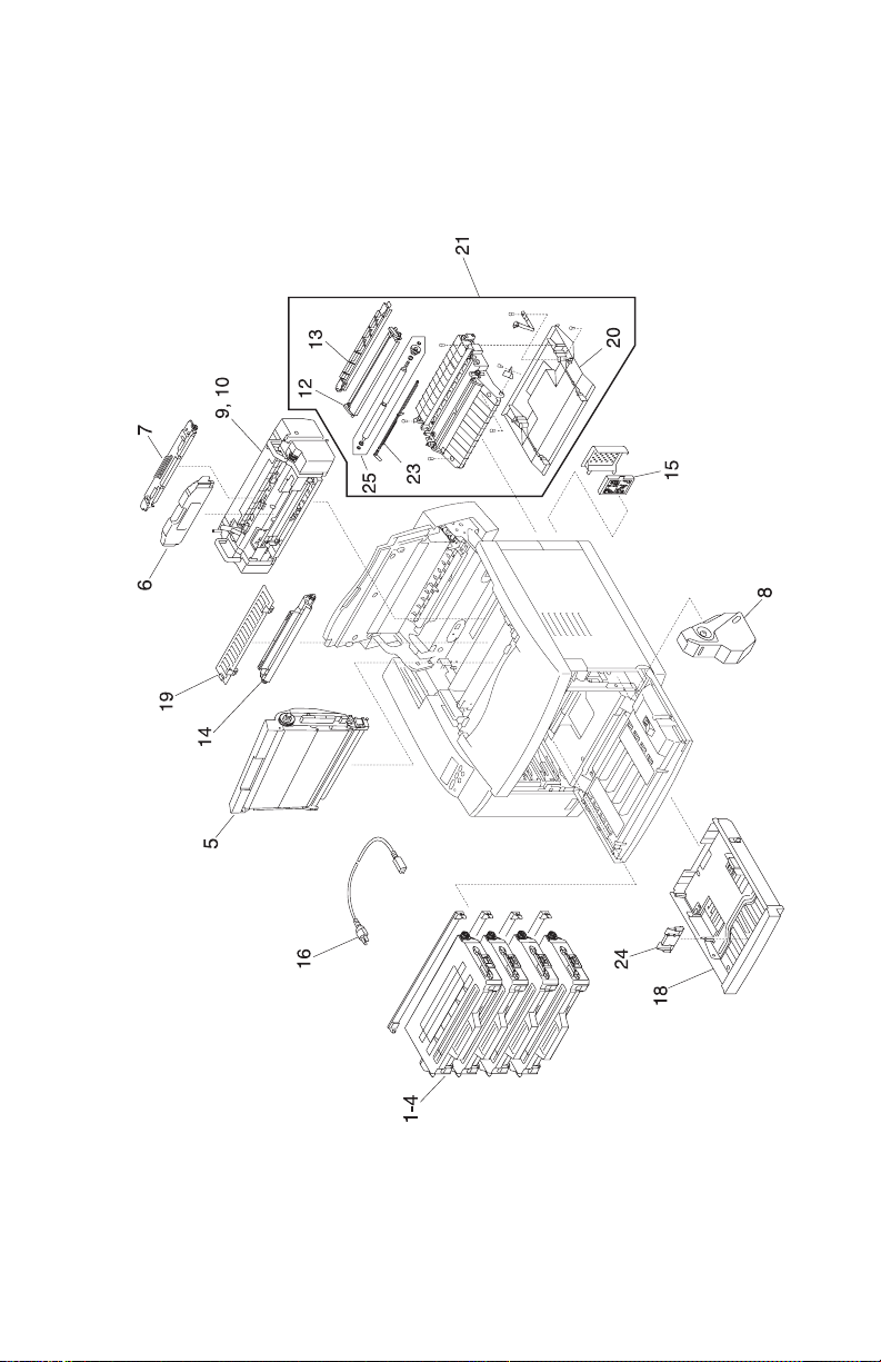
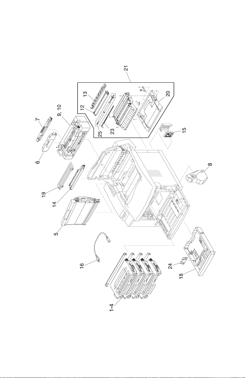
21 12G7013 1
23 12G7014 1
24 12G7159 1
25 12G7160 1
12G7341 1
12G7340 1
Transfer Unit (includes 12, 13, 20, 23, 25)
PT1 Sensor Lever
Paper Cassette Paper Stop
Registration Roller Assembly
Parts Packet, Screws
Parts Packet, Cable Clamps, Retainers,
Miscellaneous
Note: Reference the foldout wiring diagram, in the back of this
manual, for cable replacement detailed information. Then go to
Assembly 6 for parts ordering information.
Parts Catalog 7-5
Page 7
Assembly 2:
Parts Catalog 7-6
Page 8

5024-001
Assembly 2:
Ref Part Number Units Description
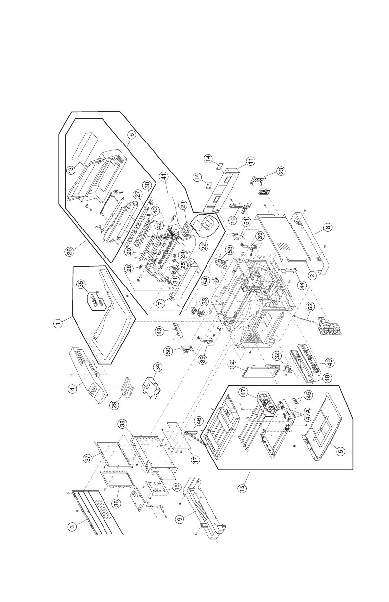
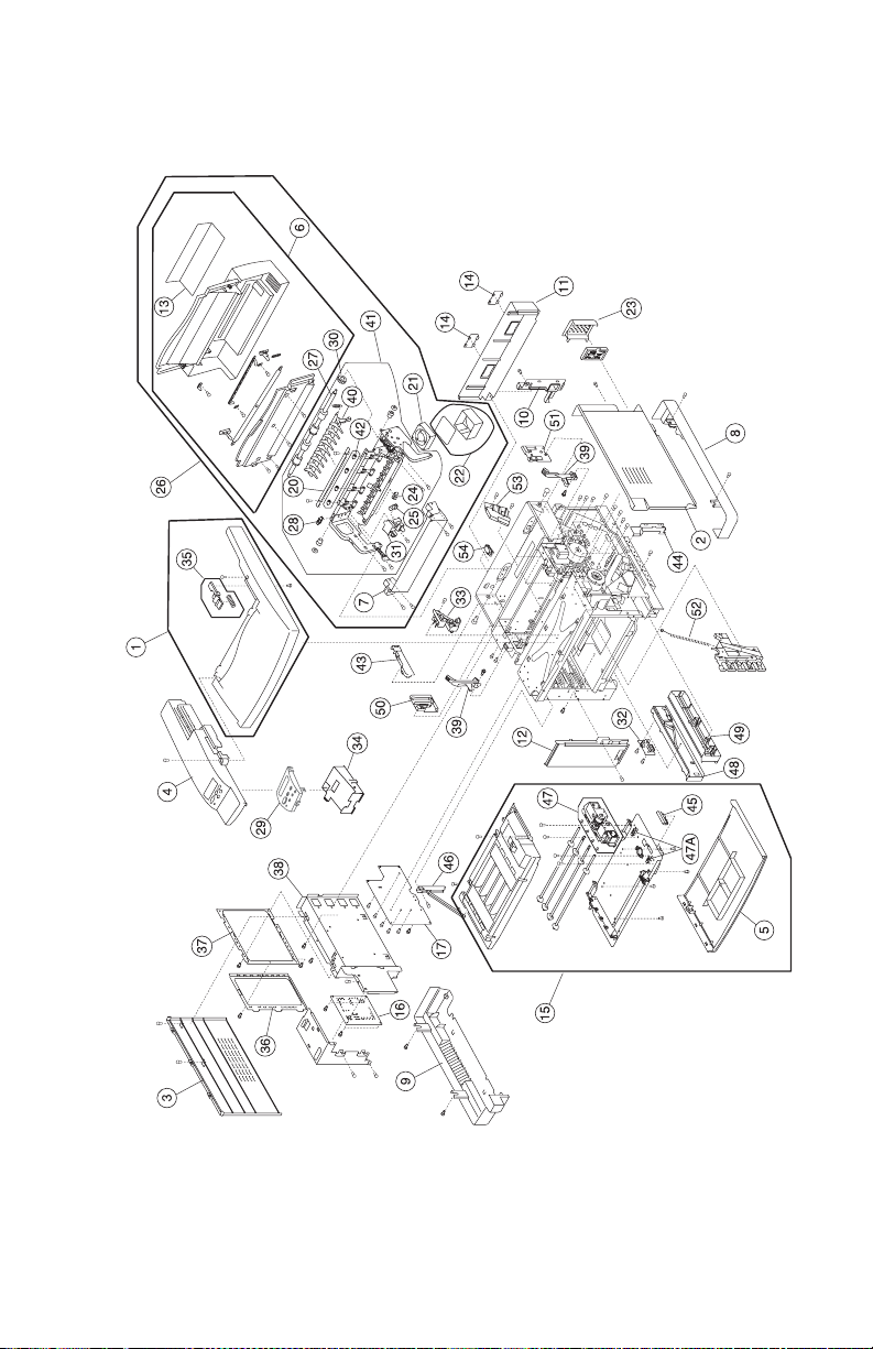
2 - 1 12G7015 1
2 12G7016 1
Top Cover Assembly (includes 35)
Side Cover (R)
3 12G7017 1
4 12G7018 1
5 12G7019 1
6 12G7020 1
7 12G7021 1
8 12G7022 1
9 12G7023 1
10 12G7024 1
11 12G7025 1
12 12G7026 1
13 12G7027 1
14 12G7028 2
15 12G7029 1
16 12G7030 1
17 12G7031 1
20 12G7032 1
Side Cover (L)
Upper Side Cover (L)
Front Cover
Paper Exit Unit Cover (includes 13)
Paper Exit Front Cover
Base Cover (R)
Base Cover (L)
Rear Cover
Rear Cover (U)
Side F Cover (L)
Paper Exit Upper Cover
Rear Cover (U) Cap
Front Cover Unit (includes 5, 45, 47)
Main Engine (MCTL P.W.B.) Board
High Voltage Unit
Discharge Brush
21 12G7033 1
22 12G7034 1
23 12G7035 1
24 12G7036 1
25 12G7037 1
26 12G7038 1
Cooling Fan (HFAN)
Paper Exit Filter (with Case)
Ozone Filter Cover
Paper Sensor (PT2)
Paper Sensor (FCL)
Paper Exit Unit (includes 6, 7, 13, 20, 21,
22, 24, 25, 27, 28, 30, 31, 40, 42)
Parts Catalog 7-7
Page 9
Assembly 2 (cont.):
Parts Catalog 7-8
Page 10

5024-001
Assembly 2 (cont.):
Ref Part Number Units Description
2 - 27 12G7039 1
28 12G7037 1
Paper Exit Roller
Paper sensor (PFUL)
29 12G7360 1
30 12G7041 1
31 12G7042 1
32 12G7043 1
33 12G7044 1
34 12G7161 1
35 12G7162 1
36 12G7163 1
37 12G7164 1
38 12G7165 1
39 12G7166 1
40 12G7167 1
41 12G7168 1
42 12G7169 1
43 12G7170 1
44 12G7171 1
Operator Panel Assembly
Paper Exit Gear Z19
FCS Cover Assembly
Paper Size Sensor
BC Terminal 2
Control Panel Base
Paper Exit Button
Shield Cover B
Shield Cover A
Shield Case Assembly
BC Lock Lever (set)
Paper Exit Switch Guide
Paper Exit Frame Assembly
(includes 7,10,24,25,27,28,30,31,40,42)
Paper Exit Idle Roller Set
Paper Exit Harness Cover
IOD Harness Guide
45 12G7172 1
46 12G7173 1
47 12G7174 1
47A 12G7036 1
48 12G7175 1
49 12G7176 1
Front Cover Latch
Front Cover/Door Arm Assembly
DE Solenoid Assembly (also order 47A)
Cam Sensor, DE Solenoid GPH1, GPH2
Front Paper Cassette Guide (L)
Front Paper Cassette Guide (R)
Parts Catalog 7-9
Page 11

Assembly 2 (cont.):
Parts Catalog 7-10
Page 12

5024-001
Assembly 2 (cont.):
Ref Part Number Units Description
2 - 50 12G7177 1
51 12G7178 1
DC Guide L
DC Guide (R)
52 12G7179 1
53 12G7180 1
54 12G7070 1
12G7341 1
12G7340 1
Waste Toner U Spring
TR Terminal Base Assembly
Interlock Switch
Parts Packet, Screws
Parts Packet, Cable Clamps, Retainers,
Miscellaneous
Note: Reference the foldout wiring diagram, in the back of this
manual, for cable replacement detailed information. Then go to
Assembly 6 for parts ordering information.
Parts Catalog 7-11
Page 13

Assembly 3:
Parts Catalog 7-12
Page 14

5024-001
Assembly 3:
Ref Part Number Units Description
3 - 1 12G7045 1
2 12G7046 1
Paper Feeding Clutch (PCLU)
Registration Clutch (RECL)
3 12G7047 1
4 12G7048 4
5 12G7049 1
6 12G7049 1
7 12G7051 1
8 12G7052 1
9 12G7053 1
10 12G7054 1
11 12G7055 1
12 12G7056 1
13 12G7057 1
14 12G7058 1
15 12G7059 1
16 12G7060 1
17 12G7061 1
18 12G7062 1
Fuser Clutch (FUCL)
Developer Clutch
Transfer Cam Clutch (TRCM)
Cleaner Cam Clutch (FBCM)
Cleaner Clutch (FBCL)
Main Motor (MM)
BD Gear Assembly
Main Gear Unit (includes 2, 3, 5, 6, 7)
Developer Motor (DM)
Developer Drive Unit (includes 4)
Developer Drive Gear (Set)
FP2 Gear Assembly (Front Developer
Solenoid Drive)
Waste Toner Feeder (Lower)
Cooling Fan (OZFAN)
Toner Sensor (TPD, TTR)
Toner Key Sensor (TNK)
19 12G7063 1
20 12G7064 1
21 12G7065 1
22 12G7037 5
23 12G7067 1
24 12G7068 1
Waste Toner Holder Assembly
IOD1 P.W.B.
Transfer Drum
Paper Sensor (Drum Encoder) (HPSEN)
Power Supply Unit (U.S.) 110 V(LVPS)
Power Supply Unit (WT) 220 V (LVPS)
Parts Catalog 7-13
Page 15

Assembly 3 (cont.):
Parts Catalog 7-14
Page 16

5024-001
Assembly 3 (cont.):
Ref Part Number Units Description
3 - 25 12G7069 1
26 12G7070 1
Fuser Connector
Interlock Switch, Front Door
27 12G7073 1
28 12G7074 1
29 12G7075 1
30 12G7076 1
31 12G7077 2
32 12G7078 1
33 12G7079 1
34 12G7079 1
35 12G7081 2
36 12G7082 1
38 12G7083 1
39 12G7084 1
53 12G7181 1
54 12G7182 1
55 12G7183 1
56 12G7184 1
IOD2 P.W.B.
Cooling Fan (CTFAN)
Waste Toner Feeder Unit (Upper)
Erase Lamp
Erase Holder (2 pieces)
Oil Sensor
Belt Sensor (PBS)
Drum Jam Sensor (DPJ)
Paper Guide D (2 pieces)
Optical Unit (Printhead)
SW Button
Cover (FR)
SW Base Front
Inner Cover C
Oil Sensor Cover
Shield Upper
57 12G7185 1
12G7341 1
12G7340 1
PS Fan Assembly (CTFAN) (includes 26,
28)
Parts Packet, Screws
Parts Packet, Cable Clamps, Retainers,
Miscellaneous
Note: Reference the foldout wiring diagram, in the back of this
manual, for cable replacement detailed information. Then go to
Assembly 6 for parts ordering information.
Parts Catalog 7-15
Page 17

Assembly 4:
Parts Catalog 7-16
Page 18

5024-001
Assembly 4:
Ref
4 - 1 12G7098 1
2 12G7099 1
3 12G7100 1
4 12G7037 1
5 12G7037 1
6 12G7103 1
7 12G7104 1
8 12G7186 1
9 12G7187 1
10 12G7188 1
Part
Number
12G7341 1
12G7340 1
Units Description
Paper Feed Roller
Separator Pad
OHP Sensor
Paper Sensor (PEU)
Paper Sensor (PT1)
Paper Guide (UL) Assembly
Paper Guide (UR)
Transfer Unit Rear Band
Transfer Unit Hinge Support Bracket
Paper Guide L
Parts Packet, Screws
Parts Packet, Cable Clamps, Retainers,
Miscellaneous
Note: Reference the foldout wiring diagram, in the back of this
manual, for cable replacement detailed information. Then go to
Assembly 6 for parts ordering information.
Parts Catalog 7-17
Page 19

5024-001
Assembly 5: Controller RIP Card
7-18 Service Manual
Page 20

5024-001
Assembly 5: Controller RIP Card
Ref
5 - 1 12G7227 1
1 12G7226 1
2 12G7228 1
3 99A1752 1
3 99A1755 1
4 12G7229 1
5 12G7231 1
6 99A0459 1
7 11G0962 1
8 12G7230 1
Part
Number
Units Description
Controller RIP Card
Controller RIP Card Network
SIMM Code
4MB SDRAM DIMM
32MB SDRAM DIMM
Riser Card Assembly
Hard Disk Mounting Bracket
Hard Disk
Hard Disk Cable
Bracket, Controller RIP Card
Note: The standard and network models have listed memory. See
Assembly 7 for part number information.
Parts Catalog 7-19
Page 21

5024-001
Assembly 6: Printer Cable Harness Sets
7-20 Service Manual
Page 22

5024-001
Assembly 6: Printer Cable Harness Sets
Ref
6 - 1 12G7342 1
2 12G7343 1
3 12G7344 1
4 12G7345 1
5 12G7346 1
6 12G7347 1
7 12G7348 1
8 12G7349 1
9 12G7350 1
10 12G7351 1
11 12G7352 1
12 12G7353 1
13 12G7354 1
Part
Number
Units Description
Harness WH (A) Wiring Diagram #1
Harness WH (B) Wiring Diagram #2
Harness WH (C) Wiring Diagram #3
Harness WH (D) Wiring Diagram #4
Harness WH (I1/SEN) Wiring Diagram #5
Harness WH (LPC) Wiring Diagram #6
Harness WH (SIZE) Wiring Diagram #7
Harness WH (I1/TO) Wiring Diagram #8
Harness WH (PEX) Wiring Diagram #9
Harness WH (LXPN) Wiring Diagram #10
Harness WH (I2/FD) Wiring Diagram #11
Harness WH (DUAL) Wiring Diagram #12
Harness WH (MC/I1) Wiring Diagram #13
Note: Reference the foldout wiring diagram, in the back of this
manual, for cable replacement detailed information.
Parts Catalog 7-21
Page 23

5024-001
Assembly 7: Miscellaneous
(No illustration)
7-22 Service Manual
Page 24

5024-001
Assembly 7: Miscellaneous
Ref Part Number Units Description
NS 12G1704 1
NS 13A0297 1
NS 13A0296 1
NS 99A0459 1
NS 99A0545 1
NS 12G1696 1
NS 12G1697 1
NS 99A1830 1
NS 99A1752 1
NS 99A1753 1
NS 99A1754 1
NS 99A1755 1
NS 99A1756 1
NS 99A1773 1
NS 99A1757 1
NS 99A1758 1
NS 99A1759 1
NS 99A1774 1
NS 99A0560 1
NS 99A0923 1
NS 99A0467 1
NS
NS 7366394 1
NS 7366417 1
NS 7366413 1
NS 7366409 1
Card Assembly, SIMM IPDS/SCS/TNE
Cable, Coax
Cable, Twinax
Hard Disk, 2.1GB
Adapter, Serial
MarkNet N2000t 4/16 Token Ring
MarkNet N2002e 10Base2/10BaseT
MarkNet N2001e 10/100 Ethernet
4MB SDRAM DIMM
8MB SDRAM DIMM
16MB SDRAM DIMM
32MB SDRAM DIMM
64MB SDRAM DIMM
128MB SDRAM DIMM
2MB Flash DIMM
4MB Flash DIMM
8MB Flash DIMM
16MB Flash DIMM
Tri-Port Adapter (Serial/LocalTalk and Infrared)
Board, USB/Parallel Port
Board, Parallel Port Adapter
Relocation Packaging
- Base Printer
- Lower Feed Unit
- Duplex Unit
- Base Printer / Duplex bundle
Parts Catalog 7-23
Page 25

5024-001
Assembly 8: Lower Feed Unit
7-24 Service Manual
Page 26

5024-001
Assembly 8: Lower Feed Unit
Ref
8 - 1 12G7037 1
2 12G7043 1
3 12G7045 1
4 12G7098 1
5 12G7099 1
6 12G7121 1
7 12G7122 1
8 12G7123 1
9 12G7124 1
10 12G7144 1
11 12G7224 1
12 12G7145 1
13 12G7146 1
14 12G7147 1
15 12G7148 1
16 12G7149 1
Part
Number
Units Description
Paper Sensor (PEL)
Paper Size Sensor (PSL)
Paper Feed Clutch (PKCL)
Paper Feed Roller
Separator Pad (2)
LF Side Cover R
LF Side Cover L
LF Clutch Drive, Transport Roller (DPKCL)
LF Rear Cover Assembly (includes Transport
Roll)
Drive Gear Assembly
LF Paper Feed Cassette
LF Base Cover (R) Assembly
LF Base Cover (L)
LF Top Cover (R)
LF Top Cover (L)
LF Front Top Cover
17 12G7150 1
18 12G7151 1
-19 12G7152 1
20 12G7153 1
21 12G7154 1
22 12G7155 1
23 12G7156 1
12G7135 1
LF Cassette Guide (R)
LF Cassette Guide (L)
LF Paper Guide (UR)
LF Paper Guide (UL)
LF Rear Top Cover
GND Contacts
Cable Harness
LFU / Duplex Parts Packet, Screws
Parts Catalog 7-25
Page 27

5024-001
Assembly 8 (cont.): Lower Feed Unit (cont.)
7-26 Service Manual
Page 28

5024-001
Assembly 8 (cont.): Lower Feed Unit (cont.)
Ref
Part
Number
12G7135 1
12G7136 1
12G7137 1
12G7139 1
Units Description
LFU / Duplex Parts Packet, Screws
LFU / Duplex Parts Packet, Retainers
LFU / Duplex Parts Packet, Cable Tie /
Guides
LFU / Duplex Parts Packet, Springs
Note: Reference the foldout wiring diagram, in the back of this
manual, for cable replacement detailed information. Then go to the
assembly for parts ordering information.
Parts Catalog 7-27
Page 29

5024-001
Assembly 9: Duplex Unit
7-28 Service Manual
Page 30

5024-001
Assembly 9: Duplex Unit
Ref
9 - 1 12G7105 1
2 12G7106 1
3 12G7107 1
4 12G7108 1
5 12G7109 1
6 12G7110 1
7 12G7111 1
8 12G7112 1
9 12G7113 1
10 12G7114 1
11 12G7115 1
12 12G7116 1
13 12G7138 1
14 12G7117 1
16 12G7140 1
17 12G7141 1
Part
Number
Units Description
Cover Top (C) Assembly
Cover Top (L)
Cover Top (R)
Cover Top (B) Assembly
Cover Low (L)
Cover Low (R)
Cover Low (B) Assembly
Paper Guide Bottom Assembly (includes 19,
25, 28)
Paper Guide RVS Assembly (includes 20,
29)
Paper Guide Inner
Motor 1(DPM1)
Motor 2 (DPM2)
4 Cable Bill of Material (Door, P.W.B.P.W.B.,I/F, Solenoid, PT4 P.W.B., Fan)
Relay P.W.B.
Solenoid (U) Assembly
Solenoid (L) Assembly
18 12G7070 4
19 12G7143 1
20 12G7125 1
21 12G7118 1
22 12G7119 1
Interlock Switch (DSW1 - DSW4)
D Sensor (PT4)
D Sensor (PT5)
Paper Guide U Assembly (includes printer
reference 26)
DUP P.W.B.
Parts Catalog 7-29
Page 31

5024-001
Assembly 9 (cont.): Duplex Unit (cont.)
7-30 Service Manual
Page 32

5024-001
Assembly 9: Duplex Unit
Ref
9 - 23 12G7120 1
24 12G7139 1
25 12G7126 1
26 12G7127 1
27 12G7128 1
28 12G7129 1
29 12G7130 1
30 12G7131 2
31 12G7132 1
32 12G7133 1
33 12G7134 2
35 12G7136 1
36 12G7138 1
Part
Number
12G7135 1
12G7136 1
12G7137 1
12G7139 1
Units Description
Cover Bottom
Spring (contains 2 springs)
D Roller (contains 20 rollers)
3 Belts
Lid-WH Bottom
D Sensor Bottom Bill of Material
D Sensor Middle Bill of Material
D Gear Cover
Gate Bottom
Band-Spring Set
3 Gears-Belt Set
LFU / Duplex Screw Parts Pack
Fan Motor (DFAN)
LFU / Duplex Parts Packet, Screws
LFU / Duplex Parts Packet, Retainers
LFU / Duplex Parts Packet, Cable Tie /
Guides
LFU / Duplex Parts Packet, Springs
Note: Reference the foldout wiring diagram, in the back of this
manual, for cable replacement detailed information. Then go to the
assembly for parts ordering information.
Parts Catalog 7-31
Page 33

5024-001
7-32 Service Manual
 Loading...