

Page 1

Lexmark OptraTM C710
• Table of Contents
• Start Diagnostics
• Safety and Notices
• Trademarks
5016-001
•Index
Lexmark and Lexmark with diamond
design are trademarks of Lexmark
International, Inc., registered in the
United States and/or other countries.
Page 2

5016-001
Edition: May 2001
The following paragraph does not apply to any country where suc h provisions are
inconsiste nt with local law: LEXMARK INTERNATIONAL, INC. PROV IDES THIS
PUBLICATION “AS IS” WITHOUT WARRANTY OF ANY KIND, EITHER EXPRE SS OR
IMPLIED , INCLUDING, BUT NOT LIMITED TO, THE IMPLIED WARRANTIES OF
MERCHANTABILITY OR FITNESS FOR A PARTICULAR PURPOSE. Some states do
not allow disclaimer of express or implied warranties in certain transactions; therefore,
this statement may not apply to you.
This publication could include technical inaccuracies or typographical errors. Changes
are periodically made to the information herein; these changes will be incorporated in
later editions. Improvements or changes in the products or the programs described may
be made at any time.
Comments may be addressed to Lexmark International, Inc., Department D22A/032-2,
740 West New Circle Road, Lexington, Kentucky 40550, U.S.A or e-mail at
ServiceInfoAndTraining@Lexmark.com. Lexmark may use or distribute any of the
information you supply in any way it believes appropriate without incurring any obligation
to you. You can purchase additional copies of publications related to this product by
calling 1-800-553-9727. In other countries, contact your point of purchase.
Lexmark and Optra are trademarks of Lexmark International, Inc., registered in the United
States and/or other countries.
Color Jetprinter is a trademark of Lexmark International, Inc.
Other trademarks are the property of their respective owners.
© Copyright Lexmark International, Inc. 2000, 2001.
All rights reserved.
UNITED STA TES GOVERNMENT RESTRICTED RIGHTS
This software and documentation are provided with RESTRICTED RIGHTS. Use,
duplication or disclosure by the Government is subject to restrictions as set forth in
subparagraph (c)(1)(ii) of the Rights in Technical Data and Computer Software clause at
DF ARS 252.227-7013 and in applicable FAR provisions: Lexmark International, Inc.,
Lexington, KY 40550.
P/N: 12G6111
Page 3

5016-001
Table of Contents
Notices and Safety Information . . . . . . . . . . . . . . . . . . . . . . . . . . . . ix
Laser Notices . . . . . . . . . . . . . . . . . . . . . . . . . . . . . . . . . . . . . . . . . . . ix
General Information . . . . . . . . . . . . . . . . . . . . . . . . . . . . . . . . . . . . 1-1
Models . . . . . . . . . . . . . . . . . . . . . . . . . . . . . . . . . . . . . . . . . . . . . . . 1-2
Standard Features . . . . . . . . . . . . . . . . . . . . . . . . . . . . . . . . . . . . . . 1-2
Tools Required For Service . . . . . . . . . . . . . . . . . . . . . . . . . . . . . 1-6
Options . . . . . . . . . . . . . . . . . . . . . . . . . . . . . . . . . . . . . . . . . . . . . . . 1-7
Operational Theory . . . . . . . . . . . . . . . . . . . . . . . . . . . . . . . . . . . . . . 1-8
Interlock Mechanism . . . . . . . . . . . . . . . . . . . . . . . . . . . . . . . . . . 1-8
Sheet Bypass Paper Feed Unit . . . . . . . . . . . . . . . . . . . . . . . . . . 1-9
Paper Feed Unit. . . . . . . . . . . . . . . . . . . . . . . . . . . . . . . . . . . . . 1-11
Second Paper Feed Unit (Optional Paper Trays) . . . . . . . . . . . 1-13
Drive Block. . . . . . . . . . . . . . . . . . . . . . . . . . . . . . . . . . . . . . . . . 1-17
Contact Cam . . . . . . . . . . . . . . . . . . . . . . . . . . . . . . . . . . . . . . . 1-18
Coupling Unit . . . . . . . . . . . . . . . . . . . . . . . . . . . . . . . . . . . . . . . 1-19
Carriage Unit . . . . . . . . . . . . . . . . . . . . . . . . . . . . . . . . . . . . . . . 1-21
Toner Cartridge Unit. . . . . . . . . . . . . . . . . . . . . . . . . . . . . . . . . . 1-22
Intermediate Transfer Unit . . . . . . . . . . . . . . . . . . . . . . . . . . . . . 1-24
Fuser/Paper Exit Unit. . . . . . . . . . . . . . . . . . . . . . . . . . . . . . . . . 1-27
Detecting New Cleaning Unit . . . . . . . . . . . . . . . . . . . . . . . . . . . 1-28
Duplex Unit (Optio n). . . . . . . . . . . . . . . . . . . . . . . . . . . . . . . . . . 1-29
Diagnostic Information . . . . . . . . . . . . . . . . . . . . . . . . . . . . . . . . . 2-1
Start . . . . . . . . . . . . . . . . . . . . . . . . . . . . . . . . . . . . . . . . . . . . . . . . . 2-1
Service Error Codes . . . . . . . . . . . . . . . . . . . . . . . . . . . . . . . . . . . . . 2-2
User Status Messages . . . . . . . . . . . . . . . . . . . . . . . . . . . . . . . . . . . 2-7
User Attendance Messages . . . . . . . . . . . . . . . . . . . . . . . . . . . . . . 2-13
Symptom Tables . . . . . . . . . . . . . . . . . . . . . . . . . . . . . . . . . . . . . . 2-28
Base Printer Symptom Table. . . . . . . . . . . . . . . . . . . . . . . . . . . 2-28
Covers Interlock Symptom Table . . . . . . . . . . . . . . . . . . . . . . 2-29
Duplex Unit Symptom Table . . . . . . . . . . . . . . . . . . . . . . . . . . . 2-29
Operator Panel Symptom Table . . . . . . . . . . . . . . . . . . . . . . . 2-30
Paper Feed Symptom Table . . . . . . . . . . . . . . . . . . . . . . . . . . . 2-30
Paper Tray Options Symptom Table . . . . . . . . . . . . . . . . . . . . . 2-31
Power Symptom Table . . . . . . . . . . . . . . . . . . . . . . . . . . . . . . . 2-31
Print Quality Symptom Table . . . . . . . . . . . . . . . . . . . . . . . . . . . 2-32
Service Checks . . . . . . . . . . . . . . . . . . . . . . . . . . . . . . . . . . . . . . . 2-34
Base Printer Service Checks . . . . . . . . . . . . . . . . . . . . . . . . . . . . . 2-35
Bypass Tray (Multipurpose Tray) Service Check. . . . . . . . . . . . 2-35
iii
Page 4

5016-001
Carriage Unit Service Check. . . . . . . . . . . . . . . . . . . . . . . . . . . .2-39
Coupling Unit Service Check. . . . . . . . . . . . . . . . . . . . . . . . . . . .2-42
Cover Interlock Service Ch eck . . . . . . . . . . . . . . . . . . . . . . . . . .2-45
Developer/Paper Feed Motor Service Check . . . . . . . . . . . . . . .2-48
Erase Lamp Service Check. . . . . . . . . . . . . . . . . . . . . . . . . . . . .2-50
Fuser Cold Service Check. . . . . . . . . . . . . . . . . . . . . . . . . . . . . .2-51
Fuser Drive and Contact Cam System Service Check . . . . . . . .2-53
Fuser Hot Service Check . . . . . . . . . . . . . . . . . . . . . . . . . . . . . .2-57
High Voltage Leakage Detect Service Check . . . . . . . . . . . . . . .2-58
ITM Drive Service Check. . . . . . . . . . . . . . . . . . . . . . . . . . . . . . .2-60
Main Fan Service Check . . . . . . . . . . . . . . . . . . . . . . . . . . . . . . .2-62
New Toner Cartridge Detection Service Check. . . . . . . . . . . . . .2-63
Operator Panel Service Check . . . . . . . . . . . . . . . . . . . . . . . . . .2-64
Operator Panel Buttons Service Check. . . . . . . . . . . . . . . . . . . .2-65
OPC Drive Service Check. . . . . . . . . . . . . . . . . . . . . . . . . . . . . .2-66
Paper Exit Sensor Service Check . . . . . . . . . . . . . . . . . . . . . . . .2-67
Paper Feed Service Check . . . . . . . . . . . . . . . . . . . . . . . . . . . . .2-68
Parallel Port Service Check. . . . . . . . . . . . . . . . . . . . . . . . . . . . .2-71
Power Service Check . . . . . . . . . . . . . . . . . . . . . . . . . . . . . . . . .2-72
Printhead Service Check. . . . . . . . . . . . . . . . . . . . . . . . . . . . . . .2-77
Print Quality Service Checks . . . . . . . . . . . . . . . . . . . . . . . . . . . . . .2-79
Print Quality Initial Service Check. . . . . . . . . . . . . . . . . . . . . . . .2-79
All Black or Color Page Service Check . . . . . . . . . . . . . . . . . . . .2-80
All Blank Page Service Check. . . . . . . . . . . . . . . . . . . . . . . . . . .2-81
Background Service Check. . . . . . . . . . . . . . . . . . . . . . . . . . . . .2-82
Black, Color Lines or Bands Service Check . . . . . . . . . . . . . . . .2-83
Black or Color Spots Service Check . . . . . . . . . . . . . . . . . . . . . .2-84
Developer Drive System Service Check . . . . . . . . . . . . . . . . . . .2-84
Evenly Spaced Horizontal Lines/Marks Service Check. . . . . . . .2-85
Foggy Background Service Check . . . . . . . . . . . . . . . . . . . . . . .2-86
Low Image Density Service Check . . . . . . . . . . . . . . . . . . . . . . .2-87
Offset Print Service Check . . . . . . . . . . . . . . . . . . . . . . . . . . . . .2-88
Poor Color Reproduction Service Check. . . . . . . . . . . . . . . . . . .2-89
Random Marks Service Check . . . . . . . . . . . . . . . . . . . . . . . . . .2-90
Residual Image Service Check . . . . . . . . . . . . . . . . . . . . . . . . . .2-90
Skew Service Check . . . . . . . . . . . . . . . . . . . . . . . . . . . . . . . . . .2-91
Toner on Backside of Page Service Check. . . . . . . . . . . . . . . . .2-91
Uneven Print Density Service Check . . . . . . . . . . . . . . . . . . . . .2-92
White Lines or Bands Service Check . . . . . . . . . . . . . . . . . . . . .2-92
White Spots Service Check . . . . . . . . . . . . . . . . . . . . . . . . . . . .2-94
White/Black Lines Service Check . . . . . . . . . . . . . . . . . . . . . . . .2-95
Serial Port Service Check . . . . . . . . . . . . . . . . . . . . . . . . . . . . . .2-96
Toner Level Detect Service Check . . . . . . . . . . . . . . . . . . . . . . .2-96
iv Service Manual
Page 5

5016-001
Toner Low/Empty Sensor Service Check . . . . . . . . . . . . . . . . . 2-97
Transfer Roll Service Check . . . . . . . . . . . . . . . . . . . . . . . . . . . 2-98
Tray 1 (Integrated Tray) Service Check. . . . . . . . . . . . . . . . . . . 2-99
Options Service Checks . . . . . . . . . . . . . . . . . . . . . . . . . . . . . . . . 2-106
Flash Memory Option(s) Service Check . . . . . . . . . . . . . . . . . 2-106
DRAM Memory Option(s) Service Check. . . . . . . . . . . . . . . . . 2-106
Hard Disk Option Service Check . . . . . . . . . . . . . . . . . . . . . . . 2-107
Network Card Option Service Check . . . . . . . . . . . . . . . . . . . . 2-108
250/250 Dual Paper Tray Service Check. . . . . . . . . . . . . . . . . 2-108
250/250 Paper Tray Symptom Table . . . . . . . . . . . . . . . . . . . . 2-109
Duplex Unit Option Service Check. . . . . . . . . . . . . . . . . . . . . . 2-120
Diagnostic Aids . . . . . . . . . . . . . . . . . . . . . . . . . . . . . . . . . . . . . . . 3-1
Print Quality Test Pages . . . . . . . . . . . . . . . . . . . . . . . . . . . . . . . 3-1
Paper Jam Sequence. . . . . . . . . . . . . . . . . . . . . . . . . . . . . . . . . . 3-1
Disabling Download Emulati ons. . . . . . . . . . . . . . . . . . . . . . . . . . 3-3
Diagnostics Menu Structur e. . . . . . . . . . . . . . . . . . . . . . . . . . . . . 3-3
Diagnostic Mode . . . . . . . . . . . . . . . . . . . . . . . . . . . . . . . . . . . . . . . . 3-4
Print Registration . . . . . . . . . . . . . . . . . . . . . . . . . . . . . . . . . . . . . . . 3-6
Print Tests . . . . . . . . . . . . . . . . . . . . . . . . . . . . . . . . . . . . . . . . . . . . 3-8
Print Quality Test Pages . . . . . . . . . . . . . . . . . . . . . . . . . . . . . . . 3-9
Hardware Tests . . . . . . . . . . . . . . . . . . . . . . . . . . . . . . . . . . . . . . . 3-10
LCD Test . . . . . . . . . . . . . . . . . . . . . . . . . . . . . . . . . . . . . . . . . . 3-10
Button Test. . . . . . . . . . . . . . . . . . . . . . . . . . . . . . . . . . . . . . . . . 3-10
Parallel Wrap Test . . . . . . . . . . . . . . . . . . . . . . . . . . . . . . . . . . . 3-11
ROM Memory Test. . . . . . . . . . . . . . . . . . . . . . . . . . . . . . . . . . . 3-12
SDRAM Memory Test . . . . . . . . . . . . . . . . . . . . . . . . . . . . . . . . 3-13
Serial Wrap Test . . . . . . . . . . . . . . . . . . . . . . . . . . . . . . . . . . . . 3-14
Duplex Tests . . . . . . . . . . . . . . . . . . . . . . . . . . . . . . . . . . . . . . . . . 3-15
Quick Test . . . . . . . . . . . . . . . . . . . . . . . . . . . . . . . . . . . . . . . . . 3-15
Duplex Feed 1 . . . . . . . . . . . . . . . . . . . . . . . . . . . . . . . . . . . . . . 3-15
Duplex Feed 2 . . . . . . . . . . . . . . . . . . . . . . . . . . . . . . . . . . . . . . 3-15
Device Tests . . . . . . . . . . . . . . . . . . . . . . . . . . . . . . . . . . . . . . . . . . 3-16
Quick Disk Test . . . . . . . . . . . . . . . . . . . . . . . . . . . . . . . . . . . . . 3-16
Disk Test/Clean . . . . . . . . . . . . . . . . . . . . . . . . . . . . . . . . . . . . . 3-17
Flash Test . . . . . . . . . . . . . . . . . . . . . . . . . . . . . . . . . . . . . . . . . 3-18
Printer Setup . . . . . . . . . . . . . . . . . . . . . . . . . . . . . . . . . . . . . . . . . 3-19
Setting the Page Count . . . . . . . . . . . . . . . . . . . . . . . . . . . . . . . 3-19
Viewing the Permanent Page Count . . . . . . . . . . . . . . . . . . . . . 3-19
Serial Number . . . . . . . . . . . . . . . . . . . . . . . . . . . . . . . . . . . . . . 3-19
Setting Configuration ID. . . . . . . . . . . . . . . . . . . . . . . . . . . . . . . 3-20
Laser Power. . . . . . . . . . . . . . . . . . . . . . . . . . . . . . . . . . . . . . . . 3-21
Parallel Strobe Adjustment. . . . . . . . . . . . . . . . . . . . . . . . . . . . . 3-21
v
Page 6

5016-001
Error Log . . . . . . . . . . . . . . . . . . . . . . . . . . . . . . . . . . . . . . . . . . . . .3-22
Viewing the Error Log . . . . . . . . . . . . . . . . . . . . . . . . . . . . . . . . .3-22
Clearing the Error Log. . . . . . . . . . . . . . . . . . . . . . . . . . . . . . . . .3-22
Restore EP Factory Defaults. . . . . . . . . . . . . . . . . . . . . . . . . . . .3-22
Exiting Diagnostic Mode . . . . . . . . . . . . . . . . . . . . . . . . . . . . . . . . .3-23
Repair Information . . . . . . . . . . . . . . . . . . . . . . . . . . . . . . . . . . . . . .4-1
Handling ESD-Sensi ti ve Par ts . . . . . . . . . . . . . . . . . . . . . . . . . . . . . .4-1
Cover Removals . . . . . . . . . . . . . . . . . . . . . . . . . . . . . . . . . . . . . . . .4-2
Cartridge Cover Removal . . . . . . . . . . . . . . . . . . . . . . . . . . . . . . .4-3
Front Cover Removal . . . . . . . . . . . . . . . . . . . . . . . . . . . . . . . . . .4-3
Fuser Cover Removal . . . . . . . . . . . . . . . . . . . . . . . . . . . . . . . . . .4-3
Left Side Cover Removal . . . . . . . . . . . . . . . . . . . . . . . . . . . . . . .4-3
Operator Panel Cover Removal . . . . . . . . . . . . . . . . . . . . . . . . . .4-3
Rear Cover Removal. . . . . . . . . . . . . . . . . . . . . . . . . . . . . . . . . . .4-3
Right Side Cover Removal . . . . . . . . . . . . . . . . . . . . . . . . . . . . . .4-4
Top Cover Removal . . . . . . . . . . . . . . . . . . . . . . . . . . . . . . . . . . .4-4
Top (Small) Cover Removal . . . . . . . . . . . . . . . . . . . . . . . . . . . . .4-4
Right Side Removals . . . . . . . . . . . . . . . . . . . . . . . . . . . . . . . . . . . . .4-5
Carriage Drive Motor Removal . . . . . . . . . . . . . . . . . . . . . . . . . . .4-6
Coupling Drive Motor Removal . . . . . . . . . . . . . . . . . . . . . . . . . . .4-7
Developer Drive Motor Assembly Removal. . . . . . . . . . . . . . . . . .4-7
Fuser Drive Motor Removal . . . . . . . . . . . . . . . . . . . . . . . . . . . . .4-8
OPC Drive Motor Removal . . . . . . . . . . . . . . . . . . . . . . . . . . . . . .4-9
Cam Sensor Removal . . . . . . . . . . . . . . . . . . . . . . . . . . . . . . . . . .4-9
LVPS Assembly Removal . . . . . . . . . . . . . . . . . . . . . . . . . . . . .4-10
Main Fan Removal . . . . . . . . . . . . . . . . . . . . . . . . . . . . . . . . . . .4-12
Main Fan Mounting Bracket Removal. . . . . . . . . . . . . . . . . . . . .4-12
Motor Mounting Stay C Assembly Removal . . . . . . . . . . . . . . . .4-13
OPC Coupling Drive Block Assembly Removal . . . . . . . . . . . . .4-14
Solenoid Removal . . . . . . . . . . . . . . . . . . . . . . . . . . . . . . . . . . . .4-14
Left Side Removals . . . . . . . . . . . . . . . . . . . . . . . . . . . . . . . . . . . . .4-15
Grid Block 1 Assembly Removal. . . . . . . . . . . . . . . . . . . . . . . . .4-16
Grid Block 2 Assembly Removal. . . . . . . . . . . . . . . . . . . . . . . . .4-17
Cable Cover 3 Removal . . . . . . . . . . . . . . . . . . . . . . . . . . . . . . .4-18
Cover Interlock Switch Removal . . . . . . . . . . . . . . . . . . . . . . . . .4-18
Micro Switch Removal. . . . . . . . . . . . . . . . . . . . . . . . . . . . . . . . .4-18
Electronics Removals . . . . . . . . . . . . . . . . . . . . . . . . . . . . . . . . . . .4-19
Controller Board Assembly Removal . . . . . . . . . . . . . . . . . . . . .4-19
Engine Board Assembly Removal. . . . . . . . . . . . . . . . . . . . . . . .4-19
HVPS Board Assembly Removal . . . . . . . . . . . . . . . . . . . . . . . .4-20
Interconnect Board Assembly Removal . . . . . . . . . . . . . . . . . . .4-21
On/Off Coupling Sensor Board Removal . . . . . . . . . . . . . . . . . .4-21
vi Service Manual
Page 7

5016-001
Paper Sensor Board. . . . . . . . . . . . . . . . . . . . . . . . . . . . . . . . . . 4-21
Resist Sensor Board Removal. . . . . . . . . . . . . . . . . . . . . . . . . . 4-22
Waste Toner Board Assembly Removal . . . . . . . . . . . . . . . . . . 4-22
Fuser Unit . . . . . . . . . . . . . . . . . . . . . . . . . . . . . . . . . . . . . . . . . . . . 4-23
Fuser Unit Removal . . . . . . . . . . . . . . . . . . . . . . . . . . . . . . . . . . 4-23
Fuser Lamp Removal. . . . . . . . . . . . . . . . . . . . . . . . . . . . . . . . . 4-23
Thermistor and Thermostat Removal. . . . . . . . . . . . . . . . . . . . . 4-23
Main Body . . . . . . . . . . . . . . . . . . . . . . . . . . . . . . . . . . . . . . . . . . . 4-24
Paper Feed Block Assembly Removal. . . . . . . . . . . . . . . . . . . . 4-24
Printhead Removal. . . . . . . . . . . . . . . . . . . . . . . . . . . . . . . . . . . 4-24
Print Cartridge Carousel Removal . . . . . . . . . . . . . . . . . . . . . . . 4-25
Carriage Home Position Sensor Removal . . . . . . . . . . . . . . . . . 4-26
Registration Roll Removal . . . . . . . . . . . . . . . . . . . . . . . . . . . . . 4-27
Connector Locations . . . . . . . . . . . . . . . . . . . . . . . . . . . . . . . . . . . 5-1
Engine Board . . . . . . . . . . . . . . . . . . . . . . . . . . . . . . . . . . . . . . . . 5-1
LVPS (Low Voltage Power Supply) . . . . . . . . . . . . . . . . . . . . . . . 5-3
Erase Lamp Board . . . . . . . . . . . . . . . . . . . . . . . . . . . . . . . . . . . . 5-3
TRAY 1 Sensor Board . . . . . . . . . . . . . . . . . . . . . . . . . . . . . . . . . 5-3
TRAY 1 Registration Sensor Board . . . . . . . . . . . . . . . . . . . . . . . 5-4
Waste Toner Sensor Board . . . . . . . . . . . . . . . . . . . . . . . . . . . . . 5-4
Belt Position Sensor Board . . . . . . . . . . . . . . . . . . . . . . . . . . . . . 5-5
Connector Locations for Options . . . . . . . . . . . . . . . . . . . . . . . . . . . 5-6
2nd Paper Option (250/250 Paper Option) . . . . . . . . . . . . . . . . . 5-6
2nd Paper Option (250/250 Paper Option) . . . . . . . . . . . . . . . . . 5-7
LVPS (Internal 2nd Tray Option) . . . . . . . . . . . . . . . . . . . . . . . . . 5-7
Duplex Unit Option . . . . . . . . . . . . . . . . . . . . . . . . . . . . . . . . . . . 5-8
LVPS (Internal Automatic Duplex Option) . . . . . . . . . . . . . . . . . . 5-9
Electrical Components . . . . . . . . . . . . . . . . . . . . . . . . . . . . . . . . . . 5-10
Sensor/Switch Locations . . . . . . . . . . . . . . . . . . . . . . . . . . . . . . 5-10
Printer Circuit Board Locations . . . . . . . . . . . . . . . . . . . . . . . . . 5-13
Fan/Motor Locations . . . . . . . . . . . . . . . . . . . . . . . . . . . . . . . . . 5-13
Solenoid/Clutch Locations . . . . . . . . . . . . . . . . . . . . . . . . . . . . . 5-14
250/250 Paper Tray Option . . . . . . . . . . . . . . . . . . . . . . . . . . . . 5-15
Duplex Option . . . . . . . . . . . . . . . . . . . . . . . . . . . . . . . . . . . . . . 5-15
Cable Connections . . . . . . . . . . . . . . . . . . . . . . . . . . . . . . . . . . . . . 5-16
Preventive Maintenance . . . . . . . . . . . . . . . . . . . . . . . . . . . . . . . . 6-1
Safety Inspection Guide. . . . . . . . . . . . . . . . . . . . . . . . . . . . . . . . 6-1
Service Precautions . . . . . . . . . . . . . . . . . . . . . . . . . . . . . . . . . . 6-1
Cleaning Procedures . . . . . . . . . . . . . . . . . . . . . . . . . . . . . . . . . . 6-1
Lubrication Specific at ion s . . . . . . . . . . . . . . . . . . . . . . . . . . . . . . 6-1
Parts Catalog . . . . . . . . . . . . . . . . . . . . . . . . . . . . . . . . . . . . . . . . . 7-1
vii
Page 8

5016-001
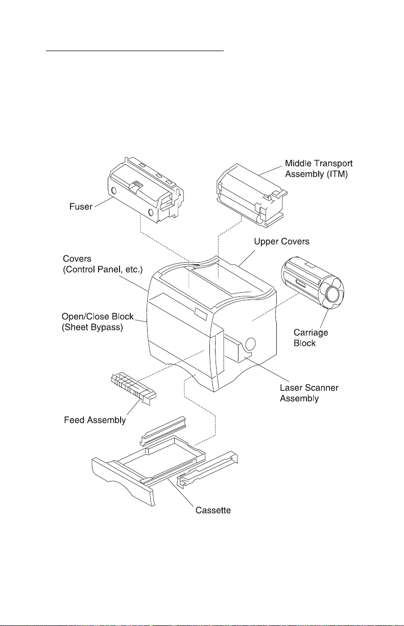
How To Use The Parts Catalog . . . . . . . . . . . . . . . . . . . . . . . . . . . . .7-1
Assembly 1: Fuser . . . . . . . . . . . . . . . . . . . . . . . . . . . . . . . . . . . . . . .7-2
Assembly 2: Fuser . . . . . . . . . . . . . . . . . . . . . . . . . . . . . . . . . . . . . . .7-4
Assembly 3: Transfer . . . . . . . . . . . . . . . . . . . . . . . . . . . . . . . . . . . . .7-8
Assembly 4: Frames. . . . . . . . . . . . . . . . . . . . . . . . . . . . . . . . . . . . .7-10
Assembly 5: Frames Left Side . . . . . . . . . . . . . . . . . . . . . . . . . . . . .7-12
Assembly 6: Frames Right Side . . . . . . . . . . . . . . . . . . . . . . . . . . . .7-16
Assembly 7: Frames Right Side 2 . . . . . . . . . . . . . . . . . . . . . . . . . .7-20
Assembly 8: Frames Right Side 3 . . . . . . . . . . . . . . . . . . . . . . . . . .7-24
Assembly 9: Carriage Block . . . . . . . . . . . . . . . . . . . . . . . . . . . . . . .7-26
Assembly 10: Base Frame . . . . . . . . . . . . . . . . . . . . . . . . . . . . . . . .7-28
Assembly 11: Front Cover Assembly. . . . . . . . . . . . . . . . . . . . . . . .7-30
Assembly 12: Front Cover Assembly 2 . . . . . . . . . . . . . . . . . . . . . .7-34
Assembly 13: Feed Unit . . . . . . . . . . . . . . . . . . . . . . . . . . . . . . . . . .7-38
Assembly 14: Laser Scanner Unit . . . . . . . . . . . . . . . . . . . . . . . . . .7-40
Assembly 15: Cassette. . . . . . . . . . . . . . . . . . . . . . . . . . . . . . . . . . .7-44
Assembly 16: Upper Covers. . . . . . . . . . . . . . . . . . . . . . . . . . . . . . .7-46
Assembly 17: Covers . . . . . . . . . . . . . . . . . . . . . . . . . . . . . . . . . . . .7-50
Assembly 18: Covers / Frame 250 Tray Option . . . . . . . . . . . . . . . .7-52
Assembly 19: Middle Roll Unit 250 Tray Option. . . . . . . . . . . . . . . .7-56
Assembly 20: 250/250 Tray Option Lower Unit . . . . . . . . . . . . . . . .7-58
Assembly 21: Duplex Unit Option 2 . . . . . . . . . . . . . . . . . . . . . . . . .7-60
Assembly 22: Cassette Upper Section. . . . . . . . . . . . . . . . . . . . . . .7-64
Assembly 23: Casse tte Rear Section 1 . . . . . . . . . . . . . . . . . . . . . .7-66
Assembly 24: Casse tte Rear Section 2 . . . . . . . . . . . . . . . . . . . . . .7-68
Assembly 25: Duplex Option Lower Section 1 . . . . . . . . . . . . . . . . .7-70
Assembly 26: Duplex Option Lower Section 2 . . . . . . . . . . . . . . . . .7-74
Assembly 27: Duplex Option Lower Section 3 . . . . . . . . . . . . . . . . .7-76
Assembly 28: Cassette Lower Section 4 . . . . . . . . . . . . . . . . . . . . .7-78
Assembly 29: Duplex Option Lower Section 5 . . . . . . . . . . . . . . . . .7-80
Assembly 30: Miscellaneous . . . . . . . . . . . . . . . . . . . . . . . . . . . . . .7-84
Index . . . . . . . . . . . . . . . . . . . . . . . . . . . . . . . . . . . . . . . . . . . . . . . . . I-1
viii Service Manual
Page 9
5016-001
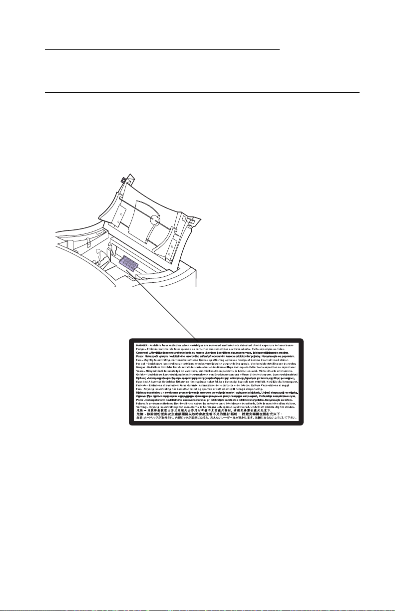
Notices and Safety Information
Laser Notices
The following laser notice labels may be affixed to this printer as
shown:
Notices and Safety Information ix
Page 10

5016-001
Laser Notice
The printer is certified in the U.S. to conform to the requirements of
DHHS 21 CFR Subchapter J for Class I (1) laser products, and
elsewhere is certified as a Class I laser product conforming to the
requirements of IEC 825.
Class I laser products are not considered to be hazardous. The
printer contains internally a Class IIIb (3b) laser that is nominally a 5
milliwatt gallium arsenide laser operating in the wavelength region of
770-795 nanometers. The laser system and printer are designed so
there is never any human access to laser radiation above a Class I
level during normal operation, user maintenance, or prescribed
service condition.
German
Laser
Der Drucker erfüllt gemäß amtlicher Bestätigung der USA die
Anforderungen der Bestimmung DHHS (Department of Health and
Human Services) 21 CFR Teil J für Laserprodukte der Klasse I (1).
In anderen Ländern gilt der Drucker als Laserprodukt der Klasse I,
der die Anforderungen der IEC (International Electrotechnical
Commission) 825 gemäß amtlicher Bestätigung erfüllt.
Laserprodukte der Klasse I gelten als unschädlich. Im Inneren des
Druckers befindet sich ein Laser der Klasse IIIb (3b), bei dem es
sich um einen Galliumarsenlaser mit 5 Milliwatt handelt, der Wellen
der Länge 770-795 Nanometer ausstrahlt. Das Lasersystem und der
Drucker sind so konzipiert, daß im Normalbe tr ie b, bei der Wartung
durch den Benutzer oder bei ordnungsgemäßer Wartung durch den
Kundendienst Laserbestrahlung, die die Klasse I übersteigen würde,
Menschen keinesfalls erreicht.
x Service Manual
Page 11

5016-001
French
Avis relatif à l’utilisation de laser
Pour les Etats-Unis : cette imprimante est certifiée conforme aux
provisions DHHS 21 CFR alinéa J concernant les produits laser de
Classe I (1). Pour les autres pays : cette imprimante répond aux
normes IEC 825 relatives aux produits laser de Classe I.
Les produits laser de Classe I sont considérés comme des produits
non dangereux. Cette imprimante est équipée d’un laser de Classe
IIIb (3b) (arséniure de gallium d’une puissance nominale de 5
milliwatts) émettant sur des longueurs d’onde comprises entre 770
et 795 nanomètres. L’imprimante et son système laser sont conçus
pour impossible, dans des conditions normales d’utilisation,
d’entretien par l’utilisateur ou de révision, l’exposition à des
rayonnements laser supérieurs à des rayonnements de Classe I .
Italian
Avvertenze sui prodotti laser
Questa stampante è certificata negli Stati Uniti per essere conforme
ai requisiti del DHHS 21 CFR Sottocapitolo J per i prodotti laser di
classe 1 ed è certificata negli altri Paesi come prodotto laser di
classe 1 conforme ai requisiti della norma CEI 825.
I prodotti laser di classe non sono considerati pericolosi. La
stampante contiene al suo interno un laser di classe IIIb (3b)
all’arseniuro di gallio della potenza di 5mW che opera sulla
lunghezza d’onda compresa tra 770 e 795 nanometri. Il sistema
laser e la stampante sono stati progettati in modo tale che le
persone a contatto con la stampante, durante il normale
funzionamento, le operazioni di servizio o quelle di assistenza
tecnica, non ricevano radiazioni laser superiori al livello della classe
1.
Notices and Safety Information xi
Page 12

5016-001
Spanish
Avisos sobre el láser
Se certifica que, en los EE.UU., esta impresora cumple los
requisitos para los productos láser de Clase I (1) establecidos en el
subcapítulo J de la norma CFR 21 del DHHS (Departamento de
Sanidad y Servicios) y, en los demás países, reúne todas las
condiciones expuestas en la norma IEC 825 para productos láser de
Clase I (1).
Los productos láser de Clase I no se consideran peligrosos. La
impresora contiene en su interior un láser de Clase IIIb (3b) de
arseniuro de galio de funcionamiento nominal a 5 milivatios en una
longitud de onda de 770 a 795 nanómetros. El sistema láser y la
impresora están diseñados de forma que ninguna persona pueda
verse afectada por ningún tipo de radiac ión láser superior al nivel de
la Clase I durante su uso normal, el mantenimiento realizado por el
usuario o cualquier otra situación de servicio técnico.
Portugese
Declaração sobre Laser
A impressora está certificada nos E.U.A. em conformidade com os
requisitos da regulamentação DHHS 21 CFR Subcapítulo J para a
Classe I (1) de produtos laser. Em outros locais, está certificada
como um produto laser da Classe I, em conformidade com os
requisitos da norma IEC 825.
Os produtos laser da Classe I não são considerados perigosos.
Internamente, a impressora contém um produto laser da Classe IIIb
(3b), designado laser de arseneto de potássio, de 5 milliwatts
,operando numa faixa de comprimento de onda entre 770 e 795
nanómetros. O sistema e a impressora laser foram concebidos de
forma a nunca existir qualquer possiblidade de acesso humano a
radiação laser superior a um nível de Classe I durante a operação
normal, a manutenção feita pelo utilizador ou condições de
assistência prescritas.
xii Service Manual
Page 13

5016-001
Dutch
Laserinformatie
De printer voldoet aan de eisen die gesteld worden aan een
laserprodukt van klasse I. Voor de Verenigde Staten zijn deze eisen
vastgelegd in DHHS 21 CFR Subchapter J, voor andere landen in
IEC 825.
Laserprodukten van klasse I worden niet als ongevaarlijk
aangemerkt. De printer is voorzien van een laser van klasse IIIb
(3b), dat wil zeggen een gallium arsenide-laser van 5 milliwatt met
een golflengte van 770-795 nanometer. Het lasergedeelte en de
printer zijn zo ontworpen dat bij normaal gebruik, bij onderhoud of
reparatie conform de voorschriften, nooit blootstelling mogelijk is
aan laserstraling boven een niveau zoals voorgeschreven is voor
klasse 1.
Danish
Lasermeddelelse
Printeren er godkendt som et Klasse I-laserprodukt, i
overenstemmelse med kravene i IEC 825.
Klasse I-laserprodukter betragtes ikke som farlige. Printeren
indeholder internt en Klasse IIIB (3b)-laser, der nominelt er en 5
milliwatt galliumarsenid laser, som arbejder på bølgelængdeområdet
770-795 nanometer. Lasersystemet og printeren er udformet
således, at mennesker aldrig udsættes for en laserstråling over
Klasse I-niveau ved normal drift, brugervedligeholdelse eller
obligatoriske servi c ebet ing el se r.
Notices and Safety Information xiii
Page 14

5016-001
Finnish
Huomautus laserlaitteesta
Tämä kirjoitin on Yhdysvalloissa luokan I (1) laserlaitteiden DHHS
21 CFR Subchapter J -määrityksen mukainen ja muualla luokan I
laserlaitteiden IEC 825 -määrityksen mukainen.
Luokan I laserlaitteiden ei katsota olevan vaarallisia käyttäjälle.
Kirjoittimessa on sisäinen luokan IIIb (3b) 5 milliwatin
galliumarsenidilaser, joka toimii aaltoalueella 770 - 795 nanometriä.
Laserjärjestelmä ja kirjoitin on suunniteltu siten, että käyttäjä ei
altistu luokan I määrityksiä voimakkaammalle säteilylle kirjoittimen
normaalin toiminnan, käyttäjän tekemien huoltotoimien tai muide n
huoltotoimien yhteydessä.
LUOKAN 1 LASERLAITE
VAROITUS! Laitteen käyttäminen muulla kuin tässä
käyttöohjeessa mainitulla tavalla saattaa altistaa käyttäjän
turvallisuusluokan 1 ylittävälle näkymättömälle lasersäteilylle.
KLASS 1 LASER APPARAT
VARNING! Om apparaten används på annat sätt än i denna
bruksanvisning specificerats, kan användaren utsättas för osynlig
laserstrålning, som överskrider gränsen för laserklass 1.
VARO! Avattaessa ja suojalukitus ohitettaessa olet alttiina
näkymättömälle lasersäteilylle. Älä katso säteeseen.
VARNING! Osynlig laserstrålning när denna del är öppnad och
spärren är urkopplad. Betrakta ej strålen.
xiv Service Manual
Page 15

5016-001
Swedish
Laser-notis
Denna skrivare är i USA certifierad att motsvara kraven i DHHS 21
CFR, underparagraf J för laserprodukter av Klass I (1). I andra
länder uppfyller skr ivaren kraven för laserprodukter av Klass I enligt
kraven i IEC 825.
Laserprodukter i Klass I anses ej hälsovådliga. Skrivaren har en
inbyggd laser av Klass IIIb (3b) som består av en laserenhet av
gallium-arsenid på 5 milliwatt som arbetar i våglängdsområdet 770-
795 nanometer. Lasersystemet och skrivaren är utformade så att det
aldrig finns risk för att någon person utsätts för lasers tr ålning över
Klass I-nivå vid normal användning, underhåll som utförs av
användaren eller annan föreskriven serviceåtgärd.
Norwegian
Laser-melding
Skriveren er godkjent i USA etter kravene i DHHS 21 CFR,
underkapittel J, for klasse I (1) laserprodukter, og er i andre land
godkjent som et Klasse I-laserprodukt i samsvar med kravene i IEC
825.
Klasse I-laserprodukter er ikke å betrakte som farlige. Skriveren
inneholder internt en klasse IIIb (3b)-laser, som består av en
gallium-arsenlaserenhet som avgir stråling i bølgelengdeområdet
770-795 nanometer. Lasersystemet og skriveren er utformet slik at
personer aldri utsettes for laserstråling ut over klasse I-nivå under
vanlig bruk, vedlikehold som utføres av brukeren, eller foreskrevne
serviceoperasjoner.
Notices and Safety Information xv
Page 16

5016-001
Catalàn
Avís sobre el Làser
Segons ha estat certificat als Estats Units, aquesta impressora
compleix els requisits de DHHS 21 CFR, apartat J, pels productes
làser de classe I (1), i segons ha estat certificat en altres llocs, és un
producte làser de classe I que compleix els requisits d’IEC 825.
Els productes làser de classe I no es consideren perillosos. Aquesta
impressora conté un làser de classe IIIb (3b) d’arseniür de gal.li,
nominalment de 5 mil.liwats, i funciona a la regió de longitud d’ona
de 770-795 nanòmetres. El sistema làser i la impressora han sigut
concebuts de manera que mai hi hagi exposició a la radiació làser
per sobre d’un nivell de classe I durant una operació normal, durant
les tasques de manteniment d’usuari ni durant els serveis que
satisfacin les condicions prescrites.
xvi Service Manual
Page 17
5016-001
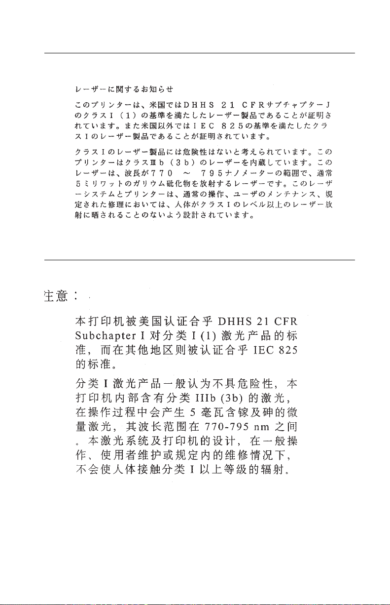
Japanese Laser Notice
Chinese Laser Notice
Notices and Safety Information xvii
Page 18
5016-001
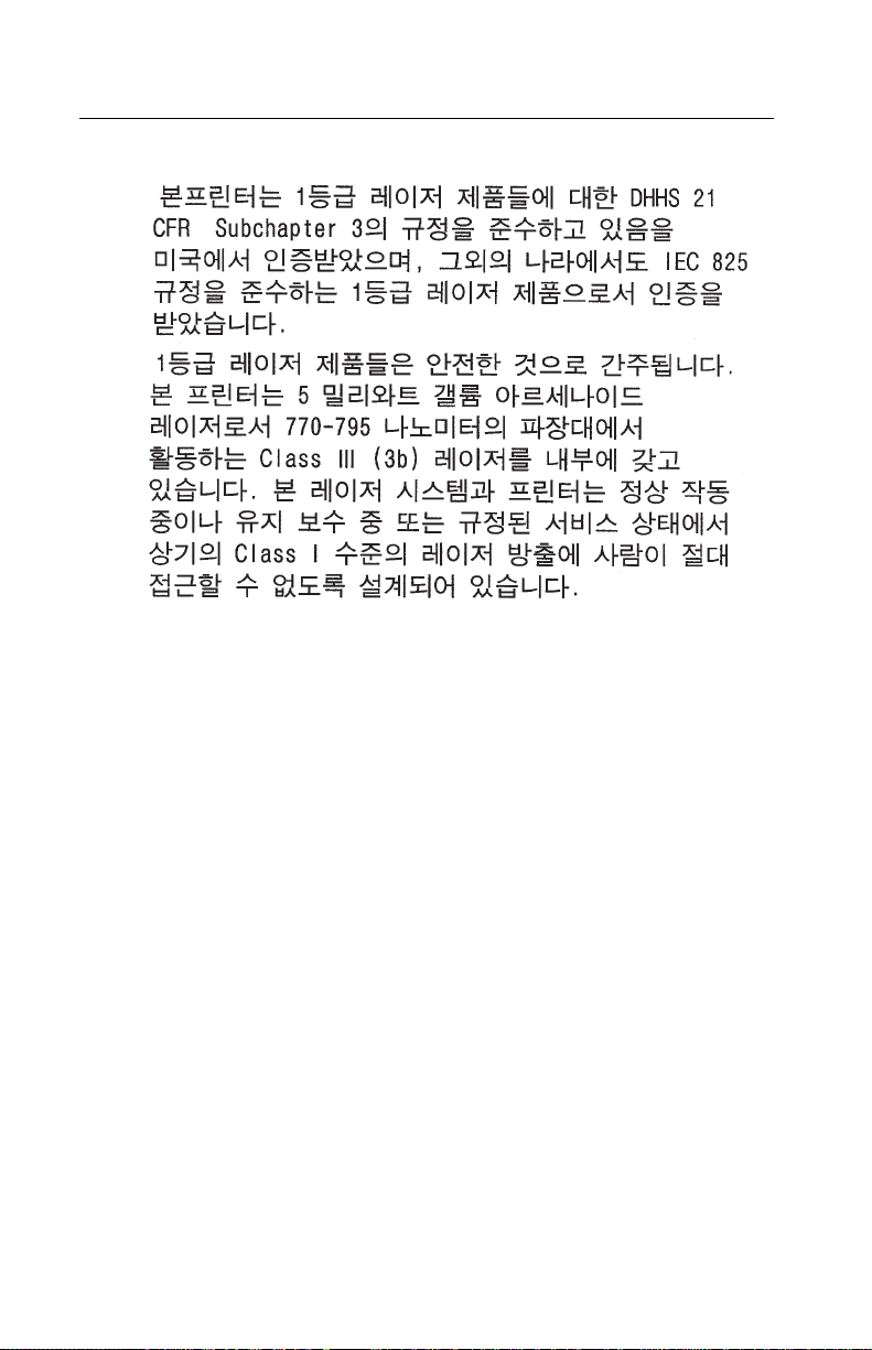
Korean Laser Notice
xviii Service Manual
Page 19

5016-001
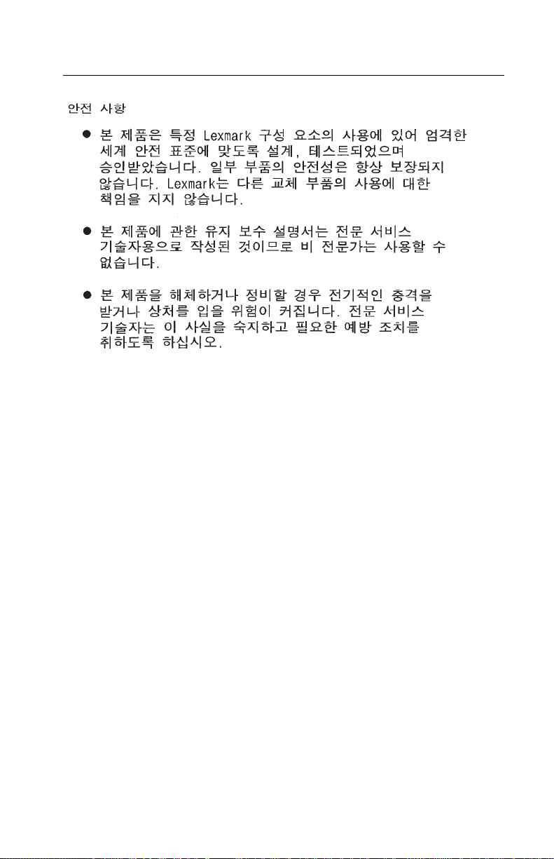
Safety Information
• This product is designed, tested and approved to meet strict
global safety standards with the use of specific Lexmark
components. The safety features of some parts may not always
be obvious. Lexmark is not responsible for the use of other
replacement parts.
• The maintenance information for this product has been
prepared for use by a professional service person and is not
intended to be used by others.
• There may be an increased risk of electric shock and personal
injury during disassembly and servicing of this product.
Professional service personnel should understand this and take
necessar y pr ec autions.
Consignes de Sécurité
French
• Ce produit a été conçu, testé et approuvé pour respecter les
normes strictes de sécurité globale lors de l'utilisation d e
composants Lexmark sp écifiques. Les caractéristiques de
sécurité de certains éléments ne sont pas toujours évidentes.
Lexmark ne peut être tenu responsable de l'utilisation d'autres
pièces de rechange.
• Les consignes d'entretien et de réparation de ce produit
s'adressent uniquement à un personnel de maintenance
qualifié.
• Le démontage et l'entretien de ce produit pouvant présenter
certains risques électriques, le personnel d'entretien qualifié
devra prendre toutes les précautions nécessaires.
Notices and Safety Information xix
Page 20

5016-001
Norme di sicurezza
Italian
• Il prodotto è stato progettato, testato e approvato in conformità
a severi standard di sicurezza e per l’utilizzo con componenti
Lexmark specifici. Le caratteristiche di sicurezza di alcune parti
non sempre sono di immediata comprensione. Lexmark non è
responsabile per l’utilizzo di parti di ricambio di altri produttori.
• Le informazioni riguardanti la manutenzione di questo prodotto
sono indirizzate soltanto al personale di assistenza autorizzato.
• Durante lo smontaggio e la manutenzione di questo prodotto, il
rischio di subire scosse elettriche e danni alla persona è più
elevato. Il personale di assistenza autorizzato, deve, quindi,
adottare le precauzioni necessarie.
Sicherheitshinweise
German
• Dieses Produkt und die zugehörigen Komponenten wurden
entworfen und getestet, um beim Einsatz die weltweit gültigen
Sicherheitsanforderungen zu erfüllen. Die sicherheitsrelevanten
Funktionen der Bauteile und Optionen sind nicht immer
offensichtlich. Sofern Teile eingesetzt werden, die nicht von
Lexmark sind, wird von Lexmark keinerlei Verantwortung oder
Haftung für dieses Produkt übernommen.
• Die Wartungsinformationen für dieses Produkt sind
ausschließlich für die Verwendung durch einen
Wartungsfachmann bestimmt.
• Während des Auseinandernehmens und der Wartung des
Geräts besteht ein zusätzliches Risiko eines elektrischen
Schlags und körperlicher Verletzung. Das zuständige
Fachpersonal sollte entsprechende V orsichtsmaßnahmen
treffen.
xx Service Manual
Page 21

5016-001
Pautas de Seguridad
Spanish
• Este producto se ha diseñado, verificado y aprobado para
cumplir los más estrictos estándares de seguridad global
usando los componentes específicos de Lexmark. Puede que
las características de seguridad de algunas piezas no sean
siempre evidentes. Lexmark no se hace responsable del uso de
otras piezas de recambio.
• La información sobre el mantenimiento de este producto está
dirigida exclusivamente al personal cualificado de
mantenimiento.
• Existe mayor riesgo de descarga eléctrica y de daños
personales durante el desmontaje y la reparación de la
máquina. El personal cualificado debe ser consciente de este
peligro y tomar las precauciones necesarias.
Informações de Segurança
Portugese
• Este produto foi concebido, testado e aprovado para satisfazer
os padrões globais de segurança na utilização de componentes
específicos da Lexmark. As funções de segurança de alguns
dos componentes podem não ser sempre óbvias. A Lexmark
não é responsável pela utiliza ção de outros componentes de
substituição.
• As informações de segurança relativas a este produto
destinam-se a profissio nai s destes serviços e não devem ser
utilizadas por outras pessoas.
• Risco de choques eléctricos e ferimentos graves durante a
desmontagem e manutenção deste produto. Os profissionais
destes serviços devem estar avisados deste facto e tomar os
cuidados necessários.
Notices and Safety Information xxi
Page 22

5016-001
Informació de Seguretat
Catalàn
• Aquest producte està dissenyat, comprovat i aprovat per tal
d'acomplir les estrictes normes de seguretat globals amb la
utililització de components específics de Lexmark. Les
característiques de seguretat d'algunes peces pot ser que no
sempre siguin òbvies. Lexmark no es responsabilitza de l'us
d'altres peces de recanvi.
• La informació pel manteniment d’aquest producte està
orientada exclusivament a professionals i no està destinada a
ningú que no ho sigui.
• El risc de xoc elèctric i de danys personals pot augmentar
durant el procés de desmuntatge i de se rv e i d’aquest producte.
El personal professional ha d’estar-ne assabentat i prendre les
mesures convenients.
Chinese
xxii Service Manual
Page 23
5016-001
Korean
Notices and Safety Information xxiii
Page 24

5016-001
xxiv Service Manual
Page 25
5016-001
1. General Information
The LexmarkTM OptraTM C710 is a letter quality page printer
designed to attach to an IBM-compatible personal computer and
most computer networks.
General Information 1-1
Page 26

5016-001
Models
The 5016-001 printer is available in the following models:
Model Memory INA Options
C710 32 MB N/A N/A
C710n 32 MB 10 Base 100T N/A
C710dn 64 MB 10 Base 100T • Additional 2x250
paper drawer
• Duplex
Standard Features
Feature Description
Printing Process Dry electrophotographic process using a laser diode.
Performance • Monochrome, Letter or A4 - up to 16 ppm.
Special Featu res • Automatic Duplex.
Print
Addressability
• Color, Letter or A4 - up to 3ppm.
• Color transparencies, Letter or A4 - up to 1.8 ppm.
• Monochrome duplexed pages, up to 10 impressions -
5 duplexed ppm.
• Color duplexed pages, up to 3 impressions - 1.5
duplexed ppm.
• Color Quality Enhancement Technology (CQET).
• Automatic color screening selection to optimize print
quality based on print type.
• 4 bit color capabilities.
• Color screens which optimize print quality.
600 x 600 dpi, 1200 x 1200 dpi
Maximum Print
Speed
(Mono/Color)
16/3 ppm (Letter and A4)
1-2 Service Manual
Page 27
5016-001
Feature Description
Maximum
Duplex Print
Speed
(Mono/Color)
Paper Input • Standard 250 sheet integrated input tray
Paper Output Top output bin: 250 sheets
Media Size
Supported
Physical
Characteristics
Power Supply AC 120v, 22v - 240v 60Hz (50Hz)
Power
Consumption
Controller Lexmark Controller
Printer
Management
Software
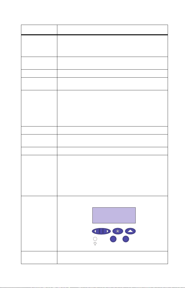
Operator Pa nel Front co ver mounted operator pan el for menus.
5/1.5 ppm (Letter and A4)
• Multip urpose feeder: 50 sheets
A4, B5, Letter, Legal and Executive
• Width: 18.5” (470mm), Depth 25.5” (645mm), Height
16.0” (405mm).
• Height of 2nd drawer: 2 x 250 trays 8.9” (223mm).
• Height of duplex option: 5.7” (145mm).
• Weight: 79 lbs. (35.8kg) for base model only.
• Weight (duplex option) 46.22 lbs. (21kg).
• Weight (dual tray option) 20.7 lbs. (9.4 kg).
1.2 Kw maximum
TM
MarkVision
computer. Supported in the following en v iron ments :
• Windows 95/98
• Windows NT 4.0
• OS/2 Warp
• Macintosh
• UNIX
that lets you m anage y our printer from y our
Exposure
System
• Laser diode
• Scannin g: Polygon scanner
General Information 1-3
Page 28

5016-001
Feature Description
Charging System Corona
Development Non-magnetic mono-component
Fusing System Hot roll fuser 170 degree C
(Hot roll 30mm, backup roll 34mm)
Operating
Temperature
Erase System Light discharge (LED lamp)
• 10 - 35 degrees C (50 - 95 degrees F)
Image Transfer
System
PC Drum Photoconductor: OPC (organic photoconductor)
Cleaning System Blade
Printer Memory • 32MB SDRAM
Interface • Base printer: parallel standard Centronics protocol
Internal
Solutions Ports
Printer Options • Optional paper drawer: drawer unit with two 250 sheet
Internal Print
Servers
• Intermediate trans fer (primary)
• Transfer roller (secondary)
Note: Some models may ship with more memory.
When a duplex unit is installed, 64MB is the
recommended minimum printer memory.
• Maximum usable memory: 384MB
compliant with bidirectional IEEE 1284B.
• Network printer: Ethernet standard connection.
• Three ports for network adapters, tri-port adapters,
parallel port adapters or hard disk.
• Three memory slots.
trays installed underneath the printer.
• Duplex unit: provides two sided color or monochrome
printing.
• Hard disk: 2.5 inch hard disk to store fonts, forms, job
statistics and spooled jobs (4gt limit).
Internal print servers available to support the following
topologies:
• Ethernet 10BaseT and 10Base2.
• Ethernet 10/100Base TX.
• Token-Ring (connects the printer to a Token-Ring
network via DB9 or FJ45).
1-4 Service Manual
Page 29

5016-001
Feature Description
Tr i-port Adapter Provides support for the following interfaces:
• Serial RS-232C/RS-422A (which can also be
configured to support a class 1 Fax modem.
• High speed infrared local connections.
• LocalTalk network connection.
Parallel/USB
Port Adapter
Infrared Adapter For use with the Tri-port adapter. Rec eives infrared bea m
Serial Interface
Adapter
Serial Cable 50-foot serial cable
OptraImage
IEEE 1284 adapter provides additional parallel and USP
port.
from an IrDA-compatible workstation.
• High speed bidirectional 10-foot and 20-foot 1284B
parallel cables
• 9.8-foot 1284 A-C parallel cable
TM
Transforms the printer into an easy-to-use networkable
print/copy station.
General Information 1-5
Page 30

5016-001
Maintenance Approach
The diagnostic information in this manual leads you to the correct
field replaceable unit (FRU) or part. Use the service error codes,
user status messages, user error messages, service checks, and
diagnostic aids to determine the printer problem and repair the
failure. After you complete the repair, perform tests as needed to
verify the repair.
Tools Required For Service
•
Flat-blade screwdriver
• #1 Phillips screwdriver
• #2 Phillips screwdriver
• 7.0 mm nut driver
• 5.5 mm wrench
• Needlenose pliers
• Diagonal pliers
• Spring hook
• Feeler gauges
• Analog or digital multimeter
• Parallel wrap plug 1319128
• Serial wrap plug 1329048
• Twinax /serial debug cable 1381963
• Coax/serial debug cable 1381964
1-6 Service Manual
Page 31

5016-001
Options
The following options are available. Some options are not available
in every country. Contact y our point of purchase for options available
in your country.
• Memory option s: 4MB, 8MB, 16MB, 32MB, 64MB and 128MB
• Flash memory options: 2MB, 4MB, 8MB, 16MB
• Integrated network options:
• Token-Ring
• Ethernet 10/1 00 Base- TX
• Ethernet/PAX card
• Internal IDE disk card
• Ethernet ID Base 2/T
• Tri-Por t:
RS-232C or RS-422 serial
Infrared
LocalTalk
• IPDS
• SCS
• USB/Parallel port
• Ethernet/Fax card
• Ethernet 10/1 00 Base- TX
• Fax modem
• 250/250 dual optional paper tray
• Automatic duplex option
• Hard disk
• Hard disk adapter card
• Optra Forms
TM
hard disk
General Information 1-7
Page 32

5016-001
Operational Theory
Interlock Mechanism
When the front cover assembly, fuser cover or cartridge cover is
open, a CLOSE DOOR message displays indicating the interlock
system is open.
If the front door assembly or the fuser cover are closed, the door
switch actuator 3 [A] moves in the direction of arrow [B].
When the cartridge door is closed the door switch actuator 1 [C]
rotates in the direction shown by arrow [D] and activates the door
switch [E] and laser switch [F].
If either of these doors are not closed, actuator 1 [C] will not rotate
and the switches will not turn on.
When door switch [E] is not activated, it prevents the LVPS from
supplying power to the printer.
When the laser switch [F] is not activated, the engine board will not
turn the printhea d on.
1-8 Service Manual
Page 33

5016-001
Sheet Bypass Paper Feed Unit
Operation of the sheet bypass paper feed unit (multipurpose tray)
When the sheet bypass tray is closed and printing is started,
revolution of the developer/paper feed motor is transmitted to the
clutch gear and timing clutch gear of the sheet bypass paper feed
assembly.
When the bypass paper feed clutch activates, the sheet bypass
paper transfer roll is lowered and touches the paper in the tray.
When the paper transfer roll touches the paper in the paper tray, the
paper is fed into the printer by the actions of the paper transfer roll
and paper feed roll.
As paper is fed to the timing roller by the sheet bypass paper feed
roll, the paper pass sensor detects paper is present. This sensor is
located just prior to the timing roller. After the paper is detected, and
passes through the sensor, the sheet bypass clutch turns off, and
the sheet bypass paper feed and sheet bypass paper transfer roller
stop rotating. At the same time, the paper transfer roller is lifted up
by the return spring so that the paper will touch the timing roll and
wait.
Note: If the transparency paper sensor located in front of the timing
roller detects a transparency, the printer slows to the half speed
mode.
At the same time the image is transferred from the organic photo
conductor (OPC) to the transfer belt, the timing clutch turns on and
the timing roll begins rotating. Paper is then fed into the image
transfer area, registering the image on the sheet of paper.
Double feed prevention
The double feed prevention pad contacts the sheet bypass
paper feed roller at a specific pressure. Whenever multiple sheets of
paper are fed, the bottom sheet is stopped by friction of the double
feed prevention pad, which aids in preventing double feeding. Only
the top sheet of paper is fed by the paper feed roller.
The paper pass sensor checks paper fed from the sheet bypass
paper feed assembly. If the sensor does not detect paper during a
specific time, a paper jam error displays.
General Information 1-9
Page 34

5016-001
Detecting paper present
A sheet of paper in the sheet bypass tray is detected by the sheet
bypass paper detect sensor. When the sheet of paper is detected,
the paper detect sensor turns off. When the sheet of paper is not
detected, the sensor turns on.
1-10 Service Manual
Page 35

5016-001
Paper Feed Unit
Operation of the paper feed unit (tray 1)
When the paper cassette (tray 1) is present in the printer, a flag
molded in the right side of the tray contacts the release lever rotating
the paper transfer roll, allowing it to contact the paper in the tray.
When a print command is sent to the printer, the paper feed clutch,
attached to the paper feed roller turns on, which turns the main
motor transmitting to the clutch gear magnet and the paper feed
gears, causing the paper feed roller and paper transfer roller to turn.
Double feed prevention
The double feed prevention pad contacts the sheet bypass paper
feed roller at a specific pressure.
Whenever multiple sheets of paper are fed, the bottom sheet is
stopped by friction of the double feed prevention pad which aids in
the prevention of double feeding. Only the top sheet of paper is fed
by the paper feed roller.
As paper is fed to the timing roller by the paper feed roll, the paper is
detected by the paper pass sensor located just ahead of the timing
roller. After the paper is detected, the paper feed clutch turns off and
the paper feed roller and paper feed transfer roller stop rotating. At
this point the paper touches the timing roller and remains. The paper
pass sensor checks the paper feed from the cassette; if paper is not
detected the printer stops and a paper jam error displays.
Detecting the paper
Paper in the casette is detected by the paper detect sensor. When
the paper is detected the sensor turns off. If paper is not detected
the sensor remains off.
Detecting paper level
The amount of paper remaining in tray 1 is detected by the paper
detect sensor. When there is enough paper in tray 1 the sensor
remains off. When the level is low, less than 50 sheets, the sensor
turns on and Load Paper tray 1 displays.
General Information 1-11
Page 36

5016-001
Detecting paper size
Paper size is determined by the paper size detect plate connecting
the inner part of the partition plate which detects the paper size
turning on the corresponding switch. It detects Legal, Letter, A4 or
B5/EXE.
1-12 Service Manual
Page 37

5016-001
Second Paper Feed Unit (Optional Paper Trays)
Construction of the Second paper feed option
The second paper feed unit consists of two separate feed units
which are the same as the paper feed unit for tray 1, along with idler
rollers above the paper feed units and paper guides on the side of
the paper feed opening. The interconnect board assembly, drive
module and LVPS for the option is located on the right side frame.
General Information 1-13
Page 38

5016-001
Operation of the Second paper feed unit
When the paper cassette (tray 1) is placed in the printer, a flag
molded to the right side of the tray, contacts the release lever which
rotates the paper transfer roll allowing it to contact the paper in the
tray.
When the command is given to start printing, the optional paper tray
stepper motor rotates, rotating the respective reduction gears. The
rotating reduction gears cause the gears attached to the paper feed
roller and paper transfer roller to start rotating. The paper feed roller
contacts the paper causing the paper to feed to the idler roller. The
one way clutch causes the idler roller to rotate feeding the paper
past the paper pass sensors located prior to the idler roller and the
timing roller. After a predetermined period of time, the paper feed
clutch is turns off and the paper feed roller and paper transfer roller
stop rotating. At this point, the paper stops at the timing roller and
pauses. If the pass thru sensors do not detect paper from the
cassette, a paper jam displays.
1-14 Service Manual
Page 39

5016-001
Detecting the paper
Paper in the casette is detected by the paper detect sensor. When
the paper is detected the sensor is turns off. If paper is not detected
the sensor remains off.
Detecting paper level
The amount of paper remaining in tray 1 is detected by the paper
detect sensor. When there is enough paper in tray 1 the sensor
remains off. When the level is too low, less than 50 sheets, the
sensor turns on and Load Paper tray 1 message displays.
General Information 1-15
Page 40

5016-001
Detecting paper size
Paper size is determined by the paper size detect plate connecting
the inner part of the partition plate. This plate detects the paper size
turning on the corresponding switch. It detects Legal, Letter, A4 or
B5/EXE.
1-16 Service Manual
Page 41

5016-001
Drive Block
Operation of the Drive Block
Note: The Drive Block consists of the paper feed drive block,
developer drive block, fuser drive block, carriage drive block and
OPC/IMT (Intermediate) drive block.
Refer to the drawing for layout of gears and rollers.
In the paper feed system, transmission is switched by three
electromagnetic clutches. In the fuser system a one way clutch is
provided in the center of the paper path to make paper jams easier
to remove from the fuser unit.
The rotation of the contact cam turns on and off by a spring clutch
and solenoid.
General Information 1-17
Page 42

5016-001
Contact Cam
Operation of transferring from the OPC to the transfer belt
The contact cam is stopped at the position shown in figure below.
The pins fit into the grooves of the cam. Lever 1 and lever 2 are
controlled at the position shown. The pin fits into the groove in lever
1 which controls the position of the transfer roller cam, detaching
transfer roller from the transfer belt. The discharge roller is also
detached from the transfer belt at this time. A pin in the side of lever
2 controls the cleaner lever which controls the position of the
cleaner. The cleaner is detached from the transfer belt.
Operation of transferring from the belt to the paper
The contact cam rotates according to the movement of the solenoid
and spring clutch and stops. The revolution of the cam is transmitted
in the following order: transfer roller, discharge roller and cleaner.
1-18 Service Manual
Page 43

5016-001
Coupling Unit
Operation of the coupling unit when initializing or printing
The coupling cam is rotated by the coupling motor. The carriage
position pin slides toward the carriage.
The OPC and carriage are positioned by the movement of the
carriage position pin in the following order:
After initializing or printing, the coupling shaft, detent shaft and
carriage position pin slide in reverse, by rotating the coupling motor
in reverse in order to reset the position of the OPC and carriage.
Manual resetting
By rotating the knob counterclockwise 180 degrees, the same
operation as mentioned above can be performed manually.
General Information 1-19
Page 44

5016-001
1-20 Service Manual
Page 45

5016-001
Carriage Unit
Rotation and stopping operation of the carriage
The carriage rotates by 90 degree angles when switching from one
color to another. The carriage drive motor (pulse motor) tur ns on to
rotate the carriage. After the carriage home position sensor detects
the carriage home position detect rib, the operation is performed as
many times as the specified number of pulses; then the carriage is
stopped at the specified position.
Detecting the carriage
When initializing, the carriage turns one turn so that the carriage
home position sensor can detect the cartridge detect rib located on
the toner cartridge.
Detecting the carriage home position
Four carriage home position detect ribs are located on the carriage
right side plate, one of which is longer that the other three. The
position of respective color toner cartridges is detected by the length
of the ribs while initializing.
General Information 1-21
Page 46

5016-001
Toner Cartridge Unit
Detecting a new cartridge
When initializing, a reflector attached to the new cartridge detect
lever installed in the cartridge, reflects light. A new cartridge detect
sensor installed in the bottom part of the printer, allows the cartridge
to be detected. Once the cartridge has been used the new cartridge
detect lever makes a turn and no additional reflections occur.
A new cartridge dete ct se ns or:
• Will be high “H” when a cartridge has been used. (Sensor
output at connector)
• Will be low “L” when a cartridge is present.
1-22 Service Manual
Page 47

5016-001
Detecting toner level
The toner level sensor is installed in the bottom of the printer and
emits light from infrared LED’s mounted in the sensor assembly, to
mirrors mounted at an angle of the cartridge sensor window.
• No toner in cartridge: Will be high “H”
• Toner left in cartridge: Will be low “L” (toner sensor output at
connector)
General Information 1-23
Page 48

5016-001
Intermediate Transfer Unit
Function of the intermediate transfer unit
The intermediate transfer unit consists of the transfer belt, belt
cleanser and waster toner bottle in which cleaned toner is collected.
The transfer belt is made of an electrically conductive resin. The
toner image, when placed on the organic photoconductor (OPC)
drum is transferred onto the transfer belt by an electric field. The belt
makes four turns, so that four color toner images, yellow (Y),
magenta (M), cyan (C) and black (BK) are transferred onto the belt.
The color image is formed on the transfer belt and the entire image
is transferred onto paper by the transfer roller forming the color
image on the paper.
Note: While the four color toner images are still on the transfer belt
the transfer roller, discharge roller and cleaning roller are pulled
away from the transfer belt. An optical reflector is attached on one
edge of the outer circumference of the transfer belt and is used by
the home position sensor to detect the position of the belt. After the
image is transferred to the paper, any toner remaining on the belt is
cleaned by the cleaning roller and transferred through the transport
coil into the waste toner bottle in the belt unit. When cleaning the
remaining toner, after the image has been transferred to paper, the
transfer roller, discharge roller and cleaning roller, touch the transfer
belt.
1-24 Service Manual
Page 49

5016-001
The waste toner bottle is partitioned and collected toner is
transferred into respective partitions in order. When the bottle is
filled to capacity, it is detected by the waste toner bottle full sensor.
The cleaner consists of the discharge roller, cleaning roller, blade
and toner transport coil. The toner remaining on the belt is
discharged by the discharge roller, transferred to the cleaning roller,
scraped from the cleaning roller by the cleaning blade and
transported to the waste toner bottle by the transport coil.
General Information 1-25
Page 50

5016-001
Operation of the drive for the intermediate transfer unit
The belt gear is rotated by the belt drive gear, rotating the transfer
belt. At the same time the cleaning roller and discharge roller are
rotated by the timing belt and gear. The cleaner lever is shifted by a
pin and the cleaning roller is detached from the transfer belt. At the
same time, the contact pin is shifted by a lever causing the contact
cam to turn. The transfer roller and discharge roller are detached
from the transfer belt by the contact cam.
1-26 Service Manual
Page 51

5016-001
Fuser/Paper Exit Unit
Operation of the fuser and paper exit
When the power switch is turned on the fuser lamp is turned on by
the low voltage power supply while the hot roll begins to heat.
When the hot roll reaches approximately 170 degrees C the fuser
drive motor is turns on and the backup roll, hot roll and paper exit
rollers start turning. After a specified time the fuser drive motor turns
off and the printer is ready to print.
The thermistor continuously detects the temperature of the surface
of the hot roll, turning the fuser lamp on and off keeping the surface
of the hot roll at a specified temperature.
After the last sheet of paper prints and the paper exit sensor detects
the exit of the sheet of paper, the fuser drive motor turns off and the
backup roll, hot roll and paper exit roll stop turning.
A thermostat is provided to protect the fuser unit should an unusual
rise in temperature occur in the hot roll assembly. If activated, the
thermostat shuts off power to the fuser lamp.
A cleaner unit is located on top of the hot roll. The oil roller in the
cleaner unit supplies a specified amount of oil to the hot roll
preventing an offset. The cleaning roller prevents the hot roll from
becoming dirty from a buildup of toner or paper dust.
If power is applied to the fuser unit and a cleaner unit has not been
installed, the paper exit sensor lever is detached from the paper exit
sensor and the printer proceeds to the paper jam state, preventing
the hot roll, backup roll and paper exit roller from rotating.
General Information 1-27
Page 52

5016-001
Detecting New Cleaning Unit
Detecting the cleaning unit in the Fuser Assembly
A thermal fuse is attached on the contact point A in the cleaner unit.
When the cleaner unit is placed inside the fuser unit, contact A
contacts contact B. The circuit is then complete through the thermal
fuse. When primary power is applied to the printer, a current flows
through the thermal fuse detecting a new cleaner unit and the print
counter resets to ‘Zero.’
As the temperature of the hot roll and cleaning roll rise, the
temperature around the thermal fuse also rises, eventually causing
the thermal fuse to blow.
Note: The fuse will generally blow after primary power has been
applied following the printing of two or three sheets of paper. At this
time the temperatures of the blown fuse and surrounding parts are
70 degrees C and about 100 degrees respectively.
When predetermined sheets of paper are printed, a warning
displays. When additional sheets are printed, the printer stops until
the unit is replaced. When a new unit is placed, repeat the previous
step.
1-28 Service Manual
Page 53

5016-001
Duplex Unit (Option)
One side print
The print fed by the paper feed rollers in tray 1 in the printer and in
the second paper feed unit is halted temporarily at the timing roller
for registration. The paper then passes through the transfer unit, in
which the image is formed, and is fused in the fuser assembly . When
the paper exit sensor detects paper, the drive of the automatic two
sided print unit starts, switching the gate claw to the outer side to
eject the page. The paper that is transported by the paper exit roller
in the printer is ejected into the paper exit tray by the paper exit roller
in the duplex unit.
General Information 1-29
Page 54

5016-001
Two sided print
When the printer has been set for two sided print mode and start is
pressed the following occurs:
When the setting is two pages. The paper feed roller in the printer
starts rotating. The paper is transported by the timing roller and the
back page is printed. The paper then passes through the fuser roller.
When the leading edge of the paper reaches the paper exit sensor in
the fuser, the upper unit motor starts rotating in the normal direction,
switching the gate claw to the inner side to receive the paper. When
the paper reaches the upper paper pass sensor, through the paper
transport roller, the rotation of the motor is switched to the
high-speed mode. At the same time, the lower unit motor begins
rotating in the normal direction in the high speed mode, transporting
the paper to the storage area in the lower unit through the rear unit.
1-30 Service Manual
Page 55

5016-001
When the trailing edge of the paper passes through the reverse
sensor filler (S4], the motor rotates in the reverse direction
transporting the paper in reverse. The print is transported to the
timing roller in the printer through the rollers in the curved area, the
skew correction mechanism and the paper feed roller. The paper is
then fed through the transfer and fuser units in sync with the image
of the front page as it is transported onto the middle transfer unit.
When the leading edge of the paper reaches the paper exit sensor
[S0] in the printer, the upper unit motor starts rotating in the reverse
direction, switching the gate claw to the paper exit mode. The paper
then exits through the paper exit roller in the upper unit.
General Information 1-31
Page 56

5016-001
When the setting is four pages
The back page of the first printed page is printed after Print Start is
pressed. The print is received in the upper unit through the above
step and then halted when it reaches the paper exit sensor [S5]
through the storage, reverse and skew correction mechanisms in the
lower unit. The second page is then fed from the selected paper tray
and its back page is printed and transported to the upper unit. The
second page stops when it reaches the upper paper pass sensor
[S2] and is held there. The first page waiting in the lower unit is fed
to the timing roller in the printer. When the timing roller rotates, the
motors in the upper and lower units rotate in high speed mode,
transferring the second page, waiting in the upper unit, to position in
the lower unit. At this time, the front page of the first page is printed
and then exits the printer. The printer then prints the front page of
the second page and finally the second page, as it is finished, exits
the printer.
1-32 Service Manual
Page 57

5016-001
When the setting is not less than six pages or three prints
This operation stages pages in the lower and upper units and
alternates transportation as shown in the preceding steps. These
steps are performed successively.
General Information 1-33
Page 58

5016-001
Exit of the one sided print
When the printed page passes through the paper exit sensor in the
printer, the upper duplex unit motor rotates in the reverse direction,
rotating the gate claw in reverse, so that paper is ejected to the
paper exit tray. When the page passes through the paper exit sensor
in the printer, the upper duplex unit motor rotates in the normal
direction in low speed mode, rotating the gate claw normally in order
to receive the page. When the page passes through the pass
sensor, the motor switches to high speed mode transporting the
page to the duplex rear unit.
1-34 Service Manual
Page 59

5016-001
Detecting the paper exit tray open/close
When the paper exit tray opens to remove a jammed print, the
sensor lever shuts off the open/closed sensor so that detection is
performed.
Detecting the duplex upper unit open/close
When the upper unit opens, the actuator detaches from the right
sensor pin in the right hinge. The actuator, pulled by the return
spring, closes the sensor and detection is performed.
General Information 1-35
Page 60

5016-001
Gate claw operation, when print exits
When the leading edge of a duplexed page prints, it turns the paper
exit sensor in the printer on. The duplex upper unit motor starts
rotating in the reverse direction, rotating the claw gear. The gate
claw rotates counterclockwise feeding the page to the paper exit
roller. The page then exits the printer.
When the leading edge of a simplexed page prints, it actuates the
paper exit sensor and the duplex upper unit motor rotates in the
normal direction. This rotation is then transmitted to the claw gear
and limiter disk and the gate claw rotates in a clockwise direction so
that the page can print on the opposite side.
1-36 Service Manual
Page 61

5016-001
Storage of the paper in the duplex unit
The page that is transported from the duplex rear unit pushes on the
gate claw and is stored in the duplex lower tray unit. When the
trailing edge of the page passes through gate claw 2, gate claw 2 is
rotated by the gate claw spring until the gate claw lever touches the
stopper, switching to reverse paper exit mode.
General Information 1-37
Page 62

5016-001
Operation of the motor
When the leading edge of the paper reaches the paper pass sensor
in the duplex upper unit, the upper unit motor goes into high speed
mode (270m/sec). At this time, the duplex lower unit motor rotates in
the normal direction. The rotation is transmitted to the gears in the
lower unit as shown. When the leading edge of the paper reaches
the paper pass sensor [S3], the duplex upper unit motor stops
rotating.
1-38 Service Manual
Page 63

5016-001
When the page is transported from the duplex rear unit for storage,
the reverse sensor detects the paper. After the sensor detects the
paper, for a specified time, the motor turns off and the print is stored.
The duplex lower unit reverse motor supplies drive to the duplex rear
unit and tray through gear 18Z. When the duplex tray is pulled out,
the interlock switch opens and interrupts the circuit to the reverse
motor. The tray condition sensor detects the position of the duplex
tray and whether it is correctly installed. The transport sensor
detects whether the page being transported passes though to the
printer.
General Information 1-39
Page 64

5016-001
When paper is fed from the 2nd paper option, the chassis side input
gear rotates in [B] direction. The drive is transmitted to the one way
gear 16Z through the store roller drive shaft, rotating the one way
gear 16Z in the [B] direction.
Note: Drive is not transmitted when the rotation is in the [A]
direction, due to the one way clutch [A]. The timing belt drives,
turning the idler rollers in the [B] direction, while transporting the
page in the [B] direction.
1-40 Service Manual
Page 65

5016-001
Skew Correction
The holder mounted on the lower side of the rear cover is inclined
about 3 degrees, in the paper pass direction. The page is brought to
the opposite side of the skew correction mechanism in the duplex
lower tray unit by this inclination for the preparation of skew
correction. To mount the holder, engage the tab of the holder with
the second groove from the rib of the rear cover.
General Information 1-41
Page 66

5016-001
Acronyms
CSU Customer Setup
DRAM Dynamic Random Access Memory
EDO Enhanced Data Out
EP Electrophotographic Process
EPROM Erasable, Programmable Read-Only Memory
ESD Electrostatic Discharge
FRU Field Replaceable Unit
GB Giga Byte
HVPS High Voltage Power Supply
LASER Light Amplification Stimulated Emission of Radiation
LCD Liquid Crystal Display
LED Light-Emitting Diode
LV PS Low Voltage Power Supply
MROM Masked Read Only Memory
NVRAM Nonvolatile Random Access Memory
OEM Original Equipment Manufacturer
PC Photoconductor
RIP Raster Imaging Processor
ROM Read Only Memory
SIMM Single In-Line Memory Module
SRAM Static Random Access Memory
UPR Used Parts Return
V ac Volts alternating current
V dc Volts direct current
1-42 Service Manual
Page 67

5016-001
2. Diagnostic Information
Start
CAUTION: Remove power from the printer before you connect or
disconnect any cable, electronic board or assembly, for personal
safety and to prevent damage to the printer. Always use the hand
grips on the side of the printer and be sure your fingers are not
under the printer when you set the printer down.
Use the service error codes, user status messages, user error
messages, symptom tables, service checks, and diagnostic aids, to
determine the corrective action necessary to repair a malfunctioning
printer.
Service error codes are indicated by a three-digit error code. If a
service error code displays, go to the “Service Error Codes” on
page 2-2.
User status messages provide the user with information on the
current status of the printer. “Ready” displays on the first line of the
display unless Power Saver is invoked, then Power Saver is
displayed. If a user status message displays, go to the “User Status
Messages” on page 2-7.
User error messages are indicated by a two or three digit error code
which provides the user with information explaining a problem with a
print cartridge, paper jam, option, port, and so on. If a user error
message displays, go to the “User Attendance Messages” on
page 2-13.
If you have a failing symptom, go to the “Symptom Tables” on
page 2-28. Locate your symptom and take the appropriate action.
If a service error code appears while you are working on the printer,
go to the “Service Error Codes” on page 2-2 and take the
appropriate action.
Diagnostic Information 2-1
Page 68

5016-001
Service Error Codes
Service Error Codes are generally non-recoverable except in an
intermittent condition, when you can POR the printer to temporarily
recover from the error condition.
Error Code Action
900 RIP Software Contact your customer service center, or the Lexmark
910 DC Motor (1) Locking error - the motor did not stabilize. Go to the
911 DC Motor (2) Locking error - the motor did not stabilize. Go to the
912 DC Motor The motor stabilized then locking was released. Go to
917 Transfer Belt Go to the “ITM Drive Service Check” on page 2-60.
918 Fan Stalled The main fan has stalled, or locked up. Go to the “Main
Customer Support Center.
“OPC Drive Service Check” on page 2-66.
“Developer/Paper Feed Motor Service Check” on
page 2-48.
the “Devel oper/Paper Feed M otor Servi ce Check” on
page 2-48.
Fan Service Check” on page 2-62.
Note: The following errors are detected when the printer is below
the maintenance count.
920 Fuser Error Indicates that the fuser is below temperature when
921 Fuser Error Indicates that the fuser is below temperature and the
printing. Go to the “Fuser Cold Service Check” on
page 2-51.
system is detecti ng a the rmist or s hort. Go to t he “Fuser
Cold Service Check” on page 2-51.
922 Fuser Error Indicates that the fuser temperature failed to increase.
923 Fuser Error Fuser is too hot during printing or when printer is idle. Go
924 Fuser Error Indicates that the system has detected that the
Go to the “Fuser Cold Service Check” on page 2-51.
to the “Fuser Hot Service Chec k” on page 2-57.
thermistor is open. Go to the “Fuser Hot Service
Check” on page 2-57.
2-2 Service Manual
Page 69

5016-001
Error Code Action
Note: The following errors are detected when the printer is above
the maintenance count. As the fuser assembly is a CRU
(customer replaceable unit) and is contained in the maintenance
kits, ask if the customer has replaced the fuser CRU, or if he/she
has installed a maintenance kit recently.
925 Fuser Error Indicates that the fuser is below temperature when
printing.
926 Fuser Error Indicates that the fuser is below temperature and the
927 Fuser Error Indicates that the fuser temperature failed to increase.
928 Fuser Error Indicates that the fuser is too hot during printing, or when
929 Fuser Error Indicates that the system has detected that the
930, 931, 934,
935
Printhead Error
939 RIP Engine
Communications
Error
• 941
Controller
Code CRC
• Controlle r F ont
CRC
system is detecting a thermistor short.
the printer is idling.
thermistor is open.
Go to the “Printhead Service Check” on page 2-77.
Indicates that the RIP board and the engine board
cannot communicate. The RIP board, engine board or
cabling may be defective. Check each board for correct
installation and be sure all grounds are secure. If no
problem exis ts, replace the follo wing FRUs in the order
shown:
• Engine board
• Controller board
• Interconnect board
Note: It is possi b le that the RI P softwa re can also cause
a 929 error. Contact your next level for software support.
Replace the controller board.
943 RIP
Font Version
Indicates that the font ROM and RIP code are
incompatible.
Diagnostic Information 2-3
Page 70

5016-001
Error Code Action
948 Engine
Board
953 NVRAM
Failure
954 NVRAM
CRC Failure
955 Font CRC Indicates that the font ROM failed the CRC check.
956 System
Board
957 ASIC Failure
(Controller Board)
958 ASIC Failure
(Engine Board)
959 SRAM
Failure
Indicates that the engine board microprocessor has
stopped. Replace the engine board assembly. Go to the
“Engine Board Assembly Removal” on page 4-19.
Indicates the NVRAM failed the CRC chec k. Replace the
engine board assembly. Go to the “Engine Board
Assembly Removal” on page 4-19.
Indicates the engine board NVRAM failed the CRC
check. Replace the engine board assembly. Go to the
“Engine Board Assembly Removal” on page 4-19.
Replace the code overlay SIMM.
Indicates that there was a microprocessor failure on the
controller board. Replace the controller board assembly.
Go to the “Controller Board Assembly Removal” on
page 4-19.
Indicates that ther e wa s an ASI C f a ilure o n t he con trolle r
board. Replace the controller board assembly. Go to the
“Controller Board Assembly Removal” on page 4-19.
Indicates that ther e wa s an ASI C f a ilure o n t he con trolle r
board. Replace the controller board assembly. Go to the
“Controller Board Assembly Removal” on page 4-19.
Indicates that there was an SRAM failure on the
controller board. Replace the controller board assembly.
Go to the “Controller Board Assembly Removal” on
page 4-19.
960 RAM
Memory Error
961 RAM
Memory Error
962 RAM
Memory Error
2-4 Service Manual
Indicates that the RAM soldered on the controller board
is defective. Replace the controller board assembly. Go
to the “Controller Board Assembly Removal” on
page 4-19.
Indicates that the DRAM installed in slot 1 on the
controller board is defective. Replace the DRAM SIMM.
If this does not fix the problem, replace the controller
board assembly. Go to the “Controller Board
Assembly Removal” on page 4-19.
Indicates that the DRAM installed in slot 2 on the
controller board is defective. Replace the DRAM SIMM.
If this does not fix the problem, replace the controller
board assembly. Go to the “Controller Board
Assembly Removal” on page 4-19.
Page 71

5016-001
Error Code Action
963 Memory
Error
964 Emulation
Error
965 Emulation
Error
975 Network
Card X
976 Network
Card X
978 Network
Card X
Indicates that the DRAM installed in slot 3 on the
controller board is defective. Replace the DRAM SIMM.
If this does not fix the problem, replace the controller
board assembly. Go to the “Controller Board
Assembly Removal” on page 4-19.
Indicates that the do wnload em ulatio n CRC has failed. A
checksum failure was detected in the emulation header
or emulation file. Replace the code overlay SIMM.
Indicates that the download emulation is outdated. Time
stamps indicate that the download emulation and
controller code are incompatible.
• Disable the download emulation.
• Program the download emulation into the code
overlay SIMM.
• If the above steps do not fix the problem, replace the
code overlay SIMM and re-download the emu la tion.
Indicates that a failure has occurred with the network
card installed in slot x (x=1, 2 or 3).
Indicates an unrecognizable network card x. Replace
network card x.
Indicates that a bad checksum has been detected while
programming network card x. Replace network card x.
979 Network
Card X
990 Coupling
Operation Error
991 Coupling
Sensor Error
992 High Voltage
Leakage
Indicates that flash parts failed while programming
network card x. If this is a network m odel p rinter, replace
the controller board. Go to the “Controller Board
Assembly Removal” on page 4-19.
A failure has occurred in the coupling operation. Go to
the “Coupling Unit Service Check” on page 2-42.
Coupling sensor 1 and 2 have tu rned on s imultaneously.
Go to the “Coupling Unit Service Check” on
page 2-42.
The high voltage leakage detection circuit has detected
leakage in the high voltage system. Go to the “High
Voltage Leakage Detect Service Check” on
page 2-58.
Diagnostic Information 2-5
Page 72

5016-001
Error Code Action
993 Cam Sensor
does not turn on
994 Engine
EEPROM Error
The cam sensor did not ac tiv ate. Go to the “Fuser Drive
and Contact Cam System Service Check” on
page 2-53.
An engine EEPROM error has been detected.
2-6 Service Manual
Page 73

5016-001
User Status Messages
Message Status Action
Ready The printer is ready to
Power Saver When your printer is in
Warming Engine The printer is warming the
Performing Self
Test
Busy The printer is processing or
Flushing Buffer The printer is flushing
receive and process data.
power saver mode, the
Power Saver message
replaces the
message on the display.
When
displayed, your printer is
ready to receive and
process data.
fuser to prepare for
printing.
The printer is running the
normal series of start-up
tests it performs after it is
turned on.
printing data. (The light on
the operator panel flashes
while this message is
displayed.) If a job name
has been defined, the
name replac es the Busy
message on the display.
corrupted print data and
the current print job is
being discarded.
Ready
Power Saver is
If the printer has an internal
fax modem, the Ready/Fax
icon is also displayed.
Power Saver is
When
displayed, you can:
• Press
• Press
N/A
N/A
To cancel the print job,
press
When the Job Menu is
displayed, press
Press
until Cancel Job appears
on the second line. Press
Select.
No button actions are
possible while this
message is displayed.
Go to quick start
the printer.
Menu> or <Menu
to enter the menus.
Menu> or <Menu.
Select.
Menu> or <Menu
Diagnostic Information 2-7
Page 74

5016-001
Message Status Action
Waiting The printer has received a
page of data to print but is
waiting f or an End of Job or
Form Feed co mmand or f or
additional data.
Not Ready The printer is not ready to
receive or process data ,
because someon e selected
Stop when another
message was displ ayed.
Ready Hex Hex Trace diagnostic mode
is active, and the printer is
ready to receive data.
Use Hex Trace to isolate
the source of a print job
problem. With Hex Tr ace
selected, all data sent to
the printer is printed in
hexadecimal and character
representation.
Control code strings are
printed, not ex ec uted.
• To print the contents of
the print buffer, press
Go.
• To cancel the print job,
press
Menu> or <Menu
until the Job Menu is
displayed. Press
Press
Menu> or <Menu
Select.
until Cancel Job appea rs
on the second line.
Select.
Press
• Press
Go to remove the
printer from the Not
Ready state.
• To cancel the print job,
Menu> or <Menu
press
until the Job Menu is
displayed. Press
Menu> or <Menu
Press
Select.
until Cancel Job appea rs
on the second line.
Select.
Press
• To exit Hex Trace mode,
turn the printer off or
reset the printer.
• To reset the printer,
Menu> or <Menu.
press
When the Job Menu is
displayed press
Menu> or <Menu
Press
Select.
until Reset Printer
appears on the second
line. Press
Select.
Locking Menus Someone has locked the
menus. While the menus
are locked, users cannot
change the printer default
settings from the operator
panel.
2-8 Service Manual
N/A
Page 75

5016-001
Message Status Action
Unlocking Menus Someone has unloc k ed the
Disabled Menu Menus have been locked,
Enabled Menu Menus have been
Supplies At least one of the printer
Activating Menu
Changes
Parallel The standard parallel
Parallel x The specifie d parallel
menus. Users can now
change the printer default
settings from the operator
panel.
or disabled.
unlocked.
supplies needs attenti on .
You may have a paper tray
that is low on paper or a
print cartridge that needs
replacing.
This message is displayed
when the printer is being
reset. To activate some of
the printer settings, the
printer must restart. No
buttons are active when
this message is displayed.
interface is the act ive
communication link.
interface is the act ive
communication link.
N/A
N/A
N/A
Menu> or <Menu to
Press
open the Supplies Menu.
N/A
N/A
N/A
Serial x The specifi ed serial
interface is the act ive
communication link.
Network x The specified network
interface is the act ive
communication link.
LocalTalk x The LocalTalk interface is
the active communication
link.
Infrared x The infrared interf ace is the
active communication link.
Fax The fax interface is the
active communication link.
N/A
N/A
N/A
N/A
N/A
Diagnostic Information 2-9
Page 76

5016-001
Message Status Action
Cancelling Job The printer is processing a
Resetting the
Printer
Flushing Buffer The printer is flushing
Queuing Jobs This message is displayed
Deleting Jobs This message is displayed
request to cancel the print
job.
The printer is deleting any
print jobs in progress and
restoring all print settings to
the user defaults.
corrupted print data and
discarding the current print
job. No buttons are active
when this message is
displayed.
after an operator ha s exited
the CONFIDENTIAL JOB
or HELD JOBS operation
and has marked one or
more Print and Hold jobs
for printing or selected the
Print All Jobs option. No
buttons are active when
this message is displayed.
after an operator ha s exited
the CONFIDENTIAL JOB
or HELD JOBS operation
and has marked one or
more Print and Hold jobs
for deletion or selected the
Delete All Jobs option. No
buttons are active when
this message is displayed.
N/A
N/A
N/A
N/A
N/A
This message may appear
with the Queuing Jobs
message if one or more
Print and Hold jobs have
been selected for printing
and deletion.
2-10 Service Manual
Page 77

5016-001
Message Status Action
Printing Menu
Settings
A list of user default
settings and installed
options is printing.
Printing Font List A list of available fonts for
the selected printer
language is printing.
Printing Directory
List
A list of all files stored in
flash memory or on the
hard disk is printing.
Printing Job
Accounting Stat
An accumulated statistics
report for the most recent
print jobs is printing.
To cancel the print job,
Menu> or <Menu.
press
The Job Menu is displayed.
Menu> or <Menu
Press
until Cancel Job appears
on the second line. Press
Select.
To cancel the print job,
Menu> or <Menu.
press
The Job Menu is displayed.
Menu> or <Menu
Press
until Cancel Job appears
on the second line. Press
Select.
To cancel the print job,
press Menu> or <Menu.
The Job Menu is displayed.
Menu> or <Menu
Press
until Cancel Job appears
on the second line. Press
Select.
To cancel the print job,
press
Menu> or <Menu.
The Job Menu is displayed.
Menu> or <Menu
Press
until Cancel Job appears
on the second line. Press
Select.
Clearing Job
Accounting Stat
The printer is delet ing all
job statistics stored on the
optional disk.
Restoring Factory
Defaults
The printer is restoring
factory defaul ts. See
“Restore EP Factory
Defaults” on page 3-22
for details about which
printer settings are
affected. No buttons are
active when this message
is displayed.
Formatting Flash The printer is formatting the
flash memory. No buttons
are active when this
message displays.
N/A
N/A
Do not turn the printer off
while this message
displays.
Diagnostic Information 2-11
Page 78

5016-001
Message Status Action
Programming
Flash
Defragmenting
Flash
The printer is
formatting the
hard disk.
The printer is
storing resources
on the hard disk.
The network
adapter is being
reset.
The printer is storing
resources in flash memory.
The printer is performing
the defragmentation
operation on fl ash memory.
This operation is used to
reclaim flash memory
space occupied by deleted
resources. No buttons are
active when this message
is displayed.
The printer is formatting the
hard disk. N o buttons are
active when this message
is displayed.
The printer is storing
resources on the hard d isk.
The Network x Setup menu
is not available while this
message displays.
Do not turn the printer off
while this message is
displayed.
Do not turn the printer off
while this message is
displayed.
Do not turn the printer off
while this message
displays.
Do not turn the printer off
while this message
displays.
N/A
2-12 Service Manual
Page 79

5016-001
User Attendance Messages
Message Status Action
Close Door The printer’s front cover,
fuser cover, or cartridge
cover is open.
Insert Tray x The tray is not inserted. Insert the tray indicated (tray
Change Media The printer is requesting a
different size or type
media than what it detec ts
is in the identified tray
(tray 1, 2, 3, or the
multipurpose feeder). The
message display s eith er
the custom media name
defined using the
MarkVision utility, the
media size, or the media
size and type it is looking
for.
Close the printer’s front
cover, fuser cover, or
cartridge cover.
1, 2, or 3).
To clear the message:
If the correct paper type is
loaded in the tray (b ut the
Paper Type setting was not
changed from the operator
panel), press
printing.
Press
request and print on the
media already install ed in
the tray.
Load media of the
requested size and type in
the tray indicated.
To cancel the print job.
• Press
The Job Menu i s
displayed.
• Press
until Cancel Job appears
on the second line.
• Press
Go to continue
Select to ignore the
Menu> or <Menu.
Menu> or <Menu
Select.
Diagnostic Information 2-13
Page 80

5016-001
Message Status Action
Load Media This attendance message
indicates the type of
media selected is not
available in the source
tray y o u w an t to print fro m
or the paper type
indicated by the Paper
Menu does not match the
type or size of the media
you have requested to
print on.
This message will display
either the custom media
name defined using the
MarkVision utility, the
media size, or the media
size and type it is looking
for.
Tray x Empty The printer is trying to
feed paper from a source
it detects is empty (tray 1,
2, 3, or the multipurpose
feeder). The mess ag e
displays ei ther the cu stom
media name defined us ing
the MarkVision utility, the
media size, or the media
size and type it is looking
for.
To clear the message:
If the correct paper type is
loaded in the tray (but the
Paper Type setting was not
changed from the operator
panel), press
Go to continue
printing.
Press
Select to ignore the
request and print on the
media already installed in
the tray.
Load media of the
requested size and type in
the tray indicated.
To cancel the print job.
• Press
Menu> or <Menu
until the Job Menu is
displayed.
• Press
Select. Press
Menu> or <Menu until
Cancel Job appears on
the second line.
• Press
Select.
To clear the message, load
media of the requested size
and type in the tray
indicated.
To cancel the print job:
• Press
Menu> or <Menu.
The Job Menu i s
displayed.
• Press
Menu> or <Menu
until Cancel Job appears
on the second line.
• Press
Select.
2-14 Service Manual
Page 81

5016-001
Message Status Action
Load Manual You have sent a request
for a manual feed job t o
the printer, a nd th e prin ter
is ready for y ou to insert a
single sheet or envelope
into the multipurpose
feeder. The message
displays either th e custo m
media name defined using
the MarkVision utility, the
media size, or the media
size and type it is looking
for.
No Jobs Found
Retry?
This attendance message
occurs if you have entered
a PIN (Personal
Identification Number) to
print or delete a
Confidential Print Job and
your PIN is n ot assoc iated
with any Confidential Print
Job currently stor ed i n th e
printer.
To clear the message, load
media of the requested size
and type in the multipurpose
feeder. Press
Select or Go
to ignore the manual feed
request and print on media
already installed in one of
the paper sources. If the
printer finds a tray that has
media of the correct size
and type, it feeds media
from that tray. If the printer
cannot find a tray with the
correct media size an d type ,
it prints on whatever media
is installed in the default
paper source.
To cancel the print job.
• Press
Menu> or <Menu.
The Job Menu i s
displayed.
• Press
Menu> or <Menu
until Cancel Job appears
on the second line.
• Press
• Press
Select.
Go to enter another
PIN.
• Press
Return or Stop to
exit the PIN entry
operation.
Print Jobs on
Disk?
Jobs that were spooled to
the optional hard disk
before the printer was last
turned off have not yet
printed.
• Press
• Press
Go to print the jobs.
Return or Stop to
delete the jobs from the
disk without printing
them.
Diagnostic Information 2-15
Page 82

5016-001
Message Status Action
Delete All Jobs
Go/Stop?
Files Will be Lost
Go/Stop?
Invalid Font Data The printer has detected
Invalid Network x
Code
30 Color Toner
Missing
This message is displa ye d
when you have selected
all CONFIDENTIAL JOBS
or HELD JOBS for
deletion. This message
warns the user this
operation results in the
deletion of all confidential
or held print jobs.
You have chang ed the Job
Buffer Size setting from
the operator panel, and
the printer must reformat
the hard disk to activate
the change.
an incompatibil ity between
the font data and the
firmware.
The code in the specified
network adapter has not
been programmed or is
invalid.
The specified cartridge
(Cyan, Magenta, Yellow,
or Black) is not installed in
the printer.
You must take one of the
follow i ng ac tion s:
• Press
• Press
If you press
currently stored on the disk
will be deleted.
Press
cancel this operation.
You mus t download
compatible font data to flash
memory before the printer
can return to the ready
state.
You mus t download valid
code to the network adapt er
before the printer can return
to the ready state.
Insert the cartridge and
close the cartridge cover to
clear the message.
Return or Stop to
cancel the delete
operation.
Go to validate the
option and delete all
confidential or held jobs.
Go, all files
Return or Stop to
2-16 Service Manual
Page 83

5016-001
Message Status Action
35 Res Save Off
Deficient Memory
37 Insufficient
Collation Area
The printer lacks the
memory needed to enable
the Resource Save
function. This message
usually indicates that too
much memory is allocat ed
for one or more of the
printer link buffers.
The printer memory (or
optional hard disk, if
installed) does not ha ve
the space necessary to
collate the print job.
To disable Resource Save
and continue printin g, press
Go.
To enable Resource Save
after you get this message ,
perform one of the following:
• Set the link buffer for
each interface to Auto.
Then exit the menus to
activate the link b u ffer
changes. When the
Ready message is
displayed, enable
Resource Save from the
Setup Menu.
• Install additional printer
memory.
Go to print the portion
Press
of the job already stored and
begin collating the rest of
the job.
To cancel the print job:
• Press
Menu> or <Menu
until the Job Menu is
displayed.
• Press
Menu> or <Menu
until Cancel Job appears
on the second line.
• Press
Select.
37 Insufficient
Defrag Memory
The printer is unable to
perform the r equested
Flash Memory
Defragment operation
because the printer does
not have enough memory.
This message is posted
before the operation
begins to ensure items in
flash memory are not lost.
Go to clear the
Press
message.
If you want to perform the
defragment operation,
delete fonts, macros, and
other data in RAM and try
again or install more
memory.
Diagnostic Information 2-17
Page 84

5016-001
Message Status Action
37 Insufficient
Memory
Held Jobs ma y be
Lost. Go/Stop?
The printer is unable to
perform the requested
Print and Hold operation
because the printer does
not have enough memory.
38 Memory Full The printer is processing
the job, but the memory
used to store pages is f ull.
• Press
Go to clear the
message. Th e printer
starts to free memory by
deleting the oldest held
job and cont inues
deleting held jobs until
enough memory has
been freed to proc ess the
incoming job.
• Press
Stop to clear the
message. Incoming data
that was not stored is lost.
Go to clear the
Press
message and continue
printing. Some data ma y no t
print or may no t print
correctly.
Cancel the print job. Pr ess
Menu> or <Menu. The Job
Menu is displayed. Press
Menu> or <Menu until
Cancel Job appears on the
second line. Press
Select.
To reduce the complexity of
the job:
2-18 Service Manual
• Reduce the number of
graphics or images on a
page.
• Delete unnecessary
downloaded fonts or
macros.
• Change the Print Quality
setting.
Install additional printer
memory to avoid future
Memory Full errors.
Page 85

5016-001
Message Status Action
39 Complex Page The text, graphics, and
print information on the
page require more
memory to print than what
you have installed in your
printer.
51 Defectiv e
Flash
The flash card installed in
your printer is defective.
• Press
Go to clear the
message and continue
printing. Some data may
not print or may not print
correctly.
• Cancel the print job.
Menu> or <Menu.
Press
The Job Menu i s
displayed. Press
<Menu until Cancel
or
Menu>
Job appears on the
second line. P res s
Select.
To avoid another Complex
Page error:
• Set P age Pro tect On fro m
the Setup Menu and
resend the job.
• Reduce the complexity of
the page by using fewer
fonts, macros, and
graphics.
• Install additional printer
memory.
Go to clear the
Press
message and continue
printing. You must install a
different flash card before
you can perform any flash
functions.
Diagnostic Information 2-19
Page 86

5016-001
Message Status Action
52 Flash Full There is not enough
space available to hold
the resources you want to
store in flash memory.
53 Unformatted
Flash
The flash memory
installed in your printer
has not been formatted.
You must format the flash
memory before
downloading resources.
54 Serial Option x
Error
The printer has dete cted a
protocol error on the
specified serial interface.
Be sure the serial
interface par am et ers are
set up correctly and you
are using an appropriate
serial cable.
Go to clear the
Press
message and continue
processing. Dow nl oad ed
fonts and macros not
previously stored in flash
memory or disk are deleted.
To reset the printer:
• Press
Menu> or <Menu.
The Job Menu i s
displayed.
• Press
Menu> or <Menu
until Reset Printer
appears on the second
line.
• Press
Press
Select.
Go to clear the
message. To format flash
memory, select Format
Flash from the Utilities
Menu.
Go to clear the
Press
message and continue
printing. The job may not
print correctly.
To reset the printer:
• Press
Menu> or <Menu.
The Job Menu i s
displayed.
• Press
Menu> or <Menu
until Reset Printer
appears on the second
line.
• Press
Select.
2-20 Service Manual
Page 87

5016-001
Message Status Action
54 Serial x Fax
Connection Lost
54 Std Par ENA
Connection Lost
54 Network x
Software Error
The printer has detected
the external modem that
was once connected to
the serial port is no longer
responding. If the printer
has been configured to
receive faxes from a serial
port and the Fax P ort
setting is not set to
disabled, it polls the
modem. If it detects the
modem connection is
missing, it displays the
attendance message. If
the modem connection is
re-established, the printer
removes the message
from the display.
An External Network
Adapter (ENA) that was
once connected to the
standard paral lel port is no
longer responding. The
printer only recognizes the
missing connection when
the printer power is first
turned on.
The printer software ha s
detected that a network
port is installed and
cannot establi sh
communications with it.
If the modem has been
intentionally disconnected,
you can press
the message and continue
printing.
• Be sure the cable
connecting the ENA and
the printer is securely
attached.
• Turn the printer off and
then on again to see if the
printer recognizes the
connection.
• Press
message. The printer
erases any reference to
the ENA and then resets.
Press Go to clear the
message. The printer
disables all communications
to the associated network
interface. No data can be
transmitted through this
interface. You can program
new firmware in the netwo rk
interface through the
parallel port after this
message clears.
Go to clear
Go to clear the
Diagnostic Information 2-21
Page 88

5016-001
Message Status Action
54 Par x ENA
Connection Lost
55 Insufficient F ax
Buffer
An External Network
Adapter (ENA) that was
once connected to the
specified parallel port is
no longer responding. The
printer only recognizes the
missing connection when
the printer power is first
turned on.
This attendance message
may appea r if the printer is
processing a print job . The
printer must complete the
print job before processing
the fax data. If the fax
buffer is not large enough
to hold the fax data, this
message is displa yed.
After this message is
posted, the printer breaks
the phone connection with
the sending fax printer.
The ability of the printer to
process fax data exceeds
the data transmis s ion ra te
of most fax printers.
• Be sure the cable
connecting the ENA and
the printer is securely
attached. Turn the printer
off and then on again to
see if the printer
recognizes the
connection.
• Press
Go to clear the
message. Th e printer
erases any reference to
the ENA and then resets.
Go to clear the
Press
message and continue
processing the curr ent print
job.
To reset the printer:
• Press
Menu> or <Menu
until the Job Menu is
displayed.
• Press
Menu> or <Menu
until Reset Printer
appears on the second
line.
• Press
Select.
56 Std Parallel
Port Disabled
Data was sent to the
standard parallel port, but
the port has been disa bled
from the Parallel Buffer
menu item.
2-22 Service Manual
Go to clear the
Press
message. The printer
discards the data sent t o the
parallel port.
To reset the printer:
• Press
Menu> or <Menu.
The Job Menu i s
displayed.
• Press
Menu> or <Menu
until Reset Printer
appears on the second
line.
• Press
Select.
Page 89

5016-001
Message Status Action
56 Parallel Port x
Disabled
56 Serial x Port
Disabled
Data was sent to the
specified parallel port, but
the port has been disabled
from the parallel buf fer
menu item.
Data was sent to the
specified serial port, but
the port has been disabled
from the serial buff er
menu item.
Go to clear the
Press
message. The printer
discards the data sent to the
parallel port.
To reset the printer:
• Press
Menu> or <Menu
until the Job Menu is
displayed.
• Press
Menu> or <Menu
until Reset Printer
appears on the second
line.
• Press
Press
Select.
Go to clear the
message. The printer
discards the data sent to the
serial port.
To reset the printer:
• Press
Menu> or <Menu
until the Job Menu is
displayed.
• Press
Menu> or <Menu
until Reset Printer
appears on the second
line.
• Press
Select.
58 T oo Many
Disks Installed
58 T oo Many
Flash Options
You have more than one
hard disk installed.
You have more than one
flash option installed.
Turn the printer off and
follow the instructions in
your Setup Guide for
installing an optional hard
disk.
Turn the printer off and
follow the instructions in
your Setup Guide for
installing and remo ving flash
memory.
Diagnostic Information 2-23
Page 90

5016-001
Message Status Action
61 Defective Disk The hard disk installed in
your printer is defective.
62 Disk Full There is not enough
space available to hold
the resources you want to
store on disk.
63 Unformatted
Disk
The hard disk installed in
your printer has not been
formatted. You must
format the disk before you
can download resources
to it.
Press Go to clear the
message and continue
printing. You must install a
different di sk bef ore y ou ca n
perform any disk functi ons.
Go to clear the
Press
message and continue
processing. Dow nl oad ed
fonts and macros not
previously stored in flash
memory or disk are deleted.
To reset the printer:
• Press
Menu> or <Menu.
When the Job Menu is
displayed press
• Press
Menu> or <Menu
Select.
until Reset Printer
appears on the second
line.
• Press
Press
Select.
Go to clear the
message. If the error
message remains, the disk
may be defective and need
replacing.
To format the disk, select
Format Disk from the
Utilities Menu.
64
Disk not in Slot 3
If you place an optional
hard disk in slot 1 or 2, th is
message appears on the
operator panel. The
optional hard di sk m ust be
placed in slot 3 for the
printer to operate. If you
have another adapter in
slot 3, move it to slot 1 or
2 and place the hard disk
in slot 3.
2-24 Service Manual
Refer to your Setup Guide
for information on installing
an optional hard disk in your
printer.
Note: Do not attempt to
remove or install the hard
disk with the printer power
on or the power cord
connected.
Page 91

5016-001
Message Status Action
70–79 Network Reserved for messages
relating to the optional
print server sometimes
referred to as an Internal
Network Adapter (INA)
installed in your printer.
83 Transfer Belt
Life Warning
This message indicates
the waste toner area is
full.
84 Transfer Belt
Life Warning
This message indicates
the transfe r belt is nearing
its end of life. The transfer
belt is a part of the
transfer kit. If you do not
have an extra transfer kit,
order it now.
84 Transfer Belt
Exhausted
This message indicates
the transfer belt is
exhausted and must be
replaced.
85 Coating Roll
Life Warning
This message indicates
the coating roll is nearing
its end of life or empty
condition. Normally the
coating roll is replaced
when you replace the
black print cartridge. It is
possible, depending on
the type of print jobs you
send to the printer, a
coating roll may have to
be replaced prior to the
print cartridge becoming
low on toner. If you do not
have an extra coating roll,
order it now.
For more information, refer
to the online documentation
included on the printer CD
under “Network Printing.”
If you suspect a false waste
toner full condition has
occurred, you can clean the
waste toner sensor.
Go to clear the
Press
message and continue
printing. The
Supplies
status message displays
with the
Saver
Ready, Power
, Busy and Waiting
messages, unless another
status message of higher
priority is posted, or until
you replace the transfer b elt .
A new transfer belt must be
installed to clear this error
message.
Go to clear the
Press
message and continue
printing. The
Supplies
status message is displays
with the
Saver
Ready, Power
, Busy and Waiting
messages, unless another
status message of higher
priority is posted, or until
you replace the coating roll.
Note: Continued use of the
coating roll after th e warning
has been displayed may
result in poor toner ad hesion
to print media, other print
quality problems, and paper
jams.
86 Transfer Belt
Missing
The transfer belt is not
installed in the printer.
Insert the transfer belt and
close the front co v er to clear
the message.
Diagnostic Information 2-25
Page 92

5016-001
Message Status Action
87 Fuser
Exhausted
This message indicates a
new fuser kit must be
installed. If you do not
have the fuser kit, order it
now.
88 Color Low This message indicates
the color print cartridge
indicated is nearing its
end of life or empty
condition. If you do not
have an appr opriate extra
print cartr idge, order it
now.
88 Color Cartridge
Empty
The printer has detected
the specified print
cartridge is completely out
of toner.
Go to clear the
Press
message and continue
printing. The fuser
exhausted intervention
message is posted every
time the printer power is
turned on.
When a new fuser is
installed, you must reset the
fuser counter to zero. To
reset the fuser counter:
1. Turn the printer off.
2. Press and hold the
Return buttons on
and
Select
the operator panel while
turning the printer on. The
Configuration Menu
displays on the opera tor
panel.
3. Press
Menu> or <Menu
Reset Fuser Count
until
appears on the second
line.
4. Press
Select to reset the
fuser counter to zero.
Go to clear the
Press
message and continue
printing. The
Supplies
status message displays
with the
Saver
Ready, Power
, Busy and Waiting
messages, unles s anot her
status message of higher
priority is posted, or until
you replace the print
cartridge.
You must install a new print
cartridge before you can
continue printing.
2-26 Service Manual
Page 93

5016-001
Message Status Action
20x Paper Jam The printer has detected a
23x Paper Jam
Check Duplex
24x Paper Jam
Check Tray x
25x Paper Jam
MP Feeder
paper jam in the area
specified in the message.
The printer has detected a
paper jam in the duplex
unit.
The printer has detected a
paper jam in the tray
specified in the message.
The printer has detected a
paper jam in the
multipurpose feeder.
You must remove the paper
from the entire paper path.
Close any open covers and
press Go to clear the
message.
You must remove the paper
from the entire duplex unit
paper path. Close any open
covers and the duplex tray.
Press Go to clear the
message.
If the duplex unit is not
plugged in, the printer
displays
Check Duplex
Remove the paper from the
paper path. Close any open
trays or covers. Press Go to
clear the message.
Remove the paper from the
multipurpose feeder and
paper path. Close any open
covers. Press Go to clear
the message.
230 Paper Jam
.
Diagnostic Information 2-27
Page 94

5016-001
Symptom Tables
Base Printer Symptom Table
Symptom Action
Operator panel - One or more
buttons do not work.
Operator panel - Display is blank.
Printer sounds 5 beeps.
Operator Panel - Display is blank.
Printer does not emit 5 beeps.
Operator panel continuously
displays all diamonds - 5 beeps.
Paper feed problems - Base
printer or Integrated 250 Paper
Tray.
Paper jams
Duplex option not installed.
Paper jams
Duplex option installed.
Print quality - Black page. Go to “All Black or Color Page
Print quality - Blank page. Go to “All Blank Page Service
Print quality - Light print. Go to “Lo w Ima ge Density Service
Go to the “Operator Panel Buttons
Service Check” on page 2-65.
Go to the “Operator Panel Service
Check” on page 2-64.
Replace the operator panel
assembly.
Go to the “Operator Panel Service
Check” on page 2-64.
Go to the “Paper Feed Service
Check” on page 2-68.
Go to the “Paper Feed Service
Check” on page 2-68.
Go to the “Duplex Unit Option
Service Check” on page 2-120.
Service Check” on page 2-80.
Check” on page 2-81.
Check” on page 2-87.
Print quality - Background. Go to “Background Service
Check” on page 2-82.
Print quality - Residual image. Go to “Residual Image Service
Print quality - Skew. Go to the “Paper Feed Service
Print quality - Banding. Go to “White Lines or Bands
Check” on page 2-90.
Check” on page 2-68.
Service Check” on page 2-92.
2-28 Service Manual
Page 95

5016-001
Symptom Action
Print quality - Random marks. Go to “Random Marks Service
Print quality - Toner on backside of
printed page.
Print quality - Vertical black bands
on edge of copy.
Check” on page 2-90.
Go to “Toner on Backside of Page
Service Check” on page 2-91.
Go to “Black, Color Lines or
Bands Service Check” on
page 2-83.
Covers Interlock Symptom Table
Symptom Action
Close Door displays when all
covers are not properly latched.
Go to the “Cover Interlock Service
Check” on page 2-45.
Duplex Unit Symptom Table
Symptom Action
Paper feed problem with duplex.
Paper jams at paper removal tray.
Paper skews in the duplex option.
Go to the “Duplex Unit Option
Service Check” on page 2-120.
Paper fails to pass from lower
option through the duplex option.
Diagnostic Information 2-29
Page 96

5016-001
Operator Panel Symptom Table
Symptom Action
Operator panel - one or more
buttons do not work.
Operator panel - display is blank
and the printer beeps five times.
Operator panel - display is blank
and the printer does not beep.
Operator panel continuously
displays all diamonds and beeps
five times.
Go to the “Operator Panel Buttons
Service Check” on page 2-65.
Go to the “Operator Panel Service
Check” on page 2-64.
Replace the operator panel. Go to
the “Operator Panel Cover
Removal” on page 4-3.
Go to the “Operator Panel Service
Check” on page 2-64.
Paper Feed Symptom Table
Symptom Action
Paper does not feed from the
integrated tray 1.
Paper jam:
• ITM area
• In fuser assembly
• In ex it assem bly
• 201 displays
• 202 displays
Go to the “Paper Feed Service
Check” on page 2-68.
Go to the “Paper Feed Service
Check” on page 2-68.
Printer does not feed media
correctly from multipurpose tray.
Printer does not detect:
• Media in tray 1
• Level of media in tray 1
• Size of media in tray 1
• Presence of tray 1
2-30 Service Manual
Go to the “Bypass Tray
(Multipurpose Tray) Service
Check” on page 2-35.
Go to the “Tray 1 (Integrated Tray)
Service Check” on page 2-99.
Page 97

5016-001
Paper Tray Options Symptom Tab l e
Symptom Action
Paper feed problem with 250/250
Sheet Paper Tray Option.
Media fails to pass thru from the
lower attached paper tray option
to the next higher mounted option.
Paper jam 242 or 243 displays Go to the “Paper Feed Service
Printer does not detect:
• Media in tray 2 or tray 3
• Level of media in tray 2 or tray
3
• Size of media in tray 2 or tray 3
• Presence of tray 2 or tray 3
Go to the “Options Service
Checks” on page 2-106.
Go to the “Options Service
Checks” on page 2-106.
Check” on page 2-68.
Go to the “Options Service
Checks” on page 2-106.
Power Symptom Table
Symptom Action
No indication the printer is
functioning.
• No LEDs on
• Display off
• No motor movement
Go to the “Power Servi ce Ch eck”
on page 2-72.
Operator panel LED indicator on.
• Printer inoperative
• POR incomplete
Main fan does not run. Go to the “Main Fan Service
Go to the “Power Servi ce Ch eck”
on page 2-72.
Check” on page 2-62.
Diagnostic Information 2-31
Page 98

5016-001
Print Quality Symptom Table
Symptom Action
All black page Go to the “All Black or Color Page
Blank page Go to the “All Blank Page Service
Light print Go to the “Low Image Density
Background Go to the “Background Service
Residual image Go to the “Residual I ma ge Service
Skew Go to the “Skew Service Che ck”
Black, color or bands Go to the “Black, Color Line s or
Random marks Go to the “Random Marks Service
Toner on back of paper Go to the “Toner on Backside of
Offset image Go to the “Offset Print Service
Service Check” on page 2-80.
Check” on page 2-81.
Service Check” on page 2-87.
Check” on page 2-82.
Check” on page 2-90.
on page 2-91.
Bands Service Check” on
page 2-83.
Check” on page 2-90.
Page Service Check” on
page 2-91.
Check” on page 2-88.
Uneven image density Go to the “Uneven Print Density
Foggy background Go to the “Foggy Background
White spots Go to the “White Spots Service
White lines or bands Go to the “White Lines or Bands
Black or color lines and bands Go to the “Black, Color Lines or
Service Check” on page 2-92.
Service Check” on page 2-86.
Check” on page 2-94.
Service Check” on page 2-92.
Bands Service Check” on
page 2-83.
2-32 Service Manual
Page 99

5016-001
Symptom Action
Poor color reproduction Go to the “Poor Color
Black or color spots Go to the “Black or Color Spots
Scratch marks parallel to paper
feed direction
Reproduction Service Check” on
page 2-89.
Service Check” on page 2-84.
Replace the fuser assembly. Go to
the “Fuser Unit Removal” on
page 4-23.
Diagnostic Information 2-33
Page 100

5016-001
Service Checks
Note: Anytime the controller board is replaced, the Configuration ID
must be reset in NVRAM on the new controller board. Go to
“Setting Configuration ID” on page 3-20.
Review the following information before performing any service
checks.
• Paper feed Problems (especially paper jams): Go to “Viewing
the Error Log” on pa ge 3-22 and check the printer error log for
indications of repetitive entries that help to isolate a problem to
a particular area of the printer or option.
• Print Quality Problems: Go to “Print Quality Test Pages” on
page 3-9 and print a test page to help diagnose problems
before changing any settings or working on the printer.
• Use the resident diagnostic tests to help isolate a problem
before taking the printer apart or removing any options.
2-34 Service Manual
 Loading...