

Page 1

Lexmark Optra™ Color 45
• Table of Contents
• Start Diagnostics
• Safety and Notices
• Trademarks
4080-001
•Index
• Manuals Menu
Lexmark and Lexmark with diamond
design are trademarks of Lexmark
International, Inc., registered in the
United States and/or other countries.
Page 2

4080-001
Edition: October 2000
The following paragraph does not apply to any country where such provisions are
inconsistent with local law: LEXMARK INTERNATIONAL, INC. PROVIDES THIS
PUBLICATION “AS IS” WITHOUT WARRANTY OF ANY KIND,EITHER EXPRESS OR
IMPLIED,INCLUDING, BUT NOT LIMITED TO, THE IMPLIED WARRANTIES OF
MERCHANTABILITY OR FITNESS FOR A PARTICULAR PURPOSE. Some states do
not allow disclaimer of express or implied warranties in certain transactions, therefore, this
statement may not apply to you.
This publication could include technical inaccuracies or typographical errors. Changes are
periodically made to the information herein; these changes will be incorporated in later
editions. Improvements or changes in the products or the programs described may be
made at any time.
CommentsmaybeaddressedtoLexmarkInternational,Inc.,DepartmentD22/035-2,
740 New Circle Road N.W., Lexington, Kentucky 40550, U.S.A. Lexmark may use or
distribute any of the information you supply in any way it believes appropriate without
incurring any obligation to you. Youcan purchase additional copies of publications related
to this product by calling 1-800-553-9727. In other countries, contact your point of
purchase.
Lexmark and Optra are trademarks of Lexmark International, Inc., registered in the United
States and/or other countries.
Other trademarks are the property of their respective owners.
©CopyrightLexmarkInternational,Inc.1998, 2000.
All rights reserved.
UNITED STATES GOVERNMENT RESTRICTED RIGHTS
This software and documentation are provided with RESTRICTED RIGHTS. Use,
duplication or disclosure by the Government is subject to restrictions as set forth in
subparagraph (c)(1)(ii) of the Rights in Technical Data and Computer Software clause at
DFARS252.227-7013 and in applicable FAR provisions: Lexmark International, Inc.,
Lexington, KY 40550.
Page 3

4080-001
Table of Contents
GeneralInformation....................................1-1
Power Consumption .....................................1-1
Maintenance Approach ..................................1-1
Tools Required For Service ...............................1-1
Abbreviations ..........................................1-2
Operator Panel and Menus ...............................1-3
Using the Operator Panel...............................1-3
Printer Indicator Light..................................1-3
Operator Panel Buttons ................................1-4
Printer Messages .....................................1-5
Operator Panel Menus ...................................1-6
Printing the Menu Settings Page .........................1-7
Changing Printer Settings ..............................1-8
Disabling the Operator Panel Menus ......................1-9
DiagnosticInformation .................................2-1
Start .................................................2-1
Error Indicator Table ..................................2-2
Power-On Self Test (POST) Sequence ....................2-4
Post Symptom Table ..................................2-5
Symptom Tables .....................................2-6
Service Checks ........................................2-9
Controller Board Service Check..........................2-9
Encoder Card / Strip Service Check ......................2-9
End of Forms (EOF) Service Check......................2-10
Maintenance Station Service Check .....................2-10
Noisy Paper Feed Motor Service Check ..................2-11
Operator Panel (Buttons) Service Check..................2-11
Operator Panel (LCD) Display Service Check ..............2-12
Options Service Check................................2-13
Paper Feed Service Check ............................2-15
Paper Path Service Check.............................2-18
Power Service Check.................................2-19
Print Quality Service Check ............................2-21
Transport Service Check ..............................2-24
Transport Service Check II.............................2-25
Tray 2 Service Check.................................2-25
User Error Messages.................................2-27
DiagnosticAids .......................................3-1
iii
Page 4

4080-001
Diagnostic Mode ........................................3-1
Aligning the Cartridges ...................................3-2
Cleaning the Printheads ..................................3-2
Paper Lifters Operation Theory .............................3-2
Error Log ..............................................3-3
Viewing the Error Log ..................................3-3
Clearing the Error Log..................................3-3
Hardware Tests .........................................3-4
LCD Test ............................................3-4
Button Test ..........................................3-4
DRAM Memory Test ...................................3-5
ROM Memory Test ....................................3-6
Parallel Wrap Test.....................................3-6
Serial Wrap Test ......................................3-7
Device Tests ...........................................3-8
Hex Trace ...........................................3-8
Quick Disk Test.......................................3-8
Disk Test/Clean.......................................3-9
Flash Test ..........................................3-10
Printer Setup ..........................................3-11
Setting the Page Count ................................3-11
Viewing the Permanent Page Count ......................3-11
Restore Factory Defaults...............................3-12
Print Tests ............................................3-12
Print Quality Test Page ................................3-13
Printing Menu Settings Page............................3-14
Test Page (Quick Test) ..................................3-15
RepairInformation......................................4-1
Handling ESD-Sensitive Parts ..............................4-1
Adjustments ............................................4-2
Removal Procedures .....................................4-2
Releasing Plastic Latches...............................4-2
Covers and Doors .......................................4-3
Base Assembly Removal ...............................4-4
Code SIMM Access Door Removal........................4-4
Controller Board Access Cover Removal ...................4-5
Controller Board Access Door Removal ....................4-5
Envelope Guide Removal ...............................4-5
Front Access Door Removal .............................4-6
Front Cover Removal ..................................4-6
Gutter Pad Removal ...................................4-6
Memory (SIMM) Card Cover Removal .....................4-7
iv Service Manual
Page 5

4080-001
Metal / Plastic Controller Board Cover Removal .............4-7
Operator Panel Cover Removal..........................4-8
Option Card(s) Cover Removal ..........................4-8
Rear Cover Removal ..................................4-8
Rear Access Cover Removal............................4-9
Frames ..............................................4-10
Carrier Frame Assembly Removal.......................4-11
Carrier Rail Removal .................................4-11
Idler Pulley Assembly Removal .........................4-12
Left Side Frame Assembly Removal .....................4-12
Mid Frame Assembly Removal .........................4-13
Right Side Frame Assembly Removal ....................4-13
Paper Feed ...........................................4-14
Exit Roller Assembly Removal..........................4-15
Gear Box Assembly Removal ..........................4-15
Large Feed Roller Removal ............................4-15
Manual Sheet Feeder Removal .........................4-16
Paper Feed Motor Removal............................4-16
Paper Lifters Removal ................................4-16
Paper Tray Assembly Removal .........................4-17
Small Feed Roller Assembly Removal....................4-17
Small Feed Roller Holder Assembly Removal ..............4-17
Star Roller Assembly Removal .........................4-17
Electronics ...........................................4-18
Code or Flash SIMM Removal..........................4-19
Controller Board Removal .............................4-20
Encoder / Thermistor Card Removal .....................4-21
Engine Board Removal ...............................4-22
Memory (SIMM) Card Removal .........................4-22
Operator Panel Removal ..............................4-24
Operator Panel Cable Removal .........................4-25
Option Card(s) Removal ..............................4-25
Power Supply Removal ...............................4-26
Tray 2 Sensor Removal ...............................4-26
Carrier ..............................................4-27
Carrier Belt Removal .................................4-28
Carrier Rail Removal .................................4-28
Carrier Transport Motor Assembly Removal ...............4-29
Encoder Strip / Retainer Removal .......................4-29
Printhead Carrier Removal.............................4-30
Maintenance Station ....................................4-31
Maintenance Station Assembly Removal..................4-32
Wipers and Caps Removal ............................4-32
v
Page 6

4080-001
ConnectorLocations....................................5-1
Engine Board ...........................................5-1
Controller Board ........................................5-2
Preventive Maintenance .................................6-1
Lubrication Specifications .................................6-1
PartsCatalog ..........................................7-1
HowToUseThePartsCatalog.............................7-1
Assembly 1: Covers ......................................7-2
Assembly 2: Frames......................................7-4
Assembly 3: Paper Feed ..................................7-6
Assembly 4: Electronics ..................................7-8
Assembly 5: Carrier .....................................7-10
Assembly 6: Carrier Transport .............................7-12
Assembly 7: Maintenance Station ..........................7-14
Assembly 8: Options.....................................7-16
Index.................................................I-1
vi Service Manual
Page 7

4080-001
Safety Information
• This product is designed, tested and approved to meet strict
global safety standards with the use of specific Lexmark
components. The safety features of some parts may not always
be obvious. Lexmark is not responsible for the use of other
replacement parts.
• The maintenance information for this product has been
prepared for use by a professional service person and is not
intended to be used by others.
• There may be an increased risk of electric shock and personal
injury during disassembly and servicing of this product.
Professional service personnel should understand this and take
necessary precautions.
Consignes de Sécurité
• Ce produit a été conçu, testé et approuvé pour respecter les
normes strictes de sécurité globale lors de l'utilisation de
composants Lexmark spécifiques. Les caractéristiques de
sécurité de certains éléments ne sont pas toujours évidentes.
Lexmark ne peut être tenu responsable de l'utilisation d'autres
pièces de rechange.
• Les consignes d'entretien et de réparation de ce produit
s'adressent uniquement à un personnel de maintenance
qualifié.
• Le démontage et l'entretien de ce produit pouvant présenter
certains risques électriques, le personnel d'entretien qualifié
devra prendre toutes les précautions nécessaires.
vii
Page 8

4080-001
Norme di sicurezza
• Il prodotto è stato progettato,testato e approvato in conformità a
severi standard di sicurezza e per l’utilizzo con componenti
Lexmark specifici. Le caratteristiche di sicurezza di alcune parti
non sempre sono di immediata comprensione. Lexmark non è
responsabile per l’utilizzo di parti di ricambio di altri produttori.
• Le informazioni riguardanti la manutenzione di questo prodotto
sono indirizzate soltanto al personale di assistenza autorizzato.
• Durante lo smontaggio e la manutenzione di questo prodotto, il
rischio di subire scosse elettriche e danni alla persona è più
elevato. Il personale di assistenza autorizzato, deve, quindi,
adottare le precauzioni necessarie.
Sicherheitshinweise
• Dieses Produkt und die zugehörigen Komponenten wurden
entworfen und getestet, um beim Einsatz die weltweit gültigen
Sicherheitsanforderungen zu erfüllen. Die sicherheitsrelevanten
Funktionen der Bauteile und Optionen sind nicht immer
offensichtlich. Sofern Teile eingesetzt werden, die nicht von
Lexmark sind, wird von Lexmark keinerlei Verantwortung oder
Haftung für dieses Produkt übernommen.
• Die Wartungsinformationen für dieses Produkt sind
ausschließlich für die Verwendung durch einen
Wartungsfachmann bestimmt.
• Während des Auseinandernehmens und der Wartung des
Geräts besteht ein zusätzliches Risiko eines elektrischen
Schlags und körperlicher Verletzung. Das zuständige
Fachpersonal sollte entsprechende Vorsichtsmaßnahmen
treffen.
viii Service Manual
Page 9

4080-001
Pautas de Seguridad
• Este producto se ha diseñado, verificado y aprobado para
cumplir los más estrictos estándares de seguridad global
usando los componentes específicos de Lexmark. Puede que
las características de seguridad de algunas piezas no sean
siempre evidentes.Lexmark no se hace responsable del uso de
otras piezas de recambio.
• La información sobre el mantenimiento de este producto está
dirigida exclusivamente al personal cualificado de
mantenimiento.
• Existe mayor riesgo de descarga eléctrica y de daños
personales durante el desmontaje y la reparación de la
máquina. El personal cualificado debe ser consciente de este
peligro y tomar las precauciones necesarias.
Informações de Segurança
• Este produto foi concebido, testado e aprovado para satisfazer
os padrões globais de segurança na utilização de componentes
específicos da Lexmark. As funções de segurança de alguns
dos componentes podem não ser sempre óbvias. A Lexmark
não é responsável pela utilização de outros componentes de
substituição.
• As informações de segurança relativas a este produto
destinam-se a profissionais destes serviços e não devem ser
utilizadas por outras pessoas.
• Risco de choques eléctricos e ferimentos graves durante a
desmontagem e manutenção deste produto. Os profissionais
destes serviços devem estar avisados deste facto e tomar os
cuidados necessários.
ix
Page 10

4080-001
Informació de Seguretat
• Aquest producte està dissenyat, comprovat i aprovat per tal
d'acomplir les estrictes normes de seguretat globals amb la
utililització de components específics de Lexmark. Les
característiques de seguretat d'algunes peces pot ser que no
sempre siguin òbvies. Lexmark no es responsabilitza de l'us
d'altres peces de recanvi.
• La informació pel manteniment d’aquest producte està
orientada exclusivament a professionals i no està destinada a
ningú que no ho sigui.
• El risc de xoc elèctric i de danys personals pot augmentar
durant el procés de desmuntatge i de servei d’aquest producte.
El personal professional ha d’estar-ne assabentat i prendre les
mesures convenients.
x Service Manual
Page 11
4080-001
xi
Page 12

4080-001
xii Service Manual
Page 13

4080-001
1. General Information
The Lexmark OptraTMColor 45 printer is a network, near laserquality inkjet printer. The print cartridge contains single-unit
customer-replaceable supply items. Dual printheads provide color
and true black printing without changing printheads. The black
cartridge has a total of 208 nozzles and installs on the left. The color
cartridge has a total of 192 nozzles and installs on the right. The
printer is capable of printing in two directions from either cartridge.
Power Consumption
• 13 Watts - Idle Mode (power on - not printing)
• 21 Watts - Printing (average)
Maintenance Approach
The diagnostic information in this manual leads you to the correct
field replaceable unit (FRU) or part. Use the error indicator charts,
symptom index, service checks, and diagnostic aids to determine
the symptom and repair the failure.
This printer can be serviced without being connected to a host
computer. The user is directed, in the Printer Control program, to
perform the head to head and bidirectional alignment adjustments
after replacing a print cartridge.
After you complete the repair, perform tests as needed to verify the
repair.
Tools Required For Service
• Analog or digital multimeter
• Coax/serial debug cable P/N 1381964
• Parallel wrap plug P/N 1319128
• Pliers: diagonal and needle-nose
• Screwdrivers: #1 and #2 Phillips
• Twinax/serial debug cable P/N 1381963
General Information 1-1
Page 14

4080-001
Abbreviations
EOF End of Forms
ESD Electrostatic Discharge
FRU Field Replaceable Unit
LED Light-Emitting Diode
POST Power-On Self Test
SIMM Single In-line Memory Module
RAM Random Access Memory
ROM Read Only Memory
V ac Volts alternating current
V dc Volts direct current
1-2 Service Manual
Page 15
4080-001
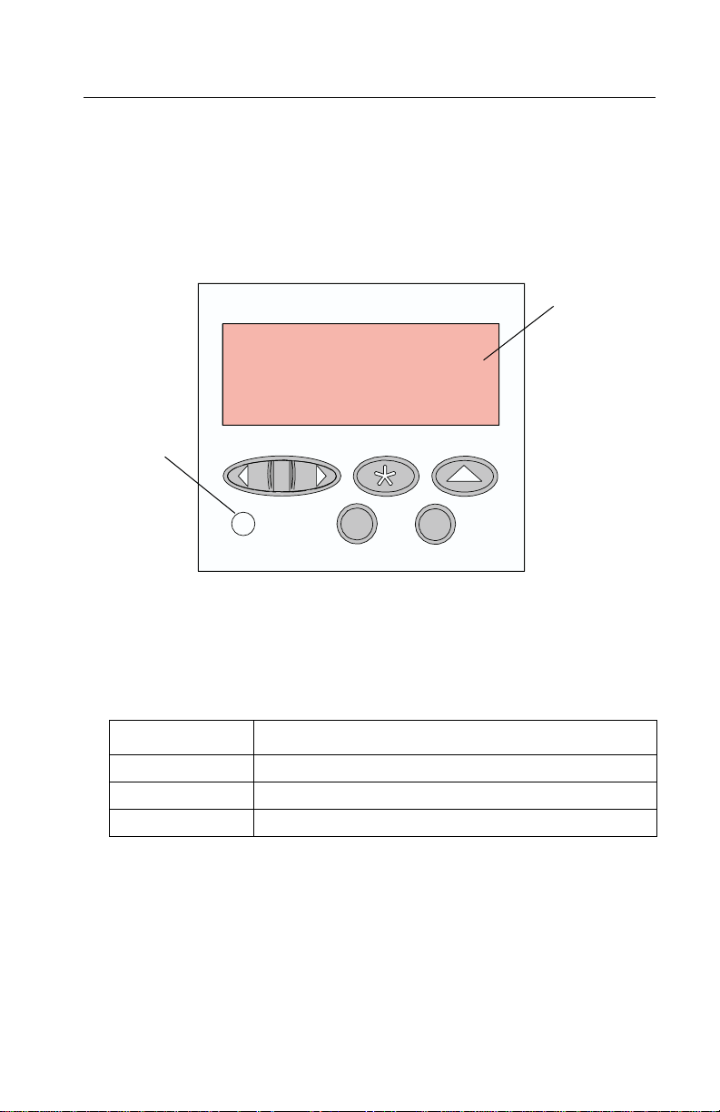
Operator Panel and Menus
Using the Operator Panel
The operator panel, on the front right side of your printer, has a
2-line by 16-character liquid crystal display (LCD), five buttons, and
one indicator light.
Operator Panel
Display
Printer
Indicator Light
Printer Indicator Light
The printer indicator light gives information about the status of your
printer.
Light State Meaning
Onsolid PoweredOnandintheReady state
Flashing Powered On and Busy
Off Unplugged from the power source
General Information 1-3
Page 16

4080-001
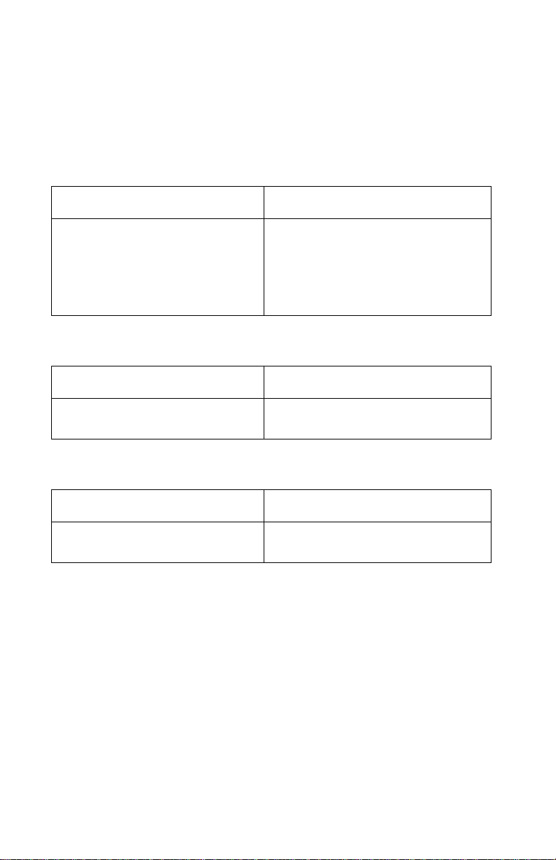
Operator Panel Buttons
Use the five operator panel buttons to open a menu, scroll through a
list of values, change printer settings, and respond to printer
messages. The following table describes the functions of each
button.
Note: Buttons act upon the information that displays on the second
line of the operator panel.
Button Function
Go Press the Go button to:
• Return the printer to the Ready state if the printer is in an
offline situation (Ready message does not appear on the
display).
• Exit printer menus displayed on the operator panel.
• Clear operator panel error messages.
If you h ave changed printer settings from the operator panel
menus, press Go before sending a job to print. The printer must
display Ready for jobs to print.
Menu>
and
<Menu
Each end of the button has a function.
Press the Menu> or <Menu button:
•AttheReady message, to take the printer
Ready state
•AttheBusy message, to take the printer to the JOB MENU.
• When the printer is offline:
-PressMenu> to go to the next item in the menus, or
-Press<Menu to go to the previous item in the menus.
• Formenu items that have numerical values, such as Copies,
press and hold Menu> to scroll forward, or <Menu to scroll
backward. Release the button when the number you want
displays.
Select Press the Select button to:
• Select the menu item shown on the second line of the display.
Depending on the type of menu, this action:
- Opens the menu and displays the first item in the menu.
- Opens the menu item and displays the default setting.
• Save the displayed menu item as the new default setting. The
printer displays the Saved message and then returns to the
menu item.
)
and enter the menus.
1-4 Service Manual
offline
(out of the
Page 17

4080-001
Button Function
Return Press the Return buttontoreturntothepreviousmenulevel.
Stop Press the Stop button:
•AttheReady,Busy,orWaiting message to temporarily stop
all activity and take the printer offline. The printer operator
panel status message changes to Not Ready.
Press Go to return the printer to the Ready state.
Printer Messages
The operator panel displays three types of messages:
• Status messages provide information about the current state of
the printer.
• Attendance messages indicate printer errors that you must
resolve.
• Service messages indicate printer failures that may require
servicing.
When the Ready status message displays, the printer is ready to
receive a print job.
While a job is printing, the Busy status message appears on the first
line of the operator panel display.
General Information 1-5
Page 18

4080-001
Operator Panel Menus
Menus make it easy for you to change printer settings. Some menus
appear only if a specific option is installed in the printer. Other menu
items may only be effective for a particular printer language. You can
select these values at any time, but they only affect printer function
when you use the specified printer language.
An asterisk (*) next to a value indicates the original factory default
setting and may vary for different countries. When you select a new
setting from the operator panel, the asterisk moves next to the
selected setting to identify it as the current user default. These
settings are active until new ones are stored or the factory defaults
are restored. Changes made from a software application or driver
override the user default settings made from the printer operator
panel.
1-6 Service Manual
Page 19

4080-001
Printing the Menu Settings Page
The menu settings page shows current settings for the menus and a
list of installed options. You can use this page to verify that the
printer options are properly installed and the printer settings are
properly set.
Note: Beforeprinting the menu settings page, make sure the Paper
Type setting for the source is Plain Paper.
To print a menu settings page:
1. Make sure the printer is plugged in and the
message appears on the display.
2. Press Menu> or <Menu to enter the menus.
3. Continue to press and release Menu> until you see
Ready status
Tests Menu.
4. Press Select.
Tests Menu appears on the first line and Print Menus is on
the second line.
5. Press Select to select
The message Printing Menu Settings appears and remains on
the operator panel display until the page prints. The printer
returns to the Ready state after the menu settings page prints.
6. If you installed options, verify that they are listed on the menu
settings page under “Installed Features.” If an option you
installed does not appear on the page, unplug the power cord
and reinstall the option.
Print Menus.
General Information 1-7
Page 20

4080-001
Changing Printer Settings
You can use the operator panel to change printer settings and
customize your printer to meet your specific needs. To select a new
value as the default setting:
1. From the
menus.
2. Continue to press and release Menu> or <Menu until the menu
you need appears on the second line of the display.
3. Press Select.
The menu opens and the first menu item in the menu appears
on the second line of the display.
4. Press Menu> or <Menu until the menu item you need appears
on the display.
5. Press Select.
An asterisk (*) appears beside the current user default setting
for that menu item.
Note: Some menu items have sub-menus. You must select another
menu (such as
6. Press Menu> or <Menu until the value you need appears on the
second line of the display.
7. Press Select.
An asterisk (*) appears beside the value to indicate that it is now
the user default setting. The display shows the new setting for
one second and then clears. The
then the previous list of menu items appears on the operator
panel display.
8. Press Return to go back to previous menus or menu items and
set new default settings.
9. Press Go to return to
want to change.
Note: User default settings remain in effect until you save new
settings or restore the factory defaults. Changes made from a
software application override the user default settings made from the
printer operator panel.
Ready state, press Menu> or <Menu to enter the
Tray1Type) before the available values display.
Saved message displays,
Ready if this is the last printer setting you
1-8 Service Manual
Page 21

4080-001
Disabling the Operator Panel Menus
To disable the menus so that changes cannot be made to the printer
default settings:
1. Unplug the printer.
2. While pressing Go and Stop,plugintheprinter.
3. Release the buttons when
When the printer self test completes, the
message appears. If you press
Menus Disabled message displays.
Performing Self Test displays.
Ready status
Menu> or <Menu,the
General Information 1-9
Page 22

4080-001
1-10 Service Manual
Page 23

4080-001
2. Diagnostic Information
Use the error indicator table, symptom tables, service checks, and
diagnostic aids to determine the printer failure.
Start
Service error indications are displayed on the operator panel. If your
printer displays an error indication, locate the error number in the
“Error Indicator Table” on page 2-2 and take the indicated action.
Unplug the printer to clear the error indicator.
Diagnostic Information 2-1
Page 24

4080-001
Error Indicator Table
Error Symptom Action
900 RIP software Refer to the “Controller Board
Service Check” on page 2-9.
902 Engine error:
065 Address error
127 - 223 Software
detection error
910
930
931
939
941 RIP code - CRC Refer to the “Controller Board
943 RIP font version Replace Font SIMM.
944
945
946
Carrier stall
Printhead error
Incomplete print
RIP - engine
communication
Processor failure
ASIC failure
SRAM failure
Replace the engine board, refer
to the “Engine Board
Removal” on page 4-22.
Refer to the “Transport
Service Check” on page 2-24.
Checkthecontrollerboard cable
connections. If the connections
are good, replace the controller
board, refer to the “Controller
Board Service Check” on
page 2-9.
If the problem remains, replace
the engine board, refer to the
“Engine Board Removal” on
page 4-22.
Note: The controller software
can cause a 939 error.
Service Check” on page 2-9.
Refer to the “Controller Board
Removal” on page 4-20.
947 Engine board Replace the engine board, refer
to the “Engine Board
Removal” on page 4-22.
953
954
960
NVRAM chip failure
NVRAM CRC failure
Controller Board DRAM
defective
Replace the controller board,
refer to the “Controller Board
Removal” on page 4-20.
2-2 Service Manual
Page 25

4080-001
Error Symptom Action
961 DRAM in (J6) is bad Replacethememory SIMM card
in (J6).
975 Unrecognized network card Ifthe incorrect card is installed,
replace the card.
976
977
978
979
Unrecoverablesoftware
error in network card
Communication error with
network card
Network card checksum
error
Flash/Network card error
Go to the “Options Service
Check” on page 2-13.
If the problem remains, replace
the controller card.
Replace network card.
Diagnostic Information 2-3
Page 26

4080-001
Power-On Self Test (POST) Sequence
Plug the printer in and check for a correct POST operation by
observing the following:
1. The operator panel displays one row of rectangles followed by
two rows of diamonds.
2. The printer indicator (green light) comes on.
3. Performing Self Test is shown on the operator panel display
and then turns off.
4. The carrier moves to the center of the frame and returns to the
maintenance station.
5. The paper feed motor turns.
6. The printer indicator light turns off and then back on.
7. Ready is displayed indicating that POST is complete.
If your pr inter completes POST with no errors, go to the “Symptom
Tables” on page 2-6, locate the symptom and take the indicated
action.
If your pr inter does not complete POST, locate the symptom in the
following table and take the indicated action.
2-4 Service Manual
Page 27

4080-001
Post Symptom Table
Symptom Action
Blank display, carrier moves,
paperfeed motor turns
All diamonds on display Go to the “Operator Panel (LCD)
Performing Self Test
remainsondisplay,nomotorsturn
Paper feed motor does not turn Go to the “Paper Feed Service
Transport motor does not turn Go to the “Transport Service
Carrier drives into left side frame Go to the “Transport Service
Printer indicator light does not light,
or remains on
POST incomplete, printer indicator
light on, no motors turn and
Performing Self Test is displayed
Printer inoperable Go to the “Power Service Check” on
Go to the “Operator Panel (LCD)
Display Service Check” on
page 2-12.
Display Service Check” on
page 2-12.
Go to the “Power Service Check” on
page 2-19.
Check” on page 2-15.
Check” on page 2-24.
Check” on page 2-24.
Go to the “Operator Panel (LCD)
Display Service Check” on
page 2-12.
Go to the “Power Service Check” on
page 2-19.
page 2-19.
Performing Self Test
remains on display, transport and
paperfeed motors turn
Replace in the following order:
• Code SIMM (if installed)
• Controller board
Diagnostic Information 2-5
Page 28
4080-001
Symptom Tables
Locate the symptom in the following tables and take the appropriate
action.
Carrier Transport Problems
Symptom Action
• No carrier movement
• Slow carrier movement
• Carrier stops
• Carrier strikes left side frame
Go to the “Transport Service
Check” on page 2-24.
Go to the “Transport Service Check
II” on page 2-25.
Communications Problems
Symptom Action
Printer not communicating with
host computer
Go to the “Parallel Wrap Test” on
page 3-6.
Maintenance Station Problems
Symptom Action
• Fails to cap the printhead
• Fails to clean the printhead
Go to the “Maintenance Station
Service Check” on page 2-10.
2-6 Service Manual
Page 29

4080-001
Operator Panel Problems
Symptom Action
Printer indicator light does not:
•Turnon
•Flash
•Turnoff
• All diamonds
One or two pels missing Replace the operator panel assembly.
Only one button inoperative Replace the operator panel assembly.
More than one button inoperative Go to the “Operator Panel (Buttons)
All diamonds on display Go to the “Operator Panel (LCD)
Go to the “Operator Panel (LCD)
Display Service Check” on
page 2-12.
ServiceCheck”onpage2-11.
Display Service Check” on
page 2-12.
Paper Feed Problems
Symptom Action
Paper fails to stop at first print line
• Fails to pick paper
• Picks more than one sheet of
paper
• Picks paper but fails to feed
• Paper jams
• Paper fails to exit
• Noisy paper feed
• Paper skews
Go to the “Paper Feed Service
Check” on page 2-15.
Paper does not feed, motor does
not turn
Paper does not feed motor
attempts to turn
Go to the Paper Feed Service Check
“Paper does not feed - paper feed
motor does not turn” on page 2-16.
Go to the Paper Feed Service Check
“Paper does not feed - paper feed
motor turns in only one direction”
on page 2-17.
Diagnostic Information 2-7
Page 30

4080-001
Power Problems
Symptom Action
Printerinoperable Gotothe“Power Service Check” on
page 2-19.
Print Quality Problems
Symptom Action
• Voids in characters
•Lightprint
• Prints off the page
•Fuzzyprint
• Carrier moves but does not print
• Printhead drying prematurely
• Vertical alignment off
• Excessive ink flow (Flooding)
• Horizontal banding
• Ink smearing
• Vertical streaks on paper
• Print lines crowded
Go to the “Print Quality Service
Check” on page 2-21.
Go to the “Paper Feed Service
Check” on page 2-15.
2-8 Service Manual
Page 31

4080-001
Service Checks
Controller Board Service Check
FRU Action
1 Code SIMM Some printers may contain a code SIMM located
in the option card(s) (J6) on the controller board. If
a SIMM is present, replace the code SIMM, go to
the “Code or Flash SIMM Removal” on
page 4-19. If the problem remains, continue to
step 2.
2 Controller Board If the printer does not contain a code SIMM in the
option card(s) (J6), replace the controller board,
go to the “Controller Board Removal” on
page 4-20.
Encoder Card / Strip Service Check
Note: Be sure the printer is unplugged from the AC outlet before
performing this service check.
Disconnect the transport motor (CN5) from the engine board. Move
the carrier to where it is parked over the maintenance station, turn
the printer on and after Performing Self Test appears on the display,
wait approximately five seconds and move the carrier to the center
of the printer and back to the maintenance station. Ready should
appear on the display. If not, check the connection at the encoder
card (CN1) and retest. If the problem remains, replace the encoder
card, refer to the “Encoder / Thermistor Card Removal” on
page 4-21. You may have to perform this check several times.
Diagnostic Information 2-9
Page 32

4080-001
End of Forms (EOF) Service Check
Before turning the printer o n, remove any paper from the input tray
and insert one sheet of paper into the manual paper tray slot. If
paper feeds through the machine when the printer is turned on, the
sensor is functioning properly. If paper fails to feed, check the end of
forms sensor flag for correct operation. If the operation is bad,
replace the flag. If the operation is good, replace the engine board,
refer to the “Engine Board Removal” on page 4-22.
Maintenance Station Service Check
The maintenance station has two functions:
1. Cleans the printhead nozzles during the print operation.
2. Seals the printhead when it is not being used to prevent the
nozzles from drying.
FRU Action
1 Maintenance
Station Assembly
2 Wiper A worn wiper can cause degraded print quality just
3 Cap A worn cap can cause the printhead nozzles to
As the carrier moves to the right over the
maintenance station, a slot on the bottom of the
carrier engages a tab on the sled of the
maintenance station causing the caps to rise and
seal the printheads. Carrier movement to the left
will uncap the printheads. The wipers clean the
printhead nozzles as the carrier leaves the
maintenance station. The wipers clean the
printheads only when the carrier is moving to the
left. There should be no wiping action of the
printhead nozzles when the carrier is moving to
the right. After the cleaning operation is complete,
a tab on the maintenance station engages a tab
on the carrier, causing the w ipers to lower.
Check the maintenance station for worn or broken
parts.
after a maintenance cleaning. Check for loose or
worn wiper.
dry and clog. Check for loose or worn cap.
2-10 Service Manual
Page 33

4080-001
Noisy Paper Feed Motor Service Check
FRU Action
1 Paper Feed Motor Check the following motor pins for approximately
12.5 ohms:
(CN6-1) and (CN6-2)
(CN6-3) and (CN6-4)
If incorrect, replace the paper feed motor, refer to
the “Paper Feed Motor Removal” on page 4-16.
2 Gears Check the gears for proper alignment, chipped
teeth, loose motor, missing gear clip or worn
gears.
Operator Panel (Buttons) Service Check
Note: Perform the “Button Test” on page 3-4, before continuing
this service check.
FRU Action
1 Operator Panel
Assembly
2 Controller Board
Operator Panel
Assembly
If any button fails the button test, replace the
operator panel assembly.
Be sure the voltage at (JT6-2) measures +5 V dc.
If the voltage is incorrect, replace the controller
board. If the voltage is correct, check the
continuity of the operator panel cable. Replace the
operator panel cable if continuity is incorrect. If
correct, replace the operator panel assembly.
Diagnostic Information 2-11
Page 34

4080-001
Operator Panel (LCD) Display Service Check
Note: Be sure the operator cable is properly installed at the
controller board (JT6) and at the operator panel. Check the
continuity of the cable and replace if necessary.
Operator panel display blank - printer indicator light OFF,
paperfeed motor turns, carrier moves.
FRU Action
1 Controller Board Verify the voltage at (JT6-2) on the controller
board is approximately +5 V dc. If incorrect,
replace the controller board. If correct, go to step
2.
2 Operator Panel
Assembly
Verify that the resistance between (JT6-4) and
ground on the controller board is approximately 0
ohms. If incorrect, replace the controller board. If
correct, replace the operator panel assembly.
Operator panel display blank - printer indicator light ON.
FRU Action
1 Controller Board
Operator Panel
Assembly
Verify that the resistance between (JT6-4) and
ground on the controller board is approximately 0
ohms. If incorrect, replace the controller board. If
correct, replace the operator panel assembly.
2-12 Service Manual
Page 35

4080-001
Options Service Check
Flash Memory Option(s)
Run a copy of the test page and check to see if the option you are
checking is listed. The printer does not recognize the option being
installed if the option is not listed. Check to make sure that the
Memory SIMM is installed correctly and is not broken or damaged. If
the Memory SIMM is correctly installed, and not broken or damaged,
then run the “Flash Test”on page 3-10. If the test fails, replace the
flash SIMM. If the problem continues, replace the controller board,
refer to the “Controller Board Removal” on page 4-20.
DRAM Memory Option(s)
This service check is the same as the flash memory option service
check with the following exception:
Run the “DRAM Memory Test” on page 3-5 from the menu if the
DRAM Memor y SIMM is correctly installed and not broken or
damaged. If the test fails, replace the DRAM SIMM, refer to the
“Memory (SIMM) Card Cover Removal” on page 4-7.Ifthe
problem continues, replace the controller board, refer to the
“Controller Board Removal” on page 4-20.
Hard Disk Option
Be sure the hard disk and the hard disk adapter board are correctly
installed. Run the “Quick Disk Test” on page 3-8 from the Device
Test on the Diagnostic Menu when a problem is suspected either
with the hard disk adapter board or with the hard disk.
Note: The Quick Disk Test is a non-destructive test and indicates
Pass or Fail. If the test fails, replace the hard disk, refer to the
“Option Card(s) Removal” on page 4-25.Ifaproblemstillexists,
replace the controller board, refer to the “Controller Board
Removal” on page 4-20.
The “Disk Test/Clean” on page 3-9 is used to help restore the disk
if the data is corrupted and unusable. This test is divided into a
cleaning and a verifying section.
Note: The test can be very lengthy and leaves the hard disk
unformatted. The servicer or user must reformat the disk using the
Diagnostic Information 2-13
Page 36

4080-001
Format Disk Menu operation. This is a destructive test, as the data
on the disk is destroyed and should not be performed on a known
good disk.
Network Card Option
Error Code 976 - Network Card
A 976 error code indicates an unrecoverable software error in
network card. Verify that the network card is correctly installed in the
controller board socket, and is properly grounded. If you find no
problem, contact your next level of support before replacing the
network card.
Error Code 977 - Network Card
A 977 error displays when the RIP software detects that a network
card is installed, but cannot establish communications with the
network card. Replace the networ k card, refer to “Option Card(s)
Removal” on page 4-25. If the problem remains, replace the
controller board, refer to “Controller Board Removal” on
page 4-20.
2-14 Service Manual
Page 37

4080-001
Paper Feed Service Check
Note: Be sure the printer is unplugged from the AC outlet before
performing this service check.
Perform the following, if you are experiencing a paper jam:
• Check the entire paper path for obstructions.
• Be sure the input tray contains not more than 150 sheets of
paper and the manual tray not more than 100.
• Be sure the correct type of paper is being used.
• Check for static in the paper.
• Ensure the correct position of the left paper adjuster guide lifter
assembly.
• Check for skew by performing the “Test Page (Quick Test)”on
page 3-15.
FRU Action
1 Gears Check for binds in the gear train and paper feed
2 Paper Path Perform the “Paper Path Service Check” on
mechanism by rotating the large feed roll by hand.
Check all gears for correct installation and signs of
wear or damage. If there is a bind, isolate it by
removing one of the small idler gears on the inside
of the left side frame. Replace any worn or binding
gears or rollers.
page 2-18.
Diagnostic Information 2-15
Page 38

4080-001
Paper does not feed - paper feed motor does not turn
Note: A noisy or chattering motor or a motor that fails to turn can be
caused by:
• A defective motor
• A bind in the paper feed mechanism
• Defective gears
• Defective engine board
• Defective power supply (+30 V dc)
FRU Action
1 Engine Board With (CN6) connected and power on, check the
voltage between Pins 1,2,3,4 and ground. The
voltage should measure between +15 V dc and
+32 V dc when paper is feeding. If the voltage is
correct, replace the engine board.
2 Paper Feed Motor Check the motor pins between (CN6-1) and
(CN6-2) for approximately 12.5 ohms. Also check
(CN6-3) and (CN6-4) for approximately 12.5
ohms. If incorrect, r eplace the paper feed motor
assembly. If correct, check the continuity between
each motor pin on the motor connector and the
motor case. If continuity exists, replace the paper
feed motor assembly. If the symptom remains, go
to step 3.
Note: If a short exists in the paper feed motor,
damage to the system board drivers and power
supply may occur.
3 Power Supply Disconnect the AC line cord. Disconnect (J2-6)
from the controller board and verify the voltage on
the cable is approximately +30 V dc. If incorrect,
replace the power supply.
4 Engine Board Check continuity between (J2-6) on the controller
board and (C10-36) on the system board. If
correct, replace the engine board. If correct, go to
step 5.
5 Controller Board
Cable
Check the continuity of the controller board cable.
If incorrect, replace the cable. If correct, replace
the controller board.
2-16 Service Manual
Page 39

4080-001
Paper does not feed - paper feed motor turns
Note: Anoisy or chattering motor or a motor that fails to turn can be
caused by:
• A defective motor
• A bind in the paper feed mechanism
• Defective gears
• Defective engine board
FRU Action
1 Gear Box Check the clutch lever for obstructions and the
gear box for binds and wear. Replace worn or
binding gears.
2 Gears Check for binds in the gear train and paper feed
mechanism by rotating the large feed roll by hand.
If you notice a bind, isolate it by removing one of
the small idler gears on the inside of the left side
frame. Replace any worn or binding gears or
rollers.
3 Large Feed Roller Be sure that the large feed roller is clean.
4 Paper Lifters Check the paper lifters, pads and paper tray for
proper positioning.
5 Paper Adjuster Check for correct position of the left paper adjuster
guide lifter assembly.
Paper does not feed - paper feed motor turns in only one direction
• When paper is fed from the input tray, the paper feed motor
rotates counterclockwise actuating the paper lifters, followed by
a clockwise rotation.
• When feeding from the manual tray, the paper feed motor
rotates in only one direction. If,when paper is fed from the input
tray and the motor turns in one direction only, replace the
engine board.
Diagnostic Information 2-17
Page 40

4080-001
Paper Path Service Check
Examine the printer for the following before you begin this service
check:
• Check the entire paper path for obstructions.
• Be sure the paper guides are not worn or broken, and the paper
is positioned properly.
• Be sure the correct type of paper is being used.
• Be sure the printer is installed on a flat surface.
FRU Action
1 Large and Small
Feed Rollers
2 Small Feed Roller
Springs
3ExitRoller
Star Rollers
4 Input / Output
Tray
5End-of-Forms
Flag & Spring
Check for wear and binds.
Check for damage.
Check for wear and binds.
Check the following for wear or damage:
• Paper lifters assemblies
• All parts inside the left and right edge guides.
Check for binds or damage.
2-18 Service Manual
Page 41

4080-001
Power Service Check
Dead Machine
Note: Remove paper from printer prior to performing the dead
machine ser vice check. Obser ve all necessary ESD precautions
when removing and handling the controller board, engine board or
any of the installed option cards or assemblies.
FRU Action
1 AC Outlet Check the AC outlet for correct line voltage. If
incorrect, inform the customer.
2 Power Line Cord Check the power line cord for damage. Check
the continuity of the line cord and replace if
necessary.
3 Power Supply
Fuse (F1)
4 Power Supply If fuse (F1) continues to fail, replace the fuse
Verify the voltage between (J2-1) on the power
supply connector and ground is approximately
+5 V dc. If incorrect, check fuse F1. If the fuse
is defective, replace the fuse and re-verify the
voltage at (J2-1).
If incorrect, continue to step 4.
Note: Disconnect the line cord prior to
checking fuse F1.
and disconnect the (J2) connector from the
controller board before applying power.
Check for approximately +5 V dc between
connector (J2-1) and ground. If incorrect
replace the power supply.Ifcorrect, disconnect
all connectors to the controller board except
(J2).
Check for approximately +5 V dc between
connector (J2-1) and ground. If incorrect,
replace the controller board.
Reconnect the (J1) engine board connector
and disconnect all cables connected to the
engine board. Check for approximately +5 V dc
between connector (J2-1) and ground. If
incorrect, replace the engine board. If correct,
reconnect one cable at a time checking the
voltage at (J2) each time until the problem is
found.
Diagnostic Information 2-19
Page 42

4080-001
POST incomplete , printer indicator light on, Performing Self Test is
displayed and no motors turn.
Note: Excessive ink may be present in the maintenance station
caps.
FRU Action
1 Power Supply Check for approximately +30 V dc at (J2-6) on the
2 Transport Motor
Engine Board
3 Controller Board
Cable
controller board.
Check for approximately +30 V dc at (CN5-1) on
theengineboard.Ifcorrect,disconnectthemotor
and check the resistance between (CN5-1) and
(CN5-2), which should measure between 10.5 -
12.5 ohms. If the resistance is incorrect, replace
the motor. If the resistance is correct, check for
approximately +30 V dc on the transistor tab Q17
on the engine board. If the voltage is incorrect,
replace the engine board. If the voltage is correct,
go to step 3.
Check the continuity of the controller board cable.
If incorrect, replace the cable. If correct, replace
the engine board. if the problem remains, replace
the controller board.
2-20 Service Manual
Page 43

4080-001
Print Quality Service Check
Note: Before troubleshooting any print quality problem, be sure the
cartridge is in good condition. Set print quality to normal and be sure
the correct paper type is selected in the paper menu. Set the color
menu to Vivid and select black and white if checking B/W print
quality.
FRU Action
1 Printhead Carrier
Assembly
Re-seat the printhead cables in the engine board
and check the following parts for wear or damage:
• Print Cartridge Latch
• Latch Spring
•Carrier
Diagnostic Information 2-21
Page 44

4080-001
FRU Action
2EngineBoard
Printhead Cable
Rubber Backer
Perform the Clean Heads from the diagnostic
mode. Look for a break in the diagonal line of the
test pattern. A broken line indicates one or more
print nozzles are not working. Run the test again
to verify the failure. If there are even breaks in the
diagonal line similar to the patter n shown below,
replace the engine board.
If there is a single break or random breaks in the
diagonal line check the following:
• Check the gold-plated contacts, on the end of
the cable that connect to the carrier, for dirt and
wear. Use only a clean dry cloth to clean the
contacts. Also check the cable for damage. You
mayneedtoremovethecablefromthecarrier
to inspect it.
• A worn rubber backer results in poor contact
between the printhead cable and the print
cartridge. Check the rubber backer for wear.
• Referto the test page. The temperature value is
Celsius.
Note: Printing slows to prevent overheating and
excessiveink flow,when the temperature is above
the normal operating range, or when printing
complex graphics.
The normal operating temperature range is
60 to 90° F (16 to 32° C). If the printer is operating
in a warm environment, >104° F (40° C),
excessive ink may flow from the cartridge. The
operating temperature can be found by performing
the “Cleaning the Printheads” on page 3-2.
3 Maintenance
Station
2-22 Service Manual
Intermittent nozzle failures can be caused by worn
parts in the maintenance station. Perform the
“Maintenance Station Service Check” on
page 2-10, then return to this check.
Page 45

4080-001
FRU Action
4 Paper Feed Ink smudging and smearing can be caused by
paper problems or problems in the paper feed
area.
Check the following:
• Correct type of paper is being used.
• Paper for curl or wrinkles.
• Feed rollers for wear, dirt, or looseness.
• Gears for wear or binds.
• Paper path for obstructions.
5 Transport Blurred print and voids can be caused by
problems in the transport area. Check the
following:
• Transport belt for wear and full engagement into
the carrier grip.
• Carrier guide rod for wear or dirt.
• Carrier to carrier frame engagement should be
lubricated with grease P/N 99A0394.
Lubricate the carrier guide rod and carrier frame
on both sides where the two surfaces ride on
the frame.
• Idler pulley parts for wear, damage, or
looseness.
• Encoder strip for wear or dirt.
6 Alignment Characters having uneven or jagged edges, or
uneven vertical, horizontal, bidirectional (black or
color) alignment can be checked by entering
Diagnostics Mode and selecting
Align Cartridges.
Diagnostic Information 2-23
Page 46

4080-001
Transport Service Check
Note: If the carrier strikes the left side frame and continues to drive
into the frame, refer to the “Transport Service Check II” on
page 2-25.
FRU Action
1 Transport Motor Check the motor for binds, or loose motor pulley.
Disconnect the transport motor (J5) from the
engine board. Check for approximately 12 ohms
between pins 1 and 2 on the motor cable. If the
reading is incorrect, replace the motor.
Check for motor pins shorted to the motor
housing. If you find a pin shorted to the housing,
replace the motor. If the failure remains, replace
theengineboard.
2 Engine Board Disconnect (CN5) from the engine board and
check for approximately +30 V dc between
(CN5-1) and ground. If incorrect, replace the
engine board.
3 Carrier Guide
Rod
4 Carrier Belt
Idler Pulley Parts
Carrier Frame
5 Encoder Strip
Encoder Card
6 Printhead Cable Be sure all connectors are fully seated. Check the
7 Maintenance
Station
Clean the carrier rod.
Note: Lubricate the rod and the carrier rod bearing
surface.
Check for worn, loose or broken parts. Check for
obstructions blocking carrier movement.
Check the encoder strip for wear, dirt and grease.
Go to the “Encoder Card / Strip Service Check”
on page 2-9.
cables for damage.
A problem with the maintenance station can cause
carrier movement problems at the right margin. Go
to the “Maintenance Station Service Check” on
page 2-10.
2-24 Service Manual
Page 47

4080-001
Transport Service Check II
Carrier strikes left side frame and continues to drive into frame
Note: Be sure the printer is unplugged from the AC outlet before
performing this service check.
• Check the carrier cable connection at (CN2) and encoder
connection at (CN1) on the engine board.
• If the problem remains, disconnect the transport motor (CN5)
connection from the engine board, turn the printer on and wait
until “Performing Self Test” appears on the display. Manually
move the carrier to the center location and then back to where it
is parked over the maintenance station. After several seconds,
“Ready” should appear on the display. If not, check the
connection at the encoder card (CN1) and retest. If the problem
remains, replace the encoder card.
Tray 2 Service Check
Note: Be sure the tray 2 is properly installed and loaded.
Paper does not feed.
FRU Action
1 Drive Gear Check for binds and any obstructions in the paper
path.
2 Tray 2 Drive Gear Be sure the drive gear clips are properly installed.
Be sure the tray 2 drive gear and left side frame
drive gear are properly meshed together.
3 Tray 2 Sensor Disconnect(CN11) and check the continuity of the
tray 2 sensor switch. If the switch is defective,
replace the switch. If the switch is not defective,
replace the system board.
Diagnostic Information 2-25
Page 48

4080-001
Paper does not feed, but gears turn
FRU Action
1 Drive Belt Check for binds and any obstructions in the paper
path. Be sure the tray 2 and drive gear are
properly installed. Be sure the drive belt is
properly installed.
2 Autocompensator Check the autocompensator and clutch spring. Be
sure the roller on the autocompensator turns when
paper is fed. If the roller fails to turn, be sure the
drive belt is installed properly. If the problem
remains, replace the paper tray 2.
.
Paper Tray 2 is noisy when feeding paper.
FRU Action
1 Gears Be sure the tray 2, drive gear and clip are installed
properly.
2 Tray 2 Drive Gear Be sure the drive gear clips are properly installed.
Be sure the tray 2 drive gear and left side frame
drive gear are properly meshed together.
2-26 Service Manual
Page 49

4080-001
User Error Messages
Message Explanation
30 Cartridges Missing:
•Color
•Black
•Photo
38 Memory Full Press Go to clear the message and continue
51 Defective Flash Press Go to clear the message and continue
Press the Go button to clear the error. At this
point the Supplies status appears on the
display and the cartridge missing shows in the
supplies menus. This remains until the user
accesses the Tests Menu to install a cartridge
and fill the empty slots. If a print job is sent
while in this state, it may result in poor print
quality since the job most likely requires the
missing cartridge.
processing the job. Some data will be lost. You
must allow additional memory to complete your
print job by:
• Deleting fonts, macros and other data in
RAM.
• Simplifying your print job.
• Installing additional memory.
Press Menu> or Menu< to access the reset
function in the Busy/Waiting Menu group.
Menu Lockout does not prevent access to the
Busy/Waiting Menu group. The menu buttons
are not active when Reset Control is Off.
processing the job. All downloaded fonts and
macros not written to flash will be deleted.
Press Menu> or Menu< to access the reset
function in the Busy/Waiting Menu group.
Menu Lockout does not prevent access to the
Busy/Waiting Menu group. The menu buttons
are not active when Reset Control is Off.
53 Unformatted Flash Press Go to clear the message. The flash will
be marked as bad and normal operation will
continue. Flash operations will not be allowed
until the flash is formatted.
54 Serial Option x Error This error indicates that the serial port has
been improperly set.
Diagnostic Information 2-27
Page 50

4080-001
Message Explanation
54 Parallel Error This error occurs when a IEEE 1284 protocol
error has been detected on the parallel host
interface, or due to a faulty cable.
Once a host interface error has been displayed
for the first time, reporting of further host
interface errors for the associated port is
suppressed until the interface parameters are
changed, or the printer is powered off.
Press Go to clear the message and continue
processing the print job. The job may not print
correctly. Verify that the correct cable is used. If
a serial error has occurred, be sure the serial
interfaceparameters(protocol, baud, parity and
data bits) are set correctly on the printer and
the host computer. If a parallel error has
occurred, check the cable connection between
the host and printer.
Press Menu> or Menu< to access the reset
function in the Busy/Waiting Menu group.
Menu Lockout does not prevent access to the
Busy/Waiting Menu group. The menu buttons
are not active when Reset Control is Off.
Press and hold Select and then press Return to
determine the exact cause of host interface
error.
If a serial error has occurred, a 16-bit error
code displays in hexadecimal on the second
line of the LCD. If bit 15 is on, a framing error
has occurred. If bit 14 is on, an overrun error
has occurred. If bit 13 is on, a parity error has
occurred.
2-28 Service Manual
Page 51

4080-001
Message Explanation
56 Serial x Port Disabled This error occurs when data is sent to the
printer across the optional serial port x
(where x=1, 2, or 3), but the port is disabled.
Once the error displays the first time, reporting
of further errors is suppressed until the menus
are entered, or the printer is reset.
Press Go to clear the message. The printer
discards any data received on the serial port.
Enable the serial port.
Press Menu> or Menu< to access the reset
function in the Busy/Waiting Menu group.
Note: The menu buttons are not active when
Reset Control is Off.
Note: Menu Lockout does not prevent access
to the Busy/Waiting Menu group.
56 Parallel Port Disabled Once the error has been displayed for the first
61 Defective Disk Press Go to clear the message. The disk will be
time, reporting of further error is suppressed
until the menus are entered, or the printer is
reset.
Press Go to clear the message. The printer
discards any data received on the serial port.
Enable the serial port.
Press Menu> or Menu< to access the reset
function in the Busy/Waiting Menu group.
Note: The menu buttons are not active when
Reset Control is Off.
Note: Menu Lockout does not prevent access
to the Busy/Waiting Menu group.
marked as defective and normal printer
operation continues. Disk operations are not
allowed with a defectivedisk, and the Format
Disk menu item is not shown.
Diagnostic Information 2-29
Page 52

4080-001
Message Explanation
62 Disk Full Press Go to clear the message and continue
processing the job. All downloaded fonts and
macros not written to disk are deleted.
Press Menu> or Menu< to access the reset
function in the Busy/Waiting Menu group.
Note: The menu buttons are not active when
Reset Control is Off.
Note: Menu Lockout does not prevent access
to the Busy/Waiting Menu group.
63 Unformatted Disk Press Go to clear the message. The disk will be
marked as bad and normal operation
continues. Disk operations are not allowed until
the disk is formatted.
200 Paper Jam This message indicates that a paper jam has
occurred. If the error does not clear after
cleaning the paper jam, go to the “Paper Feed
Service Check” on page 2-15.
2-30 Service Manual
Page 53

4080-001
3. Diagnostic Aids
Diagnostic Mode
To enter the Diagnostic Mode:
1. Turn the printer off.
2. Press and hold the Go and Return buttons.
3. Turn the printer on.
4. Release the buttons when Performing Self Test displays on
the operator panel.
Note: Select Exit Diagnostics to return to normal mode.
The tests display on the operator panel in the order shown:
• Print Tests
• Hardware Tests
• Printer Setup
• Error Log
• Align Cartridges
• Base Sensor Tests
• Exit Diagnostics
Diagnostic Aids 3-1
Page 54

4080-001
Aligning the Cartridges
1. Enter Diagnostics Mode.
2. Select Align Cartridges.
3. Press <MENU> to select the test.
4. Press Select
• Horizontal Align
• Vertical Align
• Bi-di Black Align
• Bi-di Color Align
5. Test (A) Alignment = XX* - The alignment can be changed by
pressing <MENU> to change the setting.
6. Press SELECT to save the setting.
7. Once any changes have been made, a test page can be printed
showing the changes by selecting Print Align Page.
8. Use the test page to check each alignment, A-D.
9. If changes are necessary repeat step 5.
Cleaning the Printheads
1. Enter Diagnostics Mode.
2. Select Hardware Test.
3. Press <MENU> to go to “Clean Heads”.
4. Press Select. The nozzle test pattern test page prints.
Paper Lifters Operation Theory
As the carrier applies pressure against the clutch lever, located in
the gear box assembly, the left and right paper lifters engage,
positioning the media into the printer. Media is then pulled through
the printer by the combination of torque action between the paper
feed motor and the large feed roller, and friction between the paper
feed motor and the media.
3-2 Service Manual
Page 55

4080-001
Error Log
Viewing the Error Log
The error log is helpful to the servicer by providing a history of
printer errors. The error log contains the 12 most recent errors. The
most recent error displays in position 1 and the oldest error displays
in position 12 (if 12 errors have occurred). If an error occurs after the
log is full, the oldest error is discarded. Identical errors in
consecutive positions in the log are entered. All 2xx and 9xx error
messages are stored in the error log.
To view the Error Log:
1. Select Display Log from the Error Log menu. The Error log
displays on 3 screens as only 4 entries display at a time.
2. To move to the next screen press Menu> to move forward or
<Menu to move backward.
3. Press Return/Stop to exit the Error Log.
Clearing the Error Log
To clear the Error Log:
1. Select Clear Log from the Error Log menu.
2. Select YES to clear the Error Log or NO to exit the Clear Log
menu. If YES is selected, the Empty Error Log displays on the
screen.
3. Press Return/Stop to exit the Clear Log menu.
Diagnostic Aids 3-3
Page 56

4080-001
Hardware Te sts
The following Hardware Tests can be selected from this menu:
• Clean Heads
• LCD Test
• Button Test
• DRAM Memory Test
• ROM Memory Test
• Parallel Wrap (if available)
• Serial Wrap (if available)
LCD Test
To run the LCD Test:
1. Select LCD Test from the Diagnostic menu.
(The LCD test continually executes the LCD display test).
2. Press Return/Stop to cancel the test.
Button Test
To run the Button Test:
1. Select Button Test from the Diagnostic menu. With no buttons
pressed several OP (Open) appear on the display.
2. Press each button one at a time and a CL (Closed) displays in
place of an OP. The proper operation of each button can be
checked.
3. Press Return/Stop to cancel the test.
3-4 Service Manual
Page 57

4080-001
DRAM Memory Test
The purpose of this test is to check the validity of DRAM, both
standard and optional. The test writes patterns of data to DRAM to
verify that each bit in memory can be set and read correctly.
To run the DRAM Memory Test:
1. Select DRAM Memory Test from the menu. The power
indicator blinks indicating the test is in progress.
2. Press Return/Stop to exit the test.
P:###### represents the number of times the memory test has
passed and finished successfully. Initially 000000 displays with the
maximum pass c ount being 999,999.
F:##### represents the of time the memory test has failed and
finished with errors. Initially 00000 displays with the maximum fail
count being 99,999.
Once the maximum pass count or fail count is reached, the test is
stopped, the power indicator is turned on solid, and the final results
display. If the test fails, the message DRAM Error, displays for
approximately 3 seconds and the failure count increases by 1.
Diagnostic Aids 3-5
Page 58

4080-001
ROM Memory Test
The ROM Memory Test is used to check the validity of the RIP code
and fonts.
To run the ROM Memory Test:
1. Select ROM Memory Test from the menu. P and F represent
the same numbers for DRAM. The power indicator blinks
indicating the test is in process. The test runs continuously.
2. Press Return/Stop to exit the test.
Each time the test finishes, the screen updates with the result. If the
test passes, the Pass Count increases by 1, however if the test fails,
one of the following messages displays for approximately 3 seconds:
ROM Checksum Error, ROM Burst Read Error
Once the maximum pass count or fail count is reached, the test
stops with the power indicator on solid. The final results display on
the screen.
Parallel Wrap Test
This test is used with a wrap plug to check operation of the parallel
port hardware. Each parallel signal is tested.
To run the Parallel Wrap Test:
1. Disconnect the parallel interface cable and install the wrap plug
(P/N 1319128).
2. Select the Parallel Wrap Test from the menu.The pr inter
indicator light flashes indicating the test is in progress. The test
runs continuously until canceled.
Each time the test finishes, the screen updates. If the test passes,
the Pass Count increases by 1, however if the test fails, an error
message displays for approximately 3 seconds. Once the maximum
count is reached the test stops. The powerindicator shows solid and
the final results display.
3. Press Return/Stop to exit the test.
3-6 Service Manual
Page 59

4080-001
Serial Wrap Test
This test is used to check the operation of the Serial Port Hardware
using a wrap plug. Each signal is tested.
To run the Serial Wrap Test:
1. Disconnect the serial interface cable and install the wrap plug.
2. Select the Serial Wrap Test from the menu. The power
indicator blinks indicating the test is running.
3. This test runs continuously unless canceled by pressing
Return/Stop.
Each time the test finishes, the screen updates with the result. If the
test passes, the Pass Count increases by 1, however if the test fails,
a message displays for approximately 3 seconds and the Fail Count
increases by 1. Once the maximum count is reached the test stops.
The power indicator shows solid and the final results display.
4. Press Return/Stop to exit the test.
Diagnostic Aids 3-7
Page 60

4080-001
Device Tests
Hex Trace
Hex Trace can be used to help diagnose print job problems.
To invoke the Hex Trace:
1. Select Hex Trace from the Tests Menu.
2. Send a print job to the printer. (The document should print in
both hexadecimal and character formats.)
3. Select Reset Printer from the Tests Menu or unplug the printer,
to exit Hex Trace.
Quick Disk Test
This test performs a non-destructive read/write on one block per
track on the disk. The test reads one block on each track, saves the
data, and proceeds to write and read four test patterns to the bytes
in the block. If the block is good, the saved data is written back to the
disk.
To run the Quick Disk Test:
1. Select the Quick Disk Test from the Device Tests menu.
• The power indicator blinks while the test is in progress.
• Quick D isk Test/Test Passed message displays if the test
passes and the power indicator turns on solid.
• Quick Disk Test/Test Failed message displays if the test
failed and the power indicator turns on solid.
2. Press Go, Return,orStop to return to the Device Tests menu.
3-8 Service Manual
Page 61

4080-001
Disk Test/Clean
WARNING: This test destroys all data on the disk and should not be
attempted on a good disk. Also note that this test may run
approximately 1 1/2 hours depending on the disk size.
To run the Disk Test/Clean Test:
1. Select Disk Test/Clean from the Device Tests menu.
– Files will be lost/Go or Stop? message displays to warn
the user that all contents on the disk will be lost.
2. To exit the test immediately and return to the Device Tests
menu, press Return/Stop. To continue with the test, press Go.
– If go is selected, Disk Test/Clean/BAD:000000 00%
message displays. The screen updates periodically
indicating the percentage of test completed and the number
of bad blocks found.
3. The power indicator blinks dur ing the test. The test can be
canceled anytime during the test by pressing Return/Stop.
– Once the test is complete, the power indicator shows solid
and a message displays.
– XXXX Bad Blocks/YYYYYY Usable message displays if
fewer than 2000 bad blocks are detected. XXXX indicates
the number of bad blocks and YYYYYY indicates the
number of usable blocks.
– XXXX Bad Blocks/Replace Disk message displays if more
than 2000 bad blocks are detected. The disk cannot be
recovered because too many bad blocks exist on the disk.
4. Press Go or Return/Stop to return to the Device Tests menu.
Diagnostic Aids 3-9
Page 62

4080-001
Flash Test
This test causes the file system to write and read data on the flash to
test the flash.
WARNING: This test destroys all data on the flash because the
flash is reformatted at the end of the test.
To run the Flash Test:
1. Select Flash Test from the Device Tests menu.
– The power indicator blinks while the test is running.
– Flash Test/Test Passed message displays if the test passes
and the power indicator shows solid.
– Flash Test/Test Failed message displays if the test fails and
the power indicator shows solid.
2. Press Go or Return/Stop to return to the Device Tests menu.
3-10 Service Manual
Page 63

4080-001
Printer Setup
Setting the Page Count
This lets the servicer change the page count from the diagnostic
menu. This is used whenever the engine board is replaced because
this board contains the printer's NVRAM Memory where the page
count is stored.
To set the Page Count:
1. Select Printer Setup from the Diagnostic menu.
2. Select Page Count from the Diagnostic menu.
a. The current page count displays.
b. The leftmost digit blinks, indicating it is the first digit to be
changed.
3. Press either Menu> or <Menu until the value you want displays.
4. Press Select to move to the next digit, press Menu> or <Menu
until the value you want displays. Continue with each digit until
you set the page count. You can skip any digit by pressing
Select.
5. Press Select to save the new page count in NVRAM.
6. Press Return/Stop to exit.
Viewing the Permanent Page Count
The Permanent Page Count can only be viewed and cannot be
changed.
To view the Permanent Page Count:
1. Select Permanent Page Count from the menu.
2. Press Return/Stop to exit.
Diagnostic Aids 3-11
Page 64

4080-001
Restore Factory Defaults
To restore each of the printer settings contained in the Setup menu
to their factory default value select Restore from the menu. To exit
the menu without restoring the settings to the factory default values,
select Do Not Restore. Sometimes this is used to help correct print
quality problems.
Print Tests
The purpose of the diagnostic Print Tests is to verify that the printer
can print on media from each of the installed input options. Each of
the installed options is listed in the following order in the menu:
• Tray 1(input tray)
• Optional Paper Tray 2 (if installed)
• Manual Tray
For each input source selected you have the following choice:
• Single (prints the Quick Test Page once)
• Continuous (continue printing the Quick Test Page until Return
or Stop is pressed).
The contents of the Quick Test Page varies depending on the media
installed in the selected input source.
To run the Print Test Page:
1. Select Print Tests from the Diagnostic menu.
2. Select Tray 1.
3. Select Single or Continuous.
• If single is selected no buttons are active during printing.
• If continuous is selected, Return or Stop canbeselectedto
cancel the test.
Check each Test Page from each source to assist in Print Quality
and Paper Feed problems.
3-12 Service Manual
Page 65

4080-001
Print Quality Test Page
The purpose of this diagnostic function is to allow printing of the print
quality test page. This page must alwaysbe printed on letter, legal or
A4 paper.
To run the Print Quality Test Page:
1. Turn the printer off.
2. Press and hold Select and Return.
3. Turn on the printer.
4. Release the buttons once Performing the Self Test displays.
5. The printer performs its normal POR cycle then prints one copy
of the Print Quality Test page. If you want more than one copy,
perform these steps again.
The following is printed on page 1:
• Contents of the Diagnostic Error Log.
• Printer configuration information:
– printer serial number, controller code level, engine code
level, operator panel code level, installed memory, font
versions, and so on.
• Values for the Quality Menu settings used to print the pages.
Diagnostic Aids 3-13
Page 66

4080-001
Printing Menu Settings Page
This test page must be printed on letter, legal or A4 paper.
To print the Menu Settings Page:
1. Select the TESTS MENU.
2. Select Print Menus from the TESTS MENU.
The page contains the following information:
• A list of all the printer settings contained in the control panel
menus and their values.
• A list of the installed options and featuressuch as RAM memory
SIMMs, optional input paper trays, flash or disk.
• Printer information such as serial number, page count, installed
RAM, engine code level, RIP code level, control panel code
levels,font ROM version, SRAM availability, supplies status and
color settings.
3-14 Service Manual
Page 67

4080-001
Test Page (Quick Test)
Note: Paper can be fed from Tray 1 or the optional Tray 2.
To run a quick test page of black, be sure the print cartridges are in
good condition. Install a black print cartridge in the left side of the
printhead cradle and a color print cartridge in the right side. To check
the color, run Hardware Tests, clean heads.
To run the test:
1. Select Print Tests from the Diagnostic menu.
2. Select Tray 1 or optional Tray 2.
3. Select Single or Continuous.
• If single is selected, no buttons are active during printing.
• If continuous is selected, Return or Stop can be selected to
cancel the test
4. Check the test page from each source to assist in print quality
and paper feed problems.
The test page contains the following:
• Page count
• Installed memory
• Serial number
• Engine
• Base
• Panel
• Font
Diagnostic Aids 3-15
Page 68

4080-001
3-16 Service Manual
Page 69

4080-001
4. Repair Information
This chapter explains how to make adjustments to the printer and
how to remove defective parts.
Note: Read the following before handling electronic parts. When
working on the printer, always unplug the printer from the electrical
outlet. High voltage is present in the power supply as long as it is
plugged into the electrical outlet.
Handling ESD-Sensitive Parts
Many electronic products use parts that are known to be sensitive to
electrostatic discharge (ESD). To prevent damage to ESD-sensitive
parts, follow the instructions below in addition to all the usual
precautions, such as turning off power before removing logic boards:
• Keep the ESD-sensitive part in its original shipping container
(a special “ESD bag”) until you are ready to install the part into the printer.
• Make the least-possible movements with your body to prevent an increase
of static electricity from clothing fibers, carpets, and furniture.
• Put the ESD wrist strap on your wrist. Connect the wrist band to the system
ground point. This discharges any static electricity in your body to the
printer.
• Hold the ESD-sensitive part by its edge connector shroud (cover); do not
touch its pins. If you are removing a pluggable module, use the correct tool.
• Do not place the ESD-sensitive part on the printer cover or on a metal
table; if you need to put down the ESD-sensitive part for any reason, first
put it into its special bag.
• Printer covers and metal tables are electrical grounds. They increase the
risk of damage because they make a discharge path from your body
through the ESD-sensitive part. (Large metal objects can be discharge
paths without being grounded.)
• Prevent ESD-sensitive parts from being accidentally touched by other
personnel. Install printer covers when you are not working on the printer,
and do not put unprotected ESD-sensitive parts on a table.
• If possible, keep all ESD-sensitive parts in a grounded metal cabinet
(case).
• Be careful in working with ESD-sensitive parts when cold weather heating
is used because low humidity increases static electricity.
Repair Information 4-1
Page 70

4080-001
Adjustments
The user is directed, in the Printer Control program, to perform the
head to head and bidirectional alignment adjustments after replacing
a print cartridge.
Removal Procedures
The following procedures are arranged according to the name of the
printer part discussed. Unplug the power cord before removing any
parts.
Releasing Plastic Latches
Many of the parts are held in place with plastic latches. The latches
break easily; release them carefully. Toremovesuch parts, press the
hook end of the latch away from the part to which it is latched.
4-2 Service Manual
Page 71

4080-001
Covers and Doors
Repair Information 4-3
Page 72

4080-001
Base Assembly Removal
1. Remove the input / output tray assembly.
2. Remove all covers, refer to the “Covers and Doors” on
page 4-3.
3. Disconnect the controller board cable from the engine board.
4. Remove the eight screws from the left and right side of the
carrier frame assembly and remove the frame. Do not
overtighten the screws, as this may strip the plastic.
5. Remove the controller board access cover, refer to “Controller
Board Access Cover Removal” on page 4-5.
6. Disconnect the operator panel connector and the engine board
connector from the contoller board.
7. Remove the four screws from the controller board and remove
the board.
8. Remove the operator panel cable and the engine board cable.
Note the routing of the cables.
9. Remove the power supply, refer to the “Power Supply
Removal” on page 4-26.
10. Remove the gutter pad.
Code SIMM Access Door Removal
1. Remove the r ear access door, refer to “Rear Access Cover
Removal” on page 4-9.
2. Unsnap the hinge on either side of the Code SIMM access door,
and remove the door.
4-4 Service Manual
Page 73

4080-001
Controller Board Access Cover Removal
1. Remove the input / output tray assembly.
2. Remove all covers, refer to “Covers and Doors” on page 4-3.
3. Disconnect the operator panel cable and note the routing.
4. Remove the eight screws from the carrier frame assembly and
note the ground strap cable.
5. Disengage the latches located on each side of the carrier frame
assembly, refer to the “Covers and Doors” on page 4-3.
6. Slide the carrier frame assembly toward the rear, lift up and
remove it from the base.
7. Remove the two screws from the controller board access cover
and remove.
Controller Board Access Door Removal
1. Remove the input / output tray assembly.
2. Open the front access door, refer to “Covers and Doors” on
page 4-3.
3. Remove the paper tray, refer to the “Paper Tray Assembly
Removal” on page 4-17.
4. Depress the clip on the controller board access door, and
remove.
Envelope Guide Removal
1. Remove the input / output tray assembly.
2. Open the input / output tray and lift the envelope guide
unclipping it from the lower input tray. Refer to “Covers and
Doors” on page 4-3.
Repair Information 4-5
Page 74

4080-001
Front Access Door Removal
1. Remove the input / output tray assembly.
2. Open the front access door, refer to “Covers and Doors” on
page 4-3.
3. Depress the plastic hinges releasing the pressure and remove
the front access door.
Front Cover Removal
1. Remove the input / output tray assembly.
2. Remove the two screws from the front cover, located on the
bottom of the printer. Refer to “Covers and Doors” on
page 4-3.
3. Release the latch beside each screw from the front cover and
pull forward off the base.
4. Disconnect the operator panel cable and note the routing.
Note: Do not turn the printer on its back, as this may cause the ink
to spill.
Gutter Pad Removal
1. Remove the input / output tray assembly.
2. Remove all covers, refer to the “Covers and Doors” on
page 4-3.
3. Remove the gutter pad.
4-6 Service Manual
Page 75

4080-001
Memory (SIMM) Card Cover Removal
1. Remove the input / output tray assembly.
2. Open the front access door, by pulling up on the tab, as shown.
3. Remove the memory (SIMM) card cover.
Tab
Metal / Plastic Controller Board Cover Removal
1. Remove the optional card(s) cover, refer to “Covers and
Doors” on page 4-3.
2. Facing the rear of the printer, remove the two screws securing
the metal controller plate to the plastic controller board and
remove the plate.
3. Remove the three screws holding the plastic controller board
and remove the board.
Note: When reinstalling the metal plate, be sure the arrow points
upward.
Repair Information 4-7
Page 76

4080-001
Operator Panel Cover Removal
1. Remove the input / output tray assembly.
2. Remove the front cover,refer to the “Front Cover Removal”
on page 4-6.
3. Disconnect the operator panel cable and note the routing.
4. Remove the fourscrews securing the operator panel to the front
cover, refer to “Covers and Doors” on page 4-3.
5. Be sure the front access door is open.
6. Unhook the two plastic guides and lift the operator panel up and
out of the printer.
Option Card(s) Cover Removal
Depress the option card(s) cover and slide it to the rear of the printer
to remove. Refer to the “Covers and Doors” on page 4-3.
Rear Cover Removal
1. Remove the input / output tray assembly.
2. Remove the front cover,refer to the “Front Cover Removal”
on page 4-6.
3. Disconnect the operator panel cable and note the routing.
4. Remove the metal and plastic controller board covers, refer to
the “Metal / Plastic Controller Board Cover Removal” on
page 4-7.
5. Unlatch the three plastic rear cover latches located on the top
edge of the carrier frame, refer to “Covers and Doors” on
page 4-3.
6. Unlatch the plastic latches from each side of the base assembly.
7. Lift and remove the rear cover.
4-8 Service Manual
Page 77

4080-001
Rear Access Cover Removal
1. Turn the printer around so the back is facing you.
2. Depress the tabs located at the top of the rear access door
cover and remove.
Repair Information 4-9
Page 78

4080-001
Frames
4-10 Service Manual
Page 79

4080-001
Carrier Frame Assembly Removal
1. Remove the input / output tray assembly.
2. Remove all covers, refer to “Covers and Doors” on page 4-3.
3. Disconnect the operator panel cable and note the routing.
4. Remove the four screws from the carrier frame assembly and
note the ground strap cable.
5. Disconnect the controller board cable connector (CN10), the
transport motor cable (CN5), and the paper feed motor cable
(CN6), from the engine board.
6. Disengage the clips located on each side of the carrier frame
assembly.
7. Slide the carrier frame assembly toward the rear, lift up and
remove it from the base.
8. Remove the maintenance station, refer to the “Maintenance
Station Assembly Removal” on page 4-32.
9. Disconnect the five small feed roller springs from the small feed
roller spring connector rail.
10. Remove the two screws securing the carrier frame to the left
and right side frames.
11. Tilt the top of the carri er frame assembly toward the front of the
machine and remove.
Carrier Rail Removal
1. Remove the input / output tray assembly.
2. Remove the front cover, refer to “Covers and Doors” on
page 4-3.
3. Disconnect the operator panel cable and note the routing.
4. Remove the three screws from the top of the carrier rail, refer to
the “Frames” on page 4-10.
5. Slide the carrier rail to the left, lift and remove.
Repair Information 4-11
Page 80

4080-001
Idler Pulley Assembly Removal
1. Remove the input / output tray assembly.
2. Remove the front cover,refer to “Covers and Doors” on
page 4-3.
3. Move the printhead carrier assembly to the center of the printer.
4. Release the tension on the idler pulley by pressing the idler
pulley toward the transport carrier motor.
5. Remove the carrier belt from the carrier transport motor.
6. Remove the carrier belt from the idler pulley and slide the idler
pulley out of the printer.
Left Side Frame Assembly Removal
1. Remove the input / output tray assembly.
2. Remove all covers, refer to “Covers and Doors” on page 4-3.
3. Remove the carrier frame assembly, refer to the “Carrier
Frame Assembly Removal” on page 4-11.
4. Remove the two screws securing the small feed roller spring
connector rail and remove the rail, refer to “Frames” on
page 4-10.
5. Remove the two screws securing the star roller assembly and
remove.
6. Remove the gear box assembly, refer to the “Gear Box
Assembly Removal” on page 4-15.
7. Remove the three screws from the left side frame.
8. Remove the spring from the large feed roll shaft and remove the
left side frame.
Note: Notice the placement of the spring.
4-12 Service Manual
Page 81

4080-001
Mid Frame Assembly Removal
1. Remove the input / output tray assembly.
2. Remove all covers, refer to “Covers and Doors” on page 4-3.
3. Remove the carrier frame assembly, refer to the “Carrier
Frame Assembly Removal” on page 4-11.
4. Remove the right side frame, refer to the “Right Side Frame
Assembly Removal” on page 4-13.
Right Side Frame Assembly Removal
1. Remove the input / output tray assembly.
2. Remove all covers, refer to “Covers and Doors” on page 4-3.
3. Remove the carrier frame assembly, refer to the “Carrier
Frame Assembly Removal” on page 4-11.
4. Remove the two screws securing the small feed roller spring
connector rail and remove the rail. Refer to “Frames” on
page 4-10.
5. Remove the two screws securing the star roller assembly, refer
to the “Star Roller Assembly Removal” on page 4-17.
6. Remove the three screws from the right side frame and remove
the frame.
Repair Information 4-13
Page 82

4080-001
Paper Feed
4-14 Service Manual
Page 83

4080-001
Exit Roller Assembly Removal
1. Remove the input / output tray assembly.
2. Remove all covers, refer to “Covers and Doors” on page 4-3.
3. Remove the carrier frame assembly, refer to the “Carrier
Frame Assembly Removal” on page 4-11.
4. Remove the three screws from the right side frame and remove
the frame.
5. Remove the exit roller.
Gear Box Assembly Removal
1. Remove the input / output tray assembly.
2. Remove all covers, refer to “Covers and Doors” on page 4-3.
3. Remove the carrier frame, refer to the “Carrier Frame
Assembly Removal” on page 4-11.
4. Depress the plastic clip on the clutch lever at the end of the
largefeedrollershaftandremovetheclutchlever.Besurethe
grove on the clutch lever aligns with the clutch spring.
5. Remove the two screws securing the gear box assembly to the
frame.
6. Depress the gear box clip on the bottom of the left side frame
and remove the gear box assembly and shaft.
Large Feed Roller Removal
1. Remove the input / output tray assembly.
2. Remove all covers, refer to “Covers and Doors” on page 4-3.
3. Remove the exit roller assembly, refer to the “Exit Roller
Assembly Removal” on page 4-15.
4. Unlatch the spring at the left end of the large feed roller shaft, by
lifting up on the latch release lever.
5. Remove the tension spring from the end of the large feed roller
shaft and remove the large feed roller.
Repair Information 4-15
Page 84

4080-001
Manual Sheet Feeder Removal
1. Remove the input / output tray assembly.
2. Remove all covers, refer to “Covers and Doors” on page 4-3.
3. Disconnect the operator panel cable and note the routing.
4. Depress the manual guide clip on the right side frame and
remove the guide from the rear of the printer.
Paper Feed M otor Removal
1. Remove the input / output tray assembly.
2. Remove all covers, refer to “Covers and Doors” on page 4-3.
3. Disconnect the paper feedmotor cable from the controller board
at (CN6).
4. Remove the two screws from the left frame and remove the
paper feed motor, refer to “Frames” on page 4-10.
Paper Lifters Removal
1. Remove the input / output tray assembly.
2. Remove all covers, refer to “Covers and Doors” on page 4-3.
3. Disconnect the operator panel cable and note the routing.
4. Remove the gear box assembly, refer to the “Gear Box
Assembly Removal” on page 4-15.
5. Remove the screw securing the paper tray to the paper lift
assembly.
6. Remove the screws from each end of the hinge shaft.
7. Remove the screws from each end of the plastic side lifter rail.
8. Remove the hinge shaft and the left and right paper lifters.
4-16 Service Manual
Page 85

4080-001
Paper Tray Assembly Removal
1. Open the front access door and remove. Refer to “Covers and
Doors” on page 4-3.
2. Move the manual paper guide to the left.
3. Remove the screw from the right side of the paper tray and
remove the tray.
Small Feed Roller Assembly Removal
1. Remove the input / output tray assembly.
2. Remove all covers, refer to “Covers and Doors” on page 4-3.
3. Remove the carrier frame assembly, refer to the “Carrier
Frame Assembly Removal” on page 4-11.
4. Press down on the small feed rollers to remove, refer to the
“Paper Feed” on page 4-14.
Small Feed Roller Holder Assembly Removal
1. Remove the input / output tray assembly.
2. Remove all covers, refer to “Covers and Doors” on page 4-3.
3. Remove the carrier frame assembly, refer to the “Carrier
Frame Assembly Removal” on page 4-11.
4. Press down on the small feed rollers to remove, refer to the
“Paper Feed” on page 4-14.
5. Depress the three clips securing the small feed roller holder
assembly and remove.
Star Roller Assembly Removal
1. Remove the input / output tray assembly.
2. Open the access door, refer to the “Covers and Doors” on
page 4-3.
3. Remove the two screws from the star roller assembly and
remove.
Repair Information 4-17
Page 86

4080-001
Electronics
4-18 Service Manual
Page 87

4080-001
Code or Flash SIMM Removal
Note: The code SIMM is installed on some printers. The code
SIMM installs in the first option card slot (J6) only. Be sure to
properly identify the code SIMM and the flash memory card, if the
printer contains both.
1. Remove the input / output tray assembly.
2. Turn the printer around so the back is facing you.
3. Disconnect the printer power cord and disconnect all cables
from the back of the printer.
4. Press down on the two tabs located at the top of the rear access
door and remove.
5. Pull the tab on the code SIMM access door until it rotates
toward you.
6. Remove the C ode SIMM, refer to the “Memory (SIMM) Card
Removal” on page 4-22.
Note: Reverse the removal to reinstall either the flash SIMM or the
code SIMM.
Repair Information 4-19
Page 88

4080-001
Controller Board Removal
Note: Verify that your printer has a code SIMM in slot (J6).
1. Remove the input / output tray assembly.
2. Open the front access door, refer to “Covers and Doors” on
page 4-3.
3. Remove the paper tray, refer to the “Paper Tray Assembly
Removal” on page 4-17.
4. Remove the controller board access door, refer to the
“Controller Board Access Door Removal” on page 4-5.
5. Disconnect the engine board cable and the operator panel cable
from the controller board.
6. Remove the memory (SIMM) card, refer to the “Memory
(SIMM) Card Removal” on page 4-22.
7. Remove the screw which secures the RIP bracket to the INA
bracket located under the printer.
8. Remove the two screws securing the controller board access
cover and remove the cover.
9. Remove the metal / plastic controller board covers, refer to the
“Metal / Plastic Controller Board Cover Removal” on
page 4-7.
10. Remove the rear access door,refer to the “Coversand Doors”
on page 4-3.
11. Open the code SIMM access door and remove the code SIMM,
refer to the “Code or Flash SIMM Removal” on page 4-19.
12. Disconnect the power supply cable from the controller board.
13. Remove the two screws from the controller board.
14. Lift up on the front and rear of the controller board and remove.
Note: Be sure to unplug the option card from the right rear side of
the printer, if one is present.
4-20 Service Manual
Page 89

4080-001
Encoder / Thermistor Card Removal
1. Remove the input / output tray assembly.
2. Remove all covers, refer to “Covers and Doors” on page 4-3.
3. Move the carrier assembly to the right side of the printer.
4. Disconnect the three printhead cables from the engine board.
5. Remove the carrier shaft retainer clip from the right side of the
carrier shaft.
6. Remove the screw from the left side of the carrier shaft.
7. Remove the carrier shaft by sliding it to the right.
8. Gently lift up on the carrier taking care not to damage the
encoder strip and disconnect the carrier belt.
9. Disconnect the printhead cable from the encoder / thermistor
card.
10. Remove the screw from the encoder / thermistor card and
remove the card.
Repair Information 4-21
Page 90

4080-001
Engine Board Removal
1. Remove the input / output tray assembly.
2. Remove all covers (except the base), refer to “Covers and
Doors” on page 4-3.
3. Disconnect the three printhead cable connectors from the
engine board.
4. Disconnect the controller board cable from the engine card
(CN10).
5. Disconnect the transport carrier motor cable from the engine
board at location (CN5) and the paper feed motor cable at
location (CN6) and the tray 2 connector (CN11).
6. Remove the two screws from the engine board and remove the
engine board.
Note: Take care with the routing of the paper feed motor cable. Pull
the EOF flag out of the sensor while removing the engine board.
Memory (SIMM) Card Removal
1. Remove the input / output tray assembly.
2. Open the front access door, by pulling up on the tab, as shown.
4-22 Service Manual
Page 91

4080-001
3. Remove the memory (SIMM) card cover, refer to “Memory
(SIMM) Card Cover Removal” on page 4-7.
4. Remove the memory (SIMM) card by pushing the metal clips at
both ends of the connector outward and lifting the memory
(SIMM) card up and out of the printer.
Repair Information 4-23
Page 92

4080-001
To Reinstall:
1. Hold the memory (SIMM) card with the connection points
toward the connector and position the notch as shown.
2. Insert the memory (SIMM) card all the way into the connector at
a 45° angle, and rotate it down until it snaps into place.
3. Be sure both metal clips on the connector are fastened, and the
two pins on each end are pushed through the holes on the
memory (SIMM) card.
Operator Panel Removal
1. Remove the input / output tray assembly.
2. Remove the front cover,refer to “Covers and Doors” on
page 4-3.
3. Disconnect the operator panel cable and note the routing.
4. Remove the fourscrews securing the operator panel to the front
cover and remove the operator panel.
4-24 Service Manual
Page 93

4080-001
Operator Panel Cable Removal
1. Remove the input / output tray assembly.
2. Remove all covers, refer to “Covers and Doors” on page 4-3.
3. Disconnect the operator panel cable from the operator panel
and note the routing.
4. Remove the carrier frame, refer to the “Carrier Frame
Assembly Removal” on page 4-11.
5. Remove the c ontroller board cover, refer to the “Controller
Board Removal” on page 4-20.
6. Disconnect the operator panel cable from the controller board.
Option Card(s) Removal
1. Remove the option card cover, refer to “Covers and Doors” on
page 4-3.
2. Remove the two screws securing the optional card.
3. Gently pull the option card out of the connector and remove.
Option Card
Repair Information 4-25
Page 94

4080-001
Power Supply Removal
Note: Always unplug the printer from the electrical outlet. High
voltage is present in the power supply as long as it is plugged into
the electrical outlet.
1. Remove the input / output tray assembly.
2. Remove all covers (except the base), refer to “Covers and
Doors” on page 4-3.
3. Disconnect the power supply cable from the controller board at
(J2).
4. Disconnect the ground strap from the right side of the power
supply.
5. Remove the ground screw from behind the (J2) connector on
the controller card.
6. Depress the clips on both sides of the power supply and slide
the power supply out of the machine.
Note: When replacing the power supply, be sure the metal tab on
the left side of the power supply is inserted under the controller
board.
Tr ay 2 Sensor Removal
1. Remove the input / output tray assembly.
2. Remove all covers, refer to “Covers and Doors” on page 4-3.
3. Disconnect the tray 2 sensor from the engine board (CN11) and
note the routing of the cable.
4. Depress the clips on the outside of the right side frame and
remove the sensor.
4-26 Service Manual
Page 95

4080-001
Carrier
Repair Information 4-27
Page 96

4080-001
Carrier Belt Removal
1. Remove the input / output tray assembly.
2. Remove the front cover,refer to “Covers and Doors” on
page 4-3.
3. Disconnect the operator panel cable and note the routing.
4. Move the carrier assembly to the right side of the printer.
5. Remove the carrier shaft retainer clip from the right side of the
carrier shaft.
6. Remove the screw from the left side of the carrier shaft.
7. Remove the carrier shaft by sliding it to the right.
8. Gently lift up on the carrier taking care not to damage the
encoder strip and remove the carrier.
9. Push the idler pulley to the right to release the tension on the
belt and remove the belt.
Note: When reinstalling the carrier belt, take care not to damage
the encoder strip.
Carrier Rail Removal
Refer to the “Carrier Rail Removal” on page 4-11.
4-28 Service Manual
Page 97

4080-001
Carrier Transport Motor Assembly Removal
1. Remove the input / output tray assembly.
2. Remove all covers (except the left and base covers), refer to
“Covers and Doors” on page 4-3.
3. Remove the carrier belt, refer to the “Carrier Belt Removal” on
page 4-28.
4. Disconnect the carrier transport motor connector (CN5) from
the engine board.
5. Remove the belt from the carrier transport motor pulley.
6. Remove the two screws securing the carrier transport motor to
the carrier frame and remove the motor. Note the routing of the
motor cable.
Encoder Strip / Retainer Removal
1. Remove the input / output tray assembly.
2. Remove the front cover, refer to “Covers and Doors” on
page 4-3.
3. Gently release the tension on the encoder strip by flexing the
encoder strip tensioner and remove the encoder strip.
4. Remove the encoder strip retainer if necessary.
Note: When reinstalling the encoder strip, be sure the ends of the
strip are centered in their mounting notches and the strip does not
bind in the encoder card on the carrier.
Repair Information 4-29
Page 98

4080-001
Printhead Carrier Removal
1. Remove the input / output tray assembly.
2. Remove all covers, refer to “Covers and Doors” on page 4-3.
3. Disconnect the three printhead cables from the engine board.
4. Move the carrier assembly to the right side of the printer.
5. Remove the carrier shaft retainer clip from the right side of the
carrier shaft.
6. Remove the screw from the left side of the carrier shaft.
7. Remove the carrier shaft by sliding it to the right.
8. Gently lift up on the printhead carrier, disconnect the carrier belt
and remove the carrier.
Note: When reinstalling the carrier belt, take care not to damage
the encoder strip.
4-30 Service Manual
Page 99

4080-001
Maintenance Station
Repair Information 4-31
Page 100

4080-001
Maintenance Station Assembly Removal
1. Remove the input / output tray assembly.
2. Remove all covers, refer to “Covers and Doors” on page 4-3.
3. Remove the two screws at the rear of the maintenance station
and remove the maintenance station.
Wipers and Caps Removal
1. Remove the input / output tray assembly.
2. Remove all covers, refer to “Covers and Doors” on page 4-3.
3. Remove the m aintenance station assembly, refer to the
“Maintenance Station Assembly Removal” on page 4-32.
4. Remove the wipers and caps.
Note: Be sure the wipers are completely seated.
4-32 Service Manual
 Loading...