

Page 1

Color Jetprinter™ 4079 plus
IBM Color Jetprinter PS 4079
• Table of Contents
• Start Diagnostics
• Safety and Notices
4079-00X
• Trademarks
•Index
• Main Menu
Lexmark is a trademark of Lexmark
International, Inc., registered in the
United States and/or other countries.
Color Jetprinter is a trademark of
Lexmark International, Inc.
Page 2

4079-00X
Second Edition (May, 1997)
The following paragraph does not apply to the United Kingdom or any
country where such provisions are inconsistent with local law: LEXMARK
INTERNATIONAL, INC. PROVIDES THIS PUBLICATION “AS IS” WITHOUT
WARRANTY OF ANY KIND, EITHER EXPRESS OR IMPLIED, INCLUDING,
BUT NOT LIMITED T O , THE IMPLIED W ARRANTIES OF MERCHANTABILITY
OR FITNESS FOR A PARTICULAR PURPOSE. Some states do not allow
disclaimer of express or implied warranties in certain transactions, therefore,
this statement may not apply to you.
This publication could include technical inaccuracies or typographical errors.
Changes are periodically made to the information herein; these changes will be
incorporated in later editions of the publication. Improvements or changes in the
products or the programs described in this publication may be made at any
time. Publications are not stocked at the address given below; requests for
publications should be made to your point of purchase.
Comments may be addressed to Lexmark International, Inc., Department
D22A/035-3, 740 New Circle Road NW, Lexington, Kentucky 40550, U.S.A.
Lexmark may use or distribute any of the information you supply in any way it
believes appropriate without incurring any obligation to you.
Lexmark is a trademark of Lexmark International, Inc., registered in the United
States and/or other countries.
Color Jetprinter is a trademark of Lexmark International, Inc.
Other trademarks are the property of their respective owners.
©Copyright Lexmark International, Inc. 1995, 1997
All rights reserved.
UNITED STATES GOVERNMENT RESTRICTED RIGHTS
This software and documentation are provided with RESTRICTED RIGHTS.
Use, duplication or disclosure by the Government is subject to restrictions as
set forth in subparagraph (c)(1)(ii) of the Rights in T echnical Data and Computer
Software clause at DFARS 252.227-7013 and in applicable FAR provisions:
Lexmark International, Inc., Lexington, KY 40550 USA.
Page 3

4079-00X
Contents
Notices and Safety Information . . . . . . . . . . . . . . . . . . . . . . . . . vii
Safety Information. . . . . . . . . . . . . . . . . . . . . . . . . . . . . . . . . . . vii
Preface . . . . . . . . . . . . . . . . . . . . . . . . . . . . . . . . . . . . . . . . . . . xi
General Information . . . . . . . . . . . . . . . . . . . . . . . . . . . . . . . . . . .1-1
Description . . . . . . . . . . . . . . . . . . . . . . . . . . . . . . . . . . . . . . . 1-1
Coated Paper . . . . . . . . . . . . . . . . . . . . . . . . . . . . . . . . . . . . . 1-1
Ink Cartridges . . . . . . . . . . . . . . . . . . . . . . . . . . . . . . . . . . . . . 1-2
Operating Temperatures And Humidity . . . . . . . . . . . . . . . . . 1-2
Tools. . . . . . . . . . . . . . . . . . . . . . . . . . . . . . . . . . . . . . . . . . . . 1-2
Printer Emulation . . . . . . . . . . . . . . . . . . . . . . . . . . . . . . . . . . 1-3
Operator Panel . . . . . . . . . . . . . . . . . . . . . . . . . . . . . . . . . . . . 1-4
Printhead Capping . . . . . . . . . . . . . . . . . . . . . . . . . . . . . . . . . 1-6
Adjusting The Printhead Position Lever . . . . . . . . . . . . . . . . . 1-6
Abbreviations . . . . . . . . . . . . . . . . . . . . . . . . . . . . . . . . . . . . . 1-7
Diagnostic Information . . . . . . . . . . . . . . . . . . . . . . . . . . . . . . . .2-1
Start . . . . . . . . . . . . . . . . . . . . . . . . . . . . . . . . . . . . . . . . . . . . 2-1
Error Code Table . . . . . . . . . . . . . . . . . . . . . . . . . . . . . . . 2-2
Logged Error Code. . . . . . . . . . . . . . . . . . . . . . . . . . . . . . 2-3
Operator Codes And Symptom Table . . . . . . . . . . . . . . . 2-8
Service Checks. . . . . . . . . . . . . . . . . . . . . . . . . . . . . . . . . . . 2-12
Carriage Drive Service Check . . . . . . . . . . . . . . . . . . . . 2-12
Carriage Motor Drive Data Service Check. . . . . . . . . . . 2-13
Carriage Position Service Check . . . . . . . . . . . . . . . . . . 2-14
Check Paper Service Check . . . . . . . . . . . . . . . . . . . . . 2-15
Cover Open Service Check . . . . . . . . . . . . . . . . . . . . . . 2-17
Hard Disk Service Check . . . . . . . . . . . . . . . . . . . . . . . . 2-18
Head Cap Position Service Check. . . . . . . . . . . . . . . . . 2-18
Head Heater Service Check. . . . . . . . . . . . . . . . . . . . . . 2-20
Head Temp/Heat Pulse Service Check . . . . . . . . . . . . . 2-20
Host Print Service Check . . . . . . . . . . . . . . . . . . . . . . . . 2-22
Ink Cartridge Service Check. . . . . . . . . . . . . . . . . . . . . . 2-22
Ink Flow Service Check . . . . . . . . . . . . . . . . . . . . . . . . . 2-24
Ink Sensor Service Check . . . . . . . . . . . . . . . . . . . . . . . 2-26
Logic Board And Related Cables Service Check. . . . . . 2-29
Operator Panel Service Check. . . . . . . . . . . . . . . . . . . . 2-31
Paperfeed Electrical Service Check. . . . . . . . . . . . . . . . 2-32
Paperfeed Mechanical Service Check . . . . . . . . . . . . . . 2-36
Paperfeed Motor Service Check . . . . . . . . . . . . . . . . . . 2-38
Power Supply Service Check. . . . . . . . . . . . . . . . . . . . . 2-39
Print Escapement Service Check. . . . . . . . . . . . . . . . . . 2-41
1
Contents
iii
Page 4

4079-00X
Print Quality Service Check. . . . . . . . . . . . . . . . . . . . . . 2-43
Purge Unit Service Check . . . . . . . . . . . . . . . . . . . . . . . 2-45
RAM (Memory) Service Check . . . . . . . . . . . . . . . . . . . 2-46
Undetermined Problem Service Check . . . . . . . . . . . . . 2-47
Diagnostic Aids . . . . . . . . . . . . . . . . . . . . . . . . . . . . . . . . . . . . . . 3-1
Testing The Printer . . . . . . . . . . . . . . . . . . . . . . . . . . . . . . . . 3-1
Using The Menu System. . . . . . . . . . . . . . . . . . . . . . . . . 3-1
Operator Test Functions . . . . . . . . . . . . . . . . . . . . . . . . . . . . 3-2
Test Print A . . . . . . . . . . . . . . . . . . . . . . . . . . . . . . . . . . . 3-3
Print Sample . . . . . . . . . . . . . . . . . . . . . . . . . . . . . . . . . . 3-3
Printhead Cleaning Procedures. . . . . . . . . . . . . . . . . . . . 3-4
Printing Mode . . . . . . . . . . . . . . . . . . . . . . . . . . . . . . . . . 3-4
Power-on Self Test (Post) . . . . . . . . . . . . . . . . . . . . . . . . 3-7
Controller Diagnostics . . . . . . . . . . . . . . . . . . . . . . . . . . . . . . 3-9
Paper Load Test . . . . . . . . . . . . . . . . . . . . . . . . . . . . . . 3-10
Printer Wrap Test . . . . . . . . . . . . . . . . . . . . . . . . . . . . . 3-10
Button Test . . . . . . . . . . . . . . . . . . . . . . . . . . . . . . . . . . 3-10
LED Test . . . . . . . . . . . . . . . . . . . . . . . . . . . . . . . . . . . . 3-10
LCD Test . . . . . . . . . . . . . . . . . . . . . . . . . . . . . . . . . . . . 3-10
RAM Test. . . . . . . . . . . . . . . . . . . . . . . . . . . . . . . . . . . . 3-11
Last Error. . . . . . . . . . . . . . . . . . . . . . . . . . . . . . . . . . . . 3-11
Print Test Page . . . . . . . . . . . . . . . . . . . . . . . . . . . . . . . 3-11
Clean Heads . . . . . . . . . . . . . . . . . . . . . . . . . . . . . . . . . 3-11
Quick Disk Test . . . . . . . . . . . . . . . . . . . . . . . . . . . . . . . 3-11
Disk Test/Clean. . . . . . . . . . . . . . . . . . . . . . . . . . . . . . . 3-11
Format Disk. . . . . . . . . . . . . . . . . . . . . . . . . . . . . . . . . . 3-11
Software Version. . . . . . . . . . . . . . . . . . . . . . . . . . . . . . 3-11
Defaults . . . . . . . . . . . . . . . . . . . . . . . . . . . . . . . . . . . . . 3-12
Service Adjustment Mode . . . . . . . . . . . . . . . . . . . . . . . . . . 3-12
Repair Information . . . . . . . . . . . . . . . . . . . . . . . . . . . . . . . . . . . . 4-1
Lubrication Requirements . . . . . . . . . . . . . . . . . . . . . . . . . . . 4-1
Handling ESD-Sensitive Parts . . . . . . . . . . . . . . . . . . . . . . . . 4-1
Adjustments . . . . . . . . . . . . . . . . . . . . . . . . . . . . . . . . . . . . . . 4-2
Head Gap Adjustment. . . . . . . . . . . . . . . . . . . . . . . . . . . 4-2
Service Adjustment Mode . . . . . . . . . . . . . . . . . . . . . . . . 4-4
Print Position Adjustment . . . . . . . . . . . . . . . . . . . . . . . . 4-6
Service Information . . . . . . . . . . . . . . . . . . . . . . . . . . . . . . . . 4-9
Releasing Plastic Latches . . . . . . . . . . . . . . . . . . . . . . . . 4-9
Ink Tube Servicing. . . . . . . . . . . . . . . . . . . . . . . . . . . . . . 4-9
Printhead Uncapping and Carriage Centering. . . . . . . . . 4-9
Manual Carriage Centering (No Power) . . . . . . . . . . . . 4-10
Manual Printhead Capping (Disabled Machine) . . . . . . 4-11
Removal Procedures . . . . . . . . . . . . . . . . . . . . . . . . . . . . . . 4-11
iv
Page 5

4079-00X
Carriage Card, Carriage Card Holder Cover Removal. . 4-12
Carriage Encoder And Paper Width Sensor Removal . . 4-15
Carriage Frame Removal. . . . . . . . . . . . . . . . . . . . . . . . 4-19
Carriage Ribbon Cables Removal . . . . . . . . . . . . . . . . . 4-20
Carriage Cable Handling . . . . . . . . . . . . . . . . . . . . . . . . 4-21
Carriage Shaft, Belt, And Ink Supply Removals. . . . . . . 4-23
Controller Board And Logic Board Removal . . . . . . . . . 4-27
Cover Removals. . . . . . . . . . . . . . . . . . . . . . . . . . . . . . . 4-28
Hard Disk Removal . . . . . . . . . . . . . . . . . . . . . . . . . . . . 4-30
Ink Cartridge Assembly Removal. . . . . . . . . . . . . . . . . . 4-31
Inner Cover Spur Unit Removal . . . . . . . . . . . . . . . . . . . 4-34
Lower Frame Removal. . . . . . . . . . . . . . . . . . . . . . . . . . 4-35
Operator Panel Removal . . . . . . . . . . . . . . . . . . . . . . . . 4-36
Paperfeed And Eject Rollers Removal. . . . . . . . . . . . . . 4-37
Paperfeed Motor Removal . . . . . . . . . . . . . . . . . . . . . . . 4-39
Paper Sensor Removal . . . . . . . . . . . . . . . . . . . . . . . . . 4-39
Pickup Roller, Paper Lifting Plate Removal . . . . . . . . . . 4-41
Pinch Roller Base Unit Removal . . . . . . . . . . . . . . . . . . 4-42
Platen Removal . . . . . . . . . . . . . . . . . . . . . . . . . . . . . . . 4-44
Power Supply Removal . . . . . . . . . . . . . . . . . . . . . . . . . 4-45
Printhead, Printhead Cover Removal. . . . . . . . . . . . . . . 4-46
Print Timing Slit Removal. . . . . . . . . . . . . . . . . . . . . . . . 4-47
Purge Unit Removal. . . . . . . . . . . . . . . . . . . . . . . . . . . . 4-49
Separation Sheet Removal . . . . . . . . . . . . . . . . . . . . . . 4-50
Connector Locations . . . . . . . . . . . . . . . . . . . . . . . . . . . . . . . . . .5-1
Carriage Card. . . . . . . . . . . . . . . . . . . . . . . . . . . . . . . . . . . . . 5-1
Right Connector Card. . . . . . . . . . . . . . . . . . . . . . . . . . . . . . . 5-2
Left Connector Card . . . . . . . . . . . . . . . . . . . . . . . . . . . . . . . . 5-2
Control Card 4079 - 001. . . . . . . . . . . . . . . . . . . . . . . . . . . . . 5-3
Control Card 4079 - 002. . . . . . . . . . . . . . . . . . . . . . . . . . . . . 5-4
Logic Card . . . . . . . . . . . . . . . . . . . . . . . . . . . . . . . . . . . . . . . 5-5
Ink Supply Diagram . . . . . . . . . . . . . . . . . . . . . . . . . . . . . . . . 5-6
Paper Path . . . . . . . . . . . . . . . . . . . . . . . . . . . . . . . . . . . . . . . 5-7
Preventive Maintenance . . . . . . . . . . . . . . . . . . . . . . . . . . . . . . .6-1
Safety Inspection Guide . . . . . . . . . . . . . . . . . . . . . . . . . . . . . 6-1
Lubrication Specifications. . . . . . . . . . . . . . . . . . . . . . . . . . . . 6-2
Parts Catalog . . . . . . . . . . . . . . . . . . . . . . . . . . . . . . . . . . . . . . . .7-1
How To Use This Parts Catalog . . . . . . . . . . . . . . . . . . . . . . . 7-1
Covers . . . . . . . . . . . . . . . . . . . . . . . . . . . . . . . . . . . . . . . 7-2
Covers (Cont.) . . . . . . . . . . . . . . . . . . . . . . . . . . . . . . . . . 7-4
Inner Cover. . . . . . . . . . . . . . . . . . . . . . . . . . . . . . . . . . . . 7-6
Printer Electronics . . . . . . . . . . . . . . . . . . . . . . . . . . . . . . 7-8
Power Supply and Control Panel . . . . . . . . . . . . . . . . . . 7-10
Contents
v
Page 6

4079-00X
Carriage and Printhead . . . . . . . . . . . . . . . . . . . . . . . . . 7-12
Base . . . . . . . . . . . . . . . . . . . . . . . . . . . . . . . . . . . . . . . 7-14
Purge Unit . . . . . . . . . . . . . . . . . . . . . . . . . . . . . . . . . . . 7-16
Print Timing Encoder. . . . . . . . . . . . . . . . . . . . . . . . . . . 7-18
Carriage Ink Supply. . . . . . . . . . . . . . . . . . . . . . . . . . . . 7-20
Carriage Drive . . . . . . . . . . . . . . . . . . . . . . . . . . . . . . . . 7-22
Carriage Drive Frame . . . . . . . . . . . . . . . . . . . . . . . . . . 7-24
Ink Supply Unit . . . . . . . . . . . . . . . . . . . . . . . . . . . . . . . 7-26
Ink Return Unit. . . . . . . . . . . . . . . . . . . . . . . . . . . . . . . . 7-28
Ink Cartridge Interlock . . . . . . . . . . . . . . . . . . . . . . . . . . 7-30
Sheetfeed Entry. . . . . . . . . . . . . . . . . . . . . . . . . . . . . . . 7-32
Sheetfeed Pinch Roller . . . . . . . . . . . . . . . . . . . . . . . . . 7-34
Paperfeed/Ejector Roller . . . . . . . . . . . . . . . . . . . . . . . . 7-36
Sheetfeed Separation . . . . . . . . . . . . . . . . . . . . . . . . . . 7-38
Paperfeed Frame. . . . . . . . . . . . . . . . . . . . . . . . . . . . . . 7-40
Tools . . . . . . . . . . . . . . . . . . . . . . . . . . . . . . . . . . . . . . . 7-42
Hard Disk and Options . . . . . . . . . . . . . . . . . . . . . . . . . 7-44
Index . . . . . . . . . . . . . . . . . . . . . . . . . . . . . . . . . . . . . . . . . . . . . . .X-1
vi
Page 7

4079-00X
Notices and Safety Information
Safety Information
•
This product is designed, tested and approved to meet strict global
safety standards with the use of specific Lexmark components. The
safety features of some parts may not always be obvious. Lexmark is
not responsible for the use of other replacement parts.
•
The maintenance information for this product has been prepared for use
by a professional service person and is not intended to be used by
others.
•
There may be an increased risk of electric shock and personal injury
during disassembly and servicing of this product. Professional service
personnel should understand this and take necessary precautions.
Consignes de Sécurité
•
Ce produit a été conçu, testé et approuvé pour respecter les normes
strictes de sécurité globale lors de l'utilisation de composants Lexmark
spécifiques. Les caractéristiques de sécurité de certains éléments ne
sont pas toujours évidentes. Lexmark ne peut être tenu responsable de
l'utilisation d'autres pièces de rechange.
•
Les consignes d'entretien et de réparation de ce produit s'adressent
uniquement à un personnel de maintenance qualifié.
•
Le démontage et l'entretien de ce produit pouvant présenter certains
risques électriques, le personnel d'entretien qualifié devra prendre
toutes les précautions nécessaires.
Norme di sicurezza
•
Il prodotto è stato progettato, testato e approvato in conformità a severi
standard di sicurezza e per l’utilizzo con componenti Lexmark specifici.
Le caratteristiche di sicurezza di alcune parti non sempre sono di
immediata comprensione. Lexmark non è responsabile per l’utilizzo di
parti di ricambio di altri produttori.
•
Le informazioni riguardanti la manutenzione di questo prodotto sono
indirizzate soltanto al personale di assistenza autorizzato.
•
Durante lo smontaggio e la manutenzione di questo prodotto, il rischio
di subire scosse elettriche e danni alla persona è più elevato. Il
personale di assistenza autorizzato, deve, quindi, adottare le
precauzioni necessarie.
Notices and Safety Information vii
Page 8

4079-00X
Sicherheitshinweise
•
Dieses Produkt und die zugehörigen Komponenten wurden entworfen
und getestet, um beim Einsatz die weltweit gültigen
Sicherheitsanforderungen zu erfüllen. Die sicherheitsrelevanten
Funktionen der Bauteile und Optionen sind nicht immer offensichtlich.
Sofern Teile eingesetzt werden, die nicht von Lexmark sind, wird von
Lexmark keinerlei Verantwortung oder Haftung für dieses Produkt
übernommen.
•
Die Wartungsinformationen für dieses Produkt sind ausschließlich für
die Verwendung durch einen Wartungsfachmann bestimmt.
•
Während des Auseinandernehmens und der Wartung des Geräts
besteht ein zusätzliches Risiko eines elektrischen Schlags und
körperlicher Verletzung. Das zuständige Fachpersonal sollte
entsprechende Vorsichtsmaßnahmen treffen.
Pautas de Seguridad
•
Este producto se ha diseñado, verificado y aprobado para cumplir los
más estrictos estándares de seguridad global usando los componentes
específicos de Lexmark. Puede que las características de seguridad de
algunas piezas no sean siempre evidentes. Lexmark no se hace
responsable del uso de otras piezas de recambio.
•
La información sobre el mantenimiento de este producto está dirigida
exclusivamente al personal cualificado de mantenimiento.
•
Existe mayor riesgo de descarga eléctrica y de daños personales
durante el desmontaje y la reparación de la máquina. El personal
cualificado debe ser consciente de este peligro y tomar las
precauciones necesarias.
viii Service Manual
Page 9

4079-00X
Informações de Segurança
•
Este produto foi concebido, testado e aprovado para satisfazer os
padrões globais de segurança na utilização de componentes
específicos da Lexmark. As funções de segurança de alguns dos
componentes podem não ser sempre óbvias. A Lexmark não é
responsável pela utilização de outros componentes de substituição.
•
As informações de segurança relativas a este produto destinam-se a
profissionais destes serviços e não devem ser utilizadas por outras
pessoas.
•
Risco de choques eléctricos e ferimentos graves durante a
desmontagem e manutenção deste produto. Os profissionais destes
serviços devem estar avisados deste facto e tomar os cuidados
necessários.
Informació de Seguretat
•
Aquest producte està dissenyat, comprovat i aprovat per tal d'acomplir
les estrictes normes de seguretat glob als amb la utililització de
components específics de Lexmark. Les característiques de seguretat
d'algunes peces pot ser que no sempre siguin òbvies. Lexmark no es
responsabilitza de l'us d'altres peces de recanvi.
•
La informació pel manteniment d’aquest producte està orientada
exclusivament a professionals i no està destinada a ningú que no ho
sigui.
•
El risc de xoc elèctric i de danys personals pot augmentar durant el
procés de desmuntatge i de servei d’aquest producte. El personal
professional ha d’estar-ne assabentat i prendre les mesures
convenients.
Notices and Safety Information ix
Page 10

4079-00X
Chinese Safety Information
Korean Safety Information
x Service Manual
Page 11

4079-00X
Preface
This service manual is designed to be used by printer repair
technicians during servicer training and when repairing a failing
printer. The technician should first understand the failing symptom.
Then begin at “Start” (page 2-1) in this service manual and follow the
steps to diagnose and fix the failure.
This manual is divided into the following chapters:
1. “
General Information
2. “
Diagnostic Information
step-by-step instructions to isolate the failing FRU.
3. “
Diagnostic Aids
diagnose problems and test the machine after repairs hav e been
made.
4. “
Repair Information
make necessary adjustments.
5. “
Connector Locations
illustrates the paper paths and ink supply system.
6. “
Preventive Maintenance
the printer.
7. “
Parts Catalog
” lists the part numbers for the FRUs.
” introduces the printer.
” includes the procedures that give you
” includes test procedures that are used to
” shows how to change the failing FRU and
” shows how to find test points and
” includes suggestions for maintaining
Notices and Safety Information xi
Page 12

4079-00X
1. General Information
This chapter introduces and describes the Lexmark™ Color
Jetrinter™ 4079 plus, the tools needed to repair it, and the customer
switch settings that control the features of the printer.
Description
The Color Jetprinter is a tabletop four-color inkjet printer for draft or
letter quality applications in an attended PC attach environment.
This printer uses four printheads with 64 nozzles each to produce
both letter-quality and draft output.
Graphics resolution is available up to 360 dots-per-inch (dpi),
depending on the printer menu selection and application. The printer
prints in one direction only when printing graphic images.
You may use cut-sheet paper up to 297 mm (11.7 in.) by 432 mm
(17.0 in.).
Coated Paper
Special coated papers are recommended for best printing results.
Included with each supply of paper is a special brown cleaning sheet
maintenance paper
called
the nozzle test on this paper in order to clean the pickup and feed
rollers.
After 2000 pages, wipe the platen and inside of the print cover to
remove any ink mist that ma y accumulate and pre v ent staining of the
print paper.
The capacity of the paper tray is approximately 100 sheets of coated
letter-size paper. Envelopes and postcards can be fed from the
paper tray as well.
An easy-to-use operator panel on the front of the printer provides
control of print resolution and style.
. After printing a number of pages, print
General Information
1-1
Page 13

4079-00X
Ink Cartridges
Each ink cartridge contains 30 grams of liquid ink, and is rated for as
much as 700 pages of text.
Each color cartridge is physically coded to fit in its own color slot.
Also, the ink cartridge has an electronic label which is sensed by the
cartridge sensor. The ink is nontoxic, but contains isopropyl alcohol
and should not be swallowed or gotten in the eyes. It will permanently stain clothing.
To prevent ink leaks, always ship the printer with the ink cartridges
installed, and with the carriage locked in place.
Also make sure the four printheads are capped before switching the
printer off. A star (*) is displayed when the heads are automatically
capped.
Operating Temperatures And Humidity
Temperature and humidity levels are important to the correct operation of the printer. The ranges are:
Temperature
Humidity
15-30° C (59-86° F)
5-95% (no condensation)
Tools
The removal and adjustment procedures described in this manual
require the following tools and equipment:
•
Phillips screwdriver (small)
•
Flat-blade screwdriver
•
Fuse puller
•
Analog volt ohmmeter(1) (a digital volt ohmmeter may also be
used).
•
Feeler gauge for head gap adjustment
•
Syringe
•
Drop cloth
General Information
1-2
Page 14

4079-00X
•
Grease
•
Cleaning tissue
•
Magnifier
Refer to the parts catalog for part numbers of special tools. When
taking voltage readings, always use frame ground unless another
ground is specified.
When you use the syringe, clip the end of the tip so it will fit over the
small tube connectors and into the ink joints.
NOTE: Be careful not to separate the syringe plunger from the body
of the syringe. The ink may leak and stain clothing and other items.
Make sure the machine is in a suitable service area and place a drop
cloth under the machine when you service it.
Printer Emulation
Before you use your printer with most software programs, you must
select the appropriate printer driver from that program’s printer
selection menu. When you select a printer from the list, a driver is
installed that allows your documents to be printed correctly on your
printer.
If the printer does not appear on the list in your program, you can
use any of the following printer driver emulations, listed here in the
order of their priority . Choose the first printer on the list that appears
in your program’s list of printers.
PRIORITY PRINTER
1
2
If none of these choices appear in your software, you may choose
another PostScript printer. However, if you choose a non-color
printer, your output will have only black print.
1-3
1 QMS ColorScript 100 (Postscript mode)
Seiko ColorPoint PS Model 14
Page 15
4079-00X
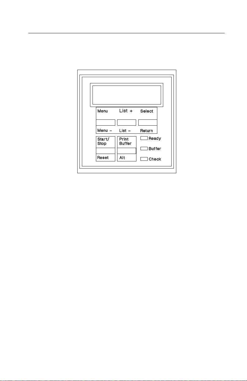
Operator Panel
You can access various printing functions and options using the
printer’s operator panel.
Indicators
There are several indicators in the operator panel that show the status of the machine.
Display
status, menu items and error messages.
For example, a star (*) is displayed when the printheads are capped.
Ready
the printer is off-line. The Ready indicator is turned off when
Stop
paper, or when
Buffer
printer. When the buffer indicator is on solid, it indicates the buffer is
full or a partial page is stored. Press
page.
Check
ator intervention, such as ink or paper problems. An error message
will also be displayed, indicating the type of problem.
This 2-line liquid crystal display (LCD) shows the printer’s
This indicator is on when the printer is on-line and is off when
Start/
is pressed, when there is a check condition such as out-of-
has been pressed to display the menu.
Menu
This indicator blinks when data is being received by the
Print Buffer
The Check indicator lights up when the printer requires oper-
to print the stored
General Information
1-4
Page 16

4079-00X
Buttons
Five buttons on the operator panel control the printer. There are two
operations for each button, depending on the state of the printer and
whether Alt is pressed.
1. Menu and Menu -
Press Menu to display the menu system, whether the printer is
Ready or Not-Ready. If a job is active, the Ready indicator is turned
off, and the menu is displayed after the current job has completed
printing. If the menu is already active, pressing Menu displays the
next menu item on the top line of the display.
Menu - is accessed by pressing Alt + Menu, and mov es to the pre vious menu item.
2. List+ and List -
When the menu is active, these buttons display the list of items on
the second line of the display. Press Alt + List+ (List - to move to
the previous list item.
3. Select And Return
Select only operates when the menu is active.
If the top line of the menu is active, pressing Select causes the lower
line to become active. If the lower line of the menu is activ e , pressing
Select selects the current value being display ed. If the current v alue
is a function, such as printing a test, it is executed. If the current
value is a setting, such as High Speed, it becomes the permanent
default.
Return is activated by pressing Alt + Select and it only operates
when the menu is active. If the lower line of the display is active,
pressing Alt causes the upper line of the displa y to become activ e . If
the upper line of the display is active, pressing Alt exits the menu
system in the Not-Ready state.
4. Start/Stop and Reset
If the Ready light is on, pressing Start/Stop turns off the Ready light
and the printer stops processing information. The current job will be
interrupted.
1-5
Page 17

4079-00X
If the Ready light is off, pressing
and the printer is ready to receive information.
When
Alt + Reset
tus.
5.
Print Buffer
Print Buffer
Buffer indicator is on solid, the buffer contains a partial page of information.
is used to access the secondary function on the other buttons by
Alt
pressing and holding Alt while pressing another button.
is pressed, the printer returns to its power-on sta-
and
Alt
prints the contents of the print buffer, if any. When the
Start/Stop
turns on the Ready light
Printhead Capping
The printheads are capped automatically after they have been in the
home position for a few seconds. When the printheads are capped,
a star (*) appears in the display. Do not turn the printer off without
the heads being capped. If the heads are left uncapped, the ink dries
out and print quality is affected.
Adjusting The Printhead Position Lever
The printhead position lever is the green lever attached to the carriage.
For optimum print quality, make sure this lever is adjusted according
to the density of the ink in the document and the thickness of the
paper being used. Setting the lever at position 1 sets the distance
between the printhead and the paper at the minimum distance.
Follow these recommendations:
Position 1
the paper.
Position 2
Position 3
very densely inked graphics.
: Use for normal documents with normal ink density on
: Use for documents with densely inked graphics.
: Use for envelopes or thick paper, or for documents with
General Information
1-6
Page 18

4079-00X
If the head is positioned too close to thick paper, envelopes, or
densely inked graphics, the ink could be smeared. In general, keep
the head position as close as possible to the paper.
Also, be sure that quality coated paper is being used for best print
quality.
Abbreviations
ASIC Application-Specific Integrated Circuit
CSU Customer Setup
DRAM Dynamic Random Access Memory
EEPROM Electrically Erasable Programmable Read-
Only Memory
EP Electrophotographic Process
ESD Electrostatic Discharge
FRU Field Replaceable Unit
HVPS High Voltage Power Supply
LAN Local Area Network
LASER Light Amplification by Stimulated Emission
of Radiation
LCD Liquid Crystal Display
LED Light-Emitting Diode
LVPS Low Voltage Power Supply
NVRAM Nonvolatile Random Access Memory
OEM Original Equipment Manufacturer
PICS Problem Isolation Charts
PIXEL Picture Element
POR Power-On Reset
POST Power-On Self Test
PQET Print Quality Enhancement Technology
RIP Raster Image Processor
ROS Read-Only Storage
SRAM Static Random Access Memory
UPR Used Parts Replacement
VAC Volts alternating current
VDC Volts direct current
1-7
Page 19

4079-00X
2. Diagnostic Information
Start
When the covers are remov ed, y ou will get a Cov er Open error code.
To prevent this, tape the cover open interlock arm in the closed position on the operator panel.
All voltages in the service checks are positive unless otherwise
noted. When measuring voltages, always use frame ground unless
otherwise specified.
Visually check the machine for obvious problems such as ink leakage, and worn or missing parts. Also reseat all cables, and check for
good connections.
Note the error code number, if one is displa yed in the oper ator panel,
and the number of beeps sounded. If you have an error code, go to
the “Error Code Table” on page 2-2 and follow the instructions for
that error code.
If no error code is present, check the NVRAM for the Last Error
code. (See the procedure in “Controller Diagnostics” on page 3-9).
If no error code number is displayed, or you cannot access Controller Diagnostics to check the last error code, or you have no clear
symptom, continue with this Start procedure.
If you proceed through Start, the Error Code T ab le, and the Operator
Codes and Symptom Table without determining an error code or
symptom, go to “Undetermined Problem Service Check” on page
2-47 and then return here to Start.
When a service check instructs you to end the call, you should run
“Test Print A” on page 3-3.
Check the following:
1. Turn the printer off. Make sure the carriage lock is disengaged,
then turn the printer on. If there is no indication of power in the
printer, go to the “Power Supply Service Check” on page 2-39.
Diagnostic Information 2-1
Page 20

4079-00X
2. If the printer has power but does not complete POST, with
Ready on the display, go to the “Operator Panel Service Check”
on page 2-31.
3. Run Test Print A. To enter Controller Diagnostics, press and
hold Menu and Print Buffer while turning on the printer. After the
POST is complete, the first item in the Controller Diagnostics
menu is displayed. Use coated paper if a vailable. If you use regular paper, allow f or some color conv ergence. If an error code or
detectable symptom occurs, go to the “Error Code Table”. If you
have a symptom only, go to the “Operator Codes And Symptom
Table” on page 2-8.
4. Turn the printer off and connect it to a host computer. Turn the
printer on and send data from the computer to the printer. You
can use the test print for this. If the data does not print as it was
sent, go to the “Host Print Service Check” on page 2-22.
Error Code Table
To use this error code table:
1. Turn off the printer, wait four or more seconds, then turn on the
printer.
2. Note any error code number that appears in the display, look for
that code in the tables below, and take the indicated action.
•
If two error codes are listed in the table: the top number is displayed if the controller board is installed; the bottom number is
displayed if the controller board is removed.
•
Some error codes are operator-correctable. See “Operator
Codes And Symptom Table” on page 2-8.
•
Other codes indicate the printer is performing an operation; no
action is needed. For example, “04 Reset”, or “05 Self Test”
means the printer is running POST.
3. If no error code is displayed, count the number of beeps and
look for that number in the tables.
4. If no error code is displayed, and no beeps are heard, look for
the symptom in the table and take the indicated action.
5. If you are unable to correct the problem using this index, go to
the “Undetermined Problem Service Check” on page 2-47.
Note: If POST fails and a message is displayed, disregard the message and count the number of beeps.
2-2
Page 21

4079-00X
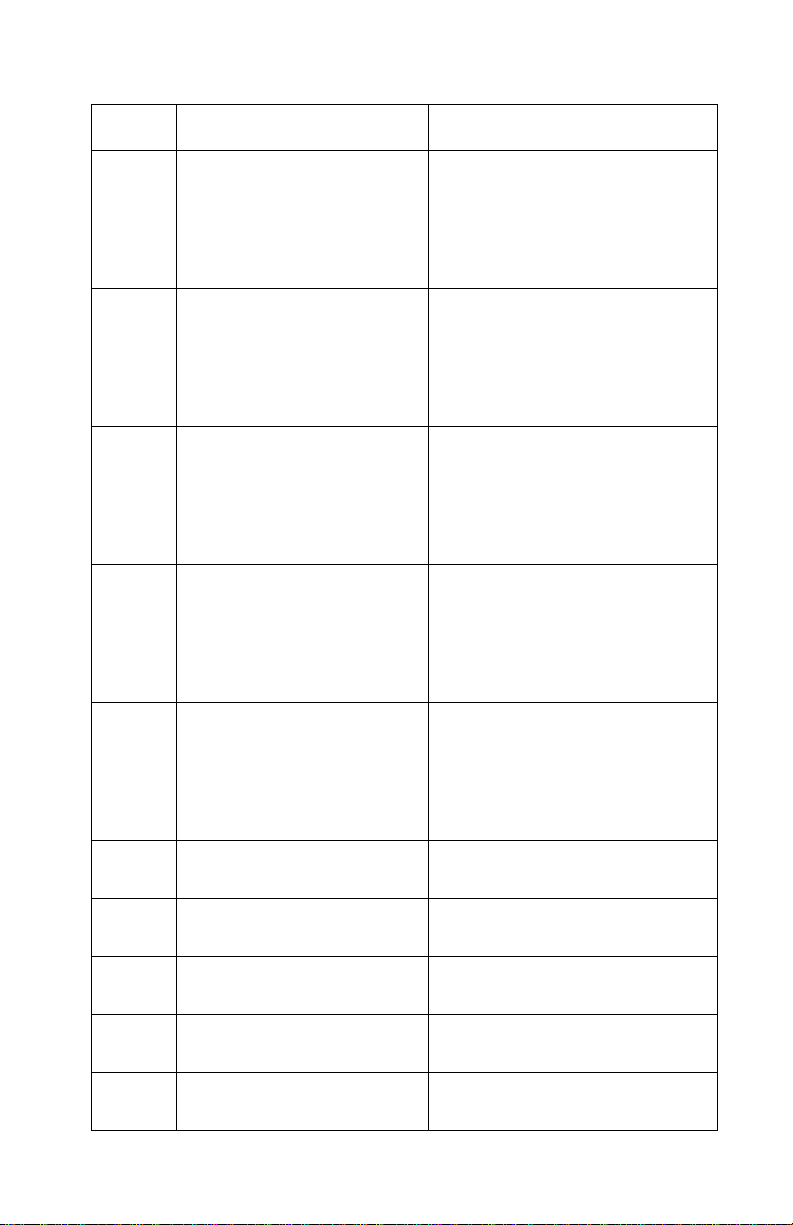
Logged Error Code
If no error code number is displayed, you can enter Controller Diagnostics mode and check for Last Error code number . See “Controller
Diagnostics” on page 3-9.
Code No Of Beeps Or Symptom Action Or Failing Fru
101
65
102
65
103
65
104
65
1 Beep - ROM error Logic board. If you replace the
logic board, go to the “Service
Adjustment Mode” on page 4-4
and perform the print position
adjustment, and the direction offset adjustment.
2 Beeps - RAM error Logic board. If you replace the
logic board, go to the “Service
Adjustment Mode” on page 4-4
and perform the print position
adjustment, and the direction offset adjustment.
3 Beeps - Printer controller Logic board. If you replace the
logic board, go to the “Service
Adjustment Mode” on page 4-4
and perform the print position
adjustment, and the direction offset adjustment.
4 Beeps - Logic board. If you replace the
logic board, go to the “Service
Adjustment Mode” on page 4-4
and perform the print position
adjustment, and the direction offset adjustment.
105
65
106
65
5 Beeps - “Logic Board And Related Cables
Service Check” on page 2-29.
6 Beeps - “Logic Board And Related Cables
Service Check” on page 2-29.
Diagnostic Information
2-3
Page 22

4079-00X
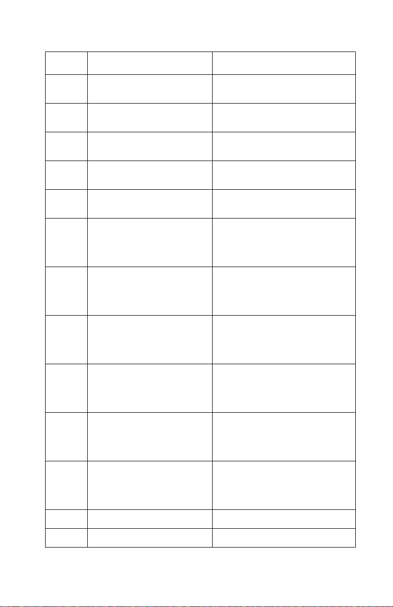
Code No Of Beeps Or Symptom Action Or Failing Fru
107
65
none No Beeps - Operator panel
108
65
109
68
125
72
126
72
127
72
7 Beeps “Logic Board And Related Cables
does not work correctly (buttons or display)
8 Beeps - Read/write error Logic board
10 Beeps - NVRAM error Logic board
10 Beeps - Controller carriage motor disable
10 Beeps - Communications error
10 Beeps - Communications error
Service Check” on page 2-29.
“Operator Panel Service Check”
on page 2-31.
Logic board. If you replace the
logic board, go to the “Service
Adjustment Mode” on page 4-4
and perform the print position
adjustment, and the direction offset adjustment.
Logic board. If you replace the
logic board, go to the “Service
Adjustment Mode” on page 4-4
and perform the print position
adjustment, and the direction offset adjustment.
Logic board. If you replace the
logic board, go to the “Service
Adjustment Mode” on page 4-4
and perform the print position
adjustment, and the direction offset adjustment.
128
72
128
72
2-4
10 Beeps - Communications error
10 Beeps - Communications error
Logic board. If you replace the
logic board, go to the “Service
Adjustment Mode” on page 4-4
and perform the print position
adjustment, and the direction offset adjustment.
Logic board. If you replace the
logic board, go to the “Service
Adjustment Mode” on page 4-4
and perform the print position
adjustment, and the direction offset adjustment.
Page 23
4079-00X
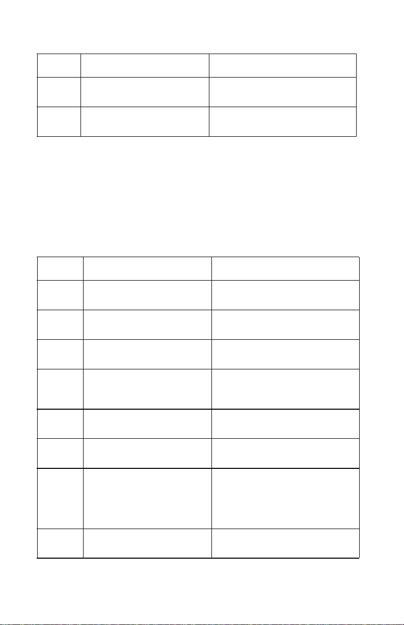
Code No Of Beeps Or Symptom Action Or Failing Fru
138
61
none,
63
none,
66
none,
72
none,
40
10 Beeps - ROM error Logic board. If you replace the
logic board, go to the “Service
Adjustment Mode” on page 4-4
and perform the print position
adjustment, and the direction offset adjustment.
10 Beeps - RAM error Logic board. If you replace the
logic board, go to the “Service
Adjustment Mode” on page 4-4
and perform the print position
adjustment, and the direction offset adjustment.
10 Beeps - Printer controller
error
10 Beeps - Communications error
10 Beeps - Communications error
Logic board. If you replace the
logic board, go to the “Service
Adjustment Mode” on page 4-4
and perform the print position
adjustment, and the direction offset adjustment.
Logic board. If you replace the
logic board, go to the “Service
Adjustment Mode” on page 4-4
and perform the print position
adjustment, and the direction offset adjustment.
Logic board. If you replace the
logic board, go to the “Service
Adjustment Mode” on page 4-4
and perform the print position
adjustment, and the direction offset adjustment.
110
55
111
54
112
53
113
52
120
55
10 Beeps - Yellow head
heat-pulse resistance error
10 Beeps - Magenta head
heat-pulse resistance error
10 Beeps - Cyan head heatpulse resistance error
10 Beeps - Black head heatpulse resistance error
10 Beeps - Yellow head temperature detection error
“Head Heater Service Check” on
page 2-20.
“Head Heater Service Check” on
page 2-20.
“Head Heater Service Check” on
page 2-20.
“Head Heater Service Check” on
page 2-20.
“Head Temp/Heat Pulse Service
Check” on page 2-20.
Diagnostic Information
2-5
Page 24

4079-00X
Code No Of Beeps Or Symptom Action Or Failing Fru
121
54
122
53
123
52
124
5F
12C,
5F
12A,
51
12B,
50
12D,
50
12E,
5E
12F
5E
10 Beeps - Magenta head
temperature detection error
10 Beeps - Cyan head temperature detection error
10 Beeps - Black head temperature detection error
10 Beeps - Printer internal
temperature error - Check
installation temperature
standards
10 Beeps - Carriage motor
drive data error
10 Beeps - Cap position
error
10 Beeps - Linear encoder
error
10 Beeps - Home position
detection error
10 Beeps - Carriage motor
over-current error
10 Beeps - POST does not
complete
“Head Temp/Heat Pulse Service
Check” on page 2-20.
“Head Temp/Heat Pulse Service
Check” on page 2-20.
“Head Temp/Heat Pulse Service
Check” on page 2-20.
Check installation temperature
standards. “Carriage Motor Drive
Data Service Check” on page
2-13.“
“Carriage Motor Drive Data Service Check” on page 2-13.
“Head Cap Position Service
Check” on page 2-18.
“Print Escapement Service
Check” on page 2-41.
“Print Escapement Service
Check” on page 2-41.
“Carriage Position Service
Check” on page 2-14.
“Carriage Position Service
Check” on page 2-14.
12F
5F
130
59
131
58
132
57
133
56
134
5D
2-6
10 Beeps - Complete POST;
Test Print A will not run
10 Beeps - Yellow head
heater error
10 Beeps - Magenta head
heater error
10 Beeps - Cyan head
heater error
10 Beeps - Black head
heater error
10 Beeps - Yellow head ink
sensor error
“Carriage Motor Drive Data Service Check” on page 2-13.
“Head Heater Service Check” on
page 2-20.
“Head Heater Service Check” on
page 2-20.
“Head Heater Service Check” on
page 2-20.
“Head Heater Service Check” on
page 2-20.
“Ink Sensor Service Check” on
page 2-26.
Page 25
4079-00X
Code No Of Beeps Or Symptom Action Or Failing Fru
135
5C
136
5D
137
5A
901 Insufficient memory to run
941 Incorrect checksum
945 Controller board failure Controller board. Be sure to
946 Controller board failure Controller board. Be sure to
950 Controller board failure Controller board. Be sure to
10 Beeps - Magenta head
ink sensor error
10 Beeps - Cyan head ink
sensor error
10 Beeps - Black head ink
sensor error
POST
(EPROM)
“Ink Sensor Service Check” on
page 2-26.
“Ink Sensor Service Check” on
page 2-26.
“Ink Sensor Service Check” on
page 2-26.
“RAM (Memory) Service Check”
on page 2-46.
EPROM Controller board (J7),
RAM (J8) (4079-002)
transfer the EPROM controller
card and memory SIMMs from
the old board to the new one.
transfer the EPROM controller
card and memory SIMMs from
the old board to the new one.
transfer the EPROM controller
card and memory SIMMs from
the old board to the new one.
951 Controller board failure Controller board. Be sure to
transfer the EPROM controller
card and memory SIMMs from
the old board to the new one.
952 Controller board failure Controller board. Be sure to
transfer the EPROM controller
card and memory SIMMs from
the old board to the new one.
953 Controller board failure Controller board. Be sure to
transfer the EPROM controller
card and memory SIMMs from
the old board to the new one.
960 Memory error Controller board RAM (J5 or J8)
961 Memory Error Memory SIMM failure, J8
Diagnostic Information
2-7
Page 26
4079-00X
Code No Of Beeps Or Symptom Action Or Failing Fru
980 Incorrect checksum
(EPROM)
991 8 Beeps - communications
error
Controller board EPROM (J6),
RAM (J5 or J8)
“Undetermined Problem Service
Check” on page 2-47.
Operator Codes And Symptom Table
The following code numbers are operator instructions and messages. In some cases, no action is required; others are operator-correctable; others may require service. An error code may require up
to one minute to appear. Some symptoms ma y not generate an error
code. Locate your symptom in the table and take the indicated
action. .
Code Beeps - Symptom Action Or Fru
05 Po wer-on self-test (POST) is
being performed.
06 Print test or other menu
function being performed.
07 Printhead cleaning operation
being performed.
08 Page Postscript due to lan-
guage error; ending when
End of Job is found.
No Action
No Action
No Action
No Action
09 Printhead refresh operation
being performed.
Not
Active
22
13
23 Paper too short to print data;
A key was pressed that is
currently not active.
Paper feeds into printer , then
jams; error code displayed
when carriage moves from
home position when printing
Test Print A.
extra data will be discarded.
2-8
No Action
Release the key. Wait until the
key is active.
Check and clear paper path. If
error persists, go to “Paperfeed
Electrical Service Check” on
page 2-32.
Use correct length paper.
Page 27
4079-00X
Code Beeps - Symptom Action Or Fru
31 Paper loaded is incorrect
size; correct size indicated
on second line of display.
36
10
none Paperfeed problem; more
none No pickup of paper; paper-
none Paper skews. “Paperfeed Mechanical Service
none 1 Beep - completes POST. A
36 1 Beep - completes POST.
Paper tray empty or paper
did not feed; POST completes, tries to feed paper
when printing Test Print A;
paperfeed motor does not
rotate.
than one sheet feeds into
printer; pickup plate repeatedly raises and lowers while
printing.
feed roller turning normally.
bumping or scraping noise is
heard during printing.
When Test Print A is run,
printer feeds paper into
printer; error code appears
at different positions of carriage
Change paper size loaded.
Load paper tray. If error persists,
go to “Check Paper Service
Check” on page 2-15.
“Paperfeed Mechanical Service
Check” on page 2-36.
“Paperfeed Mechanical Service
Check” on page 2-36.
Check” on page 2-36. Paper tray
overloaded; wrong type of media
used or selected.
Printhead cover not in place correctly.
“Paperfeed Electrical Service
Check” on page 2-32.
none Paper sticks together . F an paper; put less in paper tray.
30
12
38,
SIMMS
Top cover open “Cover Open Service Check” on
Insufficient printer memory
to print page
page 2-17.
Make page less complicated.
Add memory to printer.
Diagnostic Information
2-9
Page 28
4079-00X
Code Beeps - Symptom Action Or Fru
54 Serial error (framing or par-
60
16
61
16
62
16
63
16
64
14
65
14
66
14
67
14
ity) detected; possibly the
serial link is set up incorrectly.
Black ink cartridge empty “Ink Sensor Service Check” on
Yellow ink cartridge empty “Ink Sensor Service Check” on
Magenta ink cartridge empty “Ink Sensor Service Check” on
Cyan ink cartridge empty “Ink Sensor Service Check” on
Black ink cartridge not
installed
Yellow ink cartridge not
installed
Magenta ink cartridge not
installed
Cyan ink cartridge not
installed
Press Start/Stop to continue.
Once the serial error has been
displayed, serial error reporting is
suppressed until interface parameters are changed or printer is
powered off.
page 2-26.
page 2-26.
page 2-26.
page 2-26.
“Ink Cartridge Service Check” on
page 2-22.
“Ink Cartridge Service Check” on
page 2-22.
“Ink Cartridge Service Check” on
page 2-22.
“Ink Cartridge Service Check” on
page 2-22.
72 Disk Full No Action
73 Unformatted Disk No Action
74 Defective Disk Replace the disk.
none Missing data or additional
data in print job.
none Bad print quality; missing
dots, white streaks. Ink flow
observed through large
purge waste lines.
none Light print followed by voids
in print, in one color or all
colors; no ink flow through
large purge waste lines
“RAM (Memory) Service Check”
on page 2-46.
Clean heads. Seat ink cartridges
firmly. Check type of media
selected. “Print Quality Service
Check” on page 2-43.
“Ink Flow Service Check” on
page 2-24.
2-10
Page 29
4079-00X
Code Beeps - Symptom Action Or Fru
none Blurring or smudging of print Printhead position lever too low.
Wrong type of media. Wrong
print mode selected see “Printing
Mode” on page 3-4.
none Smeared print, poor quality Printhead position lever in wrong
none Failing LED or button on
operator panel; printer operates normally otherwise.
none 1 Beep - POST completed,
but operator panel does not
operate normally
none No lights or beeps; printer
will not begin POST
none All LEDs are on; POST
started; display blank.
none 8 Beeps - POST started; all
LEDs are on, display blank.
none 10 Beeps - POST started; all
LEDs on, display blank.
none Printer will not print from
host computer; Test Print A
runs normally.
position see “Adjusting The Print-
head Position Lever” on page
1-6.“Print Quality Service
Check” on page 2-43.
“Diagnostic Aids” on page 3-1.
“Operator Panel Service Check”
on page 2-31.
“Power Supply Service Check”
on page 2-39.
“Power Supply Service Check”
on page 2-39.
“Power Supply Service Check”
on page 2-39.
“Power Supply Service Check”
on page 2-39.
Make sure printer is on-line “Host
Print Service Check” on page
2-22.
none Carrier motor stops in the
error
code
middle of the writing line.
Symptom or error code not
listed
Go to the “Paperfeed Electrical
Service Check” on page 2-32.
“Undetermined Problem Service
Check” on page 2-47.
Diagnostic Information
2-11
Page 30

4079-00X
Service Checks
Carriage Drive Service Check
Symptom Explanation
You have an error code or
a failing carriage drive
motor.
FRU Action
1 • Carriage
Drive Motor
• Carriage
Board
• Logic Board
Conditions That Could Cause This
Symptom
• Carriage motor
• Logic board
Check the carriage drive motor winding resistance.
Connector pins 5 and 6 are one phase; pins 7 and 8
are the other phase. The resistance should be
approximately 0.8 Ohms per phase.
If the resistance is incorrect, replace the carr iage
drive motor.If the resistance is correct, replace the
carriage board.
If you still have a problem, replace the logic board. If
you replace the logic board, go to the “Service
Adjustment Mode” on page 4-4 and perform the print
position adjustment, and the direction offset adjustment.
2-12
Page 31

4079-00X
Carriage Motor Drive Data Service Check
Symptom Explanation
You have an error code
indicating a carriage drive
data error.
Conditions That Could Cause This
Symptom
• Carriage belt and idler assembly
• Carriage motor
• Linear encoder/paper width sensor
• Carriage board
• Logic board
Be sure the printer is not installed in an unusually hot or cold environment. See
for installation standards.
ence
FRU Action
1 Belt and Idler
Assembly
2 • Carriage
Motor
• Carriage
Motor Cable
• Linear
Encoder/
Paper Width
Sensor
the Lexmark Color Jetprinter 4079 Plus User’s Refer-
Proper belt tension is required for good escapement.
Check the condition of the belt and idler assembly.
Replace any damaged or worn parts.
The carriage motor and linear encoder/paper width
sensor assembly work together to move the carriage
and maintain proper escapement. Check the carriage motor cable for continuity and then replace the
following FR Us in the order shown to see if the error
code is recovered and the machine completes
POST.
1. Carriage Motor
2. Carriage Motor Cable
3. Linear Encoder/Paper Width Sensor
3 • Carriage
Board
• Carriage Ribbon Cable
• Logic Board
The carriage motor transfers signals to the carriage
board on the logic board. If an incorrect signal is
received and error code is displayed. Chec k the continuity of the carriage ribbon cables. If the cables are
all right, replace the carriage board. If the error
doesn’t go away, replace the logic board. If you
replace the logic board, go to the “Service Adjust-
ment Mode” on page 4-4 and perform the print posi-
tion adjustment, and the direction offset adjustment.
Diagnostic Information
2-13
Page 32

4079-00X
Carriage Position Service Check
Symptom Explanation
You have an error code
indicating a carriage motor
or carriage linear encoder/
paper width sensor error.
Conditions That Could Cause This
Symptom
• Carriage lock
• Carriage drive path obstructed
• Carriage belt or idler
• Carriage motor
• Print timing slit
• Brown carriage ribbon cables
• Linear Encoder/Paper Width Sensor
• Logic board
The carriage should attempt to move when the machine is turned
on. If it does not, go to the “Carriage Motor Drive Data Service
Check” on page 2-13.
FRU Action
1 Carriage Lock The carriage lock is used to hold the carriage in a
2 • Carriage
Drive Belt
• Idler Pulley
locked position during shipping or to prevent unauthorized use. Be sure the lock is in the unlocked
position. Replace it if it is damaged.
Be sure the carriage drive belt and the idler gear are
not damaged.
3 Print Timing Slit The print timing slit has coded carriage escapement
identification on it. If the characters are not printed in
their correct positions, the timing slit may be damaged and must be replaced. Check for dirt, damage,
or folds.
4•Brown Car-
riage Ribbon
Cables
• Carriage Linear Encoder/
Paper Width
Sensor
The carriage linear encoder checks the position of
the carriage by reading timing data on the timing slit.
If the linear encoder is failing, the carriage loses
position and an error codes is displayed.
Check the brown carriage ribbon cables for continuity. If the continuity is incorrect, replace the carriage
linear encoder (Asm 9-2).
2-14
Page 33

4079-00X
FRU Action
5 Logic Board If the characters are printed in their correct position
and you still receive an error code, replace the logic
board. If you replace the logic board, go to the “Ser-
vice Adjustment Mode” on page 4-4 and perform the
print position adjustment, and the direction offset
adjustment.
Check Paper Service Check
Symptom Explanation
Paper insertion problems;
Paper tries to enter
machine; error code 36/
10 displayed.
FRU Action
1 Pickup Roller A dirty pickup roller can cause paper timing prob-
lems. Visually check the paperfeed parts. If necessary, clean the pickup roller with a clean cloth and
isopropyl alcohol.
Conditions That Could Cause This
Symptom
• Dust on pickup roller
• Paperfeed motor drive
• Paper out photo sensor
Diagnostic Information
2-15
Page 34

4079-00X
FRU Action
2 Paper Out
Photo Sensor
Paper Out
Photo Sensor
Cable
Check the paper sensor signal at CNPE pin 1 on the
right connector card, with the card plugged in.
You can manually feed paper to check this signal.
Push the paper lift spring clutch plate (Asm.20-10) to
the right, and turn the rear ejector roller (Asm. 18-2).
The spring plate is under the carriage shaft to the
left of the carriage motor.
Voltage should be high (4-5 V dc) when the paper
sensor arm blocks the light path (paper is not
present).
Voltage should be low (<2 V dc) when the paper
sensor arm does not block the light path (paper is
present).
If the voltage is not correct, remove the card cover
(asm. 4-8), then adjust the paper out photo sensor
holder mounting screw so the sensor is as high in its
slot as possible. Check the voltages again. If the
voltages are still not correct, replace the paper out
photo sensor or the paper out photo sensor cable as
needed.
If the symptom remains, replace the logic board. If you replace the
logic board, go to the “Service Adjustment Mode” on page 4-4 and
perform the print position adjustment, and the direction offset adjustment.
2-16
Page 35

4079-00X
Cover Open Service Check
Symptom Explanation
The Cover Open message is displayed with the
inner cover closed.
FRU Action
1 Inner Cover The inner cover actuates the operator panel cover
interlock lever. Check the cover for damage and be
sure it can fully close.
2 Operator Panel A damaged or obstructed cover interlock lever
located on the operator panel will not allow the cover
open sensor to turn off the Open Cover message.
Remove any obstructions or replace the operator
panel if it is damaged.
3 Logic Board The Open Cover message is sent from the logic
board when the operator panel cover interlock is not
pushed down. Push the lever down, if the Open
Cover message does not go off, replace the logic
board.
If you replace the logic board, go to the “Service
Adjustment Mode” on page 4-4 and perform the print
position adjustment, and the direction offset adjustment.
Conditions That Could Cause This
Symptom
• Inner cover not closed correctly
• Operator panel
• Logic board
Diagnostic Information
2-17
Page 36

4079-00X
Hard Disk Service Check
FRU Action
1 Hard Disk Inter-
face Card
2 Hard Disk Enter the Controller Diagnostic Menu
Be sure the hard disk interface card is correctly
installed and not damaged.
Select Disk Menu and run the Quick Disk T est. If you
get a failure, replace the hard disk.
If you do not have the disk menu in the Diagnostic
Menu, check for proper installation of the hard disk
and the hard disk interface card.I
Head Cap Position Service Check
Symptom
Explanation
You have an error
code or a purge
motor or purge sensor failure.
Turn on the printer and observe the purge motor. If the motor does
not run, go to the “Purge Unit Service Check” on page 2-45.
Conditions That Could Cause This
Symptom
• Purge motor
• Purge sensor, cable assembly
• Purge assembly
• Left connector cable
• Logic board
FRU Action
1 Purge Sensor
Cable Assembly
2-18
1. Center the heads. See “Printhead Uncapping and
Carriage Centering” on page 4-9.
2. Turn off the printer.
3. Remove the purge assembly and lay it on its side.
Use absorbent material to protect from leaking
ink.
4. Check the sensor on the bottom of the purge
assembly. If it is broken, or has dirty contacts,
replace it.
Page 37

4079-00X
FRU Action
2 Purge Assem-
bly
• Left Connector Cable
• Logic Board
Be sure all the ink lines are connected.
With the purge assembly removed and laying on its
side, check the voltage on the contact straps. The
voltage should be +5 V dc with the contacts open.
As the contacts close, the voltage should drop to 0
V dc.
If the voltage is incorrect, check the continuity of the
left connector cable. If the continuity is incorrect,
replace the cables as needed. If the continuity is correct, replace the logic board. If you replace the logic
board, go to the “Service Adjustment Mode” on page
4-4 and perform the print position adjustment, and
the direction offset adjustment.
Diagnostic Information
2-19
Page 38

4079-00X
Head Heater Service Check
Symptom Explanation
You have a head heater
error code.
FRU Action
1 Printhead Use the codes in the“Error Code Table” on page 2-2
to identify the printhead you think may be failing. Be
sure the printhead is seated properly and the head
cover is fully closed.
2 Brown Carriage
Cables
3 • Carriage
Board
• Logic Board
• Printhead
Check the continuity of the brown carriage cables.
Replace if necessary.
Replace the carriage board and run Test Print A to
check the print quality.
If the problem is not corrected, replace the logic
board. Be sure to go to the “Service Adjustment
Mode” on page 4-4 and perform the print position
adjustment, and the direction offset adjustment.
If the problem is still not corrected, replace the print-
head.
Conditions That Could Cause This
Symptom
• Carriage board
• Logic board
• Printhead
• Carriage cables
Head Temp/Heat Pulse Service Check
Symptom Explanation
You have an error code
indicating a head temperature error or heat pulse
resistance error.
2-20
Conditions That Could Cause This
Symptom
• Printhead
• Carriage board
• Logic board
Page 39

4079-00X
FRU Action
1 • Printhead
• Carriage
Board
Use the codes in the“Error Code Table” on page 2-2
to identify the printhead you think may be failing. Be
sure the printhead is seated properly and the head
cover is fully closed.
Check the voltage to the printhead as read by the
analog switch IC2 on the carriage board.Check the
resistance and voltage between each pin and frame
ground. Be sure to turn off the printer when you
check resistance.
Black Head - pin 12 should read 2k - 4k Ohms, and
1.02 - 5.03 V dc. Black head, pin 4 should read 1.74
- 4.46 V dc.
Cyan Head - pin 15 should read 2k - 4k Ohms, and
1.02 - 5.03 V dc. Cyan head, pin 2 should read 1.74
- 4.46 V dc.
Magenta Head - pin 14 should read 2k - 4k Ohms,
and 1.02 - 5.03 V dc. Magenta head, pin 1 should
read 1.74 - 4.46 V dc.
Yellow Head - pin 13 should read 2k - 4k Ohms, and
1.02 - 5.03 V dc. Y ellow head, pin 5 should read 1.74
- 4.46 V dc.
If the signals are incorrect, replace the defective
printhead. If the signals are correct, replace the carriage board.
Diagnostic Information
2-21
Page 40

4079-00X
If the problem is not corrected, replace the logic board. Be sure to go
to the “Service Adjustment Mode” on page 4-4 and perform the print
position adjustment, and the direction offset adjustment.
Host Print Service Check
Symptom Explanation
The printer does not communicate with the host
computer.
FRU Action
1 • Incorrect Pro-
tocol Set
• Controller
Board
Run Test Print A.To enter Controller Diagnostics,
press and hold Menu and Print Buffer while turning
on the printer. After the POST is complete, the first
item in the Controller Diagnostics menu is displayed.
If the test runs successfully, disconnect the serial/
parallel interface cable, install the wrap plug (PN
1319128), and then run the wrap test (see “Paper
Load Test” on page 3-10. If the test fails, replace the
controller board.
Conditions That Could Cause This
Symptom
• Incorrect protocol set
• Controller board
Ink Cartridge Service Check
Symptom Explanation
Conditions That Could Cause This
Symptom
The printer does not
sense an ink cartridge
when one is installed.
• Cartridge detection resistor
• Cartridge sensor cable
• Cartridge sensor
If you are instructed to remove the ink cartridge assembly, it is recommended that you remove all ink cartridges, carefully drain the ink
from the lines into a plastic-lined waste can or absorbent material,
then replace the cartridges and wrap a packet of cleaning cloths or
paper towels over the connector end, secured with a rubber band.
2-22
Page 41

4079-00X
Keep the assembly on a level plane while servicing with the black
cartridge end slightly elevated. Cover any open ink lines with absorbent cloth, secured with a rubber band, when possible.
FRU Action
1 Ink Cartridge The error code should indicate which cartridge is
2 Logic Board Disconnect the CNID connector from the left con-
3 • Sensor Cable
• Ink Cartridge
Sensor
suspected. Check the ink cartridge detection resistor
pad (top left of each cartridge). The resistance
should be 15K to 25K Ohms. If the resistance is
incorrect, replace the ink cartridge.
nector card. With the ink cartridge installed, check
the resistance between the pins designated for each
cartridge sensor (pins 1 and 2; 3 and 4; 5 and 6; 7
and 8). Pin 9 is not used. The resistance should be
correc
15K to 25K Ohms. If the resistance is
replace the logic board, left connector card, and left
connector cable.
If you replace the logic board, go to the “Service
Adjustment Mode” on page 4-4 and perform the print
position adjustment, and the direction offset adjustment.
Remove the ink cartridge assembly . Check the continuity on the sensor cable. Match pin numbers at
both ends of the cable.
t,
If the continuity is correct, replace the ink cartridge
sensor. If the continuity ius incorrect, replace the
sensor cable.
Diagnostic Information
2-23
Page 42

4079-00X
Ink Flow Service Check
Symptom Explanation
You have no ink flow, with
no error code displayed.
Conditions That Could Cause This
Symptom
• Ink Cartridge Supply Lines
• Carriage supply and waste lines
• Purge waste lines
• Ink cartridge waste lines
• Purge Unit
• Ink supply assembly
• Printhead
Important: A long cleaning uses a significant amount of ink. To minimize ink flow while you troubleshoot ink flow problems, it is helpful
to be familiar with normal ink flow. If needed, study the “Ink Supply
Diagram” on page 5-6, and the text on the following page. Start with
the flow of ink from the ink cartridge.
It is also helpful to be familiar with this service check. Read the
entire service check to become familiar with the parts you need to
check. Check as many parts as possible during the long cleaning
rather than performing a long cleaning for each step.
FRU Action
1 • Carriage Ink
Supply
Assembly
• Ink Cartridge
Supply Lines
2 Purge Unit Be sure the purge assembly motor is operating nor-
Perform a Long Cleaning. Be sure the carriage supply lines are full of ink at the cartridge assembly connection (smaller lines). If they are not, check the
carriage ink supply line for blockage. F ollow the lines
to see whether they are filled or empty.
mally. If it is not, replace it.
Be sure the carriage waste lines at the purge
assembly connector are full of ink. If they are not,
replace the carriage ink supply assembly (Asm.
10-1).
Be sure ink flows through the large purge waste
lines when the purge motor runs. If it does not,
replace the purge unit.
2-24
Page 43

4079-00X
FRU Action
3 Carriage Ink
Supply Assembly
4 • Ink Cartridge
Assembly
Waste Lines
• Ink Cartridge
5 Printhead Be sure ink is flowing through the ink supply assem-
Be sure the carriage ink supply assembly waste
lines fill when the purge motor completes its cycle.
The purge unit discharges ink back to the ink cartridge through the waste line in the ink return unit.
Be sure the waste lines are not blocked. Also, be
sure the ink cartridge is good.
bly (asm. 10-1).
Perform a Long Cleaning.
Replace the printhead for the color that fails to flow.
Diagnostic Information
2-25
Page 44

4079-00X
Ink Sensor Service Check
Symptom Explanation
You have problems with
ink sensing. The sensor
may indicate no ink when
a good cartridge is
installed, or may fail to
indicate when the cartridge is empty.
Conditions That Could Cause This
Symptom
• Ink cartridge
• Ink sensor
• Ink sensor cable
• Logic board
If you are instructed to remove the ink cartridge assembly, it is recommended that you remove all ink cartridges, carefully drain the ink
from the lines into a plastic-lined waste can or absorbent material,
then replace the cartridges and wrap a packet of cleaning cloths or
paper towels over the connector end, secured with a rubber band.
Keep the assembly on a level plane while servicing with the black
cartridge end slightly elevated. Cover any open ink lines with absorbent cloth, secured with a rubber band, when possible.
FRU Action
1 Ink Cartridge The ink sensor determines whether an individual ink
cartridge is empty and causes an error code.
Remove the ink cartridge. Hold a cloth over the sensor end, and gently shake the cartridge. If you do not
feel or hear ink movement in the cartridge, replace it.
2-26
Page 45

4079-00X
FRU Action
2 Ink Sensor Check the ink sensor by checking for 5 V dc
between the pins designated for each cartridge sensor on the CNINK connector as you push the sensor
down and up.
Cyan = pins 1 - 2
Magenta = pins 3 - 4
Yellow = pins 5 - 6
Black = pins 7 - 8
To push down the ink sensor: insert a thin screwdriver just above the ink cartridge assembly and
below the paper lift plate, then push the ink sensor
plunger down. The voltage should be low when the
sensor is on (the center of the sensor is up), and
high when the sensor is off (the center of the sensor
is down). If the voltage is correct, replace the ink
sensor.
Diagnostic Information
2-27
Page 46

4079-00X
FRU Action
3 • Sensor Cable
• Logic Board
Check the sensor cable continuity, matching pins on
CNINK at the left connector card with wires to the
ink sensor units. If the continuity is not correct,
replace the sensor cable.
If the continuity is correct, replace the logic board. If
you replace the logic board, go to the “Service
Adjustment Mode” on page 4-4 and perform the print
position adjustment, and the direction offset adjustment.
2-28
Page 47

4079-00X
Logic Board And Related Cables Service Check
Symptom Explanation
You have problems with
the logic board or cables.
.
FRU Action
1•Brown Car-
riage Cable 2
• White Ribbon Cable 2
• Carriage
Board
• Logic Board
Conditions That Could Cause This
Symptom
• System cables
• Carriage board
• Logic board
Follow these steps if 5 beeps are sounded, checking
the error after each action:
1. Check for correct connection of the brown carriage cable 2 to the carriage board and the right
connector card.
2. Check for correct connection of the white ribbon
cable 2 to the right connector card and the logic
board.
3. Check continuity of the white ribbon cable 2 (23
pin) and brown carriage cable 2 (19 pin), checking
pin-for-pin.
4. Replace the carriage board.
5. Replace the logic board.If you replace the logic
board, go to the “Service Adjustment Mode” on
page 4-4 and perform the print position adjust-
ment, and the direction offset adjustment.
Diagnostic Information
2-29
Page 48

4079-00X
FRU Action
2•Brown Car-
riage Cable 1
• White Ribbon Cable 1
• Carriage
Board
• Logic Board
3 • Operator
Panel Cable
• Operator
Panel
• Logic Board
Follow these steps if 6 beeps are sounded, checking
the error after each action:
1. Check for correct connection of the brown carriage cable 1 to the carriage board and the right
connector card.
2. Check for correct connection of the white ribbon
cable 1 to the right connector card and the logic
board.
3. If the problem persists, check continuity of the
white ribbon cable 1 (23 pin) and brown carriage
cable 1 (19 pin), checking pin-for-pin.
4. Replace the carriage board.
5. Replace the logic board. If you replace the logic
board, go to the “Service Adjustment Mode” on
page 4-4 and perform the print position adjust-
ment, and the direction offset adjustment.
Follow these steps if 7 beeps are sounded, checking
the error after each action:
1. Make sure the operator panel cable is correctly
connected at the right connector card.
2. Replace the operator panel. Replace the logic
board. If you replace the logic board, go to the
“Service Adjustment Mode” on page 4-4 and per-
form the print position adjustment, and the direction offset adjustment.
2-30
Page 49

4079-00X
Operator Panel Service Check
Symptom Explanation
Nothing appears on the
display, buttons or LEDs
fail, but the printer starts
POST.
FRU Action
1 Power Supply 1. Disconnect the power supply connector from the
controller board.
2. Remove the controller board.
3. Check for 5 V dc at pin 2 of the CNPOW connector with the connector plugged into the logic
board. If it is not correct, replace the power supply.
Conditions That Could Cause This
Symptom
• Power supply
• Operator panel
• Logic board
• Controller board
2 • Operator
Panel
• Logic Board
1. Disconnect the power supply connector from the
controller board.
2. Remove the controller board.
3. T urn on the printer and see if anything displays on
the operator panel. Turn the machine off within
ten seconds to avoid going into a Long Clean.
If nothing appears on the display, replace the operator panel.
If you still have the prob lem, replace the logic board.
If you replace the logic board, go to the “Service
Adjustment Mode” on page 4-4 and perform the print
position adjustment, and the direction offset adjustment.
Diagnostic Information
2-31
Page 50

4079-00X
FRU Action
3 • Controller
Board
• Operator
Panel
Turn off the printer.
Install the controller board and connect the power
supply connector.
Press and hold MENU and Print Buffer and turn on
the printer to clear the controller diagnostic mode.
Check operation of buttons, LEDs, and LCD, see
“Controller Diagnostics” on page 3-9. If they all pass
their tests, replace the controller board. Be sure to
transfer the controller card and memory SIMMs to
the new card. If the buttons, LEDs, and LCD do not
pass the tests, replace the operator panel.
Paperfeed Electrical Service Check
Symptom Explanation
Paper eject problems; an
error code is displayed
when the carriage moves
away from home position
while printing Test Print A.
If the paper lift plate lifts more than once or feeds more than one
sheet of paper, go to the
.
2-36
Conditions That Could Cause This
Symptom
• Dirty platen
• Paper jam
• Linear encoder/paper width sensor
mounted too low, or failing
• Paper out photo sensor failing
“Paperfeed Mechanical Service Check” on page
Use the following chart to determine when the error code appears.
Turn the machine on and carefully observe when the error code
appears, then go to the appropriate FRU check.
Error Code Appears Go To
When the printer is turned on Step 1
When the carriage moves left to right as the paper is picked up. Step 2
When the carriage moves right to left as the paper is picked up Step 3
During printing when the carriage does not move correctly Step 4
2-32
Page 51

4079-00X
Error Code Appears Go To
When paper is in the printer beyond the start position of Test
Print A, or above the ejector rollers, but not beyond the platen.
FRU Action
1 • Paper Out
Sensor
• Paper Out
photo sensor
Cable
• Ribbon Cable
• Logic Board
Remove any paper that may be in the machine.
Observe the paper-out sensor arm from the rear of
the machine under the paperfeed roll. Be sure the
paper sensor arm operates smoothly, blocking the
light path of the paper-out sensor when there is no
paper in the paper path. If the light is blocked by a
foreign object, remove the object and check the
operation of the sensor arm and sensor holder.
If the light path is all right, check the paper-out voltage between pin 1 and ground on the CNPE connector on the right connector card, with the
connector plugged in.
Step 5
The voltage should be high (4 - 5 V dc) when the
paper sensor arm blocks the light path of the paperout sensor, and low (>2 V dc) when the light path is
not blocked. If the voltage is correct, replace the
logic board. If you replace the logic board, go to the
“Service Adjustment Mode” on page 4-4 and per-
form the print position adjustment, and the direction
offset adjustment.
If the voltage is not correct, check the continuity of
the paper sensor cable by matching wire colors.
Also check the continuity of the ribbon cables.
Replace the cable if necessary. If this does not fix
the problem, replace the paper-out sensor.
Diagnostic Information
2-33
Page 52

4079-00X
FRU Action
2 • Platen
• Linear
Encoder/
Paper Width
Sensor
3 • Paperfeed
Rollers
• Linear
Encoder/
Paper Width
Sensor
• Logic Board
Check the platen for bits of paper , paper dust, or ink.
Clean the platen with a wet paper towel if necessary .
When the carriage moves to pick up paper, the
paper width sensor detects the black surface of the
platen and the white surface of the paper to determine the width of the paper. Even a slight scratch
will deflect light. To check a suspected platen, cover
any scratches with small pieces of black electrical
tape, then test the printer. Remove the tape when
the repairs are complete. Check the platen surface.
If the painted surface is damaged, the paper width
sensor cannot detect the platen correctly. Replace
the platen if necessary.
If the platen is all right, replace the linear encoder/
paper width sensor and check the printer operation.
Be sure correct paper is being used.
Clean the paperfeed rollers and remove any foreign
objects from the paper path. If the paperfeed rollers
do not turn and the motor does not run go to
the“Paperfeed Motor Service Check” on page 2-38.
If the paper is being fed correctly, remove and
replace the following FRUs in sequence. Check
printer operation after each replacement.
1. Linear Encoder/Paper Width Sensor
2. Logic Board.
If you replace the logic board, go to the “Service
Adjustment Mode” on page 4-4 and perform the print
position adjustment, and the direction offset adjustment.
2-34
Page 53

4079-00X
FRU Action
4 • Timing Slit
• White Ribbon
• Brown Ribbon
• Carriage
Board
• Logic Board
5 • Eject Roller
• Pinch Roller
Be sure the carriage is unobstructed and moves
freely.
Be sure the printer is not picking up vibrations from
the environment. Move the printer to a different location if necessary.
Check the timing slit for damage, dirt, and folds.
Replace the timing slit if necessary. If the timing slit
is all right, replace the following FRUs in sequence.
Check the printer after each replacement.
1. Carriage Board
2. Logic Board
If you replace the logic board, go to the “Service
Adjustment Mode” on page 4-4 and perform the print
position adjustment, and the direction offset adjustment.
Check for foreign objects in the paper path. Also
check the rollers for wear or damage. If the paperfeed rollers do not turn, go to the “Paperfeed Motor
Service Check” on page 2-38.
Diagnostic Information
2-35
Page 54

4079-00X
Paperfeed Mechanical Service Check
Symptom Explanation
Paper indexing or feeding
problem; you may see an
error code.
FRU Action
1 Gear Train Be sure there are no foreign objects in the paper
path.
Watch the paperfeed and eject rollers during POST.
If they do not rotate, check the gear train and
replace any damaged parts. See “Paper Path” on
page 5-7.
2 Pickup Roller
Spring Plate
Run Test Print A and watch the paper lift plate while
the feed rolls are rotating. The paper lift plate should
rise and fall only one time during POST or when the
pickup roller spring (Asm. 20-10) actuates the pickup
roller assembly. If the plate does not rise and fall correctly, replace it.
Conditions That Could Cause This
Symptom
• Foreign object in path
• Paper dust or ink on rollers
• Paperfeed motor, gear train
• Paper pickup mechanism
• Paper transport mechanism
• Paper exit mechanism
• Spur unit
3 Paperfeed
Roller
4 Sheetfeed Sep-
aration Assembly
2-36
Be sure the pickup roller feeds paper into the printer.
If it does not, clean the paperfeed roller by running a
piece of brown cleaning paper through the printer, or
replace the paperfeed roller (Asm.18-3). Cleaning
paper is provided with each batch of coated printed
paper.
If more than one sheet of paper enters the paperfeed rollers, replace the sheetfeed separation
assembly or related parts (Asm. 19-21).
Page 55

4079-00X
FRU Action
5 • Pinch Roller
• Paperfeed
Roller
6 • Eject Roller
• Spur Unit
Be sure the paper moves through the paperfeed
pinch rollers onto the platen. If it does not, replace
the following FRUs in sequence. Check printer operation after each replacement.
1. Pinch Roller Assembly or related parts (Asm. 17-
1)
2. Paperfeed Roller Assembly (Asm. 18-3)
Be sure the paper moves smoothly through the eject
rollers and the inner cover spur units. If they do not,
clean or replace the eject rollers (Asm. 18-2), or
replace damaged spur unit or units (Asm. 3-1).
Diagnostic Information
2-37
Page 56

4079-00X
Paperfeed Motor Service Check
Symptom Explanation
No paperfeed roller rotation during POST or while
printing Test Print A.
FRU Action
1 Paperfeed
Motor Cable
Conditions That Could Cause This
Symptom
• Paperfeed motor
• Logic board
Watch the paperfeed motor and gears as you turn
on the printer. If the gears do not rotate, turn off the
printer and check the continuity of the paperfeed
motor cable. Notice that the pins are labeled 9 - 14
on the paperfeed motor connector , corresponding to
the same pins on the CNMOT connector on the logic
board. If the continuity is incorrect, replace the
paperfeed motor cable.
2-38
Page 57

4079-00X
FRU Action
2 Paperfeed
Motor
Check the paperfeed motor winding resistance at
the motor connector. The pins are numbered 14 - 9,
with 14 at the top of the connector. Check the resistance on four phases, each of which should have
approximately 70 Ohms resistance.
• 13 - 11
• 13 - 9
• 14 - 12
• 14 - 10
If the resistance is incorrect, replace the paperfeed
motor. If the resistance is correct, replace the logic
If you replace the logic board, go to the
board.
“Service Adjustment Mode” on page 4-4
form the print position adjustment, and the
direction offset adjustment.
Power Supply Service Check
Symptom Explanation
Conditions That Could Cause This
Symptom
and per-
The printer does not start
POST , the displa y is blank,
and there are no beeps or
lights.
FRU Action
1 Power Cord Be sure there is power at the AC outlet. Unplug the
power cord and check it for continuity.
• AC outlet
• Power cord
• Primary fuse
• Power supply
• Controller board
• EPROM Controller card
• Memory SIMM
Diagnostic Information
2-39
Page 58

4079-00X
FRU Action
2 Fuse Check the primary fuse at the power supply. If it is
3 Power Supply Turn the machine off and remove the controller
bad, replace it and check the machine again.
board and the card cover. Leave connector CNPO W
plugged into the logic board and unplug the power
supply connector from the controller board.
When you make the follo wing voltage check, turn the
power off before you connect the meter leads. Connect the meter leads then turn the power on briefly
to check the voltage. Turn the power off quickly to
avoid a cleaning cycle.
Use Pin 1 as ground and check the following voltages with the connector plugged in.
pins 1 - 2 = 5 V dc
pins 1 - 4 = 28 V dc
pins 1 - 6 = 24 V dc
Check the voltage on the power supply connector,
J4 for 4079-001 or J6 for 4079-002:
pins 1 - 5 (brown to yellow) = 5V dc
pins 3 - 5 (red to Yellow) = 5 V dc
If the voltages are incorrect, replace the power supply
2-40
Page 59

4079-00X
FRU Action
4 • Controller
Card
• EPROM Controller Card
• Memory
SIMMs
Leave the controller board removed and the power
supply disconnected. Go to the, “Service Adjustment
Mode” on page 4-4 and follow the procedure to enter
the Service Adjustment Mode with the controller
board removed. Ready or an error code should
appear in the display. If the POST does not run,
replace the power supply. If the POST does run,
remove and replace the following parts until the failure is corrected:
1. Controller Board
2. EPROM Controller Card
3. Memory SIMM J5
4. Memory SIMM J8.
Print Escapement Service Check
Symptom Explanation
You have an error code
indicating a print timing slit
error or carriage linear
encoder error.
If the carriage does not move or attempt to move when you turn on
the printer, go to the “Carriage Motor Drive Data Service Check” on
page 2-13
Conditions That Could Cause This
Symptom
• Carriage motor
• Print timing slit
• Linear encoder/paper width sensor
• Carriage board
• Logic board
Diagnostic Information
2-41
Page 60

4079-00X
Be sure there is no obstruction in the carriage drive path and that the
print timing slit is not dirty, brok en, or bent. Use a cleancloth to clean
the timing slit. If the drive path is obstructed, clear the obstruction,
then run POST to check the printer.
FRU Action
1 Carriage
Cables
2 • Linear
Encoder/
Paper Width
Sensor
• Carriage
Board
• Logic Board
Check the continuity of the brown carriage cables.
Replace the cables if necessary.
Remove and replace the following parts in the order
shown. Check the printer after each replacement to
see if the problem is solved.
1. Linear Encoder/Paper Width Sensor
2. Carriage Board
3. Logic Board
If you replace the logic board, go to the “Service
Adjustment Mode” on page 4-4 and perform the print
position adjustment, and the direction offset adjustment.
2-42
Page 61

4079-00X
Print Quality Service Check
Symptom Explanation
Print quality problems,
missing dots, colors, or ink
smearing. Possible ink
supply problem.
Conditions That Could Cause This
Symptom
• Clogged ink lines
• Printhead
• Cartridge present sensor
You are in this service check because the print sample nozzle check
indicates some nozzles may be blocked. Perform a Normal Cleaning, see “Printhead Cleaning Procedures” on page 3-4, then check
the print quality by running the “Print Sample” on page 3-3. If the
print quality is not satisfactory, perform a Long Cleaning and check
the print quality again.
Be sure the correct paper is being used (coated), and the printer is
in the correct print mode. See “Printing Mode” on page 3-4.
FRU Action
1 Ink Cartridge Remove the ink cartridge you think has a problem,
cover the sensor end with a cloth, and gently shake
the cartridge. If you cannot hear or feel ink moving,
replace the cartridge.
2 Platen Be sure the platen is not dirty or ink-stained.
Check the printhead gap. See “Head Gap Adjust-
ment” on page 4-2.
Diagnostic Information
2-43
Page 62

4079-00X
FRU Action
3 Ink Flow and
Supply Lines
4 Printhead Perform a Long Cleaning twice, then perform Test
1. Be sure the ink line connectors are not loose, disconnected, or defective.
2. Be sure the carriage is not catching on the ink
lines. Reposition the ink lines as necessary.
3. Perform a Long Cleaning, observing the carriage
supply lines, subtank ink levels, and carriage
waste lines.
4. Check for the following conditions, if they are not
correct, go to the “Ink Flow Service Check” on
page 2-24.
• The carriage supply lines are always filled with
ink.
• Ink flows through the carriage supply lines.
• The carriage subtank lev els of ink are equal f or all
colors.
• Ink from the carriage waste lines is dra wn into the
purge assembly
• Ink is pumped in pulses through the large purge
waste lines into the ink cartridge assembly.
Print A. If the print is unsatisfactory enter the “Ser-
vice Adjustment Mode” on page 4-4 and perform
Test Print A again. If the print is still unsatisfactory,
replace the printhead that failed.
2-44
Page 63

4079-00X
Purge Unit Service Check
Symptom Explanation
You are here after using
the Head Cap Position
Service Check, or
because you suspect the
purge motor is bad and
you have no ink flow.
FRU Action
1 Purge Motor Check the purge motor winding resistance. Pin 3 is
2 Purge Sensor
Cable
ground. Pins 4, 5, 6, and 7 are windings. The black
wire is pin 7. The resistance should be about 70 - 80
Ohms per phase. If it is not, replace the purge motor.
Check the continuity of the purge sensor cable (pins
1 and 2 on CNPG on the left connector card)
Replace the cable if needed.
Conditions That Could Cause This
Symptom
• Purge motor
• Purge sensor cable
• Left connector card cable
• Logic board
3 • Left Connec-
tor Cable
• Logic Board
Check the continuity of the left connector card cable.
Begin with the black wire on CNMEC on the logic
board and on the left connector card.
If the continuity is correct, replace the logic board. If
you replace the logic board, go to the “Service
Adjustment Mode” on page 4-4 and perform the print
position adjustment, and the direction offset adjustment.
Diagnostic Information
2-45
Page 64

4079-00X
RAM (Memory) Service Check
Symptom Explanation
Data is missing from your
print job, additional data
appears, or error code
960.
FRU Action
1 SIMM The printer requires 4 MB of RAM to complete
POST. If error code 960 appears, replace the SIMM
in J8, which should be 4 MB, then continue (4079001 only).
If you receive a 960 error with a 4079-002, replace
the controller board which includes the first 4MB of
RAM.
Check the RAM installed in the printer. Go to “Con-
troller Diagnostics” on page 3-9 and run the RAM
test. Note the amount of memory reported in your
printer. If the correct amount is not reported for each
SIMM, replace the faulty SIMM. If the correct
amount is reported go to the “Print Quality Service
Check” on page 2-43.
Conditions That Could Cause This
Symptom
• RAM SIMM J5 or J8 (4079-001 only)
• Logic Board (4079-002 only)
2-46
Page 65

4079-00X
Undetermined Problem Service Check
You have been directed to this service check because you cannot
find an error code or symptom in “Start” on page 2-1 or the “Error
Code Table” on page 2-2 or because more information is needed on
the symptom or error code than the Error Code/Symptom Index can
provide.
1. Turn off the printer and disconnect the power cord.
2. Disconnect the controller board power supply connector J4
(4079-001) or J6 (4079-002).
3. Remove the controller board from the machine.
The controller board stores all operator settings and contains
NVRAM and ROM memories. When the controller board is removed,
all operator settings are ignored. The printer defaults to a secondary
menu system which allows you to run Test Print A to check the
machine operation. To run Test Print A:
1. Connect the power cord and turn on the machine.
2. Wait for the machine to complete POST.
3. Press
4. Press
5. Press
6. Press
7. Make a note of the error code, number of beeps, or symptom.
8. Continue with “Start” on page 2-1.
Select
.
until Test Print is displayed.
List
Start/Stop
Start/Stop
until Test Print A is displayed.
to run the test.
If you have been directed here a second time, and POST does not
run or you have no error code or symptom, replace the following
FRUs one at a time, checking the printer operation after each
replacement.
1. Logic board - If you replace the logic board, go to the “Service
Adjustment Mode” on page 4-4 and perform the print position
adjustment, and the direction offset adjustment.
2. Controller board - Be sure to transfer the EPROM controller
card and memory SIMMs from the old board to the new one.
Reinstall the parts that do not fix the problem.
Diagnostic Information
2-47
Page 66

4079-00X
3. Diagnostic Aids
Testing The Printer
Diagnostic Aids are divided into two types of functions: Controller
Diagnostics, and Service Adjustment Mode. In addition, some test
prints can be run from the operator mode.
The tests are provided for printer testing and diagnostics. The printer
does not need to be attached to a host system to use the tests.
Using The Menu System
There is one menu in the printer, with two levels of display.
When the
rent
When the lower level of menus is displayed, the display shows the
current item on the top line, and the current value f or that item on the
bottom line.
•
•
•
•
top level
menu
on the top line, and the current item on the bottom line.
To move from the top level to the lower level of the menu, press
the Select button.
To move from the lower level to the top level of the menu, press
Alt + Select.
To scroll through the top line menu items, press Menu or Alt +
Menu (Menu -).
To scroll through the lower line menu items, press List+ or Alt +
List+ (List -).
of menus is displayed, the display shows the cur-
3-1
Page 67

4079-00X
Operator Test Functions
When the printer is turned on, it goes through a check-out routine
and indicates any failure by an error code number in the display.
Some of these codes are correctable by the operator, others can
only be repaired by a trained service person. The error codes are
listed in the “Error Code Table” on page 2-2. A normal cleaning oper-
ation is also performed when the printer is turned on.
In normal operator mode, the following Test menu appears:
4079-001)
Menu Item Value
Clean Heads
Print Test Page
4079-002:
Menu Item Value
Clean Heads
Print Test Page
The operator or service person can use these test procedures without entering Controller Diagnostics or Service Adjustment modes.
•
Normal Clean
•
Print Sample
•
Long Clean
•
PS Test Page
•
GL Test Page
•
Test Print A
•
Test Print B
•
Normal Clean
•
Print Sample
•
Long Clean
•
PS Test Page
•
GL Test Page
•
Color Sampler
•
PS 2 Fonts
Diagnostic Aids
3-2
Page 68

4079-00X
Test Print A
Test Print A prints a sample of machine settings and lines of color in
varying densities, and also drives the printer extensively.
The printer completes the test on one sheet of 215.9 by 279.4 mm
(8-1/2 by 11-inch) paper, then returns to the menu mode.
After you complete any repairs, run the print sample sev eral times to
ensure that the printer is operating correctly.
To start Test Print A for 4079-001:
1. Make sure paper is loaded in the machine and the printer is offline.
2. Press Menu twice. “Test Menu Clean Heads” is displayed.
3. Press Select.
4. Press Menu until “Print Test Page = PS Test Page” is displayed.
5. Press List+ to move through the menu until “Test Print” is displayed. (Use List - to scroll backward through the menu.)
6. Press Select when “Test Print A” is displayed. The display reads
“06 Print Test” and printing is started.
After the test print has printed, the printer returns to menu mode.
Print Sample
The Print Sample prints a short line from each nozzle, which shows
if any nozzles are clogged. To start the print sample:
1. Make sure paper is loaded in the machine and the printer is offline.
2. Press Menu twice. “Test Menu Clean Heads” is displayed.
3. Press Select
4. Press List+ to move through the menu until “Print Sample” is
displayed. (Use List - to scroll backward through the menu.)
5. Press Select. The display reads “06 Print Test” and printing is
started.
3-3
Page 69

4079-00X
After the nozzle check is printed, the printer returns to the menu
mode.
In this example, some of the nozzles are clogged, resulting in a void
in the print. You would run the head clean procedure, then run the
print sample again.
Printhead Cleaning Procedures
These procedures clean out the ink lines during diagnostic procedures or after new ink parts have been installed.
Normal Cleaning
This head cleaning procedure takes about 15 seconds. After cleaning the heads, run the nozzle check or Test Print A to check print
quality.
Long Cleaning
Use this procedure when the heads are still clogged after running
normal cleaning. Use this procedure only when necessary, because
much ink is used.
Printing Mode
The operator can choose between five printing modes. If the correct
mode is not in use, print quality can be poor. Select the mode most
appropriate for the type of paper in use, as well as the type of printing (text, graphics and so on).
Quality
paper.
Transparency
This is the default mode, designed for printing on coated
Use for printing on transparency film.
Diagnostic Aids
3-4
Page 70

4079-00X
Bold Black Prints bolder black than Quality mode . Use when dark er
black is needed.
High Quality Use for printing graphics or colors on paper other than
the recommended coated paper, and when ink starts to run together
seriously. Requires longer print time than Quality mode.
Draft mode, for fast printing. Not available when proportional character spacing has been selected.
Note: If the wrong side of the coated paper is used, colors will converge on the page. The whiter side must be facing up for correct
color printing.
3-5
Page 71

4079-00X
Follow this chart to choose the correct print mode.
Diagnostic Aids
3-6
Page 72

4079-00X
Power-on Self Test (Post)
When the printer power is turned on, the following sequence of
events tak es place. You ma y ha v e to watch carefully to see all that is
happening during POST, but generally a completed POST indicates
that there were no failures during the sequence.
1. All indicators are lit (Ready, Buffer, and Check).
2. Purge motor runs.
3. 4079-001 - Rectangular blocks (pels) appear on first line of display, progressing across the display. 4079-002 - Display shows
“05 Self Test”.
4. Head capping mechanism is lowered, uncapping the heads.
Purge unit may pump ink through waste ink lines.
5. Purge motor stops running.
6. 4079-001 - Pels appear on second line of display. 4079-002 Display shows “05 Self Test”.
7. Carriage moves to far-left position.
8. Carriage moves about one-fourth of the way to the right.
9. Head wiper rises to clean the heads; purge motor runs.
10. Carriage returns to the far left position.
11. Head wiper returns to lowered position.
12. Paperfeed rollers rotate, slowly at first, then faster.
13. 4079-001 - “04 Reset” appears on first line of display; all indica
tor lights are off. 4079-002 - Display shows “05 Self Test”.
14. Purge motor begins running.
15. Head capping mechanism rises, lifting and capping the heads.
16. Purge unit suctions ink from printheads and pumps ink out
through waste ink lines. Display may show “01 Busy” briefly.
17. “00 Ready” is displayed; Ready indicator is on.
18. Head capping mechanism is lowered, allowing the carriage to
return to normal position.
19. Purge motor stops running.
20. Carriage moves about one-fourth of the way to the right.
21. Head wiper rises; purge motor runs.
22. Carriage returns to far left position.
23. Head wiper lowers; purge motor stops running.
24. Purge motor begins running.
25. Head capping mechanism rises, lifting and capping the heads.
3-7
Page 73

4079-00X
26. Purge unit suctions ink from printheads and pumps ink out
through waste ink lines.
27. Head capping mechanism is lowered, allowing the carriage to
return to normal position.
28. Purge motor stops running.
29. Carriage moves about one-fourth of the way to the right.
30. Carriage returns to far left position.
31. Head wiper lowers; purge motor stops running.
32. One short beep is heard. This beep may be very faint when the
controller board is installed.
NOTE: After the printer sits idle for approximately 15 seconds, the
heads are automatically capped and a star (*) appears in the display.
Do not turn off the printer for long periods of time until the heads are
capped and the star (*) appears in the display.
Diagnostic Aids
3-8
Page 74

4079-00X
Controller Diagnostics
This mode is used by service persons to isolate failing FRUs and
make adjustments to the printed page.
To enter Controller Diagnostics, press and hold Menu and Print
Buffer while turning on the printer. After the POST is complete, the
first item in the Controller Diagnostics menu is displayed.
Controller Diagnostics Menu
Menu Item Value
Diagnostic Tests Paper Load Test
Wrap Test
Button Test
LED Test
LCD Te st
RAM Test
Last Error Service code, or Clear
Print Test Page Test Print A or B
Clean Heads Normal Clean
Print Sample
Long clean
Refresh
Software Version Engine, and Controller
Disk Menu (4079-002 only) Quick Disk Test
Disk Te st
Format Disk
Defaults U.S. or Non-U.S.
3-9
Page 75

4079-00X
Paper Load Test
Select Paper Load Test from the menu to start the continuous paper
load test. A sheet of paper is loaded into the printer, a line is printed
across the top of the page, and the page is ejected. The test is
repeated until you press the
then the menu advances to the next item.
button. One more sheet is fed,
Menu
Printer Wrap Test
This tests the serial/parallel communications interface and displays
a message on the display. To perform the wrap test:
1. Turn the printer off.
2. Disconnect the parallel or serial interface cable.
3. Install the wrap plug.
4. Press and hold the
turn on the printer.
5. Select Wrap Test from the menu.
Menu
and
Print Buffer
buttons while you
The test runs continuously until you press the
sage is displayed indicating if the test passed or failed.
button. A mes-
Menu
Button Test
Select Button Test from the menu. When any button except the
button is pressed, the display indicates “Closed.” The display
Menu
indicates “Open” if no button is pressed or if the button is not operating correctly. Press
to return to the menu.
Menu
LED Test
Select LED Test from the menu. The Ready LED is on and a cursor
is displayed. Each time
off and another LED is turned on. Press
is pressed, the current LED is turned
List+
to return to the menu.
Menu
LCD Test
Select LCD Test from the menu. Each pel of the display is turned on.
Press the
to return to the menu.
Menu
button to display a different diagnostic pattern. Press
List+
Diagnostic Aids
3-10
Page 76

4079-00X
RAM Test
Select RAM Test from the menu to verify the DRAM on the controller
board. The display shows the amount of memory in each SIMM, or
shows a failure of the SIMM in either slot 1 or slot 2.
Last Error
Select Last Error to display the last error stored in memory. You can
also clear the error codes stored in memory by selecting Clear.
Print Test Page
You can print Test Print A or B from this menu, rather than going
back to the Operator menu.
Clean Heads
Similar to the operator menu options, but with the addition of the
Refresh option, which uses a greater quantity of ink to refresh the
printer ink system. This procedure should be used whenever an ink
line is replaced.
Quick Disk Test
Selecting this test will run a disk test that will perform a non-destructive read/write on one block per track on the disk. (4079-002 only)
Disk Test/Clean
Selecting this test will display the amount of unusable disk areas.
(4079-002 only)
Format Disk
Use this test when formatting a new hard disk. (4079-002 only)
Software Version
Use this option if you need to know the software level of the various
components in the printer.
3-11
Page 77

4079-00X
Defaults
Use this option whenever the controller board is replaced to make
sure the national defaults are set correctly. The only value currently
affected is paper size, which is different for non-U.S. users.
Service Adjustment Mode
In Service Adjustment Mode, adjustments can be made to the offset
of the color ink jets relative to each other, and several cleaning
modes can be entered.
Details on the Service Adjustment Mode are in “Adjustments” on
page 4-2.
To enter Service Adjustment Mode:
1. Make sure the printer power is off.
2. Press and hold
can release the key when the “04 Reset” (4079-001) or “05 Self Test”
(4079-002) is displayed.
•
“Read” is displayed on the first line of the display and the second line has a checkered pattern.
•
Press
•
Pressing
The adjustments that can be made in this mode are listed in“Adjust-
ments” on page 4-2.
to exit Ready mode.
Select
List+
and
Menu
will scroll through the menu.
while turning on the printer. You
List+
Diagnostic Aids
3-12
Page 78

4079-00X
4. Repair Information
This chapter contains adjustments and removal procedures. Whenever parts are replaced, make sure that all adjustments are correct
by running diagnostics procedures and checking adjustments as
needed.
Lubrication Requirements
Use Grease (part 1321875) on the following parts as needed:
•
All shaft holders
•
The shaft hole of eject roller, pickup roller, and paperfeed roller
on the right frame.
•
The gears on the right frame.
•
The clutch spring of pickup roller unit.
•
The clutch cam of pickup roller unit.
•
The worm gear of purge motor.
•
The contact part of pinch roller base.
•
The carriage shaft.
Do not over-grease the parts, but make sure new parts have adequate lubrication.
Handling ESD-Sensitive Parts
Many electronic products use parts that are known to be sensitive to
electrostatic discharge (ESD). To prevent damage to ESD-sensitive
parts, follow the instructions below in addition to all the usual precautions, such as turning off power before removing logic boards:
•
Keep the ESD-sensitiv e part in its original shipping container (a
special “ESD bag”) until you are ready to install the part into the
machine.
•
Make the least-possible movements with your body to prevent
an increase of static electricity from clothing fibers, carpets, and
furniture.
Repair Information 4-1
Page 79

4079-00X
•
Put the ESD wrist strap on your wrist. Connect the wrist band to
the system ground point. This discharges any static electricity in
your body to the machine.
•
Hold the ESD-sensitive part by its edge connector shroud
(cover); do not touch its pins. If y ou are unplugging a remo v ab le
module, use the correct tool.
•
Do not place the ESD-sensitive part on the machine cover or on
a metal table; if you need to put down the ESD-sensitive part for
any reason, first put it into its special bag.
•
Machine covers and metal tables are electrical grounds. They
increase the risk of damage because they make a discharge
path from your body through the ESD-sensitive part. (Large
metal objects can be discharge paths without being grounded.)
•
Prevent ESD-sensitiv e parts from being accidentally touched by
other personnel. Install machine covers when you are not working on the machine, and do not put unprotected ESD-sensitive
parts on a table.
•
If possible, keep all ESD-sensitive parts in a grounded metal
cabinet (case).
•
Be extra careful in working with ESD-sensitive parts when coldweather heating is used because low humidity increases static
electricity.
Adjustments
Head Gap Adjustment
The head gap must be adjusted as needed, but always in the following cases:
•
When the head gap adjustment shaft is replaced
•
When the carriage ink supply unit is replaced
•
When the carriage frame is replaced
•
When the carriage frame right or left plate is replaced
•
When the platen is replaced
•
When the right or left printer frame is replaced
•
If the setting of the head gap adjustment is accidentally
changed.
Repair Information
4-2
Page 80

4079-00X
Follow this procedure to adjust the head gap:
1. Center the carriage (see “Printhead Uncapping and Carriage
Centering” on page 4-9.
2. Unplug the power cord from the AC outlet.
3. Remove the paper guide, top cover, and inner cover.
4. Set the printhead position lever to position 1 (normal position).
5. Using a flat-blade screwdriver, turn the head gap adjustment
(on the left side of the carriage) clockwise until the right-most
click is reached. The head gap is minimum at this position.
6. Move the carriage to the left (home) position.
7. Remove feeler gauges from the feeler gauge set to make a
thickness of 1.7 mm (0.066 in.).
4-3
Page 81

4079-00X
8. Hold the gauge on the recessed portion of the platen, left side.
9. Using the carriage belt, move the carriage over the feeler
gauge.
10.Adjust the head gap so that the carriage does not touch the
feeler gauge as it passes over. Turn the head gap adjustment
one click at a time until the carriage clears the feeler gauge with
the least possible clearance.
11.Check the adjustment in the middle and at the right side of the
platen, adjusting the head gap for the least clearance at the
highest point without touching the feeler gauge.
Service Adjustment Mode
The print position adjustments must be made in Service Adjustment
mode. Service Adjustment Mode also allows you to run test prints
and cleaning cycles. These functions are described in the table on
the following page.
To enter Service Adjustment Mode with the control board installed:
1. Turn off the printer and wait a few seconds.
2. Press and hold
can release the keys when the reset is displayed.
3. Press
4. Press
5. Press
to exit Ready mode.
Select
to scroll through the menu items.
List+
Print Buffer
and
Menu
to reset the printer or exit from any menu.
as you turn on the printer. You
List+
Repair Information
4-4
Page 82

4079-00X
If Black Offset is not seen as a menu item, you may not have
entered Service Adjustment mode. Turn off the printer, wait a few
seconds, and try the procedure once more.
To enter Service Adjustment mode with the control board removed.
1. Turn off the printer and wait a few seconds.
2. Press Menu + List+ as you turn on the machine.
3. When the square boxes are approximately half way across the
display, release the keys and press and hold Select while you
press Start/Stop twice. You must complete this sequence and
release the keys before the square boxes complete their
sequence across the display.
4. Press Select to exit Ready mode.
5. Press List+ to scroll through the menu items.
If Black Offset is not seen as a menu item, you may not have
entered Service Adjustment mode. Turn off the printer, wait a few
seconds, and try the procedure once more.
The menu in Service Adjustment Mode shows the following items:
MENU ITEM DESCRIPTION
Black Offset Used as a standard for the other colors
Cyan, Magenta, and
Yellow
Direction Offset Set the black print for printing in both direc-
Test Print Test Print A - short test pattern
Adjust using Print Position Adjustment procedure
tions.
Test Print B - test color mixing, evenness
Test Print C - print position check, all possi-
ble settings shown
Test Print D - printhead settings shown
Heat Run - test paperfeed mechanism with-
out printing
4-5
Page 83

4079-00X
Cleaning Cleaning A - normal clean
Cleaning B - long clean
Cleaning C - fills new tubing, using approxi-
mately 4 grams of each color ink
Cleaning D - flushes the tubes thoroughly,
using 4.5 grams of each color ink
Center Head Centers the carriage and upcaps the heads
Note:
Turn power off when the carrier
moves to the center of the machine.
Print Position Adjustment
The registration of the four color printheads must be checked:
•
When any of the printheads are replaced
•
When the carriage ink supply unit is replaced
•
When the head cover is replaced
•
When the logic board is replaced
•
When the carriage card is replaced.
Follow this procedure to adjust the printing position. Refer to the
print sample on the following page as necessary.
1. Enter Service Adjustment Mode. To run a test print in Service
Adjustment mode:
a. Press
Buffer
from any submenu).
b. Press
List+
to turn off the Ready indicator (press
Select
if the Ready indicator is off and you need to exit
until Test Print is displayed.
Print
c. Press
d. Press
e. Press
2. Run Test Print D. Test Print D shows the current offset values for
the printhead nozzles.
3. Run Test Print C.
Start/Stop
List+
Start/Stop
to display the list of print tests.
until Print Test D is displayed.
to run Test Print D.
Repair Information
4-6
Page 84

4079-00X
4. Circle the print portion that shows the best offset values, using
the magnifier to view the test print, if necessary . The best selection is when the two colors appear closest to being one line.
Note: Do not adjust the black offset value. It is used as a standard,
and the other nozzles are adjusted to it.
4-7
Page 85

4079-00X
5. Adjust the offset values for the cyan, magenta, and yellow nozzles. The values circled on Test Print C result in the best print
quality. For example , y ellow v alue might be +1, magenta -1, and
blue 0.
a. Press
Select
Buffer
b. On the Service Adjustment menu, press
to turn off the Ready indicator (press
if you need to exit from any submenu).
List+
Print
until the
offset value that needs to be adjusted is displayed.
c. Press
Start/Stop
to select the color offset value to be
adjusted.
d. Press
press
e. Press
to move to the next color offset value (or
List+
to move back in the list)
Menu
Start/Stop
. The values are set in NVRAM until
they are changed again using this procedure. A beep
sounds when the settings are saved.
6. Adjust the direction offset value, using the upper pattern on the
test print for comparison. Select the value giving the least shift
on the test print.
7. Run Test Print C to check the color and offset of the printhead
nozzles. See “The registration of the four color printheads must
be checked:” on page 4-6 for instructions on running test prints.
If you set a value incorrectly, or want to refine the setting, select the
setting you want to change on the menu, and go through the adjustment procedure again.
Exiting Service Adjustment Mode
To exit Service Adjustment Mode, turn off the printer.
Note:
After using Service Adjustment Mode, you should run a long
cleaning cycle from the operator Clean Heads menu.
Repair Information
4-8
Page 86

4079-00X
Service Information
Releasing Plastic Latches
Many of the parts are held in place with plastic latches. To remove
such parts, press the hook end of the latch away from the part to
which it is latched.
Warning: Ne v er use excessive f orce to release the latches . they are
easily broken.
Ink Tube Servicing
Because ink contains permanent dyes, observe the following when
servicing ink tubes:
•
If possible, move the printer to a suitable service area where
any possible damage from ink spillage will be minimized.
•
Cover the table with the drop cloth before servicing the printer.
•
If any part of the ink tube system is disconnected, the ink will
leak.
•
Use paper towels or plastic bags to cover the ink tube ends,
secured with rubber bands. The ink contains permanent dyes
and will stain clothes or furniture.
Printhead Uncapping and Carriage Centering
It is necessary to uncap the printheads and move the carriage to the
center before servicing several of the parts. (If the printer has no
power connected, follow “Manual Carriage Centering (No Power).”)
1. Switch on the printer.
2. As soon as the carriage moves from the home position, switch
off the printer.
4-9
Page 87

4079-00X
The printheads are now uncapped. The carriage can now be mov ed
as needed for servicing. The printheads should not be left uncapped
overnight.
Manual Carriage Centering (No Power)
If the printheads were manually capped, reverse the procedure in
“Manual Printhead Capping (Disabled Machine)” before attempting
to move the carriage.
To center the carriage when there is no power:
1. Press down the head capping interlock on the rear of the purge
unit.
2. Firmly push the carriage away from the purge unit. The printheads are now uncapped. They should not be left uncapped
overnight.
Repair Information
4-10
Page 88

4079-00X
Manual Printhead Capping (Disabled Machine)
If there is no power to the machine and the printheads must be
capped, follow this procedure.
Remove the screw from the hole marked Stock in the base and
insert it in the hole marked Clamp.
As the screw is tightened, the capping mechanism is raised and the
printheads are capped.
Warning: You must remove this screw before the machine can be
used under power or to uncap the printheads for servicing.
Removal Procedures
The removals in this section are arranged in alphabetical order.
It is assumed that the machine is turned off, power cord is
unplugged, and the covers are removed before starting these
procedures. (See “Cover Removals” on page 4-28).
To install parts, reverse the removal procedure, giving attention to
any special conditions listed.
4-11
Page 89

4079-00X
Carriage Card, Carriage Card Holder Cover Removal
1. Remove the covers.
2. Center the carriage (see “Printhead Uncapping and Carriage
Centering” on page 4-9).
3. Remove the printhead cover and the printheads.
4. Remove the carriage card holder cover:
Carefully push the small latches (1) on both sides.
Lift off the carriage card holder cover (2).
5. With a small screwdriver, lift the beige connector latches and
detach the carriage card cables. All three ribbon cables are different sizes. The print timing encoder and the paper width sensor are both connected to the same ribbon cable.
Repair Information
4-12
Page 90

4079-00X
6. While flexing the carriage card holder latches (A), lift out the
carriage card holder and card.
7. Remove the carriage card (Asm. 9-8) from the holder by flexing
both sides of the holder outward and pulling the card from its
mounting groove.
.
4-13
Page 91

4079-00X
Installation Notes:
When you install the carriage card, first make
sure the card is seated in the front of the card holder (1), then rotate
the card backward until it locks in place behind the guides (2), only
one of which is shown.
When replacing the printhead cover:
1. Use the drive belt to move the carriage to the end awa y from the
purge unit.
2. Use the lower hook to attach the cover. Align the slots and tabs
on each side of the cover, and watch the position of the green
printhead position lever.
Repair Information
4-14
Page 92

4079-00X
3. Squeeze both side latches and push the cover all the way into
position. If the head cover is not in position, it can cause a
bumping noise during print operation.
4. Push down on the carriage cardholder cover to engage the
printheads.
Carriage Encoder And Paper Width Sensor Removal
1. Remove the covers.
2. Center the carriage (see “Printhead Uncapping and Carriage
Centering” on page 4-9.
3. Remove the print timing slit from the carriage.
4. Remove the printheads.
5. Remove the carriage card.
6. Remove the encoder cover (A).
4-15
Page 93

4079-00X
7. Remove the white encoder holder by pushing both side latches
(B) toward the center , while lifting up and remo ving the encoder
holder.
8. Place a small screwdriver behind the paper width sensor (A)
and push it out while releasing the latch (B).
9. Remove the encoder from the holder by prying the holder apart.
The encoder holder flaps have tabs which fit into holes in the
encoder.
Repair Information
4-16
Page 94

4079-00X
Encoder Cable Handling
When replacing the encoder unit, bend the flexible cab le at the specified position.
4-17
Page 95

4079-00X
Installation Note:
When installing the carriage card, first make sure
the card is seated in the front of the card holder (1), then rotate the
card backward until it locks in place behind the guides (2), only one
of which is shown.
Repair Information
4-18
Page 96

4079-00X
Carriage Frame Removal
The carriage frame (with the carriage and carriage drive installed)
can be tilted away from the printer to allow servicing of other parts
without removing the carriage or disconnecting the ink tubes.
1. Remove the covers.
2. Center the carriage (see “Printhead Uncapping and Carriage
Centering” on page 4-9).
3. Remove the operator panel and base.
4. Disconnect the carriage frame ground wire on the right side of
the carriage frame.
5. Disconnect the carriage cables (1).
6. Disconnect the carriage motor cable (2).
7. Remove the two screws (1), one near each end of the carriage
frame.
4-19
Page 97

4079-00X
8. Release the latches (2), one near each end of the carriage
frame, and lift off the carriage frame.
9. Lay the frame upside down at the front or left side of the printer.
In this position, the carriage motor should be on top, which will
prevent the drainage of ink if the printheads are removed.
•
Leave the ink tubes connected, if possible, to prevent ink leakage.
•
Be careful not to kink the ink tubes, which may restrict ink flow.
•
Remember that the exposed printheads can be easily damaged
and that the ink contains permanent dyes.
Carriage Ribbon Cables Removal
The carriage cables can be removed without removing the carriage.
1. Remove the covers.
2. Center the carriage (see “Printhead Uncapping and Carriage
Centering” on page 4-9).
3. Remove the operator panel and base.
4. Lift the beige connector latches and then disconnect the
orange/brown carriage ribbon cables from the right connector
card.
5. Remove the carriage card cover.
6. Disconnect the carriage ribbon cables from the two connectors
on the carriage card.
Repair Information
4-20
Page 98

4079-00X
7. Release three latches (1) from the front side of the carriage
frame and remove the ink tube guide from the carriage frame.
Note how the cables are folded and routed through this guide.
Carriage Cable Handling
When installing the carriage cable, install the cable on the ink tube
guide, and bend it at the specified position.
4-21
Page 99

4079-00X
Carriage cable 19 pin
Carriage cable 20 pin
Repair Information
4-22
Page 100

4079-00X
Carriage Shaft, Belt, And Ink Supply Removals
It is normally not necessary to remove the carriage except to replace
the carriage belt, or to replace the carriage and ink supply assembly.
Warning: If possible, move the printer to a suitab le service area,
and cover the table with the drop cloth before servicing ink
tubes or the purge unit.
1. Remove the covers.
2. Center the carriage (see “Printhead Uncapping and Carriage
Centering” on page 4-9.
3. Remove the operator panel and base.
4. Remove the print timing slit from the carriage.
5. Disconnect the carriage cables (1) and the carriage motor cable
(2).
4-23
 Loading...