

Page 1

ExecJet™ II and ExecJet IIc
• Table of Contents
• Start Diagnostics
• Safety and Notices
• Trademarks
4076-0XX
•Index
• Manuals Menu
Lexmark and Lexmark with diamond
design are trademarks of Lexmark
International, Inc., registered in the
United States and/or other countries.
Page 2

4076-0XX
Second Edition (May, 1996)
The following paragraph doesnot apply tothe United Kingdom or any country where such
provisions are inconsistent with local law: LEXMARK INTERNATIONAL,INC.PROVIDES
THIS PUBLICATION“AS IS” WITHOUT WARRANTY OF ANY KIND, EITHER EXPRESS
OR IMPLIED, INCLUDING, BUT NOT LIMITED TO,THE IMPLIED WARRANTIES OF
MERCHANTABILITY OR FITNESS FOR A PARTICULAR PURPOSE. Some states do
not allow disclaimer of expressor implied warranties in certain transactions, therefore, this
statement may not apply to you.
This publication could include technical inaccuracies or typographical errors. Changes are
periodically made to the information herein; these changes will be incorporated in later
editions of the publication. Improvements or changes in the products or the programs
described in this publication may be made at any time. Publications are not stocked at the
address given below; requests for publications should be made to your point of purchase.
Comments may be addressed to Lexmark International, Inc., Department D22A/035-3,
740 New Circle Road, Lexington, Kentucky 40550, U.S.A. Lexmark may use or distribute
any of the information you supply in any way it believes appropriate without incurring any
obligation to you.
ExecJet and Lexmark are trademarks of Lexmark International, Inc., registered in the
United States and/or other countries.
AppleTalk and LocalTalk are trademarks of Apple Computer, Inc. registered in the United
States and other countries.
Other trademarks are the property of their respective owners.
© Copyright Lexmark International, Inc. 1994, 1996.
All Rights Reserved.
UNITED STATES GOVERNMENT RESTRICTED RIGHTS
This software and documentation are provided with RESTRICTED RIGHTS. Use,
duplication or disclosure by the Government is subject to restrictions as set forth in
subparagraph (c)(1)(ii) of the Rights in Technical Data and Computer Software clause at
DFARS252.227-7013 and in applicable FAR provisions: Lexmark International, Inc.,
Lexington, KY 40550.
Page 3

4076-0XX
Contents 1
NoticesandSafetyInformation ............................vi
ElectronicEmissionNotices........................... vi
SafetyInformation...................................viii
General Information .....................................1
PowerConsumption...............................1
Options.........................................2
MaintenanceApproach ............................2
Abbreviations....................................3
UniqueToolsRequiredForService...................3
DiagnosticInformation ...................................4
Start..............................................4
ErrorIndicatorTable...............................5
Power-on-self-test (Post) Sequence ..................7
POSTSymptomTable. ............................8
SymptomTables .................................9
CarrierTransportProblems .....................9
ServiceChecks.....................................11
EnvelopeFeedServiceCheck......................11
FirstPrintLineServiceCheck......................11
MaintenanceStationServiceCheck.................12
Operator Panel Service Check......................13
Paper Feed Service Check ........................14
Paper Path Service Check.........................17
ParallelPortServiceCheck........................18
PowerServiceCheck.............................19
PrintQualityServiceCheck........................20
SimmServiceCheck.............................22
TransportServiceCheck..........................22
DiagnosticAids........................................24
DemoTest.....................................24
PrintFontsTest.................................24
PurgeTest.....................................25
PrintNvram ....................................25
TestPage......................................26
Paper Sensor Test ...............................26
Encoder Sensor Test . . ...........................27
HexPrint.......................................27
ParallelPortTest................................28
InitializeNvram..................................28
Serial Adapter Test...............................29
iii
Page 4

4076-0XX
Repair Information . . . ...................................30
HandlingEsd-sensitiveParts....................... 30
Adjustments....................................... 31
Bi-directionalAlignmentAdjustment................. 31
RemovalProcedures................................ 32
ReleasingPlasticLatches......................... 32
Auto Sheet Feed (ASF) Assembly Removal ........... 33
ASF Envelope Buckler And Pick Roller Hub Removal . . . 33
ASF Right And Left Edge Guide Assemblies Removal. . . 34
ASF Paper Load Lever Removal.................... 34
CarrierRemoval ................................ 34
CarrierTransportBeltRemoval..................... 35
CarrierGuideRemoval........................... 35
CarrierTransportMotorRemoval................... 35
CarrierTransportMotorFrameRemoval ............. 36
EncoderStripRemoval........................... 36
End-of-formsFlagRemoval........................ 37
ExitRollerAssemblyRemoval ..................... 37
EpromRemoval................................. 37
FeedArmAssemblyRemoval...................... 37
InsideIdlerGearsRemoval........................ 38
LargeFeedRollerAssemblyRemoval............... 38
LeftSideFrameRemoval......................... 39
Maintenance Drive And Rocker Assemblies Removal . . . 40
MiddleFrameRemoval........................... 40
Operator Panel Removal. ......................... 40
OutsideIdlerGearsRemoval...................... 41
Paper Ejectors Removal . ......................... 41
Paper Feed Motor Removal ....................... 41
Paper Guide Removal. . . ......................... 41
Paper Release Lever Removal ..................... 42
Power Supply Removal. . ......................... 42
PrintHeadCableRemoval........................ 43
RightSideFrameRemoval........................ 44
Rubber Backer Removal . ......................... 45
SmallFeedRollerAssemblyRemoval............... 45
StarRollerRemoval ............................. 45
SystemBoardRemoval........................... 46
TopCoverRemoval.............................. 47
Connector Locations . ...................................48
System Board Connectors......................... 48
Preventive Maintenance .................................50
Lubrication Specifications ......................... 50
iv
Page 5

4076-0XX
PartsCatalog .........................................51
HowToUseThisPartsCatalog.....................51
Assembly1:Covers ..........................52
Assembly2:Frames..........................54
Assembly3:PaperFeed ......................56
Assembly3:PaperFeed(Cont.) ................58
Assembly4:Electronics .......................60
Assembly4:Electronics(Cont.) .................62
Assembly4Electronics(Cont.)..................64
Assembly5:Carrier ..........................66
Assembly6:CarrierTransport ..................68
Assembly 7: Auto Sheet Feed ..................70
Assembly 8: Maintenance Station ...............72
Assembly9:Options..........................74
Index................................................76
v
Page 6

4076-0XX
Notices and Safety Information 2
References in this publication to products, programs, or services
do not imply that the manufacturer intends to make these
available in all countries in which it operates. Any reference to a
product, program, or service is not intended to state or imply that
only that product, program, or service may be used. Any
functionally equivalent product, program, or service that does not
infringe any existing intellectual property rights may be used
instead. Evaluation and verification of operation in conjunction
with other products, programs, or services, except those
expressly designated by the manufacturer, are the user’s
responsibility.
Electronic Emission Notices
Consult the following list for any emission notices that may apply
in your country.
Federal Communications Commission (FCC) Statement
This printer has been tested and found to comply with the limits
for a Class B digital device, pursuant to Part 15 of the FCC Rules.
These limits are designed to provide reasonable protection
against harmful interference in a residential installation. This
equipment generates, uses, and can radiate radio frequency
energy and, if not installed and used in accordance with the
instructions, may cause harmful interference to radio
communications. However, there is no guarantee that
interference will not occur in a particular installation. If this
equipment does cause harmful interference to radio or television
reception, which can be determined by turning the equipment off
and on, the user is encouraged to try to correct the interference
by one or more of the following measures:
• Reorient or relocate the receiving antenna.
• Increase the separation between the equipment and
receiver.
vi
Page 7

4076-0XX
• Connect the equipment into an outlet on a circuit different
from that to which the receiver is connected.
• Consult your point of purchase or service representative for
additional suggestions.
The manufacturer is not responsible for any radio or television
interference caused by using other than recommended cables or
by unauthorized changes or modifications to this equipment.
Unauthorized changes or modifications could void the user’s
authority to operate the equipment.
To assure compliance with FCC regulations for a Class B
computing device, use a properly shielded and grounded
Lexmark or IBM parallel interface cable, such as Lexmark part
number 1525612.
Use of a substitute cable not properly shielded and grounded
may result in violation of FCC regulations.
Industry Canada Compliance Statement
This Class B digital apparatus meets all requirements of the
Canadian Interference-Causing Equipment Regulations.
Avis de conformité aux normes d’Industrie Canada
Cet appareil numérique de la classe B respecte toutes les
exigences du Règlement sur le matériel brouilleur du Canada.
The United Kingdom Telecommunications Act 1984
This apparatus is approved under the approval number NS/G/
1234/J/100003 for the indirect connections to the public
telecommunications systems in the United Kingdom.
vii
Page 8

4076-0XX
Japanese VCCI Notice
European Community (EC) Electromagnetic Compatibility
Directive
This product is in conformity with the protection requirements of
EC Council directive 89/336/EEC on the approximation of the
laws of the Member States relating to electromagnetic
compatibility.
A declaration of conformity with the requirements of the Directive
has been signed by the Director of Manufacturing and Technical
Support, Lexmark International, Ltd., Boigny, France.
This product satisfies the Class B limits of EN 55022.
Safety Information
• The maintenance information for this product has been
prepared for use by a professional service person and is not
intended to be used by others.
• There may be an increased risk of electric shock and
personal injur y during disassembly and servicing of this
product. Professional service personnel should understand
this and take necessary precautions.
• The safety features of some parts may not always be
obvious. Therefore, replacement parts must have the
identical or equivalent characteristics as the original parts.
viii
Page 9

4076-0XX
Sicherheitshinweise
• Die Wartungsinformationen für dieses Produkt sind
ausschließlich für die Verwendung durch einen
Wartungsfachmann bestimmt.
• Während des Auseinandernehmens und der Wartung des
Geräts besteht ein zusätzliches Risiko eines elektrischen
Schlags und körperlicher Verletzung. Das zuständige
Fachpersonal sollte entsprechende Vorsichtsmaßnahmen
treffen.
• Ersatzteile müssen gleiche oder gleichwertige Merkmale wie
die Originalteile aufweisen, da nicht immer offensichtlich ist,
welche Teile des Geräts Sicherheitsmerkmale aufweisen.
Consignes de Sécurité
• Les consignes d'entretien et de réparation de ce produit
s'adressent uniquement à un personnel de maintenance
qualifié.
• Le démontage et l'entretien de ce produit pouvant présenter
certains risques électriques, le personnel d'entretien qualifié
devra prendre toutes les précautions nécessaires.
• Les normes de sécurité de certaines pièces n'étant pas
toujours explicites, les pièces de rechange doivent être
identiques ou conformes aux caractéristiques des pièces
d'origine.
Norme di sicurezza
• Le informazioni riguardanti la manutenzione di questo
prodotto sono indirizzate soltanto al personale di assistenza
autorizzato.
• Durantelo smontaggio e la manutenzione di questo prodotto,
il rischio di subire scosse elettriche e danni alla persona è più
elevato. Il personale di assistenza autorizzato, deve, quindi,
adottare le precauzioni necessarie.
ix
Page 10

4076-0XX
• Poiché non tutti i pezzi di ricambio garantiscono la stessa
sicurezza, questi devono avere caratteristiche identiche o
equivalenti a quelle dei pezzi originali.
Pautas de Seguridad
• La información sobre el mantenimiento de este producto
está dirigida exclusivamente al personal cualificado de
mantenimiento.
• Existe mayor riesgo de descarga eléctrica y de daños
personales durante el desmontaje y la reparación de la
máquina. El personal cualificado debe ser consciente de este
peligro y tomar las precauciones necesarias.
• Los dispositivos de seguridad de algunas piezas no siempre
pueden reconocerse a simple vista. Por lo tanto, los
recambios deben poseer características idénticas o
equivalentes a las de las piezas originales.
Informações de Segurança
• As informações de segurança relativas a este produto
destinam-se a profissionais destes serviços e não devem ser
utilizadas por outras pessoas.
• Risco de choques eléctricos e ferimentos graves durante a
desmontagem e manutenção deste produto.Os profissionais
destes serviços devem estar avisados deste facto e tomar os
cuidados necessários.
• Os dispositivos de segurança de algumas peças poderão
não ser sempre suficientemente evidentes. Assim, as peças
sobressalentes devem possuir características idênticas ou
equivalentes às peças originais.
Informació de Seguretat
• La informació pel manteniment d’aquest producte està
orientada exclusivament a professionals i no està destinada
a ningú que no ho sigui.
x
Page 11
4076-0XX
• El risc de xoc elèctric i de danys personals pot augmentar
durant el procés de desmuntatge i de servei d’aquest
producte. El personal professional ha d’estar-ne assabentat i
prendre les mesures convenients.
• Les característiques de seguretat d’algunes de les peces
poden no ser òbvies. Per tant, les característiques dels
recanvis hauran de ser idèntiques o equivalents a les de les
peces originals.
Chinese Safety Information
xi
Page 12
4076-0XX
Korean Safety Information
xii
Page 13

4076-0XX
General Information 3
This manual is used to service both the IBM ExecJet II by Lexmark
4076 and the ExecJet IIc 4076 printers. The ExecJet IIc is capable of
using a color print cartridge or a black print cartridge. The ExecJet II
uses only a black print cartridge.
Both the Execjet II and the ExecJet IIc are general purpose highquality ink jet printers with a customer-replaceable print cartridge
containing the ink and the print head. The black pr int cartridge has a
total of 56 nozzles in the print head and can print at 16.7 ips in Letter
Quality mode and 30.0 ips in Draft m ode. With the black print cartridge installed, the printer prints in two directions with a resolution of
300 x 300 pels per inch in text and graphics. Print Quality Enhancement Technology (PQET) smooths the edges.
The color print cartridge used in the ExecJet IIc has a total of 48
nozzles in the print head using three major colors; cyan, magenta,
and yellow. Printing is from left-to-right with the color print cartridge
installed and print speeds are 12.0 ips in Letter Quality mode and
24.0 ips in Draft mode.
The ExecJet IIc electronically senses for the correct print cartridge
when a print job is sent to the printer. The Ink Low and Busy lights
will flash alternately to indicate to the user the correct print cartridge
must be installed.
Both printers can handle a variety of paper sizes as well as envelopes and other media using an integrated automatic sheet feeder
and manual insert tray.
Power Consumption
• Less than 2 Watts - power off and power to the printer
• 7.5 Watts - Idle Mode (power on - not printing)
• 12 Watts - Printing (average)
• 25 Watts - Printing (peak)
General Information 1
Page 14

4076-0XX
Options
• The following options are available.Some options are not avail-
able in every country. Contact your point of purchase for options
available in your country.
• Serial Adapter
• Flash Memory Simm - 256K, 1MB, 2MB
• SRAM SIMM - 256K
Maintenance Approach
The diagnostic information in this manual will lead you to the correct
field replaceable unit (FRU) or part. Use the error code charts,
symptom index, service checks, and diagnostic aids to determine
the symptom and repair the failure. Begin with “Start” on page 2-2.
This printer can be serviced without being connected to a host.
After you complete the repair, perform tests as needed to verify the
repair.
2
Page 15

4076-0XX
Abbreviations
CE Customer Engineer
CPU Central Processing Unit
CSU Customer Setup
DRAM Dynamic Random Access Memory
EP Electrophotographic Process
ESD Electrostatic Discharge
FRU Field Replaceable Unit
HVPS High Voltage Power Supply
LASER Light Amplification by Stimulated Emission
of Radiation
LCD Liquid Crystal Display
LED Light-Emitting Diode
LVPS Low Voltage Power Supply
MAP Maintenance Analysis Procedures
NVRAM Nonvolatile Random Access Memory
OEM Original Equipment Manufacturer
PC Photoconductor
PCA Printed Circuit Assemblies
PICS Problem Isolation Charts
PIXEL Picture Element
POST Power-On Self Test
PQET Print Quality Enhancement Technology
PSO Printer Sharing Option
SRAM Static Random Access Memory
UPR Used Parts Replacement
V AC Volts alternating current
V DC Volts direct current
ZIF Zero Insertion Force
Unique Tools Required For Service
Wrap Plug (Parallel) P/N = 1319128
General Information 3
Page 16

4076-0XX
Diagnostic Information 4
Use the error code charts, symptom index, service checks, and
diagnostic aids in this chapter to determine the failing part in a malfunctioning printer.
Start
Service error indications show up as flashing operator panel lights. A
flashing Draft light always indicates a service related error. If your
machine has an error indication, locate the pattern of alternating
flashing lights in the following table and take the indicated action.
If your machine does not have an error indicator, go to “Power-on-
self-test (Post) Sequence” on page 7. If an error indicator appears
while you are working on the machine, go to the error indicator table
and take the indicated action for that error.
The printer also logs the last occurring error. If you think you may
have an intermittent error, or the error indicator lights have been
cleared, you can retrieve the error from the Test Page printout:
1. Run the “Test Page” on page 26.
2. The error is the last number to print on the page in the lower right
corner. Note the number.
3. Run “Initialize Nvram” on page 28 to clear the log (the number
may not be the result of a current error).
4. Run Test Page again to verify a current error. If no error prints,
go to “Power-on-self-test (Post) Sequence” on page 7.
Diagnostic Information 4
Page 17
4076-0XX
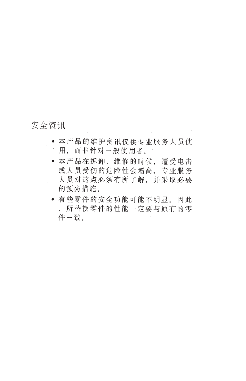
Error Indicator Table
Error
Code
64
65
66 to
78
No
Log
Alternating Light Pattern Action
Replace the EPROM and/or
system board.
Replace the EPROM and/or
system board.
Replace the EPROM and/or
system board.
79 Replace the EPROM and/or the
system board.
Diagnostic Information 5
Page 18
4076-0XX
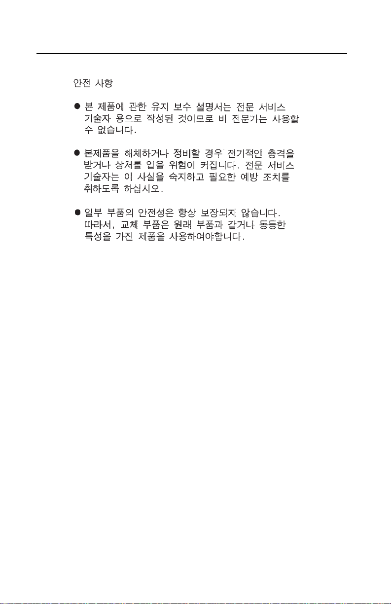
Error
Code
80 Go to the “Maintenance Station
81 Go to the “Transport Service
85 Go to the “Transport Service
Alternating Light Pattern Action
ServiceCheck”onpage12.
Check” on page 22.
Check” on page 22.
84 86
87 88
89 Go to the “Transport Service
Go to the “Simm Service Check”
on page 22.
Check” on page 22.
6
Page 19
4076-0XX
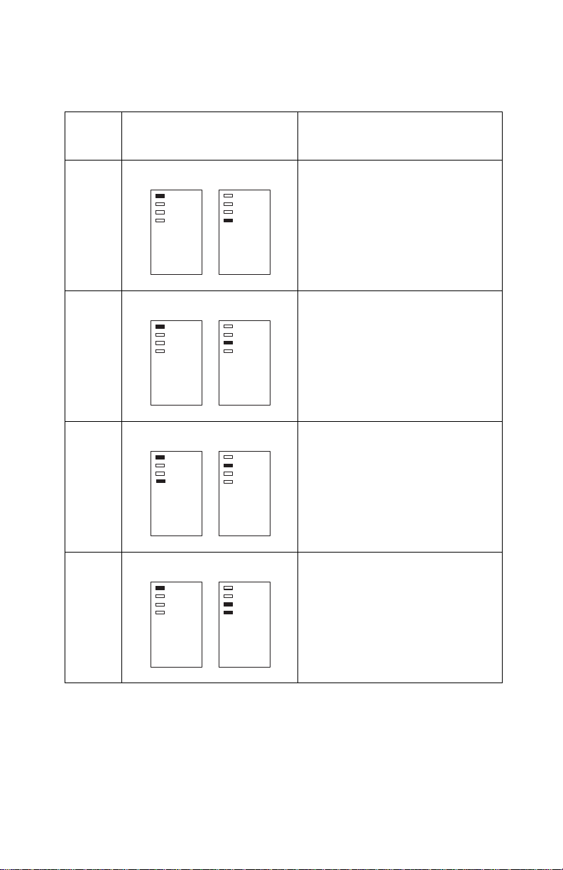
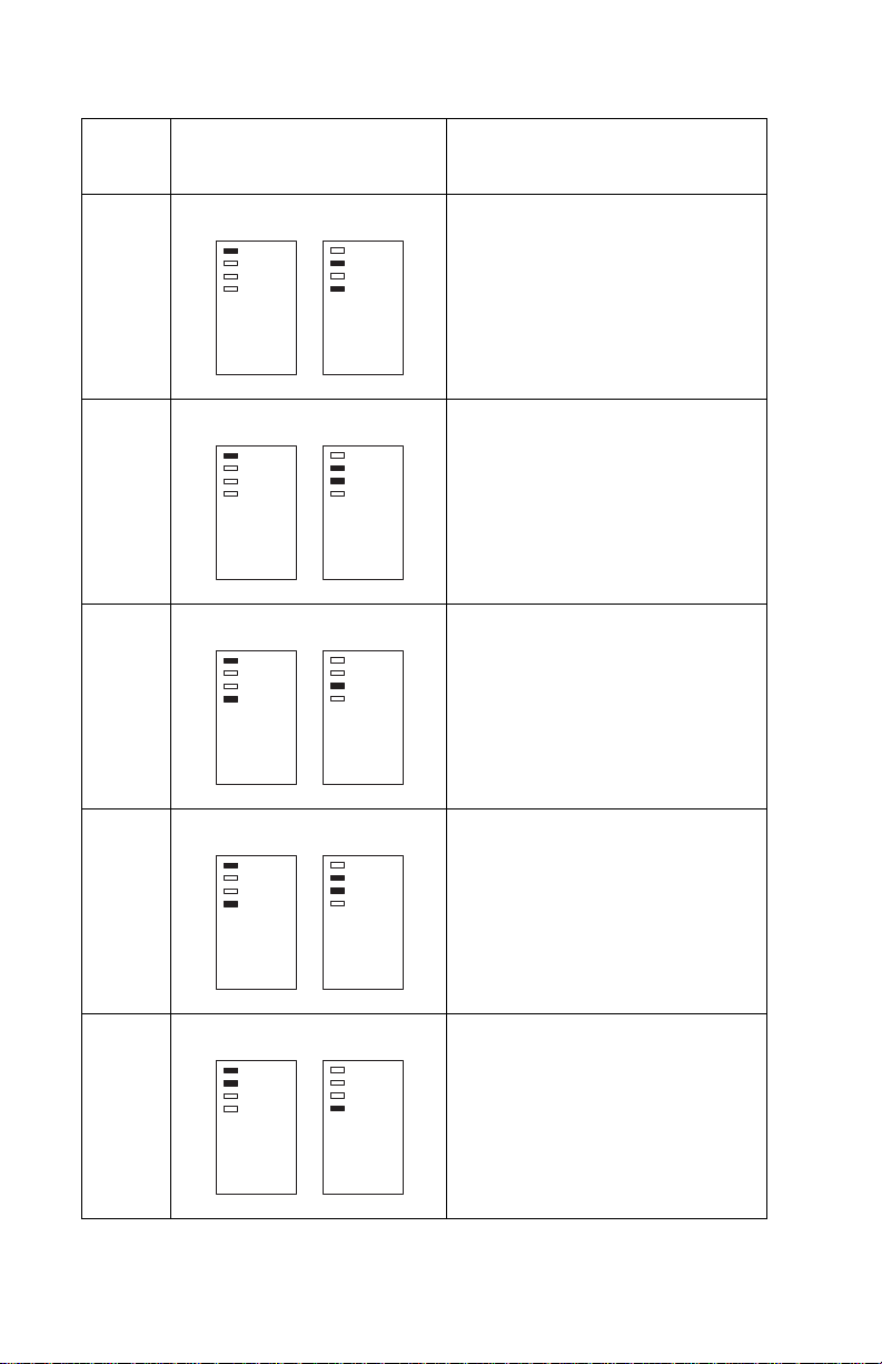
Error
Code
90 Go to the “Transport Service
127
and
up
Alternating Light Pattern Action
Check” on page 22.
Go to the “Maintenance Station
Service Check” on page 12.
Power-on-self-test (Post) Sequence
When you turn the printer on it performs a POST. Turn your machine
on and check for a correct POST operation by observing the following:
1. The power light comes on.
2. All four function lights come on and then go off one light at a time
starting with the Busy light. The Draft light may take longer than
the others to go off.
3. The paper feed gears turn.
4. The carrier moves to the left and right at least one time.
5. The maintenance station cleans and caps the print head.
6. All motors stop and the power light stays on.
If your machine completes POST with no errors, go to the. “Symp-
tom Tables” on page 9, locate your symptom and take the indicated
action.
If your machine does not complete POST locate your symptom in
the following table and take the indicated action
Diagnostic Information 7
Page 20

4076-0XX
POST Symptom Table.
Symptom Action
No lights come on and no motors run Go to the “Power Service
Check” on page 19.
The Powerlight is the only light that
comes on
One or more operator panel lights do
not come on
One or more operator panel lights do
not go off
Feeds paper Go to the “First Print Line Ser-
Paper feed gears do not turn Go to the “Paper Feed Service
Feeds paper and prints Go to the “ Note: if the failure
Carrier doesn’t move Go to the “Transport Service
Maintenance station doesn’t move Go to the “Maintenance Station
The printer prints “HARDWARE
ERROR HAVE PROTOCOL CONVERTER SERVICED”
The carrier moves then error 85
appears
Go to the “Operator Panel Ser-
vice Check” on page 13.
Go to the “Operator Panel Ser-
vice Check” on page 13.
Go to the “Operator Panel Ser-
vice Check” on page 13.
vice Check” on page 11.
Check” on page 14.
remains, replace the system
board” on page 12.
Check” on page 22.
ServiceCheck”onpage12.
Replace the serial adapter.
Replace the system board.
8
Page 21
4076-0XX
Symptom Tables
Locate your symptom in the following tables and take the appropriate action.
Carrier Transport Problems
SYMPTOM ACTION
• No carrier movement
• Slow carrier movement
• Carrier stops
Go to the “Transport Service Check”
on page 22.
Communications Problem
SYMPTOM ACTION
Printer not communicating with
host.
Go to the “Parallel Port Service
Check” on page 18.
Maintenance Station Problems
SYMPTOM ACTION
• Maintenance station doesn’t
move
• Failsto cap fails to cap the print
head the print head
• Fails to clean the print head
Go to the “Maintenance Station Ser-
vice Check” on page 12.
Operator Panel Problems
SYMPTOM ACTION
• Panel light(s) not working
• Panel button(s) not working
• Power Lights the only light that
comes on
• Panel cover closed, open functions not working
Go to the “ Note: if the failure
remains, replace the system board”
on page 12.
Diagnostic Information 9
Page 22

4076-0XX
Paper Feed Problems
SYMPTOM ACTION
Paper fails to stop at first print
line
• Fails to pick paper
• Picks more than one sheet of
paper
• Picks paper but fails to feed
• Paper jams
• Paper fails to exit
• Noisy paper feed
Envelopes fail to feed Go to the “Envelope Feed Service
Paper skews Go to the “Paper Path Service
Go to the “First Print Line Service
Check” on page 11.
Go to the “Paper Feed Service
Check” on page 14.
Check” on page 11.
Check” on page 17.
Power Problems
SYMPTOM ACTION
No power in machine, no lights,
no motors
Go to the “Power Service Check” on
page 19.
Print Quality Problems
SYMPTOM ACTION
• Voids in characters
•Lightprint
• Prints off the page
• Prints satellites
• Carrier moves but does not print
• Print head drying out prematurely
• Vertical alignment off
• Ink smearing
• Vertical streaks on paper
• Print lines crowded
Go to the “Print Quality Service
Check” on page 20.
Go to the “Paper Feed Service
Check” on page 14.
10
Page 23
4076-0XX
SIMM Problem
SYMPTOM ACTION
Can’t write to SIMM Go to the “Simm Service Check” on
page 22.
Service Checks
Envelope Feed Service Check
FRU OR PROCEDURE ACTION
1 Envelope Loading Be sure the envelope guides have
been turned to the envelope load
positions
Besuretheenvelopeguidesare
against the envelopes
Go to and perform the “Paper Feed
Service Check” on page 14.
First Print Line Service Check
FRU OR PROCEDURE ACTION
1 End-of-Forms Flag Check the flag for binds or damage.
2 End-of-Forms Sensor Check the sensor for dirt.
3 System Board Perform the “Paper Sensor Test” on
page 26 to check the end-of-forms sen-
sor.
4 Feed Arm Assembly Check all parts of the feed arm assem-
bly for binds, wear, or damage.
5 Software Setting Use Toolkit, on the setup diskette, to
6 Operator Panel Go to the “ Note: if the failure remains,
adjust the Top of Form setting.
replace the system board” on page 12.
Diagnostic Information 11
Page 24
4076-0XX
Maintenance Station Service Check
The maintenance station has two functions:
1. Cleans the print head nozzles during the print operation.
2. Seals the print head when it is not being used to prevent the nozzles from drying..
FRU OR PROCEDURE ACTION
1 Maintenance Drive Assem-
bly
2 System Board Turn the printer off and disconnect J4
3 Maintenance Rocker Am. Check for binds or wear.
4 Wiper A worn wiper will cause degraded print
Disconnect J4 from the system board.
Check for 18 ohms (±4 ohms) between
pins 1 and 2 at the motor. If the reading
is incorrect, replace the maintenance
drive assembly,
Check for motor pins shorted to the
motor housing. If you find a shorted pin,
replace the maintenance drive assembly. If the symptom remains, replace the
system board.
Abindinthedriveassemblycanprevent
the motor from turning. Check for binds
and loose or worn parts in the drive
assembly. Also check the motor gear
from the system board. Turn the printer
on and check for a pulse of 15 V dc
between J4-1 and ground on the system
board as the printer goes through
POST.
quality just after a maintenance cleaning. Check for loose or worn wiper.
5 Cap A worn cap will cause the print head
nozzles to dry and clog. Check for loose
or worn cap.
Note: if the failure remains, replace the system board
12
Page 25

4076-0XX
Operator Panel Service Check
FRU OR PROCEDURE ACTION
1 Power Supply Disconnect J11 from the system
board and check the following voltages on the power supply cable:
J11-1 to GND = +5V dc
J11-3 to GND = +24V dc
If you do not have correct voltage,
replace the power supply. Be sure to
unplug the machine before you reconnect the power supply to the system
board.
2 System Board Turn the printer on. Check for +5 V dc
at test point CE/TP near the operator
panel connector on the system board
3 Operator Panel Cover The operator panel cover actuates
the operator panel sensor on the
operator panel. Check the cover for
any broken parts. Check the operator
panel sensor for dirt.
4 Operator Panel Card
Operator Panel Cable
Check the operator panel cable for
continuity. If the cable is good,
replace the operator panel. If the
symptom remains, replace the system board.
Diagnostic Information 13
Page 26

4076-0XX
Paper Feed Service Check
If your machine does not have paper jam problems, go on to the service check. If your machine does have a paper jam problem, examine it for the following before you begin the service check.
• Check the entire paper path for obstructions.
• Make sure there is not too much paper in the ASF.
• Make sure the correct type of paper is in the machine.
• Check for static in the paper.
• Make sure the rear of the carrier guide is on top of the paper
guide.
FRU OR PROCEDURE ACTION
1 System Board With J5 disconnected and power on,
check for +24 V dc between J5-3 and
ground, and between J5-4 and
ground on the system board. If the
voltage is not present, check for
motor pins shorted to the motor housing. If you find a shorted pin, replace
the motor. If you still have a failure
after replacing the motor, replace the
system board.
14
Page 27
4076-0XX
FRU OR PROCEDURE ACTION
2 Paper Feed Motor Anoisy or chattering motor or a motor
that fails to turn, can be caused by:
• An open or short in the motor
• An open or short in the motor driver
on the system board
• Abind in the paper feed mechanism
Check for 100 ohms (±20 ohms)
between the following pins on the
motor:
Pin 1 to Pin 4
Pin 2 to Pin 4
Pin 3 to Pin 5
Pin 3 to Pin 6
If the readings are incorrect, replace
the motor. Check for motor pins
shorted to the motor housing. If you
find a shorted pin, replace the motor.
If the failure remains, replace the system board.
Although the paper feeds in a forward
direction only, the paper feed motor
turns in two directions. If the paper
feed motor turns in one direction only,
replace the system board. Binds in
thepaperfeedmotororgeartraincan
cause intermittent false paper jam
errors. Remove the paper feed motor
and check the shaft for binds Also
check for loose or worn motor gear
3 Gears Check for binds in the gear train and
paper feed mechanism. To do this,
rotate the largest gear by hand. If you
noticeabindisolateitbyremoving
thesmallidlergearontheoutsideof
the right side plate. Replace any worn
or binding gears, rollers, or bearings.
Diagnostic Information 15
Page 28

4076-0XX
FRU OR PROCEDURE ACTION
4 Feed Arm Assembly At the beginning of the paper feed
operation, the paper feed motor
reverses momentarily to allow the
feed arm pawl to drop off the home
position notch in the ASF side plate. If
the pawl fails to drop off the notch,
check the feed arm assembly for
binds, and worn or broken parts.
5 Auto Sheet Feeder Check the following for wear or dam-
age:
Pick Rollers
Envelope Bucklers
All parts inside the left and right edge
guides
6 End-of-Forms Flag Check for binds or damage.
7 Star Rollers Check for worn or binding rollers.
Check for broken star roller springs.
8 Ejectors After the paper exits from the exit roll-
ers, the paper feed motor reverses
causing the feed arm pawl to restore
tothehomepositionintheASFside
plate. At the same time, the paper
ejectors move the last sheet of paper
into the exit tray. If the ejectors do not
moveor restore, checkthem for worn,
loose, or broken parts.
16
Page 29
4076-0XX
Paper Path Service Check
Examine the machine for the following before you begin this service
check:
• Check the entire paper path for obstructions.
• Be sure the paper guides are not worn or broken and are posi-
tioned against the paper without binding or buckling the paper.
• Be sure the correct type of paper is in the machine.
• Be sure the rear of the carrier guide is on top of the paper guide.
FRU OR PROCEDURE ACTION
1 Large and Small Feed Roll-
ers
2 Large Feed Roller Springs Check for damage.
3 Auto Sheet Feeder Check the following for wear or dam-
4 End-of-Forms Flag Check for binds or damage.
5 ExitRoller Checkforwearorbinds.
6 Star Rollers Check for wear or binds. Check for
7 Ejectors After the paper exits from the exit roll-
Check for wear and binds.
age:
Envelope Bucklers
All parts inside the left and right edge
guides
broken star roller springs
ers, the paper feed motor reverses
causing the feed arm pawl to restore
tothehomepositionintheASFside
plate. At the same time, the paper
ejectors move the last sheet of paper
into the exit tray. If the ejectors do not
restore, check them for worn, loose,
or broken parts.
Diagnostic Information 17
Page 30

4076-0XX
Parallel Port Service Check
FRU OR PROCEDURE ACTION
1 Parallel Port Run a test page to be sure the printer
can print. Run the “Parallel Port Test”
on page 28. If the test fails, replace
the system board.
2 Serial Adapter Check the serial adapter green light.
If the light is off, replace the serial
adapter.
Run the “Serial Adapter Test” on
page 29. Compare the printout of the
switch setting configuration to the
switch settings on the serial adapter.
If they do not match, the switches
could be failing. Try running the Serial
Adapter Test again. If the printout still
doesn’t match the switchsettings,or if
you don’t get a printout replace the
serial adapter.
18
Page 31

4076-0XX
Power Service Check
FRU OR PROCEDURE ACTION
1 Power Supply Disconnect J11 from the system
board and check the following voltages on the power supply cable:
J11-1 to GND = +5V dc
J11-3 to GND = +24 V dc
If you do not have correct voltage,
replace the power supply. Be sure to
unplug the machine before you reconnect the power supply to the system
board.
2 Operator Panel With the power button depressed,
check for 0 ohms at J10-11 on the
front of the operator panel connector.
If the reading is incorrect, check the
operator panel cable for continuity. If
the cable has continuity, replace the
operator panel.
3 Print Head Cable
Simm Card
Parallel Cable
4 System Board If the symptom has not changed,
Turn off the printer. Disconnect one of
the listed components and turn on the
printer. Look for a symptom change.
Check the failing part for shorts and
replace as necessary. Repeat this
procedure for the remaining listed
parts.
replace the system board.
Diagnostic Information 19
Page 32

4076-0XX
Print Quality Service Check
FRU OR PROCEDURE ACTION
1 Print Cartr idge Be sure the machine has a known
good print cartridge.
2 Print Head Carrier Assembly Reseat the print head cable in the
3 Purge Test Perform the “Purge Test” on page 25.
system board and check the following
parts for wear or damage:
Print Cartridge Latch
Latch Spring
Carrier
Look for a break in the diagonal line
at the bottom of the test pattern. A
broken line indicates one or more
print nozzles are not working. Run the
test again to verify the failure If there
are even breaks in the diagonal line
similar to the pattern shown below,
replace the system board.
If there is a single break or random
breaks in the diagonal line check the
following:
• Print head cable - check the goldplated contacts on the end of the
cable that connects to the carrier for
dirt and wear. Use only a clean dry
cloth to clean the contacts. Also
check the cable for damage. You
mayneedtoremovethecablefrom
the carrier to inspect it.
• Rubber Backer - a worn rubber
backer will result in poor contact
between the print head cable and
the print cartridge. Check the rubber backer for wear
20
Page 33

4076-0XX
FRU OR PROCEDURE ACTION
4 Maintenance Station Intermittent nozzle failures can be
caused by worn parts in the maintenance station. Go to and perform the
“Maintenance Station Service Check”
on page 12, then return to this check.
5 Paper Feed Ink smudging and smearing can be
caused by paper problems or problems in the paper feed area. Check:
• Correct type of paper is in the
machine. Also check the paper for
curl and wrinkles.
• Feed roller for wear, dirt, or looseness
• Gears for wear or binds
• Paper path for obstructions
• Star rollers for binds or dirt. The exit
roller and star rollers keep tension
on the paper by moving slightly
faster than the feed rollers. A binding star roller can put vertical marks
on the paper.
6 Transport Blurred print and voids can be caused
by problems in the transport area.
Check the following:
• Transport belt for wear.
• Carrier guide and carrier guide rod
for wear or dirt.
• Idler pulley parts for wear, damage,
or looseness.
•Encoderstripforwearordirt.
7 BiDirectional Alignment Uneven vertical lines can be adjusted
by performing the “Bi-directional
Alignment Adjustment” on page 31.
Diagnostic Information 21
Page 34

4076-0XX
Simm Service Check
FRUU or PROCEDURE Action
1 SIMM Card Try the following:
1. Reseat the SIMM card.
2. Use Toolkit, on the setup diskette,
to format the SIMM card.
3. Try a known good SIMM card. If
the failure continues, replace the
system board.
Transport Service Check
FRU OR PROCEDURE ACTION
1 Transport Motor Check the motor for binds, or loose
motor pulley.
Disconnect the transport motor (J6)
from the system board. Check for 8 to
18 ohms between pins 1 and 2 on the
motor cable. If the reading is incorrect, replace the motor.
Check for motor pins shorted to the
motorhousing.Ifyoufindapin
shorted to the housing, replace the
motor. If the failure remains, replace
the system board.
2 System Board Turn the printer off and disconnect J6
from the system board. Turn the
printer on and check for a pulse of 3
to 5 V dc between J6-1 and ground
and between J6-2and ground on the
system board as the machine goes
through POST.
3 Transport Belt
Carrier Guide or Guide Rod
Idler Pulley Parts
Cable Clip
4 Encoder Strip Check for wear and dirt.
Check for worn, loose or broken
parts. Clean the carrier guide rod. Do
not lubricate the rod or the carrier rod
bearings. Check for obstructions
blocking carrier movement.
22
Page 35

4076-0XX
FRU OR PROCEDURE ACTION
5 Print Head Cable Be sure connector J1 is fully seated.
Check the cable for damage.
6 Encoder Strip
Print Head Cable,
System Board
7 Maintenance Station A problem with the maintenance sta-
Perform the “Encoder Sensor Test” on
page 27. If you cannot enter the test,
replace the system board.
tion can cause carrier movement
problems at the right margin. Go to
the “Maintenance Station Service
Check” on page 12.
Diagnostic Information 23
Page 36

4076-0XX
Diagnostic Aids 4
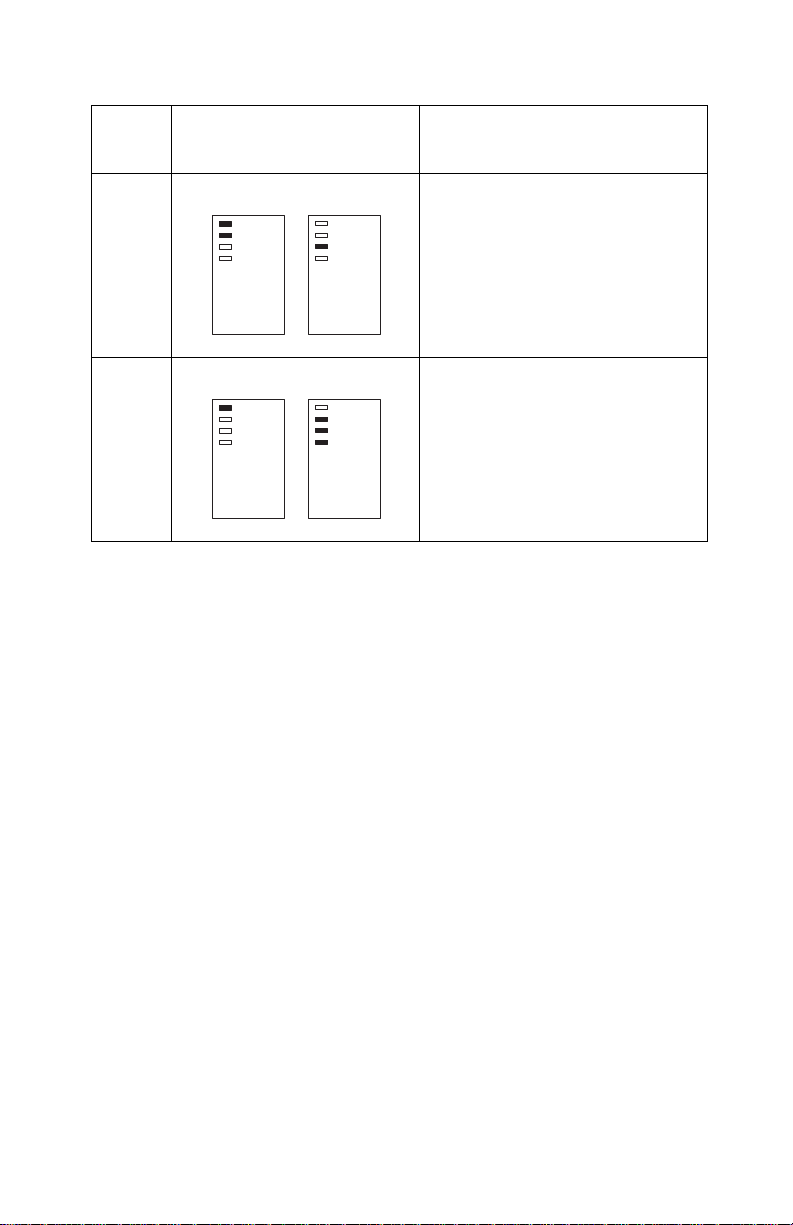
Use these diagnostic test procedures to verify a repair. The test procedures are entered by pressing and holding a button, or buttons,as
you turn on the printer. Except for the Hex Print test procedure, the
printer does not need to be attached to a host to run the tests. You
can press the buttons with the operator panel cover open or closed.
You must hold the buttons until all the lights are off. To terminate a
test press the Reset button, or turn the printer off. The button pattern
is illustrated for each test. Press the buttons that are shaded.
Demo Test
Perform this test with a black print cartridge installed.
This test prints a two-page demo pattern. Use this test to check the
overall quality of line print and graphics.
Print Fonts Test
Perform this test with a black print cartridge installed.
This test prints a sample of each font installed in the printer. This
includes resident fonts and fonts stored in FLASH memory. Fonts
downloaded to RAM cannot be printed with this test because the
power off/on sequence deletes all RAM fonts. This test also lists the
emulation mode and the installed options.
Diagnostic Aids 24
Page 37

4076-0XX
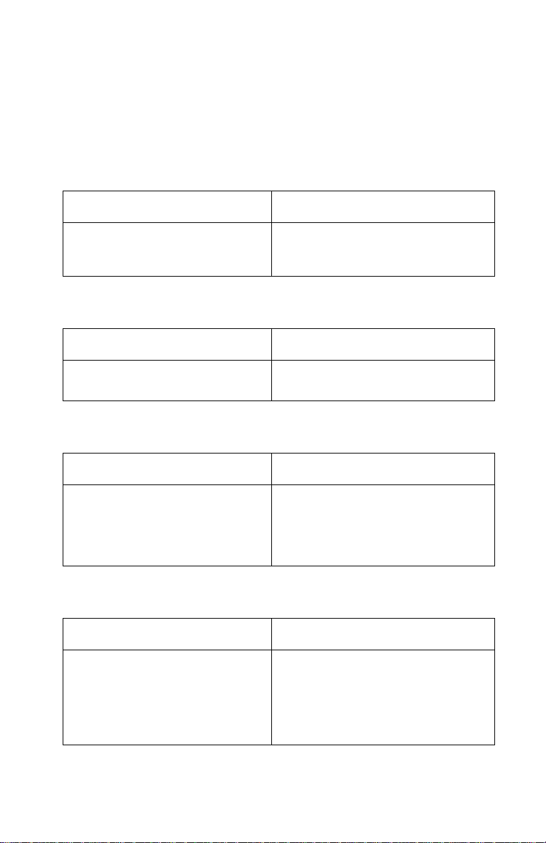
Purge Test
Perform this test with a black print cartridge installed.
This test prints out a nozzle test pattern followed by several grey
lines and another nozzle test pattern. Use this test to check the function of all the nozzles in the print cartridge. This test also checks the
electronic connection to the print cartridge. D uring the test, the print
cartridge head goes through a maintenance cleaning at the maintenance station.
Running this test with a color print cartridge installed will clear the
nozzles in the cartr idge.
Print Nvram
Perform this test with a black print cartridge installed. In addition to
holding down the buttons, ExecJet IIc requires that youplace a piece
of paper in the manual feed slot to push the EOF flag out of the sensor.
This test prints the contents of NVRAM.
Diagnostic Aids 25
Page 38

4076-0XX
Test Page
Perform this test with a black print cartridge installed.
This test repeatedly prints the nozzle test pattern followed by a sample of each font installed in the printer including resident fonts as well
as fonts stored in FLASH memory. This test continues until you
press the Reset button or turn off the printer.The error number is the
last number to print on the page in the lower right corner.
Paper Sensor Test
Release the buttons after the maintenance station uncaps the print
head.
In the paper sensor mode, the draft light displays the status of the
paper sensor (On=paper not present). Check the paper sensor by
either activating the end-of-forms flag or by placing a piece of paper
in the paper sensor. The draft light goes on and off as you move the
flag past the sensor. If the test fails, replace the system board.
26
Page 39

4076-0XX
Encoder Sensor Test
Release the button after the maintenance station uncaps the print
head.
For this test the bottom three operator panel lights display the current carrier position as determined by the carrier encoder. The
printer motors are disabled during this test to allow you to manually
move the carrier to verify the encoder is working correctly. The bottom 3 lights will repeat a count of 0 to 7 as you move the carrier
across the machine with the Ink Low Light = 1, the Paper Out Light =
2, and the Busy Light = 4.
If the lights do not change, replace the print head cable.If the lights
appear to have a break in the sequence, replace the encoder strip.If
the bottom 3 lights do not come on, replace the print head cable. If
the symptom remains, replace the system board.
Hex Print
Perform this test with a black print cartridge installed.
Use this test to put the printer in hex mode. The printer prints in
hexadecimal instead of ASCII.
Diagnostic Aids 27
Page 40

4076-0XX
Parallel Port Test
This test requires a parallel port wrap plug. Install the wrap plug in
the parallel port before you start the test. This test performs a wraparound test between the pr inter parallel port and the parallel port
test connector.If the test is successful, the top two lights and bottom
two lights blink alternately. If the test is not successful, only the bottom two lights will blink.
Initialize Nvram
Use this procedure to reset the error log portion of NVRAM. The
paper sensor must be open to perform this function. To do this, place
a piece of paper in the manual paper feed slot before you turn the
machine on. Except for bi-directional alignment settings, all user settings and defaults will not be reset. Resetting the error log allows you
to track new errors. The error log is especially helpful in diagnosing
intermittent or difficult problems. Check the bi-directional alignment
after you do this procedure.
28
Page 41

4076-0XX
Serial Adapter Test
Perform this test with a black print cartridge installed.
This test checks out the connection between the serial adapter and
the printer. To run the test:
1. Turn the machine off.
2. Set switch 10 on the serial adapter card to ON.
3. Turn the machine on to print out the current switch settings and a
test pattern.
4. You may have to press Forms Feed to print the test.
Diagnostic Aids 29
Page 42

4076-0XX
Repair Information 5
This chapter explains how to make adjustments to the printer and
how to remove defective parts.
WARNING: Read the following before handling electronic parts.
Handling Esd-sensitive Parts
Many electronic products use parts that are known to be sensitive to
electrostatic discharge (ESD). To prevent damage to ESD-sensitive
parts, follow the instructions below in addition to all the usual precautions, such as turning off power before removing logic boards:
• Keep the ESD-sensitive part in its original shipping container (a
special “ESD bag”) until you are ready to install the part into the
machine.
• Make the least-possible movements with your body to prevent an
increase of static electricity from clothing fibers, carpets, and
furniture.
• Put the ESD wrist strap on your wrist. Connect the wrist band to
the system ground point. This discharges any static electricity in
your body to the machine.
• Hold the ESD-sensitive part by its edge connector shroud
(cover); do not touch its pins. If you are r emoving a pluggable
module, use the correct tool.
• Do not place the ESD-sensitive part on the machine cover or on
a metal table; if you need to put down the ESD-sensitive part for
any reason, first put it into its special bag.
• Machine covers and metal tables are electrical grounds. They
increase the risk of damage because they make a discharge
path from your body through the ESD-sensitive part. (Large
metal objects can be discharge paths without being grounded.)
• Prevent ESD-sensitive parts from being accidentally touched by
other personnel. Install machine covers when you are not working on the machine, and do not put unprotected ESD-sensitive
parts on a table.
• If possible, keep all ESD-sensitive parts in a grounded metal
cabinet (case).
Repair Information 30
Page 43

4076-0XX
• Be extra careful in working w ith ESD-sensitive parts when cold-
weather heating is used because low humidity increases static
electricity.
Adjustments
Bi-directional Alignment Adjustment
Perform this adjustment with the black print cartridge installed.
1. Turn off the printer.
2. Hold down the Install Print Cartridge button and the Line Feed
Button, then turn on the printer. Release the buttons when all the
lights go out.
3. A page loads and the bi-directional alignment pattern prints. The
pattern consists of three lines of vertical bars. The bars are
aligned when the adjustment is correct. The following sample
requires the center vertical bars to be moved to the right.
4. The center bars can be coarse aligned or fine aligned. Coarse
alignment moves the center bar 1/300” (.085mm). Fine alignment moves the center bar 1/1200” (.021mm). To perform the
coarse alignment, open the operator panel coverand use the top
two buttons to move the center bar. Press the left button to move
the bar to the left. Press the right button to move the bar to the
right. Each time you press the button the three lines will print.
5. To fine align the bars, close the operator panel cover and use the
two bottom buttons. Press the left button to move the center bar
to the left. Press the right button to move the bar to the right.
Each time you press a button the three lines will print.
6. When the alignment is correct, press the Draft button to switch to
the draft mode. Followthe same procedure as aboveto align the
bars in the draft mode.
7. When you complete the adjustment and turn off the printer the
settings will be saved in NVRAM.
Repair Information 31
Page 44

4076-0XX
Removal Procedures
The following procedures are arranged in alphabetical order according to the name of the printer part discussed. When there is artwork
to support a procedure, it follows the text.
Releasing Plastic Latches
Many of the parts are held in place with plastic latches. To remove
such parts, press the hook end of the latch away from the part to
which it is latched. The latches break easily. Release them carefully.
Never apply excessive force
Hook
when releasing the hook.
32
Page 45

4076-0XX
Auto Sheet Feed (ASF) Assembly Removal
1. Remove the top cover.
2. Push in the two latches [ A] that secure the auto sheet feed to the
side frame, then lift up the auto sheet feed to remove it from the
machine.
A
A
When you reinstall the auto sheet feed, be sure the feed arm assembly is vertical, with the feed pawl at the top.
ASF Envelope Buckler And Pick Roller Hub Removal
1. Remove the ASF.
2. Remove the inside C-clip from the pick roller shaft and pull the
shaft to the right far enough to remove the envelope bucklers
and pick rollers.
3. Remove the pick roller hubs from the bucklers.
Repair Information 33
Page 46

4076-0XX
ASF Right And Left Edge Guide Assemblies Removal
1. Remove the auto sheet feed.
2. Remove the manual insert tray by prying one of the side frames
away from it.
3. Remove the inside C-clip from the pick roller shaft and pull the
shaft out to the right.
4. Remove the pick roller and buckler assemblies.
5. Remove the paper load lever knob from the load lever.
6. Remove the auto sheet feed right side cover by prying up at the
slots in the rear.
7. Remove the paper load lever and shaft by pulling them out from
the right side of the ASF assembly. Be careful not to lose the
small gear on the left end of the shaft. When you reinstall this
shaft, it must be parallel with the ASF housing.
8. Pivot the guide assembly up and pry it off the back plate.
ASF Paper Load Lever Removal
1. Remove the auto sheet feed assembly.
2. Pull the paper load lever knob from the load lever.
3. Remove the auto sheet feed right side cover by prying up the
slots in the rear.
4. Remove the paper load lever from the mounting stud.
Carrier Removal
1. Remove the top cover.
2. Remove the print cartridge.
3. Disconnect the print head cables from the system board. You
mayhave to open the print head cable connectors on the system
board first, then disconnect the cables.
4. Move the carrier in line with the opening in the carrier transport
motor frame.
5. Reach through the opening and pull the belt from the carrier.
6. To unlock the carrier guide rod latches, rotate the rod top-to-rear.
Gently push the carrier guide rod latches, at each end of the rod,
to the rear and lift up the rod until the sensor on the carrier clears
the encoder strip. Remove the carrier guide rod through the
opening in the left side frame. Be careful not to damage the
encoder strip.
7. Pull the ends of the print head cables into the machine, then
remove the cables from the 4 r etainers in the paper guide
starting from the right.
34
Page 47

4076-0XX
Carrier Transport Belt Removal
1. Remove the top cover.
2. Move the carrier in line with the opening in the carrier transport
motor frame.
3. Reach through the opening and pull the belt from the carrier.
4. Remove the belt from the carrier transport motor pulley.
5. Remove the belt from the idler pulley and pull it through the
opening in the left side frame.
Note: When you reinstall the belt be sure to insert the bottom of
the belt into BOTH the lower and upper belt grips on the carrier.
DO NOT INSERT THE TOP OF THE BELT INTOTHE TOP GRIP.
Carrier Guide Removal
You may remove the carrier guide without removing the covers if you
carefully follow this procedure.
1. Open and remove the access cover.
2. Remove the print cartridge.
3. With the carrier centered, carefully release the 2 carrier guide
rod latches and lift the shaft slightly.
4. Unlatch the 2 carrier guide latches by pushing to the rear.
5. Gently push the carrier to the extreme right and remove the carrier guide.
When you reinstall the carrier guide, be sure the fingers on the bottom of the carrier engage the groove on the carrier guide before you
snap the carrier guide rod down.
Carrier Transport Motor Removal
1. Remove the top cover.
2. Disconnect the carrier transport motor (J6) from the system
board.
3. Remove the 2 motor mounting screws and remove the motor.
Repair Information 35
Page 48

4076-0XX
Carrier Transport Motor Frame Removal
1. Remove the top cover.
2. Disconnect J6 from the system board.
3. Move the carrier in line with the opening in the carrier transport
motor frame.
4. Reach through the opening and pull the belt from the carrier.
5. To unlock the carrier guide rod latches, rotate the rod top-to-rear.
Gently push the carrier guide rod latches, at each end of the rod,
to the rear and lift up the rod until the sensor on the carrier clears
the encoder strip. Remove the carrier guide rod through the
opening in the left side frame. Be careful not to damage the
encoder strip.
6. A latch on the top front end of each side frame holds the transport motor frame in place. Push up the latches on the front of the
side frames and pivot the carrier transport motor frame down
and out of the side frames.
Encoder Strip Removal
1. Remove the top cover.
2. Move the carrier in line with the opening on the carrier transport
motor frame.
3. Reach through the opening and pull the belt from the carrier.
4. To unlock the carrier guide rod latches, rotate the rod top-to-rear.
Gently push the carrier guide rod latches at each end of the rod
to the rear and lift up the rod until the sensor on the carrier clears
the encoder strip. Place the carrier on top of the paper guide.
5. Remove the encoder strip from the left mounting peg. To do this,
push the right latch slightly to the left.
6. Remove the encoder strip from the right latch.
When you install the encoder strip, be sure it is fully seated on the
left mounting peg.
36
Page 49

4076-0XX
End-of-forms Flag Removal
1. Remove the top cover.
2. Remove the ASF.
3. Disconnect the print head cables from the system board. You
mayhave to open the print head cable connectors on the system
board first, then disconnect the cables
4. Disconnect connectors J4, J5, and J6 from the system board. 5.
Remove the machine from the base. To do this, unlatch the 4
base frame latches. Lift the machine from the base and set it on
its front with the bottom facing you.
5. Pivot the weighted end of the end-of-forms flag through the
opening in the middle frame.
6. Lift the flag up and out of the machine.
Exit Roller Assembly Removal
1. Remove the top cover.
2. Remove the carrier transport frame.
3. Pivot the paper ejector pusher toward the front then pull it to
remove the paper ejector from the shaft.
4. Removethe bushing from the left end of the exit shaft. To do this,
pull the tab and rotate the bushing.
5. Slide the exit roller to the left and lift it out of the machine.
Eprom Removal
1. Remove the top cover.
2. Disconnect the print head cables from the system board. You
mayhave to open the print head cable connectors on the system
board first, then disconnect the cables.
3. Disconnect connectors J4, J5, and J6 from the system board.
4. Remove the machine from the base. To do this, push the frame
latches out as you lift the machine from the base. Set the
machine aside.
5. Gently pry the EPROM from the system board.
Feed Arm Assembly Removal
1. Remove the top cover.
2. Remove the auto sheet feed.
3. Remove the C-clip from the center of the large gear and remove
the feed arm assembly.
Repair Information 37
Page 50

4076-0XX
Inside Idler Gears Removal
1. Remove the top cover.
2. Remove the auto sheet feed.
3. Disconnect the print head cables from the system board. You
mayhave to open the print head cable connectors on the system
board first, then disconnect the cables.
4. Remove the paper guide.
5. Remove the C-clip from the feed arm assembly and remove the
feed arm assembly.
6. Pull the idler gears off the mounting studs.
Large Feed Roller Assembly Removal
1. Remove the top cover.
2. Disconnect the print head cables from the system board. You
mayhave to open the print head cable connectors on the system
board first, then disconnect the cables.
3. Disconnect connectors J4, J5, and J6 from the system board. 4.
Remove the machine from the base. To do this, push the frame
latches out as you lift the machine from the base. Set the
machine aside.
4. Place the machine on its front with the bottom facing you.
5. Disconnect the 3 springs from the bottom of the middle frame
assembly.
6. Remove the large feed roller assembly.
38
Page 51

4076-0XX
Left Side Frame Removal
1. Remove the top cover.
2. Remove the print cartridge.
3. Remove the auto sheet feed.
4. Disconnect the print head cables from the system board. You
mayhave to open the print head cable connectors on the system
board first, then disconnect the cables.
5. Disconnect connectors J4, J5, and J6 from the system board.
6. Remove the machine from the base. To do this, push the frame
latches out as you lift the machine from the base. Set the
machine aside.
7. Move the carrier in line with the opening in the carrier transport
motor frame.
8. Reach through the opening and pull the belt from the carrier.
9. To unlock the carrier guide rod latches, rotate the rod top-to-rear.
Gently push the carrier guide rod latches, at each end of the rod,
to the rear and lift up the rod until the sensor on the carrier clears
the encoder strip. Remove the carrier guide rod through the
opening in the left side frame. Be careful not to damage the
encoder strip.
10. Pull the ends of the print head cables into the machine, then
remove the cables from the 4 retainers in the paper guide starting from the right.
11. Disengage the left paper guide latch by carefully moving the rear
of the left side frame to the left.
12. Disengage the right side of the paper guide from the latch and lift
it from the machine.
13. A latch on the top front end of each side frame holds the transport motor frame in place. Push up the latches on the front of the
side frames, then pivot the carrier transport motor frame down
and out of the side frames.
14. Place the machine on its back and push the left side frame latch
to the rear and remove the frame from the machine.
When you reinstall the paper guide, be sure the front edge goes
under the rear of the carrier guide. If the paper guide is on top of the
carrier guide, push down the front, bottom edge. It will snap under
the carrier guide.
Repair Information 39
Page 52

4076-0XX
To install the left side frame onto the middle frame, align the right
side frame latch with the latching surface on the middle frame before
you align the roller shafts and carrier guide. It may be easier to do
this with the machine on its right side.
Maintenance Drive And Rocker Assemblies Removal
1. Remove the top cover.
2. Remove the auto sheet feed.
3. Remove the right side frame.
4. Gently unlatch the maintenance assembly latches, and slide out
the maintenance drive assembly, then the rocker assembly.
When you reassemble the drive assembly, be sure the forks engage
the pins on the rocker assembly.
Middle Frame Removal
1. Remove the top cover.
2. Remove the print cartridge.
3. Remove the auto sheet feed.
4. Disconnect the print head cables from the system board. You
mayhave to open the print head cable connectors on the system
board first, then disconnect the cables.
5. Disconnect J4, J5, and J6 from the system board.
6. Remove the machine from the base. To do this, unlatch the 4
base frame latches. Lift the machine from the base and set it
aside.
7. Remove the paper ejectors from the middle frame.
8. Remove the left side frame.
9. Remove the exit shaft.
10. Remove the small feed roller shaft.
11. Remove the large feed roller shaft and springs.
12. Remove the end-of-forms flag.
13. Remove the right side frame.
14. Remove the maintenance station.
Operator Panel Removal
1. Remove the top cover.
2. Remove the 3 operator panel mounting screws.
3. Remove the operator panel.
40
Page 53

4076-0XX
Outside Idler Gears Removal
1. Remove the top cover.
2. Disconnect the print head cables from the system board. You
mayhave to open the print head cable connectors on the system
board first, then disconnect the cables.
3. Each gear is latched in place. Push up the latch and remove the
gear from the side frame stud by pulling the gear from the bottom.
Paper Ejectors Removal
1. Remove the top cover.
2. Pivot the paper ejector pusher toward the front then pull it to
remove the paper ejector from the shaft.
3. Unsnap the paper ejectors from the middle frame.
Paper Feed Motor Removal
1. Remove the top cover.
2. Disconnect the paper feed motor from the system board.
3. Removethe two mounting screws or rotate the paper feed motor
counter-clockwise to remove it from the right side frame.
Paper Guide Removal
1. Remove the top cover.
2. Remove the auto sheet feed.
3. Disconnect the print head cables from the system board. You
mayhave to open the print head cable connectors on the system
board first, then disconnect the cables.
4. Pull the ends of the print head cables into the machine, then
remove the cables from the 4 retainers in the paper guide starting from the right.
5. Disengage the left paper guide latch by c arefully movingthe rear
of the left side frame to the left.
6. Disengage the right side of the paper guide from the latch and lift
it from the machine.
Note: When you reinstall the paper guide, be sure the front edge
goes under the rear of the carrier guide. If the paper guide is on top
of the carrier guide, push down the front, bottom edge. It will snap
under the carrier guide.
Repair Information 41
Page 54

4076-0XX
Paper Release Lever Removal
1. Remove the top cover.
2. Pull the paper release lever forward.
3. Place a screw driver into the slot [A] of the paper release lever.
Push the screw driver down to release the latch, then remove
the lever.
A
Power Supply Removal
1. Remove the top cover.
2. Disconnect the print head cables from the system board. You
mayhave to open the print head cable connectors on the system
board first, then disconnect the cables.
3. Disconnect connectors J4, J5, and J6 from the system board.
4. Remove the machine from the base. To do this, push the frame
latches out as you lift the machine from the base. Set the
machine aside.
5. Disconnect the power supply cable from the system board.
6. Remove the 4 power supply mounting screws and remove the
power supply.
NOTE: The fuse on the power supply is for safety pur- poses only. If
it blows, there is a bad component on the board. Do not replace the
fuse. A new fuse will not correct the failure.
42
Page 55

4076-0XX
Print Head Cable Removal
1. Remove the top cover.
2. Remove the print cartridge.
3. Remove the carrier.
4. Remove the cable clip [A] from the left side of the carrier.
5. Remove the pointer from the front of the carrier.
A
6. Remove the 2 sensor mounting screws.
7. Push down the 2 latches that secure the cradle to the carrier and
pull the cradle up from the carrier.
8. Remove the print head cable from the alignment pins.
The new cable comes without the folds in it. Place the new cable
next to the old cable and fold the new cable in the appropriate
places.
Repair Information 43
Page 56

4076-0XX
Right Side Frame Removal
1. Remove the top cover.
2. Remove the print cartridge.
3. Remove the auto sheet feed.
4. Disconnect the print head cables from the system board. You
mayhave to open the print head cable connectors on the system
board first, then disconnect the cables.
5. Disconnect connectors J4, J5, and J6 from the system board.
6. Remove the machine from the base. To do this, push the frame
latches out as you lift the machine from the base. Set the
machine aside.
7. Move the carrier in line with the opening in the carrier transport
motor frame.
8. Reach through the opening and pull the belt from the carrier.
9. To unlock the carrier guide rod latches, rotate the rod top-to-rear.
Gently push the carrier rod guide latches, at each end of the rod,
to the rear and lift up the rod until the sensor on the carrier clears
the encoder strip. Remove the carrier rod guide through the
opening in the left side frame. Be careful not to damage the
encoder strip.
10. Pull the ends of the print head cables into the machine, then
remove the cables from the 4 retainers in the paper guide starting from the right.
11. Disengage the left paper guide latch by carefully moving the rear
of the left side frame to the left.
12. Disengage the right side of the paper guide from the latch and lift
the guide from the machine.
13. A latch on the top front end of each side frame holds the transport motor frame in place. Push up the latches on the front of the
side frames, then pivot the carrier transport motor frame down
and out of the side frames.
14. Place the machine on its back, then unlatch the right frame latch
from the middle frame and remove the side frame.
NOTE:for reassembly you may want to remove the carrier guide and
reinstall it after you install the paper guide.
When you reinstall the paper guide, be sure the front edge goes
under the rear of the carrier guide. If the paper guide is on top of the
44
Page 57

4076-0XX
carrier guide, push down the front, bottom edge. It will snap under
the carrier guide.
To install the right side frame onto the middle frame, align the right
side frame latch with the latching surface on the mid frame before
you align the roller shafts and carrier guide. It may be easier to do
this with the machine on its left side.
Rubber Backer Removal
1. Remove the top cover.
2. Remove the print cartridge.
3. Remove the print head cable.
4. Remove the rubber backer from the carrier.
Small Feed Roller Assembly Removal
1. Remove the top cover.
2. Remove the auto sheet feed.
3. Remove the paper guide
4. Carefully remove the paper release lever.
5. Remove the bushing from the left end of the small feed roller
shaft. To do this, pull the tab and rotate the bushing.
6. Slide the small feed roller assembly to the left and lift it out of the
machine.
Star Roller Removal
1. Remove the top cover.
2. Move the carrier in line with the opening on the carrier transport
motor frame.
3. Reach through the opening and pull the belt from the carrier.
4. To unlock the carrier guide rod latches, rotate the rod top-to-rear.
Gently push the carrier guide rod latches at each end of the rod
to the rear and lift up the rod until the sensor on the carrier clears
the encoder strip. Place the carrier on top of the paper guide.
5. A latch on the top front end of each side frame holds the transport motor frame in place. Push up the latches on the front of the
side frames and pivot the carrier transport motor frame down
and out of the side frames. Place the carrier transport motor
frame face down in front of the machine.
6. Removethe star roller by pushing it forward off the mounting peg
in the carrier transport motor frame.
Repair Information 45
Page 58

4076-0XX
System Board Removal
1. Remove the top cover.
2. Disconnect the print head cables from the system board. You
mayhave to open the print head cable connectors on the system
board first, then disconnect the cables.
3. Disconnect connectors J4, J5, and J6 from the system board. 4.
Remove the machine from the base. To do this, push the frame
latches out as you lift the machine from the base. Set the
machine aside.
4. Disconnect the power supply cable from the system board.
5. Remove the 6 system board mounting screws and remove the
system board.
6. Check the bi-directional alignment adjustment.
After replacing the system board, reset the printer to the factory
defaults as follows:
For countries using 8.5 x 11 paper:
1. Turn off the printer.
2. Hold down the Form Feed, Line Feed, and Install Ink Cartridge
buttons and turn on the printer. Continue to hold down the buttons until all the lights are off.
3. Check the bi-directional alignment.
For countries using A4 paper:
1. Turn off the printer.
2. Place a piece of paper in the manual feed slot to push the EOF
flag out of the sensor.
3. Holddown the Install Print Cartridge, Form Feedand Draft/Letter
Quality buttons and turn on the printer. Continue to hold down
the buttons until all the lights are off.
4. Check the bi-directional alignment.
46
Page 59

4076-0XX
Top Cover Removal
1. Unplug the power cord and the interface cable from the back of
the printer.
2. Pull up the tab latch on the print cartridge storage unit and
remove the unit from the machine.
3. Unlatch the auto sheet feed left cover by pushing it up from the
bottom, then slide it off the machine.
4. Turn the machine around to remove the rear cover. Remove the
screw and washer from the rear cover. Place a screwdriver in the
left slot [A] and push the latch down. At the same time push the
right latch [A]down.
A
A
5. Pull the rear cover out until the latches clear the top cover, then
lift the cover off the base.
6. Turn the machine to the front and pull the paper tray forward.
7. Pull the top cover forward until it stops. Be sure the paper
release lever clears the slot in the top cover. The operator panel
cable is still connected, so carefully lift the cover off the base.
8. Set the cover down in front of the machine.
9. Pull the operator panel cable from the connector on the system
board.
NOTE: When you reinstall the top cover, pull out the exit tray to prevent it from being trapped under the cover.
Repair Information 47
Page 60
4076-0XX
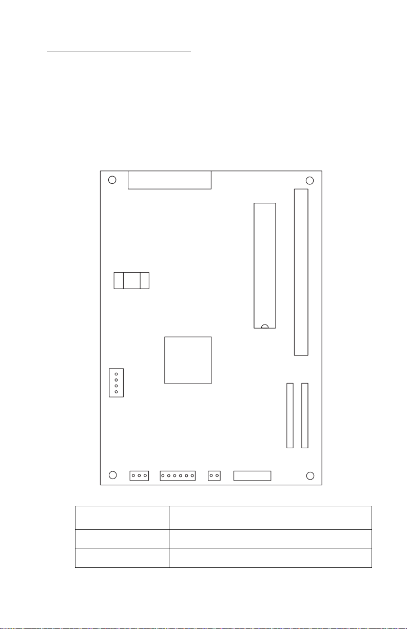
Connector Locations 10
This chapter shows the locations of major printer assemblies, connectors, and ground straps.
System Board Connectors
J9
S1
U23
1
J11
J6
1
J5
J4
1
1
U20
J7
J1
1
J10
1
.CE/TP
1
1
J2
Connector Connector Names
J1 Print Head Cable
J2
Print Head Cable
Connector Locations 48
Page 61

4076-0XX
Connector Connector Names
J4
J5
J6
J7
J9
J10
J11
U20
Maintenance Motor
Paper Feed Motor
Transport Motor
FLASH/RAM SIMM Option
Parallel Port
Operator Panel
PowerSupply
Code Module
Connector Locations 49
Page 62

4076-0XX
Preventive Maintenance 11
This chapter contains the lubrication specifications. Following these
recommendations can help prevent problems and maintain optimum
performance.
Lubrication Specifications
Lubricate only when parts are replaced or as needed, not on a
scheduled basis. Use no. 23 grease to lubricate the following:
• All gear mounting studs
• The right end of the exit roller at the right side frame
• The right end of the small feed roller at the right side frame
• The left end of the large feed roller at the left side frame
• Both ends of the ASF pick roll shaft at the ASF side frames
• Transport belt idler pulley hole
• Inside surface of the transport idler pulley tension wedge where it
touches the left side frame.
Do not lubricate the carrier guide rod orcarrier guide rod bearings.
Preventive Maintenance 50
Page 63

4076-0XX
Parts Catalog 12
How To Use This Parts Catalog
• SIMILAR ASSEMBLIES: If two assemblies contain a major-
ity of identical parts, they are broken down on the same list.
Common parts are shown by one index number. Parts
peculiar to one or the other of the assemblies are listed separately and identified by description.
• AR: (As Required) in the Units column indicates that the
quantity is not the same for all machines.
• NP: (Non-Procurable) in the Units column indicates that the
part is non-procurable and that the individual parts or the
next higher assembly should be ordered.
• NR: (Not Recommended) in the Units column indicates that
the part is procurable but not recommended for field
replacement, and that the next higher assembly should be
ordered.
• R: (Restricted) in the Units column indicates that the part
has a restricted availability.
• NS: (Not Shown) in the Asm-Index column indicates that
the part is procurable but is not pictured in the illustration.
• INDENTURE: The indenture is marked by a series of dots
located before the parts description. The indenture indicates the relationship of a part to the next higher assembly.
For example:
INDENTURE RELATIONSHIP OF PARTS
(No dot) MAIN ASSEMBLY
(One dot) o Detail parts of a main assembly
(One dot) o Subassembly of the main assembly
(Two dot) o o Detail part of a one-dot subassembly
(Two dot) o o Subassembly of a one-dot subassembly
51
Page 64

4076-0XX
7
8
Assembly 1: Covers
2
6
9
4
52
5
1
3
Page 65

4076-0XX
Asm. 1
Index
1 1367099 1 Top Cover
2 1367487 1 Access Cover Asm
3 1367486 1 Font Card Door
4 1367479 1 Rear Cover
5 1367493 1 Left Output Guide
6 1367484 1 Logo, ExecJet II
6 1375486 1 Logo, ExecJet IIc
7 1 Screw, Parts Packet 1367169
8 1 Washer, Parts Packet1367169
9 1425698 1 Print Cartridge Storage Unit,
Part
Number
Units Description
ExecJet IIc
53
Page 66

4076-0XX
Assembly 2: Frames
2
5
7
3
4
54
1
6
Page 67

4076-0XX
Asm. 2
Index
1 1367489 1 Base Asm
2 1367209 1 Left Side Frame
3 1374349 1 Middle Frame Asm
4 1367229 1 Right Side Frame
5 1367309 1 Carrier Transport Motor Frame
6 1367199 1 Exit Tray Asm
7 1367079 1 Carrier Guide
Part
Number
Units Description
55
Page 68

4076-0XX
Assembly 3: Paper Feed
1
2
5
3
4
56
6
7
8
9
Page 69

4076-0XX
Asm. 3
Index
1 1367179 1 PaperRelease Lever
2 2 Bushing, Parts Packet 1367169
3 1367339 1 PaperGuide
4 1367279 1 Small Feed Roller Asm
5 1367289 1 Exit Roller Asm
6 1367266 1 Ejector B/M
7 3 Spring, Parts Packet 1367169
8 1367049 1 End of Forms Flag
9 1367269 1 Large Feed Roller Asm
Part
Number
Units Description
57
Page 70

4076-0XX
Assembly 3: Paper Feed (Cont.)
58
Page 71

4076-0XX
Asm.3
Index
10 1367239 1 Paper Feed Motor Asm
11 1367249 1 Gears B/M
12 1367259 1 Feed Arm Asm
13 2 C-Clip, Parts Packet 1367169
14 2 Screw, Parts Packet 1367169
15 1374363 1 Retainer, Parts Packet (10)
Part
Number
Units Description
59
Page 72

4076-0XX
Assembly 4: Electronics
4
3
2
5
4
60
1
8
11
6
10
7
9
Page 73

4076-0XX
Asm. 4
Index
1 1374330 1 System Board, (No Code Module),
1 1375419 1 System Board, (No Code Module),
2 4 Screw, Parts Packet 1367169
3 1367189 1 Power Supply
4 4 Screw, Parts Packet 1367169
5 2 Screw, Parts Packet 1367169
6 2 Screw, Parts Packet 1367169
7 1430317 1 Power Cord, US
7 1342536 1 Power Cord, Argentina
7 1339520 1 Power Cord, Austria
7 1339520 1 Power Cord, Belgium
7 1342514 1 Power Cord, Bolivia
7 1342514 1 Power Cord, Brazil (LV)
7 1342530 1 Power Cord, Brazil (HV)
7 1430317 1 Power Cord, Canada
7 1342534 1 Power Cord, Chile
7 1342514 1 Power Cord, Columbia
7 1342514 1 Power Cord, Costa Rica
7 1339525 1 Power Cord, Denmark
7 1342514 1 Power Cord, Ecuador
7 1342514 1 Power Cord, El Salvador
7 1339520 1 Power Cord, Finland
7 1339520 1 Power Cord, France
7 1339520 1 Power Cord, Germany
7 1339520 1 Power Cord, Greece
7 1342514 1 Power Cord, Guatemala
7 1342514 1 Power Cord, Honduras
7 1339520 1 Power Cord, Iceland
7 1339519 1 Power Cord, Ireland
7 1339521 1 Power Cord, Israel
7 1339524 1 Power Cord, Italy
7 1342514 1 Power Cord, Mexico
7 1339520 1 Power Cord, Netherlands
7 1342514 1 Power Cord, Nicaragua
7 1339520 1 Power Cord, Norway
Part
Number
Units Description
ExecJet II
ExecJet IIc
61
Page 74

4076-0XX
Assembly 4: Electronics (Cont.)
4
3
2
5
4
62
1
8
11
6
10
7
9
Page 75

4076-0XX
Asm. 4
Index
7 1342514 1 Power Cord, Panama
7 1342536 1 Power Cord, Paraguay
7 1342514 1 Power Cord, Peru
7 1339520 1 Power Cord, Portugal
7 1339523 1 Power Cord, South Africa
7 1339520 1 Power Cord, Spain
7 1339520 1 Power Cord, Sweden
7 1339522 1 Power Cord, Switzerland
7 1339520 1 Power Cord, Turkey
7 1339519 1 Power Cord, United Kingdom
7 1342536 1 Power Cord, Uruguay
7 1342514 1 Power Cord, Venezuela
8 1367039 1 Code Module, ExecJet II
8 1375418 1 Code Module, ExecJet IIc
8 1374327 1 Ground Plane
10 1374328 1 ESD Shield
NS 1374346 1 Logic Card Cover
Part
Number
Units Description
63
Page 76

4076-0XX
Assembly 4 Electronics (Cont.)
12
64
13
12
9
10
11
Page 77

4076-0XX
Asm. 4
Index
9 1367129 1 Operator Panel Card
10 1367141 1 Operator Panel Cable
11 3 Screw, Parts Packet 1367169
12 1367133 1 Operator Panel Door B/M
13 1367142 1 Door Overlay B/M
13 1367478 1 Door Overlay B/M, Non U.S.
Part
Number
Units Description
65
Page 78

4076-0XX
Assembly 5: Carrier
66
Page 79

4076-0XX
Asm. 5
Index
1 1367299 1 Print Head Carrier Asm
2 1367149 1 Cable, Print Head, and Encoder Card
3 2 Screw,Parts Packet 1367169
4 1367109 1 Rubber Backer
5 1367089 1 Guide Rod, Carrier
6 1 Clip, Parts Packet 1367169
NS 1374338 1 Toroid, Non Western Hemisphere
Part
Number
1425769 1 Encoder Card Only
Unit
s
Description
67
Page 80

4076-0XX
Assembly 6: Carrier Transport
1
7
2
68
6
3
5
4
Page 81

4076-0XX
Asm. 6
Index
1 1367319 1 Motor Asm
2 2 Screw, Parts Packet 1367169
3 1425748 1 Belt
4 1367379 1 Encoder Strip
5 1367349 1 Star Roller Asm, ExecJet II
5 1425705 1 Star Roller Asm, ExecJet IIc
6 5 Spring, Parts Packet 1367169
7 1367329 1 Idler Pulley B/M
Part
Number
Units Description
69
Page 82

4076-0XX
Assembly 7: Auto Sheet Feed
6
3
11
10
10
8
13
4
12
7
2
5
1
70
14
9
Page 83

4076-0XX
Asm. 7
Index
1 1367497 1 Right Edge Guide and Width Adjust Strip
2 1367498 1 Left Edge Guide Asm
3 1367439 1 Upper Paper Support
4 1367469 1 Pick Roll and Paper Load Shaft B/M
5 1367463 2 Pick Roll Hub Asm
6 1367449 1 Left S ide Cover
7 1367459 1 Right Side Cover
8 1367029 1 Paper Load B/M
9 1367019 1 Envelope Buckler B/M
10 1367396 1 Side and Back Plate B/M
11 1367249 1 Gears B/M
12 2 E-Ring, Parts Packet 1367169
13 4 Screw, Parts Packet 1367169
14 1374340 1 Manual Insert Tray
Part
Number
Units Description
71
Page 84

4076-0XX
Assembly 8: Maintenance Station
3
1
2
72
4
Page 85

4076-0XX
Asm. 8
Index
1 1425669 1 Rocker Asm
2 1367399 1 Drive Asm
3 1367389 1 Wiper and Cap B/M
4 2 Screw, Parts Packet 1367169
Part
Number
Units Description
73
Page 86

4076-0XX
Assembly 9: Options
1
74
Page 87

4076-0XX
Asm. 9
Index
1 1325283 1 256K Flash SIMM
1 1367139 1 256K RAM SIMM
NS 1363110 1 Serial Option
1 1325285 1 1MB FLASH SIMM
1 1325286 1 2MB FLASH SIMM
Part
Number
Units Description
75
Page 88

4076-0XX
Index 13
A
Abbreviations 3
Adjustments 31
ASF Envelope Buckler And Pick Roller
Hub Removal 33
ASF Paper Load Lever Removal 34
ASF Right And Left Edge Guide
Assemblies Removal 34
Auto Sheet Feed Removal 33
C
Carrier Belt Removal 35
Carrier Guide Removal 35
Carrier Transport Motor Frame
Removal 36
Carrier Transport Motor Removal 35
Carrier Transport Problems 9
Communications Problem 9
Connector Locations 48
D
Diagnostic Information 4
E
Encoder Strip Removal 36
End-of-forms Flag Removal 37
Envelope Feed Service Check 11
Error Indicator Table 5
Exit Roller Assembly Removal 37
F
Feed Arm Assembly Removal 37
First Print Line Service Check 11
I
Inside Idler Gears Removal 38
L
Left Side Frame Removal 39
Lubrication Specifications 50
M
Maintenance Approach 2
Maintenance Station Problems 9
Maintenance Station Service Check
12
O
Operator Panel Problems 9
Operator Panel Removal 40
Operator Panel Service Check 12
Options 2
Outside Idler Gears Removal 41
P
Paper Feed Problems 10
Paper Feed Service Check 14
Paper Path Service Check 17
Parallel Port Service Check 18
POST Symptom Table. 8
Power Consumption 1
Power Problems 10
Power Service Check 19
Power-on-self-test (Post) Sequence 7
Preventive Maintenance 50
Print Quality Problems 10
Print Quality Service Check 20
G
General Information 1
H
Handling Esd-sensitive Parts 30
How To Use This Parts Catalog 51
R
Removal Procedures 32
S
SIMM Problem 11
Start 4
Symptom Tables 9
Index 76
Page 89

4076-0XX
U
Unique Tools 3
Index 77
 Loading...